Psion 7535G2 HANDHELD COMPUTER User Manual Technical Manual
Psion Inc HANDHELD COMPUTER Technical Manual
UserManual.wiki
>
Psion
>
7535G2 User Manual
USERS MNAUAL
Navigation menu
Upload a User Manual
Namespaces
Wiki Guide
HTML
PDF
Info
Views
User Manual
Discussion / Help
Navigation
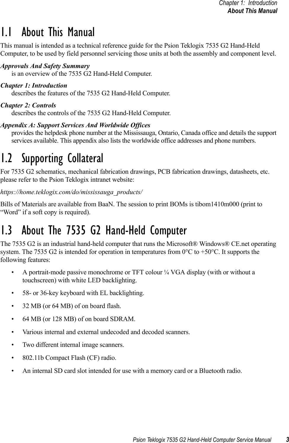
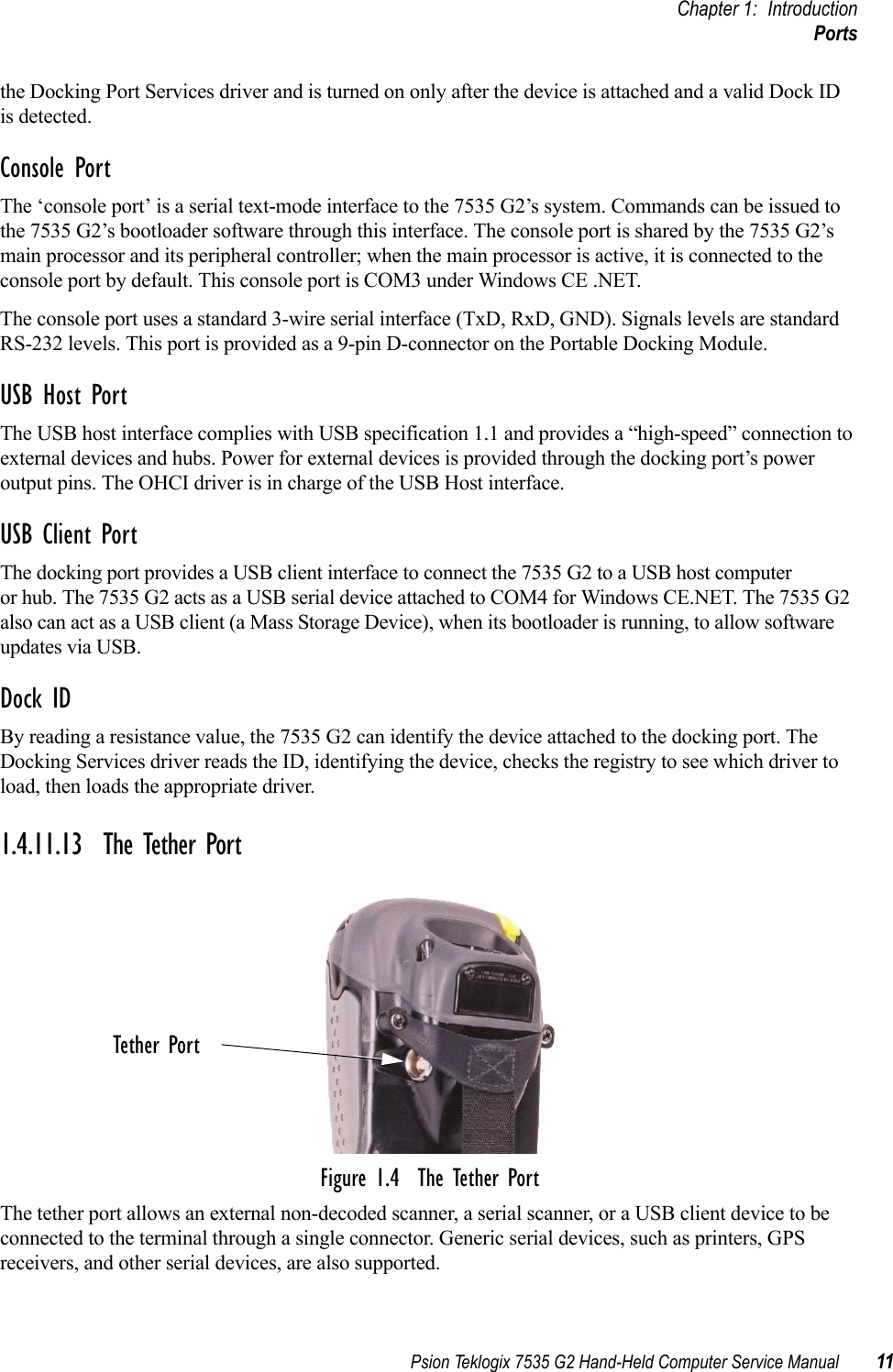
![Chapter 1: IntroductionIdentifying Hardware4Psion Teklogix 7535 G2 Hand-Held Computer Service ManualFigure 1.1 The 7535 G2 Hand-Held Computer1.3.1 Identifying HardwareThe 7535 G2’s hardware configuration is listed in the information provided by the System Properties applet in the Control Panel. To reach this manually:1. Press [BLUE] + <0> to open the start menu. 2. Select Settings > Control Panel. The Control Panel opens.3. Double-click on the System icon. The System Properties window opens.4. Click on the Properties tab. System Properties lists the hardware and software in the 7535 G2.Listed items include:• Date codes for the 7535 G2’s boot software (‘boot code’), peripheral-controller code (‘PCON code’) and OS software (‘WinCE code’).• Processor type and speed.• Amount of RAM and flash memory.• Type and orientation of display.• Presence and type of touch screen.• Presence and type of scanner.• Type of keyboard.](https://usermanual.wiki/Psion/7535G2/User-Guide-635023-Page-14.png)
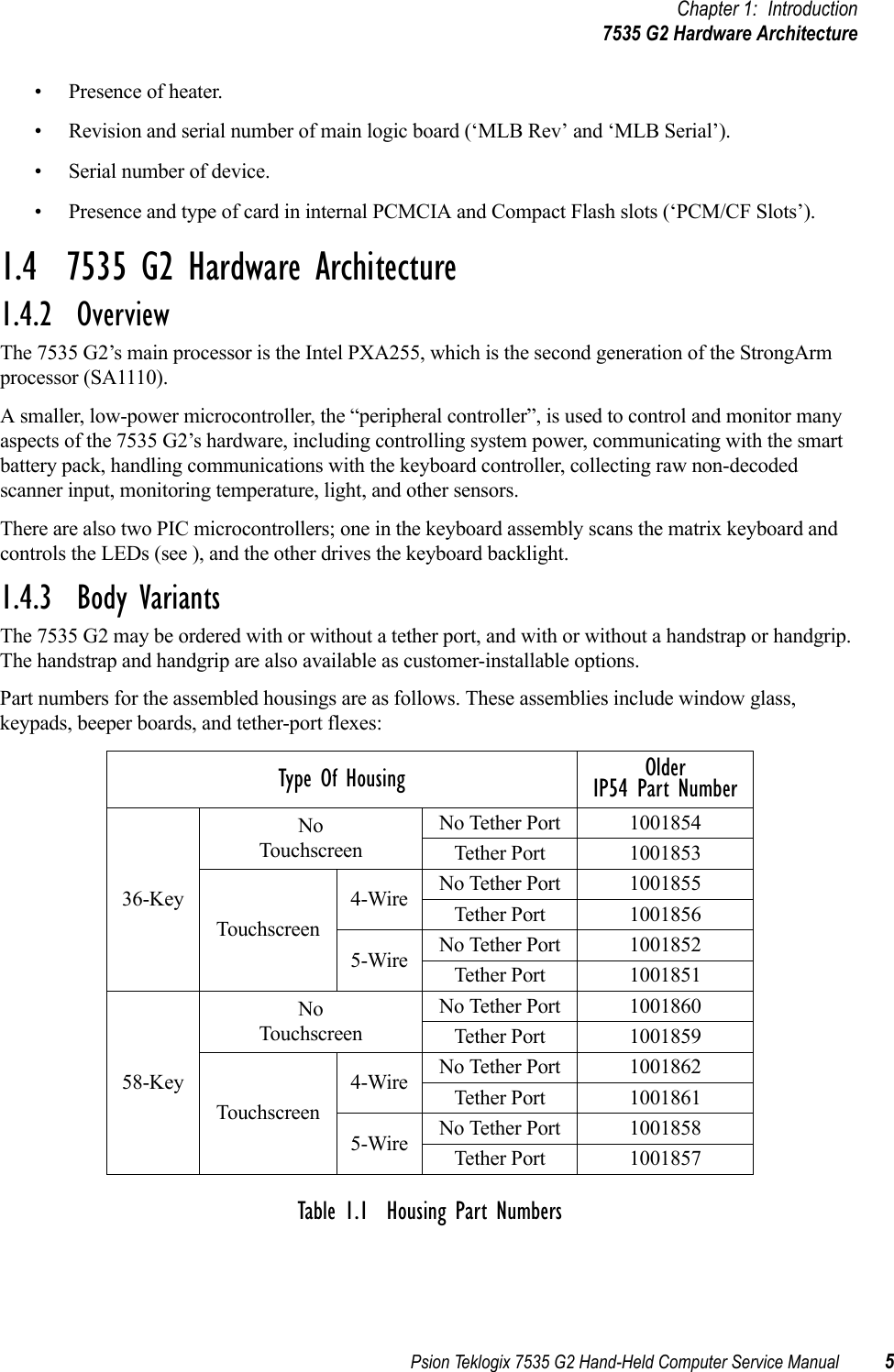
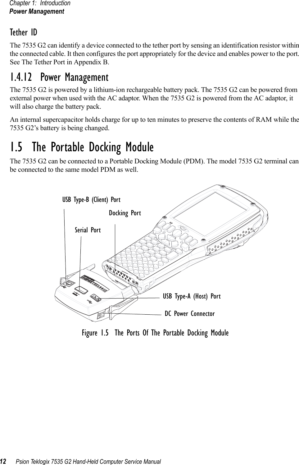
![Psion Teklogix 7535 G2 Hand-Held Computer Service Manual 17Chapter 2: ControlsOverview2.1 OverviewThis chapter describes the controls of the 7535 G2.2.1.1 Identifying HardwareThe 7535 G2’s hardware configuration is listed in the information provided by the System Properties applet in the Control Panel. To reach this manually:1. Press [BLUE] + 0 to open the start menu. 2. Select Settings > Control Panel. The Control Panel opens.3. Double-click on the System icon. The System Properties window opens.4. Click on the Properties tab. Properties lists the hardware and software in the 7535 G2.Listed items include:• Date codes for the 7535 G2’s boot software (‘boot code’), peripheral-controller code (‘PCON code’) and OS software (‘WinCE code’).• Processor type and speed.• Amount of RAM and flash memory.• Type and orientation of display.• Presence and type of touchscreen.• Presence and type of scanner.• Type of keyboard.• Presence of heater.• Serial number of main logic board (‘MLB Serial’).• Serial number of device.• Presence and type of card in internal PCMCIA and Compact Flash slots (‘PCM/CF Slots-’).](https://usermanual.wiki/Psion/7535G2/User-Guide-635023-Page-27.png)
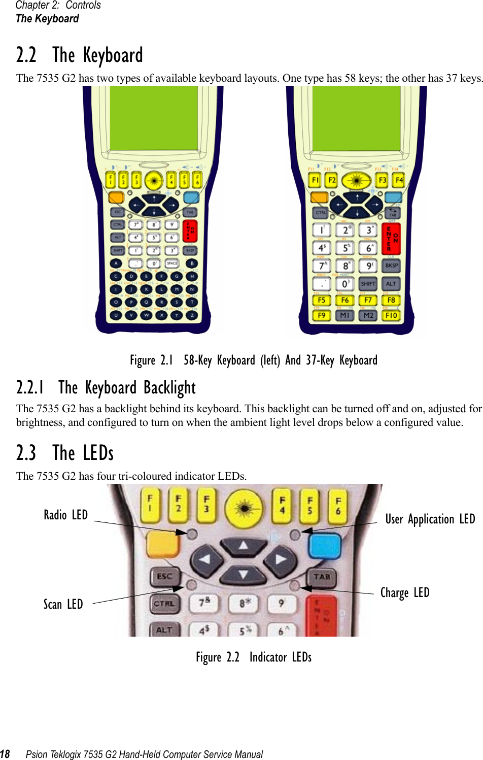
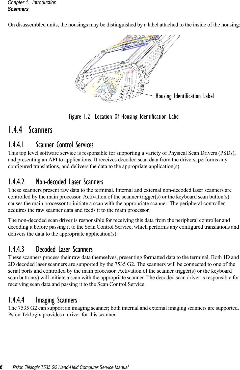
![Chapter 2: ControlsUser Application LED20 Psion Teklogix 7535 G2 Hand-Held Computer Service Manual2.3.4 User Application LEDThis indicator is available for custom applications. Neither the 7535 G2’s operating system nor Psion Teklogix’ terminal-emulator TekTerm use this LED.2.4 The BeeperThe 7535 G2 has an internal beeper whose volume can be manually adjusted via keyboard hot-keys. 2.5 Turning The 7535 G2 On And OffTo switch on: press and hold the [ENTER/ON] key for at least one second.To switch off: press the [BLUE] key, then press the [ENTER/ON] key. The 7535 G2 enters a suspended state. The contents of RAM are preserved.2.6 Resetting The 7535 G2The 7535 G2 hardware can be reset in two different ways. The first way restarts the operating system. The second way does not load the operating system, but presents the bootloader. The bootloader can load the operating system. It has a text-mode console at which commands can be entered.To reset the 7535 G2 and restart the operating system:• Press and hold down the [BLUE] key and the [ENTER/ON] key simultaneously for a minimum of six seconds. The four indicator LEDs light for a second, and the screen displays the Psion Teklogix and Microsoft® Windows® CE.net splash screen before displaying the startup desktop.To reset the 7535 G2 and display the bootloader:• Press and hold down the [SCAN] key, the [BLUE] key and the [ENTER/ON] key simultaneously for a minimum of six seconds. The four indicator LEDs light for a second, and the 7535 G2 displays the boot-loader’s opening screen. A reset results in a complete reboot of the unit. All RAM memory contents are lost. The contents of the flash memory and memory card are preserved.](https://usermanual.wiki/Psion/7535G2/User-Guide-635023-Page-30.png)