Psion 7535G2 HANDHELD COMPUTER User Manual Technical Manual
Psion Inc HANDHELD COMPUTER Technical Manual
Psion >
USERS MNAUAL

Cover
ISO 9001 Certified
Quality Management System
7535 G2
Hand-Held Computer
Service Manual
Month Day, Year Part No. 80000xx.x
© Copyright 2006 by Psion Teklogix Inc., Mississauga, Ontario
This document and the information it contains is the property of Psion Teklogix Inc., is issued in strict confidence,
and is not to be reproduced or copied, in whole or in part, except for the sole purpose of promoting the sale of Tek-
logix manufactured goods and services. Furthermore, this document is not to be used as a basis for design, manufac-
ture, or sub-contract, or in any manner detrimental to the interests of Psion Teklogix Inc.
All trademarks are the property of their respective holders.
Disclaimer
Every effort has been made to make this material complete, accurate, and up-to-date. Psion Teklogix Inc. reserves
the right to make changes without notice and shall not be responsible for any damages, including but not limited to
consequential damages, caused by reliance on the material presented, including but not limited to typographical
errors.

TABLE OF CONTENTS
Psion Teklogix 7535 Hand-Held Computer Technical Manual i
Chapter 1: Introduction
1.1 About This Manual....................................... 3
1.2 Supporting Collateral...................................... 3
1.3 About The 7535 G2 Hand-Held Computer . . . . . . . . . . . . . . . . . . . . . . . . . . . 3
1.3.1 Identifying Hardware.................................. 4
1.4 7535 G2 Hardware Architecture ................................ 5
1.4.1 Overview......................................... 5
1.4.2 Body Variants...................................... 5
1.4.3 Scanners......................................... 6
1.4.3.1 Scanner Control Services ........................... 6
1.4.3.2 Non-decoded Laser Scanners......................... 6
1.4.3.3 Decoded Laser Scanners............................ 6
1.4.3.4 Imaging Scanners............................... 6
1.4.3.5 Scanner Variants................................ 7
1.4.4 The Display....................................... 7
1.4.4.1 Touch Input................................... 7
1.4.4.2 The Display Backlight............................. 7
1.4.4.3 Display Variants................................ 8
1.4.5 The Keyboard...................................... 8
1.4.5.1 The Keyboard Backlight............................ 8
1.4.6 The LEDs........................................ 8
1.4.7 The Beeper........................................ 8
1.4.8 Accessory Cards..................................... 8
1.4.8.1 Card Variants.................................. 9
1.4.9 The Endcap ....................................... 9
1.4.9.1 Endcap Variants................................10
1.4.10Ports...........................................10
1.4.10.1 The Docking Port ...............................10
1.4.10.2 The Tether Port.................................11
1.4.11Power Management...................................12
1.5 The Portable Docking Module . . . . . . . . . . . . . . . . . . . . . . . . . . . . . . . . . 12
Chapter 2: Controls
2.1 Overview ............................................17
2.1.1 Identifying Hardware..................................17
2.2 The Keyboard..........................................18
2.2.1 The Keyboard Backlight.................................18
2.3 The LEDs............................................18
2.3.1 Charge LED.......................................19
2.3.2 Radio Traffic LED....................................19
2.3.3 Scan LED........................................19
2.3.4 User Application LED..................................20
2.4 The Beeper............................................20
2.5 Turning The 7535 G2 On And Off . . . . . . . . . . . . . . . . . . . . . . . . . . . . . . . 20
Contents
ii Psion Teklogix 7535 Hand-Held Computer Technical Manual
2.6 Resetting The 7535 G2.....................................20
Appendices
Appendix A: Support Services And Worldwide Offices
A.1 Technical Support . . . . . . . . . . . . . . . . . . . . . . . . . . . . . . . . . . . . . . . A-1
A.2 Product Repairs........................................A-1
A.3 WorldWide Offices......................................A-2
A.4 Worldwide Web........................................A-2

Psion Teklogix 7535 Hand-Held Computer Technical Manual iii
APPROVALS AND SAFETY SUMMARY
Declaration Of Conformity
Product: 7535 G2 Hand Held Micro-computer with Portable Docking Module
Application of Council R&TTE Directive: 1999/5/EEC
Directive(s): EMC Directive: 89/336/EEC
Low Voltage Directive: 73/23/EEC
Conformity Declared Article 3.1a (Health): EN 60950: 2000
to Standards: Article 3.1b (EMC): EN 301 489-17: v1.1.1; 09-2000
Article 3.2 (RF Spectrum): EN 300 328-2: v 1.1.1; 07 2000
EN 55022: 1998 + Am 1, Class B;
EN 61000-3-2; EN 61000-3-3
EN 55024:1998;
EN 61000-4-2; ±4kV CD; ±8kV AD
EN 61000-4-3; 3V/m, 80-1000 MHz
EN 61000-4-4; ±1kV Power lines
EN 61000-4-5; ±1kV Differential mode
EN 61000-4-6; 3VRMS, 150kHz-80MHz
EN 61000-4-11; AC Mains Ports
Manufacturer: PSION TEKLOGIX INC.
2100 Meadowvale Boulevard
Mississauga, Ontario, Canada
L5N 7J9
Year of Manufacture: 2003
Manufacturer’s Address PSION TEKLOGIX S.A.
in the European La Duranne; 135 Rue Rene Descartes; BP 421000
Community: 13591 Aix-En-Provence
Cedex 3; France
Type of Equipment: Information Technology Equipment
Equipment Class: Commercial and Light Industrial
I the undersigned hereby declare that the equipment specified above conforms to the above
directives and standards.
Manufacturer: Rob Williams
Vice President of Engineering
Psion Teklogix Inc. Ontario
Legal Representative Domique Binckly
Vice President International Sales
Psion Teklogix S.A. France

Safety
iv Psion Teklogix 7535 Hand-Held Computer Technical Manual
FCC DECLARATION OF CONFORMITY (DoC)
Applicant’s Name & Address: PSION TEKLOGIX
2100 Meadowvale Blvd.
Mississauga, Ontario
Canada L5N 7J9
Contact Person: Iain Roy
Telephone No.: (905) 813-9900
US Representative’s Name & Address: 1810 Airport Exchange Blvd., Suite 500
Erlanger, KY, 41018, USA
Contact Person: Joe Musgrave
Telephone No.: (859) 372-4106
Equipment Type/Environment: Computing Devices
Trade Name / Model No.: 7535 G2 Hand Held Micro-computer with
Portable Docking Module
Year of Manufacture: 2003
Standard(s) to which Conformity is Declared:
The 7535 G2 Hand Held Micro-computer with Portable Docking Module, supplied by Psion Teklogix,
has been tested and found to comply with FCC PART 15, SUBPART B - UNINTENTIONAL
RADIATORS, CLASS B COMPUTING DEVICES FOR HOME & OFFICE USE.
I, the undersigned, hereby declare that the equipment as tested is representative within manufacturing
tolerance to units.
Applicant Legal Representative in U.S.
Signature Signature
Rob Williams Joe Musgrave
Full Name Full Name
Vice President of Engineering V.P. Global Solutions, Americas
Position Position
Mississauga, Ontario, Canada Erlanger, KY 41018, USA
Place Place
July 4, 2003 July 4, 2003
Date Date

Psion Teklogix 7535 Hand-Held Computer Technical Manual v
Safety
CE MARKING
When used in a residential, commercial or light industrial environment the product and its
approved UK and European peripherals fulfil all requirements for CE marking.
R&TTE DIRECTIVE 1999/5/EC
This equipment complies with the essential requirements of EU Directive 1999/5/EC (Decla-
ration available: www.psionteklogix.com).
Cet équipement est conforme aux principales caractéristiques définies dans la Directive
européenne RTTE 1999/5/CE. (Déclaration disponible sur le site: www.psionteklogix.com).
Die Geräte erfüllen die grundlegenden Anforderungen der RTTE-Richtlinie (1999/5/EG).
(Den Wortlaut der Richtlinie finden Sie unter: www.psionteklogix.com).
Questa apparecchiatura è conforme ai requisiti essenziali della Direttiva Europea R&TTE
1999/5/CE. (Dichiarazione disponibile sul sito: www.psionteklogix.com).
Este equipo cumple los requisitos principales de la Directiva 1995/5/CE de la UE, “Equipos
de Terminales de Radio y Telecomu-nicaciones”. (Declaración disponible en: www.psiontek-
logix.com).
Este equipamento cumpre os requisitos essenciais da Directiva 1999/5/CE do Parlamento
Europeu e do Conselho (Directiva RTT). (Declaração disponível no endereço: www.psiontek-
logix.com).
Ο εξοπλισμός αυτός πληροί τις βασικές απαιτήσεις της κοινοτικής οδηγίας EU R&TTE
1999/5/EΚ. (Η δήλωση συμμόρφωσης διατίθεται στη διεύθυνση: www.psionteklogix.com)
Deze apparatuur voldoet aan de noodzakelijke vereisten van EU-richtlijn betreffende radioap-
IMPORTANT: WASTE ELECTRICAL AND ELECTRONIC EQUIPMENT (WEEE) DIRECTIVE 2002/96/EC
If your product or accessory displays the above logo, then the following statement applies.
This Product, and its accessories, comply with the requirements of the Waste Electrical and Electronic
Equipment (WEEE) Directive 2002/96/EC. If your end-of-life Psion Teklogix product or accessory
was first placed on the European Union market on or after August 13
th , 2005, contact your local
country representative for details on how to arrange recycling.
For a list of international subsidiaries, please visit: www.psionteklogix.com/
Safety
vi Psion Teklogix 7535 Hand-Held Computer Technical Manual
paratuur en telecommunicatie-eindappa-ratuur 199/5/EG. (verklaring beschikbaar:
www.psionteklogix.com).
Dette udstyr opfylder de Væsentlige krav i EU's direktiv 1999/5/EC om Radio- og teletermi-
naludstyr. (Erklæring findes på: www.psionteklogix.com).
Dette utstyret er i overensstemmelse med hovedkravene i R&TTE-direktivet (1999/5/EC) fra
EU. (Erklæring finnes på: www.psionteklogix.com).
Utrustningen uppfyller kraven för EU-direktivet 1999/5/EC om ansluten teleutrustning och
ömsesidigt erkännande av utrustningens överensstämmelse (R&TTE). (Förklaringen finns att
läsa på: www.psionteklogix.com).
Tämä laite vastaa EU:n radio- ja telepäätelaitedirektiivin (EU R&TTE Directive 1999/5/EC)
vaatimuksia. (Julkilausuma nähtävillä osoitteessa: www.psionteklogix.com).
Use of the 802.11b 7535 G2 in France:
Owing to French Government restrictions, the 802.11b 7535 G2 Hand-Held Computers are limited to
indoor use. They may be used outdoors, on private property, only with prior authorization from the
French Ministry of Defense.
For GSM/GPRS Users in North America:
Although the GSM/GPRS Expansion Module is a three band device; only the 1900 (PCS) band is used in
North America.
This equipment complies with Class B Part 15 of the FCC rules.
Operation is subject to the following two conditions:
1. This device may not cause harmful interference, and
2. This device must accept any interference received, including interference that may cause
undesired operation.

Psion Teklogix 7535 Hand-Held Computer Technical Manual vii
Safety
Changes or modifications not expressly approved by Psion Teklogix, the party responsible for
compliance, may void the user's authority to operate the equipment.
1. FCC Information to Users
For Class B Unintentional Radiators:
This equipment has been tested and found to comply with the limits for a Class B digital device, pursu-
ant to Part 15 of the FCC Rules. These limits are designed to provide reasonable protection against
harmful interference in a residential installation. This equipment generates, uses, and can radiate radio
frequency energy and, if not installed and used in accordance with the instruction manual, may cause
harmful interference to radio communications. However, there is no guarantee that interference will
not occur in a particular installation. If this equipment does cause harmful interference to radio or tele-
vision reception, which can be determined by turning the equipment off and on, the user is encouraged
to try to correct the interference by one of more of the following measures:
• Reorient or relocate the receiving antenna
• Increase the separation between the equipment and receiver
• Connect the equipment into an outlet on a circuit different from that to which the receiver is
connected.
• Consult the dealer or an experienced radio/TV technician for help.
2. Warning to Users
Warning: Changes or modifications not expressly approved by Psion Teklogix Inc. could void the
user's authority to operate the equipment.
LASER WARNINGS
For your own safety, it is critical that you comply with the following warnings:
CAUTION
Do not look into the laser beam or point the beam at people or animals.
CAUTION
Using controls or adjustments, or performing procedures other than those specified herein may
result in hazardous radiation exposure.
CAUTION
The use of optical instruments with this product will increase eye hazard.
This product contains a laser scanner that emits less than 1.2 mW maximum radiant power at a
wavelength of 650nm or 680nm. This product complies with 21 CFR 1040.10, 1040.11 and DIN EN
60825-1: 2001, and is classified as a Class 2 laser product.
The SE1200 ALR has an maximum radiated power less than 1.4 mW; according to EN 60825-1: 2001 it
is classified as a Class 3B laser product.

Safety
viii Psion Teklogix 7535 Hand-Held Computer Technical Manual
DO NOT OPERATE IN AN EXPLOSIVE ATMOSPHERE
Operating Psion Teklogix equipment where explosive gas is present may result in an explosion.
DO NOT REMOVE COVERS OR OPEN ENCLOSURES
To avoid injury, the equipment covers and enclosures should only be removed by qualified service
personnel. Do not operate the equipment without the covers and enclosures properly installed.
CAUTION!
Danger of explosion if a 7535 G2 battery is incorrectly handled, charged, disposed of or replaced.
Replace only with the same or equivalent type recommended by the manufacturer. Dispose of used
batteries according to the instructions described in “Lithium-Ion Battery Safety Precautions” on page 252
of the 7535 G2 User Manual. Carefully review all battery safety issues.

Psion Teklogix 7535 G2 Hand-Held Computer Service Manual 1
INTRODUCTION 1
1.1 About This Manual . . . . . . . . . . . . . . . . . . . . . . . . . . . . . . . . . . . . . . . . . . 3
1.2 Supporting Collateral......................................... 3
1.3 About The 7535 G2 Hand-Held Computer. . . . . . . . . . . . . . . . . . . . . . . . . . . . . . 3
1.3.1 Identifying Hardware................................... 4
1.4 7535 G2 Hardware Architecture................................... 5
1.3.1 Identifying Hardware................................... 4
1.4.2 Overview.......................................... 5
1.4.3 Body Variants....................................... 5
1.4.4 Scanners.......................................... 6
1.4.5 The Display........................................ 7
1.4.6 The Keyboard....................................... 8
1.4.7 The LEDs......................................... 8
1.4.8 The Beeper......................................... 8
1.4.9 Accessory Cards...................................... 8
1.4.10 The Endcap........................................ 9
1.4.11 Ports............................................10
1.4.12 Power Management ...................................12
1.5 The Portable Docking Module....................................12
Psion Teklogix 7535 G2 Hand-Held Computer Service Manual 3
Chapter 1: Introduction
About This Manual
1.1 About This Manual
This manual is intended as a technical reference guide for the Psion Teklogix 7535 G2 Hand-Held
Computer, to be used by field personnel servicing those units at both the assembly and component level.
Approvals And Safety Summary
is an overview of the 7535 G2 Hand-Held Computer.
Chapter 1: Introduction
describes the features of the 7535 G2 Hand-Held Computer.
Chapter 2: Controls
describes the controls of the 7535 G2 Hand-Held Computer.
Appendix A: Support Services And Worldwide Offices
provides the helpdesk phone number at the Mississauga, Ontario, Canada office and details the support
services available. This appendix also lists the worldwide office addresses and phone numbers.
1.2 Supporting Collateral
For 7535 G2 schematics, mechanical fabrication drawings, PCB fabrication drawings, datasheets, etc.
please refer to the Psion Teklogix intranet website:
https://home.teklogix.com/do/mississauga_products/
Bills of Materials are available from BaaN. The session to print BOMs is tibom1410m000 (print to
“Word” if a soft copy is required).
1.3 About The 7535 G2 Hand-Held Computer
The 7535 G2 is an industrial hand-held computer that runs the Microsoft® Windows® CE.net operating
system. The 7535 G2 is intended for operation in temperatures from 0°C to +50°C. It supports the
following features:
• A portrait-mode passive monochrome or TFT colour ¼ VGA display (with or without a
touchscreen) with white LED backlighting.
• 58- or 36-key keyboard with EL backlighting.
• 32 MB (or 64 MB) of on board flash.
• 64 MB (or 128 MB) of on board SDRAM.
• Various internal and external undecoded and decoded scanners.
• Two different internal image scanners.
• 802.11b Compact Flash (CF) radio.
• An internal SD card slot intended for use with a memory card or a Bluetooth radio.
Chapter 1: Introduction
Identifying Hardware
4Psion Teklogix 7535 G2 Hand-Held Computer Service Manual
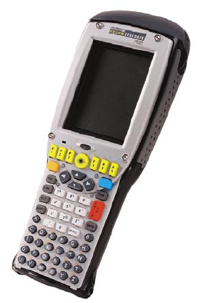
Figure 1.1 The 7535 G2 Hand-Held Computer
1.3.1 Identifying Hardware
The 7535 G2’s hardware configuration is listed in the information provided by the System Properties
applet in the Control Panel.
To reach this manually:
1. Press [BLUE] + <0> to open the start menu.
2. Select Settings > Control Panel. The Control Panel opens.
3. Double-click on the System icon. The System Properties window opens.
4. Click on the Properties tab. System Properties lists the hardware and software in the 7535
G2.
Listed items include:
• Date codes for the 7535 G2’s boot software (‘boot code’), peripheral-controller code (‘PCON
code’) and OS software (‘WinCE code’).
• Processor type and speed.
• Amount of RAM and flash memory.
• Type and orientation of display.
• Presence and type of touch screen.
• Presence and type of scanner.
• Type of keyboard.

Psion Teklogix 7535 G2 Hand-Held Computer Service Manual 5
Chapter 1: Introduction
7535 G2 Hardware Architecture
• Presence of heater.
• Revision and serial number of main logic board (‘MLB Rev’ and ‘MLB Serial’).
• Serial number of device.
• Presence and type of card in internal PCMCIA and Compact Flash slots (‘PCM/CF Slots’).
1.4 7535 G2 Hardware Architecture
1.4.2 Overview
The 7535 G2’s main processor is the Intel PXA255, which is the second generation of the StrongArm
processor (SA1110).
A smaller, low-power microcontroller, the “peripheral controller”, is used to control and monitor many
aspects of the 7535 G2’s hardware, including controlling system power, communicating with the smart
battery pack, handling communications with the keyboard controller, collecting raw non-decoded
scanner input, monitoring temperature, light, and other sensors.
There are also two PIC microcontrollers; one in the keyboard assembly scans the matrix keyboard and
controls the LEDs (see ), and the other drives the keyboard backlight.
1.4.3 Body Variants
The 7535 G2 may be ordered with or without a tether port, and with or without a handstrap or handgrip.
The handstrap and handgrip are also available as customer-installable options.
Part numbers for the assembled housings are as follows. These assemblies include window glass,
keypads, beeper boards, and tether-port flexes:
Table 1.1 Housing Part Numbers
Type Of Housing Older
IP54 Part Number
36-Key
No
Touchscreen
No Tether Port 1001854
Tether Port 1001853
Touchscreen
4-Wire No Tether Port 1001855
Tether Port 1001856
5-Wire No Tether Port 1001852
Tether Port 1001851
58-Key
No
Touchscreen
No Tether Port 1001860
Tether Port 1001859
Touchscreen
4-Wire No Tether Port 1001862
Tether Port 1001861
5-Wire No Tether Port 1001858
Tether Port 1001857
Chapter 1: Introduction
Scanners
6Psion Teklogix 7535 G2 Hand-Held Computer Service Manual
On disassembled units, the housings may be distinguished by a label attached to the inside of the housing:
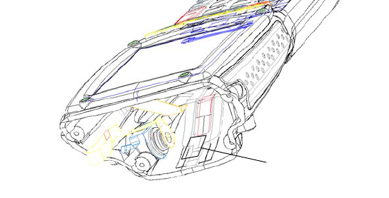
Figure 1.2 Location Of Housing Identification Label
1.4.4 Scanners
1.4.4.1 Scanner Control Services
This top level software service is responsible for supporting a variety of Physical Scan Drivers (PSDs),
and presenting an API to applications. It receives decoded scan data from the drivers, performs any
configured translations, and delivers the data to the appropriate application(s).
1.4.4.2 Non-decoded Laser Scanners
These scanners present raw data to the terminal. Internal and external non-decoded laser scanners are
controlled by the main processor. Activation of the scanner trigger(s) or the keyboard scan button(s)
causes the main processor to initiate a scan with the appropriate scanner. The peripheral controller
acquires the raw scanner data and feeds it to the main processor.
The non-decoded scan driver is responsible for receiving this data from the peripheral controller and
decoding it before passing it to the Scan Control Service, which performs any configured translations and
delivers the data to the appropriate application(s).
1.4.4.3 Decoded Laser Scanners
These scanners process their raw data themselves, presenting formatted data to the terminal. Both 1D and
2D decoded laser scanners are supported by the 7535 G2. The scanners will be connected to one of the
serial ports and controlled by the main processor. Activation of the scanner trigger(s) or the keyboard
scan button(s) will initiate a scan with the appropriate scanner. The decoded scan driver is responsible for
receiving scan data and passing it to the Scan Control Service.
1.4.4.4 Imaging Scanners
The 7535 G2 can support an imaging scanner; both internal and external imaging scanners are supported.
Psion Teklogix provides a driver for this scanner.
Housing Identification Label
Psion Teklogix 7535 G2 Hand-Held Computer Service Manual 7
Chapter 1: Introduction
The Display
1.4.4.5 Scanner Variants
The following internal scanner devices (scanners and RFID readers) can be included with the 7535 G2:
• Wide-angle undecoded 1-D laser scanner (Psion Teklogix assembly part number 10xxxxx).
• Standard undecoded 1-D laser scanner (part number 1001833).
• Long-range undecoded 1-D laser scanner (part number 1001834).
• Advanced long-range undecoded 1-D laser scanner (part number 1001835).
• Fuzzy-logic decoded 1-D laser scanner (part number 1001836).
• PDF417 decoded 2-D laser scanner (part number 1001837).
• VGA decoded imaging scanner (part number 1001838).
• XVGA decoded imaging scanner (part number 1001839).
• Long-range XVGA decoded imaging scanner (part number 1001840).
• XVGA high-density decoded imaging scanner (part number 1001841).
• XVGA infinite-focus decoded imaging scanner (part number 1001847).
• RFID reader (part number 1001843).
• Scanner/RFID reader combination (part number 1001842).
An option for no scanner is also available (part number 1020022).
The internal scanner device connects through the ScanBay interface.
Only one internal scanner is installed in the 7535 G2, but a second hand-held scanner can be connected
via the tether port. Internal scanners can be triggered from the trigger switch on the 7535 G2’s handgrip
(if present) or from the Scan button on the 7535 G2’s keyboard. External scanners can only be triggered
from their own trigger switch.
1.4.5 The Display
The 7535 G2 is available with a 240x320-pixel display, either monochrome (64 shades of grey) or colour
(256k colours). The contrast of the display can be adjusted from the keyboard via hot-keys, and is
automatically temperature-compensated.
1.4.5.6 Touch Input
Touch input is an option for the 7535 G2’s display. The touch driver controls the hardware directly to
receive touch-down, touch-up, and movement events. Touch events are passed to the application via the
operating system.
1.4.5.7 The Display Backlight
The 7535 G2 has a backlight behind its display. This backlight can be adjusted for intensity, and can be
configured to turn on when the ambient light level drops below a configured value.

Chapter 1: Introduction
The Keyboard
8Psion Teklogix 7535 G2 Hand-Held Computer Service Manual
1.4.5.8 Display Variants
The 7535 G2 is available with the following displays:
• Colour with no touch screen.
• Colour with 4-wire touch screen.
• Colour with 5-wire touch screen.
The touch screen is provided as part of the display window glass. Devices with no touch screen have
plain glass.The 5-wire touch screen is more accurate than the 4-wire touch screen, but is more fragile.
The display and touch screen are connected to the motherboard of the 7535 G2 through a Display
Transition Board (DTB). The displays with the 4-wire touch screen use a DTB with part number
1916135-004; other displays (those with no touch screen and with the 5-wire touch screen) use DTB
1916135-001.
Table 1.2 Display Options For The 7535 G2
1.4.6 The Keyboard
The 7535 G2 has two types of available keyboard layouts. One type has 58 keys; the other has 37 keys.
Windows CE .NET returns ‘virtual key codes’ for keypresses. Psion Teklogix’ keyboard drivers take into
account when Psion Teklogix’ own special modifier keys (such as the Blue or Orange key) are pressed;
the keyboard driver provides the virtual key code of the modified key.
1.4.6.9 The Keyboard Backlight
The 7535 G2 has a backlight behind its keyboard. This backlight can be adjusted for intensity, and can be
configured to turn on when the ambient light level drops below a configured value.
1.4.7 The LEDs
The 7535 G2 has four tri-coloured indicator LEDs.
1.4.8 The Beeper
The 7535 G2 has an internal beeper whose volume can be manually adjusted via keyboard hot-keys.
1.4.9 Accessory Cards
The 7535 G2 can accept accessory cards, which fit into internal slots in the unit. These cards can contain
additional memory, a radio, or other accessories. Typically, 7535 G2 hand-held computers are configured
at the factory and arrive ready for use. These slots are accessible when the terminal’s endcap is
removed.The 7535 G2’s accessory-card slots are not intended for user modification.
Display Display Part
Number Display
Transition Board Touchscreen Window Part Number
Colour 1030033-001 1916145-001 none 1020052-001 (glass)
5-wire 1030079-999 (5-wire touchscreen)
1916145-004 4-wire 1030170-999 (4-wire touchscreen)

Psion Teklogix 7535 G2 Hand-Held Computer Service Manual 9
Chapter 1: Introduction
The Endcap
1.4.9.10 Card Variants
The 7535 G2 has two internal card slots, one for a Compact Flash card, and one for an MMC/SD card.
The Compact Flash slot is normally occupied by a radio. It can accept the following cards:
• A memory card (64, 128, 256, or 512 megabytes).
• An 802.11g radio card with internal or external antenna.
Compact-flash memory cards available for the 7535 G2 have included the following:
Table 1.3 Compact-Flash Memory Cards For The 7535 G2
Compact-flash radio cards available for the 7535 G2 have included the following:
Table 1.4 Compact-Flash Radio Cards For The 7535 G2
The MMC/SD slot also supports SDIO cards. It can accept the following cards:
• A memory card (64, 128, 256, 512, 0r 1024 megabytes).
• A radio card (Bluetooth or 802.11b).
MMC/SD cards available for the 7535 G2 have included the following:
Table 1.5 MMC/SD Cards For The 7535 G2
1.4.10 The Endcap
The 7535 G2’s endcap covers the end of the unit, incorporating the window for the internal scanner, if
necessary. It can be removed to give access to the card slots and the interior of the unit.
Part Number Description
9003419 64-megabyte CompactFlash memory card
9003420 128-megabyte CompactFlash memory card
9003421 256-megabyte CompactFlash memory card
9003422 512-megabyte CompactFlash memory card
Part Number Description
1001933-001 802.11g radio card for USA
1001933-002 802.11g radio card for Europe
1001935 quad-band GSM radio card
Part Number Description
9001955 64-megabyte SD memory card
9001956 128-megabyte SD memory card
9001957 256-megabyte SD memory card
9001958 512-megabyte SD memory card
9001959 1024-megabyte SD memory card
1001936-001 802.11b radio card for USA
1001936-002 802.11b radio card for Europe
9001894 Bluetooth radio card
Chapter 1: Introduction
Ports
10 Psion Teklogix 7535 G2 Hand-Held Computer Service Manual
1.4.10.11 Endcap Variants
There are five variants of the 7535 G2’s endcap:
Table 1.6 Endcap Variants
The external RFID reader, model RD7950, fits over the 7535 G2’s endcap, leaving room for the scanner.
1.4.11 Ports
The 7535 G2 has the following external ports:
• Docking port.
Connects to chargers and docking modules; provides USB and serial connections.
• Tether port.
Connects scanners and other cabled peripherals.
See Appendix B for detailed descriptions and pinouts.
1.4.11.12 The Docking Port
The docking port allows the terminal to be placed in a cradle that allows battery charging and connection
to peripherals. Available peripherals include chargers and a Portable Docking Module (PDM) that
provides connections for USB host port, USB client port, and a serial port. See “The Portable Docking
Module” on page 12 for details about the PDM.
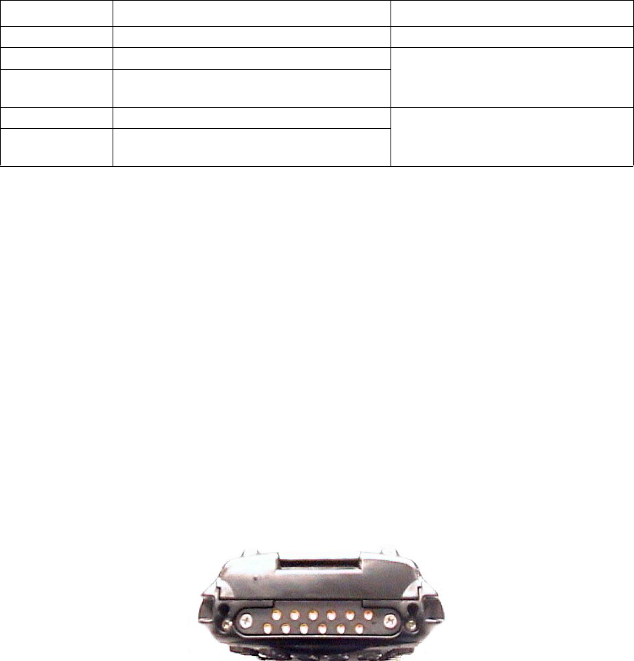
Figure 1.3 The Docking Port
The docking port supplies DC power, a serial ‘console’ port, a USB host port, and a USB client port.
Power
Power for charging the batteries and powering the terminal (9-24 V DC; 3.4 A max) is supplied to the
terminal through the docking port. The terminal can supply 5V power (1.5 A max, 1A continuous) to
an external device through the ‘Power Output’ pin. This power is switched; the switch is controlled by
Part Number Description Notes
1001737 Endcap without scanner
1001739 Endcap with scanner window This endcap is used with all the scanners
except the imaging scanners.
1001336 Endcap with scanner window, for units with
GSM radio.
1001735 Endcap with imaging-scanner window This endcap is used with the two imaging
scanners, 1030048 and 1030049
1001391 Endcap with imaging-scanner window, for
units with GSM radio.
Psion Teklogix 7535 G2 Hand-Held Computer Service Manual 11
Chapter 1: Introduction
Ports
the Docking Port Services driver and is turned on only after the device is attached and a valid Dock ID
is detected.
Console Port
The ‘console port’ is a serial text-mode interface to the 7535 G2’s system. Commands can be issued to
the 7535 G2’s bootloader software through this interface. The console port is shared by the 7535 G2’s
main processor and its peripheral controller; when the main processor is active, it is connected to the
console port by default. This console port is COM3 under Windows CE .NET.
The console port uses a standard 3-wire serial interface (TxD, RxD, GND). Signals levels are standard
RS-232 levels. This port is provided as a 9-pin D-connector on the Portable Docking Module.
USB Host Port
The USB host interface complies with USB specification 1.1 and provides a “high-speed” connection to
external devices and hubs. Power for external devices is provided through the docking port’s power
output pins. The OHCI driver is in charge of the USB Host interface.
USB Client Port
The docking port provides a USB client interface to connect the 7535 G2 to a USB host computer
or hub. The 7535 G2 acts as a USB serial device attached to COM4 for Windows CE.NET. The 7535 G2
also can act as a USB client (a Mass Storage Device), when its bootloader is running, to allow software
updates via USB.
Dock ID
By reading a resistance value, the 7535 G2 can identify the device attached to the docking port. The
Docking Services driver reads the ID, identifying the device, checks the registry to see which driver to
load, then loads the appropriate driver.
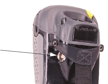
1.4.11.13 The Tether Port
Figure 1.4 The Tether Port
The tether port allows an external non-decoded scanner, a serial scanner, or a USB client device to be
connected to the terminal through a single connector. Generic serial devices, such as printers, GPS
receivers, and other serial devices, are also supported.
Tether Port
Chapter 1: Introduction
Power Management
12 Psion Teklogix 7535 G2 Hand-Held Computer Service Manual
Tether ID
The 7535 G2 can identify a device connected to the tether port by sensing an identification resistor within
the connected cable. It then configures the port appropriately for the device and enables power to the port.
See The Tether Port in Appendix B.
1.4.12 Power Management
The 7535 G2 is powered by a lithium-ion rechargeable battery pack. The 7535 G2 can be powered from
external power when used with the AC adaptor. When the 7535 G2 is powered from the AC adaptor, it
will also charge the battery pack.
An internal supercapacitor holds charge for up to ten minutes to preserve the contents of RAM while the
7535 G2’s battery is being changed.
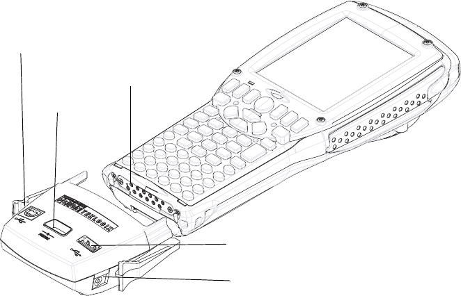
1.5 The Portable Docking Module
The 7535 G2 can be connected to a Portable Docking Module (PDM). The model 7535 G2 terminal can
be connected to the same model PDM as well.
Figure 1.5 The Ports Of The Portable Docking Module
USB Type-B (Client) Port
Serial Port
Docking Port
USB Type-A (Host) Port
DC Power Connector
Psion Teklogix 7535 G2 Hand-Held Computer Service Manual 13
Chapter 1: Introduction
The Portable Docking Module
The Portable Docking Module provides serial and USB ports. The PDM has the following ports:
•Serial port.
This 9-pin D-connector accepts a null-modem serial cable which connects to an external
development machine.
•USB type B port.
This port accepts a cable from a USB host (typically the development machine).
•USB type A port.
This port connects the 7535 G2 to other devices; the 7535 G2 serves as a USB host.
• Docking port.
This port connects to the 7535 G2.
• DC power connector.
Accepts 15 V DC from the power adaptor.
The Portable Docking Module is available as part of a kit from Psion Teklogix. This kit, Psion Teklogix
part number 1030085, includes the following items:
• The Portable Docking Module (part number 1030083-001).
• A USB A-B cable (part number 9003322).
• A null modem cable (part number 9003659).
• An AC-to-DC power adaptor (part number 9007558).
• A power cord. (North American power cord: part number 9008693).

Psion Teklogix 7535 G2 Hand-Held Computer Service Manual 15
CONTROLS 2
2.1 Overview...............................................17
2.1.1 Identifying Hardware...................................17
2.2 The Keyboard.............................................18
2.2.1 The Keyboard Backlight..................................18
2.3 The LEDs...............................................18
2.3.1 Charge LED........................................19
2.3.2 Radio Traffic LED.....................................19
2.3.3 Scan LED.........................................19
2.3.4 User Application LED...................................20
2.4 The Beeper..............................................20
2.5 Turning The 7535 G2 On And Off..................................20
2.6 Resetting The 7535 G2 . . . . . . . . . . . . . . . . . . . . . . . . . . . . . . . . . . . . . . . . 20
Psion Teklogix 7535 G2 Hand-Held Computer Service Manual 17
Chapter 2: Controls
Overview
2.1 Overview
This chapter describes the controls of the 7535 G2.
2.1.1 Identifying Hardware
The 7535 G2’s hardware configuration is listed in the information provided by the System Properties
applet in the Control Panel.
To reach this manually:
1. Press [BLUE] + 0 to open the start menu.
2. Select Settings > Control Panel. The Control Panel opens.
3. Double-click on the System icon. The System Properties window opens.
4. Click on the Properties tab. Properties lists the hardware and software in the 7535 G2.
Listed items include:
• Date codes for the 7535 G2’s boot software (‘boot code’), peripheral-controller code (‘PCON
code’) and OS software (‘WinCE code’).
• Processor type and speed.
• Amount of RAM and flash memory.
• Type and orientation of display.
• Presence and type of touchscreen.
• Presence and type of scanner.
• Type of keyboard.
• Presence of heater.
• Serial number of main logic board (‘MLB Serial’).
• Serial number of device.
• Presence and type of card in internal PCMCIA and Compact Flash slots (‘PCM/CF Slots-’).
Chapter 2: Controls
The Keyboard
18 Psion Teklogix 7535 G2 Hand-Held Computer Service Manual
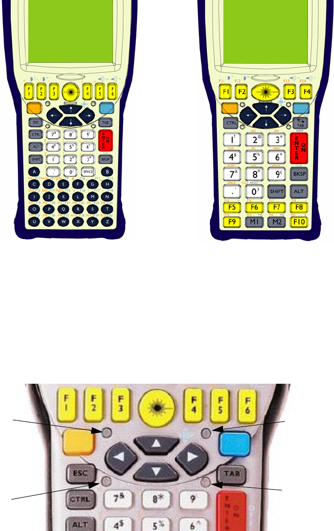
2.2 The Keyboard
The 7535 G2 has two types of available keyboard layouts. One type has 58 keys; the other has 37 keys.
Figure 2.1 58-Key Keyboard (left) And 37-Key Keyboard
2.2.1 The Keyboard Backlight
The 7535 G2 has a backlight behind its keyboard. This backlight can be turned off and on, adjusted for
brightness, and configured to turn on when the ambient light level drops below a configured value.
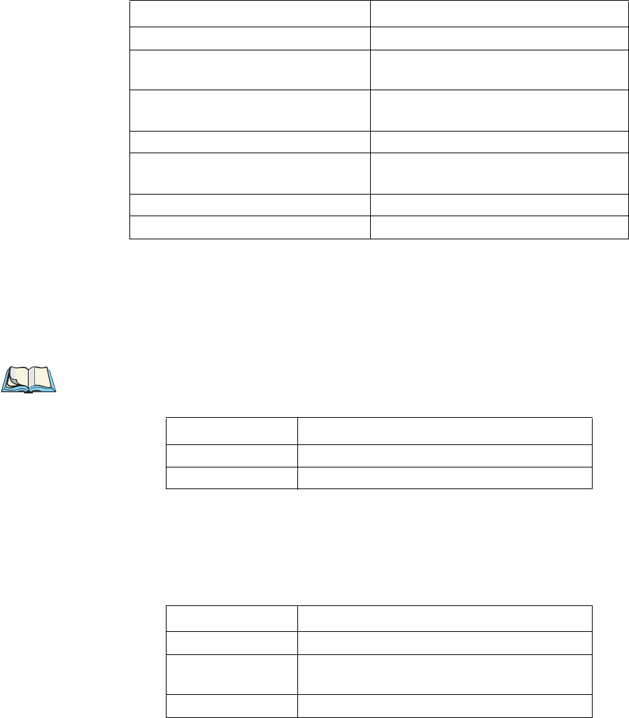
2.3 The LEDs
The 7535 G2 has four tri-coloured indicator LEDs.
Figure 2.2 Indicator LEDs
User Application LED
Charge LED
Scan LED
Radio LED
Psion Teklogix 7535 G2 Hand-Held Computer Service Manual 19
Chapter 2: Controls
Charge LED
2.3.1 Charge LED
The lower-right LED is reserved for internal charger/power status. This indicator is active even when the
7535 G2 is inserted in a docking station (and in suspend mode) so that the charge status of the battery can
be detected easily.
2.3.2 Radio Traffic LED
The upper-left LED on the 7535 G2 flashes yellow or green when the radio transmits and receives data.
Note: While the standard 802.11b radio available for the 7535 G2 supports the transmit/receive
LED, not all radios support this function.
2.3.3 Scan LED
Successful scans are indicated in two ways – by the scan LED and with an audio tone.
Function Charge LED Behaviour
External power not available. LED off.
Fully charged to within 95% of
charge capacity. LED displays solid green colour.
Quick charge successfully completed
to within 75% of charge capacity. LED flashes slow green.
Charge in progress. LED displays solid yellow colour.
Cell temperature out of range for
charge. LED flashes yellow.
Unable to charge battery. LED displays solid red colour.
Charge circuit failure. LED flashes fast red.
Table 2.1 Charge LEDs
Function Radio Traffic LED Behaviour
Radio Transmit LED flashes yellow.
Radio Receive LED flashes green.
Table 2.2 Transmit and Receive LEDs
Function Scan LED Behaviour
Scan in progress LED displays solid red during scan.
Successful scan LED displays solid green after decode.
Off when scan ended.
Unsuccessful scan LED flashes red.
Table 2.3 Scan LED
Chapter 2: Controls
User Application LED
20 Psion Teklogix 7535 G2 Hand-Held Computer Service Manual
2.3.4 User Application LED
This indicator is available for custom applications. Neither the 7535 G2’s operating system nor Psion
Teklogix’ terminal-emulator TekTerm use this LED.
2.4 The Beeper
The 7535 G2 has an internal beeper whose volume can be manually adjusted via keyboard hot-keys.
2.5 Turning The 7535 G2 On And Off
To switch on:
press and hold the [ENTER/ON] key for at least one second.
To switch off:
press the [BLUE] key, then press the [ENTER/ON] key. The 7535 G2 enters a suspended state. The
contents of RAM are preserved.
2.6 Resetting The 7535 G2
The 7535 G2 hardware can be reset in two different ways. The first way restarts the operating system.
The second way does not load the operating system, but presents the bootloader. The bootloader can load
the operating system. It has a text-mode console at which commands can be entered.
To reset the 7535 G2 and restart the operating system:
• Press and hold down the [BLUE] key and the [ENTER/ON] key simultaneously for a minimum
of six seconds. The four indicator LEDs light for a second, and the screen displays the Psion
Teklogix and Microsoft® Windows® CE.net splash screen before displaying the startup desktop.
To reset the 7535 G2 and display the bootloader:
• Press and hold down the [SCAN] key, the [BLUE] key and the [ENTER/ON] key
simultaneously for a minimum of six seconds. The four indicator LEDs light for a second, and
the 7535 G2 displays the boot-loader’s opening screen.
A reset results in a complete reboot of the unit. All RAM memory contents are lost. The contents of the
flash memory and memory card are preserved.

Psion Teklogix 7535 G2 Hand-Held Computer Service Manual -1
APPENDIX A
SUPPORT SERVICES AND WORLDWIDE OFFICES
Psion Teklogix provides a complete range of product support services to its customers worldwide. These
services include technical support and product repairs.
A.1 Technical Support
Technical Support for Mobile Computing Products is provided via e-mail through the Psion Teklogix customer
and partner extranets. To reach the website, go to www.psionteklogix.com and click on the Teknet link on the
home page, which takes you to the Partner Program page. Then click on the Log-in button or the Register
button, depending on whether you have previously registered for TekNet. Once you have logged in, search for
the Support Request Form.
A.2 Product Repairs
International
For technical support outside of Canada or the USA, please contact your local Psion Teklogix office listed on
our worldwide website:
http://www.psionteklogix.com
Click on the heading labeled ‘Contacts’ to choose a Psion Teklogix technical representative closest to you.
Canada/U.S.A
Canadian and U.S. customers can receive access to repair services, by calling the toll-free number below, or
via our secure website (see Technical Support, above).
Note: Customers calling the toll-free number should have their Psion Teklogix customer number or
trouble ticket number available.
Voice:1 800 387-8898 (press option “2”)
Fax:1 905 812-6304
-2Psion Teklogix 7535 G2 Hand-Held Computer Service Manual
A.3 WorldWide Offices
COMPANY HEADQUARTERS
AND CANADIAN SERVICE CENTRE
Psion Teklogix Inc.
2100 Meadowvale Boulevard
Mississauga, Ontario
Canada L5N 7J9
Tel:+1 905 813 9900
Fax:+1 905 812 6300
E-mail:salescdn@psion.com
NORTH AMERICAN HEADQUARTERS
AND U.S. SERVICE CENTRE
Psion Teklogix Corp.
1810 Airport Exchange Boulevard,
Suite 500
Erlanger, Kentucky
USA 41018
Tel:+1 859 371 6006
Fax:+1 859 371 6422
E-mail:salesusa@psion.com
INTERNATIONAL SUBSIDIARIES
Psion Teklogix S.A.
La Duranne
135 Rue Rene Descartes
BP 421000
13591 Aix-En-Provence
Cedex 3; France
Tel:+33 (0) 4.42.908.809
Fax:+33 (0) 4.42.908.888
E-mail:tekeuro@psion.com
A.4 Worldwide Web
www.psionteklogix.com