Psion 7545MBWZ Handheld Computer User Manual Omnii Hand Held Computer
Psion Inc Handheld Computer Omnii Hand Held Computer
UserManual.wiki
>
Psion
>
7545MBWZ User Manual
>
User Manual 2
Contents
1.
User Manual 1
2.
User Manual 2
User Manual 2
Navigation menu
Upload a User Manual
Namespaces
Wiki Guide
HTML
PDF
Info
Views
User Manual
Discussion / Help
Navigation
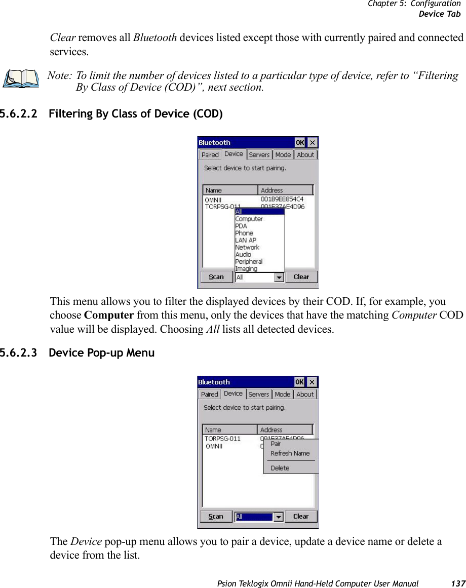
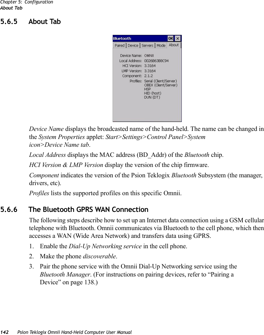
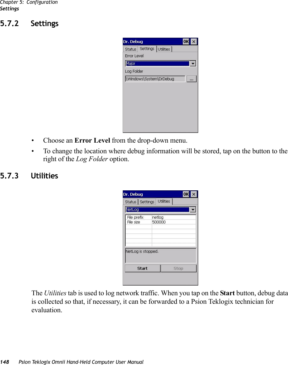
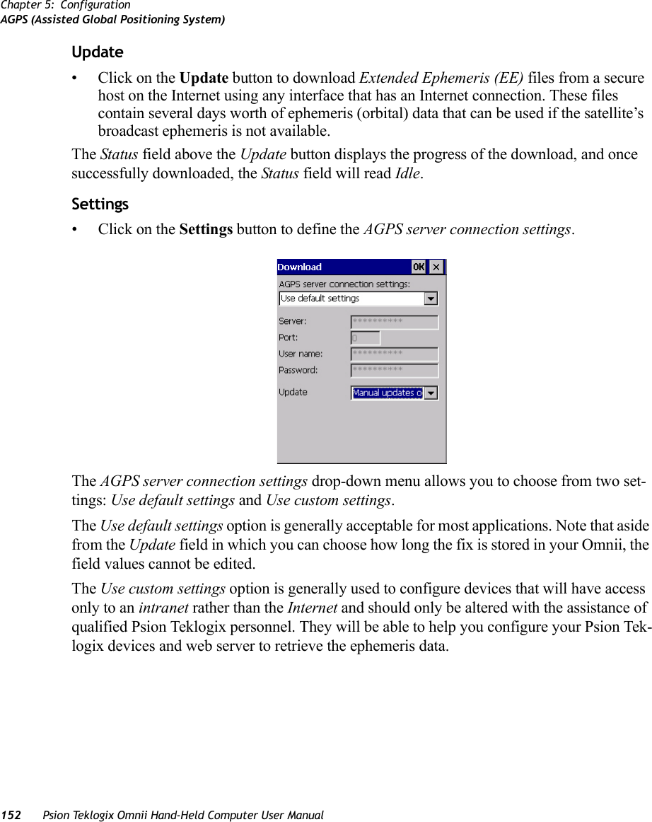
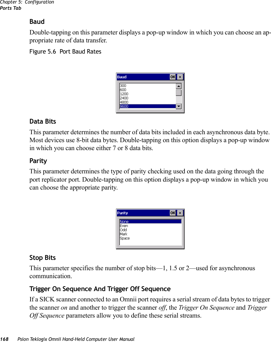
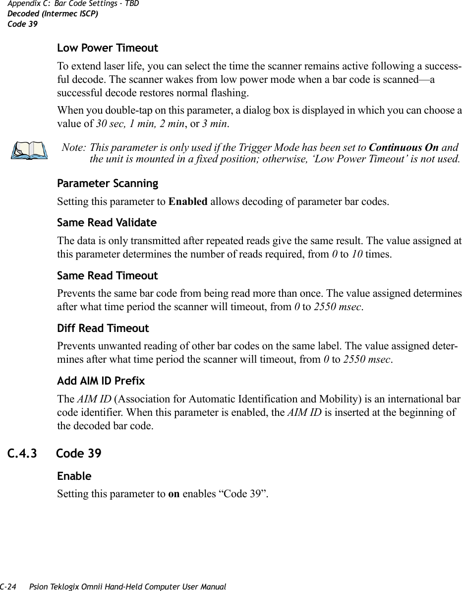
![Chapter 5: ConfigurationMode TabPsion Teklogix Omnii Hand-Held Computer User Manual 141OBEX OPP server enables the Object Push Profile server. A warm reset must be performed on Omnii after a change is made to this option. The OPP Server allows other Bluetooth devices to send files to this device.• Tap on the checkbox to activate the server.5.6.4 Mode TabTurn on Bluetooth activates the Bluetooth radio.Discoverable determines whether Omnii is visible or invisible to other devices.Printer Port allows you to assign and enable a virtual outgoing COM port selected from the drop-down menu to communicate with a paired Bluetooth printer. Keep in mind that when a port is chosen, the printer must be on and connected to the chosen port for a remote device to be able to connect.• Select a port within the Printer Port drop-down list, e.g. BSP1: • Check the Printer Port check box.•Open the Device tab and tap on Scan. • Tap-and-hold each Bluetooth Printer device entry and then select Pair, key-in the Pass-code (if needed) and then tap Done. DO NOT select any services!•Close the Bluetooth Manager.• Select the Bluetooth device to print to—you will need to key-in (or programmatically raise) the following key sequence [CTRL] [ALT] [F1].• You can now select the Bluetooth device to which you wish to print.](https://usermanual.wiki/Psion/7545MBWZ.User-Manual-2/User-Guide-1681035-Page-7.png)
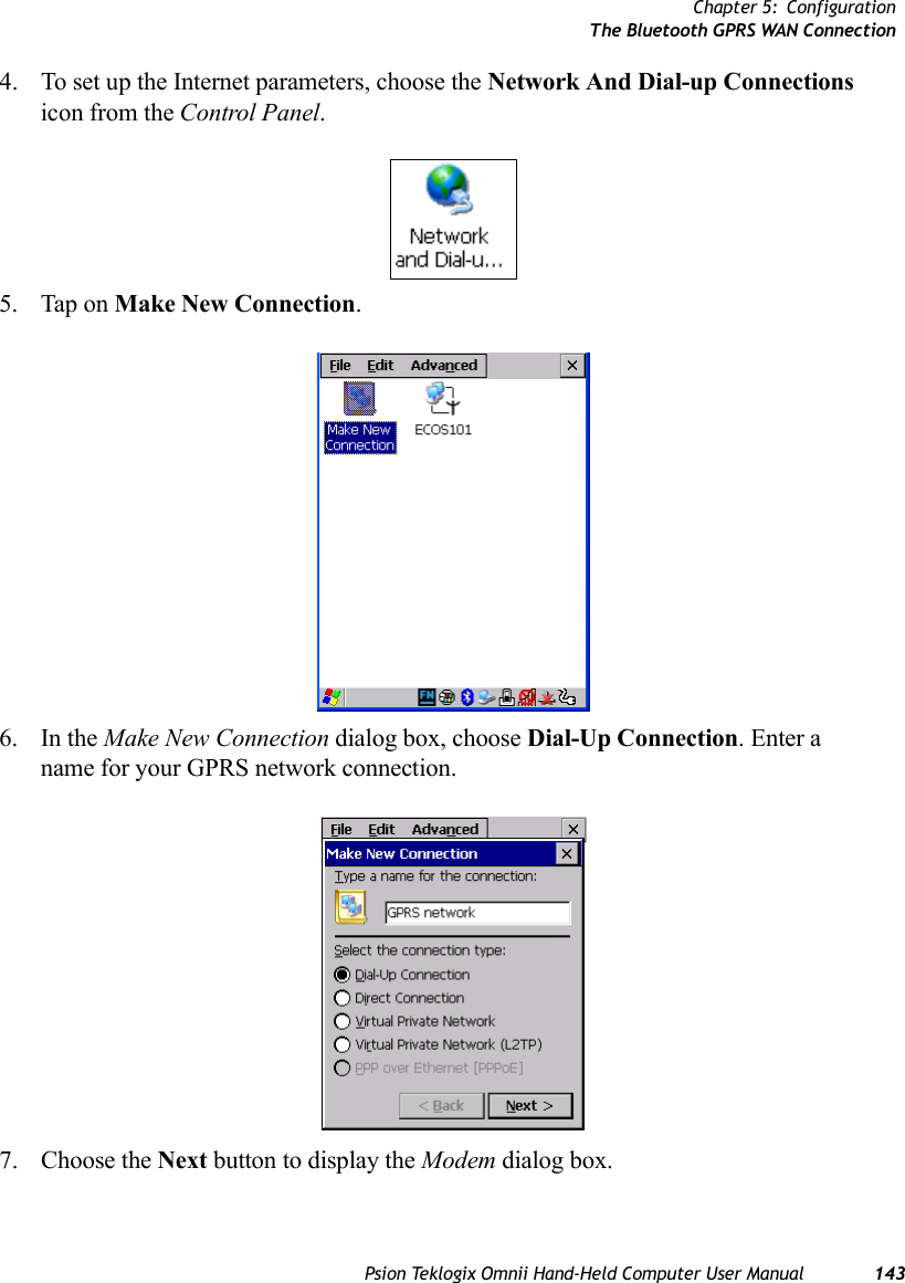
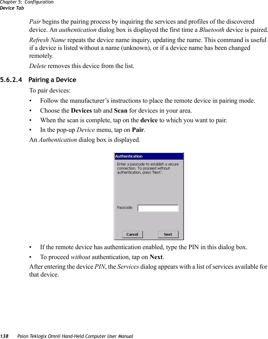
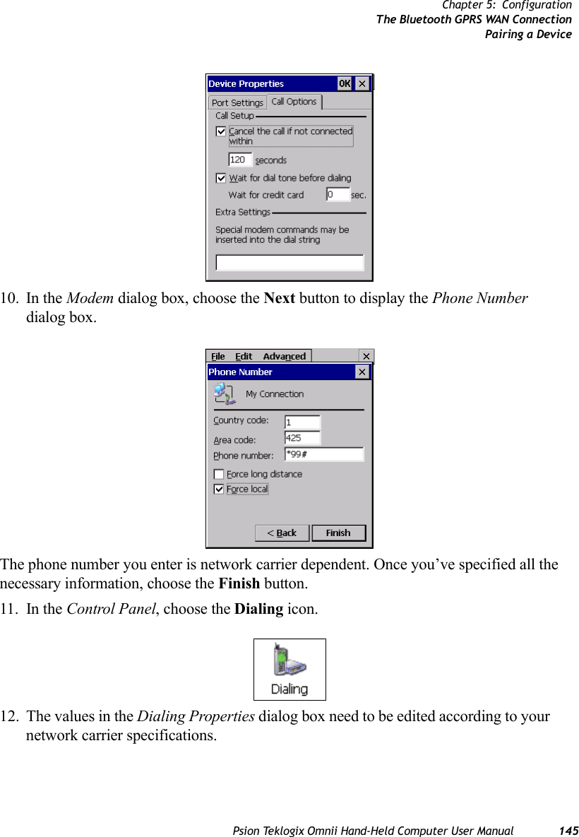
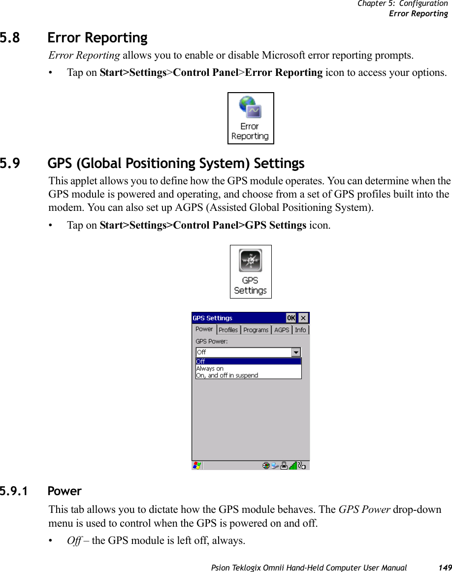
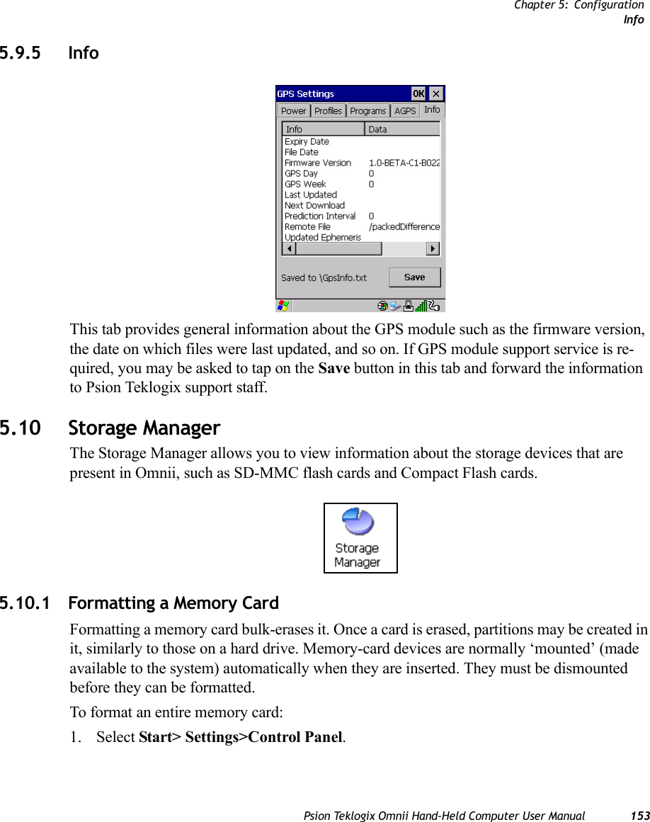
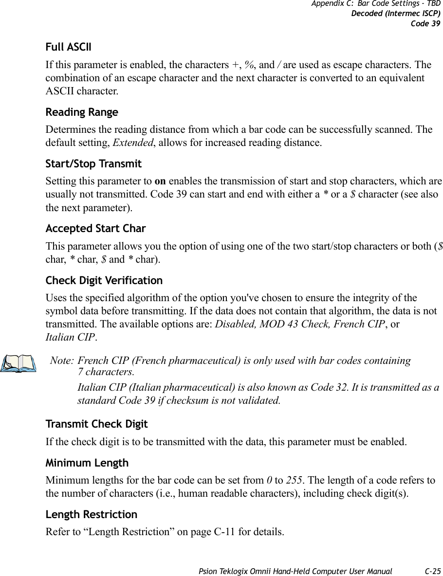
![Chapter 5: ConfigurationThe Bluetooth GPRS WAN Connection144 Psion Teklogix Omnii Hand-Held Computer User Manual8. In the drop-down menu labelled Select a modem, choose the name of the modem with which you want to connect, and then choose the Configure button to display the Device Properties dialog box.Omnii communicates via Bluetooth to your Bluetooth equipped cellular telephone and re-trieves the parameters for the Device Properties dialog box. Omnii then disconnects.9. Under the Call Options tab, turn off Cancel the call if not connected within, and press [ENTER] to save your changes.](https://usermanual.wiki/Psion/7545MBWZ.User-Manual-2/User-Guide-1681035-Page-10.png)
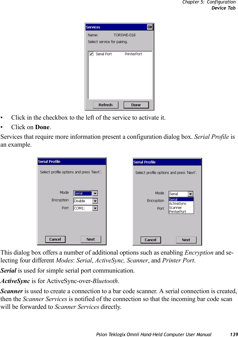
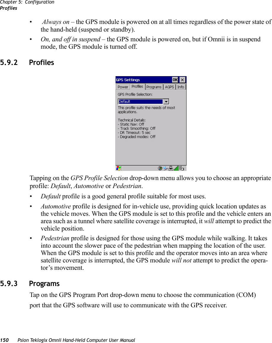
![Chapter 5: ConfigurationThe Bluetooth GPRS WAN Connection146 Psion Teklogix Omnii Hand-Held Computer User ManualOnce you’ve edited this dialog box to reflect your network carrier requirements, press [ENTER] to save your changes.13. At this point, return to the Control Panel, and choose the Network and Dial-up Connections icon.14. In the network connection window, the new network configuration—in this case, New Connection is displayed. Tap on the new icon.When you tap on your new connection, an onscreen message indicates the status of your connection: connected, disconnected, error messages, and so on.](https://usermanual.wiki/Psion/7545MBWZ.User-Manual-2/User-Guide-1681035-Page-12.png)
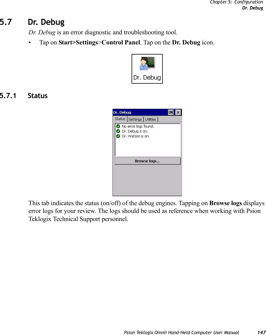
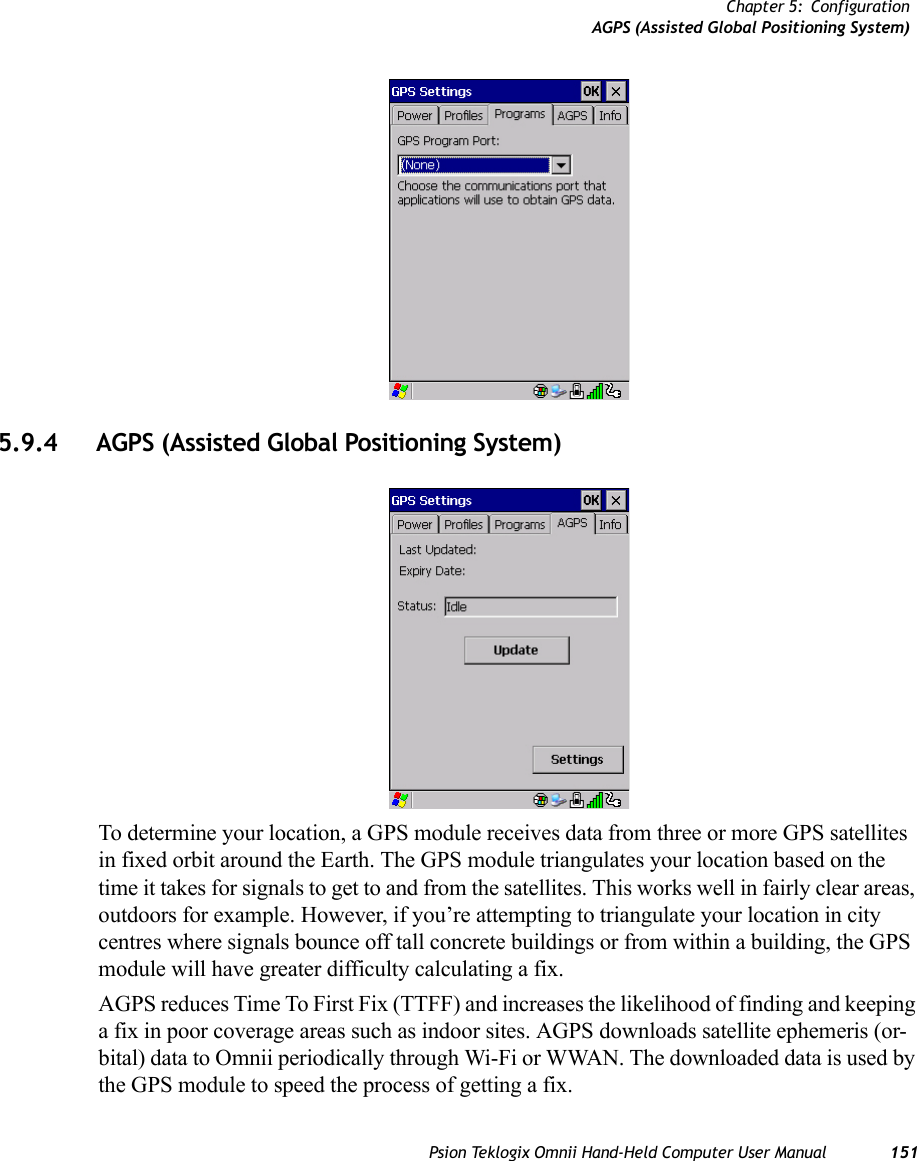
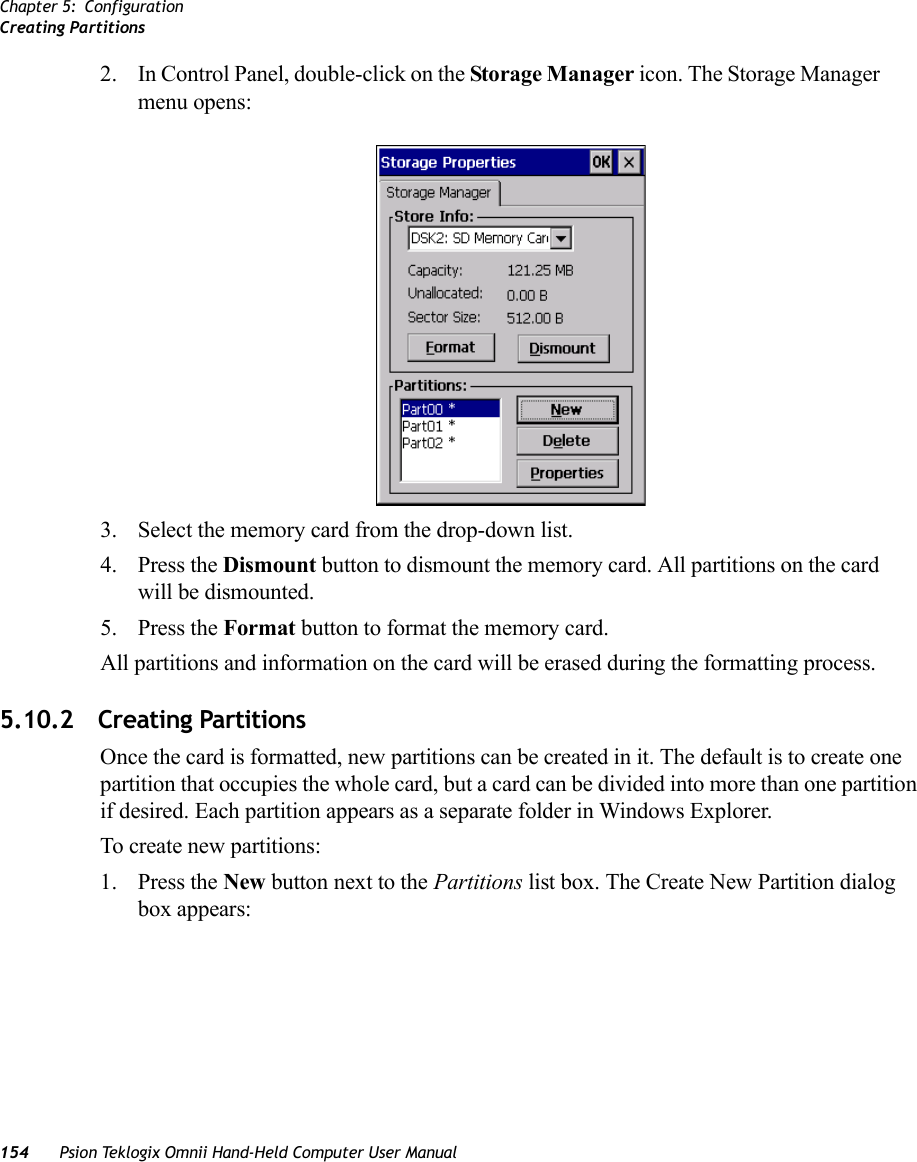

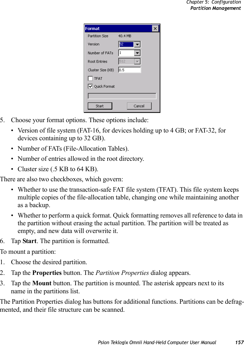
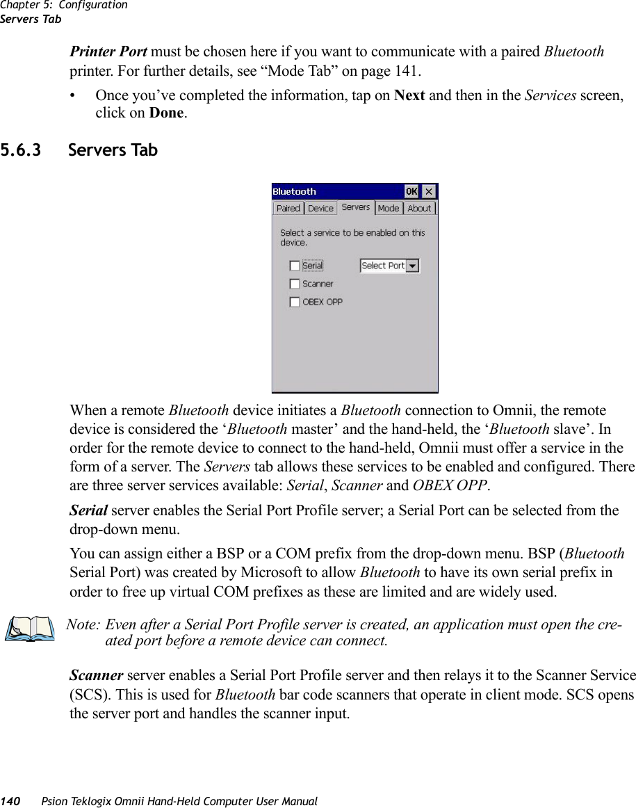
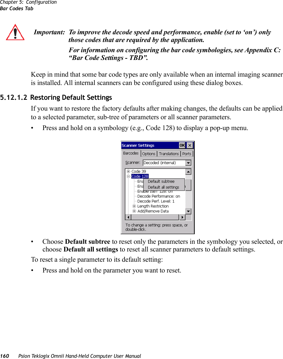
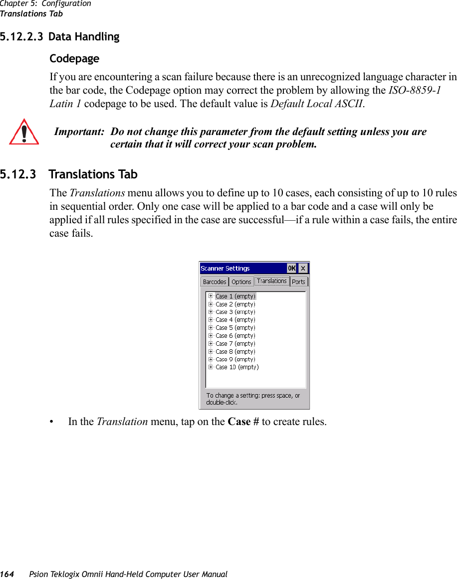
![Chapter 5: ConfigurationTek log ix Im a g er s158 Psion Teklogix Omnii Hand-Held Computer User Manual5.11 Teklogix Imagers The Teklogix Imagers applet is used to create, modify, delete, and activate imager settings. The principle uses of the applet are to decode bar codes and to capture images. A Demon-stration Application is provided to demonstrate how the imager works. Refer to “Demo” on page 71 for details. Refer to Appendix D: “Teklogix Imagers Applet” for configuration details.To launch this applet: •In the Control Panel, choose the Teklogix Imagers icon.5.12 Teklogix ScannersThe Teklogix Scanners icon in the Control Panel provides dialog boxes in which you can tailor bar code scanner configuration and choose the bar codes your scanner will recognize. Note: This icon is only displayed when the appropriate imager is installed in your Omnii. If there is an imager installed but this icon is not present, additional software (ICS) may need to be installed.To enable a newly-installed imager, Press and hold down the [FN] key and the [ENTER/Power] key simultaneously for a minimum of three seconds.](https://usermanual.wiki/Psion/7545MBWZ.User-Manual-2/User-Guide-1681035-Page-24.png)
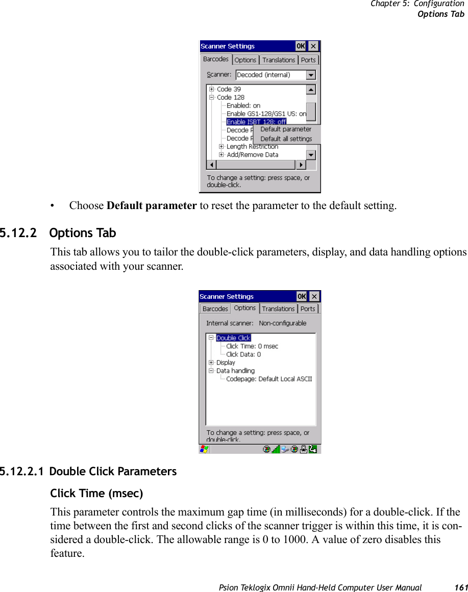
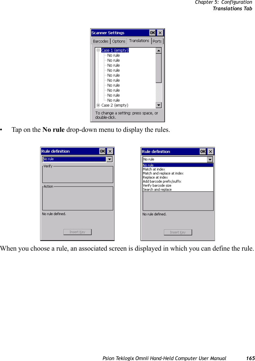
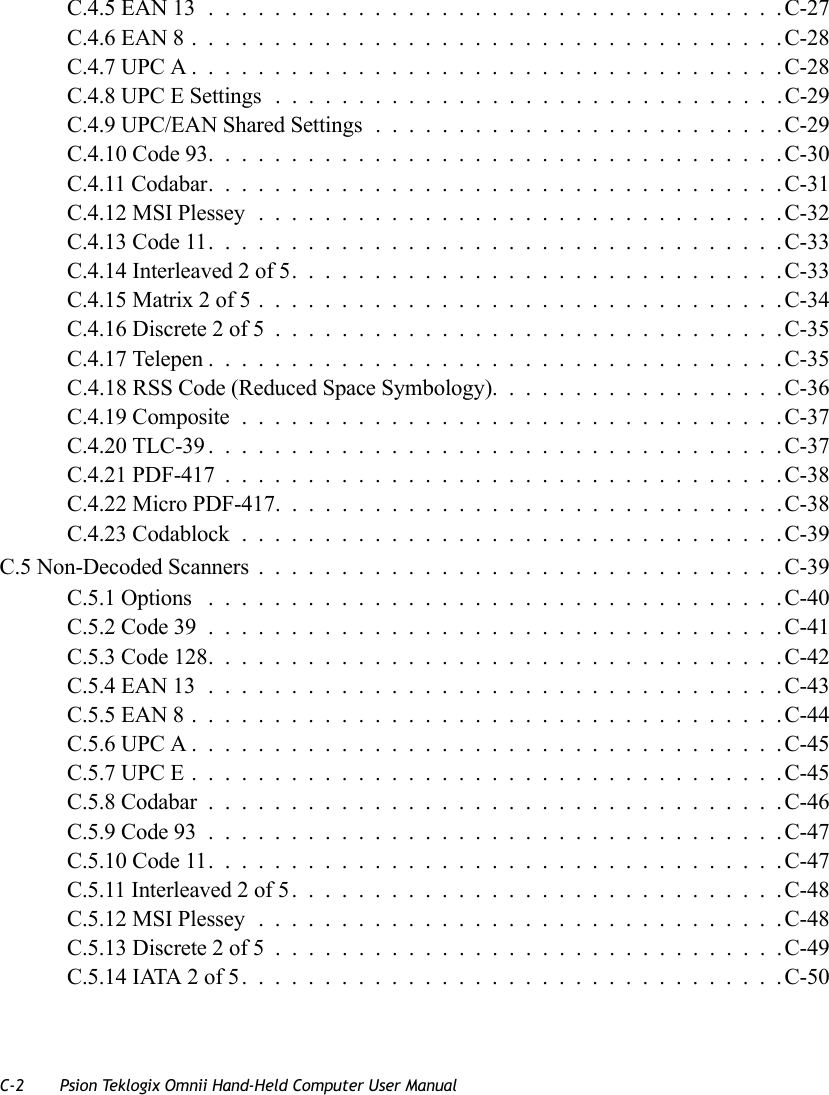
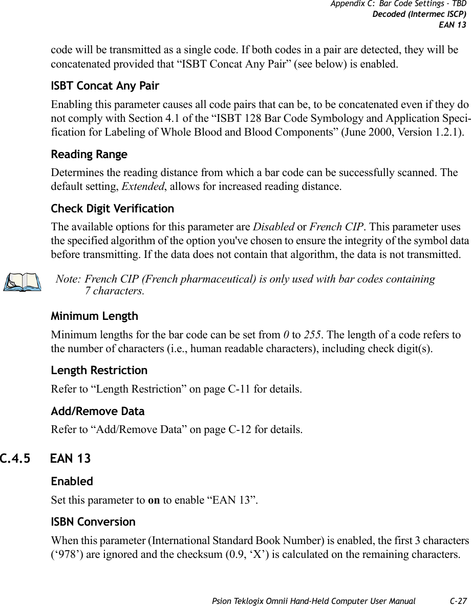
![Chapter 5: ConfigurationBar Codes TabPsion Teklogix Omnii Hand-Held Computer User Manual 159The parameters are preset with the default settings of the decoded scanner installed in the unit. For a listing of available scanners and their specifications, please refer to Chapter 7: “Specifications”. 5.12.1 Bar Codes Tab5.12.1.1 ScannerThe drop-down menu to the right of the Scanner option allows you to choose configurations for one of the following scanner types, depending on what is installed in/on your hand-held: Decoded (internal), Decoded (Intermec ISCP), Imager and Non-decoded.The symbologies listed in the Barcodes tab change to reflect the scanner you choose and the bar codes it supports. Always defer to your bar code scanner’s programming manual when in doubt about the availability or settings for any parameter. Note: To enable a newly-installed scanner, press and hold down the [FN] key and the [ENTER/Power] key simultaneously for a minimum of three seconds. Note: Your Omnii comes preconfigured from the factory for internal scanner types. The type of scanner installed can be determined from the System icon in the Control Panel, under the System Properties tab.](https://usermanual.wiki/Psion/7545MBWZ.User-Manual-2/User-Guide-1681035-Page-25.png)
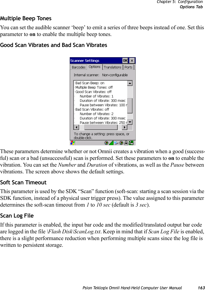
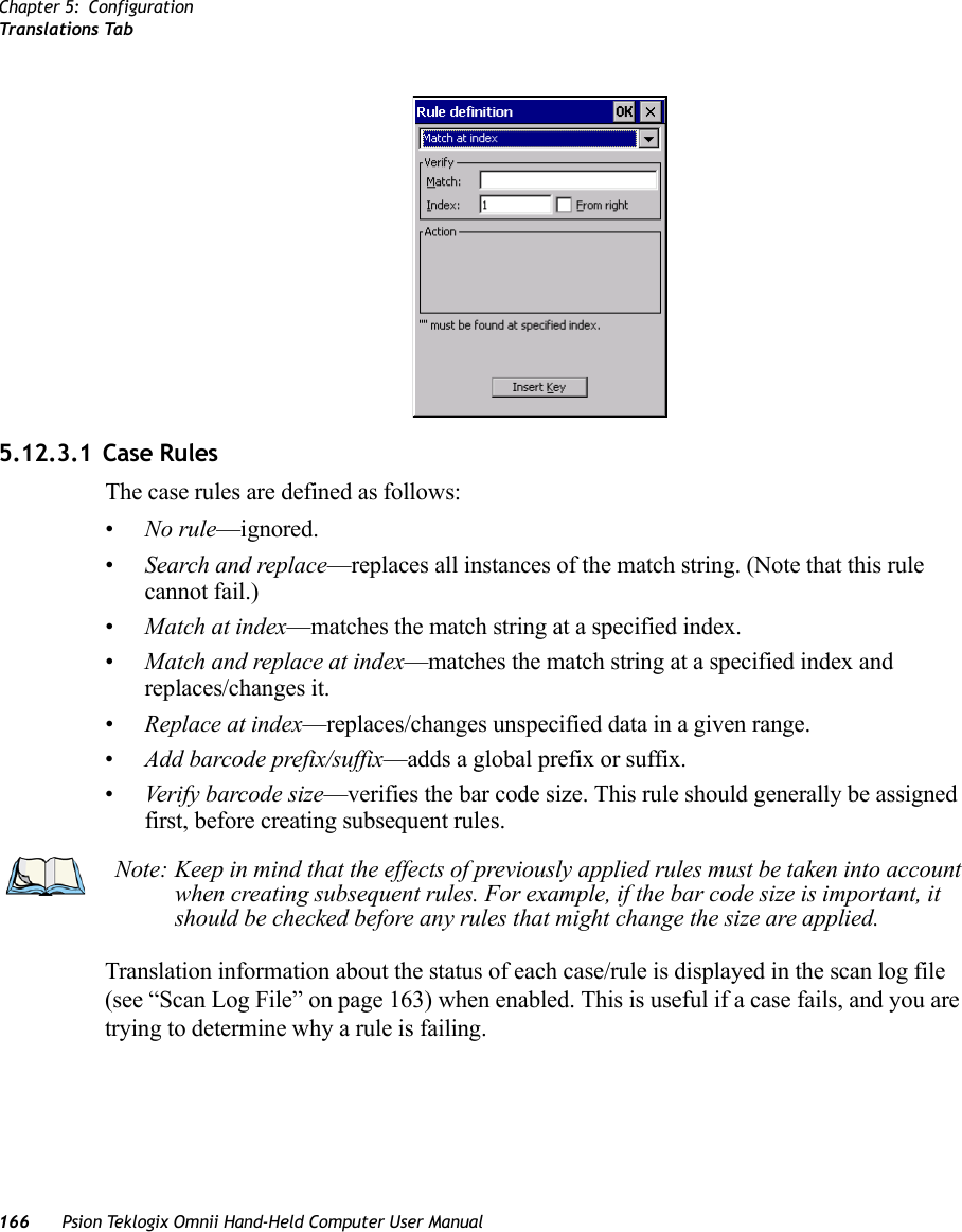
![Chapter 5: ConfigurationOptions Tab162 Psion Teklogix Omnii Hand-Held Computer User ManualA double-click produces different results depending on whether or not a value is assigned in the “Click Data” parameter. When a value is not assigned for the “Click Data”, double-click-ing the scanner trigger overrides the target dot delay set in the “Dot Time” parameter and initiates a normal scan sweep. If a value is assigned for the “Click Data” parameter, double-clicking the scanner trigger inserts the “Click Data” value rather than initiating a scan.Click DataThis parameter determines which character is sent to the application installed in your Omnii following a double-click. A dialog box appears, asking that you press the key you want to insert. The ASCII/Unicode key value of the keypress is displayed. Pressing the [ESC] key in this dialog box resets the data to zero.5.12.2.2 Display ParametersScan ResultWhen this parameter is enabled, the type of bar code and the result of the scan appear on the screen. Note that this information is only displayed after a successful decode and is visible only while the scanner trigger is pressed. When the trigger is released, this information is cleared from the screen.Scan IndicatorWhen this parameter is enabled, the laser warning logo appears on the display whenever the scanner is activated.Scan Result Time (sec)The value assigned to the Scan Result Time parameter determines how long the scan results of a successful scan are displayed on the screen. Time is measured in seconds, and a value of 0 (zero) disables the parameter. When you choose this option, a dialog box appears where you can enter a value.Good Scan Beep and Bad Scan Beep These parameters determine whether or not Omnii emits an audible scanner ‘beep’ when a good (successful) scan or a bad (unsuccessful) scan is performed. Set these parameters to either on to enable the beeper or off to disable it.Note: To remove the scan result from the screen before the “Result Time” has expired, point the scanner away from the bar code and press the trigger.](https://usermanual.wiki/Psion/7545MBWZ.User-Manual-2/User-Guide-1681035-Page-28.png)
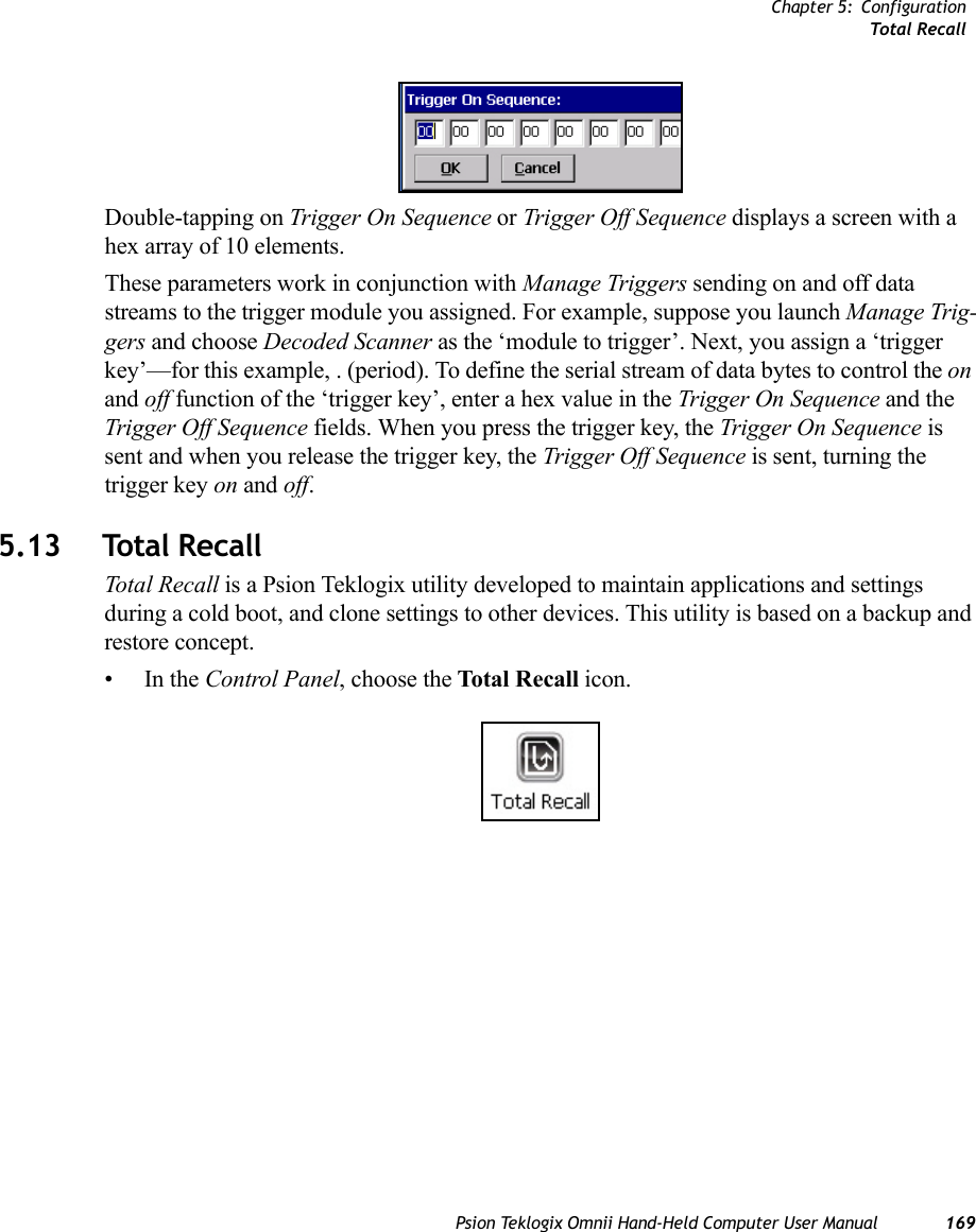
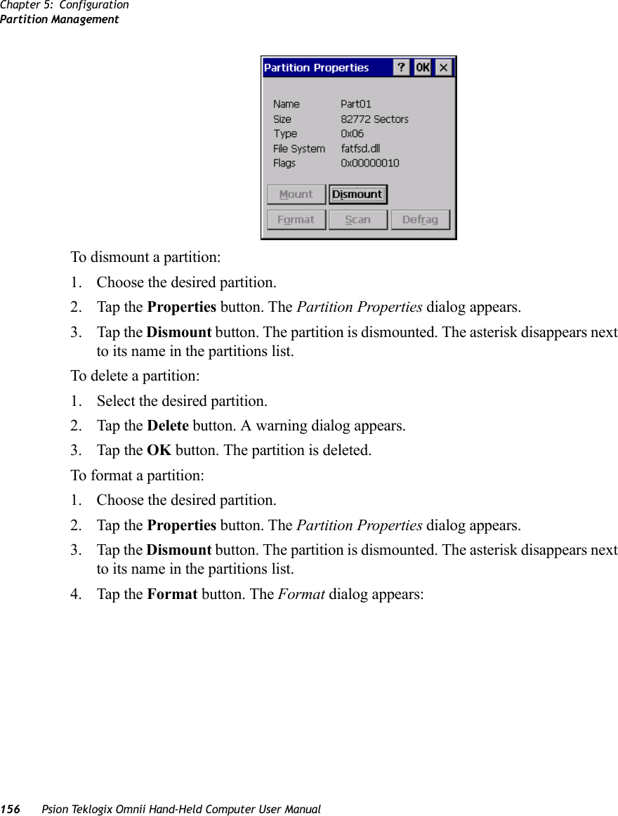
![Chapter 5: ConfigurationCreating a Backup Profile170 Psion Teklogix Omnii Hand-Held Computer User Manual5.13.1 Creating a Backup ProfileIn the start up screen, you can choose from four options: Create Profile, Restore Profile, View Profile and Delete Profile.• Tap on the Create Profile button to begin the process.Profile InformationThis dialog box displays the default profile name, the type of restore – AutoRestore or Man-ualRestore, and the possible storage destination for the profile file.• To change the Profile Name (optional), tap on the [...] button to the right of the Profile Location field.•In the Name field, type a new name. (You may need to move the onscreen keyboard down to make the Name field visible.)• Tap on OK to save the new profile name.](https://usermanual.wiki/Psion/7545MBWZ.User-Manual-2/User-Guide-1681035-Page-36.png)
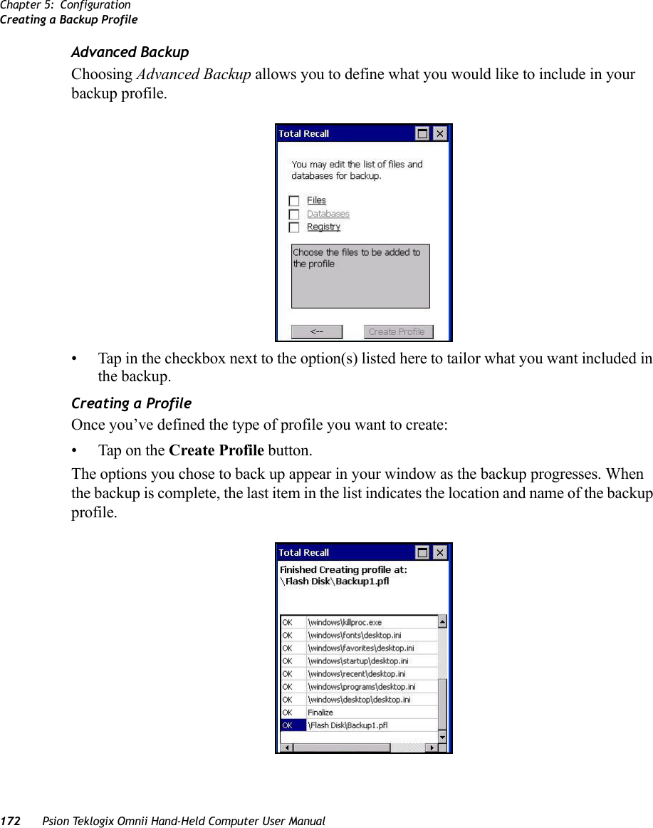
![Chapter 5: ConfigurationCreating a Backup ProfilePsion Teklogix Omnii Hand-Held Computer User Manual 171• Next, choose the profile Type you want to create:-ManualRestore – creates a backup that is manually restored by the operator.-AutoRestore – creates a profile that automatically restores itself following a cold reset or a clean reset.• Finally, if you want to choose another location for your backup file (optional), tap on the [...] button to the right of the Profile Location field.• Navigate to the new location, and tap on OK to save it.• Tap on the (Next) button. Defining the Type of BackupDefault BackupDefault Backup is selected so that all installed or copied files, database entries, and the Reg-istry are saved. Choose Advanced Backup if you want to tailor your backup.Important: Any profile not stored in persistent memory (flash disk, external usb drive) will be erased during a clean boot, therefore you should store profiles on a persistent drive. When performing an autorestore, the program only searches for profiles located in the root folder of persistent drives. If you store your profile any-where else it will not be restored. When there are multiple autorestore profiles found, only the latest is restored.](https://usermanual.wiki/Psion/7545MBWZ.User-Manual-2/User-Guide-1681035-Page-37.png)
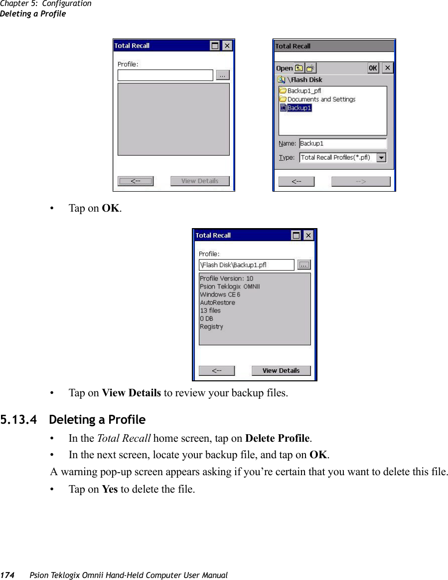
![Chapter 5: ConfigurationRestoring a ProfilePsion Teklogix Omnii Hand-Held Computer User Manual 1735.13.2 Restoring a ProfileTo manually restore a profile:•In the Total Recall home screen, tap on Restore Profile. • Tap on the [...] button to the right of the Profile field and locate your backup file.• Tap on OK.•In the Profile restore screen, click on the (Next) button. •Click on Restore Profile to restore the files to your Omnii.5.13.3 Viewing a ProfileTo view a profile:•In the Total Recall home screen, tap on View Profile. • Tap on the [...] button to the right of the Profile field, and locate your backup file.](https://usermanual.wiki/Psion/7545MBWZ.User-Manual-2/User-Guide-1681035-Page-39.png)


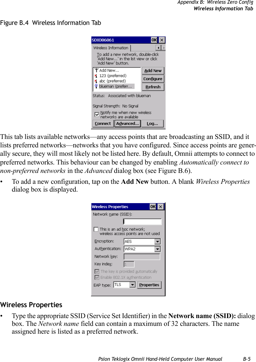
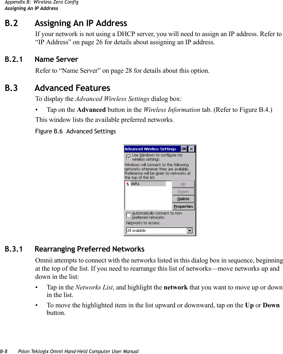
![Appendix B: Wireless Zero ConfigWireless Information TabPsion Teklogix Omnii Hand-Held Computer User Manual B-7Figure B.5 Network Key and Key Index•Key Index: This field is used to identify the WEP key. Enter a value from 1 to 4.•Enable 802.1x authentication: 802.1X is the IEEE standard that offers additional secu-rity for local area networks. It provides authentication for user devices attached to an Ethernet network, whether wired or wireless. A security protocol packet such as TLS or MD5 encapsulated in an EAP is used in conjunction with the 802.1X standard to authenticate users at the MAC layer. Available EAPs are listed in the drop-down menu next to the EAP option.To activate 802.1X, highlight 802.1x authentication, and check the checkbox.•EAP Type (Extensible Authentication Protocol): This drop-down menu lists the EAP types available on your system. The items in this drop-down menu will vary depending on your network setup. Keep in mind also that some authentication protocols require that you select a Certificate. By selecting the Properties button, you will be able to select a Certificate. “Certificates” on page 95 provides a website that outlines how to create certificates for your network.•Saving and exiting the radio setup: Once you’ve completed the configuration, press [ENTER], or tap on OK.The connection you created will be listed in the Wireless Information tab as a preferred network. The radio will search for the SSID and compare the WEP and authentication information you specified. If there is a match between the hand-held settings and the access point settings, the hand-held will communicate on the network through the access point.](https://usermanual.wiki/Psion/7545MBWZ.User-Manual-2/User-Guide-1681035-Page-80.png)
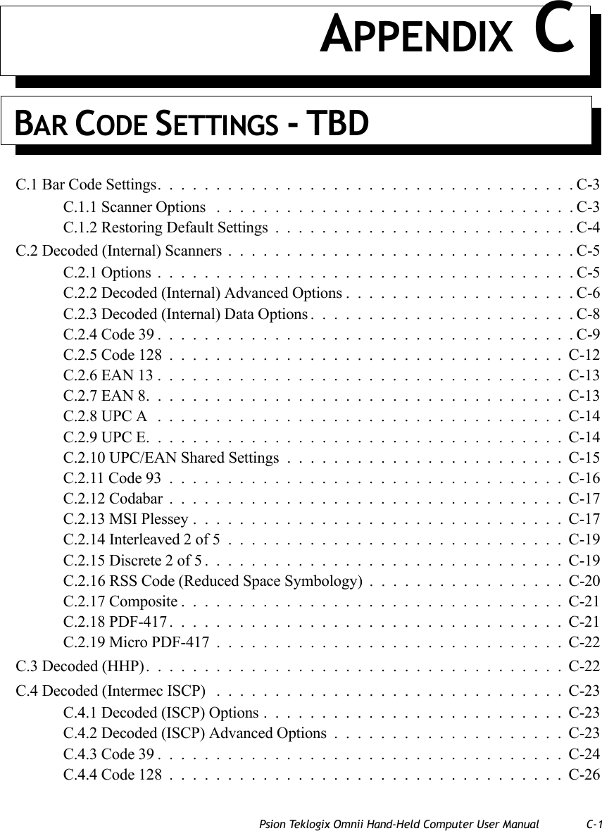
![Appendix B: Wireless Zero ConfigDeleting A Preferred NetworkPsion Teklogix Omnii Hand-Held Computer User Manual B-9B.3.2 Deleting A Preferred NetworkTo delete a network from this list:•In the preferred networks list, highlight the network you want to remove.• Tap on the Delete button.B.3.3 Changing Network PropertiesTo change the properties of an existing preferred network:• Highlight the network that you want to modify.• Tap on the Properties button.• Make any necessary changes in the Wireless Properties dialog box, and press [ENTER] to save the changes.](https://usermanual.wiki/Psion/7545MBWZ.User-Manual-2/User-Guide-1681035-Page-82.png)
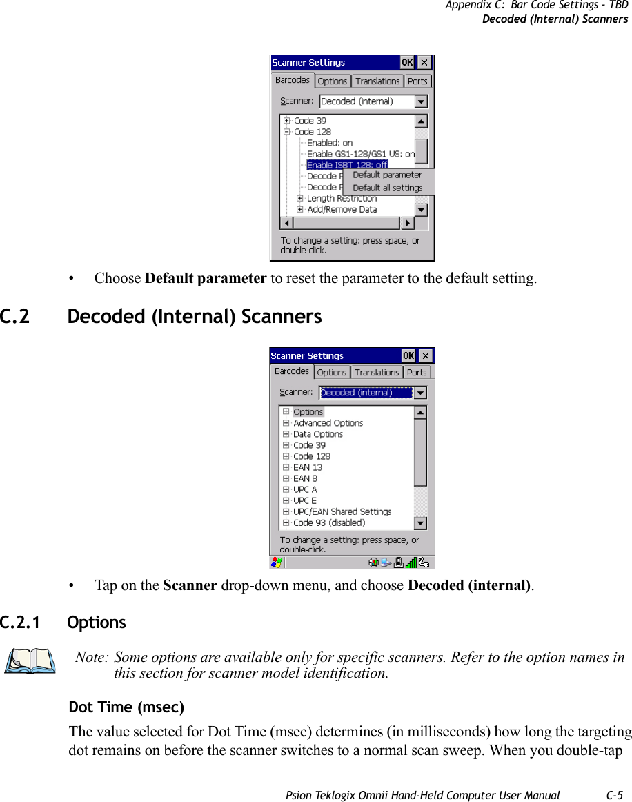
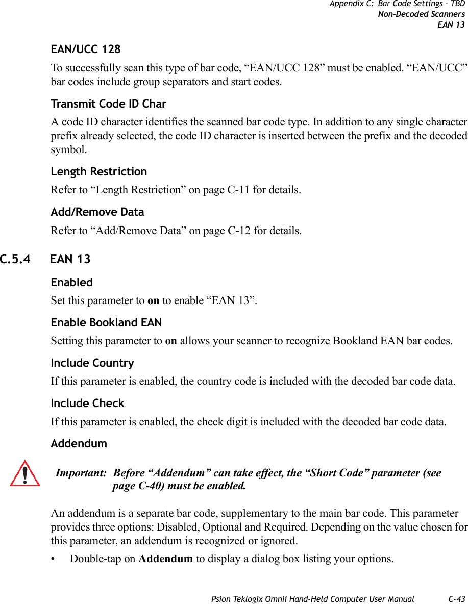
![Psion Teklogix Omnii Hand-Held Computer User Manual C-3C.1 Bar Code SettingsThe Teklogix Scanners icon in the Control Panel provides dialog boxes in which you can tailor bar code scanner configurations and choose the bar codes your scanner will recognize.The parameters are preset with the default settings of the decoded scanner installed in the unit. For a listing of available scanners and their specifications, please refer to Chapter 7: “Specifications”. C.1.1 Scanner OptionsThe drop-down menu to the right of the Scanner option allows you to choose configurations for one of the following scanner types, depending on what is installed in/on your hand-held: Decoded (internal), Decoded (HHP), Decoded (Intermec ISCP, and Non-decoded Scanners.The symbologies listed change to reflect the scanner you choose and the bar codes it sup-ports. Always defer to your bar code scanner’s programming manual when in doubt about the availability or settings for any parameter. Note: To enable a newly-installed scanner, press and hold down the [FN] key and the [ENTER/Power] key simultaneously for a minimum of three seconds. For information on configuring the Options, Translations, and Ports settings, see “Teklogix Scanners” on page 158.](https://usermanual.wiki/Psion/7545MBWZ.User-Manual-2/User-Guide-1681035-Page-86.png)
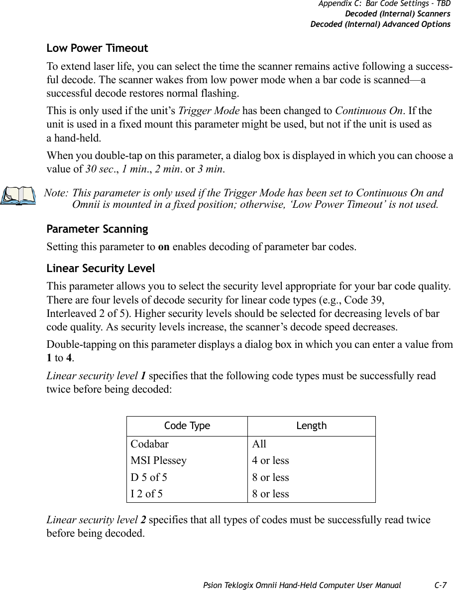
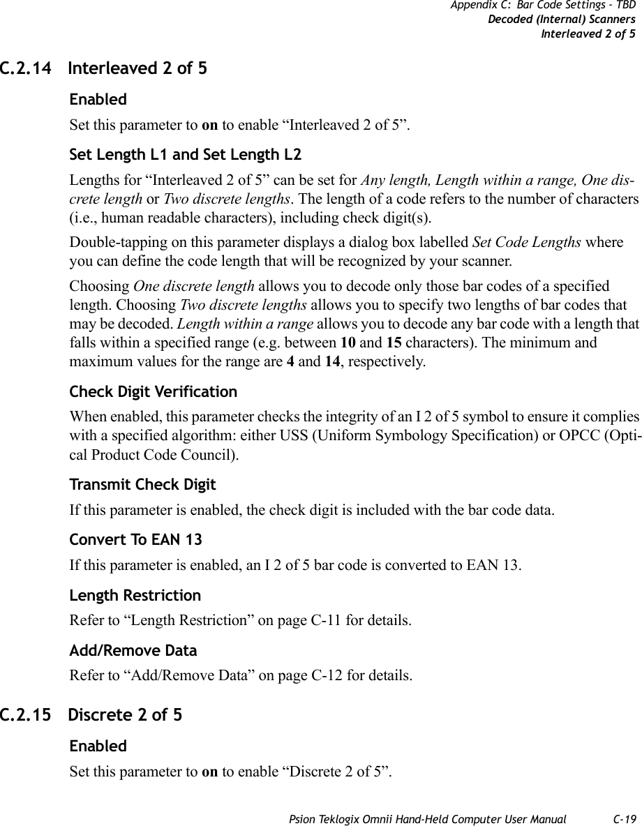
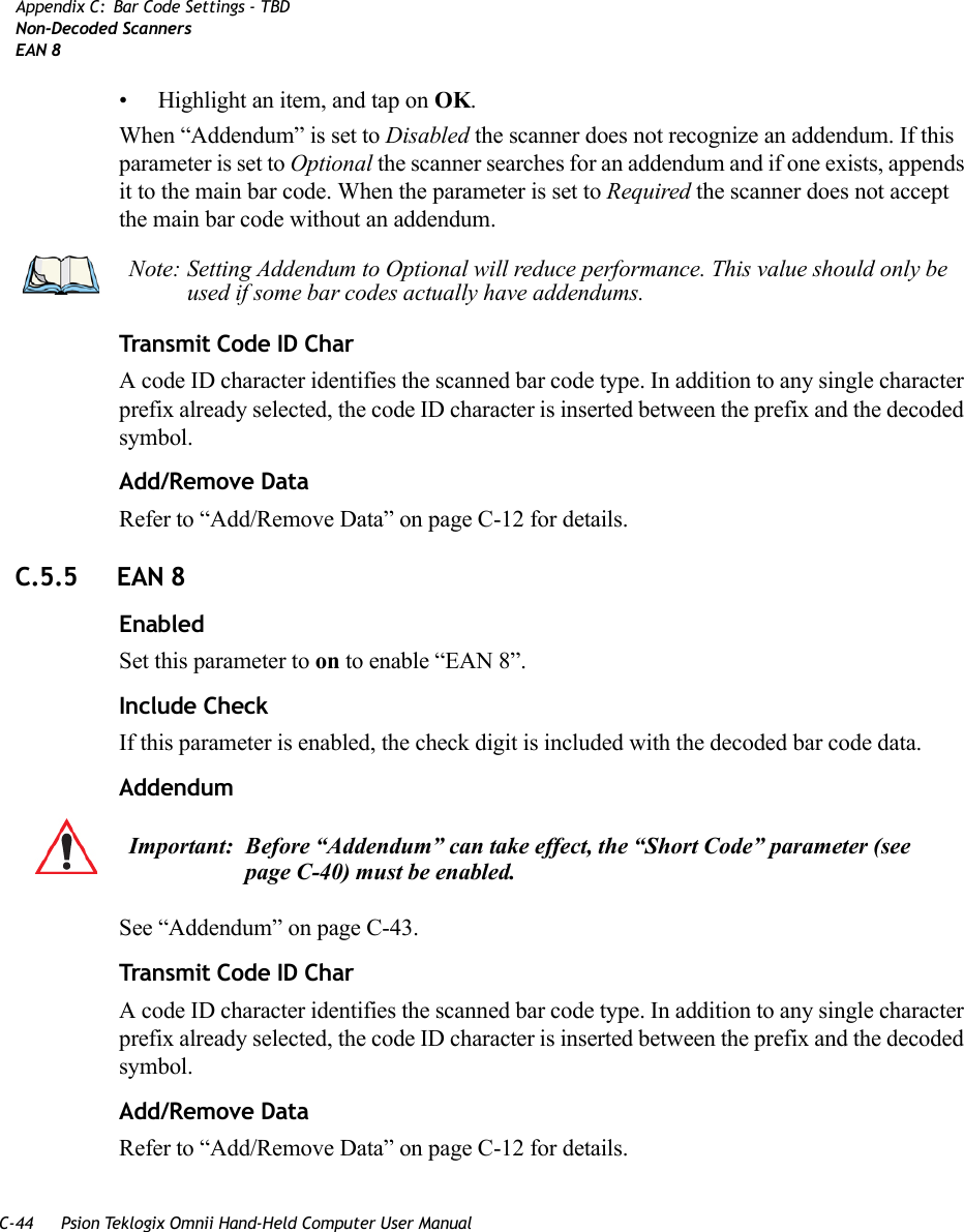
![C-8 Psion Teklogix Omnii Hand-Held Computer User ManualAppendix C: Bar Code Settings - TBDDecoded (Internal) ScannersDecoded (Internal) Data OptionsLinear security level 3 specifies that code types other than the following must be success-fully read twice before being decoded. The following codes must be read three times:Linear security level 4 requires that all code types be successfully read three times before being decoded.Bi-Direction RedundancyWhen this parameter is enabled, a bar code must be successfully scanned in both directions (forward and reverse) before being decoded.C.2.3 Decoded (Internal) Data OptionsTransmit Code ID CharA code ID character identifies the scanned bar code type. In addition to any single character prefix already selected, the code ID character is inserted between the prefix and the decoded symbol.When you double-tap on this parameter, a dialog box is displayed in which you can choose a transmit code: None, AIM or Symbol.Scan Data FormatThis parameter allows you to change the scan data transmission format.Double-tapping on Scan Data Format displays the following options from which you can choose a data format: data (as-is), data [S1], data [S2], data [S1][S2], [P] data, [P] data [S1], [P] data [S2] and [P] data [S1][S2].Code Type LengthMSI Plessey 4 or lessD 2 of 5 8 or lessI 2 of 5 8 or lessNote: This parameter is only valid if a “Linear Security Level” is enabled.](https://usermanual.wiki/Psion/7545MBWZ.User-Manual-2/User-Guide-1681035-Page-91.png)
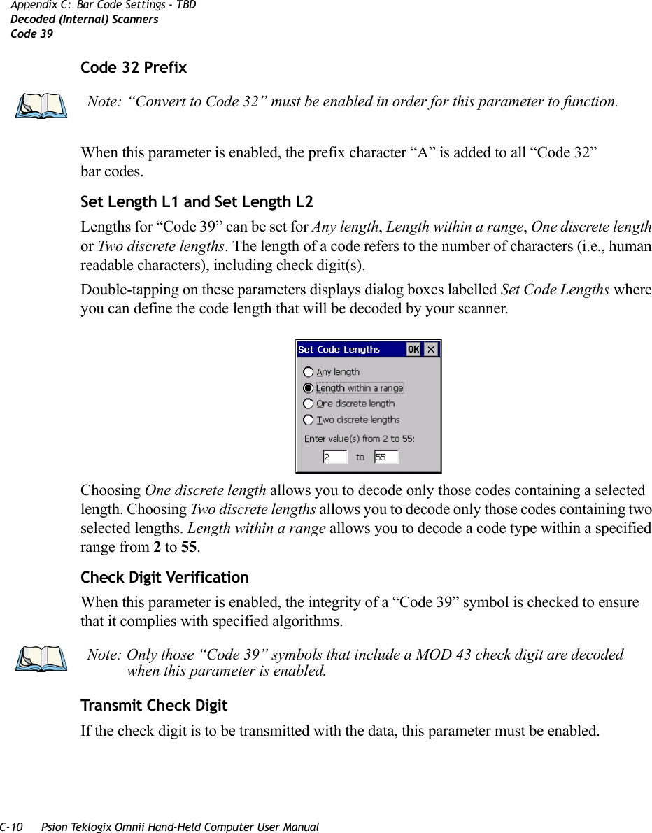
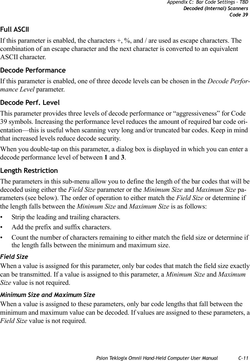
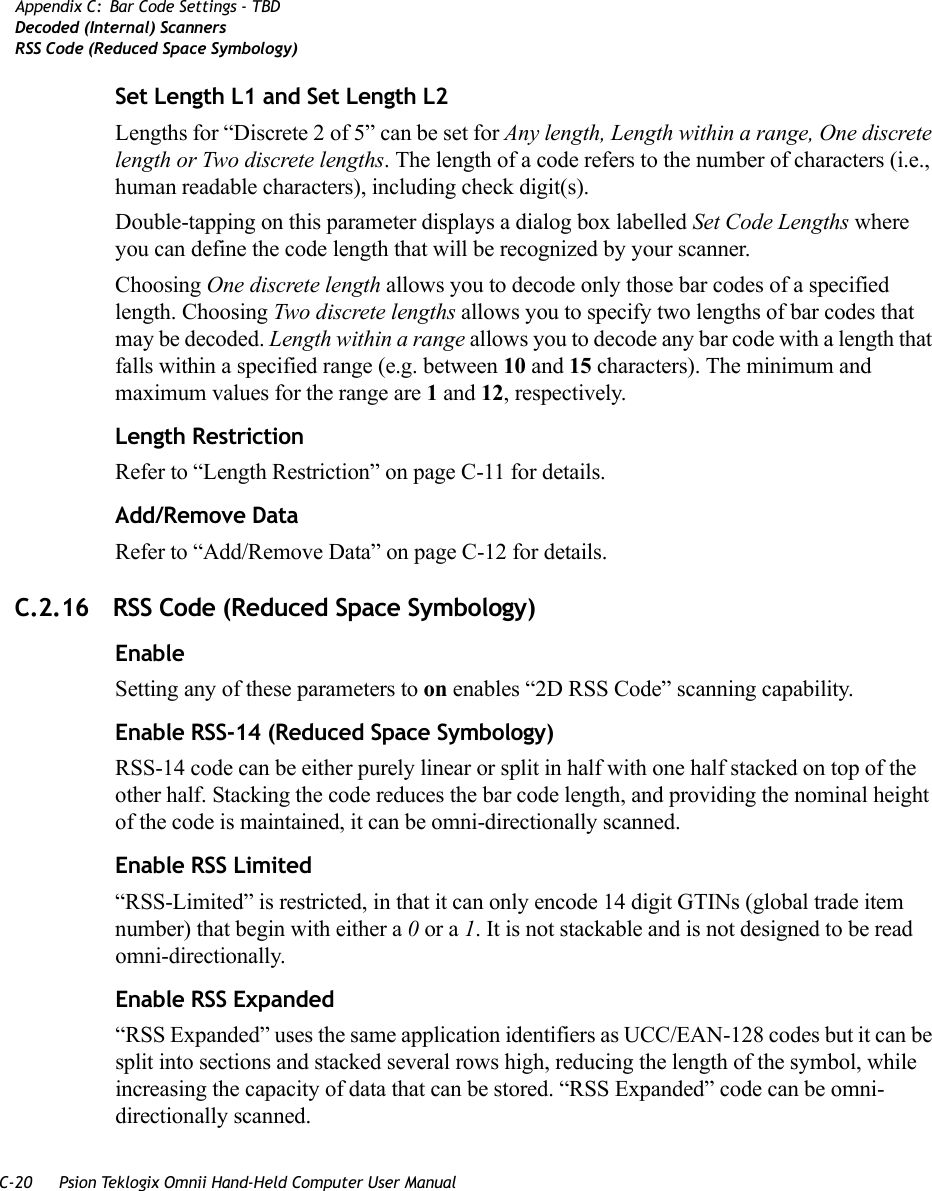
![Psion Teklogix Omnii Hand-Held Computer User Manual C-9Appendix C: Bar Code Settings - TBDDecoded (Internal) ScannersCode 39Prefix [P], Suffix [S1] and Suffix [S2]A prefix and/or one or two suffixes may be appended to scan data for use in data editing. When you double-tap on these parameters, dialog boxes are displayed in which you can enter a value from 0 to 255.Delete Char Set ECIsSetting this parameter to on enables the scanner to delete any escape sequences representing Character Set ECIs (Extended Channel Interpretations [also known as GLIs]) from its buffer before transmission. When this parameter is enabled, the scanner transmits data from PDF417 and MicroPDF417 bar codes containing Character Set ECIs, even when the ECI Protocol is disabled.ECI Decoder Setting this parameter to on enables the scanner to interpret any Extended Channel Interpre-tations (ECIs) supported by the scanner. This parameter has no effect on symbols that were not encoded using ECIs. If this parameter is set to off and a symbol that was encoded using an ECI escape is scanned, the scanner transmits the ECI escape followed by the uninterpreted data.C.2.4 Code 39EnabledSetting this parameter to on enables “Code 39”.Enable Trioptic Code 39Trioptic Code 39 symbols always contain six characters. Setting this parameter to on allows this type of symbology to be recognized.Convert To Code 32Setting this parameter to on allows the scanner to convert the bar code from “Code 39” to “Code 32”.Note: “Trioptic Code 39” and “Full ASCII” should not be enabled simultaneously. The scanner does not automatically discriminate between these two symbologies.Note: “Code 39” must be enabled in order for this parameter to function.](https://usermanual.wiki/Psion/7545MBWZ.User-Manual-2/User-Guide-1681035-Page-92.png)
![C-22 Psion Teklogix Omnii Hand-Held Computer User ManualAppendix C: Bar Code Settings - TBDDecoded (HHP)Micro PDF-417C.2.19 Micro PDF-417 EnabledSetting this parameter to on enables “2D Micro PDF-417” bar code scanning. Micro PDF-417 is a multi-row symbology that is useful for applications requiring greater area efficiency but lower data capacity than PDF-417.Code 128 EmulationWhen this parameter is enabled, the scanner transmits data from certain Micro PDF-417 symbols as if it was encoded in Code 128 symbols. If Code 128 Emulation is enabled, the following Micro PDF-417 symbols are transmitted with one of the following prefixes:]C1 if the first codeword is 903-907, 912, 914, 915]C2 if the first codeword is 908 or 909]C0 if the first codeword is 910 or 911If Code 128 Emulation is set to off, the Micro PDF-417 symbols are transmitted with one of the following prefixes:]L3 if the first codeword is 903-907, 912, 914, 915]L4 if the first codeword is 908 or 909]L5 if the first codeword is 910 or 911Length RestrictionRefer to “Length Restriction” on page C-11 for details.Add/Remove DataRefer to “Add/Remove Data” on page C-12 for details.C.3 Decoded (HHP)To configure imagers, please see Appendix D: “Teklogix Imagers Applet”.](https://usermanual.wiki/Psion/7545MBWZ.User-Manual-2/User-Guide-1681035-Page-105.png)
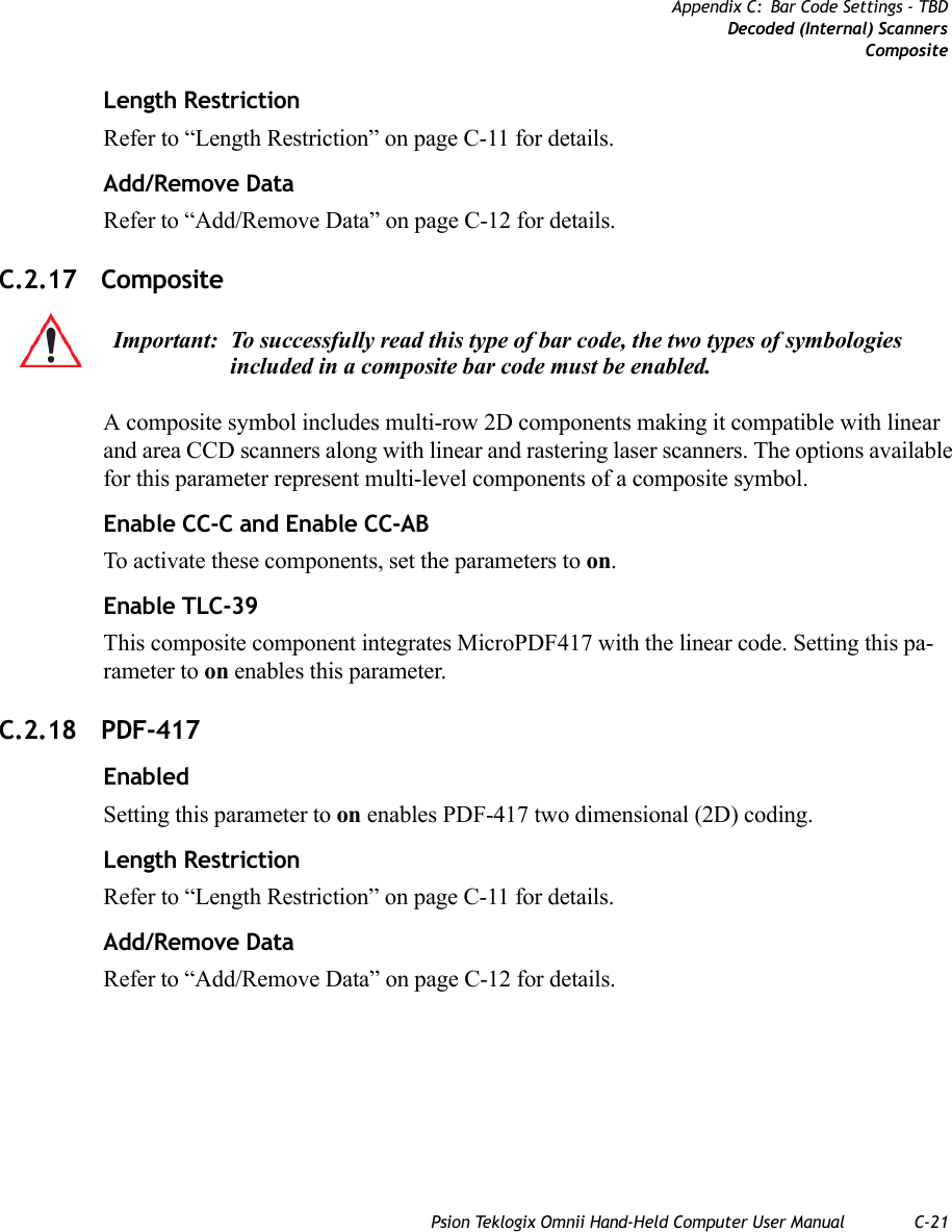
![C-26 Psion Teklogix Omnii Hand-Held Computer User ManualAppendix C: Bar Code Settings - TBDDecoded (Intermec ISCP)Code 128Add/Remove DataRefer to “Add/Remove Data” on page C-12 for details.C.4.4 Code 128EnabledSetting this parameter to on enables “Code 128”.GS1-128“GS1-128” is the GS1 implementation of the Code 128 barcode specification. The former correct name was UCC/EAN-128.GS1-128 Identifier“GS1-128 Identifier” allows the AIM ID “ ]C1” for EAN 128 to be transmitted or removed. By default, this identifier is transmitted if EAN 128 is enabled.GTIN CompliantGTIN (global trade item number) processing transmits EAN 128 as the 14-character EAN/UCC GTIN. To use GTIN processing, you must activate the EAN 128 symbology.FNC1 Conversion“FNC1 Conversion” allows the FNC1 character to be converted to another character for ap-plications that cannot use the default <GS> Group Separator or hex (1d). Double-tapping on this option displays a dialog box listing the allowable range: 0 to 255. Enable ISBT 128 To successfully scan this type of bar code (International Society of Blood Transfusion), this option must be set to on. If you enable this type of bar code, Code 128/EAN 128 is deacti-vated to avoid any confusion.ISBT Concat TransmitThe codes are not concatenated by default. You need to choose one of the options provided for this parameter to send concatenated code. Choosing Only Concatenated Codes transmits only concatenated codes—single codes will not be transmitted. Choosing Concatenated or Single transmits single codes or concatenated codes. If only one code of a pair is read, that Important: When EAN 128 and GTIN processing are both activated, it is not possible to read normal EAN 128 Codes.](https://usermanual.wiki/Psion/7545MBWZ.User-Manual-2/User-Guide-1681035-Page-109.png)
![C-38 Psion Teklogix Omnii Hand-Held Computer User ManualAppendix C: Bar Code Settings - TBDDecoded (Intermec ISCP)PDF-417Add/Remove DataRefer to “Add/Remove Data” on page C-12 for details.C.4.21 PDF-417EnabledSet this parameter to on to enable “2D PDF-417”.Length RestrictionRefer to “Length Restriction” on page C-11 for details.Add/Remove DataRefer to “Add/Remove Data” on page C-12 for details.C.4.22 Micro PDF-417EnabledSet this parameter to on to enable “2D Micro PDF-417”.Code 128 EmulationWhen this parameter is enabled, the scanner transmits data from certain Micro PDF-417 symbols as if it was encoded in Code 128 symbols. If Code 128 Emulation is enabled, the following Micro PDF-417 symbols are transmitted with one of the following prefixes:]C1 if the first codeword is 903-907, 912, 914, 915]C2 if the first codeword is 908 or 909]C0 if the first codeword is 910 or 911If Code 128 Emulation is set to off, the Micro PDF-417 symbols are transmitted with one of the following prefixes:]L3 if the first codeword is 903-907, 912, 914, 915]L4 if the first codeword is 908 or 909]L5 if the first codeword is 910 or 911Length RestrictionRefer to “Length Restriction” on page C-11 for details.](https://usermanual.wiki/Psion/7545MBWZ.User-Manual-2/User-Guide-1681035-Page-121.png)
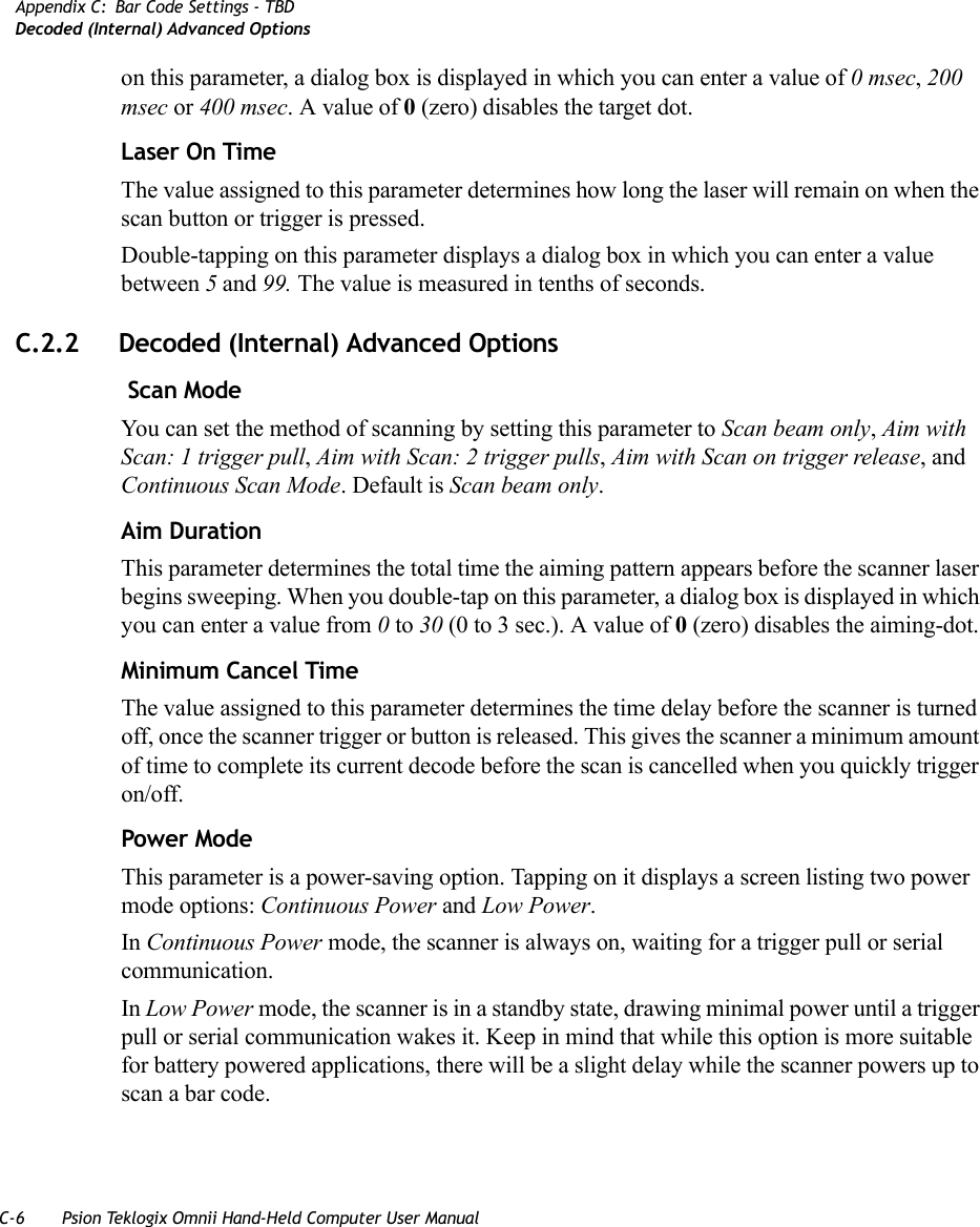
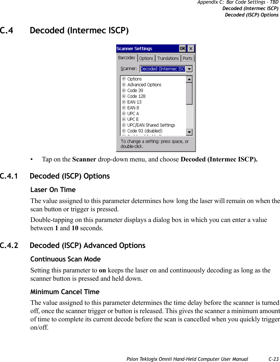
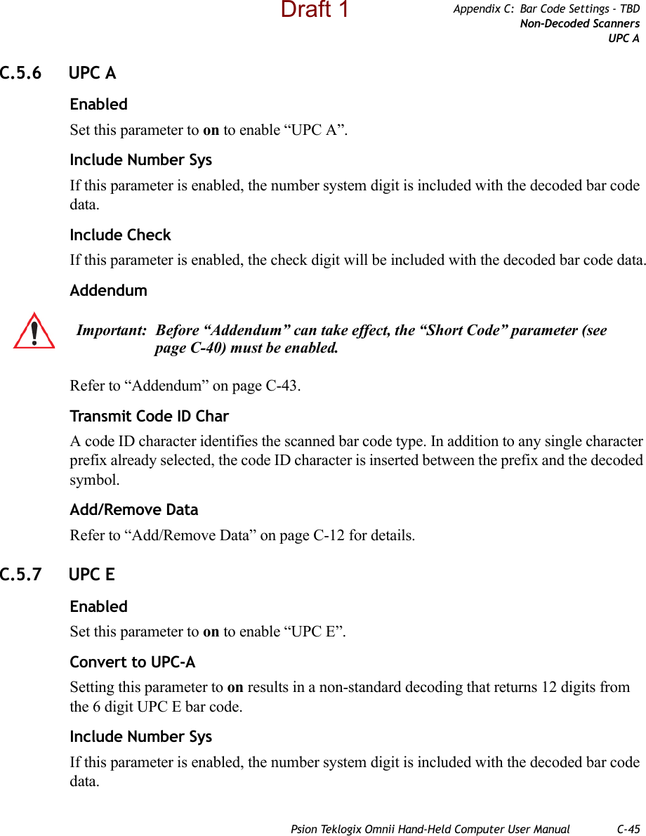
![C-40 Psion Teklogix Omnii Hand-Held Computer User ManualAppendix C: Bar Code Settings - TBDNon-Decoded ScannersOptions• To change a parameter value, double-tap on the parameter. If you need to type a value, a dialog box is displayed in which you can type a new value. If you need to change a yes or no value, double-tapping on the parameter toggles between yes and no.If you’re using the keyboard:• Highlight the bar code you want to work with, and press the [RIGHT] arrow key to display the sub-menu.• Use the [UP] and [DOWN] arrow keys to highlight a parameter. • To change a parameter value, press [SPACE] or the [RIGHT] arrow key. If a field requires text entry, a text box is displayed in which you can enter the appropriate value.C.5.1 Options• Tap on the + sign next to Options to display these parameters.Dot Time (msec)The value selected for “Dot Time (msec)” determines (in milliseconds) how long the target-ing dot remains on before the scanner switches to a normal scan sweep. When you double-tap on this parameter, a dialog box is displayed in which you can enter a value from 0 to 3000. A value of 0 (zero) disables the target dot.Short CodeWhen enabled, this parameter allows scanning of short I 2 of 5 bar codes (2 characters). When disabled, these short bar codes are rejected.Enabling “Short Code” may reduce the robustness of the decoding since the hand-held must decode more potential bar codes; it is therefore not recommended for general-purpose bar codes with 4 or more characters. VerifyThe value entered for this parameter determines the number of correct additional decodes re-quired after the initial decode, prior to a bar code being accepted. Higher values significantly increase the time it takes to decode a bar code but also improve the reliability of the decoded bar code.SecurityThis parameter controls the tolerance for decoding edge-to-edge bar codes (Code 93, Code 128, UPC/EAN). Lower values have a lower tolerance for misreads, but they also increase the time it takes to decode the bar code. The default value of 30 is generally a good compro-mise setting.](https://usermanual.wiki/Psion/7545MBWZ.User-Manual-2/User-Guide-1681035-Page-123.png)
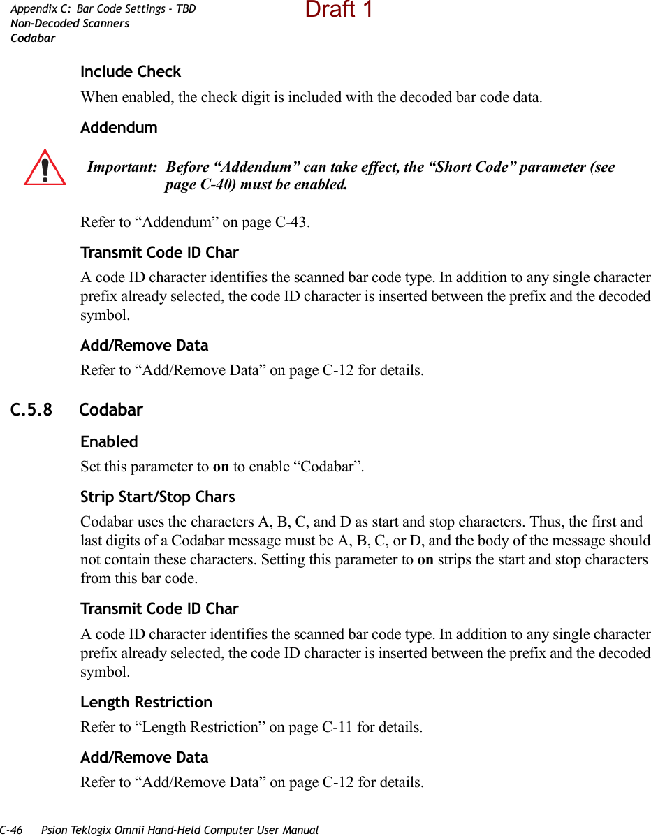
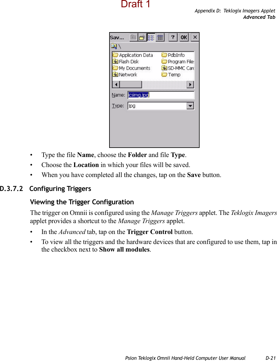
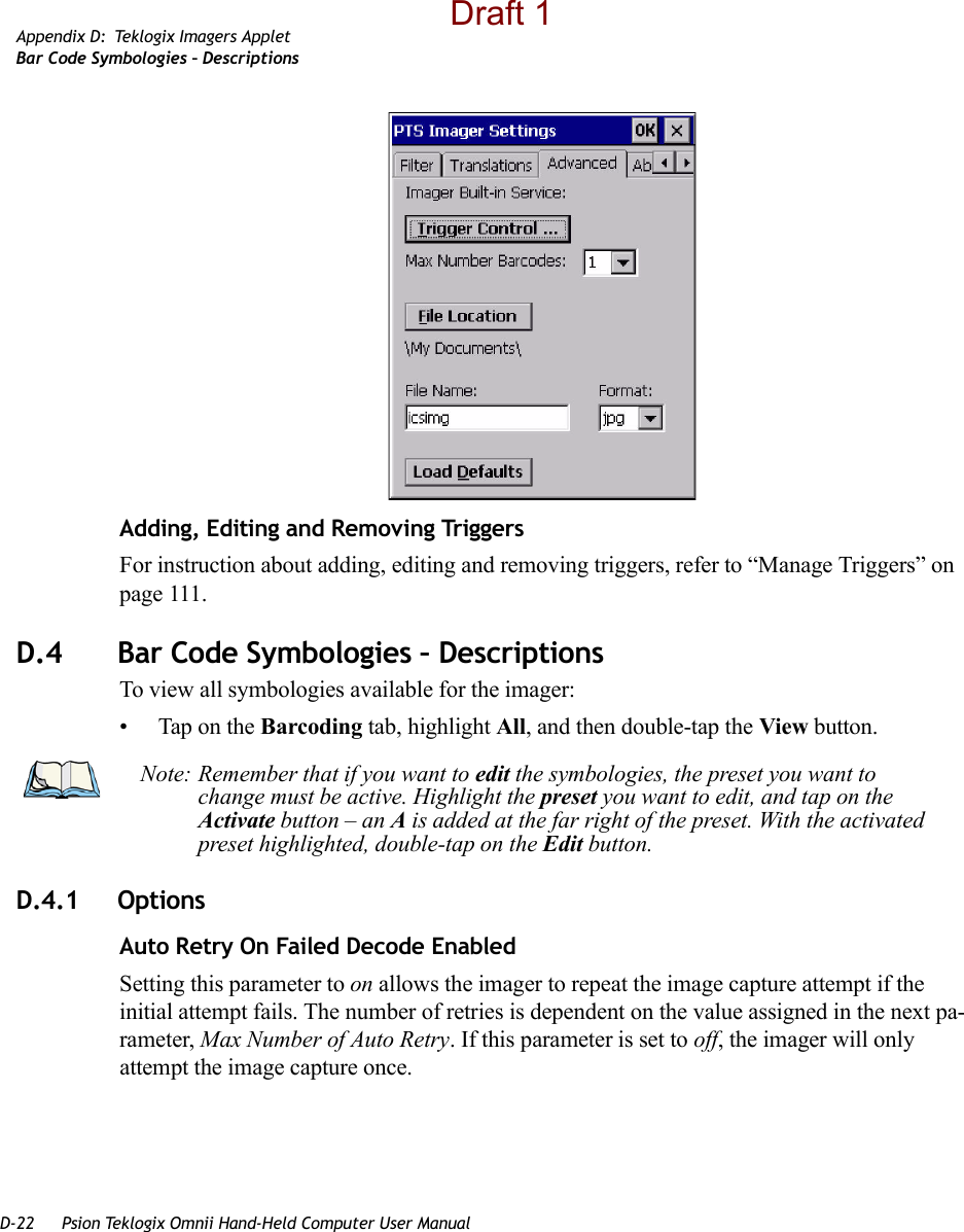
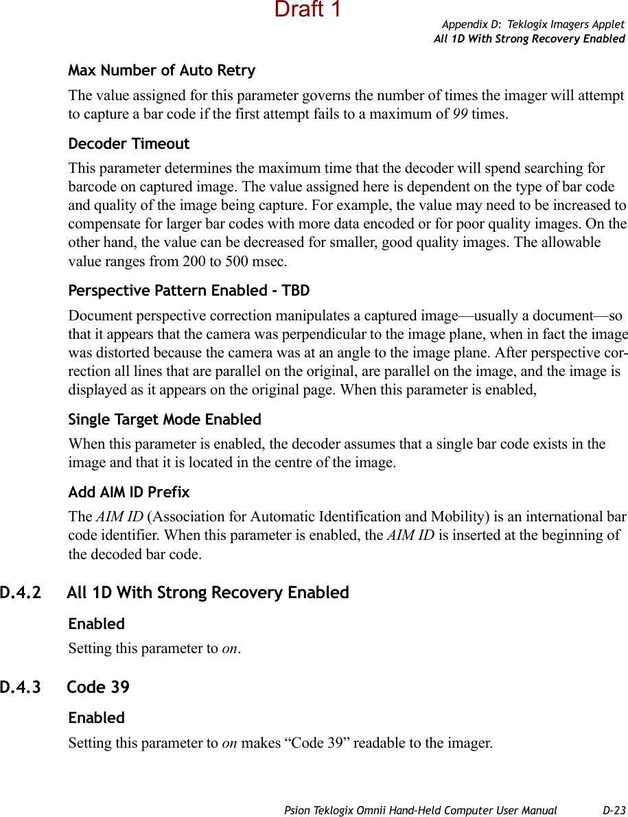
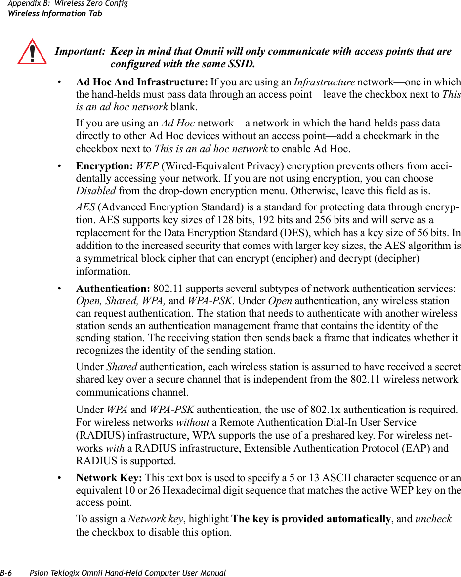
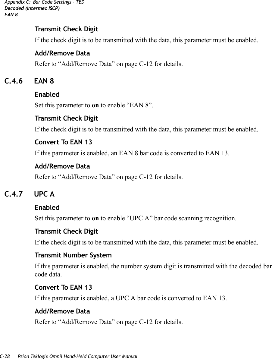
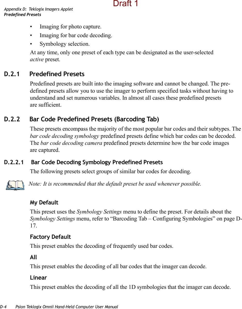
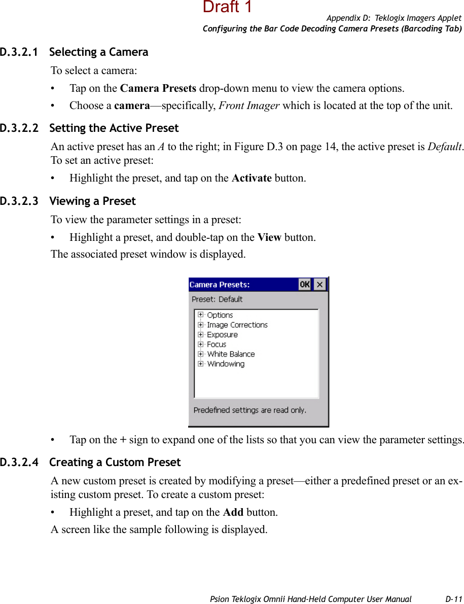
![Appendix D: Teklogix Imagers AppletRequired AppletsPsion Teklogix Omnii Hand-Held Computer User Manual D-3The Teklogix Imagers applet is used to create, modify, delete, and activate imager settings. The principal uses of the application are to decode bar codes and to capture images. This imager services application is used for cameras and imagers to configure linear (1D), stacked linear, matrix (true 2D) and postal bar codes. A Demonstration Application is pro-vided to demonstrate how the imager works. Refer to “Demo” on page 71 for details.D.1 Required AppletsIn order to configure imaging, the Manage Triggers applet must be present in the Control Panel, along with the Teklogix Imagers applet. D.2 Presets There are two methods that can be used to configure an imager using the Teklogix Imagers applet:• Use a predefined preset.• Create a custom preset based on a predefined preset.A preset is a group of exposure and image correction settings. Each preset configures the imager for a specific purpose such as bar code decoding or image capture.Presets also allow easier and faster configuration of the imager after power-on or resume from suspend.The predefined presets are generic and satisfy most user requirements. A custom preset can be created for a specific user application, such as: include only specified bar codes, read only a specified number of bar codes or for reading unusual media.Every preset belongs to a preset type. The following preset types are available:Note: The Teklogix Imagers icon is only displayed when the appropriate imager is installed in your Omnii. If there is an imager installed but this icon is not present, additional software (ICS) may need to be installed.To enable a newly-installed imager, press and hold down the [FN] key and the [ENTER/Power] key simultaneously for a minimum of three seconds. Important: It is strongly recommended that a predefined preset is used whenever possible. Each predefined preset contains a coherent group of settings that are known to work together in the intended environment. In almost all situations, at least one of the prede-fined presets results in a satisfactory outcome.Draft 1](https://usermanual.wiki/Psion/7545MBWZ.User-Manual-2/User-Guide-1681035-Page-136.png)
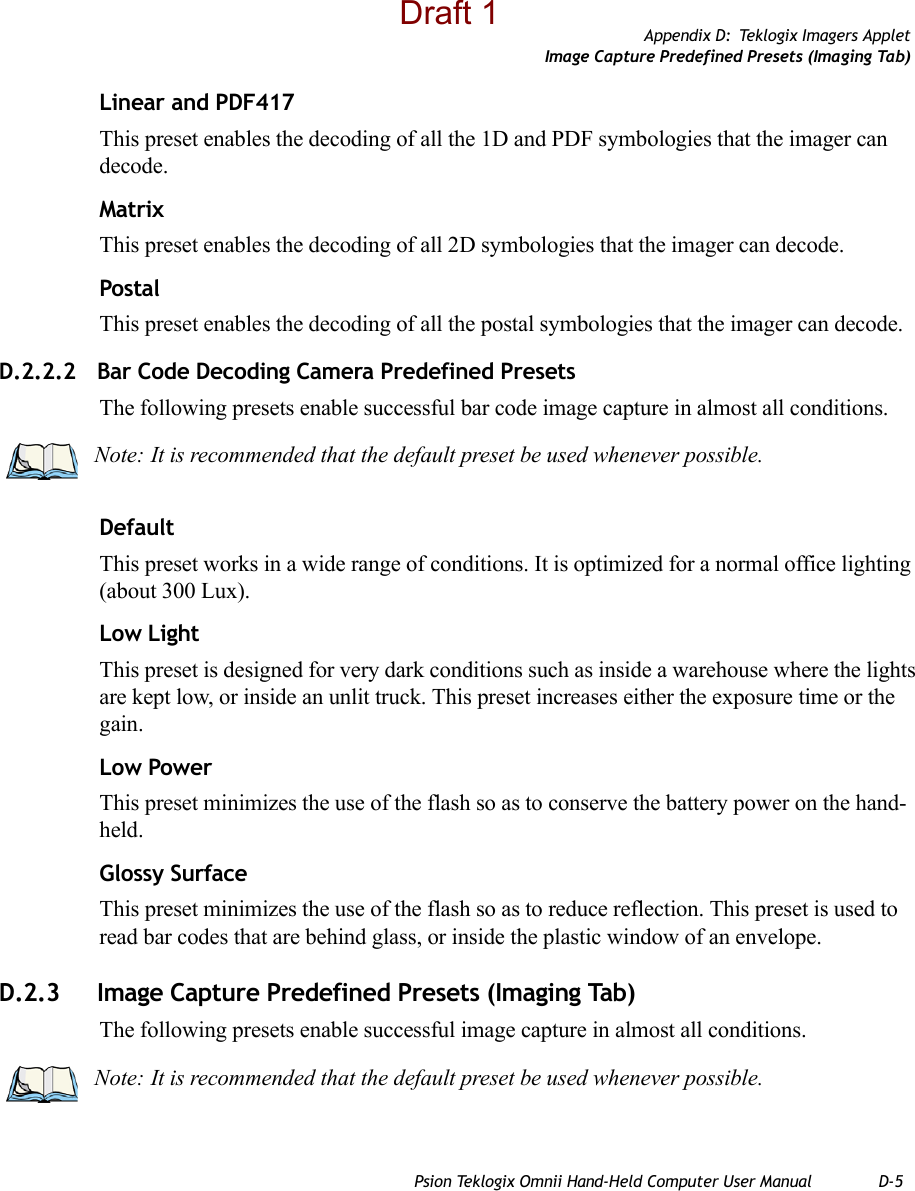
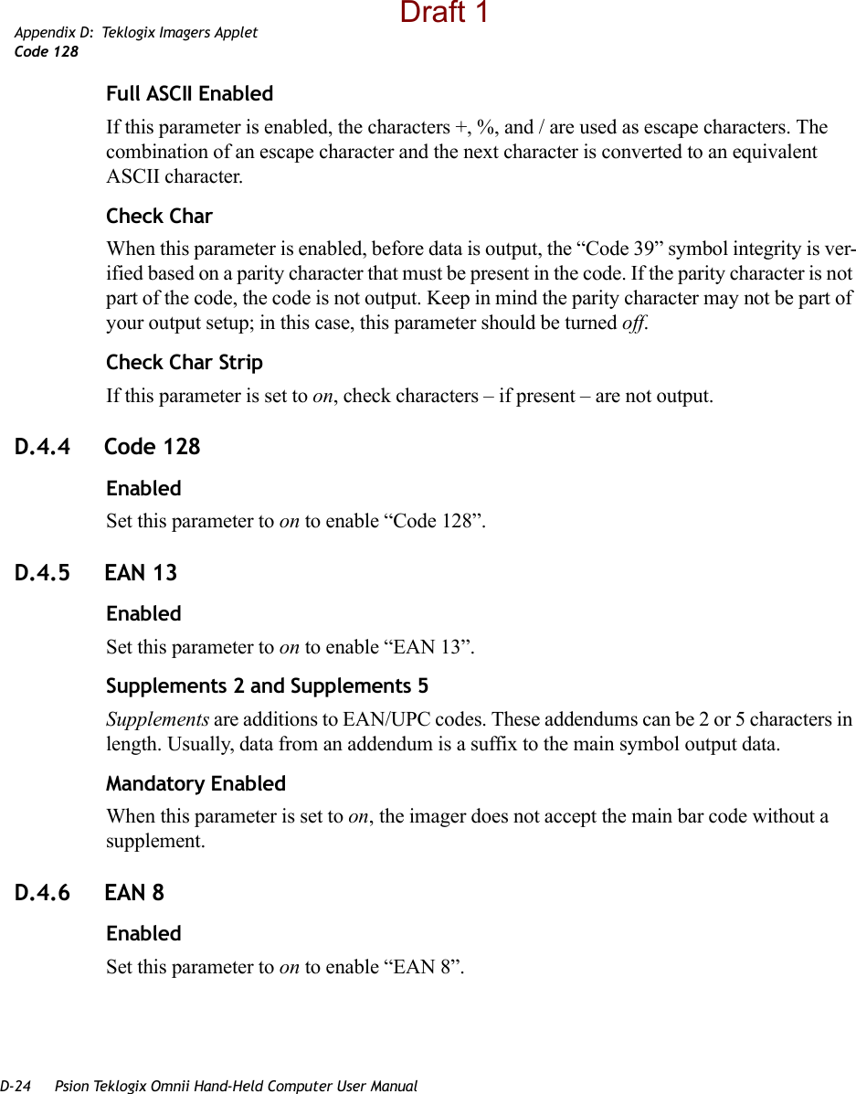
![Appendix D: Teklogix Imagers AppletConfiguring the Image Capture Presets (Imaging Tab)Psion Teklogix Omnii Hand-Held Computer User Manual D-9• Highlight the custom preset, and double-tap on the Edit button.• Tap on the + symbols to expand the lists so that you can view the parameter settings.• Scroll through the parameter list until you reach the parameter that you want to change.• For a parameter that can take a range of values:- Highlight the parameter, and then press the [SPACE] key or double-click on the parameter.- An associated dialog box containing the valid range of values for the parameter and the current setting like the sample screen following is displayed.- Type a value in the field provided.• For a parameter that toggles between two values such as on or off and enabled or disabled:- Highlight the parameter and then press the [SPACE] key, or double-click on the parameter. Either method toggles between the two available values.• When you’ve completed your edits, tap on OK.The parameter list is displayed; the new value for the changed parameter is shown.• Tap on OK to exit to the preset list and save the changes.Draft 1](https://usermanual.wiki/Psion/7545MBWZ.User-Manual-2/User-Guide-1681035-Page-142.png)
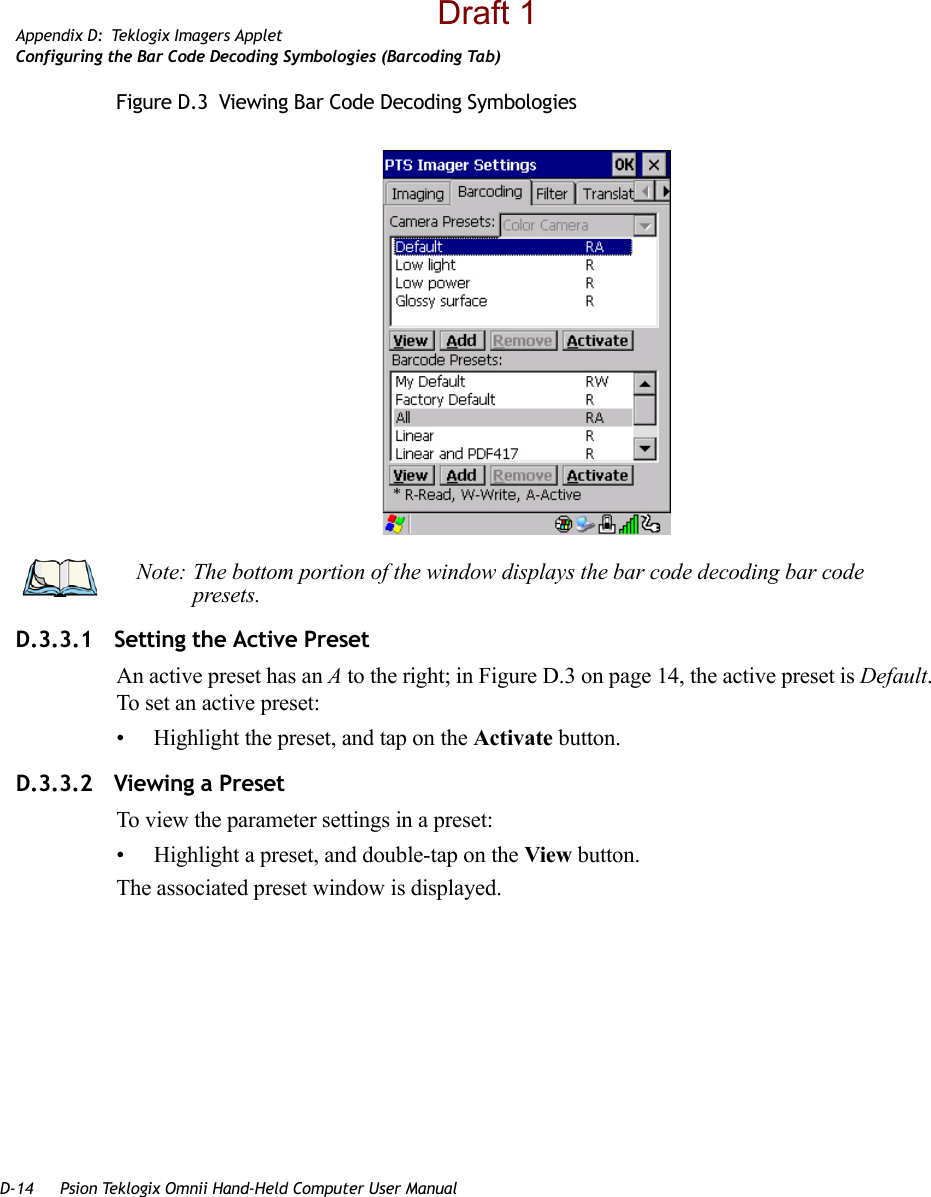
![D-12 Psion Teklogix Omnii Hand-Held Computer User ManualAppendix D: Teklogix Imagers AppletConfiguring the Bar Code Decoding Camera Presets (Barcoding Tab)• Type the name of the new preset in the dialog box.• Tap on OK to save your changes.The preset list is displayed; the new custom preset appears at the end of the list. It is marked as read and write.D.3.2.5 Modifying a Custom PresetThe parameter values in a custom preset can be modified. It is recommended that very few changes be made to a custom preset. To ensure that it will work reliably, it should be as close as possible to the original predefined preset. To change a parameter value:• Highlight the custom preset, and double-tap on the Edit button.• Tap on the + symbols to expand the lists and view the parameter settings.• Scroll through the parameter list until you reach the parameter that you want to change.• For a parameter that can take a range of values:- Highlight the parameter, and then press the [SPACE] key or double-click the parameter.Draft 1](https://usermanual.wiki/Psion/7545MBWZ.User-Manual-2/User-Guide-1681035-Page-145.png)
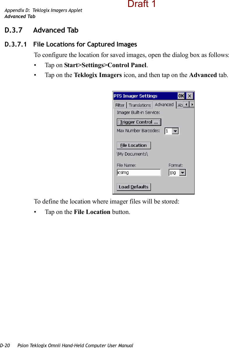
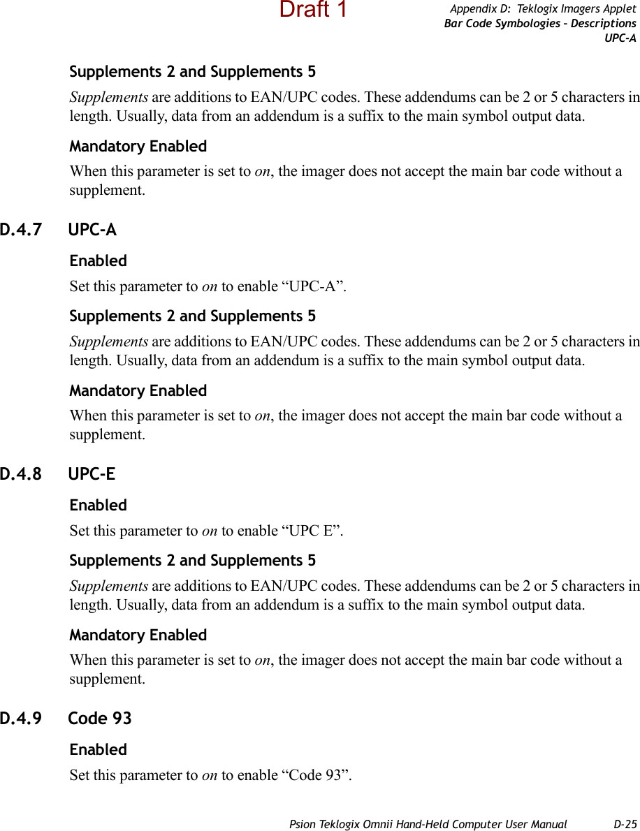
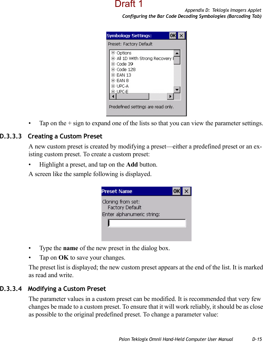
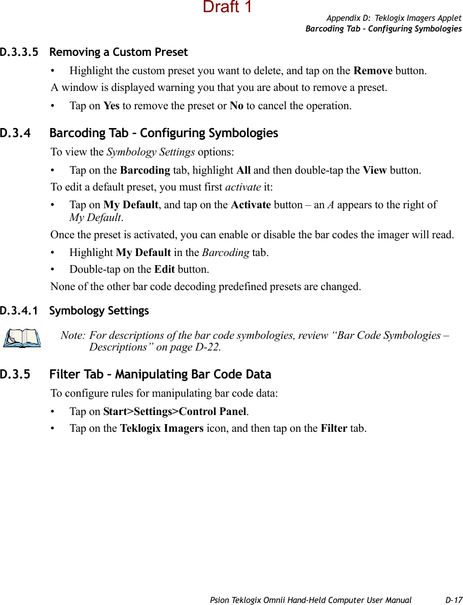
![Appendix D: Teklogix Imagers AppletConfiguring the Bar Code Decoding Symbologies (Barcoding Tab)Psion Teklogix Omnii Hand-Held Computer User Manual D-13- An associated dialog box containing the valid range of values for the parameter and the current setting like the sample screen following is displayed.- Type a value in the field provided.• For a parameter that toggles between two values such as on or off and enabled or disabled:- Highlight the parameter and then press the [SPACE] key, or double-click on the parameter. Either method toggles between the two available values.• When you’ve completed your edits, tap on OK.The parameter list is displayed; the new value for the changed parameter is shown.• Tap on OK to exit to the preset list and save the changes.D.3.2.6 Removing a Custom Preset• Highlight the custom preset you want to delete, and tap on the Remove button.A window is displayed warning you that you are about to remove a preset.• Tap on Ye s to remove the preset or No to cancel the operation.D.3.3 Configuring the Bar Code Decoding Symbologies (Barcoding Tab)To configure the bar code decoding camera presets:• Tap on Start>Settings>Control Panel>Teklogix Imagers.• Tap on the Barcoding tab.Draft 1](https://usermanual.wiki/Psion/7545MBWZ.User-Manual-2/User-Guide-1681035-Page-146.png)
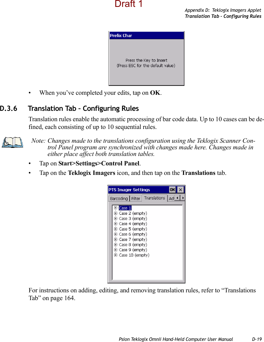
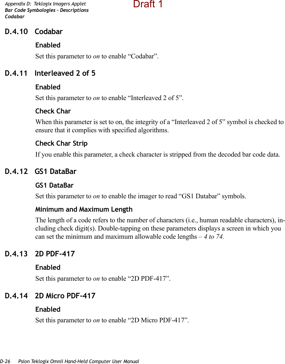
![D-16 Psion Teklogix Omnii Hand-Held Computer User ManualAppendix D: Teklogix Imagers AppletConfiguring the Bar Code Decoding Symbologies (Barcoding Tab)• Highlight the custom preset, and double-tap on the Edit button.• Tap on the + symbols to expand the lists and view the parameter settings.• Scroll through the parameter list until you reach the parameter that you want to change.• For a parameter that can take a range of values:- Highlight the parameter, and then press the [SPACE] key or double-click the parameter.- An associated dialog box containing the valid range of values for the parameter and the current setting like the sample screen following is displayed.- Type a value in the field provided.• For a parameter that toggles between two values such as on or off and enabled or disabled:- Highlight the parameter and then press the [SPACE] key, or double-click on the parameter. Either method toggles between the two available values.• When you’ve completed your edits, tap on OK.The parameter list is displayed; the new value for the changed parameter is shown.• Tap on OK to exit to the preset list and save the changes.Draft 1](https://usermanual.wiki/Psion/7545MBWZ.User-Manual-2/User-Guide-1681035-Page-149.png)
![D-18 Psion Teklogix Omnii Hand-Held Computer User ManualAppendix D: Teklogix Imagers AppletFilter Tab – Manipulating Bar Code DataD.3.5.1 Modifying a Bar Code SettingThe rules for manipulating data from selected bar code symbologies can be modified. To change the settings for a symbology:• Tap on the + symbols to expand the lists and view the parameter settings.• Scroll through the parameter list until you reach the parameter that you want to change.• For a parameter that can take a range of values:- Highlight the parameter, and then press the [SPACE] key or double-click the parameter.- An associated dialog box containing the valid range of values for the parameter and the current setting like the sample screen following is displayed.- Type a value in the field provided.• For a parameter that takes a single character:- Highlight the parameter and then press the [SPACE] key, or double-click the parame-ter. The following screen is displayed:Draft 1](https://usermanual.wiki/Psion/7545MBWZ.User-Manual-2/User-Guide-1681035-Page-151.png)