Psion 7545MBWZ Handheld Computer User Manual Omnii Hand Held Computer
Psion Inc Handheld Computer Omnii Hand Held Computer
Psion >
Contents
- 1. User Manual 1
- 2. User Manual 2
User Manual 2
Chapter 5: Configuration
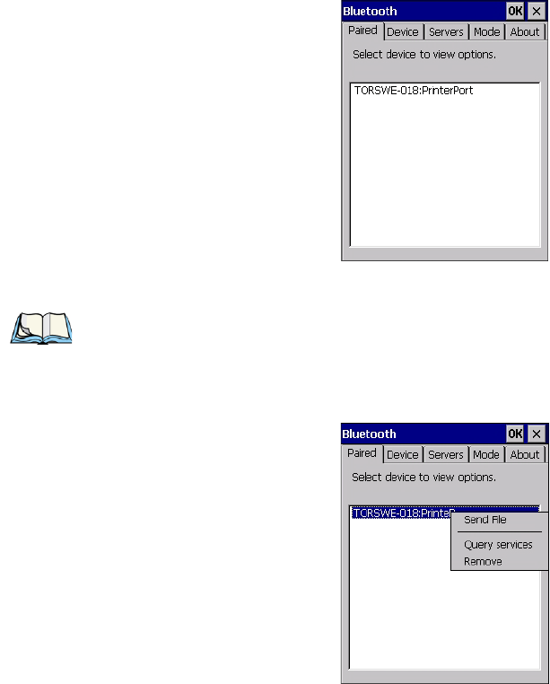
Paired Tab
Psion Teklogix Omnii Hand-Held Computer User Manual 135
To learn how to scan for devices to pair, review “Device Tab” on page 136.
• Tap on an item in the Paired tab to display an associated pop-up menu.
The displayed menu depends on the type of the service chosen.
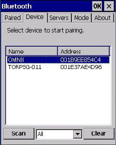
Query Services and Remove Commands
•Query Services displays a Services dialog box where a pairing service is chosen.
•Remove unpairs the highlighted service and deletes the entry from the tab.
Note: If a service is actively paired and connected, the device and its services are displayed
in bold typeface in this list.
Chapter 5: Configuration
Device Tab
136 Psion Teklogix Omnii Hand-Held Computer User Manual
OBEX OPP (Object Exchange-Object Push Profile) Commands
The OPP defines two roles—a Push Server and a Push Client. Push Server is the device that
provides an object exchange server. Push Client is the device that pushes and pulls objects to
and from the Push Server.
OBEX OPP contains the following unique menu option:
•Send File displays an Open File dialog box where the file to be sent can be selected.
When the transmission begins, another dialog box tracks the progress of the file
transmission.
HSP/HFP (Headset Profile/Hands-Free Profile) Service Commands
The HSP (Headset Profile) allows users to connect their device to Bluetooth enabled head-
sets and other audio devices.
HSP/HFP services provide the following unique menu options:
•Connect Audio establishes an audio connection to the Bluetooth headset.
•Disconnect Audio disconnects the audio connection from the Bluetooth headset.
•Volume Control displays a dialog box where the headset and microphone volume can
be adjusted.
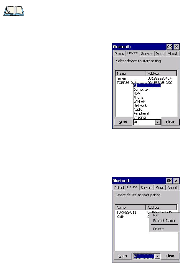
5.6.2 Device Tab
In this tab, users can discover and display Bluetooth devices.
5.6.2.1 Discovering and Removing Devices
Scan discovers Bluetooth devices in range of Omnii and lists them in this tab. Any existing
devices previously discovered and listed will also be displayed.
Chapter 5: Configuration
Device Tab
Psion Teklogix Omnii Hand-Held Computer User Manual 137
Clear removes all Bluetooth devices listed except those with currently paired and connected
services.
5.6.2.2 Filtering By Class of Device (COD)
This menu allows you to filter the displayed devices by their COD. If, for example, you
choose Computer from this menu, only the devices that have the matching Computer COD
value will be displayed. Choosing All lists all detected devices.
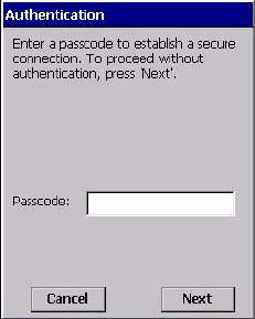
5.6.2.3 Device Pop-up Menu
The Device pop-up menu allows you to pair a device, update a device name or delete a
device from the list.
Note: To limit the number of devices listed to a particular type of device, refer to “Filtering
By Class of Device (COD)”, next section.
Chapter 5: Configuration
Device Tab
138 Psion Teklogix Omnii Hand-Held Computer User Manual
Pair begins the pairing process by inquiring the services and profiles of the discovered
device. An authentication dialog box is displayed the first time a Bluetooth device is paired.
Refresh Name repeats the device name inquiry, updating the name. This command is useful
if a device is listed without a name (unknown), or if a device name has been changed
remotely.
Delete removes this device from the list.
5.6.2.4 Pairing a Device
To pair devices:
• Follow the manufacturer’s instructions to place the remote device in pairing mode.
• Choose the Devices tab and Scan for devices in your area.
• When the scan is complete, tap on the device to which you want to pair.
• In the pop-up Device menu, tap on Pair.
An Authentication dialog box is displayed.
• If the remote device has authentication enabled, type the PIN in this dialog box.
• To proceed without authentication, tap on Next.
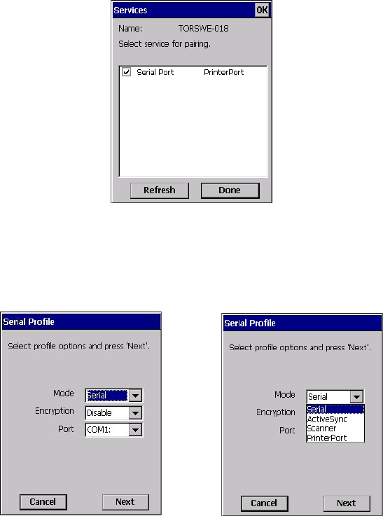
After entering the device PIN, the Services dialog appears with a list of services available for
that device.
Chapter 5: Configuration
Device Tab
Psion Teklogix Omnii Hand-Held Computer User Manual 139
• Click in the checkbox to the left of the service to activate it.
•Click on Done.
Services that require more information present a configuration dialog box. Serial Profile is
an example.
This dialog box offers a number of additional options such as enabling Encryption and se-
lecting four different Modes: Serial, ActiveSync, Scanner, and Printer Port.
Serial is used for simple serial port communication.
ActiveSync is for ActiveSync-over-Bluetooth.
Scanner is used to create a connection to a bar code scanner. A serial connection is created,
then the Scanner Services is notified of the connection so that the incoming bar code scan
will be forwarded to Scanner Services directly.
Chapter 5: Configuration
Servers Tab
140 Psion Teklogix Omnii Hand-Held Computer User Manual
Printer Port must be chosen here if you want to communicate with a paired Bluetooth
printer. For further details, see “Mode Tab” on page 141.
• Once you’ve completed the information, tap on Next and then in the Services screen,
click on Done.
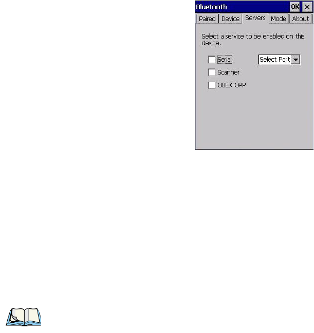
5.6.3 Servers Tab
When a remote Bluetooth device initiates a Bluetooth connection to Omnii, the remote
device is considered the ‘Bluetooth master’ and the hand-held, the ‘Bluetooth slave’. In
order for the remote device to connect to the hand-held, Omnii must offer a service in the
form of a server. The Servers tab allows these services to be enabled and configured. There
are three server services available: Serial, Scanner and OBEX OPP.
Serial server enables the Serial Port Profile server; a Serial Port can be selected from the
drop-down menu.
You can assign either a BSP or a COM prefix from the drop-down menu. BSP (Bluetooth
Serial Port) was created by Microsoft to allow Bluetooth to have its own serial prefix in
order to free up virtual COM prefixes as these are limited and are widely used.
Scanner server enables a Serial Port Profile server and then relays it to the Scanner Service
(SCS). This is used for Bluetooth bar code scanners that operate in client mode. SCS opens
the server port and handles the scanner input.
Note: Even after a Serial Port Profile server is created, an application must open the cre-
ated port before a remote device can connect.
Chapter 5: Configuration
Mode Tab
Psion Teklogix Omnii Hand-Held Computer User Manual 141
OBEX OPP server enables the Object Push Profile server. A warm reset must be performed
on Omnii after a change is made to this option. The OPP Server allows other Bluetooth
devices to send files to this device.
• Tap on the checkbox to activate the server.
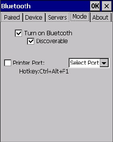
5.6.4 Mode Tab
Turn on Bluetooth activates the Bluetooth radio.
Discoverable determines whether Omnii is visible or invisible to other devices.
Printer Port allows you to assign and enable a virtual outgoing COM port selected from the
drop-down menu to communicate with a paired Bluetooth printer. Keep in mind that when a
port is chosen, the printer must be on and connected to the chosen port for a remote device to
be able to connect.
• Select a port within the Printer Port drop-down list, e.g. BSP1:
• Check the Printer Port check box.
•Open the Device tab and tap on Scan.
• Tap-and-hold each Bluetooth Printer device entry and then select Pair, key-in the Pass-
code (if needed) and then tap Done. DO NOT select any services!
•Close the Bluetooth Manager.
• Select the Bluetooth device to print to—you will need to key-in (or programmatically
raise) the following key sequence [CTRL] [ALT] [F1].
• You can now select the Bluetooth device to which you wish to print.
Chapter 5: Configuration
About Tab
142 Psion Teklogix Omnii Hand-Held Computer User Manual
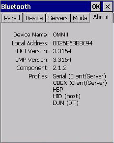
5.6.5 About Tab
Device Name displays the broadcasted name of the hand-held. The name can be changed in
the System Properties applet: Start>Settings>Control Panel>System
icon>Device Name tab.
Local Address displays the MAC address (BD_Addr) of the Bluetooth chip.
HCI Version & LMP Version display the version of the chip firmware.
Component indicates the version of the Psion Teklogix Bluetooth Subsystem (the manager,
drivers, etc).
Profiles lists the supported profiles on this specific Omnii.
5.6.6 The Bluetooth GPRS WAN Connection
The following steps describe how to set up an Internet data connection using a GSM cellular
telephone with Bluetooth. Omnii communicates via Bluetooth to the cell phone, which then
accesses a WAN (Wide Area Network) and transfers data using GPRS.
1. Enable the Dial-Up Networking service in the cell phone.
2. Make the phone discoverable.
3. Pair the phone service with the Omnii Dial-Up Networking service using the
Bluetooth Manager. (For instructions on pairing devices, refer to “Pairing a
Device” on page 138.)
Chapter 5: Configuration
The Bluetooth GPRS WAN Connection
Psion Teklogix Omnii Hand-Held Computer User Manual 143
4. To set up the Internet parameters, choose the Network And Dial-up Connections
icon from the Control Panel.
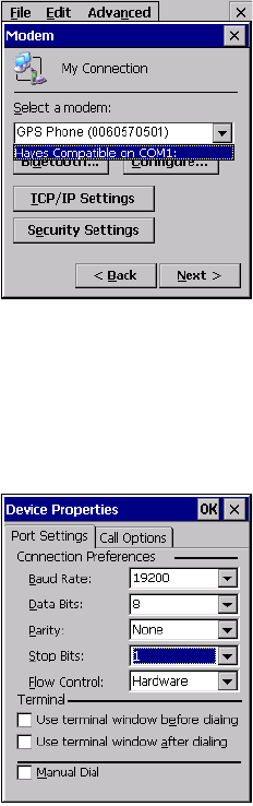
5. Tap on Make New Connection.
6. In the Make New Connection dialog box, choose Dial-Up Connection. Enter a
name for your GPRS network connection.
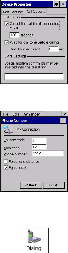
7. Choose the Next button to display the Modem dialog box.
Chapter 5: Configuration
The Bluetooth GPRS WAN Connection
144 Psion Teklogix Omnii Hand-Held Computer User Manual
8. In the drop-down menu labelled Select a modem, choose the name of the modem
with which you want to connect, and then choose the Configure button to display
the Device Properties dialog box.
Omnii communicates via Bluetooth to your Bluetooth equipped cellular telephone and re-
trieves the parameters for the Device Properties dialog box. Omnii then disconnects.
9. Under the Call Options tab, turn off Cancel the call if not connected within, and
press [ENTER] to save your changes.
Psion Teklogix Omnii Hand-Held Computer User Manual 145
Chapter 5: Configuration
The Bluetooth GPRS WAN Connection
Pairing a Device
10. In the Modem dialog box, choose the Next button to display the Phone Number
dialog box.
The phone number you enter is network carrier dependent. Once you’ve specified all the
necessary information, choose the Finish button.
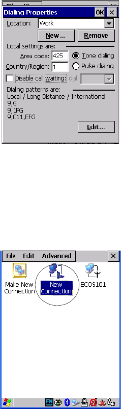
11. In the Control Panel, choose the Dialing icon.
12. The values in the Dialing Properties dialog box need to be edited according to your
network carrier specifications.
Chapter 5: Configuration
The Bluetooth GPRS WAN Connection
146 Psion Teklogix Omnii Hand-Held Computer User Manual
Once you’ve edited this dialog box to reflect your network carrier requirements, press
[ENTER] to save your changes.
13. At this point, return to the Control Panel, and choose the Network and Dial-up
Connections icon.
14. In the network connection window, the new network configuration—in this case,
New Connection is displayed. Tap on the new icon.
When you tap on your new connection, an onscreen message indicates the status of your
connection: connected, disconnected, error messages, and so on.
Chapter 5: Configuration
Dr. Debug
Psion Teklogix Omnii Hand-Held Computer User Manual 147
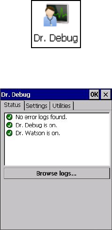
5.7 Dr. Debug
Dr. Debug is an error diagnostic and troubleshooting tool.
• Tap on Start>Settings>Control Panel. Tap on the Dr. Debug icon.
5.7.1 Status
This tab indicates the status (on/off) of the debug engines. Tapping on Browse logs displays
error logs for your review. The logs should be used as reference when working with Psion
Teklogix Technical Support personnel.
Chapter 5: Configuration
Settings
148 Psion Teklogix Omnii Hand-Held Computer User Manual
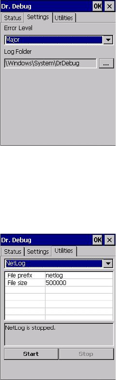
5.7.2 Settings
• Choose an Error Level from the drop-down menu.
• To change the location where debug information will be stored, tap on the button to the
right of the Log Folder option.
5.7.3 Utilities
The Utilities tab is used to log network traffic. When you tap on the Start button, debug data
is collected so that, if necessary, it can be forwarded to a Psion Teklogix technician for
evaluation.
Chapter 5: Configuration
Error Reporting
Psion Teklogix Omnii Hand-Held Computer User Manual 149
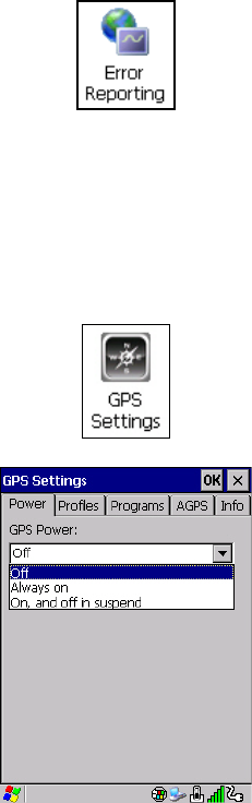
5.8 Error Reporting
Error Reporting allows you to enable or disable Microsoft error reporting prompts.
• Tap on Start>Settings>Control Panel>Error Reporting icon to access your options.
5.9 GPS (Global Positioning System) Settings
This applet allows you to define how the GPS module operates. You can determine when the
GPS module is powered and operating, and choose from a set of GPS profiles built into the
modem. You can also set up AGPS (Assisted Global Positioning System).
• Tap on Start>Settings>Control Panel>GPS Settings icon.
5.9.1 Power
This tab allows you to dictate how the GPS module behaves. The GPS Power drop-down
menu is used to control when the GPS is powered on and off.
•Off – the GPS module is left off, always.
Chapter 5: Configuration
Profiles
150 Psion Teklogix Omnii Hand-Held Computer User Manual
• Always on – the GPS module is powered on at all times regardless of the power state of
the hand-held (suspend or standby).
•On, and off in suspend – the GPS module is powered on, but if Omnii is in suspend
mode, the GPS module is turned off.
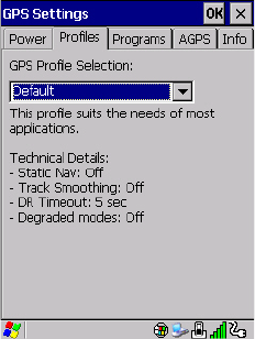
5.9.2 Profiles
Tapping on the GPS Profile Selection drop-down menu allows you to choose an appropriate
profile: Default, Automotive or Pedestrian.
•Default profile is a good general profile suitable for most uses.
•Automotive profile is designed for in-vehicle use, providing quick location updates as
the vehicle moves. When the GPS module is set to this profile and the vehicle enters an
area such as a tunnel where satellite coverage is interrupted, it will attempt to predict the
vehicle position.
•Pedestrian profile is designed for those using the GPS module while walking. It takes
into account the slower pace of the pedestrian when mapping the location of the user.
When the GPS module is set to this profile and the operator moves into an area where
satellite coverage is interrupted, the GPS module will not attempt to predict the opera-
tor’s movement.
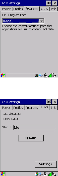
5.9.3 Programs
Tap on the GPS Program Port drop-down menu to choose the communication (COM)
port that the GPS software will use to communicate with the GPS receiver.
Chapter 5: Configuration
AGPS (Assisted Global Positioning System)
Psion Teklogix Omnii Hand-Held Computer User Manual 151
5.9.4 AGPS (Assisted Global Positioning System)
To determine your location, a GPS module receives data from three or more GPS satellites
in fixed orbit around the Earth. The GPS module triangulates your location based on the
time it takes for signals to get to and from the satellites. This works well in fairly clear areas,
outdoors for example. However, if you’re attempting to triangulate your location in city
centres where signals bounce off tall concrete buildings or from within a building, the GPS
module will have greater difficulty calculating a fix.
AGPS reduces Time To First Fix (TTFF) and increases the likelihood of finding and keeping
a fix in poor coverage areas such as indoor sites. AGPS downloads satellite ephemeris (or-
bital) data to Omnii periodically through Wi-Fi or WWAN. The downloaded data is used by
the GPS module to speed the process of getting a fix.
Chapter 5: Configuration
AGPS (Assisted Global Positioning System)
152 Psion Teklogix Omnii Hand-Held Computer User Manual
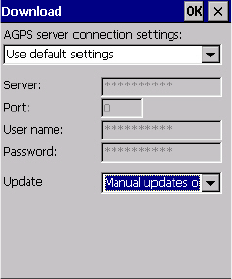
Update
•Click on the Update button to download Extended Ephemeris (EE) files from a secure
host on the Internet using any interface that has an Internet connection. These files
contain several days worth of ephemeris (orbital) data that can be used if the satellite’s
broadcast ephemeris is not available.
The Status field above the Update button displays the progress of the download, and once
successfully downloaded, the Status field will read Idle.
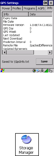
Settings
•Click on the Settings button to define the AGPS server connection settings.
The AGPS server connection settings drop-down menu allows you to choose from two set-
tings: Use default settings and Use custom settings.
The Use default settings option is generally acceptable for most applications. Note that aside
from the Update field in which you can choose how long the fix is stored in your Omnii, the
field values cannot be edited.
The Use custom settings option is generally used to configure devices that will have access
only to an intranet rather than the Internet and should only be altered with the assistance of
qualified Psion Teklogix personnel. They will be able to help you configure your Psion Tek-
logix devices and web server to retrieve the ephemeris data.
Chapter 5: Configuration
Info
Psion Teklogix Omnii Hand-Held Computer User Manual 153
5.9.5 Info
This tab provides general information about the GPS module such as the firmware version,
the date on which files were last updated, and so on. If GPS module support service is re-
quired, you may be asked to tap on the Save button in this tab and forward the information
to Psion Teklogix support staff.
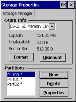
5.10 Storage Manager
The Storage Manager allows you to view information about the storage devices that are
present in Omnii, such as SD-MMC flash cards and Compact Flash cards.
5.10.1 Formatting a Memory Card
Formatting a memory card bulk-erases it. Once a card is erased, partitions may be created in
it, similarly to those on a hard drive. Memory-card devices are normally ‘mounted’ (made
available to the system) automatically when they are inserted. They must be dismounted
before they can be formatted.
To format an entire memory card:
1. Select Start> Settings>Control Panel.
Chapter 5: Configuration
Creating Partitions
154 Psion Teklogix Omnii Hand-Held Computer User Manual
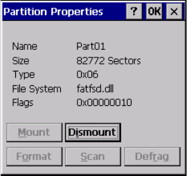
2. In Control Panel, double-click on the Storage Manager icon. The Storage Manager
menu opens:
3. Select the memory card from the drop-down list.
4. Press the Dismount button to dismount the memory card. All partitions on the card
will be dismounted.
5. Press the Format button to format the memory card.
All partitions and information on the card will be erased during the formatting process.
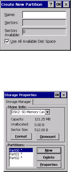
5.10.2 Creating Partitions
Once the card is formatted, new partitions can be created in it. The default is to create one
partition that occupies the whole card, but a card can be divided into more than one partition
if desired. Each partition appears as a separate folder in Windows Explorer.
To create new partitions:
1. Press the New button next to the Partitions list box. The Create New Partition dialog
box appears:
Chapter 5: Configuration
Partition Management
Psion Teklogix Omnii Hand-Held Computer User Manual 155
2. Type a name for the partition.
3. If more than one partition is desired, uncheck the Use All Available Diskspace
checkbox, then specify the desired number of sectors to be used by the partition.
4. Press OK. The new partition appears in the Partitions list.
The new partition is automatically mounted. This is indicated by an asterisk (*) next to its
name in the partition list. Any unallocated space on the card is indicated at the left, and addi-
tional partitions can be created in it.
5.10.3 Partition Management
Partitions can be individually dismounted, mounted, deleted, or formatted as well. These
and additional tasks are available from the Partition Properties dialog:
Chapter 5: Configuration
Partition Management
156 Psion Teklogix Omnii Hand-Held Computer User Manual
To dismount a partition:
1. Choose the desired partition.
2. Tap the Properties button. The Partition Properties dialog appears.
3. Tap the Dismount button. The partition is dismounted. The asterisk disappears next
to its name in the partitions list.
To delete a partition:
1. Select the desired partition.
2. Tap the Delete button. A warning dialog appears.
3. Tap the OK button. The partition is deleted.
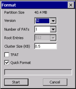
To format a partition:
1. Choose the desired partition.
2. Tap the Properties button. The Partition Properties dialog appears.
3. Tap the Dismount button. The partition is dismounted. The asterisk disappears next
to its name in the partitions list.
4. Tap the Format button. The Format dialog appears:
Chapter 5: Configuration
Partition Management
Psion Teklogix Omnii Hand-Held Computer User Manual 157
5. Choose your format options. These options include:
• Version of file system (FAT-16, for devices holding up to 4 GB; or FAT-32, for
devices containing up to 32 GB).
• Number of FATs (File-Allocation Tables).
• Number of entries allowed in the root directory.
• Cluster size (.5 KB to 64 KB).
There are also two checkboxes, which govern:
• Whether to use the transaction-safe FAT file system (TFAT). This file system keeps
multiple copies of the file-allocation table, changing one while maintaining another
as a backup.
• Whether to perform a quick format. Quick formatting removes all reference to data in
the partition without erasing the actual partition. The partition will be treated as
empty, and new data will overwrite it.
6. Tap Start. The partition is formatted.
To mount a partition:
1. Choose the desired partition.
2. Tap the Properties button. The Partition Properties dialog appears.
3. Tap the Mount button. The partition is mounted. The asterisk appears next to its
name in the partitions list.
The Partition Properties dialog has buttons for additional functions. Partitions can be defrag-
mented, and their file structure can be scanned.
Chapter 5: Configuration
Tek log ix Im a g er s
158 Psion Teklogix Omnii Hand-Held Computer User Manual
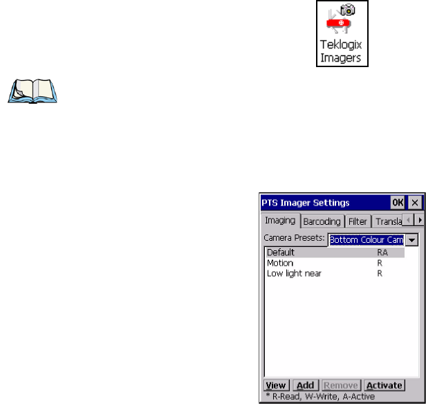
5.11 Teklogix Imagers
The Teklogix Imagers applet is used to create, modify, delete, and activate imager settings.
The principle uses of the applet are to decode bar codes and to capture images. A Demon-
stration Application is provided to demonstrate how the imager works. Refer to “Demo” on
page 71 for details.
Refer to Appendix D: “Teklogix Imagers Applet” for configuration details.
To launch this applet:
•In the Control Panel, choose the Teklogix Imagers icon.
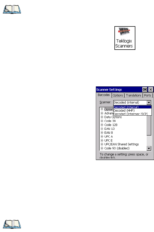
5.12 Teklogix Scanners
The Teklogix Scanners icon in the Control Panel provides dialog boxes in which you can
tailor bar code scanner configuration and choose the bar codes your scanner will recognize.
Note: This icon is only displayed when the appropriate imager is installed in your Omnii.
If there is an imager installed but this icon is not present, additional software (ICS)
may need to be installed.
To enable a newly-installed imager, Press and hold down the [FN] key and the
[ENTER/Power] key simultaneously for a minimum of three seconds.
Chapter 5: Configuration
Bar Codes Tab
Psion Teklogix Omnii Hand-Held Computer User Manual 159
The parameters are preset with the default settings of the decoded scanner installed in
the unit.
For a listing of available scanners and their specifications, please refer to Chapter 7:
“Specifications”.
5.12.1 Bar Codes Tab
5.12.1.1 Scanner
The drop-down menu to the right of the Scanner option allows you to choose configurations
for one of the following scanner types, depending on what is installed in/on your hand-held:
Decoded (internal), Decoded (Intermec ISCP), Imager and Non-decoded.
The symbologies listed in the Barcodes tab change to reflect the scanner you choose and the
bar codes it supports. Always defer to your bar code scanner’s programming manual when
in doubt about the availability or settings for any parameter.
Note: To enable a newly-installed scanner, press and hold down the [FN] key and the
[ENTER/Power] key simultaneously for a minimum of three seconds.
Note: Your Omnii comes preconfigured from the factory for internal scanner types. The
type of scanner installed can be determined from the System icon in the Control
Panel, under the System Properties tab.
Chapter 5: Configuration
Bar Codes Tab
160 Psion Teklogix Omnii Hand-Held Computer User Manual
Keep in mind that some bar code types are only available when an internal imaging scanner
is installed. All internal scanners can be configured using these dialog boxes.
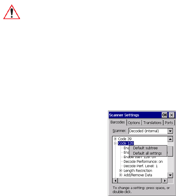
5.12.1.2 Restoring Default Settings
If you want to restore the factory defaults after making changes, the defaults can be applied
to a selected parameter, sub-tree of parameters or all scanner parameters.
• Press and hold on a symbology (e.g., Code 128) to display a pop-up menu.
• Choose Default subtree to reset only the parameters in the symbology you selected, or
choose Default all settings to reset all scanner parameters to default settings.
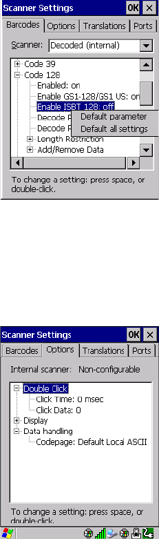
To reset a single parameter to its default setting:
• Press and hold on the parameter you want to reset.
Important: To improve the decode speed and performance, enable (set to ‘on’) only
those codes that are required by the application.
For information on configuring the bar code symbologies, see Appendix C:
“Bar Code Settings - TBD”.
Chapter 5: Configuration
Options Tab
Psion Teklogix Omnii Hand-Held Computer User Manual 161
• Choose Default parameter to reset the parameter to the default setting.
5.12.2 Options Tab
This tab allows you to tailor the double-click parameters, display, and data handling options
associated with your scanner.
5.12.2.1 Double Click Parameters
Click Time (msec)
This parameter controls the maximum gap time (in milliseconds) for a double-click. If the
time between the first and second clicks of the scanner trigger is within this time, it is con-
sidered a double-click. The allowable range is 0 to 1000. A value of zero disables this
feature.

Chapter 5: Configuration
Options Tab
162 Psion Teklogix Omnii Hand-Held Computer User Manual
A double-click produces different results depending on whether or not a value is assigned in
the “Click Data” parameter. When a value is not assigned for the “Click Data”, double-click-
ing the scanner trigger overrides the target dot delay set in the “Dot Time” parameter and
initiates a normal scan sweep. If a value is assigned for the “Click Data” parameter, double-
clicking the scanner trigger inserts the “Click Data” value rather than initiating a scan.
Click Data
This parameter determines which character is sent to the application installed in your Omnii
following a double-click. A dialog box appears, asking that you press the key you want to
insert. The ASCII/Unicode key value of the keypress is displayed.
Pressing the [ESC] key in this dialog box resets the data to zero.
5.12.2.2 Display Parameters
Scan Result
When this parameter is enabled, the type of bar code and the result of the scan appear on the
screen. Note that this information is only displayed after a successful decode and is visible
only while the scanner trigger is pressed. When the trigger is released, this information is
cleared from the screen.
Scan Indicator
When this parameter is enabled, the laser warning logo appears on the display whenever the
scanner is activated.
Scan Result Time (sec)
The value assigned to the Scan Result Time parameter determines how long the scan results
of a successful scan are displayed on the screen. Time is measured in seconds, and a value of
0 (zero) disables the parameter. When you choose this option, a dialog box appears where
you can enter a value.
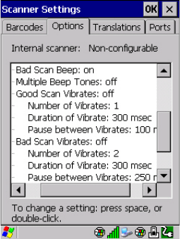
Good Scan Beep and Bad Scan Beep
These parameters determine whether or not Omnii emits an audible scanner ‘beep’ when a
good (successful) scan or a bad (unsuccessful) scan is performed. Set these parameters to
either on to enable the beeper or off to disable it.
Note: To remove the scan result from the screen before the “Result Time” has expired,
point the scanner away from the bar code and press the trigger.
Chapter 5: Configuration
Options Tab
Psion Teklogix Omnii Hand-Held Computer User Manual 163
Multiple Beep Tones
You can set the audible scanner ‘beep’ to emit a series of three beeps instead of one. Set this
parameter to on to enable the multiple beep tones.
Good Scan Vibrates and Bad Scan Vibrates
These parameters determine whether or not Omnii creates a vibration when a good (success-
ful) scan or a bad (unsuccessful) scan is performed. Set these parameters to on to enable the
vibration. You can set the Number and Duration of vibrations, as well as the Pause between
vibrations. The screen above shows the default settings.
Soft Scan Timeout
This parameter is used by the SDK “Scan” function (soft-scan: starting a scan session via the
SDK function, instead of a physical user trigger press). The value assigned to this parameter
determines the soft-scan timeout from 1 to 10 sec (default is 3 sec).
Scan Log File
If this parameter is enabled, the input bar code and the modified/translated output bar code
are logged in the file \Flash Disk\ScanLog.txt. Keep in mind that if Scan Log File is enabled,
there is a slight performance reduction when performing multiple scans since the log file is
written to persistent storage.
Chapter 5: Configuration
Translations Tab
164 Psion Teklogix Omnii Hand-Held Computer User Manual
5.12.2.3 Data Handling
Codepage
If you are encountering a scan failure because there is an unrecognized language character in
the bar code, the Codepage option may correct the problem by allowing the ISO-8859-1
Latin 1 codepage to be used. The default value is Default Local ASCII.
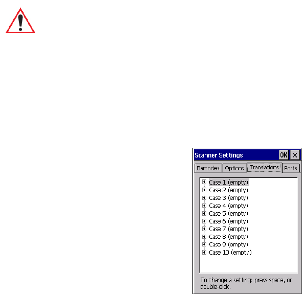
5.12.3 Translations Tab
The Translations menu allows you to define up to 10 cases, each consisting of up to 10 rules
in sequential order. Only one case will be applied to a bar code and a case will only be
applied if all rules specified in the case are successful—if a rule within a case fails, the entire
case fails.
•In the Translation menu, tap on the Case # to create rules.
Important: Do not change this parameter from the default setting unless you are
certain that it will correct your scan problem.
Chapter 5: Configuration
Tr a n s l a t i o n s Ta b
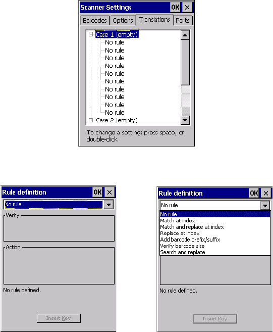
Psion Teklogix Omnii Hand-Held Computer User Manual 165
• Tap on the No rule drop-down menu to display the rules.
When you choose a rule, an associated screen is displayed in which you can define the rule.
Chapter 5: Configuration
Translations Tab
166 Psion Teklogix Omnii Hand-Held Computer User Manual
5.12.3.1 Case Rules
The case rules are defined as follows:
•No rule—ignored.
•Search and replace—replaces all instances of the match string. (Note that this rule
cannot fail.)
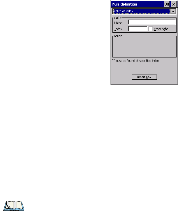
•Match at index—matches the match string at a specified index.
•Match and replace at index—matches the match string at a specified index and
replaces/changes it.
•Replace at index—replaces/changes unspecified data in a given range.
•Add barcode prefix/suffix—adds a global prefix or suffix.
•Verify barcode size—verifies the bar code size. This rule should generally be assigned
first, before creating subsequent rules.
Translation information about the status of each case/rule is displayed in the scan log file
(see “Scan Log File” on page 163) when enabled. This is useful if a case fails, and you are
trying to determine why a rule is failing.
Note: Keep in mind that the effects of previously applied rules must be taken into account
when creating subsequent rules. For example, if the bar code size is important, it
should be checked before any rules that might change the size are applied.
Chapter 5: Configuration
Ports Tab
Psion Teklogix Omnii Hand-Held Computer User Manual 167
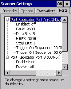
5.12.4 Ports Tab
Figure 5.5 Console and Port Replicator Port Settings
While you cannot configure the scanner, you can configure communications with a serial
decoded scanner using the options in this tab.
Use these settings to ensure that the communication ports on Omnii match the settings of the
serial devices to which they are connected. If the settings do not match exactly, the devices
may not function. Note that some devices can auto-detect serial port settings (such as baud
rate), and in this case Omnii will dictate the settings. Baud rates often have a direct impact
on performance—they should be set as high as possible while still ensuring reliable
communication.
5.12.4.1 Port Replicator Port A (COM5) and Port B (COM6)
Port Replicator Port A (COM5) and Port B (COM6) are standard RS-232 DE-9 DTE ports
on the Omnii port replicator module, available on some snap modules and cradle types.
Enabled
This parameter must be set to ON in order for Omnii to recognize the device connected to
the Port Replicator 9-pin (COM5).
Power (COM6 only) - TBD
Pin 9 on Omnii COM6 is reserved for 5V power out and is defaulted to OFF. This parameter
must be set to ON to enable power to a Snap Module or Vehicle cradle.
Chapter 5: Configuration
Ports Tab
168 Psion Teklogix Omnii Hand-Held Computer User Manual
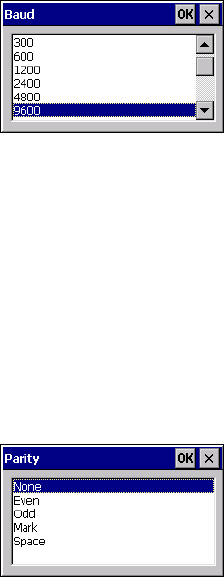
Baud
Double-tapping on this parameter displays a pop-up window in which you can choose an ap-
propriate rate of data transfer.
Figure 5.6 Port Baud Rates
Data Bits
This parameter determines the number of data bits included in each asynchronous data byte.
Most devices use 8-bit data bytes. Double-tapping on this option displays a pop-up window
in which you can choose either 7 or 8 data bits.
Parity
This parameter determines the type of parity checking used on the data going through the
port replicator port. Double-tapping on this option displays a pop-up window in which you
can choose the appropriate parity.
Stop Bits
This parameter specifies the number of stop bits—1, 1.5 or 2—used for asynchronous
communication.
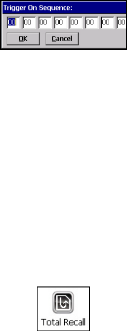
Trigg er On Sequence And Trigger Of f Se quence
If a SICK scanner connected to an Omnii port requires a serial stream of data bytes to trigger
the scanner on and another to trigger the scanner off, the Trigger On Sequence and Trigger
Off Sequence parameters allow you to define these serial streams.
Chapter 5: Configuration
Total Recall
Psion Teklogix Omnii Hand-Held Computer User Manual 169
Double-tapping on Trigger On Sequence or Trigger Off Sequence displays a screen with a
hex array of 10 elements.
These parameters work in conjunction with Manage Triggers sending on and off data
streams to the trigger module you assigned. For example, suppose you launch Manage Trig-
gers and choose Decoded Scanner as the ‘module to trigger’. Next, you assign a ‘trigger
key’—for this example, . (period). To define the serial stream of data bytes to control the on
and off function of the ‘trigger key’, enter a hex value in the Trigger On Sequence and the
Trigger Off Sequence fields. When you press the trigger key, the Trigger On Sequence is
sent and when you release the trigger key, the Trigger Off Sequence is sent, turning the
trigger key on and off.
5.13 Total Recall
Total Recall is a Psion Teklogix utility developed to maintain applications and settings
during a cold boot, and clone settings to other devices. This utility is based on a backup and
restore concept.
•In the Control Panel, choose the Total Recall icon.
Chapter 5: Configuration
Creating a Backup Profile
170 Psion Teklogix Omnii Hand-Held Computer User Manual
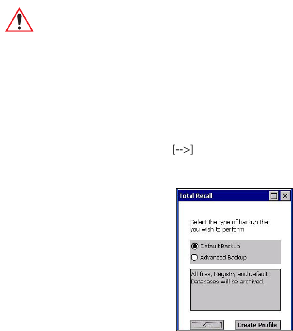
5.13.1 Creating a Backup Profile
In the start up screen, you can choose from four options: Create Profile, Restore Profile,
View Profile and Delete Profile.
• Tap on the Create Profile button to begin the process.
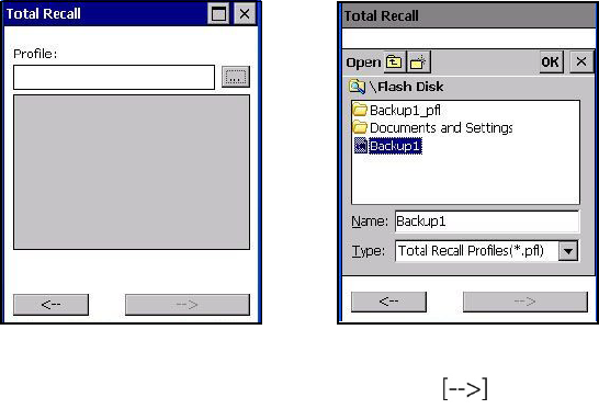
Profile Information
This dialog box displays the default profile name, the type of restore – AutoRestore or Man-
ualRestore, and the possible storage destination for the profile file.
• To change the Profile Name (optional), tap on the [...] button to the right of the Profile
Location field.
•In the Name field, type a new name. (You may need to move the onscreen keyboard
down to make the Name field visible.)
• Tap on OK to save the new profile name.
Chapter 5: Configuration
Creating a Backup Profile
Psion Teklogix Omnii Hand-Held Computer User Manual 171
• Next, choose the profile Type you want to create:
-ManualRestore – creates a backup that is manually restored by the operator.
-AutoRestore – creates a profile that automatically restores itself following a cold reset
or a clean reset.
• Finally, if you want to choose another location for your backup file (optional), tap on the
[...] button to the right of the Profile Location field.
• Navigate to the new location, and tap on OK to save it.
• Tap on the (Next) button.
Defining the Type of Backup
Default Backup
Default Backup is selected so that all installed or copied files, database entries, and the Reg-
istry are saved. Choose Advanced Backup if you want to tailor your backup.
Important: Any profile not stored in persistent memory (flash disk, external usb drive)
will be erased during a clean boot, therefore you should store profiles on a
persistent drive.
When performing an autorestore, the program only searches for profiles
located in the root folder of persistent drives. If you store your profile any-
where else it will not be restored.
When there are multiple autorestore profiles found, only the latest is
restored.
Chapter 5: Configuration
Creating a Backup Profile
172 Psion Teklogix Omnii Hand-Held Computer User Manual
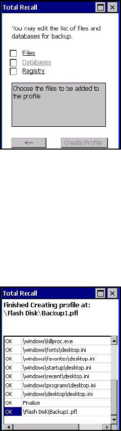
Advanced Backup
Choosing Advanced Backup allows you to define what you would like to include in your
backup profile.
• Tap in the checkbox next to the option(s) listed here to tailor what you want included in
the backup.
Creating a Profile
Once you’ve defined the type of profile you want to create:
• Tap on the Create Profile button.
The options you chose to back up appear in your window as the backup progresses. When
the backup is complete, the last item in the list indicates the location and name of the backup
profile.
Chapter 5: Configuration
Restoring a Profile
Psion Teklogix Omnii Hand-Held Computer User Manual 173
5.13.2 Restoring a Profile
To manually restore a profile:
•In the Total Recall home screen, tap on Restore Profile.
• Tap on the [...] button to the right of the Profile field and locate your backup file.
• Tap on OK.
•In the Profile restore screen, click on the (Next) button.
•Click on Restore Profile to restore the files to your Omnii.
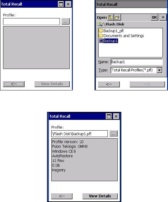
5.13.3 Viewing a Profile
To view a profile:
•In the Total Recall home screen, tap on View Profile.
• Tap on the [...] button to the right of the Profile field, and locate your backup file.
Chapter 5: Configuration
Deleting a Profile
174 Psion Teklogix Omnii Hand-Held Computer User Manual
• Tap on OK.
• Tap on View Details to review your backup files.
5.13.4 Deleting a Profile
•In the Total Recall home screen, tap on Delete Profile.
• In the next screen, locate your backup file, and tap on OK.
A warning pop-up screen appears asking if you’re certain that you want to delete this file.
• Tap on Ye s to delete the file.
Chapter 5: Configuration
TweakIT Settings
175 Psion Teklogix Omnii Hand-Held Computer User Manual
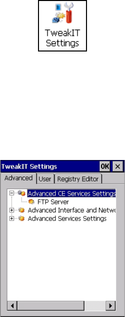
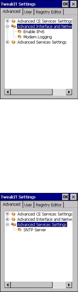
5.14 TweakIT Settings
This utility allows you to ‘tweak’ or adjust Advanced system settings (interface, network,
servers, driver, and radio), User settings (Internet Explorer settings, font size, and docking
port message), and provides a Registry Editor.
5.14.1 Advanced
5.14.1.1 Advanced CE Services Settings
FTP Server
This option is enabled by default to allow file transfers. Keep in mind that data transfer in
either direction is restricted to the Temp folder—that is, data are always loaded from the
FTP Server to the Te mp folder and from the Temp folder to the FTP Server.
If this option is disabled, a warm reset must be performed to accept the change.
Chapter 5: Configuration
Advanced
176 Psion Teklogix Omnii Hand-Held Computer User Manual
5.14.1.2 Advanced Interface and Network Settings
Enable IPv6
This option allows you to enabled Internet Protocol specification, version 6, that has been
published to enable 128-bit IP addresses (replacing version 4).
Modem Logging
When this option is enabled, Omnii logs AT commands (e.g., dial-out information, pass-
word string, etc.) that the administrator can monitor for debugging purposes. Modem
commands are stored in: \MdmLog.txt.
5.14.1.3 Advanced Services Settings
Chapter 5: Configuration
User
177 Psion Teklogix Omnii Hand-Held Computer User Manual
SNTP (Simple Network Time Protocol) Server
The SNTP Server Name typed in this dialog box is used to synchronize Omnii time with the
server time. A warm reset must be performed once the server name as been entered.
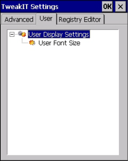
5.14.2 User
5.14.2.1 User Display Settings
User Font Size
This option allows you to adjust the size of the font used in the Omnii display: Large,
Normal, or Small.
Chapter 5: Configuration
Registry Editor
178 Psion Teklogix Omnii Hand-Held Computer User Manual
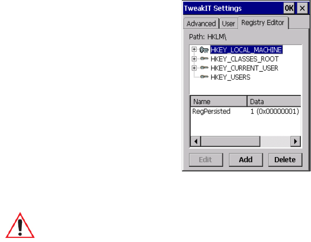
5.14.3 Registry Editor
This option is reserved for senior administrators who have a strong understanding of registry
keys and values.
Warning: Careless registry editing can cause irreversible damage to Omnii.

Chapter 7: Specifications
The Omnii Hand-Held Computer (Model 7545)
Psion Teklogix Omnii Hand-Held Computer User Manual 211
7.1 The Omnii Hand-Held Computer (Model 7545)
7.1.1 Hardware
Physical Dimensions
• Overall: 100 mm width x 42 mm depth x 230 mm length (3.9 in x 1.6 in x 9 in).
• Keypad area: 75 mm width x 32 mm depth (2.9 in x 1.3 in).
Weight
• With battery pack, EV15 imager, and high impact display 760 g (26.8 oz.)
User Interface
Colour Touch Display: 9.4 cm (3.7 in.) diagonal.
VGA/QVGA, 480 x 640 resolution.
High visibility version: superior sunlight visibility.
High Impact version: withstands 1.25 Joule impact.
Keyboards: Backlit, high durability hard-capped keys.
Large selection of both alpha and numeric formats.
For a list of currently available keyboard configura-
tions, see the Keyboard and Keypads Kits list in the
Accessories chapter.
Indicators And Controls: Four multi-colour LEDs indicate the status of the
battery, application, radio, and scanner.
Side Buttons: Volume, Scan, Enter, Vertical Scroll.
Audio: High volume beeper: 95 dBA
Integrated Microphone/Speaker.
Optional PTT Speaker.
Walkie-talkie style Push-to-Talk: VoIP over Wi-Fi
Vibration: You can set Omnii to vibrate as a result of a success-
ful or unsuccessful bar code scan.
Note: Performance specifications are nominal and subject to change without notice.
Chapter 7: Specifications
Hardware
212 Psion Teklogix Omnii Hand-Held Computer User Manual
Power Management
•Battery Pack: lithium-ion 5000 mAh capacity with 9-hour life under normal operating
conditions (for battery specifications, see “Lithium-ion Smart Battery 5000 mAh
(ST3000)” on page 214).
• Advanced Smart Battery with gas gauge.
• 3 power source options: Runs off battery, AC power, or automotive power supplies.
• Backup power: >5 minutes.
Communication
Expansion Ports: MicroSD slot for Flash expansion.
Multiple Internal Multi-Function Expansion Inter-
faces with:
- 3v3 TTL serial
- USB host
- GPIO
SIM Card slot.
Environmental
Standard Operating Temperature: -20°C to +50°C (-4°F to 122°F)
Storage Temperature: -40°C to +60°C (-40°F to 140°F)
Long exposure to temperatures below -40°C (-40°F)
may damage the screen and main battery. Prolonged
exposure to temperatures above +60°C (+140°F) will
damage the main battery, and temperatures above
+70°C (+158°F) may damage the unit.
Rain And Dust Resistance: IEC 60529, classification IP65.
Humidity: 5% - 95% RH non-condensing
ESD: +/- 8 kV contact, +/- 15 kV air discharge.
Omnii RT15 Drop Durability: 1.5 m (5 ft.), 26 drops to polished concrete (powered
on, with accessories); multiple 1.8 m (6 ft.) drops to
polished concrete.
Omnii XT15 Drop Durability: 1.7 m (5.6 ft.), 26 drops to polished concrete (pow-
ered on, with accessories); multiple 2.0 m (6.5 ft.)
Chapter 7: Specifications
Software
Psion Teklogix Omnii Hand-Held Computer User Manual 213
drops to polished concrete.
7.1.2 Software
Processor and Memory
• Texas Instruments® OMAP3® Processor 800 MHz
• RAM: 256 MB RAM.
• Flash Memory: configurable from 512 MB to 16 GB.
Operating System
• Microsoft Windows Embedded CE 6.0
Bundled Applications
• Internet Explorer 6
• Wordpad
• ActiveSync
7.1.3 Approvals
Safety: IEC 60950-1
EMC: FCC Part 15 Class B
EN 55022
EN 55024
EN 301 489
Laser: IEC 60825-1 Ed. 2.0, Class 1, Class 2
FDA 21 CFR 1040.10
1040.11 Class I, Class II
Bluetooth:2.0
RF: Bluetooth and 802.11a/b/g/n: EN300 328,
Part 15.247
RoHS compliant: EU Directive 2002/95/EC

Chapter 7: Specifications
Lithium-ion Smart Battery 5000 mAh (ST3000)
214 Psion Teklogix Omnii Hand-Held Computer User Manual
7.2 Lithium-ion Smart Battery 5000 mAh (ST3000)
For safety instructions, please see “Lithium-ion Battery Safety Precautions” in the Omnii
Hand-Held Computer Regulatory & Warranty Guide (PN 8000191).
Parameter Specification
Model Number ST3000
Chemistry lithium-ion (Li-Ion)
Capacity 5000 mAh nominal at 1000 mA discharge 20°C to 3.0 V (min)
Battery Life 9 hours, under normal operating conditions.
Voltage 3.7 V nominal (3.0 V min. to 4.2 V max.)
Cell Configuration 2 P1S (2 parallel connected cells)
Max. Charge Voltage 4.2 V +/- 1%
Recommended Charge
Termination Timeout
5.0 hr - charging must stop.
Charge Temperature 0°C to +40°C (32°F to +104°F)
Discharge Temperature -20°C to +50°C (-4°F to +122°F)
Storage Temperature -20°C to +50°C (-4°F to +122 ºF). Storage at elevated tempera-
tures not recommended.
25°C (77 ºF)—recommended storage temperature.
Cycle Life 300 cycles minimum with no degradation below 70% of
nominal capacity based on 0.5C charge / 0.5C discharge rates
(to 3.0 V) @ 23°C (73.4 ºF).

Chapter 7: Specifications
802.11a/b/g/n Radio
216 Psion Teklogix Omnii Hand-Held Computer User Manual
7.3.2 802.11a/b/g/n Radio
Parameter Specification
Parameter Sub-parameter Specification
Form Factor Embedded surface mount module, 11.4 x 9.4 mm
* This is a combo module containing both Wi-Fi
802.11a/b/g/n and Bluetooth V2.1+EDR radio
Antenna Port 802.11b/g/n U.FL jack. Non-diversity.
Multiplexed between 802.11b/g/n (2.4GHz) and
Bluetooth radio
802.11a/n U.FL jack. Non-diversity.
Antenna Type 802.11b/g/n PCB substrate patch antenna. Covers 2400-2484 MHz
@ <2.5:1 VSWR
802.11a/n PCB substrate patch antenna. Covers 5150-5860 MHz
@ <2.5:1 VSWR
Antenna Gain 802.11b/g/n 1.9 dBi
802.11a/n 1.9 dBi
Transmit Power 802.11b +18 dBm typical, +19.5 dBm max
802.11g +13 dBm typical, +14.5 dBm max
802.11a +12 dBm typical, +13.5 dBm max
802.11n (2.4 GHz) +12 dBm typical, +13.5 dBm max
802.11n (5 GHz) +12 dBm typical, +13.5 dBm max

Chapter 7: Specifications
802.11a/b/g/n Radio
Psion Teklogix Omnii Hand-Held Computer User Manual 217
Frequency Range 802.11b/g/n 2400-2483.5 MHz
802.11a/n 5150-5350 MHz, 5480-5720 MHz and 5725-
5845 MHz
Channels 802.11b/g/n 1 to 14.
Up to 14 channels (depending on country).
Only 3 channels are non-overlapping.
802.11a/n 36, 40, 44, 48, 52, 56, 60, 64
100, 104, 108, 112, 116, 120, 124, 128, 132, 136, 140
149, 153, 157, 161, 165
Up to 24 channels (depending on country).
All channels are non-overlapping.
RX Sensitivity 802.11b -78 dBm @ 11 Mbps
802.11g -67 dBm @ 54 Mbps
802.11a -67 dBm @ 54 Mbps
802.11n (2.4 GHz) -66 dBm @ 65 Mbps
802.11n (5 GHz) -66 dBm @ 65 Mbps
Data Rates 802.11b 1,2,5.5,11 Mbps
802.11a/g 6,9,12,18,24,36,48,54 Mbps
802.11n 6.5,13,19.5,26,39,52,58.5,65 Mbps
EVM 802.11b 32% max
802.11g -26 dB max
802.11a -26 dB max
802.11n (2.4 GHz) -29 dB max
802.11n (5 GHz) -29 dB max
Bluetooth Coex-
istence
TI Wilink6 proprietary WiFi-BT co-existent scheme.
Parameter Sub-parameter Specification

Chapter 7: Specifications
Accessories
218 Psion Teklogix Omnii Hand-Held Computer User Manual
Bluetooth Radio
1
Parameter Specification
Form Factor Embedded surface mount module, 11.4 x 9.4 mm
* This is a combo module containing both Wi-Fi 802.11a/b/g/n and
Bluetooth V2.1+EDR radio
Antenna Port U.FL jack (shared with Wi-Fi 802.11b/g/n radio)
Antenna Type PCB substrate patch antenna. Covers 2400-2484 MHz
@ <2.5:1 VSWR
Antenna Gain 1.9 dBi
Transmit Power 6.5 dBm typical, 8.5 dBm max
Frequency Range 2.400-2.4835 GHz
Channels 79
RX Sensitivity -90 dBm typical, -70 dBm max
Data Rates V1.2=732.2 kbps and 57.6 kbps asymmetric, 433.9 kbps symmetric
V2.0=2 & 3 Mbps
802.11 Coexistence TI Wilink6 proprietary WiFi-BT co-existent scheme.

802.15.4 Zigbee Radio
Parameter Specification
Frequency Range 2405-2480 MHz
Transmitter Power +10 dBm
Antenna Type & Gain Chip Antenna, Average gain: -1.9 dBi, Peak Gain: +1.8dBi
Data Rate 250 kbps
Modulation DSSS QPSK

Chapter 7: Specifications
Internal Scanners and Imagers
220 Psion Teklogix Omnii Hand-Held Computer User Manual
7.6 Internal Scanners and Imagers
This section lists specifications for the following internal scanners. For a current list of
model numbers and descriptions for Omnii scanner pod and back cover kits, please contact
your Psion Teklogix representative.
7.6.1 Scanner/Imager Kit Model Numbers
Scanner/Imager Form Factor and Kit Model No.
Standard Pod Slim Pod
End Cap -
HSPA & GPS
Antennas
Standard
Back Cover
Long
Standard
Back Cover
Short
SE955 Scanners
(page 221)
ST9204 ST9604
SE965 Scanners
(page 222)
ST9105 ST9605 ST9705 ST9805
SE1223LR - Long Range
(decoded) Scanner
(page 223)
ST9102 ST9702 ST9802
SE1224HP - High
Performance Scanner
(page 225)
ST9101 ST9701 ST9801
SE1524ER - Extended
Range Scanner
(page 227)
ST9703 ST9803
EV15 1D Standard
Range Imager (page 229)
ST9107 ST9607 ST9707 ST9807
EA11 Decoded 2D
Imager (page 230)
ST9108 ST9208 ST9608 ST9708 ST9808
EA20X Imager
(page 232)
ST9109 ST9209 ST9609 ST9709 ST9809
HHP 5080
Imager/Decoder
(page 234)
ST9106 ST9206 ST9606 ST9706 ST9806
Chapter 7: Specifications
SE955 Scanner
Psion Teklogix Omnii Hand-Held Computer User Manual 221
7.6.2 SE955 Scanner
7.6.2.1 SE955 Decode Zones
Parameter SE955
Configuration Decoded
Scan Rate 104 (± 12) scans/sec (bidirectional)
Scan Angle 47º± 3º default / 35º ± 3º reduced
Voltage 3.0-3.6 V± 10%;
5 V± 10%
Ambient Light: 10,000 ft. candles
Laser Safety IEC 60825
Electrical Safety UL 60950, EN/IEC 60950
EMI/RFI FCC Part 15 Class B, EN 55024/CISPR 22, AS 3548,
VCCI
Environmental RoHS Compliant

Chapter 7: Specifications
SE965 Scanner - TBD
222 Psion Teklogix Omnii Hand-Held Computer User Manual
7.6.3 SE965 Scanner - TBD
7.6.3.1 SE965 Decode Zones - TBD
Parameter SE965

Chapter 7: Specifications
SE1223LR - Long Range (Decoded) Scanner
Psion Teklogix Omnii Hand-Held Computer User Manual 223
7.6.4 SE1223LR - Long Range (Decoded) Scanner
Parameter SE1223LR
Light Source Visible Laser Diode 650 nm
Scan Rate 35 (± 5) scans/sec (bi-directional)
Scan Angle 23º ± 2º
Scan Patterns Linear
Minimum Print Contrast Minimum 40% absolute dark/light reflectance measured at
650 nm.
Symbologies Supported UPC/EAN, Code 128, Code 39, Code 93, I 2 of 5, Discrete 2 of 5,
Codabar, MSI, UCC/EAN 128, TriOptic Code 39.
Programmable Parameters Laser On Time, Aim Duration, Power Mode, Trigger Mode, Bi-
directional Redundancy, Symbology types/lengths, Data format-
ting, Serial Parameters, Beeper Tone.
Ambient Light Artificial: 450 ft. candles (4,844 Lux).
Sunlight: 8,000 ft. candles (86,112 Lux).
Power Input Voltage: 5.0 VDC ± 10%
Input Current: 115 mA typical
Standby Current: 70 µA max.
Laser Classification Intended for use in CDRH Class II and IEC Class 2 devices
Electrical Safety UL, VDE, and CUL recognized component laser
Environmental RoHS-compliant

Chapter 7: Specifications
SE1223LR - Long Range (Decoded) Scanner
224 Psion Teklogix Omnii Hand-Held Computer User Manual
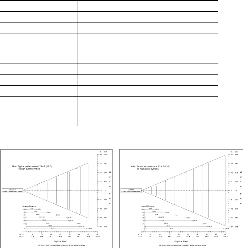
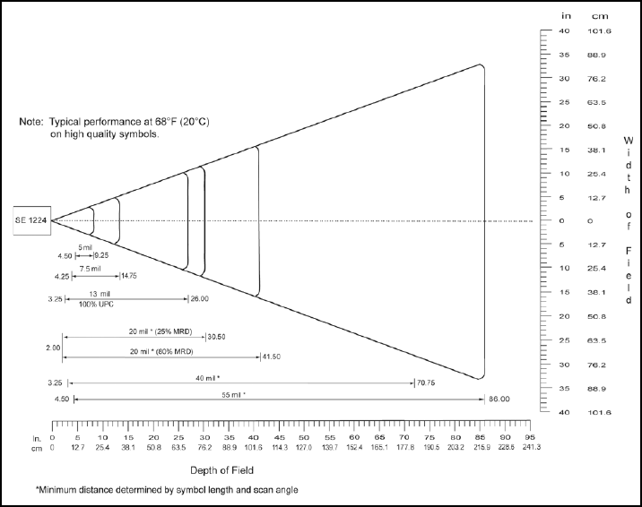
7.6.4.1 SE 1223LR Decode Zone
4,844 Lux to 86,112 Lux
Minimum Range
Inches
Width of Field
Inches
Maximum Range
Inches
Width of Field
Inches
Mil Size
10 11 2 24 5
15 7.5 1 39 8
20 7.5 1 48 10
40 10 2 90 19
55 10 2 120 24
70 reflective 48 200 40
100 reflective 60 240 48
High quality symbols in normal room light.

Chapter 7: Specifications
SE1224HP - High Performance Scanner
Psion Teklogix Omnii Hand-Held Computer User Manual 225
7.6.5 SE1224HP - High Performance Scanner
Parameter SE1224HP
Type Laser Class 2
Light Source Visible Laser Diode 650 nm
Scan Rate 35 (± 5) scans/sec (bi-directional)
Scan Angle/Field of View 42º (typical), 30º (narrow)
Scan Patterns Linear
Minimum Print Contrast Minimum 25% absolute dark/light reflectance measured at
650 nm.
Symbologies UPC/EAN, Code 128, UCC/EAN 128, RSS, Code 39, Code 93, I
2 of 5, Discrete 2 of 5, Codabar, MSI.
Programmable Parameters Laser On Time, Aim Duration, Power Mode, Trigger Mode, Bi-
directional Redundancy, Symbology types/lengths,
Data formatting.
Ambient Light Artificial: 450 ft. candles (4844 Lux).
Sunlight: 8000 ft. candles (86112 Lux).
Laser Output Power (peak) 1.35 mW
Chapter 7: Specifications
SE1224HP - High Performance Scanner
226 Psion Teklogix Omnii Hand-Held Computer User Manual
7.6.5.1 SE1224HP Decode Zones

Chapter 7: Specifications
SE1524ER – Extended Range Scanner
Psion Teklogix Omnii Hand-Held Computer User Manual 227
7.6.6 SE1524ER – Extended Range Scanner
Parameter Specification
Type Laser Class 2
Light Source Visible Laser Diode 650 nm
Scan Rate 35 (±5) scans/sec (bi-directional).
Scan Angle/Field of View 13.5° ±0.7°
Scan Patterns Linear
Minimum Print Contrast Minimum 25% absolute dark/light reflectance measured at
650 nm.
Symbologies UPC/EAN, Code 128, UCC.EAN128, RSS, Code 39, Code 93, I 2
of 5, Discrete 2 of 5, Codabar, MSI.
Programmable Parameters Laser On Time, Aim Duration, Power Mode, Trigger Mode, Bi-
directional Redundancy, Symbology types/lengths, Data format-
ting.
Ambient Light Artificial: 450 ft. candles (4,844 Lux)
Sunlight: 4,000 ft. candles (86,112 Lux).
Laser Output Power (peak) 1.26 mW
Chapter 7: Specifications
SE1524ER – Extended Range Scanner
228 Psion Teklogix Omnii Hand-Held Computer User Manual
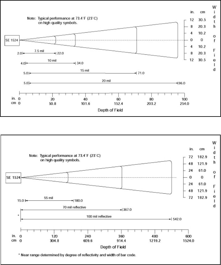
7.6.6.1 SE1524ER Decode Zones
SE1524ER Decode Zone A (Short Range, Small Codes)
SE1524ER Decode Zone B (Long Range, Large Codes)

Chapter 7: Specifications
EV15 Imager
Psion Teklogix Omnii Hand-Held Computer User Manual 229
7.6.7 EV15 Imager
7.6.7.1 EV15 Imager Decode Zone
Parameter Specification
Light Source 617 nm highly visible LED
Scan Angle 40º
Minimum Print Contrast Minimum 25%
Minimum X. Dimension 0.1 mm (4 mils)
Reading Distance Up to 90 cm (35 in)
Symbologies UPC (E&A), EAN, RSS, Code 39, Code 128, UCC/EAN 128,
ISBN, ISBT, Interleaved, Matrix, Industrial and Standard 2 of 5,
Codabar, Code 93/93i, Code 11, MSI, Plessey, Telepen, PDF417,
Micro PDF417
Ambient Light Works in any lighting conditions, from 0 to 100,000 lux
0 Lux to 100,000 Lux
Minimum Range
Inches
Maximum Range
Inches
Mil Size
52.5 7
10 3 14
UPC 2 14.5
20 2.5 22
40 3 35.5
High quality symbols in normal room light.

Chapter 7: Specifications
EA11 Decoded 2D Imager
230 Psion Teklogix Omnii Hand-Held Computer User Manual
7.6.8 EA11 Decoded 2D Imager
Parameter Specification
Scan Rate 2D mode: 56 images/s auto adaptive
Linear Emulation Mode 200 scans/s auto adaptive
Scan Angle 38.9° (horizontal), 25.4° (vertical)
Optical Resolution 752 (H) x 480 (V) pixels, 256 gray levels
Print Contrast down to 25%
Versions Standard range and high density
Symbologies - 1D
Symbologies - 2D
EAN/UPC, GS1 Databar (limited expanded & omni-directional), RSS,
Code 39, Code 128, UCC/EAN 128, ISBN, ISBT, Interleaved/Matrix/
Industrial and Standard 2 of 5, Codabar, Code 93/93i, Code 11, MSI,
Plessey, Telepen, postal codes (Australian Post, BPO, Canada Post,
Dutch Post, Japan Post, PostNet, Sweden Post)
Data Matrix, PDF417, Micro PDF 417, Codablock Maxicode, QR,
Aztec GS1 composite codes
Voltage (optics) 3.3V -5% / +10% (typical values)
Operating Current 170mA - 310mA (lighting condition dependent)
Power Saving Mode 2mA
Ambient Light Works in any lighting conditions, from 0 to 100,000 lux
Regulatory Approvals UL, VDE certified, RoHS compliant
Chapter 7: Specifications
EA11 Decoded 2D Imager
Psion Teklogix Omnii Hand-Held Computer User Manual 231
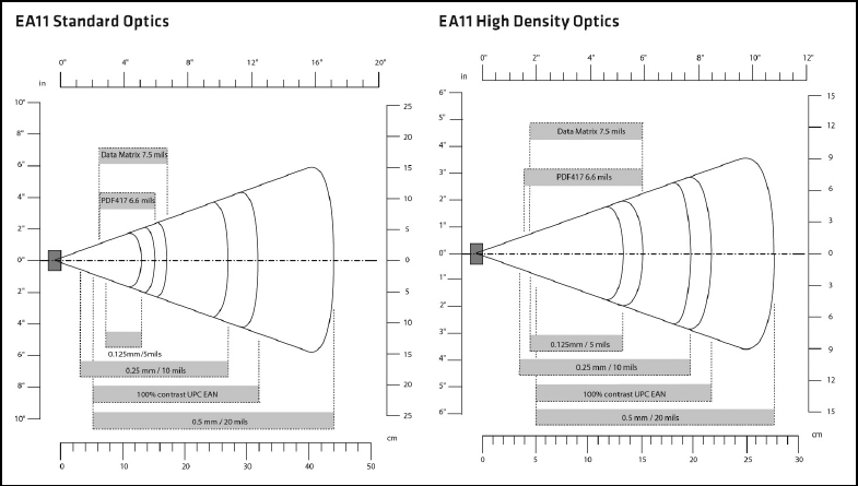
7.6.8.1 EA11 Typical Reading Distances

Chapter 7: Specifications
EA20X Imager
232 Psion Teklogix Omnii Hand-Held Computer User Manual
7.6.9 EA20X Imager
Parameter Specification
Light Source 617nm highly visible LED, 650nm laser framing/aiming
Scan Rate 2D mode: 60 images/s auto adaptive
Linear Emulation Mode 200 scans/s auto adaptive
Scan Angle 26.0° (horizontal), 16.8° (vertical)
Framing Angles 25.0° (horizontal), 16.0° (vertical)
Optical Resolution 752 (H) x 480 (V) pixels, 256 gray levels
Print Contrast down to 30% on 1D, 35% on 2D
Minimum Resolution 1D symbologies 0.15 mm (6 mil), Stacked (PDF417) 0.17 (6.6 mil) and
2D matrix 0.18 (7mil)
Symbologies - 1D
Symbologies - 2D
EAN/UPC, GS1 Databar (limited expanded & omni-directional), RSS,
Code 39, Code 128, UCC/EAN 128, ISBN, ISBT, Interleaved/Matrix/
Industrial and Standard 2 of 5, Codabar, Code 93/93i, Code 11, MSI,
Plessey, Telepen, postal codes (Australian Post, BPO, Canada Post,
Dutch Post, Japan Post, PostNet, Sweden Post)
Data Matrix, PDF417, Micro PDF 417, Codablock Maxicode, QR,
Aztec GS1 composite codes
Voltage 3.3V± 5%
Operating Current 410mA @ 3.3V scanning with power save
Power Saving Mode 7mA
Ambient Light From 0 to 100,000 lux
Regulatory Approvals UL, cUL, VDE certified, RoHS compliant, Class 2 Laser
Chapter 7: Specifications
EA20X Imager
Psion Teklogix Omnii Hand-Held Computer User Manual 233
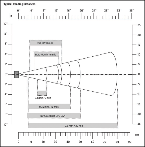
7.6.9.1 EA20X Typical Reading Distances

Chapter 7: Specifications
HHP 5080 Imager/Decoder
234 Psion Teklogix Omnii Hand-Held Computer User Manual
7.6.10 HHP 5080 Imager/Decoder
Parameter Specification
Focal Point - SR
Focal Point - SF
7 inches (17.8 cm) from lens plate
4.5 inches (11.4 cm) from lens plate
Image Sensor 752 x 480 CMOS sensor
Motion Tolerance 4 inches per second
Rotational Sensitivity 360°
Viewing Angle ±40°
Ambient Light Total darkness to 100,000 lux (full sunlight)
Illumination LEDs 626 nm ± 30 nm
Aiming LEDs: 526 nm ± 30 nm
Laser: 650 nm ± 10 nm
Input Voltage - Imager
Input Voltage - HHP 5080
3.3 VDC ± 5% (23°C)
3.0 VDC to 5.5 VDC (23°C)
Current Draw - Imager
Current Draw - HHP 5080
Max. Operating Current: 100 mA; Standby Current: 100 µA
Average Current (Interlaced Mode): 510 mA;
Standby Current: 120 µA ; Peak: 600 mA
Symbologies:
2 Dimensional
Linear
Postal
PDF417, MicroPDF417, MaxiCode, Data Matrix, QR Code,
Aztec, Aztec Mesa, Code 49, UCC Composite
Code 39, Code 128, Codabar, UPC, EAN, Interleaved 2 of 5,
Reduced Space Symbology, Code 93, Codablock
Postnet (US), Planet Code, BPO 4 State, Canadian Post,
Japanese Post, KIX (Netherlands) Post

Chapter 7: Specifications
HHP 5080 Imager/Decoder
Psion Teklogix Omnii Hand-Held Computer User Manual 235
7.6.10.1 HHP 5080 Working Range
Data is characterized at 23°C (73.4°F) and 0 lux ambient light.
Symbology Size (mil) Near Far
SR
Linear 8.3 (.020cm) 3.5 in. (8.9cm) 7.6 in. (19.3cm)
PDF417 10 (.025cm) 3.1 in. (7.9cm) 9 in. (22.9cm)
UPC 13 (.033cm) 2.1 in. (5.3cm) 13.2 in. (33.5cm)
Data Matrix 15 (.038cm) 2.3 in. (5.8cm) 10.2 in. (25.9cm)
QR 15 (.038cm) 3.1 in. (7.9cm) 8.8 in. (22.4cm)
MaxiCode 35 (.089cm) 2.0 in. (5.1cm) 13.0 in. (33cm)
SF
PDF417 6.6 (.017cm) 2.8 in. (7.1cm) 6 in. (15.2cm)
Linear 7.5 (.019cm) 2.5 in. (6.4cm) 6.5 in. (16.5cm)
Data Matrix 12.5 (.021cm) 3.4 in. (8.6cm) 5.7 in. (14.5cm)
QR 8.3 (.021cm) 3.4 in. (8.6cm) 5.4 in. (13.7cm)
Linear 10 Linear 2.2 in. (5.6cm) 7.6 in. (19.3cm)
UPC 13 (.033cm) 2.0 in. (5.1cm) 8.9 in. (22.6cm)

Appendix A: Port Pinouts
Docking Connector
Psion Teklogix Omnii Hand-Held Computer User Manual A-3
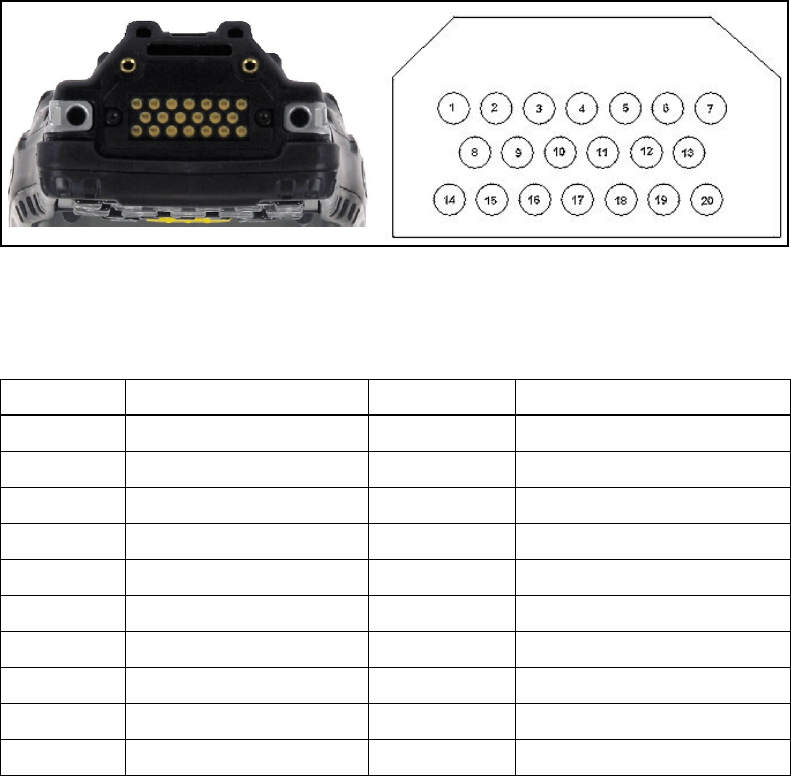
A.1 Docking Connector
The docking interface on the base of Omnii is custom-designed to dock with a device via an
array of spring-mounted pins.
The following are the pin assignments of the interface.
Table A.1 Docking Connector Pinout
Pin # Signal Pin # Signal
1 GROUND 11 USB_OTG_P
2 DC_IN 12 USB_OTG_M
3 DOCK_LOW_PWR 13 CHARGE_IN
4 GROUND 14 GROUND
5 USB_OTG_VBUS 15 DC_IN
6 CHARGE_IN 16 UART_RX
7 GROUND 17 GROUND
8DC_IN 18 UART_TX
9 USBH_P 19 CHARGE_DATA
10 USBH_M 20 GROUND
A-4 Psion Teklogix Omnii Hand-Held Computer User Manual
Appendix A: Port Pinouts
Battery Contacts
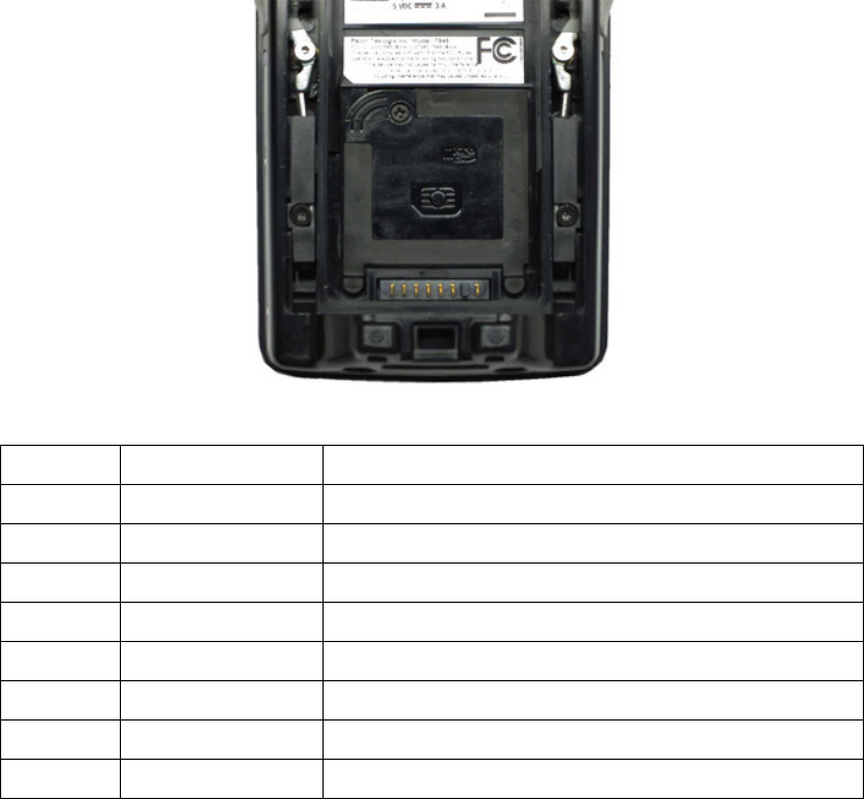
A.2 Battery Contacts
Figure A.1 Battery Contact Pinout
Pin # Signal Name Description
1 BATT-RAW Positive lead of battery.
- Plastic Rip - provides mechanical polarity.
2 BATT-RAW Positive lead of battery.
3 BATT-CLK SMBus data clock.
4 BATT-ID 0 Ω to NEG.
5 BATT-DATA SMBus bi-directional data line.
6 GND Negative lead of battery.
7 GND Negative lead of battery.
7 6 5 4 3 2 1

Psion Teklogix Omnii Hand-Held Computer User Manual B-1
APPENDIX B
WIRELESS ZERO CONFIG
B.1 Wireless Information..................................B-3
B.1.1 Wireless Statistics Tab............................B-4
B.1.2 Wireless Information Tab...........................B-4
B.2 Assigning An IP Address................................B-8
B.2.1 Name Server.................................B-8
B.3 Advanced Features...................................B-8
B.3.1 Rearranging Preferred Networks.......................B-8
B.3.2 Deleting A Preferred Network........................B-9
B.3.3 Changing Network Properties........................B-9
Appendix B: Wireless Zero Config
Wireless Information
Psion Teklogix Omnii Hand-Held Computer User Manual B-3
B.1 Wireless Information
Wireless Zero Config, the Windows native supplicant, can be used to configure the radio. To
ensure that Wireless Zero Config is activated, refer to “Wi-Fi Config: Advanced Tab” on
page 29.
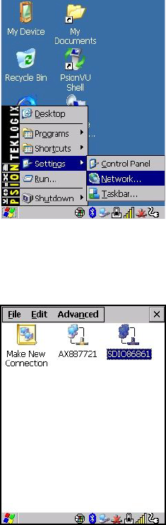
• Tap on Start>Settings>Network and Dial-up Connections.
• Choose the radio icon representing the radio you want to set up—in the sample screen
in Figure B.2, this is labelled as SDIO86861
Figure B.2 802.11 Wireless LAN Settings Window
B-4 Psion Teklogix Omnii Hand-Held Computer User Manual
Appendix B: Wireless Zero Config
Wireless Statistics Tab
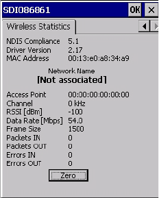
B.1.1 Wireless Statistics Tab
When you choose the Wireless LAN icon, an 802.11 Wireless LAN Settings window is
displayed. This tab lists your radio statistics. Choosing the Zero button resets the statistics of
the last four items—Packets IN, Packets OUT, IN errors and OUT errors.
Figure B.3 Wireless Statistics
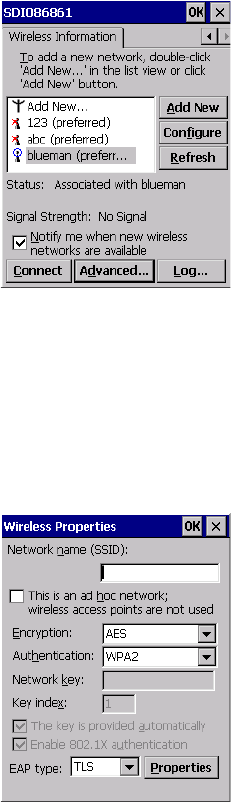
B.1.2 Wireless Information Tab
This tab displays existing networks to which you can connect, and it allows you to add a
new network or modify the settings for an existing network.
•Configure button: To change the settings in an existing network, highlight the network
you want to modify, and tap on the Configure button to display the Wireless Properties
dialog box.
•Connect button: To force connection to a specific, existing network, highlight the
network to which you want Omnii to connect, and tap on the Connect button.
Appendix B: Wireless Zero Config
Wireless Information Tab
Psion Teklogix Omnii Hand-Held Computer User Manual B-5
Figure B.4 Wireless Information Tab
This tab lists available networks—any access points that are broadcasting an SSID, and it
lists preferred networks—networks that you have configured. Since access points are gener-
ally secure, they will most likely not be listed here. By default, Omnii attempts to connect to
preferred networks. This behaviour can be changed by enabling Automatically connect to
non-preferred networks in the Advanced dialog box (see Figure B.6).
• To add a new configuration, tap on the Add New button. A blank Wireless Properties
dialog box is displayed.
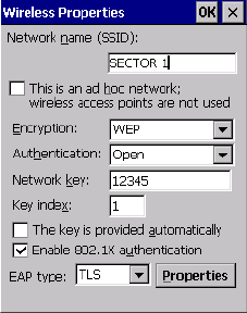
Wireless Properties
• Type the appropriate SSID (Service Set Identifier) in the Network name (SSID): dialog
box. The Network name field can contain a maximum of 32 characters. The name
assigned here is listed as a preferred network.

B-6 Psion Teklogix Omnii Hand-Held Computer User Manual
Appendix B: Wireless Zero Config
Wireless Information Tab
•Ad Hoc And Infrastructure: If you are using an Infrastructure network—one in which
the hand-helds must pass data through an access point—leave the checkbox next to This
is an ad hoc network blank.
If you are using an Ad Hoc network—a network in which the hand-helds pass data
directly to other Ad Hoc devices without an access point—add a checkmark in the
checkbox next to This is an ad hoc network to enable Ad Hoc.
•Encryption: WEP (Wired-Equivalent Privacy) encryption prevents others from acci-
dentally accessing your network. If you are not using encryption, you can choose
Disabled from the drop-down encryption menu. Otherwise, leave this field as is.
AES (Advanced Encryption Standard) is a standard for protecting data through encryp-
tion. AES supports key sizes of 128 bits, 192 bits and 256 bits and will serve as a
replacement for the Data Encryption Standard (DES), which has a key size of 56 bits. In
addition to the increased security that comes with larger key sizes, the AES algorithm is
a symmetrical block cipher that can encrypt (encipher) and decrypt (decipher)
information.
•Authentication: 802.11 supports several subtypes of network authentication services:
Open, Shared, WPA, and WPA-PSK. Under Open authentication, any wireless station
can request authentication. The station that needs to authenticate with another wireless
station sends an authentication management frame that contains the identity of the
sending station. The receiving station then sends back a frame that indicates whether it
recognizes the identity of the sending station.
Under Shared authentication, each wireless station is assumed to have received a secret
shared key over a secure channel that is independent from the 802.11 wireless network
communications channel.
Under WPA and WPA-PSK authentication, the use of 802.1x authentication is required.
For wireless networks without a Remote Authentication Dial-In User Service
(RADIUS) infrastructure, WPA supports the use of a preshared key. For wireless net-
works with a RADIUS infrastructure, Extensible Authentication Protocol (EAP) and
RADIUS is supported.
•Network Key: This text box is used to specify a 5 or 13 ASCII character sequence or an
equivalent 10 or 26 Hexadecimal digit sequence that matches the active WEP key on the
access point.
To assign a Network key, highlight The key is provided automatically, and uncheck
the checkbox to disable this option.
Important: Keep in mind that Omnii will only communicate with access points that are
configured with the same SSID.
Appendix B: Wireless Zero Config
Wireless Information Tab
Psion Teklogix Omnii Hand-Held Computer User Manual B-7
Figure B.5 Network Key and Key Index
•Key Index: This field is used to identify the WEP key.
Enter a value from 1 to 4.
•Enable 802.1x authentication: 802.1X is the IEEE standard that offers additional secu-
rity for local area networks. It provides authentication for user devices attached to an
Ethernet network, whether wired or wireless. A security protocol packet such as TLS or
MD5 encapsulated in an EAP is used in conjunction with the 802.1X standard to
authenticate users at the MAC layer. Available EAPs are listed in the drop-down menu
next to the EAP option.
To activate 802.1X, highlight 802.1x authentication, and check the checkbox.
•EAP Type (Extensible Authentication Protocol): This drop-down menu lists the EAP
types available on your system. The items in this drop-down menu will vary depending
on your network setup. Keep in mind also that some authentication protocols require
that you select a Certificate. By selecting the Properties button, you will be able to
select a Certificate. “Certificates” on page 95 provides a website that outlines how to
create certificates for your network.
•Saving and exiting the radio setup: Once you’ve completed the configuration, press
[ENTER], or tap on OK.
The connection you created will be listed in the Wireless Information tab as a preferred
network. The radio will search for the SSID and compare the WEP and authentication
information you specified. If there is a match between the hand-held settings and the
access point settings, the hand-held will communicate on the network through the
access point.
B-8 Psion Teklogix Omnii Hand-Held Computer User Manual
Appendix B: Wireless Zero Config
Assigning An IP Address
B.2 Assigning An IP Address
If your network is not using a DHCP server, you will need to assign an IP address. Refer to
“IP Address” on page 26 for details about assigning an IP address.
B.2.1 Name Server
Refer to “Name Server” on page 28 for details about this option.
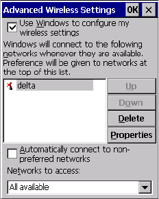
B.3 Advanced Features
To display the Advanced Wireless Settings dialog box:
• Tap on the Advanced button in the Wireless Information tab. (Refer to Figure B.4.)
This window lists the available preferred networks.
Figure B.6 Advanced Settings
B.3.1 Rearranging Preferred Networks
Omnii attempts to connect with the networks listed in this dialog box in sequence, beginning
at the top of the list. If you need to rearrange this list of networks—move networks up and
down in the list:
• Tap in the Networks List, and highlight the network that you want to move up or down
in the list.
• To move the highlighted item in the list upward or downward, tap on the Up or Down
button.
Appendix B: Wireless Zero Config
Deleting A Preferred Network
Psion Teklogix Omnii Hand-Held Computer User Manual B-9
B.3.2 Deleting A Preferred Network
To delete a network from this list:
•In the preferred networks list, highlight the network you want to remove.
• Tap on the Delete button.
B.3.3 Changing Network Properties
To change the properties of an existing preferred network:
• Highlight the network that you want to modify.
• Tap on the Properties button.
• Make any necessary changes in the Wireless Properties dialog box, and press [ENTER]
to save the changes.

Psion Teklogix Omnii Hand-Held Computer User Manual C-1
APPENDIX C
BAR CODE SETTINGS - TBD
C.1 Bar Code Settings....................................C-3
C.1.1 Scanner Options ...............................C-3
C.1.2 Restoring Default Settings..........................C-4
C.2 Decoded (Internal) Scanners..............................C-5
C.2.1 Options....................................C-5
C.2.2 Decoded (Internal) Advanced Options....................C-6
C.2.3 Decoded (Internal) Data Options.......................C-8
C.2.4 Code 39....................................C-9
C.2.5 Code 128..................................C-12
C.2.6 EAN 13...................................C-13
C.2.7 EAN 8....................................C-13
C.2.8 UPC A ...................................C-14
C.2.9 UPC E....................................C-14
C.2.10 UPC/EAN Shared Settings........................C-15
C.2.11 Code 93..................................C-16
C.2.12 Codabar..................................C-17
C.2.13 MSI Plessey................................C-17
C.2.14 Interleaved 2 of 5.............................C-19
C.2.15 Discrete 2 of 5...............................C-19
C.2.16 RSS Code (Reduced Space Symbology) .................C-20
C.2.17 Composite.................................C-21
C.2.18 PDF-417..................................C-21
C.2.19 Micro PDF-417..............................C-22
C.3 Decoded (HHP)....................................C-22
C.4 Decoded (Intermec ISCP) ..............................C-23
C.4.1 Decoded (ISCP) Options..........................C-23
C.4.2 Decoded (ISCP) Advanced Options....................C-23
C.4.3 Code 39...................................C-24
C.4.4 Code 128..................................C-26
C-2 Psion Teklogix Omnii Hand-Held Computer User Manual
C.4.5 EAN 13...................................C-27
C.4.6 EAN 8....................................C-28
C.4.7 UPC A....................................C-28
C.4.8 UPC E Settings ...............................C-29
C.4.9 UPC/EAN Shared Settings.........................C-29
C.4.10 Code 93...................................C-30
C.4.11 Codabar...................................C-31
C.4.12 MSI Plessey................................C-32
C.4.13 Code 11...................................C-33
C.4.14 Interleaved 2 of 5..............................C-33
C.4.15 Matrix 2 of 5................................C-34
C.4.16 Discrete 2 of 5...............................C-35
C.4.17 Telepen...................................C-35
C.4.18 RSS Code (Reduced Space Symbology)..................C-36
C.4.19 Composite.................................C-37
C.4.20 TLC-39...................................C-37
C.4.21 PDF-417..................................C-38
C.4.22 Micro PDF-417...............................C-38
C.4.23 Codablock.................................C-39
C.5 Non-Decoded Scanners................................C-39
C.5.1 Options ...................................C-40
C.5.2 Code 39...................................C-41
C.5.3 Code 128...................................C-42
C.5.4 EAN 13...................................C-43
C.5.5 EAN 8....................................C-44
C.5.6 UPC A....................................C-45
C.5.7 UPC E....................................C-45
C.5.8 Codabar...................................C-46
C.5.9 Code 93...................................C-47
C.5.10 Code 11...................................C-47
C.5.11 Interleaved 2 of 5..............................C-48
C.5.12 MSI Plessey................................C-48
C.5.13 Discrete 2 of 5...............................C-49
C.5.14 IATA 2 of 5.................................C-50
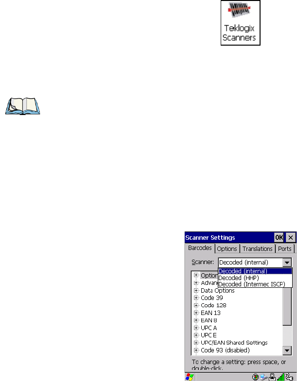
Psion Teklogix Omnii Hand-Held Computer User Manual C-3
C.1 Bar Code Settings
The Teklogix Scanners icon in the Control Panel provides dialog boxes in which you can
tailor bar code scanner configurations and choose the bar codes your scanner will recognize.
The parameters are preset with the default settings of the decoded scanner installed in the
unit. For a listing of available scanners and their specifications, please refer to Chapter 7:
“Specifications”.
C.1.1 Scanner Options
The drop-down menu to the right of the Scanner option allows you to choose configurations
for one of the following scanner types, depending on what is installed in/on your hand-held:
Decoded (internal), Decoded (HHP), Decoded (Intermec ISCP, and Non-decoded Scanners.
The symbologies listed change to reflect the scanner you choose and the bar codes it sup-
ports. Always defer to your bar code scanner’s programming manual when in doubt about
the availability or settings for any parameter.
Note: To enable a newly-installed scanner, press and hold down the [FN] key and the
[ENTER/Power] key simultaneously for a minimum of three seconds.
For information on configuring the Options, Translations, and Ports settings, see
“Teklogix Scanners” on page 158.
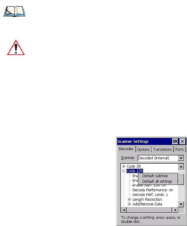
Keep in mind that some bar code types are only available when an internal imaging scanner
is installed. All internal scanners can be configured using these dialog boxes.
C.1.2 Restoring Default Settings
If you want to restore the factory defaults after making changes, the defaults can be applied
to a selected parameter, sub-tree of parameters, or all scanner parameters.
• Press and hold on a symbology (e.g., Code 128) to display a pop up a menu.
• Choose Default subtree to reset only the parameters in the symbology you selected, or
choose Default all settings to reset all scanner parameters to default settings.
To reset a single parameter to its default setting:
• Press and hold on the parameter you want to reset.
Note: Your Omnii comes preconfigured from the factory for internal scanner types. The
type of scanner installed can be determined from the System icon in the Control
Panel, under the System Properties tab.
Important: To improve the decode speed and performance, enable (set to ‘on’) only
those codes that are required by the application.
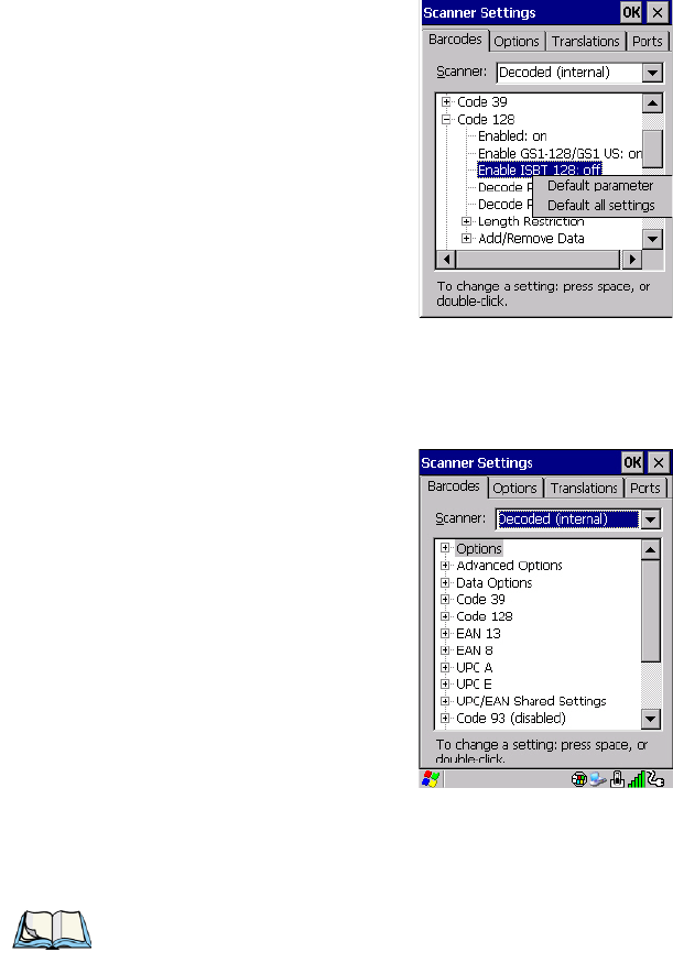
Appendix C: Bar Code Settings - TBD
Decoded (Internal) Scanners
Psion Teklogix Omnii Hand-Held Computer User Manual C-5
• Choose Default parameter to reset the parameter to the default setting.
C.2 Decoded (Internal) Scanners
• Tap on the Scanner drop-down menu, and choose Decoded (internal).
C.2.1 Options
Dot Time (msec)
The value selected for Dot Time (msec) determines (in milliseconds) how long the targeting
dot remains on before the scanner switches to a normal scan sweep. When you double-tap
Note: Some options are available only for specific scanners. Refer to the option names in
this section for scanner model identification.
C-6 Psion Teklogix Omnii Hand-Held Computer User Manual
Appendix C: Bar Code Settings - TBD
Decoded (Internal) Advanced Options
on this parameter, a dialog box is displayed in which you can enter a value of 0 msec, 200
msec or 400 msec. A value of 0 (zero) disables the target dot.
Laser On Time
The value assigned to this parameter determines how long the laser will remain on when the
scan button or trigger is pressed.
Double-tapping on this parameter displays a dialog box in which you can enter a value
between 5 and 99. The value is measured in tenths of seconds.
C.2.2 Decoded (Internal) Advanced Options
Scan Mode
You can set the method of scanning by setting this parameter to Scan beam only, Aim with
Scan: 1 trigger pull, Aim with Scan: 2 trigger pulls, Aim with Scan on trigger release, and
Continuous Scan Mode. Default is Scan beam only.
Aim Duration
This parameter determines the total time the aiming pattern appears before the scanner laser
begins sweeping. When you double-tap on this parameter, a dialog box is displayed in which
you can enter a value from 0 to 30 (0 to 3 sec.). A value of 0 (zero) disables the aiming-dot.
Minimum Cancel Time
The value assigned to this parameter determines the time delay before the scanner is turned
off, once the scanner trigger or button is released. This gives the scanner a minimum amount
of time to complete its current decode before the scan is cancelled when you quickly trigger
on/off.
Power Mode
This parameter is a power-saving option. Tapping on it displays a screen listing two power
mode options: Continuous Power and Low Power.
In Continuous Power mode, the scanner is always on, waiting for a trigger pull or serial
communication.
In Low Power mode, the scanner is in a standby state, drawing minimal power until a trigger
pull or serial communication wakes it. Keep in mind that while this option is more suitable
for battery powered applications, there will be a slight delay while the scanner powers up to
scan a bar code.

Psion Teklogix Omnii Hand-Held Computer User Manual C-7
Appendix C: Bar Code Settings - TBD
Decoded (Internal) Scanners
Decoded (Internal) Advanced Options
Low Power Timeout
To extend laser life, you can select the time the scanner remains active following a success-
ful decode. The scanner wakes from low power mode when a bar code is scanned—a
successful decode restores normal flashing.
This is only used if the unit’s Trigger Mode has been changed to Continuous On. If the
unit is used in a fixed mount this parameter might be used, but not if the unit is used as
a hand-held.
When you double-tap on this parameter, a dialog box is displayed in which you can choose a
value of 30 sec., 1 min., 2 min. or 3 min.
Parameter Scanning
Setting this parameter to on enables decoding of parameter bar codes.
Linear Security Level
This parameter allows you to select the security level appropriate for your bar code quality.
There are four levels of decode security for linear code types (e.g., Code 39,
Interleaved 2 of 5). Higher security levels should be selected for decreasing levels of bar
code quality. As security levels increase, the scanner’s decode speed decreases.
Double-tapping on this parameter displays a dialog box in which you can enter a value from
1 to 4.
Linear security level 1 specifies that the following code types must be successfully read
twice before being decoded:
Linear security level 2 specifies that all types of codes must be successfully read twice
before being decoded.
Note: This parameter is only used if the Trigger Mode has been set to Continuous On and
Omnii is mounted in a fixed position; otherwise, ‘Low Power Timeout’ is not used.
Code Type Length
Codabar All
MSI Plessey 4 or less
D 5 of 5 8 or less
I 2 of 5 8 or less

C-8 Psion Teklogix Omnii Hand-Held Computer User Manual
Appendix C: Bar Code Settings - TBD
Decoded (Internal) Scanners
Decoded (Internal) Data Options
Linear security level 3 specifies that code types other than the following must be success-
fully read twice before being decoded. The following codes must be read three times:
Linear security level 4 requires that all code types be successfully read three times before
being decoded.
Bi-Direction Redundancy
When this parameter is enabled, a bar code must be successfully scanned in both directions
(forward and reverse) before being decoded.
C.2.3 Decoded (Internal) Data Options
Transmit Code ID Char
A code ID character identifies the scanned bar code type. In addition to any single character
prefix already selected, the code ID character is inserted between the prefix and the decoded
symbol.
When you double-tap on this parameter, a dialog box is displayed in which you can choose a
transmit code: None, AIM or Symbol.
Scan Data Format
This parameter allows you to change the scan data transmission format.
Double-tapping on Scan Data Format displays the following options from which you can
choose a data format: data (as-is), data [S1], data [S2], data [S1][S2], [P] data, [P] data
[S1], [P] data [S2] and [P] data [S1][S2].
Code Type Length
MSI Plessey 4 or less
D 2 of 5 8 or less
I 2 of 5 8 or less
Note: This parameter is only valid if a “Linear Security Level” is enabled.

Psion Teklogix Omnii Hand-Held Computer User Manual C-9
Appendix C: Bar Code Settings - TBD
Decoded (Internal) Scanners
Code 39
Prefix [P], Suffix [S1] and Suffix [S2]
A prefix and/or one or two suffixes may be appended to scan data for use in data editing.
When you double-tap on these parameters, dialog boxes are displayed in which you can
enter a value from 0 to 255.
Delete Char Set ECIs
Setting this parameter to on enables the scanner to delete any escape sequences representing
Character Set ECIs (Extended Channel Interpretations [also known as GLIs]) from its buffer
before transmission.
When this parameter is enabled, the scanner transmits data from PDF417 and MicroPDF417
bar codes containing Character Set ECIs, even when the ECI Protocol is disabled.
ECI Decoder
Setting this parameter to on enables the scanner to interpret any Extended Channel Interpre-
tations (ECIs) supported by the scanner. This parameter has no effect on symbols that were
not encoded using ECIs.
If this parameter is set to off and a symbol that was encoded using an ECI escape is scanned,
the scanner transmits the ECI escape followed by the uninterpreted data.
C.2.4 Code 39
Enabled
Setting this parameter to on enables “Code 39”.
Enable Trioptic Code 39
Trioptic Code 39 symbols always contain six characters. Setting this parameter to on allows
this type of symbology to be recognized.
Convert To Code 32
Setting this parameter to on allows the scanner to convert the bar code from “Code 39” to
“Code 32”.
Note: “Trioptic Code 39” and “Full ASCII” should not be enabled simultaneously. The
scanner does not automatically discriminate between these two symbologies.
Note: “Code 39” must be enabled in order for this parameter to function.
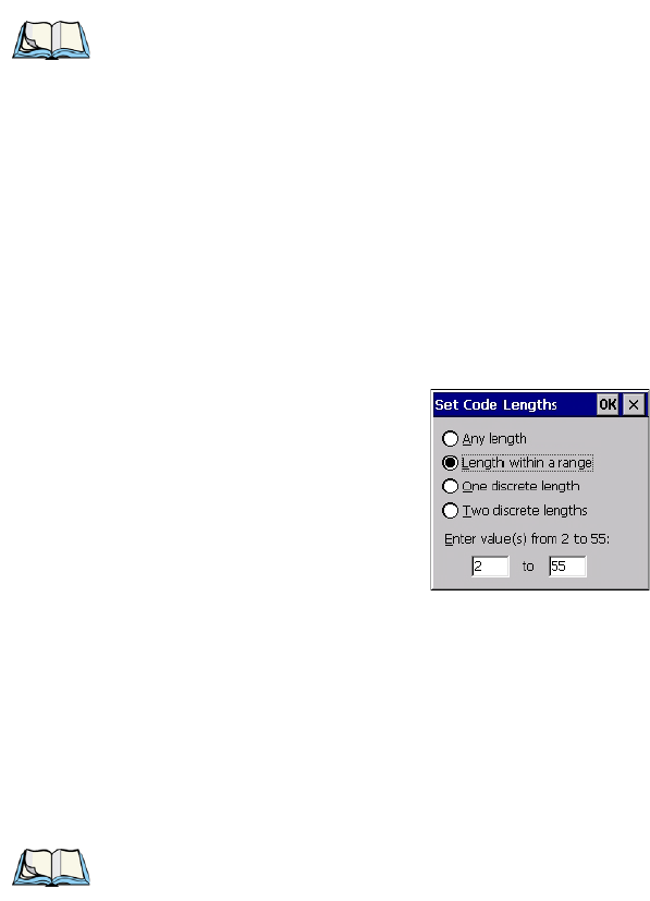
C-10 Psion Teklogix Omnii Hand-Held Computer User Manual
Appendix C: Bar Code Settings - TBD
Decoded (Internal) Scanners
Code 39
Code 32 Prefix
When this parameter is enabled, the prefix character “A” is added to all “Code 32”
bar codes.
Set Length L1 and Set Length L2
Lengths for “Code 39” can be set for Any length, Length within a range, One discrete length
or Two discrete lengths. The length of a code refers to the number of characters (i.e., human
readable characters), including check digit(s).
Double-tapping on these parameters displays dialog boxes labelled Set Code Lengths where
you can define the code length that will be decoded by your scanner.
Choosing One discrete length allows you to decode only those codes containing a selected
length. Choosing Two discrete lengths allows you to decode only those codes containing two
selected lengths. Length within a range allows you to decode a code type within a specified
range from 2 to 55.
Check Digit Verification
When this parameter is enabled, the integrity of a “Code 39” symbol is checked to ensure
that it complies with specified algorithms.
Transmit Check Digit
If the check digit is to be transmitted with the data, this parameter must be enabled.
Note: “Convert to Code 32” must be enabled in order for this parameter to function.
Note: Only those “Code 39” symbols that include a MOD 43 check digit are decoded
when this parameter is enabled.
Psion Teklogix Omnii Hand-Held Computer User Manual C-11
Appendix C: Bar Code Settings - TBD
Decoded (Internal) Scanners
Code 39
Full ASCII
If this parameter is enabled, the characters +, %, and / are used as escape characters. The
combination of an escape character and the next character is converted to an equivalent
ASCII character.
Decode Performance
If this parameter is enabled, one of three decode levels can be chosen in the Decode Perfor-
mance Level parameter.
Decode Perf. Level
This parameter provides three levels of decode performance or “aggressiveness” for Code
39 symbols. Increasing the performance level reduces the amount of required bar code ori-
entation—this is useful when scanning very long and/or truncated bar codes. Keep in mind
that increased levels reduce decode security.
When you double-tap on this parameter, a dialog box is displayed in which you can enter a
decode performance level of between 1 and 3.
Length Restriction
The parameters in this sub-menu allow you to define the length of the bar codes that will be
decoded using either the Field Size parameter or the Minimum Size and Maximum Size pa-
rameters (see below). The order of operation to either match the Field Size or determine if
the length falls between the Minimum Size and Maximum Size is as follows:
• Strip the leading and trailing characters.
• Add the prefix and suffix characters.
• Count the number of characters remaining to either match the field size or determine if
the length falls between the minimum and maximum size.
Field Size
When a value is assigned for this parameter, only bar codes that match the field size exactly
can be transmitted. If a value is assigned to this parameter, a Minimum Size and Maximum
Size value is not required.
Minimum Size and Maximum Size
When a value is assigned to these parameters, only bar code lengths that fall between the
minimum and maximum value can be decoded. If values are assigned to these parameters, a
Field Size value is not required.

C-12 Psion Teklogix Omnii Hand-Held Computer User Manual
Appendix C: Bar Code Settings - TBD
Decoded (Internal) Scanners
Code 128
Add/Remove Data
Prefix Char
This character, if non-zero, is added before a successfully decoded bar code. Press the key
you want to insert in the dialog box attached to this parameter. The ASCII/Unicode key
value of the keypress is displayed.
Suffix Char
This character, if non-zero, is added after a successfully decoded bar code. Press the key you
want to insert in the dialog box attached to this parameter. The ASCII/Unicode key value of
the keypress is displayed.
Strip Leading
This parameter determines the number of characters that will be removed from the begin-
ning of the bar code before the prefix character is added.
Strip Trailing
The value entered in this parameter determines the number of characters that will be
removed from the end of the bar code before the suffix character is added.
C.2.5 Code 128
Enabled
Set this parameter to on to enable “Code 128”.
Enable GS1-128/GS1 US
Previously UPC/EAN and UCC, the GS1-128/GS1 US types of bar code include group sep-
arators and start codes.
Enable ISBT 128
To successfully scan this type of bar code, this option must be set to on.
Decode Performance
If this parameter is set to on, one of three decode levels assigned to the Decode Performance
Level parameter can be selected.
Note: For Code 39 bar codes, the “AIAG Strip” is performed before the “Strip Leading”.
Psion Teklogix Omnii Hand-Held Computer User Manual C-13
Appendix C: Bar Code Settings - TBD
Decoded (Internal) Scanners
EAN 13
Decode Perf. Level
This parameter provides three levels of decode performance or “aggressiveness” for Code
128 symbols. Increasing the performance level reduces the amount of required bar code ori-
entation, allowing you to scan at an angle horizontal to the bar code. This is useful when
scanning very long and/or truncated bar codes. Keep in mind that increased levels reduce
decode security. There is a limitation that it can only be used with one fixed length.
When you double-tap on this parameter, a dialog box is displayed in which you can enter a
decode performance level of between 1 and 3.
Length Restriction
Refer to “Length Restriction” on page C-11 for details.
Add/Remove Data
Refer to “Add/Remove Data” on page C-12 for details.
C.2.6 EAN 13
Enabled
Set this parameter to on to enable “EAN 13”.
Add/Remove Data
Refer to “Add/Remove Data” on page C-12 for details.
C.2.7 EAN 8
Enabled
Set this parameter to on to enable “EAN 8”.
EAN-8 Zero Extend
When this parameter is enabled, five leading zeros are added to decoded EAN-8 symbols,
making them compatible in format to EAN-13 symbols. Disabling this parameter returns
EAN-8 symbols to their normal format.
Add/Remove Data
Refer to “Add/Remove Data” on page C-12 for details.
C-14 Psion Teklogix Omnii Hand-Held Computer User Manual
Appendix C: Bar Code Settings - TBD
Decoded (Internal) Scanners
UPC A
C.2.8 UPC A
Enabled
Set this parameter to on to enable “UPC A”.
UPC-A, Check Digit
If you enable this parameter, the check digit is included with the decoded bar code data.
UPC-A, Preamble
When you double-tap on this parameter, a dialog box is displayed where you can choose one
of three options for lead-in characters for UPC-A symbols transmitted to the host device:
System Char—system character transmitted with the data,
Country Code and System Char—both the country code (“0” for USA) and system
character are transmitted with the data, or
None—no preamble is transmitted. The lead-in characters are considered part of
the symbol.
Add/Remove Data
Refer to “Add/Remove Data” on page C-12 for details.
C.2.9 UPC E
Enabled UPC-E
Set this parameter to on to allow “UPC E” bar code scans.
Enabled UPC-E1
Set this parameter to on to allow “UPC-E1” (zero suppressed) bar code scans.
UPC-E and UPC-E1 Check Digit
If you enable one or both of these parameters, a check digit is included with the decoded bar
code data.
UPC-E and UPC-E1 Preamble
When you double-tap on one of these parameters, a dialog box is displayed where you can
choose one of three options for lead-in characters for UPC-E and UPC-E1 symbols transmit-
ted to the host device:
System Char—system character transmitted with the data,
Psion Teklogix Omnii Hand-Held Computer User Manual C-15
Appendix C: Bar Code Settings - TBD
Decoded (Internal) Scanners
UPC/EAN Shared Settings
Country Code and System Char—both the country code (“0” for USA) and system
character are transmitted with the data, or
None—no preamble is transmitted. The lead-in characters are considered part of
the symbol.
Conv. UPC-E To UPC-A
This parameter converts UPC-E (zero suppressed) decoded data to UPC-A format before
transmission. After conversion, data follows UPC-A format and is affected by UPC-A pro-
gramming selections (e.g., Preamble, Check Digit).
Conv. UPC-E1 To UPC-A
This parameter converts UPC-E1 (zero suppressed) decoded data to UPC-A format before
transmission. After conversion, data follows UPC-A format and is affected by UPC-A pro-
gramming selections (e.g., Preamble, Check Digit).
Add/Remove Data
Refer to “Add/Remove Data” on page C-12 for details.
C.2.10 UPC/EAN Shared Settings
The parameters you set here are a shared across all available UPC and EAN bar codes.
Enable Bookland EAN
Setting this parameter to on allows your scanner to recognize Bookland EAN bar codes.
Supplementals
Supplementals are additionally appended characters (2 or 5).
Double-tapping this parameter displays a list of options. If Ignore is chosen, UPC/EAN is
decoded and the supplemental characters are ignored. If Decode is chosen, UPC/EAN
symbols are decoded with supplementals. Autodiscriminate works in conjunction with the
Supp. Redundancy parameter.
Supp. Redundancy
With “Autodiscriminate” selected in the Supplementals parameter, Supp. Redundancy
adjusts the number of times a symbol without supplementals is decoded before transmission.
When you double-tap on this parameter, a dialog is displayed in which you can enter a value
between 2 and 20. A value of 5 or above is recommended when Autodiscriminate is selected
and you are decoding a mix of UPC/EAN symbols with and without supplementals.
C-16 Psion Teklogix Omnii Hand-Held Computer User Manual
Appendix C: Bar Code Settings - TBD
Decoded (Internal) Scanners
Code 93
Security Level
This parameter controls the tolerance for decoding edge-to-edge UPC/EAN bar codes.
Double-tapping on this parameter displays a dialog box in which you can choose a level
from 0 to 3. Lower values have a lower tolerance for misreads, but they also increase the
time it takes to decode the bar code.
Linear Decode
Linear Decode applies to code types containing two adjacent blocks (e.g., UPC-A, EAN-8,
EAN-13). When enabled (set to on), a bar code is transmitted only when both the left and
right blocks are successfully decoded within one laser scan. This option should be enabled
when bar codes are in proximity to each other.
2D UPC Half Block Stitching
Setting this parameter to on enables “UPC Half Block Stitching” for an omnidirectional
engine only.
C.2.11 Code 93
Enabled
Set this parameter to on to enable “Code 93”.
Set Length L1 and Set Length L2
Lengths for “Code 93” can be set for Any Length, Length within a range, One discrete
length or Two discrete lengths. The length of a code refers to the number of characters
(i.e., human readable characters), including check digit(s).
Double-tapping on this parameter displays a dialog box labelled Set Code Lengths where
you can define the code length that will be recognized by your scanner.
Choosing One discrete length allows you to decode only those bar codes of a specified
length. Choosing Two discrete lengths allows you to specify two lengths of bar codes that
may be decoded. Length within a range allows you to decode any bar code with a length that
falls within a specified range (e.g. between 10 and 15 characters). The minimum and
maximum values for the range are 4 and 55, respectively.
Length Restriction
Refer to “Length Restriction” on page C-11 for details.
Add/Remove Data
Refer to “Add/Remove Data” on page C-12 for details.

Psion Teklogix Omnii Hand-Held Computer User Manual C-17
Appendix C: Bar Code Settings - TBD
Decoded (Internal) Scanners
Codabar
C.2.12 Codabar
Enabled
Set this parameter to on to enable “Codabar”.
Set Length L1 and Set Length L2
Lengths for “Codabar” can be set for Any length, Length within a range, One discrete length
or Two discrete lengths. The length of a code refers to the number of characters (i.e., human
readable characters), including check digit(s).
Double-tapping on this parameter displays a dialog box labelled Set Code Lengths where
you can define the code length that will be recognized by your scanner.
Choosing One discrete length allows you to decode only those bar codes of a specified
length. Choosing Two discrete lengths allows you to specify two lengths of bar codes that
may be decoded. Length within a range allows you to decode any bar code with a length that
falls within a specified range (e.g. between 10 and 15 characters). The minimum and
maximum values for the range are 5 and 55, respectively.
CLSI Editing
When enabled, this parameter strips the start and stop characters and inserts a space after the
first, fifth, and tenth characters of a 14-character Codabar symbol.
NOTIS Editing
When enabled, this parameter strips the start and stop characters from decoded
Codabar symbol.
Length Restriction
Refer to “Length Restriction” on page C-11 for details.
Add/Remove Data
Refer to “Add/Remove Data” on page C-12 for details.
C.2.13 MSI Plessey
Enabled
Set this parameter to on to enable “MSI Plessey”.
Note: Symbol length does not include start and stop characters.

C-18 Psion Teklogix Omnii Hand-Held Computer User Manual
Appendix C: Bar Code Settings - TBD
Decoded (Internal) Scanners
MSI Plessey
Set Length L1 and Set Length L2
Lengths for “MSI Plessey” can be set for Any length, Length within a range, One discrete
length or Two discrete lengths. The length of a code refers to the number of characters (i.e.,
human readable characters), including check digit(s).
Double-tapping on this parameter displays a dialog box labelled Set Code Lengths where
you can define the code length that will be recognized by your scanner.
Choosing One discrete length allows you to decode only those bar codes of a specified
length. Choosing Two discrete lengths allows you to specify two lengths of bar codes that
may be decoded. Length within a range allows you to decode any bar code with a length that
falls within a specified range (e.g. between 10 and 15 characters). The minimum and
maximum values for the range are 6 and 55, respectively.
Check Digits
Double-tapping on this parameter displays a dialog box in which you can choose One or
Two check digit(s).
If this parameter is set to One, it is assumed that the last digit is a check digit. If “Check
Digits” is set to Two, it is assumed that the last two digits are check digits.
Transmit Check Digit
If this parameter is enabled, the check digit is included with the bar code data.
Check Digit Algorithm
When the Two MSI Plessey check digits option is selected, an additional verification is re-
quired to ensure integrity. Double-tapping on this parameter displays a dialog box in which
you can choose the algorithm to be used: MOD 10/MOD 11 or MOD 10/MOD 10.
Length Restriction
Refer to “Length Restriction” on page C-11 for details.
Add/Remove Data
Refer to “Add/Remove Data” on page C-12 for details.
Note: If Two check digits is selected, an MSI Plessey “Check Digit Algorithm” must also
be selected. See below for details.
Psion Teklogix Omnii Hand-Held Computer User Manual C-19
Appendix C: Bar Code Settings - TBD
Decoded (Internal) Scanners
Interleaved 2 of 5
C.2.14 Interleaved 2 of 5
Enabled
Set this parameter to on to enable “Interleaved 2 of 5”.
Set Length L1 and Set Length L2
Lengths for “Interleaved 2 of 5” can be set for Any length, Length within a range, One dis-
crete length or Two discrete lengths. The length of a code refers to the number of characters
(i.e., human readable characters), including check digit(s).
Double-tapping on this parameter displays a dialog box labelled Set Code Lengths where
you can define the code length that will be recognized by your scanner.
Choosing One discrete length allows you to decode only those bar codes of a specified
length. Choosing Two discrete lengths allows you to specify two lengths of bar codes that
may be decoded. Length within a range allows you to decode any bar code with a length that
falls within a specified range (e.g. between 10 and 15 characters). The minimum and
maximum values for the range are 4 and 14, respectively.
Check Digit Verification
When enabled, this parameter checks the integrity of an I 2 of 5 symbol to ensure it complies
with a specified algorithm: either USS (Uniform Symbology Specification) or OPCC (Opti-
cal Product Code Council).
Transmit Check Digit
If this parameter is enabled, the check digit is included with the bar code data.
Convert To EAN 13
If this parameter is enabled, an I 2 of 5 bar code is converted to EAN 13.
Length Restriction
Refer to “Length Restriction” on page C-11 for details.
Add/Remove Data
Refer to “Add/Remove Data” on page C-12 for details.
C.2.15 Discrete 2 of 5
Enabled
Set this parameter to on to enable “Discrete 2 of 5”.
C-20 Psion Teklogix Omnii Hand-Held Computer User Manual
Appendix C: Bar Code Settings - TBD
Decoded (Internal) Scanners
RSS Code (Reduced Space Symbology)
Set Length L1 and Set Length L2
Lengths for “Discrete 2 of 5” can be set for Any length, Length within a range, One discrete
length or Two discrete lengths. The length of a code refers to the number of characters (i.e.,
human readable characters), including check digit(s).
Double-tapping on this parameter displays a dialog box labelled Set Code Lengths where
you can define the code length that will be recognized by your scanner.
Choosing One discrete length allows you to decode only those bar codes of a specified
length. Choosing Two discrete lengths allows you to specify two lengths of bar codes that
may be decoded. Length within a range allows you to decode any bar code with a length that
falls within a specified range (e.g. between 10 and 15 characters). The minimum and
maximum values for the range are 1 and 12, respectively.
Length Restriction
Refer to “Length Restriction” on page C-11 for details.
Add/Remove Data
Refer to “Add/Remove Data” on page C-12 for details.
C.2.16 RSS Code (Reduced Space Symbology)
Enable
Setting any of these parameters to on enables “2D RSS Code” scanning capability.
Enable RSS-14 (Reduced Space Symbology)
RSS-14 code can be either purely linear or split in half with one half stacked on top of the
other half. Stacking the code reduces the bar code length, and providing the nominal height
of the code is maintained, it can be omni-directionally scanned.
Enable RSS Limited
“RSS-Limited” is restricted, in that it can only encode 14 digit GTINs (global trade item
number) that begin with either a 0 or a 1. It is not stackable and is not designed to be read
omni-directionally.
Enable RSS Expanded
“RSS Expanded” uses the same application identifiers as UCC/EAN-128 codes but it can be
split into sections and stacked several rows high, reducing the length of the symbol, while
increasing the capacity of data that can be stored. “RSS Expanded” code can be omni-
directionally scanned.

Psion Teklogix Omnii Hand-Held Computer User Manual C-21
Appendix C: Bar Code Settings - TBD
Decoded (Internal) Scanners
Composite
Length Restriction
Refer to “Length Restriction” on page C-11 for details.
Add/Remove Data
Refer to “Add/Remove Data” on page C-12 for details.
C.2.17 Composite
A composite symbol includes multi-row 2D components making it compatible with linear
and area CCD scanners along with linear and rastering laser scanners. The options available
for this parameter represent multi-level components of a composite symbol.
Enable CC-C and Enable CC-AB
To activate these components, set the parameters to on.
Enable TLC-39
This composite component integrates MicroPDF417 with the linear code. Setting this pa-
rameter to on enables this parameter.
C.2.18 PDF-417
Enabled
Setting this parameter to on enables PDF-417 two dimensional (2D) coding.
Length Restriction
Refer to “Length Restriction” on page C-11 for details.
Add/Remove Data
Refer to “Add/Remove Data” on page C-12 for details.
Important: To successfully read this type of bar code, the two types of symbologies
included in a composite bar code must be enabled.
C-22 Psion Teklogix Omnii Hand-Held Computer User Manual
Appendix C: Bar Code Settings - TBD
Decoded (HHP)
Micro PDF-417
C.2.19 Micro PDF-417
Enabled
Setting this parameter to on enables “2D Micro PDF-417” bar code scanning. Micro PDF-
417 is a multi-row symbology that is useful for applications requiring greater area efficiency
but lower data capacity than PDF-417.
Code 128 Emulation
When this parameter is enabled, the scanner transmits data from certain Micro PDF-417
symbols as if it was encoded in Code 128 symbols.
If Code 128 Emulation is enabled, the following Micro PDF-417 symbols are transmitted
with one of the following prefixes:
]C1 if the first codeword is 903-907, 912, 914, 915
]C2 if the first codeword is 908 or 909
]C0 if the first codeword is 910 or 911
If Code 128 Emulation is set to off, the Micro PDF-417 symbols are transmitted with one of
the following prefixes:
]L3 if the first codeword is 903-907, 912, 914, 915
]L4 if the first codeword is 908 or 909
]L5 if the first codeword is 910 or 911
Length Restriction
Refer to “Length Restriction” on page C-11 for details.
Add/Remove Data
Refer to “Add/Remove Data” on page C-12 for details.
C.3 Decoded (HHP)
To configure imagers, please see Appendix D: “Teklogix Imagers Applet”.
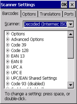
Psion Teklogix Omnii Hand-Held Computer User Manual C-23
Appendix C: Bar Code Settings - TBD
Decoded (Intermec ISCP)
Decoded (ISCP) Options
C.4 Decoded (Intermec ISCP)
• Tap on the Scanner drop-down menu, and choose Decoded (Intermec ISCP).
C.4.1 Decoded (ISCP) Options
Laser On Time
The value assigned to this parameter determines how long the laser will remain on when the
scan button or trigger is pressed.
Double-tapping on this parameter displays a dialog box in which you can enter a value
between 1 and 10 seconds.
C.4.2 Decoded (ISCP) Advanced Options
Continuous Scan Mode
Setting this parameter to on keeps the laser on and continuously decoding as long as the
scanner button is pressed and held down.
Minimum Cancel Time
The value assigned to this parameter determines the time delay before the scanner is turned
off, once the scanner trigger or button is released. This gives the scanner a minimum amount
of time to complete its current decode before the scan is cancelled when you quickly trigger
on/off.

C-24 Psion Teklogix Omnii Hand-Held Computer User Manual
Appendix C: Bar Code Settings - TBD
Decoded (Intermec ISCP)
Code 39
Low Power Timeout
To extend laser life, you can select the time the scanner remains active following a success-
ful decode. The scanner wakes from low power mode when a bar code is scanned—a
successful decode restores normal flashing.
When you double-tap on this parameter, a dialog box is displayed in which you can choose a
value of 30 sec, 1 min, 2 min, or 3 min.
Parameter Scanning
Setting this parameter to Enabled allows decoding of parameter bar codes.
Same Read Validate
The data is only transmitted after repeated reads give the same result. The value assigned at
this parameter determines the number of reads required, from 0 to 10 times.
Same Read Timeout
Prevents the same bar code from being read more than once. The value assigned determines
after what time period the scanner will timeout, from 0 to 2550 msec.
Diff Read Timeout
Prevents unwanted reading of other bar codes on the same label. The value assigned deter-
mines after what time period the scanner will timeout, from 0 to 2550 msec.
Add AIM ID Prefix
The AIM ID (Association for Automatic Identification and Mobility) is an international bar
code identifier. When this parameter is enabled, the AIM ID is inserted at the beginning of
the decoded bar code.
C.4.3 Code 39
Enable
Setting this parameter to on enables “Code 39”.
Note: This parameter is only used if the Trigger Mode has been set to Continuous On and
the unit is mounted in a fixed position; otherwise, ‘Low Power Timeout’ is not used.

Psion Teklogix Omnii Hand-Held Computer User Manual C-25
Appendix C: Bar Code Settings - TBD
Decoded (Intermec ISCP)
Code 39
Full ASCII
If this parameter is enabled, the characters +, %, and / are used as escape characters. The
combination of an escape character and the next character is converted to an equivalent
ASCII character.
Reading Range
Determines the reading distance from which a bar code can be successfully scanned. The
default setting, Extended, allows for increased reading distance.
Start/Stop Transmit
Setting this parameter to on enables the transmission of start and stop characters, which are
usually not transmitted. Code 39 can start and end with either a * or a $ character (see also
the next parameter).
Accepted Start Char
This parameter allows you the option of using one of the two start/stop characters or both ($
char, * char, $ and * char).
Check Digit Verification
Uses the specified algorithm of the option you've chosen to ensure the integrity of the
symbol data before transmitting. If the data does not contain that algorithm, the data is not
transmitted. The available options are: Disabled, MOD 43 Check, French CIP, or
Italian CIP.
Transmit Check Digit
If the check digit is to be transmitted with the data, this parameter must be enabled.
Minimum Length
Minimum lengths for the bar code can be set from 0 to 255. The length of a code refers to
the number of characters (i.e., human readable characters), including check digit(s).
Length Restriction
Refer to “Length Restriction” on page C-11 for details.
Note: French CIP (French pharmaceutical) is only used with bar codes containing
7 characters.
Italian CIP (Italian pharmaceutical) is also known as Code 32. It is transmitted as a
standard Code 39 if checksum is not validated.

C-26 Psion Teklogix Omnii Hand-Held Computer User Manual
Appendix C: Bar Code Settings - TBD
Decoded (Intermec ISCP)
Code 128
Add/Remove Data
Refer to “Add/Remove Data” on page C-12 for details.
C.4.4 Code 128
Enabled
Setting this parameter to on enables “Code 128”.
GS1-128
“GS1-128” is the GS1 implementation of the Code 128 barcode specification. The former
correct name was UCC/EAN-128.
GS1-128 Identifier
“GS1-128 Identifier” allows the AIM ID “ ]C1” for EAN 128 to be transmitted or removed.
By default, this identifier is transmitted if EAN 128 is enabled.
GTIN Compliant
GTIN (global trade item number) processing transmits EAN 128 as the 14-character
EAN/UCC GTIN. To use GTIN processing, you must activate the EAN 128 symbology.
FNC1 Conversion
“FNC1 Conversion” allows the FNC1 character to be converted to another character for ap-
plications that cannot use the default <GS> Group Separator or hex (1d).
Double-tapping on this option displays a dialog box listing the allowable range: 0 to 255.
Enable ISBT 128
To successfully scan this type of bar code (International Society of Blood Transfusion), this
option must be set to on. If you enable this type of bar code, Code 128/EAN 128 is deacti-
vated to avoid any confusion.
ISBT Concat Transmit
The codes are not concatenated by default. You need to choose one of the options provided
for this parameter to send concatenated code. Choosing Only Concatenated Codes transmits
only concatenated codes—single codes will not be transmitted. Choosing Concatenated or
Single transmits single codes or concatenated codes. If only one code of a pair is read, that
Important: When EAN 128 and GTIN processing are both activated, it is not possible
to read normal EAN 128 Codes.

Psion Teklogix Omnii Hand-Held Computer User Manual C-27
Appendix C: Bar Code Settings - TBD
Decoded (Intermec ISCP)
EAN 13
code will be transmitted as a single code. If both codes in a pair are detected, they will be
concatenated provided that “ISBT Concat Any Pair” (see below) is enabled.
ISBT Concat Any Pair
Enabling this parameter causes all code pairs that can be, to be concatenated even if they do
not comply with Section 4.1 of the “ISBT 128 Bar Code Symbology and Application Speci-
fication for Labeling of Whole Blood and Blood Components” (June 2000, Version 1.2.1).
Reading Range
Determines the reading distance from which a bar code can be successfully scanned. The
default setting, Extended, allows for increased reading distance.
Check Digit Verification
The available options for this parameter are Disabled or French CIP. This parameter uses
the specified algorithm of the option you've chosen to ensure the integrity of the symbol data
before transmitting. If the data does not contain that algorithm, the data is not transmitted.
Minimum Length
Minimum lengths for the bar code can be set from 0 to 255. The length of a code refers to
the number of characters (i.e., human readable characters), including check digit(s).
Length Restriction
Refer to “Length Restriction” on page C-11 for details.
Add/Remove Data
Refer to “Add/Remove Data” on page C-12 for details.
C.4.5 EAN 13
Enabled
Set this parameter to on to enable “EAN 13”.
ISBN Conversion
When this parameter (International Standard Book Number) is enabled, the first 3 characters
(‘978’) are ignored and the checksum (0.9, ‘X’) is calculated on the remaining characters.
Note: French CIP (French pharmaceutical) is only used with bar codes containing
7 characters.
C-28 Psion Teklogix Omnii Hand-Held Computer User Manual
Appendix C: Bar Code Settings - TBD
Decoded (Intermec ISCP)
EAN 8
Transmit Check Digit
If the check digit is to be transmitted with the data, this parameter must be enabled.
Add/Remove Data
Refer to “Add/Remove Data” on page C-12 for details.
C.4.6 EAN 8
Enabled
Set this parameter to on to enable “EAN 8”.
Transmit Check Digit
If the check digit is to be transmitted with the data, this parameter must be enabled.
Convert To EAN 13
If this parameter is enabled, an EAN 8 bar code is converted to EAN 13.
Add/Remove Data
Refer to “Add/Remove Data” on page C-12 for details.
C.4.7 UPC A
Enabled
Set this parameter to on to enable “UPC A” bar code scanning recognition.
Transmit Check Digit
If the check digit is to be transmitted with the data, this parameter must be enabled.
Transmit Number System
If this parameter is enabled, the number system digit is transmitted with the decoded bar
code data.
Convert To EAN 13
If this parameter is enabled, a UPC A bar code is converted to EAN 13.
Add/Remove Data
Refer to “Add/Remove Data” on page C-12 for details.
Psion Teklogix Omnii Hand-Held Computer User Manual C-29
Appendix C: Bar Code Settings - TBD
Decoded (Intermec ISCP)
UPC E Settings
C.4.8 UPC E Settings
Enabled
Set this parameter to on to enable “UPC E”.
Enable UPC-E1
Set this parameter to on to allow “UPC-E1” (zero suppressed) bar code scans.
Transmit Check Digit
If the check digit is to be transmitted with the data, this parameter must be enabled.
Transmit Number System
If this parameter is enabled, the number system digit is transmitted with the decoded bar
code data.
Convert To UPC-A
This parameter converts UPC E (zero suppressed) decoded data to UPC A format before
transmission. After conversion, data follows UPC A format and is affected by UPC A pro-
gramming selections (e.g. Check Digit).
Add/Remove Data
Refer to “Add/Remove Data” on page C-12 for details.
C.4.9 UPC/EAN Shared Settings
The setting assigned to the “Addendum” parameter associated with this option is shared
across all UPC and EAN bar codes.
Addendum
An addendum is a separate bar code, supplementary to the main bar code. This parameter
provides two options: Not Required but Transmitted if Read or Required and Transmitted.
• Double-tap on Addendum to display a dialog box listing your options.
• Highlight an item, and tap on OK.
When “Addendum” is set to Not Required but Transmitted if Read, the scanner searches for
an addendum and if one exists, appends it to the main bar code. When the parameter is set to
Required and Transmitted, the scanner does not accept the main bar code without
an addendum.

C-30 Psion Teklogix Omnii Hand-Held Computer User Manual
Appendix C: Bar Code Settings - TBD
Decoded (Intermec ISCP)
Code 93
Addendum Add-on 2 and Addendum Add-on 5
Enabling these parameters sets the length of the addendum bar code to either 2 or
5characters.
Addendum Security
If you tap on “Addendum Security”, a dialog box is displayed in which you can define the
security level of add-on 2 or add-on 5 with a value from 0 to 100. As security levels in-
crease, the scanner decode speed decreases.
GTIN Compliant
GTIN (global trade item number) processing transmits EAN 128 as the 14-character
EAN/UCC GTIN. To use GTIN processing, you must activate the EAN 128 symbology.
Reading Range
This parameter determines the reading distance from which a bar code can be successfully
scanned. The default setting, Extended, allows for increased reading distance.
C.4.10 Code 93
Enabled
Set this parameter to on to enable “Code 93”.
Minimum Length
Minimum lengths for the bar code can be set from 0 to 255. The length of a code refers to
the number of characters (i.e., human readable characters), including check digit(s).
Length Restriction
Refer to “Length Restriction” on page C-11 for details.
Add/Remove Data
Refer to “Add/Remove Data” on page C-12 for details.
Important: When EAN 128 and GTIN processing are both activated, it is not possible
to read normal EAN 128 Codes.
Psion Teklogix Omnii Hand-Held Computer User Manual C-31
Appendix C: Bar Code Settings - TBD
Decoded (Intermec ISCP)
Codabar
C.4.11 Codabar
Enabled
Set this parameter to on to enable “Codabar”.
Start/Stop Transmit
Codabar can use the following sets of characters as start and stop characters:
a, b, c, d
A, B, C, D
a, b, c, d, /, t, n, *, e
DC1, DC2, DC3, DC4
Thus, when a set is chosen, the first and last digits of a Codabar message must be one of
those characters and the body of the message should not contain these characters. Setting
this parameter to Not Transmitted strips the start and stop characters from this bar code.
CLSI Library System
When enabled, spaces are inserted after characters 1, 5, 10 in the 14-character label (used in
the USA by libraries using the CLSI system).
Check Digit Verification
When enabled, this parameter checks the integrity of a symbol to ensure it complies with a
specified algorithm—either USS (Uniform Symbology Specification) or OPCC (Optical
Product Code Council).
Transmit Check Digit
If the check digit is to be transmitted with the data, this parameter must be enabled.
Set Length L1, Set Length L2, and Set Length L3
Lengths for “Codabar” can be set from 0 to 255. The length of a code refers to the number of
characters (i.e., human readable characters), including check digit(s).
Double-tapping on these parameters displays dialog boxes where you can define the code
length that will be recognized by your scanner.
Length Mode
You can choose to set L1 as Minimum Length or L1,L2,L3 as Fixed Length.
C-32 Psion Teklogix Omnii Hand-Held Computer User Manual
Appendix C: Bar Code Settings - TBD
Decoded (Intermec ISCP)
MSI Plessey
Length Restriction
Refer to “Length Restriction” on page C-11 for details.
Add/Remove Data
Refer to “Add/Remove Data” on page C-12 for details.
C.4.12 MSI Plessey
Enabled
Set this parameter to on to enable “MSI”.
Enable Plessy
Set this parameter to on to enable “Plessy”.
Check Digit Verification
The available options for this parameter are MOD 10 Check and Double MOD 10 Check.
This parameter uses the specified algorithm of the option you've chosen to ensure the integ-
rity of the symbol data before transmitting. If the data does not contain that algorithm, the
data is not transmitted.
Transmit Check Digit
If the check digit is to be transmitted with the data, this parameter must be enabled.
Plessy Transmit Check Digit
If the check digit is to be transmitted with the Plessy data, this parameter must be enabled.
Minimum Length
Minimum lengths for the bar code can be set from 0 to 255. The length of a code refers to
the number of characters (i.e., human readable characters), including check digit(s).
Plessy Minimum Length
Minimum lengths for the Plessy bar code can be set from 0 to 255. The length of a code
refers to the number of characters (i.e., human readable characters), including check digit(s).
Length Restriction
Refer to “Length Restriction” on page C-11 for details.
Add/Remove Data
Refer to “Add/Remove Data” on page C-12 for details.
Psion Teklogix Omnii Hand-Held Computer User Manual C-33
Appendix C: Bar Code Settings - TBD
Decoded (Intermec ISCP)
Code 11
C.4.13 Code 11
Enabled
Set this parameter to on to enable “Code 11”.
Check Digit Verification
The available options for this parameter are MOD 10 Check and Double MOD 10
Check.This parameter uses the specified algorithm of the option you've chosen to ensure the
integrity of the symbol data before transmitting. If the data does not contain that algorithm,
the data is not transmitted.
Transmit Check Digit
If the check digit is to be transmitted with the data, this parameter must be enabled.
Minimum Length
Minimum lengths for the bar code can be set from 0 to 255. The length of a code refers to
the number of characters (i.e., human readable characters), including check digit(s).
Length Restriction
Refer to “Length Restriction” on page C-11 for details.
Add/Remove Data
Refer to “Add/Remove Data” on page C-12 for details.
C.4.14 Interleaved 2 of 5
Enabled
Set this parameter to on to enable “Interleaved 2 of 5”.
Reading Range
This parameter determines the reading distance from which a bar code can be successfully
scanned. The default setting, Extended, allows for increased reading distance.
Check Digit Verification
The available options for this parameter are Disabled, MOD 10 Check and French CIP.
“Check Digit Verification” uses the specified algorithm of the option you've chosen to
ensure the integrity of the symbol data before transmitting. If the data does not contain that
algorithm, the data is not transmitted.

C-34 Psion Teklogix Omnii Hand-Held Computer User Manual
Appendix C: Bar Code Settings - TBD
Decoded (Intermec ISCP)
Matrix 2 of 5
Transmit Check Digit
If the check digit is to be transmitted with the data, this parameter must be enabled.
Set Length L1, Set Length L2, and Set Length L3
Lengths for “Interleaved 2 of 5” can be set from 0 to 255. The length of a code refers to the
number of characters (i.e., human readable characters), including check digit(s).
Double-tapping on these parameters displays dialog boxes where you can define the code
length that will be recognized by your scanner.
Length Mode
You can chose to set L1 as Minimum Length or L1,L2,L3 as Fixed Length.
Length Restriction
Refer to “Length Restriction” on page C-11 for details.
Add/Remove Data
Refer to “Add/Remove Data” on page C-12 for details.
C.4.15 Matrix 2 of 5
Enabled
Set this parameter to on to enable “Matrix 2 of 5”.
Minimum Length
Minimum lengths for the bar code can be set from 0 to 255. The length of a code refers to
the number of characters (i.e., human readable characters), including check digit(s).
Length Restriction
Refer to “Length Restriction” on page C-11 for details.
Add/Remove Data
Refer to “Add/Remove Data” on page C-12 for details.
Note: French CIP (French pharmaceutical) is only used with bar codes containing
7 characters.
Psion Teklogix Omnii Hand-Held Computer User Manual C-35
Appendix C: Bar Code Settings - TBD
Decoded (Intermec ISCP)
Discrete 2 of 5
C.4.16 Discrete 2 of 5
Enabled
Set this parameter to on to enable “Discrete 2 of 5”.
Standard 2 of 5 Format
This parameter allows you to choose a standard format—either Identicon (6 start/stop bars)
or Computer Identics (4 start/stop bars).
Check Digit Verification
The available options for this parameter are Disabled and MOD 10 Check. “Check Digit
Verification” uses the specified algorithm of the option you've chosen to ensure the integrity
of the symbol data before transmitting. If the data does not contain that algorithm, the data is
not transmitted.
Transmit Check Digit
If the check digit is to be transmitted with the data, this parameter must be enabled.
Set Length L1, Set Length L2, and Set Length L3
Lengths for “Discrete 2 of 5” can be set from 0 to 255. The length of a code refers to the
number of characters (i.e., human readable characters), including check digit(s).
Double-tapping on these parameters displays dialog boxes where you can define the code
length that will be recognized by your scanner.
Length Mode
You can chose to set L1 as Minimum Length or L1,L2,L3 as Fixed Length.
Length Restriction
Refer to “Length Restriction” on page C-11 for details.
Add/Remove Data
Refer to “Add/Remove Data” on page C-12 for details.
C.4.17 Telepen
Enabled
Set this parameter to on to enable “Telepen”.
C-36 Psion Teklogix Omnii Hand-Held Computer User Manual
Appendix C: Bar Code Settings - TBD
Decoded (Intermec ISCP)
RSS Code (Reduced Space Symbology)
Format
This parameter allows you to set the bar code character format to either ASCII or Numeric.
Minimum Length
Minimum lengths for the bar code can be set from 0 to 255. The length of a code refers to
the number of characters (i.e., human readable characters), including check digit(s).
Length Restriction
Refer to “Length Restriction” on page C-11 for details.
Add/Remove Data
Refer to “Add/Remove Data” on page C-12 for details.
C.4.18 RSS Code (Reduced Space Symbology)
Enable
Setting this parameter to on enables “RSS Code” scanning capability.
Enable RSS-14
RSS-14 code can be either purely linear or split in half with one half stacked on top of the
other half. Stacking the code reduces the bar code length, and providing the nominal height
of the code is maintained, it can be omni-directionally scanned.
Enable RSS Limited
‘RSS-Limited” is restricted, in that it can only encode 14 digit GTINs (global trade item
numbers) that begin with either 0 or 1. It is not stackable and is not designed to be read
omni-directionally.
Enable RSS Expanded
‘RSS Expanded” uses the same application identifiers as UCC/EAN-128 codes but they can
be split into sections and stacked several rows high, reducing the length of the symbol, while
increasing the capacity of data that can be stored. “RSS Expanded” code can be omni-direc-
tionally scanned.
Length Restriction
Refer to “Length Restriction” on page C-11 for details.
Add/Remove Data
Refer to “Add/Remove Data” on page C-12 for details.

Psion Teklogix Omnii Hand-Held Computer User Manual C-37
Appendix C: Bar Code Settings - TBD
Decoded (Intermec ISCP)
Composite
C.4.19 Composite
A composite symbol includes multi-row 2D components making it compatible with linear
and area CCD scanners along with linear and rastering laser scanners.
The options available for this parameter represent multi-level components of a
composite symbol.
Enable CC-C and Enable CC-AB
To activate these components, set these parameters to on.
Linear Transmission Only
When Linear Transmission Only is enabled, only the linear code portion of the composite
bar code is transmitted when scanned.
UPC-EAN Composite Message
This option allows you to choose how UPC-EAN shared bar codes are transmitted: Always
Linked, Never Linked or Auto-discriminate.
C.4.20 TLC-39
Enabled
This composite component integrates MicroPDF417 with the linear Code 39 symbol.
Setting this parameter to on enables this parameter.
Linear Transmission Only
When Linear Transmission Only is enabled, only the linear portion of the composite bar
code is transmitted when scanned.
Security Level
This parameter is used to differentiate between TLC-39 and standard Code 39. Tapping on
Security Level displays a dialog box in which you can assign a value from 0 to 100. The
higher the value assigned, the lower the decode rate.
Length Restriction
Refer to “Length Restriction” on page C-11 for details.
Important: To successfully read this type of bar code, the two types of symbologies
included in a composite bar code must be enabled.
C-38 Psion Teklogix Omnii Hand-Held Computer User Manual
Appendix C: Bar Code Settings - TBD
Decoded (Intermec ISCP)
PDF-417
Add/Remove Data
Refer to “Add/Remove Data” on page C-12 for details.
C.4.21 PDF-417
Enabled
Set this parameter to on to enable “2D PDF-417”.
Length Restriction
Refer to “Length Restriction” on page C-11 for details.
Add/Remove Data
Refer to “Add/Remove Data” on page C-12 for details.
C.4.22 Micro PDF-417
Enabled
Set this parameter to on to enable “2D Micro PDF-417”.
Code 128 Emulation
When this parameter is enabled, the scanner transmits data from certain Micro PDF-417
symbols as if it was encoded in Code 128 symbols.
If Code 128 Emulation is enabled, the following Micro PDF-417 symbols are transmitted
with one of the following prefixes:
]C1 if the first codeword is 903-907, 912, 914, 915
]C2 if the first codeword is 908 or 909
]C0 if the first codeword is 910 or 911
If Code 128 Emulation is set to off, the Micro PDF-417 symbols are transmitted with one of
the following prefixes:
]L3 if the first codeword is 903-907, 912, 914, 915
]L4 if the first codeword is 908 or 909
]L5 if the first codeword is 910 or 911
Length Restriction
Refer to “Length Restriction” on page C-11 for details.
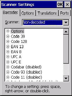
Psion Teklogix Omnii Hand-Held Computer User Manual C-39
Appendix C: Bar Code Settings - TBD
Non-Decoded Scanners
Codablock
Add/Remove Data
Refer to “Add/Remove Data” on page C-12 for details.
C.4.23 Codablock
Enable Codablock A
Set this parameter to on to enable “Codablock type A”.
Enable Codablock F
Set this parameter to on to enable “Codablock type F”.
Length Restriction
Refer to “Length Restriction” on page C-11 for details.
Add/Remove Data
Refer to “Add/Remove Data” on page C-12 for details.
C.5 Non-Decoded Scanners
Figure C.1 Non-Decoded Scanner Options
• Tap on the Scanner drop-down menu, and choose Non-decoded.
All the available bar code symbologies for this type of scanner can be selected in this tab.
A ‘plus’ sign (+) to the left of the menu item indicates that a sub-menu of parameters is
attached.
• Tap on the + sign to display the sub-menu.
C-40 Psion Teklogix Omnii Hand-Held Computer User Manual
Appendix C: Bar Code Settings - TBD
Non-Decoded Scanners
Options
• To change a parameter value, double-tap on the parameter. If you need to type a value, a
dialog box is displayed in which you can type a new value. If you need to change a yes
or no value, double-tapping on the parameter toggles between yes and no.
If you’re using the keyboard:
• Highlight the bar code you want to work with, and press the [RIGHT] arrow key to
display the sub-menu.
• Use the [UP] and [DOWN] arrow keys to highlight a parameter.
• To change a parameter value, press [SPACE] or the [RIGHT] arrow key. If a field
requires text entry, a text box is displayed in which you can enter the appropriate value.
C.5.1 Options
• Tap on the + sign next to Options to display these parameters.
Dot Time (msec)
The value selected for “Dot Time (msec)” determines (in milliseconds) how long the target-
ing dot remains on before the scanner switches to a normal scan sweep. When you double-
tap on this parameter, a dialog box is displayed in which you can enter a value from 0 to
3000. A value of 0 (zero) disables the target dot.
Short Code
When enabled, this parameter allows scanning of short I 2 of 5 bar codes (2 characters).
When disabled, these short bar codes are rejected.
Enabling “Short Code” may reduce the robustness of the decoding since the hand-held must
decode more potential bar codes; it is therefore not recommended for general-purpose bar
codes with 4 or more characters.
Verify
The value entered for this parameter determines the number of correct additional decodes re-
quired after the initial decode, prior to a bar code being accepted. Higher values significantly
increase the time it takes to decode a bar code but also improve the reliability of the decoded
bar code.
Security
This parameter controls the tolerance for decoding edge-to-edge bar codes (Code 93, Code
128, UPC/EAN). Lower values have a lower tolerance for misreads, but they also increase
the time it takes to decode the bar code. The default value of 30 is generally a good compro-
mise setting.

Psion Teklogix Omnii Hand-Held Computer User Manual C-41
Appendix C: Bar Code Settings - TBD
Non-Decoded Scanners
Code 39
C.5.2 Code 39
Enabled
Set this parameter to on to enable “Code 39”.
Full ASCII
If this parameter is enabled, the characters +, %, and / are used as escape characters. The
combination of an escape character and the next character is converted to an equivalent
ASCII character.
Include Check
If this parameter is enabled, the check digit is included with the decoded bar code data.
AIAG Strip
If this parameter is enabled, the AIAG data identifier is removed from each decoded Code
39 label. The data identifier occurs in the first position next to the Code 39 start character. It
can be a single alphabetic character or a series of numeric digits followed by an alphabetic
character. This identifier defines the general category or specific use of the data contained in
the rest of the bar code.
Error Accept
If the “Err Accept” and “AIAG Strip” parameters are enabled, all label data without an
AIAG identifier character is accepted. If the “Err Accept” parameter is disabled and the
“AIAG Strip” parameter is enabled, the label data is not accepted.
MOD Checks
This parameter allows you to choose the check digit calculated: MOD 43 Check, MOD 10
Check or None.
• Double-tap on MOD Checks to display your options.
• Tap on a check digit to highlight it, and tap on OK.
If you choose None, a check is not executed.
Note: If your unit is operating with the Psion Teklogix TESS application, this parameter
should not be used in conjunction with the TESS AIAG feature. This is because the
hand-held performs the strip function before it processes the data through the AIAG
feature; if the prefix is stripped, the data is not identified as AIAG.

C-42 Psion Teklogix Omnii Hand-Held Computer User Manual
Appendix C: Bar Code Settings - TBD
Non-Decoded Scanners
Code 128
Transmit Code ID Char
A code ID character identifies the scanned bar code type. In addition to any single character
prefix already selected, the code ID character is inserted between the prefix and the decoded
symbol.
Length Restriction
Refer to “Length Restriction” on page C-11 for details.
Add/Remove Data
Refer to “Add/Remove Data” on page C-12 for details.
C.5.3 Code 128
Enabled
Set this parameter to on to enable “Code 128”.
Include Sym
Setting “Include Sym” to on causes the group separator(s) and start code contained in this
type of bar code to be displayed on the screen.
Variations
When using Code 128, you can choose the bar code variation the scanner will recognize.
The options available are Standard, UCC 128 and EAN/UCC 128.
• Double-tap on Variations to display a dialog box listing your options.
• Tap on a variation to highlight it, and then tap on OK.
If you choose None, a check is not executed.
Standard
Enable Standard if “Code 128” is desired.
UCC 128
UCC 128 is a variation of “Code 128”.
Note: This option is available only when ‘EAN/UCC 128’ is selected.

Psion Teklogix Omnii Hand-Held Computer User Manual C-43
Appendix C: Bar Code Settings - TBD
Non-Decoded Scanners
EAN 13
EAN/UCC 128
To successfully scan this type of bar code, “EAN/UCC 128” must be enabled. “EAN/UCC”
bar codes include group separators and start codes.
Transmit Code ID Char
A code ID character identifies the scanned bar code type. In addition to any single character
prefix already selected, the code ID character is inserted between the prefix and the decoded
symbol.
Length Restriction
Refer to “Length Restriction” on page C-11 for details.
Add/Remove Data
Refer to “Add/Remove Data” on page C-12 for details.
C.5.4 EAN 13
Enabled
Set this parameter to on to enable “EAN 13”.
Enable Bookland EAN
Setting this parameter to on allows your scanner to recognize Bookland EAN bar codes.
Include Country
If this parameter is enabled, the country code is included with the decoded bar code data.
Include Check
If this parameter is enabled, the check digit is included with the decoded bar code data.
Addendum
An addendum is a separate bar code, supplementary to the main bar code. This parameter
provides three options: Disabled, Optional and Required. Depending on the value chosen for
this parameter, an addendum is recognized or ignored.
• Double-tap on Addendum to display a dialog box listing your options.
Important: Before “Addendum” can take effect, the “Short Code” parameter (see
page C-40) must be enabled.

C-44 Psion Teklogix Omnii Hand-Held Computer User Manual
Appendix C: Bar Code Settings - TBD
Non-Decoded Scanners
EAN 8
• Highlight an item, and tap on OK.
When “Addendum” is set to Disabled the scanner does not recognize an addendum. If this
parameter is set to Optional the scanner searches for an addendum and if one exists, appends
it to the main bar code. When the parameter is set to Required the scanner does not accept
the main bar code without an addendum.
Transmit Code ID Char
A code ID character identifies the scanned bar code type. In addition to any single character
prefix already selected, the code ID character is inserted between the prefix and the decoded
symbol.
Add/Remove Data
Refer to “Add/Remove Data” on page C-12 for details.
C.5.5 EAN 8
Enabled
Set this parameter to on to enable “EAN 8”.
Include Check
If this parameter is enabled, the check digit is included with the decoded bar code data.
Addendum
See “Addendum” on page C-43.
Transmit Code ID Char
A code ID character identifies the scanned bar code type. In addition to any single character
prefix already selected, the code ID character is inserted between the prefix and the decoded
symbol.
Add/Remove Data
Refer to “Add/Remove Data” on page C-12 for details.
Note: Setting Addendum to Optional will reduce performance. This value should only be
used if some bar codes actually have addendums.
Important: Before “Addendum” can take effect, the “Short Code” parameter (see
page C-40) must be enabled.

Psion Teklogix Omnii Hand-Held Computer User Manual C-45
Appendix C: Bar Code Settings - TBD
Non-Decoded Scanners
UPC A
C.5.6 UPC A
Enabled
Set this parameter to on to enable “UPC A”.
Include Number Sys
If this parameter is enabled, the number system digit is included with the decoded bar code
data.
Include Check
If this parameter is enabled, the check digit will be included with the decoded bar code data.
Addendum
Refer to “Addendum” on page C-43.
Transmit Code ID Char
A code ID character identifies the scanned bar code type. In addition to any single character
prefix already selected, the code ID character is inserted between the prefix and the decoded
symbol.
Add/Remove Data
Refer to “Add/Remove Data” on page C-12 for details.
C.5.7 UPC E
Enabled
Set this parameter to on to enable “UPC E”.
Convert to UPC-A
Setting this parameter to on results in a non-standard decoding that returns 12 digits from
the 6 digit UPC E bar code.
Include Number Sys
If this parameter is enabled, the number system digit is included with the decoded bar code
data.
Important: Before “Addendum” can take effect, the “Short Code” parameter (see
page C-40) must be enabled.
Draft 1

C-46 Psion Teklogix Omnii Hand-Held Computer User Manual
Appendix C: Bar Code Settings - TBD
Non-Decoded Scanners
Codabar
Include Check
When enabled, the check digit is included with the decoded bar code data.
Addendum
Refer to “Addendum” on page C-43.
Transmit Code ID Char
A code ID character identifies the scanned bar code type. In addition to any single character
prefix already selected, the code ID character is inserted between the prefix and the decoded
symbol.
Add/Remove Data
Refer to “Add/Remove Data” on page C-12 for details.
C.5.8 Codabar
Enabled
Set this parameter to on to enable “Codabar”.
Strip Start/Stop Chars
Codabar uses the characters A, B, C, and D as start and stop characters. Thus, the first and
last digits of a Codabar message must be A, B, C, or D, and the body of the message should
not contain these characters. Setting this parameter to on strips the start and stop characters
from this bar code.
Transmit Code ID Char
A code ID character identifies the scanned bar code type. In addition to any single character
prefix already selected, the code ID character is inserted between the prefix and the decoded
symbol.
Length Restriction
Refer to “Length Restriction” on page C-11 for details.
Add/Remove Data
Refer to “Add/Remove Data” on page C-12 for details.
Important: Before “Addendum” can take effect, the “Short Code” parameter (see
page C-40) must be enabled.
Draft 1
Psion Teklogix Omnii Hand-Held Computer User Manual C-47
Appendix C: Bar Code Settings - TBD
Non-Decoded Scanners
Code 93
C.5.9 Code 93
Enabled
Set this parameter to on to enable “Code 93”.
Transmit Code ID Char
A code ID character identifies the scanned bar code type. In addition to any single character
prefix already selected, the code ID character is inserted between the prefix and the decoded
symbol.
Length Restriction
Refer to “Length Restriction” on page C-11 for details.
Add/Remove Data
Refer to “Add/Remove Data” on page C-12 for details.
C.5.10 Code 11
Enabled
Set this parameter to on to enable “Code 11”.
Include Check
If “Include Check” is enabled, the check digit is included with the decoded bar code data.
Check Digits
This parameter can be set to None, One Check Digit or Two Check Digits.
• Double-tap on this parameter to display a dialog box listing your options.
• Highlight the check digit you want to use, and tap on OK.
If this parameter set to One Check Digit, it is assumed that the last digit is a check digit.
If this parameter is set to Two Check Digits, it is assumed that the last two digits are check
digits.
Transmit Code ID Char
A code ID character identifies the scanned bar code type. In addition to any single character
prefix already selected, the code ID character is inserted between the prefix and the decoded
symbol.
Draft 1
C-48 Psion Teklogix Omnii Hand-Held Computer User Manual
Appendix C: Bar Code Settings - TBD
Non-Decoded Scanners
Interleaved 2 of 5
Length Restriction
Refer to “Length Restriction” on page C-11 for details.
Add/Remove Data
Refer to “Add/Remove Data” on page C-12 for details.
C.5.11 Interleaved 2 of 5
Enabled
Set this parameter to on to enable “Interleaved 2 of 5”.
MOD 10 Check
If this parameter is enabled, the “MOD 10” check digit is calculated. This calculation is the
same as the Code 39 MOD 10 check digit.
ITF Check
If this parameter is enabled, the ITF-14/16 MOD 10 check digit is calculated.
Include Check
If this parameter is enabled, the check digit is included with the decoded bar code data.
Transmit Code ID Char
A code ID character identifies the scanned bar code type. In addition to any single character
prefix already selected, the code ID character is inserted between the prefix and the decoded
symbol.
Length Restriction
Refer to “Length Restriction” on page C-11 for details.
Add/Remove Data
Refer to “Add/Remove Data” on page C-12 for details.
C.5.12 MSI Plessey
Enabled
Set this parameter to on to enable “MSI Plessey”.
One Check Digit
If this parameter is enabled, it is assumed that the last digit is a check digit.
Draft 1
Psion Teklogix Omnii Hand-Held Computer User Manual C-49
Appendix C: Bar Code Settings - TBD
Non-Decoded Scanners
Discrete 2 of 5
Include Check
If this parameter is enabled, the check digit is included with the decoded bar code data.
Transmit Code ID Char
A code ID character identifies the scanned bar code type. In addition to any single character
prefix already selected, the code ID character is inserted between the prefix and the decoded
symbol.
Length Restriction
Refer to “Length Restriction” on page C-11 for details.
Add/Remove Data
Refer to “Add/Remove Data” on page C-12 for details.
C.5.13 Discrete 2 of 5
Enabled
Set this parameter to on to enable “Discrete 2 of 5”.
MOD 10 Check
If this parameter is enabled, the MOD 10 check digit is calculated. This calculation is the
same as the Code 39 MOD 10 check digit.
ITF Check
If this parameter is enabled, the ITF-14/16 MOD 10 check digit is calculated.
Include Check
If this parameter is enabled, the check digit is included with the decoded bar code data.
Transmit Code ID Char
A code ID character identifies the scanned bar code type. In addition to any single character
prefix already selected, the code ID character is inserted between the prefix and the decoded
symbol.
Length Restriction
Refer to “Length Restriction” on page C-11 for details.
Add/Remove Data
Refer to “Add/Remove Data” on page C-12 for details.
Draft 1
C-50 Psion Teklogix Omnii Hand-Held Computer User Manual
Appendix C: Bar Code Settings - TBD
Non-Decoded Scanners
IATA 2 of 5
C.5.14 IATA 2 of 5
Enabled
Set this parameter to on to enable “IATA 2 of 5”.
MOD 10 Check
If this parameter is enabled, the MOD 10 check digit is calculated.
ITF Check
If this parameter is enabled, the ITF-14/16 MOD 10 check digit is calculated.
Include Check
If this parameter is enabled, the check digit is included with the decoded bar code data.
Transmit Code ID Char
A code ID character identifies the scanned bar code type. In addition to any single character
prefix already selected, the code ID character is inserted between the prefix and the decoded
symbol.
Length Restriction
Refer to “Length Restriction” on page C-11 for details.
Add/Remove Data
Refer to “Add/Remove Data” on page C-12 for details.
Draft 1

Psion Teklogix Omnii Hand-Held Computer User Manual D-1
APPENDIX D
TEKLOGIX IMAGERS APPLET
D.1 Required Applets....................................D-3
D.2 Presets .........................................D-3
D.2.1 Predefined Presets..............................D-4
D.2.2 Bar Code Predefined Presets (Barcoding Tab)................D-4
D.2.2.1 Bar Code Decoding Symbology Predefined Presets........D-4
D.2.2.2 Bar Code Decoding Camera Predefined Presets..........D-5
D.2.3 Image Capture Predefined Presets (Imaging Tab)..............D-5
D.3 Using the Teklogix Imagers Applet ..........................D-6
D.3.1 Configuring the Image Capture Presets (Imaging Tab) ...........D-6
D.3.1.1 Selecting a Camera.........................D-7
D.3.1.2 Setting the Active Preset ......................D-7
D.3.1.3 Viewing a Preset...........................D-7
D.3.1.4 Creating a Custom Preset......................D-8
D.3.1.5 Modifying a Custom Preset.....................D-8
D.3.1.6 Removing a Custom Preset....................D-10
D.3.2 Configuring the Bar Code Decoding Camera Presets (Barcoding Tab) . . D-10
D.3.2.1 Selecting a Camera........................D-11
D.3.2.2 Setting the Active Preset .....................D-11
D.3.2.3 Viewing a Preset..........................D-11
D.3.2.4 Creating a Custom Preset.....................D-11
D.3.2.5 Modifying a Custom Preset....................D-12
D.3.2.6 Removing a Custom Preset....................D-13
D.3.3 Configuring the Bar Code Decoding Symbologies (Barcoding Tab) . . . D-13
D.3.3.1 Setting the Active Preset .....................D-14
D.3.3.2 Viewing a Preset..........................D-14
D.3.3.3 Creating a Custom Preset.....................D-15
D.3.3.4 Modifying a Custom Preset....................D-15
D.3.3.5 Removing a Custom Preset....................D-17
D.3.4 Barcoding Tab – Configuring Symbologies................D-17
D.3.5 Filter Tab – Manipulating Bar Code Data.................D-17
D.3.5.1 Modifying a Bar Code Setting ..................D-18
D.3.6 Translation Tab – Configuring Rules....................D-19
Draft 1
D-2 Psion Teklogix Omnii Hand-Held Computer User Manual
D.3.7 Advanced Tab................................D-20
D.3.7.1 File Locations for Captured Images................D-20
D.3.7.2 Configuring Triggers........................D-21
D.4 Bar Code Symbologies – Descriptions........................D-22
D.4.1 Options ...................................D-22
D.4.2 All 1D With Strong Recovery Enabled ....................23
D.4.3 Code 39...................................D-23
D.4.4 Code 128 ..................................D-24
D.4.5 EAN 13...................................D-24
D.4.6 EAN 8....................................D-24
D.4.7 UPC-A....................................D-25
D.4.8 UPC-E....................................D-25
D.4.9 Code 93...................................D-25
D.4.10 Codabar ..................................D-26
D.4.11 Interleaved 2 of 5..............................D-26
D.4.12 GS1 DataBar................................D-26
D.4.13 2D PDF-417................................D-26
D.4.14 2D Micro PDF-417 ............................D-26
D.4.15 2D Data Matrix...............................D-27
D.4.16 2D QR Code................................D-27
D.4.17 2D Maxicode................................D-27
D.4.18 2D Aztec..................................D-27
D.4.19 Postal: PlaNET...............................D-27
D.4.20 Postal: PostNET..............................D-27
D.4.21 Postal: Australian .............................D-28
D.4.22 Postal: Canadian..............................D-28
D.4.23 Postal: Japanese..............................D-28
D.4.24 Postal: Kix.................................D-28
D.4.25 Postal: Korean...............................D-28
D.4.26 Postal: Royal................................D-28
Draft 1

Appendix D: Teklogix Imagers Applet
Required Applets
Psion Teklogix Omnii Hand-Held Computer User Manual D-3
The Teklogix Imagers applet is used to create, modify, delete, and activate imager settings.
The principal uses of the application are to decode bar codes and to capture images. This
imager services application is used for cameras and imagers to configure linear (1D),
stacked linear, matrix (true 2D) and postal bar codes. A Demonstration Application is pro-
vided to demonstrate how the imager works. Refer to “Demo” on page 71 for details.
D.1 Required Applets
In order to configure imaging, the Manage Triggers applet must be present in the Control
Panel, along with the Teklogix Imagers applet.
D.2 Presets
There are two methods that can be used to configure an imager using the Teklogix Imagers
applet:
• Use a predefined preset.
• Create a custom preset based on a predefined preset.
A preset is a group of exposure and image correction settings. Each preset configures the
imager for a specific purpose such as bar code decoding or image capture.
Presets also allow easier and faster configuration of the imager after power-on or resume
from suspend.
The predefined presets are generic and satisfy most user requirements. A custom preset can
be created for a specific user application, such as: include only specified bar codes, read
only a specified number of bar codes or for reading unusual media.
Every preset belongs to a preset type. The following preset types are available:
Note: The Teklogix Imagers icon is only displayed when the appropriate imager is
installed in your Omnii. If there is an imager installed but this icon is not present,
additional software (ICS) may need to be installed.
To enable a newly-installed imager, press and hold down the [FN] key and the
[ENTER/Power] key simultaneously for a minimum of three seconds.
Important: It is strongly recommended that a predefined preset is used
whenever possible. Each predefined preset contains a coherent
group of settings that are known to work together in the intended
environment. In almost all situations, at least one of the prede-
fined presets results in a satisfactory outcome.
Draft 1

D-4 Psion Teklogix Omnii Hand-Held Computer User Manual
Appendix D: Teklogix Imagers Applet
Predefined Presets
• Imaging for photo capture.
• Imaging for bar code decoding.
• Symbology selection.
At any time, only one preset of each type can be designated as the user-selected
active preset.
D.2.1 Predefined Presets
Predefined presets are built into the imaging software and cannot be changed. The pre-
defined presets allow you to use the imager to perform specified tasks without having to
understand and set numerous variables. In almost all cases these predefined presets
are sufficient.
D.2.2 Bar Code Predefined Presets (Barcoding Tab)
These presets encompass the majority of the most popular bar codes and their subtypes. The
bar code decoding symbology predefined presets define which bar codes can be decoded.
The bar code decoding camera predefined presets determine how the bar code images
are captured.
D.2.2.1 Bar Code Decoding Symbology Predefined Presets
The following presets select groups of similar bar codes for decoding.
My Default
This preset uses the Symbology Settings menu to define the preset. For details about the
Symbology Settings menu, refer to “Barcoding Tab – Configuring Symbologies” on page D-
17.
Factory Default
This preset enables the decoding of frequently used bar codes.
All
This preset enables the decoding of all bar codes that the imager can decode.
Linear
This preset enables the decoding of all the 1D symbologies that the imager can decode.
Note: It is recommended that the default preset be used whenever possible.
Draft 1

Appendix D: Teklogix Imagers Applet
Image Capture Predefined Presets (Imaging Tab)
Psion Teklogix Omnii Hand-Held Computer User Manual D-5
Linear and PDF417
This preset enables the decoding of all the 1D and PDF symbologies that the imager can
decode.
Matrix
This preset enables the decoding of all 2D symbologies that the imager can decode.
Postal
This preset enables the decoding of all the postal symbologies that the imager can decode.
D.2.2.2 Bar Code Decoding Camera Predefined Presets
The following presets enable successful bar code image capture in almost all conditions.
Default
This preset works in a wide range of conditions. It is optimized for a normal office lighting
(about 300 Lux).
Low Light
This preset is designed for very dark conditions such as inside a warehouse where the lights
are kept low, or inside an unlit truck. This preset increases either the exposure time or the
gain.
Low Power
This preset minimizes the use of the flash so as to conserve the battery power on the hand-
held.
Glossy Surface
This preset minimizes the use of the flash so as to reduce reflection. This preset is used to
read bar codes that are behind glass, or inside the plastic window of an envelope.
D.2.3 Image Capture Predefined Presets (Imaging Tab)
The following presets enable successful image capture in almost all conditions.
Note: It is recommended that the default preset be used whenever possible.
Note: It is recommended that the default preset be used whenever possible.
Draft 1

D-6 Psion Teklogix Omnii Hand-Held Computer User Manual
Appendix D: Teklogix Imagers Applet
Using the Teklogix Imagers Applet
Default
This preset works in a wide range of conditions. It is optimized for a normal office lighting
(about 300 Lux).
Motion
This preset uses a shorter exposure time so as to freeze motion.
Low Light Near
This preset is designed for dark conditions, it uses a longer exposure time and includes
the flash.
D.3 Using the Teklogix Imagers Applet
D.3.1 Configuring the Image Capture Presets (Imaging Tab)
To configure the image capture presets, open the dialog box as follows:
• Tap on Start>Settings>Control Panel.
• Tap on the Teklogix Imagers icon, and if it’s not already selected, tap on the
Imaging tab.
The following screen is displayed.
Draft 1
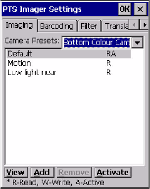
Appendix D: Teklogix Imagers Applet
Configuring the Image Capture Presets (Imaging Tab)
Psion Teklogix Omnii Hand-Held Computer User Manual D-7
Figure D.1 Imaging Tab
This window lists all the presets, both predefined and custom. Presets are identified
as follows:
• Predefined presets are marked as ‘R’ read-only.
• Custom presets are marked as ‘RW’ read and write.
• One preset—either predefined or custom—is marked as ‘A’ active.
D.3.1.1 Selecting a Camera
To select a camera:
• Tap on the Camera Presets drop-down menu to view the camera options.
• Choose a camera—specifically, Front Imager which is located at the top of the unit.
D.3.1.2 Setting the Active Preset
An active preset has an A to the right. To set an active preset:
• Highlight the preset, and tap on the Activate button.
D.3.1.3 Viewing a Preset
To view the parameter settings in a preset:
• Highlight a preset, and double-tap on the View button.
The associated preset window is displayed.
Draft 1
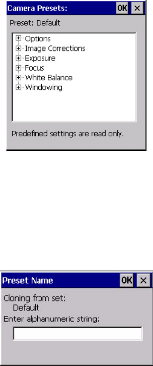
D-8 Psion Teklogix Omnii Hand-Held Computer User Manual
Appendix D: Teklogix Imagers Applet
Configuring the Image Capture Presets (Imaging Tab)
• Tap on the + sign to expand the lists so that you can view the parameter settings.
D.3.1.4 Creating a Custom Preset
A new custom preset is created by modifying a preset—either a predefined preset or an ex-
isting custom preset. To create a custom preset:
• Highlight a preset, and tap on the Add button.
A screen like the sample below is displayed.
• Type the name of the new preset in the dialog box.
• Tap on OK to save your changes.
The preset list is displayed; the new custom preset appears at the end of the list. It is marked
as read and write.
D.3.1.5 Modifying a Custom Preset
The parameter values in a custom preset can be modified. It is recommended that very few
changes be made to a custom preset. To ensure that it will work reliably, it should be as close
as possible to the original predefined preset. To change a parameter value:
Draft 1
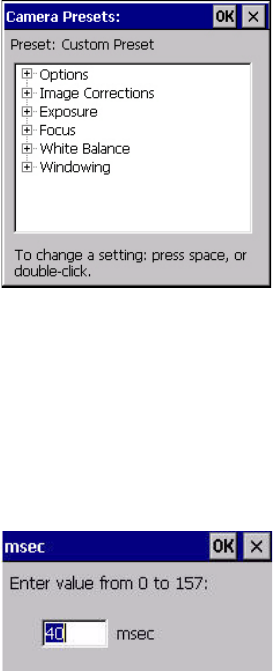
Appendix D: Teklogix Imagers Applet
Configuring the Image Capture Presets (Imaging Tab)
Psion Teklogix Omnii Hand-Held Computer User Manual D-9
• Highlight the custom preset, and double-tap on the Edit button.
• Tap on the + symbols to expand the lists so that you can view the parameter settings.
• Scroll through the parameter list until you reach the parameter that you want to change.
• For a parameter that can take a range of values:
- Highlight the parameter, and then press the [SPACE] key or double-click on
the parameter.
- An associated dialog box containing the valid range of values for the parameter and
the current setting like the sample screen following is displayed.
- Type a value in the field provided.
• For a parameter that toggles between two values such as on or off and enabled
or disabled:
- Highlight the parameter and then press the [SPACE] key, or double-click on the
parameter. Either method toggles between the two available values.
• When you’ve completed your edits, tap on OK.
The parameter list is displayed; the new value for the changed parameter is shown.
• Tap on OK to exit to the preset list and save the changes.
Draft 1

D-10 Psion Teklogix Omnii Hand-Held Computer User Manual
Appendix D: Teklogix Imagers Applet
Configuring the Bar Code Decoding Camera Presets (Barcoding Tab)
D.3.1.6 Removing a Custom Preset
• Highlight the custom preset you want to delete, and tap on the Remove button.
A window is displayed warning you that you are about to remove a preset.
• Tap on Ye s to remove the preset or No to cancel the operation.
D.3.2 Configuring the Bar Code Decoding Camera Presets (Barcoding Tab)
To configure the bar code decoding camera presets:
• Tap on Start>Settings>Control Panel>Teklogix Imagers.
• Tap on the Barcoding tab.
Figure D.2 Camera Presets
This window lists all the presets, both predefined and the custom. Presets are identified
as follows:
• Predefined presets are marked as read-only. For a description, review “Predefined Pre-
sets” on page D-4.
• Predefined presets are marked as ‘R’ read-only.
• Custom presets are marked as ‘RW’ read and write.
• One preset—either predefined or custom—is marked as ‘A’ active.
Note: The top portion of the window displays the bar code decoding camera presets.
Draft 1
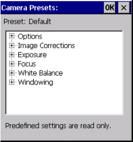
Appendix D: Teklogix Imagers Applet
Configuring the Bar Code Decoding Camera Presets (Barcoding Tab)
Psion Teklogix Omnii Hand-Held Computer User Manual D-11
D.3.2.1 Selecting a Camera
To select a camera:
• Tap on the Camera Presets drop-down menu to view the camera options.
• Choose a camera—specifically, Front Imager which is located at the top of the unit.
D.3.2.2 Setting the Active Preset
An active preset has an A to the right; in Figure D.3 on page 14, the active preset is Default.
To set an active preset:
• Highlight the preset, and tap on the Activate button.
D.3.2.3 Viewing a Preset
To view the parameter settings in a preset:
• Highlight a preset, and double-tap on the View button.
The associated preset window is displayed.
• Tap on the + sign to expand one of the lists so that you can view the parameter settings.
D.3.2.4 Creating a Custom Preset
A new custom preset is created by modifying a preset—either a predefined preset or an ex-
isting custom preset. To create a custom preset:
• Highlight a preset, and tap on the Add button.
A screen like the sample following is displayed.
Draft 1
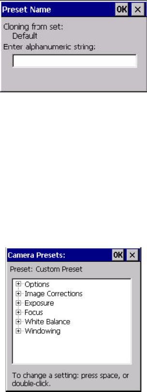
D-12 Psion Teklogix Omnii Hand-Held Computer User Manual
Appendix D: Teklogix Imagers Applet
Configuring the Bar Code Decoding Camera Presets (Barcoding Tab)
• Type the name of the new preset in the dialog box.
• Tap on OK to save your changes.
The preset list is displayed; the new custom preset appears at the end of the list. It is marked
as read and write.
D.3.2.5 Modifying a Custom Preset
The parameter values in a custom preset can be modified. It is recommended that very few
changes be made to a custom preset. To ensure that it will work reliably, it should be as close
as possible to the original predefined preset. To change a parameter value:
• Highlight the custom preset, and double-tap on the Edit button.
• Tap on the + symbols to expand the lists and view the parameter settings.
• Scroll through the parameter list until you reach the parameter that you want to change.
• For a parameter that can take a range of values:
- Highlight the parameter, and then press the [SPACE] key or double-click the
parameter.
Draft 1
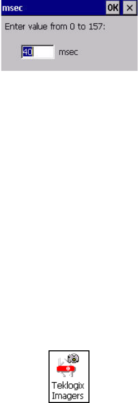
Appendix D: Teklogix Imagers Applet
Configuring the Bar Code Decoding Symbologies (Barcoding Tab)
Psion Teklogix Omnii Hand-Held Computer User Manual D-13
- An associated dialog box containing the valid range of values for the parameter and
the current setting like the sample screen following is displayed.
- Type a value in the field provided.
• For a parameter that toggles between two values such as on or off and enabled or
disabled:
- Highlight the parameter and then press the [SPACE] key, or double-click on the
parameter. Either method toggles between the two available values.
• When you’ve completed your edits, tap on OK.
The parameter list is displayed; the new value for the changed parameter is shown.
• Tap on OK to exit to the preset list and save the changes.
D.3.2.6 Removing a Custom Preset
• Highlight the custom preset you want to delete, and tap on the Remove button.
A window is displayed warning you that you are about to remove a preset.
• Tap on Ye s to remove the preset or No to cancel the operation.
D.3.3 Configuring the Bar Code Decoding Symbologies (Barcoding Tab)
To configure the bar code decoding camera presets:
• Tap on Start>Settings>Control Panel>Teklogix Imagers.
• Tap on the Barcoding tab.
Draft 1
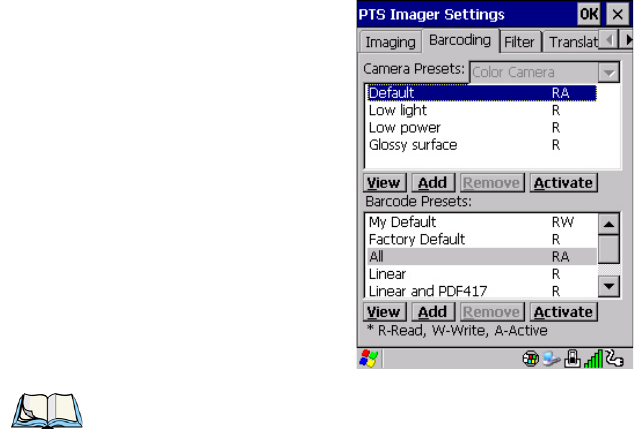
D-14 Psion Teklogix Omnii Hand-Held Computer User Manual
Appendix D: Teklogix Imagers Applet
Configuring the Bar Code Decoding Symbologies (Barcoding Tab)
Figure D.3 Viewing Bar Code Decoding Symbologies
D.3.3.1 Setting the Active Preset
An active preset has an A to the right; in Figure D.3 on page 14, the active preset is Default.
To set an active preset:
• Highlight the preset, and tap on the Activate button.
D.3.3.2 Viewing a Preset
To view the parameter settings in a preset:
• Highlight a preset, and double-tap on the View button.
The associated preset window is displayed.
Note: The bottom portion of the window displays the bar code decoding bar code
presets.
Draft 1
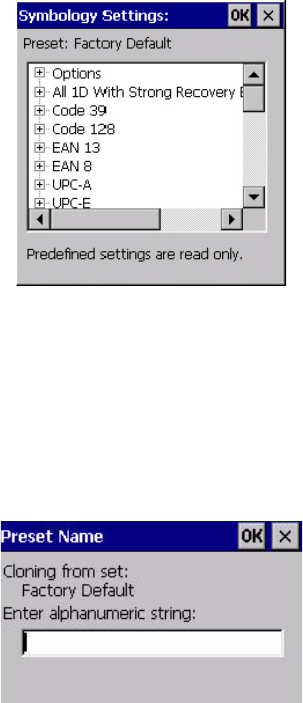
Appendix D: Teklogix Imagers Applet
Configuring the Bar Code Decoding Symbologies (Barcoding Tab)
Psion Teklogix Omnii Hand-Held Computer User Manual D-15
• Tap on the + sign to expand one of the lists so that you can view the parameter settings.
D.3.3.3 Creating a Custom Preset
A new custom preset is created by modifying a preset—either a predefined preset or an ex-
isting custom preset. To create a custom preset:
• Highlight a preset, and tap on the Add button.
A screen like the sample following is displayed.
• Type the name of the new preset in the dialog box.
• Tap on OK to save your changes.
The preset list is displayed; the new custom preset appears at the end of the list. It is marked
as read and write.
D.3.3.4 Modifying a Custom Preset
The parameter values in a custom preset can be modified. It is recommended that very few
changes be made to a custom preset. To ensure that it will work reliably, it should be as close
as possible to the original predefined preset. To change a parameter value:
Draft 1
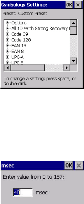
D-16 Psion Teklogix Omnii Hand-Held Computer User Manual
Appendix D: Teklogix Imagers Applet
Configuring the Bar Code Decoding Symbologies (Barcoding Tab)
• Highlight the custom preset, and double-tap on the Edit button.
• Tap on the + symbols to expand the lists and view the parameter settings.
• Scroll through the parameter list until you reach the parameter that you want to change.
• For a parameter that can take a range of values:
- Highlight the parameter, and then press the [SPACE] key or double-click the
parameter.
- An associated dialog box containing the valid range of values for the parameter and
the current setting like the sample screen following is displayed.
- Type a value in the field provided.
• For a parameter that toggles between two values such as on or off and enabled or
disabled:
- Highlight the parameter and then press the [SPACE] key, or double-click on the
parameter. Either method toggles between the two available values.
• When you’ve completed your edits, tap on OK.
The parameter list is displayed; the new value for the changed parameter is shown.
• Tap on OK to exit to the preset list and save the changes.
Draft 1

Appendix D: Teklogix Imagers Applet
Barcoding Tab – Configuring Symbologies
Psion Teklogix Omnii Hand-Held Computer User Manual D-17
D.3.3.5 Removing a Custom Preset
• Highlight the custom preset you want to delete, and tap on the Remove button.
A window is displayed warning you that you are about to remove a preset.
• Tap on Ye s to remove the preset or No to cancel the operation.
D.3.4 Barcoding Tab – Configuring Symbologies
To view the Symbology Settings options:
• Tap on the Barcoding tab, highlight All and then double-tap the View button.
To edit a default preset, you must first activate it:
• Tap on My Default, and tap on the Activate button – an A appears to the right of
My Default.
Once the preset is activated, you can enable or disable the bar codes the imager will read.
• Highlight My Default in the Barcoding tab.
• Double-tap on the Edit button.
None of the other bar code decoding predefined presets are changed.
D.3.4.1 Symbology Settings
D.3.5 Filter Tab – Manipulating Bar Code Data
To configure rules for manipulating bar code data:
• Tap on Start>Settings>Control Panel.
• Tap on the Teklogix Imagers icon, and then tap on the Filter tab.
Note: For descriptions of the bar code symbologies, review “Bar Code Symbologies –
Descriptions” on page D-22.
Draft 1
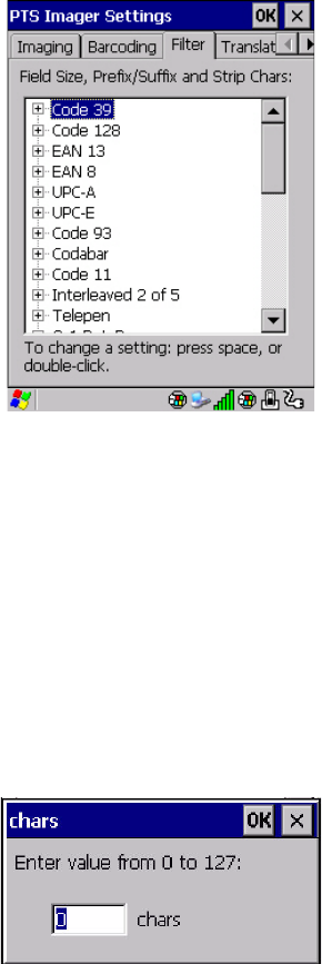
D-18 Psion Teklogix Omnii Hand-Held Computer User Manual
Appendix D: Teklogix Imagers Applet
Filter Tab – Manipulating Bar Code Data
D.3.5.1 Modifying a Bar Code Setting
The rules for manipulating data from selected bar code symbologies can be modified. To
change the settings for a symbology:
• Tap on the + symbols to expand the lists and view the parameter settings.
• Scroll through the parameter list until you reach the parameter that you want to change.
• For a parameter that can take a range of values:
- Highlight the parameter, and then press the [SPACE] key or double-click the
parameter.
- An associated dialog box containing the valid range of values for the parameter and
the current setting like the sample screen following is displayed.
- Type a value in the field provided.
• For a parameter that takes a single character:
- Highlight the parameter and then press the [SPACE] key, or double-click the parame-
ter. The following screen is displayed:
Draft 1
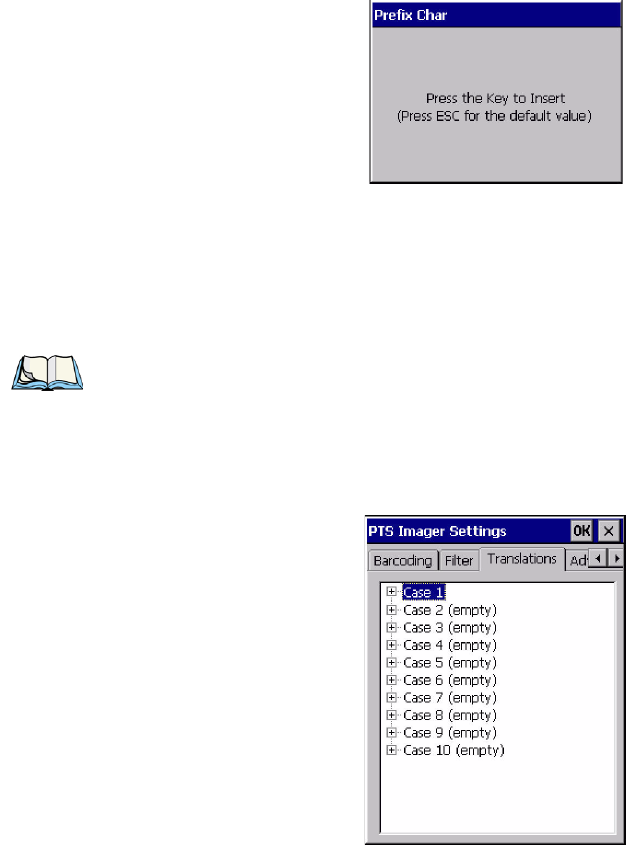
Appendix D: Teklogix Imagers Applet
Tr a n s l a t i o n Ta b – C o n f i g u r in g Ru l e s
Psion Teklogix Omnii Hand-Held Computer User Manual D-19
• When you’ve completed your edits, tap on OK.
D.3.6 Translation Tab – Configuring Rules
Translation rules enable the automatic processing of bar code data. Up to 10 cases can be de-
fined, each consisting of up to 10 sequential rules.
• Tap on Start>Settings>Control Panel.
• Tap on the Teklogix Imagers icon, and then tap on the Translations tab.
For instructions on adding, editing, and removing translation rules, refer to “Translations
Tab” on page 164.
Note: Changes made to the translations configuration using the Teklogix Scanner Con-
trol Panel program are synchronized with changes made here. Changes made in
either place affect both translation tables.
Draft 1
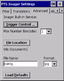
D-20 Psion Teklogix Omnii Hand-Held Computer User Manual
Appendix D: Teklogix Imagers Applet
Advanced Tab
D.3.7 Advanced Tab
D.3.7.1 File Locations for Captured Images
To configure the location for saved images, open the dialog box as follows:
• Tap on Start>Settings>Control Panel.
• Tap on the Teklogix Imagers icon, and then tap on the Advanced tab.
To define the location where imager files will be stored:
• Tap on the File Location button.
Draft 1
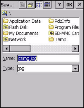
Appendix D: Teklogix Imagers Applet
Advanced Tab
Psion Teklogix Omnii Hand-Held Computer User Manual D-21
• Type the file Name, choose the Folder and file Type.
• Choose the Location in which your files will be saved.
• When you have completed all the changes, tap on the Save button.
D.3.7.2 Configuring Triggers
Viewing the Trigger Configuration
The trigger on Omnii is configured using the Manage Triggers applet. The Teklogix Imagers
applet provides a shortcut to the Manage Triggers applet.
•In the Advanced tab, tap on the Trigger Control button.
• To view all the triggers and the hardware devices that are configured to use them, tap in
the checkbox next to Show all modules.
Draft 1
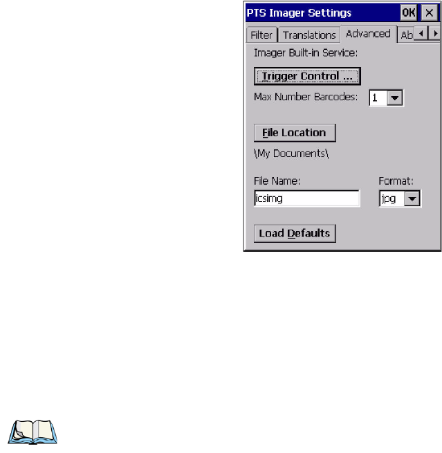
D-22 Psion Teklogix Omnii Hand-Held Computer User Manual
Appendix D: Teklogix Imagers Applet
Bar Code Symbologies – Descriptions
Adding, Editing and Removing Triggers
For instruction about adding, editing and removing triggers, refer to “Manage Triggers” on
page 111.
D.4 Bar Code Symbologies – Descriptions
To view all symbologies available for the imager:
• Tap on the Barcoding tab, highlight All, and then double-tap the View button.
D.4.1 Options
Auto Retry On Failed Decode Enabled
Setting this parameter to on allows the imager to repeat the image capture attempt if the
initial attempt fails. The number of retries is dependent on the value assigned in the next pa-
rameter, Max Number of Auto Retry. If this parameter is set to off, the imager will only
attempt the image capture once.
Note: Remember that if you want to edit the symbologies, the preset you want to
change must be active. Highlight the preset you want to edit, and tap on the
Activate button – an A is added at the far right of the preset. With the activated
preset highlighted, double-tap on the Edit button.
Draft 1
Appendix D: Teklogix Imagers Applet
All 1D With Strong Recovery Enabled
Psion Teklogix Omnii Hand-Held Computer User Manual D-23
Max Number of Auto Retry
The value assigned for this parameter governs the number of times the imager will attempt
to capture a bar code if the first attempt fails to a maximum of 99 times.
Decoder Timeout
This parameter determines the maximum time that the decoder will spend searching for
barcode on captured image. The value assigned here is dependent on the type of bar code
and quality of the image being capture. For example, the value may need to be increased to
compensate for larger bar codes with more data encoded or for poor quality images. On the
other hand, the value can be decreased for smaller, good quality images. The allowable
value ranges from 200 to 500 msec.
Perspective Pattern Enabled - TBD
Document perspective correction manipulates a captured image—usually a document—so
that it appears that the camera was perpendicular to the image plane, when in fact the image
was distorted because the camera was at an angle to the image plane. After perspective cor-
rection all lines that are parallel on the original, are parallel on the image, and the image is
displayed as it appears on the original page. When this parameter is enabled,
Single Target Mode Enabled
When this parameter is enabled, the decoder assumes that a single bar code exists in the
image and that it is located in the centre of the image.
Add AIM ID Prefix
The AIM ID (Association for Automatic Identification and Mobility) is an international bar
code identifier. When this parameter is enabled, the AIM ID is inserted at the beginning of
the decoded bar code.
D.4.2 All 1D With Strong Recovery Enabled
Enabled
Setting this parameter to on.
D.4.3 Code 39
Enabled
Setting this parameter to on makes “Code 39” readable to the imager.
Draft 1
D-24 Psion Teklogix Omnii Hand-Held Computer User Manual
Appendix D: Teklogix Imagers Applet
Code 128
Full ASCII Enabled
If this parameter is enabled, the characters +, %, and / are used as escape characters. The
combination of an escape character and the next character is converted to an equivalent
ASCII character.
Check Char
When this parameter is enabled, before data is output, the “Code 39” symbol integrity is ver-
ified based on a parity character that must be present in the code. If the parity character is not
part of the code, the code is not output. Keep in mind the parity character may not be part of
your output setup; in this case, this parameter should be turned off.
Check Char Strip
If this parameter is set to on, check characters – if present – are not output.
D.4.4 Code 128
Enabled
Set this parameter to on to enable “Code 128”.
D.4.5 EAN 13
Enabled
Set this parameter to on to enable “EAN 13”.
Supplements 2 and Supplements 5
Supplements are additions to EAN/UPC codes. These addendums can be 2 or 5 characters in
length. Usually, data from an addendum is a suffix to the main symbol output data.
Mandatory Enabled
When this parameter is set to on, the imager does not accept the main bar code without a
supplement.
D.4.6 EAN 8
Enabled
Set this parameter to on to enable “EAN 8”.
Draft 1
Psion Teklogix Omnii Hand-Held Computer User Manual D-25
Appendix D: Teklogix Imagers Applet
Bar Code Symbologies – Descriptions
UPC-A
Supplements 2 and Supplements 5
Supplements are additions to EAN/UPC codes. These addendums can be 2 or 5 characters in
length. Usually, data from an addendum is a suffix to the main symbol output data.
Mandatory Enabled
When this parameter is set to on, the imager does not accept the main bar code without a
supplement.
D.4.7 UPC-A
Enabled
Set this parameter to on to enable “UPC-A”.
Supplements 2 and Supplements 5
Supplements are additions to EAN/UPC codes. These addendums can be 2 or 5 characters in
length. Usually, data from an addendum is a suffix to the main symbol output data.
Mandatory Enabled
When this parameter is set to on, the imager does not accept the main bar code without a
supplement.
D.4.8 UPC-E
Enabled
Set this parameter to on to enable “UPC E”.
Supplements 2 and Supplements 5
Supplements are additions to EAN/UPC codes. These addendums can be 2 or 5 characters in
length. Usually, data from an addendum is a suffix to the main symbol output data.
Mandatory Enabled
When this parameter is set to on, the imager does not accept the main bar code without a
supplement.
D.4.9 Code 93
Enabled
Set this parameter to on to enable “Code 93”.
Draft 1
D-26 Psion Teklogix Omnii Hand-Held Computer User Manual
Appendix D: Teklogix Imagers Applet
Bar Code Symbologies – Descriptions
Codabar
D.4.10 Codabar
Enabled
Set this parameter to on to enable “Codabar”.
D.4.11 Interleaved 2 of 5
Enabled
Set this parameter to on to enable “Interleaved 2 of 5”.
Check Char
When this parameter is set to on, the integrity of a “Interleaved 2 of 5” symbol is checked to
ensure that it complies with specified algorithms.
Check Char Strip
If you enable this parameter, a check character is stripped from the decoded bar code data.
D.4.12 GS1 DataBar
GS1 DataBar
Set this parameter to on to enable the imager to read “GS1 Databar” symbols.
Minimum and Maximum Length
The length of a code refers to the number of characters (i.e., human readable characters), in-
cluding check digit(s). Double-tapping on these parameters displays a screen in which you
can set the minimum and maximum allowable code lengths – 4 to 74.
D.4.13 2D PDF-417
Enabled
Set this parameter to on to enable “2D PDF-417”.
D.4.14 2D Micro PDF-417
Enabled
Set this parameter to on to enable “2D Micro PDF-417”.
Draft 1
Psion Teklogix Omnii Hand-Held Computer User Manual D-27
Appendix D: Teklogix Imagers Applet
Bar Code Symbologies – Descriptions
2D Data Matrix
D.4.15 2D Data Matrix
Enable
Set this parameter to on to enable “2D Data Matrix”.
Inverse Enabled
TBD
Rectangular Enabled
TBD
D.4.16 2D QR Code
Enabled
Set this parameter to on to enable “2D QR Code”.
D.4.17 2D Maxicode
Enabled
Set this parameter to on to enable “2D Maxicode”.
D.4.18 2D Aztec
Enabled
Set this parameter to on to enable “2D Aztec”.
D.4.19 Postal: PlaNET
Enabled
Set this parameter to on to enable “Postal: PlaNET”.
D.4.20 Postal: PostNET
Enabled
Set this parameter to on to enable “Postal: PostNET”.
Draft 1
D-28 Psion Teklogix Omnii Hand-Held Computer User Manual
Appendix D: Teklogix Imagers Applet
Bar Code Symbologies – Descriptions
Postal: Australian
D.4.21 Postal: Australian
Enabled
Set this parameter to on to enable “Postal: Australian”.
D.4.22 Postal: Canadian
Enabled
Set this parameter to on to enable “Postal: Canadian”.
D.4.23 Postal: Japanese
Enabled
Set this parameter to on to enable “Postal: Japanese”.
D.4.24 Postal: Kix
Enabled
Set this parameter to on to enable “Postal: Kix”.
D.4.25 Postal: Korean
Enabled
Set this parameter to on to enable “Postal: Korean”.
D.4.26 Postal: Royal
Enabled
Set this parameter to on to enable “Postal: Royal”.
Draft 1
Draft 1