Psion 8516 8516 Vehicle Mount Computer User Manual 8516 Vehicle Mount Computer
Psion Inc 8516 Vehicle Mount Computer 8516 Vehicle Mount Computer
Psion >
Contents
- 1. User Manual 1
- 2. User Manual 2
- 3. User Manual 3
User Manual 3
Chapter 4: Configuration
Ports
Psion 8516 Vehicle-Mount Computer User Manual
90
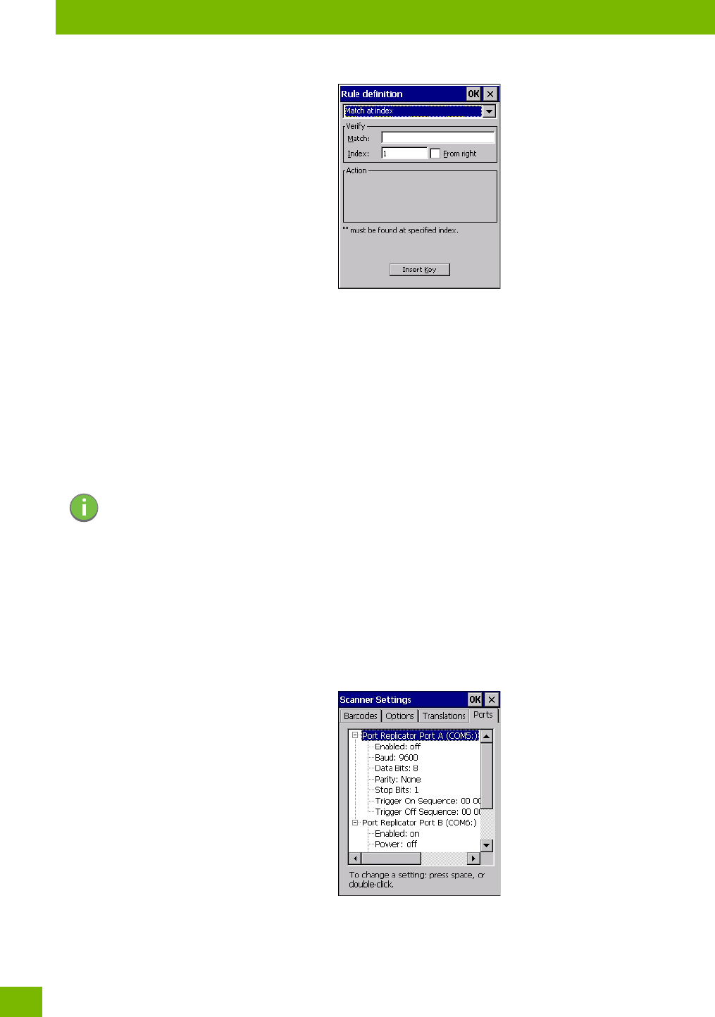
When you choose a rule, an associated screen is displayed in which you can define the rule.
4.20.3.1 Case Rules
The case rules are defined as follows:
•No rule — ignored.
•Search and replace — replaces all instances of the match string. (Note that this rule cannot fail.)
•Match at index — matches the match string at a specified index.
•Match and replace at index — matches the match string at a specified index and replaces/changes it.
•Replace at index — replaces/changes unspecified data in a given range.
•Add barcode prefix/suffix — adds a global prefix or suffix.
•Verify barcode size — verifies the barcode size. This rule should generally be assigned first, before cre-
ating subsequent rules.
Translation information about the status of each case/rule is displayed in the scan log file (see “Scan Log
File” on page 88) when enabled. This is useful if a case fails, and you are trying to determine why a rule
is failing.
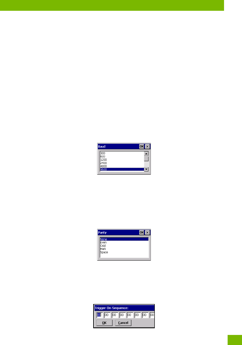
4.20.4 Ports
Figure 4.5 Console and Port Replicator Port Settings
While you cannot configure the scanner, you can configure communications with a serial decoded scanner
using the options in this tab.
Use these settings to ensure that the communication ports on the 8516 match the settings of the serial
devices to which they are connected. If the settings do not match exactly, the devices may not function.
Note: Keep in mind that the effects of previously applied rules must be taken into account when
creating subsequent rules. For example, if the barcode size is important, it should be
checked before any rules that might change the size are applied.
Chapter 4: Configuration
Ports
91
Psion 8516 Vehicle-Mount Computer User Manual
Note that some devices can auto-detect serial port settings (such as baud rate), and in this case the 8516
will dictate the settings. Baud rates often have a direct impact on performance—they should be set as high
as possible while still ensuring reliable communication.
4.20.4.1 Port Replicator Port A (COM5) and Port B (COM6)
Port Replicator Port A (COM5) and Port B (COM6) are standard RS-232 DE-9 DTE ports on the 8516 port
replicator module, available on some snap modules and cradle types.
Enabled
This parameter must be set to ON in order for the 8516 to recognize the device connected to the Port Rep-
licator 9-pin (COM5).
Power (COM6 only)
Pin 9 on the 8516 COM6 is reserved for 5V power out and is defaulted to OFF. This parameter must be set to
ON to enable power to a Snap Module or Vehicle cradle.
Baud
Double-tapping on this parameter displays a pop-up window in which you can choose an appropriate rate of
data transfer.
Figure 4.6 Port Baud Rates
Data Bits
This parameter determines the number of data bits included in each asynchronous data byte. Most devices
use 8-bit data bytes. Double-tapping on this option displays a pop-up window in which you can choose
either 7 or 8 data bits.
Parity
This parameter determines the type of parity checking used on the data going through the port replicator
port. Double-tapping on this option displays a pop-up window in which you can choose the appropriate
parity.
Stop Bits
This parameter specifies the number of stop bits—1, 1.5 or 2—used for asynchronous communication.
Trigger On Sequence And Trigger Off Sequence
If a SICK scanner connected to an 8516 port requires a serial stream of data bytes to trigger the scanner on
and another to trigger the scanner off, the Trigger On Sequence and Trigger Off Sequence parameters
allow you to define these serial streams.
Chapter 4: Configuration
Storage Manager
Psion 8516 Vehicle-Mount Computer User Manual
92
Double-tapping on Trigger On Sequence or Trigger Off Sequence displays a screen with a hex array of 10 el-
ements.
These parameters work in conjunction with Manage Triggers sending on and off data streams to the trigger
module you assigned. For example, suppose you launch Manage Triggers and choose Decoded Scanner as
the ‘module to trigger’. Next, you assign a ‘trigger key’—for this example, . (period). To define the serial
stream of data bytes to control the on and off function of the ‘trigger key’, enter a hex value in the Trigger
On Sequence and the Trigger Off Sequence fields. When you press the trigger key, the Trigger On Sequence
is sent and when you release the trigger key, the Trigger Off Sequence is sent, turning the trigger key on
and off.
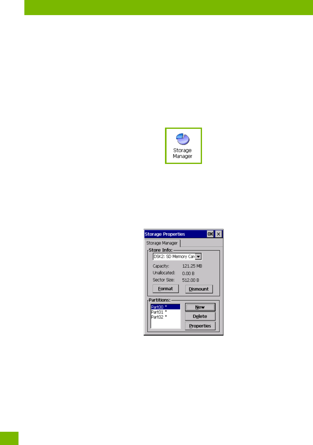
4.21 Storage Manager
The Storage Manager allows you to view information about the storage devices that are present in the
8516, such as SD-MMC flash cards and Compact Flash cards.
4.21.1 Formatting a Memory Card
Formatting a memory card bulk-erases it. Once a card is erased, partitions may be created in it, similarly to
those on a hard drive. Memory-card devices are normally ‘mounted’ (made available to the system) auto-
matically when they are inserted. They must be dismounted before they can be formatted.
To format an entire memory card:
1. Select Start> Settings>Control Panel.
2. In Control Panel, double-click on the Storage Manager icon. The Storage Manager menu opens:
1. Select the memory card from the drop-down list.
2. Press the Dismount button to dismount the memory card. All partitions on the card will be
dismounted.
3. Press the Format button to format the memory card.
All partitions and information on the card will be erased during the formatting process.
4.21.2 Creating Partitions
Once the card is formatted, new partitions can be created in it. The default is to create one partition that
occupies the whole card, but a card can be divided into more than one partition if desired. Each partition
appears as a separate folder in Windows Explorer.
To create new partitions:
Chapter 4: Configuration
Partition Management
93
Psion 8516 Vehicle-Mount Computer User Manual
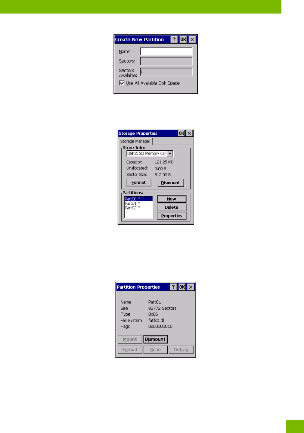
1. Press the New button next to the Partitions list box. The Create New Partition dialog box appears:
1. Type a name for the partition.
2. If more than one partition is desired, uncheck the Use All Available Diskspace checkbox, then
specify the desired number of sectors to be used by the partition.
1. Press OK. The new partition appears in the Partitions list.
The new partition is automatically mounted. This is indicated by an asterisk (*) next to its name in the parti-
tion list. Any unallocated space on the card is indicated at the left, and additional partitions can be created
in it.
4.21.3 Partition Management
Partitions can be individually dismounted, mounted, deleted, or formatted as well. These and additional
tasks are available from the Partition Properties dialog:
To dismount a partition:
1. Choose the desired partition.
2. Tap the Properties button. The Partition Properties dialog appears.
3. Tap the Dismount button. The partition is dismounted. The asterisk disappears next to its name in
the partitions list.
To delete a partition:
1. Select the desired partition.
Chapter 4: Configuration
Partition Management
Psion 8516 Vehicle-Mount Computer User Manual
94
2. Tap the Delete button. A warning dialog appears.
3. Tap the OK button. The partition is deleted.
To format a partition:
1. Choose the desired partition.
2. Tap the Properties button. The Partition Properties dialog appears.
3. Tap the Dismount button. The partition is dismounted. The asterisk disappears next to its name in
the partitions list.
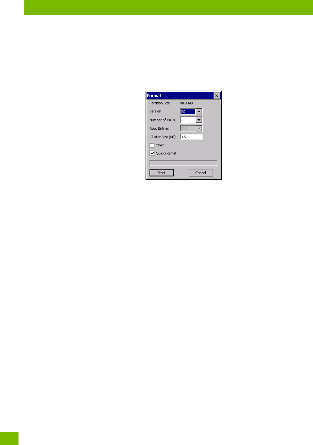
4. Tap the Format button. The Format dialog appears:
5. Choose your format options. These options include:
• Version of file system (FAT-16, for devices holding up to 4 GB; or FAT-32, for devices containing up to
32 GB).
• Number of FATs (File-Allocation Tables).
• Number of entries allowed in the root directory.
• Cluster size (.5 KB to 64 KB).
There are also two checkboxes, which govern:
• Whether to use the transaction-safe FAT file system (TFAT). This file system keeps multiple copies of
the file-allocation table, changing one while maintaining another as a backup.
• Whether to perform a quick format. Quick formatting removes all reference to data in the partition
without erasing the actual partition. The partition will be treated as empty, and new data will over-
write it.
6. Tap Start. The partition is formatted.
To mount a partition:
1. Choose the desired partition.
2. Tap the Properties button. The Partition Properties dialog appears.
3. Tap the Mount button. The partition is mounted. The asterisk appears next to its name in the par-
titions list.
The Partition Properties dialog has buttons for additional functions. Partitions can be defragmented, and
their file structure can be scanned.
Chapter 4: Configuration
Stylus Properties
95
Psion 8516 Vehicle-Mount Computer User Manual
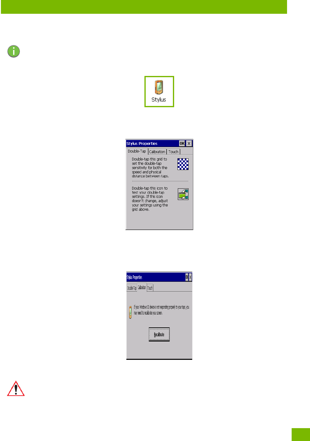
4.22 Stylus Properties
•In the Control Panel, choose the Stylus icon.
4.22.1 Double-Tap
•In the Double-Tap menu, follow the directions to tailor the sensitivity of the stylus when you tap on the
touchscreen.
4.22.2 Calibration
Touchscreens rarely require recalibration. However, if your touchscreen has never been calibrated or if you
find that the stylus pointer is not accurate when you tap on an item, follow the directions below.
• Choose the Calibration tab, and then tap on the Recalibrate button.
• Follow the directions in the Calibration tab to recalibrate the screen You will be prompted to save the
calibration data.
4.22.3 Touch
This tab allows you to disable the touchscreen.
Note: Touchscreen calibration may not be enabled on your unit. If your screen appears to require
recalibration, contact your supervisor.
Note: If you do not receive a prompt to save your data, there could be a problem with your touch-
screen hardware. Contact your Psion representative.
Chapter 4: Configuration
System Properties
Psion 8516 Vehicle-Mount Computer User Manual
96
• Choose the Touch tab. Select the checkbox next to Disable the touch panel.
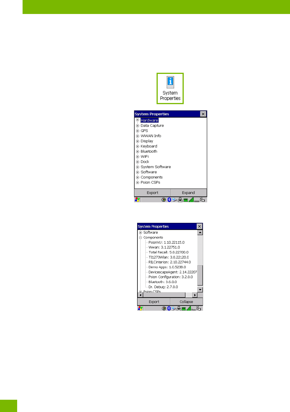
4.23 System Properties
This program identifies the computer’s software and hardware components, indicating which components
are installed, their identification, version or pa numbers, and whether they are enabled or disabled.
•In the Control Panel, choose the System Properties icon.
•By choosing the Expo button, you can create a log (SystemPropeies.xml) of your current components,
which will be placed in the My Device folder in Windows Explorer.
• Instead of expanding each section of items individually, you can also choose to open all the lists at once
by choosing the Expand button, which will then change to a Collapse button to enable you to collapse
all the sections as well.
Chapter 4: Configuration
Total Recall
97
Psion 8516 Vehicle-Mount Computer User Manual
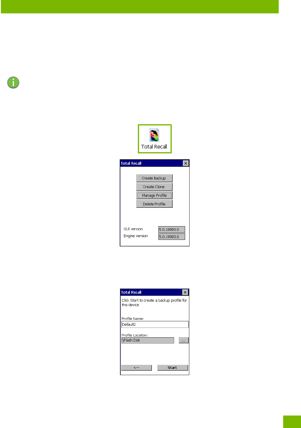
4.24 Total Recall
Total Recall is a Psion utility developed to maintain applications and settings during a cold boot, as well as
clone settings to other devices. This utility creates a restore point of a device at a known state. This can be
used as a backup of the device (the administrator can clean the terminal and restore the profile at any
time), or a clone (the administrator can store different configurations for different uses to clone to other
Vehicle-Mount computers).
•In the Control Panel, choose the Total Recall icon.
In the startup up screen, you can choose from four options: Create Backup, Create Clone, Manage Profile,
and Delete Profile.
4.24.1 Creating a Backup
•Tap on the Create Backup button to begin the process.
This dialog box displays the Profile Name and the storage destination for the profile file.
•In the Profile Name field, type a name for a profile.
• If you want to choose another location for your backup file (optional), tap on the [...] button to the
right of the Profile Location field and choose one of a number of folders.
Note: Total Recall works differently (e.g. restore on cold boot or on clean boot) on different OS
platforms and versions (e.g. Windows CE 5.0, 6.0, Windows Mobile, Windows Embedded Vehi-
cle-Mount). For detailed information and other updates on Total Recall information, please
go to the Ingenuity Working website at:
http://community.psion.com/knowledge/w/knowledgebase/total-recall.aspx
Chapter 4: Configuration
Creating a Clone
Psion 8516 Vehicle-Mount Computer User Manual
98
-Tap on Start. A backup of the current settings will be created and saved to the specified location.
The unit will then reboot.
To view profiles and choose restore options, refer to “Managing Profiles” on page 99.
4.24.2 Creating a Clone
Cloning allows you to copy settings or configurations from one computer to another. There are two types of
clones to choose from: a Full Clone and a Settings Only Clone.
A Full Clone contains all files, most of the registry, and the settings files.
A Settings Only Clone can be copied to a wider array of devices, but it should not be used as an autorestore
profile.
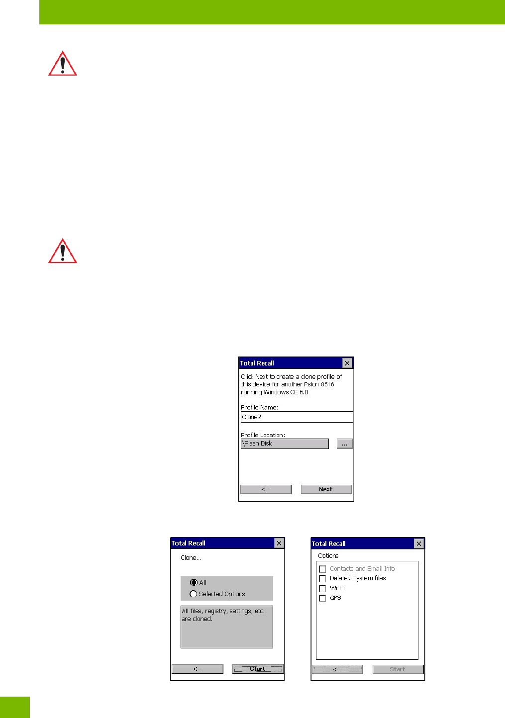
•Tap on the Create Clone button to begin the process. Your 8516 model type and OS will be identified in
the cloning statement to ensure that you target devices of the same type. Give the clone profile a
name and location, then tap on Next.
• In this menu, select All for a Full Clone, or Selected Options for a Settings Only Clone. If you choose
Selected Options, a menu will open to enable you to decide which options you want cloned.
Important: Any profile not stored in persistent memory (Flash Disk, external USB drive) will
be erased during a clean boot, therefore you should store profiles on a persistent
drive.
When performing an autorestore, the program only searches for the profile located
in the \Flash Disk\TotalRecall folder. If you store your profile anywhere else it will
not be restored. Only one profile can reside in that folder.
Important: The target device for a Full Clone MUST have the same model type and OS build as
the source, otherwise problems can occur. For example, if the target device has a
newer build of the OS, the new build may have a different set of registry keys that
may conflict with the source.
Chapter 4: Configuration
Managing Profiles
99
Psion 8516 Vehicle-Mount Computer User Manual
4.24.3 Managing Profiles
You can view profiles and choose profile options from the menus in this section.
4.24.3.1 Viewing a Profile
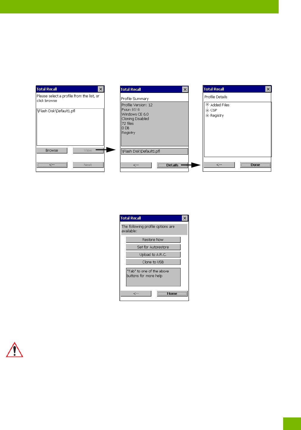
•Tap on the Manage Profile button to see your list of profiles. Highlight a profile, and then you can
choose to View the Profile Summary and go on to the next menu, Profile Details.
4.24.3.2 Profile Options
•Tap on the Manage Profile button to see your list of profiles, as shown above. Highlight a profile, and
tap on the Next button to choose from options to restore or clone the profile. You can choose from
four profile options: Restore Now, Set for Autorestore, Upload to A.R.C., and Clone to USB.
• Next, tap on the option button you want to use:
Restore Now – restores the profile immediately. If you are restoring a profile that is a backup or Full
Clone, the computer will clean reset first; if the profile is a Settings Only Clone, it will not.
Set for AutoRestore – creates a profile that is automatically restored following a cold reset or a clean
start. The profile is stored in the \Flash Disk\TotalRecall folder.
List of profiles Profile Summary Profile Details
Important: After setting an autorestore profile, that profile will overwrite any other profile
already placed in the \Flash Disk\TotalRecall folder.
In an autorestore, Total Recall only restores the profile located in the \Flash
Disk\TotalRecall folder. If you store your profile anywhere else it will not be
restored.
Chapter 4: Configuration
Deleting a Profile
Psion 8516 Vehicle-Mount Computer User Manual
100
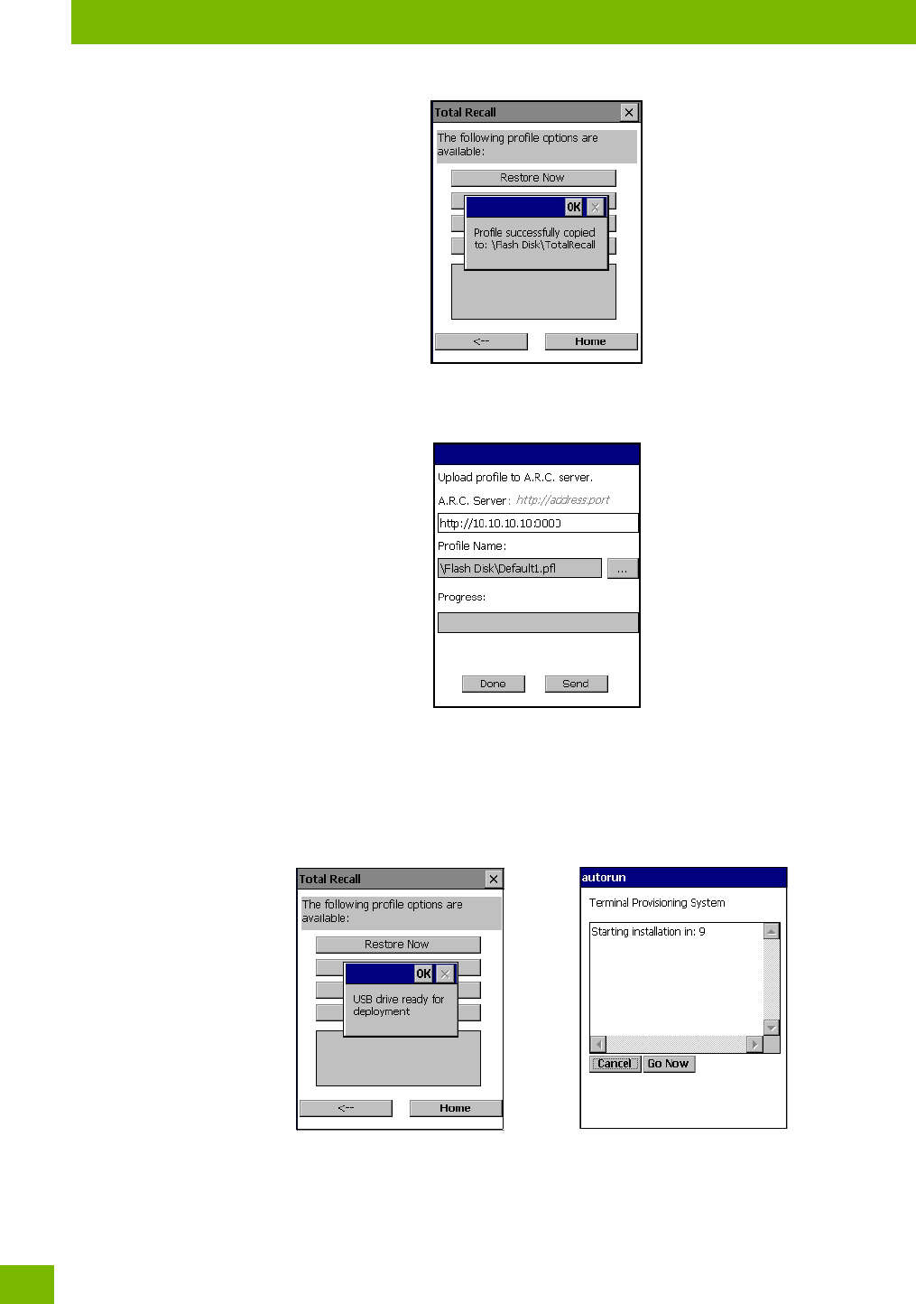
Upload to A.R.C – uploads the profile to the Active Remote Configuration server. After you tap on
Send, a message will come up either confirming that the upload was complete or that the connection
to the server failed.
Clone to USB – writes a clone of the profile to the USB drive. After you tap on the button, a message
will come up either confirming that the USB drive is ready for deployment, or that it is not available.
When you are ready to install the profile on another unit, turn on the next computer to be cloned and
insert the USB key. The profile will be automatically installed to the computer’s \Flash Disk\TotalRecall
folder. There is a short delay in deployment so that you can cancel the process if needed.
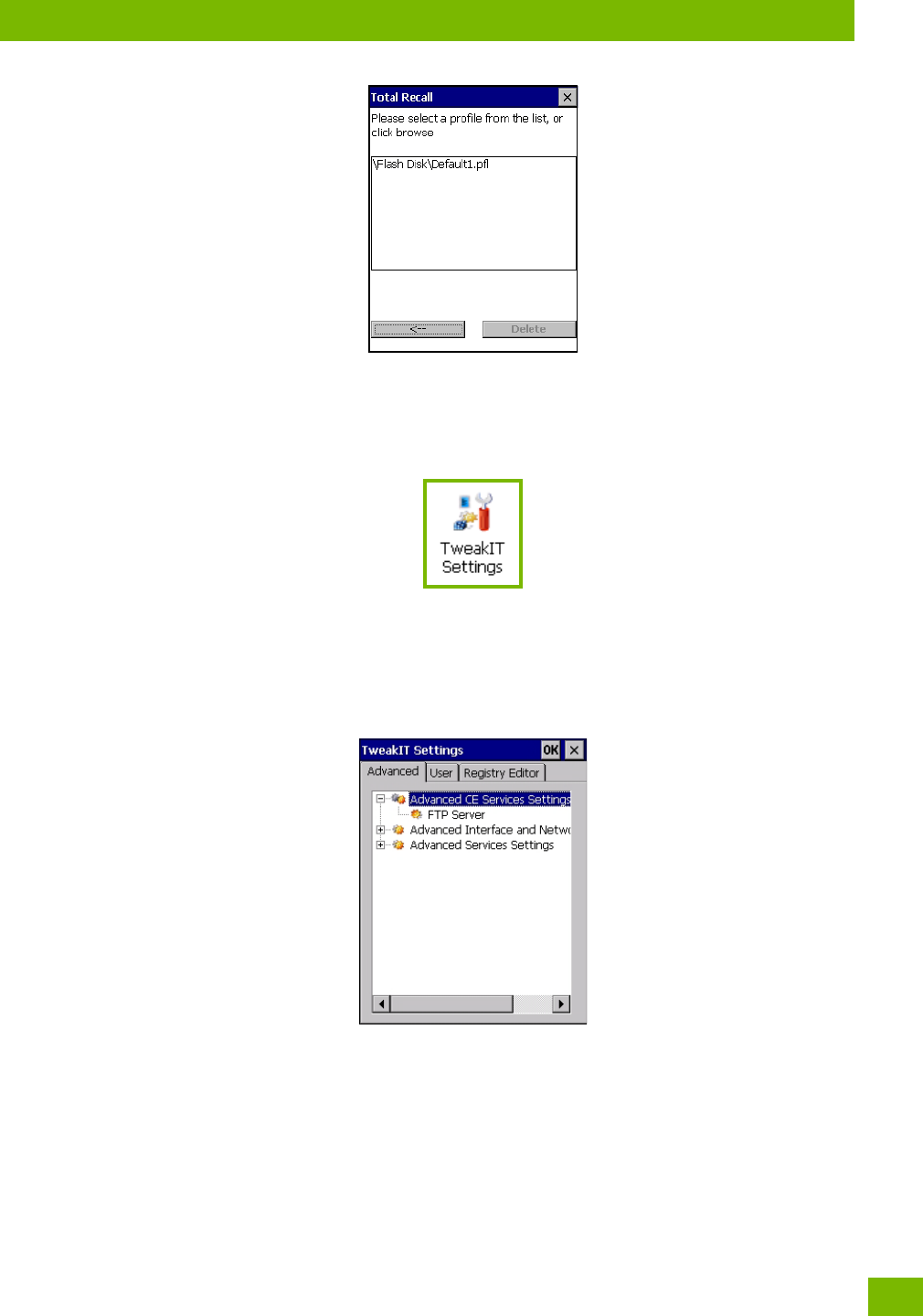
4.24.4 Deleting a Profile
•In the Total Recall home screen, tap on Delete Profile.
• In the next screen, locate your backup file, and tap on OK.
USB drive prepared for cloning Autorun installation on next 8516
Chapter 4: Configuration
TweakIt
101
Psion 8516 Vehicle-Mount Computer User Manual
A warning pop-up screen appears asking if you’re certain that you want to delete this file.
•Tap on Ye s to delete the file.
4.25 TweakIt
This utility allows you to ‘tweak’ or adjust Advanced system settings (interface, network, servers, driver, and
radio) and provides a Registry Editor.
4.25.1 Advanced
4.25.1.1 Advanced CE Services Settings
FTP Server
This option is enabled by default to allow file transfers. Keep in mind that data transfer in either direction is
restricted to the Temp folder—that is, data are always loaded from the FTP Server to the Temp folder and
from the Temp folder to the FTP Server.
If this option is disabled, a warm reset must be performed to accept the change.
Chapter 4: Configuration
Advanced
Psion 8516 Vehicle-Mount Computer User Manual
102
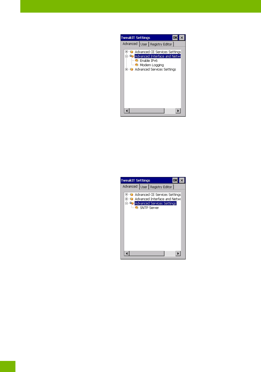
4.25.1.2 Advanced Interface and Network Settings
Enable IPv6
This option allows you to enabled Internet Protocol specification, version 6, that has been published to
enable 128-bit IP addresses (replacing version 4).
Modem Logging
When this option is enabled, the 8516 logs AT commands (e.g., dial-out information, password string, etc.)
that the administrator can monitor for debugging purposes. Modem commands are stored in: \MdmLog.t.
4.25.1.3 Advanced Services Settings
SNTP (Simple Network Time Protocol) Server
The SNTP Server Name typed in this dialog box is used to synchronize 8516 time with the server time. A
warm reset must be performed once the server name as been entered.
Chapter 4: Configuration
Wi-Fi Config
109
Psion 8516 Vehicle-Mount Computer User Manual
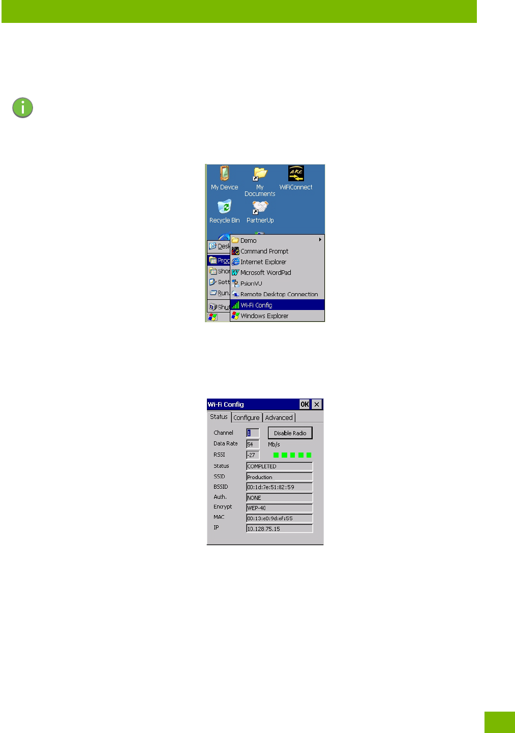
4.28 Wi-Fi Config
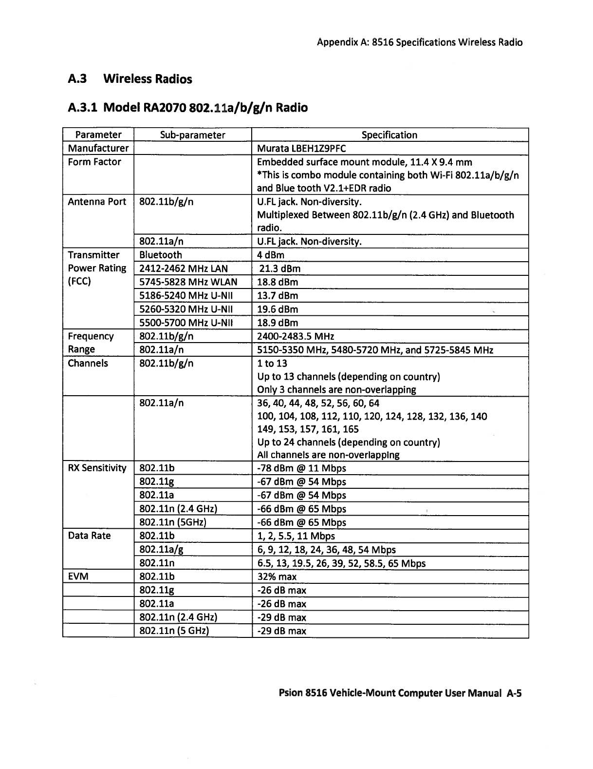
The Wi-Fi Config application is used to configure the 8516 802.11a/b/g/n radio for one or more wireless
network profiles. A network profile contains settings for SSID (Service Set Identifier) and security options.
To launch the Wi-Fi Config application:
•Tap on Start>Programs>Wi-Fi Config.
The Wi-Fi Config screen is displayed.
4.28.1 Wi-Fi Config: Status
The Status tab displays information about the wireless network to which the 8516 is configured to connect.
When there are no network profiles configured, this tab is not populated.
Disable/Enable Radio: This button toggles between Disable Radio and Enable Radio depending on whether
the radio is turned off or on.
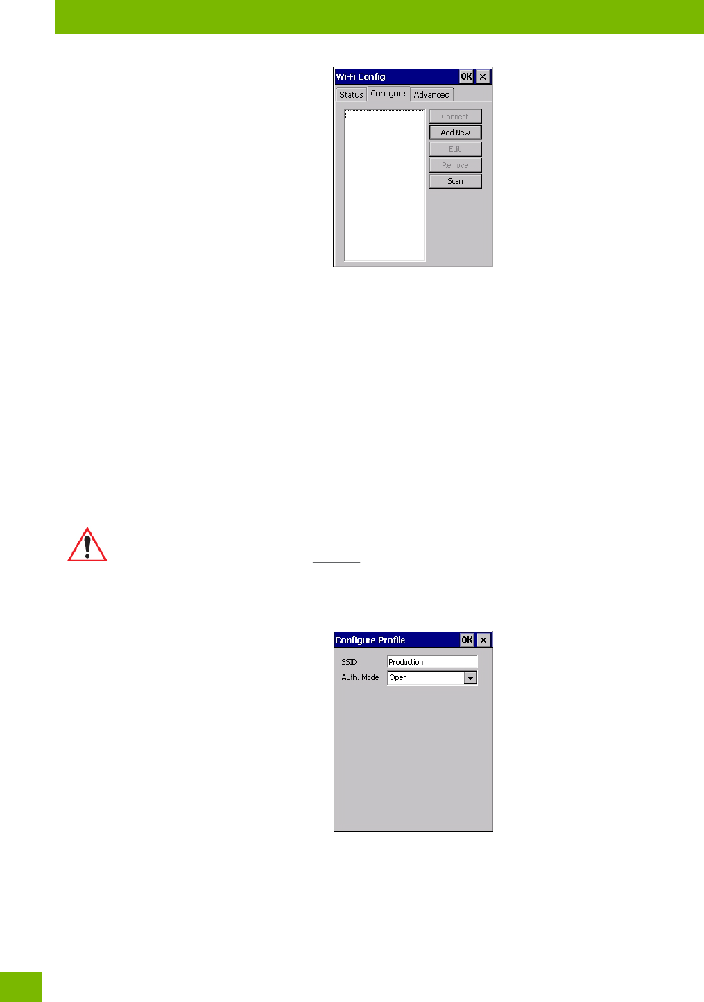
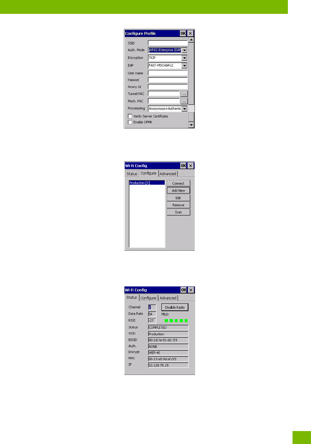
4.28.2 Wi-Fi Config: Configure
• To configure the radio for a wireless network, tap on the Configure tab.
Note: In most situations, the configuration of your 802.11 radio will require parameter setting and
access keys from a network administrator.
Chapter 4: Configuration
Wi-Fi Config: Configure
Psion 8516 Vehicle-Mount Computer User Manual
110
Connect: Used to connect to an already existing wireless network configuration.
Add New: Used to create a new wireless network configuration.
Edit: Used to change values in an already existing wireless network configuration.
Remove: Used to delete a wireless network configuration.
Scan: Used to detect and list available wireless networks. You can highlight a network in the list, and tap on
Add New to activate the network.
There are two methods available when configuring a radio network—you can either scan for an existing
network or manually create a network. If you tap on the Scan button, a list of networks detected by the
radio is displayed. Highlighting one of the listed networks and tapping on the Add New button creates a new
profile that is completed based on the security capabilities detected by the radio. You may need to add ad-
ditional information, depending on your network requirements.
4.28.2.1 Manually Creating a Network
If you tap on the Add New button rather than the Scan button, you can create a network manually.
• Enter the SSID (Service Set Identifier) for your network.
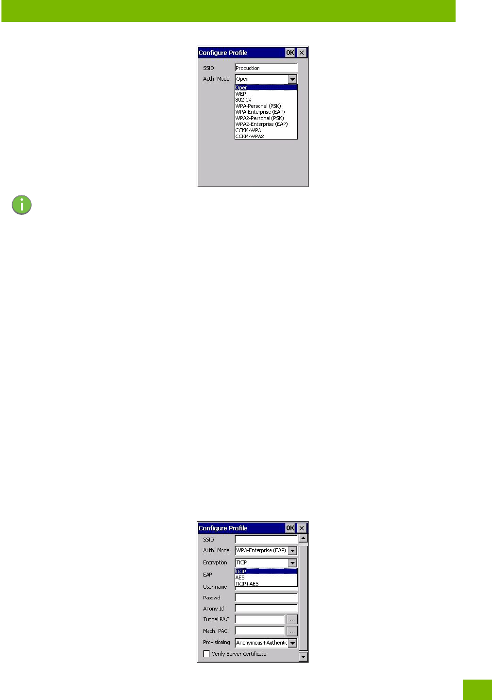
4.28.2.2 Authentication Mode
The 8516 supports several classes of authentication—Open, WEP, WPA/WPA2 (Personal PSK, Enterprise,
CCKM-WPA, CCKM-WPA2), and 802.1x with EAP. Tapping on the Auth. Mode menu displays your authentica-
tion options.
Important: The steps below describe how to manually create a network. Keep in mind that this
is intended only as an example and may vary from your own network requirements.
If, for example, you are using a different type of security for your network, the
fields you complete may not match those described here.
Chapter 4: Configuration
Wi-Fi Config: Configure
111
Psion 8516 Vehicle-Mount Computer User Manual
Open Authentication
Open authentication does not provide security. When this option is chosen, the 8516 will connect to wireless
networks which do not use authentication or encryption.
WEP (Wired Equivalent Privacy)
WEP provides static security to prevent others from accidentally accessing your network. If you choose this
option, you can specify the type of WEP authentication—Open or Shared, the WEP security key length—64
bit or 128 bit and the key type—ASCII or Hex. WEP Key fields are also provided where you can specify a 5 or
13 ASCII character sequence or an equivalent 10 or 26 Hexidecimal digit sequence that matches the active
WEP key on the access point.
WPA & WPA2 Personal PSK (Pre-Shared Key)
When PSK is selected, either WPA Personal PSK or WPA2 Personal PSK—a shared key must be configured
on both the access point and the Vehicle-Mount computer. One of the following can be chosen from the En-
cryption drop-down menu: TKIP, AES or TKIP+AES.
802.1X, WPA & WPA2 Enterprise, CCKM-WPA & CCKM-WPA2
These authentication modes use 802.1X with EAP authentication. When 802.1X is selected, the 8516 uses
WEP encryption with automatic (as opposed to static) keying. For the others, the user may choose TKIP,
AES or TKIP+AES encryption.
4.28.2.3 Encryption
The Encryption menu allows you to choose the type of encryption that will be used to protect transmitted
data. Choose an Encryption method valid for your network from the drop-down menu. Only the Encryption
options that are compatible with the type of Auth. Mode you’ve chosen will be listed. In fact, in some cases,
this menu will not be available at all.
Note: Each Auth. Mode has a unique Configure Profile screen attached to it with fields appropriate
to the authorization mode you’ve chosen.
Chapter 4: Configuration
Wi-Fi Config: Configure
Psion 8516 Vehicle-Mount Computer User Manual
112
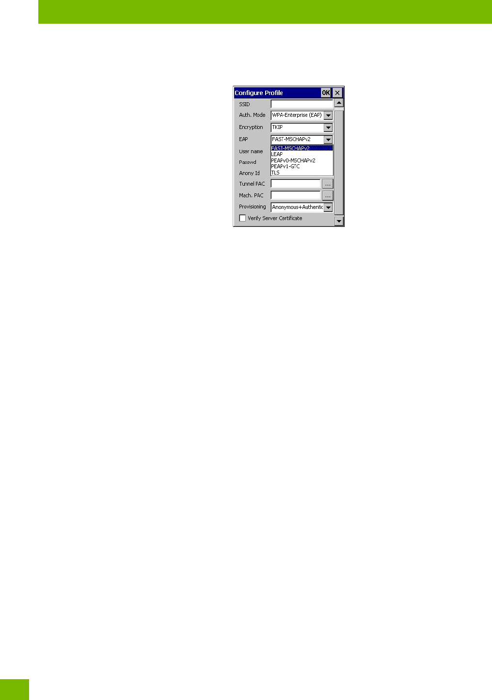
4.28.2.4 EAP
This menu allows you to choose the EAP (Extensible Authentication Protocol) type used for 802.1x authen-
tication to an access point.
The following EAP types are supported by Wi-Fi Config:
•TLS: Provides strong security via the use of client certificates for user authentication.
•PEAPv0-MSCHAPv2: Provides secure user authentication by using a TLS tunnel to encrypt EAP traf-
fic. MSCHAPv2 is used as the inner authentication method. This is appropriate for use against Windows
Active Directory and domains.
•PEAPv1-GTC: PEAP authentication using GTC as the inner method which utilizes one time passwords
(OTPs) for authentication against OTP data bases such as SecureID.
•LEAP: Is an authentication method for use with Cisco WLAN access points. LEAP does not require the
use of server or client certificates. LEAP supports Windows Active Directory and domains but requires
the use of strong passwords to avoid vulnerability to off-line dictionary attacks.
•FAST-M SCHAPv 2 : Is a successor to LEAP and does not require strong passwords to protect against
off-line dictionary attacks. Like LEAP, EAP-FAST does not require the use of server or client certificates
and supports Windows Active Directory and domains.
• Complete the fields in the Configure Profile screen. If you’re uncertain about some of the options,
your system administrator will be able to provide the correct information for your wireless network.
• Once you’ve completed the necessary fields, tap on OK.
4.28.2.5 Verify Server Certificate
When the Verify Server Certificate box is checked, the 8516 will verify the certificate provided by the au-
thentication server during the authentication process. This requires that an appropriate certificate be man-
ually installed on the 8516 for the verification.
4.28.2.6 Enable OPMK
When used with compatible wireless infrastructure, Opportunistic Key Caching (OPMK) reduces the number
of full authentications required when roaming. Only available with WPA2-Enterprise (EAP) authentication
mode.
Chapter 4: Configuration
Configuring TCP/IP
113
Psion 8516 Vehicle-Mount Computer User Manual
4.28.2.7 Connecting the Wireless Network
Your configured network is listed in the Configure tab. An [X] next to a network indicates that this is the
network to which the 8516 will connect.
•Tap on the Connect button to activate your network.
The Status tab is displayed. The Status field displays ASSOCIATING while the 802.11a/b/g/n radio attempts
to connect to the network. Once the association is complete, the Status tab is populated with the appropri-
ate information about your network.
4.28.3 Configuring TCP/IP
If your network is not using a DHCP server, you will need to assign an IP address.
4.28.3.1 IP Address
To assign an IP address for your 8516:
Chapter 4: Configuration
Configuring TCP/IP
Psion 8516 Vehicle-Mount Computer User Manual
114
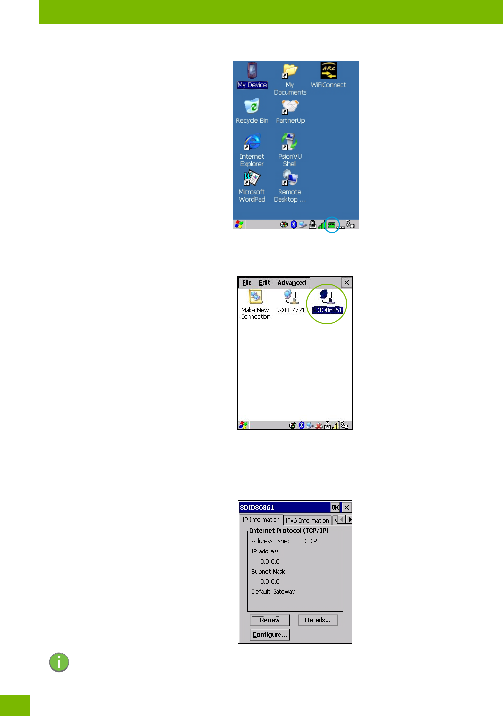
•Tap on the radio icon in the taskbar,
or
Tap on Start>Settings>Network and Dial-up Connections. Tap on the radio icon
for which you want to assign an IP address—in the sample screen below, the icon is labelled SDIO86861.
The Wireless Statistics screen is displayed.
• Tap on the IP Information tab.
Figure 4.7 SDIO86861 IP Information
Note: When DHCP is enabled, tapping the ‘Renew’ button forces the 8516 to renew or find a new IP
address. This is useful if, for example, you are out of communication range for a longer period
of time and your Vehicle-Mount is dropped from the network.
Chapter 4: Configuration
Wi-Fi Config: Advanced
115
Psion 8516 Vehicle-Mount Computer User Manual
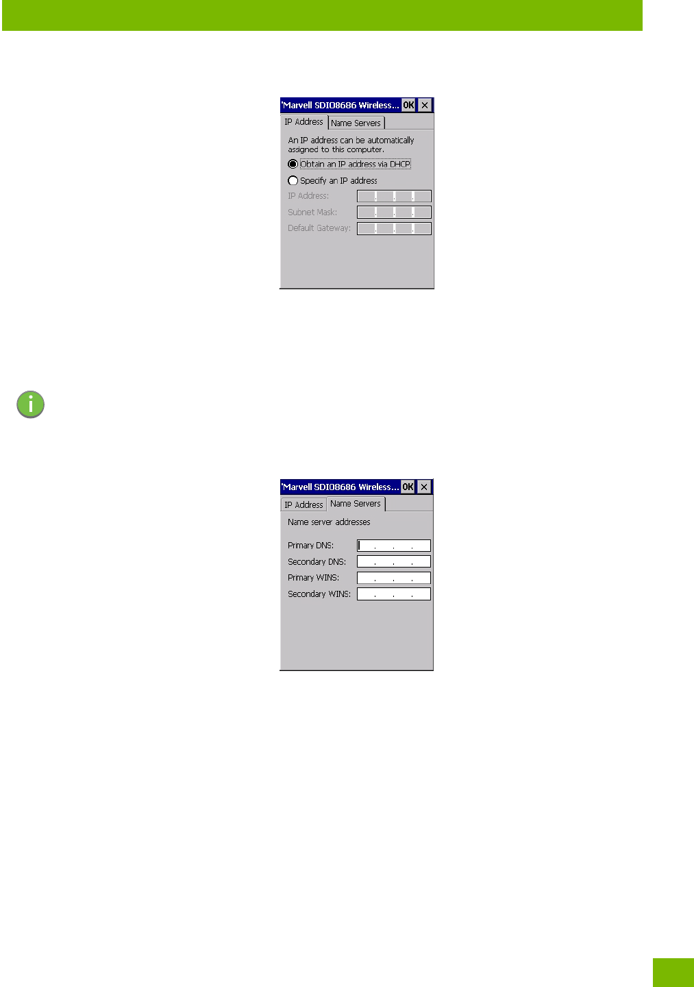
To define a static IP address:
•Tap on the Configure button.
• Tap on the radio button next to Specify an IP address to select it.
•Type an IP, Subnet Mask and Default Gateway address in the appropriate fields. Press [ENTER] to
save your information.
4.28.3.2 Name Server
•In the SDIO86861 IP Information tab (see Figure 4.7), tap on the Configure button.
•Tap on the Name Servers tab.
The DNS and WINS fields in the Name Servers tab allow you to specify additional WINS and DNS resolvers.
The format for these fields is ###.###.###.###.
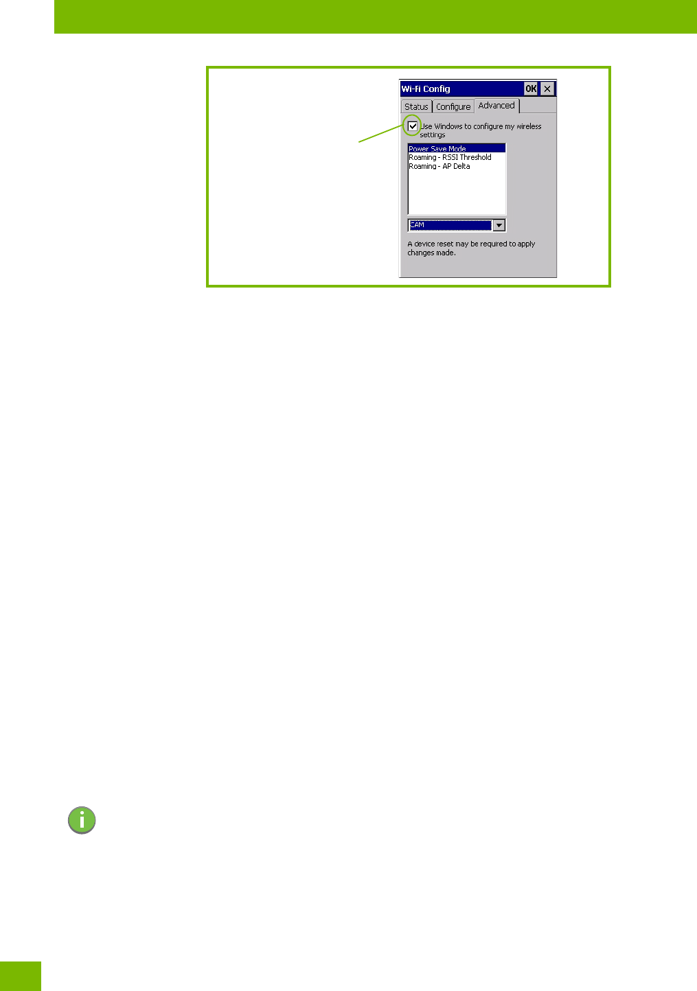
4.28.4 Wi-Fi Config: Advanced
Use Windows to configure my wireless settings
In the Advanced tab you can set Windows to configure the radio, using Wireless Zero Config.
• Tap on the checkbox to the left of Use Windows to configure my wireless settings to enable this
option.
Note: If DHCP is enabled, name server addresses are assigned automatically.
Chapter 4: Configuration
Monitoring the Network Connection
Psion 8516 Vehicle-Mount Computer User Manual
116
Power Save Mode
This allows you to set the 802.11 power saving mode of the radio to: CAM (continuous access—always on)
(recommended); or MAX_PSP (maximum power saving mode).
Roaming - RSSI Threshold
This sets the RSSI threshold value, below which the radio will start scanning for new access points when
roaming. Values range from -55 to -90 dBm.
Roaming - AP Delta
This sets how much greater (in dBm) the RSSI of a new access point must be than the RSSI of the currently
associated access point in order for the Vehicle-Mount to initiate a roam. Values range from 5 to 30 dBm.
Concluding the Wi-Fi Configuration
If you’ve made changes in the Advanced menus, you will need to warm reset your 8516.
•Choose Start>Shutdown>Warm Reset.
• A dialog box is displayed letting you know that you will lose all unsaved data. Tap on OK.
Once the reset is complete, if you checked the box next to Use Windows to configure my wireless set-
tings, the Wireless Zero Config screen is displayed on the Vehicle-Mount. Refer to Appendix F: “Wireless
Zero Config Settings” for details.
4.28.5 Monitoring the Network Connection
The radio signal icon in the taskbar indicates the strength of the communication link with an 802.11 access
point.
To access the radio signal icon:
• Tap on the radio icon in the taskbar to display the wireless statistics dialog box.
To access the radio signal icon using the keyboard:
• Press the [Windows] key to display the Start Menu.
• Highlight Shortcuts and then choose System Tray from the sub-menu.
• Use the [LEFT] and [RIGHT] arrow keys to highlight the radio signal icon in the taskbar.
• Press [ENTER] to display the Wireless Statistics dialog box.
4.29 WiFi Connect A.R.C.
The WiFiConnectARC utility on the desktop provides a quick method to configure a device for use on a
private network, primarily for use with Active Remote Configuration (A.R.C.).
Tap here to add a checkmark
to activate the Windows radio
configuration.
Note: Moving in and out of the radio coverage area can have varying effects on a network session.
At times, you may need to renew your connection by logging in again.

Chapter 4: Configuration
WiFi Connect A.R.C.
117
Psion 8516 Vehicle-Mount Computer User Manual
When you click on this icon, WiFiConnect A.R.C. configures the default WiFi interface. The WEP key is set to
PsionPsion123. The SSID is set to Psion. The default interface becomes the active interface. Keep in mind
that you must configure the access point and the Vehicle-Mount(s) to use the same settings.
Refer to the Active Remote Configuration (A.R.C.) Administrators Guide, PN 8000252, for details about up-
dating devices on your network. This manual is available at:
http://community.psion.com/knowledge/w/knowledgebase/1189.aspx

Chapter 5: Accessories
Network Access
Psion 8516 Vehicle-Mount Computer User Manual
124
• Connect your network Ethernet cable to the Ethernet port on the adaptor cable.
5.4.1 Network Access
The 8516 automatically loads the appropriate drivers to communicate with the USB-Ethernet converters.
Network Addressing
The host application uses standard TCP/IP protocol to name, locate, and communicate with a specific 8516
on the network.
If a link is established between an 8516 and a host, the application on the host and on the computer must
have a recovery mechanism in the event that the 8516 is disconnected, interrupting the link.
5.5 8516 Mounting Accessories: Installing the RAM Mounting Kit
The 8516 is installed using an articulating RAM Mount (Model MT34XX – 4 in. or 12 in. arm) secured to either
a Vesa or circular base.
Warning: Failure to install the mount correctly, or modifications to the mount, may result in
serious injury or damage to property. Contact Psion Technical Support or your
Psion representative if you have problems installing this mount. To ensure opera-
tor safety, you must use a calibrated torque wrench and the supplied mounting
hardware when fastening the cradle and mount. Use of this mount in vehicles
driven on public roads or highways is prohibited. Contact Psion for further details.
Before mounting an 8516 in a vehicle, there are a number of operator safety
issues that require careful attention. When mounting an 8516 use only approved
Psion mounting hardware and mounting parts which are specific to the 8516
model purchased. An improperly mounted 8516 or use of non-approved parts may
result in one or more of the following: operator injury, property damage, operator
visibility obstruction, operator distraction, and/or poor ease of egress for the
operator. Psion strongly recommends that you seek professional mounting advice
from the vehicle manufacturer.
If it is necessary to mount the 8516 overhead, or in any position that could cause
injury to the operator should the unit fall, it is critical that a secondary tether or
other failsafe device be installed.
The following restrictions must be strictly enforced:
Do not use the mount and/or the 8516 as a hand-hold. Using the mount in this
manner may cause the person to fall or dislodge the mounting hardware and/or
mounts.
Do not add weight or attach any other items to the mount or 8516. Additional ele-
ments may fall causing injury, or may increase the chance of failure and/or
damage in mounting hardware and/or mounts.
Mounts used in industrial or vibration generating environments may be subjected
to fatigue, stress, and/or part wear. A periodic inspection of the mounting hard-
ware and mounts should be performed to ensure parts are retightened to the
correct torque, free of fractures, excessive wear, and/or other environmental
damage. Any parts found to be unsafe should be removed and replaced immedi-
ately. After inspection or replacement of parts, readjust the mount as outlined in
step 4 below and tighten with the approved tightening tool (P/N 9000594).
Cable routing within a vehicle cab also requires careful consideration, especially
for separately connected scanners and other devices with loose cables. If you are
unable to obtain suitable advice, contact Psion for assistance. Note also that for
better protection, the equipment should be mounted inside the vehicle roll cage.
Use of the Powered Fork Lift Cradle while charging the fork truck battery
is prohibited.

Chapter 5: Accessories
Component Part Numbers
125
Psion 8516 Vehicle-Mount Computer User Manual
5.5.1 Component Part Numbers
The table below lists the mounting component part numbers and legend for Figure 5.10 on page 129.
5.5.2 MT33XX RAM Mounting Kit Specifications
• Max. Load: 15kg
• Articulating Range: Spherical through 180 degrees.
• Shock Rating: Meets IEC60721-3-5 CLASS 5M2
• Test Method IEC60068-2-64 Fh
• Vibration Rating: Meets IEC60721-3-5 CLASS 5M2
• Test Method IEC60068-2-27 Ea
Important: Safeguards
To avoid possible injury, this device must be properly secured when in a moving
vehicle.
Keep this device away from magnetic fields.
Do not place the computer near a television or radio receiver.
Do not disassemble your 8516 computer — there are no user-serviceable parts
inside.
Table 5.1 Mounting Components and Figure Legend
Figure Legend Description Part Number
A 8516 Vehicle-Mount Computer
B RAM Vesa Base 9001934
C Washer M8 Internal Tooth 9008800
D Screw M8 x 12 Pan Head 9004517
E RAM Standard Arm 9001805
F RAM Circular Base 9001804
G Screw M8 x 25 Pan Head 9004518
H Screw M8 x 25 Flat Head 9004522
J Nut M8 x 1.25 9008801
L Mounting Kit MT3505 (Clamp base (for 4" or 12" RAM arm, 2" max. width) 9007505
M Mounting Kit MT3507 (Clamp base (for 4" or 12" RAM arm, 3" max. width) 9007507
N Mounting Kit MT3509 (Rail base (for 4" or 12" RAM arm, 1 1/4" to 1 7/8") 9007509
P Mounting Kit MT3510 (Rail base (for 4" or 12" RAM arm, 2" to 2 1/2") 9007510
Chapter 5: Accessories
Preparation
Psion 8516 Vehicle-Mount Computer User Manual
126
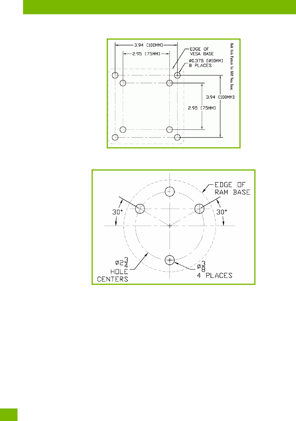
Figure 5.4 Bolt Hole Pattern For RAM Vesa Base
Figure 5.5 Bolt Hole Pattern For RAM Circular Base
5.5.3 Preparation
The RAM articulating mount can be installed in a variety of orientations (see Figure 5.6 on page 127). Select
the best orientation for your specific application. Preferred orientations maintain the centre of mass of the
computer assembly, directly over the centre of the base (see Figure 5.6).
Chapter 5: Accessories
Preparation
127
Psion 8516 Vehicle-Mount Computer User Manual
Figure 5.6 Orientation Of Vehicle-Mount Assembly
Figure 5.7 Tightening Tool P/N 9000594
The mounting platform on which you secure the computer must be strong enough to support 25 kg. Never
attach the mount to a plastic dash or a wooden platform without the appropriate backing plate and bracing.
When selecting a mounting location, you must provide the operator access at the top, bottom, and sides.
70°
15°
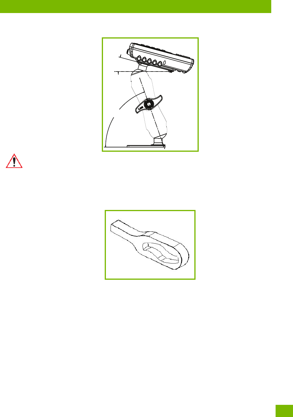
Important: The tilt and rotation of the cradle can be easily adjusted by the operator. Ensure
that if the handscrew is loosened and the cradle slips, the operator and any equip-
ment cannot be damaged by it. Also note that under extreme vibration, the mount
may slowly ‘settle’, requiring readjustment and tightening of the handscrew. Psion
offers a tightening tool (P/N 9000594) which can be used to minimize settling.
Chapter 5: Accessories
Installation
Psion 8516 Vehicle-Mount Computer User Manual
128
5.5.4 Installation
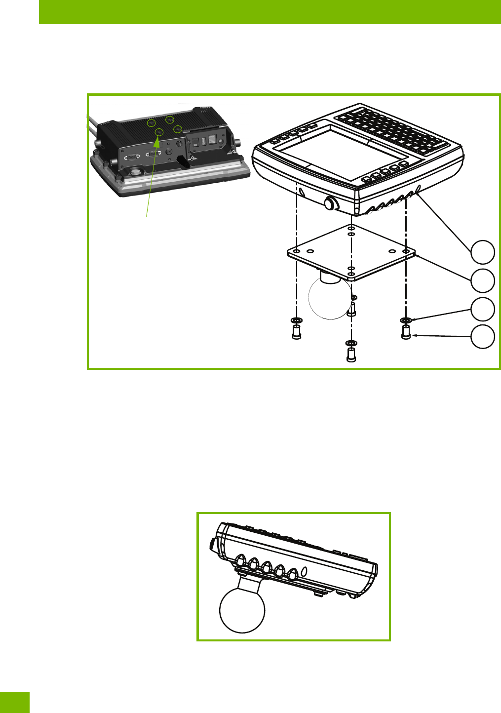
Figure 5.8 8516 Vehicle-Mount Computer With Mounting Bracket
1. Attaching the mounting bracket and RAM base to the computer:
1. The kit provides four screws and washers that are used to secure the mounting bracket to the com-
puter. Figure 5.8 provides a diagram and a legend to help you attach the mounting bracket and the
RAM Vesa base to the computer. To do this:
• Apply Loctite 243 to the screw threads (Note: Loctite is not supplied by Psion ). Match the four screw
holes on the back of the 8516 with the appropriate pairs of holes on the bracket and screw them
together by placing the Screw (D) through the Washer (C) and the RAM Vesa Base (B), and then affix-
ing it to the 8516 (A).
• Torque to 26 in-lbs.
Figure 5.9 Mounting Bracket Attached To The 8516
1. Secure the RAM Base to the local platform and attach RAM Standard Arm:
A
C
B
D
Back of 8516 showing
location of screw holes.
Chapter 5: Accessories
Positioning the 8516
129
Psion 8516 Vehicle-Mount Computer User Manual
1. Use the supplied bolt hole pattern to drill the required holes in the local platform. Hole diameters must
not exceed 10mm [13/32 inches]. Hardware (G, H, C, and J) for securing RAM Bases (B or F) to the local
platform are in the recommended sizes (see Table 5.1 on page 125). If replacement hardware is
required, it should be consistent with these diameters. All fasteners must use a suitable locking mech-
anism to ensure that they do not loosen under shock and vibration.
• If you are assembling with the RAM Vesa Base, see Section 5.5.4.1:“RAM Vesa Base”.
• If you are assembling with the RAM Circular Base, see Section 5.5.4.2:“RAM Circular Base”.
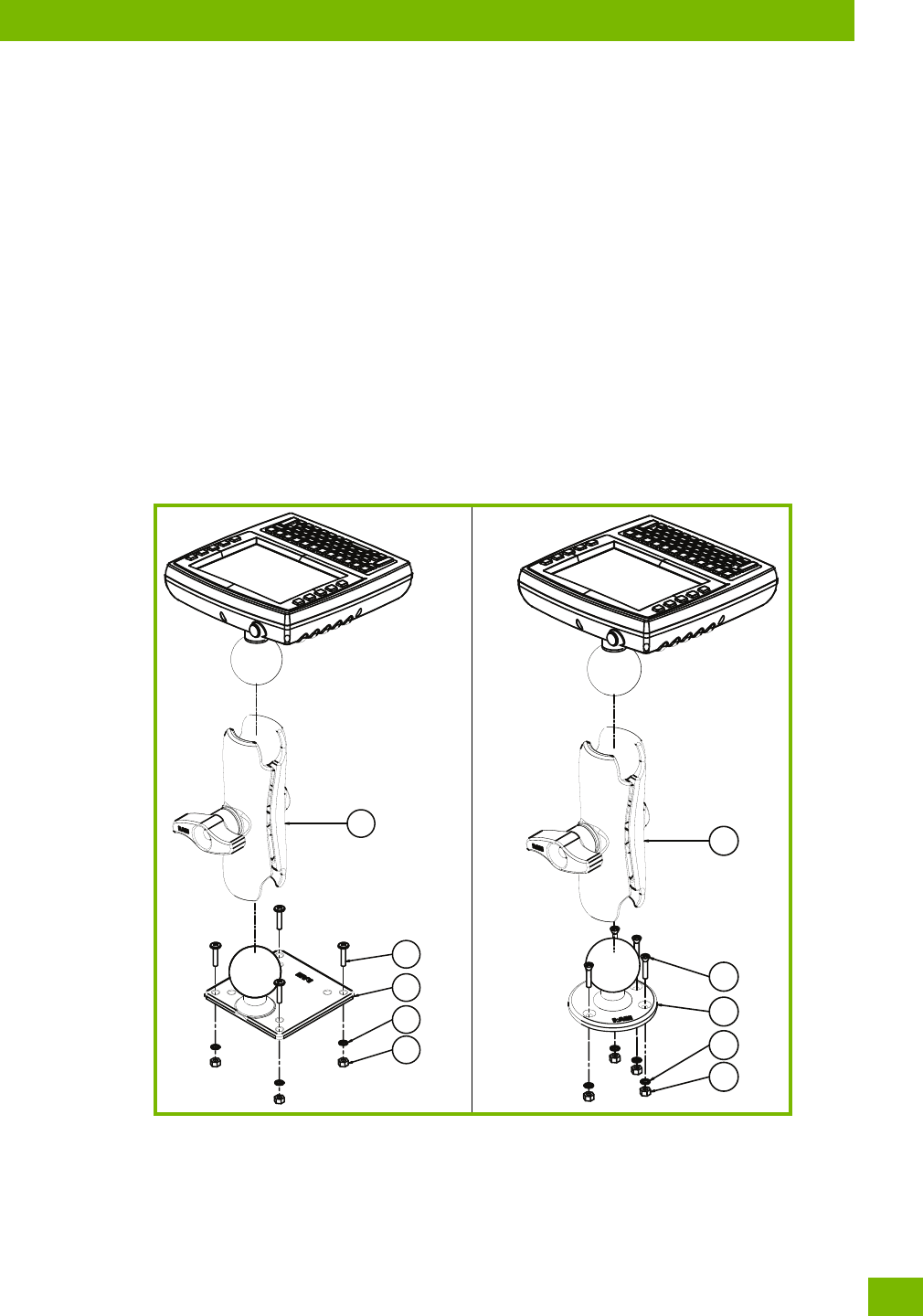
5.5.4.1 RAM Vesa Base
See Figure 5.10 on page 129. In four places, insert screw (G) through the RAM Vesa Base (B), the local plat-
form and the washer (C). Affix with nut (J). Torque to 26 in-lbs. Secure RAM Standard Arm (E) by inserting
RAM Balls into both ends of arm sockets.
5.5.4.2 RAM Circular Base
See Figure 5.10 on page 129. In four places, insert screw (H) through the RAM Circular Base (F), the local
platform and the washer (C). Affix with nut (J). Torque to 26 in-lbs. Secure RAM Standard Arm (E) by insert-
ing RAM Balls into both ends of sockets.
Figure 5.10 RAM Vesa Base RAM Circular Base
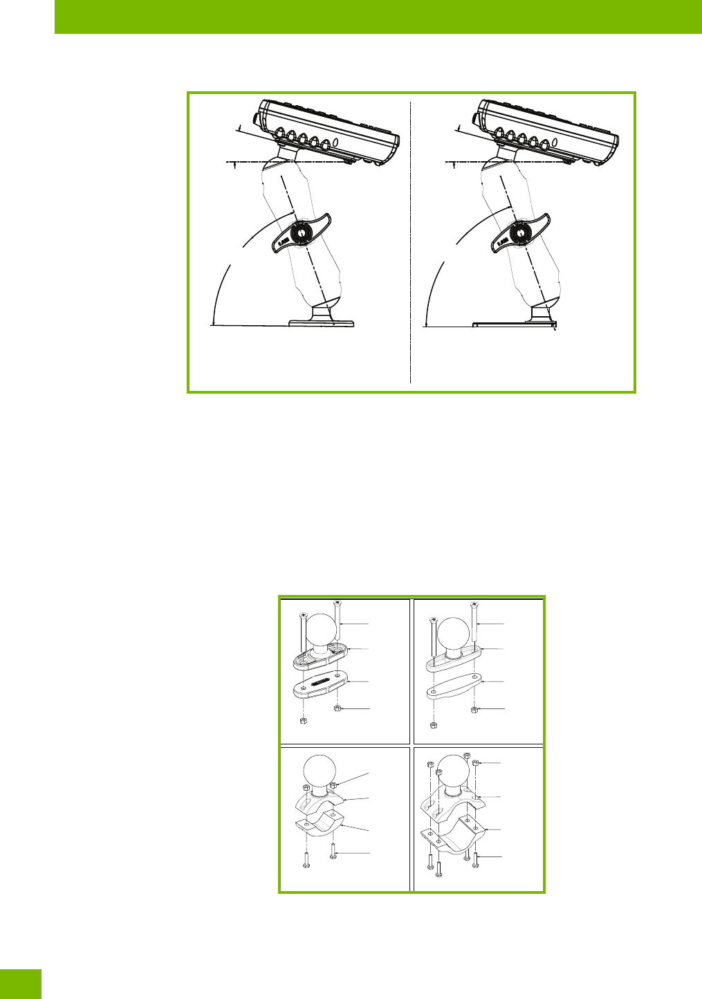
5.5.5 Positioning the 8516
Place the 8516 into the position best corresponding to the RAM hardware used (see Figure 5.11 on page 130)
and tighten by hand until secure. Refer to “8516 Mounting Accessories: Installing the RAM Mounting Kit” on
page 124 for warnings and proper tightening technique. Mount orientations shown in Figure 5.11 are consid-
ered the preferred configurations for the Circular Base to Platform and the Vesa Base to Platform.
E
J
B
C
G
E
C
J
H
F
Chapter 5: Accessories
Optional Mount Kits
Psion 8516 Vehicle-Mount Computer User Manual
130
Figure 5.11 Circular Base and Vesa Base Mount Orientations
5.5.6 Optional Mount Kits
One of the mounting kits shown in Figure 5.12 on page 130 may be substituted for the Vesa Base (B) or the
circular base (F) when mounting to a post or forklift roll cage.
To Install:
Mount the Clamp Base and Lower Base around the shaft. Place the Screw through the Clamp and the Lower
Base, and affix with the Nut. Torque to 26 in-lbs. Secure the RAM Standard Arm (E) by inserting the RAM
Balls into both ends of the arm sockets.
Figure 5.12 Optional Mount Kits
Vesa Base To PlatformCirc. Base To Platform
15°
70° 70°
15°
LOWER
BASE
NUT
CLAMP
BASE
SCREW
LOWER
BASE
NUT
CLAMP
BASE
SCREW
LOWER
BASE
SCREW
CLAMP
BASE
NUTNUT
CLAMP
BASE
SCREW
LOWER
BASE
MT3505 MT3507
MT3510MT3509
Chapter 5: Accessories
MT3250 Quick Release Mount “Turn & Lock”
131
Psion 8516 Vehicle-Mount Computer User Manual
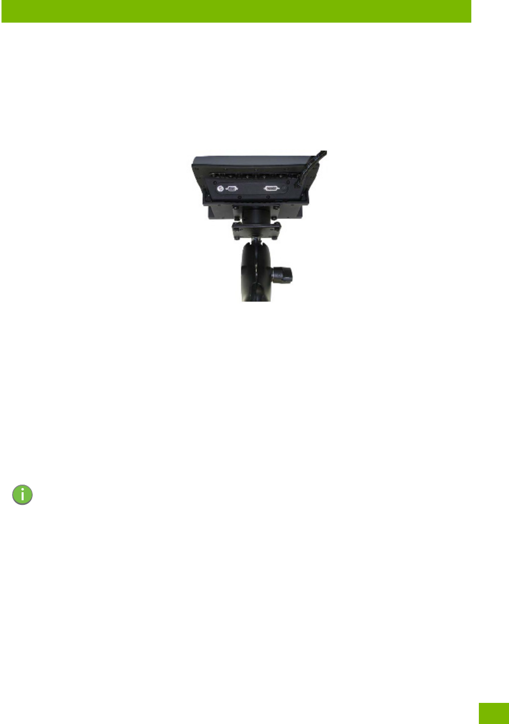
5.6 MT3250 Quick Release Mount “Turn & Lock”
The Quick Release Mount “Turn & Lock” option allows a dismount with a quick flick of the wrist and without
the need of tools. It can be used alone or in combination with the RAM mounts. The Quick Release Mount
can be used direct with the 8516 without the need for an adaptor plate.
Figure 5.13 MT3250 Quick Release Mount “Turn & Lock”
5.7 8516 Vehicle-Mount Computer Installation
5.7.1 Wiring Guidelines
Before installing the cables between the cradle and other devices, consider the following:
• Ensure that drilling holes will not damage the vehicle or its wiring.
• Protect cable runs from pinching, overheating and physical damage.
• Use grommets to protect cables that pass through metal.
• Use plastic straps and tie-downs to secure cables and connectors in their desired location, away from
areas where they may get snagged or pulled.
• Keep cables away from heat sources, grease, battery acid and other potential hazards.
• Keep cables away from control pedals and other moving pas that may damage the cables or interfere
with the operation of the vehicle.
5.7.2 Non-Vehicle Installations
Using AC power, the 8516 Vehicle-Mount Computer can be mounted at fixed locations adjacent to
cross-dock doors, manufacturing stations, or in offices.
The 110/220V Psion AC adaptor Model PS1400 should be used to power the computer from an AC source.
Note: Make sure the cables run inside the roll cage of the vehicle.

Appendix A: 8516 Specifications
The 8516 Vehicle-Mount Computer
A-3
Psion 8516 Vehicle-Mount Computer User Manual
A.1 The 8516 Vehicle-Mount Computer
A.1.1 Hardware
Physical Dimensions
• 275 mm W x 235 mm H x 90 mm D (10.83"x 9.25" x 5.54").
Weight
• 4.3 kg (9.5 lbs), includes integrated UPS battery.
Processor and Memory
• Texas Instruments® OMAP3® Processor 800 MHz.
• RAM: 512 MB RAM standard.
• Flash ROM: 1 GB.
Operating System
• Microsoft Windows® Embedded CE 6.0
A.1.2 User Interface
Colour Display
• Size 20.32 cm (8") diagonal
• Resolution 800 x 480 pixels
• Brightness 640 cd/m2
• Touchscreen Rugged 5-wire technology
Passive stylus or finger operation
Optional heater
Indicators
• Power LED
• Warning LED
Keyboard
• Alphanumeric keyboard 67-key QWERTY and AZERTY available
• Function Keys 12 dedicated function keys
• Key Illumination LED backlight
Voice and Audio
• High volume 93 dBA beeper
• Optional push-to-talk speaker/microphone
Communication Ports
• 8516 top 1 x USB host port
• 8516 bottom 2 x full function UART RS-232 with 5V / 1000mA for external devices
1 x USB host port
1 x powered USB host port with 12V / 1.5 A
1 x 3.5mm audio jack
Note: Performance specifications are nominal and subject to change without notice.

B-1
Psion 8516 Vehicle-Mount Computer User Manual
BAPPENDIX: PORT PINOUTS
BPor t Pino uts
B.1 Serial Port Interface Pinout (DB-9 male)..........................................B-3
B.2 Enhanced USB1 Port Interface Pinout............................................B-3
B.3 Enhanced USB2 Port Interface Pinout............................................B-4
Appendix B: Port Pinouts
Serial Port Interface Pinout (DB-9 male)
B-3
Psion 8516 Vehicle-Mount Computer User Manual
B.1 Serial Port Interface Pinout (DB-9 male)
B.2 Enhanced USB1 Port Interface Pinout
Table B.1 RS-232 Pinout*
Signal # Function Signal Type Notes
1 RS-232 Serial Port Data
Carrier Detect
DCD RS-232D Loopback for PCON/CON
2 RS-232 Serial Port Receive
Data
RXD RS-232D
3 RS-232 Serial Port Transmit
Data
TXD RS-232D
4 RS-232 Serial Port Data Ter-
minal Ready
DTR RS-232D Loopback for PCON/CON
5 Ground GND Power
6 RS-232 Serial Port Data Set
Ready
DSR RS-232D Loopback for PCON/CON
7 RS-232 Serial Port Ready to
Send
RTS RS-232D Loopback for Console
8 RS-232 Serial Port Clear to
Send
CTS RS-232D Loopback for Console
9 Power Output Power Switched 5V @ 1000mA max (see
Warning
below)
* Signal definitions are with respect to the 8516 Vehicle-Mount Computer side.
Warning: If enabled (software configurable), 5V power will appear on this line,
which may be the Ring Indicator line on some devices such as modems.
1/2 Amp Max.
Table B.2 Enhanced USB1 Pinout*
Signal # Function Signal Type Notes
1 USB– VBUS DCD USB Switched 5V @ 0.5A max
2 USB– D- RXD USB Standard or enhanced USB port
3 USB– D+ TXD USB Standard or enhanced USB port
4 Ground DTR USB
5 RS-232 Serial Port Transmit
Data
GND PCON
console
Customized cable to DE-9
6 RS-232 Serial Port Receive
Data
DSR PCON
console
Customized cable to DE-9
7 Ground RTS PCON
console
8 Port Detection ID CTS PCON
console
3K0 pull-down resistor for PCON
console detection
9 PCON Programming Switch PCON
console
Switch to Ground for programming
* Signal definitions are with respect to the 8516 Vehicle-Mount Computer side.

Appendix B: Port Pinouts
Enhanced USB2 Port Interface Pinout
Psion 8516 Vehicle-Mount Computer User Manual
B-4
B.3 Enhanced USB2 Port Interface Pinout
Table B.3 Enhanced USB2 Pinout*
Signal # Function Signal Type Notes
1USB– VBUS DCDUSBSwitched 5V @ 0.5A max
2 USB– D- RXD USB Standard or enhanced USB port
3 USB– D+ TXD USB Standard or enhanced USB port
4 Ground DTR USB
5 RS-232 Serial Port Transmit
Data
GND PXA
console
Customized cable to DE-9
6 RS-232 Serial Port Receive
Data
DSR PXA
console
Customized cable to DE-9
7 Ground RTS PXA
console
8Port Detection ID CTSPXA
console
23K2 pull-down resistor for PXA
console detection
9NC PXA
console
Open for PXA console port
* Signal definitions are with respect to the 8516 Vehicle-Mount Computer side.

C-1
Psion 8516 Vehicle-Mount Computer User Manual
CAPPENDIX: IMAGER &
CAMERA SETTINGS
CImager & Camera Setting s
C.1 Required Applets........................................................C-3
C.2 Presets..............................................................C-3
C.2.1 Predefined Presets.................................................C-3
C.2.2 Barcode Predefined Presets (Barcoding Menu).................................C-3
C.2.2.1 Barcode Decoding Symbology Predefined Presets.........................C-3
C.2.2.2 Barcode Decoding Camera Predefined Presets...........................C-4
C.2.3 Image Capture Predefined Presets (Imaging Menu)..............................C-4
C.3 Using the Imagers Applet...................................................C-5
C.3.1 Configuring the Image Capture Presets (Imaging Menu)...........................C-5
C.3.1.1 Selecting a Camera...........................................C-5
C.3.1.2 Setting the Active Preset........................................C-5
C.3.1.3 Viewing a Preset.............................................C-6
C.3.1.4 Creating a Custom Preset.......................................C-6
C.3.1.5 Modifying a Custom Preset.......................................C-6
C.3.1.6 Removing a Custom Preset ......................................C-7
C.3.2 Configuring the Barcode Decoding Camera Presets (Barcoding Menu)...................C-7
C.3.2.1 Selecting a Camera...........................................C-8
C.3.2.2 Setting the Active Preset........................................C-8
C.3.2.3 Viewing a Preset.............................................C-8
C.3.2.4 Creating a Custom Preset.......................................C-9
C.3.2.5 Modifying a Custom Preset.......................................C-9
C.3.2.6 Removing a Custom Preset .....................................C-10
C.3.3 Configuring the Barcode Decoding Symbologies (Barcoding Menu)....................C-10
C.3.3.1 Setting the Active Preset........................................C-11
C.3.3.2 Viewing a Preset.............................................C-11
C.3.3.3 Creating a Custom Preset.......................................C-11
C.3.3.4 Modifying a Custom Preset.......................................C-11
C.3.3.5 Removing a Custom Preset .....................................C-12
C.3.4 Barcoding Menu – Configuring Symbologies.................................C-12
C.3.5 Filter Menu – Manipulating Barcode Data...................................C-13
C.3.5.1 Modifying a Barcode Setting.....................................C-13
C.3.6 Translation Menu – Configuring Rules.....................................C-14
C.3.7 Advanced Menu..................................................C-14
C.3.7.1 File Locations for Captured Images.................................C-14
C.3.7.2 Configuring Triggers .........................................C-15
C.4 Barcode Symbologies....................................................C-15
C.4.1 Imager Barcode Symbologies..........................................C-17
C.4.2 Color Camera Barcode Symbologies......................................C-18
Appendix C: Imager & Camera Settings
Required Applets
C-3
Psion 8516 Vehicle-Mount Computer User Manual
The Imagers applet is used to create, modify, delete, and activate imager settings. The principal uses of the
application are to decode barcodes and to capture images. This imager services application is used for
cameras and imagers to configure linear (1D), stacked linear, matrix (true 2D) and postal barcodes. A Dem-
onstration Application is provided to demonstrate how the imager works. Refer to “Demo” on page 27 for
details.
C.1 Required Applets
In order to configure imaging, the Manage Triggers applet must be present in the Control Panel, along with
the Imagers applet.
C.2 Presets
There are two methods that can be used to configure an imager using the Imagers applet:
• Use a predefined preset.
• Create a custom preset based on a predefined preset.
A preset is a group of exposure and image correction settings. Each preset configures the imager for a spe-
cific purpose such as barcode decoding or image capture.
Presets also allow easier and faster configuration of the imager after power-on or resume from suspend.
The predefined presets are generic and satisfy most user requirements. A custom preset can be created for
a specific user application, such as: include only specified barcodes, read only a specified number of bar-
codes or for reading unusual media.
Every preset belongs to a preset type. The following preset types are available:
• Imaging for photo capture.
• Imaging for barcode decoding.
• Symbology selection.
At any time, only one preset of each type can be designated as the user-selected active preset.
C.2.1 Predefined Presets
Predefined presets are built into the imaging software and cannot be changed. The predefined presets
allow you to use the imager to perform specified tasks without having to understand and set numerous var-
iables. In almost all cases these predefined presets are sufficient.
C.2.2 Barcode Predefined Presets (Barcoding Menu)
These presets encompass the majority of the most popular barcodes and their subtypes. The barcode de-
coding symbology predefined presets define which barcodes can be decoded. The barcode decoding
camera predefined presets determine how the barcode images are captured.
C.2.2.1 Barcode Decoding Symbology Predefined Presets
The following presets select groups of similar barcodes for decoding.
Note: The Imagers icon is only displayed when the appropriate imager is installed in your 8516. If
there is an imager installed but this icon is not present, additional software (ICS) may need
to be installed.
To enable a newly-installed imager, press and hold down the [FN] key and the
[ENTER/Power] key simultaneously for a minimum of three seconds.
Important: It is strongly recommended that a predefined preset is used whenever
possible. Each predefined preset contains a coherent group of settings
that are known to work together in the intended environment. In
almost all situations, at least one of the predefined presets results in
a satisfactory outcome.

Appendix C: Imager & Camera Settings
Image Capture Predefined Presets (Imaging Menu)
Psion 8516 Vehicle-Mount Computer User Manual
C-4
My Default
This preset uses the Symbology Settings menu to define the preset. For details about the Symbology Set-
tings menu, refer to “Barcoding Menu – Configuring Symbologies” on page C-12.
Factory Default
This preset enables the decoding of frequently used barcodes.
All
This preset enables the decoding of all barcodes that the imager can decode.
Linear
This preset enables the decoding of all the 1D symbologies that the imager can decode.
Linear and PDF417
This preset enables the decoding of all the 1D and PDF symbologies that the imager can decode.
Matrix
This preset enables the decoding of all 2D symbologies that the imager can decode.
Postal
This preset enables the decoding of all the postal symbologies that the imager can decode.
C.2.2.2 Barcode Decoding Camera Predefined Presets
The following presets enable successful barcode image capture in almost all conditions.
Default
This preset works in a wide range of conditions. It is optimized for a normal office lighting (about 300 Lux).
Low Light
This preset is designed for very dark conditions such as inside a warehouse where the lights are kept low, or
inside an unlit truck. This preset increases either the exposure time or the gain.
Low Power
This preset minimizes the use of the flash so as to conserve the battery power on the Vehicle-Mount.
Glossy Surface
This preset minimizes the use of the flash so as to reduce reflection. This preset is used to read barcodes
that are behind glass, or inside the plastic window of an envelope.
C.2.3 Image Capture Predefined Presets (Imaging Menu)
The following presets enable successful image capture in almost all conditions.
Default
This preset works in a wide range of conditions. It is optimized for a normal office lighting (about 300 Lux).
Note: It is recommended that the default preset be used whenever possible.
Note: It is recommended that the default preset be used whenever possible.
Note: It is recommended that the default preset be used whenever possible.
Appendix C: Imager & Camera Settings
Using the Imagers Applet
C-5
Psion 8516 Vehicle-Mount Computer User Manual
Motion
This preset uses a shoer exposure time so as to freeze motion.
Low Light Near
This preset is designed for dark conditions, it uses a longer exposure time and includes the flash.
C.3 Using the Imagers Applet
C.3.1 Configuring the Image Capture Presets (Imaging Menu)
To configure the image capture presets, open the dialog box as follows:
•Tap on Sta>Settings>Control Panel.
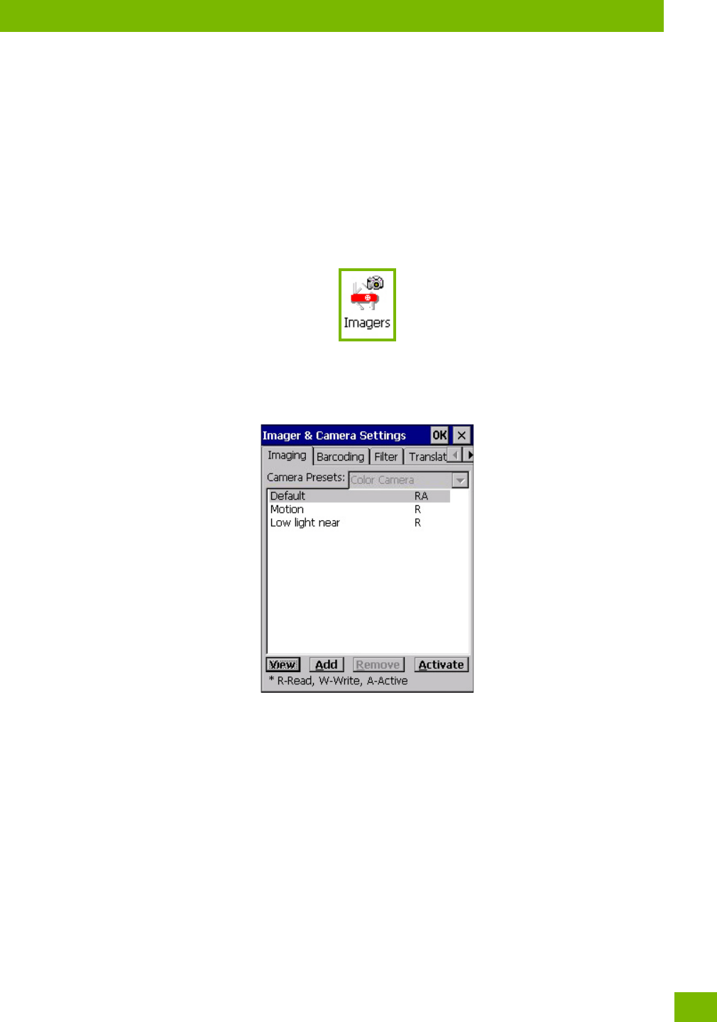
•Tap on the Imagers icon, and if it’s not already selected, tap on the Imaging tab.
The following screen is displayed.
Figure C.1 Imaging Menu
This window lists all the presets, both predefined and custom. Presets are identified as follows:
• Predefined presets are marked as ‘R’ read-only.
• Custom presets are marked as ‘RW’ read and write.
• One preset—either predefined or custom—is marked as ‘A’ active.
C.3.1.1 Selecting a Camera
To sele ct a cam era:
•Tap on the Camera Presets drop-down menu to view the camera options.
•Choose a camera—specifically, Front Imager which is located at the top of the unit.
C.3.1.2 Setting the Active Preset
An active preset has an A to the right. To set an active preset:
• Highlight the preset, and tap on the Activate button.
Appendix C: Imager & Camera Settings
Configuring the Image Capture Presets (Imaging Menu)
Psion 8516 Vehicle-Mount Computer User Manual
C-6
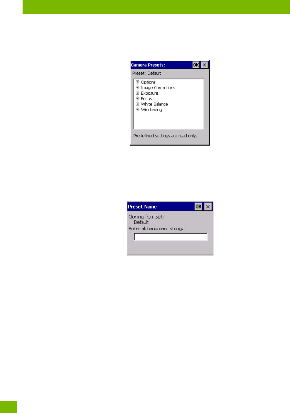
C.3.1.3 Viewing a Preset
To view the parameter settings in a preset:
• Highlight a preset, and double-tap on the View button.
The associated preset window is displayed.
• Tap on the + sign to expand the lists so that you can view the parameter settings.
C.3.1.4 Creating a Custom Preset
A new custom preset is created by modifying a preset—either a predefined preset or an existing custom
preset. To create a custom preset:
• Highlight a preset, and tap on the Add button.
A screen like the sample below is displayed.
• Type the name of the new preset in the dialog box.
•Tap on OK to save your changes.
The preset list is displayed; the new custom preset appears at the end of the list. It is marked as read and
write.
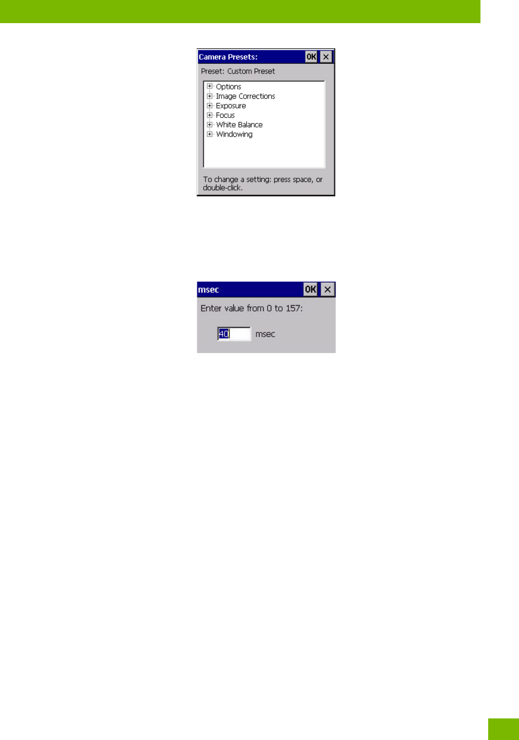
C.3.1.5 Modifying a Custom Preset
The parameter values in a custom preset can be modified. It is recommended that very few changes be
made to a custom preset. To ensure that it will work reliably, it should be as close as possible to the original
predefined preset. To change a parameter value:
• Highlight the custom preset, and double-tap on the Edit button.
Appendix C: Imager & Camera Settings
Configuring the Barcode Decoding Camera Presets (Barcoding Menu)
C-7
Psion 8516 Vehicle-Mount Computer User Manual
•Tap on the + symbols to expand the lists so that you can view the parameter settings.
• Scroll through the parameter list until you reach the parameter that you want to change.
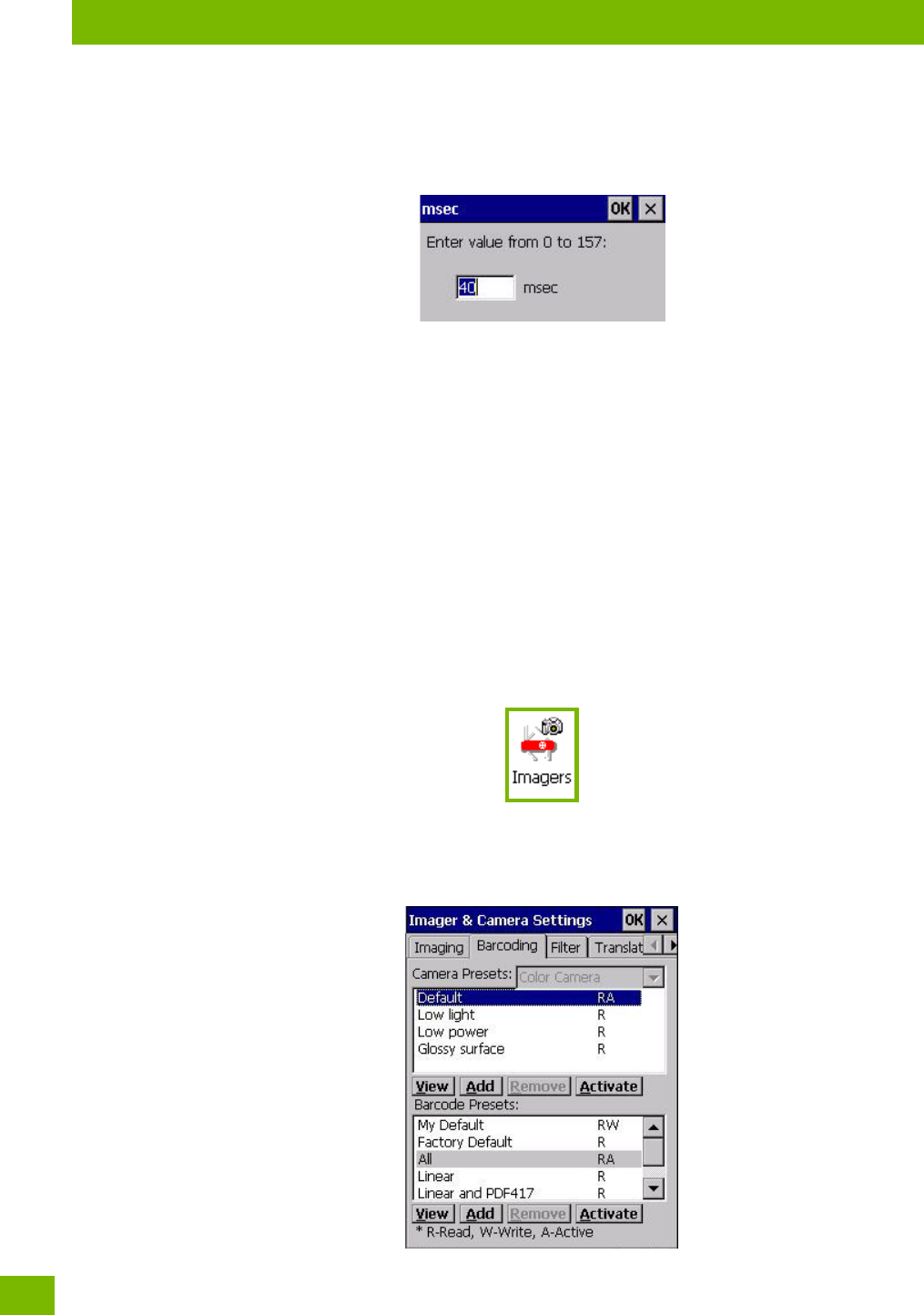
• For a parameter that can take a range of values:
- Highlight the parameter, and then press the [SPACE] key or double-click on the parameter.
- An associated dialog box containing the valid range of values for the parameter and the current
setting like the sample screen following is displayed.
- Type a value in the field provided.
• For a parameter that toggles between two values such as on or off and enabled or disabled:
- Highlight the parameter and then press the [SPACE] key, or double-click on the parameter. Either
method toggles between the two available values.
• When you’ve completed your edits, tap on OK.
The parameter list is displayed; the new value for the changed parameter is shown.
•Tap on OK to exit to the preset list and save the changes.
C.3.1.6 Removing a Custom Preset
• Highlight the custom preset you want to delete, and tap on the Remove button.
A window is displayed warning you that you are about to remove a preset.
•Tap on Ye s to remove the preset or No to cancel the operation.
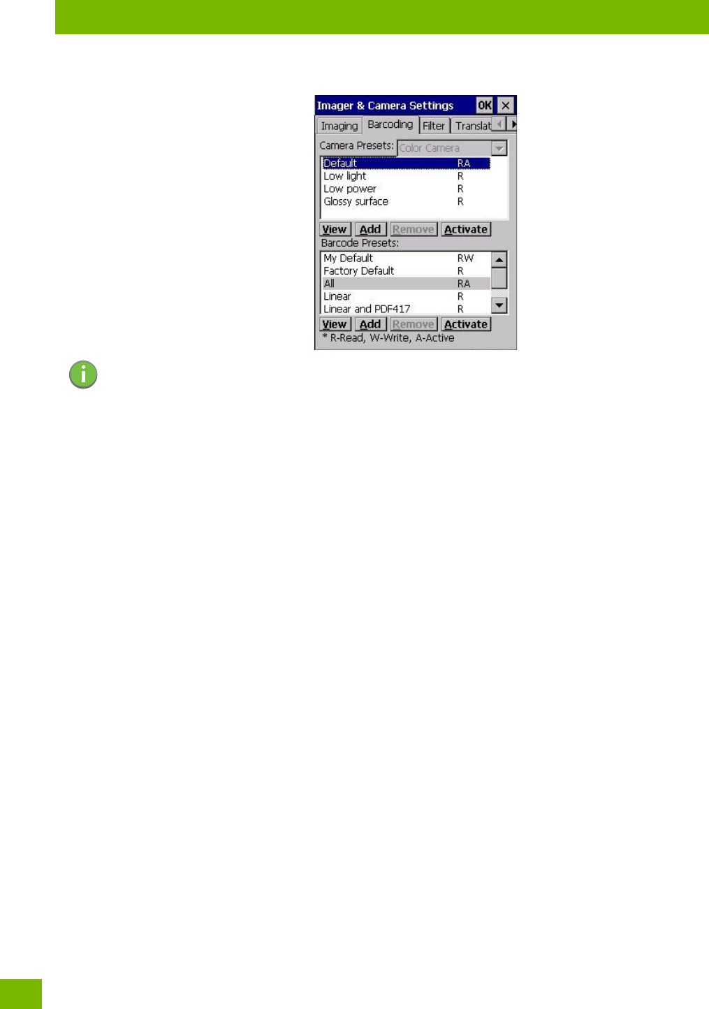
C.3.2 Configuring the Barcode Decoding Camera Presets (Barcoding Menu)
To configure the barcode decoding camera presets:
•Tap on Sta>Settings>Control Panel>Imagers.
•Tap on the Barcoding tab.
Appendix C: Imager & Camera Settings
Configuring the Barcode Decoding Camera Presets (Barcoding Menu)
Psion 8516 Vehicle-Mount Computer User Manual
C-8
Figure C.2 Camera Presets
This window lists all the presets, both predefined and the custom. Presets are identified as follows:
• Predefined presets are marked as read-only. For a description, review “Predefined Presets” on
page C-3.
• Predefined presets are marked as ‘R’ read-only.
• Custom presets are marked as ‘RW’ read and write.
• One preset—either predefined or custom—is marked as ‘A’ active.
C.3.2.1 Selecting a Camera
To select a camera:
• Tap on the Camera Presets drop-down menu to view the camera options.
•Choose a camera—specifically, Front Imager which is located at the top of the unit.
C.3.2.2 Setting the Active Preset
An active preset has an A to the right; in Figure C.3 on page C-10, the active preset is Default. To set an
active preset:
• Highlight the preset, and tap on the Activate button.
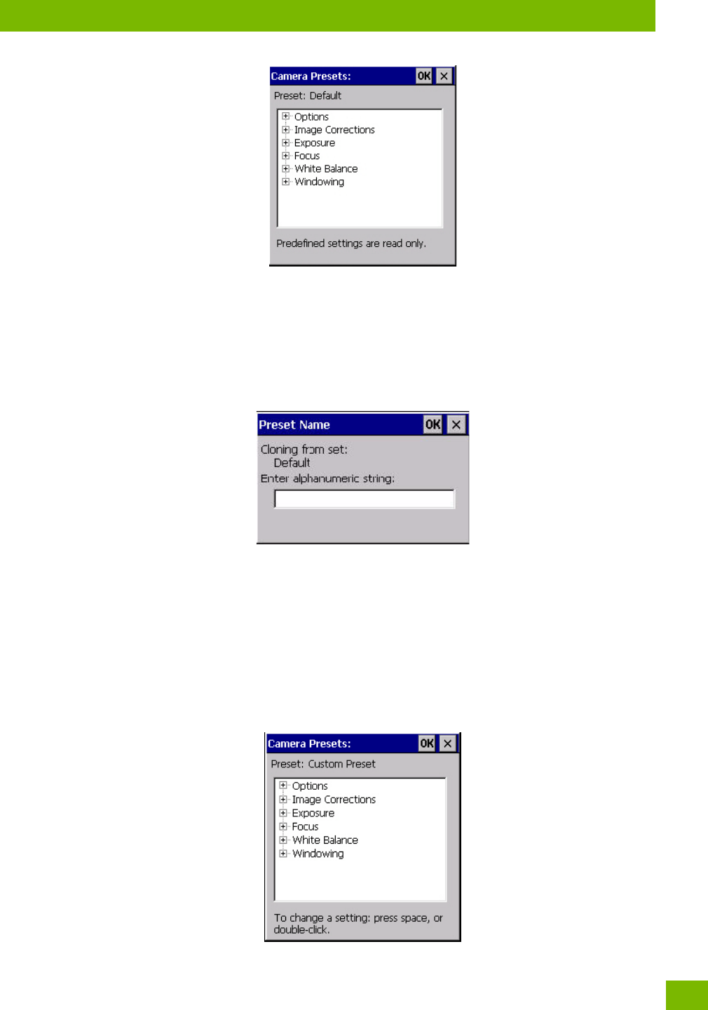
C.3.2.3 Viewing a Preset
To view the parameter settings in a preset:
• Highlight a preset, and double-tap on the View button.
The associated preset window is displayed.
Note: The top poion of the window displays the barcode decoding camera presets.
Appendix C: Imager & Camera Settings
Configuring the Barcode Decoding Camera Presets (Barcoding Menu)
C-9
Psion 8516 Vehicle-Mount Computer User Manual
•Tap on the + sign to expand one of the lists so that you can view the parameter settings.
C.3.2.4 Creating a Custom Preset
A new custom preset is created by modifying a preset—either a predefined preset or an existing custom
preset. To create a custom preset:
• Highlight a preset, and tap on the Add button.
A screen like the sample following is displayed.
•Type the name of the new preset in the dialog box.
•Tap on OK to save your changes.
The preset list is displayed; the new custom preset appears at the end of the list. It is marked as read and
write.
C.3.2.5 Modifying a Custom Preset
The parameter values in a custom preset can be modified. It is recommended that very few changes be
made to a custom preset. To ensure that it will work reliably, it should be as close as possible to the original
predefined preset. To change a parameter value:
• Highlight the custom preset, and double-tap on the Edit button.
•Tap on the + symbols to expand the lists and view the parameter settings.
Appendix C: Imager & Camera Settings
Configuring the Barcode Decoding Symbologies (Barcoding Menu)
Psion 8516 Vehicle-Mount Computer User Manual
C-10
• Scroll through the parameter list until you reach the parameter that you want to change.
• For a parameter that can take a range of values:
- Highlight the parameter, and then press the [SPACE] key or double-click the parameter.
- An associated dialog box containing the valid range of values for the parameter and the current
setting like the sample screen following is displayed.
- Type a value in the field provided.
• For a parameter that toggles between two values such as on or off and enabled or disabled:
- Highlight the parameter and then press the [SPACE] key, or double-click on the parameter. Either
method toggles between the two available values.
• When you’ve completed your edits, tap on OK.
The parameter list is displayed; the new value for the changed parameter is shown.
•Tap on OK to exit to the preset list and save the changes.
C.3.2.6 Removing a Custom Preset
• Highlight the custom preset you want to delete, and tap on the Remove button.
A window is displayed warning you that you are about to remove a preset.
•Tap on Ye s to remove the preset or No to cancel the operation.
C.3.3 Configuring the Barcode Decoding Symbologies (Barcoding Menu)
To configure the barcode decoding camera presets:
•Tap on Sta>Settings>Control Panel>Imagers.
• Tap on the Barcoding tab.
Figure C.3 Viewing Barcode Decoding Symbologies
Appendix C: Imager & Camera Settings
Configuring the Barcode Decoding Symbologies (Barcoding Menu)
C-11
Psion 8516 Vehicle-Mount Computer User Manual
C.3.3.1 Setting the Active Preset
An active preset has an A to the right; in Figure C.3 on page 10, the active preset is Default. To set an active
preset:
• Highlight the preset, and tap on the Activate button.
C.3.3.2 Viewing a Preset
To view the parameter settings in a preset:
• Highlight a preset, and double-tap on the View button.
The associated preset window is displayed.
• Tap on the + sign to expand one of the lists so that you can view the parameter settings.
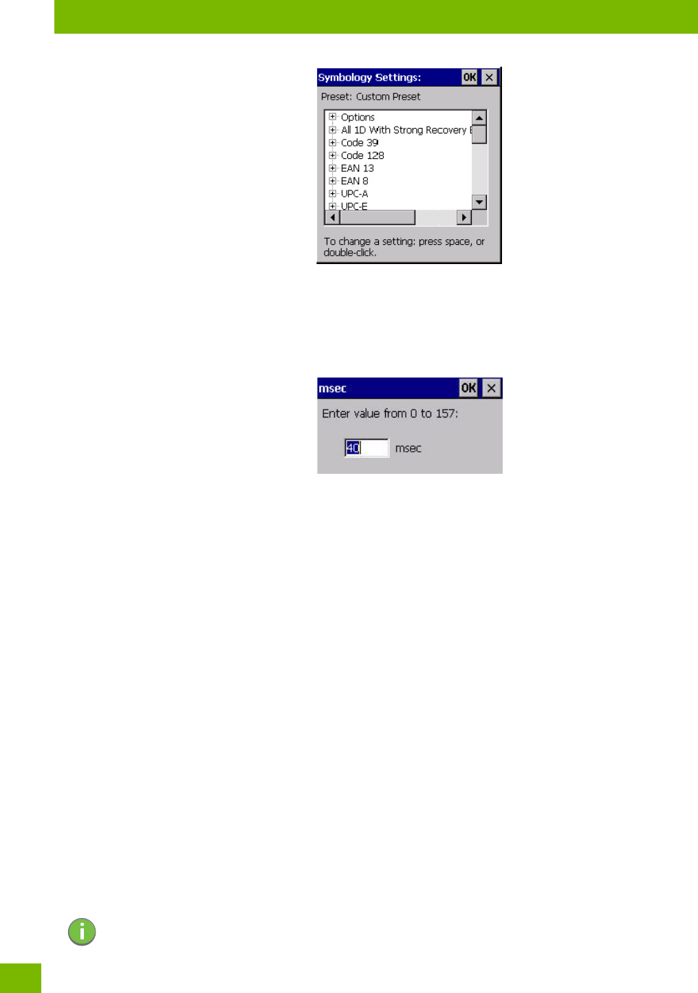
C.3.3.3 Creating a Custom Preset
A new custom preset is created by modifying a preset—either a predefined preset or an existing custom
preset. To create a custom preset:
• Highlight a preset, and tap on the Add button.
A screen like the sample following is displayed.
•Type the name of the new preset in the dialog box.
•Tap on OK to save your changes.
The preset list is displayed; the new custom preset appears at the end of the list. It is marked as read and
write.
C.3.3.4 Modifying a Custom Preset
The parameter values in a custom preset can be modified. It is recommended that very few changes be
made to a custom preset. To ensure that it will work reliably, it should be as close as possible to the original
predefined preset. To change a parameter value:
• Highlight the custom preset, and double-tap on the Edit button.
Note: The bottom poion of the window displays the barcode decoding barcode presets.
Appendix C: Imager & Camera Settings
Barcoding Menu – Configuring Symbologies
Psion 8516 Vehicle-Mount Computer User Manual
C-12
• Tap on the + symbols to expand the lists and view the parameter settings.
• Scroll through the parameter list until you reach the parameter that you want to change.
• For a parameter that can take a range of values:
- Highlight the parameter, and then press the [SPACE] key or double-click the parameter.
- An associated dialog box containing the valid range of values for the parameter and the current
setting like the sample screen following is displayed.
- Type a value in the field provided.
• For a parameter that toggles between two values such as on or off and enabled or disabled:
- Highlight the parameter and then press the [SPACE] key, or double-click on the parameter. Either
method toggles between the two available values.
• When you’ve completed your edits, tap on OK.
The parameter list is displayed; the new value for the changed parameter is shown.
•Tap on OK to exit to the preset list and save the changes.
C.3.3.5 Removing a Custom Preset
• Highlight the custom preset you want to delete, and tap on the Remove button.
A window is displayed warning you that you are about to remove a preset.
•Tap on Ye s to remove the preset or No to cancel the operation.
C.3.4 Barcoding Menu – Configuring Symbologies
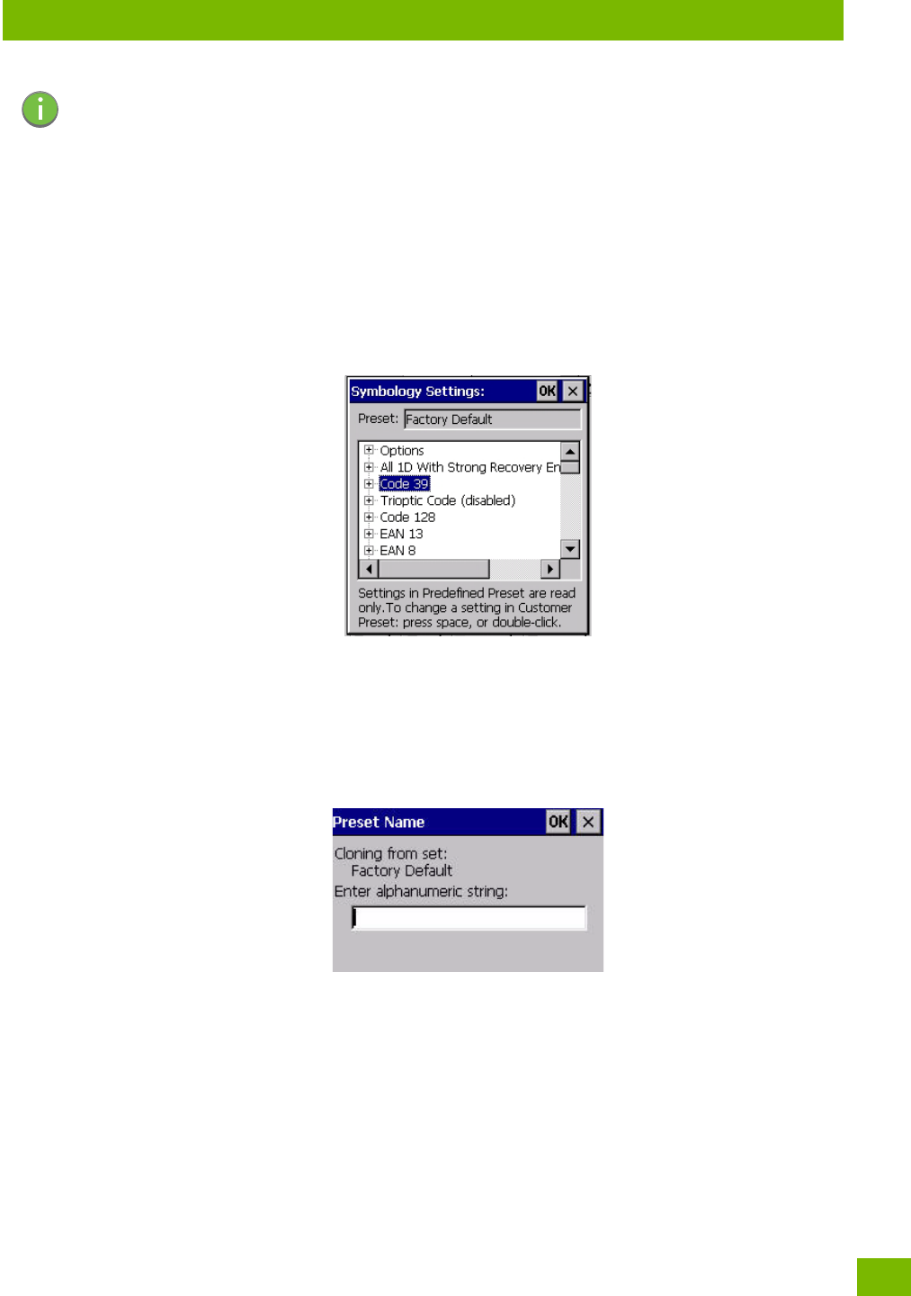
To v iew t he Symbology Settings options:
• Tap on the Barcoding tab, highlight All and then double-tap the View button.
To edit a default preset, you must first activate it:
•Tap on My Default, and tap on the Activate button – an A appears to the right of My Default.
Once the preset is activated, you can enable or disable the barcodes the imager will read.
• Highlight My Default in the Barcoding tab.
• Double-tap on the Edit button.
None of the other barcode decoding predefined presets are changed.
C.3.4.1 Symbology Settings
Note: For descriptions of the barcode symbologies, review “Barcode Symbologies” on
page C-15.
Appendix C: Imager & Camera Settings
Filter Menu – Manipulating Barcode Data
C-13
Psion 8516 Vehicle-Mount Computer User Manual
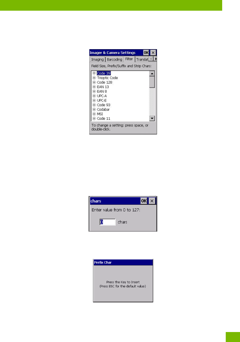
C.3.5 Filter Menu – Manipulating Barcode Data
To configure rules for manipulating barcode data:
•Tap on Sta>Settings>Control Panel.
•Tap on the Imagers icon, and then tap on the Filter tab.
C.3.5.1 Modifying a Barcode Setting
The rules for manipulating data from selected barcode symbologies can be modified. To change the set-
tings for a symbology:
•Tap on the + symbols to expand the lists and view the parameter settings.
• Scroll through the parameter list until you reach the parameter that you want to change.
• For a parameter that can take a range of values:
- Highlight the parameter, and then press the [SPACE] key or double-click the parameter.
- An associated dialog box containing the valid range of values for the parameter and the current
setting like the sample screen following is displayed.
- Type a value in the field provided.
• For a parameter that takes a single character:
- Highlight the parameter and then press the [SPACE] key, or double-click the parameter. The follow-
ing screen is displayed:
• When you’ve completed your edits, tap on OK.
Appendix C: Imager & Camera Settings
Translation Menu – Configuring Rules
Psion 8516 Vehicle-Mount Computer User Manual
C-14
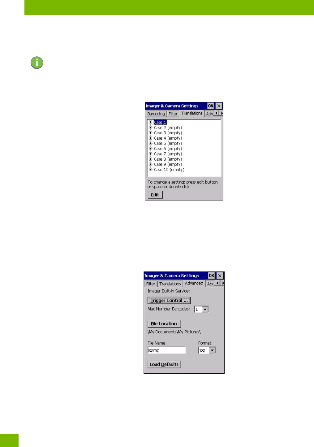
C.3.6 Translation Menu – Configuring Rules
Translation rules enable the automatic processing of barcode data. Up to 10 cases can be defined, each con-
sisting of up to 10 sequential rules.
•Tap on Sta>Settings>Control Panel.
• Tap on the Imagers icon, and then tap on the Translations tab.
For instructions on adding, editing, and removing translation rules, refer to “Translations” on page 89.
C.3.7 Advanced Menu
C.3.7.1 File Locations for Captured Images
To configure the location for saved images, open the dialog box as follows:
•Tap on Sta>Settings>Control Panel.
• Tap on the Imagers icon, and then tap on the Advanced tab.
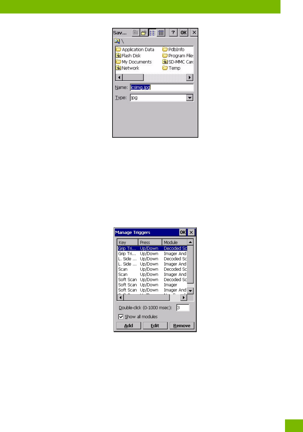
To define the location where imager files will be stored:
• Tap on the File Location button.
Note: Changes made to the translations configuration using the Scanner Control Panel program
are synchronized with changes made here. Changes made in either place affect both
translation tables.
Appendix C: Imager & Camera Settings
Barcode Symbologies
C-15
Psion 8516 Vehicle-Mount Computer User Manual
• Type the file Name, choose the Folder and file Typ e.
• Choose the Location in which your files will be saved.
• When you have completed all the changes, tap on the Save button.
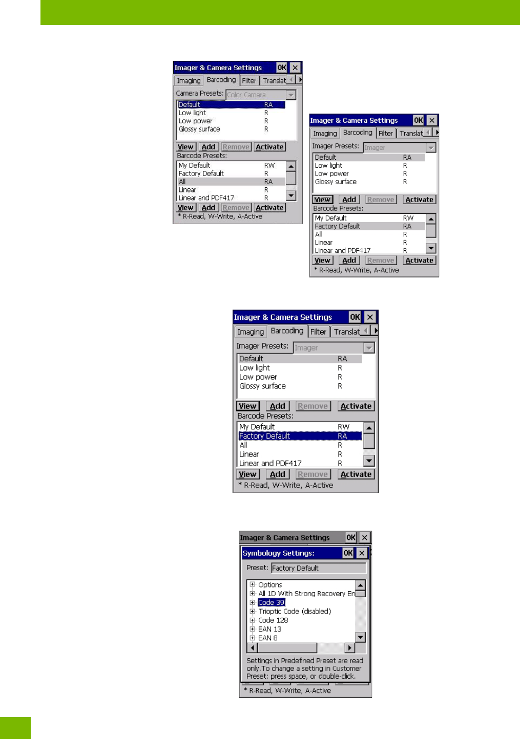
C.3.7.2 Configuring Triggers
Viewing the Trigger Configuration
The trigger on the 8516 is configured using the Manage Triggers applet. The Imagers applet provides a
shocut to the Manage Triggers applet.
•In the Advanced tab, tap on the Trigger Control button.
• To view all the triggers and the hardware devices that are configured to use them, tap in the checkbox
next to Show all modules.
Adding, Editing and Removing Triggers
For instruction about adding, editing and removing triggers, refer to “Manage Triggers” on page 71.
C.4 Barcode Symbologies
There are two sets of barcode symbologies, one for Imager and one for Color Camera. To display the bar-
codes available:
•In the Imager & Camera Settings screen, go to the Barcoding tab.
•In the Camera Presets: drop-down menu at the top of the Imager & Camera Settings screen, choose
Imager or Color Camera depending on which set of barcodes you want to work with.
Appendix C: Imager & Camera Settings
Barcode Symbologies
Psion 8516 Vehicle-Mount Computer User Manual
C-16
• Go to the Barcode Presets.
•Tap on an Barcode Preset to display the barcode symbologies.

Appendix C: Imager & Camera Settings
Imager Barcode Symbologies
C-17
Psion 8516 Vehicle-Mount Computer User Manual
C.4.1 Imager Barcode Symbologies
The barcode symbologies for the Imager are listed in this section.
Table C.1
Imager Barcode Symbologies
All 1D With Strong Recovery Enabled
Code 39
Code 128
EAN 13
EAN 8
UPC-E
UPC-A
UPC/EAN Sharing Settings
Code 93 (disabled)
MSI Plessey (disabled)
Code 11 (disabled)
Interleaved 2 of 5 (disabled)
Matrix 2 of 5 (disabled)
Discrete 2 f 5 (disabled)
Telepen (disabled)
Gs1 DataBar (disabled)
TLC-39 (disabled)
2D PDF-417
2D micro PDF-417
CodaBlock F (disabled)
CodaBlock A (disabled)
2D Data Matrix
2D QR Code
2D Maxicode (disabled)
2D Aztec (disabled)
Postal: PlanNET (disabled)
Postal: PostNET (disabled)
Postal: China (disabled)
Postal: Japanese (disabled)
Postal: Kix (disabled)
Postal: Royal (disabled)
Gs1

Appendix C: Imager & Camera Settings
Color Camera Barcode Symbologies
Psion 8516 Vehicle-Mount Computer User Manual
C-18
C.4.2 Color Camera Barcode Symbologies
The barcode symbologies for the Color Camera are listed in this section.
Table C.2
Color Camera Barcode Symbologies
All 1D With Strong Recovery Enabled
Code 39
Code 128
EAN 13
EAN 8
UPC-E
UPC-A
Code 93 (disabled)
Codabar
Interleaved 2 of 5 (disabled)
Gs1 DataBar (disabled)
Gs1 Composite
2D PDF-417
2D micro PDF-417
2D Data Matrix
2D QR Code
2D Maxicode (disabled)
2D Aztec (disabled)
Postal: PlanNET (disabled)
Postal: PostNET (disabled)
Postal: Australia (disabled)
Postal: Canadian (disabled)
Postal: Japanese (disabled)
Postal: Kix (disabled)
Postal: Korean (disabled)
Postal: Royal (disabled)

D-1
Psion 8516 Vehicle-Mount Computer User Manual
DAPPENDIX: SCANNER
SETTINGS
DScann er Setti ngs
D.1 Barcode Settings........................................................D-3
D.1.1 Scanner Options...................................................D-3
D.1.2 Restoring Default Settings.............................................D-3
D.2 Decoded (Internal) Scanners................................................ D-4
D.2.1 Options....................................................... D-4
D.2.2 Decoded (Internal) Advanced Options......................................D-5
D.2.3 Decoded (Internal) Data Options........................................ D-6
D.3 Decoded (HHP).........................................................D-7
D.4 Decoded (Intermec ISCP)...................................................D-7
D.4.1 Decoded (ISCP) Options..............................................D-7
D.4.2 Decoded (ISCP) Advanced Options....................................... D-8
D.5 Non-Decoded Scanners................................................... D-9
D.5.1 Options.......................................................D-10
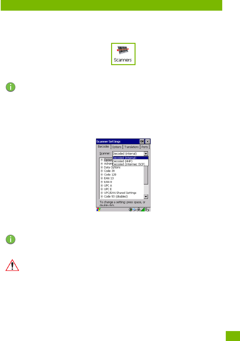
Appendix D: Scanner Settings
Barcode Settings
D-3
Psion 8516 Vehicle-Mount Computer User Manual
D.1 Barcode Settings
The Scanners icon in the Control Panel provides dialog boxes in which you can tailor barcode scanner con-
figurations and choose the barcodes your scanner will recognize.
The parameters are preset with the default settings of the decoded scanner installed in the unit. For a
listing of available scanners and their specifications, please refer to Chapter A: “8516 Specifications”.
D.1.1 Scanner Options
The drop-down menu to the right of the Scanner option allows you to choose configurations for one of the
following scanner types, depending on what is installed in/on your Vehicle-Mount: Decoded (internal),
Decoded (HHP), Decoded (Intermec ISCP, and Non-decoded Scanners.
The symbologies listed change to reflect the scanner you choose and the barcodes it suppos. Always defer
to your barcode scanner’s programming manual when in doubt about the availability or settings for any pa-
rameter.
Keep in mind that some barcode types are only available when an internal imaging scanner is installed. All
internal scanners can be configured using these dialog boxes.
D.1.2 Restoring Default Settings
If you want to restore the factory defaults after making changes, the defaults can be applied to a selected
parameter, sub-tree of parameters, or all scanner parameters.
• Press and hold on a symbology (e.g., Code 128) to display a pop up a menu.
Important: To enable a newly-installed scanner, press and hold down the [FN] key and the
[ENTER/Power] key simultaneously for a minimum of three seconds.
For information on configuring the Options, Translations, and Ports settings, see
“Scanners” on page 86.
Note: Your 8516 comes preconfigured from the factory for internal scanner types. The type of
scanner installed can be determined from the System icon in the Control Panel, under the
System Propeies tab.
Important: To improve the decode speed and performance, enable (set to ‘on’) only those
codes that are required by the application.
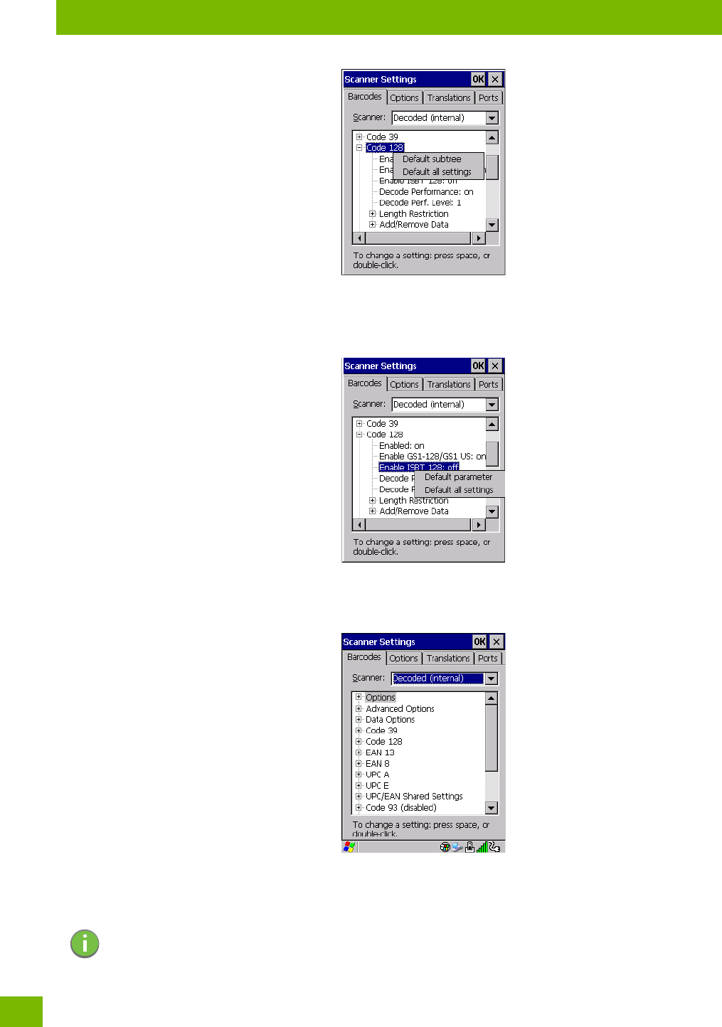
Appendix D: Scanner Settings
Decoded (Internal) Scanners
Psion 8516 Vehicle-Mount Computer User Manual
D-4
•Choose Default subtree to reset only the parameters in the symbology you selected, or choose
Default all settings to reset all scanner parameters to default settings.
To reset a single parameter to its default setting:
• Press and hold on the parameter you want to reset.
•Choose Default parameter to reset the parameter to the default setting.
D.2 Decoded (Internal) Scanners
• Tap on the Scanner drop-down menu, and choose Decoded (internal).
D.2.1 Options
Note: Some options are available only for specific scanners. Refer to the option names in this sec-
tion for scanner model identification.

Appendix D: Scanner Settings
Decoded (Internal) Advanced Options
D-5
Psion 8516 Vehicle-Mount Computer User Manual
Dot Time (msec)
The value selected for Dot Time (msec) determines (in milliseconds) how long the targeting dot remains on
before the scanner switches to a normal scan sweep. When you double-tap on this parameter, a dialog box
is displayed in which you can enter a value of 0 msec, 200 msec or 400 msec. A value of 0 (zero) disables
the target dot.
Laser On Time
The value assigned to this parameter determines how long the laser will remain on when the scan button or
trigger is pressed.
Double-tapping on this parameter displays a dialog box in which you can enter a value between 5 and 99.
The value is measured in tenths of seconds.
D.2.2 Decoded (Internal) Advanced Options
Scan Mode
You can set the method of scanning by setting this parameter to Scan beam only, Aim with Scan: 1 trigger
pull, Aim with Scan: 2 trigger pulls, Aim with Scan on trigger release, and Continuous Scan Mode. Default is
Scan beam only.
Aim Duration
This parameter determines the total time the aiming pattern appears before the scanner laser begins
sweeping. When you double-tap on this parameter, a dialog box is displayed in which you can enter a value
from 0 to 30 (0 to 3 sec.). A value of 0 (zero) disables the aiming-dot.
Minimum Cancel Time
The value assigned to this parameter determines the time delay before the scanner is turned off, once the
scanner trigger or button is released. This gives the scanner a minimum amount of time to complete its
current decode before the scan is cancelled when you quickly trigger on/off.
Power Mode
This parameter is a power-saving option. Tapping on it displays a screen listing two power mode options:
Continuous Power and Low Power.
In Continuous Power mode, the scanner is always on, waiting for a trigger pull or serial communication.
In Low Power mode, the scanner is in a suspend state, drawing minimal power until a trigger pull or serial
communication wakes it. Keep in mind that while this option is more suitable for battery powered applica-
tions, there will be a slight delay while the scanner powers up to scan a barcode.
Low Power Timeout
To eend laser life, you can select the time the scanner remains active following a successful decode. The
scanner wakes from low power mode when a barcode is scanned—a successful decode restores normal
flashing.
This is only used if the unit’s Trigger Mode has been changed to Continuous On. If the unit is used in a fixed
mount this parameter might be used, but not if the unit is used as a Vehicle-Mount.
When you double-tap on this parameter, a dialog box is displayed in which you can choose a value of 30
sec., 1 min., 2 min. or 3 min.
Parameter Scanning
Setting this parameter to on enables decoding of parameter barcodes.
Linear Security Level
This parameter allows you to select the security level appropriate for your barcode quality. There are four
levels of decode security for linear code types (e.g., Code 39, Interleaved 2 of 5). Higher security levels
Note: This parameter is only used if the Trigger Mode has been set to Continuous On and the 8516
is mounted in a fixed position; otherwise, ‘Low Power Timeout’ is not used.

Appendix D: Scanner Settings
Decoded (Internal) Data Options
Psion 8516 Vehicle-Mount Computer User Manual
D-6
should be selected for decreasing levels of barcode quality. As security levels increase, the scanner’s
decode speed decreases.
Double-tapping on this parameter displays a dialog box in which you can enter a value from 1 to 4.
Linear security level 1 specifies that the following code types must be successfully read twice before being
decoded:
Linear security level 2 specifies that all types of codes must be successfully read twice before being de-
coded.
Linear security level 3 specifies that code types other than the following must be successfully read twice
before being decoded. The following codes must be read three times:
Linear security level 4 requires that all code types be successfully read three times before being decoded.
Bi-Direction Redundancy
When this parameter is enabled, a barcode must be successfully scanned in both directions (forward and re-
verse) before being decoded.
D.2.3 Decoded (Internal) Data Options
Transmit Code ID Char
A code ID character identifies the scanned barcode type. In addition to any single character prefix already
selected, the code ID character is inseed between the prefix and the decoded symbol.
When you double-tap on this parameter, a dialog box is displayed in which you can choose a transmit code:
None, AIM or Symbol.
Scan Data Format
This parameter allows you to change the scan data transmission format.
Double-tapping on Scan Data Format displays the following options from which you can choose a data
format: data (as-is), data [S1], data [S2], data [S1][S2], [P] data, [P] data [S1], [P] data [S2] and
[P] data [S1][S2].
Prefix [P], Suffix [S1] and Suffix [S2]
A prefix and/or one or two suffixes may be appended to scan data for use in data editing. When you dou-
ble-tap on these parameters, dialog boxes are displayed in which you can enter a value from 0 to 255.
Code Type Length
Codabar All
MSI Plessey 4 or less
D 5 of 5 8 or less
I 2 of 5 8 or less
Code Type Length
MSI Plessey 4 or less
D 2 of 5 8 or less
I 2 of 5 8 or less
Note: This parameter is only valid if a “Linear Security Level” is enabled.
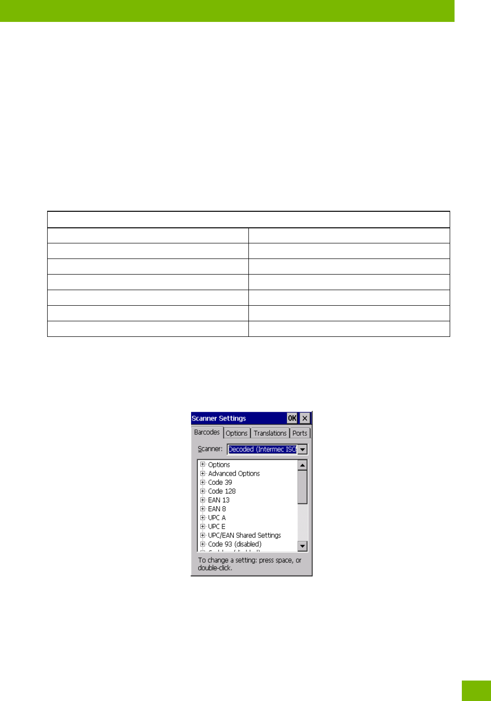
Appendix D: Scanner Settings
Decoded (HHP)
D-7
Psion 8516 Vehicle-Mount Computer User Manual
Delete Char Set ECIs
Setting this parameter to on enables the scanner to delete any escape sequences representing Character
Set ECIs (Eended Channel Interpretations [also known as GLIs]) from its buffer before transmission.
When this parameter is enabled, the scanner transmits data from PDF417 and MicroPDF417 barcodes con-
taining Character Set ECIs, even when the ECI Protocol is disabled.
ECI Decoder
Setting this parameter to on enables the scanner to interpret any Eended Channel Interpretations (ECIs)
suppoed by the scanner. This parameter has no effect on symbols that were not encoded using ECIs.
If this parameter is set to off and a symbol that was encoded using an ECI escape is scanned, the scanner
transmits the ECI escape followed by the uninterpreted data.
The barcode symbologies for the scanner are listed in Table D.1.
D.3 Decoded (HHP)
To configure imagers, please see Appendix C: “Imager & Camera Settings”.
D.4 Decoded (Intermec ISCP)
•Tap on the Scanner drop-down menu, and choose Decoded (Intermec ISCP).
D.4.1 Decoded (ISCP) Options
Laser On Time
The value assigned to this parameter determines how long the laser will remain on when the scan button or
trigger is pressed.
Table D.1
Decoded (Internal) Barcode Symbologies
Code 39 UPC/EAN Shared Settings
Trioptic Code (disabled) Code 93 (disabled)
Code 128 Codabar (disabled)
EAN 13 MSI Plessey (disabled)
EAN 8 Interleaved 2 of 5 (disabled)
UPC-A Discrete 2 f 5 (disabled)
UPC-E Gs1 DataBar (disabled)

Appendix D: Scanner Settings
Decoded (ISCP) Advanced Options
Psion 8516 Vehicle-Mount Computer User Manual
D-8
Double-tapping on this parameter displays a dialog box in which you can enter a value between 1 and 10
seconds.
D.4.2 Decoded (ISCP) Advanced Options
Continuous Scan Mode
Setting this parameter to on keeps the laser on and continuously decoding as long as the scanner button is
pressed and held down.
Minimum Cancel Time
The value assigned to this parameter determines the time delay before the scanner is turned off, once the
scanner trigger or button is released. This gives the scanner a minimum amount of time to complete its
current decode before the scan is cancelled when you quickly trigger on/off.
Low Power Timeout
To eend laser life, you can select the time the scanner remains active following a successful decode. The
scanner wakes from low power mode when a barcode is scanned—a successful decode restores normal
flashing.
When you double-tap on this parameter, a dialog box is displayed in which you can choose a value of 30 sec,
1 min, 2 min, or 3 min.
Parameter Scanning
Setting this parameter to Enabled allows decoding of parameter barcodes.
Same Read Validate
The data is only transmitted after repeated reads give the same result. The value assigned at this parame-
ter determines the number of reads required, from 0 to 10 times.
Same Read Timeout
Prevents the same barcode from being read more than once. The value assigned determines after what
time period the scanner will timeout, from 0 to 2550 msec.
Diff Read Timeout
Prevents unwanted reading of other barcodes on the same label. The value assigned determines after what
time period the scanner will timeout, from 0 to 2550 msec.
Add AIM ID Prefix
The AIM ID (Association for Automatic Identification and Mobility) is an international barcode identifier.
When this parameter is enabled, the AIM ID is inseed at the beginning of the decoded barcode.
Note: This parameter is only used if the Trigger Mode has been set to Continuous On and the unit
is mounted in a fixed position; otherwise, ‘Low Power Timeout’ is not used.
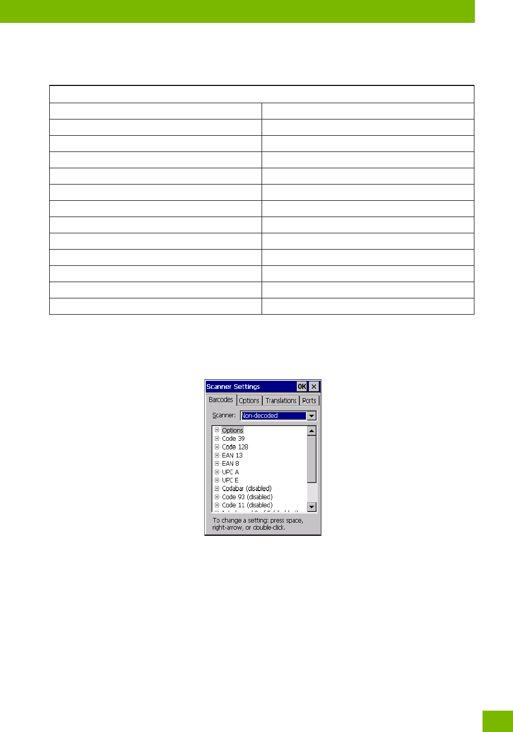
Appendix D: Scanner Settings
Non-Decoded Scanners
D-9
Psion 8516 Vehicle-Mount Computer User Manual
The barcode symbologies for the scanner are listed in Table D.2.
D.5 Non-Decoded Scanners
Figure D.1 Non-Decoded Scanner Options
•Tap on the Scanner drop-down menu, and choose Non-decoded.
All the available barcode symbologies for this type of scanner can be selected in this tab.
A ‘plus’ sign (+) to the left of the menu item indicates that a sub-menu of parameters is attached.
•Tap on the + sign to display the sub-menu.
• To change a parameter value, double-tap on the parameter. If you need to type a value, a dialog box is
displayed in which you can type a new value. If you need to change a yes or no value, double-tapping
on the parameter toggles between yes and no.
If you’re using the keyboard:
• Highlight the barcode you want to work with, and press the [RIGHT] arrow key to display the sub-menu.
• Use the [UP] and [DOWN] arrow keys to highlight a parameter.
• To change a parameter value, press [SPACE] or the [RIGHT] arrow key. If a field requires te entry, a te
box is displayed in which you can enter the appropriate value.
Table D.2
Decoded (Intermec ISCP) Barcode Symbologies
Code 39 TLC-39 (disabled)
Code 128 2D PDF-417
EAN 13 2D micro PDF-417
EAN 8 Discrete 2 of 5 (disabled)
UPC-A Telepen (disabled)
UPC-E Gs1 DataBar (disabled)
UPC/EAN Shared Settings Composite
Code 93 (disabled) TLC-39 (disabled)
Codabar (disabled) PDF-417
MSI Plessey (disabled) micro PDF-417 (disabled)
Code 11 (disabled) CodaBlock F (disabled)
Interleaved 2 of 5 (disabled) CodaBlock A (disabled)
Matrix 2 of 5 (disabled)

Appendix D: Scanner Settings
Options
Psion 8516 Vehicle-Mount Computer User Manual
D-10
D.5.1 Options
• Tap on the + sign next to Options to display these parameters.
Dot Time (msec)
The value selected for “Dot Time (msec)” determines (in milliseconds) how long the targeting dot remains
on before the scanner switches to a normal scan sweep. When you double-tap on this parameter, a dialog
box is displayed in which you can enter a value from 0 to 3000. A value of 0 (zero) disables the target dot.
Sho Code
When enabled, this parameter allows scanning of sho I 2 of 5 barcodes (2 characters). When disabled, these
sho barcodes are rejected.
Enabling “Sho Code” may reduce the robustness of the decoding since the Vehicle-Mount must decode
more potential barcodes; it is therefore not recommended for general-purpose barcodes with 4 or more
characters.
Verify
The value entered for this parameter determines the number of correct additional decodes required after
the initial decode, prior to a barcode being accepted. Higher values significantly increase the time it takes
to decode a barcode but also improve the reliability of the decoded barcode.
Security
This parameter controls the tolerance for decoding edge-to-edge barcodes (Code 93, Code 128, UPC/EAN).
Lower values have a lower tolerance for misreads, but they also increase the time it takes to decode the
barcode. The default value of 30 is generally a good compromise setting.
The barcode symbologies for the scanner are listed in Table D.3.
Table D.3
Non-Decoded Barcode Symbologies
Code 39 Code 93 (disabled)
Code 128 Code 11 (disabled)
EAN 13 Interleaved 2 of 5 (disabled)
EAN 8 MSI Plessey (disabled)
UPC-A Discrete 2 of 5 (disabled)
UPC-E IATA 2 of 5 (disabled)
Codabar (disabled)