Psion 8516 8516 Vehicle Mount Computer User Manual 8516 Vehicle Mount Computer
Psion Inc 8516 Vehicle Mount Computer 8516 Vehicle Mount Computer
Psion >
Contents
- 1. User Manual 1
- 2. User Manual 2
- 3. User Manual 3
User Manual 2

8516
VEHICLE-MOUNT COMPUTER
User Manual
(Windows® Embedded CE 6.0)
August 14, 2012
Pa No. 8000275.A
ISO 9001 Certified
Quality Management System

© Copyright 2012 by Psion Inc.
2100 Meadowvale Boulevard, Mississauga, Ontario, Canada L5N 7J9
http://www.psion.com
This document and the information it contains is the property of Psion Inc. This document is not to be used,
reproduced or copied, in whole or in part, except for the sole purpose of assisting in proper use of Psion
manufactured goods and services by their rightful owners and users. Any other use of this document is
prohibited.
Disclaimer
Every effort has been made to make this material complete, accurate, and up-to-date. In addition, changes
are periodically incorporated into new editions of the publication.
Psion Inc. reserves the right to make improvements and/or changes in the product(s) and/or the program(s)
described in this document without notice, and shall not be responsible for any damages including, but not
limited to, consequential damages, caused by reliance on the material presented.
Psion, the Psion logo, and the names of other products and services provided by Psion are trademarks of
Psion Inc.
Windows® and the Windows Logo are trademarks or registered trademarks of Microsoft Corporation in the
United States and/or other countries.
The Bluetooth® word mark and logos are owned by Bluetooth SIG, Inc. and any use of such marks by Psion
Inc. is under license.
All trademarks used herein are the property of their respective owners.
Return-To-Factory Warranty
Psion Inc. provides a return to factory warranty on this product for a period of twelve (12) months in accor-
dance with the Statement of Limited Warranty and Limitation of Liability provided at:
http://www.psion.com/us/warranty.htm
The warranty on Psion manufactured equipment does not extend to any product that has been tampered
with, altered, or repaired by any person other than an employee of an authorized Psion service organiza-
tion. See Psion terms and conditions of sale for full details.
Service and Information
Psion provides a complete range of product support services and information to its customers worldwide.
Services include technical support and product repairs. To locate your local support services, please go to:
www.psion.com/service-and-suppo.htm
To access further information on current and discontinued products, please go to our Teknet site and log in
or tap on “Not Registered?”, depending on whether you have previously registered for Teknet:
http://community.psion.com/support
A section of archived product information is also available online:
http://www.psion.com/products
Important: Psion warranties take effect on the date of shipment.

1
Psion 8516 Vehicle-Mount Computer User Manual
1INTRODUCTION
INTRODUCTION 1
1.1 About This Manual........................................................3
1.2 Text Conventions.........................................................3
1.3 Overview of the 8516 Vehicle-Mount Computer.......................................4

Chapter 1: Introduction
About This Manual
3
Psion 8516 Vehicle-Mount Computer User Manual
1.1 About This Manual
This User Manual describes how to configure, operate, and maintain the Psion 8516 Vehicle-Mount Compu-
ter.
Chapter 1: Introduction
provides a basic overview of the 8516.
Chapter 2: Basic Operation
describes the steps required to get the 8516 ready for operation.
Chapter 3: Getting To Know Your 8516
describes 8516 features, including how to charge and maintain the battery, the keyboard fea-
tures, the display, using the internal scanner, etc. Also describes the Microsoft® Windows®
Embedded CE 6.0 desktop and how to use it, and how to change the appearance and actions
of the desktop from Windows Classic Shell to the PsionVU Shell.
Chapter 4: Configuration
describes the Psion Software Advantage and Microsoft programs, and how to use them to
configure the 8516, along with scanners/imagers, Bluetooth, and so on. This chapter also
introduces you to the PsionVU program, which enables you to customize your computer set-
tings, remove or add shortcuts to the desktop and Control Panel, and lock down access to
various different components on the computer and the system tray icons for security. With
PsionVU and PsionVU Shell you can greatly enhance your User Experience.
Chapter 5: Accessories
describes the peripherals and accessories available for your 8516 computer.
Appendix A: 8516 Specifications
lists the specifications for your 8516 computer, radios, and battery.
Appendix B: Port Pinouts
describes the 8516 and accessories pinouts.
Appendix C: Imager & Camera Settings
details your imager options.
Appendix D: Scanner Settings
details your barcode options.
Appendix E: Wireless Wide Area Network (WWAN) Settings
describes WWAN configuration information.
Appendix F: Wireless Zero Config Settings
outlines the steps used to configure your radio using Windows Zero Config.
1.2 Text Conventions
Note: Notes highlight additional helpful information.
Important: These statements provide particularly important instructions or additional infor-
mation that is critical to the operation of the equipment.
Warning: These statements provide critical information that may prevent physical injury,
equipment damage or data loss.

Chapter 1: Introduction
Overview of the 8516 Vehicle-Mount Computer
Psion 8516 Vehicle-Mount Computer User Manual
4
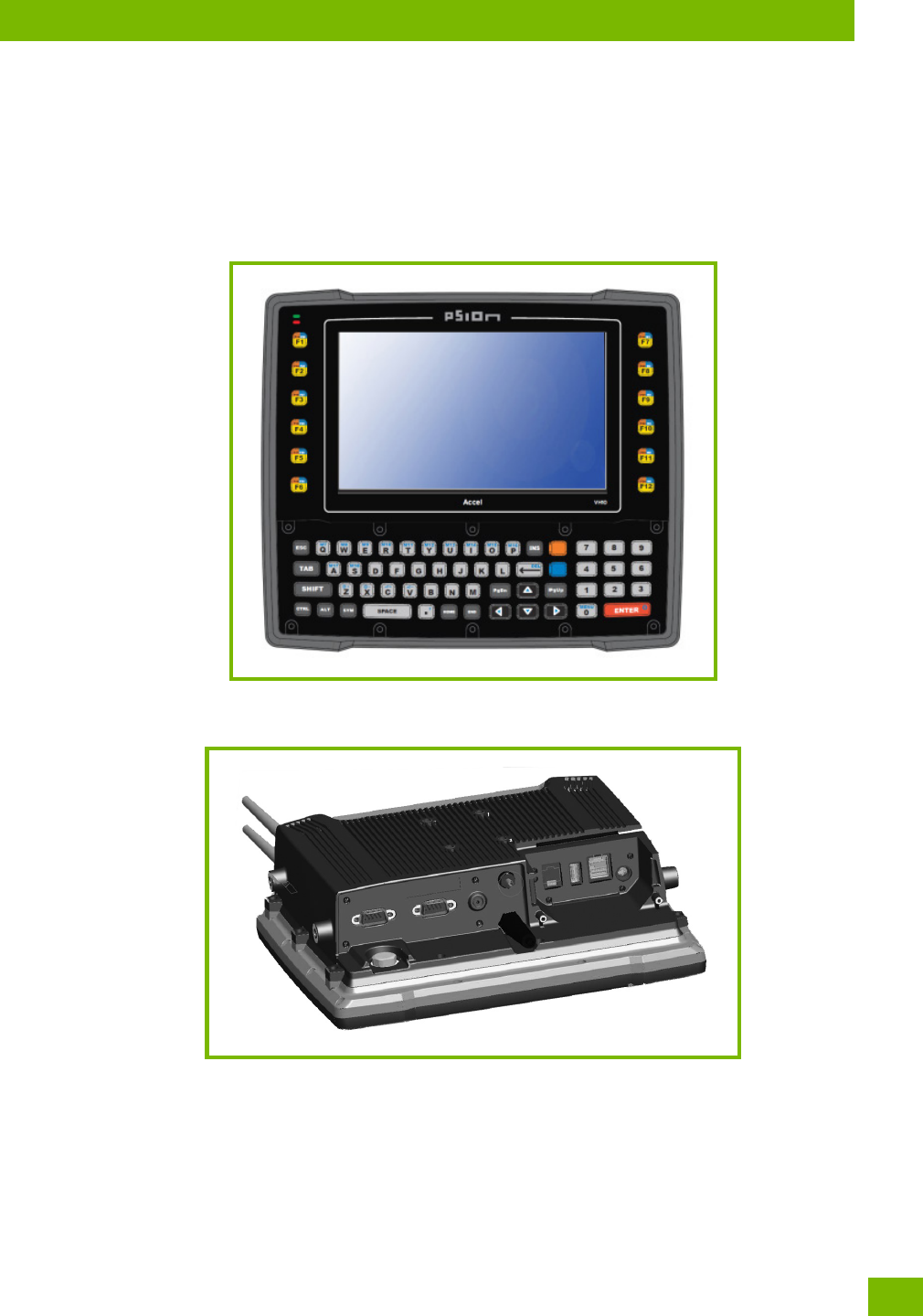
1.3 Overview of the 8516 Vehicle-Mount Computer
The 8516 is a modular, industrial vehicle-mounted computer, running the Microsoft Windows Embedded CE
6.0 operating system. It is intended for use in commercial and industrial applications with a focus on real
time wireless data transactions with options suiting materials handling applications in warehouses, manu-
facturing facilities, ports, and yards. A wide range of data input capabilities are supported through a variety
of imager, RFID and bar code scanner options.
Processor and Memory
•Texas Instruments
® OMAP3® Processor 800 MHz
•Flash ROM: 1 GB
•RAM: 512 MB
Operating System
•Microsoft
® Windows® Embedded CE 6.0
Bundled Applications
• Internet Explorer® 6
• Windows Mobile Device Center
•Wordpad
®, ActiveSync®
Supported Applications
•Psion TekTerm
• Stay-Linked Terminal Emulation
• Naurtech Browser
Device Management and Provisioning
•PsionVU
• Total Recall, TweakIt, Dr. Debug
• Mobile Control Centre (MCC)
- Easy configuration management and provisioning platform.
- Powerful remote control and troubleshooting functionality.
- Integrated real time geofancing and location services.
- Advanced device security, user authentication and lockdown features.
User Interface
• Colour/Touch Display 20.32 cm (8") diagonal
- VGA (800 x 480) Transflective
- High visibility option: superior sunlight visibility with 640 cd/m2 brightness
•Touchscreen
- Passive stylus or finger operation
- Optional heater
•Keyboard
- 67-key QWERTY and AZERTY available
- 12 dedicated function keys
- LED backlight
• Voice and Audio
- High volume beeper: 95 dBA
- Optional Push-to-Talk speaker/microphone
Note: For product specifications, refer to Appendix A: “8516 Specifications”.
Chapter 1: Introduction
Overview of the 8516 Vehicle-Mount Computer
5
Psion 8516 Vehicle-Mount Computer User Manual
Wireless Connectivity
• Model RA2070 802.11a/b/g/n Radio with Bluetooth® coexistence (Bluetooth V2.0 + EDR)
• Optional Model RA2047 802.11b/g Radio
The following figures illustrate the main features of the 8516 — for detailed views, please see “8516 Vehi-
cle-Mount Computer Features” on page 9.
Figure 1.1 8516 Front View
Figure 1.2 Bottom View

7
Psion 8516 Vehicle-Mount Computer User Manual
2BASIC OPERATION
BAS IC OPE RATIO N 2
2.1 8516 Vehicle-Mount Computer Features ...........................................9
2.2 Documents Available...................................................... 10
2.3 Preparing the 8516 for Operation.............................................. 10
2.3.1 8516 Safety Instructions.............................................. 10
2.3.2 The Internal Backup Battery............................................ 10
2.4 Switching the 8516 On and Off.................................................11
2.5 Resetting the 8516........................................................11
2.5.1 Performing a Warm Reset..............................................11
2.5.2 Performing a Cold Reset...............................................11
2.5.3 Performing a Clean Start ..............................................11
2.5.4 Boot to BooSt.....................................................11
2.6 Calibrating the Touchscreen................................................. 12
2.7 Connectivity........................................................... 12
Chapter 2: Basic Operation
8516 Vehicle-Mount Computer Features
9
Psion 8516 Vehicle-Mount Computer User Manual
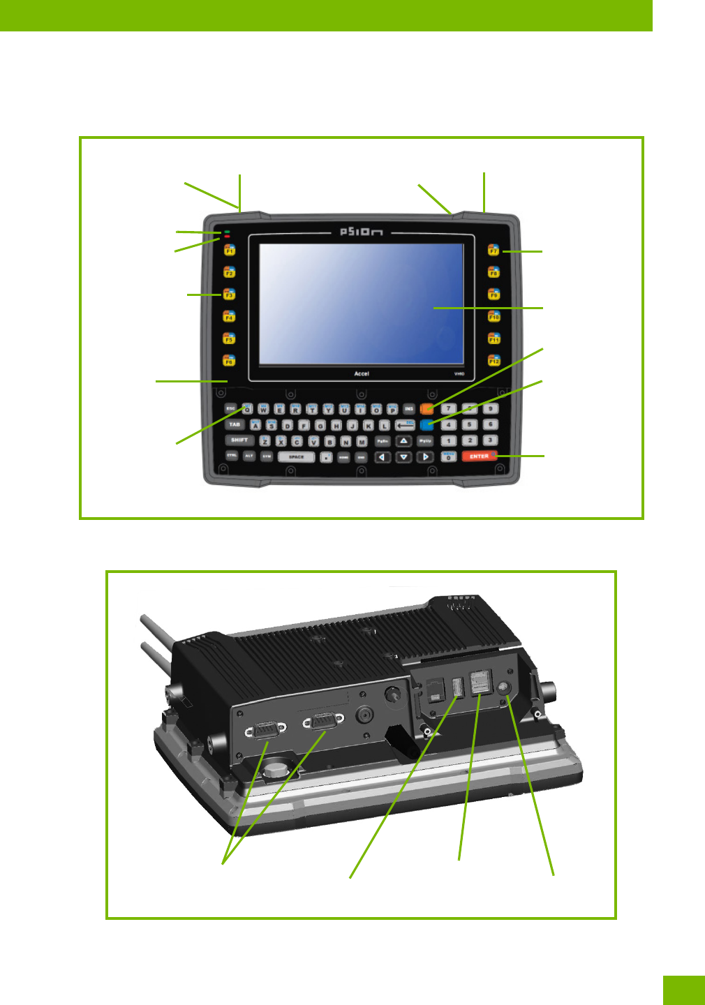
2.1 8516 Vehicle-Mount Computer Features
Figure 2.1 Front View
Figure 2.2 Bottom View
Display
Function keys
ENTER key
Macro keys
Antenna
Beeper
Function keys
Power LED
Radio LED
Power button
(behind antenna)
USB host port Antennas (2)
(inside dome plate)
FN key
SYM key
Audio jack
USB host port
UART RS-232 ports Powered USB host port

Chapter 2: Basic Operation
Documents Available
Psion 8516 Vehicle-Mount Computer User Manual
10
2.2 Documents Available
To see a current list of documents and download what you need, please go to the Knowledge Base on the
Psion Ingenuity Working community website:
http://community.psion.com/knowledge/w/knowledgebase/product-manuals.aspx
2.3 Preparing the 8516 for Operation
Typically the 8516 Vehicle-Mount Computer is configured at the factory and arrives ready for use. Although
the 8516 is equipped with an internal Compact Flash slot and a Micro-SD I/O slot, these slots are not in-
tended for user modification. If a device needs to be changed or added in these slots, contact qualified
Psion personnel.
2.3.1 8516 Safety Instructions
• The cord should be installed in the vehicle so that it is not subjected to damage or stress.
• Use of a power cord that is not recommended or sold by the manufacturer may result in fire, electric
shock, or personal injury.
• An extension cord should not be used unless absolutely necessary. Use of an improper extension cord
could result in fire or electric shock. If an extension cord must be used, make sure:
• The plug pins on the extension cord are the same number, size, and shape as those on the adaptor.
• The extension cord is properly wired and in good electrical condition and that the wire size is larger
than 16 AWG.
• When the unit is connected to the battery or AC adaptor, the mains power cord shall comply with
National safety regulations of the country where the equipment is to be used.
• Do not use the AC adaptor with a damaged cord or plug. Replace it immediately.
• Do not operate the AC adaptor if it has received a sharp blow, been dropped, or otherwise damaged in
any way; it should be inspected by qualified service personnel.
• Do not disassemble the AC adaptor; it should be repaired by qualified service personnel. Incorrect
reassembly may result in electric shock or fire.
• To reduce risk of electric shock, unplug the battery or AC adaptor from the outlet before attempting
any maintenance or cleaning.
• Do not expose the battery or AC adaptor to rain or snow.
2.3.2 The Internal Backup Battery
The 8516 Vehicle-Mount Computer is equipped with an internal battery that will provide backup power to
the unit for up to five minutes of normal operation. The display will be blank during this time. After five min-
utes, the unit will shut off to preserve the contents of RAM. The backup battery provides one week of
real-time clock backup. An optional internal 5000 mAh rechargeable battery is available for operation
during power loss or brown out.
The backup battery is not user accessible. It must be replaced by authorized Psion personnel.
Please see the following sections for detailed battery information:
• Calibration and power settings: “Power Properties” on page 75.
• Specifications: “Power Management” on page A-4.
The computer backup battery provides one hour of memory backup. The capacity is reduced as the operat-
ing temperature cools. Table 2.1: “Backup Battery Performance” on page 11 provides a general outline of
battery capacity based on the operating temperature. Charging of the backup battery will occur between
0° C and 40° C.
Warning: IT IS CRITICAL that this information be reviewed and that any guidelines appli-
cable to your 8516 be strictly followed.
Note: If the backup battery temperature is less than 10°C and a brown-out occurs, the display
backlight will switch off in order to maintain computer operations. The backlight will switch
back on when external power is restored or the battery temperature is above 10°C.

Chapter 2: Basic Operation
Switching the 8516 On and Off
11
Psion 8516 Vehicle-Mount Computer User Manual
2.4 Switching the 8516 On and Off
• To switch the 8516 on or off, press the Power button located on the top of the unit.
2.5 Resetting the 8516
To perform a warm or cold reset, you can access the menu by going to the Windows menu Start>Shutdown.
Alternatively you can use the keyboard shortcuts described below.
2.5.1 Performing a Warm Reset
During a warm reset, running programs are halted. The contents of the file system, RAM Disk, Flash Disk,
and the registry are preserved.
• Press and hold down the [FN] key and the Power button simultaneously for a minimum of
six seconds.
2.5.2 Performing a Cold Reset
A cold reset reinitializes all hardware. All RAM including the RAM Disk is erased. Non-volatile storage such
as the Flash Disk is preserved, as is the file system.
To execute a cold reset:
• Press and hold down the [SYM] key, the [FN] key, and the Power button, simultaneously for a
minimum of six seconds.
2.5.3 Performing a Clean Start
A clean start returns the 8516 to factory settings, flushes the registry keys, and deletes volatile storage and
the file system. The Flash Disk is preserved.
• Press and hold down the [FN] key, the Power button and the [ENTER] key simultaneously for a
minimum of six seconds.
The 8516 displays the Boot to BooSt menu.
•Type .clean.
2.5.4 Boot to BooSt
If you choose Boot to BooSt, the BooSt menu is loaded.
Table 2.1 Backup Battery Performance
Temperature Backup Battery Capacity
-20° C (-4° F) 65%
-10° C (14° F) 80%
0° C (32° F) close to 90%
Note: If the 8516 is in suspend state, pressing [ENTER] ‘wakes’ the unit from this state. The screen
in which you were working before the computer entered suspend state is displayed.
Note: If your Desktop is switched to the PsionVU Shell (refer to “The PsionVU Desktop Shell” on
page 31), resetting the unit is done solely by use of the keyboard shortcuts.
Note: You need to reset your 8516 after configuring the radio by switching between Windows Zero
Config and WiFi Config.
Note: As part of the normal Windows Embedded CE cold boot process, the screen may go blank for
a few seconds after the splash screen loading bar reaches the end. The desktop is displayed
after a few moments.

Chapter 2: Basic Operation
Calibrating the Touchscreen
Psion 8516 Vehicle-Mount Computer User Manual
12
•Press and hold down the [FN] key, the Power button and the [ENTER] key for a minimum of four
seconds.
•Press [1] to launch the OS.
2.6 Calibrating the Touchscreen
The 8516 touchscreen feature is factory-calibrated and ready-to-go; however, over time the touchscreen's
operating parameters may change, and it may need to be recalibrated for correct operation. Refer to “Cali-
brating the Touchscreen” on page 18 for details.
2.7 Connectivity
Data transfer options vary slightly depending on the type of operating system installed in your PC. Various
options exist depending on whether you are using Windows XP or earlier, Windows Vista® , Windows 7 or
later. For information on connecting the 8516 to a PC, please refer to “Data Transfer between 8516 and a
PC” on page 54.
The 8516 contains an integrated 802.11a/b/g/n radio module. The Wi-Fi Config application is used to config-
ure the radio for one or more wireless network profiles. To configure the radio, follow the steps outlined
under the heading “Wi-Fi Config” on page 109.
To configure your Bluetooth settings, please go to “Bluetooth® Setup” on page 44.
To see the radio specifications, please go to “Wireless Radios” on page A-5.
Note: The touchscreen function can be turned off (see “Touch” on page 95).

13
Psion 8516 Vehicle-Mount Computer User Manual
3GETTING TO KNOW YOUR
8516
GE TTING TO K NOW YOUR 85 16 3
3.1 Operating System........................................................ 15
3.2 The Keyboard.......................................................... 15
3.2.1 Regular Keys..................................................... 15
3.2.2.1 Activating Modifier Keys........................................ 17
3.2.2.2 Locking Modifier Keys.......................................... 17
3.2.2 Modifier Keys .................................................... 16
3.2.3 Function Keys and Macro Keys.......................................... 17
3.2.3.1 Function Keys .............................................. 17
3.2.3.2 Macro Keys................................................ 17
3.2.4 The Keypad Backlight................................................ 18
3.3 The Display ........................................................... 18
3.3.1 Adjusting the Display Backlight..........................................18
3.3.2 Calibrating the Touchscreen............................................ 18
3.4 Indicators ............................................................ 18
3.4.1 LEDs.......................................................... 18
3.4.1.1 Operating System Status LED..................................... 19
3.4.1.2 Radio Status LED............................................ 19
3.4.2 Onscreen Indicators................................................. 19
3.4.3 Audio Indicators...................................................20
3.5 Inserting the microSD Card and SIM Card ......................................... 21
3.5.1 Inserting the Cards................................................. 21
3.6 Scanners and Imagers.....................................................22
3.6.1 Basic Scanner Operations.............................................22
3.6.2 Scanning Techniques................................................22
3.6.3 Troubleshooting...................................................22
3.6.4 Operating One Dimensional (1D) Internal Laser Scanners...........................23
3.6.5 Operating Internal Two Dimensional (2D) Imagers...............................23
3.7 Windows Embedded CE 6.0..................................................24
3.7.1 Navigating in Windows Embedded CE and Applications............................24
3.7.1.1 Navigating Using a Touchscreen ...................................24
3.7.1.2 Navigating Using the Keyboard....................................24
3.7.2 The Windows Classic Shell Startup Desktop...................................25
3.7.2.1 The Taskbar ...............................................25
3.7.2.2 The Start Menu .............................................26
3.8 The PsionVU Desktop Shell.................................................. 31
3.8.1 Restoring the Windows Classic Shell.......................................33
3.9 General Maintenance......................................................33
3.9.1 Caring for the Touchscreen............................................33
3.9.2 Cleaning the 8516..................................................34
Chapter 3: Getting To Know Your 8516
Operating System
15
Psion 8516 Vehicle-Mount Computer User Manual
3.1 Operating System
•Microsoft
® Windows® Embedded CE 6.0
3.2 The Keyboard
The 8515 is available with an integrated keyboard in either QWERTY or AZERTY alphanumeric keyboard
layout. It features 67 keys, 12 direct function keys, and an LED backlight.
Most of the keys on the keyboard operate much like a desktop computer. Where a key or key function is not
consistent with the PC keyboard, those differences are described in the following sections.
There are a number of modifier keys that provide access to additional keys and system functions, as de-
scribed in “Modifier Keys” on page 16.
The blue [FN] modifier key provides access to additional keys and system functions. These functions are
colour coded in blue print above the keyboard keys.
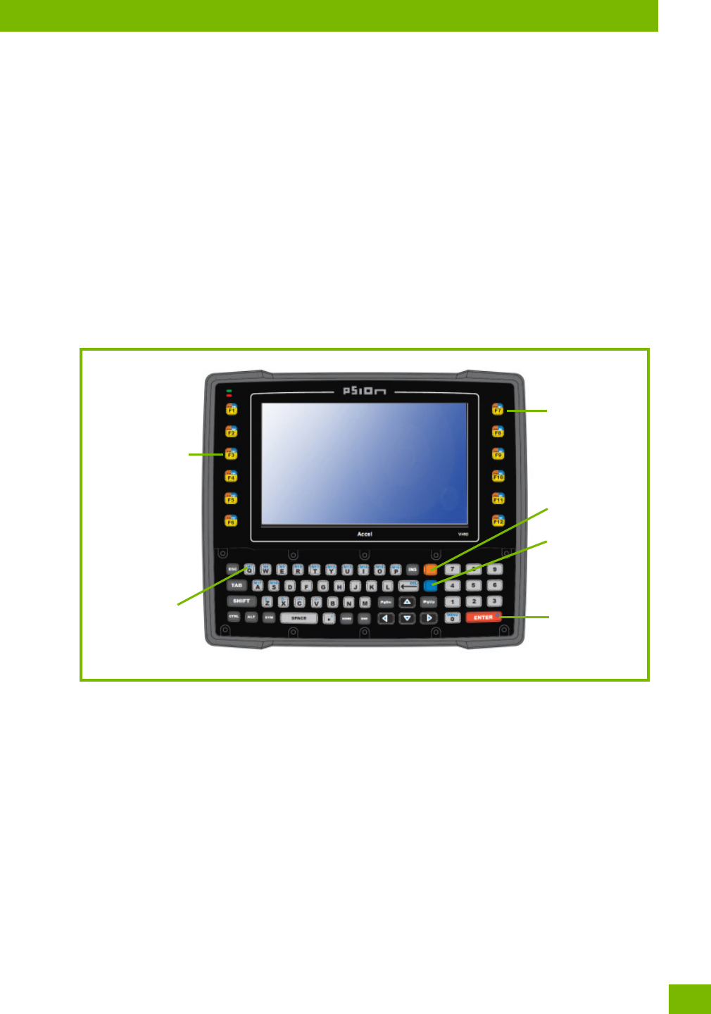
Figure 3.1 Keyboard Layout
3.2.1 Regular Keys
The Arrow Keys
The [Arrow] keys are located near the bottom of the keyboard, and are represented on the keyboard as tri-
angles pointing in different directions. The [Arrow] keys move the cursor around the screen in the direction
of the arrow: up, down, left and right. The left arrow key should not be confused with the backspace [DEL]
key which is depicted as a left arrow. The cursor is the flashing box or underline character that indicates
where the next character you type will appear.
The [DEL] Key
The [DEL] key (represented on the keyboard as an arrow pointing left) moves the cursor one character to
the left, erasing the previous key stroke.
The [FN] + [DEL]) erases the character at the current cursor position.
Function keys
ENTER key
Macro keys
Function keys
FN key
SYM key

Chapter 3: Getting To Know Your 8516
Modifier Keys
Psion 8516 Vehicle-Mount Computer User Manual
16
The [SHIFT/CAPS] Key
The [SHIFT/CAPS] key is used to display uppercase alpha characters. Pressing [FN][SHIFT] turns the [CAPS]
key on so that all alpha characters are printed in uppercase until the [FN][SHIFT] sequence is pressed
again.
The [CTRL] and [ALT] Key
The [CTRL] and [ALT] keys modify the function of the next key pressed and are application dependent.
Pressing either key twice locks it 'on' (it appears underlined on the Taskbar). Pressing the key once again
unlocks it.
The [TAB] Key
Typically, the [TAB] key moves the cursor to the next field to the right or downward.
The [ESC] Key
Generally, this key is used as a keyboard shortcut to close the current menu, dialog box, or activity.
The [SPACE] Key
Pressing this key inserts a blank space between characters. In a Windows dialog box, pressing the [SPACE]
key enables or disables a checkbox.
The [INS] Key
The [INS] key inserts a character at the cursor position.
The [SCAN] Key
The 8516 is equipped with a single [SCAN] key on the keyboard and an era [SCAN] button located on the
left side of the unit. [SCAN] keys activate the scanner beam. For units that do not have internal scanners,
these keys can be remapped to serve other functions.
3.2.2 Modifier Keys
The [SHIFT], [CTRL], [ALT], [FN] and [SYM] keys are modifier keys that change the function of the next key
pressed.
The [SHIFT], [CTRL] and [ALT] keys operate much like a desktop keyboard except that they are not chorded
(two keys held down simultaneously). The modifier key must be pressed first followed by the key whose
function you want modified.
[SHIFT] and [FN]
The [SHIFT] and [FN] modifier keys provide access to additional keys and system functions. The functions
related to these modifier keys are colour-coded in white and blue print respectively above the keyboard
keys, dependant on your keyboard format.
[SYM]
The Symbol [SYM] modifier key is represented on the keyboard by the characters ‘SYM’ and provides
access to commonly used symbolic characters. Pressing the key brings up the Symbol soft input panel (SIP)
onscreen keyboard, with symbols mapped to each key. If you wish to adjust the settings for the pop-up
screen (e.g. time of delay before screen appears, etc.), modify the file softinputpanel.xml, located in the
Windows folder.
The onscreen keyboard corresponds to the keyboard on your 8516.
Note: When using the Mobile Devices SDK Developers' Guide (PN 8100016), note that the [SYM]
key is interchangeable with the [ORANGE] key.
Note: Modifier keys are remapped in the Control Panel, and the Symbol SIP will automatically show
and use the new mappings after the next reboot.

Chapter 3: Getting To Know Your 8516
Function Keys and Macro Keys
17
Psion 8516 Vehicle-Mount Computer User Manual
3.2.2.1 Activating Modifier Keys
When a modifier key is pressed, it is shown in the softkey bar at the bottom of the screen, making it easier
to determine whether a modifier key is active. For example, if the [CTRL] key is pressed, Ctrl is displayed at
the bottom of the unit screen. Once the next key is pressed, the modifier key becomes inactive and disap-
pears from the taskbar.
3.2.2.2 Locking Modifier Keys
When a modifier key is pressed twice, it is ‘locked’ on. A ‘locked’ modifier key is displayed in underlined
letters in the taskbar. For example, pressing the [FN] key twice locks it on—it is displayed as an underlined
blue ‘FN’ in the taskbar at the bottom of the computer screen. The same is true of the [SYM] key, which is
shown as an underlined orange ‘SYM’ in the taskbar.
The locked modifier key will remain active until it is pressed a third time to unlock or turn it off. Once a mod-
ifier key is unlocked, the underline representation at the bottom of the screen is no longer displayed.
3.2.3 Function Keys and Macro Keys
In addition to the standard keyboard functions (see “The Keyboard” on page 15), the 8516 supports func-
tion keys and macro keys.
All function keys and macro keys can be custom defined for each application. The Open TekTerm applica-
tion utilizes these keys (for detailed information, see the Open TekTerm Software User Manual,
PN 8000073).
3.2.3.1 Function Keys
Function keys perform special, custom-defined functions within an application. These keys are accessed by
pressing one of the dedicated function keys on the keyboard, or through the appropriate [SHIFT] or [FN]
key sequence, depending on the keyboard variant being used.
Alphanumeric Keyboard Function Keys
The Alphanumeric keyboards are equipped with up to thirty function keys, including those function keys
that are colour-coded in blue print above the alpha keys or function keys (depending on your keyboard).
To access the blue function keys, press the [FN] key followed by the appropriate alpha or function key.
Function keys [F1] through [F24] can be used with the Windows Embedded CE operating system or another
application. The additional function keys, [F25] through [F30] along with the macros, are not used as pa of
the Windows Embedded CE operating system.
3.2.3.2 Macro Keys
Several of the 8516 keyboards are equipped with a series of macro keys that can be programmed to replace
frequently used keystrokes, along with the function of executable keys like the [ENTER] key, the [BACK-
SPACE] key, any function key and arrow key, etc.
59-Key Alphanumeric Keyboard Macro Keys
These keyboards have six macro keys: [M1] to [M6], located on the S to X keys (second-last row of keys).
To access a macro key, press the [FN] key followed by the macro key.
Note: The locking function of the modifier keys can be changed so that pressing a key once will
lock the key ‘on’.
If you disable the ‘One Shot’ function of the key, pressing it once will lock the key ‘on’. Press-
ing the same key a second time will unlock or turn it ‘off’. Refer to “Keyboard One Shot
Modes” on page 65 for details.
Important: Refer to “Keyboard Macro Keys” on page 65 for details about creating macros.
Chapter 3: Getting To Know Your 8516
The Keypad Backlight
Psion 8516 Vehicle-Mount Computer User Manual
18
3.2.4 The Keypad Backlight
The intensity of the keypad backlight and the conditions under which this backlight is activated can be con-
figured using the Keyboard icon in the Windows Embedded CE Control Panel. The behaviour of the keypad
backlight is tailored in the Keyboard Properties dialog box. Refer to “Keyboard Backlight” on page 64 for
details about this option.
3.3 The Display
The 8516 is equipped with display backlighting to improve character visibility in low light conditions. The
backlight switches on when a key is pressed.
3.3.1 Adjusting the Display Backlight
The behaviour of the display backlight and the intensity of the backlight can be specified in the Display
Properties dialog box in the Control Panel.
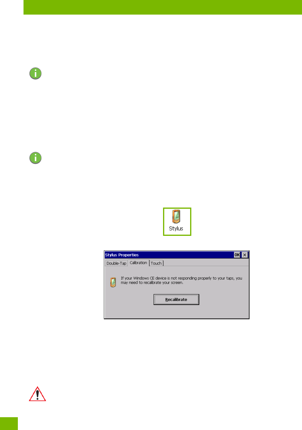
3.3.2 Calibrating the Touchscreen
If you find that the stylus pointer is not accurate when you tap on an item on the 8516 screen, use the
Stylus Properties dialog box in the Control Panel to recalibrate the screen.
•In the Control Panel, choose the Stylus icon to display the Stylus Properties window.
• Select the Calibration tab, and then choose the Recalibrate button.
• Follow the directions on the calibration screen to calibrate the screen.
3.4 Indicators
The 8516 uses LEDs (Light Emitting Diodes), onscreen messages, and audio tones as indicators.
3.4.1 LEDs
The 8516 is equipped with two coloured LEDs. This section outlines what these LEDs indicate.
Note: Keep in mind that this option may be restricted to supervisory use only.
Note: Refer to “Backlight” on page 55 for details about the Display Properties dialog box.
Important: If an LED is illuminated in red, the operator should be cautious as this generally
indicates an abnormal operating condition or active laser emission.
Chapter 3: Getting To Know Your 8516
Onscreen Indicators
19
Psion 8516 Vehicle-Mount Computer User Manual
Figure 3.2 LED Status Indicators
3.4.1.1 Operating System Status LED
The second LED indicates system notifications and operating system status. It is also available for
user-loaded custom Windows Embedded CE applications.
3.4.1.2 Radio Status LED
The third LED from the left indicates that the GPS radio is enabled or that the WWAN radio is enabled.
3.4.2 Onscreen Indicators
The taskbar at the bottom of the screen displays a variety of system status indicators, including the Input
Panel button if you have chosen to show that option in the Taskbar and Sta r t Menu settings.
2. Radio Status
1. Operating System Status
12
Tabl e 3.1
Operating LED Behaviour Function
OFF when unit is in Suspend or Shutdown. Normal operating status.
Solid Yellow The unit is powering on.
Fast Flashing Yellow The unit is entering Suspend mode.
Flashing Yellow This LED is controlled by the Microsoft NLED api.
Tabl e 3. 2
Radio Traffic LED Behaviour Function
OFF The radio is disabled.
Slow Flashing Blue The radio is enabled and active.
Chapter 3: Getting To Know Your 8516
Audio Indicators
Psion 8516 Vehicle-Mount Computer User Manual
20
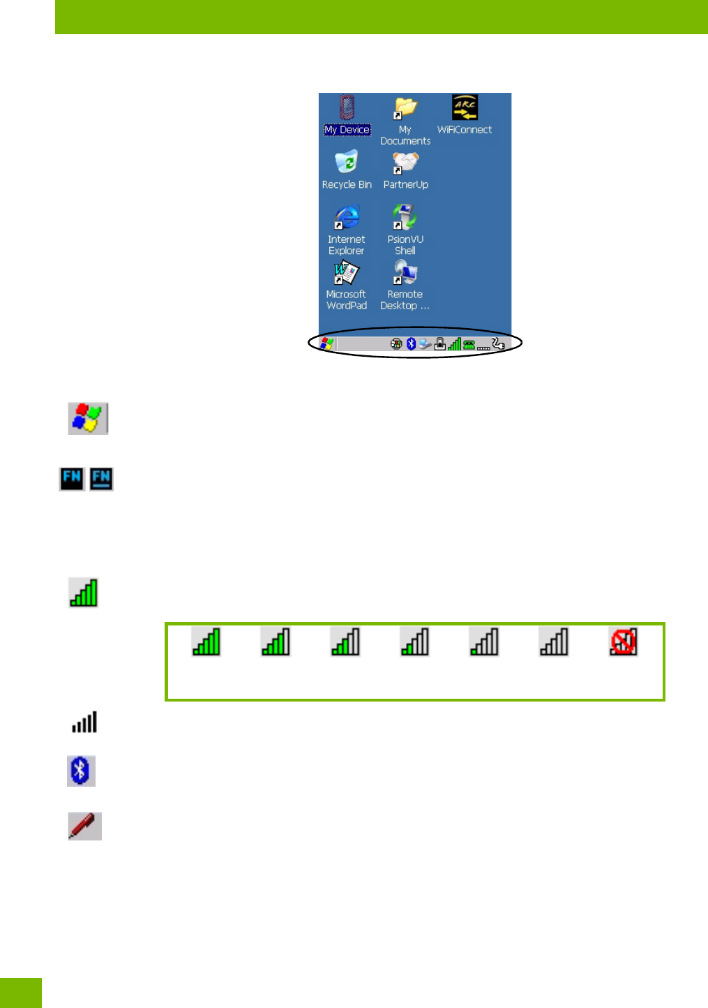
Figure 3.3 Taskbar
The taskbar changes dynamically, and only those icons that are applicable are displayed. For example, if a
radio is not installed in your 8516, the radio signal icon is not displayed in the taskbar.
Windows® Start Button
If you are using the touchscreen, you can either tap the Windows icon at the bottom left of the screen, or
press the [Windows] key to display the Start Menu, and then tap on the desired application.
Modifier Key Indicators
[SHIFT], [CTRL], [ALT], [FN] and [SYM] are modifier keys that have onscreen indicators to show when a key
is active or locked. If a modifier key is pressed once to activate it, the key is displayed in the taskbar, for ex-
ample, pressing the [FN] key once displays ‘FN’ in the taskbar. If a modifier key is pressed twice, it is ‘locked
on’ and the onscreen indicator is displayed with underlined letters in the taskbar, for example, pressing [FN]
twice displays ‘FN’ in the taskbar.
802.11 Radio Signal Quality
Increasing radio signal quality is represented by longer, filled bars within this icon.
WWAN Radio Signal Quality
Wireless WAN icons in the taskbar indicate the status of your wide area network connection. For details, see
“Taskbar Icons” on page E-3.
Bluetooth Radio
This icon displayed in the taskbar represents the installed Bluetooth radio.
Input Panel
You can tap the Input Panel icon to activate the soft keyboard application.
3.4.3 Audio Indicators
The 8516 supports several audio options, including Bluetooth. The optional rear speaker can be used for
system (Windows) sounds and .wav files. When a rear speaker is absent, those sounds are routed to the
front receiver. The beeper provides a variety of sounds and can be configured to emit a sound when a key is
pressed, a keyboard character is rejected, scan input is accepted or rejected, an operator’s entry does not
Good No Radio
Reception
Weak
Reception Link
Chapter 3: Getting To Know Your 8516
Inserting the microSD Card and SIM Card
21
Psion 8516 Vehicle-Mount Computer User Manual
match in a match field or the battery is low. The volume rocker button is located on the left side of the Vehi-
cle-Mount. Information on configuring sounds is detailed in “Volume & Sounds Properties” on page 108.
3.5 Inserting the microSD Card and SIM Card
There are two slots available in the battery compartment - the lower slot is provided for a microSD (Secure
Digital) card, which provides additional non-volatile memory to your 8516, and the upper slot is for a SIM
(Subscriber Identity Module) card, which allows access to the Voice option, access to the Internet, and so
on.
3.5.1 Inserting the Cards
• Switch off the power to the 8516.
• Remove the battery.
• Use a Phillips screwdriver to remove the SD cover screw. Flip the cover open or remove it.
For a microSD card:
• Slide the microSD card door to the left to unlock it. Flip it open.
• Slide the microSD card into the guides on the SD card door.
• Close the microSD card door, and slide it to the right to lock it.
For a SIM card:
• Slide the SIM card metal door latch to the right to unlock it, then flip the door open.
• Slide the card into the guides on the SIM card door.
• Swing the hinged door back down into place, and slide the metal door latch to the left to lock it.
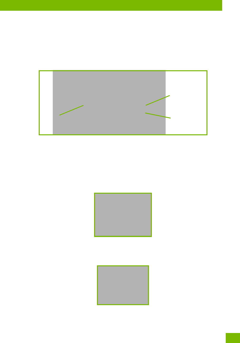
SD Cover
microSD Card Slot
SIM Card Slot

Chapter 3: Getting To Know Your 8516
Scanners and Imagers
Psion 8516 Vehicle-Mount Computer User Manual
22
3.6 Scanners and Imagers
The 8516 supports a wide range of scanner options to address a variety of user application requirements.
Refer to the following sections for detailed information:
• Configuration: “Scanners” on page 86 and “Manage Triggers” on page 71.
• “Scanning Techniques” on page 22 outlines the mechanics of a successful scan.
• Barcode Parameters: Appendix D: “Scanner Settings”.
• “Troubleshooting” on page 22 provides some helpful suggestions should the scan fail.
Scanner types include:
• Long Range: reads large 1D barcodes (55 mil) at long distances (up to 3m).
• Standard Range/High Performance: reads damaged or low contrast regular 1D barcodes (5 - 55mil) at
medium distances (up to 1m).
• Extended Range: reads regular 1D barcodes (5 - 55mil) at short to medium distances (1m), as well as
large 1D barcodes (e.g. 55 mil) at long distances.
• 1D Imager: reads regular 1D and PDF417 barcodes at short to medium distances.
• EA11 2D imager: reads 1D and 2D barcodes including damaged and low contrast regular 1D barcodes;
smallest barcode at 5 mil with a minimum read distance to 2.8 in. / maximum read distance of 5.1 in.;
largest barcode at 40 mil with a minimum read distance of 3.1 in. / maximum distance of 32.4 in.
• EA20X 2D imager: reads 1D and 2D barcodes including damaged and low contrast regular 1D barcodes;
shortest barcode at 6 mil with a minimum read distance of 6.1 inches / maximum read distance of 9.1
inches; longest barcode at 40 mil with a minimum read distance of 5.1 inches / maximum read distance
of 49.2 inches.
3.6.1 Basic Scanner Operations
• Turn the Vehicle-Mount on. Wait until the unit has booted up completely.
• Aim at the barcode and press the scan key or the trigger. A scan beam and a warning indicator appear
until a successful decode is achieved or six seconds have elapsed.
3.6.2 Scanning Techniques
• Hold the scanner at an angle. Do not hold it perpendicular to the barcode.
• Do not hold the scanner directly over the barcode. In this position, light can reflect back into the scan-
ner’s exit window and prevent a successful decode.
• Scan the entire barcode. If you are using a 1D or PDF laser scanner, make certain that the scan beam
crosses every bar and space on the barcode, including the margins on either end of the symbol.
• If you are using a 2D imaging scanner, make certain the red, oval shaped framing mark is centered
within the barcode you want to scan.
• When using imaging scanners, do not move the scanner while decoding the barcode. Movement blurs
the image.
• Hold the scanner farther away for larger barcodes.
• Hold the scanner closer for barcodes with bars that are close together.
3.6.3 Troubleshooting
If the scanner is not working, investigate the following:
• Is the unit on?
• Check that the barcode symbology being scanned is enabled for the Vehicle-Mount you are using.
Check any other parameters that affect the scanning procedure or the barcode.
• Check the barcode to make sure it is not damaged. Try scanning a different barcode to verify that the
problem is not with the barcode.
• Check that the barcode is within the proper range.
Important: It is critical that you review the “Laser Warnings” in the 8516 Vehicle-Mount
Computer Regulatory & Warranty Guide (PN 8000XXX) before using any of the
scanners described in this chapter.

Chapter 3: Getting To Know Your 8516
Operating One Dimensional (1D) Internal Laser Scanners
23
Psion 8516 Vehicle-Mount Computer User Manual
• Does the Vehicle-Mount display the warning without scanning? This suggests a hardware problem in
the Vehicle-Mount.
• Is the laser beam scanning across the barcode?
• Once the scan beam has stopped, check the scanner window for di or fogging.
3.6.4 Operating One Dimensional (1D) Internal Laser Scanners
• Turn the Vehicle-Mount on. Wait until the unit has booted up completely.
• Aim at the barcode and press the scan key or the trigger. A scan beam and a warning indicator appear
until a successful decode is achieved or six seconds have elapsed.
3.6.5 Operating Internal Two Dimensional (2D) Imagers
An imager scanner takes a snap shot of a single barcode or multiple barcodes (at one time). It can find a
barcode regardless of its orientation—that is, even a barcode printed at a 45 degree angle to the Vehi-
cle-Mount will be decoded successfully.
Because imager scanners generally have a shorter depth of field than laser scanners, some practise may be
required to find the optimal distance from the types of barcodes being scanned. Although the imager in-
cludes illumination LEDs, ambient light will help the imager decode the barcodes, especially if the barcode
is far from the Vehicle-Mount.
• Turn the Vehicle-Mount computer on. Wait until the unit has booted up completely.
• Aim at the barcode and press the scan key or the trigger. Hold the trigger until a successful or failed
scan result is obtained.
• When the scan button or trigger is pressed, a red, oval shaped light (the framing marker) is displayed.
Centre the framing marker in the field—either in the centre of the barcode you want to scan or in the
centre of the area in which multiple barcodes are to be scanned.
The illumination LEDs will flash (typically several times) and a picture of the barcode is taken.
Important: If an aiming dot is available on the installed scanner, the dot will be enabled for a
configurable time period (including off), after which normal scanning begins. Refer
to “Dot Time (msec)” on page D-5 for details.
Double-clicking the trigger will override the aiming delay and initiate an immedi-
ate scan. Note that the aiming dot is standard on long-range and high visibility
internal scanners.
Note: When scanning multiple barcodes, ensure that all of the desired barcodes are within the
field of view of the scanner. It is possible that even when all barcodes are within the field of
view, not all of them will be decoded. Only successfully decoded barcodes are passed to the
application program. The application program then issues a warning, asking that you scan
the missing barcodes.
When scanning a single barcode, ensure that only the desired barcode is within the field of
view of the scanner.
Important: Keep in mind that the imager scanner is a camera, and the LED illumination is a
flash. Glare can be an issue on reflective media such as plastic coated barcodes,
just as glare is an issue for photographers. When pointing at a shiny surface,
either shift the barcode to the side or top, or angle the barcode so that the glare
reflects away from the imager scanner.
Most imagers take several ‘snap shots’ of the barcode in order to decode it. It is
normal for the LEDs to flash two or three times. Hold the unit steady between
flashes to improve decode performance.

Chapter 3: Getting To Know Your 8516
Windows Embedded CE 6.0
Psion 8516 Vehicle-Mount Computer User Manual
24
3.7 Windows Embedded CE 6.0
3.7.1 Navigating in Windows Embedded CE and Applications
Graphic user interfaces like Windows Embedded CE for portable devices and desktop Windows (2000, XP,
etc.) utilize ‘point and click’ navigation. An equivalent keyboard shortcut is also available for every ‘point
and click’ action.
Windows Embedded CE supports the same ‘point and click’ user interface and keyboard shortcuts as
desktop Windows with one difference—the ‘point and click’ action is accomplished using a touchscreen
rather than a mouse. Actions can be performed using any combination of keyboard shortcuts or touch-
screen tapping. In those applications that support it, you can also flick and pan your finger to scroll through
screens.
3.7.1.1 Navigating Using a Touchscreen
The 8516 comes equipped with a stylus—a pointing tool that looks like a pen. The stylus is used to select
objects on the touchscreen. You can also use gestures with your fingers. You can use two gestures: pan and
flick. Use left or right flicks to quickly move between tabs of a multi-tab control panel, or to scroll long lists
of options. Use panning by touching and dragging a page that has scrollbars.
To choose an icon, open a file, launch an applet or open a folder:
• Double-tap on the appropriate icon.
3.7.1.2 Navigating Using the Keyboard
If you would like to use keyed input to choose icons and navigating dialog boxes, displaying the desktop you
can refer to Table 3.3 for a description of the navigation keys.
Keep in mind that unlike a desktop computer, the 8516 does not support key chording (pressing two keys at
the same time). You must press one key followed by the next in sequence.
Note: If the touchscreen is not registering your screen taps accurately, the touchscreen may need
recalibration. Refer to “Calibrating the Touchscreen” on page 18.
Note: To prevent damage to the touchscreen, use only a finger touch or the stylus (pen) supplied
with your 8516.
Table 3.3 Keyboard Navigation
Operation Key or Key Combination
Switch between active applications [ALT] [TAB]
Open task manager [ALT] [ESC]
Move the cursor Arrow keys
Open file, folder or icon [ENTER]
Exit & Save [ENTER]
Close/Exit & Do Not Save [ESC]
Navigate Dialog Boxes [TAB]
To move cursor up [SHIFT] [TAB]
To display the contents of the next ‘tab’ in a dialog box
[CTRL] [TAB]
Select Radio Button/Press Button [SPACE]
Go to Start Menu [Windows]
Chapter 3: Getting To Know Your 8516
The Windows Classic Shell Startup Desktop
25
Psion 8516 Vehicle-Mount Computer User Manual
3.7.2 The Windows Classic Shell Startup Desktop
When the 8516 boots up, the default startup desktop (Windows Classic Shell) is displayed. Any applications
stored in the Startup folder start up immediately.
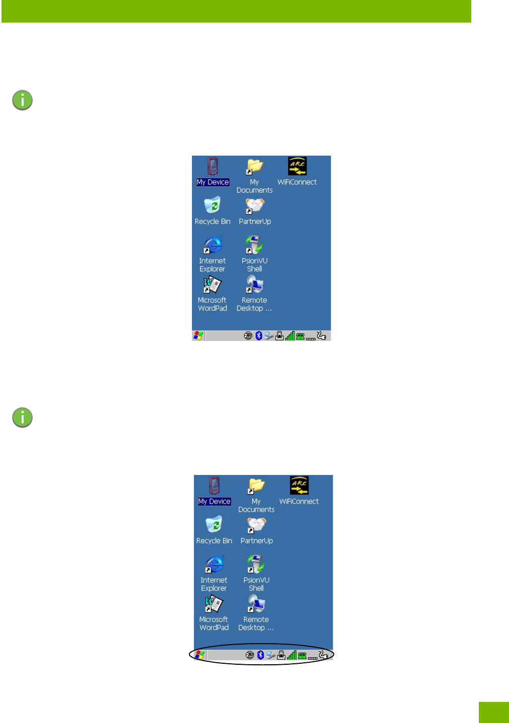
Figure 3.4 8516 Windows Classic Shell Startup Desktop
To access desktop icons:
• Double-tap on the icon to open a window or, in the case of an application icon, launch an application.
On the keyboard:
• Use the arrow keys to highlight the icon, and press [ENTER] to launch the highlighted icon.
3.7.2.1 The Taskbar
Note: The startup folder is located in \Windows\StartUp and \Flash Disk\StartUp.
Note: If the arrow keys do not highlight the desktop icons, the desktop may not be selected. Press
[Windows] to display the Start Menu, and select Desktop. Now the desktop will be “in focus”
and the arrow keys will highlight the icons.
Chapter 3: Getting To Know Your 8516
The Windows Classic Shell Startup Desktop
Psion 8516 Vehicle-Mount Computer User Manual
26
The 8516 is equipped with a taskbar at the bottom of the screen. It displays icons through which you can
view the battery capacity and radio signal quality of your unit. In addition, the taskbar displays the applica-
tion(s) currently running on your unit.
The taskbar also displays active modifier keys: [SHIFT], [ALT], [CTRL], [FN] and [SYM]. Keys that have been
locked “on” are displayed with underlined letters. For example, if you have set the [CTRL] key lock to “on” in
the Keyboard menu and you press the key, it is displayed as an underlined ‘Ctrl’ in the taskbar. (For detailed
information on modifier keys and keyboard options, see “The Keyboard” on page 15).
3.7.2.1.1 Using the Taskbar
A tooltip is displayed as each taskbar icon is highlighted. The tooltip provides the status of each icon.
If you’re using the touchscreen:
• Tap and hold on an icon to display the icon's tooltip. Double-tap the icon to open the Control Panel
dialog box associated with the icon. For example, double-tap the battery icon to display a dialog box
listing the current battery capacity information.
On the keyboard:
•Press [Windows] to display the Start Menu.
•Choose Shortcuts from the Start Menu, and then press the [RIGHT] arrow key to display the
sub-menu.
•Choose System Tray in the sub-menu.
• Use the arrow keys to highlight the icon in the taskbar about which you’d like more information.
•Press [ENTER] to display the appropriate dialog box.
3.7.2.1.2 Customizing the Taskbar
To customize the taskbar so that it displays only those icons you require:
•In the Start Menu, choose Settings, and then Ta s kb a r .
If you’re using the keyboard:
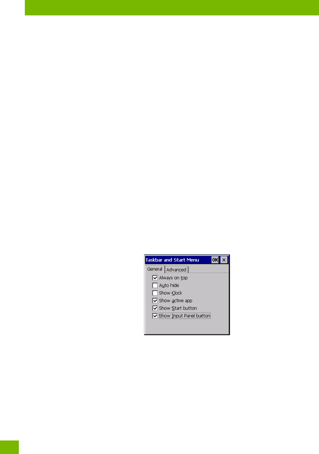
•Press [Windows] to display the Start Menu.
• Highlight the Settings option, highlight Ta sk b a r in the sub-menu, and press [ENTER].
The Task bar a nd Start M e n u dialog box is displayed.
• Tap on the items you want to activate or deactivate. The check mark indicates active items.
If you’re using the keyboard:
• Highlight the options you want to activate, and press the [SPACE] key to select them. A check mark
indicates active items.
3.7.2.2 The Start Menu
The Start Menu lists the operations you can access and work with. It is available from the startup desktop or
from within any application.
• To display the menu, tap on the Start Menu.
Chapter 3: Getting To Know Your 8516
The Windows Classic Shell Startup Desktop
27
Psion 8516 Vehicle-Mount Computer User Manual
If you’re using the keyboard:
• Use the arrow keys to highlight a menu item, and press [ENTER], or
If the menu item has an underlined character:
• Type the underlined alpha character. For example, to display the Run dialog box, type the letter ‘r’.
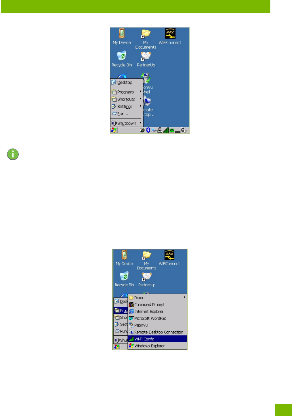
3.7.2.2.1 Programs
•Choose Programs to display a sub-menu of options. The programs displayed will be those resident in
the Windows\Programs folder of the computer.
Figure 3.5 Program Sub-Menu
This sub-menu allows you to choose Command Prompt, Internet Explorer, installed applications (e.g., Micro-
soft WordPad), PsionVU Access, Remote Desktop Connection, Wi-Fi Config, or Windows Explorer.
Demo
This folder contains the Scanner Demo, Demo Signature and Demo Sound applications. Scanner Demo can
be used to test how the Vehicle-Mount reads and writes barcodes. Demo Signature allows you to capture a
signature written on the screen with your stylus and save it to a file. Demo Sound allows you to record and
Note: Tap on the item in the menu with which you want to work.
Chapter 3: Getting To Know Your 8516
The Windows Classic Shell Startup Desktop
Psion 8516 Vehicle-Mount Computer User Manual
28
playback sound files. The ‘Sample Rate’ and the ‘Bits Per Sample’ are the rates at which the sound will be
recorded. Sounds recorded at the higher sample rate or bits per sample will be higher quality sound but will
require more file storage space. Lower sample rates and/or bits per sample produces a smaller file, but the
sound quality suffers. The record and play buttons operate the same as any recording device. The X icon
deletes the sound and the diskette icon allows you to save your sound.
Command Prompt
Command Prompt is used to access the DOS command prompt. At the prompt, you can type DOS com-
mands such as dir to display all the directories in the drive.
Internet Explorer
The 8516 is equipped with Microsoft Internet Explorer for Windows Embedded CE. You can access the Inter-
net Options icon through the Start Menu under Settings>Control Panel or by double-tapping on the desktop
icon My Device and then, double-tapping on the Control Panel icon.
Microsoft WordPad
WordPad is a basic word processor used to create, edit, and print .f, .doc, and .t files.
PsionVU Access
PsionVU Access allows you to change the appearance and actions of the desktop from the default Windows
Classic Shell to the PsionVU shell.
Remote Desktop Connection
Remote Desktop Connection is an 8516 application used to connect to a Windows Terminal Server so that
you can run a “session” on the Server machine using the Vehicle-Mount (Windows Embedded CE device).
“Remote Desktop Connection” on page 85 provides a website with details about this option.
Wi-Fi Config
The Wi-Fi Config application is used to configure the 8516 802.11a/b/g/n radio for one or more wireless
network profiles.
Windows Explorer
The Windows Explorer installed on your 8516 is consistent with all Windows Embedded CE devices.
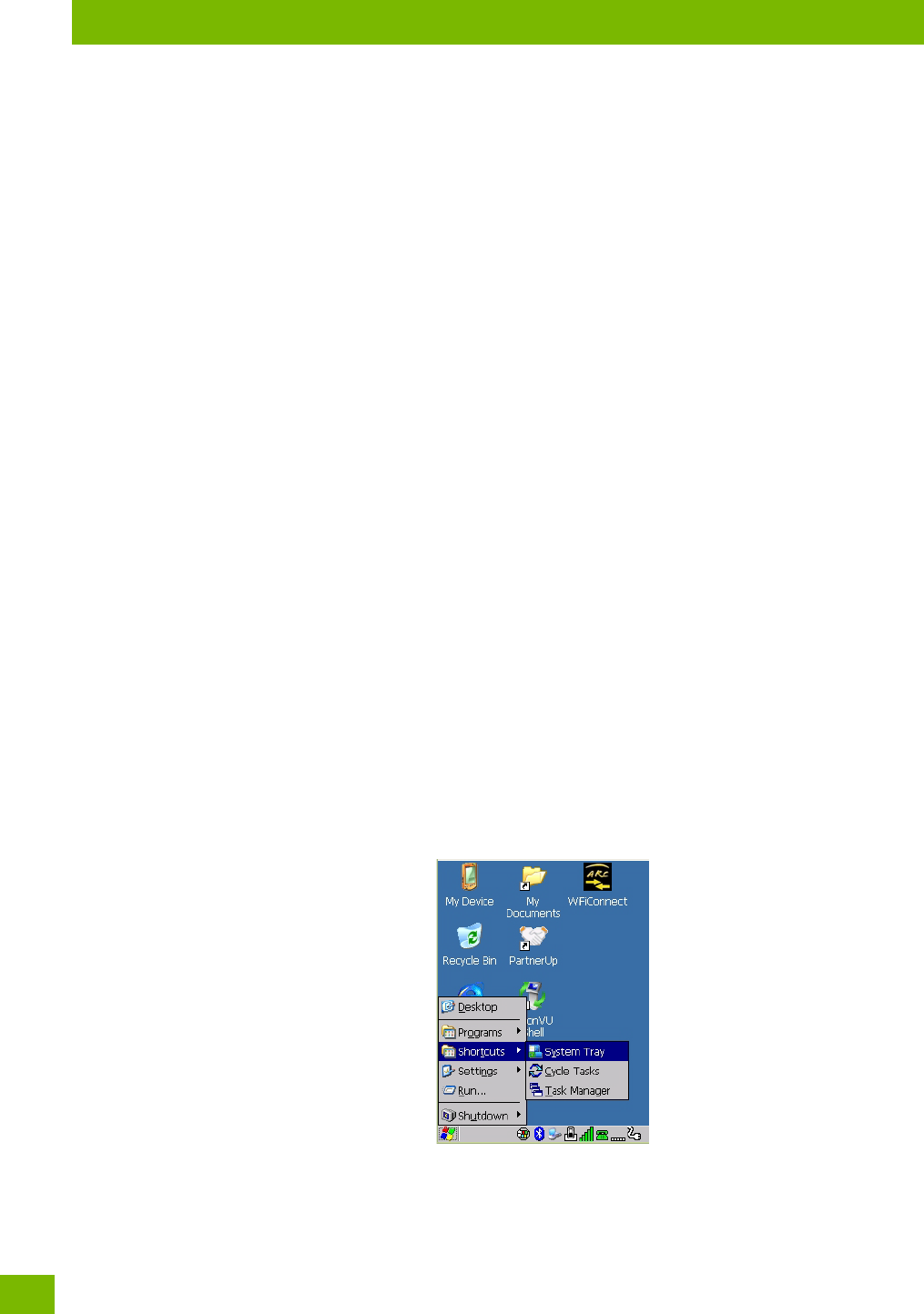
3.7.2.2.2 Shortcuts
Figure 3.6 Shortcuts Sub-Menu
System Tray
If your touchscreen is not enabled, you can use the System Tray option to access the icons in the taskbar at
the bottom of the screen. The taskbar displays indicators such as a radio signal icon. These indicators are
attached to dialog boxes that provide additional information.
Chapter 3: Getting To Know Your 8516
The Windows Classic Shell Startup Desktop
29
Psion 8516 Vehicle-Mount Computer User Manual
•Choose Shortcuts>System Tray.
When System Tray is chosen, the taskbar icons become accessible. To display the dialog box attached to an
icon:
• Use the arrow keys to highlight an icon, for example, the Bluetooth icon.
• Press [ENTER] to display the Bluetooth menus.
Cycle Tasks
When Cycle Tasks is selected (and the Task Manager is not open), you can cycle through active applications.
To cycle through your active applications:
•Choose Shortcuts>Cycle Tasks, or
• Press [ALT] [TAB].
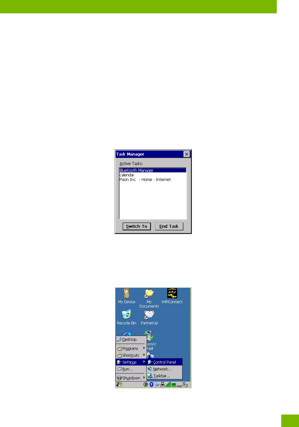
Task Ma n ag er
The Tas k M anag er allows you to switch to another task or to end an active task. To display the task manager
window:
•Tap on Shortcuts>Task Manager, or
• Press [ALT] [ESC].
3.7.2.2.3 Settings
The Settings sub-menu includes the following settings: Control Panel, Network and Dial-up Connections
and Taskbar and Start Menu.
Figure 3.7 Settings Sub-Menu
Chapter 3: Getting To Know Your 8516
The Windows Classic Shell Startup Desktop
Psion 8516 Vehicle-Mount Computer User Manual
30
Control Panel
The Control Panel contains applets used to configure hardware, the operating system and the shell. If your
8516 is running with the Psion Open TekTerm application or another application, additional configuration
applets may appear in the Control Panel.
Network and Dial-Up Connections
The Network and Dial-up Connections window allows you to configure the 8516 network interfaces or
execute an existing configuration. Refer to “Connectivity” on page 12 for radio setup details.
Taskbar and Start Menu
The Task bar a nd Start M e n u option displays a dialog box in which you can customize the taskbar, choosing
which options will be displayed. Refer to “Customizing the Taskbar” on page 26 for additional details about
this option.
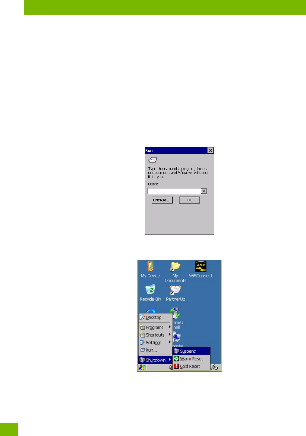
3.7.2.2.4 Run
Choosing the Run option from the Start Menu displays a dialog box in which you can enter the name of the
program, folder or document you want to open or launch.
3.7.2.2.5 Shutdown
The Shutdown menu includes these options: Suspend, Warm Reset and Cold Reset.
Suspend
The Suspend option suspends the 8516 immediately. This is equivalent to turning the Vehicle-Mount off.
Warm Reset
The Warm Reset option resets the Vehicle-Mount, leaving all saved files and registry settings intact. Any
unsaved data is lost.
Chapter 3: Getting To Know Your 8516
The PsionVU Desktop Shell
31
Psion 8516 Vehicle-Mount Computer User Manual
Cold Reset
The Cold Reset option resets the Vehicle-Mount (see page 11). Any files not stored in permanent memory
are lost; however, the registry settings are saved.
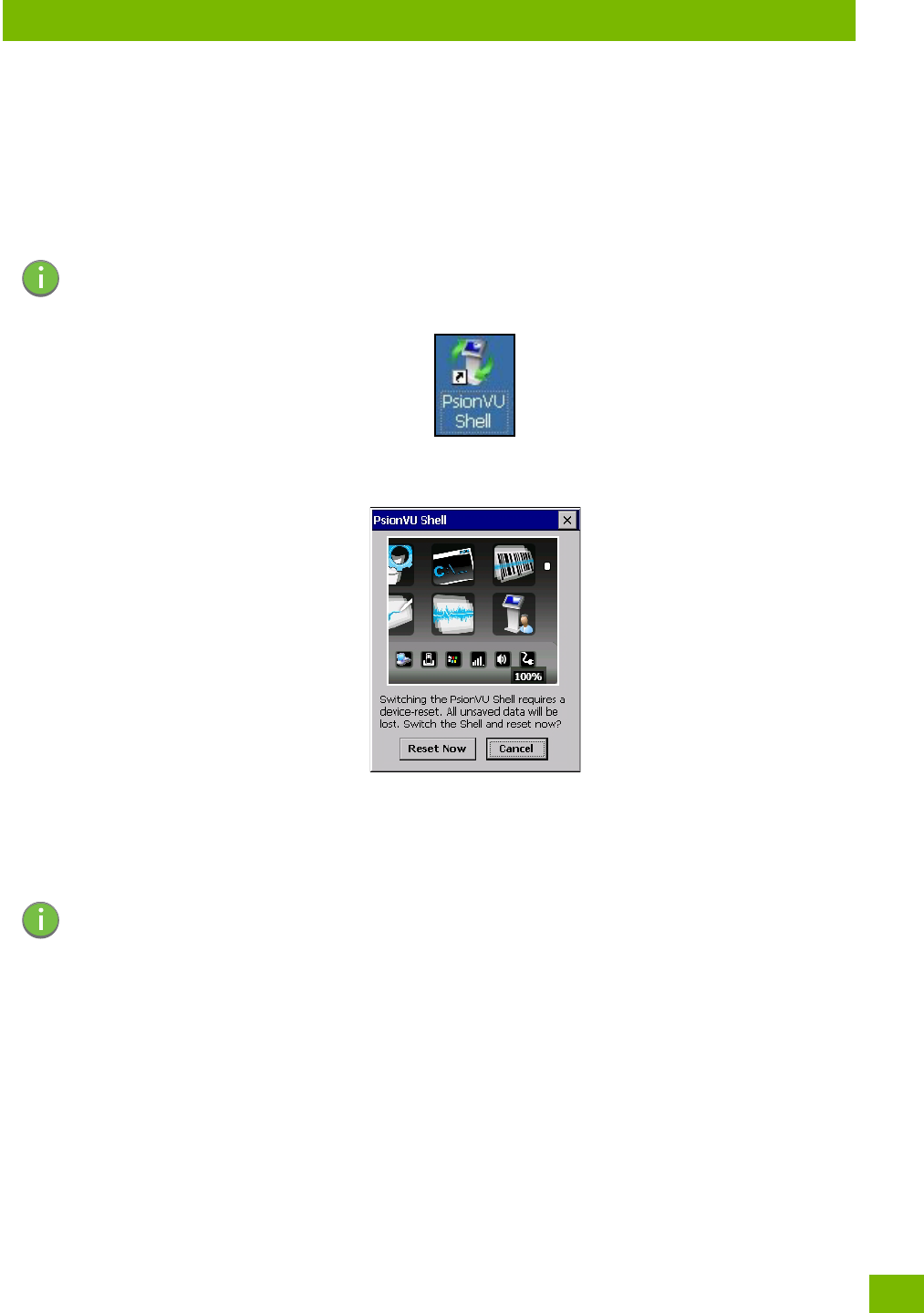
3.8 The PsionVU Desktop Shell
The appearance and actions of the desktop can be changed by tapping on the PsionVU Shell icon on your
desktop, which activates the PsionVU shell.
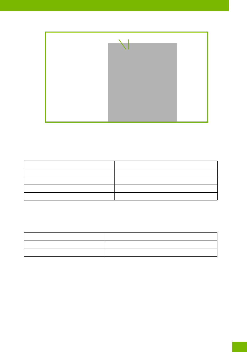
Figure 3.8 Switch to PsionVU Shell
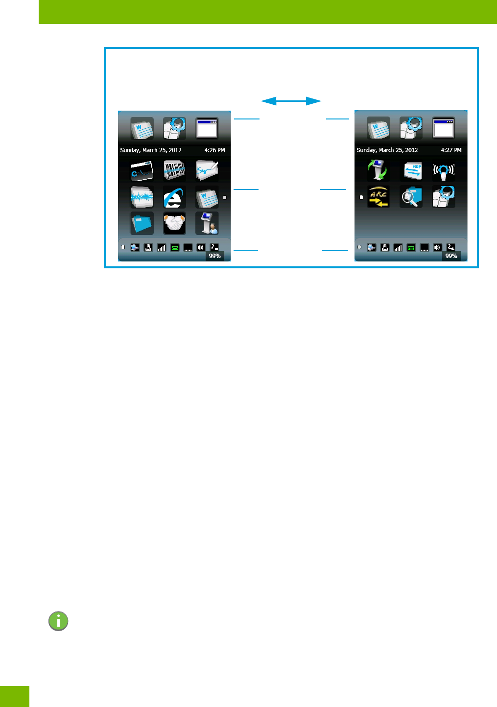
After resetting the 8516, the desktop appearance will be very different. The programs are accessed with
finger (or stylus) taps and swipes. If there are more applications than shown on one screen, a white ani-
mated dot will be present on the side of the screen in the direction of the next set of icons. Swiping the
screen to that direction will move the display to the next screen.
Note: The 8516 will be reset if you choose to switch shells.
Note: Although the Desktop appearance defaults to the “Ingenuity” theme, the theme is not
changed using the PsionVU Shell icon. To change themes, open the Shell Settings>Advanced
menu in PsionVU Access (see “Shell Settings” on page 81).
Chapter 3: Getting To Know Your 8516
The PsionVU Desktop Shell
Psion 8516 Vehicle-Mount Computer User Manual
32
A different program, PsionVU Access, enables you to customize your computer settings, remove or add
shortcuts to the Favourites Bar and Control Panel, and limit access to various different components on the
computer and the system tray icons for security. For details see “PsionVU Access” on page 79. To change
your Desktop background, refer to “Shell Settings” on page 81.
Active Tasks Bar
Open applications are shown in the top bar—the most recently opened is the first icon on the left. Tapping
once on a program icon will maximize the application. This feature replaces the Task Manager of the
Windows Classic Shell.
Date/Time Bar
Tapping once on the date or time will open the Date/Time Properties settings to enable you to change your
settings and time zone.
Favourites Bar
The Favourites Bar replaces the Windows Classic Shell’s Desktop and Start Menu. These icons are the
program shortcuts from your Windows\Start Menu. Tapping once will open the program. If you tap and hold
on an icon, the application name is displayed.
Notifications Bar
This bar shows the run-time program notifications for Battery, Volume, Wi-Fi, Phone or GPRS, and other no-
tifications for the programs you are running. This feature replaces the Taskbar of the Windows Classic
Shell.
Desktop Minimized View
When an application is opened and maximized, the desktop view is minimized and the Notifications Bar is
shown at the bottom of the screen. Tapping anywhere on the Notifications Bar (except on the SIP) will
restore the PsionVU desktop.
Hold the stylus or your finger on the Active Tasks, Favourites, or Notifications Bar,
Favourites Bar
Notifications Bar
Active Tasks Bar
and swipe to the left or right to switch to the next screen.
Note: In order to use the SIP, turn on the automatic settings in Control Panel>Input Panel.
Chapter 3: Getting To Know Your 8516
Restoring the Windows Classic Shell
33
Psion 8516 Vehicle-Mount Computer User Manual
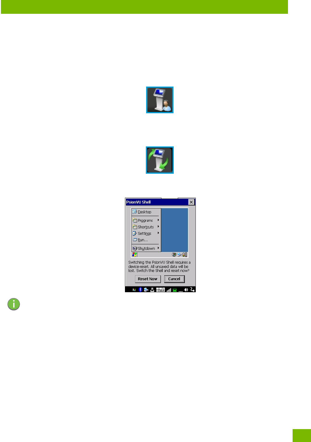
PsionVU Access
The PsionVU Access program allows you to open a different program, PsionVU, which enables you to cus-
tomize your computer settings, remove or add shortcuts to the Favourites Bar and Control Panel, and limit
access to various different components on the computer and the system tray icons for security. For details
see “PsionVU Access” on page 79. To change your Desktop background, refer to “Shell Settings” on
page 81.
To open PsionVU:
•Tap on the PsionVU Access icon in the Favourites Bar.
3.8.1 Restoring the Windows Classic Shell
The default Desktop appearance and actions can be restored by tapping on the PsionVU Shell icon in the
Favourites Bar.
Figure 3.9 Shell Switch to Windows Classic Shell Desktop
3.9 General Maintenance
3.9.1 Caring for the Touchscreen
The touchscreen is covered with a thin, flexible polyester plastic sheet with a conductive coating on the
inside. The polyester can be permanently damaged by harsh chemicals and is susceptible to abrasions and
scratches. Using sharp objects on the touchscreen can scratch or cut the plastic, or crack the internal con-
ductive coating. The chemicals listed below must not come into contact with the touchscreen:
•mustard
• ketchup
• sodium hydroxide
•concentrated caustic solutions
• benzyl alcohol
•concentrated acids
Note: The 8516 will be reset if you choose to switch shells.

Chapter 3: Getting To Know Your 8516
Cleaning the 8516
Psion 8516 Vehicle-Mount Computer User Manual
34
If the touchscreen is used in harsh environments, consider applying a disposable screen protector
(RV6105). These covers reduce the clarity of the display slightly but will dramatically extend the useful life
of the touchscreen. When they become scratched and abraded, they are easily removed and replaced.
Do not to expose the touchscreen to direct sunlight for prolonged periods of time. If this is unavoidable, use
a UV screen protector to extend the life of the screen.
3.9.2 Cleaning the 8516
• Use only mild detergent or soapy water to clean the Vehicle-Mount unit.
• Avoid abrasive cleaners, solvents or strong chemicals for cleaning. The 8516 has a plastic case that is
susceptible to harsh chemicals. The plastic is partially soluble in oils, mineral spirits and gasoline. The
plastic slowly decomposes in strong alkaline solutions.
• Exposure to aircraft de-icing fluids can degrade the plastics on 8516. If the 8516 is used near aircraft
de-icing environments, regular rinsing with water is recommended.
• To clean ink marks from the keypad and touchscreen, use isopropyl alcohol.
Important: Do not immerse the unit in water. Dampen a soft cloth with mild detergent to wipe
the unit clean.
To prevent damage to the touchscreen, use only your finger or the stylus (pen)
supplied with your 8516.

35
Psion 8516 Vehicle-Mount Computer User Manual
4CONFIGURATION
CONFIGU RATION 4
4.1 Overview of Software.....................................................39
4.1.1 Psion Software Advantage.............................................39
4.1.2 Microsoft Software.................................................39
4.2 The Control Panel........................................................39
4.2.1 Control Panel Applications.............................................40
4.3 App Launch Keys........................................................42
4.4 Bluetooth® Setup .......................................................44
4.4.1 Paired.........................................................44
4.4.2 Device.........................................................46
4.4.2.1 Discovering and Removing Devices..................................46
4.4.2.2 Filtering By Class of Device (COD)...................................46
4.4.2.3 Device Pop-up Menu ..........................................47
4.4.2.4 Pairing a Device.............................................47
4.4.3 Servers........................................................49
4.4.4 Mode.........................................................49
4.4.5 About.........................................................50
4.4.6 The Bluetooth GPRS WAN Connection......................................50
4.5 Certificates ...........................................................53
4.6 Data Transfer between 8516 and a PC............................................54
4.6.1 Using Microsoft ActiveSync............................................54
4.6.2 Using Windows Mobile Device Center......................................54
4.7 Display Properties.......................................................55
4.7.1 Background .....................................................55
4.7.2 Appearance .....................................................55
4.7.3 Backlight.......................................................55
4.8 Dr. Debug.............................................................57
4.8.1 Status.........................................................57
4.8.2 Utilities . . ......................................................57
4.8.3 Motion Meter.....................................................58
4.8.4 Settings........................................................58
4.9 Error Reporting.........................................................58
4.10 GPS (Global Positioning System) Settings..........................................59
4.10.1 Power.........................................................59
4.10.2 Profiles........................................................60
4.10.3 Programs.......................................................60
4.10.4 AGPS......................................................... 61
4.10.5 Info ..........................................................62
4.11 Input Panel ...........................................................62
4.11.1 Keyboard Properties................................................63
4.11.1.1 Key Repeat................................................63
4.11.1.2 Keyboard Backlight...........................................64
4.11.1.3 Keyboard One Shot Modes.......................................65
4.11.1.4 Keyboard Macro Keys..........................................65
4.11.1.5 Unicode Mapping............................................67
4.11.1.6 Scancode Remapping..........................................68

Psion 8516 Vehicle-Mount Computer User Manual
36
4.11.1.7 Lock Sequence..............................................70
4.12 Manage Triggers........................................................ 71
4.12.1 Trigger Mappings.................................................. 71
4.12.2 Add and Edit Trigger Mapping...........................................72
4.13 Microphone...........................................................73
4.14 Open TekTerm..........................................................74
4.15 PartnerUp............................................................74
4.16 Pocket PC Compatibility ....................................................75
4.17 Power Properties........................................................75
4.17.1 Battery Capacity...................................................75
4.17.2 Power Saving Suspend...............................................76
4.17.3 Suspend Threshold and Estimated Battery Backup..............................76
4.17.4 Advanced.......................................................77
4.17.5 Built-in Devices ...................................................77
4.17.6 Battery Health....................................................78
4.18 PsionVU Access.........................................................79
4.18.1 Administrator Password..............................................80
4.18.2 Shell Settings .................................................... 81
4.18.3 Restrictions .....................................................83
4.18.4Control Panel Settings...............................................83
4.18.5 Import/Expo to File.................................................84
4.19 Remote Desktop Connection.................................................85
4.20 Scanners.............................................................86
4.20.1 Barcodes.......................................................86
4.20.1.1 Scanner..................................................86
4.20.1.2 Restoring Default Settings.......................................86
4.20.2Options........................................................87
4.20.2.1 Double Click Parameters........................................88
4.20.2.2Display Parameters...........................................88
4.20.2.3Data Handling..............................................89
4.20.3Translations.....................................................89
4.20.3.1 Case Rules................................................90
4.20.4Ports .........................................................90
4.20.4.1 Port Replicator Port A (COM5) and Port B (COM6).........................91
4.21 Storage Manager........................................................92
4.21.1 Formatting a Memory Card............................................92
4.21.2 Creating Partitions.................................................92
4.21.3 Partition Management...............................................93
4.22 Stylus Properties........................................................95
4.22.1 Double-Tap......................................................95
4.22.2Calibration......................................................95
4.22.3Touch.........................................................95
4.23 System Properties.......................................................96
4.24 Total Recall ...........................................................97
4.24.1 Creating a Backup..................................................97
4.24.2Creating a Clone...................................................98
4.24.3Managing Profiles..................................................99
4.24.3.1 Viewing a Profile.............................................99
4.24.3.2 Profile Options..............................................99
4.24.4Deleting a Profile................................................. 100

37
Psion 8516 Vehicle-Mount Computer User Manual
4.25 TweakIt..............................................................101
4.25.1 Advanced.......................................................101
4.25.1.1 Advanced CE Services Settings....................................101
4.25.1.2 Advanced Interface and Network Settings..............................102
4.25.1.3 Advanced Services Settings......................................102
4.25.2Registry Editor....................................................103
4.26 Voice – Using the WWAN Phone Dialer ...........................................103
4.26.1 Dialing a Number..................................................104
4.26.2Receiving an Incoming Call ............................................104
4.26.3Voice Menu......................................................104
4.26.4File Menu – Phonebook Management ......................................106
4.27 Volume & Sounds Properties.................................................108
4.27.1 Volume Adjustments................................................108
4.27.2Sound Adjustments.................................................108
4.28 Wi-Fi Config...........................................................109
4.28.1 Wi-Fi Config: Status.................................................109
4.28.2Wi-Fi Config: Configure...............................................109
4.28.2.1 Manually Creating a Network .....................................110
4.28.2.2Authentication Mode..........................................110
4.28.2.3Encryption................................................ 111
4.28.2.4EAP....................................................112
4.28.2.5Verify Server Certificate........................................112
4.28.2.6Enable OPMK...............................................112
4.28.2.7 Connecting the Wireless Network...................................113
4.28.3Configuring TCP/IP.................................................113
4.28.3.1 IP Address ................................................113
4.28.3.2 Name Server...............................................115
4.28.4Wi-Fi Config: Advanced...............................................115
4.28.5Monitoring the Network Connection.......................................116
4.29 WiFi Connect A.R.C........................................................116

Chapter 4: Configuration
Overview of Software
39
Psion 8516 Vehicle-Mount Computer User Manual
4.1 Overview of Software
The 8516 programs and applications are accessed through two main areas from the Desktop: Programs and
Settings>Control Panel. This chapter details the configuration for the major software from both areas, listed
alphabetically.
4.1.1 Psion Software Advantage
Psion Software Advantage is a collection of applications and features designed to support system adminis-
trators and end users. These tools enable enterprises to customize the product to meet their needs and to
maximize productivity.
AGPS PsionVu
App Launch Keys TweakIt
Battery Health Scanner
Bluetooth Manager Total Recall
Dr. Debug Manage Triggers
PartnerUp WiFi Config
WiFiConnect A.R.C.
4.1.2 Microsoft Software
Windows CE 6.0 R3 is a 32-bit, real-time, multitasking Operating System. The OS features a small footprint,
with compatibility to port existing Win32 applications and Touch & Gesture support.
Some of the major WCE 6.0 R3 components are:
Control Panel, where both Psion Advantage and Microsoft applications are grouped
Flash Lite
Internet Explorer Embedded
Microsoft WordPad
Remote Desktop Connection
Windows Explorer
4.2 The Control Panel
The Windows Embedded CE Control Panel provides a group of applications through which you can set a
variety of system-wide properties, such as power, keyboard sensitivity, network configuration, system
backup, desktop appearance, and so on.
When the 8516 boots up, the startup desktop (Windows Classic Shell) is displayed, and any applications
stored in the Startup folder start up immediately.
To access the Control Panel:
• Press [Windows] to display the Start Menu.
•Tap on Settings>Control Panel.
If you’re using the keyboard:
• Press [Windows] to display the Start Menu.
• Highlight Settings in Start Menu, and press the [RIGHT] arrow key to highlight the Control Panel.
• Press the [ENTER] key.
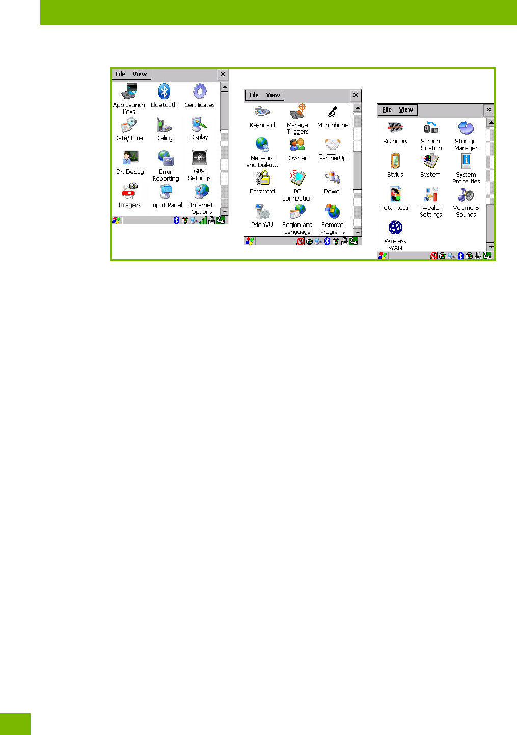
The Control Panel folder contains icons used in the setup of your 8516.
Chapter 4: Configuration
Control Panel Applications
Psion 8516 Vehicle-Mount Computer User Manual
40
Figure 4.1 Control Panel Icons
4.2.1 Control Panel Applications
The Control Panel provides a group of applications that allow you to customize and adjust settings on your
8516. This section shows the related icons in the Control Panel and gives a brief description of each.
App Launch Keys
By mapping keys to applications using this program, you can then launch those applications from a single
key-press.
Bluetooth
Opens the Bluetooth Manager which provides options for configuring various Bluetooth peripherals. It also
provides the capability to use a Bluetooth-enabled cellular phone as a data modem to exchange informa-
tion with other Bluetooth devices and provide network access.
Certificates
This program provides access to the Certificates Manager and Stores. The Certificates Manager displays
the Certificates in the Windows Certificates Store, and allows you to import, delete, and view these certifi-
cates. “Certificates” on page 53 directs you to the appropriate setup information.
Date/Time
Allows you to set the current Month, Date, Time, and Time Zone on your unit.
Dialing
Specifies dialing settings, including area code, country code, dial type and the code to disable call waiting.
You can store multiple patterns—for example, ‘Work’, ‘Home’, and so on using this dialog box.
Display
Changes the display backlight and the appearance (colour scheme) on the unit desktop.
Dr. Debug
Provides both error diagnostic and troubleshooting tools.
Error Reporting
Allows you to enable or disable Microsoft error reporting prompts.
GPS Settings
Allows you to enable and configure GPS operation.

Chapter 4: Configuration
Control Panel Applications
41
Psion 8516 Vehicle-Mount Computer User Manual
Input Panel
Provides the framework for a Microsoft Soft Input Panel (SIP) should you need to design your own SIP, or
change some soft keyboard options.
Internet Options
Provides options to configure your Internet browser. You can determine items such as the default and
search page that the browser applies when connecting to the Internet, the cache size, the Internet connec-
tion options, and the security level that is applied when browsing.
Keyboard
Toggles character repeat on and off and specifies delay and rate for repeated characters. It also allows you
to adjust the keyboard backlight threshold and intensity, and many other functions.
Manage Triggers
This utility allows you to define buttons as triggers for different devices. For example you would use this
utility to configure a button for the scanner, or RFID reader.
Microphone
Enables you to adjust the gain for the specific microphones associated with your Vehicle-Mount.
Network and Dial-up Connections
Displays network interfaces and allows new dial-up and VPN interfaces to be created. It also allows Windows
configuration of the interface. Refer to “Connectivity” on page 12 for details.
Owner
Provides fields in which you can specify owner information. A Notes tab allows additional information to be
entered and displayed when the unit is powered up. Network ID tab information is used to access network
resources. (This information should be provided by your System Administrator.)
PartnerUp
This app displays a number of pre-loaded applications. By tapping on an application in the list, you are
taken to the associated web site and allowed to install the application.
Password
Allows you to assign a password to restrict access to elements of the unit. Once assigned, password access
cannot be circumvented so it is important that you write down your password and keep it in a safe place.
PC Connection
Enables direct connection to a desktop computer (or through ActiveSync—see “Data Transfer between 8516
and a PC” on page 54). Selecting the Change Connection button allows you to change the type of direct
connection to your PC.
Power
Displays battery pack power status. (Alternately, battery status can be accessed through the taskbar.) Addi-
tional tabs allow you to determine suspend states and specify a suspend threshold.
PsionVU
PsionVU enables you to customize your computer settings, remove or add shortcuts to the desktop and
Control Panel, and lock down access to various different components on the computer and the system tray
icons for security. With PsionVU and PsionVU Shell (see “The PsionVU Desktop Shell” on page 31) you can
customize the entire look and feel of your User Experience.
Region and Language
Allows you to specify the local language that is to be displayed on the Vehicle-Mount screen along with the
format of numbers, currency, time and date for your region.

Chapter 4: Configuration
App Launch Keys
Psion 8516 Vehicle-Mount Computer User Manual
42
Remove Programs
Lists the programs that can be removed from your unit. To remove a program, select it and then click on
the Remove button.
Scanners
Provides scanner parameters and the barcode symbologies that the 8516 barcode scanner will successfully
read.
Storage Manager
Allows you to view information about the storage devices that are present, such as SD-MMC flash cards. For
details, see page 92.
Stylus
Adjusts how Windows Embedded CE recognizes your double-tap (as slow or rapid successive taps). In the
Calibration tab, you can recalibrate your touchscreen by tapping on the Recalibrate button and following
the directions on the screen.
System
You can display the system and memory properties, as well as create your device name. In the Memory tab,
you can allocate memory between storage memory and program memory.
System Properties
Identifies the computer’s software and hardware components, indicating which components are installed,
their version or pa numbers, and whether they are enabled or disabled.
Total Rec al l
Provides access to a backup\restore and deployment utility to maintain applications and settings over cold
reboots and for multiple devices.
TweakIt
Allows you to change Advanced System Settings (interface, network, and servers), User System Settings
(display font size), and provides the Registry Editor.
Volume & Sounds
Allows you to adjust the volume of the sound emitted to indicate events like warnings, key clicks, and screen
taps. You can also configure system (Windows) sounds and .wav files.
Wireless WAN
Provides access to technology like GSM/GPRS, which allows wide area networking capability such as inter-
net browsing via GSM/GPRS. It also provides access to the Phone API. For detailed information, see
Appendix E: “Wireless Wide Area Network (WWAN) Settings”.
4.3 App Launch Keys
The App Launch Keys icon allows you to map a key to an application so that you can then launch the appli-
cation from a single key-press.
•In the Control Panel, choose the App Launch Keys icon.
To assign an application key:
• Tap the Add button.
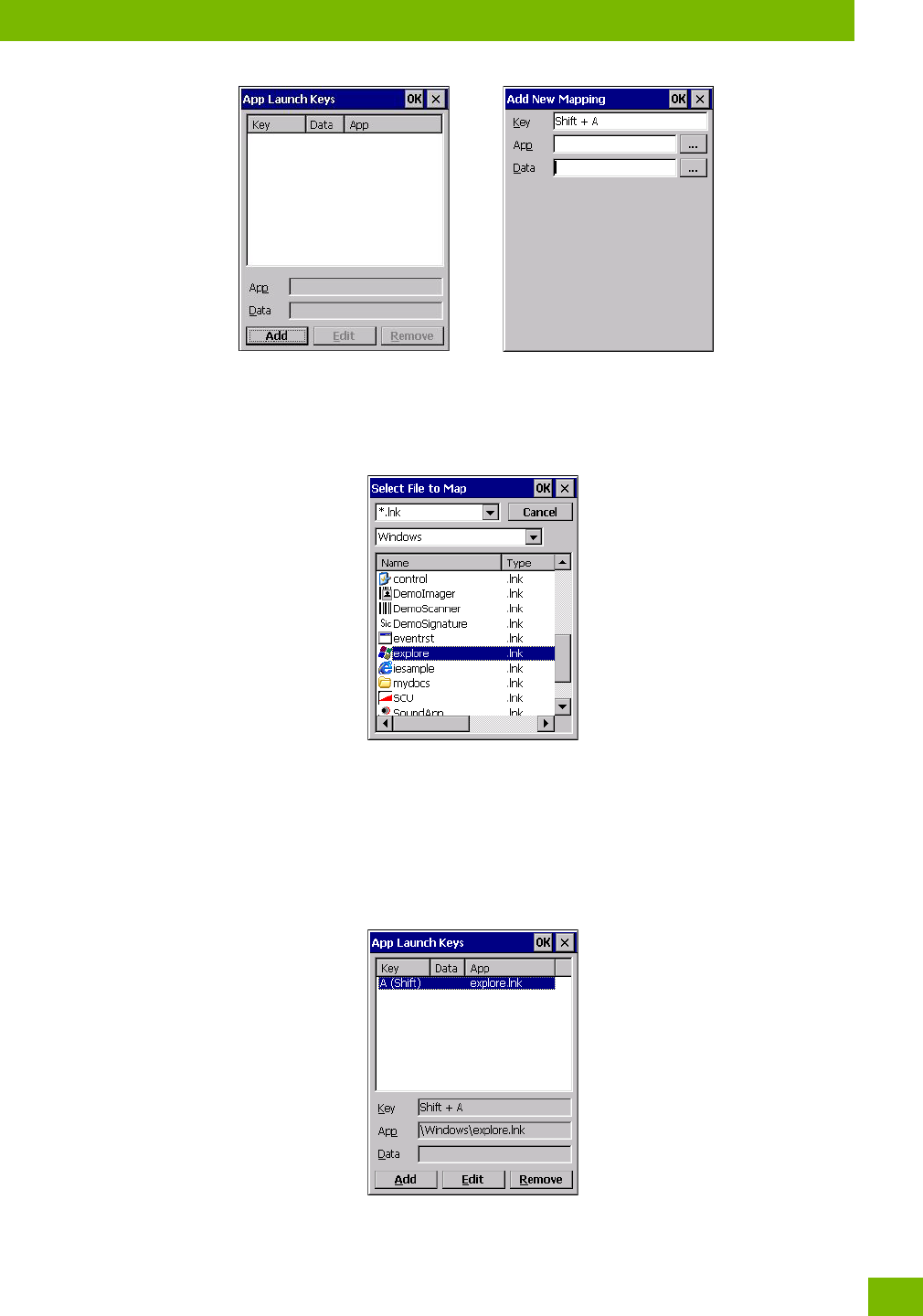
Chapter 4: Configuration
App Launch Keys
43
Psion 8516 Vehicle-Mount Computer User Manual
• Press the key you want to use to launch an application. (If an unsupported key is pressed, a message
appears on this screen letting you know.)
The cursor moves to the App field and a new screen is displayed where you can choose the application to
which you want to assign the application key. If you need to, you can Browse through the information in
your 8516 until you locate the application you want to launch.
• Once you’ve selected the file you want to map, tap on OK.
The cursor moves to the Data field. You can use this field if you need to need to define command line pa-
rameters for your application. If you don’t want to assign any parameters, you can leave the Data field
blank. If, for example, you want to assign an application launch key to launch the WordPad application, you
can leave this field blank. If you want to assign an application launch key that will open a specific document
in the WordPad application, you need to browse to and choose that document while the cursor is in the Data
field.
•Tap on OK.
• If you need to Edit, Remove or Add another App Launch Key, you can do it from this final screen. Oth-
erwise, tap on OK to save your Application Launch Key.
Chapter 4: Configuration
Bluetooth® Setup
Psion 8516 Vehicle-Mount Computer User Manual
44
• To launch the application you chose, press the application key you assigned.
4.4 Bluetooth® Setup
Bluetooth is a global standard for wireless connectivity for digital devices and is intended for Personal Area
Networks (PAN). The technology is based on a short-range radio link that operates in the ISM band at
2.4 GHz. When two Bluetooth-equipped devices come within a 10 metre (32 ft.) range of each other, they
can establish a connection. Because Bluetooth utilizes a radio-based link, it does not require a line-of-sight
connection in order to communicate.
It is possible to communicate with a variety of Bluetooth peripherals, including GSM/GPRS handsets, scan-
ners, printers, and so on.
Psion provides built-in support for:
• GSM/GPRS universal handset
•Bluetooth printer
•Bluetooth headset
Keep in mind that Bluetooth and IEEE 802.11g radios both operate in the 2.4GHz band. Although the 8516
includes features to minimize interference, performance of the system will not be optimal if you use both
radios simultaneously. Typically, when both radios operate in the Vehicle-Mount at the same time, they
cannot transmit simultaneously—this has a negative impact on overall system throughput. To minimize the
impact on the backbone 802.11 network, Psion recommends using Bluetooth peripherals that have low
transaction rates (such as printers and scanners).
Bluetooth peripherals are configured by choosing the Bluetooth icon in the Control Panel. In addition,
review the manual shipped with your Bluetooth device to determine the method used to associate with the
8516 host.
•In the Control Panel, choose the Bluetooth icon to display the Bluetooth Manager screen.
The Bluetooth Manager allows users to search, pair and connect to other Bluetooth devices within their
personal area network.
The Bluetooth radio is disabled by default. Before you begin the setup process:
• Tap on the Mode tab, and tap in the checkbox next to Turn on Bluetooth. Tap on OK.
When the radio is enabled, a Bluetooth icon appears the taskbar at the bottom of the screen. It is ready
for setup.
4.4.1 Paired
This tab lists all paired devices and their corresponding services. The format of the name is <Device
Name>:<Service Name>. Additional information may appear in this screen such as the Port Numbers for
Serial Profiles service.
Note: The Bluetooth radio uses an internal antenna.
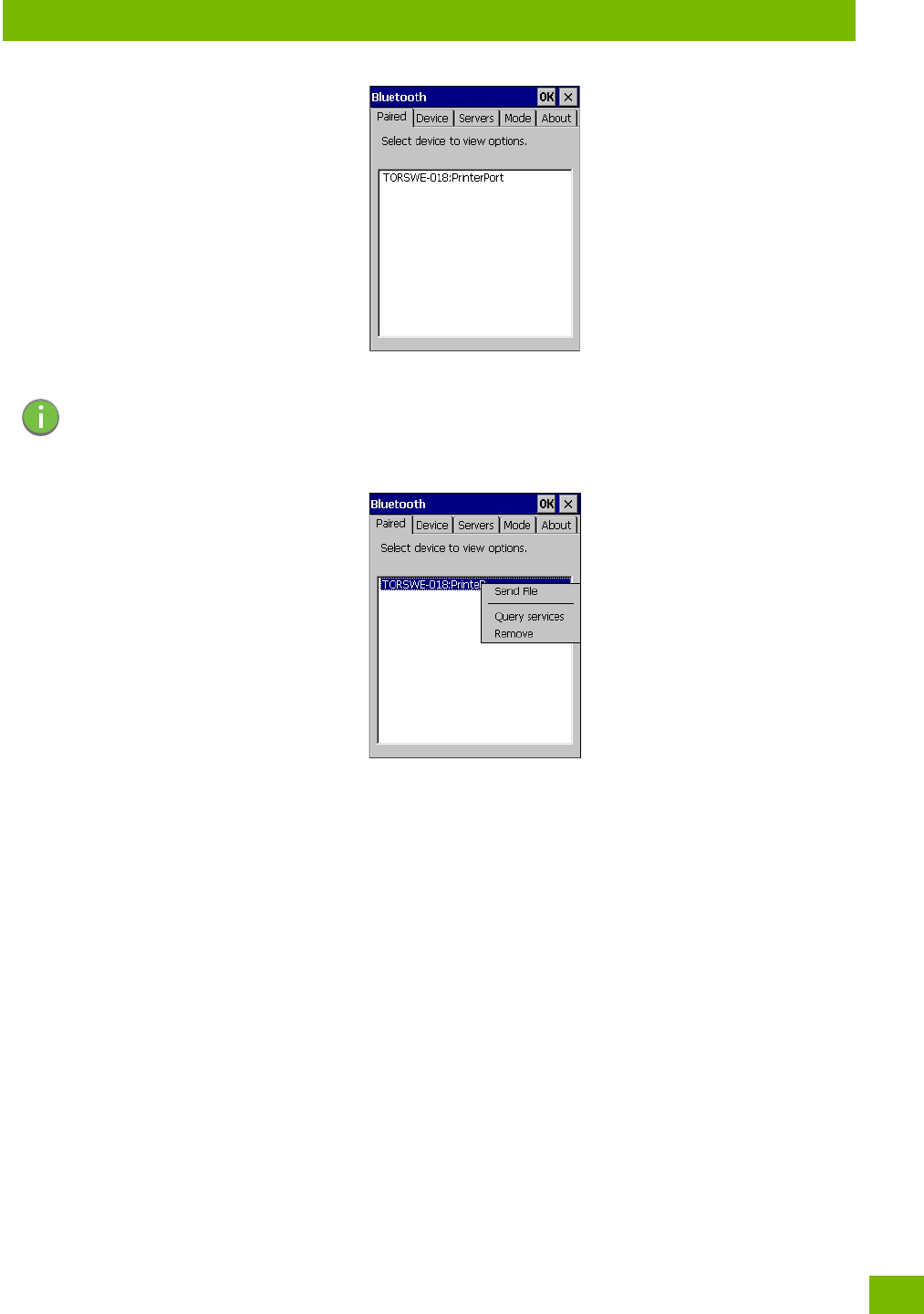
Chapter 4: Configuration
Paired
45
Psion 8516 Vehicle-Mount Computer User Manual
To learn how to scan for devices to pair, review “Device” on page 46.
• Tap on an item in the Paired tab to display an associated pop-up menu.
The displayed menu depends on the type of the service chosen.
Query Services and Remove Commands
•Query Services displays a Services dialog box where a pairing service is chosen.
•Remove unpairs the highlighted service and deletes the entry from the tab.
OBEX OPP (Object Exchange-Object Push Profile) Commands
The OPP defines two roles—a Push Server and a Push Client. Push Server is the device that provides an
object exchange server. Push Client is the device that pushes and pulls objects to and from the Push Server.
OBEX OPP contains the following unique menu option:
•Send File displays an Open File dialog box where the file to be sent can be selected. When the transmis-
sion begins, another dialog box tracks the progress of the file transmission.
HSP/HFP (Headset Profile/Hands-Free Profile) Service Commands
The HSP (Headset Profile) allows users to connect their device to Bluetooth enabled headsets and other
audio devices.
HSP/HFP services provide the following unique menu options:
•Connect Audio establishes an audio connection to the Bluetooth headset.
•Disconnect Audio disconnects the audio connection from the Bluetooth headset.
•Volume Control displays a dialog box where the headset and microphone volume can be adjusted.
Note: If a service is actively paired and connected, the device and its services are displayed in bold
typeface in this list.
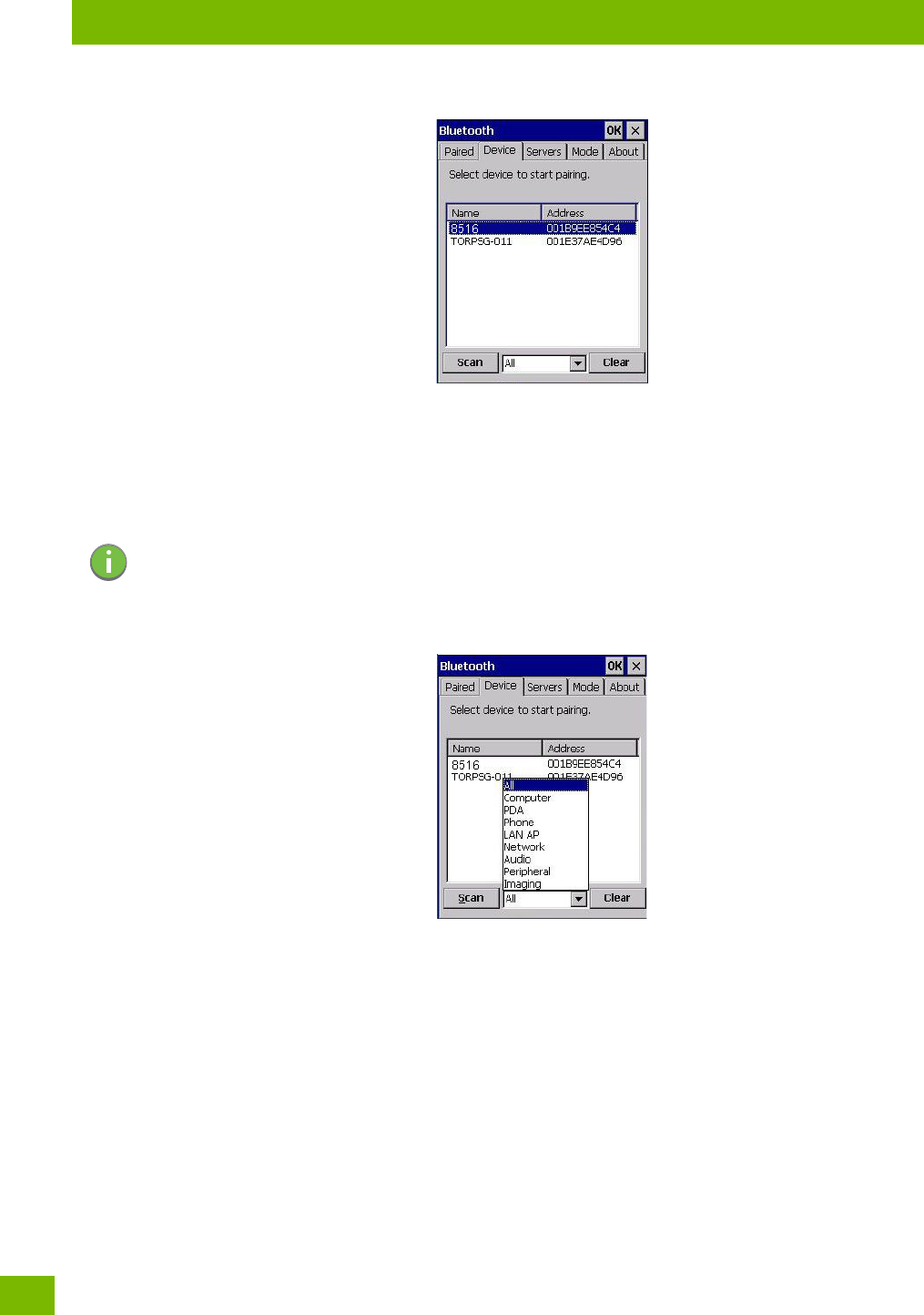
Chapter 4: Configuration
Device
Psion 8516 Vehicle-Mount Computer User Manual
46
4.4.2 Device
In this tab, users can discover and display Bluetooth devices.
4.4.2.1 Discovering and Removing Devices
Scan discovers Bluetooth devices in range of the 8516 and lists them in this tab. Any existing devices previ-
ously discovered and listed will also be displayed.
Clear removes all Bluetooth devices listed except those with currently paired and connected services.
4.4.2.2 Filtering By Class of Device (COD)
This menu allows you to filter the displayed devices by their COD. If, for example, you choose Computer
from this menu, only the devices that have the matching Computer COD value will be displayed. Choosing
All lists all detected devices.
Note: To limit the number of devices listed to a particular type of device, refer to “Filtering By Class
of Device (COD)”, next section.
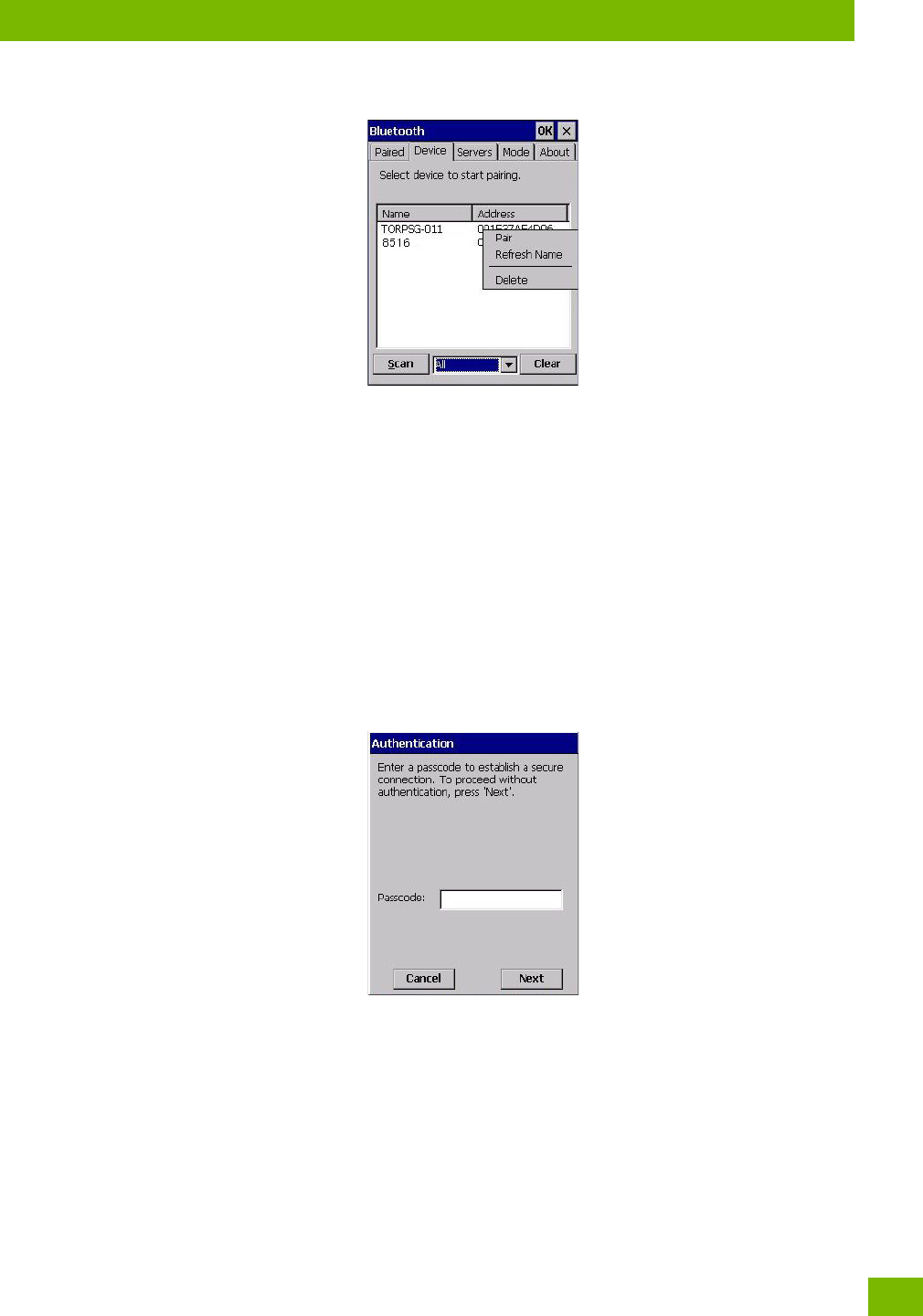
Chapter 4: Configuration
Device
47
Psion 8516 Vehicle-Mount Computer User Manual
4.4.2.3 Device Pop-up Menu
The Device pop-up menu allows you to pair a device, update a device name or delete a device from the list.
Pair begins the pairing process by inquiring the services and profiles of the discovered device. An authenti-
cation dialog box is displayed the first time a Bluetooth device is paired.
Refresh Name repeats the device name inquiry, updating the name. This command is useful if a device is
listed without a name (unknown), or if a device name has been changed remotely.
Delete removes this device from the list.
4.4.2.4 Pairing a Device
To pair devices:
• Follow the manufacturer’s instructions to place the remote device in pairing mode.
• Choose the Devices tab and Scan for devices in your area.
• When the scan is complete, tap on the device to which you want to pair.
• In the pop-up Device menu, tap on Pair.
An Authentication dialog box is displayed.
• If the remote device has authentication enabled, type the PIN in this dialog box.
• To proceed without authentication, tap on Next.
After entering the device PIN, the Services dialog appears with a list of services available for that device.

Chapter 4: Configuration
Device
Psion 8516 Vehicle-Mount Computer User Manual
48
• Click in the checkbox to the left of the service to activate it.
• Click on Done.
Services that require more information present a configuration dialog box. Serial Profile is an example.
This dialog box offers a number of additional options such as enabling Encryption and selecting four differ-
ent Modes: Serial, ActiveSync, Scanner, and Printer Port.
Serial is used for simple serial port communication.
ActiveSync is for ActiveSync-over-Bluetooth.
Scanner is used to create a connection to a barcode scanner. A serial connection is created, then the
Scanner Services is notified of the connection so that the incoming barcode scan will be forwarded to
Scanner Services directly.
Printer Port must be chosen here if you want to communicate with a paired Bluetooth printer. For further
details, see “Mode” on page 49.
• Once you’ve completed the information, tap on Next and then in the Services screen, click on Done.
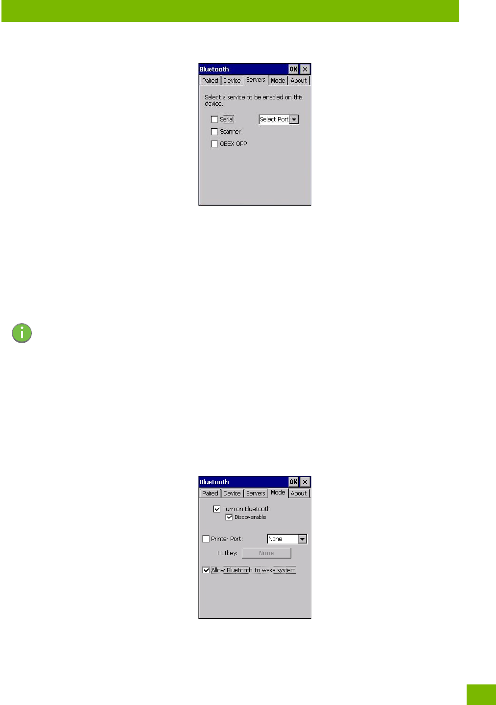
Chapter 4: Configuration
Servers
49
Psion 8516 Vehicle-Mount Computer User Manual
4.4.3 Servers
When a remote Bluetooth device initiates a Bluetooth connection to the 8516, the remote device is consid-
ered the ‘Bluetooth master’ and the Vehicle-Mount, the ‘Bluetooth slave’. In order for the remote device to
connect to the Vehicle-Mount, the 8516 must offer a service in the form of a server. The Servers tab allows
these services to be enabled and configured. There are three server services available: Serial, Scanner and
OBEX OPP.
Serial server enables the Serial Port Profile server; a Serial Port can be selected from the drop-down menu.
You can assign either a BSP or a COM prefix from the drop-down menu. BSP (Bluetooth Serial Port) was
created by Microsoft to allow Bluetooth to have its own serial prefix in order to free up virtual COM prefixes
as these are limited and are widely used.
Scanner server enables a Serial Port Profile server and then relays it to the Scanner Service (SCS). This is
used for Bluetooth barcode scanners that operate in client mode. SCS opens the server port and handles
the scanner input.
OBEX OPP server enables the Object Push Profile server. A warm reset must be performed on the 8516
after a change is made to this option. The OPP Server allows other Bluetooth devices to send files to this
device.
• Tap on the checkbox to activate the server.
4.4.4 Mode
Turn on Bluetooth activates the Bluetooth radio.
Discoverable determines whether the 8516 is visible or invisible to other devices.
Note: Even after a Serial Port Profile server is created, an application must open the created port
before a remote device can connect.
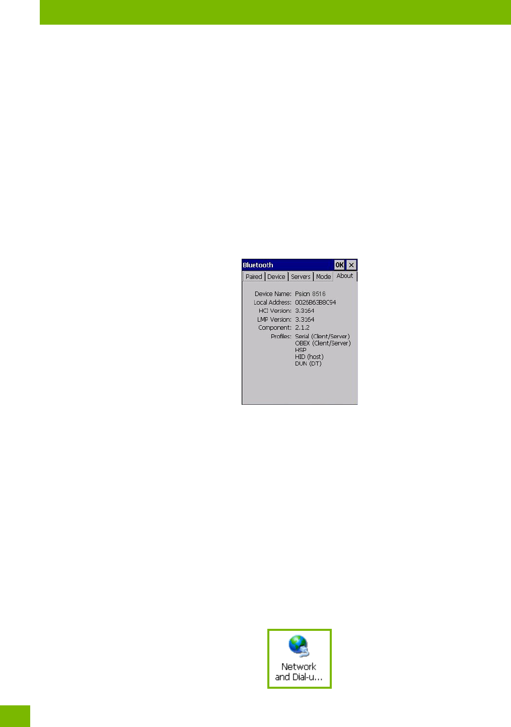
Chapter 4: Configuration
About
Psion 8516 Vehicle-Mount Computer User Manual
50
Printer Port allows you to assign and enable a virtual outgoing COM port selected from the drop-down
menu to communicate with a paired Bluetooth printer. Keep in mind that when a port is chosen, the printer
must be on and connected to the chosen port for a remote device to be able to connect.
• Select a port within the Printer Port drop-down list, e.g. BSP1:
• Check the Printer Port check box.
•Open the Device tab and tap on Scan.
• Tap-and-hold each Bluetooth Printer device entry and then select Pair, key-in the Passcode (if needed)
and then tap Done. DO NOT select any services!
•Close the Bluetooth Manager.
• Select the Bluetooth device to print to—you will need to key-in (or programmatically raise) the following
key sequence [CTRL] [ALT] [F1].
• You can now select the Bluetooth device to which you wish to print.
Allow Bluetooth to wake system allows remote Bluetooth devices to wake the 8516 by requesting a Blue-
tooth service that requires host intervention. This feature can also be used when the 8516 is waking from
suspend to significantly to reduce the initialization time of the Bluetooth system.
4.4.5 About
Device Name displays the broadcasted name of the Vehicle-Mount. The name can be changed in the
System Properties applet: Start>Settings>Control Panel>System icon>Device Name tab.
Local Address displays the MAC address (BD_Addr) of the Bluetooth chip.
HCI Version & LMP Version display the version of the chip firmware.
Component indicates the version of the Psion Bluetooth Subsystem (the manager, drivers, etc).
Profiles lists the supported profiles on this specific 8516.
4.4.6 The Bluetooth GPRS WAN Connection
The following steps describe how to set up an Internet data connection using a GSM cellular telephone with
Bluetooth. The 8516 communicates via Bluetooth to the cell phone, which then accesses a WAN (Wide Area
Network) and transfers data using GPRS.
1. Enable the Dial-Up Networking service in the cell phone.
2. Make the phone discoverable.
3. Pair the phone service with the 8516 Dial-Up Networking service using the Bluetooth Manager.
(For instructions on pairing devices, refer to “Pairing a Device” on page 47.)
4. To set up the Internet parameters, choose the Network And Dial-up Connections icon from the
Control Panel.
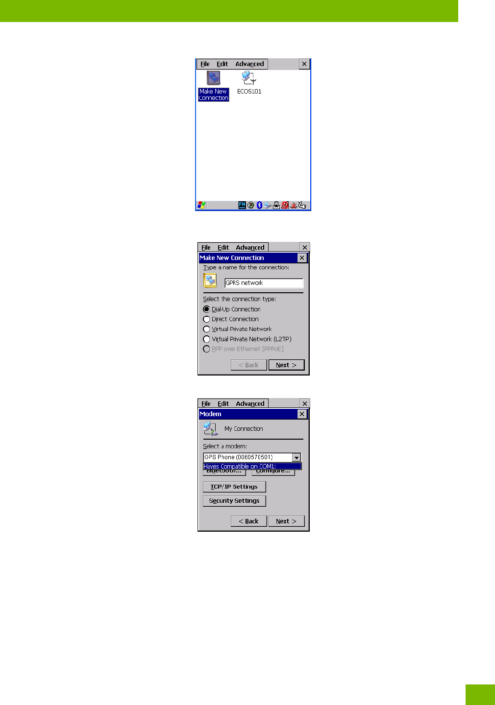
Chapter 4: Configuration
The Bluetooth GPRS WAN Connection
51
Psion 8516 Vehicle-Mount Computer User Manual
5. Tap on Make New Connection.
6. In the Make New Connection dialog box, choose Dial-Up Connection. Enter a name for your GPRS
network connection.
7. Ch oos e t h e Next button to display the Modem dialog box.
8. In the drop-down menu labelled Select a modem, choose the name of the modem with which you
want to connect, and then choose the Configure button to display the Device Properties dialog
box.
The 8516 communicates via Bluetooth to your Bluetooth equipped cellular telephone and retrieves the
parameters for the Device Properties dialog box. 8516 then disconnects.
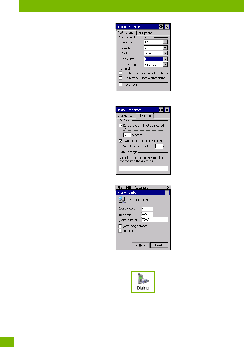
Chapter 4: Configuration
The Bluetooth GPRS WAN Connection
Psion 8516 Vehicle-Mount Computer User Manual
52
9. Under the Call Options tab, turn off Cancel the call if not connected within, and press [ENTER]
to save your changes.
10. In the Modem dialog box, choose the Next button to display the Phone Number dialog box.
The phone number you enter is network carrier dependent. Once you’ve specified all the necessary
information, choose the Finish button.
11. In the Control Panel, choose the Dialing icon.
12. The values in the Dialing Properties dialog box need to be edited according to your network carrier
specifications.
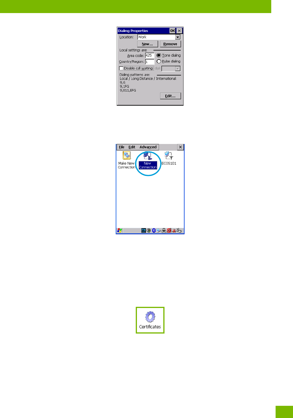
Chapter 4: Configuration
Certificates
53
Psion 8516 Vehicle-Mount Computer User Manual
Once you’ve edited this dialog box to reflect your network carrier requirements, press [ENTER] to
save your changes.
13. At this point, return to the Control Panel, and choose the Network and Dial-up Connections icon.
14. In the network connection window, the new network configuration—in this case, New Connection is
displayed. Tap on the new icon.
When you tap on your new connection, an onscreen message indicates the status of your connection: con-
nected, disconnected, error messages, and so on.
4.5 Certificates
This program provides access to the Certificates Manager and Stores. The Certificates Manager displays
the certificates in the Windows Certificates Store, and allows you to import, delete, and view these certifi-
cates. 8516 checks that the certificate has been digitally signed by a certification authority that the 8516
explicitly trusts. This option is used in conjunction with 802.1x authentication to enhance 8516 security.
•In the Control Panel, choose the Certificates icon.
Your 8516 has certificates preinstalled in the computer. My Certificates is the repository for the device’s
personal certificate store, Other Authorities is the repository for the intermediate certificate store, and
Trusted Authorities is the repository for the Trusted Root certificate store.
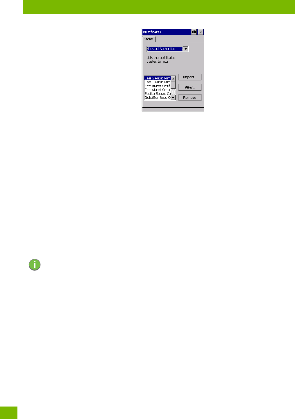
Chapter 4: Configuration
Data Transfer between 8516 and a PC
Psion 8516 Vehicle-Mount Computer User Manual
54
You can import or remove certificates, and view certificate information for any listing, including names,
dates, serial numbers, etc.
For a detailed description about Certificate setup for both the server and client-side devices (8516 Vehi-
cle-Mount Computers), refer to the following website:
http://www.microsoft.com/windowsserver2003/techinfo/overview/security.mspx
4.6 Data Transfer between 8516 and a PC
Data transfer options vary slightly depending on the type of operating system installed in your PC.
For Windows XP SP2 operating systems or earlier, Microsoft® ActiveSync® connectivity software can be
used to connect your 8516 to PCs.
If the Windows Vista® , Windows 7 or later, operating system is installed in your PC, ActiveSync is not re-
quired to transfer data between your 8516 and your PC.
You can connect to a PC with a cable and:
• View 8516 files from Windows Explorer.
• Drag and drop files between the 8516 and the PC in the same way that you would between PC drives.
• Back up 8516 files to the PC, restore them from the PC to the Vehicle-Mount again, etc.
4.6.1 Using Microsoft ActiveSync
To install ActiveSync, follow the step-by-step instructions provided with the program’s setup wizard. For de-
tails, go to the following website and type the name into the search box:
http://www.microsoft.com/downloads/en/default.aspx
4.6.2 Using Windows Mobile Device Center
If you are running Windows Vista, Windows 7, or later, your data transfers do not require ActiveSync.
Instead, you will need to download Windows Mobile Device Center. For instructions, go to the following
website and type the name into the search box:
http://www.microsoft.com/downloads/en/default.aspx
To transfer data between your PC and your Vehicle-Mount:
•Tap on Start>Computer to display the drives. The 8516 will be visible here.
• Open drives, files and folders as you would on your PC.
Note: If you use a serial port to connect devices like the 8516 to your desktop computer, the connection
may not succeed because ActiveSync has trouble connecting at non-default baud rates.
To work around this problem, set the ActiveSync baud rate on the desktop to use the same baud
rate as the device. You can set the baud rate by editing the registry on the desktop host computer,
as detailed in the steps outlined at the following website:
http://suppo.microsoft.com/kb/324466
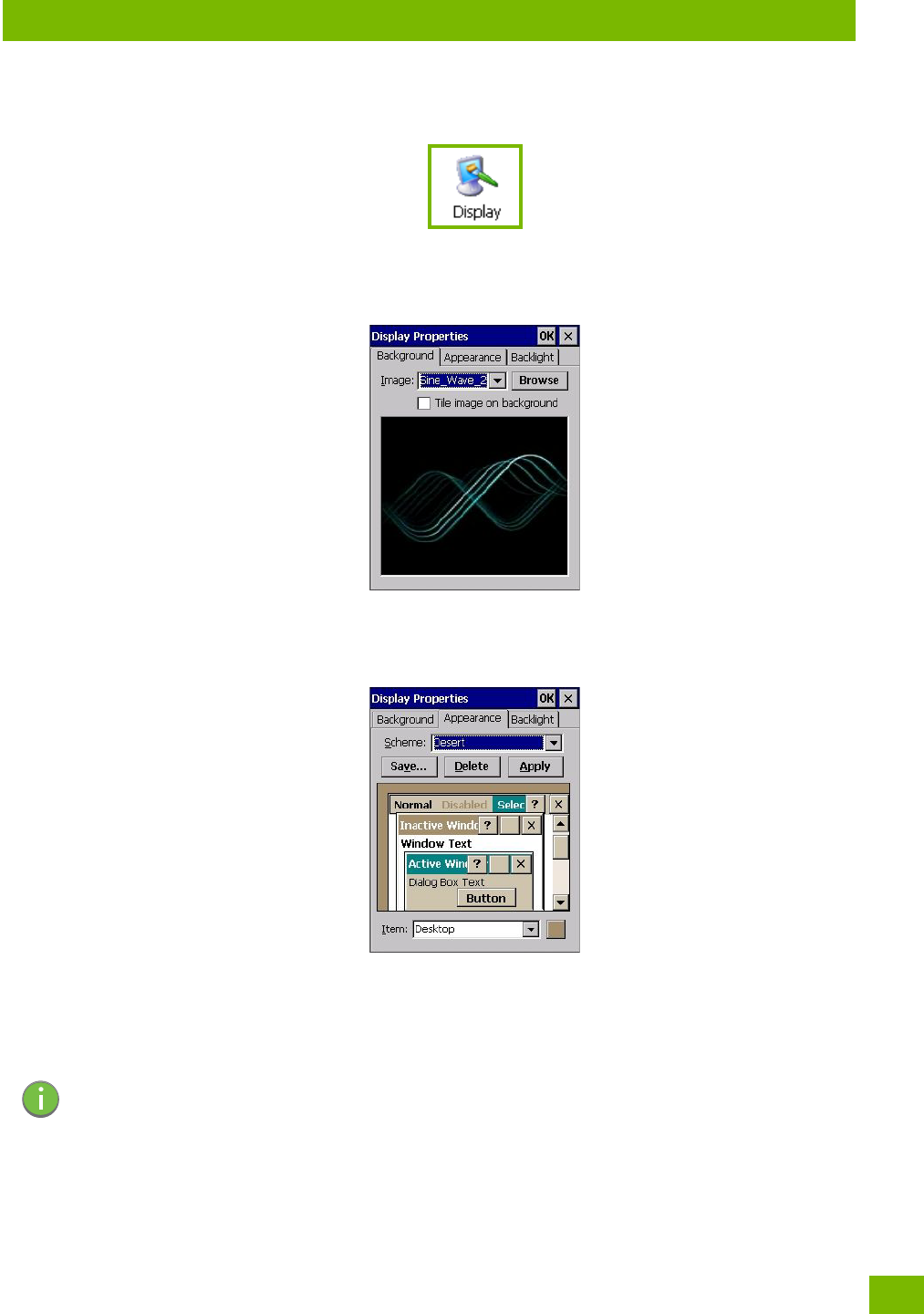
Chapter 4: Configuration
Display Properties
55
Psion 8516 Vehicle-Mount Computer User Manual
4.7 Display Properties
•In the Control Panel, choose the Display icon.
4.7.1 Background
•In the Display Properties dialog box, open the Background tab. This dialog box allows you to customize
your background image.
4.7.2 Appearance
•In the Display Properties dialog box, open the Appearance tab. This dialog box allows you to customize
the display colour scheme.
4.7.3 Backlight
The backlight is activated for a configurable amount of time. The Display Properties dialog box in the
Control Panel allows you to specify the intensity of the backlight along with how long the backlight remains
on when the unit is not in use (no key press, scanner trigger, etc.).
•In the Display Properties dialog box, open the Backlight tab.
Note: Keep in mind that this option may be restricted to supervisory use only.
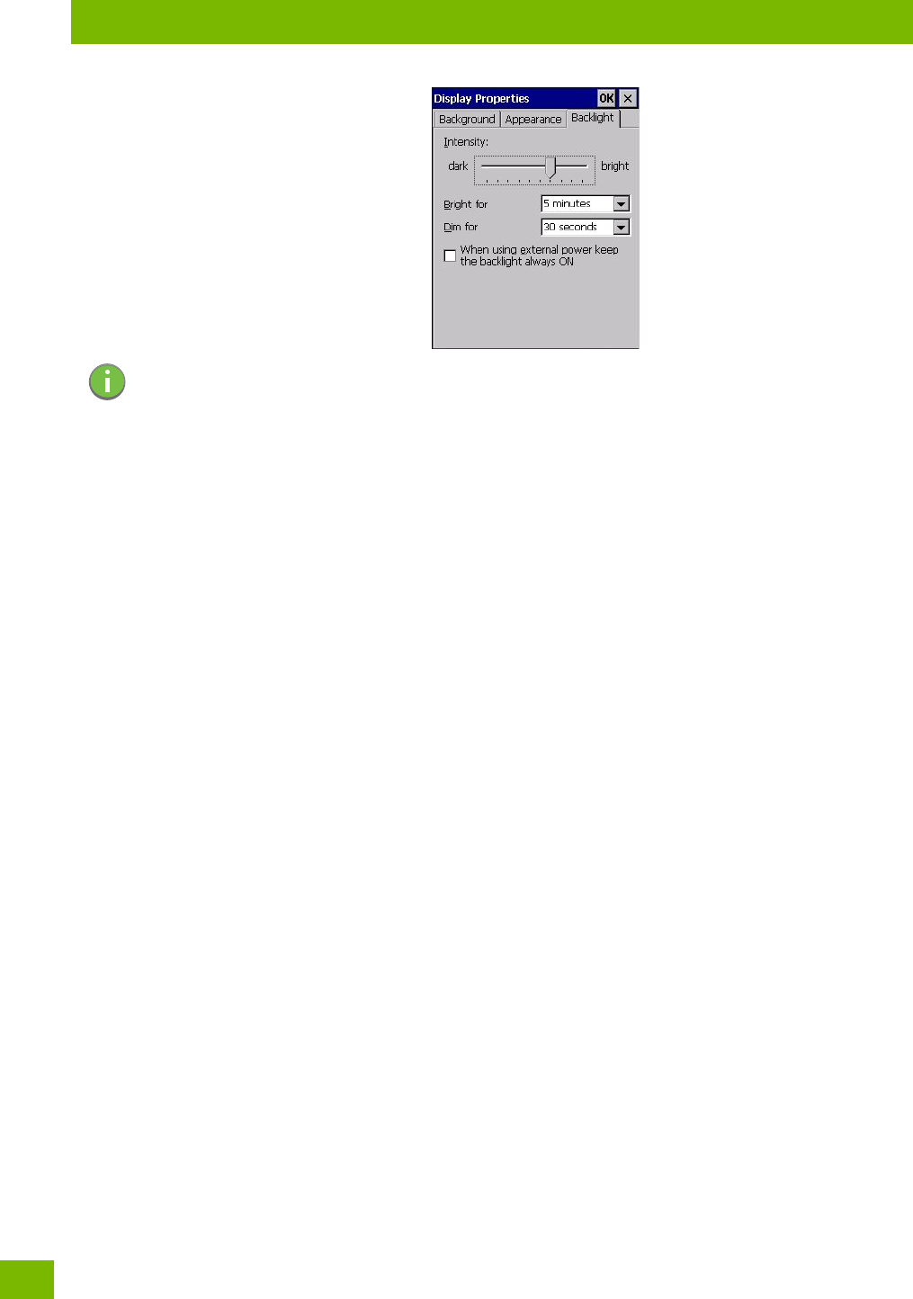
Chapter 4: Configuration
Backlight
Psion 8516 Vehicle-Mount Computer User Manual
56
Intensity
This parameter is used to adjust the light intensity of the 8516 backlight. Sliding the bar to the left lowers
the light intensity, and sliding it to the right raises the intensity.
Bright For
The value chosen from this drop-down menu determines the duration of time that the backlight stays on at
the configured intensity after the last user action (keypress, scan trigger).
Dim For
The value chosen from this drop-down menu determines the duration of time that the backlight stays on at
half the configured intensity (dimmed backlight) after expiration of the Bright For delay and as long as no
user action takes place (such as a keypress or scan trigger). At the expiration of the Dim For duration, the
display backlight shuts off.
External Power Checkbox
When you select the checkbox next to When using external power keep the backlight always ON, the back-
light remains ON at the configured intensity when the 8516 is operating with external power (not battery
power). If the 8516 is drawing power from its battery, this option is ignored and the other parameters
defined in Display Properties dialog box take effect.
Note: Backlight changes take effect immediately. You do not need to reset the unit.
To maximize battery run time, keep the display backlight brightness and active durations as
low as possible.
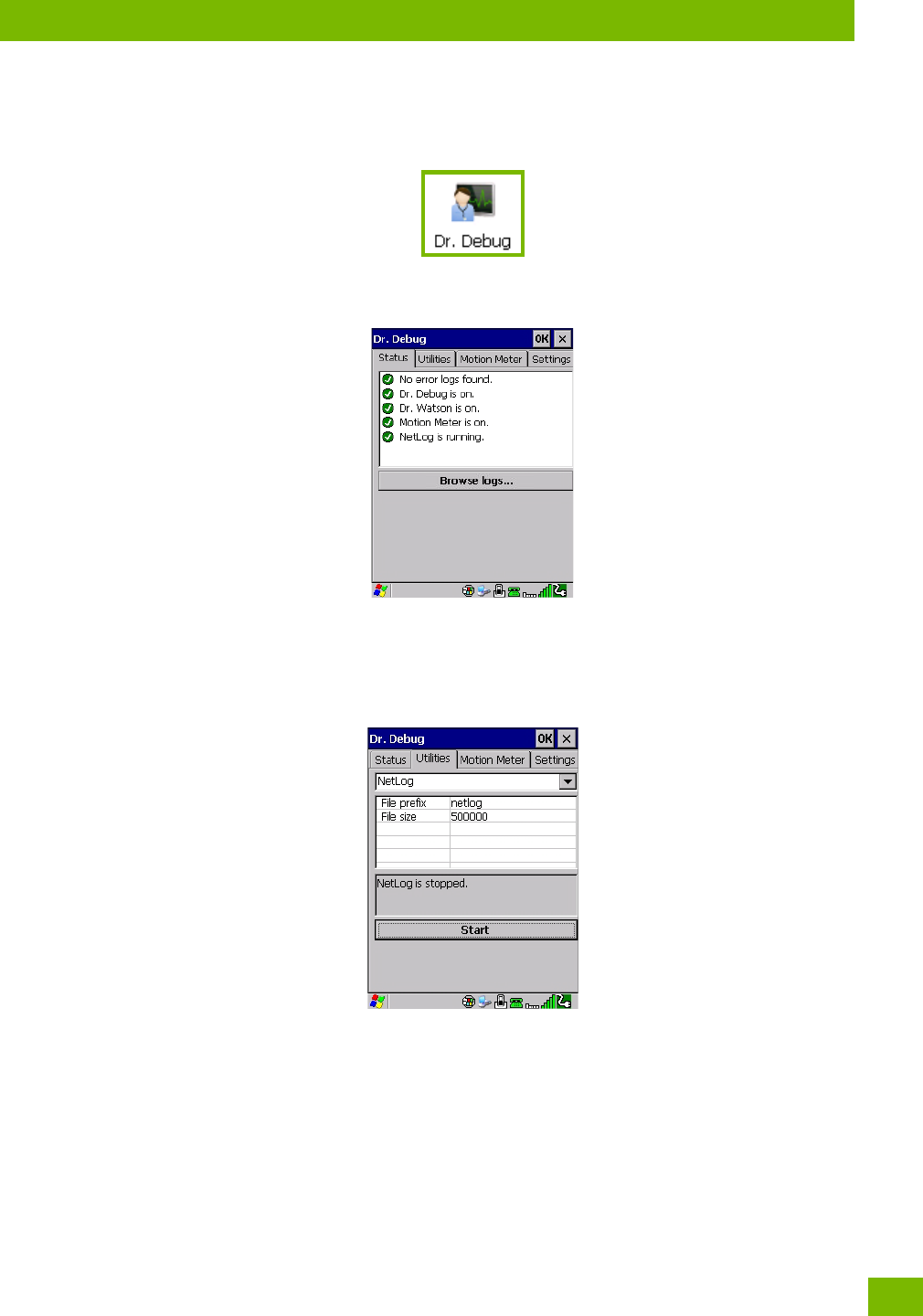
Chapter 4: Configuration
Dr. Debug
57
Psion 8516 Vehicle-Mount Computer User Manual
4.8 Dr. Debug
Dr. Debug is an error diagnostic and troubleshooting tool.
•Tap on Start>Settings>Control Panel. Tap on the Dr. Debug icon.
4.8.1 Status
This tab indicates the status (on/off) of the debug engines. Tapping on Browse logs displays error logs for
your review. The logs should be used as reference when working with Psion Technical Support personnel.
4.8.2 Utilities
The Utilities tab is used to log network traffic. When you tap on the Start button, debug data is collected so
that, if necessary, it can be forwarded to a Psion technician for evaluation.
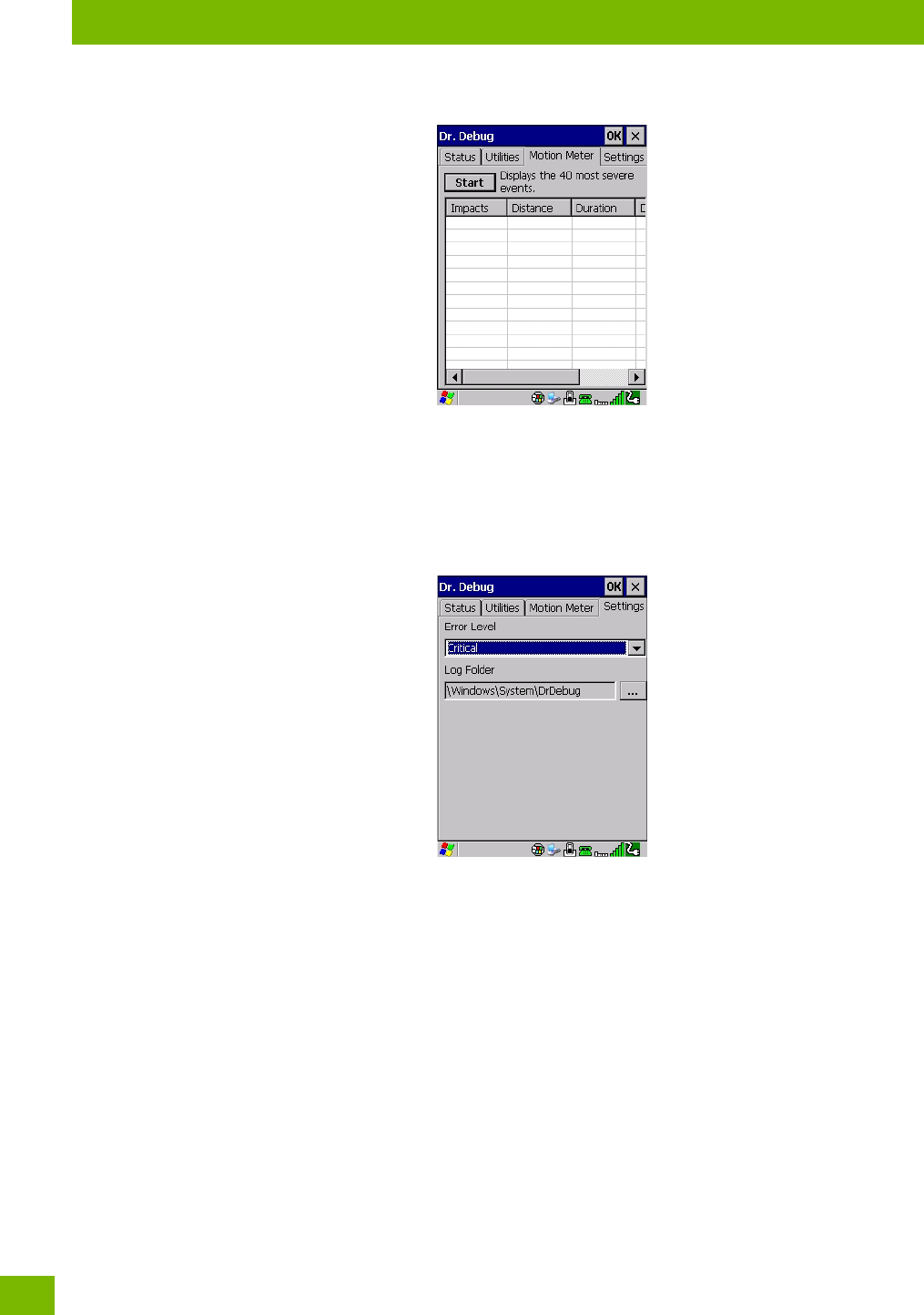
Chapter 4: Configuration
Motion Meter
Psion 8516 Vehicle-Mount Computer User Manual
58
4.8.3 Motion Meter
Tapping on the Start button enables the Motion Meter feature. Once enabled, this applet records the
number of impacts the 8516 has sustained, the distance of the fall in meters, the duration in 10ths of a
second, and the date and time that the event occurred. The top 40 events are logged in a non-volatile loca-
tion and can be used for diagnostic purposes by Psion or the site administrator.
4.8.4 Settings
•Choose an Error Level from the drop-down menu.
• To change the location where debug information will be stored, tap on the button to the right of the
Log Folder option.
4.9 Error Reporting
Error Reporting allows you to enable or disable Microsoft error reporting prompts.
•Tap on Start>Settings>Control Panel>Error Reporting icon to access your options.
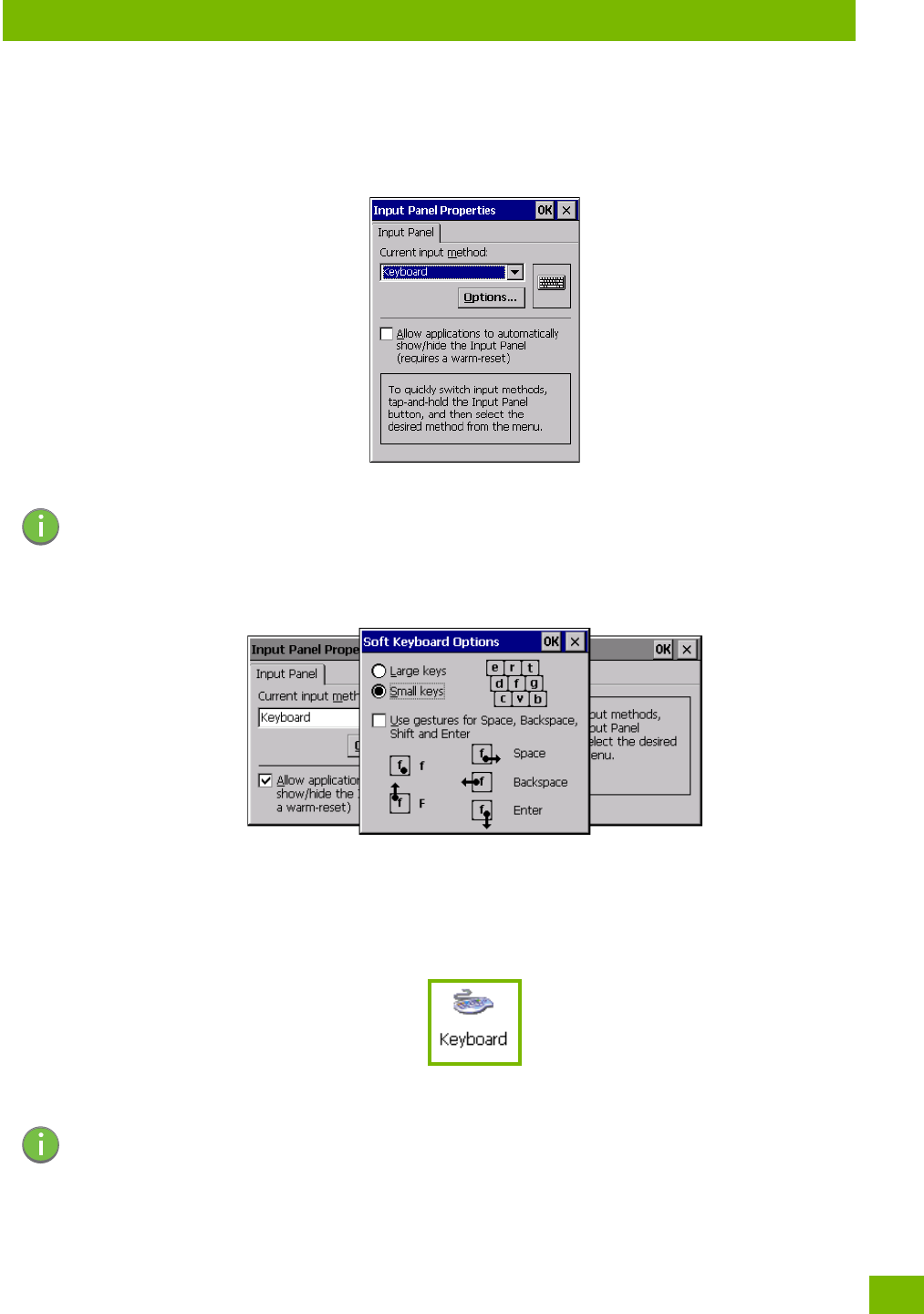
Chapter 4: Configuration
Keyboard Properties
63
Psion 8516 Vehicle-Mount Computer User Manual
To customize the appearance and behaviour of the soft keyboard:
Tap on t he Input Panel icon in the Control Panel.
Figure 4.2 Input Panel Properties
• Tap on the Options button to change the appearance of your soft keyboard.
Figure 4.3 Soft Keyboard Options
4.11.1 Keyboard Properties
This icon displays the Keyboard Properties dialog box in which you can adjust the repeat rate of the keys,
the intensity of the keyboard backlight and the behaviour of the [FN] and [SYM] modifier keys. This dialog
box also allows you to define macro keys and Unicode characters.
•In the Control Panel, choose the Keyboard icon.
4.11.1.1 Key Repeat
•In the Keyboard Properties dialog box, open the Repeat tab.
Note: You can also display this dialog box by double-tapping on the Input icon in the far-right cor-
ner of the taskbar.
Note: These settings apply when a key is held down continuously.
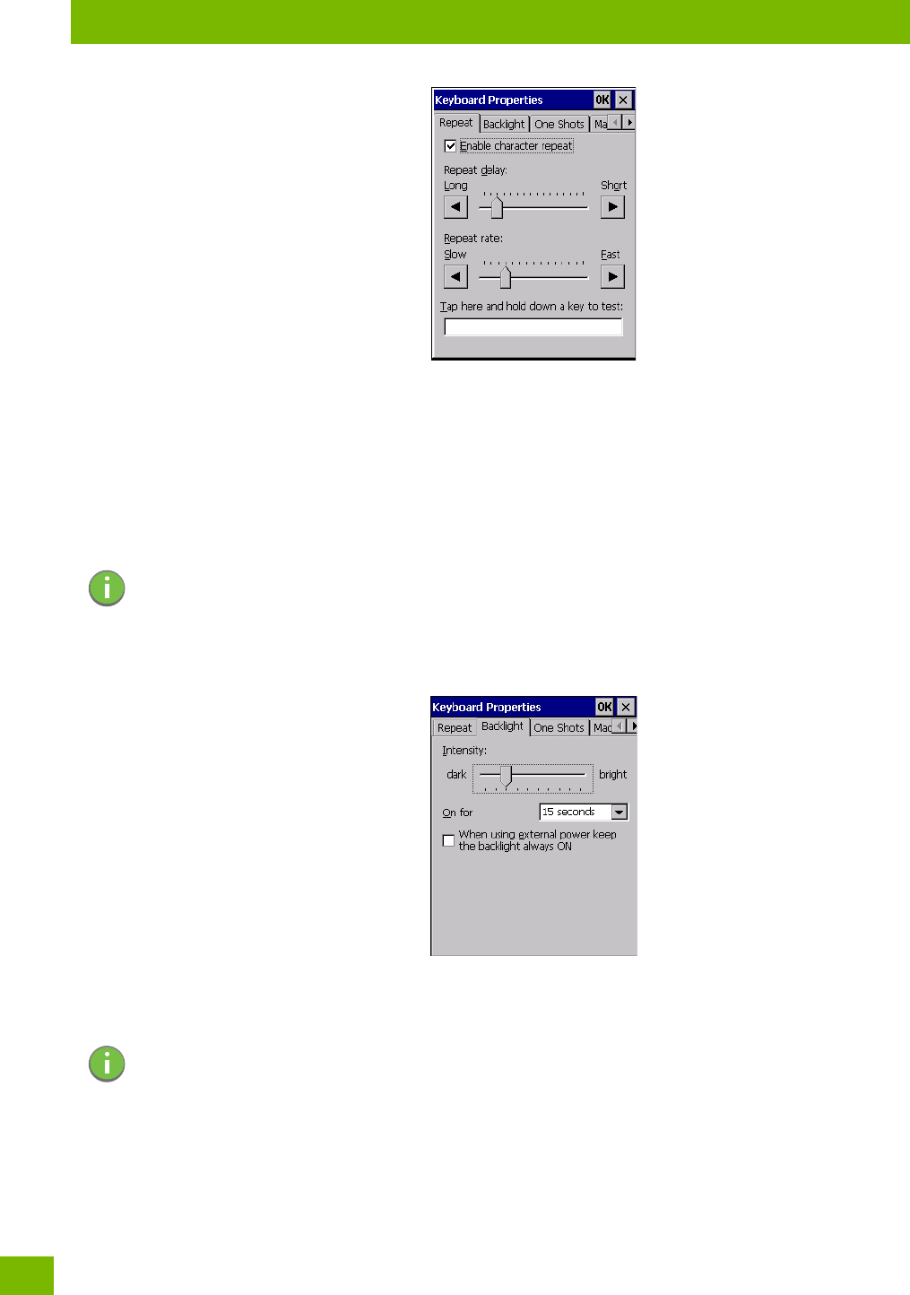
Chapter 4: Configuration
Keyboard Properties
Psion 8516 Vehicle-Mount Computer User Manual
64
Repeat Delay
The value assigned for this parameter determines the delay in milliseconds between repeat characters.
Sliding the Repeat Delay bar to the left increases the delay between key repeats, and sliding the bar to the
right shortens the repeat delay time.
Repeat Rate
The value assigned for the Repeat Rate parameter determines how quickly the key you press repeats and is
measured in characters per second (cps). Sliding the bar to the left slows the repeat rate, and sliding the bar
to the right increases the repeat rate.
4.11.1.2 Keyboard Backlight
•In the Keyboard Properties dialog box, open the Backlight tab.
Intensity
This parameter is used to adjust the light intensity of the 8516 keyboard backlight. Sliding the bar to the left
darkens the keyboard backlight intensity, and sliding it to the right lightens the intensity.
ON For
The value chosen from this drop-down menu determines the duration of time that the keyboard backlight
stays on after the last user action (keypress or scan trigger).
Note: Use the field at the bottom of this dialog box to test the repeat delay and rate settings
you’ve chosen.
Note: The keypad backlight maximum brightness will decrease over time as it ages. Use mid-range
intensity settings when possible to extend the backlight lifespan. When the backlight starts
to dim, use this parameter to make it brighter.
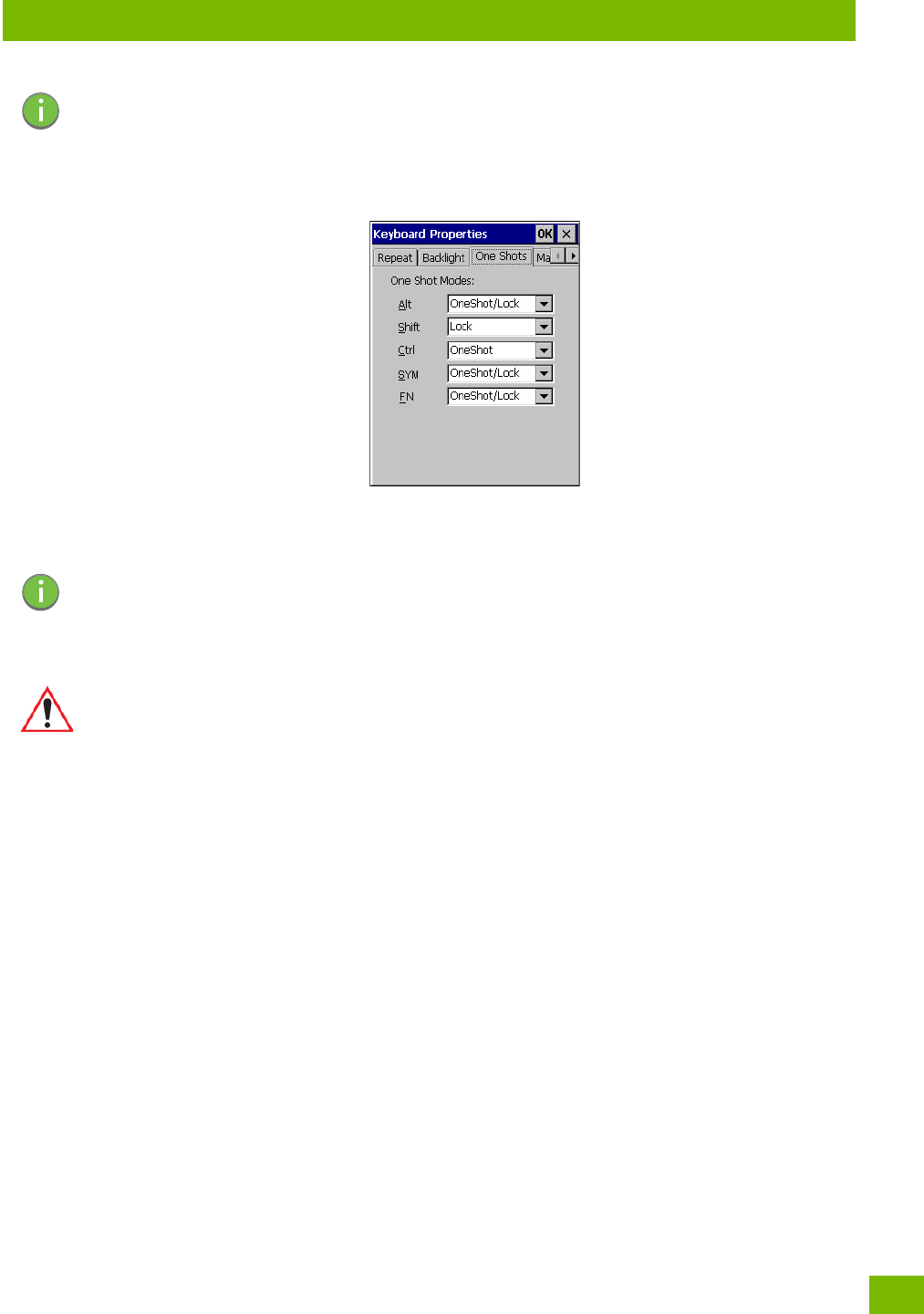
Chapter 4: Configuration
Keyboard Properties
65
Psion 8516 Vehicle-Mount Computer User Manual
4.11.1.3 Keyboard One Shot Modes
•In the Keyboard Properties dialog box, open the One Shots tab.
The options in this tab allow you to determine how modifier keys on your 8516 behave. For each modifier
key—[ALT], [SHIFT], [CTRL], [FN], and [SYM]—you have the following options in the drop-down menu: Lock,
OneShot, and OneShot/Lock.
Lock
If you choose Lock from the drop-down menu, pressing a modifier key once locks it ‘on’ until you press the
modifier key a second time to unlock or turn it off.
OneShot
If you choose OneShot, the modifier key remains active only until the next key is pressed.
OneShot/Lock
OneShot/Lock allows you to combine these functions. When you choose this option and you press the mod-
ifier key once, it remains active only until the next key is pressed.
If you press the modifier key twice, it is locked ‘on’, remaining active until the modifier key is pressed a third
time to turn it ‘off’.
4.11.1.4 Keyboard Macro Keys
•In the Keyboard Properties dialog box, open the Macros tab.
Note: Tapping in the checkbox next to ‘When using external power, keep the backlight always
ON’ forces the keypad backlight to remain on when the unit is operating with external power.
Note: Keep in mind that checking the taskbar lets you know whether or not these keys are locked
on. For example, if the [FN] key is locked ‘on’, the taskbar at the bottom of the screen dis-
plays it underlined. If this key is displayed without the underline in the taskbar, you’ll know
that the key is not locked. It will become inactive following a key press.
Important: Once you’ve assigned a One Shot mode to a modifier key, you need to tap on the
OK button at the top of the tab to activate your selection.
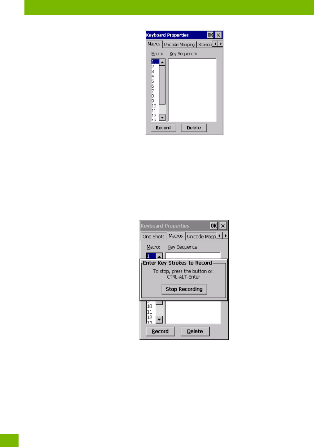
Chapter 4: Configuration
Keyboard Properties
Psion 8516 Vehicle-Mount Computer User Manual
66
A macro has 200 programmable characters (or “positions”). The macro keys can be programmed to replace
frequently used keystrokes, along with the function of executable keys including [ENTER], [BACKSPACE]
and [DEL] ([FN]-[BACKSPACE]), function keys and arrow keys.
Recording and Saving a Macro
You can program up to 6 physical macro keys, depending on your keyboard layout. You can also increase
the number of virtual macro keys up to 15 using Scancode Remapping (for details, see “Scancode Remap-
ping” on page 68).
•In the Macro menu highlight a macro key number, for example macro 1, to assign a macro to macro key
[M1]. Choose the Record button.
A message screen is displayed instructing you to Enter Key Strokes to Record.
• Type the macro sequence you want to assign to the Macro key. You can type text and numbers, and you
can program the function of special keys into a macro.
• When you’ve finished recording your macro sequence, press the key sequence: [CTRL] [ALT] [ENTER],
or choose the Stop Recording button.
A new screen ‘Verify Macro’ displays the macro sequence you created. The Save button is highlighted.
•Press [ENTER] to save your macro, or highlight CANCEL and press [ENTER] to discard it.
Executing a Macro
To execute a macro:
• Press the macro key to which you’ve assigned the macro.
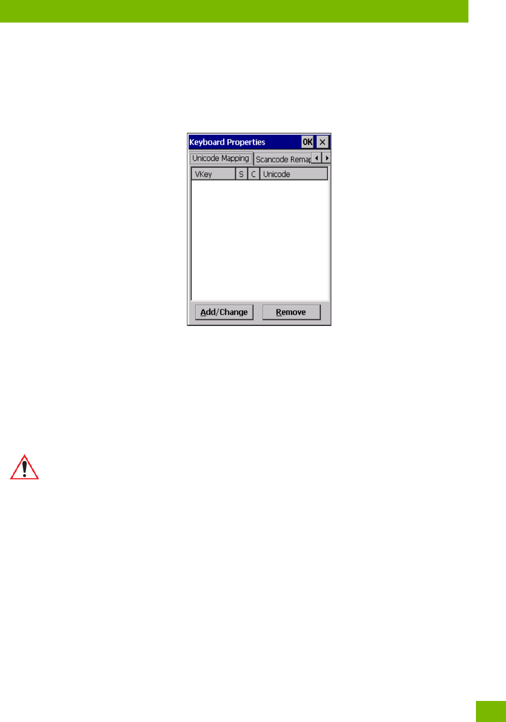
Chapter 4: Configuration
Keyboard Properties
67
Psion 8516 Vehicle-Mount Computer User Manual
Deleting a Macro
To delete a macro:
•In the Macros tab, highlight the macro number you want to delete.
• Choose the Delete button.
4.11.1.5 Unicode Mapping
•In the Keyboard Properties dialog box, open the Unicode Mapping tab.
The Unicode Mapping tab is used to map combinations of virtual key values and [CTRL] and [SHIFT] states
to Unicode™ values. This tab shows the configured Unicode character along with the Unicode value. For ex-
ample, the sample screen above shows “a (U+0061)” indicating that the character “a” is represented by the
Unicode value “0061”, and so on. Keep in mind that Unicode configurations are represented as hexidecimal
rather than decimal values.
All user-defined Unicode mappings are listed in the Unicode Mapping tab in order of virtual key value, and
then by order of the shift state. If a Unicode mapping is not listed, the Unicode mapping is mapped to the
default Unicode value.
Adding and Changing Unicode Values
• Choose the Add/Change button.
Important: Changes to Unicode mappings are not saved until you exit the Keyboard Proper-
ties dialog box.

Chapter 4: Configuration
Keyboard Properties
Psion 8516 Vehicle-Mount Computer User Manual
68
• Highlight a value in the Unicode mapping list. In the sample screen above, a value will be assigned to
virtual key 0 (VK 0).
• Position the cursor in the Unicode Mapping field, and type a Unicode value for the highlighted key.
Removing Unicode Values
•In the Unicode Mapping tab, highlight the item you want to delete, and choose the Remove button.
4.11.1.6 Scancode Remapping
A scancode is a number that is associated with a physical key on a keyboard. Every key has a unique scan-
code that is mapped to a virtual key, a function or a macro. Scancode Remapping allows you to change the
functionality of any key on the keyboard. A key can be remapped to send a virtual key (e.g. VK_F represents
the ‘F’ key; VK_RETURN represents the [ENTER/Power] key, etc.), perform a function (e.g. turn the scanner
on, change volume, etc.) or run a macro.
There are three different tables of scancode mappings: the Normal table, the FN table and the SYM table.
The Normal table defines unmodified key presses; the FN table defines key presses that occur when the
[FN] modifier is on; the SYM table defines key presses that occur when the [SYM] modifier is on. The default
mappings of these scancodes can be overwritten for each of these three tables using the Scancode Remap-
ping tab accessed from the Keyboard Properties dialog box.
Note: To add a shifted state, [SHIFT] and/or [CTRL], press [TAB] to position the cursor in the
checkbox next to ‘SHIFT Pressed’ and/or ‘CTRL Pressed’. Press [SPACE] to select the shift
state you want to assign.
Note: When using the Mobile Devices SDK Developers' Guide (PN 8100016), note that the
[ORANGE] key is interchangeable with the [SYM] key. Similarly, in the context of the scan-
code mapping tables, ‘Orange’ is interchangeable with ‘SYM’.
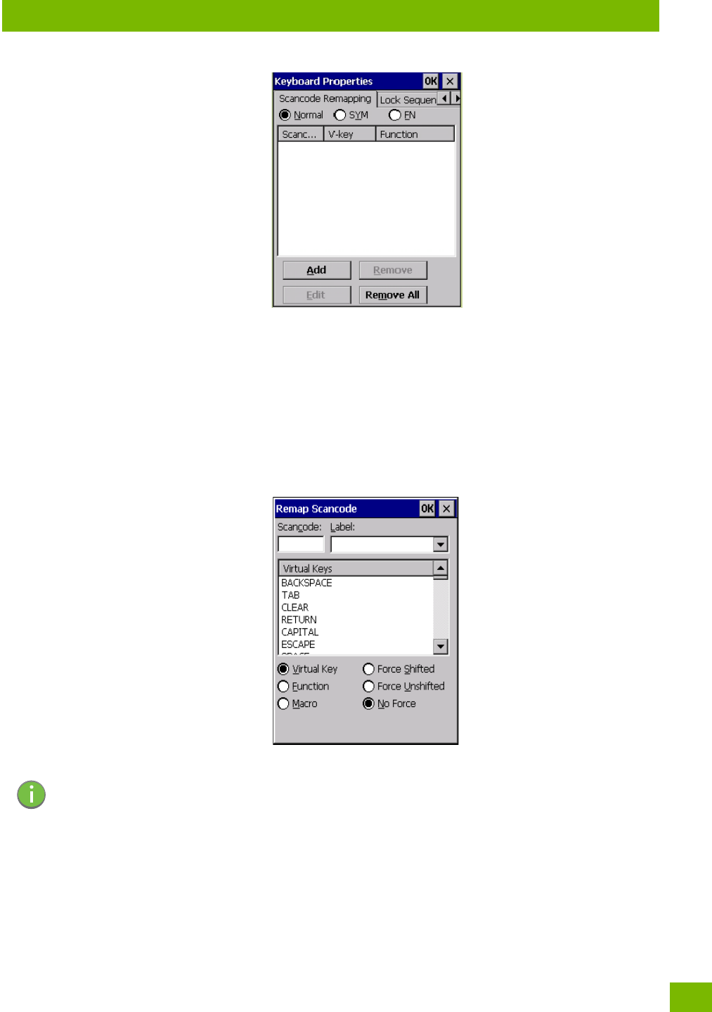
Chapter 4: Configuration
Keyboard Properties
69
Psion 8516 Vehicle-Mount Computer User Manual
The first column in the Scancode Remapping tab displays the scancodes in hexidecimal. If the scancode is
remapped to a virtual key, that virtual key is displayed in the next column labelled ‘V-Key’. A virtual key that
is ‘Shifted’ or ‘Unshifted’ is displayed in the third column labelled ‘Function’.
If the scancode is remapped to a function or a macro, the first and second columns remain blank while the
third column contains the function name or macro key number (e.g., Macro 2).
Adding a Remap
To add a new remapping:
• Choose the Add button at the bottom of the dialog box.
The Remap Scancode dialog box is displayed.
• Type the scan code in hexidecimal in the field labelled Scancode.
Virtual Key, Function and Macro
The radio buttons at the bottom of the dialog box allow you to define to what the scan code will be rema-
pped: Virtual Key, Function or Macro.
When Virtual Key is selected, you can choose to force [SHIFT] to be on or off when the virtual key is sent. If
No Force is selected, the shift state is dependent on whether the shift state is on or off at the time the
virtual key is sent.
When Function is selected, a list of valid functions appears in the dialog box.
When Macro is selected, the macro keys available on your unit are listed in the dialog box.
Note: The Label field displays the default function of the scancode you are remapping.
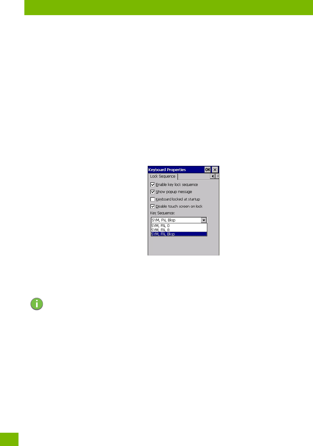
Chapter 4: Configuration
Keyboard Properties
Psion 8516 Vehicle-Mount Computer User Manual
70
•Choose Virtual Key, Function or Macro.
• Choose a function from the Function list in the dialog box, and tap on OK.
Editing a Scancode Remap
To edit a scancode:
•In the Scancode Remapping tab, tap on the remap you want to edit.
• Tap on the Edit button, and make the appropriate changes.
•Tap on OK to save your changes.
Removing a Remap
To delete a remap:
•In the Scancode Remapping tab, highlight the scancode you want to delete, and tap on the Remove
button.
•Tap on OK.
4.11.1.7 Lock Sequence
The Lock Sequence menu allows you to lock the 8516 keyboard to prevent keys from being
pressed accidentally.
• To lock the keyboard, tap in the checkbox next to Enable key lock sequence.
• Tap in the checkbox next to Keyboard locked at startup.
•In the Key sequence drop-down menu, choose the key sequence you will need to type to unlock the
keyboard.
A locked keyboard icon is displayed in the softkey bar when the keyboard is locked.
Note: It is useful to leave the ‘Show popup message’ enabled (default) so that anyone attempting to
use the keyboard will see the key sequence they will need to enter to unlock the keyboard dis-
played on the screen.
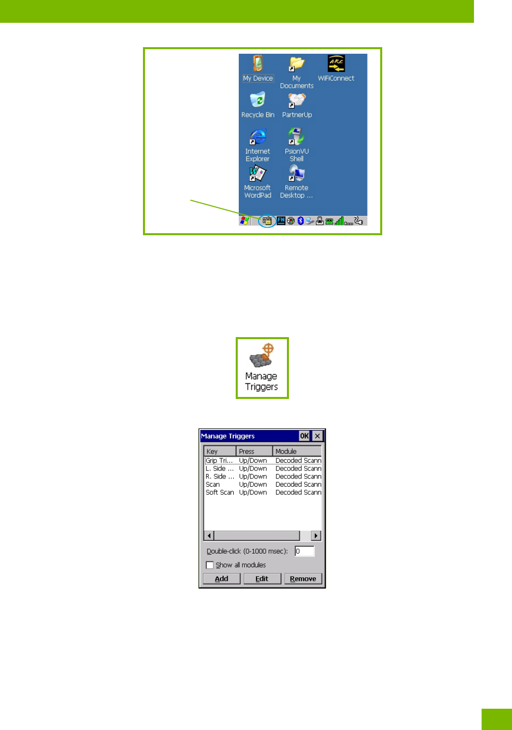
Chapter 4: Configuration
Manage Triggers
71
Psion 8516 Vehicle-Mount Computer User Manual
• Type the key sequence to unlock the keyboard.
4.12 Manage Triggers
Allows users to configure how barcode scanners and other devices such as RFID readers are triggered. You
can configure the trigger ID for each trigger button for both single- and double-click, and the double-click
time.
•In the Control Panel, choose the Manage Triggers icon.
•In the Manage Triggers screen you’ll see a list of trigger mappings.
4.12.1 Trigger Mappings
A trigger mapping is an association between a particular key on the keyboard and a driver or application,
the module(s)—sometimes referred to as “trigger consumer(s)”—of the trigger source. Along with keyboard
keys, the external trigger (scan button) is software-based. When the specified key is pressed, the owner (for
example, a decoded scanner) is sent a message.
Locked Keyboard
Icon
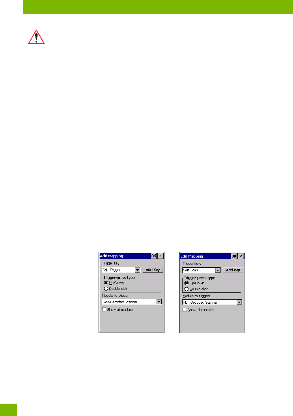
Chapter 4: Configuration
Add and Edit Trigger Mapping
Psion 8516 Vehicle-Mount Computer User Manual
72
Double-Click
When a key is pressed and released, then pressed again within the configured time (between 0 to
1000 msec), a double-click occurs. See also “Trigger-Press Type” on page 73.
Show All Modules
By default, the trigger mapping list only shows active mappings. Mappings for drivers or applications that
are not currently active are not normally displayed. By checking this checkbox, all mappings, both active
and inactive, are displayed.
Add
Tapping this button brings up the Add Mapping dialog (see page 72), so that you can add new trigger map-
pings.
Edit
Tapping this button brings up the Edit Mapping dialog (see page 72), so that you can edit existing trigger
mappings.
Remove
Tapping this button removes an existing mapping.
OK
The OK button in the top right of the Manage Triggers screen saves all changes made. If the cancel button X
is tapped instead, or the [ESC] key is pressed, all changes made will be discarded.
4.12.2 Add and Edit Trigger Mapping
These dialogs allow you to add and edit trigger mappings.
Trigger Key
This drop-down list allows you to specify the source of the trigger events, such as the Soft Scan, Left Scan,
etc., for the trigger module selected.
Important: It is not possible to have two or more identical mappings—for example [F1] cannot
be mapped to the Non-Decoded Scanner twice—even if the trigger type is
different.
A keyboard key that is used as a trigger source will no longer generate key data,
or perform its normal function. For example, if the space button is used as a
trigger source, it will not be able to send space characters to applications.
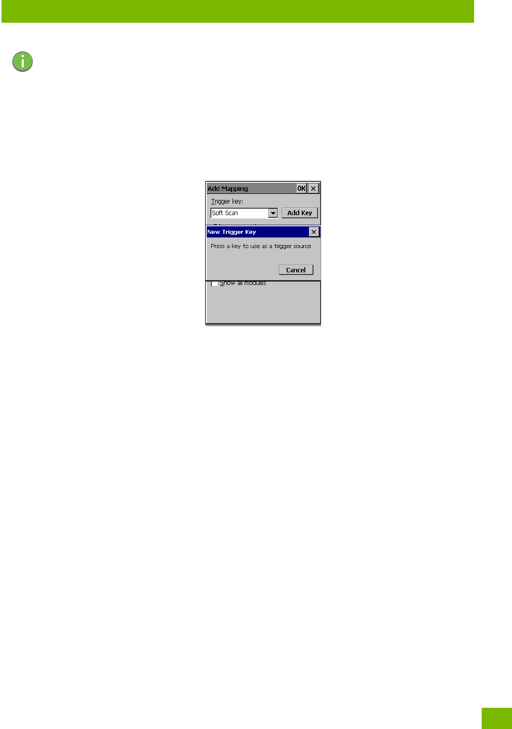
Chapter 4: Configuration
Microphone
73
Psion 8516 Vehicle-Mount Computer User Manual
Add Key
Only existing trigger sources are shown in the Source combo-box. To add a new source to this list, tap on
the Add Key button. A dialog will pop up and allow you to select the keyboard key to use as a trigger
source.
Trigger-Press Type
You can enable either an Up/Down or Double Click response to a trigger press. Normally, when a trigger
(keyboard key, etc.) is pressed and released, a “trigger down” event is sent to the “owner”—that is, the appli-
cation receiving the trigger press information—followed by a “trigger up”. If Double Click is chosen in this
menu, when the trigger is pressed, released, and then pressed again, a “double-click” event will have oc-
curred. If a mapping with the type Up/Down has also been configured for the same source, it will only
receive the first set of trigger events.
Module Trigger
This identifies the driver or application receiving the trigger presses.
Show All Modules
By default, inactive owners are not shown. By checking this checkbox, all owners, both active and inactive,
are displayed.
4.13 Microphone
•In the Control Panel, choose the Microphone icon. Use this dialog box to adjust the gain for the specific
microphones associated with your Vehicle-Mount.
Note: It is possible to map the same source to different modules (trigger consumers)—for example,
to both the Imager and Non-Decoded Scanner. If so, both devices/operations will occur
simultaneously. This is not recommended in most cases, especially with devices such as
Imagers or RFID Readers.
It is also possible to map different sources to the same module (trigger consumer)—for
example, two different trigger keys can be mapped to the RFID File System.
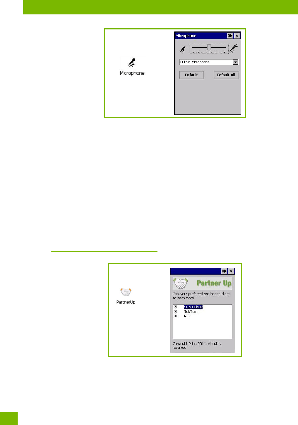
Chapter 4: Configuration
Open TekTerm
Psion 8516 Vehicle-Mount Computer User Manual
74
• Tap on the drop-down menu, and choose the microphone for which you want to adjust the gain.
• Slide the microphone tab to the left to decrease the gain and to the right to increase the gain.
Tapping on the Default button sets the current microphone you’ve chosen to the default gain. Tapping on
Default All sets all microphones listed to their default gain.
4.14 Open TekTerm
Open TekTerm is a powerful emulation application ideally suited for real time data transaction applications
associated with mainframes and servers. The 8516 includes unique features that support Open TekTerm, a
Psion application that has the ability to maintain multiple simultaneous sessions with a variety of host com-
puters. For detailed information, please refer to the Open TekTerm Software User Manual, PN 8000073.
4.15 PartnerUp
This app displays a number of pre-loaded applications. Tapping on an app in the list takes you to an associ-
ated web site.
The operator can then install the application. If a license is required, it can be obtained by sending an e-mail
to the software license mailbox or by contacting a Sales Representative from the Psion contact web page.
www.psion.com/us/about/contact_psion-offices.htm
Additional pieces of software such as a server must be obtained through Psion.
Tapping on a preloaded client in this screen displays a drop-down menu from which the operator can
choose from an array of related options. In the example following, Stay-Linked Documentation was chosen.
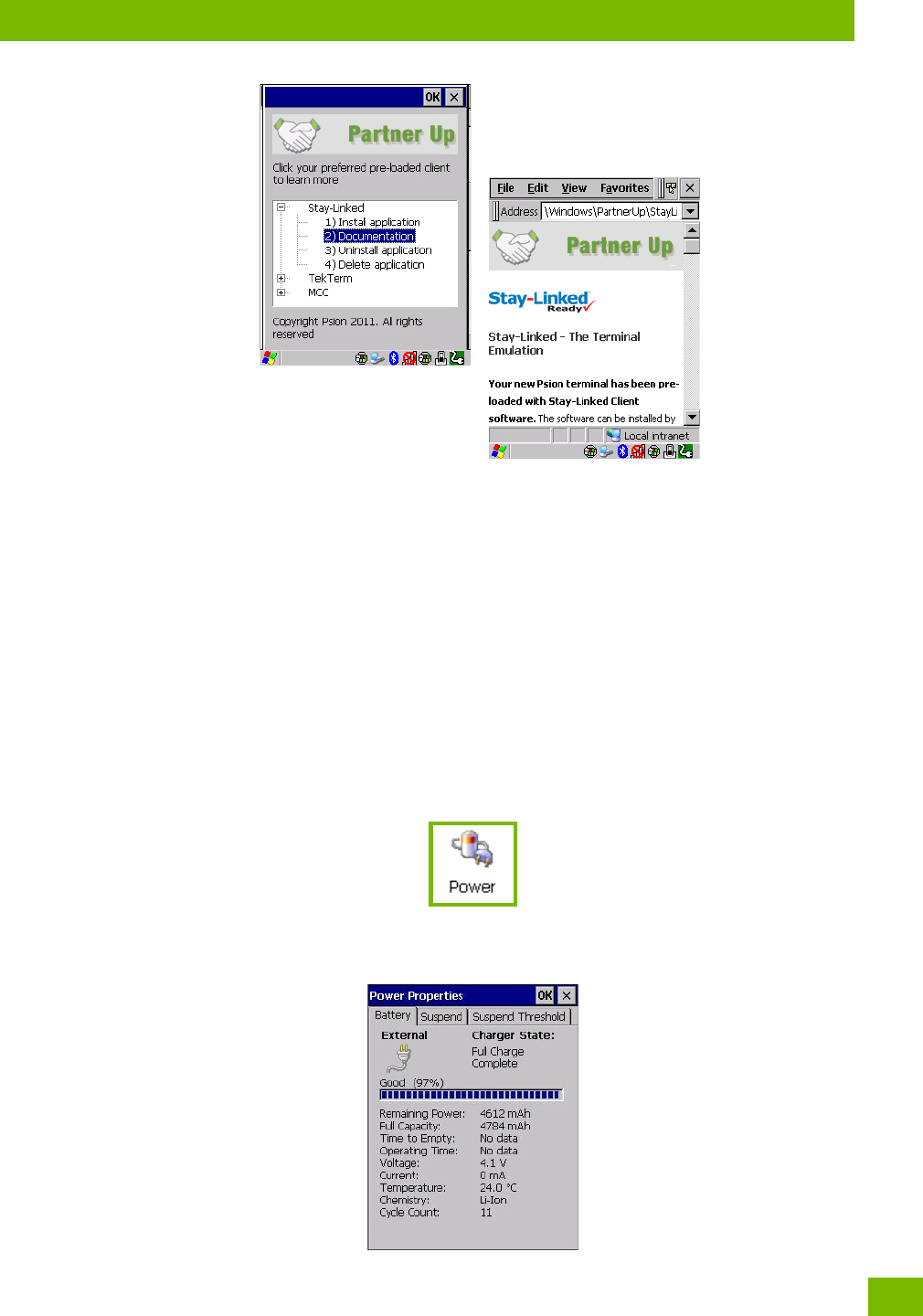
Chapter 4: Configuration
Pocket PC Compatibility
75
Psion 8516 Vehicle-Mount Computer User Manual
4.16 Pocket PC Compatibility
The 8516 supports the AYGShell API set that allows Pocket PC-compatible applications to run on the Vehi-
cle-Mount. Windows Embedded CE includes application programming interface (API) compatibility support
for the Microsoft Windows Powered Pocket PC 2002 shell in units running Windows Embedded CE.
The website listed below describes the APIs exposed through AYGShell and the application compatibility
between Windows Powered Pocket PC 2002-based applications and Windows Embedded CE based devices:
http://msdn.microsoft.com/library/default.asp?url=/li-
brary/en-us/dncenet/html/WINCENET_CEPCC_App.asp
4.17 Power Properties
This icon displays a Power Properties dialog box that indicates the unit’s battery capacity and allows you to
manage battery use.
•In the Control Panel, choose the Power icon.
4.17.1 Battery Capacity
•In the Power Properties dialog box, open the Battery tab to view battery details.
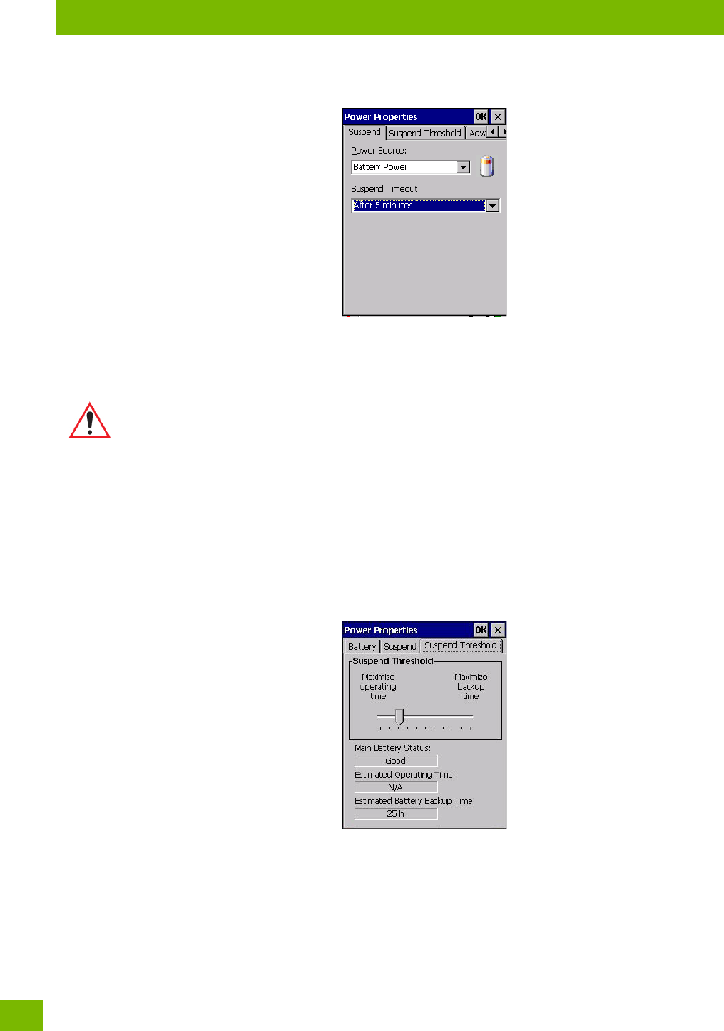
Chapter 4: Configuration
Power Saving Suspend
Psion 8516 Vehicle-Mount Computer User Manual
76
4.17.2 Power Saving Suspend
•In the Power Properties dialog box, open the Suspend tab.
Power Source
This drop-down menu allows you to specify whether the unit is using AC Power or Battery Power.
Suspend Timeout
When the 8516 is idle—not receiving any user input (a key touch, a scan, and so on) or system activity (serial
data, an activity initiated by an application, and so on)—the Vehicle-Mount uses the value assigned in the
Suspend Timeout field to determine when the unit will go to sleep (appear to be off).
When the time in the Suspend Timeout field elapses without any activity, the unit enters suspend state. In
suspend state, the 8516 CPU enters a sleep state, and wireless communication is shut off. The state of the
device (RAM contents) is preserved. Pressing [ENTER] wakes the system from suspend state.
4.17.3 Suspend Threshold and Estimated Battery Backup
The Suspend Threshold adjustment tells the system when to shut down when the battery drains. If you
choose Maximum Operating Time, the unit will run until the battery is completely empty; the RAM is only
backed up for a short period of time. If you choose Maximum Backup Time, the Vehicle-Mount shuts off with
more energy left in the battery so RAM can be backed up for a longer period of time.
Important: Psion recommends setting the Suspend value to 3 minutes. To further reduce
power consumption, carefully consider the duration of time that the display back-
light is ‘on’ (see “Backlight” on page 55).
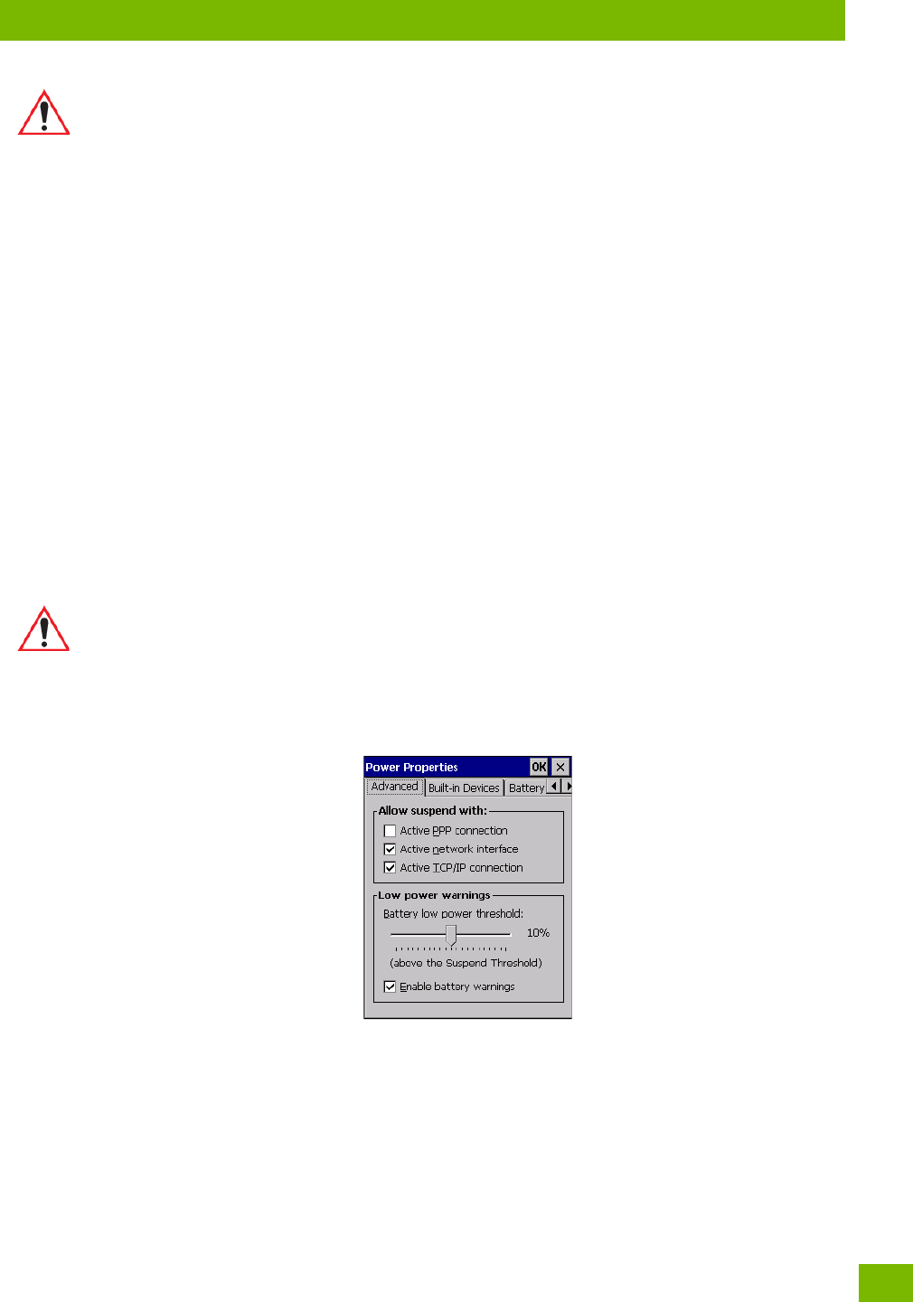
Chapter 4: Configuration
Advanced
77
Psion 8516 Vehicle-Mount Computer User Manual
The Estimated Battery Backup is the amount of battery power that has been reserved or set aside to
protect data until a charged battery can be installed in the Vehicle-Mount. When the battery capacity is de-
pleted up to the Estimated Battery Backup reserve specified in the Suspend Threshold menu, the 8516
shuts off automatically and uses the reserve power to preserve the data stored on the computer. Once the
8516 shuts down, it cannot be switched on until a fresh battery is installed.
• Slide the Suspend Threshold button to the right to increase the battery capacity reserved for backup
purposes. Data will be preserved to a maximum of 124 hours.
• Slide the Suspend Threshold button to the left to decrease the power reserved for backup purposes;
this increases the 8516 operating time—the amount of time the unit will operate before shutting
down—but reduces the power reserved for backup purposes to a minimum of 24 hours.
Internal super-capacitors will protect the data stored in the computer while the battery is swapped for a
fully charged one.
4.17.4 Advanced
•In the Power Properties dialog box, open the Advanced tab.
Allow Suspend With
This menu allows you to specify whether or not your unit will enter Suspend Mode while it is operating with
an active PPP connection, network interface or active TCP/IP connection.
Low Power Warnings
The sliding scale at the bottom of this menu allows you to specify the remaining battery capacity at which a
warning message is displayed on the 8516 screen, from 0% to 20%.
4.17.5 Built-in Devices
•In the Power Properties dialog box, open the Built-in Devices tab.
Important: Selecting Maximum backup time will reserve approximately 20% of the battery
capacity for memory backup. Once the battery is drained, the system RAM
memory is lost and the unit must cold boot.
In most real-time transaction environments this is not a problem (it only takes a
few seconds to cold boot). Batch transaction environments, where data is not
saved to a non-volatile memory (such as an SD FLASH card), may need to pay
particular attention to this parameter. Psion does not recommend the storage of
any valuable data in system RAM.
The 8516 Windows Embedded CE 6.0 environment does not store any critical data
in RAM (such as the registry or file system).
If your application does not save data to RAM, Psion recommends keeping the
Suspend Threshold setting as low as possible to maximize battery run time.
Important: Once the battery is removed, the super-capacitors will preserve the data stored on
the 8516 for approximately 4 minutes. It is critical that you install a charged
battery before this time elapses.
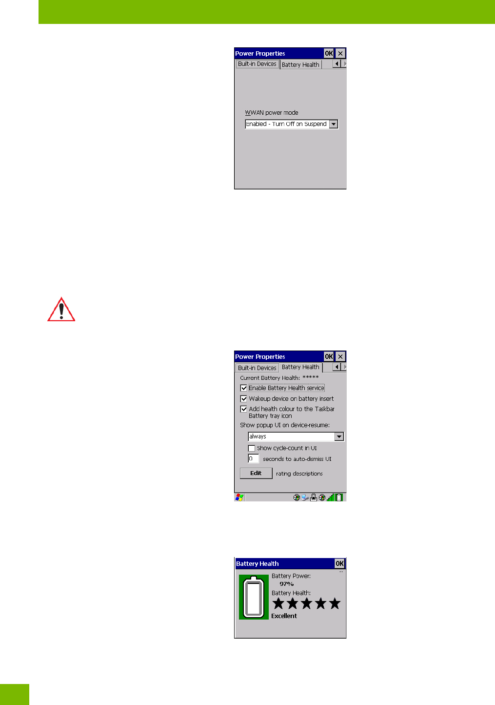
Chapter 4: Configuration
Battery Health
Psion 8516 Vehicle-Mount Computer User Manual
78
WWAN Power Mode
This menu allows you to enable power to your WWAN radio, and whether or not the radio will turn off when
the 8516 enters Suspend Mode. To configure the radio, please refer to Appendix E: “Wireless Wide Area
Network (WWAN) Settings”.
4.17.6 Battery Health
The Battery Health service provides an estimate of battery health based on a number of different measure-
ments, beyond just capacity.
•In the Power Properties dialog box, open the Battery Health tab.
Current Battery Health Meter
The Current Battery Health Meter default values are shown here as ***** (Excellent), *** (Used), and *
(Battery should be replaced). If you tap on the battery icon in the taskbar, a pop-up screen will show the
state of the battery. The image below shows the default Excellent status screen.
Important: Battery Health is an estimate and should not be depended on to provide a 100%
account of battery condition.
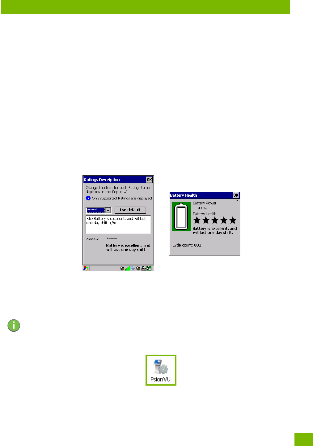
Chapter 4: Configuration
PsionVU Access
79
Psion 8516 Vehicle-Mount Computer User Manual
Enable Battery Health Service
This option allows you to enable the service. To access the menus after enabling the service, you will need
to either wait until a resume from Suspend or restart the 8516.
Wakeup Device on Battery Insert
When this option is enabled, whenever the battery is replaced the 8516 is powered up from Suspend and
the current health of the battery is displayed.
Add Health Colour to the Taskbar Battery Tray Icon
Enabling this option changes the background colour for the battery icon in the Taskbar, based on battery
condition: Green (excellent), Yellow (used), and Red (battery should be replaced).
Show Popup UI on Device-Resume
You can decide when the battery status pop-up user interface (UI) will appear, for how many seconds, and
whether the battery cycle count is displayed (off by default).
Edit – Changing Ratings Text
You can customize the ratings text with the Edit option. By enclosing your text within the html tag used for
Bold <b> (or removing the tag to unbold the text), you can change the text that will appear in the pop-up
battery status screen. For example, the default text “Excellent” can be changed to: “Battery is excellent,
and will last one day shift.”...
4.18 PsionVU Access
PsionVU Access enables you to customize your computer settings, remove or add shortcuts to the desktop
and Control Panel, and limit access to various different components on the computer and the system tray
icons for security.
•In the Control Panel, choose the PsionVU icon.
When opening the PsionVU application, the PsionVU Access dialog will come up that enables you to either
proceed to the PsionVU Settings menus, or change from you current Access mode to the other (Administra-
tor or User). The computer must be reset following a change, and a confirmation will appear to enable you
to continue or dismiss the change.
Note: The Desktop theme can be changed from the default Windows Classic Shell to the PsionVU
Shell either in the PsionVU Access settings (see “Other Shell Themes” on page 82) or by
tapping on the Desktop icon PsionVU Shell (see “The PsionVU Desktop Shell” on page 31).
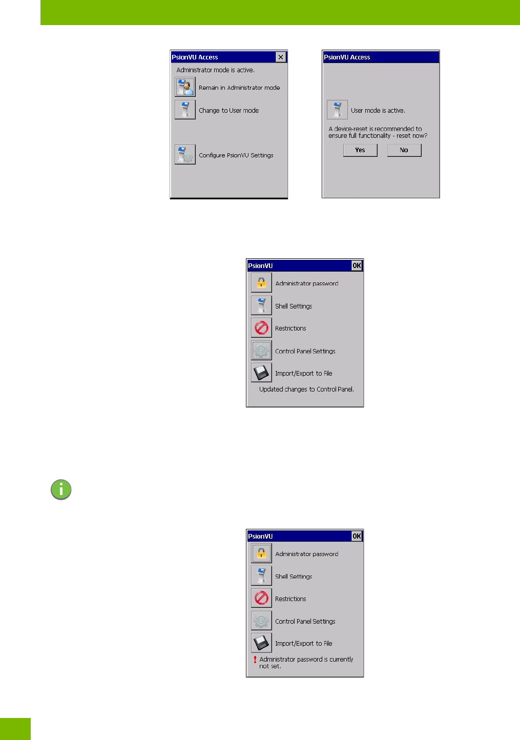
Chapter 4: Configuration
Administrator Password
Psion 8516 Vehicle-Mount Computer User Manual
80
When opening the PsionVu Settings option, the following menus will be available:
Figure 4.4 PsionVU Settings
4.18.1 Administrator Password
By setting an Administrator Password, you can limit access to various different components on the compu-
ter and the system tray icons for security. The default security setting allows User access to all options,
therefore restrictions and settings can be configured without setting a password.
When an administrator password is set, the restricted options are accessed using a key combination. If a
password has been set, the user would be prompted for the password.
Note: If a setting or restriction is configured without setting an Administrator password, the follow-
ing message is displayed: “!Administrator password is currently not set.” Once a password has
been set, the message will disappear.
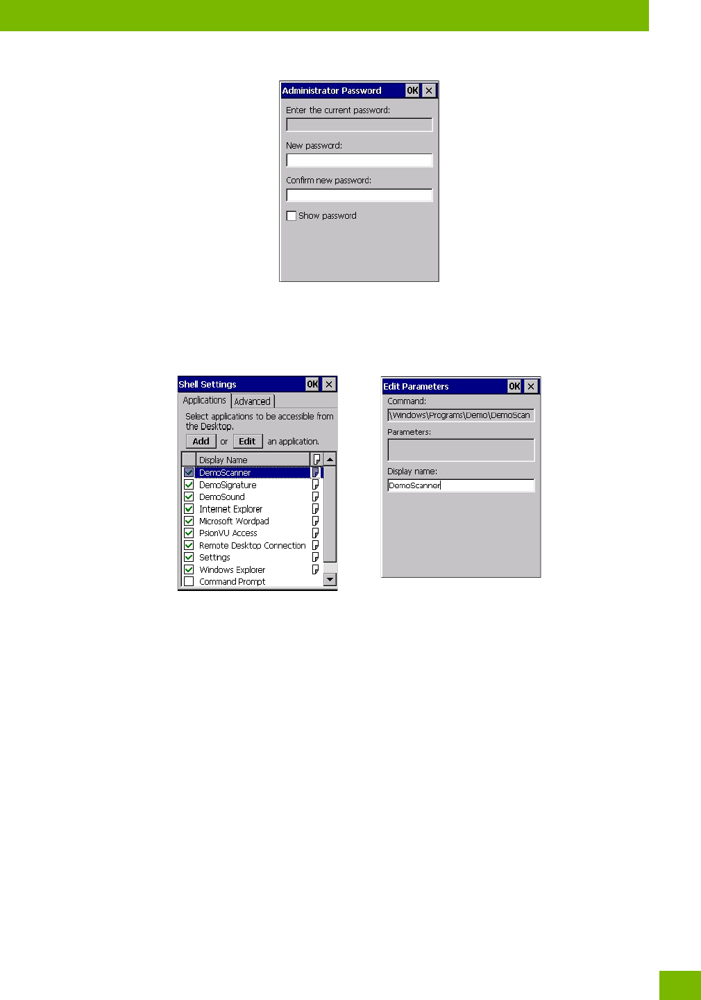
Chapter 4: Configuration
Shell Settings
81
Psion 8516 Vehicle-Mount Computer User Manual
The option Show Password changes the displayed password from hidden (***) to readable.
4.18.2 Shell Settings
The Shell Settings application has two menus: Applications and Advanced.
Applications
The Applications menu lists all the applications installed on the computer, alphabetically. The items checked
in this view are shown on the Desktop.
The Add and Edit buttons allow you to search for and add an application to the list of items in the selection
window. You can add a maximum of 18 applications, after which the Add option will be greyed out and the
following message is displayed: “!Maximum 18 entries reached.”
When you select an application and tap on Edit, you will see fields for Command, Parameters, and Display
Name.
•Command: The Command field is prefilled with the path and name of the executable (.exe) or corre-
sponding link (.lnk). If the selected file can’t be found (e.g. external memory card has been removed,
files have been deleted), a message will be displayed at the bottom of the screen: “These files
cannot be found.”
•Parameters: The Parameters option provides the option of adding era parameters to the application
(for .exe files only, not .lnk). For example, if the Command field is running “pword.exe” (Microsoft
WordPad), the Parameters field could specify a document to open.
•Display name: This is an editable field which is prefilled with the name of the application.
Advanced
The Applications menu allows you to enable or disable some device functions.
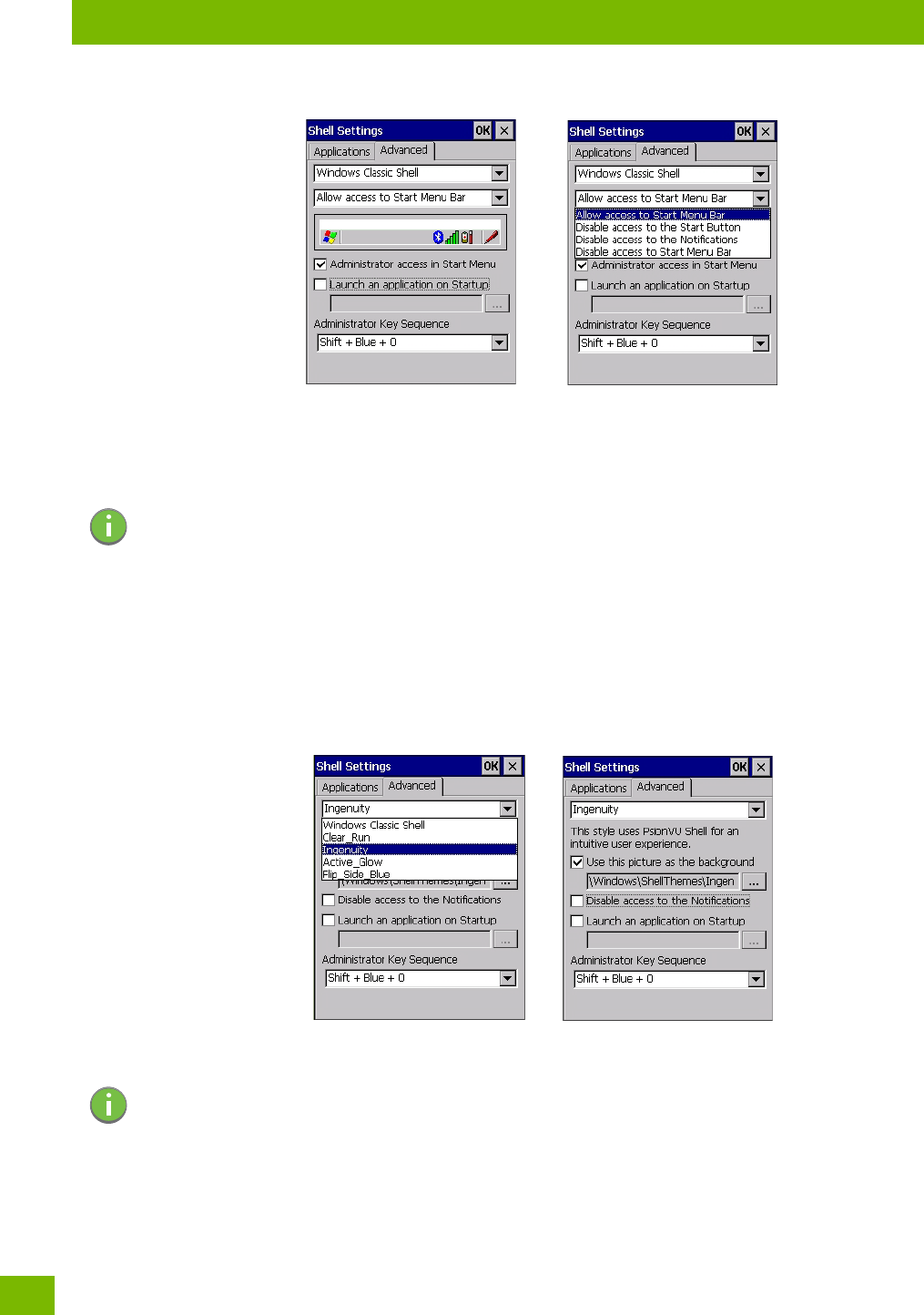
Chapter 4: Configuration
Shell Settings
Psion 8516 Vehicle-Mount Computer User Manual
82
Windows Classic Shell
The following options can be enabled or disabled in the Windows Classic Shell Desktop theme:
•Start Menu Bar: If disabled, access to both Start Menu and Notifications are disabled. The Notifica-
tion tooltips will still display. Any changes made will occur after a device reset.
•Start Button: If disabled, access to the Start Button and Notifications are disabled. The Notification
tooltips will still display.
•Notifications: If disabled, the Notifications tooltips will still display.
•Administrator Access in Start Menu: When this box is checked, the PsionVU Access program will
be shown in the Start Menu>Programs list.
The following item is not optional:
•Administrator Key Sequence: Sets the key sequence to open PsionVU Access.
Other Shell Themes
The following options can be enabled or disabled in the PsionVU Shell Desktop themes (shown in the
drop-down list as Windows Classic Shell, Clear_Run, Ingenuity, Active_Glow, and Flip_Side_Blue):
•Use this picture as the background: You can select a picture as the Desktop background.
•Notifications: If disabled, the Notifications tooltips will still display.
•Launch an application Startup: A window is displayed listing all of the installed and added applica-
tions. Any applications selected will startup after a reboot.
Note: If “Disable access to the Start Button” is selected, but the “PsionVU Access by Key Sequence”
remains unchecked, you will see the following status-message “!A Key Sequence is required
when the Start Button is disabled.”, the checkbox will be auto-checked, and the focus will be
set to the key-sequence selection.
Note: The Desktop theme can be changed from the default Windows Classic Shell to one of the
PsionVU themes shown here—but by tapping on the Desktop icon PsionVU Shell (see “The
PsionVU Desktop Shell” on page 31), the “Ingenuity” theme is automatically loaded. The com-
puter must be reset in order for the shell to change.
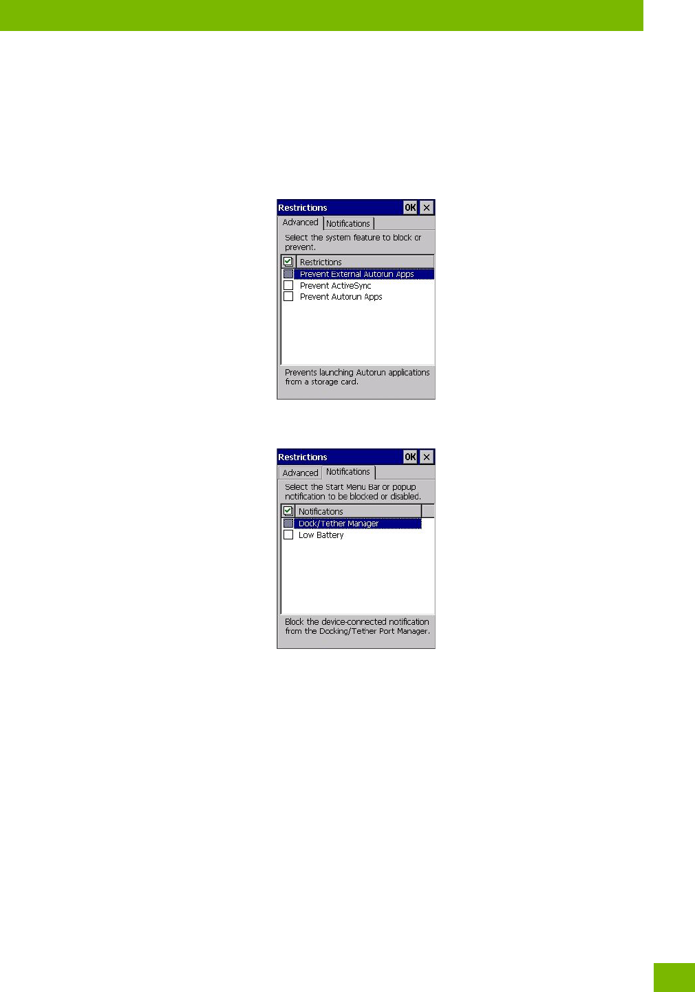
Chapter 4: Configuration
Restrictions
83
Psion 8516 Vehicle-Mount Computer User Manual
The following item is not optional:
•Administrator Key Sequence: Sets the key sequence to open PsionVU Access.
4.18.3 Restrictions
This section deals with items that are by default available to users but can be restricted by an administrator.
Advanced
The Advanced menu lists the system features you can restrict or block.
Notifications
The Notifications menu allows you to block or disable notifications.
4.18.4 Control Panel Settings
In these menus you can set which applets and tabs you want to Hide in Control Panel, and which applets
and tabs will be Accessible as a shortcut icon from the Desktop.
• You have the option of setting the entire applet or specific tabs within the applet as hidden or accessi-
ble. Any applet that can’t be set is greyed out.
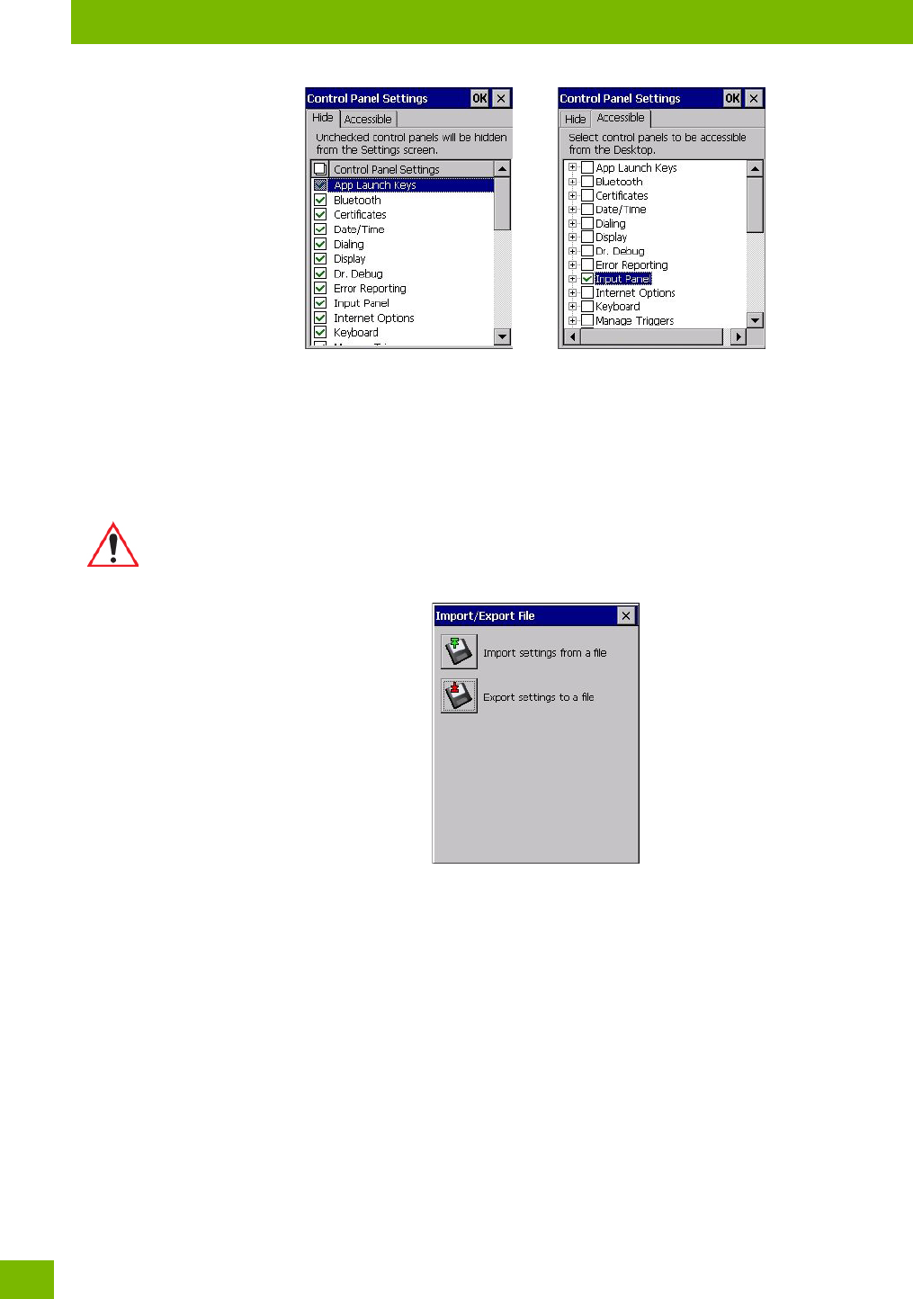
Chapter 4: Configuration
Import/Expo to File
Psion 8516 Vehicle-Mount Computer User Manual
84
• You can add a maximum of 18 applications, after which the following message is displayed: “!Maximum
18 entries reached.”
4.18.5 Import/Expo to File
This option enables you to Expo your settings file (.xml), and save it in the location of your choice. In addi-
tion, an Administrator has the option to import these settings from one device to multiple devices of the
same operating system.
Tapping on the Expo button will display a “Save As” Expo Settings dialog, with the default name
PsionVU_Settings.xml, which the Administrator can change even after it has been saved.
The .xml file contains all of the PsionVU configured settings, including the Administrator Password. When
the file is imported to a device, the new password is applied immediately.
• Whether choosing to import or expo files, the same file location options under My Device will be listed.
Following the action, a message stating the success of the operation and the location of the file will be
displayed.
• With the exception of the password, changes made to settings will take effect only after a warm reset.
If further changes to the configuration are made, they will overwrite the changes caused by the import
operation. After importing a file, a dialog will appear to enable you to reset now or later.
Important: A copy of this file should also be saved in a central repository for all Psion .xml
files with a predefined name so that other Psion utilities can locate it.
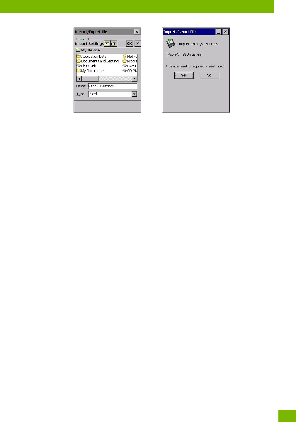
Chapter 4: Configuration
Remote Desktop Connection
85
Psion 8516 Vehicle-Mount Computer User Manual
4.19 Remote Desktop Connection
Remote Desktop Connection, located in Start>Programs, is an 8516 application used to connect to a
Windows Terminal Server so that you can run a “session” on the Server machine, using the 8516 (Windows
Embedded CE device).
Refer to the following website for step-by-step information about setting up this connection: http://www.mi-
crosoft.com/windowsxp/using/mobility/getstarted/remoteintro.mspx or contact Psion support services.
Locate the office closest to you at: www.psion.com/service-and-suppo.htm

Chapter 4: Configuration
Scanners
Psion 8516 Vehicle-Mount Computer User Manual
86
4.20 Scanners
The Scanners icon in the Control Panel provides dialog boxes in which you can tailor barcode options and
change the ports settings. If you wish to recover the factory defaults after making changes, the defaults
can be applied by holding the stylus on a parameter, which will pop up a menu allowing you to default that
parameter, or all settings. This option cannot be accessed without a touchscreen.
4.20.1 Barcodes
4.20.1.1 Scanner
The drop-down menu to the right of the Scanner option allows you to choose configurations for one of the
following scanner types, depending on what is installed in/on your Vehicle-Mount: Decoded (internal),
Decoded (Intermec ISCP), Imager and Non-decoded.
The symbologies listed in the Barcodes tab change to reflect the scanner you choose and the barcodes it
supports. Always defer to your barcode scanner’s programming manual when in doubt about the availabil-
ity or settings for any parameter.
Keep in mind that some barcode types are only available when an internal imaging scanner is installed. All
internal scanners can be configured using these dialog boxes.
4.20.1.2 Restoring Default Settings
If you want to restore the factory defaults after making changes, the defaults can be applied to a selected
parameter, sub-tree of parameters or all scanner parameters.
• Press and hold on a symbology (e.g., Code 128) to display a pop-up menu.
Note: Your 8516 comes preconfigured from the factory for internal scanner types. The type of
scanner installed can be determined from the System icon in the Control Panel, under the
System Properties tab.
Important: To improve the decode speed and performance, enable (set to ‘on’) only those
codes that are required by the application.
For information on configuring the barcode symbologies, see Appendix D: “Scan-
ner Settings”.
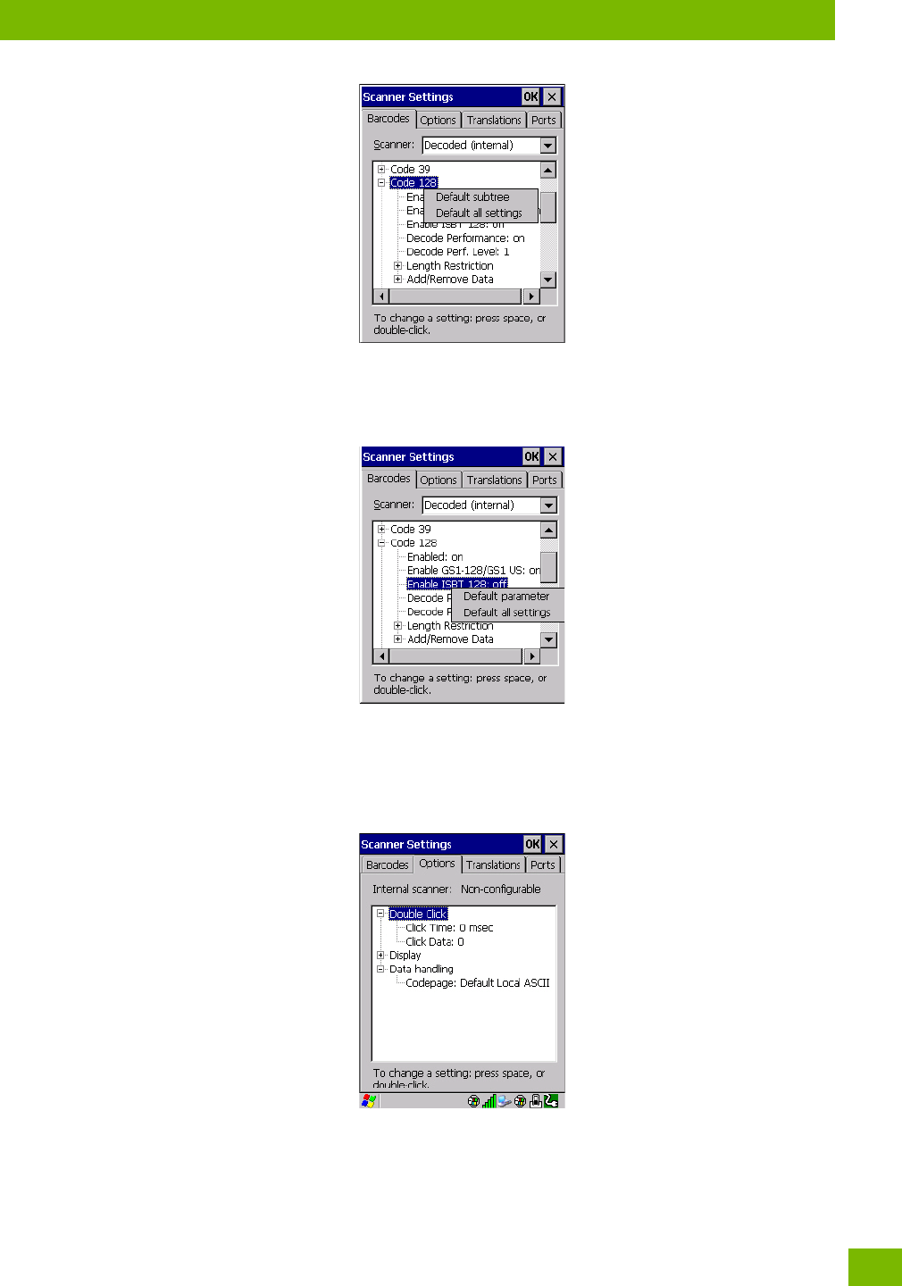
Chapter 4: Configuration
Options
87
Psion 8516 Vehicle-Mount Computer User Manual
•Choose Default subtree to reset only the parameters in the symbology you selected, or choose
Default all settings to reset all scanner parameters to default settings.
To reset a single parameter to its default setting:
• Press and hold on the parameter you want to reset.
•Choose Default parameter to reset the parameter to the default setting.
4.20.2 Options
This tab allows you to tailor the double-click parameters, display, and data handling options associated with
your scanner.

Chapter 4: Configuration
Options
Psion 8516 Vehicle-Mount Computer User Manual
88
4.20.2.1 Double Click Parameters
Click Time (msec)
This parameter controls the maximum gap time (in milliseconds) for a double-click. If the time between the
first and second clicks of the scanner trigger is within this time, it is considered a double-click. The allowa-
ble range is 0 to 1000. A value of zero disables this feature.
A double-click produces different results depending on whether or not a value is assigned in the “Click
Data” parameter. When a value is not assigned for the “Click Data”, double-clicking the scanner trigger
overrides the target dot delay set in the “Dot Time” parameter and initiates a normal scan sweep. If a value
is assigned for the “Click Data” parameter, double-clicking the scanner trigger inserts the “Click Data”
value rather than initiating a scan.
Click Data
This parameter determines which character is sent to the application installed in your 8516 following a dou-
ble-click. A dialog box appears, asking that you press the key you want to insert. The ASCII/Unicode key
value of the keypress is displayed.
Pressing the [ESC] key in this dialog box resets the data to zero.
4.20.2.2 Display Parameters
Scan Result
When this parameter is enabled, the type of barcode and the result of the scan appear on the screen. Note
that this information is only displayed after a successful decode and is visible only while the scanner trigger
is pressed. When the trigger is released, this information is cleared from the screen.
Scan Indicator
When this parameter is enabled, the laser warning logo appears on the display whenever the scanner is ac-
tivated.
Scan Result Time (sec)
The value assigned to the Scan Result Time parameter determines how long the scan results of a successful
scan are displayed on the screen. Time is measured in seconds, and a value of 0 (zero) disables the param-
eter. When you choose this option, a dialog box appears where you can enter a value.
Good Scan Beep and Bad Scan Beep
These parameters determine whether or not the 8516 emits an audible scanner ‘beep’ when a good (suc-
cessful) scan or a bad (unsuccessful) scan is performed. Set these parameters to either on to enable the
beeper or off to disable it.
Multiple Beep Tones
You can set the audible scanner ‘beep’ to emit a series of three beeps instead of one. Set this parameter to
on to enable the multiple beep tones.
Soft Scan Timeout
This parameter is used by the SDK “Scan” function (soft-scan: starting a scan session via the SDK function,
instead of a physical user trigger press). The value assigned to this parameter determines the soft-scan
timeout from 1 to 10 sec (default is 3 sec).
Scan Log File
If this parameter is enabled, the input barcode and the modified/translated output barcode are logged in
the file \Flash Disk\ScanLog.t. Keep in mind that if Scan Log File is enabled, there is a slight performance re-
duction when performing multiple scans since the log file is written to persistent storage.
Note: To remove the scan result from the screen before the “Result Time” has expired, point the
scanner away from the barcode and press the trigger.
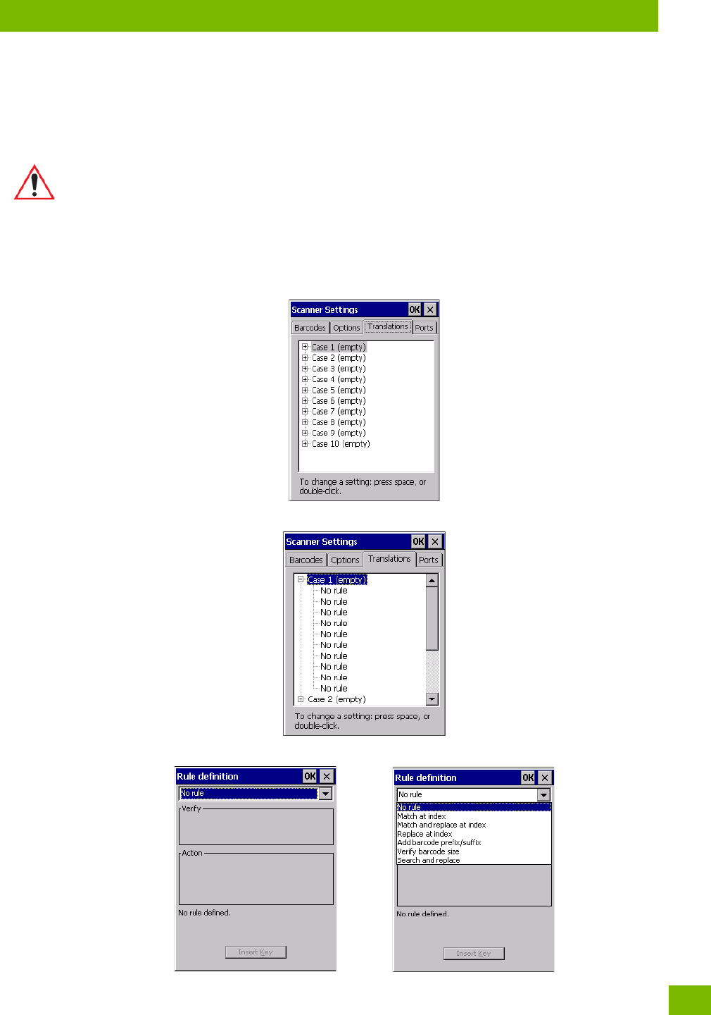
Chapter 4: Configuration
Translations
89
Psion 8516 Vehicle-Mount Computer User Manual
4.20.2.3 Data Handling
Codepage
If you are encountering a scan failure because there is an unrecognized language character in the barcode,
the Codepage option may correct the problem by allowing the ISO-8859-1 Latin 1 codepage to be used. The
default value is Default Local ASCII.
4.20.3 Translations
The Translations menu allows you to define up to 10 cases, each consisting of up to 10 rules in sequential
order. Only one case will be applied to a barcode and a case will only be applied if all rules specified in the
case are successful—if a rule within a case fails, the entire case fails.
•In the Translation menu, tap on the Case # to create rules.
•Tap on the No rule drop-down menu to display the rules.
Important: Do not change this parameter from the default setting unless you are certain that
it will correct your scan problem.