Psion PX750BT Psion Teklogix Handheld Computer User Manual Ik n Rugged PDA Phone
Psion Inc Psion Teklogix Handheld Computer Ik n Rugged PDA Phone
UserManual.wiki
>
Psion
>
PX750BT User Manual
User Manual
Navigation menu
Upload a User Manual
Namespaces
Wiki Guide
HTML
PDF
Info
Views
User Manual
Discussion / Help
Navigation


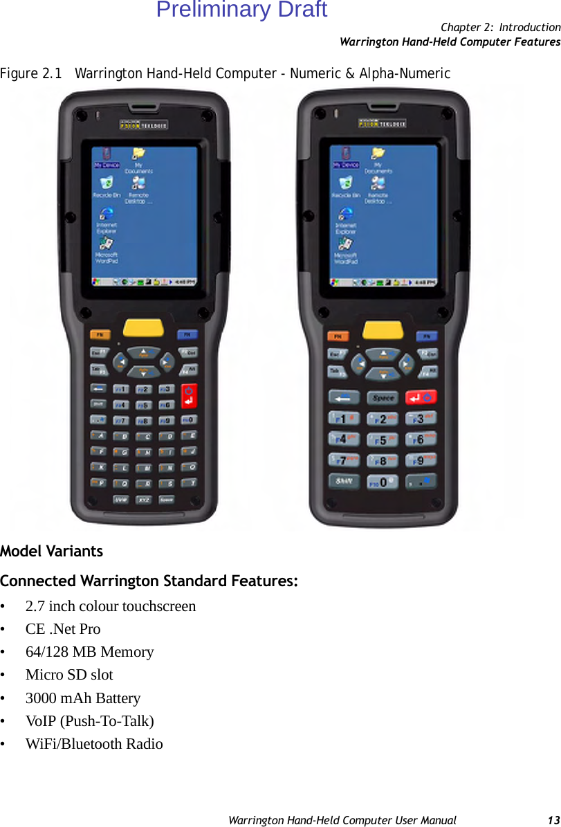
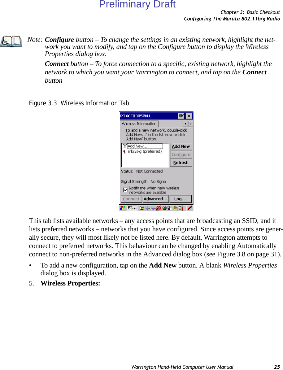
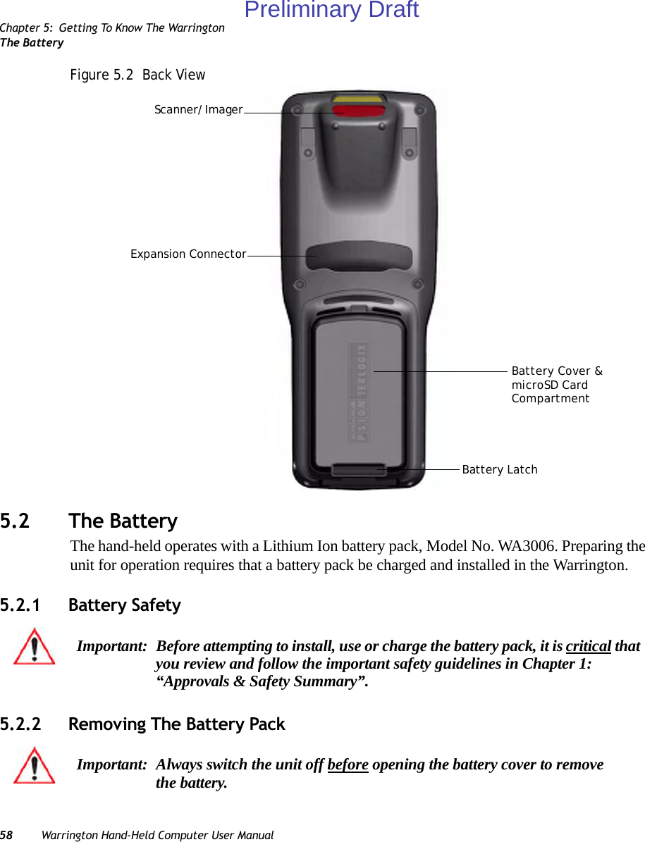
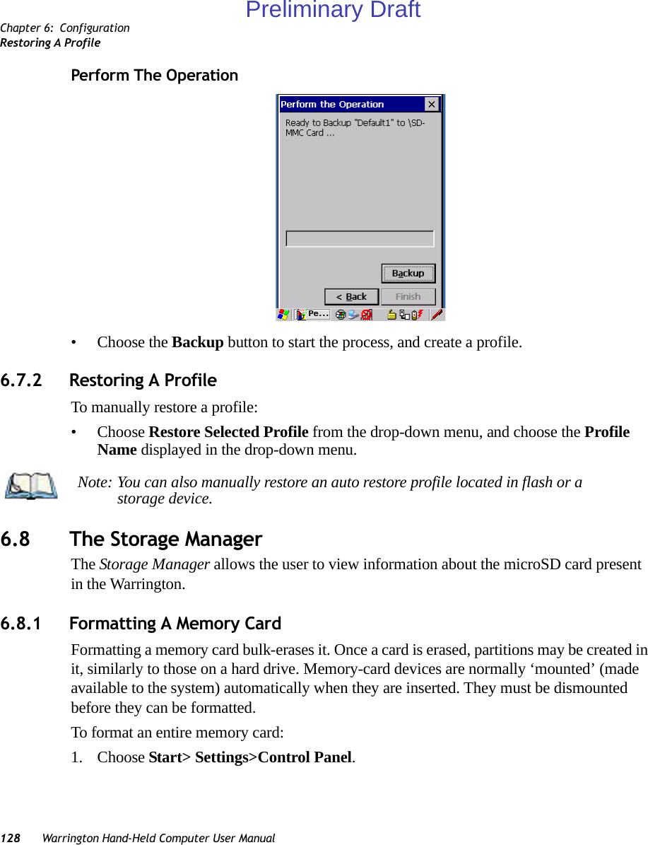
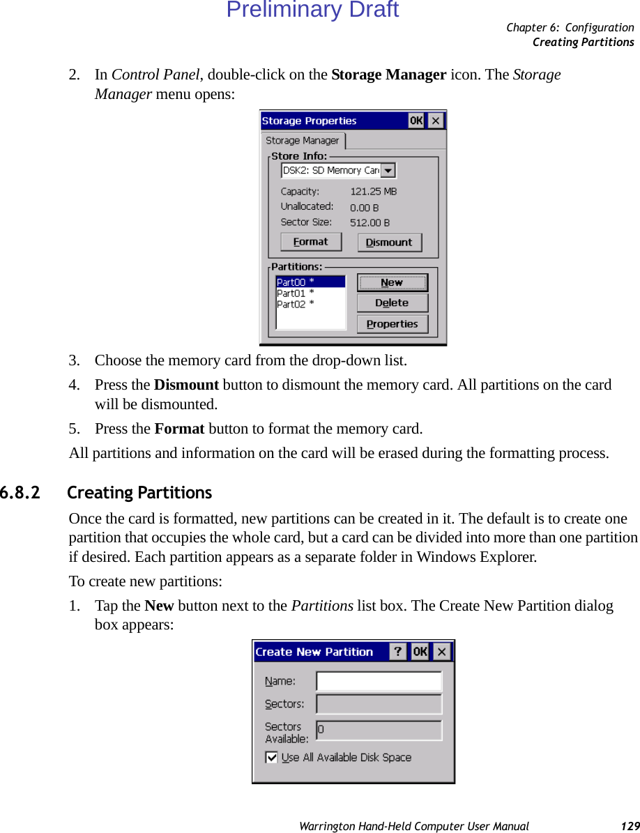
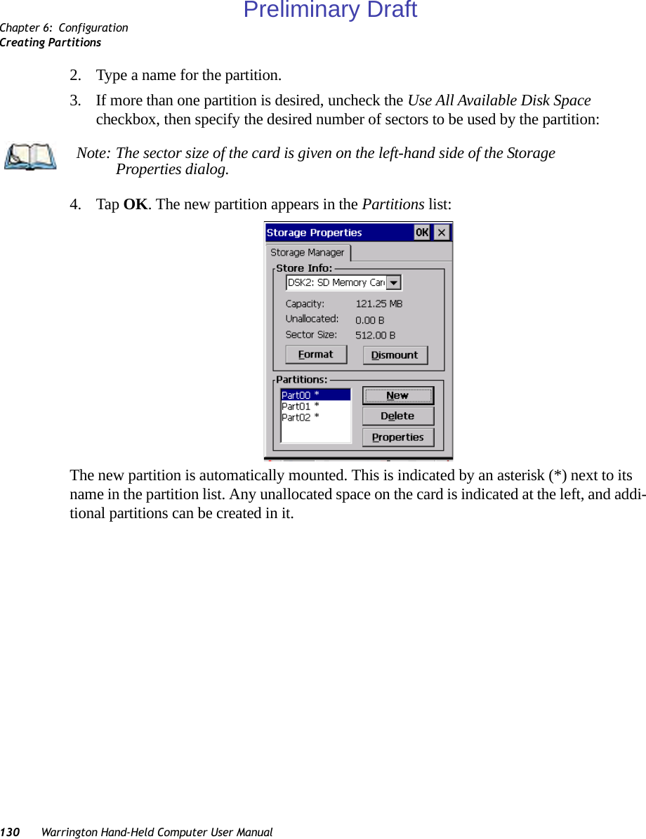
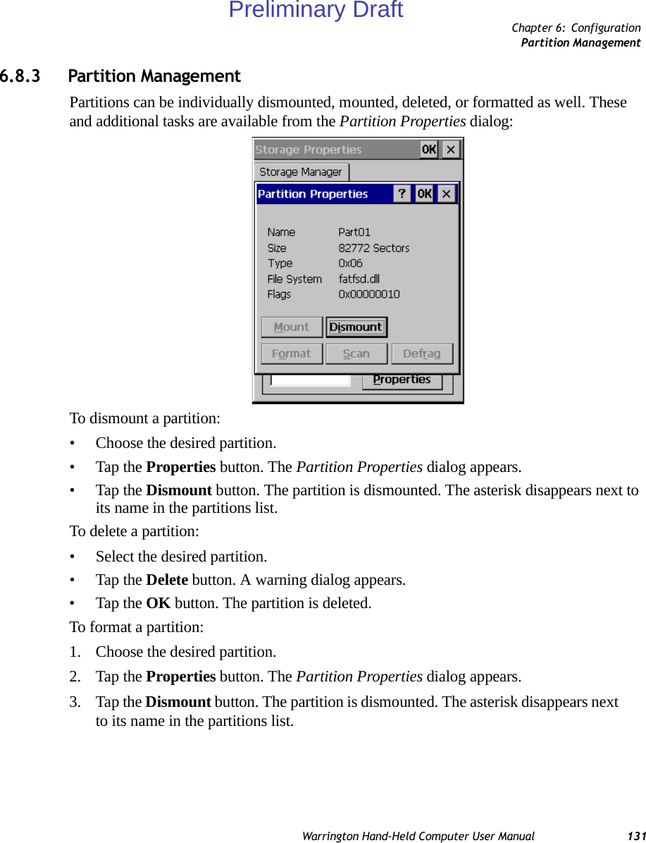
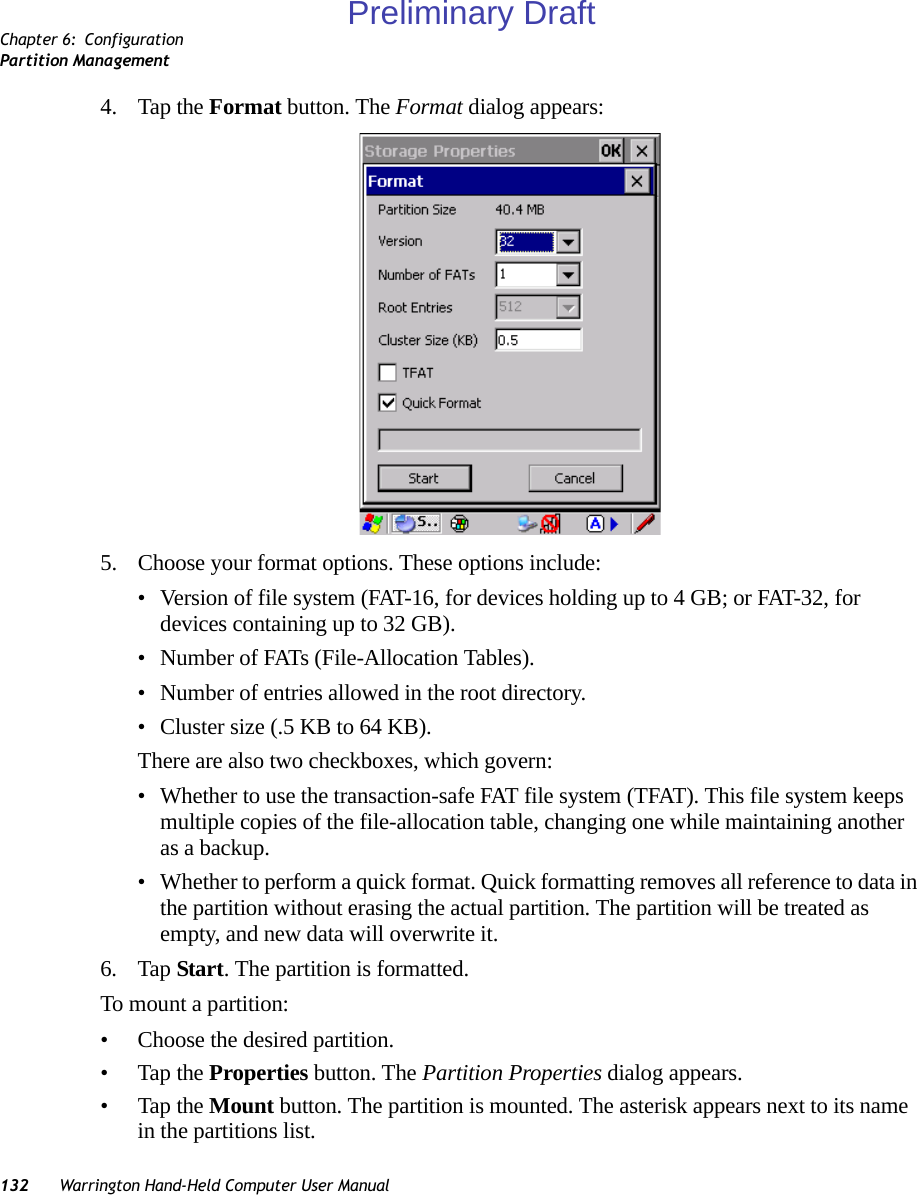
![Chapter 3: Basic CheckoutPreparing The Warrington Hand-Held For OperationWarrington Hand-Held Computer User Manual 213.1 Preparing The Warrington Hand-Held For Operation3.1.1 The BatteryThe Warrington is powered with a 3000 mAh Lithium Ion battery pack – Model No. WA3006.3.1.1.1 Charging The Main BatteryBattery packs shipped from the factory are charged to approximately 40% and must be fully charged prior to use. Batteries can be charged using a variety of chargers and docking sta-tions along with a Warrington internal charger. When using the internal charger, a suitable power source is required. All chargers and docking stations are described in Chapter 7: “Pe-ripheral Devices & Accessories” beginning on page 184.3.1.2 The Super CapacitorAn onboard super capacitor provides up to 10 minutes of suspend mode backup power to the Warrington to give you time to swap in a new battery; all unnecessary draws on power such as the display and CPU are shut down to preserve power. If the battery pack reaches its Suspend Threshold (refer to “Suspend Threshold” on page 102) and the hand-held shuts down, the super capacitor will protect the data stored in the unit until a charged battery pack is installed.Warning: Before charging the battery, it is critical that you review the battery safety guidelines in Chapter 1: “Approvals & Safety Summary”. Important: Before opening the battery cover on your Warrington, press [FN/BLUE] [ENTER] to turn off the hand-held. Removing the battery while the unit is running may cause the hand-held to reboot.Note: If you are powering up a new unit, a warning message may appear on the screen indicating that the backup battery capacity is low. To recharge the internal battery, you must fully charge the Warrington with the main battery installed in the unit.Important: When you initially power up the hand-held, leave the battery in the unit for a minimum of 2 minutes to allow the super capacitor to reach full capacity.Preliminary Draft](https://usermanual.wiki/Psion/PX750BT/User-Guide-963956-Page-33.png)
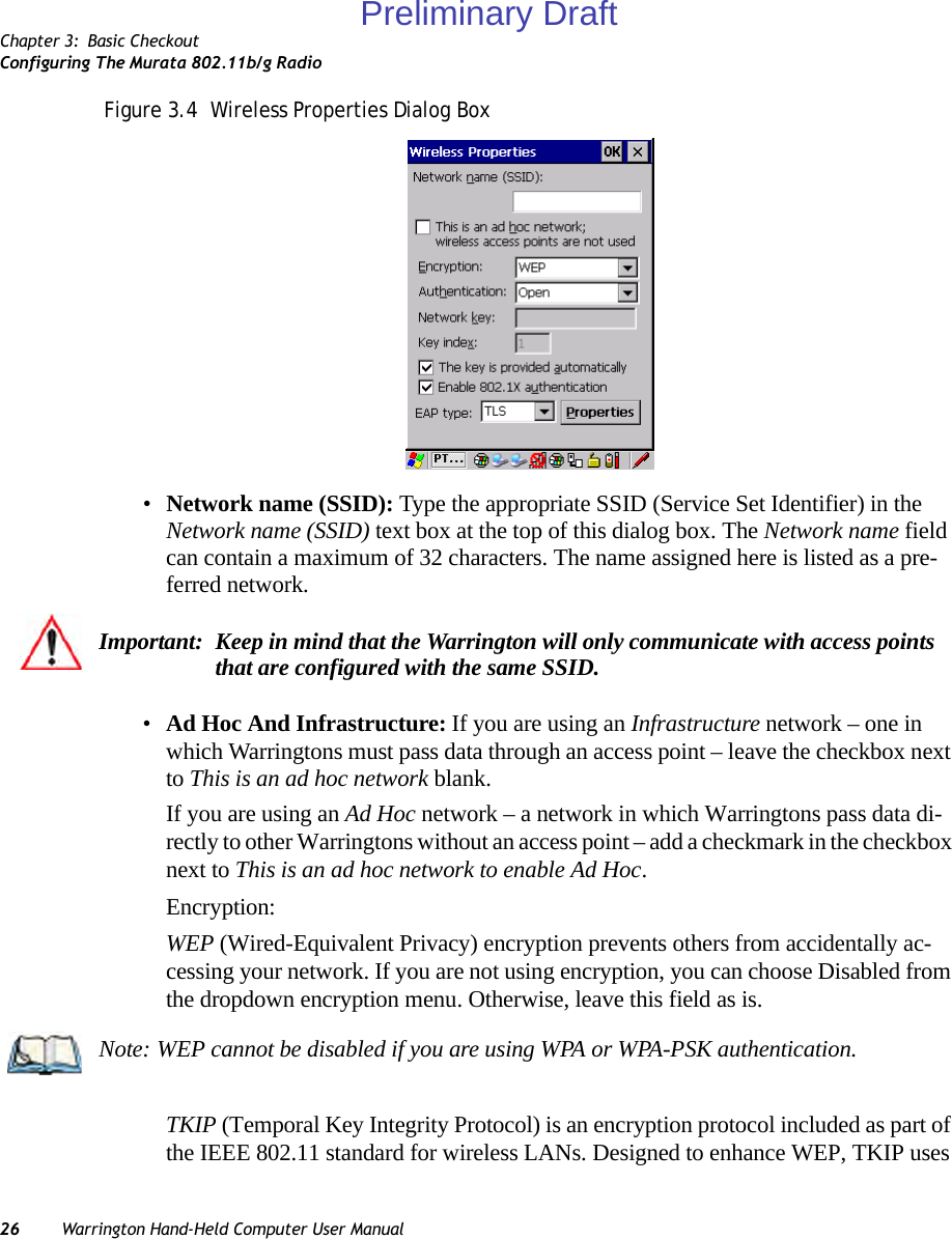
![Chapter 3: Basic CheckoutSwitching The Warrington On And Off22 Warrington Hand-Held Computer User Manual3.2 Switching The Warrington On And Off3.2.1 Installing The Battery And Switching The Unit On• Push the release button at the base of the battery cover to unlatch it. Remove the battery cover.•Insert a charged battery into the unit, making certain that the connectors on the battery are aligned with those in the Warrington battery well. • Replace the battery cover.To switch the Warrington on:• Press and hold down the [ENTER] key for at least one second.• When the LED flashes green, release the [ENTER] button.The desktop screen is displayed.3.2.2 Switching The Unit Off (Suspend)• Press the [FN/BLUE] key, and then press [ENTER].3.3 Calibrating The TouchscreenThe Warrington touchscreen is factory-calibrated and ready-to-go; however, over time the touchscreen operating parameters may change, and may need to be recalibrated for correct operation. Refer to “Calibrating The Touchscreen” on page 65 for details.Important: Press [FN/BLUE] [ENTER] to turn off the hand-held before removing battery on your Warrington. If the battery is removed while the unit is still powered on, the unit may reboot.Note: If you are using a docking station or an external power supply, you can insert an uncharged battery and switch it on.Note: If the unit was already in use—the unit may be off (suspend state) – pressing [ENTER] ‘wakes’ the unit from this state. The screen in which you were working prior to the suspend state is displayed.Note: Keep in mind that the touchscreen function can be turned off (see “Touch” on page 105).Preliminary Draft](https://usermanual.wiki/Psion/PX750BT/User-Guide-963956-Page-34.png)
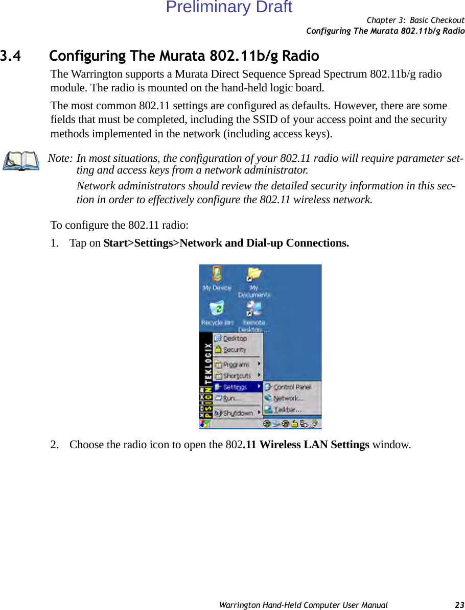
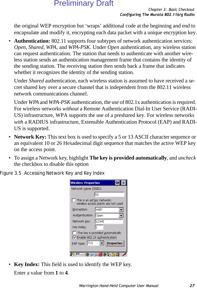
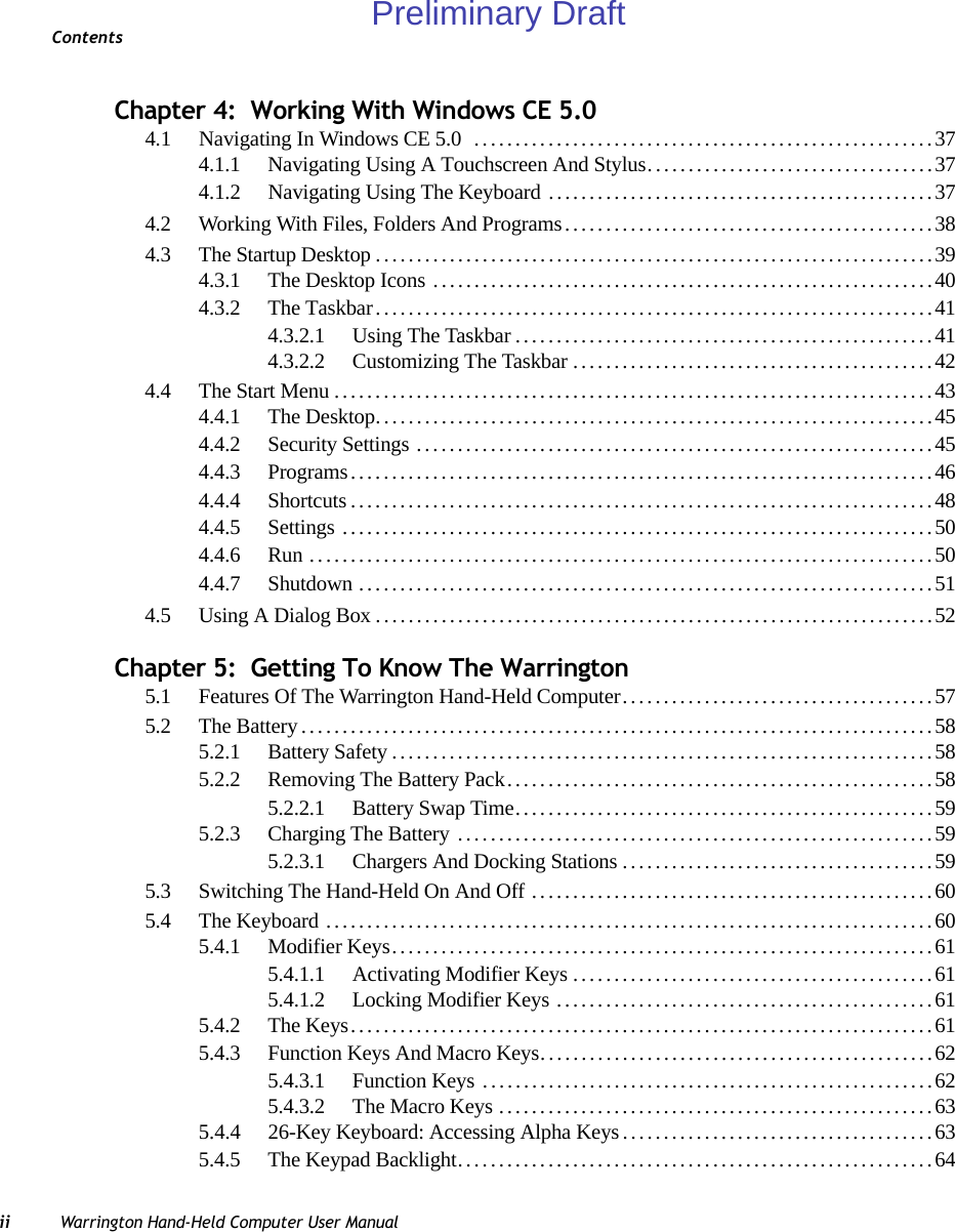
![Chapter 3: Basic CheckoutAssigning An IP Address28 Warrington Hand-Held Computer User Manual•Enable 802.1x authentication: 802.1X is the IEEE standard that offers additional security for local area networks. It provides authentication for user devices attached to an Ethernet network, whether wired or wireless. A security protocol packet such as TLS or MD5 encapsulated in an EAP is used in conjunction with the 802.1X standard to authenticate users at the MAC layer. Available EAPs are listed in the dropdown menu next to the EAP option.To activate 802.1X, highlight 802.1x authentication, and check the checkbox.•EAP Type (Extensible Authentication Protocol): This dropdown menu lists the EAP types available on your system. The items in this dropdown menu will vary depending on your network setup. Keep in mind also that some authentication proto-cols require that you select a Certificate. By selecting the Properties button, you will be able to select a Certificate. “Certificate Assignment” on page 109 provides a website that outlines how to create certificates for your network.6. Saving and exiting the radio setup.Once you’ve completed the configuration, press [ENTER], or tap on OK.The connection you created will be listed in the Wireless Information tab as a preferred network. The radio will search for the SSID and will compare the WEP and authentica-tion information you specified. If there is a match between your hand-held settings and the access point settings, the hand-held will communicate on the network through the access point.3.4.1 Assigning An IP AddressIf your network is not using a DHCP server, you will need to assign an IP address.• Tap on the IP Information tab.Preliminary Draft](https://usermanual.wiki/Psion/PX750BT/User-Guide-963956-Page-40.png)
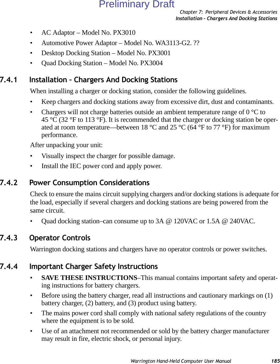
![Chapter 3: Basic CheckoutAssigning An IP AddressWarrington Hand-Held Computer User Manual 29Figure 3.6 IP InformationTo define a static IP address:• Tap on the Configure button.• Tap the stylus on the radio button next to Specify an IP address to select it.• Type an IP, Subnet Mask and Default Gateway address in the appropriate fields. Press [ENTER] to save your information.Note: Tapping the Renew button forces the Warrington to renew or find a new IP address. This is useful if, for example, you are out of communication range for a longer period of time and your hand-held is dropped from the network.Preliminary Draft](https://usermanual.wiki/Psion/PX750BT/User-Guide-963956-Page-41.png)
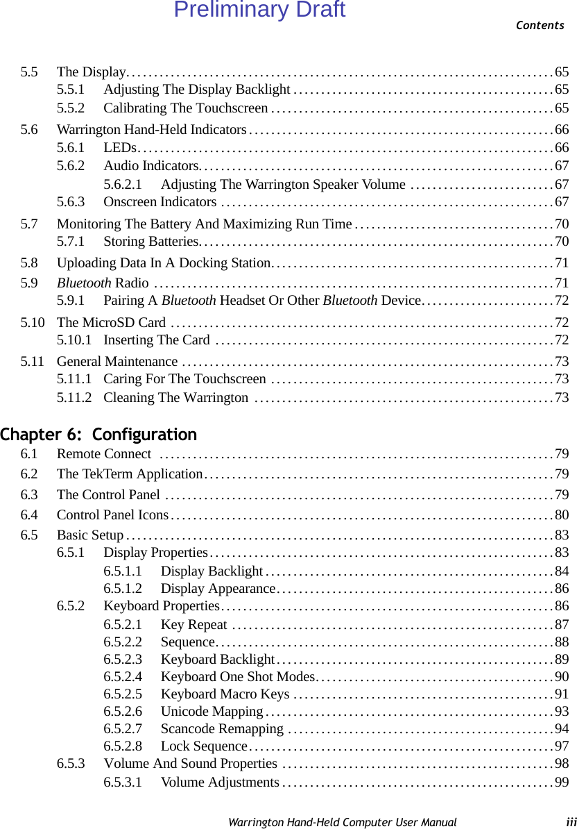
![Chapter 3: Basic CheckoutRearranging Preferred NetworksWarrington Hand-Held Computer User Manual 31Figure 3.8 Advanced Settings3.4.3.1 Rearranging Preferred NetworksThe Warrington attempts to connect with the networks listed in this dialog box in sequence, beginning at the top of the list. If you need to rearrange this list of networks – move net-works up and down in the list:• Tap in the Networks List, and highlight the network that you want to move up or down in the list.• To move the highlighted item in the list upward or downward, tap on the Up or Down button.3.4.3.2 Deleting A Preferred NetworkTo delete a network from this list:•In the networks list, highlight the network that you want to remove.• Tap on the Delete button.3.4.3.3 Changing Network PropertiesTo change the properties of an existing preferred network:• Highlight the network that you want to modify.• Tap on the Properties button.• Make any necessary changes in the Wireless Properties dialog box, and press [ENTER] to save the changes.Preliminary Draft](https://usermanual.wiki/Psion/PX750BT/User-Guide-963956-Page-43.png)
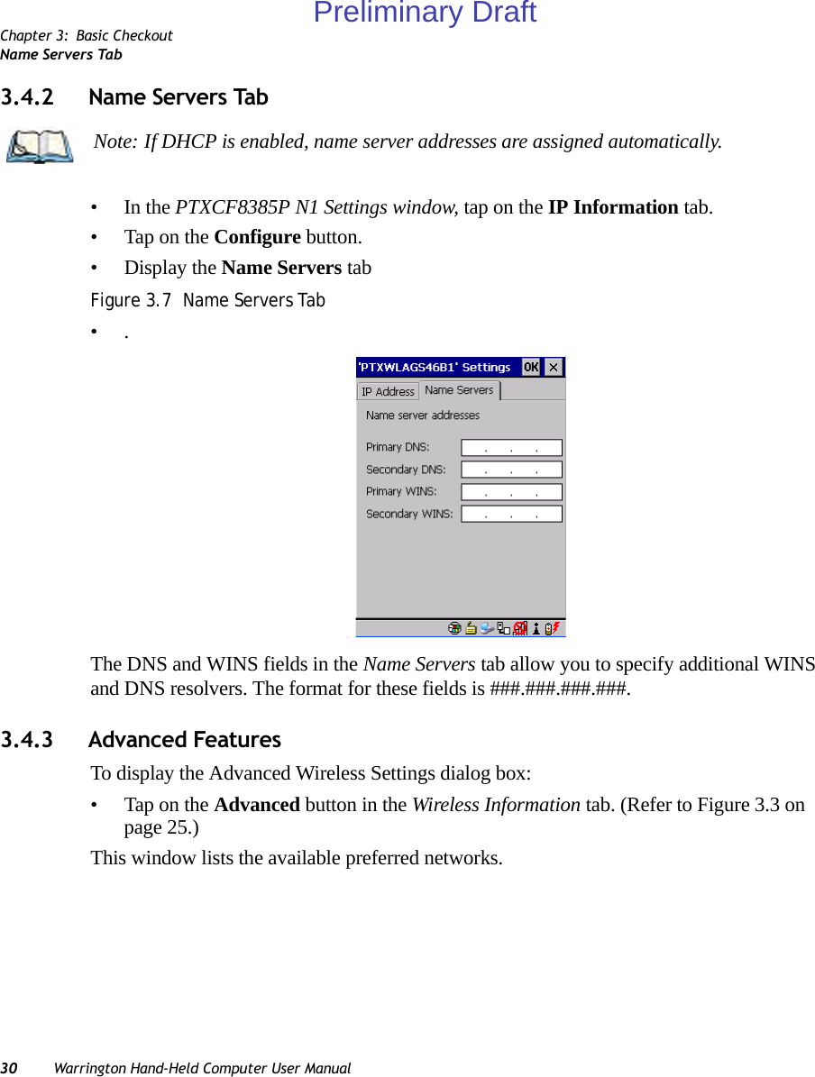
![Chapter 3: Basic CheckoutVoIP – Using Push-To-TalkWarrington Hand-Held Computer User Manual 333.7 VoIP – Using Push-To-Talk•••3.8 Resetting The Warrington3.8.1 Performing A Warm ResetTo execute a warm reset:• Press and hold down the [FN/BLUE] key and the [ENTER] key simultaneously for a minimum of six seconds.A warm reset closes open applications; any unsaved data are lost. Installed programs and saved data are preserved. 3.8.2 Performing A Cold ResetTo perform a cold reset and launch the Windows 5.0 operating system (bypassing the BooSt menu):• Press and hold down the [FN/BLUE] [FN/ORANGE] and [ENTER] keys simultane-ously for a minimum of six seconds.Note: You do not need to reset your Warrington after configuring the radio.Preliminary Draft](https://usermanual.wiki/Psion/PX750BT/User-Guide-963956-Page-45.png)

![Chapter 4: Working With Windows CE 5.0Navigating In Windows CE 5.0Warrington Hand-Held Computer User Manual 374.1 Navigating In Windows CE 5.0 Graphic user interfaces like Windows CE 5.0 for portable devices and desktop Windows (2000, XP, etc.) utilize ‘point and click’ navigation. An equivalent keyboard shortcut is also available for every ‘point and click’ action.Windows CE 5.0 supports the same ‘point and click’ user interface and keyboard shortcuts as desktop Windows with one difference—the ‘point and click’ action is accomplished using a touchscreen rather than a mouse. Actions can be performed using any combination of keyboard shortcuts or touchscreen tapping. 4.1.1 Navigating Using A Touchscreen And StylusEach Warrington is equipped with a stylus—a pointing tool that looks like a pen—stored in a slot at the top of the unit. The stylus is used to select objects on the touchscreen.To choose an icon, open a file, launch an applet, or open a folder:• Double-tap the stylus on the appropriate icon.4.1.2 Navigating Using The KeyboardIf your Warrington touchscreen has been disabled, you can use the keyboard to choose icons, navigate dialog boxes, display the desktop, and so on. If your unit has already been fully configured and your application is launched at startup, you’ll have little need for key-board navigation, but you can refer to Table 4.1 for a description of the navigation keys.Note: In order to access many of the menus discussed in this chapter, the security level must be set to ‘Supervisor’ (see “Security Settings” on page 45).Note: If the touchscreen is not registering your screen taps accurately, the touchscreen may need recalibration. Refer to “Calibrating The Touchscreen” on page 65.Note: To prevent damage to the touchscreen, use only the stylus (pen) supplied with your Warrington.Table 4.1 Keyboard NavigationOperation Key or Key CombinationSwitch between active applications [ALT] [TAB]Open task manager [ALT] [ESC]Preliminary Draft](https://usermanual.wiki/Psion/PX750BT/User-Guide-963956-Page-49.png)
![Chapter 4: Working With Windows CE 5.0Working With Files, Folders And Programs38 Warrington Hand-Held Computer User ManualKeep in mind that unlike a desktop computer, the Warrington does not support key chording (pressing two keys at the same time). You must press one key followed by the next in se-quence. Refer to Section 4.2: “Working With Files, Folders And Programs” for additional details about keyboard navigation.4.2 Working With Files, Folders And ProgramsFigure 4.1 Working With Windows IconsMove the cursor Arrow keysOpen file, folder or icon [ENTER]Exit & Save [ENTER]Close/Exit & Do Not Save [ESC]Navigate Dialog Boxes [TAB]To move cursor up: [SHIFT] [TAB]To display the contents of the next ‘tab’ in a dialog box: [CTRL] [TAB]Select Radio Button/Press Button [SPACE]Go to Start Menu [FN/BLUE][0]Table 4.1 Keyboard NavigationOperation Key or Key CombinationFolderFileProgram IconPreliminary Draft](https://usermanual.wiki/Psion/PX750BT/User-Guide-963956-Page-50.png)
![Chapter 4: Working With Windows CE 5.0The Startup DesktopWarrington Hand-Held Computer User Manual 39• Double-tap on the appropriate icon—either a folder icon, a program icon or a file icon—to open or launch your selection.If you’re using the keyboard:• Use the arrow keys to highlight the icon you want to open or launch.• Press [ENTER].4.3 The Startup DesktopWhen the Warrington boots up, the startup desktop (shell) is displayed. Any applications stored in the Startup folder start up immediately.Figure 4.2 The Warrington Startup DesktopTo access desktop icons:• Double-tap on the icon to open a window or, in the case of an application icon, launch an application.On the keyboard:• Use the arrow keys to highlight the icon, and press [ENTER] to launch the highlighted icon.Note: The startup folder is located in \Windows\StartUp and \Flash Disk\StartUp.Preliminary Draft](https://usermanual.wiki/Psion/PX750BT/User-Guide-963956-Page-51.png)
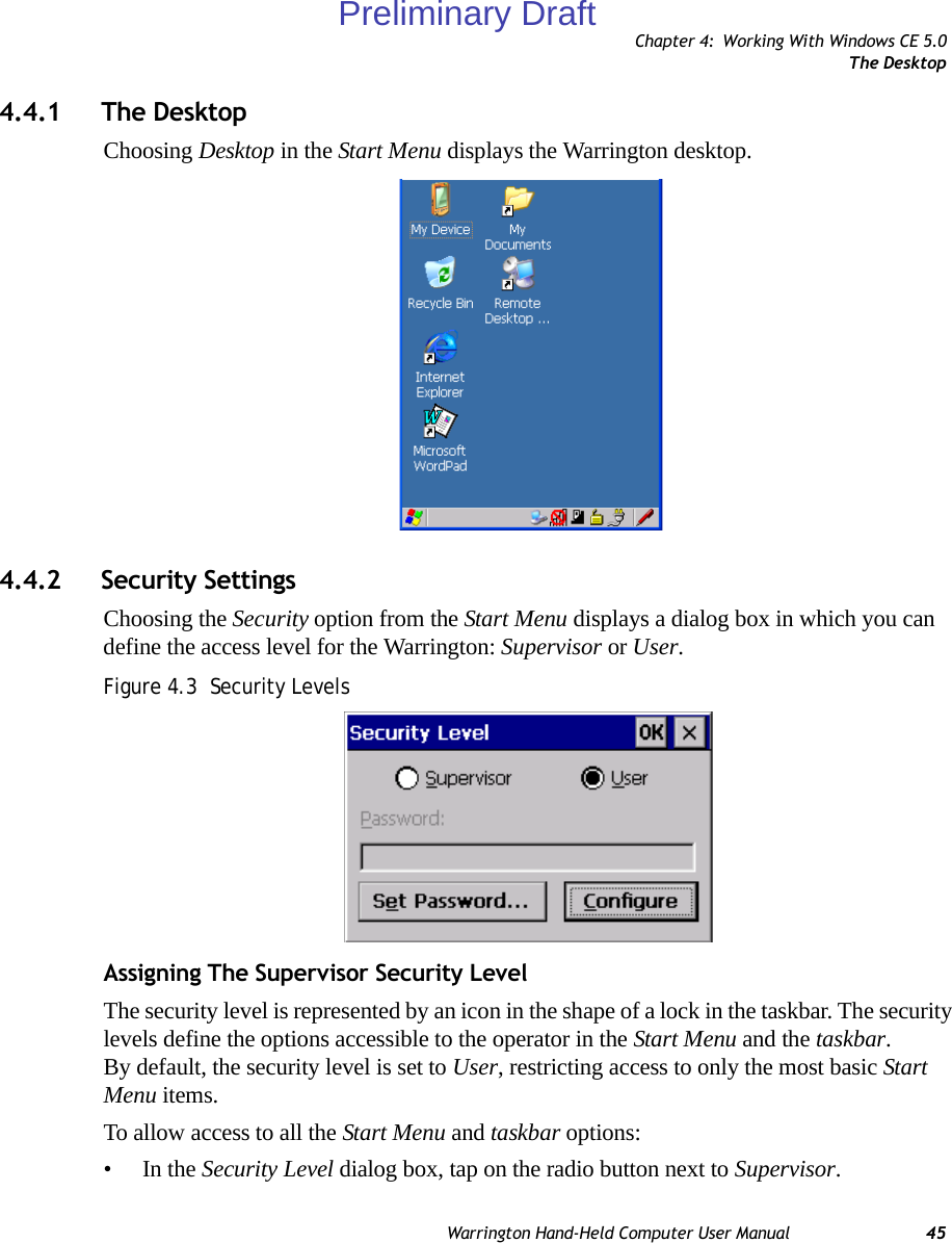
![Chapter 4: Working With Windows CE 5.0The Desktop Icons40 Warrington Hand-Held Computer User Manual4.3.1 The Desktop IconsThe icons displayed in the startup desktop operate in much the same way as those displayed on any standard PC desktop that is running Windows.My DeviceChoosing this icon displays the contents of your Warrington computer. If you’re not sure how to access the files, folders and programs displayed, refer to “Working With Files, Folders And Programs” on page 38.Recycle BinThis option temporarily stores items that were deleted, allowing you to either permanently delete or restore these items.Internet ExplorerChoosing this icon launches Internet Explorer—a standard Windows CE 5.0 version. Keep in mind that your supervisor will need to set up access using the Internet Options and the Network and Dial-up Connections icons in the Control Panel. Remote Desktop ConnectionThis option allows your Warrington to communicate with a remote desktop PC. “Remote Connect” on page 79 provides a website with step-by-step instructions. Note: If the arrow keys do not highlight the desktop icons, the desktop may not be selected. Press [FN/BLUE] [.] (period) to display the Start Menu, and select Desktop. Now the desktop will be “in focus” and the arrow keys will highlight the icons.Preliminary Draft](https://usermanual.wiki/Psion/PX750BT/User-Guide-963956-Page-52.png)
![Chapter 4: Working With Windows CE 5.0The TaskbarWarrington Hand-Held Computer User Manual 414.3.2 The TaskbarThe Warrington is equipped with a taskbar at the bottom of the screen. It displays icons through which you can view the battery capacity and radio signal quality of your unit. If the hand-held is attached to a charger, cradle, docking station or PDM, an associated icon is dis-played. In addition, the taskbar displays the application(s) currently running on your unit and the security level assigned to your Warrington.The taskbar also displays active modifier keys: [SHIFT], [ALT], [CTRL], [FN/BLUE] and [FN/ORANGE]. Keys that have been locked “on” are displayed in uppercase letters. For ex-ample, if you have set the [CTRL] key Lock to “on” in the Keyboard menu and you press the key, it is displayed as CTRL KEY in the taskbar. (For detailed information on modifier keys and keyboard options, see “The Keyboard” on page 60).4.3.2.1 Using The TaskbarA tooltip is displayed as each taskbar icon is highlighted. The tooltip provides the status of each icon.If you’re using the touchscreen:• Tap and hold the stylus on an icon to display the icon's tooltip. Double-tap the icon to open the Control Panel dialog box associated with the icon. For example, double-tap the battery icon to display a dialog box listing the current battery capacity information.On the keyboard:• Press [FN/BLUE] [.] (period) to display the Start Menu.• Choose Shortcuts from the Start Menu, and then press the [RIGHT] arrow key to display the sub-menu.Preliminary Draft](https://usermanual.wiki/Psion/PX750BT/User-Guide-963956-Page-53.png)
![Chapter 4: Working With Windows CE 5.0Customizing The Taskbar42 Warrington Hand-Held Computer User Manual• Choose System Tray in the sub-menu. • Use the arrow keys to highlight the icon in the taskbar about which you’d like more information.• Press [ENTER] to display the appropriate dialog box.4.3.2.2 Customizing The TaskbarTo customize the taskbar so that it displays only those icons you require:•In the Start Menu, choose Settings>Taskbar.If you’re using the keyboard:• Press [FN/BLUE] [.] to display the Start Menu.• Highlight the Settings option, highlight Taskbar in the sub-menu, and press [ENTER]. The Taskbar and Start Menu dialog box is displayed.Task bar G enera l Ta b• Tap the stylus on the items you want to activate or deactivate. The check mark indicates active items.If you’re using the keyboard:• Highlight the options you want to activate, and press the [SPACE] key to select them. The check mark indicates active items.Preliminary Draft](https://usermanual.wiki/Psion/PX750BT/User-Guide-963956-Page-54.png)
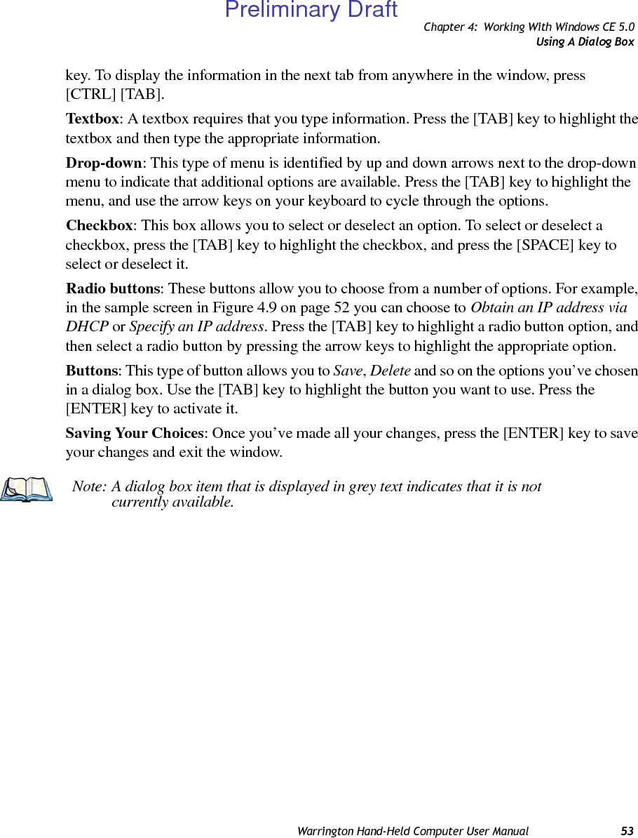
![Chapter 4: Working With Windows CE 5.0The Start MenuWarrington Hand-Held Computer User Manual 43Task bar A dvan ced Ta b• Tap on the Clear button to empty the Documents folder.• To display Control Panel applets in menu form rather than in a window, tap in the checkbox next to Expand Control Panel.Taskbar Security TabIf you check Disable hot keys, the Application from Start menu field becomes enabled. Use this field to enter the name of the application you want to run when the user presses the Menu hot key: [FN/BLUE] [0].If you have disabled hot keys, hidden the Start Menu and have no application configured, the Menu hot key brings up the Security dialog box to allow authorized users to access the hand-held configuration. Keep in mind that this dialog box is also displayed if an invalid ap-plication is entered in the Application from Start Menu field.4.4 The Start MenuNote: Some of the Start Menu items may be disabled based on the current Warrington security settings.Preliminary Draft](https://usermanual.wiki/Psion/PX750BT/User-Guide-963956-Page-55.png)
![Chapter 4: Working With Windows CE 5.0The Start Menu44 Warrington Hand-Held Computer User ManualThe Start Menu lists the operations you can access and work with. It is available from the startup desktop or from within any application.To display the menu:• Press [FN/BLUE] [.] (period).If you’re using the keyboard:• Use the arrow keys to highlight a menu item, and press [ENTER], or If the menu item has an underlined character:• Type the underlined alpha character. For example, to display the Security dialog box, type the letter ‘s’.Note: Tap on the item in the menu with which you want to work.Preliminary Draft](https://usermanual.wiki/Psion/PX750BT/User-Guide-963956-Page-56.png)
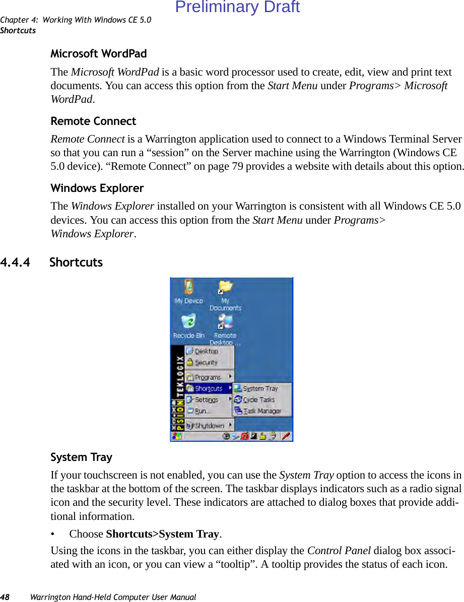
![Chapter 4: Working With Windows CE 5.0ShortcutsWarrington Hand-Held Computer User Manual 49• Tap and hold the stylus on an icon to display the icon’s tooltip. Double-tap on the icon to open the Control Panel dialog box associated with the icon.On the keyboard:• Press [FN/BLUE] [.] to display the Start Menu.• Choose Shortcuts from the Start Menu, and then press the [RIGHT] arrow key to display the sub-menu.• Choose System Tray in the sub-menu. • Use the arrow keys to highlight the icon in the taskbar about which you’d like more information. As each icon is highlighted, a tooltip is displayed.• To display the associated Control Panel dialog box, press [ENTER].Cycle TasksWhen Cycle Tasks is selected (and the Task Manager is not open), you can cycle through active applications. To cycle through your active applications:• Choose Shortcuts>Cycle Tasks, or Press [ALT] [TAB].Task Mana g erThe Task Manager allows you to switch to another task or to end an active task. To display the task manager window:• Tap on Shortcuts>Task Manager, orPress [ALT] [ESC].Figure 4.5 Task ManagerPreliminary Draft](https://usermanual.wiki/Psion/PX750BT/User-Guide-963956-Page-61.png)
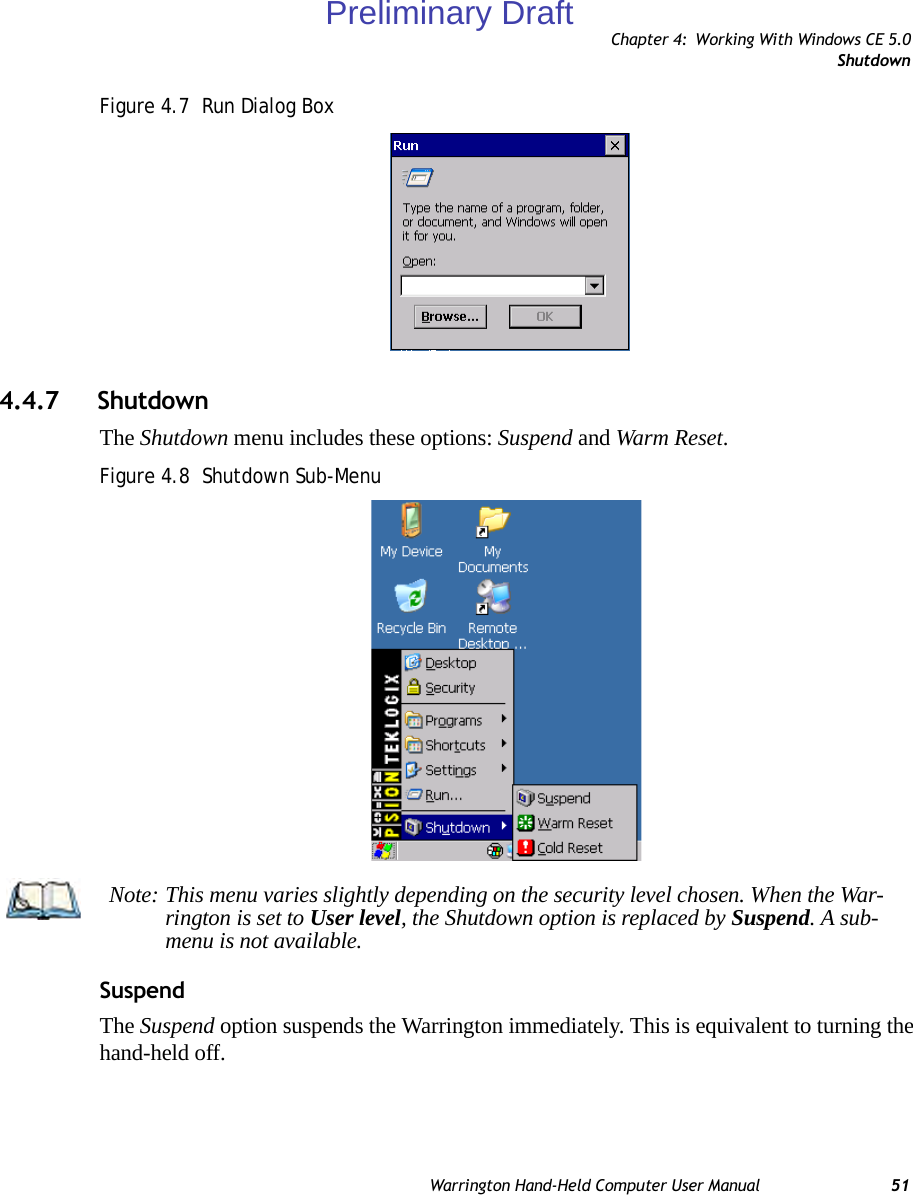
![Chapter 4: Working With Windows CE 5.0Using A Dialog Box52 Warrington Hand-Held Computer User ManualWarm ResetThe Warm Reset option resets the Warrington, leaving all saved files and (registry) settings intact. Any unsaved data is lost.Cold ResetThe Cold Reset option resets the Warrington, clearing all files not stored in permanent memory; however, the registry settings are saved.4.5 Using A Dialog BoxA dialog box (like the samples in Figure 4.9 on page 52) appears when you need to make se-lections and enter further information. You can move between dialog items by tapping on them with your stylus, or by pressing the arrow keys and the [TAB] key ([SHIFT] [TAB] moves the cursor backwards).Figure 4.9 Dialog BoxesDialog boxes contain one or more of the following elements:Tab: A tab separates different elements of a dialog box. Press the [TAB] key until a tab in the dialog box is highlighted. To display adjoining tabs, press the [RIGHT] or [LEFT] arrow CheckboxDrop-down MenuButtonTextboxRadioButtonTabsNote: You can use the stylus to tap on an element in a dialog box to select or deselect it, display drop-down menus, save your selections, and so on.Preliminary Draft](https://usermanual.wiki/Psion/PX750BT/User-Guide-963956-Page-64.png)
![Chapter 4: Working With Windows CE 5.0Using A Dialog BoxWarrington Hand-Held Computer User Manual 53key. To display the information in the next tab from anywhere in the window, press [CTRL] [TAB].Textbox: A textbox requires that you type information. Press the [TAB] key to highlight the textbox and then type the appropriate information.Drop-down: This type of menu is identified by up and down arrows next to the drop-down menu to indicate that additional options are available. Press the [TAB] key to highlight the menu, and use the arrow keys on your keyboard to cycle through the options. Checkbox: This box allows you to select or deselect an option. To select or deselect a checkbox, press the [TAB] key to highlight the checkbox, and press the [SPACE] key to select or deselect it.Radio buttons: These buttons allow you to choose from a number of options. For example, in the sample screen in Figure 4.9 on page 52 you can choose to Obtain an IP address via DHCP or Specify an IP address. Press the [TAB] key to highlight a radio button option, and then select a radio button by pressing the arrow keys to highlight the appropriate option.Buttons: This type of button allows you to Save, Delete and so on the options you’ve chosen in a dialog box. Use the [TAB] key to highlight the button you want to use. Press the [ENTER] key to activate it.Saving Your Choices: Once you’ve made all your changes, press the [ENTER] key to save your changes and exit the window.Note: A dialog box item that is displayed in grey text indicates that it is not currently available.Preliminary Draft](https://usermanual.wiki/Psion/PX750BT/User-Guide-963956-Page-65.png)

![Chapter 5: Getting To Know The WarringtonSwitching The Hand-Held On And Off60 Warrington Hand-Held Computer User Manual5.3 Switching The Hand-Held On And Off• To switch the unit on, press and hold down the [ENTER] key for at least one second. • When the LED flashes green, release the [ENTER] key.The startup screen is displayed.Switching Off The Warrington (Suspend)• To switch the unit off, press [FN/BLUE] [ENTER].5.4 The KeyboardTwo keyboard options are available:• 48-key alpha-numeric keyboard. This keyboard is only available with connected hand-helds – units equipped with 802.11b/g radios.• 26-key numeric keyboard. This option is available for both variants of Warrington – connected hand-helds (described above) and unconnected or batch hand-helds not equipped with 802.11b/g radios.Most of the keys on these keyboards operate much like a desktop computer. Where a key or key function is not consistent with the PC keyboard, the differences are noted.Note: Refer to “Monitoring The Battery And Maximizing Run Time” on page 70 for addi-tional information about the battery.Important: To avoid damaging the battery, chargers will not begin the charge process until the battery temperature is between 0°C to 45°C (32°F to 113°F).Note: If the Warrington is in suspend state, pressing [ENTER] ‘wakes’ the unit from this state. The screen in which you were working before the computer entered suspend state is displayed. Important: Keep in mind that turning off the Warrington does not result in a complete reboot; rather, the unit enters a power-saving, “suspend” state. When the unit is turned on from suspend state, operation resumes within a few seconds.Preliminary Draft](https://usermanual.wiki/Psion/PX750BT/User-Guide-963956-Page-72.png)
![Chapter 5: Getting To Know The WarringtonModifier KeysWarrington Hand-Held Computer User Manual 61The [FN/BLUE] and [FN/ORANGE] modifier keys provide access to additional keys and system functions. These functions are colour coded in orange and blue print above the keyboard keys.5.4.1 Modifier KeysThe [SHIFT], [CTRL], [ALT], [FN/BLUE] and [FN/ORANGE] keys are modifier keys. Pressing a modifier key changes the function of the next key pressed. The [SHIFT], [CTRL] and [ALT] keys operate much like a desktop keyboard except that they are not chorded (two keys held down simultaneously). The modifier key must be pressed first followed by the key whose function you want modified.5.4.1.1 Activating Modifier KeysWhen a modifier key is pressed once, it is displayed in lowercase letters in the taskbar at the bottom of the hand-held screen. For example, if the [CTRL] key is pressed, ctrl key is dis-played at the bottom of the unit screen. Once the next key is pressed, the modifier key becomes inactive and disappears from the taskbar. Keep in mind, however, that the ‘One Shot’ function allows you to determine how many key presses will lock a modifier key ‘on’ – one press or two. Refer to “Keyboard One Shot Modes” on page 90 for details.5.4.1.2 Locking Modifier KeysWhen a modifier key is pressed twice, it is ‘locked’ on. A ‘locked’ modifier key is displayed in uppercase letters in the taskbar. For example, pressing the [CTRL] key twice locks it on – it is displayed as CTRL KEY in the taskbar at the bottom of the computer screen.The locked modifier key will remain active until it is pressed a third time to unlock or turn it off. Once a modifier key is unlocked, the uppercase representation at the bottom of the screen is no longer displayed.5.4.2 The KeysThe [SHIFT] KeyThe [SHIFT] key is used to display uppercase alpha characters and provide access to the symbols above the numeric keys.Preliminary Draft](https://usermanual.wiki/Psion/PX750BT/User-Guide-963956-Page-73.png)
![Chapter 5: Getting To Know The WarringtonFunction Keys And Macro Keys62 Warrington Hand-Held Computer User ManualThe Arrow KeysThe Arrow keys move the cursor around the screen in the direction of the arrow: up, down, left and right. The cursor is the flashing box or underline character that indicates where the next character you type will appear.The [SPACE] KeyPressing this key inserts a blank space between characters. In a Windows dialog box, press-ing the [SPACE] key enables or disables a checkbox.The [BKSP/DEL] KeyThe [BKSP] key (sometimes referred to as destructive backspace) moves the cursor one character to the left, erasing the incorrectly entered key stroke. The [DEL] key ([FN/BLUE] [BKSP]) erases the character at the cursor position.The [CTRL] And [ALT] KeyThe [CTRL] and [ALT] keys modify the function of the next key pressed and are applica-tion-dependent. The [TAB] KeyTypically, the [TAB] key moves the cursor to the next field to the right or downward.The [ESC] KeyGenerally, this key is used as a keyboard shortcut to close the current menu, dialog box or activity and return to the previous one.The [SCAN] KeyAll units are equipped with a yellow [SCAN] key. For units that do not have internal scan-ners, this key can be re-mapped to another function.5.4.3 Function Keys And Macro KeysIn addition to the standard keyboard functions, the Warrington supports Function keys and Macro keys. All Function and Macro keys can be custom defined for each application. 5.4.3.1 Function KeysThe Warrington keyboard is equipped with a total of 14 function keys. Function keys [F1] to [F4] are located near the top of the keyboard on the [TAB], [ALT], [CTRL] and [ESC] keys and are directly accessible—a key combination is not required. Ten additional function keys Preliminary Draft](https://usermanual.wiki/Psion/PX750BT/User-Guide-963956-Page-74.png)
![Chapter 5: Getting To Know The WarringtonThe Macro KeysWarrington Hand-Held Computer User Manual 63are colour coded in blue print on the unit body; these keys are accessed by executing a key combination, [FN/BLUE] followed by the appropriate numeric key.For example, to access function key [F7]:• Press the [FN/BLUE] key followed by the [7] key—the numeric key to which function key [F7] is mapped.• To access function key [F8], press [FN/BLUE] [8], and so on.5.4.3.2 The Macro Keys While macro keys are not physically stamped on the keyboard, up to 12 macro functions can be added using the Scancode Remapping function. Refer to “Scancode Remapping” on page 94 for details about mapping keys. Refer to “Keyboard Macro Keys” on page 91 for details about programming characters in a Macro key.5.4.4 26-Key Keyboard: Accessing Alpha KeysOn numeric 26-key keyboards, numeric keys are directly accessible, and all alpha characters are printed on the unit plastic in orange characters above the numeric keys. An indicator in the left corner of the taskbar displays the currently selected character. To access an alpha character, first press the [FN/ORANGE] key and then press the numeric key above which the alpha character you want to type is printed. Choosing A Single Alpha CharacterThe examples below illustrate how to access, A, B, and C, all of which are printed in orange characters above the numeric key [2].To choose the letter a:• Press the [FN/ORANGE] key, and press the numeric key [2].To choose the second letter in the sequence—in this example, the letter b:Important: The letters you choose appear in the taskbar, providing a visual indicator of which letter will be displayed on the screen. Note: To choose the second, third or fourth alpha character assigned to a numeric key, you may want to lock the [FN/ORANGE] key ‘on’. By default, the [FN/ORANGE] key is locked ‘on’ when pressed once. However, depending on how your unit is set up in the ‘One Shots’ tab, you may find that you need to press the [FN/ORANGE] key twice to lock it ‘on’. Refer to “Keyboard One Shot Modes” on page 90 for details.Preliminary Draft](https://usermanual.wiki/Psion/PX750BT/User-Guide-963956-Page-75.png)
![Chapter 5: Getting To Know The WarringtonThe Keypad Backlight64 Warrington Hand-Held Computer User Manual• Lock the [FN/ORANGE] key ‘on’. ‘ORG KEY is displayed in upper-case characters in the taskbar to indicate that this key is locked ‘on’.• Press numeric key [2] twice to display the letter b.To choose the third letter in the sequence—in this example, the letter c:• Lock the [FN/ORANGE] key ‘on’. • Press numeric key [2] three times to display the letter c.Creating Uppercase LettersTo display a capital letter:• Press the [FN/ORANGE] key and then the [SHIFT] key before typing the alpha character.Choosing Multiple Alpha Characters• Lock the [FN/ORANGE] key ‘on’.Each time you press a numeric key from [2] through [9], an alpha character will be dis-played on the screen. Remember that you can refer to the softkey bar for a visual indication of which alpha key will be displayed on the screen.5.4.5 The Keypad BacklightThe intensity of the keypad backlight and the conditions under which this backlight is acti-vated can be configured using the Keyboard icon in the Windows CE 5.0 Control Panel. The behaviour of the keypad backlight is tailored in the Keyboard Properties dialog box. Refer to “Keyboard Backlight” on page 89 for details about this option.Note: Keep in mind that there is a timeout if you pause for one second between key presses when selecting the second, third or fourth letters on a key. For example, suppose you want to type the letter ‘c’ – you’d need to press the [2] key three times. With the [FN/ORANGE] key locked ‘on’, if you press [2] twice and then pause between key presses for 1 second, the letter ‘b’ will be selected automatically.Note: If you want to use uppercase characters at all times, press [FN/BLUE] [SHIFT]. An icon of an uppercase ‘A’ is displayed in the taskbar indicating that all letters will be displayed as uppercase characters.Important: Once you have finished typing alpha characters, remember to turn off or unlock the [FN/ORANGE] key.Preliminary Draft](https://usermanual.wiki/Psion/PX750BT/User-Guide-963956-Page-76.png)
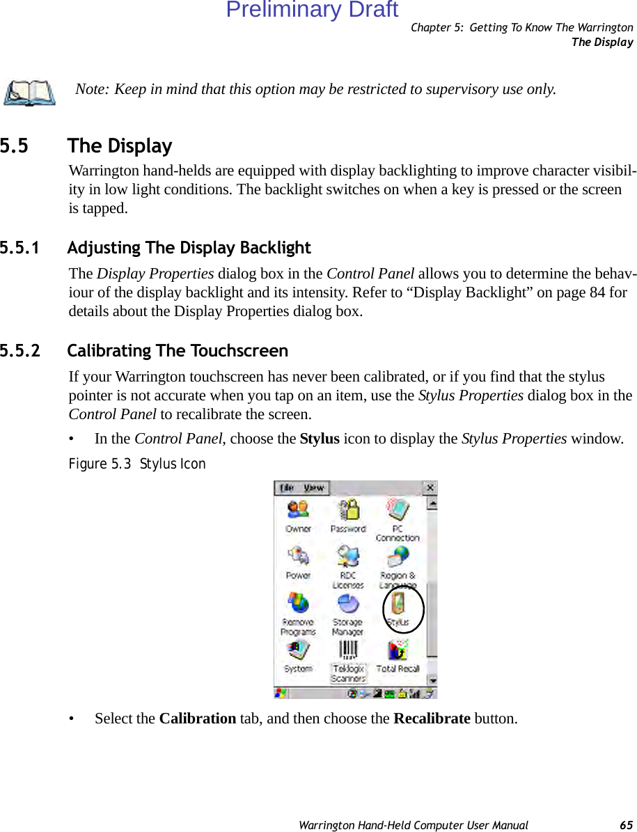
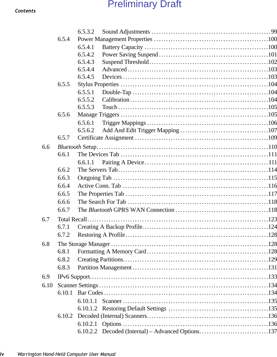
![Chapter 5: Getting To Know The WarringtonWarrington Hand-Held Indicators66 Warrington Hand-Held Computer User ManualFigure 5.4 Calibration Screen• Follow the directions on the calibration screen to calibrate the screen.5.6 Warrington Hand-Held IndicatorsThe Warrington uses an LED (Light Emitting Diode), onscreen messages and audio tones to indicate the various conditions of the hand-held, the batteries, the scans and so on.5.6.1 LEDsA tri-coloured LED is located on the upper-left side of the unit, above the screen. The green LED is the battery charge indicator; the yellow LED indicates an application; the blue LED indicates whether the radio is on or off. When you press [ENTER], the LED flashes green to indicate that the unit has been powered up. The LED table following outlines the behaviour of the LED while the unit is docked in a charger.Keep in mind that the application running on the Warrington can dictate how the LED oper-ates. Review the documentation provided with your application to determine LED behaviour. If the unit is attached to an external power supply, the hand-held’s LED reflects the battery charge status.Preliminary Draft](https://usermanual.wiki/Psion/PX750BT/User-Guide-963956-Page-78.png)
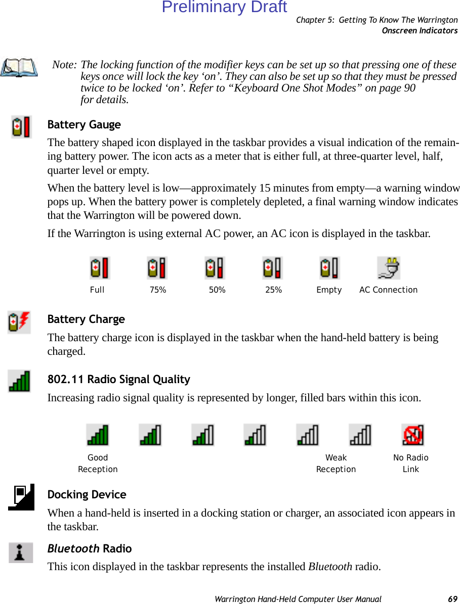
![Chapter 5: Getting To Know The WarringtonAudio IndicatorsWarrington Hand-Held Computer User Manual 675.6.2 Audio IndicatorsThe audio speaker provides a variety of sounds when a key is pressed, a keyboard character is rejected, scan input is accepted or rejected, an operator’s entry does not match in a match field or the battery is low. To specify how you want your Warrington to respond under various conditions, refer to “Volume And Sound Properties” on page 98.The volume keys are located above the [UP ARROW] and [DOWN ARROW] keys. The in-crease volume key is labelled with a plus symbol and the decrease volume key is labelled with a minus symbol .5.6.2.1 Adjusting The Warrington Speaker Volume• Lock the [FN/BLUE] key ‘on’ and then, press [UP ARROW] – the increase volume key or [DOWN ARROW] – the decrease volume key until the volume meets your requirements.• Remember to press the [FN/BLUE] key again to turn it ‘off’.5.6.3 Onscreen IndicatorsThe taskbar at the bottom of the screen displays a variety of system status indicators.Table 5.1 Warrington LED BehaviourLED Behaviour Charge StatusSolid Green Charge complete.Fast Blinking Green Charge in progress. Battery charged to less than 80% capacity.Slow Blinking Green Battery charged to greater than 80% of capacity.Solid Red Temperature outside charge range (0°C to 50°C).Blinking Red Battery is not charging. Battery fault.Preliminary Draft](https://usermanual.wiki/Psion/PX750BT/User-Guide-963956-Page-79.png)
![Chapter 5: Getting To Know The WarringtonOnscreen Indicators68 Warrington Hand-Held Computer User ManualFigure 5.5 TaskbarThe taskbar changes dynamically, and only those icons that are applicable are displayed. For example, if a radio is not installed in your Warrington, the radio signal icon is not displayed in the taskbar.Windows® Start ButtonIf you are using the touchscreen, you can either tap the Windows icon at the bottom left of the screen, or press [FN/BLUE] [.] (period) to display the Start Menu, and then tap on the desired application.Modifier Key Indicators[SHIFT], [CTRL], [ALT], [FN/BLUE] and [FN/ORANGE] are modifier keys that when pressed, are displayed in the taskbar to indicate that they are active. If a modifier key is locked ‘on’, it is displayed in uppercase characters. For example, if the [FN/BLUE] key is locked on, it is displayed as BLUE KEY in the taskbar. A locked modifier key remains active until it is pressed again to unlock or turn it off. If a modifier key has been pressed but is not locked on, it is displayed in the taskbar in low-ercase characters – for example, blue key. It will remain active only until the next key is pressed at which point, the modifier key is turned off.Preliminary Draft](https://usermanual.wiki/Psion/PX750BT/User-Guide-963956-Page-80.png)
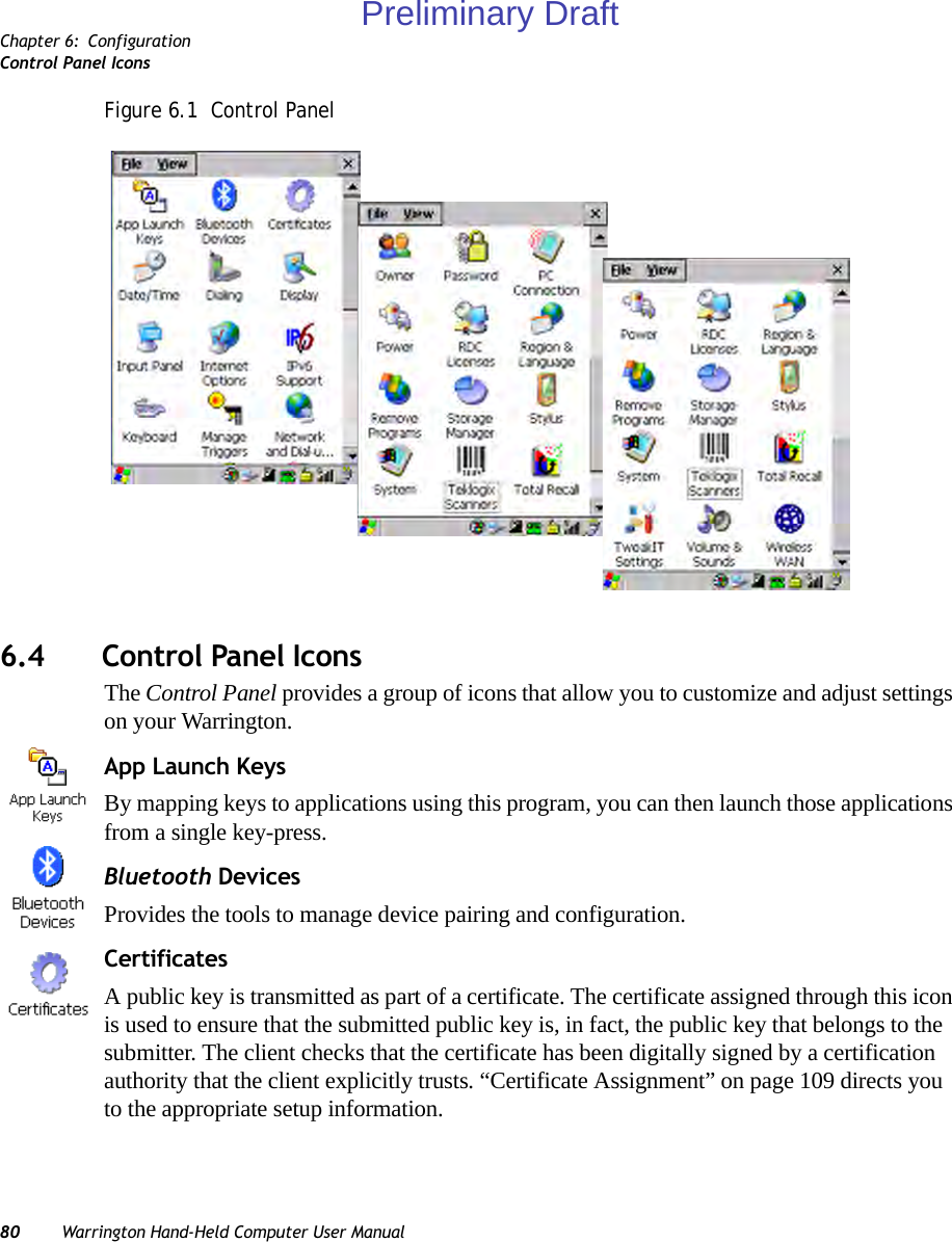
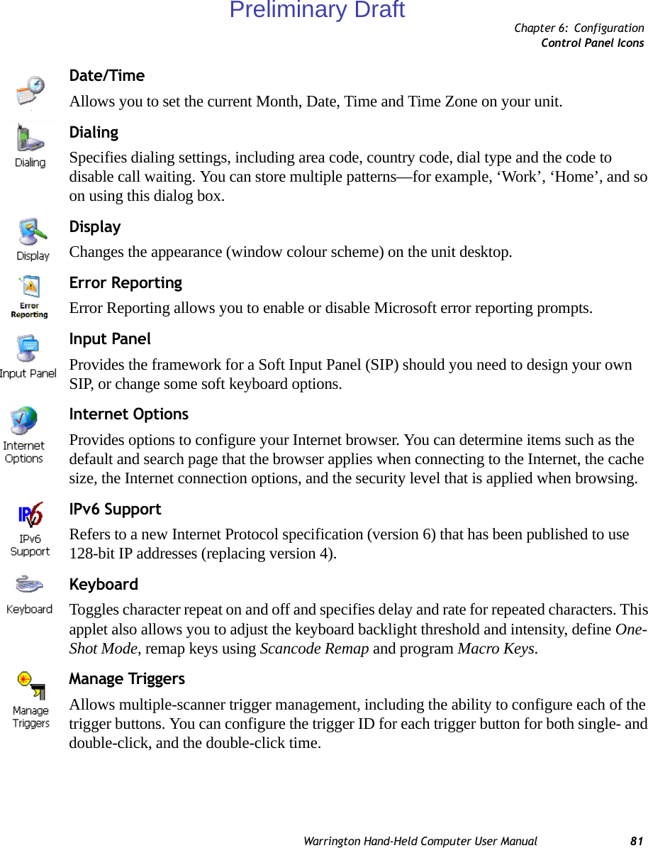
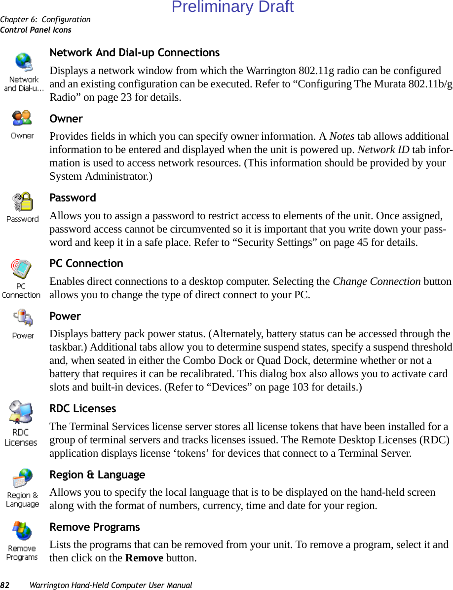
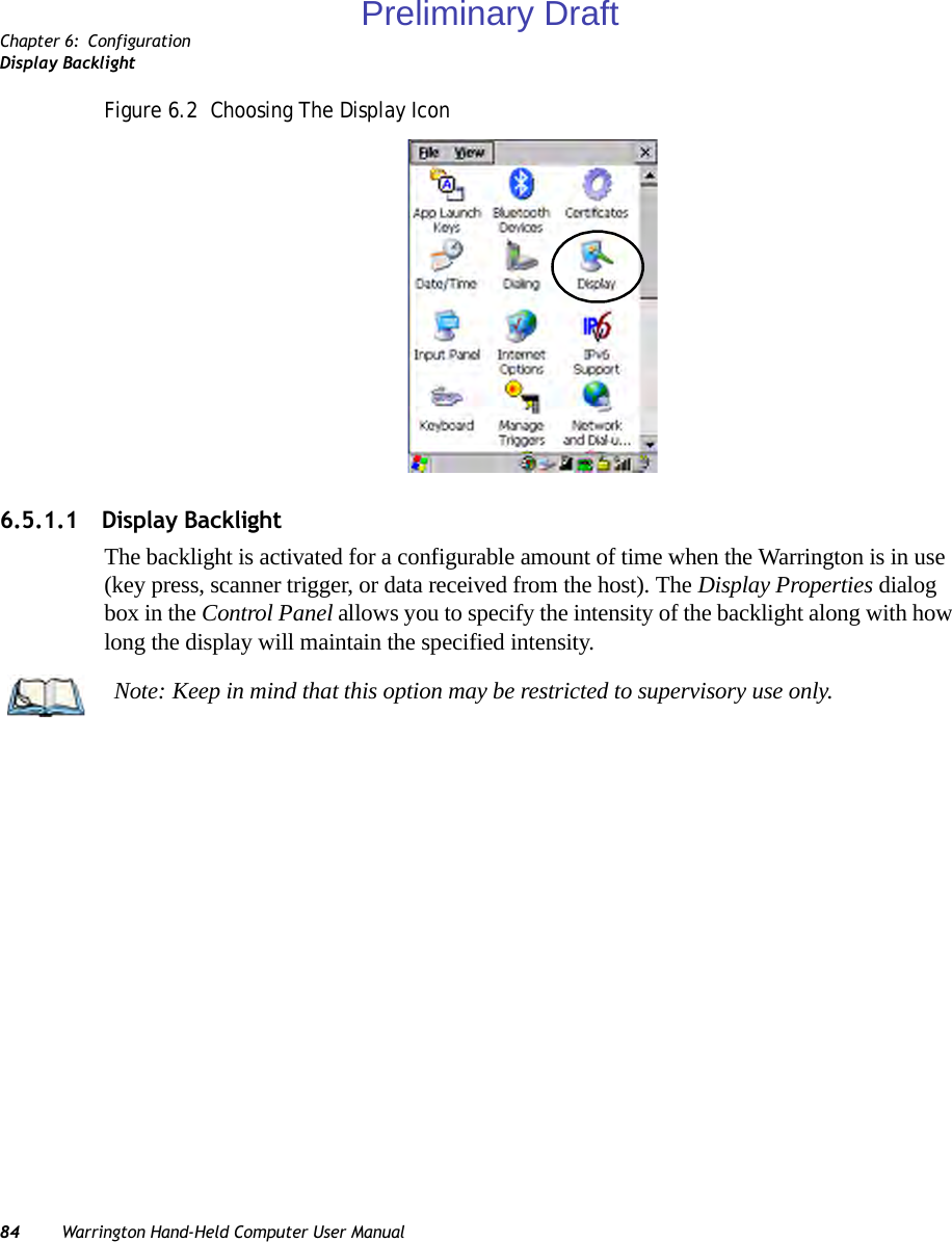
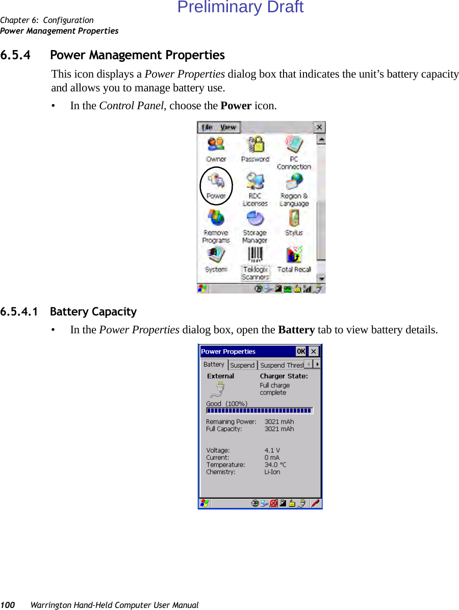
![Chapter 6: ConfigurationRemote ConnectWarrington Hand-Held Computer User Manual 796.1 Remote Connect Remote Connect is a Warrington application used to connect to a Windows Terminal Server so that you can run a “session” on the Server machine, using the Warrington (Windows CE 5.0 device). Refer to the following website for step-by-step information about setting up this connection: http://www.microsoft.com/WindowsXP/pro/using/howto/gomobile/remotedesktop/default.aspor contact Psion Teklogix support services. (Locate the office closest to you at: www.psionteklogix.com).6.2 The TekTerm ApplicationTekTerm is a powerful emulation application ideally suited for real time data transaction ap-plications associated with mainframes and servers. The Warrington includes unique features that support TekTerm—a Psion Teklogix application that has the ability to maintain multiple simultaneous sessions with a variety of host computers. For detailed information, please refer to the TekTerm Software User Manual, PN 8000073.6.3 The Control PanelThe Windows CE 5.0 Control Panel provides a group of icons through which you can set a variety of system-wide properties, such as mouse sensitivity, network configuration and the desktop color scheme.When the Warrington boots up, the startup desktop (shell) is displayed, and any applications stored in the Startup folder start up immediately. To access the Control Panel:• Tap on Start>Settings>Control Panel.If you’re using the keyboard:• Press [FN/BLUE] [.] to display the Start Menu.• Highlight Settings in Start Menu, and press the [RIGHT] arrow key to highlight the Control Panel.• Press the [ENTER] key.The Control Panel folder contains icons used in the setup of your Warrington.Note: If you are uncertain how to move around a dialog box and make selections, review “Using A Dialog Box” on page 52.Preliminary Draft](https://usermanual.wiki/Psion/PX750BT/User-Guide-963956-Page-91.png)
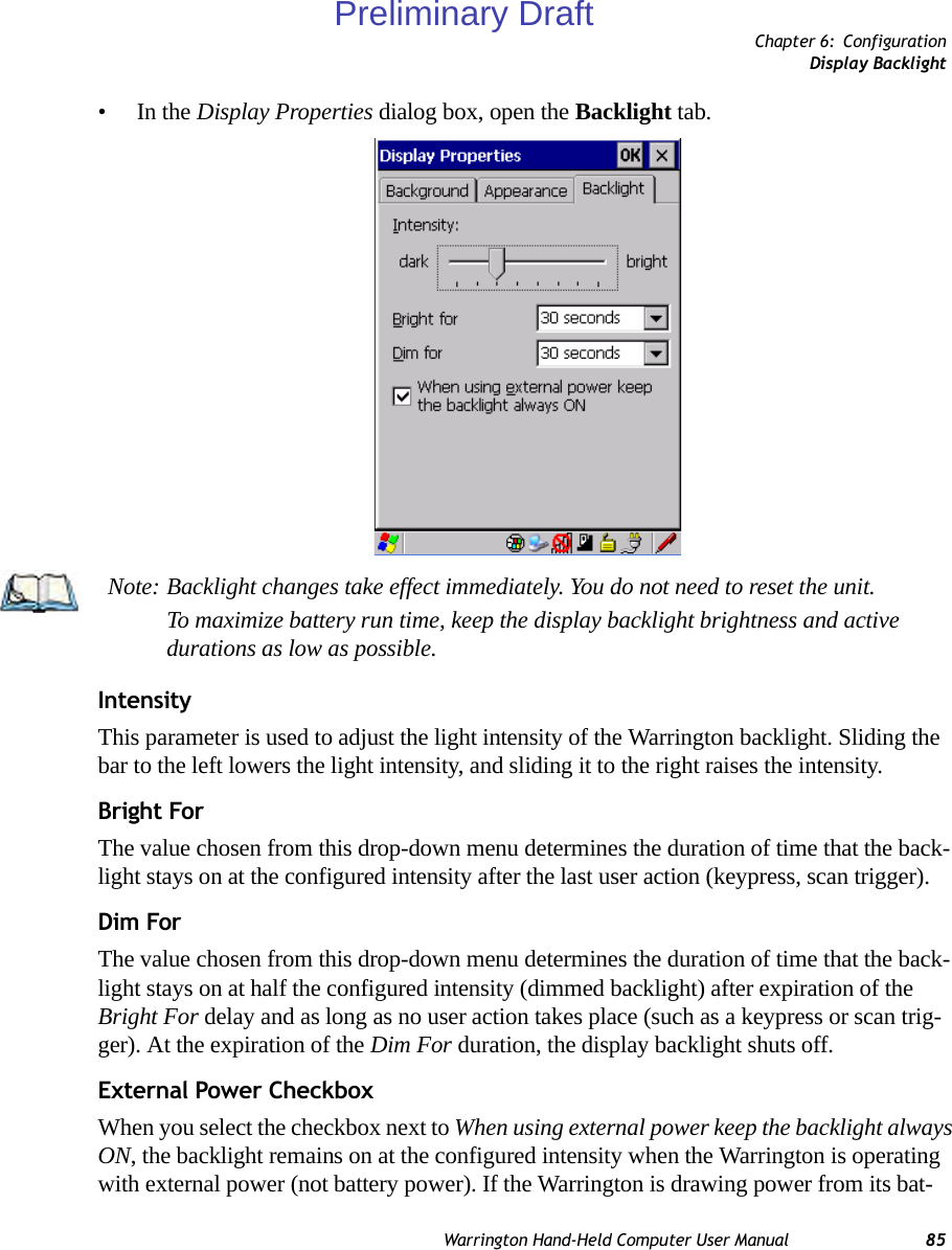
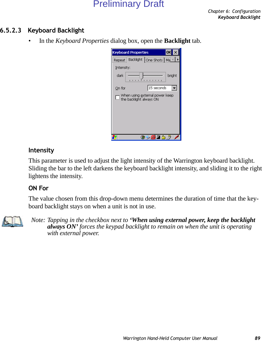
![Chapter 6: ConfigurationDisplay Appearance86 Warrington Hand-Held Computer User Manualtery, this option is ignored and the other parameters defined in Display Properties dialog box are used.6.5.1.2 Display Appearance•In the Display Properties dialog box, open the Appearance tab.This dialog box allows you to customize the display colour scheme.6.5.2 Keyboard PropertiesThis icon displays the Keyboard Properties dialog box in which you can adjust the repeat rate of the keys, the intensity of the keyboard backlight and the behaviour of the [FN/BLUE] and [FN/ORANGE] modifier keys. This dialog box also allows you to define macro keys and Unicode characters.•In the Control Panel, choose the Keyboard icon.Preliminary Draft](https://usermanual.wiki/Psion/PX750BT/User-Guide-963956-Page-98.png)
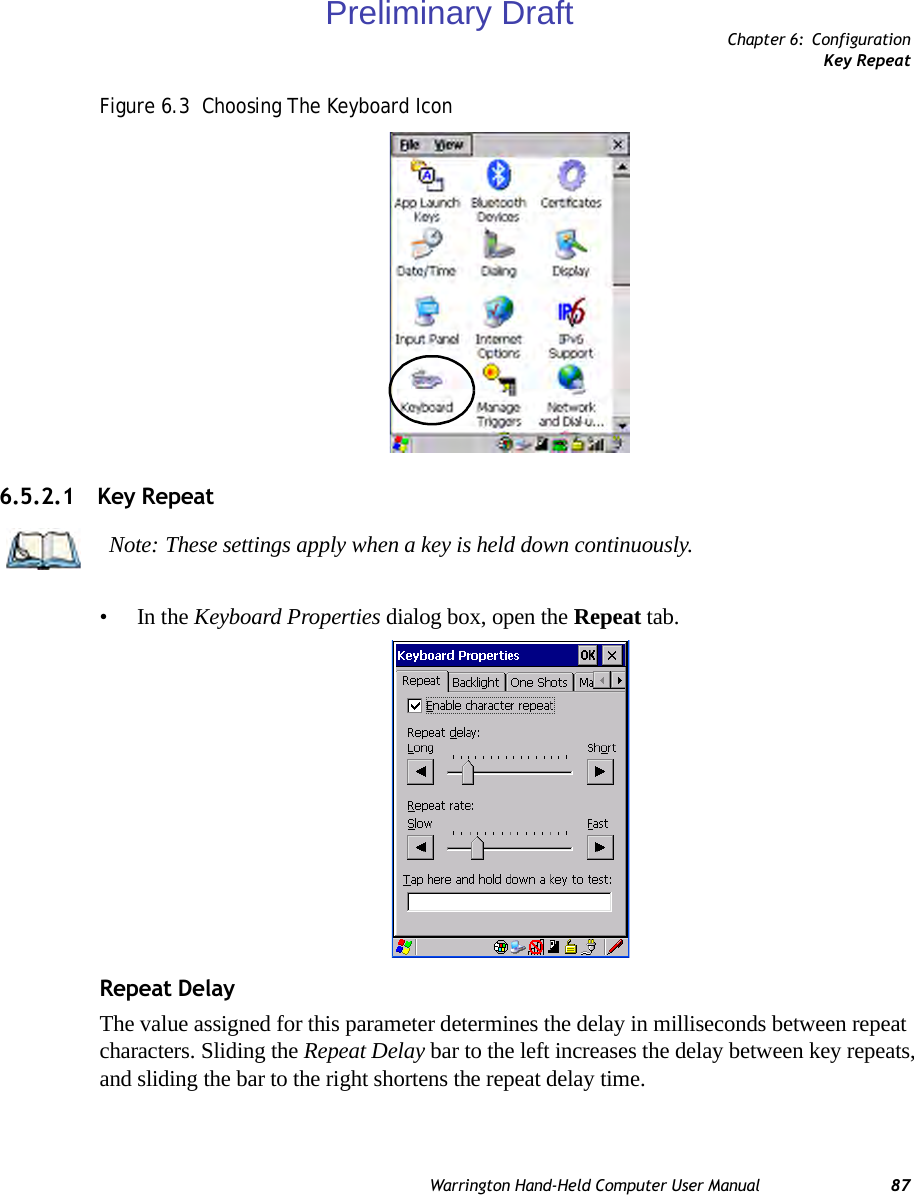
![Chapter 6: ConfigurationSequence88 Warrington Hand-Held Computer User ManualRepeat RateThe value assigned for the Repeat Rate parameter determines how quickly the key you press repeats and is measured in characters per second (cps). Sliding the bar to the left slows the repeat rate, and sliding the bar to the right increases the repeat rate.6.5.2.2 SequenceThis tab determines the allowable pause between alpha key presses on a numeric keypad. For example, suppose you want to type the letter ‘c’ – you would need to press the [2] key three times. With the [ORANGE] key locked ‘on’, if you press [2] twice and then pause between key presses for 1 second, the letter ‘b’ will be selected automatically. Moving the Sequence slider to the right increases the pause time between alpha key presses.Note: Use the field at the bottom of this dialog box to test the repeat delay and rate set-tings you’ve chosen.Preliminary Draft](https://usermanual.wiki/Psion/PX750BT/User-Guide-963956-Page-100.png)
![Chapter 6: ConfigurationKeyboard One Shot Modes90 Warrington Hand-Held Computer User Manual6.5.2.4 Keyboard One Shot Modes•In the Keyboard Properties dialog box, open the One Shots tab.The options in this tab allow you to determine how modifier keys on your Warrington behave. For each modifier key—[ALT], [SHIFT], [CTRL], [FN/ORANGE] and [FN/BLUE] – you have the following options in the drop-down menu: Lock, OneShot, and OneShot/Lock. LockIf you choose Lock from the drop-down menu, pressing a modifier key once locks it ‘on’ until you press the modifier key a second time to unlock or turn it off. OneShotIf you choose OneShot, the modifier key remains active only until the next key is pressed.Note: Keep in mind that checking the taskbar lets you know whether or not these keys are locked on. For example, if the [FN/ORANGE] key is locked ‘on’, the taskbar at the bottom of the screen displays it in uppercase characters, ORANGE KEY. If this key is displayed in lowercase characters in the taskbar, you’ll know that the orange key is not locked. It will become inactive following a key press.Important: Once you’ve assigned a One Shot mode to a modifier key, you need to tap on the OK button at the top of the tab to activate your selection.Preliminary Draft](https://usermanual.wiki/Psion/PX750BT/User-Guide-963956-Page-102.png)
![Chapter 6: ConfigurationKeyboard Macro KeysWarrington Hand-Held Computer User Manual 91OneShot/LockOneShot/Lock allows you to combine these functions. When you choose this option and you press the modifier key once, it remains active only until the next key is pressed. If you press the modifier key twice, it is locked ‘on’, remaining active until the modifier key is pressed a third time to turn it ‘off’.6.5.2.5 Keyboard Macro Keys•In the Keyboard Properties dialog box, open the Macros tab.A macro has 200 programmable characters (or “positions”). The macro keys can be pro-grammed to replace frequently used keystrokes, along with the function of executable keys including [ENTER], [BKSP] and [DEL] ([FN/BLUE]-[BKSP]), function keys and arrow keys.Recording And Saving A MacroOn the 36-key Warrington, you can program a maximum of 6 macro keys.•In the Macro menu highlight a macro key number, for example macro 1, to assign a macro to macro key [M1]. Choose the Record button. Preliminary Draft](https://usermanual.wiki/Psion/PX750BT/User-Guide-963956-Page-103.png)
![Chapter 6: ConfigurationKeyboard Macro Keys92 Warrington Hand-Held Computer User ManualA message screen is displayed instructing you to Enter Key Strokes to Record• Type the macro sequence you want to assign to the Macro key. You can type text and numbers, and you can program the function of special keys into a macro.• When you’ve finished recording your macro sequence, press the key sequence: [CTRL] [ALT] [ENTER], or choose the Stop Recording button.A new screen called ‘Verify Macro’ displays the macro sequence you created. The Save button is highlighted. • Press [ENTER] to save your macro, or highlight CANCEL and press [ENTER] to discard it.Executing A MacroTo execute a macro:• Press the macro key to which you’ve assigned the macro. For example, if you created a macro for macro key 1, press [M1] to execute the macro.Deleting A MacroTo delete a macro:•In the Macros tab, highlight the macro number you want to delete.• Choose the Delete button.Preliminary Draft](https://usermanual.wiki/Psion/PX750BT/User-Guide-963956-Page-104.png)
![Chapter 6: ConfigurationUnicode MappingWarrington Hand-Held Computer User Manual 936.5.2.6 Unicode Mapping•In the Keyboard Properties dialog box, open the Unicode Mapping tab.The Unicode Mapping tab is used to map combinations of virtual key values and [CTRL] and [SHIFT] states to Unicode™ values. This tab shows the configured Unicode character along with the Unicode value. For example, the sample screen above shows “a (U+0061)” indicating that the character “a” is represented by the Unicode value “0061”, and so on. Keep in mind that Unicode configurations are represented as hexadecimal rather than decimal values.All user-defined Unicode mappings are listed in the Unicode Mapping tab in order of virtual key value, and then by order of the shift state. If a Unicode mapping is not listed, the Unicode mapping is mapped to the default Unicode value.Adding And Changing Unicode Values• Choose the Add/Change buttonImportant: Changes to Unicode mappings are not saved until you exit the Keyboard Properties dialog box.Preliminary Draft](https://usermanual.wiki/Psion/PX750BT/User-Guide-963956-Page-105.png)
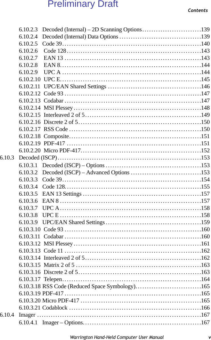
![Chapter 6: ConfigurationScancode Remapping94 Warrington Hand-Held Computer User ManualFigure 6.4 Adding And Changing Unicode Values• Highlight a value in the Unicode mapping list. In the sample screen above, a value will be assigned to virtual key 0 (VK 0).• Position the cursor in the Unicode Mapping field, and type a Unicode value for the highlighted key.Removing Unicode Values•In the Unicode Mapping tab, highlight the item you want to delete, and choose the Remove button.6.5.2.7 Scancode RemappingA scancode is a number that is associated with a physical key on a keyboard. Every key has a unique scancode that is mapped to a virtual key, a function or a macro. Scancode Remap-ping allows you to change the functionality of any key on the keyboard. A key can be remapped to send a virtual key (e.g. VK_F represents the ‘F’ key; VK_RETURN represents the [ENTER] key, etc.), perform a function (e.g. turn the scanner on, change volume/con-trast, etc.) or run a macro.There are three different tables of scancode mappings: the Normal table, the Blue table and the Orange table. The Normal table defines unmodified key presses; the Blue table defines Note: To add a shifted state, [SHIFT] and/or [CTRL], press [TAB] to position the cursor in the checkbox next to ‘SHIFT Pressed’ and/or ‘CTRL Pressed’. Press [SPACE] to select the shift state you want to assign.Preliminary Draft](https://usermanual.wiki/Psion/PX750BT/User-Guide-963956-Page-106.png)
![Chapter 6: ConfigurationScancode RemappingWarrington Hand-Held Computer User Manual 95key presses that occur when the [FN/BLUE] modifier is on; the Orange table defines key presses that occur when the [FN/ORANGE] modifier is on. The default mappings of these scancodes can be overwritten for each of these three tables using the Scancode Remapping tab accessed from the Keyboard Properties dialog box.The first column in the Scancode Remapping tab displays the scancodes in hexadecimal. If the scancode is remapped to a virtual key, that virtual key is displayed in the next column la-belled ‘V-Key’. A virtual key that is ‘Shifted’ or ‘Unshifted’ is displayed in the third column labelled ‘Function’. If the scancode is remapped to a function or a macro, the first and second columns remain blank while the third column contains the function name or macro key number (e.g., Macro 2).Adding A RemapTo add a new remapping:• Choose the Add button at the bottom of the dialog box.Preliminary Draft](https://usermanual.wiki/Psion/PX750BT/User-Guide-963956-Page-107.png)
![Chapter 6: ConfigurationScancode Remapping96 Warrington Hand-Held Computer User ManualThe Remap Scancode dialog box is displayed.• Type the scan code in hexadecimal in the field labelled ScancodeVirtual Key, Function And MacroThe radio buttons at the bottom of the dialog box allow you to define to what the scan code will be remapped: Virtual Key, Function or Macro. When Virtual Key is selected, you can choose to force [SHIFT] to be on or off when the virtual key is sent. If No Force is selected, the shift state is dependent on whether the shift state is on or off at the time the virtual key is sent.When Function is selected, a list of valid functions appears in the dialog box. When Macro is selected, the macro keys available on your unit are listed in the dialog box.• Choose Virtual Key, Function or Macro.• Choose a function from the Function list in the dialog box, and tap on OK.Editing A Scancode RemapTo edit a scancode:•In the Scancode Remapping tab, tap the stylus on the remap you want to edit.• Tap on the Edit button, and make the appropriate changes.• Tap on OK to save your changes.Note: The Label field displays the default function of the scancode you are remapping.Preliminary Draft](https://usermanual.wiki/Psion/PX750BT/User-Guide-963956-Page-108.png)
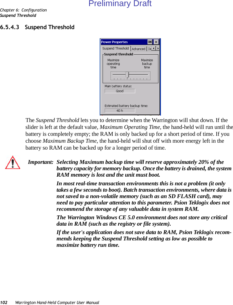
![Chapter 6: ConfigurationPower Saving SuspendWarrington Hand-Held Computer User Manual 1016.5.4.2 Power Saving Suspend•In the Power Properties dialog box, open the Suspend tab.Power SourceThis dialog box allows you to specify the suspend time for either AC Power or Battery Power.Suspend TimeoutWhen the Warrington is idle – not receiving any user input (a key touch, a scan, and so on) or system activity (serial data, an activity initiated by an application, and so on) – the hand-held uses the value assigned in the Suspend Timeout field to determine when the unit will go to sleep (appear to be off). When the time in the Suspend Timeout field elapses without any activity, the unit enters suspend state. In suspend state, the Warrington CPU enters a sleep state, and the radio is shut off. The state of the device (RAM contents) is preserved. Pressing [ENTER] wakes the system from suspend state. When the Warrington is in suspend state, the network connection will not be broken immediately. If the connection is dropped, you must re-establish the network connection.Important: Psion Teklogix recommends setting the Suspend value to 10 minutes. To further reduce power consumption, carefully consider the duration of time that the display backlight is ‘on’ (see “Display Backlight” on page 84).Preliminary Draft](https://usermanual.wiki/Psion/PX750BT/User-Guide-963956-Page-113.png)
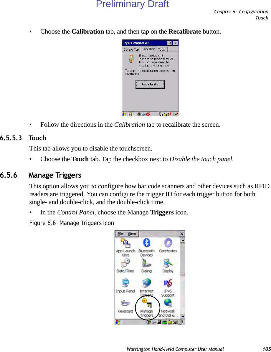
![Chapter 6: ConfigurationTrigger Mappings106 Warrington Hand-Held Computer User Manual•In the Manage Triggers screen you’ll see a list of trigger mappings.6.5.6.1 Trigger MappingsA trigger mapping is an association between a particular key on the keyboard and a driver or application, the module(s) – sometimes referred to as “trigger consumer(s)” – of the trigger source. Along with keyboard keys, trigger sources can also be grip triggers, external hard-ware triggers or software-based. When the specified key is pressed, the trigger consumer (for example, a decoded scanner) is sent a message.Double-ClickWhen a key is pressed and released, then pressed again within the configured time (between 0 to 1000 milliseconds), a double-click occurs. See also “Trigger-Press Type” on page 108.Show All ModulesBy default, the trigger mapping list only shows active mappings. Mappings for drivers or applications that are not currently active are not normally displayed. By checking this checkbox, all mappings, both active and inactive, are displayed.Important: It is not possible to have two or more identical mappings—for example [F1] cannot be mapped to the Non-Decoded Scanner twice—even if the trigger type is different.A keyboard key that is used as a trigger source will no longer generate key data or perform its normal function. For example, if the space button is used as a trigger source, it will not be able to send space characters to applications.Preliminary Draft](https://usermanual.wiki/Psion/PX750BT/User-Guide-963956-Page-118.png)
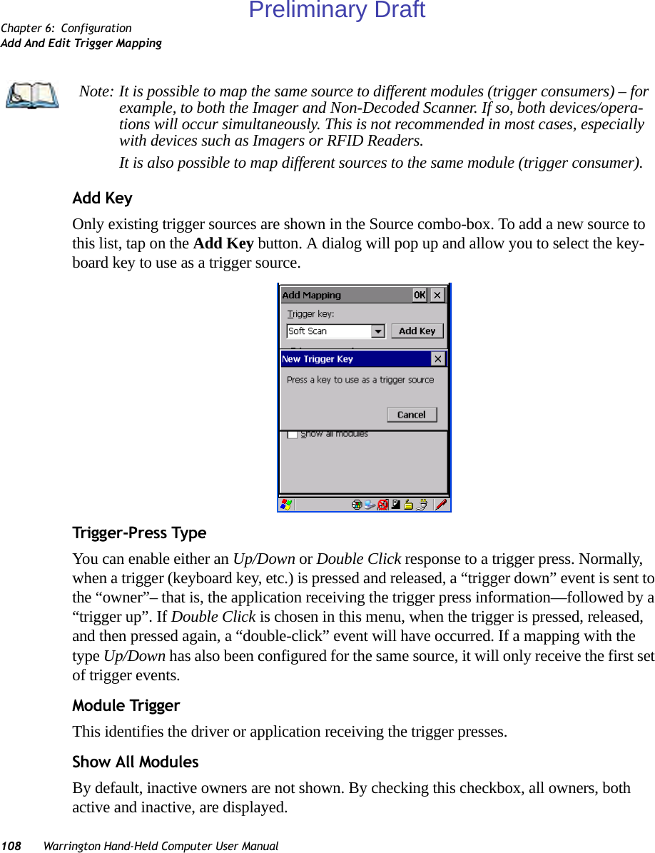
![Chapter 6: ConfigurationAdd And Edit Trigger MappingWarrington Hand-Held Computer User Manual 107AddTapping this button brings up the Add Mapping dialog (see “Add And Edit Trigger Map-ping” on page 107), so that you can add new trigger mappings.EditTapping this button brings up the Edit Mapping dialog (see “Add And Edit Trigger Map-ping” on page 107), so that you can edit existing trigger mappings.RemoveTapping this button removes an existing mapping.OKThe OK button in the top right of the Manage Triggers screen saves all changes made. If the cancel button X is tapped instead, or the [ESC] key is pressed, all changes made will be discarded.6.5.6.2 Add And Edit Trigger MappingThese dialogs allow the user to add and edit trigger mappings. Trigg er KeyThis drop-down list allows you to specify the source of the trigger events, such as the Grip Trigger, Left Scan, etc., for the trigger module selected.Preliminary Draft](https://usermanual.wiki/Psion/PX750BT/User-Guide-963956-Page-119.png)
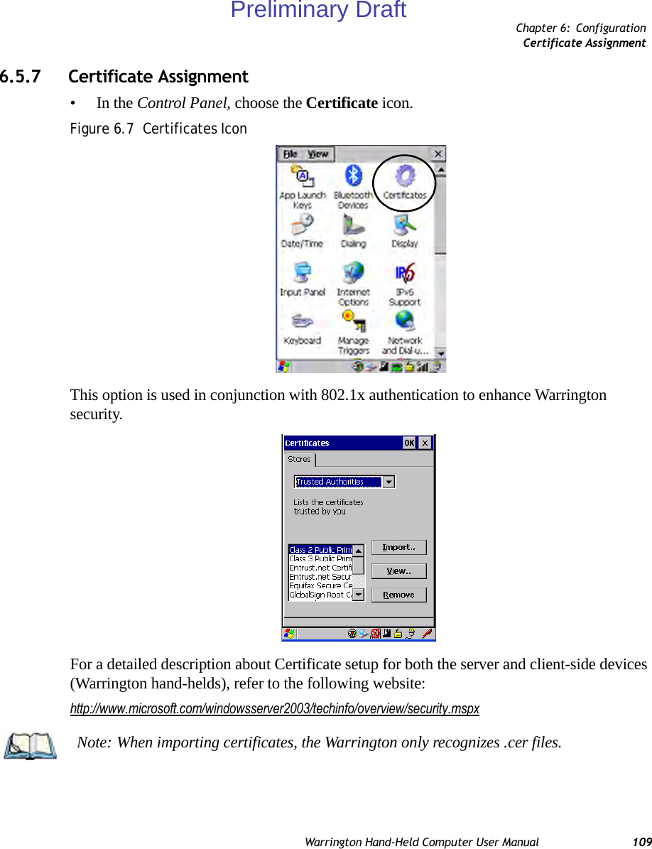
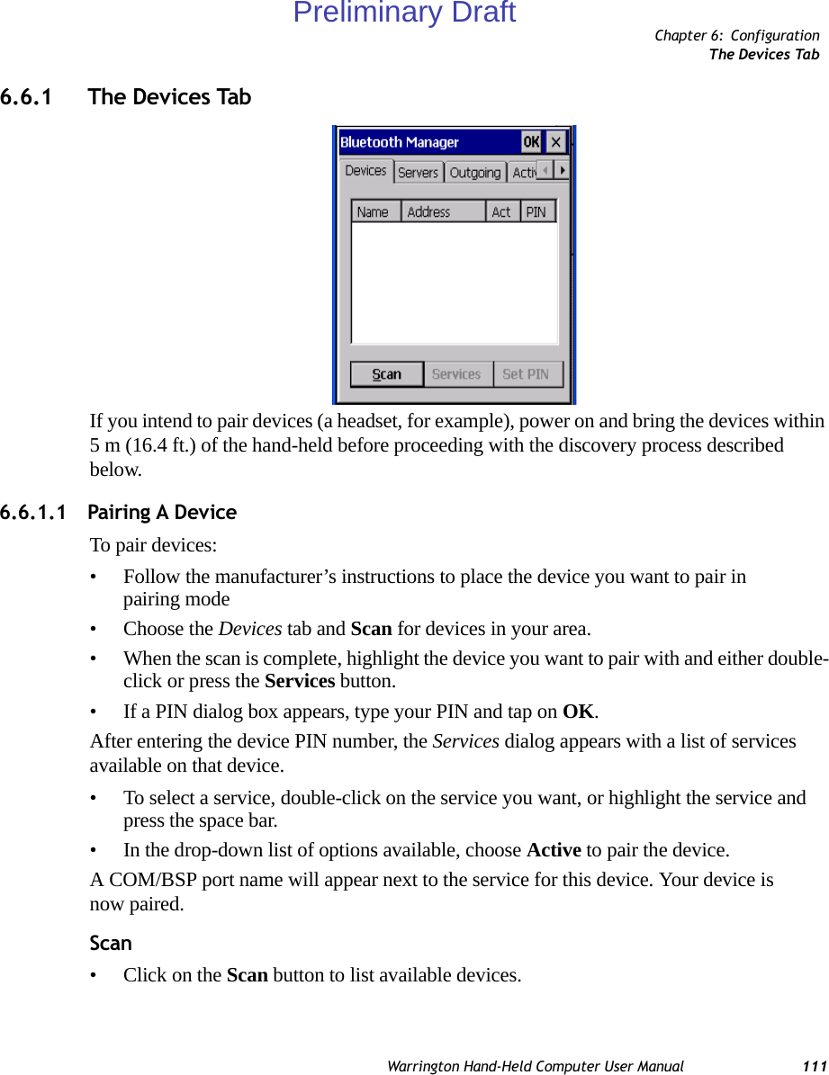
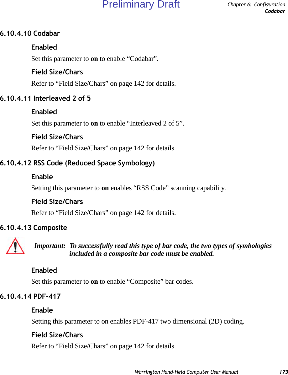
![Chapter 6: ConfigurationPairing A DeviceWarrington Hand-Held Computer User Manual 113Once the device’s service profiles are displayed in the Services list box:• Highlight the service to be activated.• Press [SPACE] or right-click to display the Activation menu.The Activation menu contains four options: Activate, Authenticate, Outgoing, and Encrypt.Once the service is successfully activated, the assigned port (if applicable) will appear in the Port column of the Services list box. You can choose to use BSP or COM as the port name. BSP is the latest Microsoft Bluetooth stack standard, but older applications assume serial ports are COM. When using COM as the port name, the Bluetooth manager will try to find and use a free port between COM7 and COM9. When using BSP as the port name, BSP2 to BSP9 are available for use. The port is available as soon as it is activated.To add a service to the Outgoing port, an active service must first be deactivated. Then you can choose the Outgoing option from the Activation menu (highlight a service, right-click or press the [SPACE] bar to display the Activation menu).The Authentication and Encryption options can be changed only before activation. To change these after activation, deactivate the service first, then change the options.Once a service is activated, all the information regarding the service, including the RFCOMM channel number, is saved in the registry. (Some remote devices may change their RFCOMM channel numbers when they reboot, so your saved setting may not work when the remote device is rebooted. In that case, you must deactivate the service and reactivate it to detect the current RFCOMM channel.) Set PINPINs can be set for each device by pressing the Set PIN button in the Devices tab, or you can skip this step and try to connect to the device first. • Highlight a device, click on the Set Pin button, and type the PIN.You will receive a message, either that the PIN has been successfully validated or that it has been rejected.Note: The CH column shows the RFCOMM channel of the service if the service is RFCOMM-based. This information is not generally needed except for debugging purposes.Important: The remote device must have authentication enabled, otherwise the PIN authentication will fail.Preliminary Draft](https://usermanual.wiki/Psion/PX750BT/User-Guide-963956-Page-125.png)
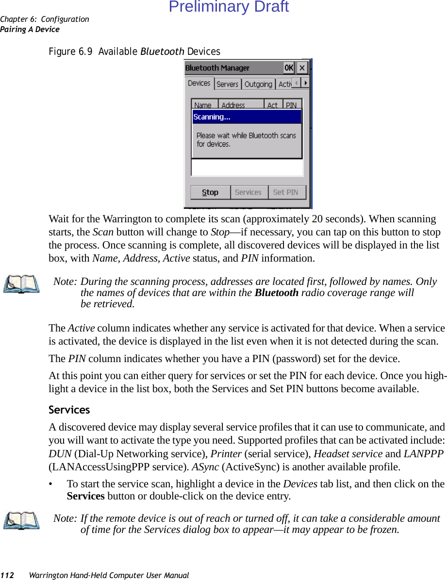
![Chapter 6: ConfigurationThe Servers Tab114 Warrington Hand-Held Computer User ManualIf the PIN has been validated, an asterisk (*) appears in the PIN column in the Devices list box, indicating that this device has a PIN set. Once a PIN is entered, it is saved in the registry.To remove the PIN:• Choose Set PIN, and press [ENTER].If the Warrington attempts to connect to a remote device that has Authentication enabled and does not have a required PIN set, an Authentication Request dialog box appears. • Enter the PIN, and tap on OK to connect the devices.6.6.2 The Servers TabThe Bluetooth connection is initiated from your Warrington to the remote device. Therefore the Warrington is called the ‘client’ and the remote is called the ‘server’. The Servers tab displays the server profiles that can be activated in your hand-held. There is currently one server profile available: Serial. • Tap on the checkbox to activate the server, and it will display the associated port name beside the server name. Once you activate a server profile, it is recommended that the Warrington be rebooted before you try to bond from a server. Note: You do not need to reboot if you are deactivating a server.Preliminary Draft](https://usermanual.wiki/Psion/PX750BT/User-Guide-963956-Page-126.png)
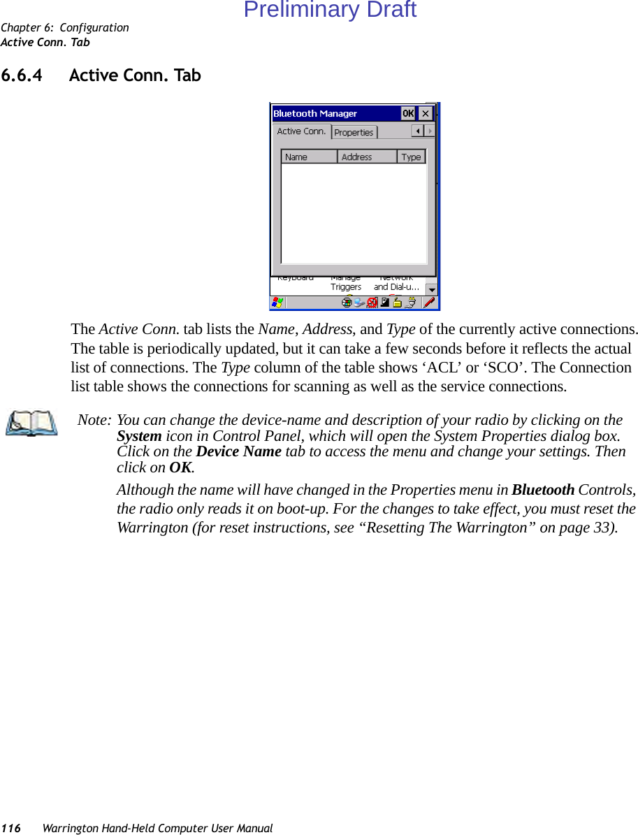
![Chapter 6: ConfigurationOutgoing TabWarrington Hand-Held Computer User Manual 1156.6.3 Outgoing TabOutgoing Port acts as a serial port that can be used to connect to a list of Bluetooth devices (one at a time), but you have the freedom to switch on-the-fly.The Outgoing Port checkbox allows you to create the Outgoing port. When the port is cre-ated, the Outgoing tab lists the port name.The Outgoing list dialog box displays a list of services marked as ‘Outgoing’. The * column indicates the currently selected service. You can tap on Unselect to reset the current selec-tion, or you can tap on Select to make a selection. The Remove button deletes the service from the outgoing list.The Prompt menu determines the behaviour of the pop-up Selection menu. Choosing Everytime causes the Selection menu to be displayed each time an outgoing port is created. If you choose Once, the menu is displayed only when a partner service is not selected.To display the Selection menu at any time:• Press [CTRL] [ALT] [F1], and switch the partner Bluetooth device. If a connection to a partner device already exists, the connection is dropped and another con-nection to the newly selected device is created instantly without disrupting the application that has opened the outgoing port.Note: To add a service to the Outgoing port, an active service must first be deactivated. Then you can choose the ‘Outgoing’ option from the Activation menu (highlight a service, right-click or press the [SPACE] bar to display the Activation menu).Preliminary Draft](https://usermanual.wiki/Psion/PX750BT/User-Guide-963956-Page-127.png)
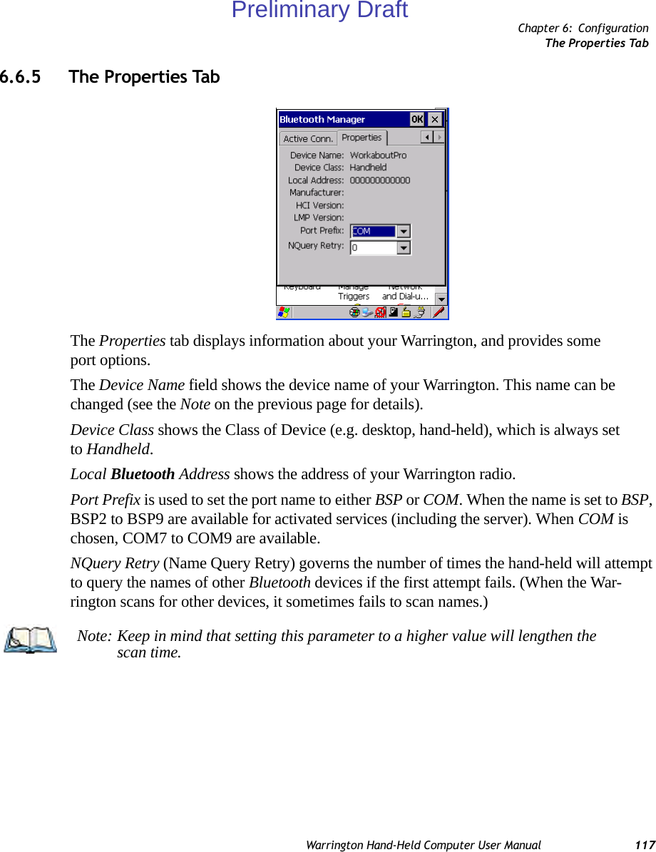
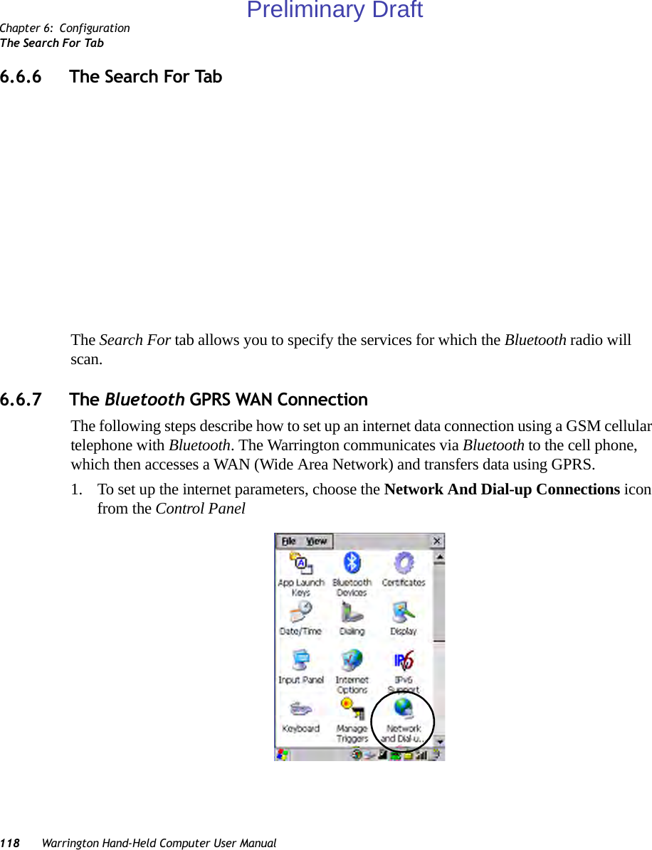
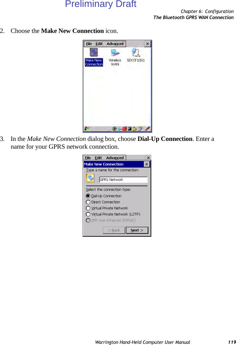
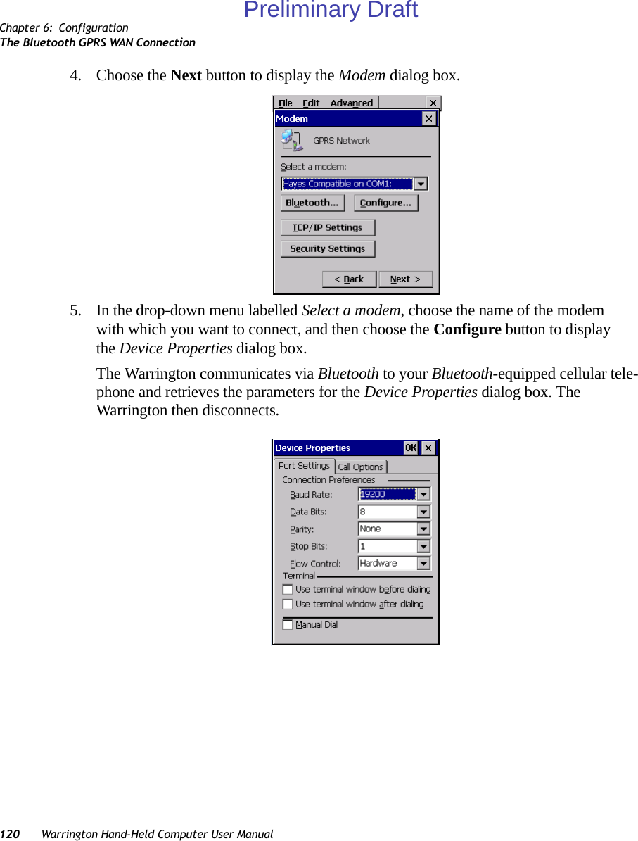
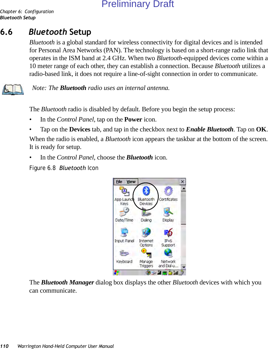
![Chapter 6: ConfigurationThe Bluetooth GPRS WAN ConnectionWarrington Hand-Held Computer User Manual 1216. Under the Call Options tab, turn off Cancel the call if not connected within, and press [ENTER] to save your changes.7. In the Modem dialog box, choose the Next button to display the Phone Number dialog box.The phone number you enter is network carrier dependent. Once you’ve specified all the necessary information, choose the Finish button.Preliminary Draft](https://usermanual.wiki/Psion/PX750BT/User-Guide-963956-Page-133.png)
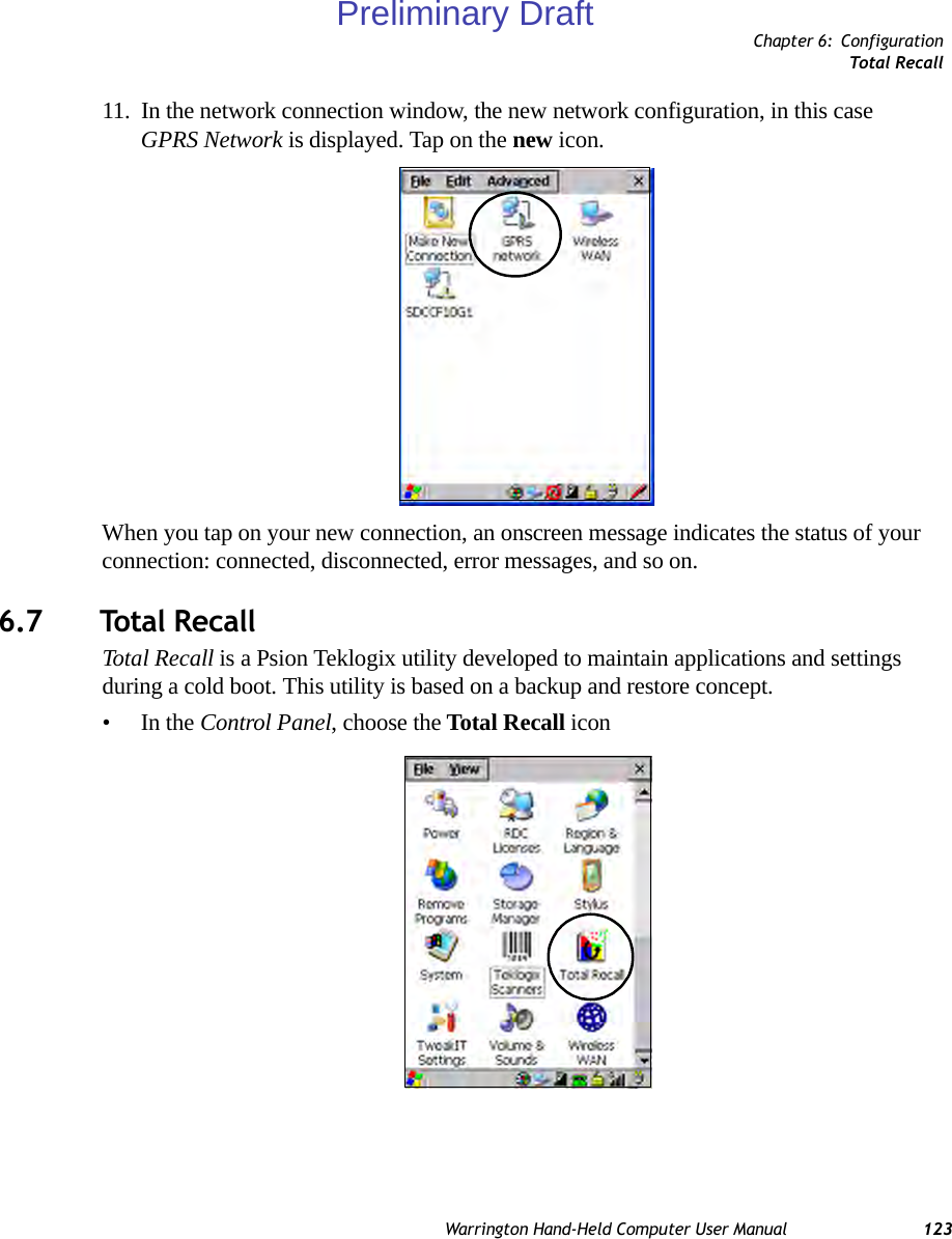
![Chapter 6: ConfigurationThe Bluetooth GPRS WAN Connection122 Warrington Hand-Held Computer User Manual8. In the Control Panel, choose the Dialing icon.9. The values in the Dialing Properties dialog box need to be edited according to your network carrier specifications.Once you’ve edited this dialog box to reflect your network carrier requirements, press [ENTER] to save your changes.10. At this point, you’ll need to return to the Control Panel, and choose the Network and Dial-up Connections icon.Preliminary Draft](https://usermanual.wiki/Psion/PX750BT/User-Guide-963956-Page-134.png)
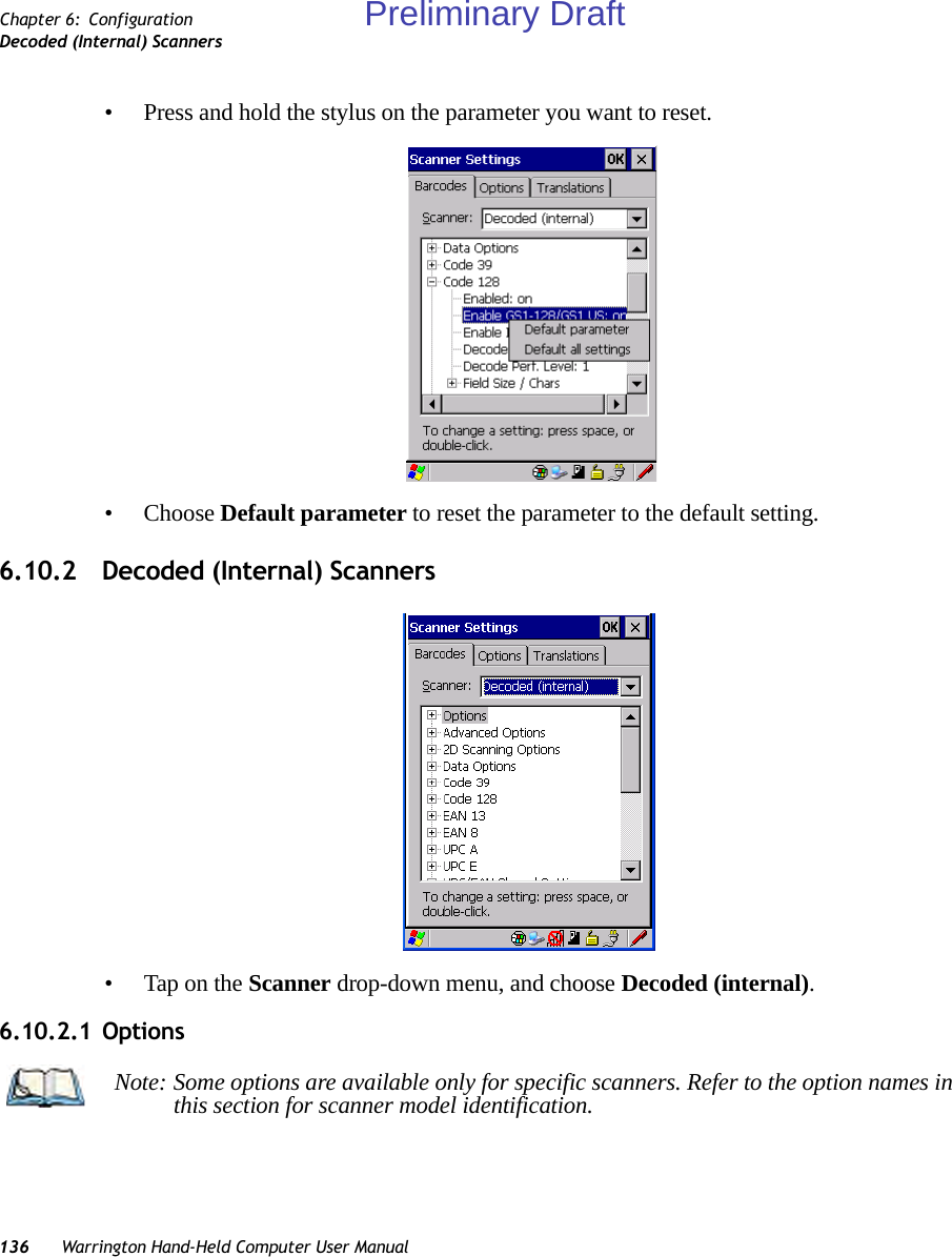
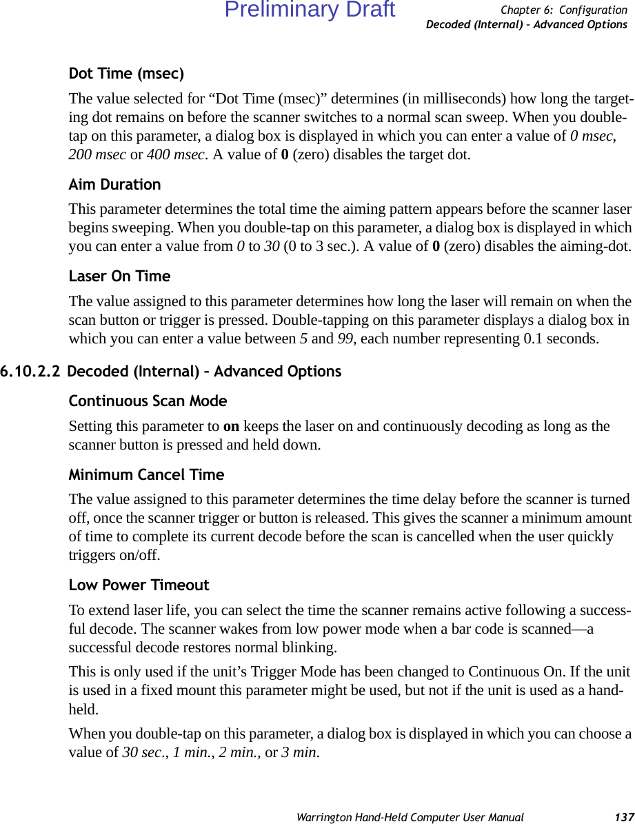
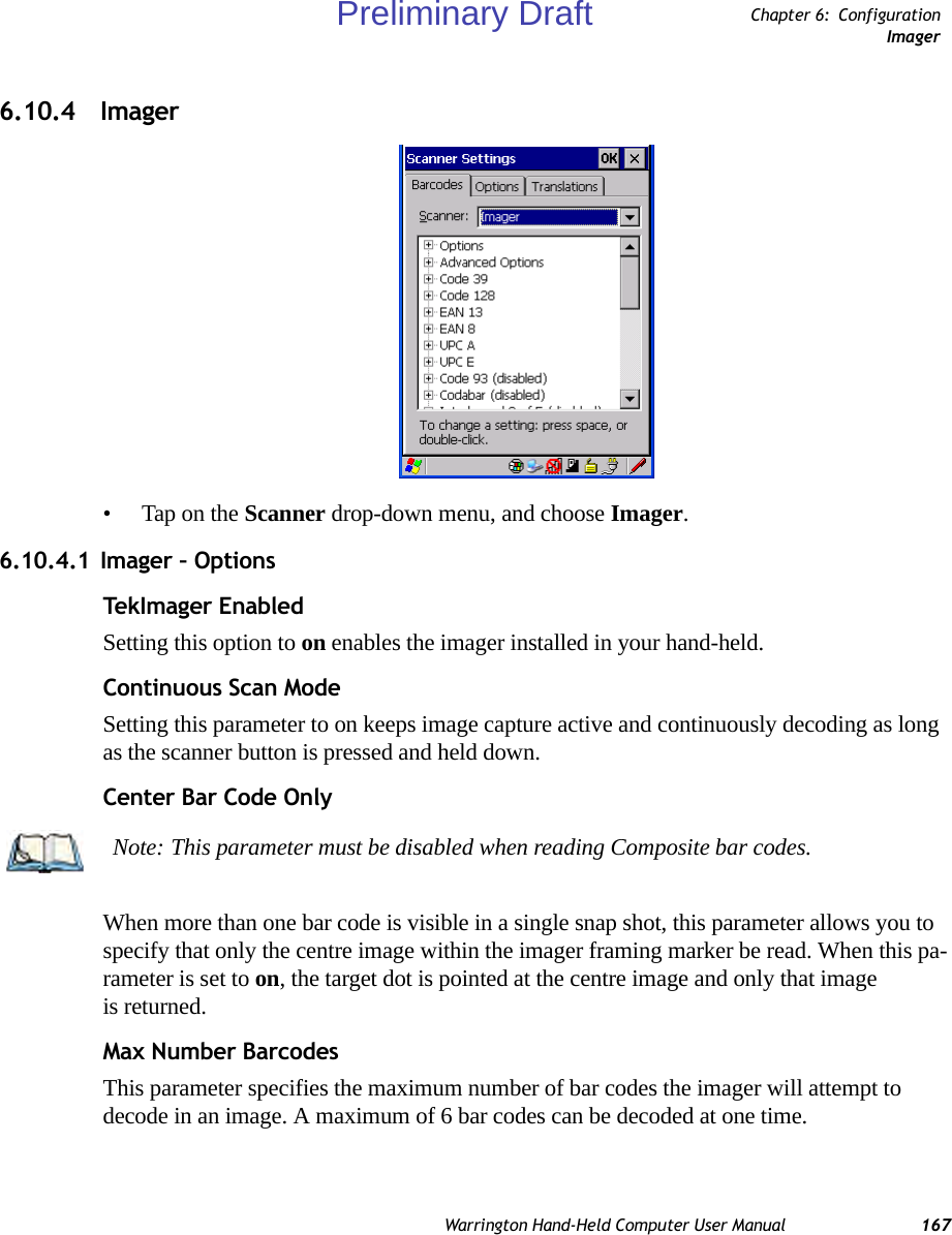
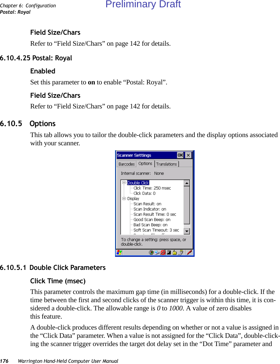
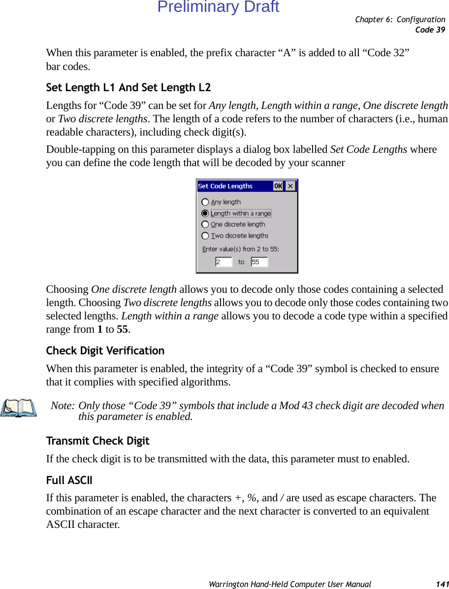
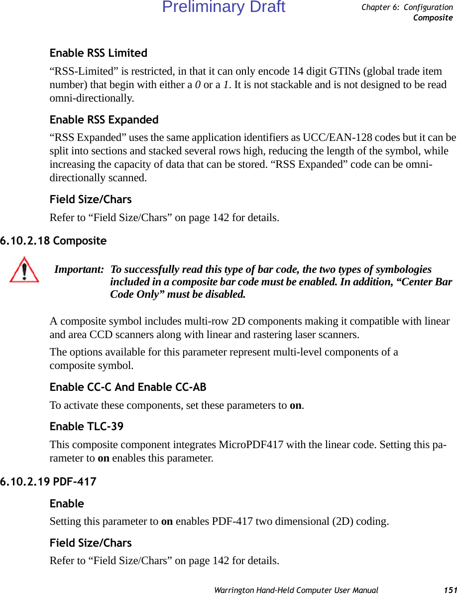
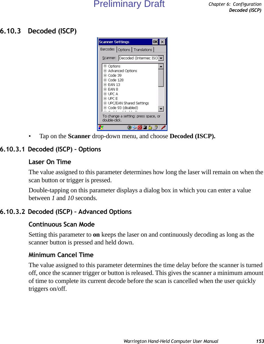
![Warrington Hand-Held Computer User Manual 139Chapter 6: ConfigurationDecoded (Internal) – 2D Scanning OptionsWhen this parameter is enabled, a bar code must be successfully scanned in both directions (forward and reverse) before being decoded.6.10.2.3 Decoded (Internal) – 2D Scanning OptionsScanning ModeWhen you double-tap on this parameter, a dialog box is displayed in which you can choose one of the following scanning modes: Smart Raster, Always Raster, Programmable Raster, Slab Pattern, Cyclone Pattern, or Semi-Omni Pattern.Raster Height And Raster Expand RateThese parameters determine the laser pattern’s height and rate of expansion.Double-tapping on this parameter displays a dialog box in which you can enter a value from 1 to 15.6.10.2.4 Decoded (Internal) Data OptionsTransmit Code ID CharA code ID character identifies the scanned bar code type. In addition to any single character prefix already selected, the code ID character is inserted between the prefix and the decoded symbol.When you double-tap on this parameter, a dialog box is displayed in which you can choose a transmit code: None, AIM, or Symbol.Scan Data FormatThis parameter allows you to change the scan data transmission format. Double-tapping on Scan Data Format displays the following options from which you can choose a data format: data (as-is), data [S1], data [S2], data [S1][S2], [P] data, [P] data [S1], [P] data [S2], and [P] data [S1][S2].Prefix [P], Suffix [S1] And Suffix [S2]A prefix and/or one or two suffixes may be appended to scan data for use in data editing.When you double-tap on these parameters, a dialog box is displayed in which you can enter a value from 0 to 255.Note: These parameters are only used when either Programmable Raster or Always Raster is assigned to the “2D Scanning Mode” parameter. “2D Raster Height” and “2D Raster Expand Rate” are intended for very specific applications and are usually not required for normal scanning purposes.Preliminary Draft](https://usermanual.wiki/Psion/PX750BT/User-Guide-963956-Page-151.png)
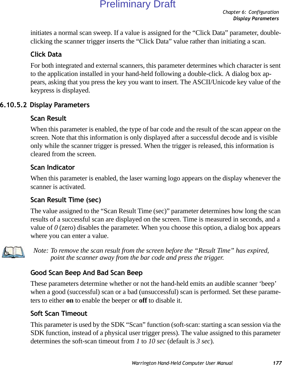
![144 Warrington Hand-Held Computer User ManualChapter 6: ConfigurationEAN 8Suffix CharThis character, if non-zero, is added after a successfully decoded bar code. Press the key you want to insert in the dialog box attached to this parameter. The ASCII/Unicode key value of the keypress is displayed.Strip LeadingThis parameter determines the number of characters that will be removed from the begin-ning of the bar code before the prefix character is added.Strip TrailingThe value entered in this parameter determines the number of characters that will be removed from the end of the bar code before the suffix character is added.6.10.2.8 EAN 8EnabledSet this parameter to on to enable “EAN 8”.EAN-8 Zero ExtendWhen this parameter is enabled, five leading zeros are added to decoded EAN-8 symbols, making them compatible in format to EAN-13 symbols. Disabling this parameter returns EAN-8 symbols to their normal format.Prefix/SuffixSee “Prefix/Suffix” on page 143.6.10.2.9 UPC AEnabledSet this parameter to on to enable “UPC A”.UPC-A, Check DigitIf you enable this parameter, the check digit is included with the decoded bar code data.UPC-A, PreambleWhen you double-tap on this parameter, a dialog box is displayed where you can choose one of three options for lead-in characters for UPC-A symbols transmitted to the host device: Note: The appended character is treated as any other keyboard character. For example, if [BKSP] is pressed, the usual action for that key is performed.Preliminary Draft](https://usermanual.wiki/Psion/PX750BT/User-Guide-963956-Page-156.png)
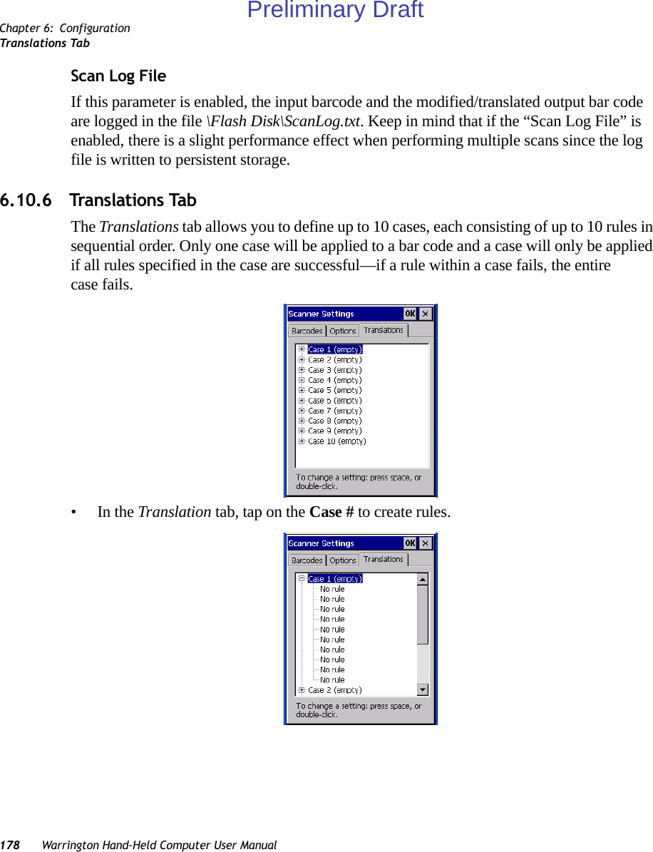
![152 Warrington Hand-Held Computer User ManualChapter 6: ConfigurationMicro PDF-4176.10.2.20 Micro PDF-417EnableSetting this parameter to on enables “Micro PDF-417” bar code scanning. Micro PDF-417 is a multi-row symbology that is useful for applications requiring greater area efficiency but lower data capacity than PDF-417.Code 128 EmulationWhen this parameter is enabled, the scanner transmits data from certain Micro PDF-417 symbols as if it was encoded in Code 128 symbols. If Code 128 Emulation is enabled, the following Micro PDF-417 symbols are transmitted with one of the following prefixes:]C1 if the first codeword is 903-907, 912, 914, 915]C2 if the first codeword is 908 or 909]C0 if the first codeword is 910 or 911If Code 128 Emulation is set to off, the Micro PDF-417 symbols are transmitted with one of the following prefixes:]L3 if the first codeword is 903-907, 912, 914, 915]L4 if the first codeword is 908 or 909]L5 if the first codeword is 910 or 911Field Size/CharsRefer to “Field Size/Chars” on page 142 for details.Preliminary Draft](https://usermanual.wiki/Psion/PX750BT/User-Guide-963956-Page-164.png)
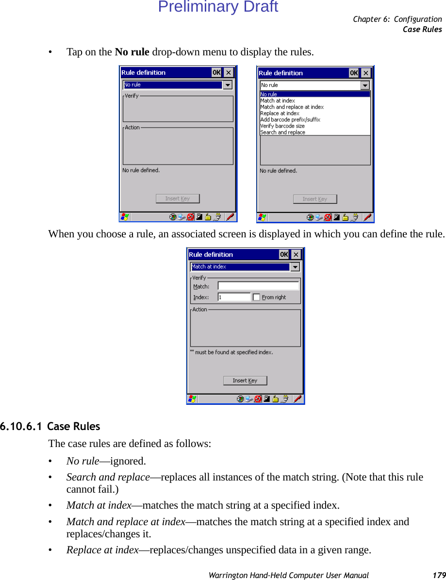
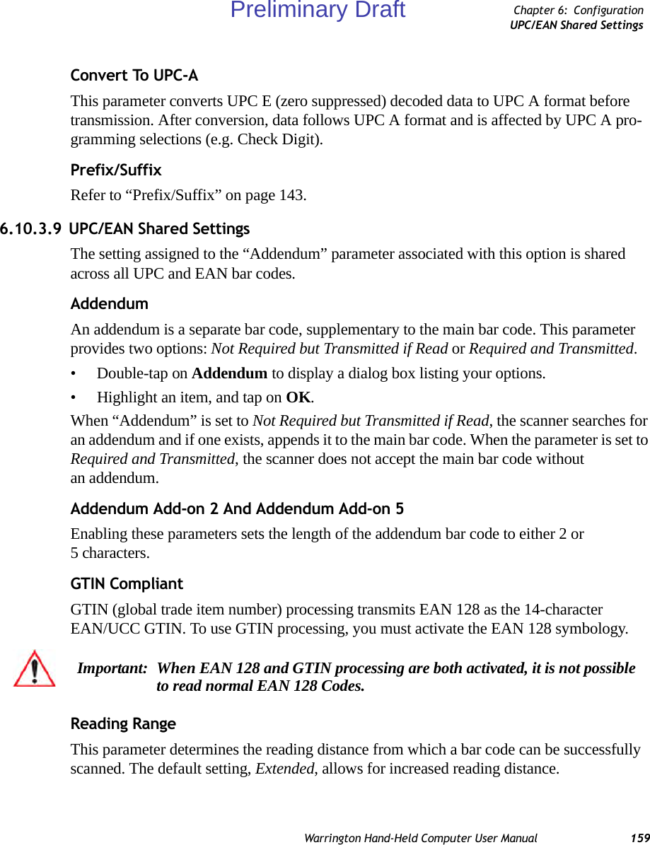
![Chapter 6: ConfigurationCode 128156 Warrington Hand-Held Computer User ManualGS1-128 Identifier“GS1-128 Identifier” allows the AIM ID " ]C1" for EAN 128 to be transmitted or removed. By default, this identifier is transmitted if EAN 128 is enabled.GTIN CompliantGTIN (global trade item number) processing transmits EAN 128 as the 14-character EAN/UCC GTIN. To use GTIN processing, you must activate the EAN 128 symbology.FNC1 Conversion“FNC1 Conversion” allows the FNC1 character to be converted to another character for ap-plications that cannot use the default <GS> Group Separator or hex (1d). Double-tapping on this option displays a dialog box listing the allowable range: 0 to 255. Enable ISBT 128 To successfully scan this type of bar code (International Society of Blood Transfusion), this option must be set to on. If you enable this type of bar code, Code 128/EAN 128 is deacti-vated to avoid any confusion.ISBT Concat TransmitThe codes are not concatenated by default. You need to choose one of the options provided for this parameter to send concatenated code. Choosing Only Concatenated Codes transmits only concatenated codes—single codes will not be transmitted. Choosing Concatenated or Single transmits single codes or concatenated codes. If only one code of a pair is read, that code will be transmitted as a single code. If both codes in a pair are detected, they will be concatenated provided that “ISBT Concat Any Pair” (see below) is enabled.ISBT Concat Any PairEnabling this parameter causes all code pairs that can be, to be concatenated even if they do not comply with Section 4.1 of the “ISBT 128 Bar Code Symbology and Application Speci-fication for Labeling of Whole Blood and Blood Components” (June 2000, Version 1.2.1).Reading RangeDetermines the reading distance from which a bar code can be successfully scanned. The default setting, Extended, allows for increased reading distance. Important: When EAN 128 and GTIN processing are both activated, it is not possible to read normal EAN 128 Codes. Preliminary Draft](https://usermanual.wiki/Psion/PX750BT/User-Guide-963956-Page-168.png)
![166 Warrington Hand-Held Computer User ManualChapter 6: ConfigurationCodablockIf Code 128 Emulation is enabled, the following Micro PDF-417 symbols are transmitted with one of the following prefixes:]C1 if the first codeword is 903-907, 912, 914, 915]C2 if the first codeword is 908 or 909]C0 if the first codeword is 910 or 911If Code 128 Emulation is set to off, the Micro PDF-417 symbols are transmitted with one of the following prefixes:]L3 if the first codeword is 903-907, 912, 914, 915]L4 if the first codeword is 908 or 909]L5 if the first codeword is 910 or 911Field Size/CharsRefer to “Field Size/Chars” on page 142 for details.6.10.3.21CodablockEnable Codablock ASet this parameter to on to enable “Codablock type A”.Enable Codablock FSet this parameter to on to enable “Codablock type F”.Field Size/CharsRefer to “Field Size/Chars” on page 142 for details.Preliminary Draft](https://usermanual.wiki/Psion/PX750BT/User-Guide-963956-Page-178.png)