Psion RA1001 UHF RADIO TRANSCEIVER MODULE User Manual RA1001
Psion Inc UHF RADIO TRANSCEIVER MODULE RA1001
UserManual.wiki
>
Psion
>
RA1001 User Manual
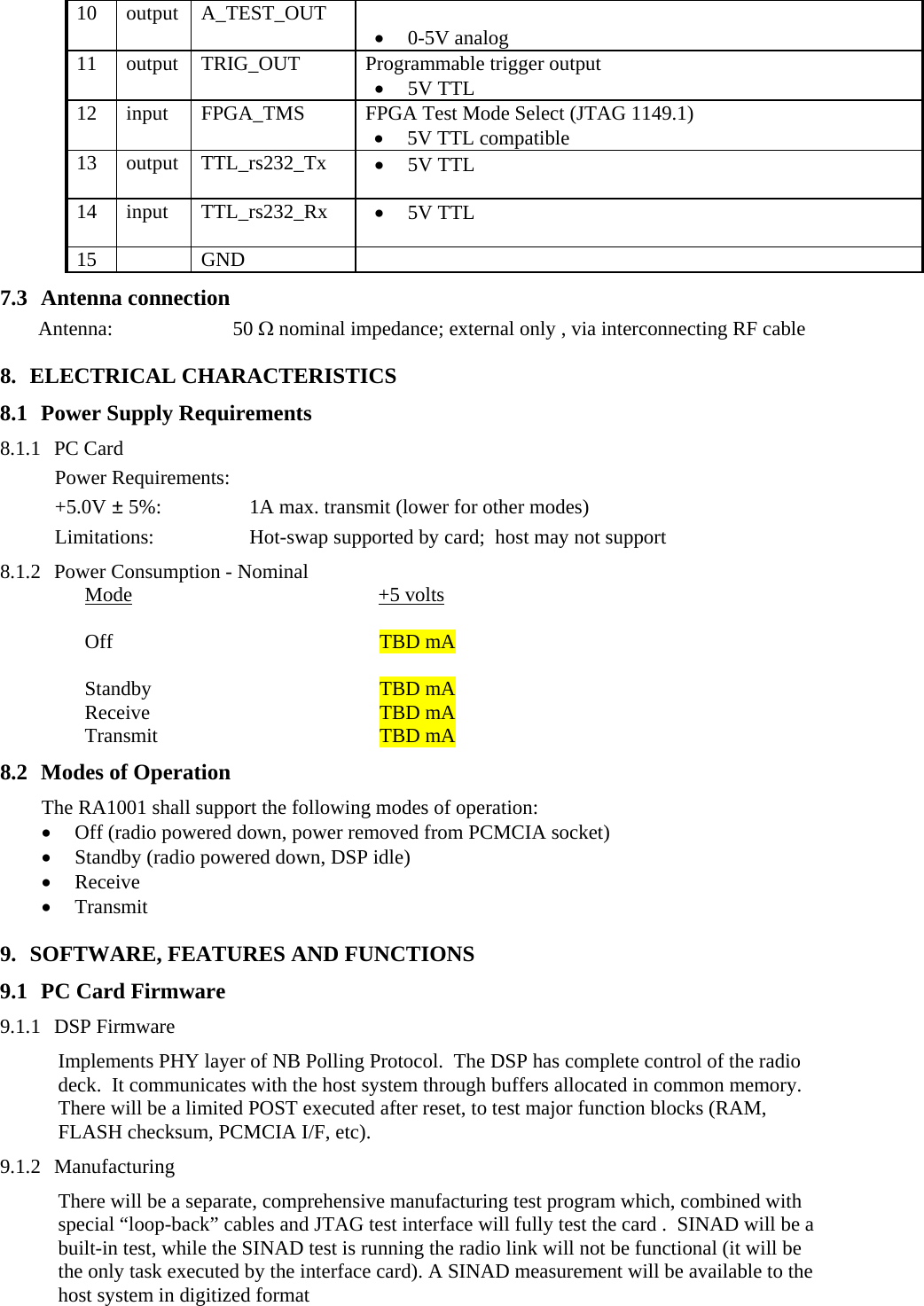
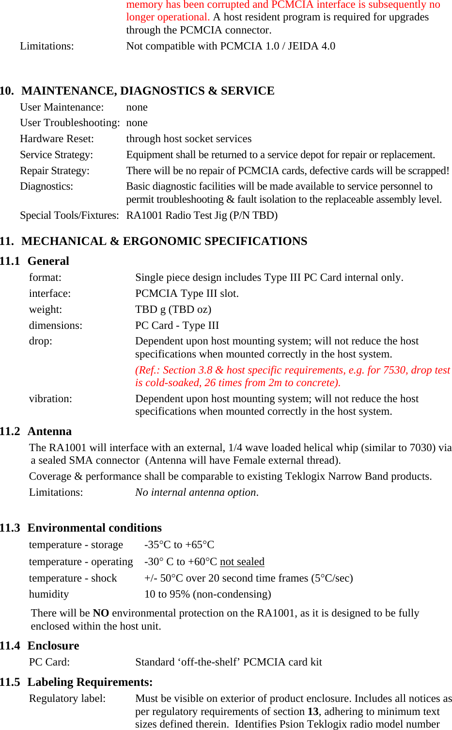
USERS MANUAL
Navigation menu
Upload a User Manual
Namespaces
Wiki Guide
HTML
PDF
Info
Views
User Manual
Discussion / Help
Navigation
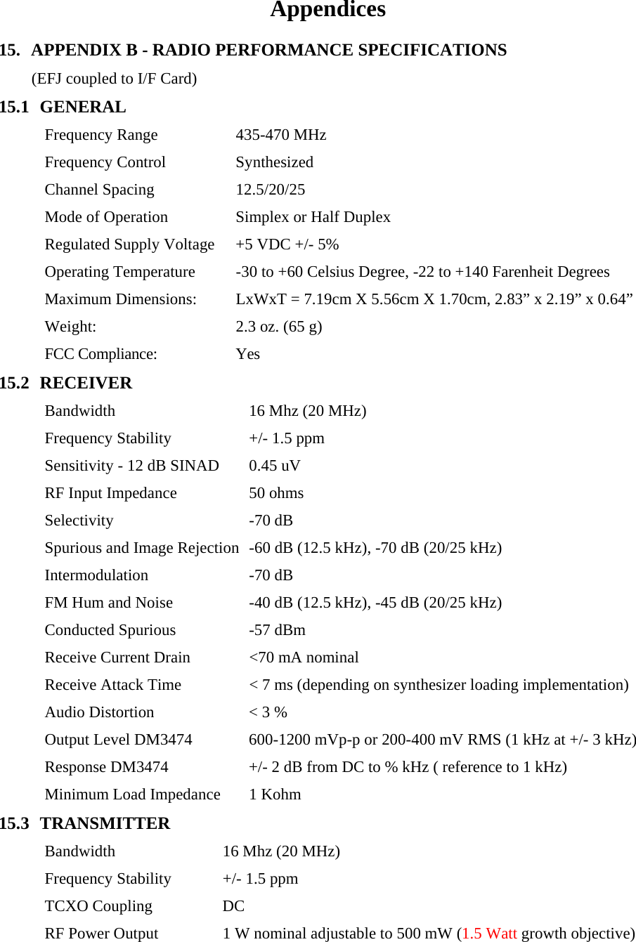
![Management V1.2) • Teklogix proprietary Cell Base module for 9150 access point. 3.5 RF Connectivity Network access: Teklogix 9150 Access Point & Base Station, or 9130/9140 base station, combined with Teklogix 93xx/94xx/95xx Series of Network Controllers RF protocol: Teklogix NB Polling Protocol (Cellular mode). [Compatible with all current 32-bit 4800/9600/19.2 Teklogix systems.] Roaming: transparent via 9130, 9140 and 9150 Access Point Cell Base modes Frequency range: 403 - 512 MHz Data Rate & Mode: 2 level FM (proprietary FSK) 4800 bps, 9600 bps (effective peak rate) 4 level FM: (proprietary FSK) 4800, 9600 bps, 19.2 Kbps RF Power: Factory set, 0.5 to 1 Watt (1.5 Watt growth objective) Channel Spacing: 12.5, 20, 25 KHz (6.25KHz required from FCC, 1 Jan.’05). Sensitivity: -112 dBm nominal @ 10-2 BER - Dependent upon the host computer EMC characteristics, qualified in various Teklogix terminals (& Teklogix 9150 Access Point if required). 3.6 PC Card Accessible Control, Configuration and Diagnostics The following control and diagnostic features can be accessed by the host system through the PC Card interface: 3.6.1 Radio Alignment • transmit frequency channel centering • transmit power level (fine adjustment only) • transmit deviation • receiver squelch level or equivalent Access to these settings shall be restricted through the use of a password or other secure feature to avoid unauthorized adjustment. This security feature will be implemented by the driver software. 3.6.2 Radio Control and Support Functions for FI&T, Approvals and EMC Testing (i.e. RTEST features) • channel(frequency) selection • transmit long • transmit with no modulation • transmit test • receive test • carrier detect disable • transmit time-out (adjustable timer) • site survey mode See the section describing radio modes for a more complete description. 3.7 Modes of Operation The RA1001 shall support the following power saving modes of operation: • Off • Suspend: (radio deck powered down, DSP processor idle, control and interface circuitry active only) • APM enabled (Standby, Receive, Transmit as appropriate) 3.8 Features Not Supported The following features are not offered in this product.](https://usermanual.wiki/Psion/RA1001/User-Guide-499401-Page-7.png)

![9.2 Host Software (Ref.: RTEST features) 9.2.1 Radio Protocol Drivers shall be developed supporting the following features: • compatible with Teklogix NB Polling Protocol in both Cellular and non-Cellular modes • transparent roaming and power saving modes (terminals only) • RMAN API interface supported by the TekTerm application (terminals only) • radio protocol diagnostic information (viewable via TekTerm for terminals and via BCM command line for the 9150) 9.2.2 Radio Tests Software shall be developed that will allow the user to perform the following radio tests: • channel (frequency) selection • transmit long • transmit without modulation • transmit test • receive test • carrier detect disable The radio test software will display appropriate statistics for each test (eq.BER for receive test). 9.2.3 Configuration and Tuning Software shall be developed that will allow the user to configure all necessary radio settings such as data rate, modulation type and operating frequency. The software will also allow the user to perform the following radio tuning operations: • fine adjustment of transmit power • transmit center frequency adjust • transmit modulation adjust • transmit modulation balance adjust Access to restricted radio configuration settings will be password protected. 9.2.4 Site Survey (terminals only) A site survey application shall be developed for the RA1001 that will perform in a similar manner to the site survey application available on the 7030 terminal. 9.2.5 Power Management (terminals only) The RA1001 radio drivers will set the operating mode of the RA1001 radio to properly correspond with the terminal modes of operation which include Full On, APM Enabled, APM Standby, APM Suspend, and Off. The will be no support for the APM mode “Full-On”, the radio interface card will always enter the lowest power possible. 9.2.6 RA1001 FLASH Upgrade Software shall be developed to support upgrading the RA1001 FLASH through the PCMCIA host connection, for in-system upgrade. For depot upgrade, a JTAG programming interface will be supported. Only firmware which is Regulatory Agency approved can be loaded on customer terminals. 9.3 Supplied Drivers Support Services Socket Services: TBD Radio Parameters: TBD [Note parameters affecting regulatory approvals must be permanently configured at the factory with no facility for a user application to modify them.] FLASH Upgrade: Programmable through PCMCIA host connector for field upgrade, or through JTAG test connector for manufacture or in the event that flash](https://usermanual.wiki/Psion/RA1001/User-Guide-499401-Page-14.png)
![(RA1001) and part number specific to the radio configuration. 12. APPROVAL REQUIREMENTS 12.1 Radio ETSI ETS 300-113 EN 300-220-1 FCC FCC Part 90 Intentional Radiator (card and radio) DOC ICAN RSS-210 Intentional Radiators. ICAN RSS-119 Intentional Radiators EC EC Each model requires separate approvals in each target country. ROW As required on a per country basis. 12.2 EMC USA FCC Part 15, Subpart B, Class B – Unintentional Radiator, Canada ICES-003 / CSA C108.8-M1983 Unintentional Radiators - Class B (Note: not required if FCC part 15, subpart B is tested) EC ETS 300 683 ETS 300 279 These standards will provide compliance with EMC Directive 89/336/EEC, Class B (CE Mark Compliance) Rest of World As required on per country basis. 12.3 SAFETY EC Low Voltage Directive 73/23/EEC, but no voltage limit applying. 13. MANUFACTURING SPECIFICATIONS 13.1 General The design of this product and all accessories will be compliant with Manufacturing strategies, requirements and processes as defined in the Manufacturing Plan. The final product and sub-assemblies are designed to be tested using current methods and equipment (whether at Teklogix or a vendor), wherever feasible [custom test fixtures & test software is of course required.]. All components which may be subject to significant supply risks will have alternates sourced where feasible. 13.2 Production Assembly 13.2.1 Assembly Processes The RA1001 PC Card will be fully assembled, tested and sealed by the subcontractor prior to shipment to Teklogix. 13.2.2 Production Test Specifications TBD 14. FUTURE OPTIONS & UPGRADES 14.1 Operating Systems & User Interfaces As required (supported by Change of Scope). 14.2 Voice Mode Two voice modes could be supported in future releases, the first would support digitized](https://usermanual.wiki/Psion/RA1001/User-Guide-499401-Page-16.png)