Public Wireless CM150D01 Single Band fiber optically fed 850MHz outdoor repeater User Manual Revised
Public Wireless, Inc Single Band fiber optically fed 850MHz outdoor repeater Revised
UserManual.wiki
>
Public Wireless
>
CM150D01 User Manual
Revised User Manual
Navigation menu
Upload a User Manual
Namespaces
Wiki Guide
HTML
PDF
Info
Views
User Manual
Discussion / Help
Navigation
![5 / 17 4. Mechanical Specifications 4.1. CM150D-01 DU 4.1.1. Mechanical Design [FRONT] 4.1.2. Mechanical specification No Items Specifications 1 Exterior view 1. Shelf attachable type to both INDOOR and OPEN RACK 2. W 19” ³ H 3.5” ³ D 15.75” 3. Weight: 14.1 lbs 2 Material Aluminum (AL5052, AL6063) is mainly used for protection from corrosion by external environments. 3 Connector Type 1. Optic I/O: FC/APC at rear 2. RF I/O: SMA Female at rear 3. Monitor port: SMA Female at front](https://usermanual.wiki/Public-Wireless/CM150D01/User-Guide-1233338-Page-5.png)
![6 / 17 4 Power Input 1.Power: 110-120Vac, 60Hz 2.Connector: IN-NO3BEH 5 Ground 14SQ 2Hole ground pipe (right side of shelf) and M4 “O” rug ground (rear side of shelf) 6 Communication Port 9P D-SUB (GUI), front side 4.1.3. Descriptions of CM150D-01 DU [Downlink Path] The signal from GSM or WCDMA BTS is fed to the RF input port of DU. It becomes the input signal to the optic module to be transmitted to RU. [Uplink Path] The optical signal from RU (GSM or WCDMA) is converted into RF and becomes the input signal to the BTS of GSM or WCDMA. 4.2. CM150D-01 RU 4.2.1. Mechanical Design](https://usermanual.wiki/Public-Wireless/CM150D01/User-Guide-1233338-Page-6.png)
![7 / 17 4.2.2. Mechanical Specification No Item Description 1 Dimension & Weight Dimension: W 25” ³ H 12” ³ D 11” Weight: 65 lbs 2 Method of Cooling Natural convection (Heat-sink) 4 Optic I/O 1. Single port 2. Connector type: FC/APC 5 ANT PORT 1. Single port 2. Connector Type: N Type 6 Power Input 1. 65 – 90 VAC Quasi Square Wave 2. Single port 3. Connector Type : F Connector 8 Waterproof condition IP67 compliant 4.2.3. Description of CM150D-01 RU [Downlink path] The optical signal is converted into RF and linearly amplified at HPA, passed through the Duplexer, and finally transmitted through an external antenna. [Uplink Path] GSM and WCDMA signals incoming from an antenna are first passed by the Duplexer and then transmitted to DU through the optic module.](https://usermanual.wiki/Public-Wireless/CM150D01/User-Guide-1233338-Page-7.png)

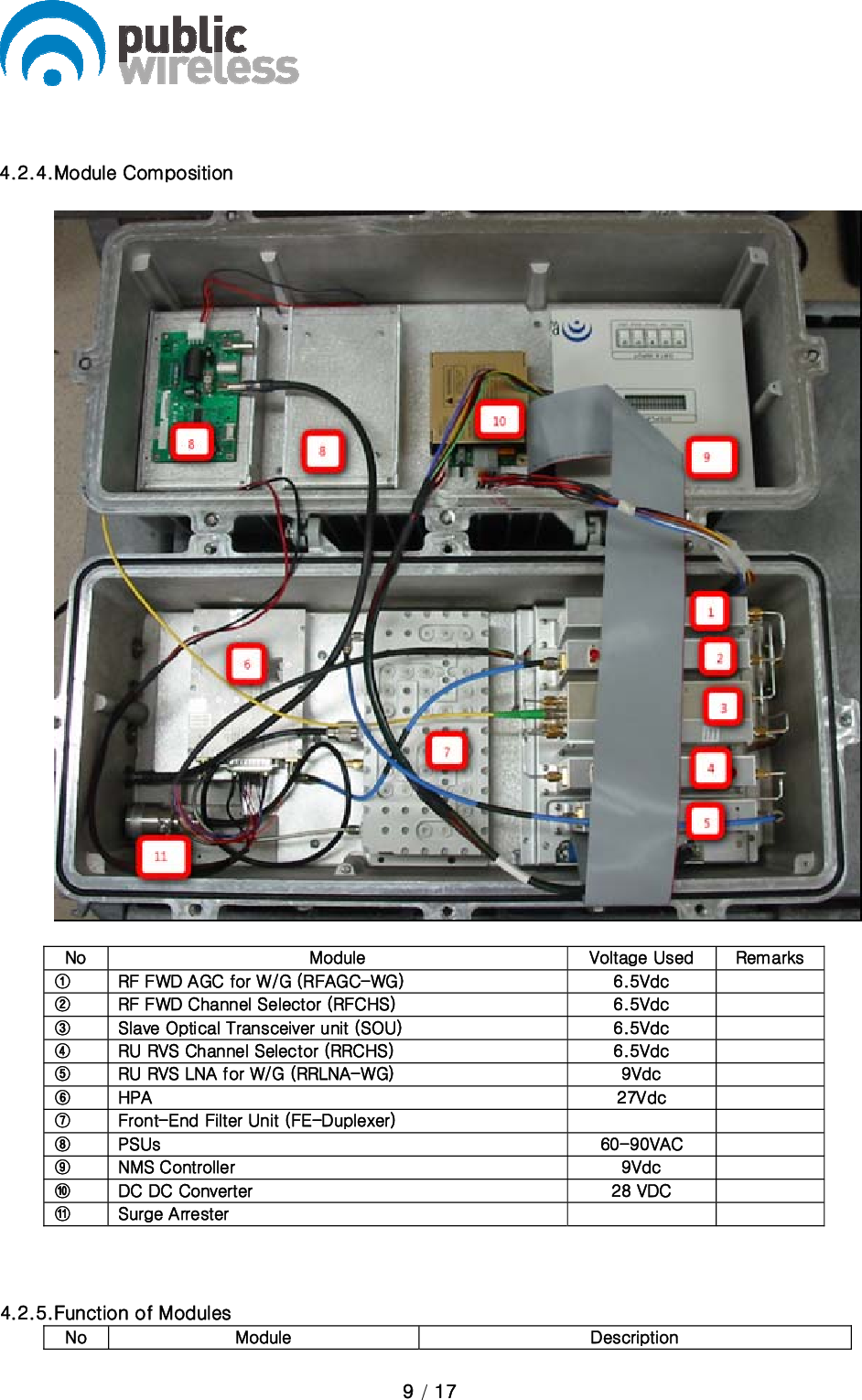
![10 / 17 1 [RFAGC-WG] Divides RF signal (GSM and WCDMA) and modem signal 2 [RFCHS] Controls the level of FWD output signal, select the downlink band and perform the ALC function. The module output is sent to HPA. 3 [SOU] Converts E/O (or O/E) of FWD and RVS signals. Wavelength: TX 1550[nm], RX 1310[nm] 4 [FSK Modem] Data modem for RU and DU communication RU → DU frequency: 340MHz DU → RU frequency: 360MHz 5 [RRCOM-WG] Combines RF and data signal into a signal and provides the combined signal to optical module in order to convert E/O. 6 [RRCHS] Amplifies RVS signal, select the filtering band and control the uplink path gain of RU. 7 [RRLNA-WG] A low noise amplifier module for GSM and WCDMA. It has 20dB coupling gain compared to the output of the module. And includes built-in local oscillator to check uplink path gain. 8 [HPA] 8Watt High power amplifier that amplifies the signal from the RFCHS.](https://usermanual.wiki/Public-Wireless/CM150D01/User-Guide-1233338-Page-10.png)
![11 / 17 9 [FE-Duplexer] Front end duplexer that passes through desired frequency bands. 11 [NMS] Monitors/controls the status, and the configurable items and the modules of RU. 12 [Interface BD] Provides DC current to modules which are connected to interface B’D and supports a connection port to communicate with NMS B’D.](https://usermanual.wiki/Public-Wireless/CM150D01/User-Guide-1233338-Page-11.png)