Public Wireless CM150D01 Single Band fiber optically fed 850MHz outdoor repeater User Manual Revised
Public Wireless, Inc Single Band fiber optically fed 850MHz outdoor repeater Revised
Revised User Manual

Fiber DAS Operating Manual
Public Wireless
2009. 12

2 / 17
Contents
1.Introduction................................................................................................. 3
1.1.General............................................................................................. 3
2.Network configuration of system........................................................................ 3
2.1.Network configuration............................................................................ 3
3.System Specifications .................................................................................... 3
3.1.System specifications............................................................................ 3
3.1.1.Frequency allocation .................................................................... 3
3.1.2.System Specifications .................................................................. 3
4.Mechanical Specifications ............................................................................... 3
4.1.CM150D-01 DU .................................................................................. 3
4.1.1.Mechanical Design ...................................................................... 3
4.1.2.Mechanical specification ............................................................... 3
4.1.3.Descriptions of CM150D-01 DU ...................................................... 3
4.2.CM150D-01 RU .................................................................................. 3
4.2.1.Mechanical Design ...................................................................... 3
4.2.2.Mechanical Specification ............................................................... 3
4.2.3.Description of CM150D-01 RU ........................................................ 3
4.2.4.Module Composition .................................................................... 3
4.2.5.Function of Modules..................................................................... 3
5.Administration Program (RptMan) ...................................................................... 3
5.1.System Requirement ............................................................................. 3
5.2.Screen.............................................................................................. 3
5.3.Status Display..................................................................................... 3
5.4.Control Policy ..................................................................................... 3
5.5.Menu ............................................................................................... 3
5.6.Toolbar............................................................................................. 3
5.7.Program operation ............................................................................... 3
5.7.1.Initiating communication................................................................3
5.7.2.Disconnection ............................................................................ 3
5.7.3.CM150D-01 RU Status Retrieval and Control ....................................... 3

3 / 17
FCC WARNING
This equipment generates or uses radio frequency energy. Changes or modifications to this
equipment may cause harmful interference unless the modifications are expressly approved in the
instruction manual. The user could lose the authority to operate this equipment if an unauthorized
change or modification is made.
4 / 17
1. Introduction
1.1. General
The Public Wireless Fiber Fed DAS solution allows deployment of cellular coverage in areas
underserved by the current cellular network.
2. Network configuration of system
2.1. Network configuration
The Public Wireless Fiber Fed DAS solution conforms to the traditional analog fiber transport
DAS architecture, with central hub units (DUs) feeding RF signals over fiber links to CM150D
remote units (RUs).
z System configuration
System Connection: Single mode fiber optic cable between DU and RU
Optic Wavelength: 1310nm for FWD, 1550nm for RVS
3. System Specifications
3.1. System specifications
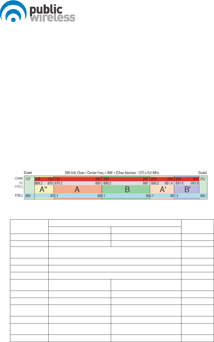
3.1.1. Frequency allocation
3.1.2. System Specifications
Specification
Item WCDMA GSM Remarks
Downlink (Tx) 870 - 890 MHz 869 - 891.4 MHz cf. 3.2.1
Uplink (Rx) 825 – 845 MHz 824 – 846.4
Frequency
Stability 0.01PPM
System Delay 5usec max.
Tx-Rx Isolation 100dB min.
Impedance 50 Ohm
RU DL Output
Power 37 dBm composite 37 dBm composite
System Gain 72dB 60dB
FWD Spurious 3GPP, FCC compliant 3GPP, FCC compliant
RVS Noise
Figure 7dB max. 7dB max.
EVM or Rho 12.5%
Gain Control
Range RU: 20dB by 1dB Step RU: 20dB by 1dB Step
VSWR 1.5: 1 max. 1.5: 1 max.

5 / 17
4. Mechanical Specifications
4.1. CM150D-01 DU
4.1.1. Mechanical Design
[FRONT]
4.1.2. Mechanical specification
No Items Specifications
1 Exterior view 1. Shelf attachable type to both INDOOR and OPEN RACK
2. W 19” ³ H 3.5” ³ D 15.75”
3. Weight: 14.1 lbs
2 Material Aluminum (AL5052, AL6063) is mainly used for protection from
corrosion by external environments.
3 Connector Type 1. Optic I/O: FC/APC at rear
2. RF I/O: SMA Female at rear
3. Monitor port: SMA Female at front
6 / 17
4 Power Input 1.Power: 110-120Vac, 60Hz
2.Connector: IN-NO3BEH
5 Ground 14SQ 2Hole ground pipe (right side of shelf) and M4 “O” rug
ground (rear side of shelf)
6 Communication Port 9P D-SUB (GUI), front side
4.1.3. Descriptions of CM150D-01 DU
[Downlink Path]
The signal from GSM or WCDMA BTS is fed to the RF input port of DU. It becomes the
input signal to the optic module to be transmitted to RU.
[Uplink Path]
The optical signal from RU (GSM or WCDMA) is converted into RF and becomes the input
signal to the BTS of GSM or WCDMA.
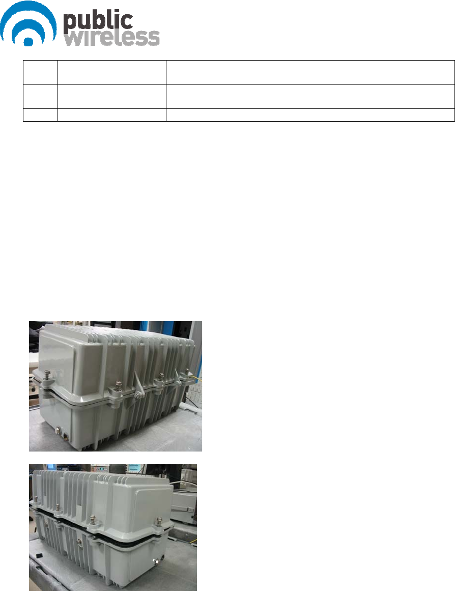
4.2. CM150D-01 RU
4.2.1. Mechanical Design
7 / 17
4.2.2. Mechanical Specification
No Item Description
1 Dimension & Weight Dimension: W 25” ³ H 12” ³ D 11”
Weight: 65 lbs
2 Method of Cooling Natural convection (Heat-sink)
4 Optic I/O 1. Single port
2. Connector type: FC/APC
5 ANT PORT 1. Single port
2. Connector Type: N Type
6 Power Input
1. 65 – 90 VAC Quasi Square Wave
2. Single port
3. Connector Type : F Connector
8 Waterproof condition IP67 compliant
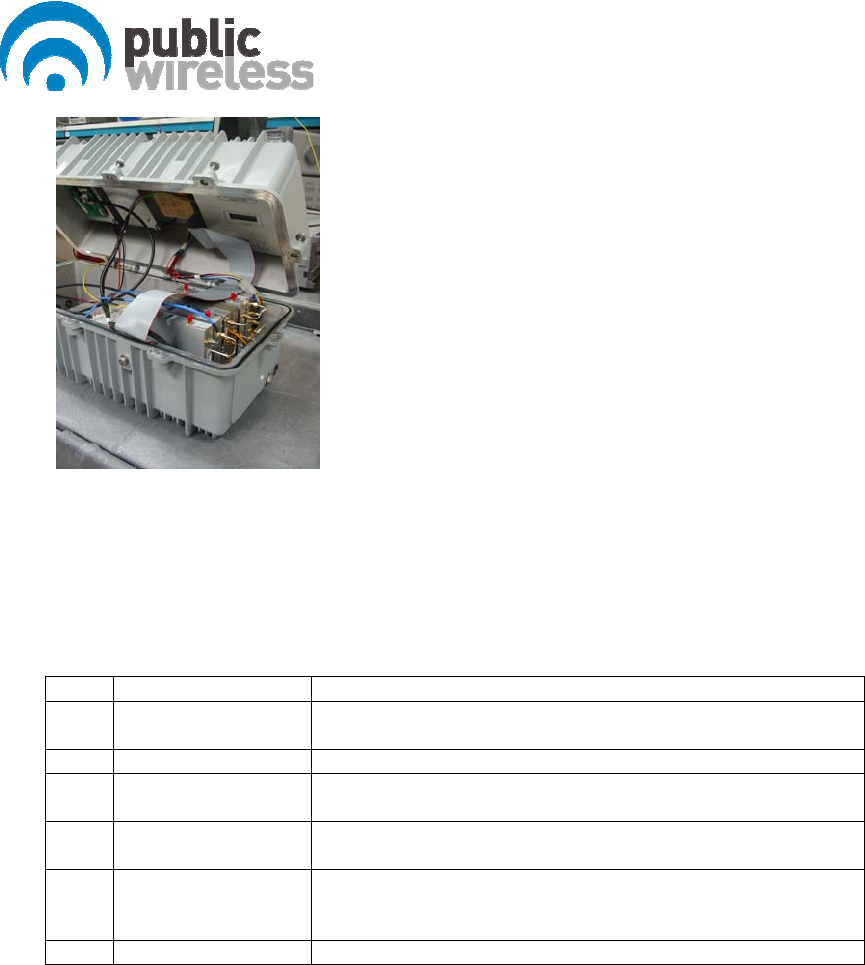
4.2.3. Description of CM150D-01 RU
[Downlink path]
The optical signal is converted into RF and linearly amplified at HPA, passed through the
Duplexer, and finally transmitted through an external antenna.
[Uplink Path]
GSM and WCDMA signals incoming from an antenna are first passed by the Duplexer and
then transmitted to DU through the optic module.

8 / 17
9 / 17
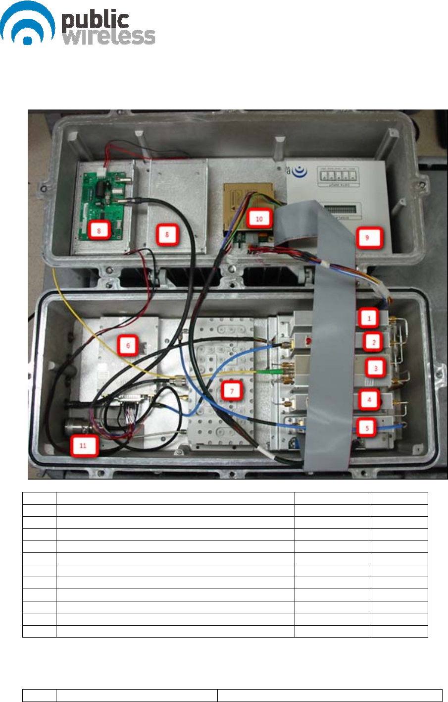
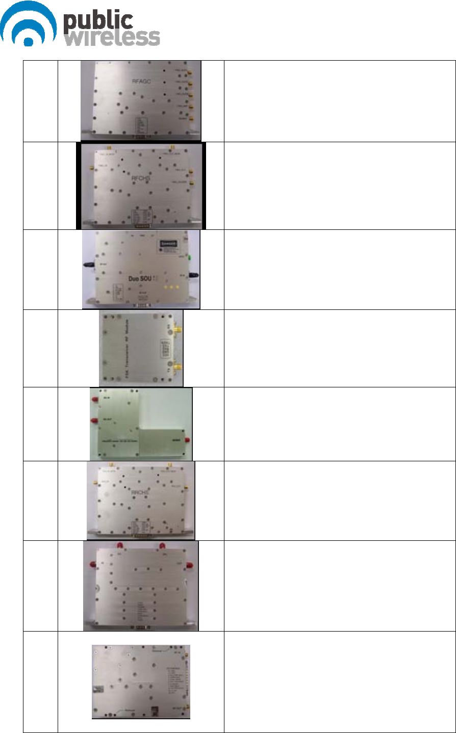
4.2.4. Module Composition
No Module Voltage Used Remarks
① RF FWD AGC for W/G (RFAGC-WG) 6.5Vdc
② RF FWD Channel Selector (RFCHS) 6.5Vdc
③ Slave Optical Transceiver unit (SOU) 6.5Vdc
④ RU RVS Channel Selector (RRCHS) 6.5Vdc
⑤ RU RVS LNA for W/G (RRLNA-WG) 9Vdc
⑥ HPA 27Vdc
⑦ Front-End Filter Unit (FE-Duplexer)
⑧ PSUs 60-90VAC
⑨ NMS Controller 9Vdc
⑩ DC DC Converter 28 VDC
⑪ Surge Arrester
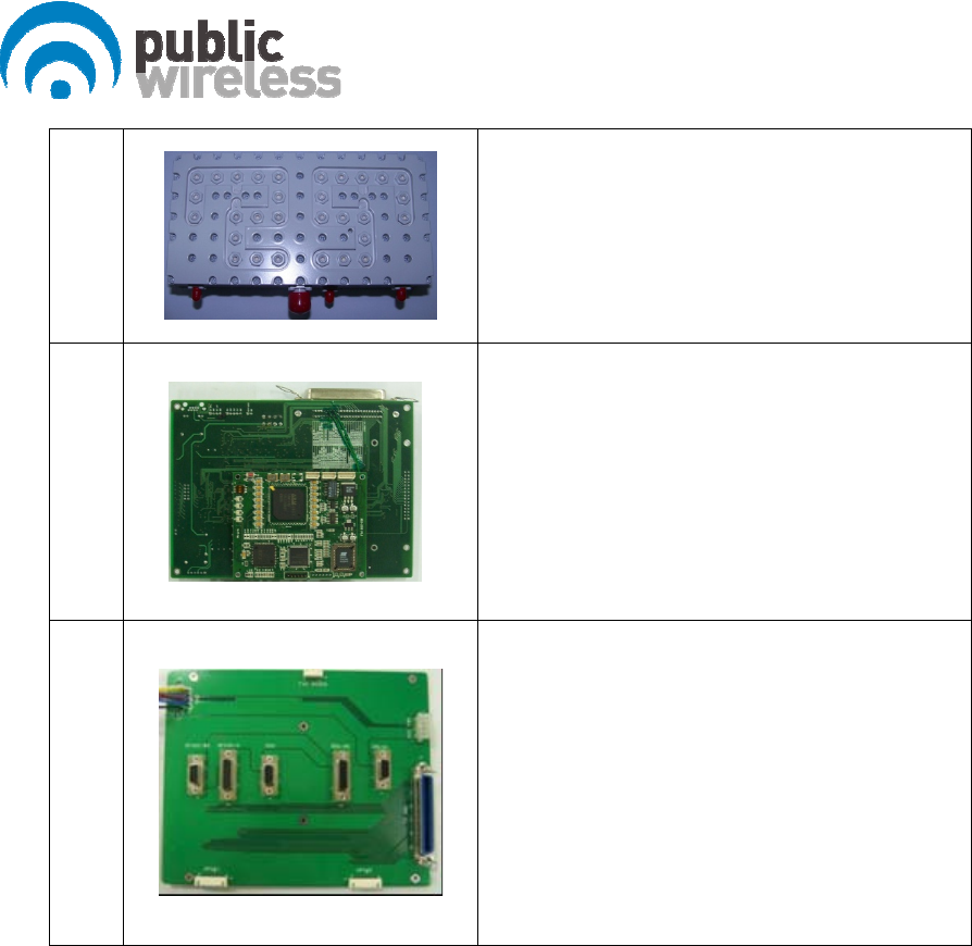
4.2.5. Function of Modules
No Module Description
10 / 17
1
[RFAGC-WG]
Divides RF signal (GSM and WCDMA) and modem
signal
2
[RFCHS]
Controls the level of FWD output signal, select the
downlink band and perform the ALC function. The
module output is sent to HPA.
3
[SOU]
Converts E/O (or O/E) of FWD and RVS signals.
Wavelength: TX 1550[nm], RX 1310[nm]
4
[FSK Modem]
Data modem for RU and DU communication
RU → DU frequency: 340MHz
DU → RU frequency: 360MHz
5
[RRCOM-WG]
Combines RF and data signal into a signal and
provides the combined signal to optical module in
order to convert E/O.
6
[RRCHS]
Amplifies RVS signal, select the filtering band and
control the uplink path gain of RU.
7
[RRLNA-WG]
A low noise amplifier module for GSM and WCDMA.
It has 20dB coupling gain compared to the output
of the module. And includes built-in local oscillator
to check uplink path gain.
8
[HPA]
8Watt High power amplifier that amplifies the signal
from the RFCHS.
11 / 17
9
[FE-Duplexer]
Front end duplexer that passes through desired
frequency bands.
11
[NMS]
Monitors/controls the status, and the configurable
items and the modules of RU.
12
[Interface BD]
Provides DC current to modules which are
connected to interface B’D and supports a
connection port to communicate with NMS B’D.
12 / 17
5. Administration Program (RptMan)
Administration program (RptMan) is a management program for CM150D-01 and provides
status monitoring and control functions to users.
5.1. System Requirement
z System: Desktop or laptop PC
z OS: Windows XP or later
z Resolution: 1024 ³ 768 or more
z Connection Cable: 9 pin serial cable (cross type)
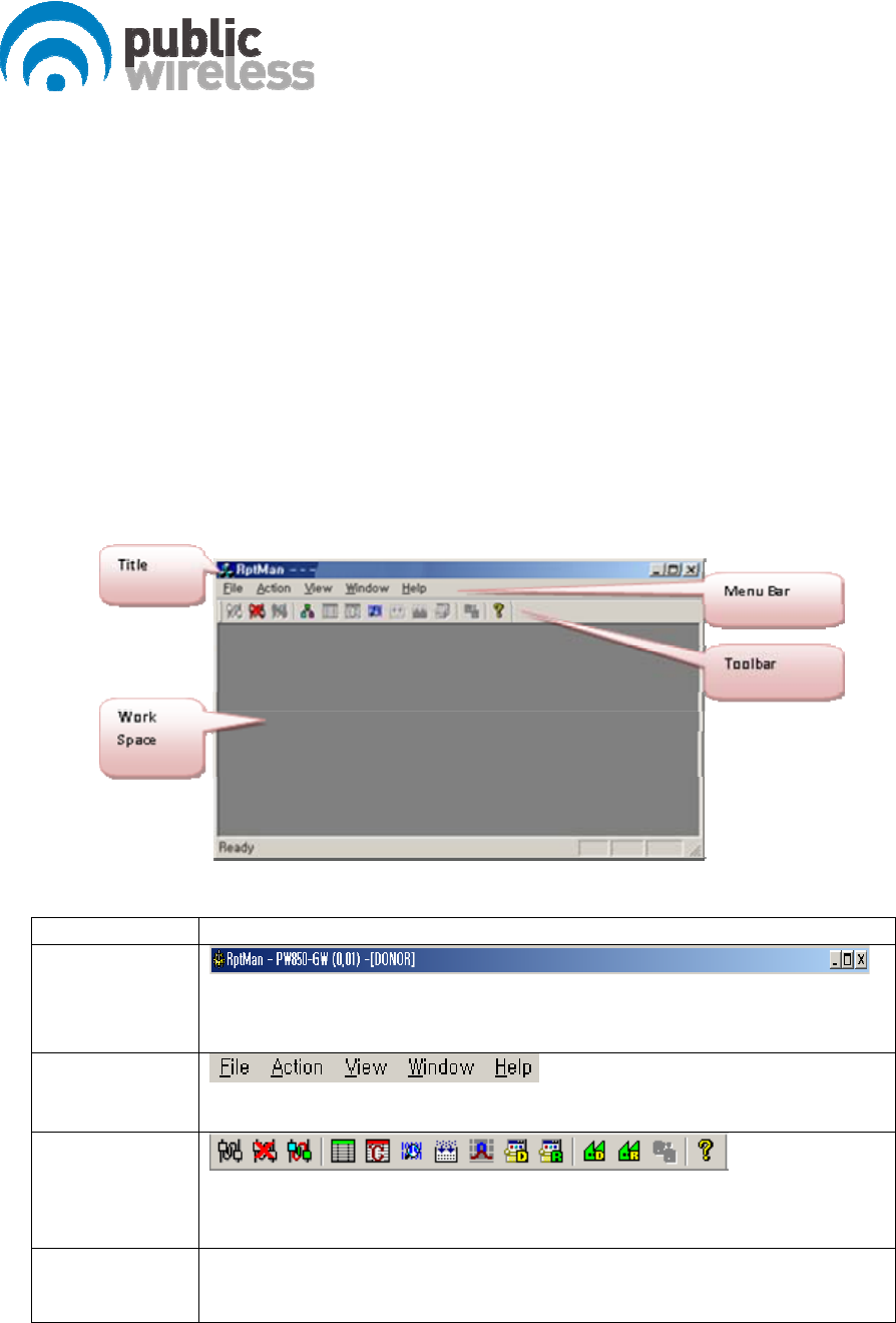
5.2. Screen
Section Description
Window Title
Displays the name of management program (GUI), i.e. RptMan.
Displays the type of equipment which is currently connected to program
(DU or RU).
Menu Bar
Presents working menu for operators.
It is associated with tool icons, which can activate the tool bar menus.
Toolbar
Presents icons (button type) for frequently used command.
User friendly icons are used.
Icons are activated or disabled as to the status of repeater.
Work Space Status information and control function are provided with a block diagram view of
DU and RU.
Provides the working space of windows or dialogs.
5.3. Status Display
Status of repeater is displayed by LED and values. The meanings are as follows.
13 / 17
z LED
Alarm: / blinking means ALARM, means NORMAL
On/Off: ON, OFF
Exception) for HPA, is ON, is OFF
z Value
Units are not displayed (omitted).
Value displayed in box ( )
z Control
The shape of mouse cursor is changed to on controllable item.
The texts of controllable LED or values are displayed in BOLD font.
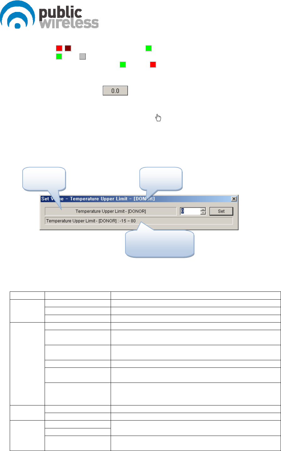
5.4. Control Policy
z System parameter is controlled one at a time.
z Click a control item (button) to popup a control popup dialog.
z Once a dialog popup window is opened, it stays there for repeated control.
5.5. Menu
Menu Sub Menu Function
Connect Connects GUI and repeater to communicate
Disconnect Disconnects GUI and repeater
File
Exit Finishes admin program.
Power Table Presents a dialog to manipulate RF power table
TC Table Presents a dialog to manipulate temperature compensation
table
Image Compression Compressed the firmware file (executable file of repeater) to
download
Image Downloader Downloads compressed firmware file to repeater
Factory Setting Sets configured values of repeater back to values of factory
settings
Action
Gain Setting Tx: set ATT to have 33dBm remote HPA output.
Rx: set ATT to have 40dB gain of Rx path including optical
loss.
Donor Window Presents DU status window in work space
View Remote Window Presents RU status window in work space
Cascade
Tile Horizon
Cascade or tile horizon arrangement of repeater status
windows in work space
Window
Packet Debug Presents debug window in work space displaying packets
between repeater and GUI program
Configurable
Item
Target
Equip. (DU
or RU)
Showing range and the
result of control
14 / 17
Help About RptMan Displays version of GUI program named RptMan (Repeater
Manager)
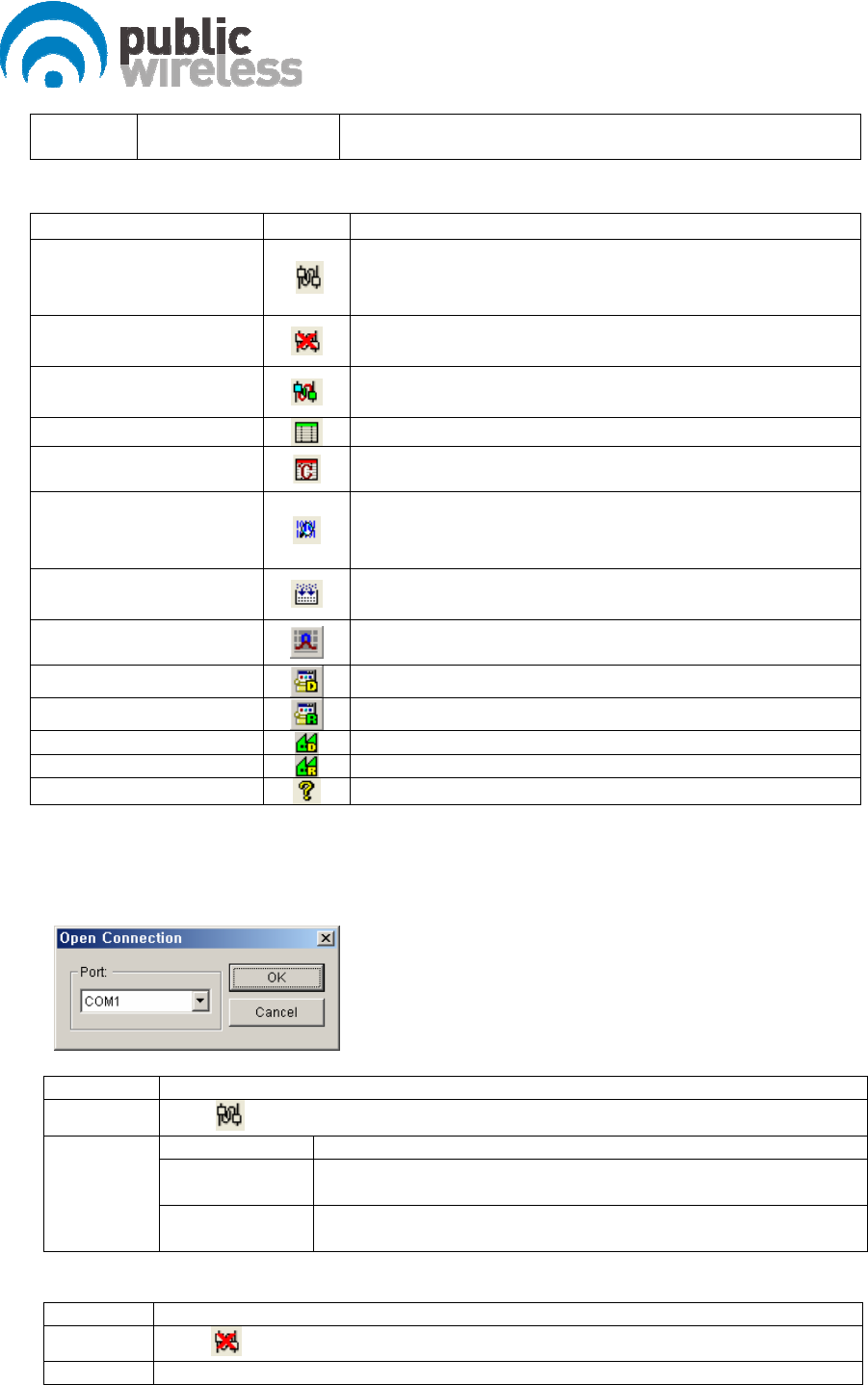
5.6. Toolbar
ITEM ICON Function
Communication
Establishment
Establishes RS-232C connection to the repeater, then
GUI starts to communicate and status of repeater are
polled and displayed.
Communication
Disconnection
Disconnects communication with connected repeater.
Status of repeater is not updated.
Polling Stop/Resume
Stops or resumes polling action of GUI program.
(activated in toggling way)
Power Table Presents a dialog to manipulate RF power table
T/C table
Presents a dialog to manipulate temperature compensation
table
Debug Packet
Displays packet data between GUI and repeater like
protocol analyzer and it may help debugging of
software
Compression of image
file
Compresses image file of repeater
Gain Setting
TX: set ATT to have 33dBm HPA
RX: set ATT to have 40dB gain of Rx path
Donor Download Download donor firmware files to a designated equipment.
Remote Download Download remote firmware files.
Donor Factory Setting Changes donor parameters to factory setting.
Remote Factory Setting Changes remote parameters to factory setting.
Help Shows version information
5.7. Program operation
5.7.1. Initiating communication
Function Establishment of communication between GUI and repeater
Method Click button in toolbar of GUI program
Port Combo box to choice com port (COM1, COM2, …)
OK Button Initiates communication between GUI and repeater, then close this
popup window(“Open Connection”)
Description
Cancel Button Cancels communication establishment and close the popup
window
5.7.2. Disconnection
Function Disconnection of GUI and repeater
Method Click button in toolbar of GUI program
Description GUI on PC and repeater disconnect communication with each other by this action.
15 / 17
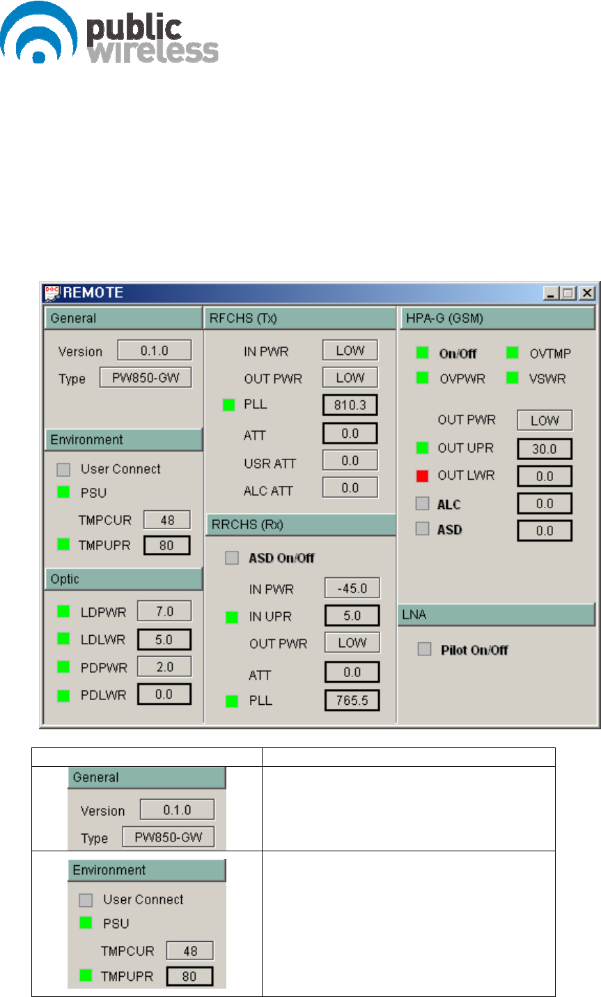
5.7.3. CM150D-01 RU Status Retrieval and Control
Group Description
z Version: Version of firmware
z Type: Type of repeater
z User Connect: Connection status of
COM port of repeater
z PSU: Status of PSU
z TMPCUR: Current temperature of
repeater
z TMPUPR: Value/control of upper
threshold of temperature (button) and
alarm status (LED)
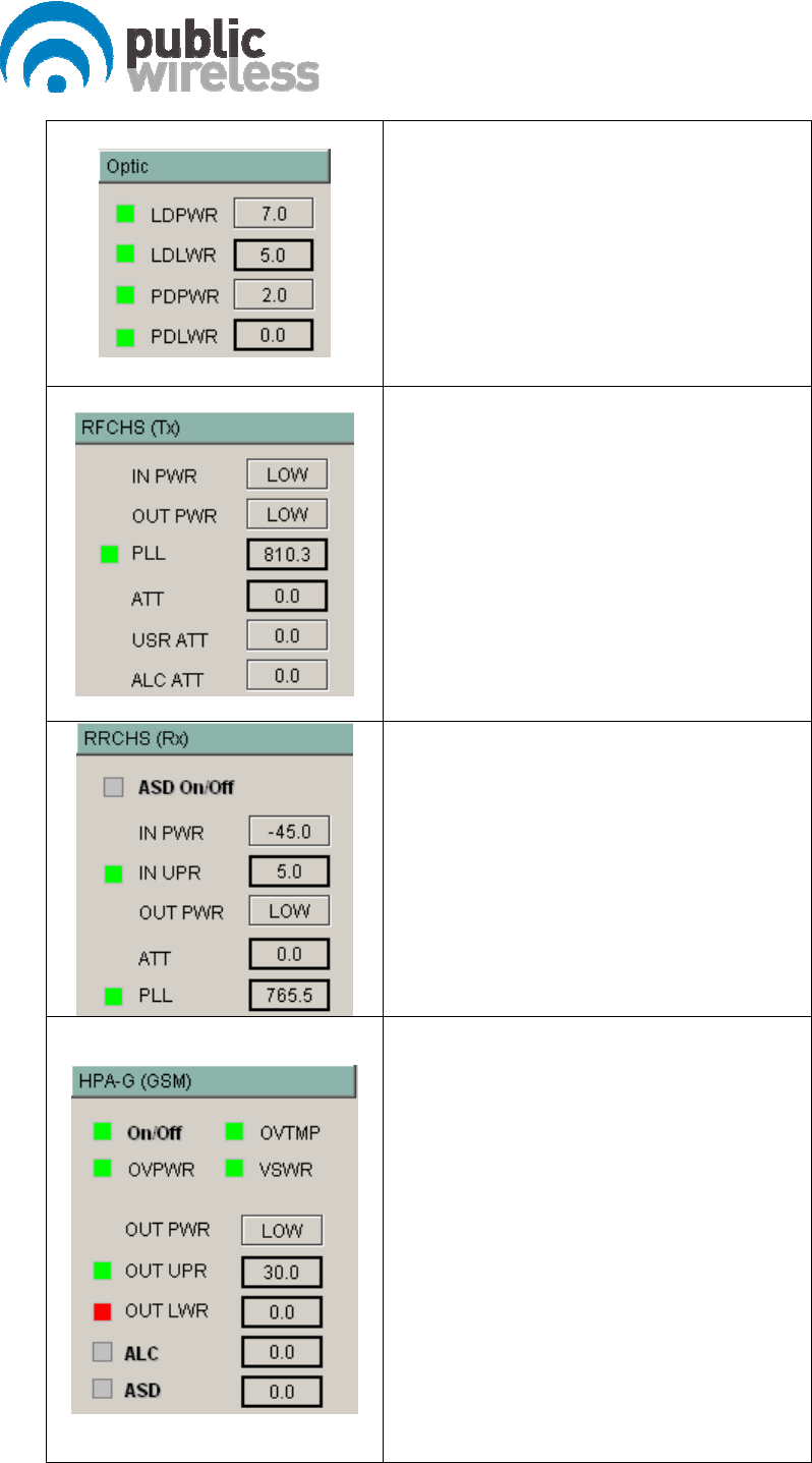
16 / 17
z LDPWR: Value of LD power (box) and
status of LD (LED)
z LDLWR: Value/control of lower threshold
of LD power (button) and lower alarm
status of LD power (LED)
z PDPWR: Value of PD power (box) and
status of PD (LED)
z PDLWR: Value/control of lower threshold
of PD power (button) and lower alarm
status (LED)
z INPWR: FWD RF input power display
z OUTPWR: FWD RF output power display
z PLL: Set PLL value, and shows PLL alarm
status
z ATT: Set ATT to control FWD level, and
shows it s value. When ATT is set manually,
ALC ATT is set to zero, and USR ATT is set
to ALC ATT + (ATT change).
Displayed ATT value = USR ATT + ALC ATT
z USR ATT: When ATT is set, USR ATT is set to
ALC ATT + (ATT change).
z ALC ATT: It is automatically adjusted by HPA
ALC to control FWD gain, and it is set to “0”
when ATT is controlled.
z ASD: When input upper threshold alarm
occurs, set ASD activation, and shows its
status.
z IN PWR: RVS input power value
z IN UPR: Set RVS input upper threshold, and
shows the alarm status of input upper
threshold RVS.
z OUTPWR: RVS RF output power
z ATT: Set ATT to control RVS level, and shows
it s value.
z PLL: Set PLL value, and shows PLL alarm
status
z On/Off: Status/control the operation
state of HPA
z OVTMP: Alarm status of HPA Over-
temperature
z OVPWR: Alarm status of HPA Over-
Power (LED)
z VSWR: Alarm status of HPA VSWR (LED)
z OUT PWR: Output power level of HPA
(box)
z OUT UPR: Value/control of upper
threshold of HPA output power (button),
alarm status (LED)
z OUT LWR: Value/control of lower
threshold of HPA output power (button),
alarm status (LED)
z ALC: Set ALC level for HPA output, and
shows ALC status. RFCHS ALC ATT is used

17 / 17
to control HPA level.
z ASD(Auto Shutdown): ASD level
(button), e running status of function
(LED)
z Pilot On/Off: Set CW signal generation, and
shows its status. It is used for RVS gain
setting.