Public Wireless CM200D01 DUAL OPTICAL DAS REPEATER User Manual CM200D01 Manual v01x
Public Wireless, Inc DUAL OPTICAL DAS REPEATER CM200D01 Manual v01x
UserManual.wiki
>
Public Wireless
>
CM200D01 User Manual
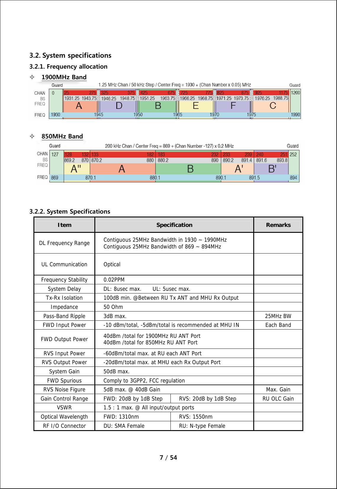
Users Manual
Navigation menu
Upload a User Manual
Namespaces
Wiki Guide
HTML
PDF
Info
Views
User Manual
Discussion / Help
Navigation

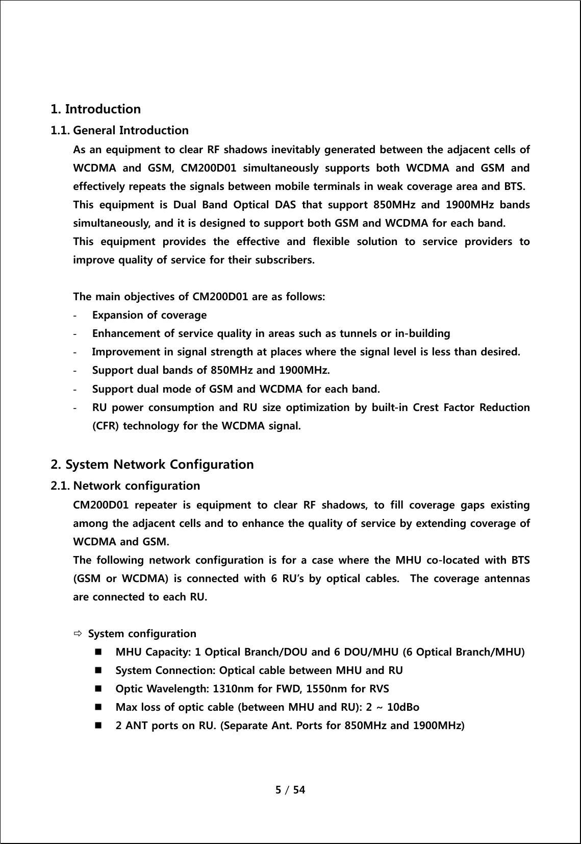
![6 / 54 [Network Configuration of Dual Band Optical DAS] 3. System Specifications 3.1. General Specifications Item CM200D01 MHU CM200D01 RU Enclosure Type 7U-Shelf type 19” standard rack mountable In-door use Cabinet Dimension (mm) W H D 19"(482.4) X 310(7U) X 450mm 127(H) X 559(W) X 211(D)mm Power Supply 120Vac (Tolerance ±10%), 60Hz TBD Power Connector ID-NO3BEH TBD RF In/Out Port SMA Female, rear side N Type Female, bottom side Optic Connector Type FC/APC, front side FC/APC, bottom side Optic Wavelength FWD: 1310nm / RVS: 1550nm Operating Temperature -5℃ ~ 40℃ -5℃ ~ 50℃ Environmental requirement The repeater RU shall be operated in the temperature range of -5℃ ~ 50℃](https://usermanual.wiki/Public-Wireless/CM200D01/User-Guide-1339879-Page-6.png)
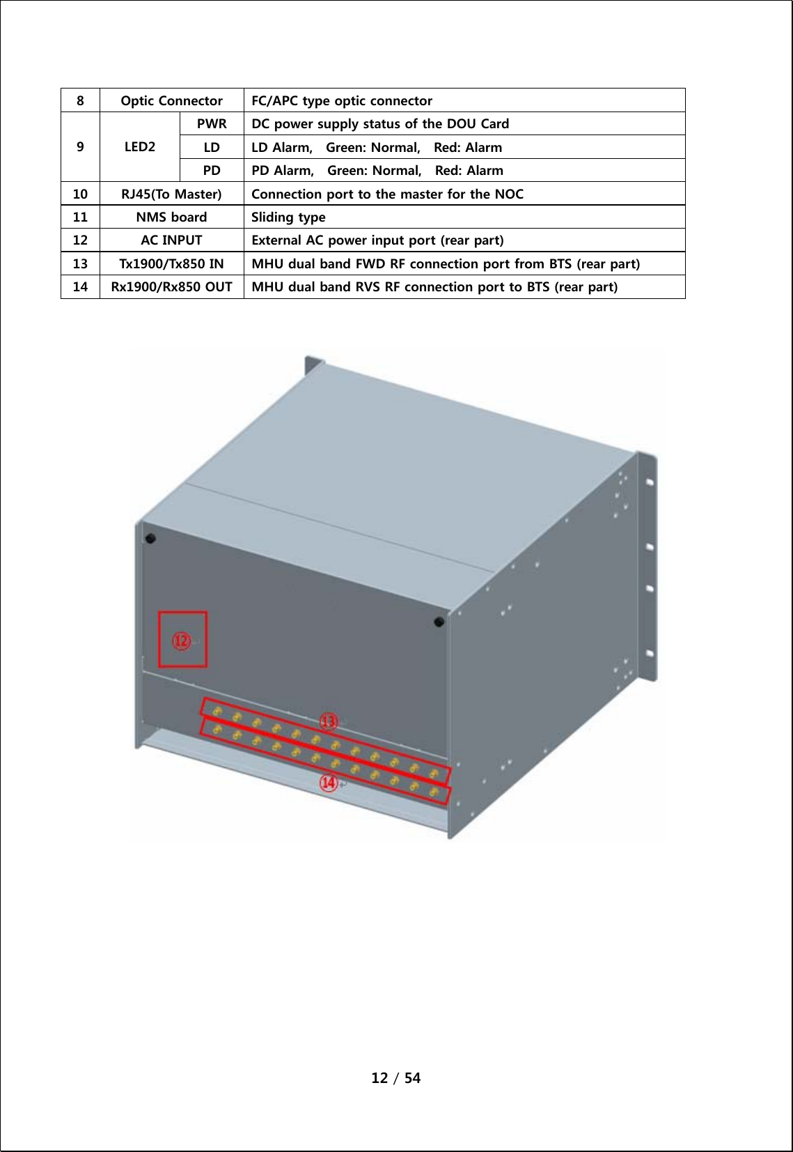
![8 / 54 4. Mechanical Specifications 4.1. CM200D01 MHU 4.1.1. Mechanical Design [FRONT] [REAR]](https://usermanual.wiki/Public-Wireless/CM200D01/User-Guide-1339879-Page-8.png)
![9 / 54 [MHU Figure] 4.1.2. Dimension](https://usermanual.wiki/Public-Wireless/CM200D01/User-Guide-1339879-Page-9.png)
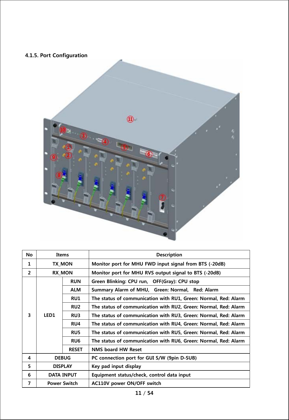
![10 / 54 4.1.3. Mechanical specification No Items Specifications 1 Exterior view 1. Shelf attachable type to both INDOOR and OPEN RACK 2. W 19"(482.4) X H 310(7U) X D 450mm 3. Weight: 15.5 Kg (1DOU included) 2 Material Aluminum (AL5052, AL6063) is mainly used for protection from corrosion by outdoor conditions. 3 Connector Type 1. Optic I/O: FC/APC at front side 2. RF I/O: SMA Female at rear side 3. Monitor port: SMA Female at front side 4 Power Input 1.Power: 110-120Vac, 60Hz 2.Connector: IN-NO3BEH 5 Ground 14SQ 2Hole ground pipe (right side of shelf) and M4 “O” rug ground (rear side of shelf) 6 Communication Port 9P D-SUB (GUI) and RJ-45 at front side 4.1.4. Descriptions of CM200D01 MHU [Forward Path] The signal from GSM or WCDMA BTS is fed to the RF input port of MHU. First, MHU RVS/FWD COMbiner(MRFCOM) module measures the input signal power level and combines the signal with te modem signal (360MHz). The combined signal then gets transmitted to RU via optical cable. [Reverse Path] The WCDMA or GSM RVS signal input from RU through the optic module is separated into RF and modem signal, and then RF RVS signal level is measured by the MRFCOM module. The RF signal then is fed to the BTS.](https://usermanual.wiki/Public-Wireless/CM200D01/User-Guide-1339879-Page-10.png)
![13 / 54 4.1.6. Module Composition No Module Voltage Used Remarks ① MHU NMS Controller 9Vdc ② MHU PSU(Power Supply Unit) 9Vdc/6.5Vdc ③ MRFCOM(MHU RVS FWD Combiner) 6.5Vdc ④ MHU FSK Modem 9Vdc ⑤ MHU Optical Transceiver Unit (DOU) 6.5Vdc [NMS UNIT] [PSU] [DOU] ⑤ ① ② ③ ④](https://usermanual.wiki/Public-Wireless/CM200D01/User-Guide-1339879-Page-13.png)
![14 / 54 4.1.7. Function of modules No Module Functions 1 [MHU NMS Controller] Monitors/controls the status and configurable items of each module in MHU 2 [PSU] Converts AC110V into DC9V and DC6.5V, and provide supply voltage to each module in MHU 3 [MRFCOM] Detects the FWD/RVS RF signal power level of input/output ports of the MHU. Also provides the connection pin to NMS controller and FSK modem. This module combines/divides the RF signal and FSK modem signal. Provides -20dB monitor port for Tx input/Rx output. 4 [FSK Modem] Data modem for MHU and RU communication MHU → RU frequency: 360MHz RU → MHU frequency: 340MHz 5 [DOM] Converts E/O(or O/E) the FWD and RVS signals. Wavelength: Tx 1310[nm], Rx 1550[nm]](https://usermanual.wiki/Public-Wireless/CM200D01/User-Guide-1339879-Page-14.png)
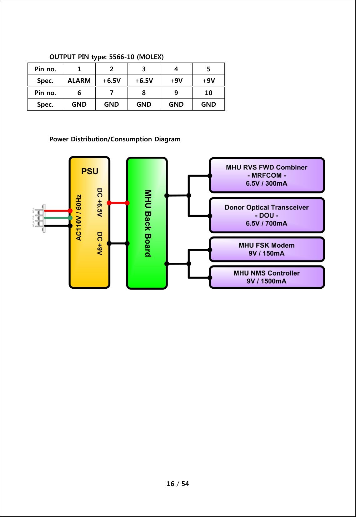
![15 / 54 4.1.8. PSU PSU converts external AC110V into DC and supplies +9V, +6.5V to each module in MHU. The drawing of PSU is as follows. SWITCHF.GAC_NAC_LINPUT+9V+6.5VALM+6.5V+9VOUTPUTPWR ONGNDGNDGNDGNDGNDYW396-05V(연호전자) [PSU Capacity] Output Voltage Maximum current Watt +9V 3 A +6.5V 5 A 59.5 W [PSU Pin Map] SWITCH PIN Type: YW396-02V Pin no. 1 2 Spec. Switch_IN Switch_Out INPUT PIN Type: YW396-05V Pin no. 1 2 3 4 5 Spec. AC_L N.C AC_N N.C F.G](https://usermanual.wiki/Public-Wireless/CM200D01/User-Guide-1339879-Page-15.png)
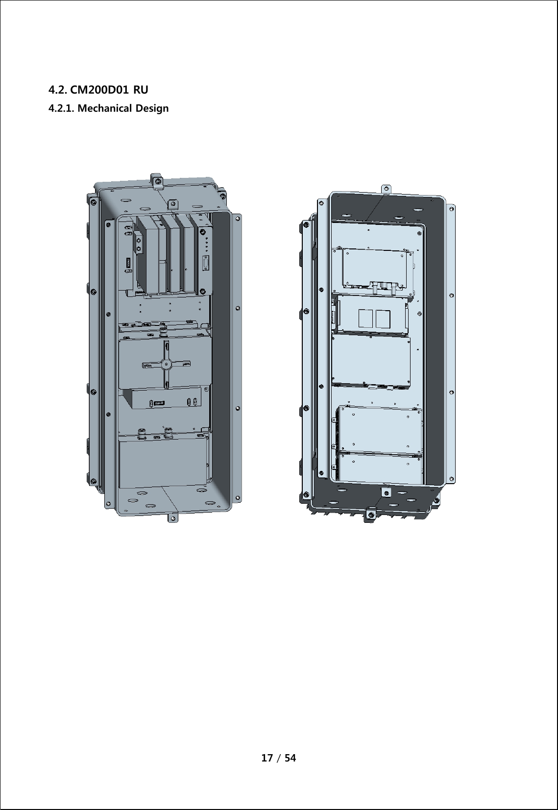
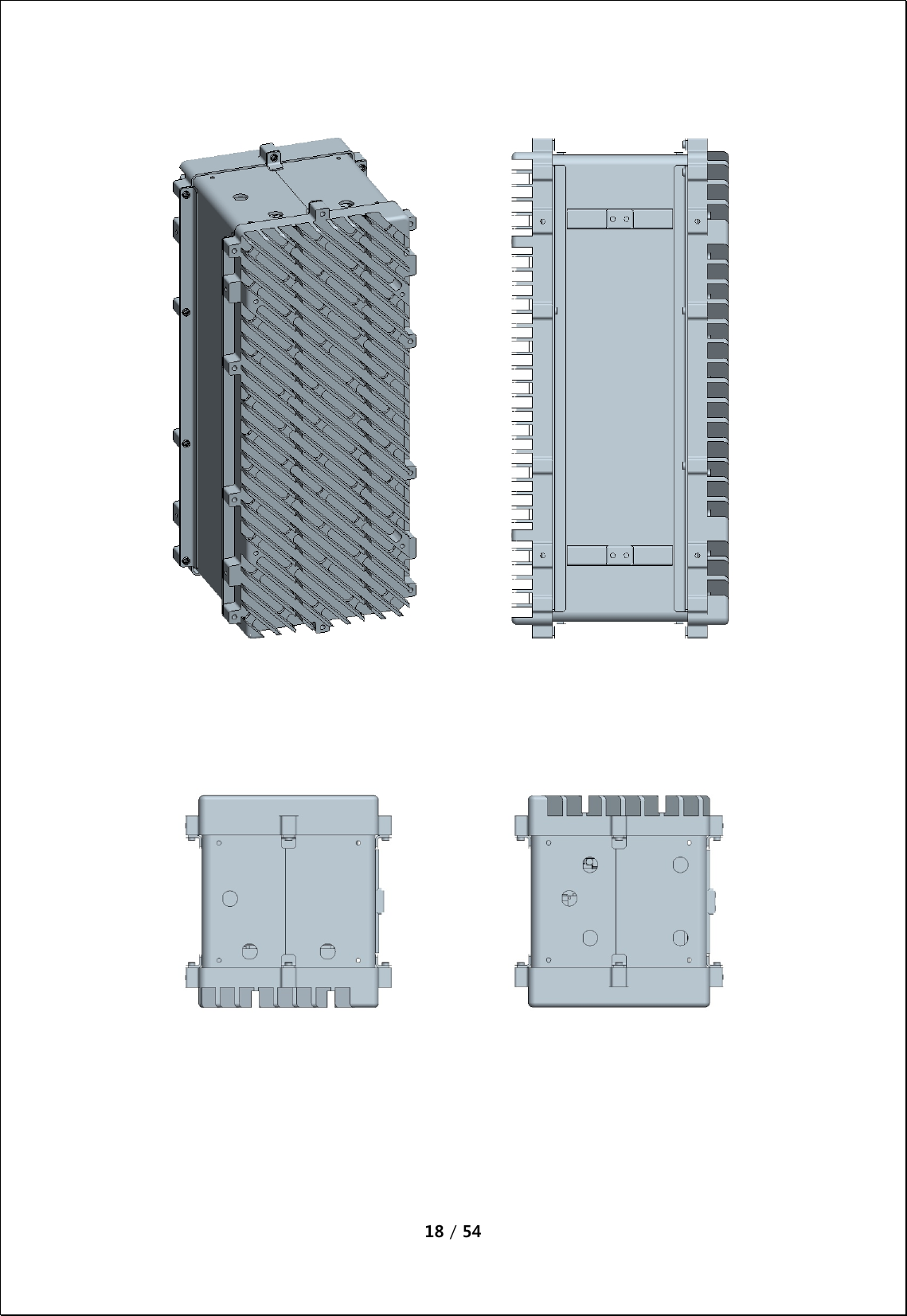
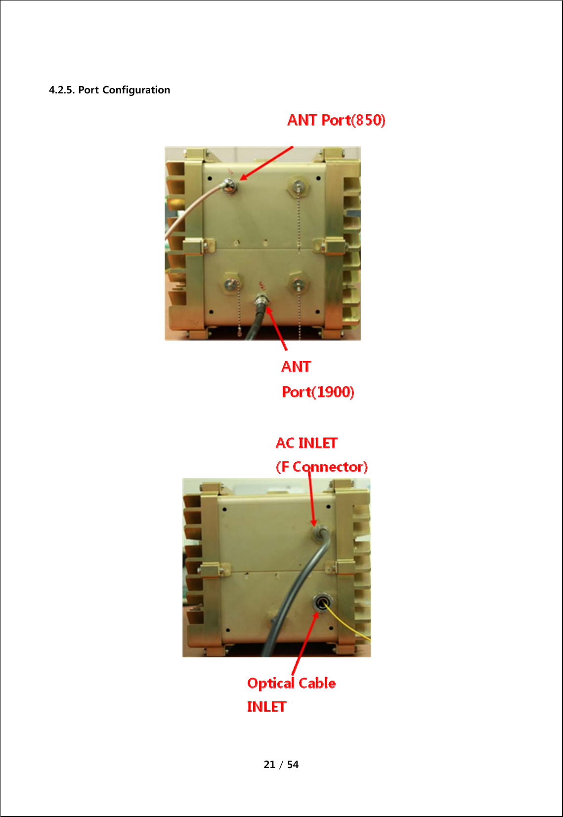
![19 / 54 4.2.2. Dimension RU System picture and Size 127(H) X 559(W) X 211(D) mm [Side] [Inner Side] [Front/Rear Side] 4.2.3. Mechanical Specification No Item Description 1 Dimension & Weight 1. Dimension: 127(H) X 559(W) X 211(D) mm (plinth included) 2. Weight: TBD Kg 2 Method of Cooling Natural convection (Heat-sink) 3 Door Locking Type 10 on each side using bolt lock 4 Optic Connector 1. Position: Cabinet inside 2. Connector type: FC/APC * Optic cable tray is provided inside of cabinet. 5 ANT PORT 1. located at the bottom side of cabinet 2. Connector Type: N Type Female 6 Power Input 1. Power: TBD 2. Position: bottom side of cabinet 3. Connector: TBD 7 Ground TBD 8 Waterproof condition IP65 compliant 9 Misc. Features 1. Easy to maintain 2. Pole mountable (i.e., telegraph pole) 3. Torque hinge used](https://usermanual.wiki/Public-Wireless/CM200D01/User-Guide-1339879-Page-19.png)
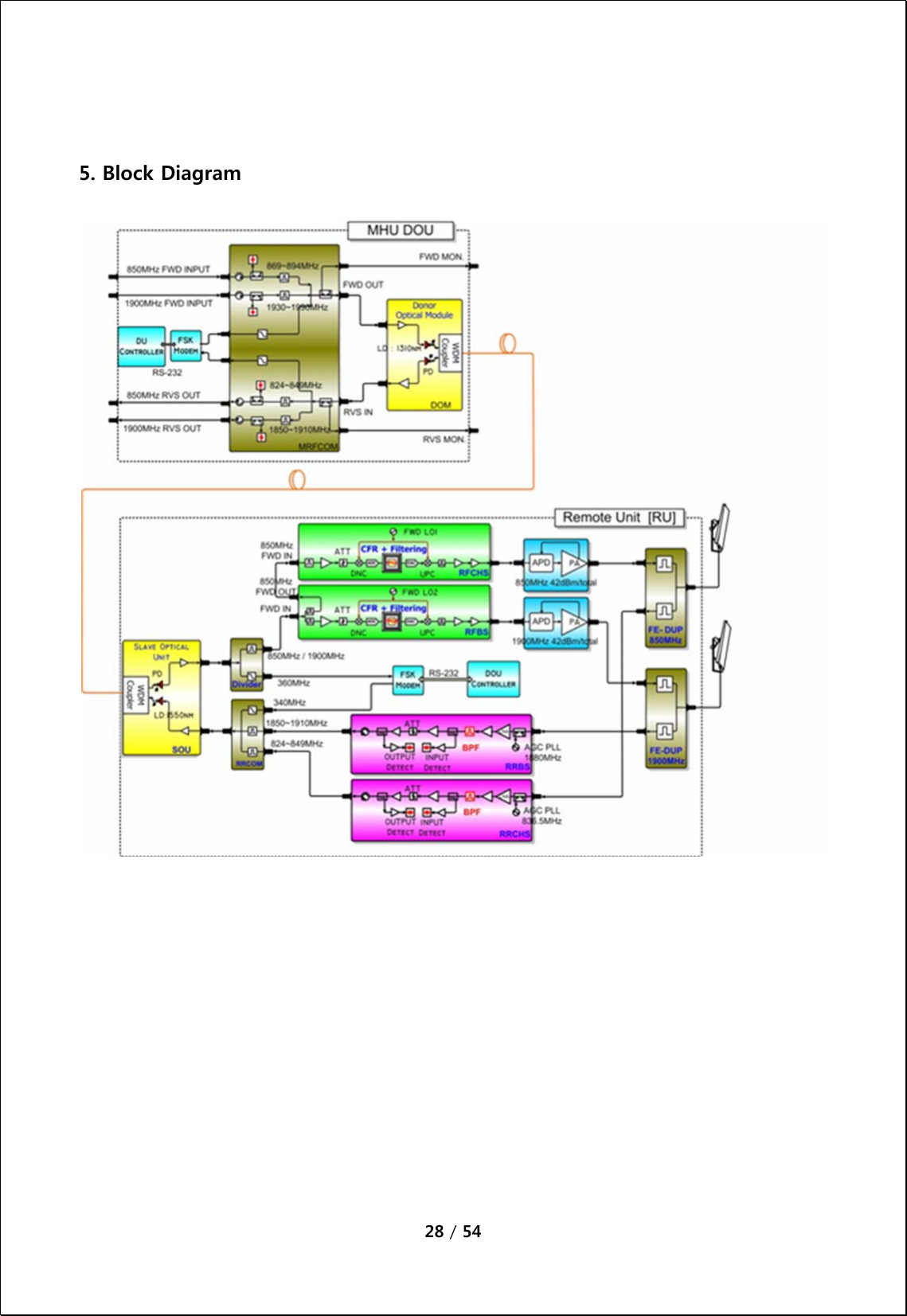
![20 / 54 4.2.4. Description of CM200D01 RU [Forward path] The RF and modem combined signals sent from the optic module of MHU is first divided into RF and modem signals at Divider in RU, then the 1900MHz Tx RF signal is amplified and filtered at the RFBS module, 850MHz Tx RF signal is amplified and filtered at the RFCHS module. The modem signal is conveyed to CPU of NMS controller through FSK modem. WCDMA signal is reduced by the Crest Factor passing through the CFR FPGA digital board inside RFBS and RFCHS. This technology enables reduction of PAPR for WCDMA signal increasing HPA efficiency. A higher efficiency HPA allows using a smaller enclosure with lower power consumption while decreasing OPEX for the service provider. The GSM and WCDMA RF signals from the RFBS module is linearly amplified up to high power level on HPA, passed through the Front-End Filter Unit, and finally transmitted through an antenna. [Reverse Path] GSM and WCDMA Rx signals incoming from 1900MHz or 850MHz antenna are first passed by the Front-End Filter Unit, amplified by a low noise and high gain amplifier, filtered in RRBS(for 1900MHz band) or RRCHS(for 850MHz band), and combined with modem signal at combiner(RRCOM). The combined signal is then transmitted to MHU through the optic module.](https://usermanual.wiki/Public-Wireless/CM200D01/User-Guide-1339879-Page-20.png)
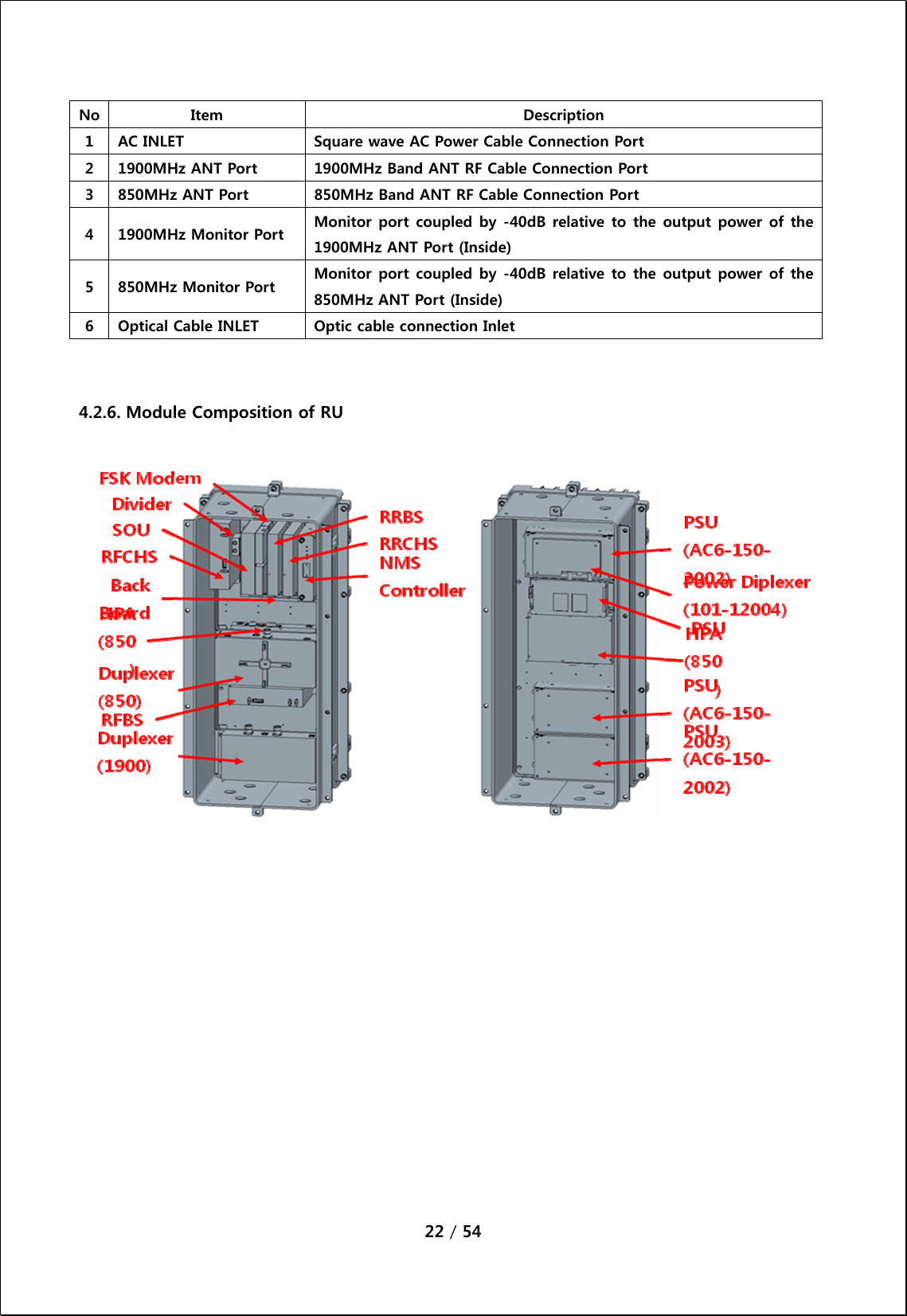
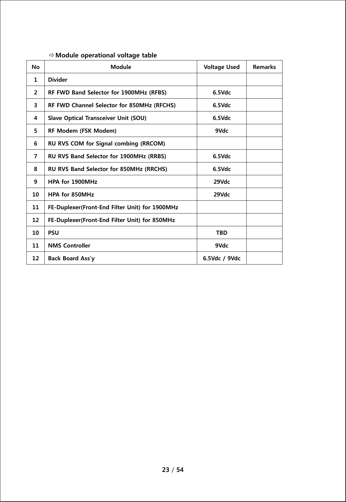
![24 / 54 4.2.7. Function of Modules No Module Description 1 [Divider] Divides signals into RF and modem signals and sends to RFBS/RFCHS and FSK modem. 2 [RFBS] Controls the gain of 1900MHz FWD path, filters FWD band, controls the crest factor of 1900MHz FWD signal, and performs the ALC function. Output of the module is sent to 1900MHz HPA. 3 [RFCHS] Controls the gain of 850MHz FWD path, filters FWD band, controls the crest factor of 850MHz FWD signal, and performs the ALC function. Output of the module is sent to 850MHz HPA. 3 [SOU] Performs E/O (or O/E) conversion for FWD and RVS signals. Wavelength: TX 1550[nm], RX 1310[nm] 4 [FSK Modem] Data modem for RU and MHU communication RU → MHU frequency: 340MHz MHU → RU frequency: 360MHz 5 [RRCOM] Combines RVS 850MHz, 1900MHz and Modem signals, and provides the combined signal to optical module in order to perform E/O conversion. 6 [RRBS] Amplifies RVS 1900MHz signal by low noise high gain, filters for the desirable band and controls the RVS path gain of RU. 6 [RRCHS] Amplifies RVS 850MHz signal by low noise high gain, filters for the desirable band and controls the RVS path gain of RU.](https://usermanual.wiki/Public-Wireless/CM200D01/User-Guide-1339879-Page-24.png)
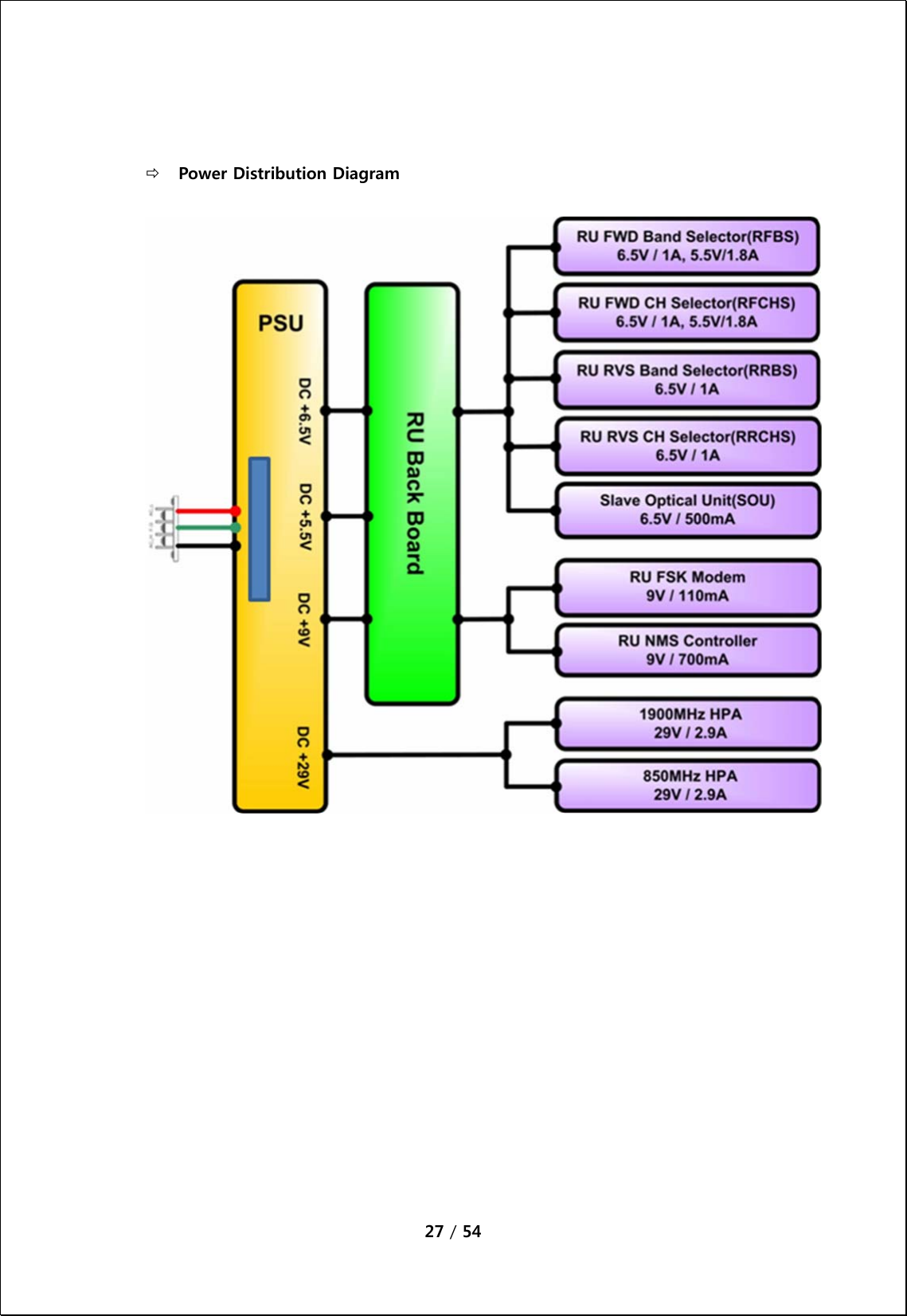
![25 / 54 8 [1900MHz HPA] 16Watt(42dBm) High power amplifier that amplifies the RU 1900MHz signal by linearizer and sends to RU ANT through the 1900MHz FE-Duplexer. 8 [850MHz HPA] 16Watt(42dBm) High power amplifier that amplifies the RU 850MHz signal by linearizer and sends to RU ANT through the 850MHz FE-Duplexer. [1900MHz FE-Duplexer] Front end duplexer that passes through 1900MHz desired FWD and RVS frequency bands. 9 [850MHz FE-Duplexer] Front end duplexer that passes through 850MHz desired FWD and RVS frequency bands. 10 [PSU] Converts DC TBD V to DC 29V/9V/6.5V/5.5V, and distributes the necessary power to each modules. 11 [NMS Controller] Monitors the status of modules in RU and controls the configurable parameters of the RU modules. 12 [Interface BD] Provides operating voltage and monitors/controls signal to modules connected to interface B’D. Also provides a connection port to communicate with NMS B’D.](https://usermanual.wiki/Public-Wireless/CM200D01/User-Guide-1339879-Page-25.png)
![26 / 54 [PSU] Converts SQAC to DC 29V [PSU] Converts SQAC to DC 12V [Power Diplexer] Divide SQAC input](https://usermanual.wiki/Public-Wireless/CM200D01/User-Guide-1339879-Page-26.png)