Public Wireless CM200D01 DUAL OPTICAL DAS REPEATER User Manual CM200D01 Manual v01x
Public Wireless, Inc DUAL OPTICAL DAS REPEATER CM200D01 Manual v01x
Users Manual

CM200D01
User Manual
2010

2 / 54
Content
1. Introduction....................................................................................................................................................................5
1.1. General Introduction.....................................................................................................................................5
2. Network configuration of system.........................................................................................................................
2.1. Network configuration.................................................................................................................................5
3. System Specifications ................................................................................................................................................6
3.1. General Specifications..................................................................................................................................6
3.2. System specifications....................................................................................................................................7
3.2.1. Frequency allocation........................................................................................................................7
3.2.2. System Specifications......................................................................................................................7
4. Mechanical Specifications .......................................................................................................................................8
4.1. CM200D01 MHU .............................................................................................................................................8
4.1.1. Mechanical Design............................................................................................................................8
4.1.2. Dimension .............................................................................................................................................9
4.1.3. Mechanical specification ............................................................................................................10
4.1.4. Descriptions of CM200D01 MHU...........................................................................................10
4.1.5. Port Configuration.........................................................................................................................11
4.1.6. Module Composition....................................................................................................................13
4.1.7. Function of modules.....................................................................................................................14
4.1.8. PSU ........................................................................................................................................................15
4.2. CM200D01 RU ...............................................................................................................................................17
4.2.1. Mechanical Design.........................................................................................................................17
4.2.2. Dimension ..........................................................................................................................................19
4.2.3. Mechanical Specification ............................................................................................................19
4.2.4. Description of CM200D01 RU..................................................................................................20
4.2.5. Port Configuration.........................................................................................................................21
4.2.6. Module Composition of RU......................................................................................................22
4.2.7. Function of Modules ....................................................................................................................24
5. Block Diagram ............................................................................................................................................................28
6. Administration Program (RptMan-PWDUAL) ............................................................................................29
6.1. System Requirement ..................................................................................................................................29
6.2. Cable connection .........................................................................................................................................29
6.3. Screen ................................................................................................................................................................30
6.4. Status Display ................................................................................................................................................30

3 / 54
6.5. Control Policy.................................................................................................................................................31
6.6. Menu ..................................................................................................................................................................31
6.7. Toolbar...............................................................................................................................................................32
6.8. Program operation......................................................................................................................................33
6.8.1. Initiating communication...........................................................................................................33
6.8.2. Disconnection...................................................................................................................................33
6.8.3. CM200D01 MHU Status Retrieval and Control...............................................................34
6.8.4. CM200D01 RU Status Retrieval and Control....................................................................36
6.8.5. Firmware download ......................................................................................................................39
6.9. Additional features .....................................................................................................................................40
6.9.1. ASD (Auto Shutdown) Function .............................................................................................40
6.9.2. ALC (Auto Level Control) Function........................................................................................40
Appendix A Factory setting value for each equipment .................................................................................42
Appendix B 1900MHz GSM & WCDMA Frequency Map ..............................................................................43
Appendix C 850MHz GSM & WCDMA Frequency Map.................................................................................51

4 / 54
IMPORTANT NOTE:
FCC RF Radiation Exposure Statement:
This equipment complies with FCC RF radiation exposure limits set forth for an
uncontrolled environment. This equipment should be installed and operated with a
minimum distance of 20 centimeters between the radiator and your body.This
transmitter must not be co-located or operating in conjunction with any other antenna
or transmitter.

5 / 54
1. Introduction
1.1. General Introduction
As an equipment to clear RF shadows inevitably generated between the adjacent cells of
WCDMA and GSM, CM200D01 simultaneously supports both WCDMA and GSM and
effectively repeats the signals between mobile terminals in weak coverage area and BTS.
This equipment is Dual Band Optical DAS that support 850MHz and 1900MHz bands
simultaneously, and it is designed to support both GSM and WCDMA for each band.
This equipment provides the effective and flexible solution to service providers to
improve quality of service for their subscribers.
The main objectives of CM200D01 are as follows:
- Expansion of coverage
- Enhancement of service quality in areas such as tunnels or in-building
- Improvement in signal strength at places where the signal level is less than desired.
- Support dual bands of 850MHz and 1900MHz.
- Support dual mode of GSM and WCDMA for each band.
- RU power consumption and RU size optimization by built-in Crest Factor Reduction
(CFR) technology for the WCDMA signal.
2. System Network Configuration
2.1. Network configuration
CM200D01 repeater is equipment to clear RF shadows, to fill coverage gaps existing
among the adjacent cells and to enhance the quality of service by extending coverage of
WCDMA and GSM.
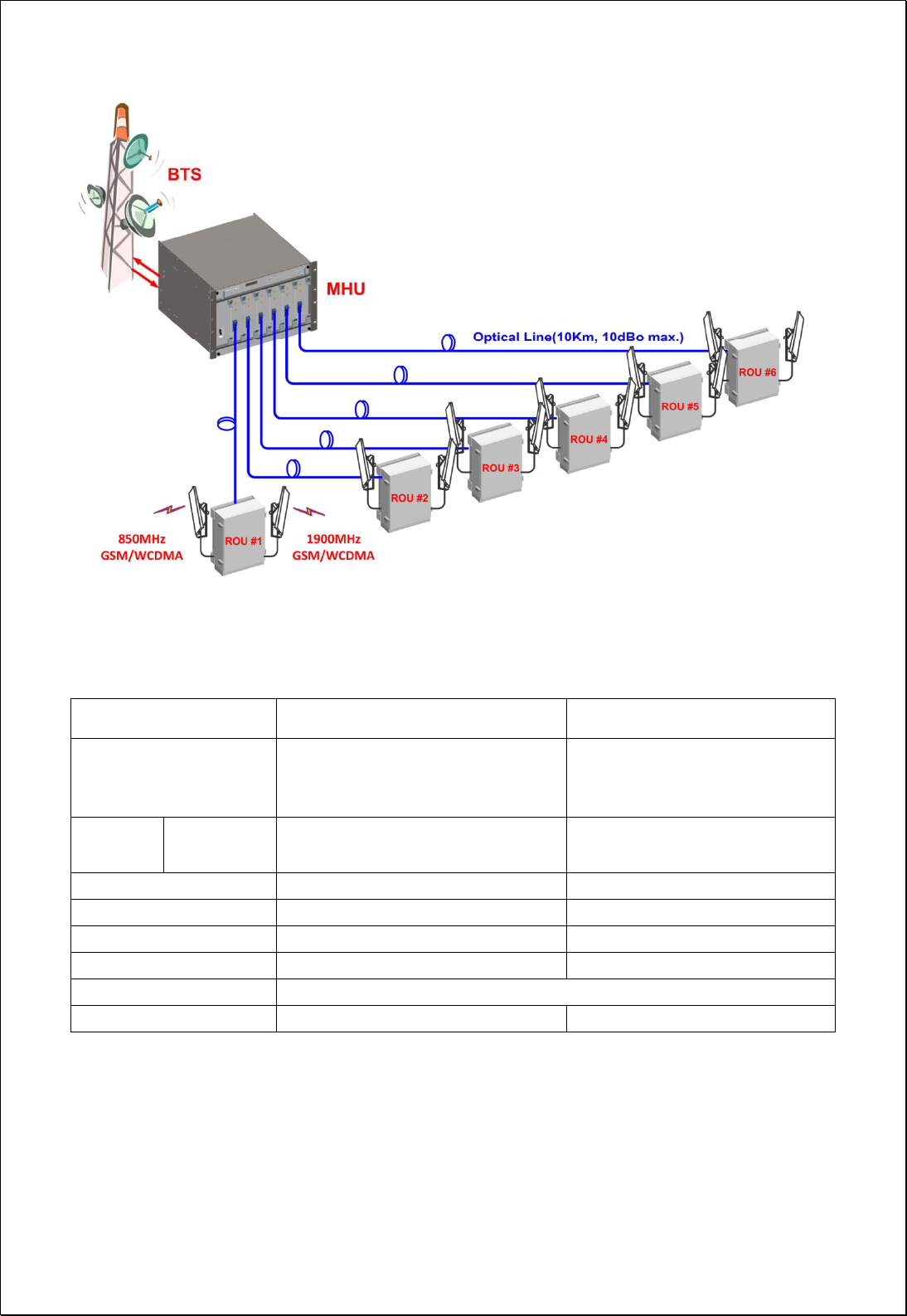
The following network configuration is for a case where the MHU co-located with BTS
(GSM or WCDMA) is connected with 6 RU’s by optical cables. The coverage antennas
are connected to each RU.
System configuration
MHU Capacity: 1 Optical Branch/DOU and 6 DOU/MHU (6 Optical Branch/MHU)
System Connection: Optical cable between MHU and RU
Optic Wavelength: 1310nm for FWD, 1550nm for RVS
Max loss of optic cable (between MHU and RU): 2 ~ 10dBo
2 ANT ports on RU. (Separate Ant. Ports for 850MHz and 1900MHz)
6 / 54
[Network Configuration of Dual Band Optical DAS]
3. System Specifications
3.1. General Specifications
Item CM200D01 MHU CM200D01 RU
Enclosure Type
7U-Shelf type
19” standard rack mountable
In-door use
Cabinet
Dimension
(mm) W H D 19"(482.4) X 310(7U) X 450mm 127(H) X 559(W) X 211(D)mm
Power Supply 120Vac (Tolerance ±10%), 60Hz TBD
Power Connector ID-NO3BEH TBD
RF In/Out Port SMA Female, rear side N Type Female, bottom side
Optic Connector Type FC/APC, front side FC/APC, bottom side
Optic Wavelength FWD: 1310nm / RVS: 1550nm
Operating Temperature -5℃ ~ 40℃ -5℃ ~ 50℃
Environmental requirement
The repeater RU shall be operated in the temperature range of -5℃ ~ 50℃
7 / 54
3.2. System specifications
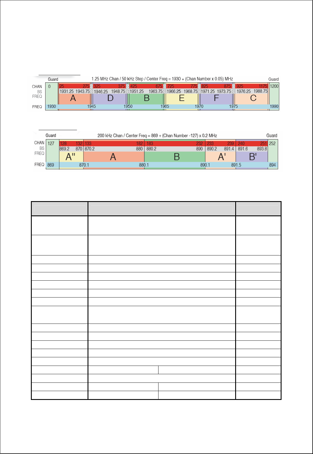
3.2.1. Frequency allocation
1900MHz Band
850MHz Band
3.2.2. System Specifications
Item Specification Remarks
DL Frequency Range Contiguous 25MHz Bandwidth in 1930 ~ 1990MHz
Contiguous 25MHz Bandwidth of 869 ~ 894MHz
UL Communication Optical
Frequency Stability 0.02PPM
System Delay DL: 8usec max. UL: 5usec max.
Tx-Rx Isolation 100dB min. @Between RU Tx ANT and MHU Rx Output
Impedance 50 Ohm
Pass-Band Ripple 3dB max. 25MHz BW
FWD Input Power -10 dBm/total, -5dBm/total is recommended at MHU IN Each Band
FWD Output Power 40dBm /total for 1900MHz RU ANT Port
40dBm /total for 850MHz RU ANT Port
RVS Input Power -60dBm/total max. at RU each ANT Port
RVS Output Power -20dBm/total max. at MHU each Rx Output Port
System Gain 50dB max.
FWD Spurious Comply to 3GPP2, FCC regulation
RVS Noise Figure 5dB max. @ 40dB Gain Max. Gain
Gain Control Range FWD: 20dB by 1dB Step RVS: 20dB by 1dB Step RU OLC Gain
VSWR 1.5 : 1 max. @ All input/output ports
Optical Wavelength FWD: 1310nm RVS: 1550nm
RF I/O Connector DU: SMA Female RU: N-type Female
8 / 54
4. Mechanical Specifications
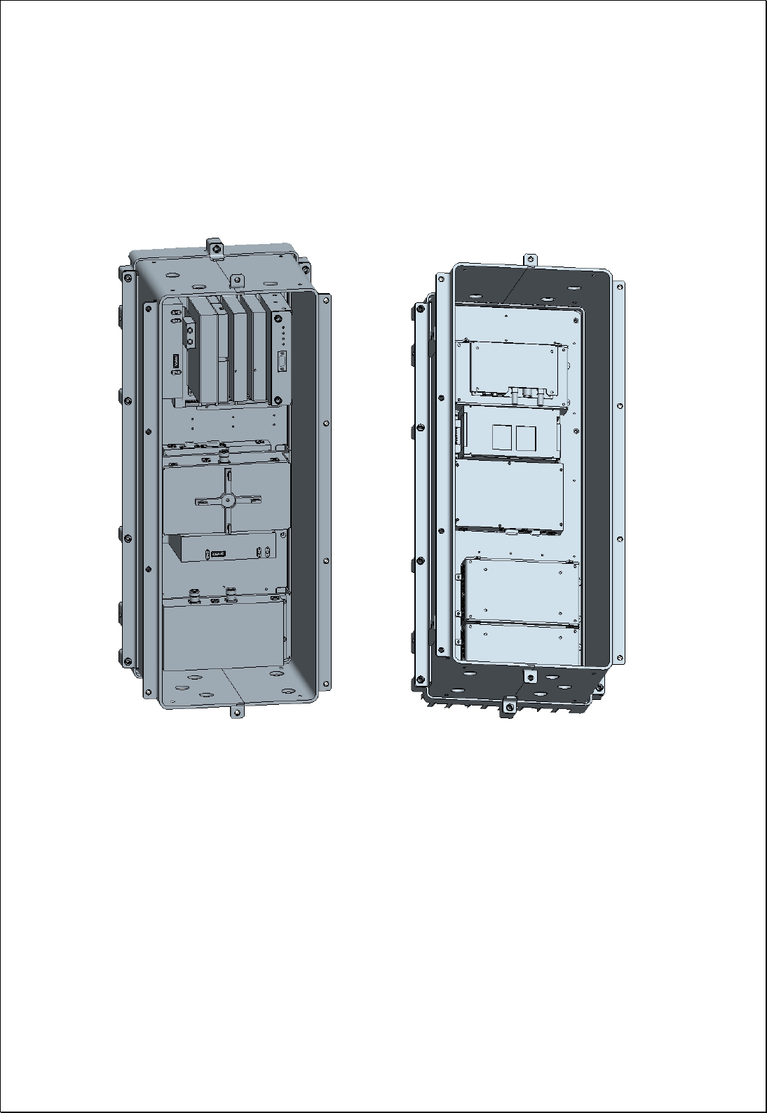
4.1. CM200D01 MHU
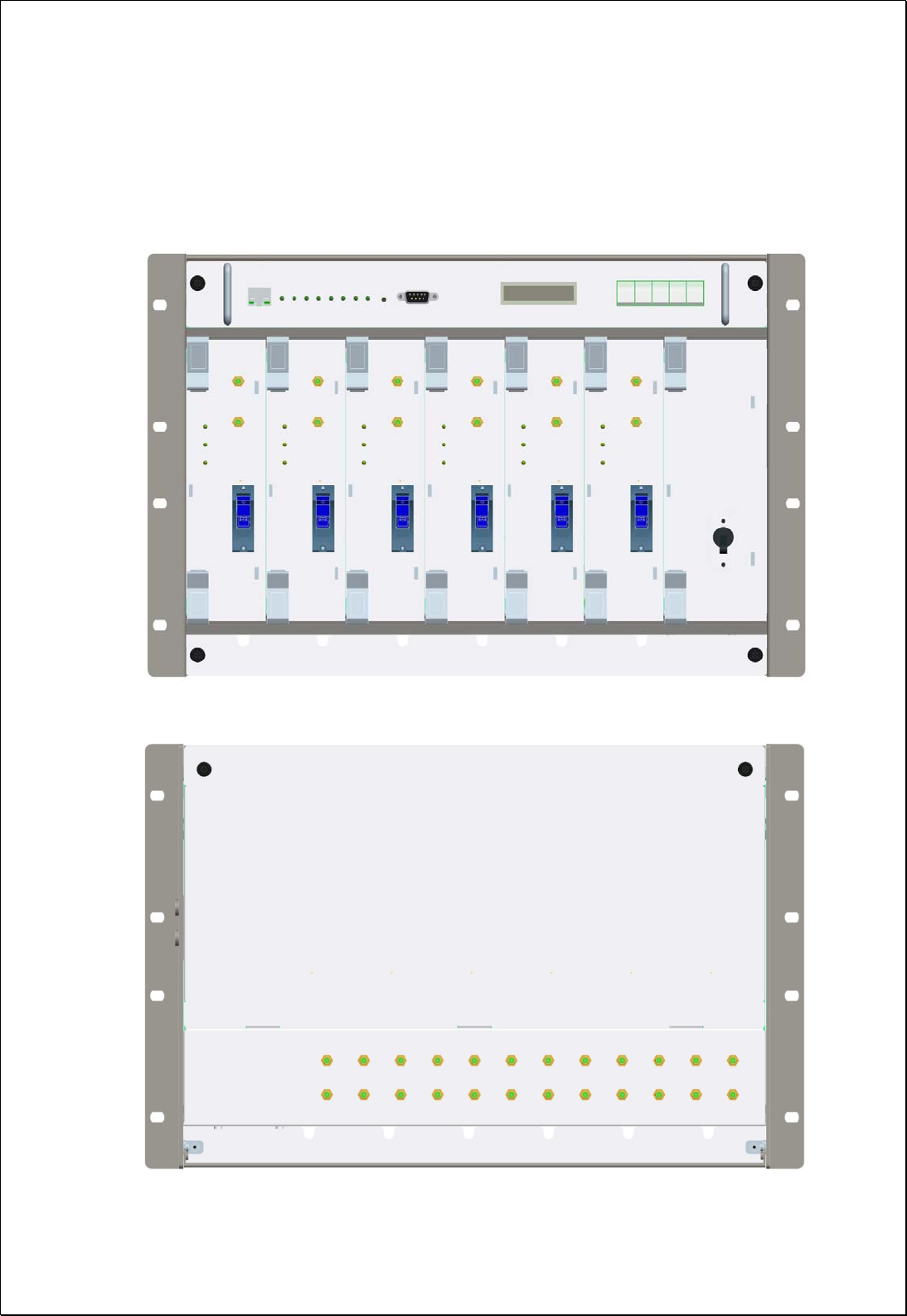
4.1.1. Mechanical Design
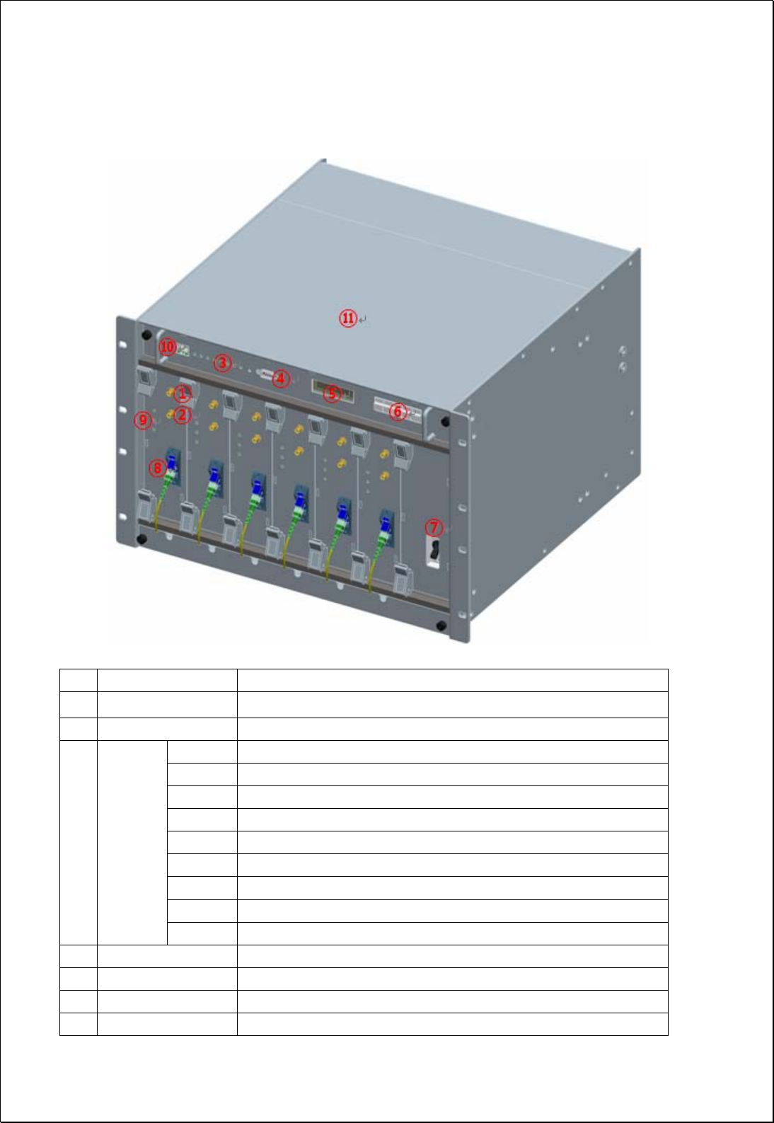
[FRONT]
[REAR]
9 / 54
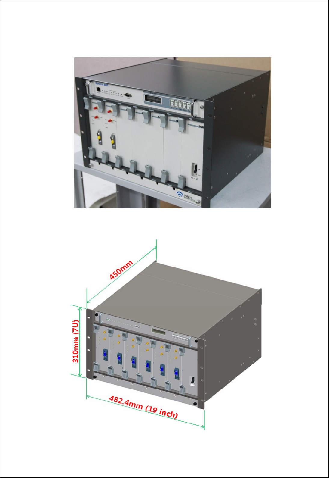
[MHU Figure]
4.1.2. Dimension

10 / 54
4.1.3. Mechanical specification
No Items Specifications
1 Exterior view
1. Shelf attachable type to both INDOOR and OPEN RACK
2. W 19"(482.4) X H 310(7U) X D 450mm
3. Weight: 15.5 Kg (1DOU included)
2 Material Aluminum (AL5052, AL6063) is mainly used for protection
from corrosion by outdoor conditions.
3 Connector Type
1. Optic I/O: FC/APC at front side
2. RF I/O: SMA Female at rear side
3. Monitor port: SMA Female at front side
4 Power Input 1.Power: 110-120Vac, 60Hz
2.Connector: IN-NO3BEH
5 Ground 14SQ 2Hole ground pipe (right side of shelf) and M4 “O” rug
ground (rear side of shelf)
6 Communication Port 9P D-SUB (GUI) and RJ-45 at front side
4.1.4. Descriptions of CM200D01 MHU
[Forward Path]
The signal from GSM or WCDMA BTS is fed to the RF input port of MHU. First, MHU
RVS/FWD COMbiner(MRFCOM) module measures the input signal power level and
combines the signal with te modem signal (360MHz). The combined signal then gets
transmitted to RU via optical cable.
[Reverse Path]
The WCDMA or GSM RVS signal input from RU through the optic module is separated
into RF and modem signal, and then RF RVS signal level is measured by the MRFCOM
module. The RF signal then is fed to the BTS.
11 / 54
4.1.5. Port Configuration
No Items Description
1 TX_MON Monitor port for MHU FWD input signal from BTS (-20dB)
2 RX_MON Monitor port for MHU RVS output signal to BTS (-20dB)
RUN Green Blinking: CPU run, OFF(Gray): CPU stop
ALM Summary Alarm of MHU, Green: Normal, Red: Alarm
RU1 The status of communication with RU1, Green: Normal, Red: Alarm
RU2 The status of communication with RU2, Green: Normal, Red: Alarm
RU3 The status of communication with RU3, Green: Normal, Red: Alarm
RU4 The status of communication with RU4, Green: Normal, Red: Alarm
RU5 The status of communication with RU5, Green: Normal, Red: Alarm
RU6 The status of communication with RU6, Green: Normal, Red: Alarm
3 LED1
RESET NMS board HW Reset
4 DEBUG PC connection port for GUI S/W (9pin D-SUB)
5 DISPLAY Key pad input display
6 DATA INPUT Equipment status/check, control data input
7 Power Switch AC110V power ON/OFF switch
12 / 54
8 Optic Connector FC/APC type optic connector
PWR DC power supply status of the DOU Card
LD LD Alarm, Green: Normal, Red: Alarm
9 LED2
PD PD Alarm, Green: Normal, Red: Alarm
10 RJ45(To Master) Connection port to the master for the NOC
11 NMS board Sliding type
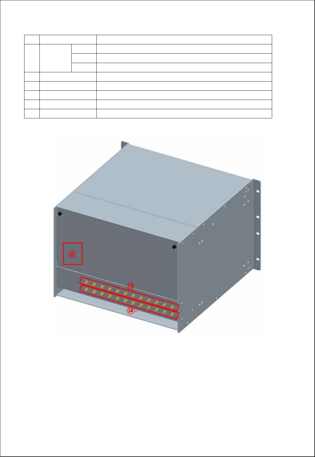
12 AC INPUT External AC power input port (rear part)
13 Tx1900/Tx850 IN MHU dual band FWD RF connection port from BTS (rear part)
14 Rx1900/Rx850 OUT MHU dual band RVS RF connection port to BTS (rear part)
13 / 54
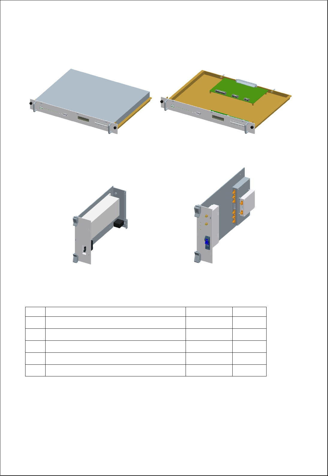
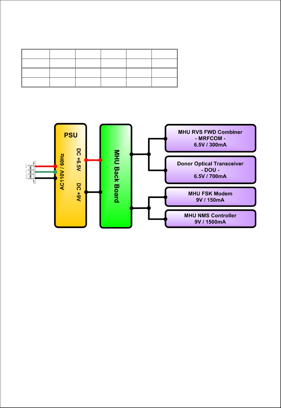
4.1.6. Module Composition
No Module Voltage Used Remarks
① MHU NMS Controller 9Vdc
② MHU PSU(Power Supply Unit) 9Vdc/6.5Vdc
③ MRFCOM(MHU RVS FWD Combiner) 6.5Vdc
④ MHU FSK Modem 9Vdc
⑤ MHU Optical Transceiver Unit (DOU) 6.5Vdc
[NMS UNIT]
[PSU] [DOU]
⑤
①
②
③
④
14 / 54
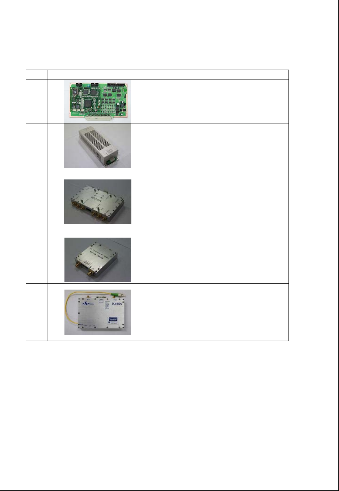
4.1.7. Function of modules
No Module Functions
1
[MHU NMS Controller]
Monitors/controls the status and configurable
items of each module in MHU
2
[PSU]
Converts AC110V into DC9V and DC6.5V, and
provide supply voltage to each module in MHU
3
[MRFCOM]
Detects the FWD/RVS RF signal power level of
input/output ports of the MHU. Also provides
the connection pin to NMS controller and FSK
modem. This module combines/divides the RF
signal and FSK modem signal. Provides -20dB
monitor port for Tx input/Rx output.
4
[FSK Modem]
Data modem for MHU and RU communication
MHU → RU frequency: 360MHz
RU → MHU frequency: 340MHz
5
[DOM]
Converts E/O(or O/E) the FWD and RVS signals.
Wavelength: Tx 1310[nm], Rx 1550[nm]
15 / 54
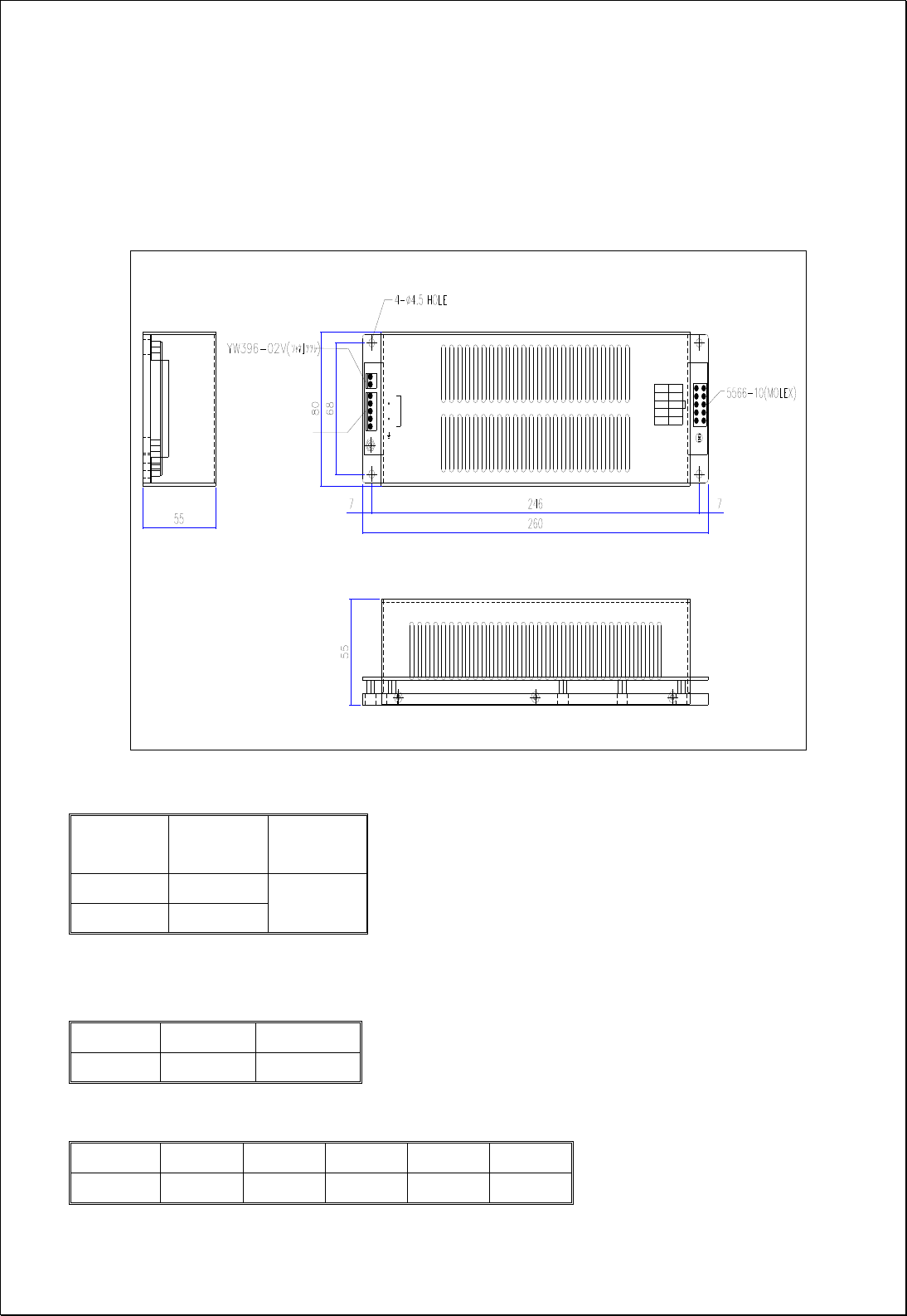
4.1.8. PSU
PSU converts external AC110V into DC and supplies +9V, +6.5V to each module in
MHU.
The drawing of PSU is as follows.
SWITCH
F.G
AC_N
AC_L
INPUT
+9V
+6.5V
ALM
+6.5V
+9V
OUTPUT
PWR ON
GND
GND
GND
GND
GND
YW396-05V(연호전자)
[PSU Capacity]
Output
Voltage
Maximum
current Watt
+9V 3 A
+6.5V 5 A 59.5 W
[PSU Pin Map]
SWITCH PIN Type: YW396-02V
Pin no. 1 2
Spec. Switch_IN Switch_Out
INPUT PIN Type: YW396-05V
Pin no. 1 2 3 4 5
Spec. AC_L N.C AC_N N.C F.G
16 / 54
OUTPUT PIN type: 5566-10 (MOLEX)
Pin no. 1 2 3 4 5
Spec. ALARM +6.5V +6.5V +9V +9V
Pin no. 6 7 8 9 10
Spec. GND GND GND GND GND
Power Distribution/Consumption Diagram
17 / 54
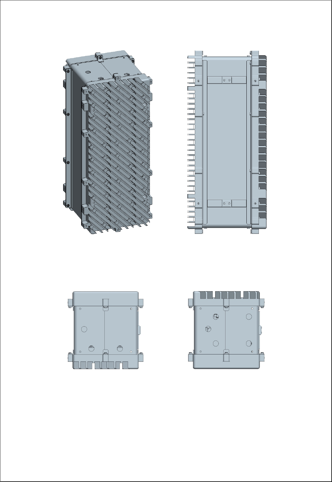
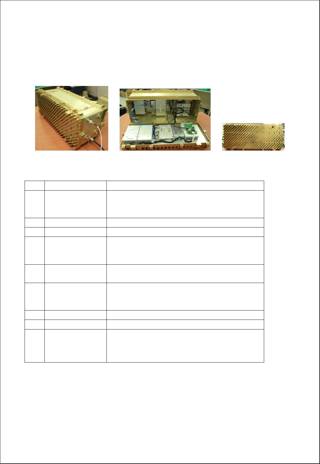
4.2. CM200D01 RU
4.2.1. Mechanical Design
18 / 54
19 / 54
4.2.2. Dimension
RU System picture and Size 127(H) X 559(W) X 211(D) mm
[Side] [Inner Side] [Front/Rear Side]
4.2.3. Mechanical Specification
No Item Description
1 Dimension & Weight
1. Dimension: 127(H) X 559(W) X 211(D) mm
(plinth included)
2. Weight: TBD Kg
2 Method of Cooling Natural convection (Heat-sink)
3 Door Locking Type 10 on each side using bolt lock
4 Optic Connector
1. Position: Cabinet inside
2. Connector type: FC/APC
* Optic cable tray is provided inside of cabinet.
5 ANT PORT 1. located at the bottom side of cabinet
2. Connector Type: N Type Female
6 Power Input
1. Power: TBD
2. Position: bottom side of cabinet
3. Connector: TBD
7 Ground TBD
8 Waterproof condition IP65 compliant
9 Misc. Features
1. Easy to maintain
2. Pole mountable (i.e., telegraph pole)
3. Torque hinge used

20 / 54
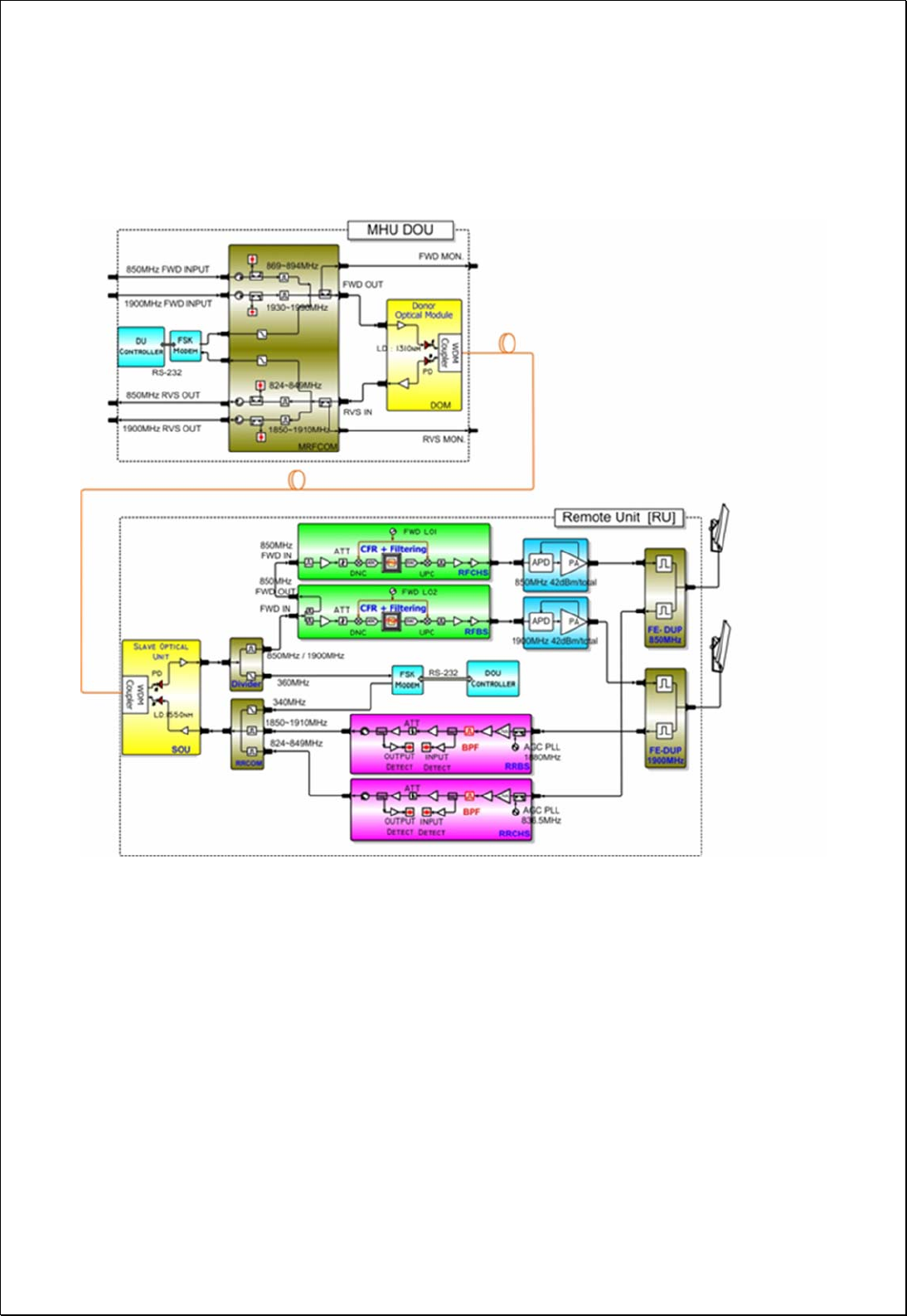
4.2.4. Description of CM200D01 RU
[Forward path]
The RF and modem combined signals sent from the optic module of MHU is first
divided into RF and modem signals at Divider in RU, then the 1900MHz Tx RF signal is
amplified and filtered at the RFBS module, 850MHz Tx RF signal is amplified and
filtered at the RFCHS module. The modem signal is conveyed to CPU of NMS controller
through FSK modem. WCDMA signal is reduced by the Crest Factor passing through
the CFR FPGA digital board inside RFBS and RFCHS. This technology enables reduction
of PAPR for WCDMA signal increasing HPA efficiency. A higher efficiency HPA allows
using a smaller enclosure with lower power consumption while decreasing OPEX for
the service provider.
The GSM and WCDMA RF signals from the RFBS module is linearly amplified up to
high power level on HPA, passed through the Front-End Filter Unit, and finally
transmitted through an antenna.
[Reverse Path]
GSM and WCDMA Rx signals incoming from 1900MHz or 850MHz antenna are first
passed by the Front-End Filter Unit, amplified by a low noise and high gain amplifier,
filtered in RRBS(for 1900MHz band) or RRCHS(for 850MHz band), and combined with
modem signal at combiner(RRCOM). The combined signal is then transmitted to MHU
through the optic module.
21 / 54
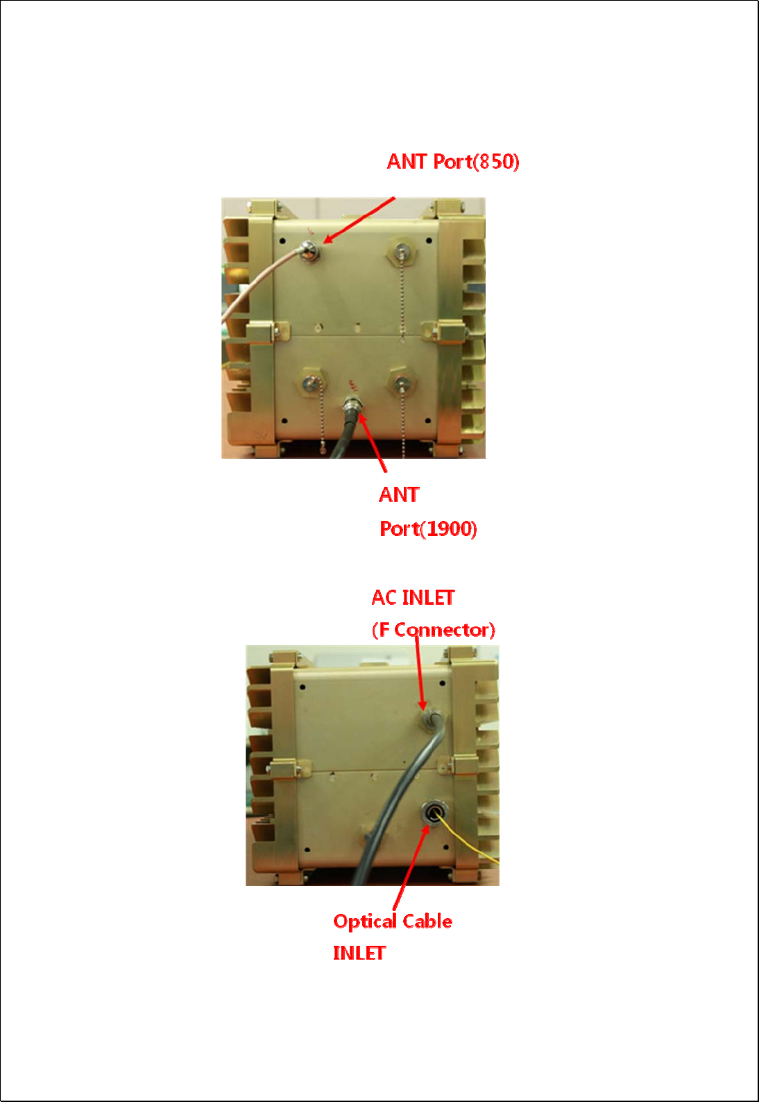
4.2.5. Port Configuration
22 / 54
No Item Description
1 AC INLET Square wave AC Power Cable Connection Port
2 1900MHz ANT Port 1900MHz Band ANT RF Cable Connection Port
3 850MHz ANT Port 850MHz Band ANT RF Cable Connection Port
4 1900MHz Monitor Port Monitor port coupled by -40dB relative to the output power of the
1900MHz ANT Port (Inside)
5 850MHz Monitor Port Monitor port coupled by -40dB relative to the output power of the
850MHz ANT Port (Inside)
6 Optical Cable INLET Optic cable connection Inlet
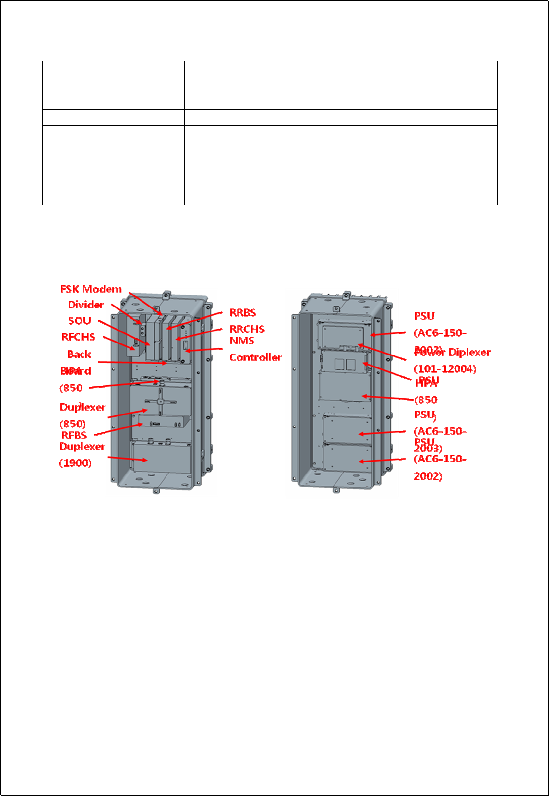
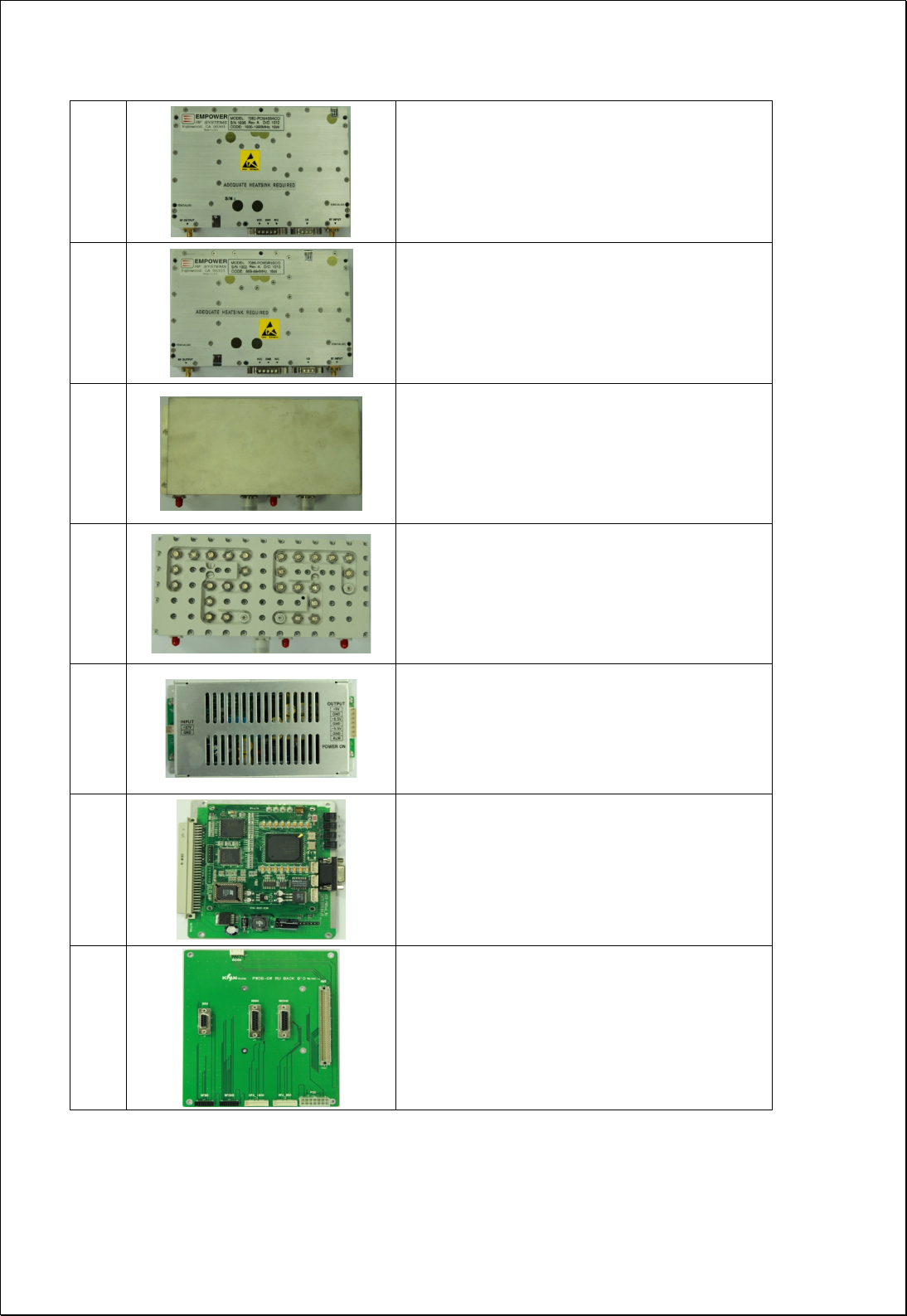
4.2.6. Module Composition of RU

23 / 54
Module operational voltage table
No Module Voltage Used Remarks
1 Divider
2 RF FWD Band Selector for 1900MHz (RFBS) 6.5Vdc
3 RF FWD Channel Selector for 850MHz (RFCHS) 6.5Vdc
4 Slave Optical Transceiver Unit (SOU) 6.5Vdc
5 RF Modem (FSK Modem) 9Vdc
6 RU RVS COM for Signal combing (RRCOM)
7 RU RVS Band Selector for 1900MHz (RRBS) 6.5Vdc
8 RU RVS Band Selector for 850MHz (RRCHS) 6.5Vdc
9 HPA for 1900MHz 29Vdc
10 HPA for 850MHz 29Vdc
11 FE-Duplexer(Front-End Filter Unit) for 1900MHz
12 FE-Duplexer(Front-End Filter Unit) for 850MHz
10 PSU TBD
11 NMS Controller 9Vdc
12 Back Board Ass’y 6.5Vdc / 9Vdc
24 / 54
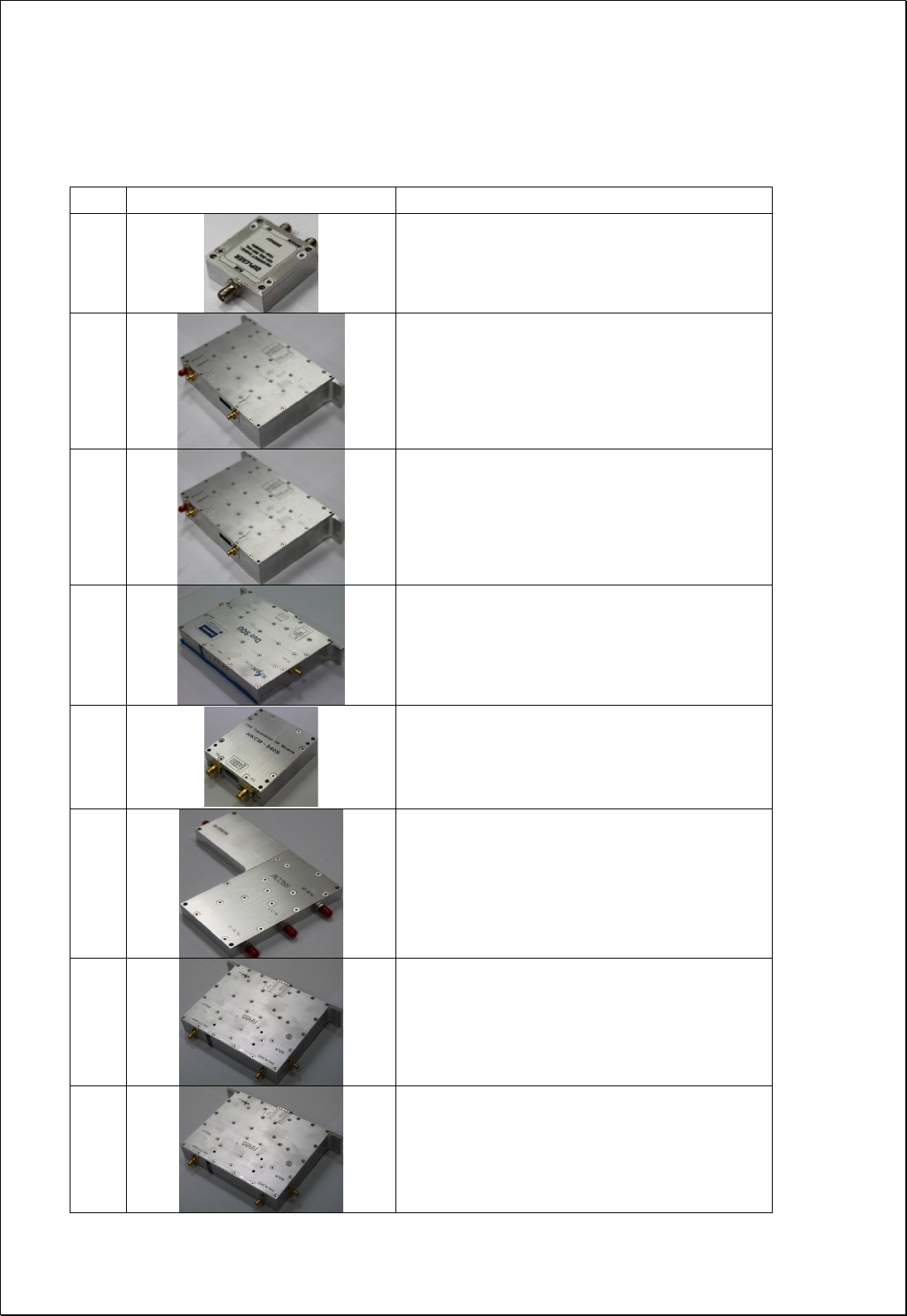
4.2.7. Function of Modules
No Module Description
1
[Divider]
Divides signals into RF and modem signals and
sends to RFBS/RFCHS and FSK modem.
2
[RFBS]
Controls the gain of 1900MHz FWD path, filters
FWD band, controls the crest factor of 1900MHz
FWD signal, and performs the ALC function.
Output of the module is sent to 1900MHz HPA.
3
[RFCHS]
Controls the gain of 850MHz FWD path, filters
FWD band, controls the crest factor of 850MHz
FWD signal, and performs the ALC function.
Output of the module is sent to 850MHz HPA.
3
[SOU]
Performs E/O (or O/E) conversion for FWD and
RVS signals.
Wavelength: TX 1550[nm], RX 1310[nm]
4
[FSK Modem]
Data modem for RU and MHU communication
RU → MHU frequency: 340MHz
MHU → RU frequency: 360MHz
5
[RRCOM]
Combines RVS 850MHz, 1900MHz and Modem
signals, and provides the combined signal to
optical module in order to perform E/O
conversion.
6
[RRBS]
Amplifies RVS 1900MHz signal by low noise high
gain, filters for the desirable band and controls
the RVS path gain of RU.
6
[RRCHS]
Amplifies RVS 850MHz signal by low noise high
gain, filters for the desirable band and controls
the RVS path gain of RU.
25 / 54
8
[1900MHz HPA]
16Watt(42dBm) High power amplifier that
amplifies the RU 1900MHz signal by linearizer
and sends to RU ANT through the 1900MHz FE-
Duplexer.
8
[850MHz HPA]
16Watt(42dBm) High power amplifier that
amplifies the RU 850MHz signal by linearizer and
sends to RU ANT through the 850MHz FE-
Duplexer.
[1900MHz FE-Duplexer]
Front end duplexer that passes through 1900MHz
desired FWD and RVS frequency bands.
9
[850MHz FE-Duplexer]
Front end duplexer that passes through 850MHz
desired FWD and RVS frequency bands.
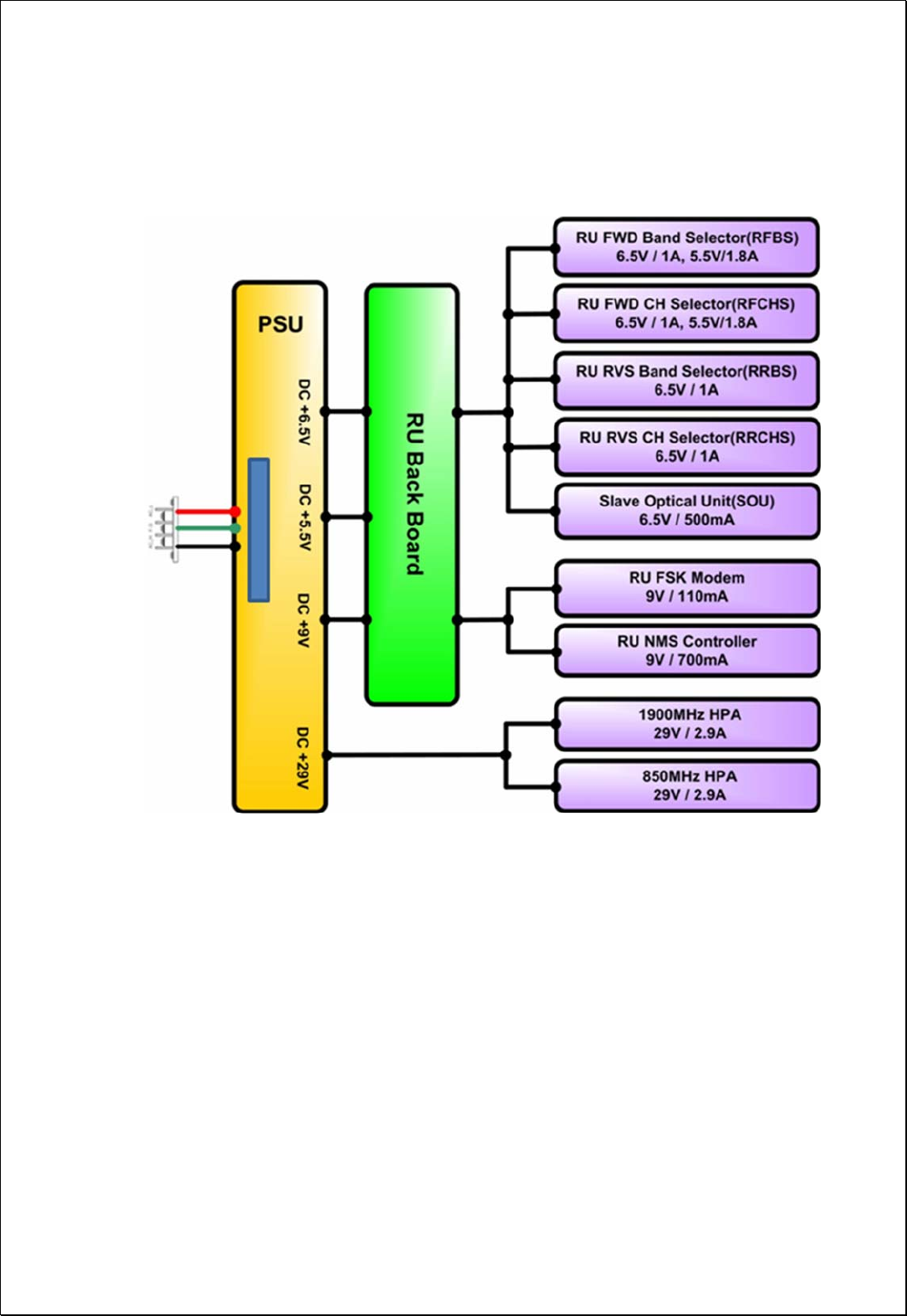
10
[PSU]
Converts DC TBD V to DC 29V/9V/6.5V/5.5V, and
distributes the necessary power to each modules.
11
[NMS Controller]
Monitors the status of modules in RU and
controls the configurable parameters of the RU
modules.
12
[Interface BD]
Provides operating voltage and monitors/controls
signal to modules connected to interface B’D.
Also provides a connection port to communicate
with NMS B’D.
26 / 54
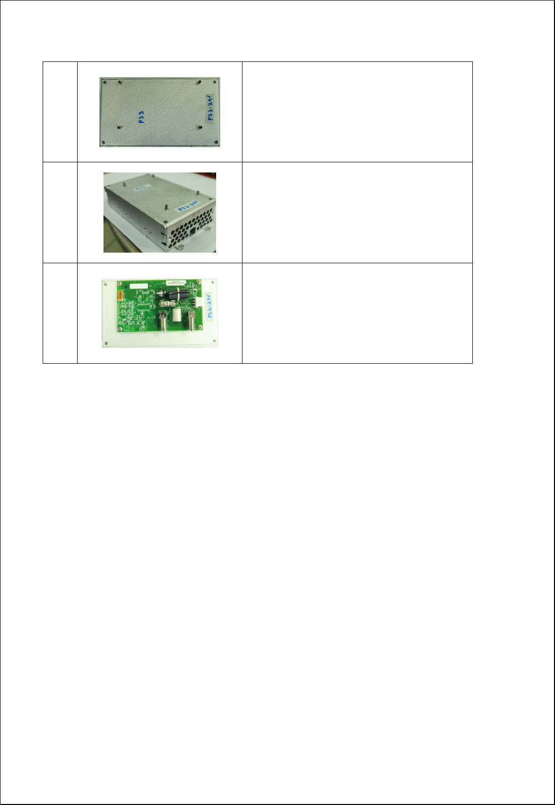
[PSU]
Converts SQAC to DC 29V
[PSU]
Converts SQAC to DC 12V
[Power Diplexer]
Divide SQAC input
27 / 54
Power Distribution Diagram
28 / 54
5. Block Diagram
29 / 54
6. Administration Program (RptMan-PWDUAL)
Administration program (RptMan-PWDUAL) is a management program for CM200D01 and
provides status monitoring and controlling functions to users.
6.1. System Requirement
System: Desktop or laptop PC
OS: Windows XP or later version
Resolution: 1024 768 or more
Connection Cable: 9 pin serial cable (cross type)
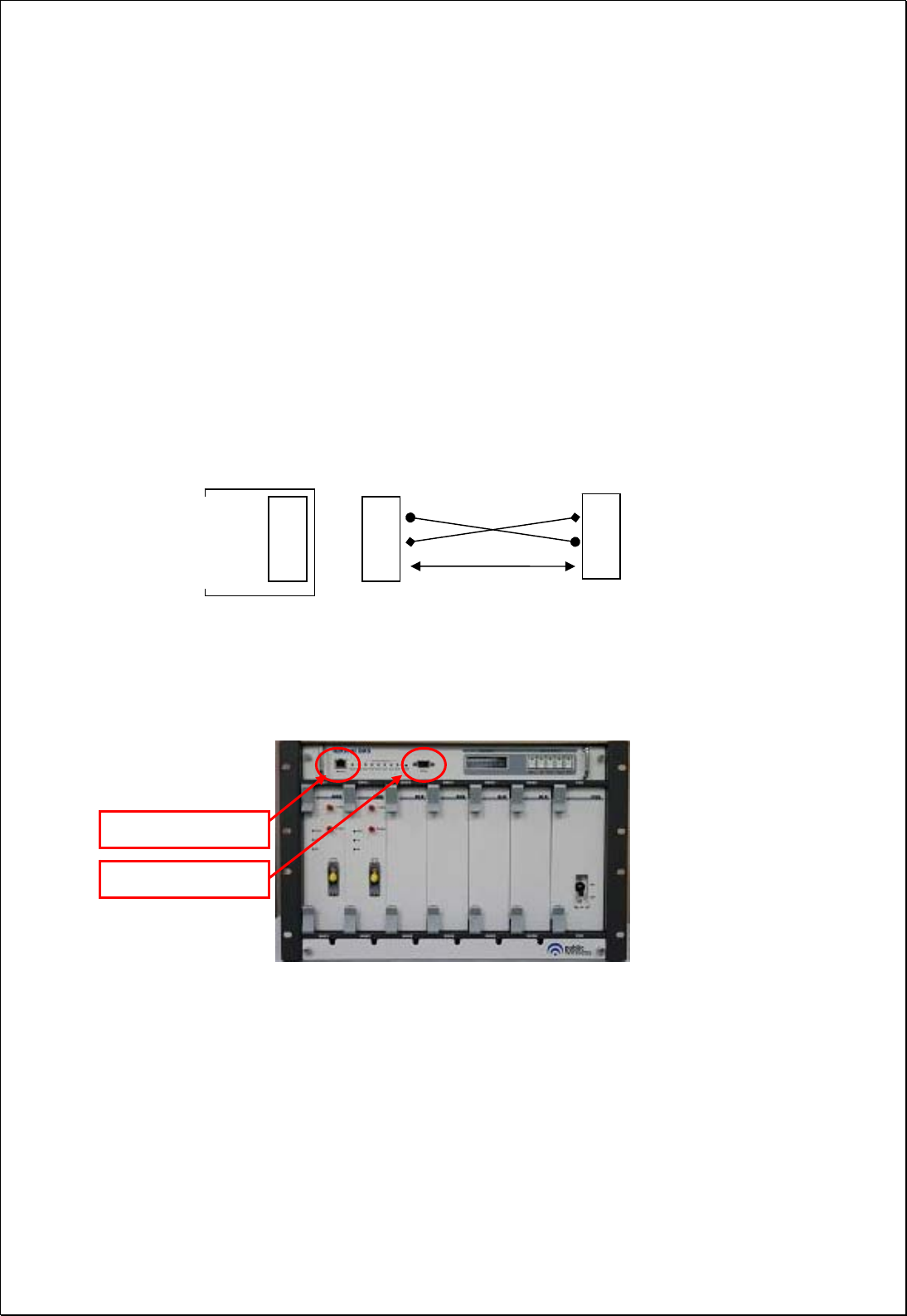
6.2. Cable connection
The cable connection between repeater and PC (GUI program) is illustrated below.
The NMS port of MHU provides two ports; one is a D-sub port for local GUI. The other
is an Ethernet port for NOC (Network Operating Center).
Repeater
NMS
port
D-Sub 9Pin
Female
2
3
5
D-Sub 9Pin Male
2
3
5
D-Sub 9Pin Female
PC GUI
Program
2
3
5
Ethernet port for NOC
D-sub port for GUI
30 / 54
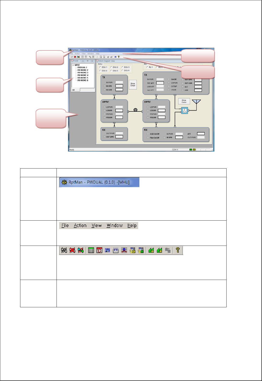
6.3. Screen
Section Description
Window Title
Displays the name of management program(GUI), i.e. RptMan-
PWDUAL.
Displays the type of equipment currently connected to the program
(MHU or RU).
Menu Bar
Presents working menu for operators.
It is associated with tool icons, which can activate the tool bar menus.
Toolbar
Presents icons (button type) for frequently used commands.
User-friendly icons are used.
Icons are activated or disabled as to the status of repeater.
Work Space
Status information and control functions are provided with a block
diagram view of MHU and RU.
Provides the working space for windows or dialogs.
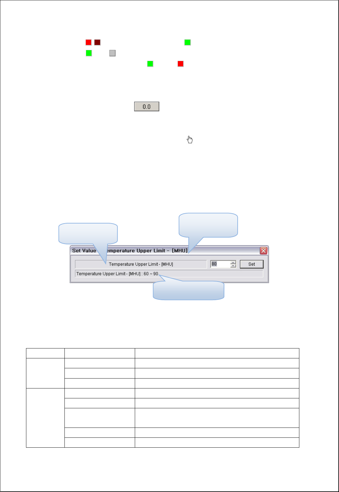
6.4. Status Display
Status of repeater is displayed by LED’s and values.
LED
Work Space
Title Menu Bar
Toolbar
Node Tree
31 / 54
Alarm: / blinking indicates ALARM, indicates NORMAL
On/Off: ON, OFF
Exception) for HPA, is ON, is OFF
Value
Units are not displayed.
Value displayed in box ( )
Control
The shape of mouse cursor is changed to on controllable parameters.
The texts of controllable LED or values are displayed in BOLD font.
6.5. Control Policy
System parameter can only be controlled one at a time.
Click a control item (button) to bring up a control popup dialog window.
Once a dialog popup window is opened, it stays there for repeated control until user
closes the window.
6.6. Menu
Menu Sub Menu Function
Connect Establishes connection between PC(GUI) and repeater
Disconnect Disconnects connection between PC(GUI) and repeater
File
Exit Finishes admin program.
Power Table Presents RF/Optic power table
TC Table Presents temperature compensation table
Image Compression Compress the firmware file (executable file of repeater)
for download
MHU image download Downloads compressed firmware file to MHU equipment
Action
RU image download Downloads compressed firmware file to RU equipment
Showing a control range
Configurable Item
Targe t E qui pm ent.
(MHU or RU)
32 / 54
Factory Setting Restores all parameter values to initial factory settings
System action Not available
Gain Setting
Tx: set ATT to have 35dBm on the remote ANT output.
Rx: set ATT to have 40dB of Rx total gain from RU to
MHU including optical loss.
Polling period Controls the polling period between PC and repeater
Block window Presents system window including MHU and RU
MHU Window Presents MHU status window in work space
View
RU Remote Window Presents RU status window in work space
Cascade
Tile Horizon
Cascade or tile horizon arrangement of repeater status
windows in work space
Arrange icons Arrange all icons under many window is opened
Close all Close all window
Window
Packet Debug Presents debug window in workspace displaying packets
between repeater and GUI program
Help About RptMan.Dual Displays the version information of GUI program, RptMan
(Repeater Manager)
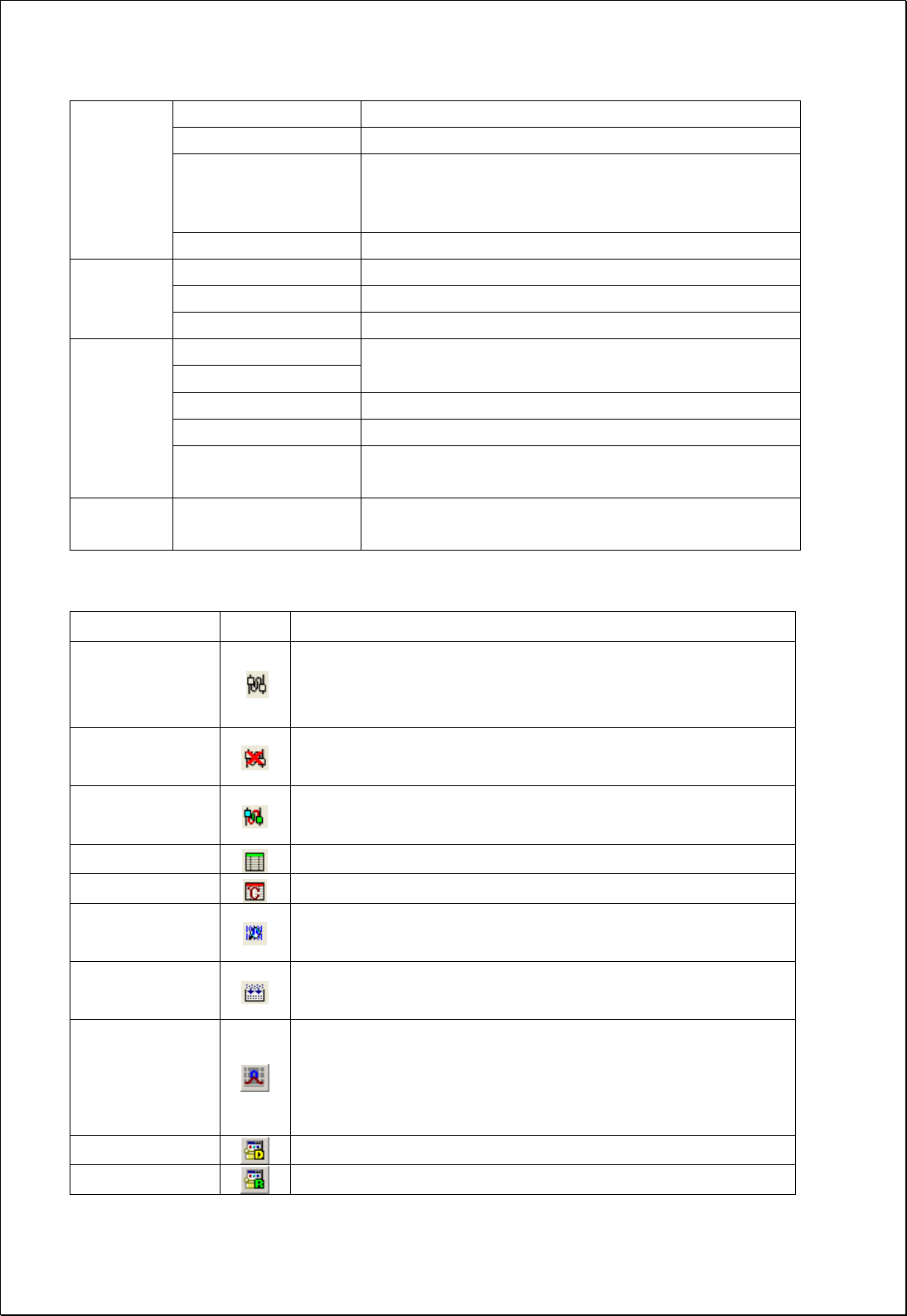
6.7. Toolbar
ITEM ICON Function
Communication
Establishment
Establishes RS-232C connection to the repeater, then GUI
starts to communicate and status of repeater are polled and
displayed.
Communication
Disconnection
Disconnects communication with connected repeater.
Repeater status is not updated.
Polling
Stop/Resume
Stops or resumes polling action of GUI program. (activated
in toggling way)
Power Table Presents RF/Optic power table
T/C table Presents temperature compensation table
Debug Packet
Displays packet data between GUI and repeater like protocol
analyzer and it may help debugging of software
Compression of
image file Compresses image file of repeater
Gain Setting
TX: set ATT to have 35dBm of output at the RU ANT Port
RX: set ATT to have 40dB gain of Rx path
Tx/Rx Gain setting function carry out Tx/Rx gain setting
including optical loss compensation automatically.
MHU Download Download MHU firmware files to MHU equipment.
RU Download Download RU firmware files to RU equipment.
33 / 54
MHU Factory
Setting Initialize MHU parameters to factory setting values.
RU Factory
Setting
Restores RU parameters back to original factory setting
values.
Help Shows version information
6.8. Program operation
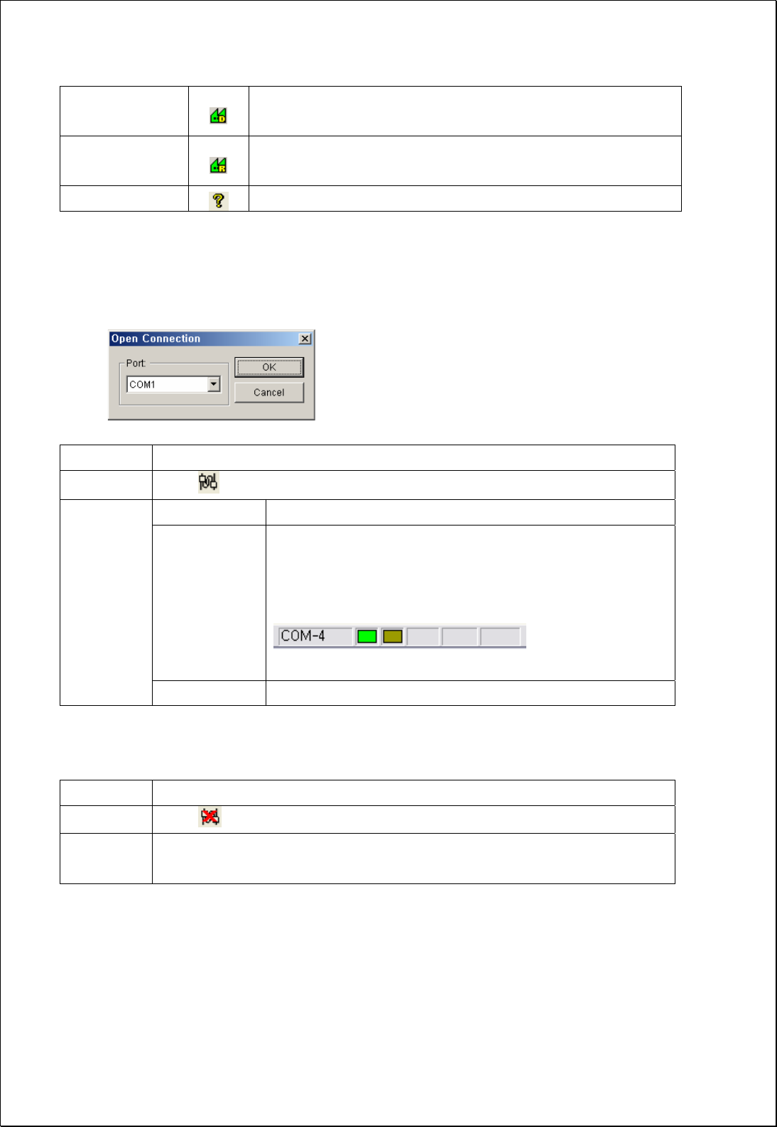
6.8.1. Initiating communication
Function Establishing communication between GUI and repeater
Method Click button in toolbar of GUI program
Port Combo box to set the com port (COM1, COM2, …)
OK Button Initiates communication between GUI and repeater, then
closes this popup window(“Open Connection”)
When communication port is established correctly, you
can see the communication status by blinking icons.
(right-bottom side
of the main screen)
Description
Cancel Button Cancels and closes the popup window
6.8.2. Disconnect
Function Disconnecting GUI from repeater
Method Click button in toolbar of GUI program
Description The communication between GUI on PC and repeater becomes
disconnected.
34 / 54
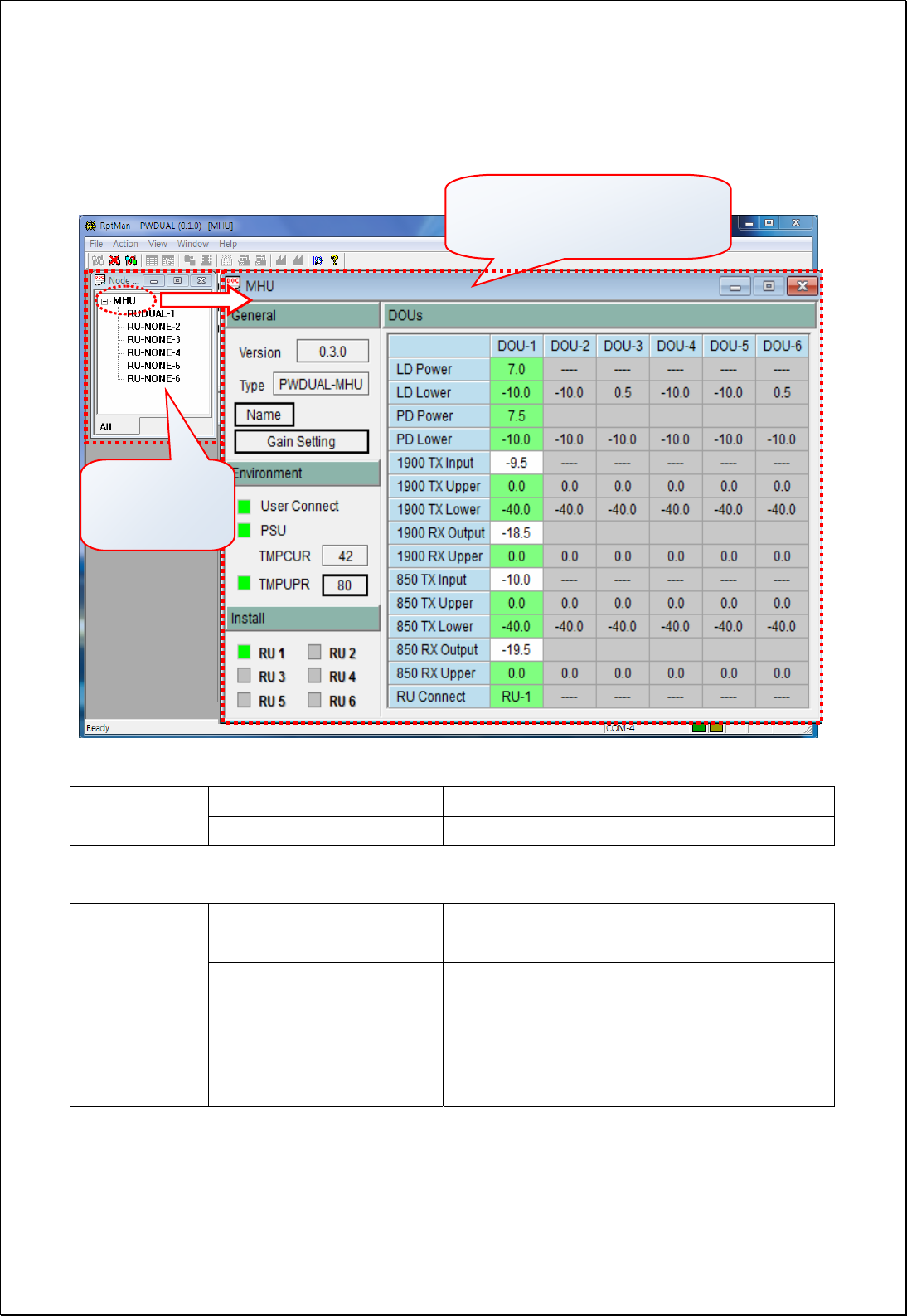
6.8.3. CM200D01 MHU Status Retrieval and Control
(1) Node Tree: This window displays the tree configuration of RUs connected with MHU
① MHU Press MHU to open the MHU screen
(1) Nose Tree ② RUDUAL-1 ~ 6 Press RUDUAL-# to open each RU screen
(2) MHU Screen window
① General & Environment This part includes common parameter of MHU
like system information or environments
(2) MHU
Screen ② DOU Status/Control
This screen provides information on 6DOUs
LD Power & Lower limit value
PD Power & Lower limit value
Tx Input, Rx Output Power & Limit value
RU Install information
(2) MHU Screen Window
① General & Environment part
②DOU’s Status & Control
p
art
(1) Node Tree
① MHU
② RUDUAL-1~6
35 / 54
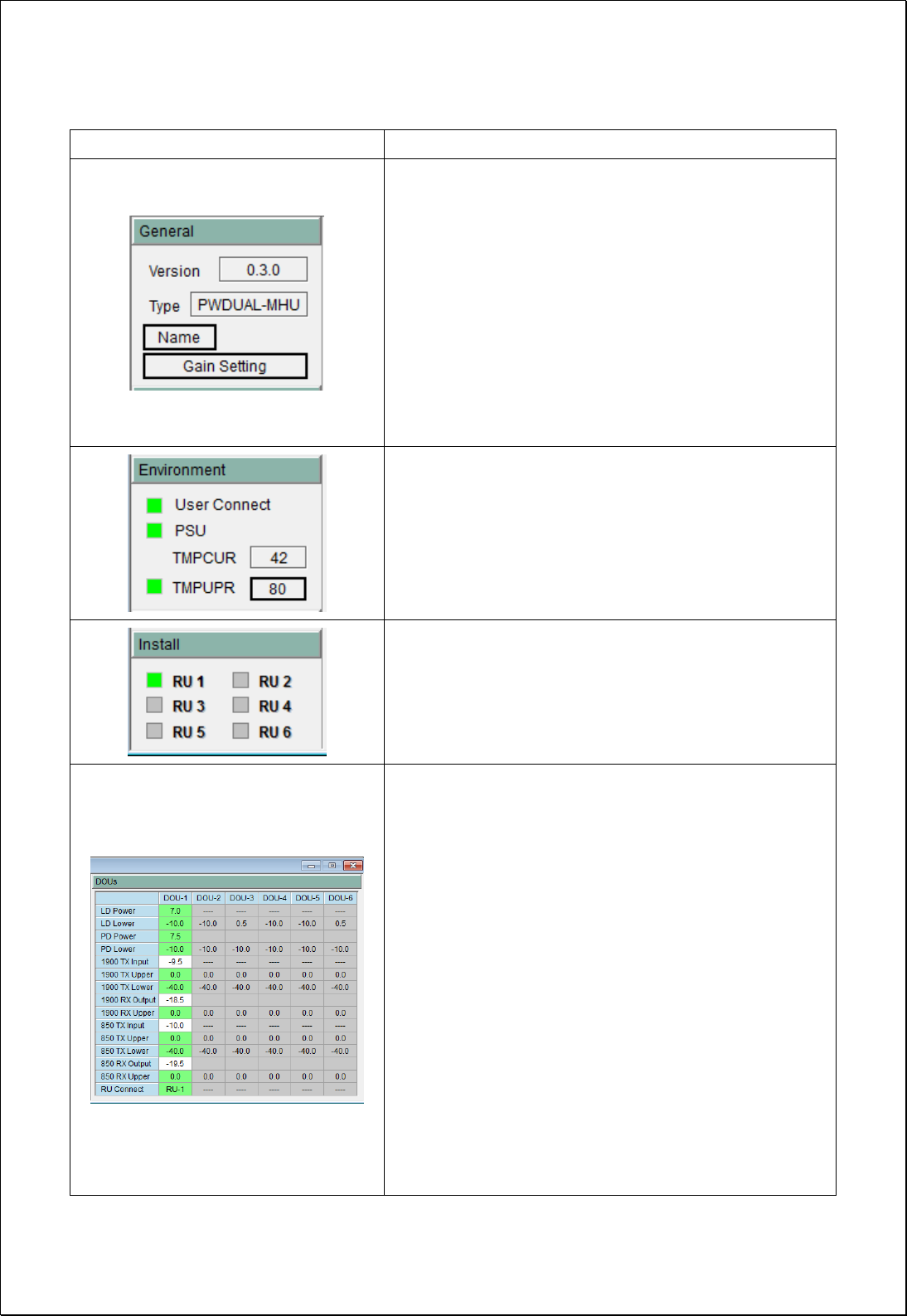
Group Description
Version: Firmware Versoin
Type: Repeater unit type
Name: ID of MHU for the communication
Gain Setting
TX: sets ATT to have 35dBm of output at the RU
ANT Port
RX: sets ATT to have 40dB gain of Rx path
Tx/Rx Gain setting function carries out Tx/Rx
gain setting including automatic optical loss
compensation.
User Connect: Connection status of COM port of
repeater
PSU: Status of PSU
TMPCUR: Current temperature of the equipment
TMPUPR: set the upper threshold value of
temperature (button) and alarm status (LED)
Install: This sets up the RU to communicate with
MHU. Even when an RU is connected to MHU
physically by optic cable, the RU cannot
communicate with MHU if RU is not installed
logically by GUI.
LD Power: Transmitted optical power level to RU
LD Lower: Lower limit level of the LD power
PD Power: Received optical power level from RU
PD Lower: Lower limit level of the PD power
1900 Tx Input: Tx level input from 1900MHz BTS
1900 Tx Upper: Upper limit of Tx input level
1900 Tx Lower: Lower limit of Tx input level
1900 Rx output: Rx level output to 1900MHz BTS
1900 Rx Upper: Upper limit of Rx output level
850 Tx Input: Tx level input from 850MHz BTS
850 Tx Upper: Upper limit of Tx input level
850 Tx Lower: Lower limit of Tx input level
850 Rx output: Rx level output to 850MHz BTS
850 Rx Upper: Upper limit of Rx output level
RU install: display the RU installation status
36 / 54
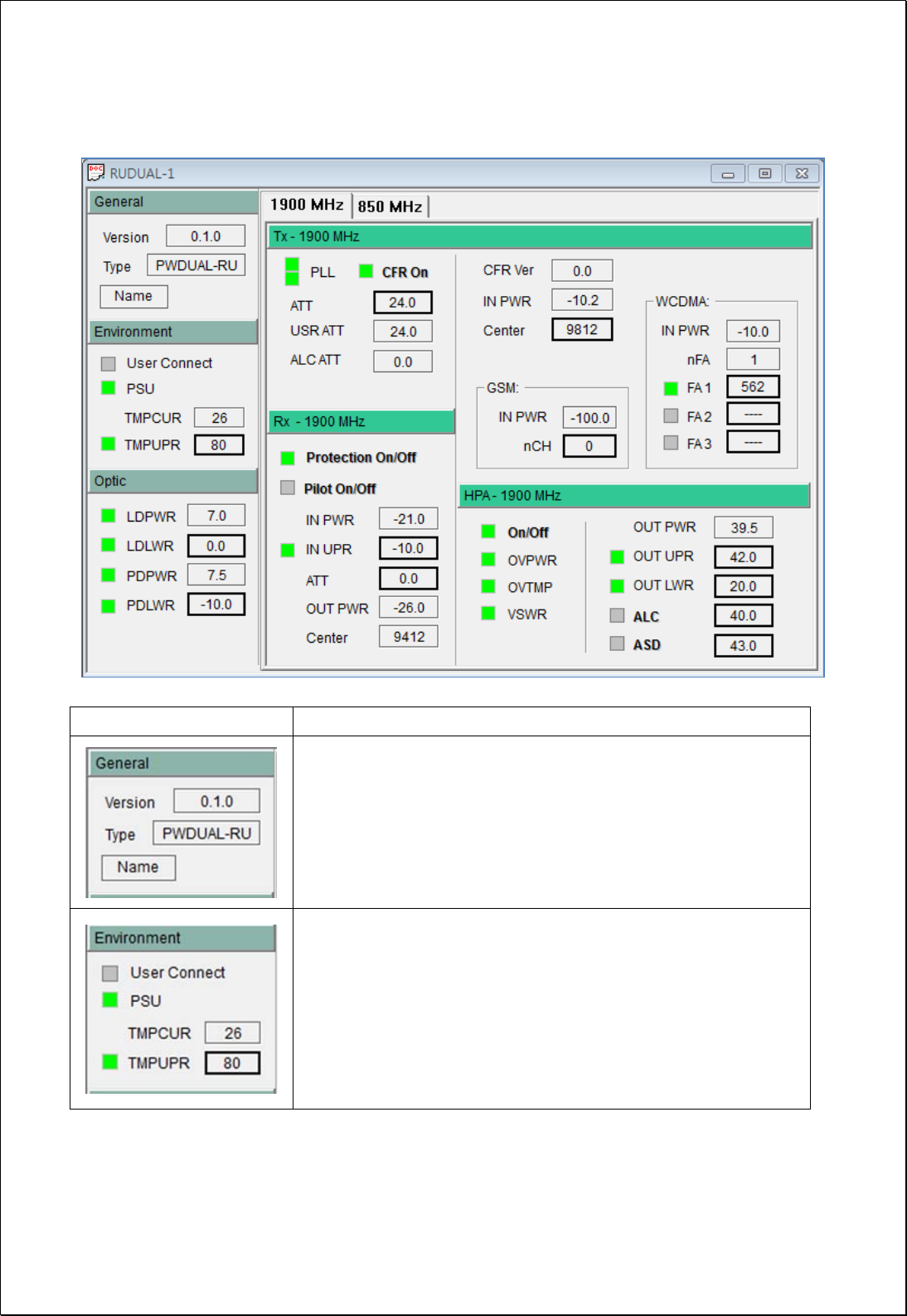
6.8.4. CM200D01 RU Status Retrieval and Control
Group Description
Version: Firmware version
Type: Type of repeater
Name: Set the Name, ID, Serial No. of repeater RU
User Connect: Connection status of COM port of repeater
PSU: Status of PSU
TMPCUR: Current temperature in repeater RU
TMPUPR: Value/control of upper threshold of temperature
(button) and alarm status (LED)
37 / 54
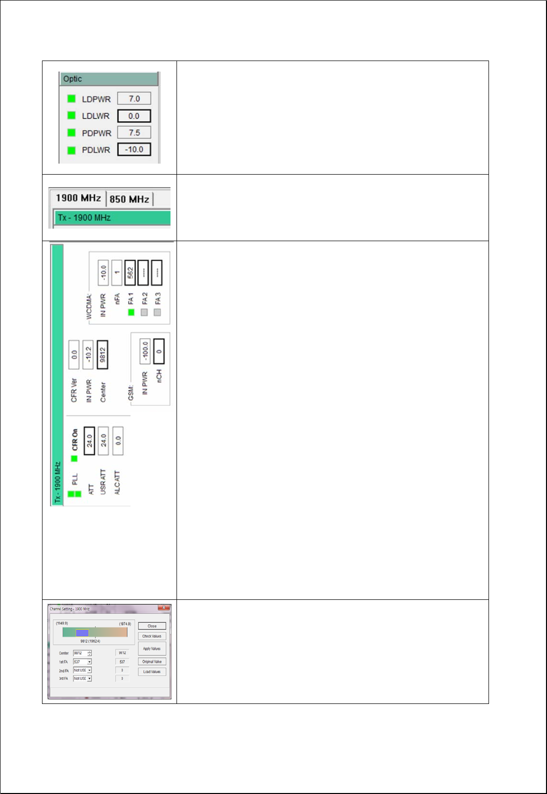
LDPWR: Value of LD power (box) and status of LD (LED)
LDLWR: Value/control of lower threshold of LD power
(button) and lower alarm status of LD power (LED)
PDPWR: Value of PD power (box) and status of PD (LED)
PDLWR: Value/control of lower threshold of PD power
(button) and lower alarm status (LED)
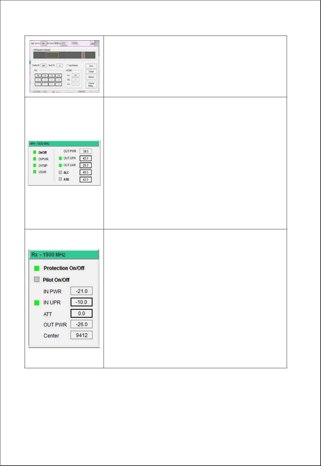
RU parameters for 1900MHz/850MHz band are displayed
by the tab selection. Each band has the identical items
which can be monitored and controlled.
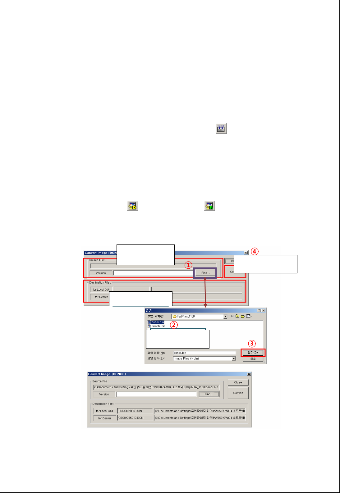
PLL: Alarm LED for 2 PLL’s
CFR On: On/Off status of Crest Factor Reduction function
ATT: Sets ATT to control FWD gain, and shows its value.
Displayed ATT value = USR ATT + ALC ATT
USR ATT: This is the main FWD Gain setting point. It is used
for FWD auto gain setting or gain fine tuning
ALC ATT: When HPA output level is higher than ALC level it
automatically controls FWD gain to maintain output level
below HPA ALC level.
CFR On: On/Off control the Crest factor reduction function
INPWR: Input total power level on CFR board
Center: Set the center frequency of FWD band by GSM CH
No.
GSM INPWR: This indicates signal power of GSM
GSM nCH: Indicates the current no. of GSM CH. When
pressed, more information about GSM CHs can be viewed.
WCDMA INPWR: Indicates signal power of WCDMA
WCDMA nFA: Indicates the current no. of WCDMA FA
WCDMA FA1/FA2/FA3: This is to set the WCDMA CH to
apply the CFR function to WCDMA FA’s.
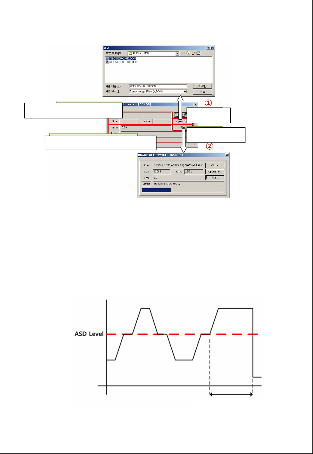
Channel Setting Window for WCDMA CH and band center
Center: 25MHz operating band center frequency setting
1st~3rd FA: WCDMA FA setting for WCDMA CFR function
Apply Values: setting action for Center and WCDMA CH
Load Values: verification action for set valuses after setting
the Center and WCDMA CH
38 / 54
GSM Spectrum View Window
Center CH: GSM CH for center freq. of 25MHz band
Num CH: Number of GSM CH currently dectected
FAs: GSM CH of spectrum displayed “GSM spectrum
detected” window
WCDMA FA1~FA3: Currently set WCDMA FA CH.
On/Off: Status/control the operation state of HPA
OVTMP: Alarm status of HPA Over-temperature
OVPWR: Alarm status of HPA Over-Power
VSWR: Alarm status of HPA VSWR
OUT PWR: Output power level of HPA(box)
OUT UPR: Display/control of upper threshold of HPA output
power(button), alarm status(LED)
OUT LWR: Value/control of lower threshold of HPA output
power(button), alarm status(LED)
ALC: Set ALC level for HPA output, and shows ALC on/off
status of function(LED).
ASD(Auto Shutdown): ASD level(button), and shows ASD
on/off status of function(LED).
Protection On/Off: In order to protect RU from over input
RVS(Rx) signal power. In case that input signal is more than
IN UPR level, RU shuts down and LED is changed to RED.
Pilot On/Off: Sets CW signal generation, and shows its
status. It is used for RVS gain setting.
IN PWR: RVS power value at the LNA output point
IN UPR: Sets RVS input upper threshold, and shows the
alarm status of input upper threshold.
OUTPWR: RVS RF output power of RRBS(RRCHS)
ATT: Sets ATT to control RVS gain, and shows it’s value.
Center Freq: It indicates pilot signal frequency value. This
value changes with FWD(Tx) center frequency automatically.
39 / 54
6.8.5. Firmware download
Firmware download is performed when system needs to be updated.
Downloading improper images (executable file of repeater CPU) may cause harmful
damages to equipment.
The following steps should be taken for firmware download.
① Convert firmware source file (*.bin) to a downloadable file format.
Main menu: Action → Image Compression, toolbar:
② Open a pop-up window showing the status of the target equipment for firmware
download.
Step 1) Main menu View ¡æ Select Donor Windows or Remote Windows
Step 2) In Block View Dialog window, select Donor Windows or Remote Windows
③ Download firmware to the target equipment.
Step 1) Main menu Action ¡æ select Image Download menu
Step 2) In toolbar, select for MHU, and select for RU
Download firmware after selecting the firmware file for the target equipment.
File conversion procedure
Select target file
Perform function
Store modified
Select target file
40 / 54
Download procedure
6.9. Additional features
6.9.1. ASD (Auto Shutdown) Function
1. If the power level is above the shut down level for longer than 1 second, turn off
HPA.
2. During shutdown state, monitor RU input power. If the level is below 5dB from shut
down level, turn on HPA automatically.
3. Monitor HPA output power in normal operation, and monitor RU input power during
shut down.
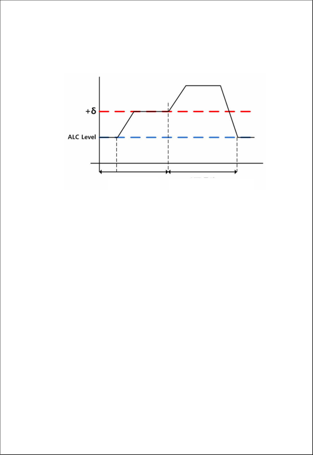
6.9.2. ALC (Auto Level Control) Function
Display selected file information
Display progress of firmware download
Select file
Perform operation
Longer than 1 sec, HPA off
41 / 54
1. If the power level reaches the ALC level, prevent from transmitting higher than ALC
level by using ATT control.
2. By storing the existing ATT value, the ATT value before ALC can be reused even
when the power is reduced.
No ATT change ATT increase(Gain decrease)

42 / 54
Appendix A Factory setting value for each equipment
MHU RU
Item Value Item Value
MHU TEMP UPR 80 RU TEMP UPR 80
1900/850MHz Tx IN UPR 0 RFBS, RFCHS ATT 30
1900/850MHz Tx IN LWR -10 Hidden ATT N.A
1900/850MHz Rx OUT UPR 0 PLL N.A
Optic LD LWR 0 - N.A
Optic PD LWR -10 HPA-850, HPA-1900 On/off Off
HPA-850, HPA-1900 OUT UPR 42
HPA-850, HPA-1900 OUT LWR 20
HPA-850, HPA-1900 ALC Level 40
HPA-850, HPA-1900 ALC On/Off ON
HPA-850, HPA-1900 ASD Level 43
HPA-850, HPA-1900 ASD On/Off ON
RRBS, RRCHS ASD ON
RRBS, RRCHS IN UPR -50
RRBS, RRCHS ATT 30
RRBS, RRCHS PLL N.A
Optic LD LWR 0
Optic PD LWR -10
43 / 54
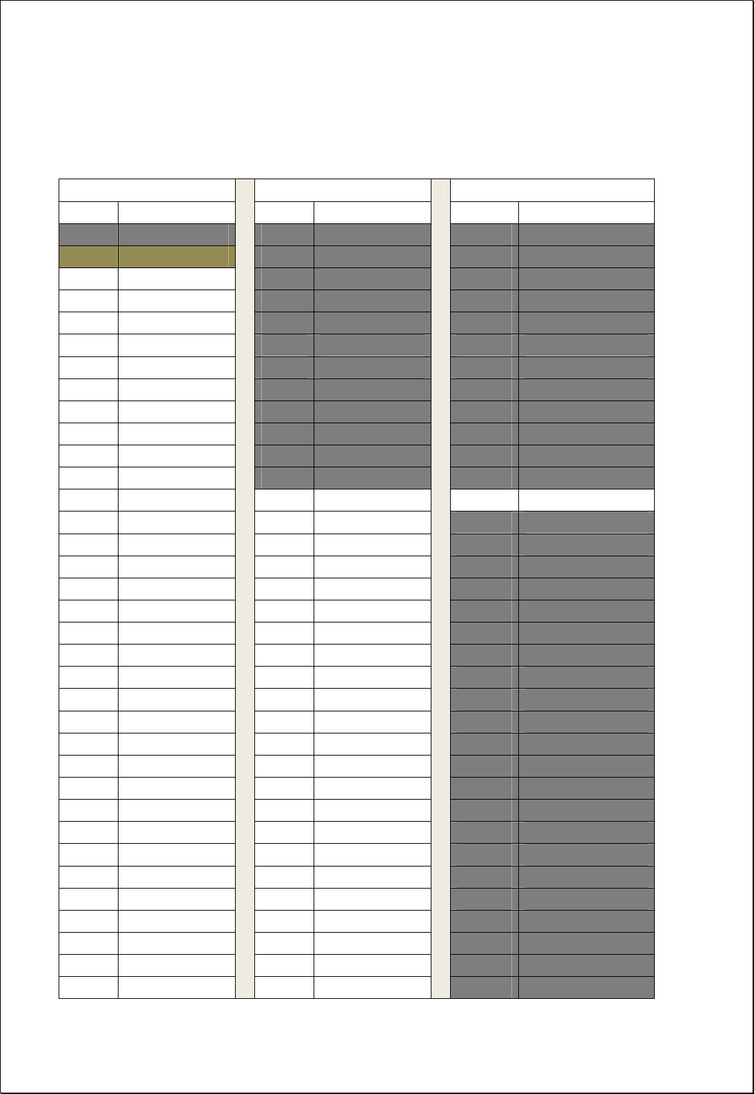
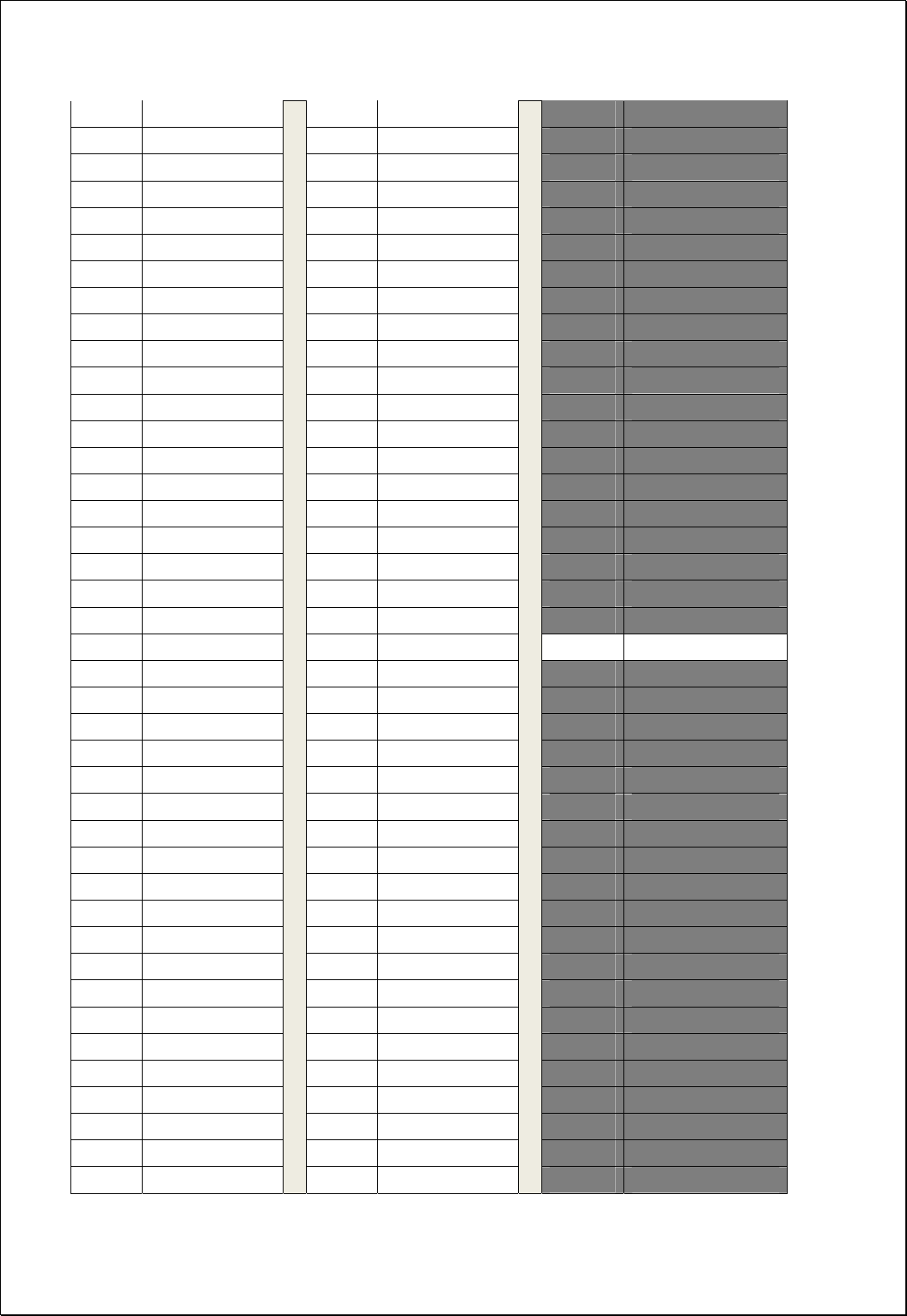
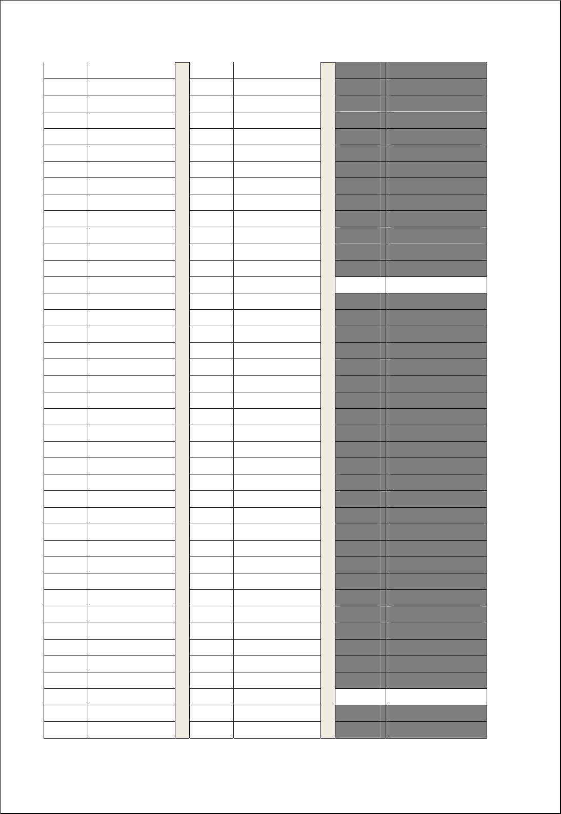
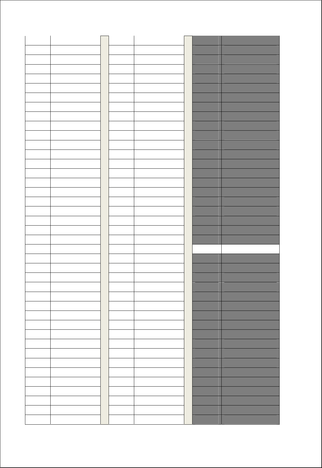
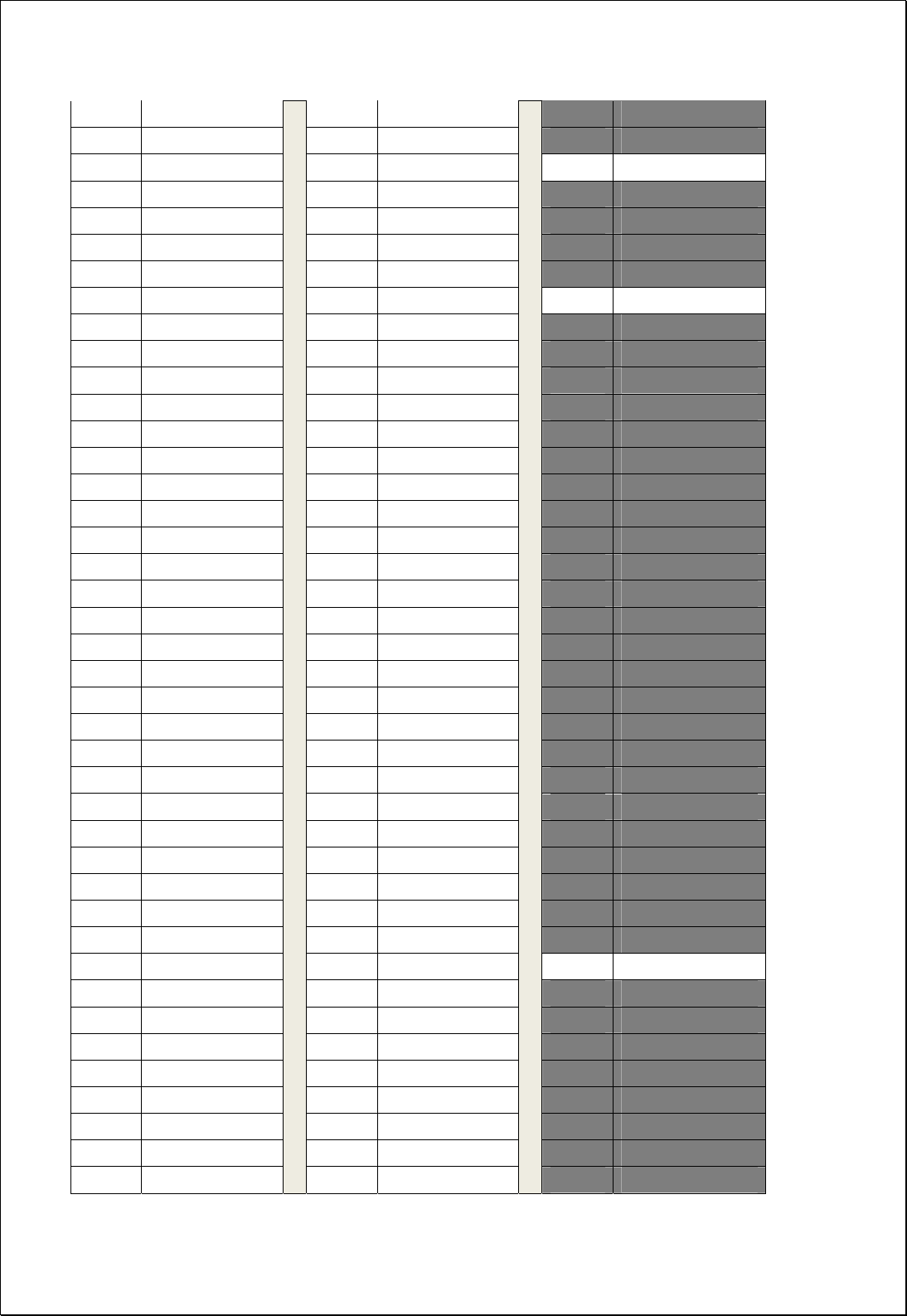
Appendix B 1900MHz GSM & WCDMA Frequency Map
Gray Channels are not used
GSM WCDMA WCDMA
Channel Center freq.(MHz) Channel Center freq.(MHz) Channel Center freq.(MHz)
511 1930.0 9650 1930.0 400 1930.1
512 1930.2 9651 1930.2 401 1930.3
513 1930.4 9652 1930.4 402 1930.5
514 1930.6 9653 1930.6 403 1930.7
515 1930.8 9654 1930.8 404 1930.9
516 1931.0 9655 1931.0 405 1931.1
517 1931.2 9656 1931.2 406 1931.3
518 1931.4 9657 1931.4 407 1931.5
519 1931.6 9658 1931.6 408 1931.7
520 1931.8 9659 1931.8 409 1931.9
521 1932.0 9660 1932.0 410 1932.1
522 1932.2 9661 1932.2 411 1932.3
523 1932.4 9662 1932.4 412 1932.5
524 1932.6 9663 1932.6 413 1932.7
525 1932.8 9664 1932.8 414 1932.9
526 1933.0 9665 1933.0 415 1933.1
527 1933.2 9666 1933.2 416 1933.3
528 1933.4 9667 1933.4 417 1933.5
529 1933.6 9668 1933.6 418 1933.7
530 1933.8 9669 1933.8 419 1933.9
531 1934.0 9670 1934.0 420 1934.1
532 1934.2 9671 1934.2 421 1934.3
533 1934.4 9672 1934.4 422 1934.5
534 1934.6 9673 1934.6 423 1934.7
535 1934.8 9674 1934.8 424 1934.9
536 1935.0 9675 1935.0 425 1935.1
537 1935.2 9676 1935.2 426 1935.3
538 1935.4 9677 1935.4 427 1935.5
539 1935.6 9678 1935.6 428 1935.7
540 1935.8 9679 1935.8 429 1935.9
541 1936.0 9680 1936.0 430 1936.1
542 1936.2 9681 1936.2 431 1936.3
543 1936.4 9682 1936.4 432 1936.5
544 1936.6 9683 1936.6 433 1936.7
545 1936.8
9684 1936.8 434 1936.9

44 / 54
546 1937.0 9685 1937.0 435 1937.1
547 1937.2 9686 1937.2 436 1937.3
548 1937.4 9687 1937.4 437 1937.5
549 1937.6 9688 1937.6 438 1937.7
550 1937.8 9689 1937.8 439 1937.9
551 1938.0 9690 1938.0 440 1938.1
552 1938.2 9691 1938.2 441 1938.3
553 1938.4 9692 1938.4 442 1938.5
554 1938.6 9693 1938.6 443 1938.7
555 1938.8 9694 1938.8 444 1938.9
556 1939.0 9695 1939.0 445 1939.1
557 1939.2 9696 1939.2 446 1939.3
558 1939.4 9697 1939.4 447 1939.5
559 1939.6 9698 1939.6 448 1939.7
560 1939.8 9699 1939.8 449 1939.9
561 1940.0 9700 1940.0 450 1940.1
562 1940.2 9701 1940.2 451 1940.3
563 1940.4 9702 1940.4 452 1940.5
564 1940.6 9703 1940.6 453 1940.7
565 1940.8 9704 1940.8 454 1940.9
566 1941.0 9705 1941.0 455 1941.1
567 1941.2 9706 1941.2 456 1941.3
568 1941.4 9707 1941.4 457 1941.5
569 1941.6 9708 1941.6 458 1941.7
570 1941.8 9709 1941.8 459 1941.9
571 1942.0 9710 1942.0 460 1942.1
572 1942.2 9711 1942.2 461 1942.3
573 1942.4 9712 1942.4 462 1942.5
574 1942.6 9713 1942.6 463 1942.7
575 1942.8 9714 1942.8 464 1942.9
576 1943.0 9715 1943.0 465 1943.1
577 1943.2 9716 1943.2 466 1943.3
578 1943.4 9717 1943.4 467 1943.5
579 1943.6 9718 1943.6 468 1943.7
580 1943.8 9719 1943.8 469 1943.9
581 1944.0 9720 1944.0 470 1944.1
582 1944.2 9721 1944.2 471 1944.3
583 1944.4 9722 1944.4 472 1944.5
584 1944.6 9723 1944.6 473 1944.7
585 1944.8 9724 1944.8 474 1944.9
586 1945.0 9725 1945.0 475 1945.1

45 / 54
587 1945.2 9726 1945.2 476 1945.3
588 1945.4 9727 1945.4 477 1945.5
589 1945.6 9728 1945.6 478 1945.7
590 1945.8 9729 1945.8 479 1945.9
591 1946.0 9730 1946.0 480 1946.1
592 1946.2 9731 1946.2 481 1946.3
593 1946.4 9732 1946.4 482 1946.5
594 1946.6 9733 1946.6 483 1946.7
595 1946.8 9734 1946.8 484 1946.9
596 1947.0 9735 1947.0 485 1947.1
597 1947.2 9736 1947.2 486 1947.3
598 1947.4 9737 1947.4 487 1947.5
599 1947.6 9738 1947.6 488 1947.7
600 1947.8 9739 1947.8 489 1947.9
601 1948.0 9740 1948.0 490 1948.1
602 1948.2 9741 1948.2 491 1948.3
603 1948.4 9742 1948.4 492 1948.5
604 1948.6 9743 1948.6 493 1948.7
605 1948.8 9744 1948.8 494 1948.9
606 1949.0 9745 1949.0 495 1949.1
607 1949.2 9746 1949.2 496 1949.3
608 1949.4 9747 1949.4 497 1949.5
609 1949.6 9748 1949.6 498 1949.7
610 1949.8 9749 1949.8 499 1949.9
611 1950.0 9750 1950.0 500 1950.1
612 1950.2 9751 1950.2 501 1950.3
613 1950.4 9752 1950.4 502 1950.5
614 1950.6 9753 1950.6 503 1950.7
615 1950.8 9754 1950.8 504 1950.9
616 1951.0 9755 1951.0 505 1951.1
617 1951.2 9756 1951.2 506 1951.3
618 1951.4 9757 1951.4 507 1951.5
619 1951.6 9758 1951.6 508 1951.7
620 1951.8 9759 1951.8 509 1951.9
621 1952.0 9760 1952.0 510 1952.1
622 1952.2 9761 1952.2 511 1952.3
623 1952.4 9762 1952.4 512 1952.5
624 1952.6 9763 1952.6 513 1952.7
625 1952.8 9764 1952.8 514 1952.9
626 1953.0 9765 1953.0 515 1953.1
627 1953.2 9766 1953.2 516 1953.3
46 / 54
628 1953.4 9767 1953.4 517 1953.5
629 1953.6 9768 1953.6 518 1953.7
630 1953.8 9769 1953.8 519 1953.9
631 1954.0 9770 1954.0 520 1954.1
632 1954.2 9771 1954.2 521 1954.3
633 1954.4 9772 1954.4 522 1954.5
634 1954.6 9773 1954.6 523 1954.7
635 1954.8 9774 1954.8 524 1954.9
636 1955.0 9775 1955.0 525 1955.1
637 1955.2 9776 1955.2 526 1955.3
638 1955.4 9777 1955.4 527 1955.5
639 1955.6 9778 1955.6 528 1955.7
640 1955.8 9779 1955.8 529 1955.9
641 1956.0 9780 1956.0 530 1956.1
642 1956.2 9781 1956.2 531 1956.3
643 1956.4 9782 1956.4 532 1956.5
644 1956.6 9783 1956.6 533 1956.7
645 1956.8 9784 1956.8 534 1956.9
646 1957.0 9785 1957.0 535 1957.1
647 1957.2 9786 1957.2 536 1957.3
648 1957.4 9787 1957.4 537 1957.5
649 1957.6 9788 1957.6 538 1957.7
650 1957.8 9789 1957.8 539 1957.9
651 1958.0 9790 1958.0 540 1958.1
652 1958.2 9791 1958.2 541 1958.3
653 1958.4 9792 1958.4 542 1958.5
654 1958.6 9793 1958.6 543 1958.7
655 1958.8 9794 1958.8 544 1958.9
656 1959.0 9795 1959.0 545 1959.1
657 1959.2 9796 1959.2 546 1959.3
658 1959.4 9797 1959.4 547 1959.5
659 1959.6 9798 1959.6 548 1959.7
660 1959.8 9799 1959.8 549 1959.9
661 1960.0 9800 1960.0 550 1960.1
662 1960.2 9801 1960.2 551 1960.3
663 1960.4 9802 1960.4 552 1960.5
664 1960.6 9803 1960.6 553 1960.7
665 1960.8 9804 1960.8 554 1960.9
666 1961.0 9805 1961.0 555 1961.1
667 1961.2 9806 1961.2 556 1961.3
668 1961.4 9807 1961.4 557 1961.5
47 / 54
669 1961.6 9808 1961.6 558 1961.7
670 1961.8 9809 1961.8 559 1961.9
671 1962.0 9810 1962.0 560 1962.1
672 1962.2 9811 1962.2 561 1962.3
673 1962.4 9812 1962.4 562 1962.5
674 1962.6 9813 1962.6 563 1962.7
675 1962.8 9814 1962.8 564 1962.9
676 1963.0 9815 1963.0 565 1963.1
677 1963.2 9816 1963.2 566 1963.3
678 1963.4 9817 1963.4 567 1963.5
679 1963.6 9818 1963.6 568 1963.7
680 1963.8 9819 1963.8 569 1963.9
681 1964.0 9820 1964.0 570 1964.1
682 1964.2 9821 1964.2 571 1964.3
683 1964.4 9822 1964.4 572 1964.5
684 1964.6 9823 1964.6 573 1964.7
685 1964.8 9824 1964.8 574 1964.9
686 1965.0 9825 1965.0 575 1965.1
687 1965.2 9826 1965.2 576 1965.3
688 1965.4 9827 1965.4 577 1965.5
689 1965.6 9828 1965.6 578 1965.7
690 1965.8 9829 1965.8 579 1965.9
691 1966.0 9830 1966.0 580 1966.1
692 1966.2 9831 1966.2 581 1966.3
693 1966.4 9832 1966.4 582 1966.5
694 1966.6 9833 1966.6 583 1966.7
695 1966.8 9834 1966.8 584 1966.9
696 1967.0 9835 1967.0 585 1967.1
697 1967.2 9836 1967.2 586 1967.3
698 1967.4 9837 1967.4 587 1967.5
699 1967.6 9838 1967.6 588 1967.7
700 1967.8 9839 1967.8 589 1967.9
701 1968.0 9840 1968.0 590 1968.1
702 1968.2 9841 1968.2 591 1968.3
703 1968.4 9842 1968.4 592 1968.5
704 1968.6 9843 1968.6 593 1968.7
705 1968.8 9844 1968.8 594 1968.9
706 1969.0 9845 1969.0 595 1969.1
707 1969.2 9846 1969.2 596 1969.3
708 1969.4 9847 1969.4 597 1969.5
709 1969.6 9848 1969.6 598 1969.7
48 / 54
710 1969.8 9849 1969.8 599 1969.9
711 1970.0 9850 1970.0 600 1970.1
712 1970.2 9851 1970.2 601 1970.3
713 1970.4 9852 1970.4 602 1970.5
714 1970.6 9853 1970.6 603 1970.7
715 1970.8 9854 1970.8 604 1970.9
716 1971.0 9855 1971.0 605 1971.1
717 1971.2 9856 1971.2 606 1971.3
718 1971.4 9857 1971.4 607 1971.5
719 1971.6 9858 1971.6 608 1971.7
720 1971.8 9859 1971.8 609 1971.9
721 1972.0 9860 1972.0 610 1972.1
722 1972.2 9861 1972.2 611 1972.3
723 1972.4 9862 1972.4 612 1972.5
724 1972.6 9863 1972.6 613 1972.7
725 1972.8 9864 1972.8 614 1972.9
726 1973.0 9865 1973.0 615 1973.1
727 1973.2 9866 1973.2 616 1973.3
728 1973.4 9867 1973.4 617 1973.5
729 1973.6 9868 1973.6 618 1973.7
730 1973.8 9869 1973.8 619 1973.9
731 1974.0 9870 1974.0 620 1974.1
732 1974.2 9871 1974.2 621 1974.3
733 1974.4 9872 1974.4 622 1974.5
734 1974.6 9873 1974.6 623 1974.7
735 1974.8 9874 1974.8 624 1974.9
736 1975.0 9875 1975.0 625 1975.1
737 1975.2 9876 1975.2 626 1975.3
738 1975.4 9877 1975.4 627 1975.5
739 1975.6 9878 1975.6 628 1975.7
740 1975.8 9879 1975.8 629 1975.9
741 1976.0 9880 1976.0 630 1976.1
742 1976.2 9881 1976.2 631 1976.3
743 1976.4 9882 1976.4 632 1976.5
744 1976.6 9883 1976.6 633 1976.7
745 1976.8 9884 1976.8 634 1976.9
746 1977.0 9885 1977.0 635 1977.1
747 1977.2 9886 1977.2 636 1977.3
748 1977.4 9887 1977.4 637 1977.5
749 1977.6 9888 1977.6 638 1977.7
750 1977.8 9889 1977.8 639 1977.9
49 / 54
751 1978.0 9890 1978.0 640 1978.1
752 1978.2 9891 1978.2 641 1978.3
753 1978.4 9892 1978.4 642 1978.5
754 1978.6 9893 1978.6 643 1978.7
755 1978.8 9894 1978.8 644 1978.9
756 1979.0 9895 1979.0 645 1979.1
757 1979.2 9896 1979.2 646 1979.3
758 1979.4 9897 1979.4 647 1979.5
759 1979.6 9898 1979.6 648 1979.7
760 1979.8 9899 1979.8 649 1979.9
761 1980.0 9900 1980.0 650 1980.1
762 1980.2 9901 1980.2 651 1980.3
763 1980.4 9902 1980.4 652 1980.5
764 1980.6 9903 1980.6 653 1980.7
765 1980.8 9904 1980.8 654 1980.9
766 1981.0 9905 1981.0 655 1981.1
767 1981.2 9906 1981.2 656 1981.3
768 1981.4 9907 1981.4 657 1981.5
769 1981.6 9908 1981.6 658 1981.7
770 1981.8 9909 1981.8 659 1981.9
771 1982.0 9910 1982.0 660 1982.1
772 1982.2 9911 1982.2 661 1982.3
773 1982.4 9912 1982.4 662 1982.5
774 1982.6 9913 1982.6 663 1982.7
775 1982.8 9914 1982.8 664 1982.9
776 1983.0 9915 1983.0 665 1983.1
777 1983.2 9916 1983.2 666 1983.3
778 1983.4 9917 1983.4 667 1983.5
779 1983.6 9918 1983.6 668 1983.7
780 1983.8 9919 1983.8 669 1983.9
781 1984.0 9920 1984.0 670 1984.1
782 1984.2 9921 1984.2 671 1984.3
783 1984.4 9922 1984.4 672 1984.5
784 1984.6 9923 1984.6 673 1984.7
785 1984.8 9924 1984.8 674 1984.9
786 1985.0 9925 1985.0 675 1985.1
787 1985.2 9926 1985.2 676 1985.3
788 1985.4 9927 1985.4 677 1985.5
789 1985.6 9928 1985.6 678 1985.7
790 1985.8 9929 1985.8 679 1985.9
791 1986.0 9930 1986.0 680 1986.1
50 / 54
792 1986.2 9931 1986.2 681 1986.3
793 1986.4 9932 1986.4 682 1986.5
794 1986.6 9933 1986.6 683 1986.7
795 1986.8 9934 1986.8 684 1986.9
796 1987.0 9935 1987.0 685 1987.1
797 1987.2 9936 1987.2 686 1987.3
798 1987.4 9937 1987.4 687 1987.5
799 1987.6 9938 1987.6 688 1987.7
800 1987.8 9939 1987.8 689 1987.9
801 1988.0 9940 1988.0 690 1988.1
802 1988.2 9941 1988.2 691 1988.3
803 1988.4 9942 1988.4 692 1988.5
804 1988.6 9943 1988.6 693 1988.7
805 1988.8 9944 1988.8 694 1988.9
806 1989.0 9945 1989.0 695 1989.1
807 1989.2 9946 1989.2 696 1989.3
808 1989.4 9947 1989.4 697 1989.5
809 1989.6 9948 1989.6 698 1989.7
810 1989.8 9949 1989.8 699 1989.9
811 1990.0 9950 1990.0 700 1990.1
51 / 54
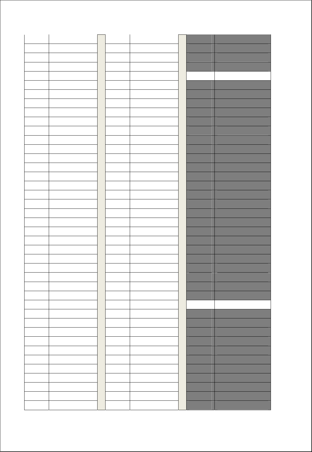
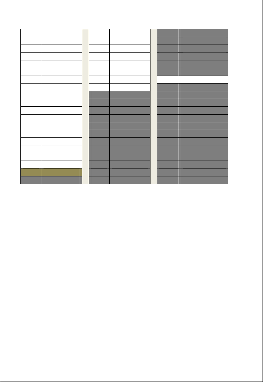
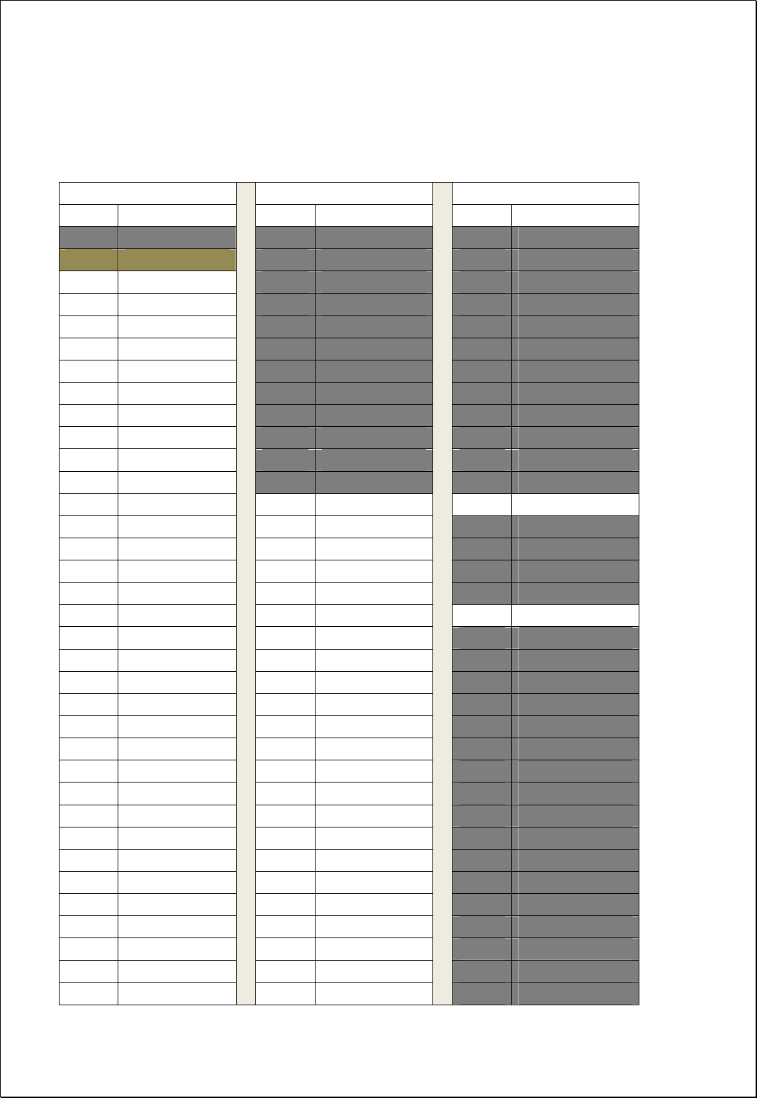
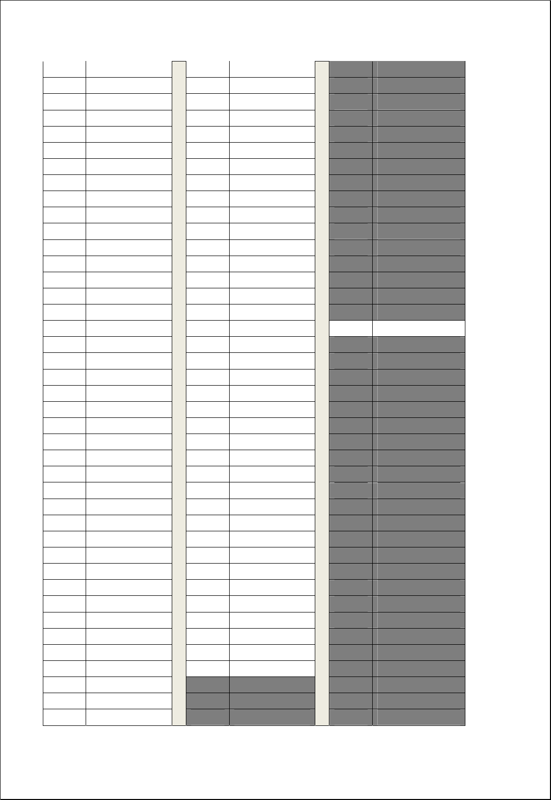
Appendix C 850MHz GSM & WCDMA Frequency Map
Gray Channels are not used
GSM WCDMA WCDMA
Channel Center freq.(MHz) Channel Center freq.(MHz) Channel Center freq.(MHz)
127 869.0 4345 869.0 995 869.1
128 869.2 4346 869.2 996 869.3
129 869.4 4347 869.4 997 869.5
130 869.6 4348 869.6 998 869.7
131 869.8 4349 869.8 999 869.9
132 870.0 4350 870.0 1000 870.1
133 870.2 4351 870.2 1001 870.3
134 870.4 4352 870.4 1002 870.5
135 870.6 4353 870.6 1003 870.7
136 870.8 4354 870.8 1004 870.9
137 871.0 4355 871.0 1005 871.1
138 871.2 4356 871.2 1006 871.3
139 871.4 4357 871.4 1007 871.5
140 871.6 4358 871.6 1008 871.7
141 871.8 4359 871.8 1009 871.9
142 872.0 4360 872.0 1010 872.1
143 872.2 4361 872.2 1011 872.3
144 872.4 4362 872.4 1012 872.5
145 872.6 4363 872.6 1013 872.7
146 872.8 4364 872.8 1014 872.9
147 873.0 4365 873.0 1015 873.1
148 873.2 4366 873.2 1016 873.3
149 873.4 4367 873.4 1017 873.5
150 873.6 4368 873.6 1018 873.7
151 873.8 4369 873.8 1019 873.9
152 874.0 4370 874.0 1020 874.1
153 874.2 4371 874.2 1021 874.3
154 874.4 4372 874.4 1022 874.5
155 874.6 4373 874.6 1023 874.7
156 874.8 4374 874.8 1024 874.9
157 875.0 4375 875.0 1025 875.1
158 875.2 4376 875.2 1026 875.3
159 875.4 4377 875.4 1027 875.5
160 875.6 4378 875.6 1028 875.7
161 875.8
4379 875.8 1029 875.9
52 / 54
162 876.0 4380 876.0 1030 876.1
163 876.2 4381 876.2 1031 876.3
164 876.4 4382 876.4 1032 876.5
165 876.6 4383 876.6 1033 876.7
166 876.8 4384 876.8 1034 876.9
167 877.0 4385 877.0 1035 877.1
168 877.2 4386 877.2 1036 877.3
169 877.4 4387 877.4 1037 877.5
170 877.6 4388 877.6 1038 877.7
171 877.8 4389 877.8 1039 877.9
172 878.0 4390 878.0 1040 878.1
173 878.2 4391 878.2 1041 878.3
174 878.4 4392 878.4 1042 878.5
175 878.6 4393 878.6 1043 878.7
176 878.8 4394 878.8 1044 878.9
177 879.0 4395 879.0 1045 879.1
178 879.2 4396 879.2 1046 879.3
179 879.4 4397 879.4 1047 879.5
180 879.6 4398 879.6 1048 879.7
181 879.8 4399 879.8 1049 879.9
182 880.0 4400 880.0 1050 880.1
183 880.2 4401 880.2 1051 880.3
184 880.4 4402 880.4 1052 880.5
185 880.6 4403 880.6 1053 880.7
186 880.8 4404 880.8 1054 880.9
187 881.0 4405 881.0 1055 881.1
188 881.2 4406 881.2 1056 881.3
189 881.4 4407 881.4 1057 881.5
190 881.6 4408 881.6 1058 881.7
191 881.8 4409 881.8 1059 881.9
192 882.0 4410 882.0 1060 882.1
193 882.2 4411 882.2 1061 882.3
194 882.4 4412 882.4 1062 882.5
195 882.6 4413 882.6 1063 882.7
196 882.8 4414 882.8 1064 882.9
197 883.0 4415 883.0 1065 883.1
198 883.2 4416 883.2 1066 883.3
199 883.4 4417 883.4 1067 883.5
200 883.6 4418 883.6 1068 883.7
201 883.8 4419 883.8 1069 883.9
202 884.0 4420 884.0 1070 884.1
53 / 54
203 884.2 4421 884.2 1071 884.3
204 884.4 4422 884.4 1072 884.5
205 884.6 4423 884.6 1073 884.7
206 884.8 4424 884.8 1074 884.9
207 885.0 4425 885.0 1075 885.1
208 885.2 4426 885.2 1076 885.3
209 885.4 4427 885.4 1077 885.5
210 885.6 4428 885.6 1078 885.7
211 885.8 4429 885.8 1079 885.9
212 886.0 4430 886.0 1080 886.1
213 886.2 4431 886.2 1081 886.3
214 886.4 4432 886.4 1082 886.5
215 886.6 4433 886.6 1083 886.7
216 886.8 4434 886.8 1084 886.9
217 887.0 4435 887.0 1085 887.1
218 887.2 4436 887.2 1086 887.3
219 887.4 4437 887.4 1087 887.5
220 887.6 4438 887.6 1088 887.7
221 887.8 4439 887.8 1089 887.9
222 888.0 4440 888.0 1090 888.1
223 888.2 4441 888.2 1091 888.3
224 888.4 4442 888.4 1092 888.5
225 888.6 4443 888.6 1093 888.7
226 888.8 4444 888.8 1094 888.9
227 889.0 4445 889.0 1095 889.1
228 889.2 4446 889.2 1096 889.3
229 889.4 4447 889.4 1097 889.5
230 889.6 4448 889.6 1098 889.7
231 889.8 4449 889.8 1099 889.9
232 890.0 4450 890.0 1100 890.1
233 890.2 4451 890.2 1101 890.3
234 890.4 4452 890.4 1102 890.5
235 890.6 4453 890.6 1103 890.7
236 890.8 4454 890.8 1104 890.9
237 891.0 4455 891.0 1105 891.1
238 891.2 4456 891.2 1106 891.3
239 891.4 4457 891.4 1107 891.5
240 891.6 4458 891.6 1108 891.7
241 891.8 4459 891.8 1109 891.9
242 892.0 4460 892.0 1110 892.1
243 892.2 4461 892.2 1111 892.3

54 / 54
244 892.4 4462 892.4 1112 892.5
245 892.6 4463 892.6 1113 892.7
246 892.8 4464 892.8 1114 892.9
247 893.0 4465 893.0 1115 893.1
248 893.2 4466 893.2 1116 893.3
249 893.4 4467 893.4 1117 893.5
250 893.6 4468 893.6 1118 893.7
251 893.8 4469 893.8 1119 893.9
252 894.0 4470 894.0 1120 894.1