126267 2 Weg Electric Motor Owners Manual User
103344 2 Weg Electric Motor Owners Manual 103344_2_WEG Electric Motor Owners Manual
125218 2 Weg Install Manual 2 125218_2_WEG Install Manual 2 125218_2_WEG Install Manual 2 pdf pumpproducts
107525 2 Weg Electric Motor Owners Manual 107525_2_WEG Electric Motor Owners Manual 107525_2_WEG Electric Motor Owners Manual pdf pumpproducts
103247 2 Weg Electric Motor Owners Manual 103247_2_WEG Electric Motor Owners Manual 103247_2_WEG Electric Motor Owners Manual pdf pumpproducts
103280 2 Weg Electric Motor Owners Manual 103280_2_WEG Electric Motor Owners Manual 103280_2_WEG Electric Motor Owners Manual pdf pumpproducts
User Manual: Pump 126267 2 Weg Electric Motor Owners Manual
Open the PDF directly: View PDF ![]() .
.
Page Count: 222 [warning: Documents this large are best viewed by clicking the View PDF Link!]
- 1. DEFINIÇÕES
- 2. RECOMENDAÇÕES INICIAIS
- 3. SEGURANÇA
- 4. MANUSEIO E TRANSPORTE
- 5. ARMAZENAMENTO
- 6. INSTALAÇÃO
- 6.1. Fundações para o motor
- 6.2. FIXAÇÃO DO MOTOR
- 6.3. BALANCEAMENTO
- 6.4. ACOPLAMENTOS
- 6.5. NIVELAMENTO
- 6.6. ALINHAMENTO
- 6.7. CONEXÃO DE MOTORES LUBRIFICADOS A ÓLEO OU DO TIPO OIL MIST
- 6.8. CONEXÃO DO SISTEMA DE REFRIGERAÇÃO À ÁGUA
- 6.9. CONEXÃO ELÉTRICA
- 6.10. CONEXÃO DOS DISPOSITIVOS DE PROTEÇÃO TÉRMICA
- 6.11. TERMORRESISTORES (Pt-100)
- 6.12. Conexão da Resistência de Aquecimento
- 6.13. MÉTODOS DE PARTIDA
- 6.14. MOTORES ALIMENTADOS POR INVERSOR DE Frequência
- 7. OPERAÇÃO
- 8. MANUTENÇÃO
- 8.1. INSPEÇÃO GERAL
- 8.2. LUBRIFICAÇÃO
- 8.2.1. Mancais de rolamento lubrificados a graxa
- 8.2.1.1. Motores sem graxeira
- 8.2.1.2. Motores com graxeira
- 8.2.1.3. Compatibilidade da graxa Mobil Polyrex EM com outras graxas
- 8.2.2. Mancais de rolamento lubrificados a óleo
- 8.2.3. Mancais de rolamento com lubrificação do tipo Oil Mist
- 8.2.4. Mancais de deslizamento
- 8.3. DESMONTAGEM E MONTAGEM
- 8.4. Procedimento para adequação da Resistência de Isolamento
- 8.5. Partes e peças
- 9. INFORMAÇÕES AMBIENTAIS
- 10. PROBLEMAS x SOLUÇÕES
- 11. TERMO DE GARANTIA
- 12. Declaração de Conformidade CE
- 1. Terminology
- 2. Initial Recommendations
- 3. Safety Instructions
- 4. Handling and Transport
- 4.1. Lifting
- 4.1.1. Horizontal motors with one eyebolt
- 4.1.2. Horizontal motor with two eyebolts
- 4.1.3. Vertical Motors
- 4.1.3.1. Procedures to place W22 motors in the vertical position
- 4.1.3.2. Procedures to place HGF motors in the vertical position
- 4.2 Procedures to place W22 vertical mount motors in horizontal position
- 4.1. Lifting
- 5. Storage
- 6. Installation
- 6.1. Foundations
- 6.2. MOTOR MOUNTING
- 6.3. Balancing
- 6.4. Couplings
- 6.5. Leveling
- 6.6. Alignment
- 6.7. Connection of oil lubricated or oil mist lubricated motors
- 6.8. Connection of the cooling water system
- 6.9. Electrical connection
- 6.10. Connection of the thermal protection devices
- 6.11. Resistance Temperature Detectors (Pt-100)
- 6.12. Connection of the space heaters
- 6.13. Starting Methods
- 6.14. Motors driven by Frequency Inverter
- 7. Commissioning
- 8. Maintenance
- 9. Environmental Information
- 10. Troubleshooting chart x solutions
- 11. Warranty Term
- 12. Ec declaration of conformity
- 1. Definiciones
- 2. Recomendaciones Iniciales
- 3. Seguridad
- 4. ManipulaciOn y Transporte
- 5. Almacenado
- 6. InstalaciOn
- 6.1. Cimientos para el motor
- 6.2. FijaciOn del motor
- 6.3. Balanceo
- 6.4. Acoplamientos
- 6.5. NivelaciOn
- 6.6. Alineamiento
- 6.7. ConexiOn de motores lubricados a aceite o de tipo Oil Mist
- 6.8. ConexiOn del sistema de refrigeraciOn a agua
- 6.9. ConexiOn ElEctrica
- 6.10. ConexiOn de los Dispositivos de Proteccion TErmica
- 6.11. Termoresistores (Pt-100)
- 6.12. Conexion de las resistencias de caldeo
- 6.13. MEtodos de Partida
- 6.14. Motores Alimentados por convertidor de Frecuencia
- 7. OperaciOn
- 8. Mantenimiento
- 8.1. InspecciOn General
- 8.2. LubricacIon
- 8.2.1. Cojinetes de rodamiento lubricados a grasa
- 8.2.1.1. Motores sin grasera
- 8.2.1.2. Motores con grasera
- 8.2.1.3. Compatibilidad de la grasa Mobil Polyrex EM con otras grasas
- 8.2.2. Cojinetes de rodamiento lubricados a aceite
- 8.2.3. Cojinetes de rodamiento con lubricación de tipo Oil Mist
- 8.2.4. Cojinetes de deslizamiento
- 8.3. Desmontaje y montaje
- 8.4. Procedimiento para adecuaciOn de la Resistencia de Aislamiento
- 8.5. Partes y Piezas
- 9. Informaciones Ambientales
- 10. Problemas y Soluciones
- 11. TErmino de GarantIa
- 12. DECLARACIoN DE CONFORMIDAD CE
- 1. Begriffserklärung
- 2. Allgemein
- 3. Sicherheitshinweise
- 4. Handhabung und Transport
- 4.1. Handhabung
- 4.1.1. Handhabung von horizontal aufgestellten Motoren mit einer Transportöse
- 4.1.2. Handhabung von horizontal aufgestellten Motoren mit zwei Transportösen
- 4.1.3. Handhabung von vertikal aufgestellten Motoren
- 4.1.3.1. Handhabung von vertikal aufgestellten Motoren der Baureihe W22
- 4.1.3.2. Handhabung von vertikal aufgestellten Motoren der Baureihe HGF
- 4.2. Vertikal aufgestellte Motoren der Reihe W22 in Horizontallage wenden
- 4.1. Handhabung
- 5. Lagerung
- 6. Installation
- 6.1. Fundamente für den Motor
- 6.2. Motoraufstellung
- 6.3. Auswuchten
- 6.4. Übertragungselemente
- 6.5. Nivellieren
- 6.6. Ausrichten
- 6.7. Anschluss von ölgeschmierten oder mit Schmierölnebel geschmierten Lagern
- 6.8. Anschlusssystem von Motoren mit Wasserkühlern
- 6.9. Elektrischer Anschluss
- 6.10. Schaltung von thermischen Schutzvorrichtungen
- 6.11. Widerstandsthermometer (Pt-100)
- 6.12. Anschluss der Stillstandsheizung
- 6.13. Anlaufmethoden
- 6.14. Motoren über Frequenzumrichter betrieben
- 7. Inbetriebnahme
- 8. Wartung
- 9. Information über den Umweltschutz
- 10. Störungssuche und Behebung
- 11. Gewährleistung
- 12. CE-Konformitätserklärung
--
Manual Geral de Instalação, Operação e
Manutenção de Motores Elétricos
Motors | Automation | Energy | Transmission & Distribution | Coatings
Installation, Operation and Maintenance
Manual of Electric Motors
Manual General de Instalación, Operación
y Mantenimiento de Motores Eléctricos
Installations-, Betriebs- und
Wartungsanleitung für Elektrische Motoren
www.weg.net
Motores Elétricos 3
MANUAL GERAL DE INSTALAÇÃO, OPERAÇÃO E
MANUTENÇÃO DE MOTORES ELÉTRICOS
Este manual apresenta informações referentes aos motores elétricos WEG de indução com
rotor de gaiola, com rotor de ímãs permanentes ou híbridos, de baixa e alta tensão, nas
carcaças IEC 56 a 630 e NEMA 42 a 9606/10.
As linhas listadas abaixo possuem informações adicionais, encontradas em manuais
específicos:
g Motores para extração de fumaça (Smoke Extraction Motor);
g Motores com freio eletromagnético;
g Motores para áreas classificadas.
Estes produtos estão de acordo com as seguintes normas, quando aplicáveis:
g NBR 17094-1: Máquinas Elétricas Girantes - Motores de Indução Parte 1: trifásicos.
g NBR 17094-2: Máquinas Elétricas Girantes - Motores de Indução - Parte 2: monofásicos.
g IEC 60034-1: Rotating Electrical Machines - Part 1: Rating and Performance.
g NEMA MG 1: Motors and Generators.
g CSA C 22.2 N°100: Motors and Generators.
g UL 1004-1: Rotating Electrical Machines - General Requirements.
Em caso de dúvidas sobre a aplicabilidade desse material, contate a WEG.

www.weg.net
Motores Elétricos4
PORTUGUÊS
ÍNDICE
1. DEFINIÇÕES 6
2. RECOMENDAÇÕES INICIAIS 7
2.1. SINAL DE ADVERTENCIA .................................................................................................................. 7
2.2. VERIFICAÇÃO NO RECEBIMENTO .................................................................................................. 7
2.3. PLACAS DE IDENTIFICAÇÃO ........................................................................................................... 8
3. SEGURANÇA 11
4. MANUSEIO E TRANSPORTE 12
4.1. IÇAMENTO ........................................................................................................................................ 12
4.1.1. Motores horizontais com um olhal de içamento ................................................................. 13
4.1.2. Motores horizontais com dois ou mais olhais de içamento .............................................. 13
4.1.3. Motores verticais .................................................................................................................... 14
4.1.3.1. Procedimento para colocação de motores W22 na posição vertical ............................ 15
4.1.3.2. Procedimento para colocação de motores HGF na posição vertical ........................... 16
4.2. PROCEDIMENTO PARA TOMBAMENTO DE MOTORES W22 VERTICAIS ................................ 17
5. ARMAZENAMENTO 19
5.1. SUPERFÍCIES USINADAS EXPOSTAS ........................................................................................... 19
5.2. EMPILHAMENTO ............................................................................................................................. 19
5.3. MANCAIS .......................................................................................................................................... 20
5.3.1 Mancais de rolamento lubrificados a graxa ......................................................................... 20
5.3.2 Mancais de rolamento com lubrificação a óleo ..................................................................20
5.3.3 Mancais de rolamento com lubrificação do tipo Oil Mist .................................................. 21
5.3.4 Mancais de deslizamento ....................................................................................................... 21
5.4. RESISTÊNCIA DE ISOLAMENTO ................................................................................................... 21
5.4.1. Procedimento para medição da resistência de isolamento .............................................. 21
6. INSTALAÇÃO 24
6.1. FUNDAÇÕES PARA O MOTOR ........................................................................................................ 25
6.2. FIXAÇÃO DO MOTOR ...................................................................................................................... 27
6.2.1. Fixação pelos pés ................................................................................................................... 27
6.2.2. Fixação por flange .................................................................................................................28
6.2.3. Fixação por pad ...................................................................................................................... 28
6.3. BALANCEAMENTO ..........................................................................................................................29
6.4. ACOPLAMENTOS .............................................................................................................................29
6.4.1. Acoplamento direto ................................................................................................................ 29
6.4.2. Acoplamento por engrenagem ............................................................................................. 29
6.4.3. Acoplamento por polias e correias ......................................................................................29
6.4.4. Acoplamento de motores equipados com mancais de deslizamento ............................. 29
6.5. NIVELAMENTO .................................................................................................................................30
6.6. ALINHAMENTO ................................................................................................................................ 30
6.7. CONEXÃO DE MOTORES LUBRIFICADOS A ÓLEO OU DO TIPO OIL MIST ............................. 31
6.8. CONEXÃO DO SISTEMA DE REFRIGERAÇÃO À ÁGUA .............................................................. 31
6.9. CONEXÃO ELÉTRICA ...................................................................................................................... 31

www.weg.net
Motores Elétricos 5
PORTUGUÊS
6.10. CONEXÃO DOS DISPOSITIVOS DE PROTEÇÃO TÉRMICA ....................................................... 34
6.11. TERMORRESISTORES (PT-100) .................................................................................................... 35
6.12. CONEXÃO DA RESISTÊNCIA DE AQUECIMENTO ..................................................................... 37
6.13. MÉTODOS DE PARTIDA ................................................................................................................ 37
6.14. MOTORES ALIMENTADOS POR INVERSOR DE FREQUÊNCIA ................................................ 38
6.14.1. Uso de filtros (dV/dt) .............................................................................................................39
6.14.1.1. Motor com fio circular esmaltado .................................................................................... 39
6.14.1.2. Motor com bobina pré-formada ....................................................................................... 39
6.14.2. Isolamento dos mancais ...................................................................................................... 39
6.14.3. Frequência de chaveamento ............................................................................................... 40
6.14.4. Limite da rotação mecânica ................................................................................................ 40
7. OPERAÇÃO 41
7.1. PARTIDA DO MOTOR ....................................................................................................................... 41
7.2. CONDIÇÕES DE OPERAÇÃO ..........................................................................................................43
7.2.1. Limites da severidade de vibração .......................................................................................44
8. MANUTENÇÃO 45
8.1. INSPEÇÃO GERAL ...........................................................................................................................45
8.2. LUBRIFICAÇÃO ................................................................................................................................ 45
8.2.1. Mancais de rolamento lubrificados a graxa ........................................................................46
8.2.1.1. Motores sem graxeira .........................................................................................................48
8.2.1.2. Motores com graxeira .........................................................................................................48
8.2.1.3. Compatibilidade da graxa Mobil Polyrex EM com outras graxas .................................48
8.2.2. Mancais de rolamento lubrificados a óleo .........................................................................49
8.2.3. Mancais de rolamento com lubrificação do tipo Oil Mist ................................................. 49
8.2.4. Mancais de deslizamento .....................................................................................................49
8.3. DESMONTAGEM E MONTAGEM ....................................................................................................50
8.3.1. Caixa de ligação ...................................................................................................................... 51
8.4. PROCEDIMENTO PARA ADEQUAÇÃO DA RESISTÊNCIA DE ISOLAMENTO ........................... 51
8.5. PARTES E PEÇAS ............................................................................................................................ 52
9. INFORMAÇÕES AMBIENTAIS 53
9.1. EMBALAGEM .................................................................................................................................... 53
9.2. PRODUTO ......................................................................................................................................... 53
10. PROBLEMAS x SOLUÇÕES 54
11. TERMO DE GARANTIA 55
12. DECLARAÇÃO DE CONFORMIDADE CE 56

www.weg.net
Motores Elétricos6
PORTUGUÊS
1. DEFINIÇÕES
Balanceamento: procedimento pelo qual a distribuição de massa de um corpo é verificada e, se necessário,
ajustada para garantir que o desbalanceamento residual ou as vibrações e forças nos mancais na frequência
de rotação mecânica estejam dentro de limites especificados nas normas internacionais.
Grau de balanceamento: indica a amplitude de pico da velocidade de vibração, expressa em mm/s, de um
rotor girando livre no espaço e é produto de um desbalanceamento específico e a velocidade angular do rotor
na velocidade máxima de operação.
Parte aterrada: partes metálicas eletricamente conectadas ao sistema de aterramento.
Parte viva: condutor ou parte condutora destinada para ser energizada em condições normais de uso,
incluindo o condutor neutro.
Pessoal autorizado: trabalhador que tem anuência formal da empresa.
Pessoal capacitado: trabalhador que atenda as seguintes condições, simultaneamente:
g Receba capacitação sob orientação e responsabilidade de profissional habilitado e autorizado;
g Trabalhe sob responsabilidade de profissional habilitado e autorizado.
Nota: a capacitação só é válida para a empresa que o capacitou e nas condições estabelecidas pelo profissional habilitado e
autorizado responsável pela capacitação.
Pessoal habilitado: trabalhador previamente qualificado e com registro no conselho de classe competente.
Pessoal qualificado: trabalhador que comprovar conclusão de curso específico na área elétrica pelo sistema oficial de
ensino.
www.weg.net
Motores Elétricos 7
PORTUGUÊS
2. RECOMENDAÇÕES INICIAIS
Motores elétricos possuem circuitos energizados, componentes girantes e superfícies quentes
durante sua operação normal que podem causar danos às pessoas. Dessa forma, todas as
atividades relacionadas ao seu transporte, armazenagem, instalação, operação e manutenção
devem ser realizadas por pessoal capacitado.
Devem ser observadas as normas e procedimentos vigentes no país de instalação.
A não observação das instruções indicadas neste manual e demais referenciadas no site pode resultar em
sérios danos pessoais e materiais e anular a garantia do produto.
Neste manual não são apresentadas todas as informações detalhadas sobre possíveis variantes construtivas e
nem considerados todos os casos de montagem, operação ou manutenção. Este documento contém
informações necessárias para que pessoas capacitadas possam executar o serviço. As imagens apresentadas
são meramente ilustrativas.
Para motores utilizados para extração de fumaça (Smoke Extraction Motors), consultar adicionalmente as
instruções do manual 50026367 (inglês) disponível no website www.weg.net.
Para operação de motores com freio, consultar as informações do manual do motofreio WEG 50000701
(português) / 50006742 (inglês) ou motofreio Intorq 50021505 (português) / 50021973 (inglês) disponíveis no
website www.weg.net.
Para informações sobre cargas radias e axiais admissíveis no eixo consultar o catálogo técnico do produto.
A correta definição das características do ambiente e da aplicação é de responsabilidade do
usuário.
Durante o período de garantia do motor, os serviços de reparo, revisão e recuperação devem ser
realizados por Assistentes Técnicos autorizados WEG para continuidade do termo de garantia.
2.1. SINAL DE ADVERTENCIA
Advertência sobre segurança e garantia.
2.2. VERIFICAÇÃO NO RECEBIMENTO
Todos os motores são testados durante o processo de fabricação.
No recebimento do motor, verificar se ocorreram danos durante o transporte. Na ocorrência de qualquer dano,
registrar por escrito junto ao agente transportador, e comunicar imediatamente a companhia seguradora e a
WEG. A não comunicação pode resultar no cancelamento da garantia.
Deve-se realizar uma inspeção completa no produto:
g Verificar se os dados contidos na placa de identificação estão de acordo com o pedido de compra;
g Remover os dispositivos de travamento de eixo (caso existam) e girar manualmente o eixo para verificar se o
mesmo gira livremente;
g Assegurar que o motor não tenha sido exposto à poeira e umidade excessiva durante o transporte;
g Não remover graxa de proteção da ponta do eixo, nem os tampões que fecham os furos da caixa de
ligação, caso existam. Estes itens de proteção devem ser mantidos até que a instalação completa seja
concluída.
www.weg.net
Motores Elétricos8
PORTUGUÊS
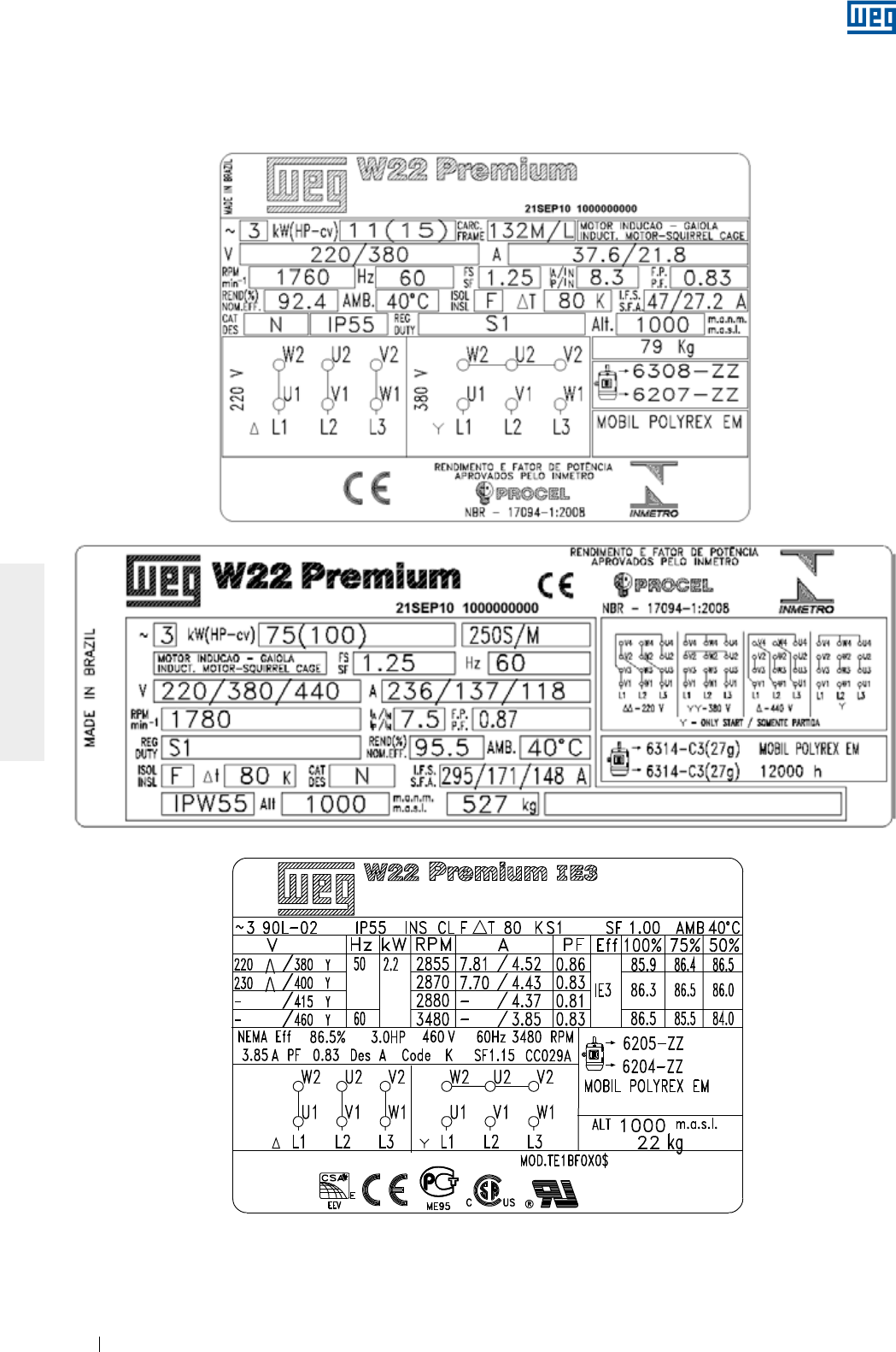
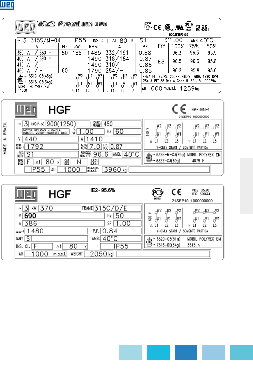
Figura 2.1 - Placa de identificação de motores IEC
2.3. PLACAS DE IDENTIFICAÇÃO
A placa de identificação contém as informações que descrevem as características construtivas e o desempenho do motor.
Nas Figura 2.1 e Figura 2.2 são apresentados exemplos de layouts das placas de identificação.
www.weg.net
Motores Elétricos 9
PORTUGUÊS
Figura 2.1 - Placa de identificação de motores IEC
www.weg.net
Motores Elétricos10
PORTUGUÊS
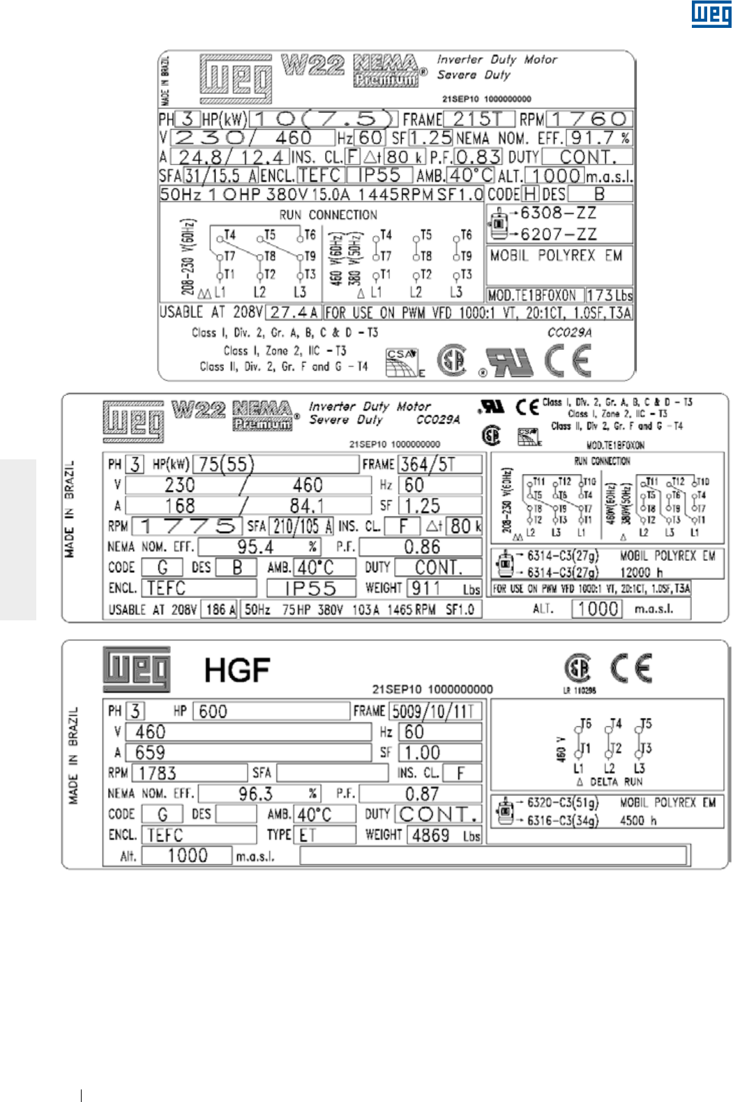
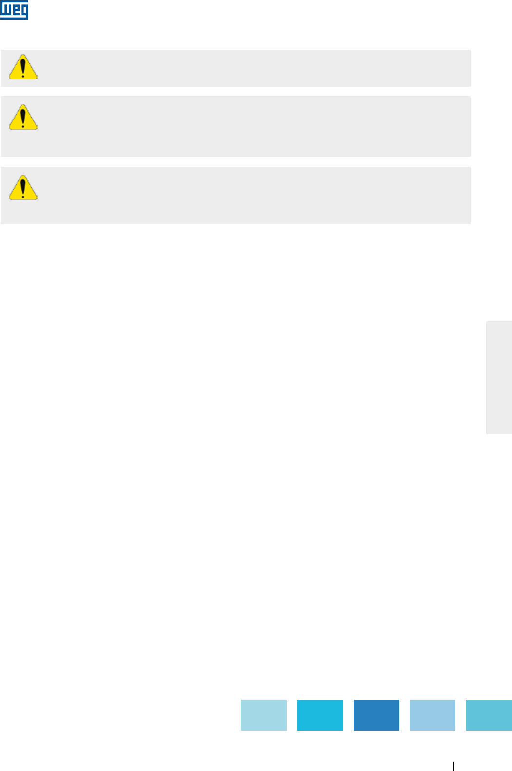
Figura 2.2 - Placa de identificação de motores NEMA
www.weg.net
Motores Elétricos 11
PORTUGUÊS
Motores elétricos possuem circuitos energizados, componentes girantes e superfícies quentes
durante sua operação normal que podem causar danos às pessoas. Dessa forma, todas as
atividades relacionadas ao seu transporte, armazenagem, instalação, operação e manutenção
devem ser realizadas apenas por pessoal capacitado.
3. SEGURANÇA
Durante a instalação e manutenção, os motores devem estar desconectados da rede, estar
completamente parados e cuidados adicionais devem ser tomados para evitar partidas acidentais.
Os profissionais que trabalham em instalações elétricas, seja na montagem, na operação ou na
manutenção, devem utilizar ferramentas apropriadas e serem instruídos sobre a aplicação das
normas e prescrições de segurança, inclusive sobre o uso de Equipamentos de Proteção Individual
(EPI), que devem ser cuidadosamente observados.
www.weg.net
Motores Elétricos12
PORTUGUÊS
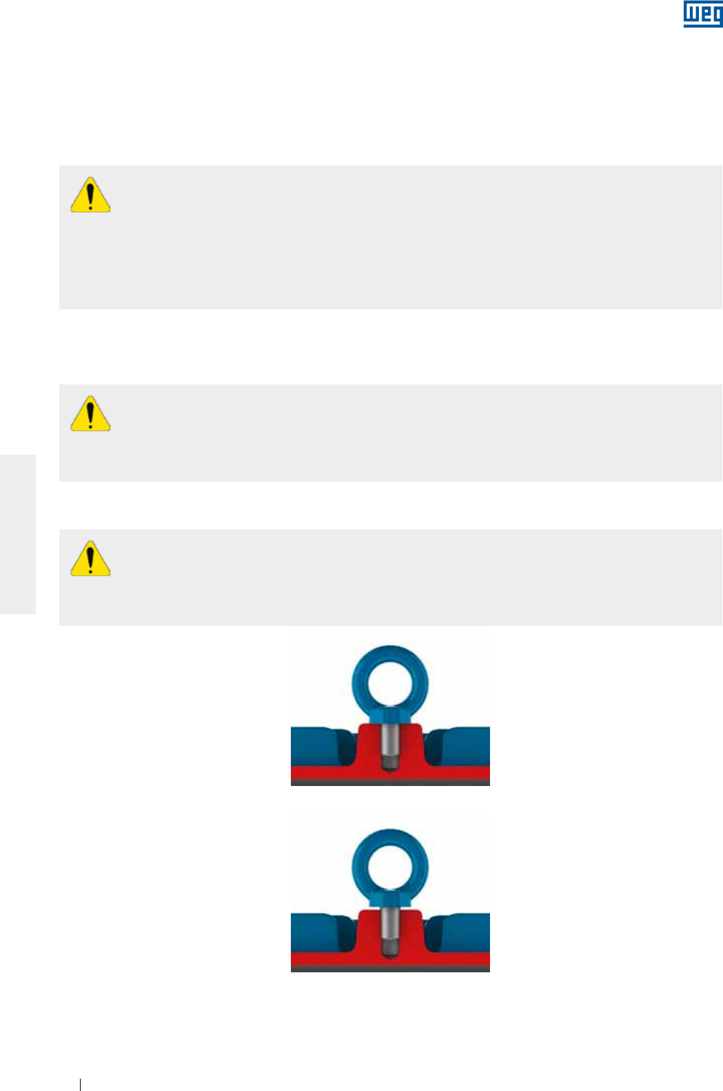
Figura 4.2 - Maneira incorreta de fixação do olhal de içamento
Figura 4.1 - Maneira correta de fixação do olhal de içamento
4. MANUSEIO E TRANSPORTE
Não utilizar os olhais de içamento para suspender o motor em conjunto com outros equipamentos,
como por exemplo: bases, polias, ventiladores, bombas, redutores, etc..
Olhais danificados, por exemplo, com trincas, deformações, etc., não devem ser utilizados. Verificar suas
condições antes de utilizá-los.
Os olhais de içamento em componentes como tampas, kit de ventilação forçada, entre outros, devem ser
utilizados somente para o içamento destes componentes de maneira isolada e nunca do motor completo.
Os dispositivos de travamento do eixo (utilizados para proteção durante o transporte), em motores
com rolamentos de rolos ou contato angular, devem ser utilizados para todo e qualquer transporte
do motor, mesmo que isso requeira o desacoplamento da máquina acionada.
Todos os motores HGF, independentemente do tipo de mancal, devem ter seu rotor travado para
transporte.
Antes de iniciar qualquer processo de içamento, certificar-se que os olhais estejam
adequadamente fixos, totalmente parafusados e com sua base em contato com a superfície a ser
içada, conforme Figura 4.1 (a Figura 4.2 exemplifica o uso incorreto).
Certificar-se que o equipamento utilizado no içamento e suas dimensões sejam adequados ao tamanho do
olhal e da massa do motor.
Motores embalados individualmente não devem ser içados pelo eixo ou embalagem, mas sim pelo(s) olhal(is)
de içamento (quando existentes) e com dispositivos adequados. Os olhais de içamento são dimensionados
para suportar apenas a massa do motor indicada na placa de identificação. Motores fornecidos em pallets
devem ser içados pela base do pallet.
Em nenhuma circunstância, a embalagem deve ser tombada.
Toda a movimentação deve ser realizada de forma suave, sem impactos, caso contrário os rolamentos podem
ser danificados bem como os olhais serem expostos a esforços excessivos, podendo provocar o rompimento
dos olhais.
4.1. IÇAMENTO
www.weg.net
Motores Elétricos 13
PORTUGUÊS
4.1.1. Motores horizontais com um olhal de içamento
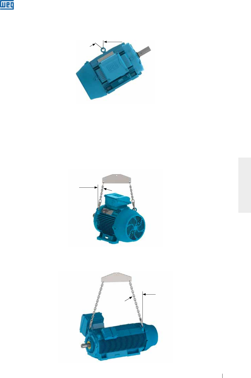
Para motores com um olhal de içamento, o ângulo máximo resultante durante o processo de içamento não
poderá exceder 30° em relação ao eixo vertical, conforme Figura 4.3.
Figura 4.3 - Ângulo máximo resultante para motores com um olhal de içamento
4.1.2. Motores horizontais com dois ou mais olhais de içamento
Para motores que possuem dois ou mais olhais para o içamento, todos os ollhais fornecidos devem ser
utilizados simultaneamente para o içamento.
Existem duas disposições de olhais possíveis (verticais e inclinados), conforme apresentadas a seguir:
g Motores com olhais verticais, conforme Figura 4.4, o ângulo máximo resultante deve ser de 45° em relação
ao eixo vertical. Recomenda-se a utilização de uma barra separadora (spreader bar), para manter o elemento
de içamento (corrente ou cabo) no eixo vertical e evitando danos à superfície do motor.
Figura 4.4 - Ângulo máximo resultante para motores com dois ou mais olhais de içamento
45° Máx.
Para motores HGF, conforme Figura 4.5, o ângulo máximo resultante deve ser de 30° em relação ao eixo
vertical;
Figura 4.5 - Ângulo máximo resultante para motores HGF horizontais
30° Máx.
30° Máx.
www.weg.net
Motores Elétricos14
PORTUGUÊS
g Motores com olhais inclinados, conforme Figura 4.6, é necessária a utilização de uma barra separadora
(spreader bar), para manter o elemento de içamento (corrente, cabo, etc.) no eixo vertical e assim também
evitar danos à superfície do motor.
Figura 4.6 - Uso de barra separadora no içamento
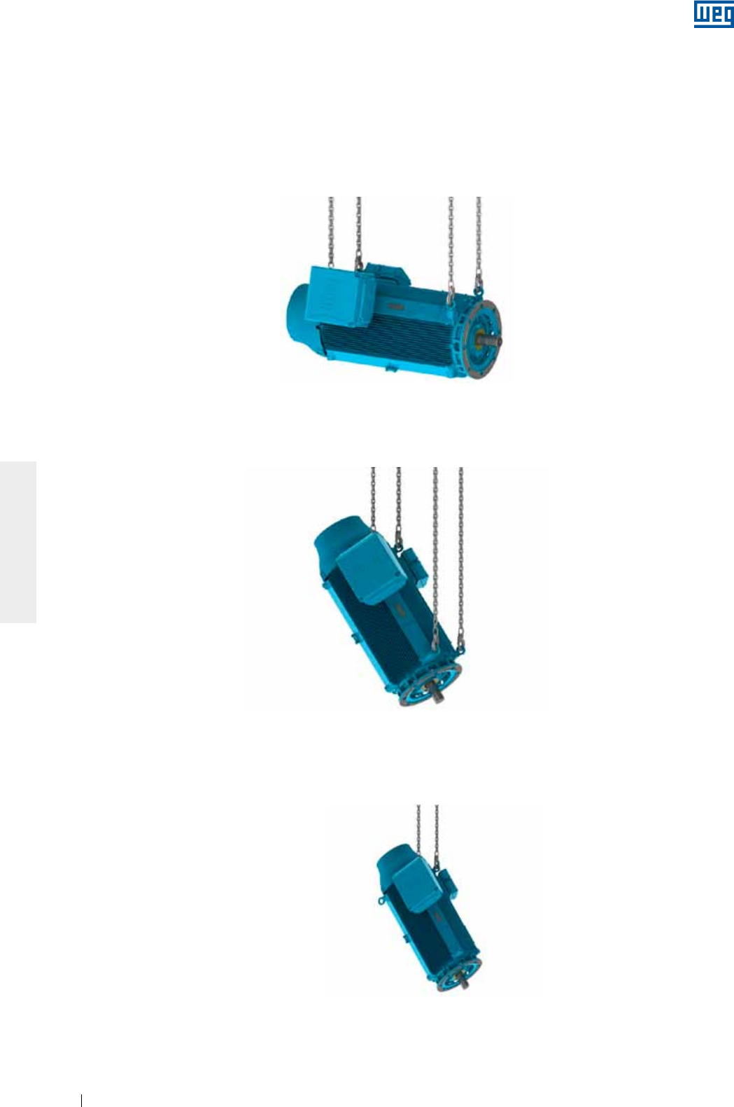
4.1.3. Motores verticais
Para motores verticais é necessária a utilização de uma barra separadora (spreader bar), para manter o
elemento de içamento (corrente, cabo) no eixo vertical e assim também evitar danos à superfície do motor
(conforme Figura 4.7).
Figura 4.7 - Içamento de motores verticais
Utilizar sempre os olhais que estão dispostos na parte superior do motor em relação à posição de
montagem e diametralmente opostos (ver Figura 4.8).
Figura 4.8 - Içamento de motores HGF
www.weg.net
Motores Elétricos 15
PORTUGUÊS
4.1.3.1. Procedimento para colocação de motores W22 na posição vertical
De forma geral, por questões de segurança durante o transporte, os motores verticais são embalados e
fornecidos na posição horizontal.
Para a colocação de motores W22 com olhais inclinados (ver Figura 4.6) na vertical, devem ser seguidos os
passos a seguir:
1. Certificar-se que os olhais estão adequadamentefixos (conforme Figura 4.1);
2. Remover o motor da embalagem utilizando os olhais superiores (conforme Figura 4.9);
Figura 4.9 - Remoção do motor da embalagem
3. Instalar o segundo par de olhais (conforme Figura 4.10);
Figura 4.10 - Instalação do segundo par de olhais
4. Reduzir a carga sobre o primeiro par de olhais para iniciar a rotação do motor (conforme Figura 4.11). Esse
procedimento deve ser realizado de forma lenta e cautelosa.
Figura 4.11 - Resultado final: motor posicionado na vertical
www.weg.net
Motores Elétricos16
PORTUGUÊS
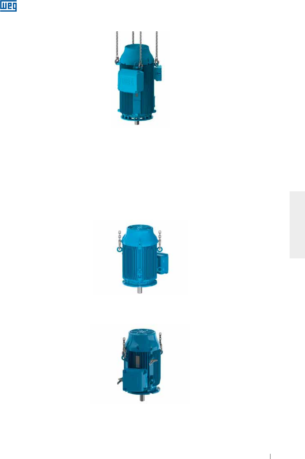
4.1.3.2. Procedimento para colocação de motores HGF na posição vertical
Os motores verticais HGF são fornecidos com oito pontos de içamento, sendo quatro na parte dianteira e
quatro na parte traseira. Geralmente são transportados na posição horizontal, mas para a instalação precisam
ser colocados na posição vertical.
Para a colocação de motores HGF na posição vertical, devem ser seguidos os passos a seguir:
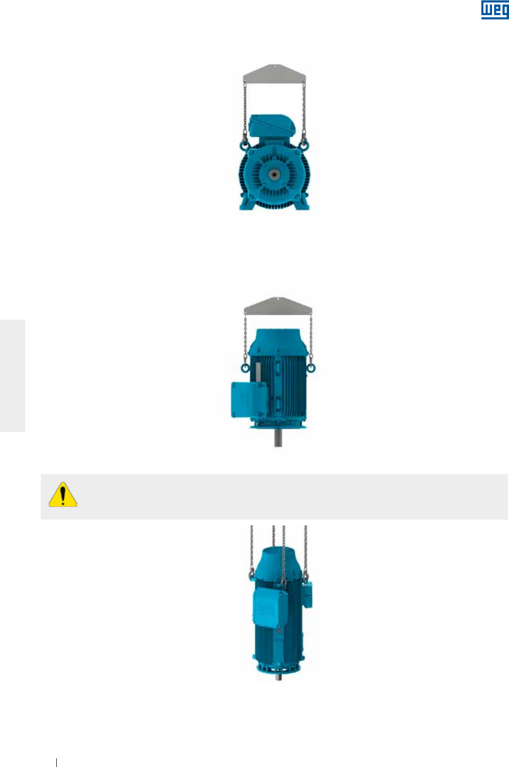
1. Levantar o motor através dos quatro olhais laterais, utilizando duas talhas (conforme figura 4.12);
Figura 4.12 - Içamento do motor HGF utilizando duas talhas
2. Baixar a talha que está presa à parte dianteira do motor e ao mesmo tempo levantar a talha que está presa
no lado traseiro do motor até que o motor atinja o equilíbrio (conforme Figura 4.13);
Figura 4.13 - Colocação de motor HGF na vertical
3. Soltar a talha presa na parte dianteira do motor e girar o motor 180° para possibilitar a fixação da talha
solta nos outros dois olhais da parte traseira do motor (conforme Figura 4.14);
Figura 4.14 - Suspensão de motor HGF pelos olhais traseiros
www.weg.net
Motores Elétricos 17
PORTUGUÊS
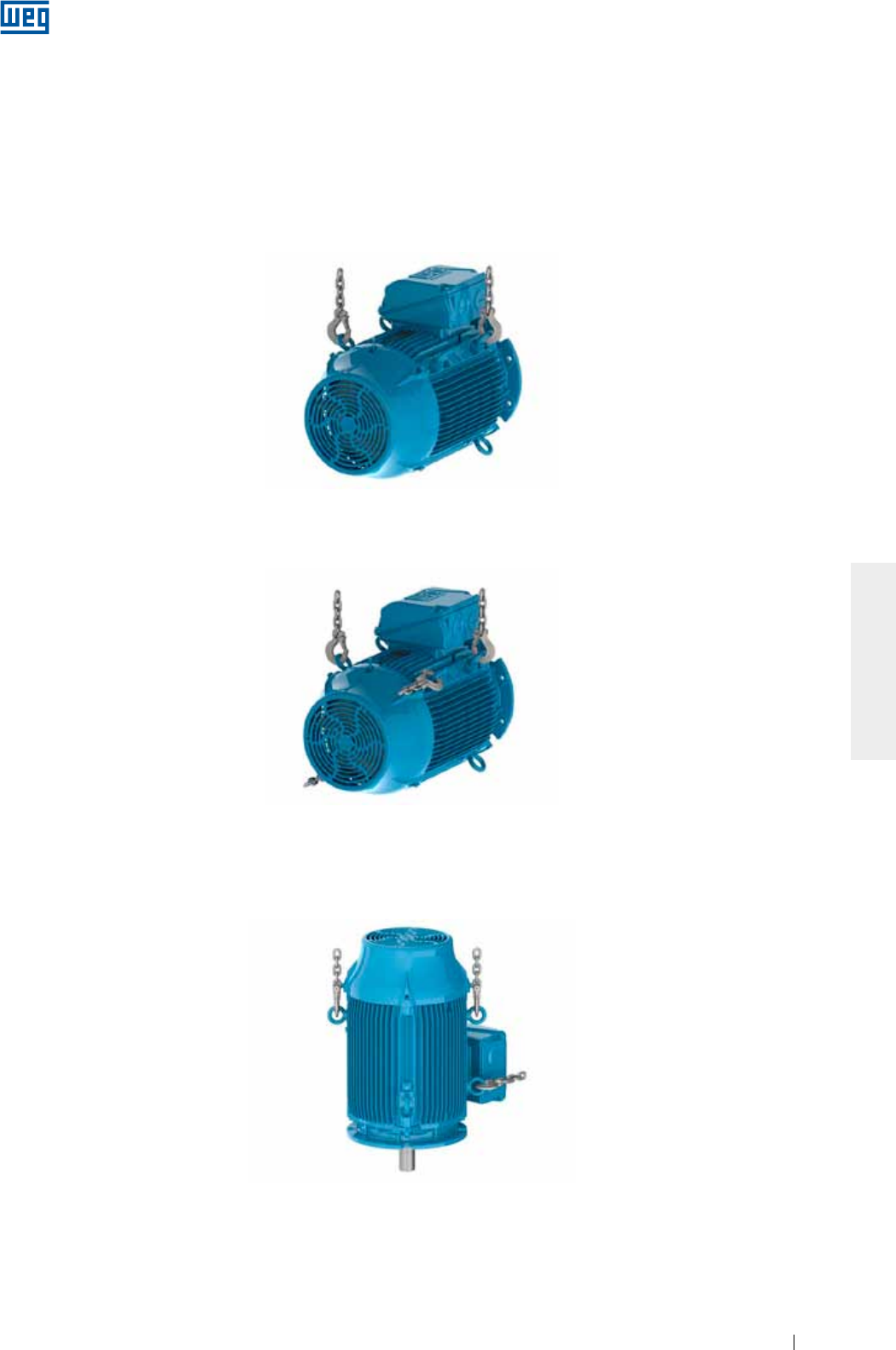
4. Fixar a talha solta nos outros dois olhais da parte traseira do motor e levantá-la até que o motor fique na
posição vertical (conforme Figura 4.15).
Figura 4.15 - Motor HGF na posição vertical
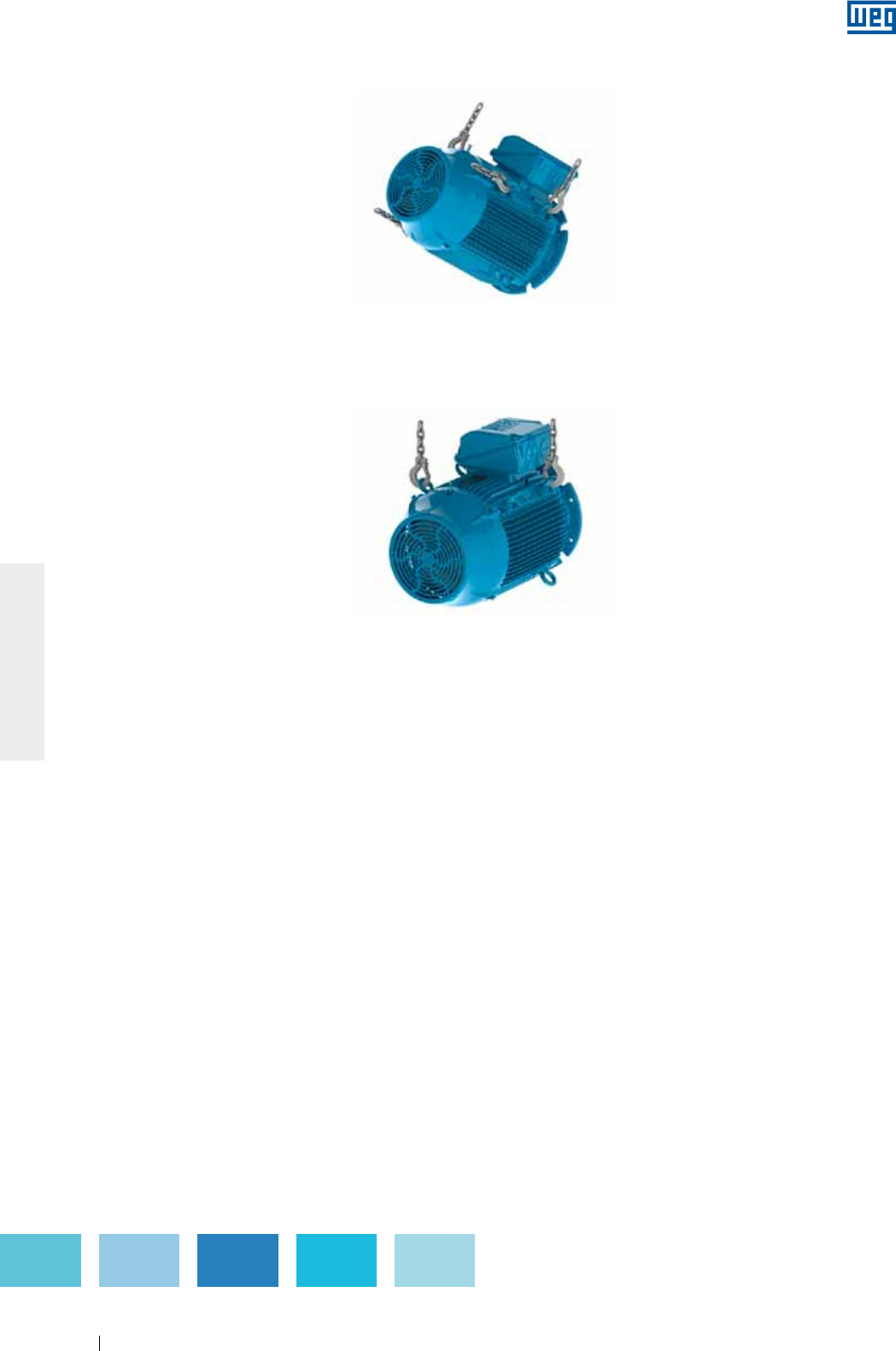
Estes procedimentos servem para movimentação de motores construídos para a montagem na posição
vertical. Estes mesmos procedimentos podem ser utilizados para a colocação do motor da posição horizontal
para a posição vertical e vice-versa.
4.2. PROCEDIMENTO PARA TOMBAMENTO DE MOTORES W22 VERTICAIS
Para realizar o tombamento de motores W22 originalmente na vertical, siga os passos mostrados a seguir:
1. Certificar-se que os olhais estão adequadamente fixos (conforme item 4.1);
2. Instalar o primeiro par de olhais e suspender o motor (conforme Figura 4.16);
Figura 4.16 - Instalação do primeiro par de olhais
3. Instalar o segundo par de olhais (conforme Figura 4.17);
Figura 4.17 - Instalação do segundo par de olhais
www.weg.net
Motores Elétricos18
PORTUGUÊS
5. Remover o primeiro par de olhais, olhais (conforme Figura 4.19).
Figura 4.19 - Resultado final: motor posicionado na posição horizontal
Figura 4.18 - Motor está sendo girado para a posição horizontal
4. Reduzir a carga sobre o primeiro par de olhais para iniciar a rotação do motor (conforme Figura 4.18). Esse
procedimento deve ser realizado de forma lenta e cautelosa.
www.weg.net
Motores Elétricos 19
PORTUGUÊS
5. ARMAZENAMENTO
Se os motores não forem instalados imediatamente, recomenda-se armazená-los em local seco com umidade
relativa do ar de até 60%, com temperatura ambiente acima de 5 °C e abaixo de 40 °C, isento de poeira,
vibrações, gases, agentes corrosivos, com temperatura uniforme, em posição normal e sem apoiar sobre eles
outros objetos. Remova polias (caso existam) da ponta de eixo, e as mantenha livre e com graxa protetiva para
evitar corrosão.
Caso o motor possua resistência de aquecimento, esta deverá ser energizada sempre que o motor não estiver
em operação. Isto se aplica também para os casos em que o motor estiver instalado, porém fora de uso por
um longo período. Nestas situações, dependendo das condições do ambiente, poderá ocorrer condensação
de água no interior do motor, provocando queda na resistência de isolamento. Os motores devem ser
armazenados de tal modo que a drenagem seja facilitada (informações adicionais estão disponíveis no item 6).
As resistências de aquecimento nunca devem estar energizadas enquanto o motor estiver
operando.
5.1. SUPERFÍCIES USINADAS EXPOSTAS
Todas as superfícies usinadas expostas (por exemplo, ponta de eixo e flange) são protegidas na fábrica por um
inibidor de oxidação temporário. Esta película protetora deve ser reaplicada periodicamente durante o período
de armazenagem (pelo menos a cada seis meses) ou quando for removida ou estiver deteriorada.
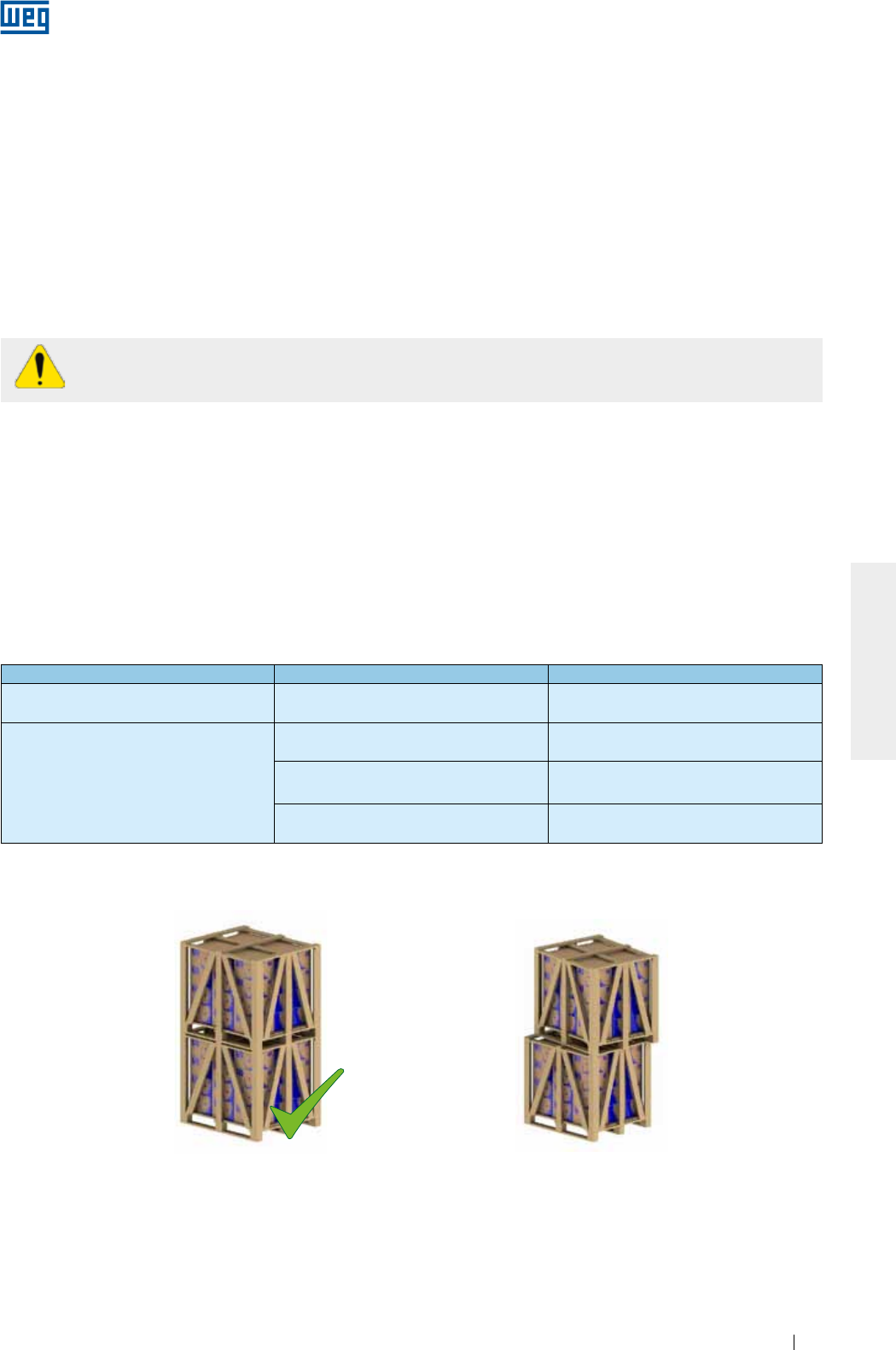
5.2. EMPILHAMENTO
O empilhamento de embalagens durante o armazenamento não deve ultrapassar 5 metros de altura,
obedecendo-se aos critérios da Tabela 5.1:
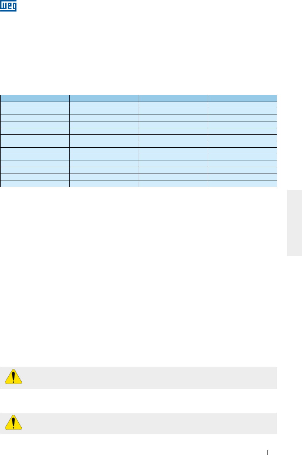
Tabela 5.1 - Empilhamento máximo recomendado
Tipo de embalagem Carcaças Quantidade máxima de empilhamento
Caixa de papelão IEC 63 a 132
NEMA 143 a 215
Indicada na aba superior da caixa de
papelão
Engradado de madeira
IEC 63 a 315
NEMA 48 a 504/5 06
IEC 355
NEMA 586/7 e 588/9 03
HGF IEC 315 a 630
HGF NEMA 5000 a 9600 Indicado na própria embalagem
Notas:
1) Não empilhar embalagens maiores sobre menores;
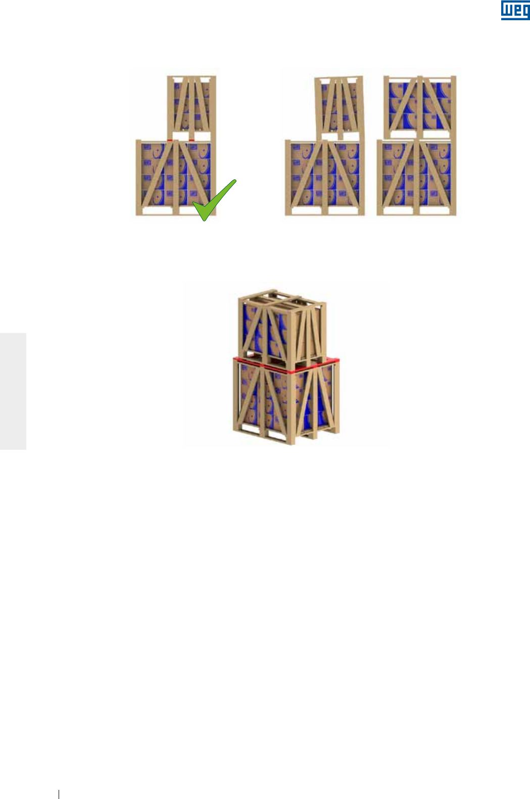
2) Posicionar corretamente uma embalagem sobre a outra (ver Figura 5.1 e Figura 5.2);
Figura 5.1 - Montagem adequada Figura 5.2 - Montagem inadequada
X
www.weg.net
Motores Elétricos20
PORTUGUÊS
Figura 5.5 - Utilização de sarrafos adicionais para empilhamento
5.3. MANCAIS
5.3.1 Mancais de rolamento lubrificados a graxa
Recomenda-se girar o eixo do motor pelo menos uma vez ao mês (manualmente, no mínimo cinco voltas,
deixando o eixo em posição diferente da original).
Obs.: caso o motor possua dispositivo de travamento do eixo, este deve ser retirado antes de girar o eixo e ser
recolocado novamente antes de transportar o motor.
Motores verticais podem ser armazenados na posição vertical ou na posição horizontal.
Para motores com rolamento aberto armazenados por mais de seis meses, os rolamentos devem ser
relubrificados, conforme item 8.2, antes da entrada em operação.
Caso o motor permaneça armazenado por um período superior a dois anos, recomenda-se substituir os
rolamentos ou então estes devem ser removidos, lavados, inspecionados e relubrificados (conforme item 8.2).
5.3.2 Mancais de rolamento com lubrificação a óleo
O motor deve ser armazenado na sua posição original de funcionamento e com óleo nos mancais. O nível do
óleo deve ser respeitado, permanecendo na metade do visor de nível.
Durante o período de armazenagem, deve-se retirar o dispositivo de travamento do eixo e, mensalmente,
rotacionar o eixo manualmente (cinco voltas), para recircular o óleo e conservar o mancal em boas condições.
Sendo necessário movimentar o motor, o dispositivo de travamento do eixo deve ser reinstalado.
Para motores armazenados por mais de seis meses, os rolamentos devem ser relubrificados (conforme item
8.2), antes da entrada em operação.
Caso o motor permaneça armazenado por um período maior que dois anos, recomenda-se substituir os
rolamentos ou então estes devem ser removidos, lavados, inspecionados e relubrificados (conforme item 8.2).
O óleo dos mancais dos motores verticais, que são transportados na posição horizontal, é retirado para evitar
vazamento durante o transporte. Após o recebimento, esses motores devem ser colocados na posição vertical
e seus mancais devem ser lubrificados.
Figura 5.3 - Empilhamento adequado Figura 5.4 - Empilhamento inadequado
X
4) Para o empilhamento de um volume menor sobre um volume maior, acrescentar sarrafos transversais entre os mesmos, quando o
maior não oferecer resistência ao peso do menor (ver Figura 5.5). Esta situação normalmente ocorre com os volumes dos motores de
carcaça acima da IEC 225S/M (NEMA 364/5T).
3) Os pés das embalagens superiores devem estar apoiados sobre calços de madeiras (Figura 5.3) e não sobre as fitas de aço e nem
tampouco ficar sem apoio (Figura 5.4);
www.weg.net
Motores Elétricos 21
PORTUGUÊS
5.3.3 Mancais de rolamento com lubrificação do tipo
Oil Mist
Tamanho de rolamento Quantidade de óleo (ml) Tamanho de rolamento Quantidade de óleo (ml)
6201 15 6309 65
6202 15 6311 90
6203 15 6312 105
6204 25 6314 150
6205 25 6315 200
6206 35 6316 250
6207 35 6317 300
6208 40 6319 350
6209 40 6320 400
6211 45 6322 550
6212 50 6324 600
6307 45 6326 650
6308 55 6328 700
Durante qualquer manuseio do motor, os mancais devem estar sem óleo. Dessa forma, antes da entrada em
operação, todo o óleo dos mancais deve ser drenado. Após a instalação, caso o sistema de névoa não esteja
em operação, o óleo deve ser recolocado para garantir a conservação do mancal. Neste caso, deve-se
também proceder com o giro semanal do eixo.
5.3.4 Mancais de deslizamento
O motor deve ser armazenado na sua posição original de funcionamento, e com óleo nos mancais. O nível do
óleo deve ser respeitado, permanecendo na metade do visor de nível.
Durante o período de armazenagem, deve-se retirar o dispositivo de travamento do eixo e, mensalmente,
rotacionar o eixo manualmente (cinco voltas) (e a 30 rpm, no mínimo) para recircular o óleo e conservar o
mancal em boas condições de operação. Caso seja necessário movimentar o motor, o dispositivo de
travamento do eixo deve ser reinstalado.
Para motores armazenados por mais de seis meses, os mancais devem ser relubrificados, (conforme item 8.2)
antes da entrada em operação.
Caso o motor fique armazenado por um período maior que o intervalo de troca de óleo, ou não seja possível
rotacionar o eixo do motor, o óleo deve ser drenado e aplicada uma proteção anticorrosiva e
desumidificadores.
Tabela 5.2 - Quantidade de óleo por rolamento
5.4. RESISTÊNCIA DE ISOLAMENTO
Recomenda-se medir periodicamente a resistência de isolamento dos motores, para assim avaliar as
condições de armazenamento sob o ponto de vista elétrico. Se forem observadas quedas nos valores de
resistência de isolamento, as condições do armazenamento devem ser analisadas, avaliadas e corrigidas,
quando necessário.
5.4.1. Procedimento para medição da resistência de isolamento
A medição da resistência de isolamento deve ser realizada em área segura.
Para evitar o risco de choque elétrico, descarregue os terminais imediatamente antes e depois de
cada medição. Caso o motor possua capacitores, estes devem ser descarregados.
A resistência de isolamento deve ser medida com um megômetro e com o motor parado, frio e completamente
desconectado da rede elétrica.
O motor deve ser armazenado na posição horizontal. Preencher os mancais com óleo mineral ISO VG 68 com
a quantidade de óleo indicada na Tabela 5.2 (também válida para rolamentos com dimensões equivalentes).
Após a colocação de óleo nos mancais, gire o eixo (mínimo de cinco voltas).
Durante o período de armazenagem, deve-se retirar o dispositivo de travamento do eixo (quando fornecido) e,
semanalmente, rotacionar o eixo manualmente (cinco voltas), deixando o eixo em posição diferente da original.
Sendo necessário movimentar o motor, o dispositivo de travamento do eixo deve ser reinstalado.
Caso o motor permaneça armazenado por um período maior que dois anos, recomenda-se substituir os
rolamentos ou então estes devem ser removidos, lavados, inspecionados e relubrificados (conforme item 8.2).
www.weg.net
Motores Elétricos22
PORTUGUÊS
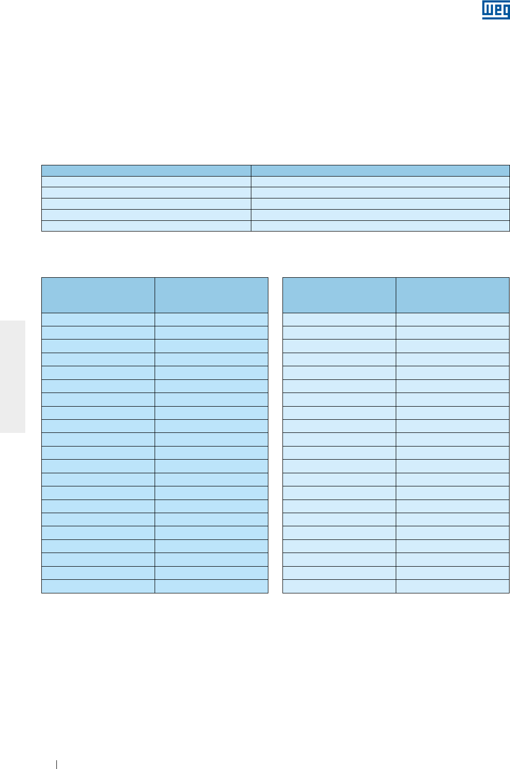
Tabela 5.3 - Tensão para medição da resistência de isolamento
Tensão nominal do motor (V) Tensão aplicada para a medição da resistência de isolamento (V)
< 1000 500
1000 - 2500 500 - 1000
2501 - 5000 1000 - 2500
5001 - 12000 2500 - 5000
> 12000 5000 - 10000
A medição da resistência de isolamento deve ser corrigida para a temperatura de 40 °C conforme Tabela 5.4
Tabela 5.4 - Fator de correção da resistência de isolamento para 40 °C
Temperatura de medição
da resistência de
isolamento (°C)
Fator de correção da
resistência de isolamento
para 40 °C
10 0,125
11 0,134
12 0,144
13 0,154
14 0,165
15 0,177
16 0,189
17 0,203
18 0,218
19 0,233
20 0,250
21 0,268
22 0,287
23 0,308
24 0,330
25 0,354
26 0,379
27 0,406
28 0,435
29 0,467
30 0,500
Temperatura de medição
da resistência de
isolamento (°C)
Fator de correção da
resistência de isolamento
para 40 °C
30 0,500
31 0,536
32 0,574
33 0,616
34 0,660
35 0,707
36 0,758
37 0,812
38 0,871
39 0,933
40 1,000
41 1,072
42 1,149
43 1,231
44 1,320
45 1,414
46 1,516
47 1,625
48 1,741
49 1,866
50 2,000
A condição do isolamento do motor deverá ser avaliada comparando-se o valor medido com os valores da
Tabela 5.5 (referenciados a 40 °C):
É recomendável que cada fase seja isolada e testada separadamente, permitindo que seja feita uma
comparação entre a resistência de isolamento em cada fase. Para testar uma das fases, as demais fases
devem estar aterradas.
O teste de todas as fases simultaneamente avalia apenas a resistência de isolamento contra o terra. Neste
caso não é avaliada a resistência de isolamento entre as fases.
Os cabos de alimentação, chaves, capacitores, e outros equipamentos externos ligados ao motor podem
influenciar consideravelmente a medição da resistência de isolamento. Ao realizar estas medições, todos os
equipamentos externos devem estar desconectados e aterrados.
A leitura da resistência de isolamento deve ser realizada após a tensão ser aplicada pelo período de um minuto
(1 min). A tensão a ser aplicada deve obedecer a Tabela 5.3.
www.weg.net
Motores Elétricos 23
PORTUGUÊS
Os dados indicados na tabela servem apenas como valores de referências. Sugere-se manter o histórico da
resistência de isolamento do motor durante toda a sua vida.
Se a resistência de isolamento estiver baixa, o estator do motor pode estar úmido. Nesse caso, recomenda-se
levá-lo até um Assistente Técnico Autorizado WEG para que sejam realizados a avaliação e o reparo adequado.
Este serviço não é coberto pelo Termo de Garantia.
Para procedimento de adequação da resistência de isolamento, ver item 8.4.
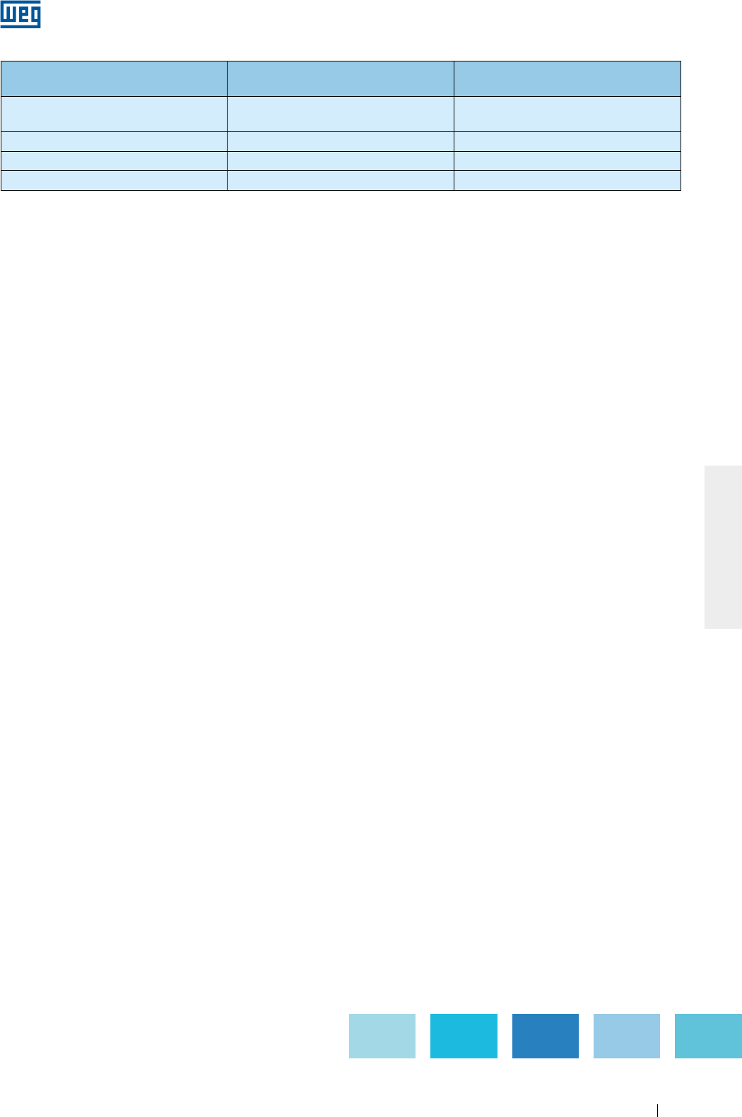
Tabela 5.5 - Avaliação do sistema de isolamento
Valor limite para tensão nominal
até 1,1 kV (M)
Valor limite para tensão nominal
acima de 1,1 kV (M) Situação
Até 5 Até 100 Perigoso, o motor não deve
operar nessa condição.
Entre 5 e 100 Entre 100 e 500 Regular
Entre 100 e 500 Acima de 500 Bom
Acima de 500 Acima de 1000 Excelente
www.weg.net
Motores Elétricos24
PORTUGUÊS
6. INSTALAÇÃO
A instalação de motores deve ser feita por profissionais capacitados com conhecimentos sobre as
normas e as prescrições de segurança.
Antes de continuar com o procedimento de instalação alguns pontos devem ser avaliados:
1. Resistência de isolamento: deve estar dentro dos valores aceitáveis (ver item 5.4).
2. Mancais:
a. Rolamentos: se apresentarem sinais de oxidação, devem ser substituídos. Caso não apresentem
oxidação, realize o procedimento de relubrificação conforme descrito no item 8.2. Motores armazenados
por um período superior a dois anos devem ter seus rolamentos substituídos antes de colocados em
operação.
b. Mancais de deslizamento: para motores armazenados por período igual ou maior que o intervalo de troca
de óleo, devem ter seu óleo substituído. Caso o óleo tenha sido retirado, é necessário retirar o
desumificador e recolocar o óleo no mancal. Maiores informação estão descritas no item 8.2.
3. Condição dos capacitores de partida: para motores monofásicos armazenados por um período maior que
dois anos, é recomendado que seus capacitores de partida sejam substituídos.
4. Caixa de ligação:
a. Devem estar limpas e secas no seu interior.
b. Os elementos de contato devem estar isentos de oxidação e corretamente conectados (ver itens 6.9 e
6.10).
c. As entradas de cabos não utilizadas devem estar corretamente seladas, a tampa da caixa de ligação
deve ser fechada e as vedações devem estar em condições apropriadas para atender o grau de proteção
do motor.
5. Ventilação: as aletas, a entrada e a saída de ar devem estar limpas e desobstruídas. A distância de
instalação recomendada entre as entradas de ar do motor e a parede não deve ser inferior a ¼ (um quarto)
do diâmetro da entrada de ar. Deve-se assegurar espaço suficiente para realização de serviços de limpeza
(ver item 7).
6. Acoplamento: remover o dispositivo de travamento do eixo (caso exista) e a graxa de proteção contra
corrosão da ponta do eixo e do flange somente pouco antes de instalar o motor (ver item 6.4).
7. Dreno: devem sempre estar posicionados de forma que a drenagem seja facilitada (no ponto mais baixo do
motor. Caso exista uma seta indicativa no corpo do dreno, o dreno deve ser montado para que a seta aponte
para baixo).
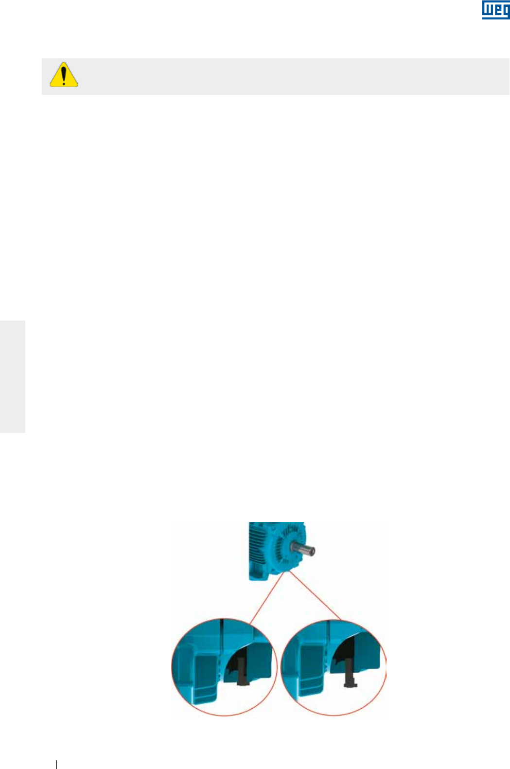
Motores com bujões de dreno de borracha saem de fábrica na posição fechada e devem ser abertos
periodicamente para permitir a saída da água condensada. Para ambientes com elevada condensação de
água e motores com grau de proteção IP55, os drenos podem ser montados na posição aberta (ver Figura 6.1).
Para motores com grau de proteção IP56, IP65 ou IP66, os drenos devem permanecer na posição fechada
(ver Figura 6.1), sendo abertos apenas durante a manutenção do motor.
Motores com lubrificação do tipo
Oil Mist
devem ter seus drenos conectados a um sistema de coleta
específico (ver Figura 6.12).
Figura 6.1 - Detalhe do dreno de borracha montado na posição fechado e aberto.
Dreno fechado Dreno aberto
www.weg.net
Motores Elétricos 25
PORTUGUÊS
Remova ou fixe completamente a chaveta antes de ligar o motor.
8. Recomendações adicionais:
a. Confira o sentido de rotação do motor, ligando-o a vazio antes de acoplá-lo à carga.
b. Para motores montados na vertical com a ponta de eixo para baixo, recomenda-se o uso de chapéu para
evitar a penetração de corpos estranhos no interior do motor.
c. Para motores montados na vertical com a ponta de eixo para cima, recomenda-se o uso de um defletor
de água (water slinger ring) para evitar a penetração de água pelo eixo.
6.1. FUNDAÇÕES PARA O MOTOR
Fundação é o elemento estrutural, base natural ou preparada, destinada a suportar os esforços produzidos
pelos equipamentos instalados, permitindo a operação destes com estabilidade, desempenho e segurança.
O projeto das fundações deve considerar as estruturas adjacentes para evitar influência de um equipamento
sobre o outro, a fim de que não ocorra a propagação de vibrações.
A fundação deve ser plana e a sua escolha, detalhamento e execução exige as características:
a) Da construção do próprio equipamento, envolvendo não somente os valores e forma de atuação das
cargas, como ainda sua finalidade e limites máximos das deformações e vibrações compatíveis em cada
caso (exemplo, motores com valores reduzidos de: nível de vibração, planicidade dos pés, concentricidade
do flange, batimento do flange, etc.);
b) Das construções vizinhas, compreendendo o estado de conservação, estimativa das cargas máximas
aplicadas, tipo da fundação e fixação empregadas e níveis de vibração transmitidos por estas construções.
Quando o motor for fornecido com parafuso de alinhamento/nivelamento, deverá ser previsto na base uma
superfície que permita o alinhamento/nivelamento.
Esforços gerados durante a operação pela carga acionada devem ser considerados como parte do
dimensionamento das fundações.
O usuário é totalmente responsável pelo projeto, preparação e execução da fundação.
Os esforços do motor sobre a fundação podem ser calculados pelas equações (ver Figura 6.2):
F1 = 0,5 * g * m - (4 * Cmáx. / A)
F2 = 0,5 * g * m + (4 * Cmáx. / A)
Onde:
F1 e F2 = esforços em cada lado do motor (N);
g = aceleração da gravidade (9,8 m/s2);
m = massa do motor (kg);
Cmáx. = torque máximo do motor (Nm);
A = distância entre furos de fixação nos pés do motor (vista frontal) (m).
www.weg.net
Motores Elétricos26
PORTUGUÊS
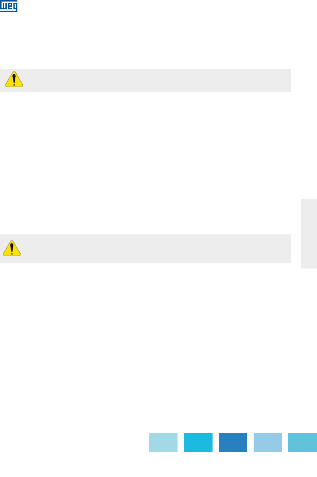
Nas bases metálicas e de concreto pode existir um sistema de deslizamento. Normalmente são utilizados em
aplicações em que o acionamento ocorre por polias e correias. São mais flexíveis permitindo montagens e
desmontagens mais rápidas, além de permitir ajustes na tensão da correia. Outro aspecto importante é a
posição dos parafusos de travamento da base, que devem ser opostos e na diagonal. O trilho mais próximo da
polia motora é colocado de forma que o parafuso de posicionamento fique entre o motor e a máquina
acionada. O outro trilho deve ser colocado com o parafuso na posição oposta (diagonal), como apresentado
na Figura 6.4.
Para facilitar a montagem, as bases podem possuir características como:
g Ressaltos e/ou reentrâncias;
g Parafusos de ancoragem com placas soltas;
g Parafusos fundidos no concreto;
g Parafusos de nivelamento;
g Parafusos de posicionamento;
g Blocos de ferro ou de aço, placas com superfícies planas.
Figura 6.4 - Motor instalado sobre base deslizante.
Recomenda-se também que após a instalação do motor, as partes metálicas expostas sejam protegidas
contra oxidação.
Os motores podem ser montados sobre:
g Bases de concreto: mais recomendadas e usuais para os motores de grande porte (ver Figura 6.2);
g Bases metálicas: mais comuns para motores de pequeno porte (ver Figura 6.3).
Figura 6.3 - Motor instalado sobre base metálica
Figura 6.2 - Motor instalado sobre base de concreto
F1F1
F2F2
A
www.weg.net
Motores Elétricos 27
PORTUGUÊS
6.2. FIXAÇÃO DO MOTOR
6.2.1. Fixação pelos pés
O dimensional da furação dos pés, baseado nas normas IEC ou NEMA, é informado no catálogo técnico do
produto.
O motor deve ser apoiado sobre a base, alinhado e nivelado a fim de que não provoque vibrações e esforços
excessivos no eixo e nos mancais. Para mais detalhes, consultar item 6.3 e 6.6.
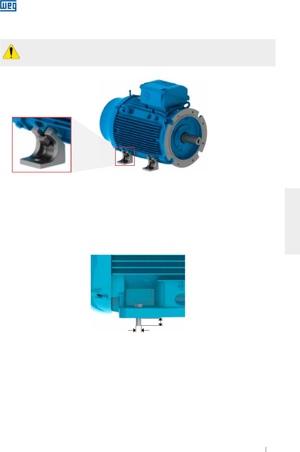
Recomenda-se que o parafuso de fixação tenha comprimento roscado livre de 1,5 vezes o diâmetro do
parafuso. Em aplicações severas, pode ser necessária a utilização de um comprimento roscado livre maior. A
Figura 6.6 representa a fixação do motor com pés indicando o comprimento livre mínimo do parafuso.
Figura 6.6 - Representação da fixação do motor por pés
L = 1.5 x D
D
Motores sem pés fornecidos com dispositivos de transporte, de acordo com a Figura 6.5, devem ter seus
dispositivos retirados antes de iniciar a instalação do motor.
Figura 6.5 - Detalhe do dispositivo de transporte para motores sem pés
www.weg.net
Motores Elétricos28
PORTUGUÊS
6.2.2. Fixação por flange
O dimensional do flange, baseado nas normas IEC ou NEMA, é informado no catálogo eletrônico ou no
catálogo técnico do produto.
O flange do motor deve ser apoiado na base, que deve possuir dimensional de encaixe adequado para o
tamanho do flange do motor, assegurando assim a a concentricidade do conjunto.
Dependendo do tipo do flange, a fixação pode ser realizada do motor para a base (flange FF(IEC) ou D (NEMA))
ou da base para o motor (flange C (DIN ou NEMA)).
Para fixação da base para o motor, a determinação do comprimento do parafuso deve levar em consideração
a espessura da base do usuário e a profundidade da rosca do flange do motor.
Nos casos que a furação do flange é passante, o comprimento do parafuso de fixação do motor
não deve exceder o comprimento roscado do flange, evitando assim contato com a bobina do
motor.
Para fixação do motor à base, recomenda-se que o parafuso de fixação tenha comprimento roscado livre de
1,5 vezes o diâmetro do parafuso. Em aplicações severas, pode ser necessária a utilização de um
comprimento roscado livre maior.
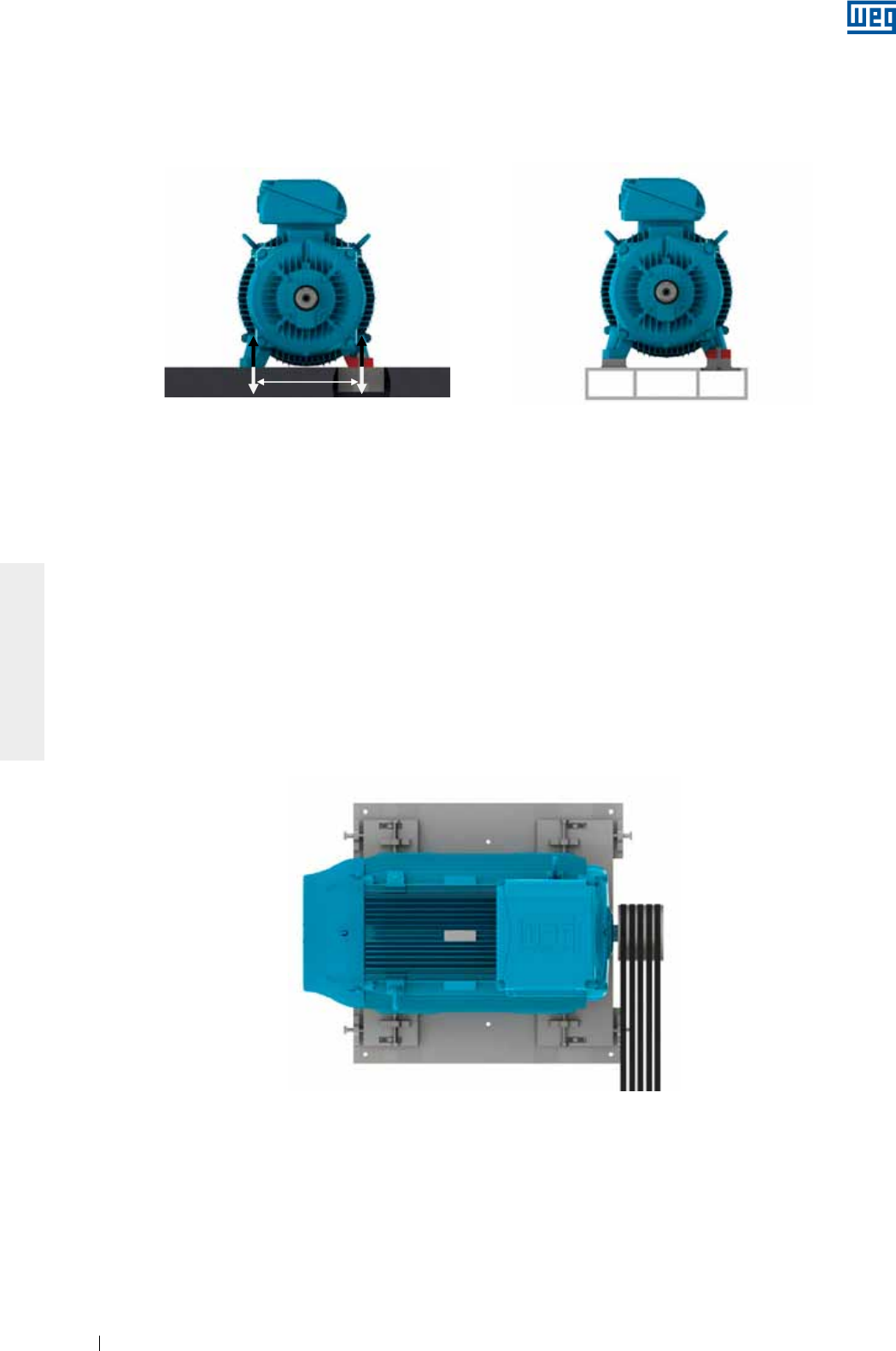
Para fixação de motores de grande porte e/ou em aplicações severas, recomenda-se que além da fixação por
flange, o motor seja apoiado (por pés ou pad). O motor nunca pode ser apoiado sobre suas aletas (ver Figura
6.7).
Figura 6.7 - Representação da fixação do motor com flange e apoio na base da carcaça
Para aplicação de motores com a presença de líquidos no interior do flange (ex.: óleo), a vedação do motor
deve ser adequada para impedir a penetração de líquidos para o interior do motor.
6.2.3. Fixação por
pad
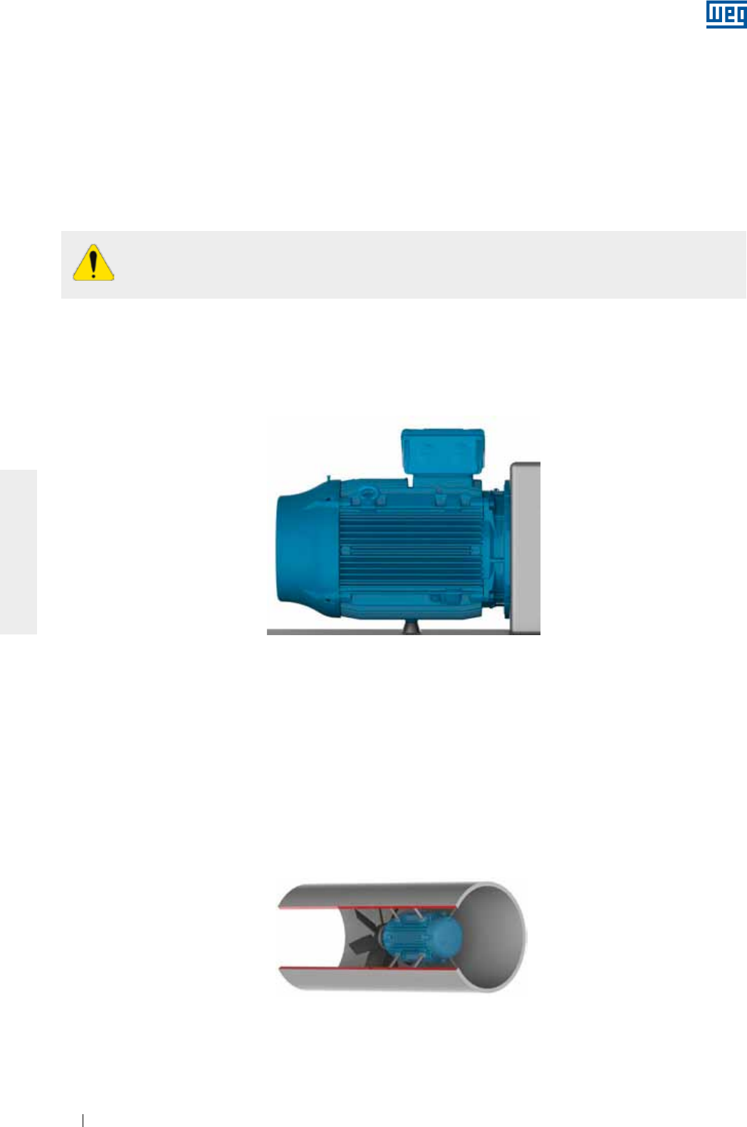
Esse tipo de fixação é normalmente utilizado em dutos de ventilação. A fixação do motor é feita através de
furos roscados na estrutura do motor, cujo dimensional é informado no catálogo eletrônico ou no catálogo
técnico do produto.
O dimensionamento da haste de fixação/parafuso do motor deve levar em consideração o dimensional do duto
de ventilação ou a base de instalação e a profundidade da rosca no motor. As hastes de fixação e a parede do
duto devem ter rigidez suficiente para evitar a vibração excessiva do conjunto (motor e ventilador). A Figura 6.8
representa a fixação por pads.
Figura 6.8 - Representação da fixação do motor no interior de um duto de ventilação
www.weg.net
Motores Elétricos 29
PORTUGUÊS
6.3. BALANCEAMENTO
Equipamentos desbalanceados geram vibrações que podem causar danos ao motor. Os motores WEG são
balanceados dinamicamente com “meia chaveta” em vazio (desacoplados). Balanceamentos especiais devem
ser solicitados no ato da compra.
Os elementos de transmissão tais como polias, acoplamentos, etc., devem ser balanceados antes
de serem instalados nos eixos dos motores.
Motores acionados sem elementos de transmissão acoplados devem ter sua chaveta firmemente
fixa ou removida, para prevenir acidentes.
Em aplicações com acoplamento direto, recomenda-se o uso de rolamentos de esferas.
Uma tensão excessiva nas correias danifica os rolamentos e pode provocar a ruptura do eixo do
motor.
O grau de qualidade de balanceamento do motor segue as normas vigentes para cada linha de produto.
Recomenda-se que os desvios máximos de balanceamento sejam registrados no relatório de instalação.
6.4. ACOPLAMENTOS
6.4.1. Acoplamento direto
Os acoplamentos são utilizados para a transmissão do torque do motor para a máquina acionada. Ao utilizar
um acoplamento, devem ser observados os tópicos a seguir:
g Utilizar ferramentas apropriadas para a montagem e desmontagem dos acoplamentos e assim evitar danos
ao motor;
g Recomenda-se a utilização de acoplamentos flexíveis, capazes de absorver pequenos desalinhamentos
durante a operação do equipamento;
g As cargas máximas e limites de velocidade informados nos catálogos dos fabricantes dos acoplamentos e
do motor não devem ser excedidos;
g Realizar o nivelamento e alinhamento do motor conforme itens 6.5 e 6.6, respectivamente.
O acoplamento direto é caracterizado quando o eixo do motor está acoplado diretamente ao eixo da carga
acionada, sem o uso de elementos de transmissão. O acoplamento direto apresenta menor custo, maior
segurança contra acidentes e ocupa menos espaço.
6.4.2. Acoplamento por engrenagem
O acoplamento por engrenagens é utilizado quando há a necessidade de uma redução de velocidade.
É imprescindível que os eixos estejam perfeitamente alinhados, rigorosamente paralelos (no caso de
engrenagens retas) e no ângulo de engrenamento (no caso de engrenagens cônicas ou helicoidais).
6.4.3. Acoplamento por polias e correias
É um tipo de transmissão utilizado quando há a necessidade de uma relação de velocidades entre o motor e a
carga acionada.
6.4.4. Acoplamento de motores equipados com mancais de deslizamento
Motores equipados com mancais de deslizamento devem estar acoplados diretamente à máquina acionada ou
por meio de um redutor. Mancais de deslizamento não permitem o acoplamento através de polias e correias
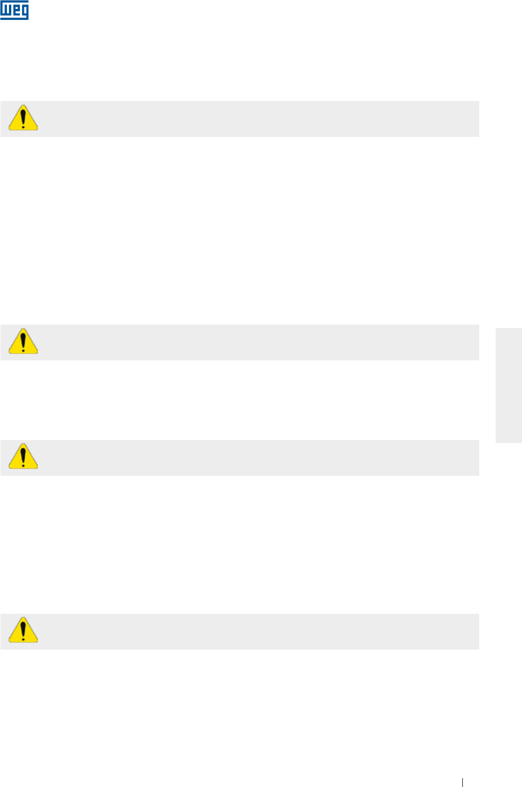
Os motores equipados com mancais de deslizamento possuem 3 (três) marcas na ponta do eixo, sendo que a
marca central é a indicação do centro magnético e as outras 2 (duas) marcas externas indicam os limites de
movimento axial permitidos para o rotor, conforme Figura 6.9.
O motor deve ser acoplado de maneira que a seta fixada na carcaça do mancal fique posicionada sobre a
marca central, quando o motor está em operação. Durante a partida, ou mesmo em operação, o rotor pode
www.weg.net
Motores Elétricos30
PORTUGUÊS
mover-se livremente entre as duas ranhuras externas, caso a máquina acionada exerça algum esforço axial
sobre o eixo do motor. No entanto, em hipótese alguma o motor pode operar de maneira constante com
esforço axial sobre o mancal.
Folga axial
Figura 6.9 - Folga axial em motor equipado com mancal de deslizamento
Ao avaliar o acoplamento, deve-se considerar a folga axial máxima do mancal (conforme Tabela 6.1). As folgas
axiais da máquina acionada e do acoplamento influenciam na folga máxima do mancal.
Tabela 6.1 Folgas utilizadas em mancais de deslizamento
Tamanho do mancal Folga axial total (mm)
9* 3 + 3 = 6
11* 4 + 4 = 8
14* 5 + 5 =10
18 7,5 + 7,5 = 15
* Para motores conforme a norma API 541, a folga axial total é 12,7 mm.
Os mancais de deslizamento utilizados pela WEG não foram projetados para suportar esforço axial contínuo.
Não é recomendada a operação contínua da máquina nos seus limites da folga axial.
6.5. NIVELAMENTO
O nivelamento do motor deve ser realizado para corrigir eventuais desvios de planicidade, que possam existir
provenientes de outros processos e acomodações dos materiais. O nivelamento pode ser feito por meio de
um parafuso de nivelamento fixo no pé ou flange do motor ou por meio de finas chapas de compensação.
Após o nivelamento, a diferença de altura entre a base de fixação do motor e o motor não deve exceder 0,1 mm.
Caso uma base metálica seja utilizada para ajustar a altura da ponta de eixo do motor com a ponta de eixo da
máquina acionada, esta deve ser nivelada na base de concreto.
Recomenda-se que os desvios máximos de nivelamento sejam registrados e armazenados no relatório de
instalação.
6.6. ALINHAMENTO
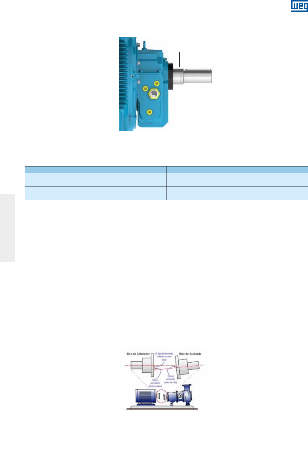
O alinhamento entre a máquina motora e a acionada é uma das variáveis que mais contribuem para prolongar
a vida do motor. O desalinhamento entre os acoplamentos geram elevadas cargas que reduzem a vida útil dos
mancais, provocam vibrações e, em casos extremos, podem causar a ruptura do eixo. A Figura 6.10 ilustra o
desalinhamento entre o motor e o equipamento acionado.
Figura 6.10 - Condição típica de desalinhamento
Para se efetuar um bom alinhamento do motor, devem-se utilizar ferramentas e dispositivos adequados, como
relógio comparador, instrumento de alinhamento a laser, entre outros. O eixo deve ser alinhado axialmente e
radialmente com o eixo da máquina acionada
www.weg.net
Motores Elétricos 31
PORTUGUÊS
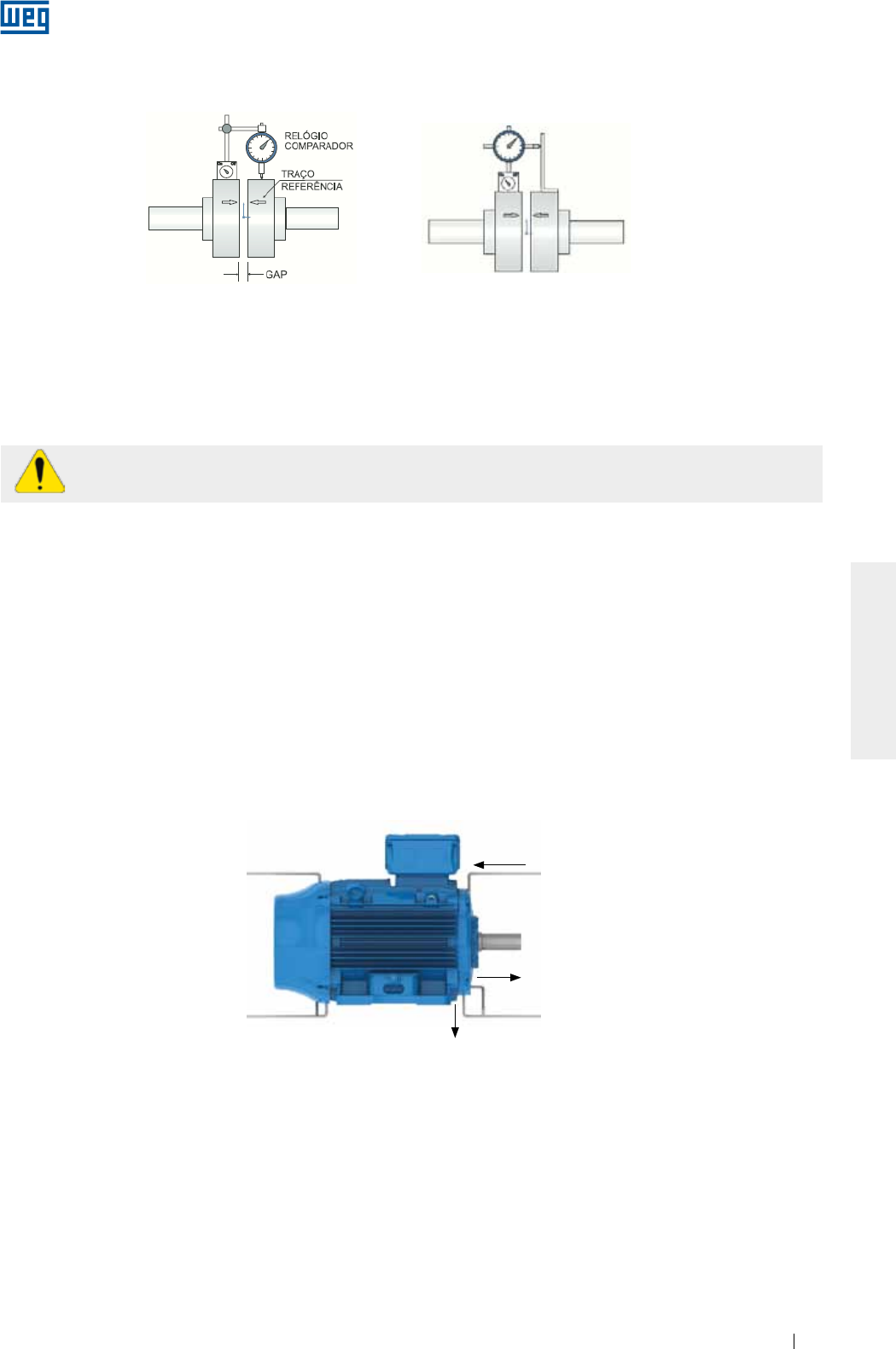
Alinhamento paralelo Alinhamento angular
Figura 6.11 - Alinhamento com relógio comparador
Caso o alinhamento seja realizado através de um instrumento a laser, devem ser seguidas as instruções e
recomendações fornecidas pelo fabricante do instrumento.
A verificação do alinhamento deve ser realizada na temperatura ambiente e na temperatura de trabalho dos
equipamentos.
É recomendado que o alinhamento dos acoplamentos seja verificado periodicamente.
Para acoplamento por polias e correias, o alinhamento deve ser realizado de tal modo que o centro da polia
motora esteja no mesmo plano do centro da polia movida e os eixos do motor e da máquina estejam
perfeitamente paralelos.
Após a realização dos procedimentos descritos anteriormente, deve-se certificar de que os dispositivos de
montagem do motor não permitam alterações no alinhamento e no nivelamento e não causem danos ao
equipamento.
Recomenda-se que os desvios máximos de alinhamento sejam registrados e armazenados no relatório de
instalação.
6.7. CONEXÃO DE MOTORES LUBRIFICADOS A ÓLEO OU DO TIPO
OIL MIST
Nos motores com lubrificação a óleo ou do tipo
oil mist
, deve-se conectar os tubos de lubrificação existentes
(entrada, saída do mancal e dreno do motor), conforme indicado na Figura 6.12.
O sistema de lubrificação deve garantir lubrificação contínua do mancal de acordo com as especificações do
fabricante deste sistema.
Saída
Entrada
Dreno
Figura 6.12 - Sistema de alimentação e drenagem para motores lubrificados por óleo ou do tipo Oil Mist
O valor lido em relógios comparadores para o alinhamento, de acordo com a Figura 6.11, não deve exceder
0,03 mm, considerando um giro completo do eixo. Deve existir uma folga entre os acoplamentos, para
compensar a dilatação térmica dos eixos, conforme especificação do fabricante do acoplamento.
6.8. CONEXÃO DO SISTEMA DE REFRIGERAÇÃO À ÁGUA
Nos motores com refrigeração à água, deve ser prevista a instalação de dutos na entrada e saída de água do
motor para garantir a sua refrigeração. Deve-se observar (conforme item 7.2), a vazão mínima e temperatura da
água na instalação.
6.9. CONEXÃO ELÉTRICA
Para o dimensionamento dos cabos de alimentação e dispositivos de manobra e proteção devem ser
considerados: corrente nominal do motor, fator de serviço, corrente de partida, condições do ambiente e da
instalação, a máxima queda de tensão, etc., conforme as normas vigentes.
Todos os motores devem ser instalados com sistemas de proteção contra sobrecarga. Para motores trifásicos
recomenda-se também a instalação de sistemas de proteção contra falta de fase.
www.weg.net
Motores Elétricos32
PORTUGUÊS
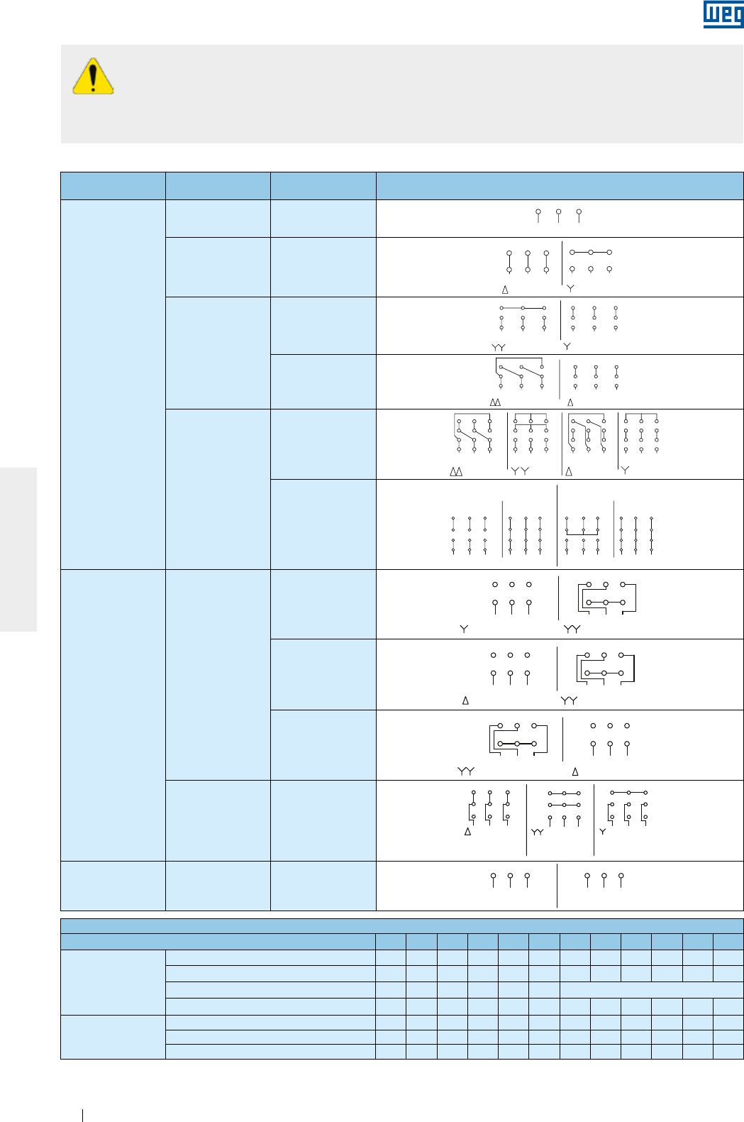
Antes de conectar o motor, verificar se a tensão e a frequência da rede são as mesmas marcadas
na placa de identificação do motor. Seguir o diagrama de ligação indicado na placa de
identificação do motor. Como referência, podem ser seguidos os diagramas de ligação
apresentados na Tabela 6.2.
Para evitar acidentes, verificar se o aterramento foi realizado conforme as normas vigentes.
Distância de isolação
Configuração Quantidade
de cabos Tipo de ligação Diagrama de ligação
Velocidade única
3 -
L1 L2 L3
31 2
L2L1
1
6
L3
2 3
4 5
L2L1
1
6
L3
2 3
4 5
L3L2L1 L3L2L1
5
2
8
7
1
49
3
68
2
5
7
1
49
3
6
45 64
L1
7
1L3
98 32
L2
7
L1
1
65
3
9
L2 L3
2
8
78 9
L3L2
2L1
3
5
11 12
610
1
4
1
32 L3L2 L1
11
5
8
12 10
6
94
71
32 L3L2 L1
11
5
8
12 10
6
94
71
32 L3L2 L1
11
5
8
12 10
6
94
7
L2
4
L1 L2
1 2
6
L3 L1
3
5
L2L3 L1 L3 L1
RUNSTART
12 10
7 8
PART-WINDING
11
9
START
WYE-DELTA
L2 L3
RUN
3
5
9
11
8
4
2
10
1
6
7
12 1012 11
6 4 5
987 321 3
9
5
11
2
8
1
74
10
6
12
1 2
L2L1
6 4
3
L3 L1 L2
5
L3
LOW SPEED HIGH SPEED
LOW SPEED
L1 L3L2 L3
HIGH SPEED
L1 L2
31 2 1 2 3
LOW SPEED L1 L3L2
L3 HIGH SPEED
L1 L2
6
3
4
1
5
2
1 2 3
4 5 6
LOW SPEED
L1 L3L2 L3
HIGH SPEED
L1 L2
6
3
4
1
5
21 2 3
4 5 6
ONLY FOR
STARTING
6
54
L1 L2 L3
87
1 2 9
3
64 5
HIGH SPEED
L1 L2 L3
8
2
7
19
3
LOW SPEED
5
4
L1 L2
8
7
126
L3
9
3
ONLY FOR
STARTING
654
L1 L2 L3
87
1 2 9
3
64 5
HIGH SPEED
L1 L2 L3
8
2
7
19
3
LOW SPEED
5
4
L1 L2
8
7
126
L3
9
3
64 5 4 5 6
L1 L2 L3
31 2
L2L1
1
6
L3
2 3
4 5
L2L1
1
6
L3
2 3
4 5
L3L2L1 L3L2L1
5
2
8
7
1
49
3
68
2
5
7
1
49
3
6
45 64
L1
7
1L3
98 32
L2
7
L1
1
65
3
9
L2 L3
2
8
78 9
L3L2
2L1
3
5
11 12
610
1
4
1
32 L3L2 L1
11
5
8
12 10
6
94
71
32 L3L2 L1
11
5
8
12 10
6
94
71
32 L3L2 L1
11
5
8
12 10
6
94
7
L2
4
L1 L2
1 2
6
L3 L1
3
5
L2L3 L1 L3 L1
12 10
7 8 11
9
L2 L3
3
5
9
11
8
4
2
10
1
6
7
12 1012 11
6 4 5
987 321 3
9
5
11
2
8
1
74
10
6
12
1 2
L2L1
6 4
3
L3 L1 L2
5
L3
L1 L3L2 L3L1 L2
31 2 1 2 3
L1 L3L2
L3L1 L2
6
3
4
1
5
2
1 2 3
4 5 6
L1 L3L2 L3L1 L2
6
3
4
1
5
21 2 3
4 5 6
654
L1 L2 L3
87
1 2 9
3
64 5
L1 L2 L3
8
2
7
19
3
5
4
L1 L2
8
7
126
L3
9
3654
L1 L2 L3
87
1 2 9
3
64 5
L1 L2 L3
8
2
7
19
3
5
4
L1 L2
8
7
126
L3
9
3
64 5 4 5 6
OPERAÇÃOPARTIDA OPERAÇÃOPARTIDA
PART-WINDING ESTRELA-TRIÂNGULO
MENOR ROTAÇÃO
MENOR ROTAÇÃO
MENOR
ROTAÇÃO
MENOR ROTAÇÃO MAIOR ROTAÇÃO
MAIOR ROTAÇÃO
MAIOR ROTAÇÃO
MENOR ROTAÇÃO MAIOR ROTAÇÃO
MAIOR
ROTAÇÃO SOMENTE
PARTIDA
L1 L2 L3
31 2
L2L1
1
6
L3
2 3
4 5
L2L1
1
6
L3
2 3
4 5
L3L2L1 L3L2L1
5
2
8
7
1
49
3
68
2
5
7
1
49
3
6
45 64
L1
7
1L3
98 32
L2
7
L1
1
65
3
9
L2 L3
2
8
78 9
L3L2
2L1
3
5
11 12
610
1
4
1
32 L3L2 L1
11
5
8
12 10
6
94
71
32 L3L2 L1
11
5
8
12 10
6
94
71
32 L3L2 L1
11
5
8
12 10
6
94
7
L2
4
L1 L2
1 2
6
L3 L1
3
5
L2L3 L1 L3 L1
12 10
7 8 11
9
L2 L3
3
5
9
11
8
4
2
10
1
6
7
12 1012 11
6 4 5
987 321 3
9
5
11
2
8
1
74
10
6
12
1 2
L2L1
6 4
3
L3 L1 L2
5
L3
L1 L3L2 L3L1 L2
31 2 1 2 3
L1 L3L2
L3L1 L2
6
3
4
1
5
2
1 2 3
1 2 3
4 5 6
L1 L3L2 L3L1 L2
6
3
4
1
5
21 2 3
4 5 6
654
L1 L2 L3
87
1 2 9
3
64 5
L1 L2 L3
8
2
7
19
3
5
4
L1 L2
8
7
6
L3
9
654
L1 L2 L3
87
1 2 9
3
64 5
L1 L2 L3
8
2
7
19
3
5
4
L1 L2
8
7
6
L3
9
64 5 4 5 6
PART-WINDING
OPERACIÓNARRANQUE OPERACIÓNARRANQUE
ESTRELLA - TRIÁNGULO
MENOR ROTACIÓN MAYOR ROTACIÓN
MENOR ROTACIÓN
MENOR ROTACIÓN
MENOR ROTACIÓN
MAYOR ROTACIÓN
MAYOR ROTACIÓN
MAYOR ROTACIÓN
SÓLO PARA
ARRANQUE
MAYOR
ROTACIÓN
MENOR
ROTACIÓN
6Δ - Y
L1 L2 L3
31 2
L2L1
1
6
L3
2 3
4 5
L2L1
1
6
L3
2 3
4 5
L3L2L1 L3L2L1
5
2
8
7
1
49
3
68
2
5
7
1
49
3
6
45 64
L1
7
1L3
98 32
L2
7
L1
1
65
3
9
L2 L3
2
8
78 9
L3L2
2L1
3
5
11 12
610
1
4
1
32 L3L2 L1
11
5
8
12 10
6
94
71
32 L3L2 L1
11
5
8
12 10
6
94
71
32 L3L2 L1
11
5
8
12 10
6
94
7
L2
4
L1 L2
1 2
6
L3 L1
3
5
L2L3 L1 L3 L1
RUNSTART
12 10
7 8
PART-WINDING
11
9
START
WYE-DELTA
L2 L3
RUN
3
5
9
11
8
4
2
10
1
6
7
12 1012 11
6 4 5
987 321 3
9
5
11
2
8
1
74
10
6
12
1 2
L2L1
6 4
3
L3 L1 L2
5
L3
LOW SPEED HIGH SPEED
LOW SPEED
L1 L3L2 L3
HIGH SPEED
L1 L2
31 2 1 2 3
LOW SPEED L1 L3L2
L3 HIGH SPEED
L1 L2
6
3
4
1
5
2
1 2 3
4 5 6
LOW SPEED
L1 L3L2 L3
HIGH SPEED
L1 L2
6
3
4
1
5
21 2 3
4 5 6
ONLY FOR
STARTING
6
54
L1 L2 L3
87
1 2 9
3
64 5
HIGH SPEED
L1 L2 L3
8
2
7
19
3
LOW SPEED
5
4
L1 L2
8
7
126
L3
9
3
ONLY FOR
STARTING
654
L1 L2 L3
87
1 2 9
3
64 5
HIGH SPEED
L1 L2 L3
8
2
7
19
3
LOW SPEED
5
4
L1 L2
8
7
126
L3
9
3
64 5 4 5 6
L1 L2 L3
31 2
L2L1
1
6
L3
2 3
4 5
L2L1
1
6
L3
2 3
4 5
L3L2L1 L3L2L1
5
2
8
7
1
49
3
68
2
5
7
1
49
3
6
45 64
L1
7
1L3
98 32
L2
7
L1
1
65
3
9
L2 L3
2
8
78 9
L3L2
2L1
3
5
11 12
610
1
4
1
32 L3L2 L1
11
5
8
12 10
6
94
71
32 L3L2 L1
11
5
8
12 10
6
94
71
32 L3L2 L1
11
5
8
12 10
6
94
7
L2
4
L1 L2
1 2
6
L3 L1
3
5
L2L3 L1 L3 L1
12 10
7 8 11
9
L2 L3
3
5
9
11
8
4
2
10
1
6
7
12 1012 11
6 4 5
987 321 3
9
5
11
2
8
1
74
10
6
12
1 2
L2L1
6 4
3
L3 L1 L2
5
L3
L1 L3L2 L3L1 L2
31 2 1 2 3
L1 L3L2
L3L1 L2
6
3
4
1
5
2
1 2 3
4 5 6
L1 L3L2 L3L1 L2
6
3
4
1
5
21 2 3
4 5 6
654
L1 L2 L3
87
1 2 9
3
64 5
L1 L2 L3
8
2
7
19
3
5
4
L1 L2
8
7
126
L3
9
3654
L1 L2 L3
87
1 2 9
3
64 5
L1 L2 L3
8
2
7
19
3
5
4
L1 L2
8
7
126
L3
9
3
64 5 4 5 6
OPERAÇÃOPARTIDA OPERAÇÃOPARTIDA
PART-WINDING ESTRELA-TRIÂNGULO
MENOR ROTAÇÃO
MENOR ROTAÇÃO
MENOR
ROTAÇÃO
MENOR ROTAÇÃO MAIOR ROTAÇÃO
MAIOR ROTAÇÃO
MAIOR ROTAÇÃO
MENOR ROTAÇÃO MAIOR ROTAÇÃO
MAIOR
ROTAÇÃO SOMENTE
PARTIDA
L1 L2 L3
31 2
L2L1
1
6
L3
2 3
4 5
L2L1
1
6
L3
2 3
4 5
L3L2L1 L3L2L1
5
2
8
7
1
49
3
68
2
5
7
1
49
3
6
45 64
L1
7
1L3
98 32
L2
7
L1
1
65
3
9
L2 L3
2
8
78 9
L3L2
2L1
3
5
11 12
610
1
4
1
32 L3L2 L1
11
5
8
12 10
6
94
71
32 L3L2 L1
11
5
8
12 10
6
94
71
32 L3L2 L1
11
5
8
12 10
6
94
7
L2
4
L1 L2
1 2
6
L3 L1
3
5
L2L3 L1 L3 L1
12 10
7 8 11
9
L2 L3
3
5
9
11
8
4
2
10
1
6
7
12 1012 11
6 4 5
987 321 3
9
5
11
2
8
1
74
10
6
12
1 2
L2L1
6 4
3
L3 L1 L2
5
L3
L1 L3L2 L3L1 L2
31 2 1 2 3
L1 L3L2
L3L1 L2
6
3
4
1
5
2
1 2 3
1 2 3
4 5 6
L1 L3L2 L3L1 L2
6
3
4
1
5
21 2 3
4 5 6
654
L1 L2 L3
87
1 2 9
3
64 5
L1 L2 L3
8
2
7
19
3
5
4
L1 L2
8
7
6
L3
9
654
L1 L2 L3
87
1 2 9
3
64 5
L1 L2 L3
8
2
7
19
3
5
4
L1 L2
8
7
6
L3
9
64 5 4 5 6
PART-WINDING
OPERACIÓNARRANQUE OPERACIÓNARRANQUE
ESTRELLA - TRIÁNGULO
MENOR ROTACIÓN MAYOR ROTACIÓN
MENOR ROTACIÓN
MENOR ROTACIÓN
MENOR ROTACIÓN
MAYOR ROTACIÓN
MAYOR ROTACIÓN
MAYOR ROTACIÓN
SÓLO PARA
ARRANQUE
MAYOR
ROTACIÓN
MENOR
ROTACIÓN
9
YY - Y
L1 L2 L3
31 2
L2L1
1
6
L3
2 3
4 5
L2L1
1
6
L3
2 3
4 5
L3L2L1 L3L2L1
5
2
8
7
1
4
9
3
6
8
2
5
7
1
4
9
3
6
45 64
L1
7
1L3
98 32
L2
7
L1
1
65
3
9
L2 L3
2
8
78 9
L3L2
2L1
3
5
11 12
610
1
4
1
32 L3L2 L1
11
5
8
12 10
6
94
71
32 L3L2 L1
11
5
8
12 10
6
94
71
32 L3L2 L1
11
5
8
12 10
6
94
7
L2
4
L1 L2
1 2
6
L3 L1
3
5
L2L3 L1 L3 L1
RUNSTART
12 10
7 8
PART-WINDING
11
9
START
WYE-DELTA
L2 L3
RUN
3
5
9
11
8
4
2
10
1
6
7
12 1012 11
6 4 5
987 321 3
9
5
11
2
8
1
74
10
6
12
1 2
L2L1
6 4
3
L3 L1 L2
5
L3
LOW SPEED HIGH SPEED
LOW SPEED
L1 L3L2 L3
HIGH SPEED
L1 L2
31 2 1 2 3
LOW SPEED L1 L3L2
L3 HIGH SPEED
L1 L2
6
3
4
1
5
2
1 2 3
4 5 6
LOW SPEED
L1 L3L2 L3
HIGH SPEED
L1 L2
6
3
4
1
5
21 2 3
4 5 6
ONLY FOR
STARTING
6
54
L1 L2 L3
87
1 2 9
3
64 5
HIGH SPEED
L1 L2 L3
8
2
7
19
3
LOW SPEED
5
4
L1 L2
8
7
126
L3
9
3
ONLY FOR
STARTING
654
L1 L2 L3
87
1 2 9
3
64 5
HIGH SPEED
L1 L2 L3
8
2
7
19
3
LOW SPEED
5
4
L1 L2
8
7
126
L3
9
3
64 5 4 5 6
L1 L2 L3
31 2
L2L1
1
6
L3
2 3
4 5
L2L1
1
6
L3
2 3
4 5
L3L2L1 L3L2L1
5
2
8
7
1
49
3
68
2
5
7
1
49
3
6
45 64
L1
7
1L3
98 32
L2
7
L1
1
65
3
9
L2 L3
2
8
78 9
L3L2
2L1
3
5
11 12
610
1
4
1
32 L3L2 L1
11
5
8
12 10
6
94
71
32 L3L2 L1
11
5
8
12 10
6
94
71
32 L3L2 L1
11
5
8
12 10
6
94
7
L2
4
L1 L2
1 2
6
L3 L1
3
5
L2L3 L1 L3 L1
12 10
7 8 11
9
L2 L3
3
5
9
11
8
4
2
10
1
6
7
12 1012 11
6 4 5
987 321 3
9
5
11
2
8
1
74
10
6
12
1 2
L2L1
6 4
3
L3 L1 L2
5
L3
L1 L3L2 L3L1 L2
31 2 1 2 3
L1 L3L2
L3L1 L2
6
3
4
1
5
2
1 2 3
4 5 6
L1 L3L2 L3L1 L2
6
3
4
1
5
21 2 3
4 5 6
654
L1 L2 L3
87
1 2 9
3
64 5
L1 L2 L3
8
2
7
19
3
5
4
L1 L2
8
7
126
L3
9
3654
L1 L2 L3
87
1 2 9
3
64 5
L1 L2 L3
8
2
7
19
3
5
4
L1 L2
8
7
126
L3
9
3
64 5 4 5 6
OPERAÇÃOPARTIDA OPERAÇÃOPARTIDA
PART-WINDING ESTRELA-TRIÂNGULO
MENOR ROTAÇÃO
MENOR ROTAÇÃO
MENOR
ROTAÇÃO
MENOR ROTAÇÃO MAIOR ROTAÇÃO
MAIOR ROTAÇÃO
MAIOR ROTAÇÃO
MENOR ROTAÇÃO MAIOR ROTAÇÃO
MAIOR
ROTAÇÃO SOMENTE
PARTIDA
L1 L2 L3
31 2
L2L1
1
6
L3
2 3
4 5
L2L1
1
6
L3
2 3
4 5
L3L2L1 L3L2L1
5
2
8
7
1
49
3
68
2
5
7
1
49
3
6
45 64
L1
7
1L3
98 32
L2
7
L1
1
65
3
9
L2 L3
2
8
78 9
L3L2
2L1
3
5
11 12
610
1
4
1
32 L3L2 L1
11
5
8
12 10
6
94
71
32 L3L2 L1
11
5
8
12 10
6
94
71
32 L3L2 L1
11
5
8
12 10
6
94
7
L2
4
L1 L2
1 2
6
L3 L1
3
5
L2L3 L1 L3 L1
12 10
7 8 11
9
L2 L3
3
5
9
11
8
4
2
10
1
6
7
12 1012 11
6 4 5
987 321 3
9
5
11
2
8
1
74
10
6
12
1 2
L2L1
6 4
3
L3 L1 L2
5
L3
L1 L3L2 L3L1 L2
31 2 1 2 3
L1 L3L2
L3L1 L2
6
3
4
1
5
2
1 2 3
1 2 3
4 5 6
L1 L3L2 L3L1 L2
6
3
4
1
5
21 2 3
4 5 6
654
L1 L2 L3
87
1 2 9
3
64 5
L1 L2 L3
8
2
7
19
3
5
4
L1 L2
8
7
6
L3
9
654
L1 L2 L3
87
1 2 9
3
64 5
L1 L2 L3
8
2
7
19
3
5
4
L1 L2
8
7
6
L3
9
64 5 4 5 6
PART-WINDING
OPERACIÓNARRANQUE OPERACIÓNARRANQUE
ESTRELLA - TRIÁNGULO
MENOR ROTACIÓN MAYOR ROTACIÓN
MENOR ROTACIÓN
MENOR ROTACIÓN
MENOR ROTACIÓN
MAYOR ROTACIÓN
MAYOR ROTACIÓN
MAYOR ROTACIÓN
SÓLO PARA
ARRANQUE
MAYOR
ROTACIÓN
MENOR
ROTACIÓN
ΔΔ - Δ
L1 L2 L3
31 2
L2L1
1
6
L3
2 3
4 5
L2L1
1
6
L3
2 3
4 5
L3L2L1 L3L2L1
5
2
8
7
1
49
3
68
2
5
7
1
49
3
6
45 64
L1
7
1L3
98 32
L2
7
L1
1
65
3
9
L2 L3
2
8
78 9
L3L2
2L1
3
5
11 12
610
1
4
1
32 L3L2 L1
11
5
8
12 10
6
94
71
32 L3L2 L1
11
5
8
12 10
6
94
71
32 L3L2 L1
11
5
8
12 10
6
94
7
L2
4
L1 L2
1 2
6
L3 L1
3
5
L2L3 L1 L3 L1
RUNSTART
12 10
7 8
PART-WINDING
11
9
START
WYE-DELTA
L2 L3
RUN
3
5
9
11
8
4
2
10
1
6
7
12 1012 11
6 4 5
987 321 3
9
5
11
2
8
1
74
10
6
12
1 2
L2L1
6 4
3
L3 L1 L2
5
L3
LOW SPEED HIGH SPEED
LOW SPEED
L1 L3L2 L3
HIGH SPEED
L1 L2
31 2 1 2 3
LOW SPEED L1 L3L2
L3 HIGH SPEED
L1 L2
6
3
4
1
5
2
1 2 3
4 5 6
LOW SPEED
L1 L3L2 L3
HIGH SPEED
L1 L2
6
3
4
1
5
21 2 3
4 5 6
ONLY FOR
STARTING
6
54
L1 L2 L3
87
1 2 9
3
64 5
HIGH SPEED
L1 L2 L3
8
2
7
19
3
LOW SPEED
5
4
L1 L2
8
7
126
L3
9
3
ONLY FOR
STARTING
654
L1 L2 L3
87
1 2 9
3
64 5
HIGH SPEED
L1 L2 L3
8
2
7
19
3
LOW SPEED
5
4
L1 L2
8
7
126
L3
9
3
64 5 4 5 6
L1 L2 L3
31 2
L2L1
1
6
L3
2 3
4 5
L2L1
1
6
L3
2 3
4 5
L3L2L1 L3L2L1
5
2
8
7
1
49
3
68
2
5
7
1
49
3
6
45 64
L1
7
1L3
98 32
L2
7
L1
1
65
3
9
L2 L3
2
8
78 9
L3L2
2L1
3
5
11 12
610
1
4
1
32 L3L2 L1
11
5
8
12 10
6
94
71
32 L3L2 L1
11
5
8
12 10
6
94
71
32 L3L2 L1
11
5
8
12 10
6
94
7
L2
4
L1 L2
1 2
6
L3 L1
3
5
L2L3 L1 L3 L1
12 10
7 8 11
9
L2 L3
3
5
9
11
8
4
2
10
1
6
7
12 1012 11
6 4 5
987 321 3
9
5
11
2
8
1
74
10
6
12
1 2
L2L1
6 4
3
L3 L1 L2
5
L3
L1 L3L2 L3L1 L2
31 2 1 2 3
L1 L3L2
L3L1 L2
6
3
4
1
5
2
1 2 3
4 5 6
L1 L3L2 L3L1 L2
6
3
4
1
5
21 2 3
4 5 6
654
L1 L2 L3
87
1 2 9
3
64 5
L1 L2 L3
8
2
7
19
3
5
4
L1 L2
8
7
126
L3
9
3654
L1 L2 L3
87
1 2 9
3
64 5
L1 L2 L3
8
2
7
19
3
5
4
L1 L2
8
7
126
L3
9
3
64 5 4 5 6
OPERAÇÃOPARTIDA OPERAÇÃOPARTIDA
PART-WINDING ESTRELA-TRIÂNGULO
MENOR ROTAÇÃO
MENOR ROTAÇÃO
MENOR
ROTAÇÃO
MENOR ROTAÇÃO MAIOR ROTAÇÃO
MAIOR ROTAÇÃO
MAIOR ROTAÇÃO
MENOR ROTAÇÃO MAIOR ROTAÇÃO
MAIOR
ROTAÇÃO SOMENTE
PARTIDA
L1 L2 L3
31 2
L2L1
1
6
L3
2 3
4 5
L2L1
1
6
L3
2 3
4 5
L3L2L1 L3L2L1
5
2
8
7
1
49
3
68
2
5
7
1
49
3
6
45 64
L1
7
1L3
98 32
L2
7
L1
1
65
3
9
L2 L3
2
8
78 9
L3L2
2L1
3
5
11 12
610
1
4
1
32 L3L2 L1
11
5
8
12 10
6
94
71
32 L3L2 L1
11
5
8
12 10
6
94
71
32 L3L2 L1
11
5
8
12 10
6
94
7
L2
4
L1 L2
1 2
6
L3 L1
3
5
L2L3 L1 L3 L1
12 10
7 8 11
9
L2 L3
3
5
9
11
8
4
2
10
1
6
7
12 1012 11
6 4 5
987 321 3
9
5
11
2
8
1
74
10
6
12
1 2
L2L1
6 4
3
L3 L1 L2
5
L3
L1 L3L2 L3L1 L2
31 2 1 2 3
L1 L3L2
L3L1 L2
6
3
4
1
5
2
1 2 3
1 2 3
4 5 6
L1 L3L2 L3L1 L2
6
3
4
1
5
21 2 3
4 5 6
654
L1 L2 L3
87
1 2 9
3
64 5
L1 L2 L3
8
2
7
19
3
5
4
L1 L2
8
7
6
L3
9
654
L1 L2 L3
87
1 2 9
3
64 5
L1 L2 L3
8
2
7
19
3
5
4
L1 L2
8
7
6
L3
9
64 5 4 5 6
PART-WINDING
OPERACIÓNARRANQUE OPERACIÓNARRANQUE
ESTRELLA - TRIÁNGULO
MENOR ROTACIÓN MAYOR ROTACIÓN
MENOR ROTACIÓN
MENOR ROTACIÓN
MENOR ROTACIÓN
MAYOR ROTACIÓN
MAYOR ROTACIÓN
MAYOR ROTACIÓN
SÓLO PARA
ARRANQUE
MAYOR
ROTACIÓN
MENOR
ROTACIÓN
12
ΔΔ - YY - Δ - Y
L1 L2 L3
31 2
L2L1
1
6
L3
2 3
4 5
L2L1
1
6
L3
2 3
4 5
L3L2L1 L3L2L1
5
2
8
7
1
49
3
68
2
5
7
1
49
3
6
45 64
L1
7
1L3
98 32
L2
7
L1
1
65
3
9
L2 L3
2
8
78 9
L3L2
2L1
3
5
11 12
610
1
4
1
32 L3L2 L1
11
5
8
12 10
6
94
71
32 L3L2 L1
11
5
8
12 10
6
94
71
32 L3L2 L1
11
5
8
12 10
6
94
7
L2
4
L1 L2
1 2
6
L3 L1
3
5
L2L3 L1 L3 L1
RUNSTART
12 10
7 8
PART-WINDING
11
9
START
WYE-DELTA
L2 L3
RUN
3
5
9
11
8
4
2
10
1
6
7
12 1012 11
6 4 5
987 321 3
9
5
11
2
8
1
74
10
6
12
1 2
L2L1
6 4
3
L3 L1 L2
5
L3
LOW SPEED HIGH SPEED
LOW SPEED
L1 L3L2 L3
HIGH SPEED
L1 L2
31 2 1 2 3
LOW SPEED L1 L3L2
L3 HIGH SPEED
L1 L2
6
3
4
1
5
2
1 2 3
4 5 6
LOW SPEED
L1 L3L2 L3
HIGH SPEED
L1 L2
6
3
4
1
5
21 2 3
4 5 6
ONLY FOR
STARTING
6
54
L1 L2 L3
87
1 2 9
3
64 5
HIGH SPEED
L1 L2 L3
8
2
7
19
3
LOW SPEED
5
4
L1 L2
8
7
126
L3
9
3
ONLY FOR
STARTING
654
L1 L2 L3
87
1 2 9
3
64 5
HIGH SPEED
L1 L2 L3
8
2
7
19
3
LOW SPEED
5
4
L1 L2
8
7
126
L3
9
3
64 5 4 5 6
L1 L2 L3
31 2
L2L1
1
6
L3
2 3
4 5
L2L1
1
6
L3
2 3
4 5
L3L2L1 L3L2L1
5
2
8
7
1
49
3
68
2
5
7
1
49
3
6
45 64
L1
7
1L3
98 32
L2
7
L1
1
65
3
9
L2 L3
2
8
78 9
L3L2
2L1
3
5
11 12
610
1
4
1
32 L3L2 L1
11
5
8
12 10
6
94
71
32 L3L2 L1
11
5
8
12 10
6
94
71
32 L3L2 L1
11
5
8
12 10
6
94
7
L2
4
L1 L2
1 2
6
L3 L1
3
5
L2L3 L1 L3 L1
12 10
7 8 11
9
L2 L3
3
5
9
11
8
4
2
10
1
6
7
12 1012 11
6 4 5
987 321 3
9
5
11
2
8
1
74
10
6
12
1 2
L2L1
6 4
3
L3 L1 L2
5
L3
L1 L3L2 L3L1 L2
31 2 1 2 3
L1 L3L2
L3L1 L2
6
3
4
1
5
2
1 2 3
4 5 6
L1 L3L2 L3L1 L2
6
3
4
1
5
21 2 3
4 5 6
654
L1 L2 L3
87
1 2 9
3
64 5
L1 L2 L3
8
2
7
19
3
5
4
L1 L2
8
7
126
L3
9
3654
L1 L2 L3
87
1 2 9
3
64 5
L1 L2 L3
8
2
7
19
3
5
4
L1 L2
8
7
126
L3
9
3
64 5 4 5 6
OPERAÇÃOPARTIDA OPERAÇÃOPARTIDA
PART-WINDING ESTRELA-TRIÂNGULO
MENOR ROTAÇÃO
MENOR ROTAÇÃO
MENOR
ROTAÇÃO
MENOR ROTAÇÃO MAIOR ROTAÇÃO
MAIOR ROTAÇÃO
MAIOR ROTAÇÃO
MENOR ROTAÇÃO MAIOR ROTAÇÃO
MAIOR
ROTAÇÃO SOMENTE
PARTIDA
L1 L2 L3
31 2
L2L1
1
6
L3
2 3
4 5
L2L1
1
6
L3
2 3
4 5
L3L2L1 L3L2L1
5
2
8
7
1
49
3
68
2
5
7
1
49
3
6
45 64
L1
7
1L3
98 32
L2
7
L1
1
65
3
9
L2 L3
2
8
78 9
L3L2
2L1
3
5
11 12
610
1
4
1
32 L3L2 L1
11
5
8
12 10
6
94
71
32 L3L2 L1
11
5
8
12 10
6
94
71
32 L3L2 L1
11
5
8
12 10
6
94
7
L2
4
L1 L2
1 2
6
L3 L1
3
5
L2L3 L1 L3 L1
12 10
7 8 11
9
L2 L3
3
5
9
11
8
4
2
10
1
6
7
12 1012 11
6 4 5
987 321 3
9
5
11
2
8
1
74
10
6
12
1 2
L2L1
6 4
3
L3 L1 L2
5
L3
L1 L3L2 L3L1 L2
31 2 1 2 3
L1 L3L2
L3L1 L2
6
3
4
1
5
2
1 2 3
1 2 3
4 5 6
L1 L3L2 L3L1 L2
6
3
4
1
5
21 2 3
4 5 6
654
L1 L2 L3
87
1 2 9
3
64 5
L1 L2 L3
8
2
7
19
3
5
4
L1 L2
8
7
6
L3
9
654
L1 L2 L3
87
1 2 9
3
64 5
L1 L2 L3
8
2
7
19
3
5
4
L1 L2
8
7
6
L3
9
64 5 4 5 6
PART-WINDING
OPERACIÓNARRANQUE OPERACIÓNARRANQUE
ESTRELLA - TRIÁNGULO
MENOR ROTACIÓN MAYOR ROTACIÓN
MENOR ROTACIÓN
MENOR ROTACIÓN
MENOR ROTACIÓN
MAYOR ROTACIÓN
MAYOR ROTACIÓN
MAYOR ROTACIÓN
SÓLO PARA
ARRANQUE
MAYOR
ROTACIÓN
MENOR
ROTACIÓN
Δ - PWS
Partida
Part-winding
L1 L2 L3
31 2
L2L1
1
6
L3
2 3
4 5
L2L1
1
6
L3
2 3
4 5
L3L2L1 L3L2L1
5
2
8
7
1
49
3
68
2
5
7
1
49
3
6
45 64
L1
7
1L3
98 32
L2
7
L1
1
65
3
9
L2 L3
2
8
78 9
L3L2
2L1
3
5
11 12
610
1
4
1
32 L3L2 L1
11
5
8
12 10
6
94
71
32 L3L2 L1
11
5
8
12 10
6
94
71
32 L3L2 L1
11
5
8
12 10
6
94
7
L2
4
L1 L2
1 2
6
L3 L1
3
5
L2L3 L1 L3 L1
RUNSTART
12 10
7 8
PART-WINDING
11
9
START
WYE-DELTA
L2 L3
RUN
3
5
9
11
8
4
2
10
1
6
7
12 1012 11
6 4 5
987 321 3
9
5
11
2
8
1
74
10
6
12
1 2
L2L1
6 4
3
L3 L1 L2
5
L3
LOW SPEED HIGH SPEED
LOW SPEED
L1 L3L2 L3
HIGH SPEED
L1 L2
31 2 1 2 3
LOW SPEED L1 L3L2
L3 HIGH SPEED
L1 L2
6
3
4
1
5
2
1 2 3
4 5 6
LOW SPEED
L1 L3L2 L3
HIGH SPEED
L1 L2
6
3
4
1
5
21 2 3
4 5 6
ONLY FOR
STARTING
6
54
L1 L2 L3
87
1 2 9
3
64 5
HIGH SPEED
L1 L2 L3
8
2
7
19
3
LOW SPEED
5
4
L1 L2
8
7
126
L3
9
3
ONLY FOR
STARTING
654
L1 L2 L3
87
1 2 9
3
64 5
HIGH SPEED
L1 L2 L3
8
2
7
19
3
LOW SPEED
5
4
L1 L2
8
7
126
L3
9
3
64 5 4 5 6
L1 L2 L3
31 2
L2L1
1
6
L3
2 3
4 5
L2L1
1
6
L3
2 3
4 5
L3L2L1 L3L2L1
5
2
8
7
1
49
3
68
2
5
7
1
49
3
6
45 64
L1
7
1L3
98 32
L2
7
L1
1
65
3
9
L2 L3
2
8
78 9
L3L2
2L1
3
5
11 12
610
1
4
1
32 L3L2 L1
11
5
8
12 10
6
94
71
32 L3L2 L1
11
5
8
12 10
6
94
71
32 L3L2 L1
11
5
8
12 10
6
94
7
L2
4
L1 L2
1 2
6
L3 L1
3
5
L2L3 L1 L3 L1
12 10
7 8 11
9
L2 L3
3
5
9
11
8
4
2
10
1
6
7
12 1012 11
6 4 5
987 321 3
9
5
11
2
8
1
74
10
6
12
1 2
L2L1
6 4
3
L3 L1 L2
5
L3
L1 L3L2 L3L1 L2
31 2 1 2 3
L1 L3L2
L3L1 L2
6
3
4
1
5
2
1 2 3
4 5 6
L1 L3L2 L3L1 L2
6
3
4
1
5
21 2 3
4 5 6
654
L1 L2 L3
87
1 2 9
3
64 5
L1 L2 L3
8
2
7
19
3
5
4
L1 L2
8
7
126
L3
9
3654
L1 L2 L3
87
1 2 9
3
64 5
L1 L2 L3
8
2
7
19
3
5
4
L1 L2
8
7
126
L3
9
3
64 5 4 5 6
OPERAÇÃOPARTIDA OPERAÇÃOPARTIDA
PART-WINDING ESTRELA-TRIÂNGULO
MENOR ROTAÇÃO
MENOR ROTAÇÃO
MENOR
ROTAÇÃO
MENOR ROTAÇÃO MAIOR ROTAÇÃO
MAIOR ROTAÇÃO
MAIOR ROTAÇÃO
MENOR ROTAÇÃO MAIOR ROTAÇÃO
MAIOR
ROTAÇÃO SOMENTE
PARTIDA
L1 L2 L3
31 2
L2L1
1
6
L3
2 3
4 5
L2L1
1
6
L3
2 3
4 5
L3L2L1 L3L2L1
5
2
8
7
1
49
3
68
2
5
7
1
49
3
6
45 64
L1
7
1L3
98 32
L2
7
L1
1
65
3
9
L2 L3
2
8
78 9
L3L2
2L1
3
5
11 12
610
1
4
1
32 L3L2 L1
11
5
8
12 10
6
94
71
32 L3L2 L1
11
5
8
12 10
6
94
71
32 L3L2 L1
11
5
8
12 10
6
94
7
L2
4
L1 L2
1 2
6
L3 L1
3
5
L2L3 L1 L3 L1
12 10
7 8 11
9
L2 L3
3
5
9
11
8
4
2
10
1
6
7
12 1012 11
6 4 5
987 321 3
9
5
11
2
8
1
74
10
6
12
1 2
L2L1
6 4
3
L3 L1 L2
5
L3
L1 L3L2 L3L1 L2
31 2 1 2 3
L1 L3L2
L3L1 L2
6
3
4
1
5
2
1 2 3
1 2 3
4 5 6
L1 L3L2 L3L1 L2
6
3
4
1
5
21 2 3
4 5 6
654
L1 L2 L3
87
1 2 9
3
64 5
L1 L2 L3
8
2
7
19
3
5
4
L1 L2
8
7
6
L3
9
654
L1 L2 L3
87
1 2 9
3
64 5
L1 L2 L3
8
2
7
19
3
5
4
L1 L2
8
7
6
L3
9
64 5 4 5 6
PART-WINDING
OPERACIÓNARRANQUE OPERACIÓNARRANQUE
ESTRELLA - TRIÁNGULO
MENOR ROTACIÓN MAYOR ROTACIÓN
MENOR ROTACIÓN
MENOR ROTACIÓN
MENOR ROTACIÓN
MAYOR ROTACIÓN
MAYOR ROTACIÓN
MAYOR ROTACIÓN
SÓLO PARA
ARRANQUE
MAYOR
ROTACIÓN
MENOR
ROTACIÓN
Duas velocidades
Dahlander
6
YY - Y
Torque Variável
L1 L2 L3
31 2
L2L1
1
6
L3
2 3
4 5
L2L1
1
6
L3
2 3
4 5
L3L2L1 L3L2L1
5
2
8
7
1
49
3
68
2
5
7
1
49
3
6
45 64
L1
7
1L3
98 32
L2
7
L1
1
65
3
9
L2 L3
2
8
78 9
L3L2
2L1
3
5
11 12
610
1
4
1
32 L3L2 L1
11
5
8
12 10
6
94
71
32 L3L2 L1
11
5
8
12 10
6
94
71
32 L3L2 L1
11
5
8
12 10
6
94
7
L2
4
L1 L2
1 2
6
L3 L1
3
5
L2L3 L1 L3 L1
RUNSTART
12 10
7 8
PART-WINDING
11
9
START
WYE-DELTA
L2 L3
RUN
3
5
9
11
8
4
2
10
1
6
7
12 1012 11
6 4 5
987 321 3
9
5
11
2
8
1
74
10
6
12
1 2
L2L1
6 4
3
L3 L1 L2
5
L3
LOW SPEED HIGH SPEED
LOW SPEED
L1 L3L2 L3
HIGH SPEED
L1 L2
31 2 1 2 3
LOW SPEED L1 L3L2
L3 HIGH SPEED
L1 L2
6
3
4
1
5
2
1 2 3
4 5 6
LOW SPEED
L1 L3L2 L3
HIGH SPEED
L1 L2
6
3
4
1
5
21 2 3
4 5 6
ONLY FOR
STARTING
6
54
L1 L2 L3
87
1 2 9
3
64 5
HIGH SPEED
L1 L2 L3
8
2
7
19
3
LOW SPEED
5
4
L1 L2
8
7
126
L3
9
3
ONLY FOR
STARTING
654
L1 L2 L3
87
1 2 9
3
64 5
HIGH SPEED
L1 L2 L3
8
2
7
19
3
LOW SPEED
5
4
L1 L2
8
7
126
L3
9
3
64 5 4 5 6
L1 L2 L3
31 2
L2L1
1
6
L3
2 3
4 5
L2L1
1
6
L3
2 3
4 5
L3L2L1 L3L2L1
5
2
8
7
1
49
3
68
2
5
7
1
49
3
6
45 64
L1
7
1L3
98 32
L2
7
L1
1
65
3
9
L2 L3
2
8
78 9
L3L2
2L1
3
5
11 12
610
1
4
1
32 L3L2 L1
11
5
8
12 10
6
94
71
32 L3L2 L1
11
5
8
12 10
6
94
71
32 L3L2 L1
11
5
8
12 10
6
94
7
L2
4
L1 L2
1 2
6
L3 L1
3
5
L2L3 L1 L3 L1
12 10
7 8 11
9
L2 L3
3
5
9
11
8
4
2
10
1
6
7
12 1012 11
6 4 5
987 321 3
9
5
11
2
8
1
74
10
6
12
1 2
L2L1
6 4
3
L3 L1 L2
5
L3
L1 L3L2 L3L1 L2
31 2 1 2 3
L1 L3L2
L3L1 L2
6
3
4
1
5
2
1 2 3
4 5 6
L1 L3L2 L3L1 L2
6
3
4
1
5
2 1 2 3
4 5 6
654
L1 L2 L3
87
1 2 9
3
64 5
L1 L2 L3
8
2
7
19
3
5
4
L1 L2
8
7
126
L3
9
3654
L1 L2 L3
87
1 2 9
3
64 5
L1 L2 L3
8
2
7
19
3
5
4
L1 L2
8
7
126
L3
9
3
64 5 4 5 6
OPERAÇÃOPARTIDA OPERAÇÃOPARTIDA
PART-WINDING ESTRELA-TRIÂNGULO
MENOR ROTAÇÃO
MENOR ROTAÇÃO
MENOR
ROTAÇÃO
MENOR ROTAÇÃO MAIOR ROTAÇÃO
MAIOR ROTAÇÃO
MAIOR ROTAÇÃO
MENOR ROTAÇÃO MAIOR ROTAÇÃO
MAIOR
ROTAÇÃO SOMENTE
PARTIDA
L1 L2 L3
31 2
L2L1
1
6
L3
2 3
4 5
L2L1
1
6
L3
2 3
4 5
L3L2L1 L3L2L1
5
2
8
7
1
49
3
68
2
5
7
1
49
3
6
45 64
L1
7
1L3
98 32
L2
7
L1
1
65
3
9
L2 L3
2
8
78 9
L3L2
2L1
3
5
11 12
610
1
4
1
32 L3L2 L1
11
5
8
12 10
6
94
71
32 L3L2 L1
11
5
8
12 10
6
94
71
32 L3L2 L1
11
5
8
12 10
6
94
7
L2
4
L1 L2
1 2
6
L3 L1
3
5
L2L3 L1 L3 L1
12 10
7 8 11
9
L2 L3
3
5
9
11
8
4
2
10
1
6
7
12 1012 11
6 4 5
987 321 3
9
5
11
2
8
1
74
10
6
12
1 2
L2L1
6 4
3
L3 L1 L2
5
L3
L1 L3L2 L3L1 L2
31 2 1 2 3
L1 L3L2
L3L1 L2
6
3
4
1
5
2
1 2 3
1 2 3
4 5 6
L1 L3L2 L3L1 L2
6
3
4
1
5
21 2 3
4 5 6
654
L1 L2 L3
87
1 2 9
3
64 5
L1 L2 L3
8
2
7
19
3
5
4
L1 L2
8
7
6
L3
9
654
L1 L2 L3
87
1 2 9
3
64 5
L1 L2 L3
8
2
7
19
3
5
4
L1 L2
8
7
6
L3
9
64 5 4 5 6
PART-WINDING
OPERACIÓNARRANQUE OPERACIÓNARRANQUE
ESTRELLA - TRIÁNGULO
MENOR ROTACIÓN MAYOR ROTACIÓN
MENOR ROTACIÓN
MENOR ROTACIÓN
MENOR ROTACIÓN
MAYOR ROTACIÓN
MAYOR ROTACIÓN
MAYOR ROTACIÓN
SÓLO PARA
ARRANQUE
MAYOR
ROTACIÓN
MENOR
ROTACIÓN
Δ - YY
Torque Constante
L1 L2 L3
31 2
L2L1
1
6
L3
2 3
4 5
L2L1
1
6
L3
2 3
4 5
L3L2L1 L3L2L1
5
2
8
7
1
49
3
68
2
5
7
1
49
3
6
45 64
L1
7
1L3
98 32
L2
7
L1
1
65
3
9
L2 L3
2
8
78 9
L3L2
2L1
3
5
11 12
610
1
4
1
32 L3L2 L1
11
5
8
12 10
6
94
71
32 L3L2 L1
11
5
8
12 10
6
94
71
32 L3L2 L1
11
5
8
12 10
6
94
7
L2
4
L1 L2
1 2
6
L3 L1
3
5
L2L3 L1 L3 L1
RUNSTART
12 10
7 8
PART-WINDING
11
9
START
WYE-DELTA
L2 L3
RUN
3
5
9
11
8
4
2
10
1
6
7
12 1012 11
6 4 5
987 321 3
9
5
11
2
8
1
74
10
6
12
1 2
L2L1
6 4
3
L3 L1 L2
5
L3
LOW SPEED HIGH SPEED
LOW SPEED
L1 L3L2 L3
HIGH SPEED
L1 L2
31 2 1 2 3
LOW SPEED L1 L3L2
L3 HIGH SPEED
L1 L2
6
3
4
1
5
2
1 2 3
4 5 6
LOW SPEED
L1 L3L2 L3
HIGH SPEED
L1 L2
6
3
4
1
5
21 2 3
4 5 6
ONLY FOR
STARTING
6
54
L1 L2 L3
87
1 2 9
3
64 5
HIGH SPEED
L1 L2 L3
8
2
7
19
3
LOW SPEED
5
4
L1 L2
8
7
126
L3
9
3
ONLY FOR
STARTING
654
L1 L2 L3
87
1 2 9
3
64 5
HIGH SPEED
L1 L2 L3
8
2
7
19
3
LOW SPEED
5
4
L1 L2
8
7
126
L3
9
3
64 5 4 5 6
L1 L2 L3
31 2
L2L1
1
6
L3
2 3
4 5
L2L1
1
6
L3
2 3
4 5
L3L2L1 L3L2L1
5
2
8
7
1
49
3
68
2
5
7
1
49
3
6
45 64
L1
7
1L3
98 32
L2
7
L1
1
65
3
9
L2 L3
2
8
78 9
L3L2
2L1
3
5
11 12
610
1
4
1
32 L3L2 L1
11
5
8
12 10
6
94
71
32 L3L2 L1
11
5
8
12 10
6
94
71
32 L3L2 L1
11
5
8
12 10
6
94
7
L2
4
L1 L2
1 2
6
L3 L1
3
5
L2L3 L1 L3 L1
12 10
7 8 11
9
L2 L3
3
5
9
11
8
4
2
10
1
6
7
12 1012 11
6 4 5
987 321 3
9
5
11
2
8
1
74
10
6
12
1 2
L2L1
6 4
3
L3 L1 L2
5
L3
L1 L3L2 L3L1 L2
31 2 1 2 3
L1 L3L2
L3L1 L2
6
3
4
1
5
2
1 2 3
4 5 6
L1 L3L2 L3L1 L2
6
3
4
1
5
21 2 3
4 5 6
654
L1 L2 L3
87
1 2 9
3
64 5
L1 L2 L3
8
2
7
19
3
5
4
L1 L2
8
7
126
L3
9
3654
L1 L2 L3
87
1 2 9
3
64 5
L1 L2 L3
8
2
7
19
3
5
4
L1 L2
8
7
126
L3
9
3
64 5 4 5 6
OPERAÇÃOPARTIDA OPERAÇÃOPARTIDA
PART-WINDING ESTRELA-TRIÂNGULO
MENOR ROTAÇÃO
MENOR ROTAÇÃO
MENOR
ROTAÇÃO
MENOR ROTAÇÃO MAIOR ROTAÇÃO
MAIOR ROTAÇÃO
MAIOR ROTAÇÃO
MENOR ROTAÇÃO MAIOR ROTAÇÃO
MAIOR
ROTAÇÃO SOMENTE
PARTIDA
L1 L2 L3
31 2
L2L1
1
6
L3
2 3
4 5
L2L1
1
6
L3
2 3
4 5
L3L2L1 L3L2L1
5
2
8
7
1
49
3
68
2
5
7
1
49
3
6
45 64
L1
7
1L3
98 32
L2
7
L1
1
65
3
9
L2 L3
2
8
78 9
L3L2
2L1
3
5
11 12
610
1
4
1
32 L3L2 L1
11
5
8
12 10
6
94
71
32 L3L2 L1
11
5
8
12 10
6
94
71
32 L3L2 L1
11
5
8
12 10
6
94
7
L2
4
L1 L2
1 2
6
L3 L1
3
5
L2L3 L1 L3 L1
12 10
7 8 11
9
L2 L3
3
5
9
11
8
4
2
10
1
6
7
12 1012 11
6 4 5
987 321 3
9
5
11
2
8
1
74
10
6
12
1 2
L2L1
6 4
3
L3 L1 L2
5
L3
L1 L3L2 L3L1 L2
31 2 1 2 3
L1 L3L2
L3L1 L2
6
3
4
1
5
2
1 2 3
1 2 3
4 5 6
L1 L3L2 L3L1 L2
6
3
4
1
5
21 2 3
4 5 6
654
L1 L2 L3
87
1 2 9
3
64 5
L1 L2 L3
8
2
7
19
3
5
4
L1 L2
8
7
6
L3
9
654
L1 L2 L3
87
1 2 9
3
64 5
L1 L2 L3
8
2
7
19
3
5
4
L1 L2
8
7
6
L3
9
64 5 4 5 6
PART-WINDING
OPERACIÓNARRANQUE OPERACIÓNARRANQUE
ESTRELLA - TRIÁNGULO
MENOR ROTACIÓN MAYOR ROTACIÓN
MENOR ROTACIÓN
MENOR ROTACIÓN
MENOR ROTACIÓN
MAYOR ROTACIÓN
MAYOR ROTACIÓN
MAYOR ROTACIÓN
SÓLO PARA
ARRANQUE
MAYOR
ROTACIÓN
MENOR
ROTACIÓN
YY - Δ
Potência Constante
L1 L2 L3
31 2
L2L1
1
6
L3
2 3
4 5
L2L1
1
6
L3
2 3
4 5
L3L2L1 L3L2L1
5
2
8
7
1
49
3
68
2
5
7
1
49
3
6
45 64
L1
7
1L3
98 32
L2
7
L1
1
65
3
9
L2 L3
2
8
78 9
L3L2
2L1
3
5
11 12
610
1
4
1
32 L3L2 L1
11
5
8
12 10
6
94
71
32 L3L2 L1
11
5
8
12 10
6
94
71
32 L3L2 L1
11
5
8
12 10
6
94
7
L2
4
L1 L2
1 2
6
L3 L1
3
5
L2L3 L1 L3 L1
RUNSTART
12 10
7 8
PART-WINDING
11
9
START
WYE-DELTA
L2 L3
RUN
3
5
9
11
8
4
2
10
1
6
7
12 1012 11
6 4 5
987 321 3
9
5
11
2
8
1
74
10
6
12
1 2
L2L1
6 4
3
L3 L1 L2
5
L3
LOW SPEED HIGH SPEED
LOW SPEED
L1 L3L2 L3
HIGH SPEED
L1 L2
31 2 1 2 3
LOW SPEED L1 L3L2
L3 HIGH SPEED
L1 L2
6
3
4
1
5
2
1 2 3
4 5 6
LOW SPEED
L1 L3L2 L3
HIGH SPEED
L1 L2
6
3
4
1
5
21 2 3
4 5 6
ONLY FOR
STARTING
6
54
L1 L2 L3
87
1 2 9
3
64 5
HIGH SPEED
L1 L2 L3
8
2
7
19
3
LOW SPEED
5
4
L1 L2
8
7
126
L3
9
3
ONLY FOR
STARTING
654
L1 L2 L3
87
1 2 9
3
64 5
HIGH SPEED
L1 L2 L3
8
2
7
19
3
LOW SPEED
5
4
L1 L2
8
7
126
L3
9
3
64 5 4 5 6
L1 L2 L3
31 2
L2L1
1
6
L3
2 3
4 5
L2L1
1
6
L3
2 3
4 5
L3L2L1 L3L2L1
5
2
8
7
1
49
3
68
2
5
7
1
49
3
6
45 64
L1
7
1L3
98 32
L2
7
L1
1
65
3
9
L2 L3
2
8
78 9
L3L2
2L1
3
5
11 12
610
1
4
1
32 L3L2 L1
11
5
8
12 10
6
94
71
32 L3L2 L1
11
5
8
12 10
6
94
71
32 L3L2 L1
11
5
8
12 10
6
94
7
L2
4
L1 L2
1 2
6
L3 L1
3
5
L2L3 L1 L3 L1
12 10
7 8 11
9
L2 L3
3
5
9
11
8
4
2
10
1
6
7
12 1012 11
6 4 5
987 321 3
9
5
11
2
8
1
74
10
6
12
1 2
L2L1
6 4
3
L3 L1 L2
5
L3
L1 L3L2 L3L1 L2
31 2 1 2 3
L1 L3L2
L3L1 L2
6
3
4
1
5
2
1 2 3
4 5 6
L1 L3L2 L3L1 L2
6
3
4
1
5
21 2 3
4 5 6
654
L1 L2 L3
87
1 2 9
3
64 5
L1 L2 L3
8
2
7
19
3
5
4
L1 L2
8
7
126
L3
9
3654
L1 L2 L3
87
1 2 9
3
64 5
L1 L2 L3
8
2
7
19
3
5
4
L1 L2
8
7
126
L3
9
3
64 5 4 5 6
OPERAÇÃOPARTIDA OPERAÇÃOPARTIDA
PART-WINDING ESTRELA-TRIÂNGULO
MENOR ROTAÇÃO
MENOR ROTAÇÃO
MENOR
ROTAÇÃO
MENOR ROTAÇÃO MAIOR ROTAÇÃO
MAIOR ROTAÇÃO
MAIOR ROTAÇÃO
MENOR ROTAÇÃO MAIOR ROTAÇÃO
MAIOR
ROTAÇÃO SOMENTE
PARTIDA
L1 L2 L3
31 2
L2L1
1
6
L3
2 3
4 5
L2L1
1
6
L3
2 3
4 5
L3L2L1 L3L2L1
5
2
8
7
1
49
3
68
2
5
7
1
49
3
6
45 64
L1
7
1L3
98 32
L2
7
L1
1
65
3
9
L2 L3
2
8
78 9
L3L2
2L1
3
5
11 12
610
1
4
1
32 L3L2 L1
11
5
8
12 10
6
94
71
32 L3L2 L1
11
5
8
12 10
6
94
71
32 L3L2 L1
11
5
8
12 10
6
94
7
L2
4
L1 L2
1 2
6
L3 L1
3
5
L2L3 L1 L3 L1
12 10
7 8 11
9
L2 L3
3
5
9
11
8
4
2
10
1
6
7
12 1012 11
6 4 5
987 321 3
9
5
11
2
8
1
74
10
6
12
1 2
L2L1
6 4
3
L3 L1 L2
5
L3
L1 L3L2 L3L1 L2
31 2 1 2 3
L1 L3L2
L3L1 L2
6
3
4
1
5
2
1 2 3
1 2 3
4 5 6
L1 L3L2 L3L1 L2
6
3
4
1
5
21 2 3
4 5 6
654
L1 L2 L3
87
1 2 9
3
64 5
L1 L2 L3
8
2
7
19
3
5
4
L1 L2
8
7
6
L3
9
654
L1 L2 L3
87
1 2 9
3
64 5
L1 L2 L3
8
2
7
19
3
5
4
L1 L2
8
7
6
L3
9
64 5 4 5 6
PART-WINDING
OPERACIÓNARRANQUE OPERACIÓNARRANQUE
ESTRELLA - TRIÁNGULO
MENOR ROTACIÓN MAYOR ROTACIÓN
MENOR ROTACIÓN
MENOR ROTACIÓN
MENOR ROTACIÓN
MAYOR ROTACIÓN
MAYOR ROTACIÓN
MAYOR ROTACIÓN
SÓLO PARA
ARRANQUE
MAYOR
ROTACIÓN
MENOR
ROTACIÓN
9Δ - Y - YY
L1 L2 L3
31 2
L2L1
1
6
L3
2 3
4 5
L2L1
1
6
L3
2 3
4 5
L3L2L1 L3L2L1
5
2
8
7
1
49
3
68
2
5
7
1
49
3
6
45 64
L1
7
1L3
98 32
L2
7
L1
1
65
3
9
L2 L3
2
8
78 9
L3L2
2L1
3
5
11 12
610
1
4
1
32 L3L2 L1
11
5
8
12 10
6
94
71
32 L3L2 L1
11
5
8
12 10
6
94
71
32 L3L2 L1
11
5
8
12 10
6
94
7
L2
4
L1 L2
1 2
6
L3 L1
3
5
L2L3 L1 L3 L1
RUNSTART
12 10
7 8
PART-WINDING
11
9
START
WYE-DELTA
L2 L3
RUN
3
5
9
11
8
4
2
10
1
6
7
12 1012 11
6 4 5
987 321 3
9
5
11
2
8
1
74
10
6
12
1 2
L2L1
6 4
3
L3 L1 L2
5
L3
LOW SPEED HIGH SPEED
LOW SPEED
L1 L3L2 L3
HIGH SPEED
L1 L2
31 2 1 2 3
LOW SPEED L1 L3L2
L3 HIGH SPEED
L1 L2
6
3
4
1
5
2
1 2 3
4 5 6
LOW SPEED
L1 L3L2 L3
HIGH SPEED
L1 L2
6
3
4
1
5
21 2 3
4 5 6
ONLY FOR
STARTING
6
54
L1 L2 L3
87
1 2 9
3
64 5
HIGH SPEED
L1 L2 L3
8
2
7
19
3
LOW SPEED
5
4
L1 L2
8
7
126
L3
9
3
ONLY FOR
STARTING
654
L1 L2 L3
87
1 2 9
3
64 5
HIGH SPEED
L1 L2 L3
8
2
7
19
3
LOW SPEED
5
4
L1 L2
8
7
126
L3
9
3
64 5 4 5 6
L1 L2 L3
31 2
L2L1
1
6
L3
2 3
4 5
L2L1
1
6
L3
2 3
4 5
L3L2L1 L3L2L1
5
2
8
7
1
49
3
68
2
5
7
1
49
3
6
45 64
L1
7
1L3
98 32
L2
7
L1
1
65
3
9
L2 L3
2
8
78 9
L3L2
2L1
3
5
11 12
610
1
4
1
32 L3L2 L1
11
5
8
12 10
6
94
71
32 L3L2 L1
11
5
8
12 10
6
94
71
32 L3L2 L1
11
5
8
12 10
6
94
7
L2
4
L1 L2
1 2
6
L3 L1
3
5
L2L3 L1 L3 L1
12 10
7 8 11
9
L2 L3
3
5
9
11
8
4
2
10
1
6
7
12 1012 11
6 4 5
987 321 3
9
5
11
2
8
1
74
10
6
12
1 2
L2L1
6 4
3
L3 L1 L2
5
L3
L1 L3L2 L3L1 L2
31 2 1 2 3
L1 L3L2
L3L1 L2
6
3
4
1
5
2
1 2 3
4 5 6
L1 L3L2 L3L1 L2
6
3
4
1
5
21 2 3
4 5 6
654
L1 L2 L3
87
1 2
9
3
64 5
L1 L2 L3
8
2
7
1
9
3
5
4
L1 L2
8
7
126
L3
9
3654
L1 L2 L3
87
1 2
9
3
64 5
L1 L2 L3
8
2
7
1
9
3
5
4
L1 L2
8
7
126
L3
9
3
64 5 4 5 6
OPERAÇÃOPARTIDA OPERAÇÃOPARTIDA
PART-WINDING ESTRELA-TRIÂNGULO
MENOR ROTAÇÃO
MENOR ROTAÇÃO
MENOR
ROTAÇÃO
MENOR ROTAÇÃO MAIOR ROTAÇÃO
MAIOR ROTAÇÃO
MAIOR ROTAÇÃO
MENOR ROTAÇÃO MAIOR ROTAÇÃO
MAIOR
ROTAÇÃO SOMENTE
PARTIDA
L1 L2 L3
31 2
L2L1
1
6
L3
2 3
4 5
L2L1
1
6
L3
2 3
4 5
L3L2L1 L3L2L1
5
2
8
7
1
49
3
68
2
5
7
1
49
3
6
45 64
L1
7
1L3
98 32
L2
7
L1
1
65
3
9
L2 L3
2
8
78 9
L3L2
2L1
3
5
11 12
610
1
4
1
32 L3L2 L1
11
5
8
12 10
6
94
71
32 L3L2 L1
11
5
8
12 10
6
94
71
32 L3L2 L1
11
5
8
12 10
6
94
7
L2
4
L1 L2
1 2
6
L3 L1
3
5
L2L3 L1 L3 L1
12 10
7 8 11
9
L2 L3
3
5
9
11
8
4
2
10
1
6
7
12 1012 11
6 4 5
987 321 3
9
5
11
2
8
1
74
10
6
12
1 2
L2L1
6 4
3
L3 L1 L2
5
L3
L1 L3L2 L3L1 L2
31 2 1 2 3
L1 L3L2
L3L1 L2
6
3
4
1
5
2
1 2 3
1 2 3
4 5 6
L1 L3L2 L3L1 L2
6
3
4
1
5
21 2 3
4 5 6
654
L1 L2 L3
87
1 2 9
3
64 5
L1 L2 L3
8
2
7
19
3
5
4
L1 L2
8
7
6
L3
9
654
L1 L2 L3
87
1 2 9
3
64 5
L1 L2 L3
8
2
7
19
3
5
4
L1 L2
8
7
6
L3
9
64 5 4 5 6
PART-WINDING
OPERACIÓNARRANQUE OPERACIÓNARRANQUE
ESTRELLA - TRIÁNGULO
MENOR ROTACIÓN MAYOR ROTACIÓN
MENOR ROTACIÓN
MENOR ROTACIÓN
MENOR ROTACIÓN
MAYOR ROTACIÓN
MAYOR ROTACIÓN
MAYOR ROTACIÓN
SÓLO PARA
ARRANQUE
MAYOR
ROTACIÓN
MENOR
ROTACIÓN
Duas velocidades
Duplo enrolamento 6 -
L1 L2 L3
31 2
L2L1
1
6
L3
2 3
4 5
L2L1
1
6
L3
2 3
4 5
L3L2L1 L3L2L1
5
2
8
7
1
49
3
68
2
5
7
1
49
3
6
45 64
L1
7
1L3
98 32
L2
7
L1
1
65
3
9
L2 L3
2
8
78 9
L3L2
2L1
3
5
11 12
610
1
4
1
32 L3L2 L1
11
5
8
12 10
6
94
71
32 L3L2 L1
11
5
8
12 10
6
94
71
32 L3L2 L1
11
5
8
12 10
6
94
7
L2
4
L1 L2
1 2
6
L3 L1
3
5
L2L3 L1 L3 L1
RUNSTART
12 10
7 8
PART-WINDING
11
9
START
WYE-DELTA
L2 L3
RUN
3
5
9
11
8
4
2
10
1
6
7
12 1012 11
6 4 5
987 321 3
9
5
11
2
8
1
74
10
6
12
1 2
L2L1
6 4
3
L3 L1 L2
5
L3
LOW SPEED HIGH SPEED
LOW SPEED
L1 L3L2 L3
HIGH SPEED
L1 L2
31 2 1 2 3
LOW SPEED L1 L3L2
L3 HIGH SPEED
L1 L2
6
3
4
1
5
2
1 2 3
4 5 6
LOW SPEED
L1 L3L2 L3
HIGH SPEED
L1 L2
6
3
4
1
5
21 2 3
4 5 6
ONLY FOR
STARTING
6
54
L1 L2 L3
87
1 2 9
3
64 5
HIGH SPEED
L1 L2 L3
8
2
7
19
3
LOW SPEED
5
4
L1 L2
8
7
126
L3
9
3
ONLY FOR
STARTING
654
L1 L2 L3
87
1 2 9
3
64 5
HIGH SPEED
L1 L2 L3
8
2
7
19
3
LOW SPEED
5
4
L1 L2
8
7
126
L3
9
3
64 5 4 5 6
L1 L2 L3
31 2
L2L1
1
6
L3
2 3
4 5
L2L1
1
6
L3
2 3
4 5
L3L2L1 L3L2L1
5
2
8
7
1
49
3
68
2
5
7
1
49
3
6
45 64
L1
7
1L3
98 32
L2
7
L1
1
65
3
9
L2 L3
2
8
78 9
L3L2
2L1
3
5
11 12
610
1
4
1
32 L3L2 L1
11
5
8
12 10
6
94
71
32 L3L2 L1
11
5
8
12 10
6
94
71
32 L3L2 L1
11
5
8
12 10
6
94
7
L2
4
L1 L2
1 2
6
L3 L1
3
5
L2L3 L1 L3 L1
12 10
7 8 11
9
L2 L3
3
5
9
11
8
4
2
10
1
6
7
12 1012 11
6 4 5
987 321 3
9
5
11
2
8
1
74
10
6
12
1 2
L2L1
6 4
3
L3 L1 L2
5
L3
L1 L3L2 L3L1 L2
31 2 1 2 3
L1 L3L2
L3L1 L2
6
3
4
1
5
2
1 2 3
4 5 6
L1 L3L2 L3L1 L2
6
3
4
1
5
21 2 3
4 5 6
654
L1 L2 L3
87
1 2 9
3
64 5
L1 L2 L3
8
2
7
19
3
5
4
L1 L2
8
7
126
L3
9
3654
L1 L2 L3
87
1 2 9
3
64 5
L1 L2 L3
8
2
7
19
3
5
4
L1 L2
8
7
126
L3
9
3
64 5 4 5 6
OPERAÇÃOPARTIDA OPERAÇÃOPARTIDA
PART-WINDING ESTRELA-TRIÂNGULO
MENOR ROTAÇÃO
MENOR ROTAÇÃO
MENOR
ROTAÇÃO
MENOR ROTAÇÃO MAIOR ROTAÇÃO
MAIOR ROTAÇÃO
MAIOR ROTAÇÃO
MENOR ROTAÇÃO MAIOR ROTAÇÃO
MAIOR
ROTAÇÃO SOMENTE
PARTIDA
L1 L2 L3
31 2
L2L1
1
6
L3
2 3
4 5
L2L1
1
6
L3
2 3
4 5
L3L2L1 L3L2L1
5
2
8
7
1
49
3
68
2
5
7
1
49
3
6
45 64
L1
7
1L3
98 32
L2
7
L1
1
65
3
9
L2 L3
2
8
78 9
L3L2
2L1
3
5
11 12
610
1
4
1
32 L3L2 L1
11
5
8
12 10
6
94
71
32 L3L2 L1
11
5
8
12 10
6
94
71
32 L3L2 L1
11
5
8
12 10
6
94
7
L2
4
L1 L2
1 2
6
L3 L1
3
5
L2L3 L1 L3 L1
12 10
7 8 11
9
L2 L3
3
5
9
11
8
4
2
10
1
6
7
12 1012 11
6 4 5
987 321 3
9
5
11
2
8
1
74
10
6
12
1 2
L2L1
6 4
3
L3 L1 L2
5
L3
L1 L3L2 L3L1 L2
31 2 1 2 3
L1 L3L2
L3L1 L2
6
3
4
1
5
2
1 2 3
1 2 3
4 5 6
L1 L3L2 L3L1 L2
6
3
4
1
5
21 2 3
4 5 6
654
L1 L2 L3
87
1 2 9
3
64 5
L1 L2 L3
8
2
7
19
3
5
4
L1 L2
8
7
6
L3
9
654
L1 L2 L3
87
1 2 9
3
64 5
L1 L2 L3
8
2
7
19
3
5
4
L1 L2
8
7
6
L3
9
64 5 4 5 6
PART-WINDING
OPERACIÓNARRANQUE OPERACIÓNARRANQUE
ESTRELLA - TRIÁNGULO
MENOR ROTACIÓN MAYOR ROTACIÓN
MENOR ROTACIÓN
MENOR ROTACIÓN
MENOR ROTACIÓN
MAYOR ROTACIÓN
MAYOR ROTACIÓN
MAYOR ROTACIÓN
SÓLO PARA
ARRANQUE
MAYOR
ROTACIÓN
MENOR
ROTACIÓN
Tabela de equivalências para identificação dos cabos
Identificação dos cabos no diagrama de ligação 1 2 3 4 5 6 7 8 9 10 11 12
Velocidade única
NEMA MG 1 Parte 2 T1 T2 T3 T4 T5 T6 T7 T8 T9 T10 T11 T12
IEC 60034-8 U1 V1 W1 U2 V2 W2 U3 V3 W3 U4 V4 W4
JIS (JEC 2137) - até 6 terminais U V W X Y Z
JIS (JEC 2137) - acima de 6 terminais U1 V1 W1 U2 V2 W2 U5 V5 W5 U6 V6 W6
Duas velocidades
(Dahlander e
Duplo enrolamento)
NEMA MG 1 Parte 21) 1U 1V 1W 2U 2V 2W 3U 3V 3W 4U 4V 4W
IEC 60034-8 1U 1V 1W 2U 2V 2W 3U 3V 3W 4U 4V 4W
JIS (JEC 2137) 1U 1V 1W 2U 2V 2W 3U 3V 3W 4U 4V 4W
Table 6.2 - Diagramas de ligação usuais para motores trifásicos
1) A norma NEMA MG 1 Parte 2 define T1 a T12 para dois ou mais enrolamentos, porém a WEG adota 1U a 4W.
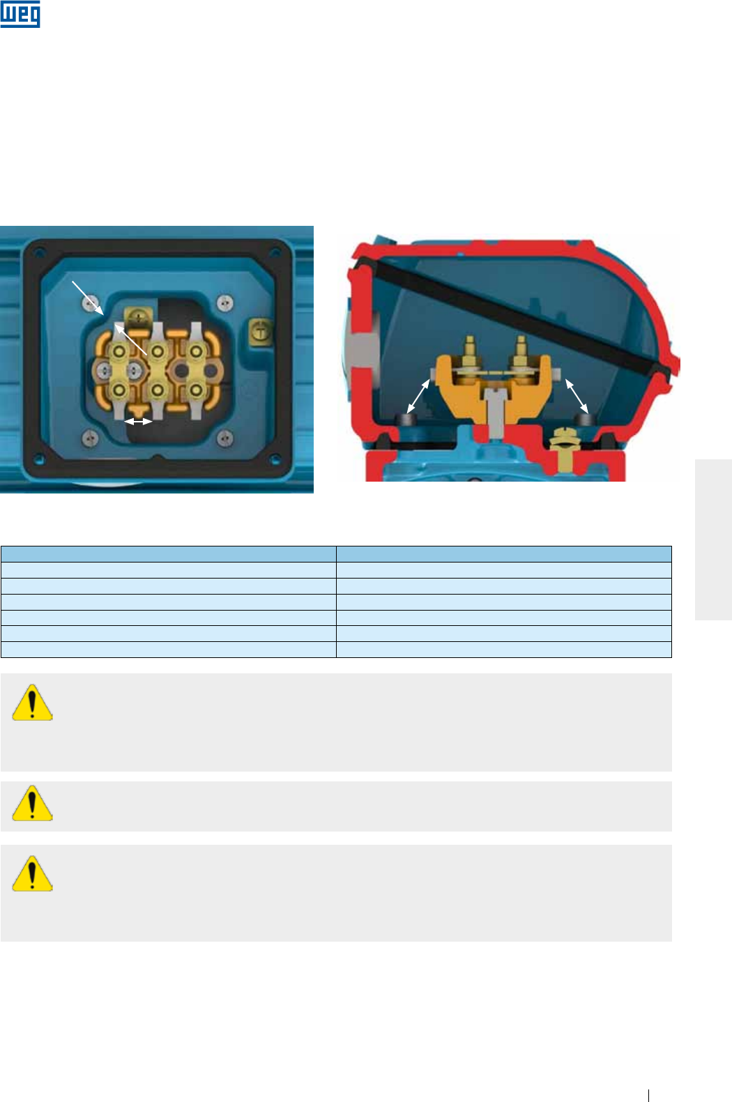
www.weg.net
Motores Elétricos 33
PORTUGUÊS
Assegurar que o motor esteja conectado corretamente à rede de alimentação elétrica através de contatos
seguros e permanentes.
Para motores sem placa de bornes, isolar os cabos terminais do motor, utilizando materiais isolantes
compatíveis com a tensão de alimentação e classe de isolamento informadas na placa de identificação.
Para a conexão do cabo de alimentação e do sistema de aterramento devem ser respeitados os torques de
aperto indicados na Tabela 8.7.
A distância de isolação (ver Figura 6.13) entre partes vivas não isoladas entre si e entre partes vivas e partes
aterradas deve respeitar a os valores indicados na Tabela 6.3.
Distância de isolação
Distância de isolação
Distância de isolação Distância de isolação
Figura 6.13 - Representação da distância de isolação.
Tabela 6.3 - Distância mínima de isolação (mm) x tensão de alimentação.
Tensão Distância mínima de isolação (mm)
U ≤ 440 V 4
440 < U ≤ 690 V 5.5
690 < U ≤ 1000 V 8
1000 < U ≤ 6900 V 45
6900 < U ≤ 11000 V 70
11000 < U ≤ 16500 V 105
Mesmo com o motor desligado, pode existir energia elétrica no interior da caixa de ligação utilizada
para a alimentação das resistências de aquecimento ou inclusive para energizar o enrolamento,
quando este estiver sendo utilizado como elemento de aquecimento.
Os capacitores de motores podem reter energia elétrica, mesmo com o motor desligado. Não toque os
capacitores e/ou os terminais do motor sem antes verificar a existência de tensão nos mesmos.
Após fazer a conexão do motor, certifique-se que nenhum corpo estranho permaneceu no interior
da caixa de ligação.
As entradas da(s) caixa(s) de ligação devem ser fechadas/protegidas para assim garantir o grau de
proteção do invólucro indicado na placa de identificação do motor.
As entradas de cabos utilizadas para alimentação e controle devem empregar componentes
(como, por exemplo, prensa-cabos e eletrodutos) que atendem as normas e regulamentações vigentes em
cada país.
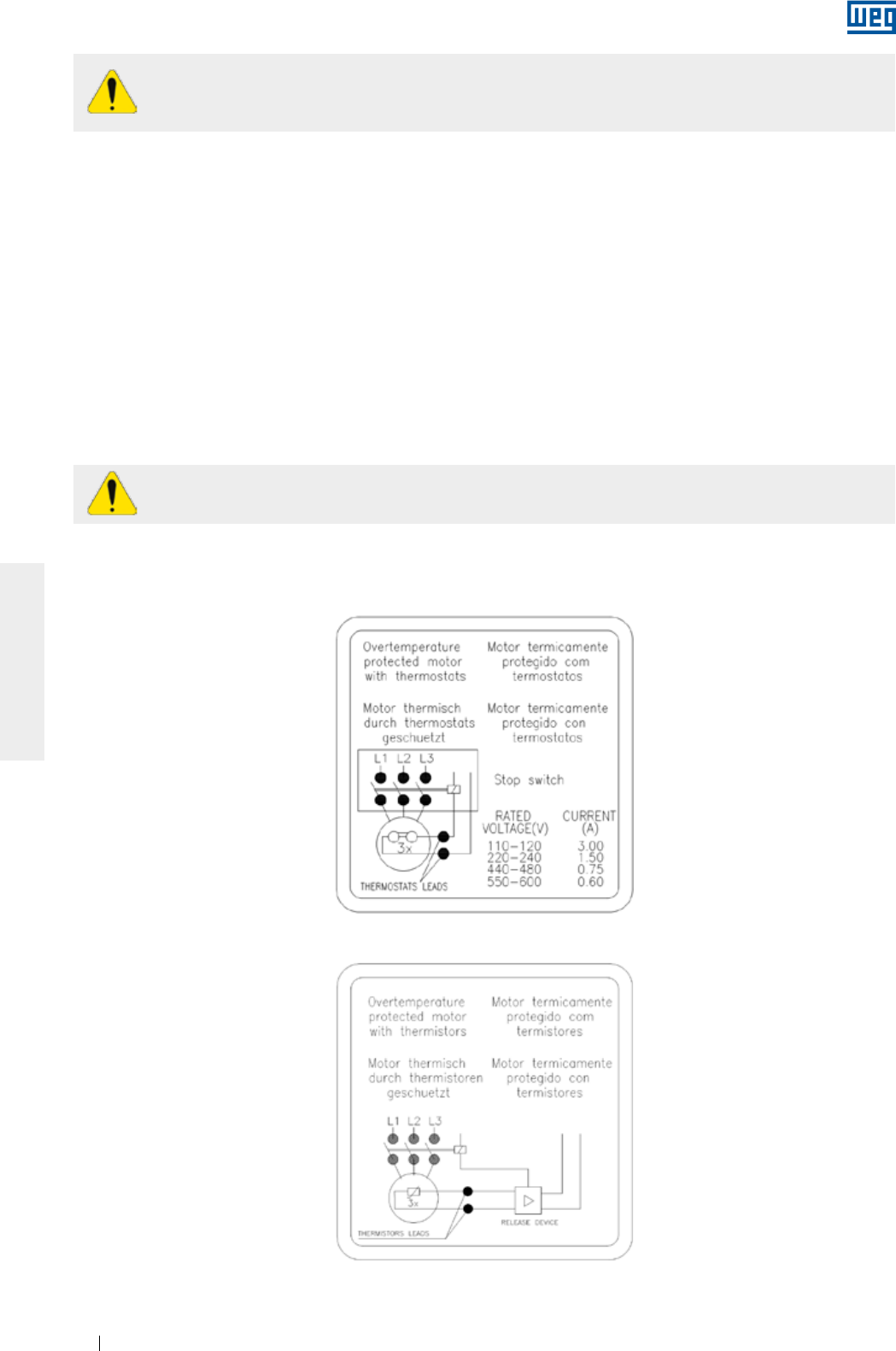
www.weg.net
Motores Elétricos34
PORTUGUÊS
Caso existam acessórios, como freio e ventilação forçada, estes devem ser conectados à rede de
alimentação, seguindo as informações de suas placas de identificação e os cuidados indicados
anteriormente.
Não aplicar tensão de teste superior a 2,5 V para termistores e corrente maior do que 1 mA para
RTDs (Pt-100) de acordo com a norma IEC 60751.
Todas as proteções, inclusive as contra sobrecorrente, devem ser ajustadas com base nas condições
nominais da máquina. Esta proteção também terá que proteger o motor em caso de curto-circuito, falta de
fase, ou rotor bloqueado.
Os ajustes dos dispositivos de segurança dos motores devem ser feitos segundo as normas vigentes.
Verificar o sentido de rotação do motor. Caso não haja nenhuma limitação devido à utilização de ventiladores
unidirecionais, é possível mudar o sentido de giro de motores trifásicos, invertendo duas fases de alimentação.
Para motores monofásicos, verificar o esquema de ligação na placa de identificação.
6.10. CONEXÃO DOS DISPOSITIVOS DE PROTEÇÃO TÉRMICA
Quando fornecido com dispositivos de proteção ou de monitoramento de temperatura, como: protetor térmico
bimetálico (termostatos), termistores, protetores térmicos do tipo Automático, Pt-100 (RTD), etc., seus terminais
devem ser conectados aos dispositivos de controle correspondentes, de acordo com as placas de
identificação dos acessórios. A não observação desse procedimento pode resultar em cancelamento da
garantia e risco para a instalação.
O esquema de ligação dos protetores térmicos bimetálicos (termostatos) e termistores é mostrado nas Figura
6.14 e Figura 6.15, respectivamente.
Figura 6.14 - Conexão dos protetores térmicos bimetálicos (termostatos)
Figura 6.15 - Conexão dos termistores
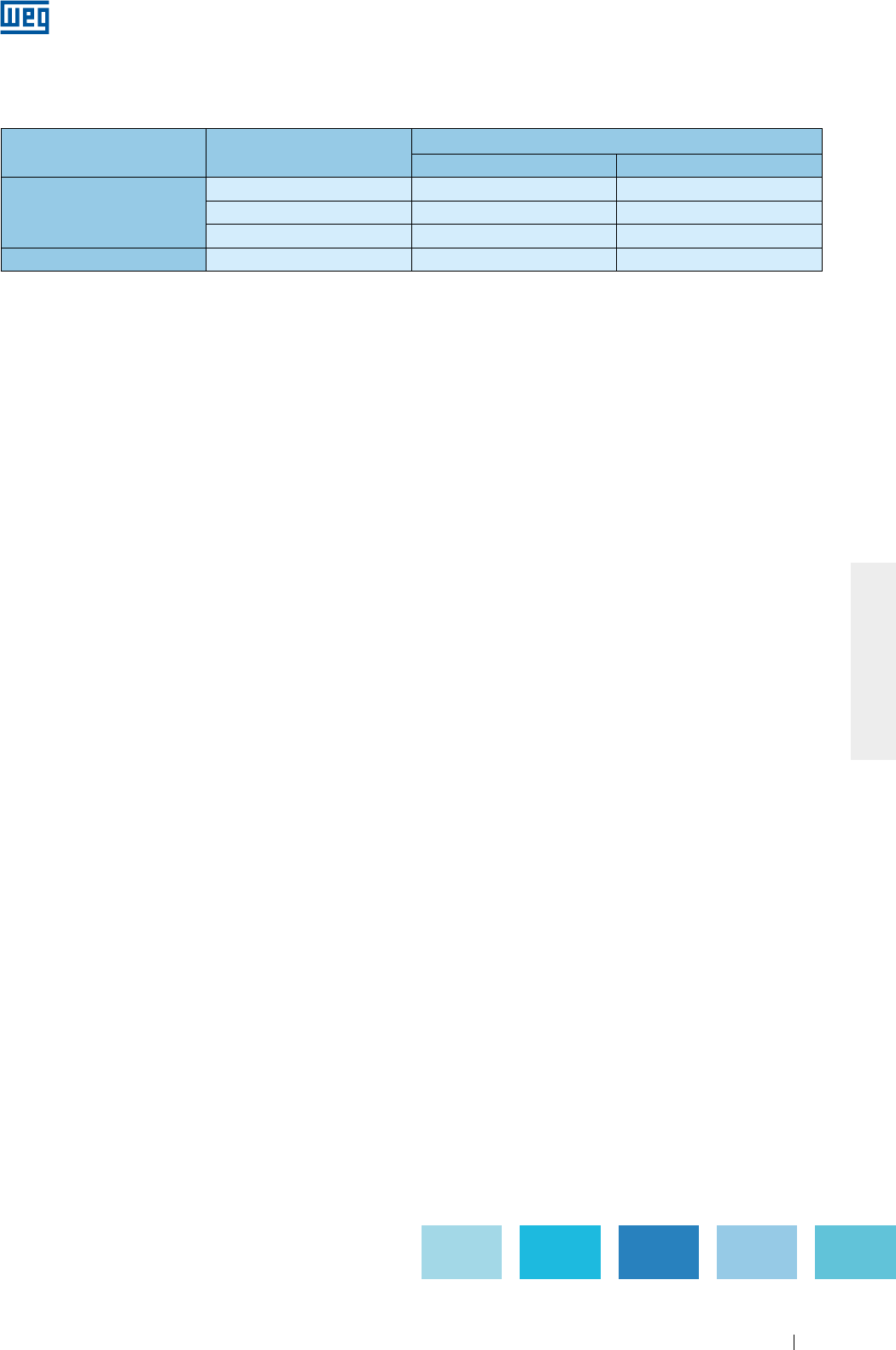
www.weg.net
Motores Elétricos 35
PORTUGUÊS
Os limites de temperatura de alarme e desligamento das proteções térmicas podem ser definidos de acordo
com a aplicação, porém não devem ultrapassar os valores indicados na Tabela 6.4.
Componente Classe de isolamento Temperatura máxima de operação (°C)
Alarme Desligamento
Enrolamento
B - 130
F 130 155
H 155 180
Mancal Todas 110 120
Tabela 6.4 - Temperatura máxima de atuação das proteções térmicas
Notas:
1) A quantidade e o tipo de proteção térmica instalados no motor são informados nas placas de identificação dos acessórios do mesmo.
2) No caso de proteção térmica com resistência calibrada (por exemplo, Pt-100), o sistema de proteção deve ser ajustado nas
temperaturas de operação indicada na Tabela 6.4.
6.11. TERMORRESISTORES (PT-100)
São elementos, cuja operação está baseada na característica de variação da resistência com a temperatura,
intrínseca em alguns materiais (geralmente platina, níquel ou cobre).
Possuem resistência calibrada, que varia linearmente com a temperatura, possibilitando um acompanhamento
contínuo do processo de aquecimento do motor pelo
display
do controlador, com alto grau de precisão e
sensibilidade de resposta. Sua aplicação é ampla nos diversos setores de técnicas de medição e
automatização de temperatura das indústrias. Geralmente, aplica-se em instalações de grande
responsabilidade, como por exemplo, em regime intermitente muito irregular. O mesmo detector pode servir
tanto para alarme como para desligamento.
A equivalência entre a resistência do Pt-100 e temperatura é apresentada na Tabela 6.5 e Figura 6.16.
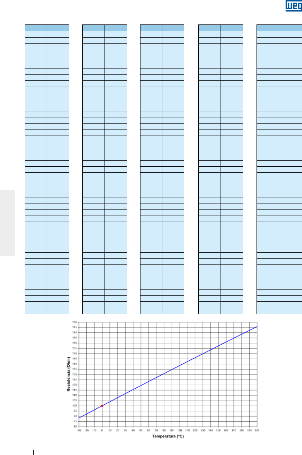
www.weg.net
Motores Elétricos36
PORTUGUÊS
ºC ºC ºC ºC ºC
-29 88.617 17 106.627 63 124.390 109 141.908 155 159.180
-28 89.011 18 107.016 64 124.774 110 142.286 156 159.553
-27 89.405 19 107.404 65 125.157 111 142.664 157 159.926
-26 89.799 20 107.793 66 125.540 112 143.042 158 160.298
-25 90.193 21 108.181 67 125.923 113 143.420 159 160.671
-24 90.587 22 108.570 68 126.306 114 143.797 160 161.043
-23 90.980 23 108.958 69 126.689 115 144.175 161 161.415
-22 91.374 24 109.346 70 127.072 116 144.552 162 161.787
-21 91.767 25 109.734 71 127.454 117 144.930 163 162.159
-20 92.160 26 110.122 72 127.837 118 145.307 164 162.531
-19 92.553 27 110.509 73 128.219 119 145.684 165 162.903
-18 92.946 28 110.897 74 128.602 120 146.061 166 163.274
-17 93.339 29 111.284 75 128.984 121 146.438 167 163.646
-16 93.732 30 111.672 76 129.366 122 146.814 168 164.017
-15 94.125 31 112.059 77 129.748 123 147.191 169 164.388
-14 94.517 32 112.446 78 130.130 124 147.567 170 164.760
-13 94.910 33 112.833 79 130.511 125 147.944 171 165.131
-12 95.302 34 113.220 80 130.893 126 148.320 172 165.501
-11 95.694 35 113.607 81 131.274 127 148.696 173 165.872
-10 96.086 36 113.994 82 131.656 128 149.072 174 166.243
-9 96.478 37 114.380 83 132.037 129 149.448 175 166.613
-8 96.870 38 114.767 84 132.418 130 149.824 176 166.984
-7 97.262 39 115.153 85 132.799 131 150.199 177 167.354
-6 97.653 40 115.539 86 133.180 132 150.575 178 167.724
-5 98.045 41 115.925 87 133.561 133 150.950 179 168.095
-4 98.436 42 116.311 88 133.941 134 151.326 180 168.465
-3 98.827 43 116.697 89 134.322 135 151.701 181 168.834
-2 99.218 44 117.083 90 134.702 136 152.076 182 169.204
-1 99.609 45 117.469 91 135.083 137 152.451 183 169.574
0 100.000 46 117.854 92 135.463 138 152.826 184 169.943
1 100.391 47 118.240 93 135.843 139 153.200 185 170.313
2 100.781 48 118.625 94 136.223 140 153.575 186 170.682
3 101.172 49 119.010 95 136.603 141 153.950 187 171.051
4 101.562 50 119.395 96 136.982 142 154.324 188 171.420
5 101.953 51 119.780 97 137.362 143 154.698 189 171.789
6 102.343 52 120.165 98 137.741 144 155.072 190 172.158
7 102.733 53 120.550 99 138.121 145 155.446 191 172.527
8 103.123 54 120.934 100 138.500 146 155.820 192 172.895
9 103.513 55 121.319 101 138.879 147 156.194 193 173.264
10 103.902 56 121.703 102 139.258 148 156.568 194 173.632
11 104.292 57 122.087 103 139.637 149 156.941 195 174.000
12 104.681 58 122.471 104 140.016 150 157.315 196 174.368
13 105.071 59 122.855 105 140.395 151 157.688 197 174.736
14 105.460 60 123.239 106 140.773 152 158.061 198 175.104
15 105.849 61 123.623 107 141.152 153 158.435 199 175.472
16 106.238 62 124.007 108 141.530 154 158.808 200 175.840
Tabela 6.5 - Equivalência entre a resistência do Pt-100 e temperatura
Figura 6.16 - Resistência ôhmica do Pt-100 x temperatura
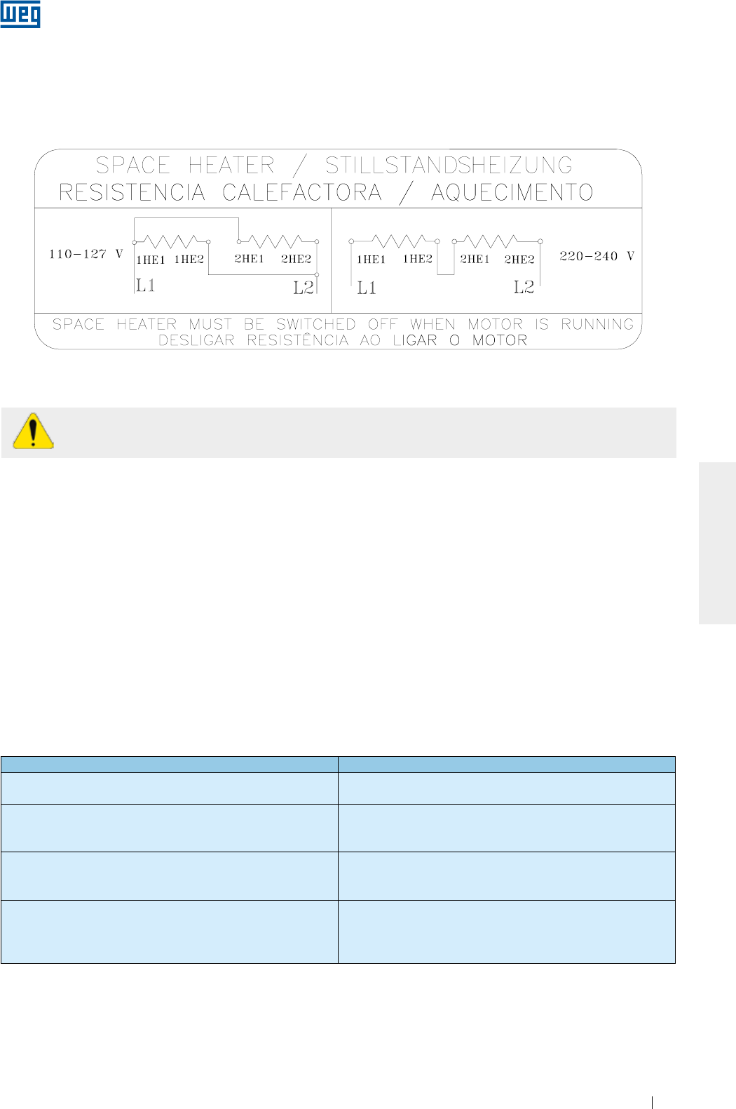
www.weg.net
Motores Elétricos 37
PORTUGUÊS
6.13. MÉTODOS DE PARTIDA
Sempre que possível, a partida do motor deve ser direta (em plena tensão). É o método mais simples, no
entanto, somente é viável quando a corrente de partida não afeta a rede de alimentação. É importante seguir
as regras vigentes da concessionária de energia elétrica.
Nos casos em que a corrente de partida do motor é alta, podem ocorrer as seguintes consequências:
a) Elevada queda de tensão no sistema de alimentação da rede, provocando interferência nos equipamentos
instalados neste sistema;
b)
O superdimensionamento do sistema de proteção (cabos, contatores), o que eleva os custos da instalação.
Caso a partida direta não seja possível devido aos problemas citados acima, pode-se usar o método de partida indireta
compatível com a carga e a tensão do motor, para reduzir a corrente de partida.
Quando é utilizado um método de partida com tensão reduzida, o torque de partida do motor também será reduzido.
A Tabela 6.6 indica os métodos de partida indireta possíveis de serem utilizados de acordo com a quantidade
de cabos do motor.
Quantidade de cabos Métodos de partidas possíveis
3 cabos Chave Compensadora
Soft-starter
6 cabos
Chave Estrela - Triângulo
Chave Compensadora
Soft-starter
9 cabos
Chave Série - Paralela
Chave Compensadora
Soft-starter
12 cabos
Chave Estrela - Triângulo
Chave Série - Paralela
Chave Compensadora
Soft-starter
Tabela 6.6 - Métodos de partida x quantidade de cabos
6.12. CONEXÃO DA RESISTÊNCIA DE AQUECIMENTO
Antes de ligar a resistência de aquecimento, deve ser observado o esquema de ligação da resistência de
aquecimento disponível na placa de identificação adicional. Para motores fornecidos com resistência de
aquecimento que permite a sua ligação em duas tensões, ver Figura 6.17.
Figura 6.17 - Esquema de ligação da resistência de aquecimento para tensão 110-127/220-240 V.
As resistências de aquecimento nunca devem estar energizadas enquanto o motor estiver
operando.
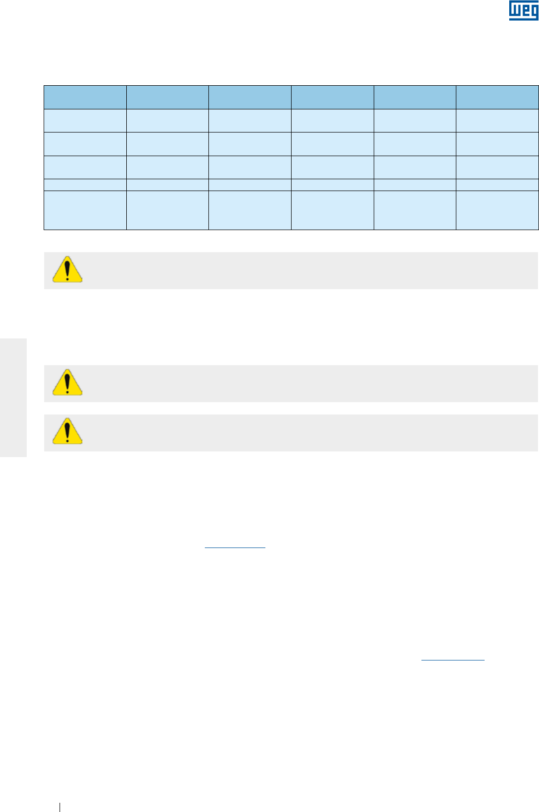
www.weg.net
Motores Elétricos38
PORTUGUÊS
A Tabela 6.7 indica exemplos de métodos de partida indireta possíveis de serem utilizados, de acordo com a
tensão indicada na placa de identificação do motor e a tensão da rede elétrica.
Tabela 6.7 - Métodos de partida x tensão
Tensão da placa
de identificação
Tensão da rede
elétrica
Partida com chave
Estrela - Triângulo
Partida com chave
Compensadora
Partida com chave
Série - Paralela
Partida com
Soft-Starter
220/380 V 220 V
380 V
SIM
NÃO
SIM
SIM
NÃO
NÃO
SIM
SIM
220/440 V 220 V
440 V
NÃO
NÃO
SIM
SIM
SIM
NÃO
SIM
SIM
230/460 V 230 V
460 V
NÃO
NÃO
SIM
SIM
SIM
NÃO
SIM
SIM
380/660 V 380 V SIM SIM NÃO SIM
220/380/440 V
220 V
380 V
440 V
SIM
NÃO
SIM
SIM
SIM
SIM
SIM
SIM
NÃO
SIM
SIM
SIM
Os motores WQuattro devem ser acionados diretamente a partir da rede ou ser acionados por
inversor de frequência em modo escalar.
Outro método de partida possível que não sobrecarregue a rede de alimentação é a utilização de um inversor
de frequência. Para mais informações sobre motores alimentados com inversor de frequência ver item 6.14.
6.14. MOTORES ALIMENTADOS POR INVERSOR DE FREQUÊNCIA
A operação com inversor de frequência deve ser informada no momento da compra devido a
possíveis diferenças construtivas necessárias para esse tipo de acionamento.
Motores Wmagnet devem ser acionados somente por inversor de frequência WEG.
O conversor utilizado para acionar motores com tensão de alimentação até 690 V deve possuir modulação
PWM com controle vetorial.
Quando um motor opera com inversor de frequência abaixo da frequência nominal, é necessário reduzir o
torque fornecido pelo motor a fim de evitar sobreaquecimento. Os valores de redução de torque (derating
torque) podem ser encontrados no item 6.4 do "Guia Técnico Motores de Indução Alimentados por Inversores
de Frequência PWM" disponível em www.weg.net.
Para operação acima da frequência nominal deve ser observado:
g Operação com potência constante;
g O motor pode fornecer no máximo 95% da potência nominal;
g Respeitar a rotação máxima, considerando os seguintes critérios:
g Máxima frequência de operação informada na placa adicional;
g Limite de rotação mecânica do motor.
Recomendações para os cabos de conexão entre motor e inversor são indicadas no item 6.8 do "Guia Técnico
Motores de Indução Alimentados por Inversores de Frequência PWM" disponível em www.weg.net.
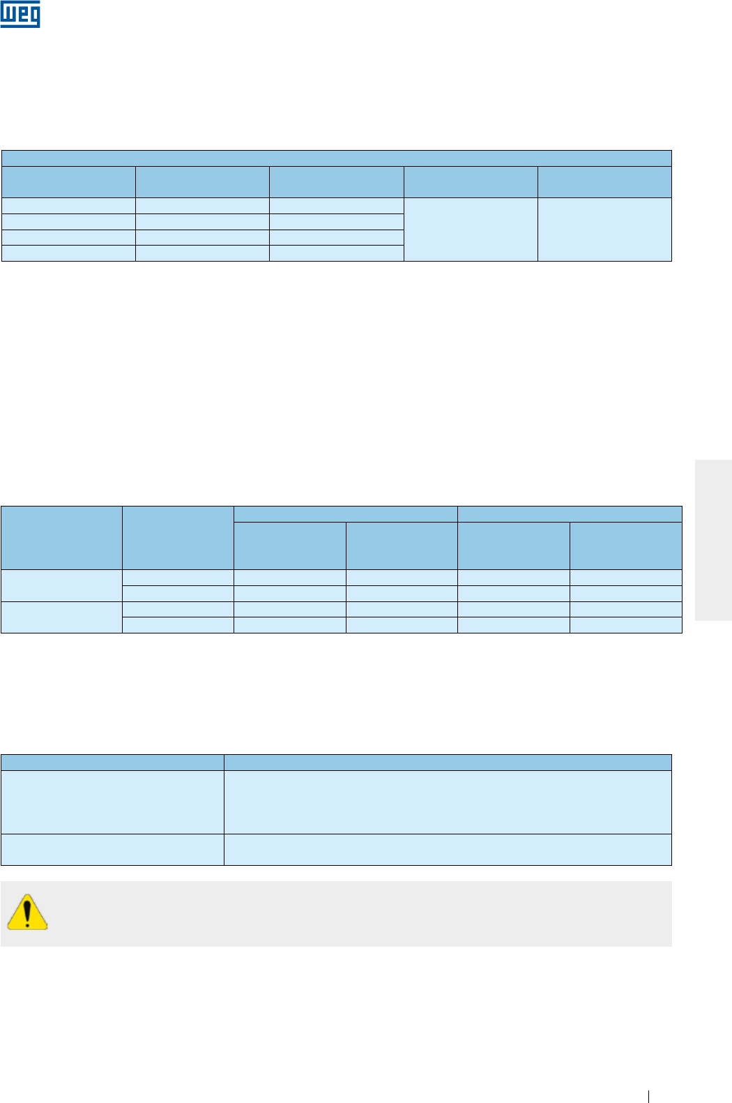
www.weg.net
Motores Elétricos 39
PORTUGUÊS
Para motores fornecidos com sistema de aterramento do eixo, deve ser observado constantemente
o estado de conservação da escova e, ao chegar ao fim de sua vida útil, a mesma deve ser
substituída por outra de mesma especificação.
Tabela 6.8 - Critérios para utilização de motores com bobina pré-formada alimentados com inversor de frequência
Tensão de operação
do motor
Tipo de
modulação
Isolação da espira (fase-fase) Isolação principal (fase-terra)
Tensão de pico
nos terminais do
motor
dV/dt nos
terminais do motor
Tensão de pico
nos terminais do
motor
dV/dt nos
terminais do motor
690 < Vnom ≤ 4160 V Senoidal ≤ 5900 V ≤ 500 V/µs ≤ 3400 V ≤ 500 V/µs
PWM ≤ 9300 V ≤ 2700 V/µs ≤ 5400 V ≤ 2700 V/µs
4160 < Vnom ≤ 6600 V Senoidal ≤ 9300 V ≤ 500 V/µs ≤ 5400 V ≤ 500 V/µs
PWM ≤ 14000 V ≤ 1500 V/µs ≤ 8000 V ≤ 1500 V/µs
6.14.2. Isolamento dos mancais
Como padrão, apenas motores na carcaça IEC 400 (NEMA 68) e acima são fornecidos com mancal isolado.
Recomenda-se isolar os mancais para operação com inversor de frequência de acordo com a Tabela 6.9.
Tabela 6.9 - Recomendação sobre o isolamento dos mancais para motores acionados por inversor de frequência
Carcaça Recomendação
IEC 315 e 355
NEMA 445/7, 447/9, L447/9, 504/5,
5006/7/8, 5009/10/11, 586/7, 5807/8/9,
5810/11/12 e 588/9
Um mancal isolado
Aterramento entre eixo e carcaça por meio de escova
IEC 400 e acima
NEMA 6800 e acima
Mancal traseiro isolado
Aterramento entre eixo e carcaça por meio de escova
6.14.1. Uso de filtros (dV/dt)
6.14.1.1. Motor com fio circular esmaltado
Motores com tensão nominal de até 690 V, quando alimentados por inversores de frequência, não requerem
filtros, se observados os critérios a seguir:
Critérios para utilização de motores de fio circular esmaltado alimentados por inversor de frequência 1
Tensão de operação
do motor2
Tensão de pico no
motor (max)
dV/dt na saída do
conversor (max)
Rise Time3 do
conversor (mín)
MTBP3 Tempo entre
pulsos (min)
Vnom ≤ 460 V ≤ 1600 V ≤ 5200 V/µs
≥ 0,1 µs ≥ 6 µs
460 < Vnom ≤ 575 V ≤ 1800 V ≤ 6500 V/µs
575 < Vnom ≤ 690 V4≤ 1600 V ≤ 5200 V/µs
575 < Vnom ≤ 690 V5≤ 2200 V ≤ 7800 V/µs
1. Para motores com fio circular esmaltado com tensão 690 < Vnom ≤ 1100 V, consultar a WEG.
2. Para motores com dupla tensão, exemplo 380/660 V, devem ser observados os critérios da tensão menor
(380 V).
3. Informações fornecidas pelo fabricante do inversor.
4. Quando não informado no momento da compra que o motor irá operar com inversor de frequência.
5. Quando informado no momento da compra que o motor irá operar com inversor de frequência.
6.14.1.2. Motor com bobina pré-formada
Motores com bobina pré-formada (média e alta tensão, independente do tamanho da carcaça e baixa tensão a
partir da carcaça IEC 500 / NEMA 80) específicos para utilização com inversor de frequência não requerem
filtros, se observados os critérios da Tabela 6.8.
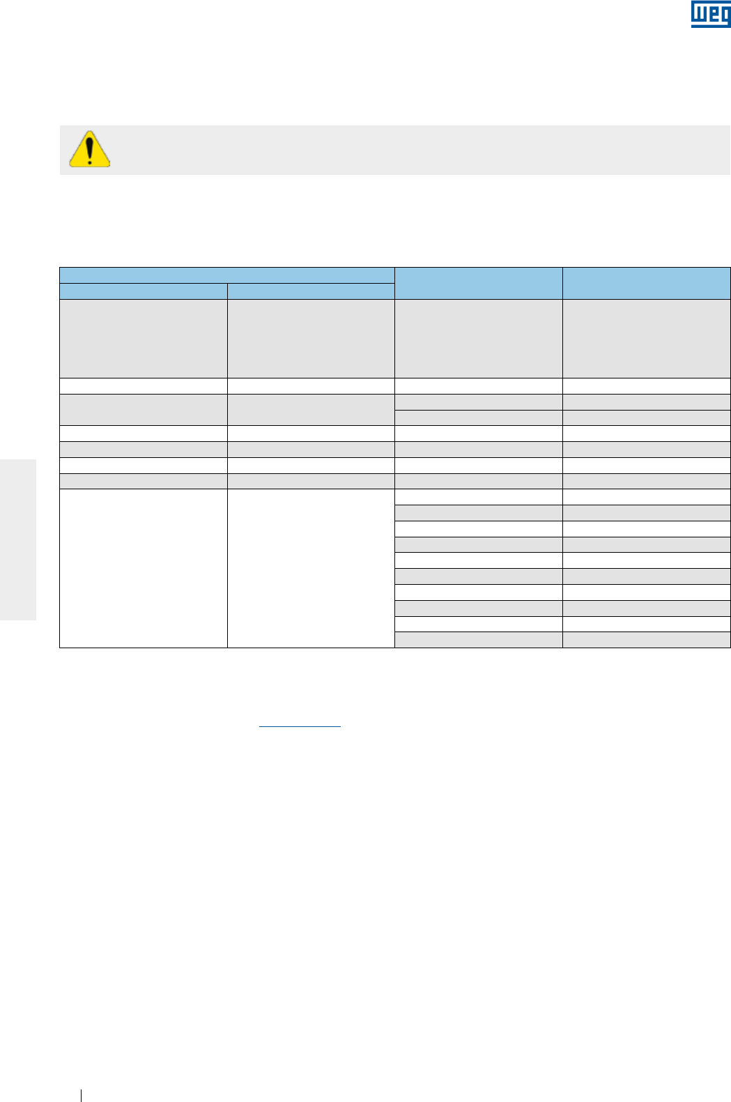
www.weg.net
Motores Elétricos40
PORTUGUÊS
A não observação dos critérios e recomendações expostos neste manual pode resultar na
anulação da garantia do produto.
6.14.3. Frequência de chaveamento
A frequência mínima de chaveamento do inversor deverá ser de 2,5 kHz.
Recomenda-se que a frequência máxima de chaveamento do conversor seja de 5 kHz.
6.14.4. Limite da rotação mecânica
A Tabela 6.10 mostra as rotações máximas permitidas para motores acionados por inversor de frequência.
Tabela 6.10 - Rotação máxima do motor (em RPM)
Carcaça Rolamento dianteiro Rotação máxima
para motor padrão
IEC NEMA
63-90 143/5
6201
6202
6203
6204
6205
10400
100 - 6206 8800
112 182/4 6207 7600
6307 6800
132 213/5 6308 6000
160 254/6 6309 5300
180 284/6 6311 4400
200 324/6 6312 4200
225-630 364/5-9610
6314 3600
6315 3600
6316 3200
6319 3000
6220 3600
6320 2200
6322 1900
6324 1800
6328 1800
6330 1800
Nota: para selecionar a rotação máxima permitida para o motor, considere a curva de redução de torque do motor.
Para mais informações sobre o uso de inversor de frequência, ou como dimensioná-lo corretamente para a
sua aplicação, favor contatar a WEG ou o "Guia Técnico Motores de Indução Alimentados por Inversores de
Frequência PWM" disponível em www.weg.net.
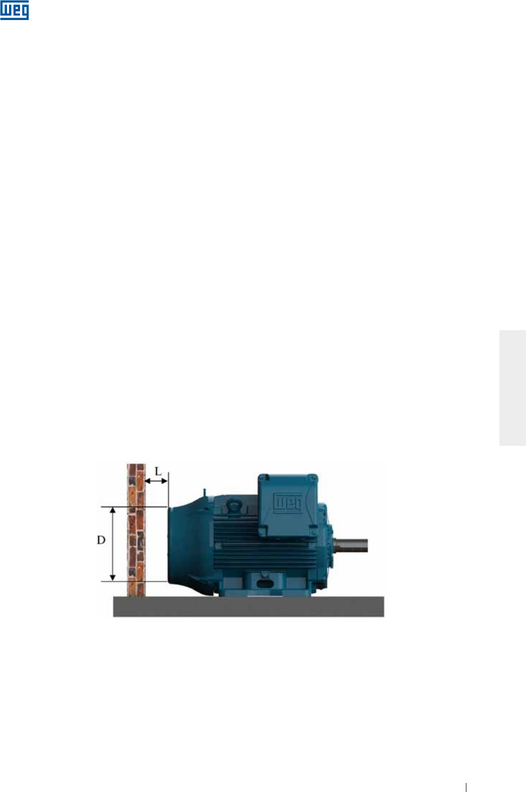
www.weg.net
Motores Elétricos 41
PORTUGUÊS
7. OPERAÇÃO
7.1. PARTIDA DO MOTOR
Após executar os procedimentos de instalação, alguns aspectos devem ser verificados antes da partida inicial
do motor, principalmente se o motor não foi colocado imediatamente em operação após sua instalação. Aqui
devem ser verificados os seguintes itens:
g Se os dados que constam na placa de identificação (tensão, corrente, esquema de ligação, grau de
proteção, refrigeração, fator de serviço, entre outras) estão de acordo com a aplicação;
g A correta montagem e alinhamento do conjunto (motor + máquina acionada);
g O sistema de acionamento do motor, considerando que a rotação do motor não ultrapasse a velocidade
máxima estabelecida na Tabela 6.10;
g A resistência de isolamento do motor, conforme item 5.4;
g O sentido de rotação do motor;
g A integridade da caixa de ligação, que deve estar limpa e seca, seus elementos de contato isentos de
oxidação, suas vedações em condições apropriadas de uso e suas entradas de cabos corretamente
fechadas/protegidas de acordo com o grau de proteção;
g As conexões do motor, verificando se foram corretamente realizadas, inclusive aterramento e cabos
auxiliares, conforme recomendações do item 6.9;
g O correto funcionamento dos acessórios (freio, encoder, proteção térmica, ventilação forçada, etc.)
instalados no motor;
g A condição dos rolamentos. Se apresentarem sinais de oxidação, devem ser substituídos. Caso não
apresentem oxidação, realize o procedimento de relubrificação conforme descrito no item 8.2. Motores
instalados há mais de dois anos, mas que não entraram em operação devem ter seus rolamentos
substituídos antes de serem colocados em operação;
g Nos motores com mancais de deslizamento deve ser assegurado:
g O nível correto de óleo do mancal. O mesmo deve estar na metade do visor (ver Figura 6.8);
g Que o motor não parte e nem opere com cargas radiais ou axiais;
g Que quando o motor for armazenado por período igual ou maior ao intervalo de troca de óleo, o óleo
deverá ser trocado antes da colocação em funcionamento;
g A análise da condição dos capacitores, se existirem. Para motores instalados por um período superior a dois
anos, mas que não entraram em operação, recomenda-se a substituição de seus capacitores de partida de
motores monofásicos;
g Que entradas e saídas de ar estejam completamente desobstruídas. O mínimo espaço livre até a parede
mais próxima (L) deve ser ¼ do diâmetro da entrada de ar da defletora (D), conforme Figura 7.1. O ar na
entrada do motor deve estar na temperatura ambiente.
Figura 7.1 - Distancia mínima do motor até a parede
Como referência, podem ser seguidas as distâncias mínimas apresentadas na Tabela 7.1;
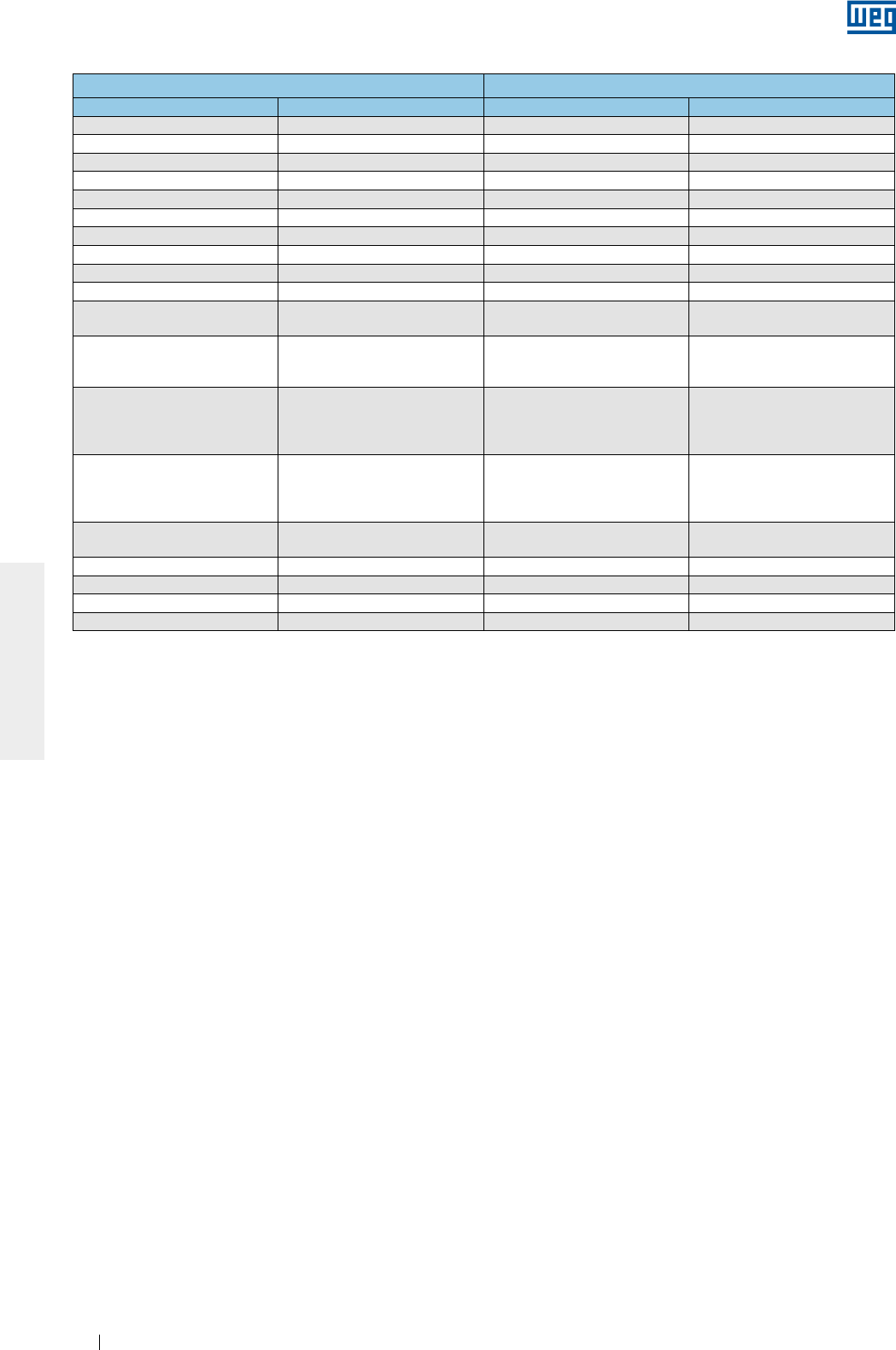
www.weg.net
Motores Elétricos42
PORTUGUÊS
Tabela 7.1 - Distância mínima entre a tampa defletora e a parede
Carcaça Distância entre a tampa defletora e a parede (L)
IEC NEMA mm Inches
63 - 25 0,96
71 - 26 1,02
80 - 30 1,18
90 143/5 33 1,30
100 - 36 1,43
112 182/4 41 1,61
132 213/5 50 1,98
160 254/6 65 2,56
180 284/6 68 2,66
200 324/6 78 3,08
225
250
364/5
404/5 85 3,35
280
444/5
445/7
447/9
108 4,23
315
L447/9
504/5
5006/7/8
5009/10/11
122 4,80
355
586/7
588/9
5807/8/9
5810/11/12
136 5,35
400 6806/7/8
6809/10/11 147 5,79
450 7006/10 159 6,26
500 8006/10 171 6,73
560 8806/10 185 7,28
630 9606/10 200 7,87
g Que as vazões e temperaturas da água estejam corretas, quando uitlizadas na refrigeração do motor. Ver item 7.2.
g Que todas as partes girantes, como polias, acoplamentos, ventiladores externos, eixo, etc., estejam
protegidas contra toques acidentais.
Outros testes e verificações que não constam nesta relação podem se fazer necessários, em função das
características específicas da instalação, aplicação e/ou do motor.
Após todas as verificações terem sido realizadas, seguir o procedimento a seguir para efetuar a partida do
motor:
g Ligar a máquina sem nenhuma carga (quando possível), acionando a chave de partida como se fosse um
pulso, verificando o sentido de rotação, a presença de ruído, vibração ou outra condição anormal de
operação;
g Religar o motor, que deve partir e funcionar de maneira suave. Caso isso não ocorra, desligue o motor,
verifique novamente o sistema de montagem e conexões antes de uma nova partida.
g No caso de vibrações excessivas, verificar se os parafusos de fixação estão adequadamente apertados ou
se a vibração é proveniente de máquinas adjacentes. Verificar periodicamente a vibração, respeitando os
limites apresentados no item 7.2.1;
g Operar o motor sob carga nominal por um pequeno período de tempo e comparar a corrente de operação
com a corrente indicada na placa de identificação;
g Recomenda-se ainda que algumas variáveis do motor sejam acompanhadas até seu equilíbrio térmico:
corrente, tensão, temperatura nos mancais e na superfície externa da carcaça, vibração e ruído;
g Recomenda-se que os valores de corrente e tensão sejam registrados no relatório de instalação.
Devido ao valor elevado da corrente de partida dos motores de indução, o tempo gasto na aceleração nas
cargas de inércia apreciável resulta na elevação rápida da temperatura do motor. Se o intervalo entre partidas
sucessivas for muito reduzido, isso resultará no aumento da temperatura nos enrolamentos, danificando-os ou
reduzindo a sua vida útil. Caso não seja especificado regime de serviço diferente de S1 / CONT. na placa de
identificação do motor, os motores estão aptos para:
g Duas partidas sucessivas, sendo a primeira feita com o motor frio, isto é, com seus enrolamentos na
temperatura ambiente e uma segunda partida logo a seguir, porém após o motor ter desacelerado até atingir
seu repouso;
g Uma partida com o motor a quente, ou seja, com os enrolamentos na temperatura de regime.
O item 10 lista alguns problemas de mau funcionamento do motor, com suas possíveis causas.
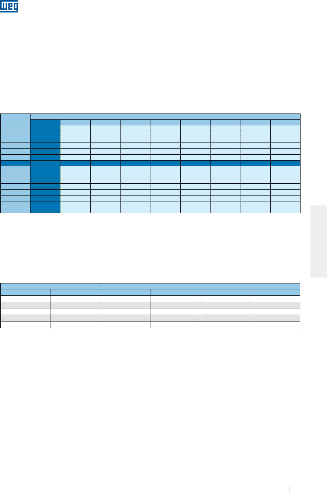
www.weg.net
Motores Elétricos 43
PORTUGUÊS
7.2. CONDIÇÕES DE OPERAÇÃO
Caso nenhuma outra condição seja informada no momento da compra, os motores elétricos são projetados
para operar a uma altitude limitada a 1000 m acima do nível do mar e em temperatura ambiente entre -20 °C e
+40 °C. Qualquer variação das condições do ambiente, onde o motor irá operar, deve estar indicada na placa
de identificação do motor.
Alguns componentes precisam ser trocados quando a temperatura ambiente é diferente da indicada acima.
Favor contatar a WEG para verificar as características especiais.
Para temperaturas e altitudes diferentes das indicadas acima, deve-se utilizar a Tabela 7.2 para encontrar o
fator de correção que deverá ser utilizado para definir a potência útil disponível (Pmax = Pnom x Fator de
correção).
O ambiente no local de instalação deverá ter condições de renovação de ar da ordem de 1m³ por segundo
para cada 100 kW ou fração de potência do motor. Para motores ventilados, que não possuem ventilador
próprio, a ventilação adequada do motor é de responsabilidade do fabricante do equipamento. Caso não haja
especificação da velocidade de ar mínima entre as aletas do motor em uma placa de identificação, devem ser
seguidos os valores indicados na Tabela 7.3. Os valores apresentados na Tabela 7.3 são válidos para motores
aletados alimentados na frequência de 60 Hz. Para obtenção das velocidades mínimas de ar em 50 Hz deve-se
multiplicar os valores da tabela por 0,83.
Tabela 7.2 - Fatores de correção considerando a altitude e a temperatura ambiente
Tabela 7.3 - Velocidade mínima de ar entre as aletas do motor (m/s)
Carcaça Polos
IEC NEMA 2 4 6 8
63 a 90 143/5 14 7 5 4
100 a 132 182/4 and 213/5 18 10 8 6
160 a 200 364/5 to 444/5 20 20 12 7
225 a 280 364/5 to 444/5 22 22 18 12
315 a 355 445/7 to 588/9 25 25 20 15
As variações da tensão e frequência de alimentação podem afetar as características de desempenho e a
compatibilidade eletromagnética do motor. Estas variações de alimentação devem seguir os valores
estabelecidos nas normas vigentes. Exemplos:
g ABNT NBR 17094 - Partes 1 e 2. O motor está apto a fornecer torque nominal, sob as seguintes zonas de
variação de tensão e frequência:
g Zona A: ±5% de tensão e ±2% de frequência;
g Zona B: ±10% de tensão e +3% -5% de frequência.
Quando operado na Zona A ou B, o motor pode apresentar variações de desempenho e atingir temperaturas
mais elevadas. Estas variações são maiores para a operação na zona B. Não é recomendada uma operação
prolongada do motor na zona B.
g IEC 60034-1. O motor está apto a fornecer torque nominal, sob as seguintes zonas de variação de tensão e
frequência:
g Zona A: ±5% de tensão e ±2% de frequência;
g Zona B: ±10% de tensão e +3% -5% de frequência.
Quando operado na Zona A ou B, o motor pode apresentar variações de desempenho e atingir temperaturas
mais elevadas. Estas variações são maiores para a operação na zona B. Não é recomendada a operação
prolongada do motor na zona B. Para motores multitensão (exemplo 380-415/660 V) é permitida uma variação
de tensão de ±5%.
g NEMA MG 1 Parte 12. O motor está apto a operar em uma das seguintes variações:
g ±10% de tensão, com frequência nominal;
T (°C) Altitude (m)
1000 1500 2000 2500 3000 3500 4000 4500 5000
10 0,97 0,92 0,88
15 0,98 0,94 0,90 0,86
20 1,00 0,95 0,91 0,87 0,83
25 1,00 0,95 0,93 0,89 0,85 0,81
30 1,00 0,96 0,92 0,90 0,86 0,82 0,78
35 1,00 0,95 0,93 0,90 0,88 0,84 0,80 0,75
40 1,00 0,97 0,94 0,90 0,86 0,82 0,80 0,76 0,71
45 0,95 0,92 0,90 0,88 0,85 0,81 0,78 0,74 0,69
50 0,92 0,90 0,87 0,85 0,82 0,80 0,77 0,72 0,67
55 0,88 0,85 0,83 0,81 0,78 0,76 0,73 0,70 0,65
60 0,83 0,82 0,80 0,77 0,75 0,73 0,70 0,67 0,62
65 0,79 0,76 0,74 0,72 0,70 0,68 0,66 0,62 0,58
70 0,74 0,71 0,69 0,67 0,66 0,64 0,62 0,58 0,53
75 0,70 0,68 0,66 0,64 0,62 0,60 0,58 0,53 0,49
80 0,65 0,64 0,62 0,60 0,58 0,56 0,55 0,48 0,44
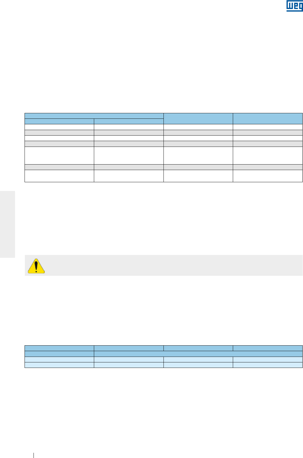
www.weg.net
Motores Elétricos44
PORTUGUÊS
g ±5 de frequência, com tensão nominal;
g Uma combinação de variação de tensão e frequência de ±10%, desde que a variação de frequência não
seja superior a ±5%.
Para motores que são resfriados através do ar ambiente, as entradas e saídas de ar devem ser limpas em
intervalos regulares para garantir uma livre circulação do ar, já que o ar quente não deve retornar para o motor.
O ar utilizado para refrigeração do motor deve estar na temperatura ambiente, limitada a faixa de temperatura
indicada na placa de identificação do motor (quando não indicado, considerar uma faixa de temperatura entre
-20 °C e +40 °C).
Para motores refrigerados à água, os valores da vazão da água para cada tamanho de carcaça, bem como a
máxima elevação de temperatura da água após circular pelo motor são mostrados na Tabela 7.4. A
temperatura da água na entrada não deve exceder 40 °C.
Tabela 7.4 - Vazão e máxima elevação de temperatura de água
Carcaça Vazão
(litros/minuto)
Máxima elevação de
temperatura de água (°C)
IEC NEMA
180 284/6 12 5
200 324/6 12 5
225 364/5 12 5
250 404/5 12 5
280
444/5
445/7
447/9
15 6
315 504/5 16 6
355 586/7
588/9 25 6
Para motores com lubrificação do tipo Oil Mist, em caso de falha do sistema de bombeamento de óleo, é
permitida uma operação em regime contínuo com o tempo máximo de uma hora de operação.
Considerando-se que o calor do sol causa aumento da temperatura de operação, motores instalados
externamente devem sempre estar protegidos contra a incidência direta dos raios solares.
Possíveis desvios em relação à operação normal (atuação de proteções térmicas, aumento do nível de ruído,
vibração, temperatura e corrente) devem ser examinados e eliminados por pessoal capacitado. Em caso de
dúvidas, desligar o motor imediatamente e contatar um Assistente Técnico Autorizado WEG.
A não observação dos critérios e recomendações expostos neste manual pode resultar na
anulação da garantia do produto.
7.2.1. Limites da severidade de vibração
A severidade de vibração é o máximo valor de vibração encontrada, dentre todos os pontos e direções
recomendados .
A Tabela 7.5 indica os valores admissíveis da severidade de vibração recomendados na norma IEC 60034-14
para as carcaças IEC 56 a 400, para os graus de vibração A e B.
Os limites de severidade da Tabela 7.5 são apresentados em termos do valor médio quadrático (= valor RMS
ou valor eficaz) da velocidade de vibração em mm/s medidos em condição de suspensão livre (base elástica).
Tabela 7.5 - Limites recomendados para a severidade de vibração de acordo com a norma IEC 60034-14.
Altura do eixo [mm] 56 ≤ H ≤ 132 132 < H ≤ 280 H > 280
Grau de vibração Severidade de vibração em base elástica [mm/s RMS]
A1,6 2,2 2,8
B0,7 1,1 1,8
Notas:
1 - Os valores da Tabela 7.5 são válidos para medições realizadas com a máquina desacoplada e sem carga, operando na frequência e
tensão nominais.
2 - Os valores da Tabela 7.5 são válidos independentemente do sentido de rotação da máquina.
3 - A Tabela 7.5 não se aplica para motores trifásicos com comutador, motores monofásicos, motores trifásicos com alimentação
monofásica ou para máquinas fixadas no local de instalação, acopladas em suas cargas de acionamento ou cargas acionadas.
Para motor padrão, de acordo com a norma NEMA MG 1, o limite de vibração é de 0.15 in/s (polegadas/
segundo pico), na mesma condição de suspensão livre e desacoplado.
Nota:
Para condição de operação em carga recomenda-se o uso da norma ISO 10816-3 para avaliação dos limites de vibração do motor. Na
condição em carga, a vibração do motor será influenciada por vários fatores, entre eles, tipo de carga acoplada, condição de fixação do
motor, condição de alinhamento com a carga, vibração da estrutura ou base devido a outros equipamentos, etc..
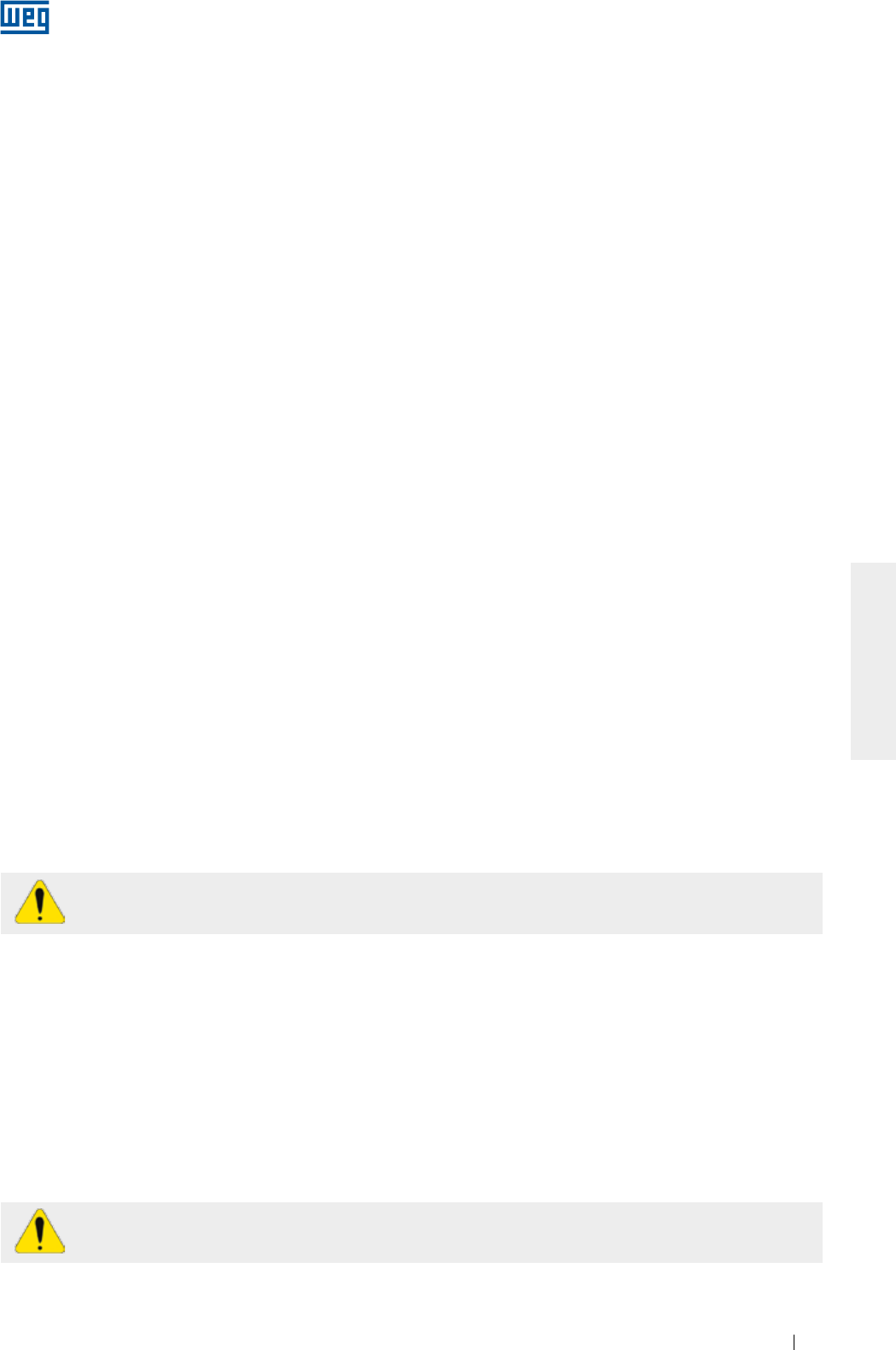
www.weg.net
Motores Elétricos 45
PORTUGUÊS
8. MANUTENÇÃO
A finalidade da manutenção é prolongar ao máximo possível a vida útil do equipamento. A não observância de
um dos itens relacionados a seguir pode levar a paradas não desejadas do equipamento.
Caso, durante a manutenção, houver necessidade de transporte dos motores com rolamentos de rolos ou
contato angular, devem ser utilizados os dispositivos de travamento do eixo fornecidos com o motor. Todos os
motores HGF, independente do tipo de mancal, devem ter seu eixo travado durante o transporte.
Qualquer serviço em máquinas elétricas deve ser realizado apenas por pessoal capacitado, utilizando somente
ferramentas e métodos adequados. Antes de iniciar qualquer serviço, as máquinas devem estar
completamente paradas e desconectadas da rede de alimentação, inclusive os acessórios (resistência de
aquecimento, freio, etc.).
Assistentes técnicos ou pessoal não capacitado e sem autorização para fazer manutenção e/ou reparar
motores são totalmente responsáveis pelo trabalho executado e pelos eventuais danos que possam ocorrer
durante o seu funcionamento.
8.1. INSPEÇÃO GERAL
A frequência com que devem ser realizadas as inspeções depende do tipo do motor, da aplicação e das
condições do local da instalação. Durante a inspeção, recomenda-se:
g
Fazer uma inspeção visual do motor e do acoplamento, observando os níveis de ruído, da vibração,
alinhamento, sinais de desgastes, oxidação e peças danificadas. Substituir as peças, quando for necessário;
gMedir a resistência de isolamento conforme descrito no item 5.4;
g
Manter a carcaça limpa, eliminando todo acúmulo de óleo ou de pó na parte externa do motor para assim
facilitar a troca de calor com o meio ambiente;
gVerificar a condição do ventilador e das entradas e saídas de ar, assegurando um livre fluxo do ar;
gVerificar o estado das vedações e efetuar a troca, se necessário;
g
Drenar o motor. Após a drenagem, recolocar os drenos para novamente garantir o grau de proteção do motor. Os
drenos devem estar sempre posicionados de tal forma que a drenagem seja facilitada (conforme item 6);
g
Verificar a conexão dos cabos de alimentação, respeitando as distâncias de isolação entre partes vivas não
isoladas entre si e entre partes vivas e partes aterradas de acordo com a Tabela 6.3.
g
Verificar se o aperto dos parafusos de conexão, sustentação e fixação está de acordo com o indicado na
Tabela 8.7;
g
Verificar o estado da passagem dos cabos na caixa de ligação, as vedações dos prensa-cabos e as
vedações nas caixas de ligação e efetuar a troca, se necessário;
g
Verificar o estado dos mancais, observando o aparecimento de ruídos e níveis de vibração não habituais,
verificando a temperatura dos mancais, o nível do óleo, a condição do lubrificante e o monitoramento das
horas de operação versus a vida útil informada;
gRegistrar e arquivar todas as modificações realizadas no motor.
Não reutilizar peças danificadas ou desgastadas. Substitua-as por novas, originais de fábrica.
A utilização de motor em ambientes e/ou aplicações especiais sempre requer uma consulta prévia
à WEG.
8.2. LUBRIFICAÇÃO
A correta lubrificação é de vital importância para o bom funcionamento do motor.
Utilizar o tipo e quantidade de graxa ou óleo especificados e seguir os intervalos de relubrificação
recomendados para os mancais. Estas informações podem ser encontradas na placa de identificação e este
procedimento deve ser realizado conforme o tipo de lubrificante (óleo ou graxa).
Quando o motor utilizar proteção térmica no mancal, devem ser respeitados os limites de temperatura de
operação indicados na Tabela 6.4.
Motores para aplicações especiais podem apresentar temperaturas máximas de operação diferentes das
indicadas na tabela.
O descarte da graxa e/ou óleo deve seguir as recomendações vigentes de cada país.
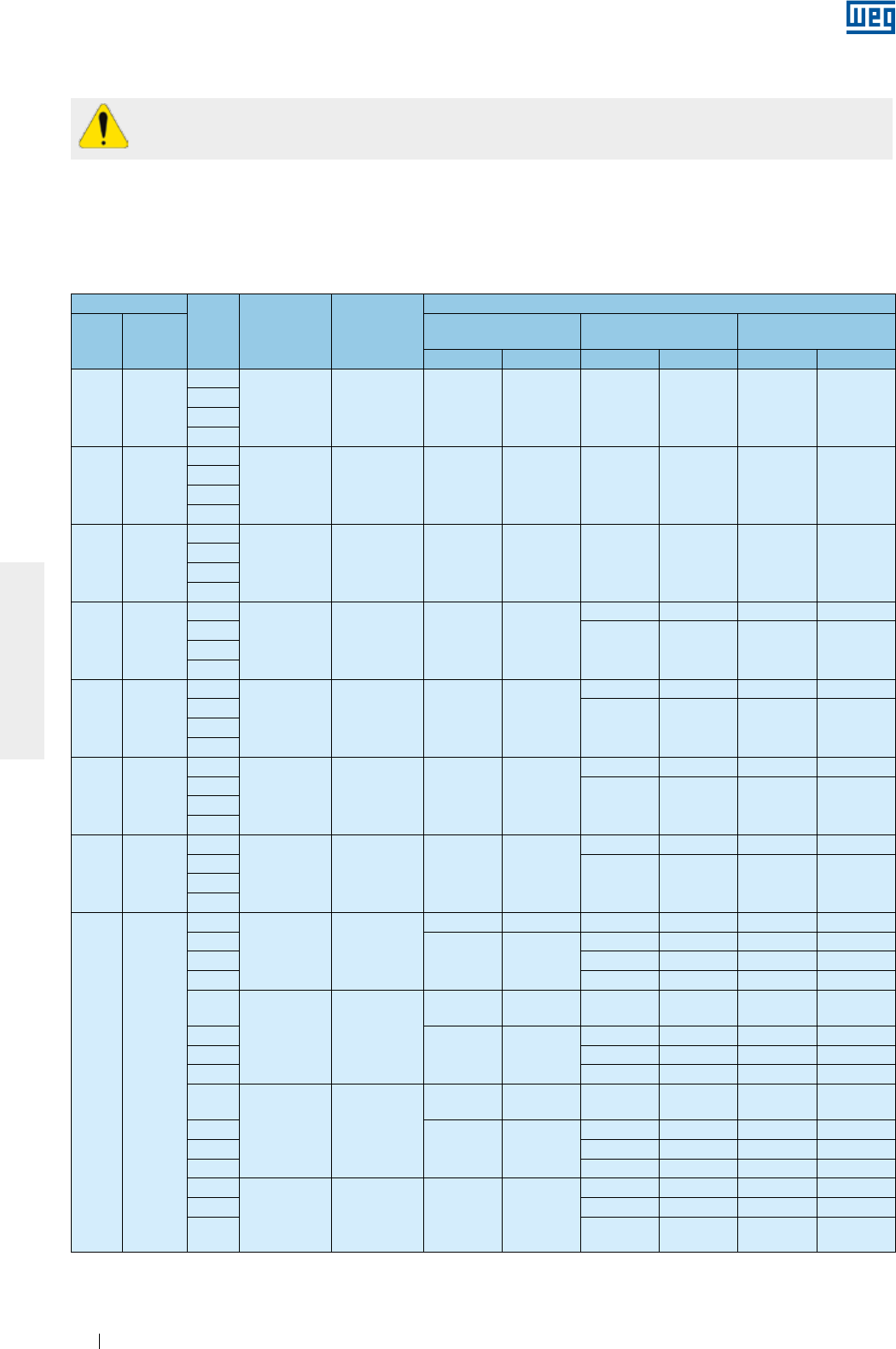
www.weg.net
Motores Elétricos46
PORTUGUÊS
Graxa em excesso provoca aquecimento do mancal e sua consequente falha.
8.2.1. Mancais de rolamento lubrificados a graxa
Os intervalos de lubrificação especificados nas Tabela 8.1, Tabela 8.2, Tabela 8.3 e Tabela 8.4 consideram uma
temperatura absoluta do mancal de 70 °C (até a carcaça IEC 200 / NEMA 324/6) e 85 °C (a partir da carcaça
IEC 225 / NEMA 364/5), rotação nominal do motor, instalação horizontal e graxa Mobil Polyrex EM. Qualquer
variação dos parâmetros indicados acima deve ser avaliada pontualmente.
Tabela 8.1- Intervalo de lubrificação para rolamentos de esferas.
Carcaça
Polos Rolamento Quantidade
de graxa (g)
Intervalos de relubrificação (horas)
IEC NEMA
ODP
(invólucro aberto)
W21
(invólucro Fechado)
W22
(invólucro Fechado)
50 Hz 60 Hz 50 Hz 60 Hz 50 Hz 60 Hz
90 143/5
2
6205 4 - - 20000 20000 25000 25000
4
6
8
100 -
2
6206 5 - - 20000 20000 25000 25000
4
6
8
112 182/4
2
6207/
6307 9 - - 20000 20000 25000 25000
4
6
8
132 213/5
2
6308 11 - -
20000 18400 25000 23200
4
20000 20000 25000 250006
8
160 254/6
2
6309 13 20000 20000
18100 15700 22000 20000
4
20000 20000 25000 250006
8
180 284/6
2
6311 18 20000 20000
13700 11500 17000 14000
4
20000 20000 25000 250006
8
200 324/6
2
6312 21 20000 20000
11900 9800 15000 12000
4
20000 20000 25000 250006
8
225
250
280
315
355
364/5
404/5
444/5
445/7
447/9
L447/9
504/5
5008
5010/11
586/7
588/9
2
6314 27
18000 14400 4500 3600 5000 4000
4
20000 20000
11600 9700 14000 12000
6 16400 14200 20000 17000
8 19700 17300 24000 20000
2
6316 34
14000 *Mediante
consulta 3500 *Mediante
consulta 4000 *Mediante
consulta
4
20000 20000
10400 8500 13000 10000
6 14900 12800 18000 16000
8 18700 15900 20000 20000
2
6319 45
9600 *Mediante
consulta 2400 *Mediante
consulta 3000 *Mediante
consulta
4
20000 20000
9000 7000 11000 8000
6 13000 11000 16000 13000
8 17400 14000 20000 17000
4
6322 60 20000 20000
7200 5100 9000 6000
6 10800 9200 13000 11000
8 15100 11800 19000 14000
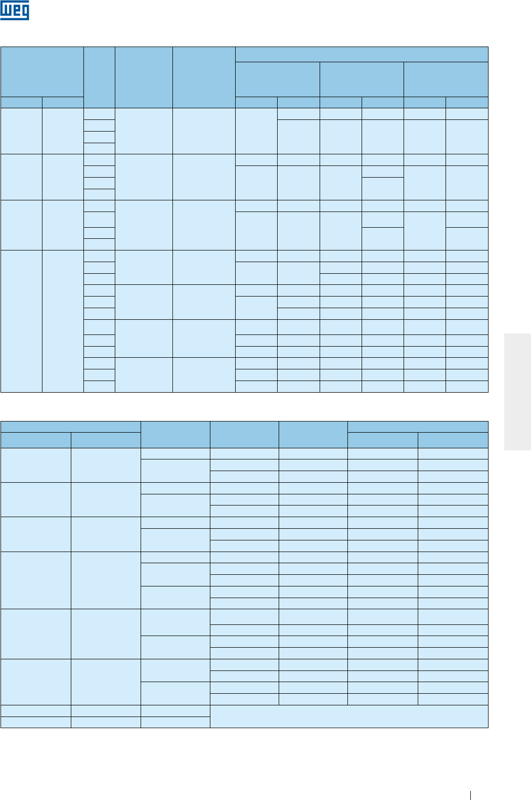
www.weg.net
Motores Elétricos 47
PORTUGUÊS
Tabela 8.2-
Intervalo de lubrificação para rolamentos de rolos
Carcaça Polos Rolamento Quantidade
de graxa (g)
Intervalos de relubrificação (horas)
ODP
(invólucro aberto)
W21
(invólucro Fechado)
W22
(invólucro Fechado)
IEC NEMA 50 Hz 60 Hz 50 Hz 60 Hz 50 Hz 60 Hz
160 254/6
2
NU309 13 20000
19600 13300 9800 16000 12000
4
20000 20000 20000 25000 250006
8
180 284/6
2
NU311 18
18400 12800 9200 6400 11000 8000
4
20000 20000 20000
19100
25000 250006 20000
8
200 324/6
2
NU312 21
15200 10200 7600 5100 9000 6000
4
20000 20000 20000
17200
25000
21000
620000 25000
8
225
250
280
315
355
364/5
404/5
444/5
445/7
447/9
L447/9
504/5
5008
5010/11
586/7
588/9
4
NU314 27
17800 14200 8900 7100 11000 9000
620000 20000 13100 11000 16000 13000
8 16900 15100 20000 19000
4
NU316 34
15200 12000 7600 6000 9000 7000
620000 19000 11600 9500 14000 12000
8 20000 15500 13800 19000 17000
4
NU319 45
12000 9400 6000 4700 7000 5000
6 19600 15200 9800 7600 12000 9000
8 20000 20000 13700 12200 17000 15000
4
NU322 60
8800 6600 4400 3300 5000 4000
6 15600 11800 7800 5900 9000 7000
8 20000 20000 11500 10700 14000 13000
Tabela 8.3 - Intervalo de lubrificação para rolamento de esferas - linha HGF
Carcaça Polos Rolamento Quantidade de
graxa (g)
Intervalos de lubrificação (horas)
IEC NEMA 50 Hz 60 Hz
315L/A/B e
315C/D/E
5006/7/8T e
5009/10/11T
2 6314 27 3100 2100
4 - 8 6320 50 4500 4500
6316 34 4500 4500
355L/A/B e
355C/D/E
5807/8/9T e
5810/11/12T
2 6314 27 3100 2100
4 - 8 6322 60 4500 4500
6319 45 4500 4500
400L/A/B e
400 C/D/E
6806/7/8T e
6809/10/11T
2 6315 30 2700 1800
4 - 8 6324 72 4500 4500
6319 45 4500 4500
450 7006/10
2 6220 31 2500 1400
46328 93 4500 3300
6322 60 4500 4500
6 - 8 6328 93 4500 4500
6322 60 4500 4500
500 8006/10
46330 104 4200 2800
6324 72 4500 4500
6 - 8 6330 104 4500 4500
6324 72 4500 4500
500 8006/10
46330 104 4200 2800
6324 72 4500 4500
6 - 8 6330 104 4500 4500
6324 72 4500 4500
560 8806/10 4 - 8 *Mediante consulta
630 9606/10 4 - 8
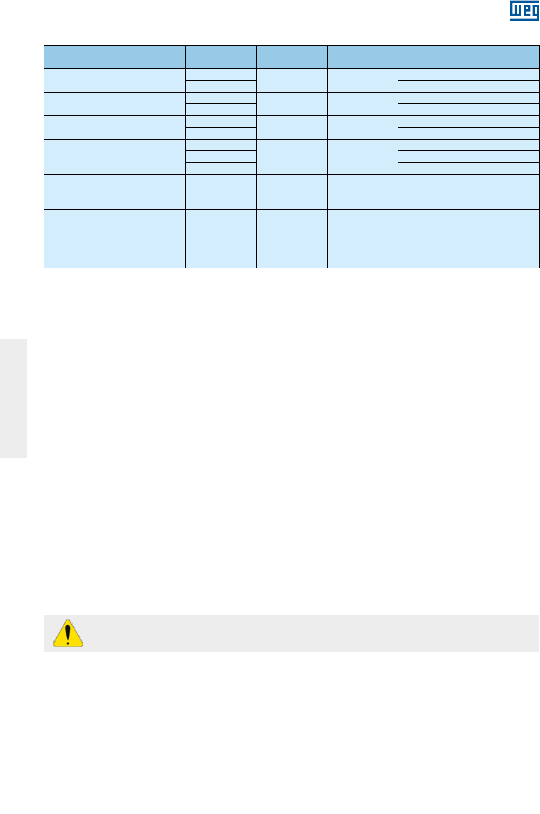
www.weg.net
Motores Elétricos48
PORTUGUÊS
Tabela 8.4 - Intervalo de lubrificação para rolamento de rolos - linha HGF
Carcaça Polos Rolamento Quantidade de
graxa (g)
Intervalos de lubrificação (horas)
IEC NEMA 50 Hz 60 Hz
315L/A/B e
315C/D/E
5006/7/8 e
5009/10/11
4NU320 50 4300 2900
6 - 8 4500 4500
355L/A/B e
355C/D/E
5807/8/9 e
5810/11/12
4NU322 60 3500 2200
6 - 8 4500 4500
400L/A/B e
400C/D/E
6806/7/8 e
6809/10/11
4NU324 72 2900 1800
6 - 8 4500 4500
450 7006/10
4
NU328 93
2000 1400
6 4500 3200
8 4500 4500
500 8006/10
4
NU330 104
1700 1000
6 4100 2900
8 4500 4500
560 8806/10 4NU228 + 6228 75 2600 1600
6 - 8 106 4500 4500
630 9606/10
4
NU232 + 6232
92 1800 1000
6 120 4300 3100
8 140 4500 4500
Para cada incremento de 15 °C na temperatura do mancal, o intervalo de relubrificação deverá ser reduzido
pela metade.
Motores originais de fábrica para posição horizontal, porém instalados na posição vertical (com autorização da
WEG) devem ter seu intervalo de relubrificação reduzido pela metade.
Para aplicações especiais, tais como: altas e baixas temperaturas, ambientes agressivos, variação de
velocidade (acionamento por inversor de frequência), etc., entre em contato com a WEG para obter
informações referentes ao tipo de graxa e intervalos de lubrificação a serem utilizados.
8.2.1.1. Motores sem graxeira
Nos motores sem graxeira, a lubrificação deve ser efetuada conforme plano de manutenção preventiva
existente. A desmontagem e montagem do motor deve ser feita conforme item 8.3.
Motores com rolamentos blindados (por exemplo, ZZ, DDU, 2RS, VV) devem ter os rolamentos substituídos ao
final da vida útil da graxa.
8.2.1.2. Motores com graxeira
Para relubrificação dos rolamentos com o motor parado, deve-se proceder da seguinte maneira:
gLimpar as proximidades do orifício de entrada de graxa;
g
Colocar aproximadamente metade da graxa total recomendada na placa de identificação do motor e girar o
motor durante aproximadamente 1 (um) minuto na rotação nominal;
gDesligar o motor e colocar o restante da graxa;
gRecolocar a proteção de entrada de graxa.
Para relubrificação dos rolamentos com o motor em operação, deve-se proceder da seguinte maneira:
gLimpar as proximidades do orifício de entrada de graxa;
gColocar a quantidade total de graxa recomendada na placa de identificação do motor;
gRecolocar a proteção de entrada de graxa.
Para lubrificação, é indicado o uso de lubrificador manual.
Nos motores fornecidos com dispositivo de mola, o excesso de graxa deve ser removido, puxando a vareta da
mola e limpando a mola, até que a mesma não contenha mais graxa.
8.2.1.3. Compatibilidade da graxa Mobil Polyrex EM com outras graxas
A graxa Mobil Polyrex EM possui espessante de poliuréia e óleo mineral, e é compatível com outras graxas
que contenham:
g
Espessante de lítio ou complexo de lítio ou poliuréia e óleo mineral altamente refinado;
g
A graxa aplicada deve possuir em sua formulação aditivos inibidores de corrosão e oxidação.
Apesar da graxa Mobil Polyrex EM ser compatível com os tipos de graxa indicados acima, não é recomendada
a mistura de graxas.
Caso necessite de outro tipo de graxa, contate a WEG.
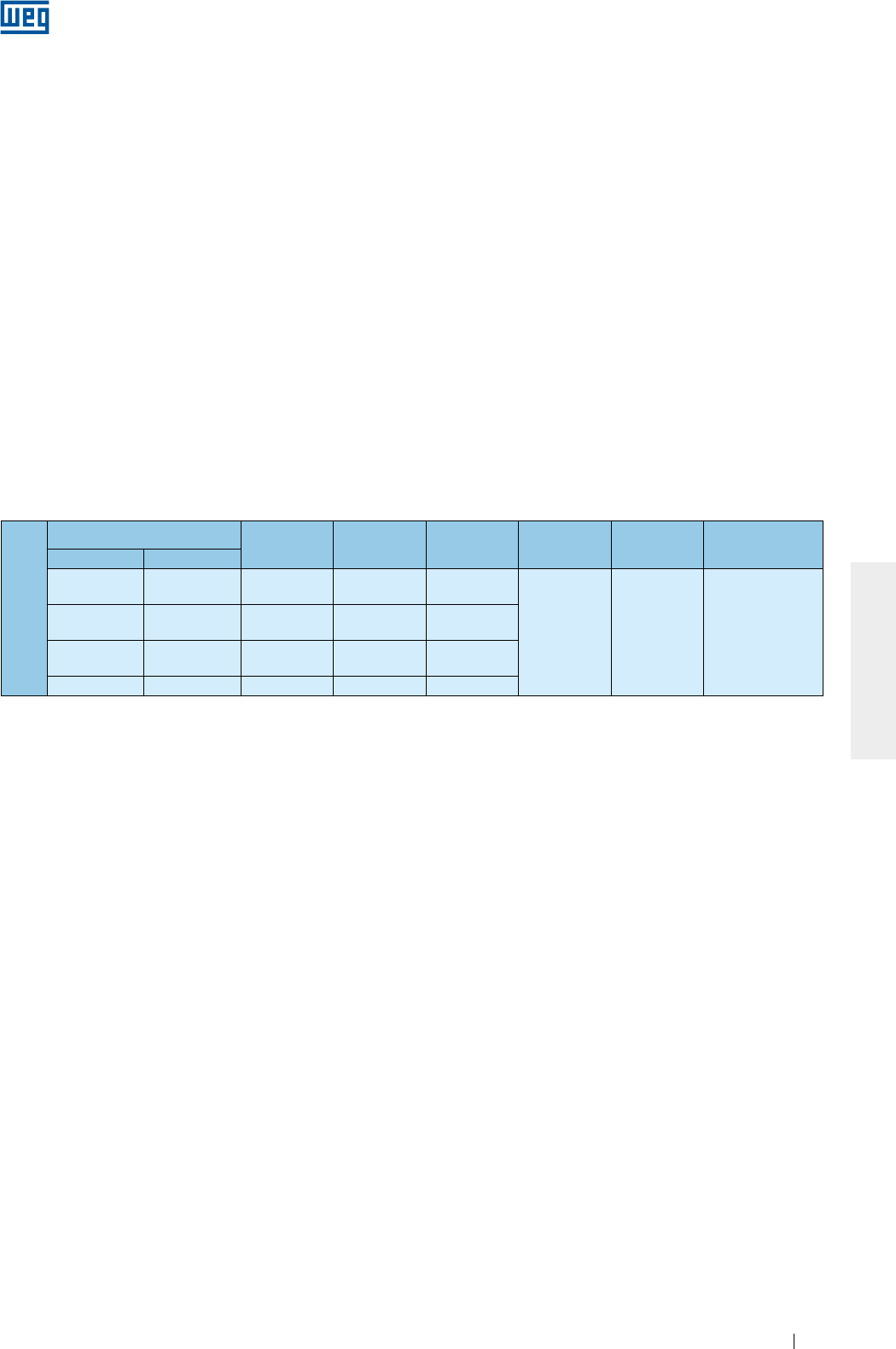
www.weg.net
Motores Elétricos 49
PORTUGUÊS
Tabela 8.5 - Características de lubrificação para motores HGF vertical de alto empuxo
8.2.2. Mancais de rolamento lubrificados a óleo
Nos motores com rolamento lubrificados a óleo, a troca de óleo deve ser feita com o motor parado, seguindo
os procedimento a seguir:
g
Abrir o respiro da entrada de óleo;
g
Retirar o tampão de saída de óleo;
g
Abrir a válvula e drenar todo o óleo;
g
Fechar a válvula;
g
Recolocar o tampão;
g
Preencher com a quantidade e especificação do óleo indicados na placa de identificação;
g
Verificar se o nível do óleo está na metade do visor;
g
Fechar o respiro da entrada de óleo;
g
Certificar-se que não há vazamento e que todos os furos roscados não utilizados estejam fechados.
A troca de óleo dos mancais deve ser realizada no intervalo indicado na placa de identificação ou sempre que
o lubrificante apresentar alterações em suas características (viscosidade, pH, etc.).
O nível de óleo deve ser mantido na metade do visor de óleo e acompanhado diariamente.
O uso de lubrificantes com outras viscosidades requer contato prévio com a WEG.
Obs: motores HGF verticais para alto empuxo são fornecidos com mancais dianteiros lubrificados a graxa e
com mancais traseiros, a óleo. Os mancais dianteiros devem seguir as recomendações do item 8.2.1. A Tabela
8.5 apresenta a quantidade e especificação de óleo para essa configuração.
Montagem alto empuxo
Carcaça Polos Rolamento Óleo (L) Intervalo (h) Lubrificante Especificação
lubrificante
IEC NEMA
315L/A/B e
315C/D/E
5006/7/8T e
5009/10/11T 4 - 8 29320 20
8000
Renolin
DTA 40 /
SHC 629
Óleo mineral ISO
VG150 com
aditivos
anti-espuma
e
antioxidantes
355L/A/B e
355C/D/E
5807/8/9T e
5810/11/12T 4 - 8 29320 26
400L/A/B e
400C/D/E
6806/7/8T e
6809/10/11T 4 - 8 29320 37
450 7006/10 4 - 8 29320 45
8.2.3. Mancais de rolamento com lubrificação do tipo
Oil Mist
Verificar o estado das vedações e, sempre que for necessária alguma troca, usar apenas peças originais.
Realizar a limpeza dos componentes antes da montagem (anéis de fixação, tampas, etc.).
Aplicar veda juntas resistente ao óleo lubrificante utilizado, entre os anéis de fixação e as tampas.
A conexão dos sistemas de entrada, saída e dreno de óleo devem ser realizados conforme Figura 6.12.
8.2.4. Mancais de deslizamento
Para os mancais de deslizamento, a troca de óleo deve ser feita nos intervalos indicados na
Tabela 8.6 e deve ser realizada, adotando os seguintes procedimentos:
gPara o mancal traseiro, retirar a tampa de inspeção da defletora;
gDrenar o óleo através do dreno localizado na parte inferior da carcaça do mancal (conforme Figura 8.1);
gFechar a saída de óleo;
gRetirar o bujão da entrada de óleo;
g
Preencher com o óleo especificado e com a quantidade indicada na Tabela 8.6;
g
Verificar se o nível do óleo está na metade do visor;
gFechar a entrada de óleo;
g
Certificar-se que não há vazamento.
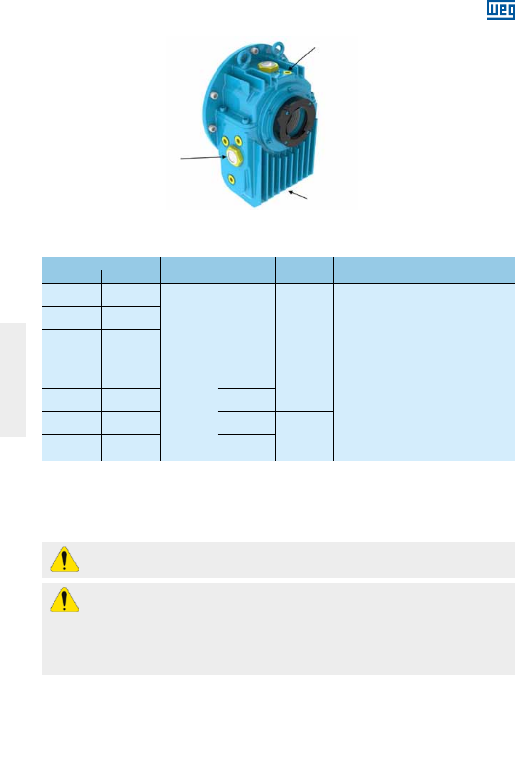
www.weg.net
Motores Elétricos50
PORTUGUÊS
Entrada de óleo
Saída de óleo
Visor do nível de óleo
Figura 8.1 - Mancal de deslizamento
Tabela 8.6 - Características de lubrificação para mancais de deslizamento
Carcaça Polos Mancal Óleo (L) Intervalo (h) Lubrificante Especificação
lubrificante
IEC NEMA
315L/A/B e
315C/D/E
5006/7/8T e
5009/10/11T
2 9-80 2.8 8000 Renolin
DTA 10
Óleo mineral
ISO VG32 com
aditivos
anti-espuma e
antioxidantes
355L/A/B e
355C/D/E
5807/8/9T e
5810/11/12T
400L/A/B e
400C/D/E
6806/7/8T e
6809/10/11T
450 7006/10
315L/A/B e
315C/D/E
5006/7/8T e
5009/10/11T
4 - 8
9-90
2.8
8000 Renolin DTA
15
Óleo mineral
ISO VG46 com
aditivos
anti-espuma e
antioxidantes
355L/A/B e
355C/D/E
5807/8/9T e
5810/11/12T 9-100
400L/A/B e
400C/D/E
6806/7/8T e
6809/10/11T 11-110
4.7
450 7006/10 11-125
500 8006/10
A troca de óleo dos mancais deve ser realizada no intervalo indicado na placa de identificação ou sempre que
o lubrificante apresentar alterações em suas características (viscosidade, pH, etc.).
O nível de óleo deve ser mantido na metade do visor e acompanhado diariamente.
Não poderão ser usados lubrificantes com outras viscosidades sem antes consultar a WEG.
8.3. DESMONTAGEM E MONTAGEM
Serviços de reparo em motores devem ser efetuados apenas por pessoal capacitado seguindo as
normas vigentes no país. Devem ser utilizados somente ferramentas e métodos adequados.
Qualquer serviço de desmontagem e montagem deve ser realizado com o motor totalmente
desenergizado e completamente parado.
Mesmo o motor desligado pode apresentar energia elétrica no interior da caixa de ligação, nas resistências
de aquecimento, no enrolamento e nos capacitores.
Motores acionados por inversor de frequência podem estar energizados mesmo com o motor parado.
Antes de iniciar o procedimento de desmontagem, registrar as condições atuais da instalação, tais como
conexões dos terminais de alimentação do motor e alinhamento/nivelamento que devem ser considerados
durante a posterior montagem.
Realizar a desmontagem de maneira cuidadosa, sem causar impactos contra as superfícies usinadas e/ou nas
roscas.
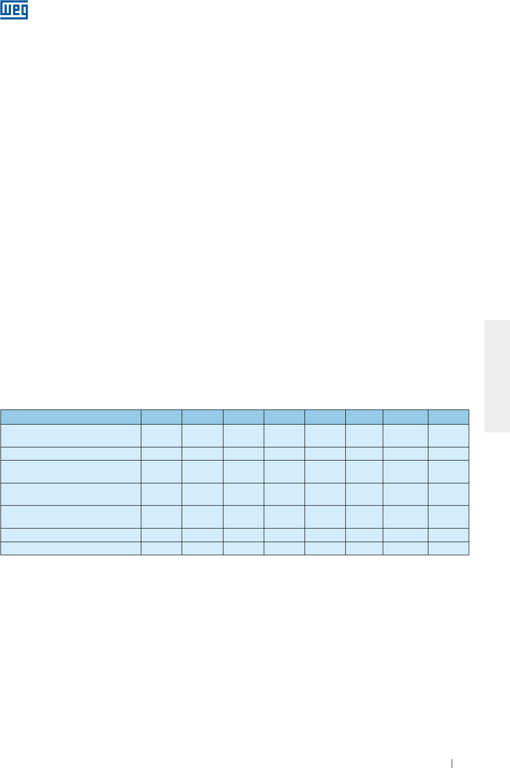
www.weg.net
Motores Elétricos 51
PORTUGUÊS
Montar o motor em uma superfície plana para garantir uma boa base de apoio. Motores sem pés devem ser
calçados/travados para evitar acidentes.
Cuidados adicionais devem ser tomados para não danificar as partes isoladas que operam sob tensão elétrica,
como por exemplo, enrolamentos, mancais isolados, cabos de alimentação, etc..
Elementos de vedação, por exemplo, juntas e vedações dos mancais devem ser trocados sempre que
apresentarem desgaste ou estiverem danificados.
Motores com grau de proteção superior ao IP55 são fornecidos com produto vedante Loctite 5923 (Henkel)
nas juntas e parafusos. Antes de montar os componentes, limpar as superfícies e aplicar uma nova camada
deste produto.
8.3.1. Caixa de ligação
Ao retirar a tampa da caixa de ligação para a conexão/desconexão dos cabos de alimentação e acessórios,
devem ser adotados os seguintes cuidados:
g
Assegurar que durante a remoção dos parafusos, a tampa da caixa não danifique os componentes
instalados em seu interior;
g
Caso a caixa de ligação seja fornecida com olhal de suspensão, este deve ser utilizado para movimentar a
tampa da caixa de ligação;
g
Para motores fornecidos com placa de bornes, devem ser assegurados os torques de aperto especificados
na Tabela 8.7;
g
Assegurar que os cabos não entrem em contato com superfícies com cantos vivos;
g
Adotar os devidos cuidados para garantir que o grau de proteção inicial, indicado na placa de identificação
do motor não seja alterado. As entradas de cabos para a alimentação e controle devem utilizar sempre
componentes (como por exemplo, prensa-cabos e eletrodutos) que atendam as normas e regulamentações
vigentes de cada país;
g
Assegurar que a janela de alívio de pressão (quando houver) não esteja danificada. As juntas de vedação da
caixa de ligação devem estar em perfeito estado para reutilização e devem ser posicionadas corretamente
para garantir o grau de proteção;
gAssegurar os torques de aperto dos parafusos de fixação da tampa da caixa conforme Tabela 8.7.
Tabela 8.7 - Torques de aperto para elementos de fixação [Nm]
Tipo de parafuso e Junta M4 M5 M6 M8 M10 M12 M16 M20
Parafuso sextavado externo/interno
(s/ junta) - 4 a 7 7 a 12 16 a 30 30 a 50 55 a 85 120 a 180 230 a
360
Parafuso fenda combinada (s/ junta) - 3 a 5 5 a 10 10 a 18 - - - -
Parafuso sextavado externo/interno
(c/ junta com batente metálico/cordão) - - - 13 a 20 25 a 37 40 a 55 50 a 65 -
Parafuso fenda combinada (c/ junta
plana e/ou batente metálico/cordão) - 3 a 5 4 a 8 8 a 15 - - - -
Parafuso sextavado externo/interno
(c/ junta plana) - - - 8 a 15 18 a 30 25 a 40 35 a 50 -
Placa de bornes 1 a 1,5 1,5 a 4 3 a 6,5 6 a 9 10 a 18 15,5 a 30 30 a 50 -
Aterramento - 3 a 5 5 a 10 10 a 18 30 a 50 55 a 85 120 a 180 -
8.4. PROCEDIMENTO PARA ADEQUAÇÃO DA RESISTÊNCIA DE ISOLAMENTO
O motor deve ser desmontado e suas tampas, rotor completo (com eixo), ventilador, defletora e caixa de
ligação devem ser separados, de modo que apenas a carcaça com o estator passe por um processo de
secagem em uma estufa apropriada, por um período de duas horas, a uma temperatura não superior a 120ºC.
Para motores maiores, pode ser necessário aumentar o tempo de secagem. Após esse período de secagem,
deixar o estator resfriar até a temperatura ambiente e repetir a medição da resistência de isolamento, conforme
item 5.4. Caso necessário, deve-se repetir o processo de secagem do estator.
Se, mesmo após repetidos processos de secagem do estator, a resistência de isolamento não voltar aos níveis
aceitáveis, recomenda-se fazer uma análise criteriosa das causas que levaram à queda do isolamento do
enrolamento e, eventualmente poderá culminar com o rebobinamento do motor.
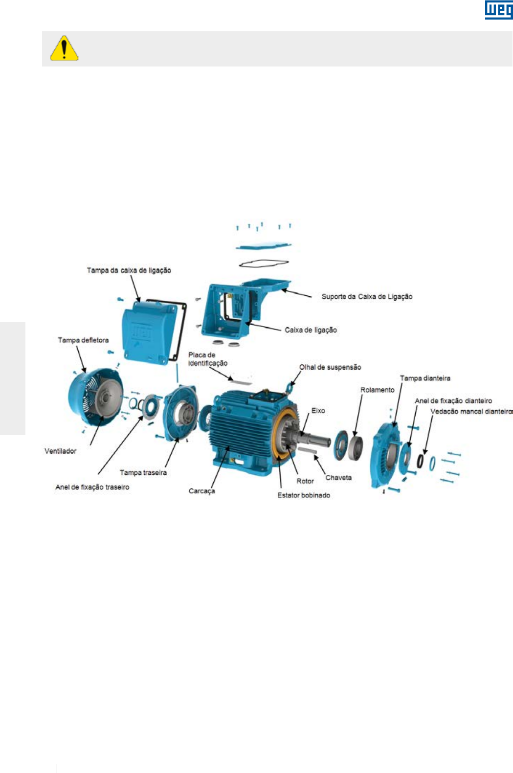
www.weg.net
Motores Elétricos52
PORTUGUÊS
Para evitar o risco de choque elétrico, descarregue os terminais imediatamente antes e depois de
cada medição. Caso o motor possua capacitores, estes devem ser descarregados.
8.5. PARTES E PEÇAS
Ao solicitar peças para reposição, informar a designação completa do motor, bem como seu código e número
de série, que podem ser encontrados na placa de identificação do motor.
Partes e peças devem ser adquiridas da rede de Assistência Técnica Autorizada WEG. O uso de peças não
originais pode resultar na queda do desempenho e causar a falha no motor.
As peças sobressalentes devem ser armazenadas em local seco com uma umidade relativa do ar de até 60%,
com temperatura ambiente maior que 5 °C e menor que 40 °C, isento de poeira, vibrações, gases, agentes
corrosivos, sem variações bruscas da temperatura, em sua posição normal e sem apoiar sobre as mesmas
outros objetos.
Figura 8.2 -
Vista explodida dos componentes de um motor W22

www.weg.net
Motores Elétricos 53
PORTUGUÊS
9. INFORMAÇÕES AMBIENTAIS
9.1. EMBALAGEM
Os motores elétricos são fornecidos em embalagens de papelão, plástico ou de madeira. Estes materiais são
recicláveis ou reutilizáveis e devem receber o destino certo conforme as normas vigentes de cada país. Toda a
madeira utilizada nas embalagens dos motores WEG provém de reflorestamento e não é submetida a nenhum
tratamento químico para a sua conservação.
9.2. PRODUTO
Os motores elétricos, sob o aspecto construtivo, são fabricados essencialmente com metais ferrosos (aço,
ferro fundido), metais não ferrosos (cobre, alumínio) e plástico.
O motor elétrico, de maneira geral, é um produto que possui vida útil longa, porém quando for necessário seu
descarte, a WEG recomenda que os materiais da embalagem e do produto sejam devidamente separados e
encaminhados para reciclagem.
Os materiais não recicláveis devem, como determina a legislação ambiental, ser dispostos de forma adequada,
ou seja, em aterros industriais, co-processados em fornos de cimento ou incinerados. Os prestadores de
serviços de reciclagem, disposição em aterro industrial, co-processamento ou incineração de resíduos devem
estar devidamente licenciados pelo órgão ambiental de cada estado para realizar estas atividades.
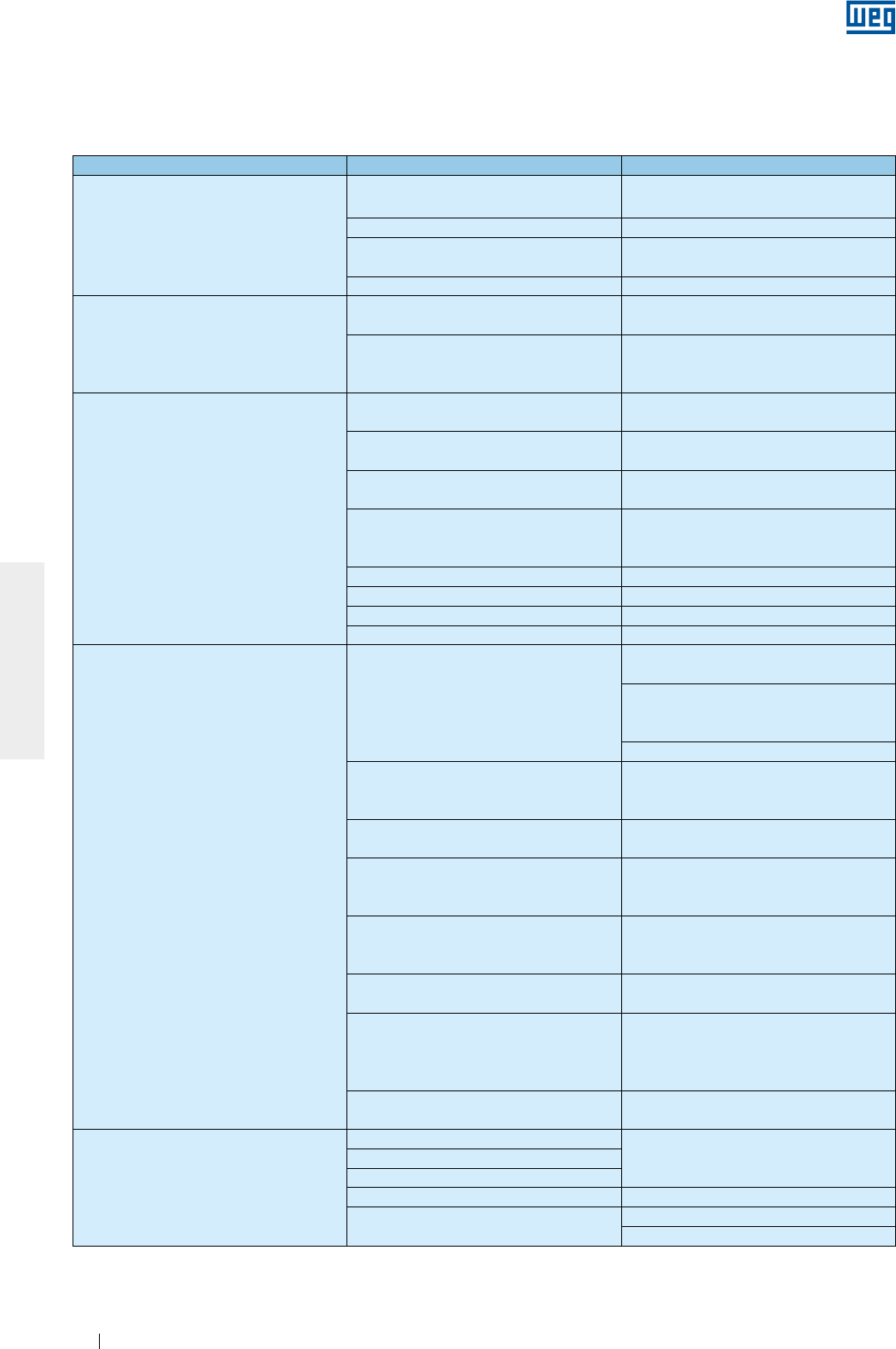
www.weg.net
Motores Elétricos54
PORTUGUÊS
10. PROBLEMAS X SOLUÇÕES
As instruções a seguir apresentam uma relação de problemas comuns com possíveis soluções. Em caso de
dúvida, contatar o Assistente Técnico Autorizado ou a WEG.
Problema Possíveis causas Solução
Motor não parte, nem acoplado e nem
desacoplado
Interrupção na alimentação do motor Verificar o circuito de comando e os cabos
de alimentação do motor
Fusíveis queimados Substituir os fusíveis
Erro na conexão do motor Corrigir as conexões do motor conforme
diagrama de conexão
Mancal travado Verificar se o mancal gira livremente
Quando acoplado com carga, o motor não
parte ou parte muito lentamente e não
atinge rotação nominal
Carga com torque muito elevado durante a
partida
Não aplicar carga na máquina acionada
durante a partida
Queda de tensão muito alta nos cabos de
alimentação
Verificar o dimensionamento da instalação
(transformador, seção dos cabos, relés,
disjuntores, etc.)
Ruído elevado/anormal
Defeito nos componentes de transmissão
ou na máquina acionada
Verificar a transmissão de força, o
acoplamento e o alinhamento
Base desalinhada/desnivelada Realinhar/nivelar o motor e a máquina
acionada
Desbalanceamento dos componentes ou
da máquina acionada Refazer balanceamento
Tipos diferentes de balanceamento entre
motor e acoplamento (meia chaveta,
chaveta inteira)
Refazer balanceamento
Sentido de rotação do motor errado Inverter o sentido de rotação do motor
Parafusos de fixação soltos Reapertar os parafusos
Ressonância da fundação Verificar o projeto da fundação
Rolamentos danificados Substituir o rolamento
Aquecimento excessivo no motor
Refrigeração insuficiente
Limpar as entradas e saídas de ar da
defletora e da carcaça
Verificar as distâncias mínimas entre a
entrada da defletora de ar e paredes
próximas(conforme item 7)
Verificar temperatura do ar na entrada
Sobrecarga
Medir a corrente do motor, analisando sua
aplicação e, se necessário, diminuir a
carga.
Excessivo número de partidas ou momento
de inércia da carga muito elevado Reduzir o número de partidas
Tensão muito alta
Verificar a tensão de alimentação do motor.
Não ultrapassar a tolerância conforme item
7.2
Tensão muito baixa
Verificar a tensão de alimentação e a queda
de tensão no motor. Não ultrapassar a
tolerância (conforme item 7.2)
Interrupção de um cabo de alimentação Verificar a conexão de todos os cabos de
alimentação
Desequilíbrio de tensão nos terminais de
alimentação do motor
Verificar se há fusíveis queimados,
comandos errados, desequilíbrio nas
tensões da rede de alimentação, falta de
fase ou nos cabos de ligação
Sentido de rotação não compatível com o
ventilador unidirecional
Verificar sentido de rotação conforme
marcação do motor
Aquecimento do mancal
Graxa/óleo em demasia Fazer limpeza do mancal e lubrificar
segundo as recomendações
Envelhecimento da graxa/óleo
Utilização de graxa/óleo não especificados
Falta de graxa/óleo Lubrificar segundo as recomendações
Excessivo esforço axial ou radial Reduzir tensão nas correias
Redimensionar a carga aplicada ao motor
www.weg.net
Motores Elétricos 55
PORTUGUÊS
11. TERMO DE GARANTIA
A WEG Equipamentos Elétricos S/A, Unidade Motores (“WEG”), oferece garantia contra defeitos de fabricação
e de materiais para seus produtos por um período de 18 meses, contados a partir da data de emissão da nota
fiscal da fábrica ou do distribuidor/revendedor, limitado a 24 meses da data de fabricação.
Para os motores da linha HGF, a garantia oferecida é de 12 meses, contados a partir da data de emissão da
nota fiscal da fábrica ou do distribuidor/revendedor, limitado a 18 meses a partir da data de fabricação.
Nos prazos de garantia acima estão contidos os prazos de garantia legal, não sendo cumulativos entre si.
Caso um prazo de garantia diferenciado estiver definido na proposta técnico-comercial para determinado
fornecimento, este prevalecerá sobre os prazos acima.
Os prazos estabelecidos acima independem da data de instalação do produto e de sua entrada em operação.
Na ocorrência de um desvio em relação à operação normal do produto, o cliente deve comunicar
imediatamente por escrito à WEG sobre os defeitos ocorridos, e disponibilizar o produto para a WEG ou seu
Assistente Técnico Autorizado pelo prazo necessário para a identificação da causa do desvio, verificação da
cobertura da garantia, e para o devido reparo.
Para ter direito à garantia, o cliente deve atender às especificações dos documentos técnicos da WEG,
especialmente àquelas previstas no Manual de Instalação, Operação e Manutenção dos produtos, e às
normas e regulamentações vigentes em cada país.
Não possuem cobertura da garantia os defeitos decorrentes de utilização, operação e/ou instalação
inadequadas ou inapropriadas dos equipamentos, sua falta de manutenção preventiva, bem como defeitos
decorrentes de fatores externos ou equipamentos e componentes não fornecidos pela WEG.
A garantia não se aplica se o cliente, por própria iniciativa, efetuar reparos e/ou modificações no equipamento
sem prévio consentimento por escrito da WEG.
A garantia não cobre equipamentos, partes e/ou componentes, cuja vida útil for inferior ao período de garantia.
Não cobre, igualmente, defeitos e/ou problemas decorrentes de força maior ou outras causas que não podem
ser atribuídas à WEG, como por exemplo, mas não limitado a: especificações ou dados incorretos ou
incompletos por parte do cliente, transporte, armazenagem, manuseio, instalação, operação e manutenção em
desacordo com as instruções fornecidas, acidentes, deficiências de obras civis, utilização em aplicações e/ou
ambientes para os quais o produto não foi projetado, equipamentos e/ou componentes não incluídos no
escopo de fornecimento da WEG. A garantia não inclui os serviços de desmontagem nas instalações do
cliente, os custos de transporte do produto e as despesas de locomoção, hospedagem e alimentação do
pessoal da Assistência Técnica, quando solicitados pelo cliente.
Os serviços em garantia serão prestados exclusivamente em oficinas de Assistência Técnica autorizadas pela
WEG ou na sua própria fábrica. Em nenhuma hipótese, estes serviços em garantia prorrogarão os prazos de
garantia do equipamento.
A responsabilidade civil da WEG está limitada ao produto fornecido, não se responsabilizando por danos
indiretos ou emergentes, tais como lucros cessantes, perdas de receitas e afins que, porventura, decorrerem
do contrato firmado entre as partes.

www.weg.net
Motores Elétricos56
PORTUGUÊS
12. DECLARAÇÃO DE CONFORMIDADE CE
WEG Equipamentos Elétricos S/A
Av. Prefeito Waldemar Grubba, 3000
89256-900 - Jaraguá do Sul – SC – Brasil,
e seu representante autorizado estabelecido na Comunidade Européia,
WEGeuro – Industria Electrica SA
Contato: Luís Filipe Oliveira Silva Castro Araújo
Rua Eng Frederico Ulrich, Apartado 6074
4476-908 – Maia – Porto – Portugal
declaram por meio desta, que os produtos:
Motores de indução WEG e componentes para uso nestes motores:
Trifásicos
Carcaças IEC 63 a 630
Carcaças NEMA 42, 48, 56 e 143 a 9610
...............
Monofásicos
Carcaças IEC 63 a 132
Carcaças NEMA 42, 48, 56 e 143 a 215
...............
quando instalados, mantidos e utilizados em aplicações para os quais foram projetados e quando consideradas as
normas de instalação e instruções do fabricante pertinentes, eles atendem os requisitos das seguintes Diretivas Européias
e normas aplicáveis:
Diretivas:
Diretiva de Baixa Tensão 2006/95/CE*
Regulamento (CE) No 640/2009*
Diretiva 2009/125/CE*
Diretiva de Máquinas 2006/42/CE**
Diretiva de Compatibilidade Eletromagnética 2004/108/CE (motores de indução são considerados intrinsecamente
benignos em termos de compatibilidade eletromagnética)
Normas:
EN 60034-1:2010/ EN 60034-2-1:2007/EN 60034-5:2001/A1:2007/ EN 60034-6:1993/ EN 60034-7:1993/A1:2001/
EN 60034-8:2007/ EN 60034-9:2005/A1:2007/ EN 60034-11:2004/ EN 60034-12:2002/A1:2007/
EN 60034-14:2004/A1:2007/ EN 60034-30:2009, EN 60204-1:2006/AC:2010 e EN 60204-11:2000/AC:2010
Marca CE em: 1996
* Motores elétricos projetados para uso com tensão superior a 1000 V não são considerados dentro do escopo.
** Motores elétricos de baixa tensão não são considerados dentro do escopo e motores elétricos projetados para uso com
tensão superior a 1000 V são considerados máquinas parcialmente completas e são fornecidas com uma
Declaração de Incorporação:
Os produtos acima não podem ser colocados em serviço até que a máquina, na qual serão incorporados, tenha sido
declarada em conformidade com a Diretiva de Máquinas.
A Documentação Técnica para os produtos acima é compilada de acordo com a parte B do Anexo VII da Diretiva de
Máquinas 2006/42/CE.
Nós nos comprometemos em transmitir, em resposta a um pedido fundamentado das autoridades nacionais, informação
relevante sobre a máquina parcialmente completa identificada acima, através do representante autorizado WEG
estabelecido na Comunidade Européia. O método de transmissão deve ser eletrônico ou físico e não deve ser prejudicial
aos diretos de propriedade intelectual do fabricante.
Milton Oscar Castella
Diretor de Engenharia
Jaraguá do Sul, 8 de Abril de 2013

www.weg.net
Manual of Electric Motors58
INSTALLATION, OPERATION AND MAINTENANCE
MANUAL OF ELECTRIC MOTORS
This manual provides information about WEG induction motors fitted with squirrel cage,
permanent magnet or hybrid rotors, low, medium and high voltage, in frame sizes IEC 56
to 630 and NEMA 42 to 9606/10.
The motor lines indicated below have additional information that can be checked in their
respective manuals:
g Smoke Extraction Motors;
g Electromagnetic Brake Motors;
g Hazardous Area Motors.
These motors meet the following standards, if applicable:
g NBR 17094-1: Máquinas Elétricas Girantes - Motores de Indução - Parte 1: trifásicos.
g NBR 17094-2: Máquinas Elétricas Girantes - Motores de Indução - Parte 2: monofásicos.
g IEC 60034-1: Rotating Electrical Machines - Part 1: Rating and Performance.
g NEMA MG 1: Motors and Generators.
g CSA C 22.2 N°100: Motors and Generators.
g UL 1004-1: Rotating Electrical Machines - General Requirements.
If you have any questions regarding this manual please contact your local WEG branch,
contact details can be found at www.weg.net.

www.weg.net
Manual of Electric Motors 59
ENGLISH
TABLE OF CONTENTS
1. TERMINOLOGY 61
2. INITIAL RECOMMENDATIONS 62
2.1. WARNING SYMBOL ......................................................................................................................... 62
2.2. RECEIVING INSPECTION ................................................................................................................ 62
2.3. NAMEPLATES ..................................................................................................................................63
3. SAFETY INSTRUCTIONS 66
4. HANDLING AND TRANSPORT 67
4.1. LIFTING .............................................................................................................................................. 67
4.1.1. Horizontal motors with one eyebolt ...................................................................................... 67
4.1.2. Horizontal motor with two eyebolts .....................................................................................68
4.1.3. Vertical motors ....................................................................................................................... 69
4.1.3.1. Procedures to place W22 motors in the vertical position ............................................... 69
4.1.3.2. Procedures to place HGF motors in the vertical position .............................................. 70
4.2 PROCEDURES TO PLACE W22 VERTICAL MOUNT MOTORS IN HORIZONTAL POSITION .... 71
5. STORAGE 73
5.1. EXPOSED MACHINED SURFACES ................................................................................................. 73
5.2. STORAGE .......................................................................................................................................... 73
5.3 BEARINGS ......................................................................................................................................... 74
5.3.1 Grease lubricated bearings .................................................................................................... 74
5.3.2 Oil lubricated bearings ........................................................................................................... 74
5.3.3 Oil Mist lubricated bearings ................................................................................................... 75
5.3.4 Sleeve bearing ......................................................................................................................... 75
5.4. INSULATION RESISTANCE ............................................................................................................. 75
5.4.1. Insulation resistance measurement ..................................................................................... 75
6. INSTALLATION 78
6.1. FOUNDATIONS ................................................................................................................................. 79
6.2. MOTOR MOUNTING ........................................................................................................................ 81
6.2.1. Foot mounted motors ............................................................................................................. 81
6.2.2. Flange mounted motors ........................................................................................................ 81
6.2.3. Pad mounted motors ............................................................................................................. 82
6.3. BALANCING ...................................................................................................................................... 82
6.4. COUPLINGS ...................................................................................................................................... 82
6.4.1. Direct coupling ........................................................................................................................ 83
6.4.2. Gearbox coupling ................................................................................................................... 83
6.4.3. Pulley and belt coupling ........................................................................................................ 83
6.4.4. Coupling of sleeve bearing motors ......................................................................................83
6.5. LEVELING .........................................................................................................................................84

www.weg.net
Manual of Electric Motors60
ENGLISH
6.6. ALIGNMENT ......................................................................................................................................84
6.7. CONNECTION OF OIL LUBRICATED OR OIL MIST LUBRICATED MOTORS ............................. 85
6.8. CONNECTION OF THE COOLING WATER SYSTEM .....................................................................85
6.9. ELECTRICAL CONNECTION ........................................................................................................... 85
6.10. CONNECTION OF THE THERMAL PROTECTION DEVICES ......................................................88
6.11. RESISTANCE TEMPERATURE DETECTORS (PT-100) ................................................................ 89
6.12. CONNECTION OF THE SPACE HEATERS .................................................................................... 91
6.13. STARTING METHODS .................................................................................................................... 92
6.14. MOTORS DRIVEN BY FREQUENCY INVERTER .......................................................................... 93
6.14.1. Use of dV/dt filter ...................................................................................................................93
6.14.1.1. Motor with enameled round wire ...................................................................................... 93
6.14.1.2. Motor with prewound coils ............................................................................................... 93
6.14.2. Bearing insulation ................................................................................................................. 94
6.14.3. Switching frequency .............................................................................................................94
6.14.4. Mechanical speed limitation ............................................................................................... 94
7. COMMISSIONING 95
7.1. INITIAL START-UP ........................................................................................................................... 95
7.2. OPERATING CONDITIONS ............................................................................................................. 97
7.2.1.Limits of vibration ................................................................................................................... 98
8. MAINTENANCE 99
8.1. GENERAL INSPECTION ...................................................................................................................99
8.2. LUBRICATION .................................................................................................................................. 99
8.2.1. Grease lubricated rolling bearings ..................................................................................... 100
8.2.1.1. Motor without grease fitting ............................................................................................. 102
8.2.1.2. Motor with grease fitting .................................................................................................. 102
8.2.1.3. Compatibility of the Mobil Polyrex EM grease with other greases ............................. 102
8.2.2. Oil lubricated bearings ........................................................................................................ 103
8.2.3. Oil mist lubricated bearings ................................................................................................ 103
8.2.4. Sleeve bearings .................................................................................................................... 103
8.3. MOTOR ASSEMBLY AND DISASSEMBLY ................................................................................... 104
8.3.1. Terminal box .......................................................................................................................... 105
8.4. DRYING THE STATOR WINDING INSULATION ........................................................................... 105
8.5. SPARE PARTS ................................................................................................................................ 106
9. ENVIRONMENTAL INFORMATION 107
9.1. PACKAGING .................................................................................................................................... 107
9.2. PRODUCT ....................................................................................................................................... 107
10. TROUBLESHOOTING CHART X SOLUTIONS 108
11. WARRANTY TERM 109
12. EC DECLARATION OF CONFORMITY 110
www.weg.net
Manual of Electric Motors 61
ENGLISH
1. TERMINOLOGY
Balancing: the procedure by which the mass distribution of a rotor is checked and, if necessary, adjusted to
ensure that the residual unbalance or the vibration of the journals and/or forces on the bearings at a frequency
corresponding to service speed are within specified limits in International Standards.
[ISO 1925:2001, definition 4.1]
Balance quality grade: indicates the peak velocity amplitude of vibration, given in mm/s, of a rotor running free-
in-space and it is the product of a specific unbalance and the angular velocity of the rotor at maximum
operating speed.
Grounded Part: metallic part connected to the grounding system.
Live Part: conductor or conductive part intended to be energized in normal operation, including a neutral
conductor.
Authorized personnel: employee who has formal approval of the company.
Qualified personnel: employee who meets the following conditions simultaneously:
g Receives training under the guidance and responsibility of a qualified and authorized professional;
g Works under the responsibility of a qualified and approved professional.
Note: The qualification is only valid for the company that trained the employee in the conditions set out by the authorized and qualified
professional responsible for training.
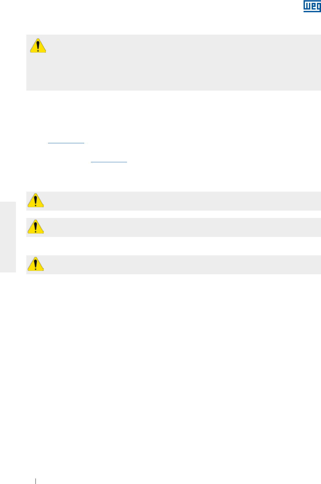
www.weg.net
Manual of Electric Motors62
ENGLISH
2. INITIAL RECOMMENDATIONS
For practical reasons, it is not possible to include in this Manual detailed information that covers all construction
variables nor covering all possible assembly, operation or maintenance alternatives.
This Manual contains only the required information that allows qualified and trained personnel to carry out their
services. The product images are shown for illustrative purpose only.
For Smoke Extraction Motors, please refer to the additional instruction manual 50026367 available on the
website www.weg.net.
For brake motors, please refer to the information contained in WEG 50006742 / 50021973 brake motor manual
available on the website www.weg.net.
For information about permissible radial and axial shaft loads, please check the product technical catalogue.
Electric motors have energized circuits, exposed rotating parts and hot surfaces that may cause serious
injury to people during normal operation. Therefore, it is recommended that transportation, storage,
installation, operation and maintenance services are always performed by qualified personnel.
Also the applicable procedures and relevant standards of the country where the machine will be installed must
be considered.
Noncompliance with the recommended procedures in this manual and other references on the WEG website
may cause severe personal injuries and/or substantial property damage and may void the product warranty.
The user is responsible for the correct definition of the installation environment and application
characteristics.
During the warranty period, all repair, overhaul and reclamation services must be carried out by WEG
authorized Service Centers to maintain validity of the warranty.
Warning about safety and warranty.
2.2. RECEIVING INSPECTION
All motors are tested during the manufacturing process.
The motor must be checked when received for any damage that may have occurred during the transportation.
All damages must be reported in writing to the transportation company, to the insurance company and to
WEG. Failure to comply with such procedures will void the product warranty.
You must inspect the product:
g Check if nameplate data complies with the purchase order;
g Remove the shaft locking device (if any) and rotate the shaft by hand to ensure that it rotates freely;
g Check that the motor has not been exposed to excessive dust and moisture during the transportation.
Do not remove the protective grease from the shaft, or the plugs from the cable entries. These protections must
remain in place until the installation has been completed.
2.1. WARNING SYMBOL
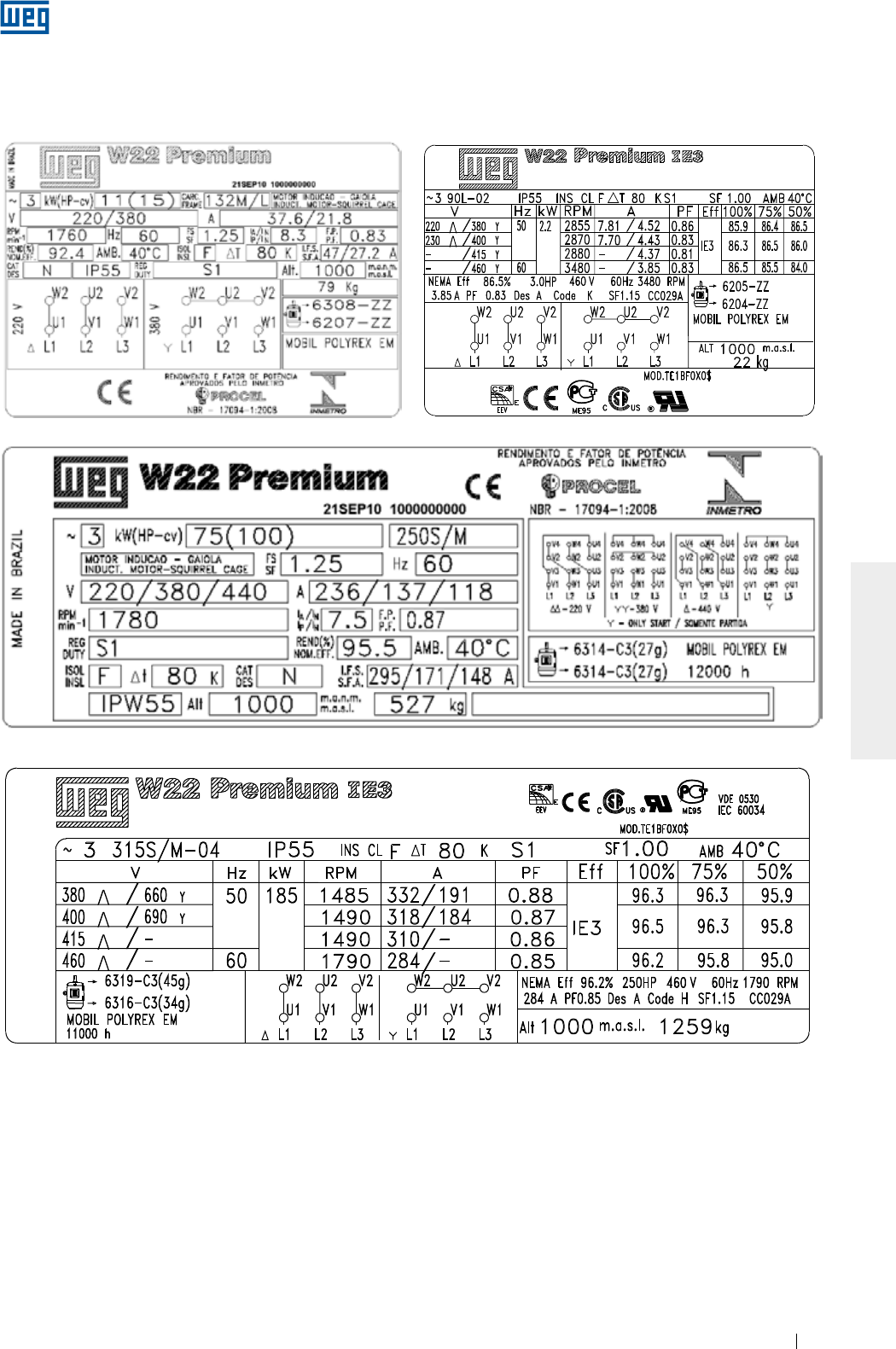
www.weg.net
Manual of Electric Motors 63
ENGLISH
2.3. NAMEPLATES
The nameplate contains information that describes the construction characteristics and the performance of the
motor. Figure 2.1 and Figure 2.2 show nameplate layout examples.
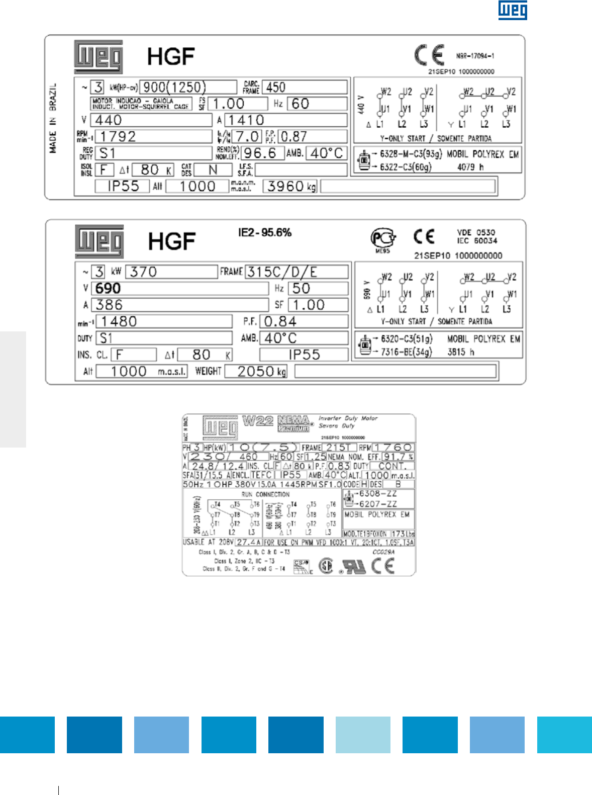
www.weg.net
Manual of Electric Motors64
ENGLISH
Figure 2.1 - IEC motor nameplate
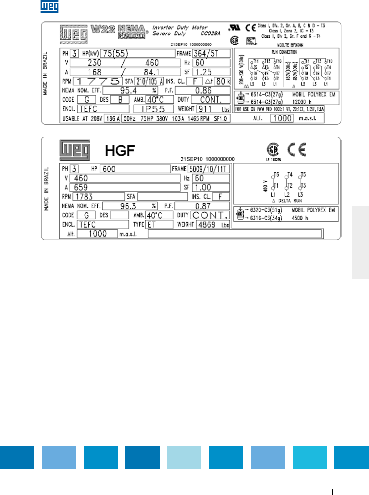
www.weg.net
Manual of Electric Motors 65
ENGLISH
Figure 2.2 - NEMA motor nameplate
www.weg.net
Manual of Electric Motors66
ENGLISH
3. SAFETY INSTRUCTIONS
The motor must be disconnected from the power supply and be completely stopped before conducting
any installation or maintenance procedures. Additional measures should be taken to avoid accidental
motor starting.
Professionals working with electrical installations, either in the assembly, operation or maintenance,
should use proper tools and be instructed on the application of standards and safety requirements,
including the use of Personal Protective Equipment (PPE) that must be carefully observed in order to
reduce risk of personal injury during these services.
Electric motors have energized circuits, exposed rotating parts and hot surfaces that may cause serious
injury to people during normal operation. It is recommended that transportation, storage, installation,
operation and maintenance services are always performed by qualified personnel.
Always follow the safety, installation, maintenance and inspection instructions in accordance with the applicable
standards in each country.
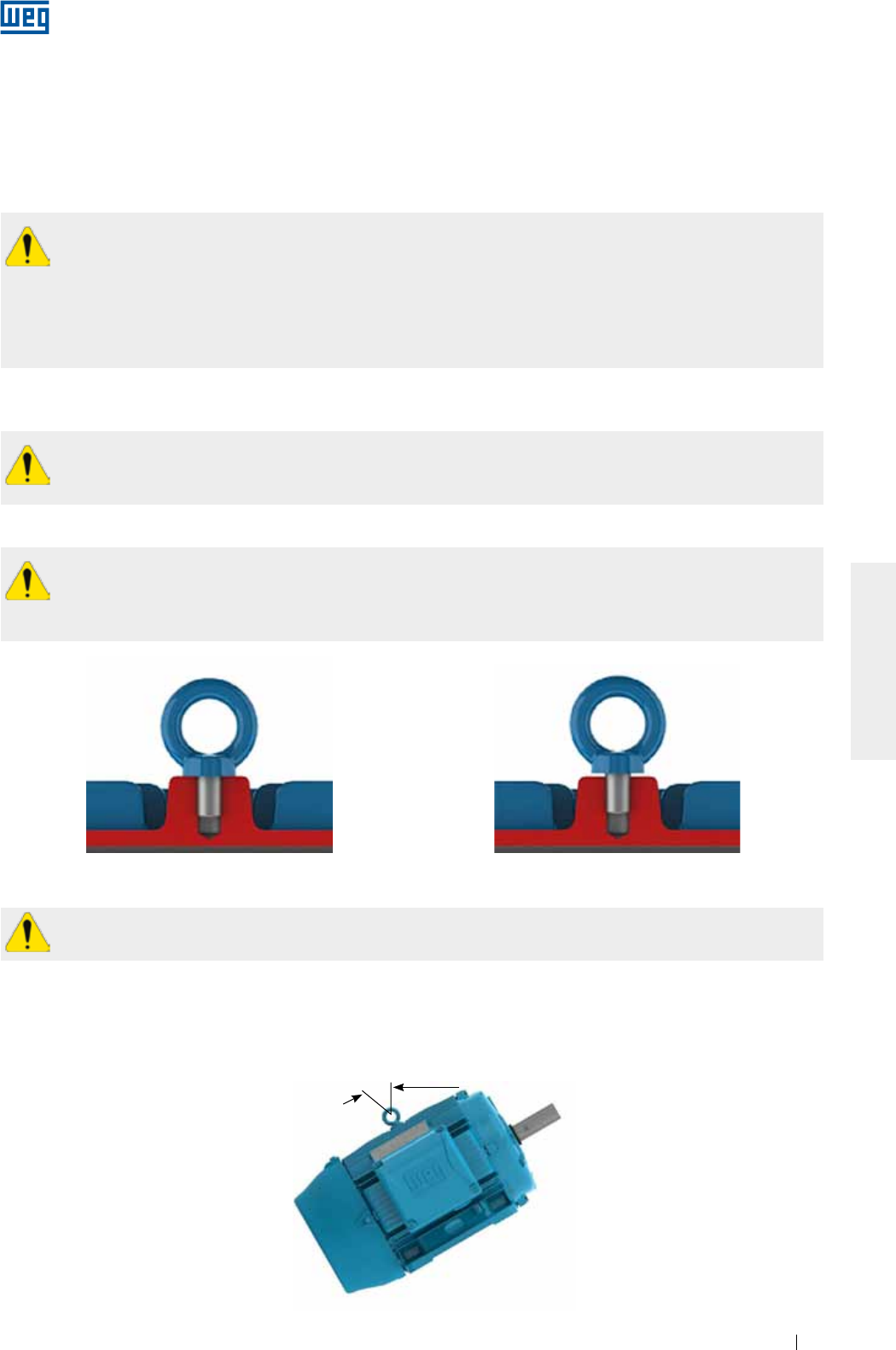
www.weg.net
Manual of Electric Motors 67
ENGLISH
Figure 4.1 - Correct tightening of the eyebolt Figure 4.2 - Incorrect tightening of
the eyebolt
4. HANDLING AND TRANSPORT
Eyebolts provided on the frame are designed for lifting the machine only. Do not use these eyebolts for
lifting the motor with coupled equipment such as bases, pulleys, pumps, reducers, etc..
Never use damaged, bent or cracked eyebolts. Always check the eyebolt condition before lifting the motor.
Eyebolts mounted on components, such as on end shields, forced ventilation kits, etc. must be used for lifting
these components only. Do not use them for lifting the complete machine set.
To move or transport motors with cylindrical roller bearings or angular contact ball bearings, use always
the shaft locking device provided with the motor.
All HGF motors, regardless of bearing type, must be transported with shaft locking device fitted.
Before lifting the motor ensure that all eyebolts are tightened properly and the eyebolt shoulders are in
contact with the base to be lifted, as shown in Figure 4.1. Figure 4.2 shows an incorrect tightening of the
eyebolt.
Ensure that lifting machine has the required lifting capacity for the weight indicated on the motor nameplate.
The center-of-gravity may change depending on motor design and accessories. During the lifting
procedures the maximum allowed angle of inclination should never be exceeded as specified below.
Individually packaged motors should never be lifted by the shaft or by the packaging. They must be lifted only by
means of the eyebolts, when supplied. Use always suitable lifting devices to lift the motor. Eyebolts on the frame
are designed for lifting the machine weight only as indicated on the motor nameplate. Motors supplied on pallets
must be lifted by the pallet base with lifting devices fully supporting the motor weight.
The package should never be dropped. Handle it carefully to avoid bearing damage.
Handle the motor carefully without sudden impacts to avoid bearing damage and prevent excessive mechanical
stresses on the eyebolts resulting in its rupture.
4.1. LIFTING
4.1.1. Horizontal motors with one eyebolt
For horizontal motors fitted with only one eyebolt, the maximum allowed angle-of-inclination during the lifting
process should not exceed 30º in relation to the vertical axis, as shown in Figure 4.3.
30° Max.
Figure 4.3 - Maximum allowed angle-of-inclination for motor with one eyebolt
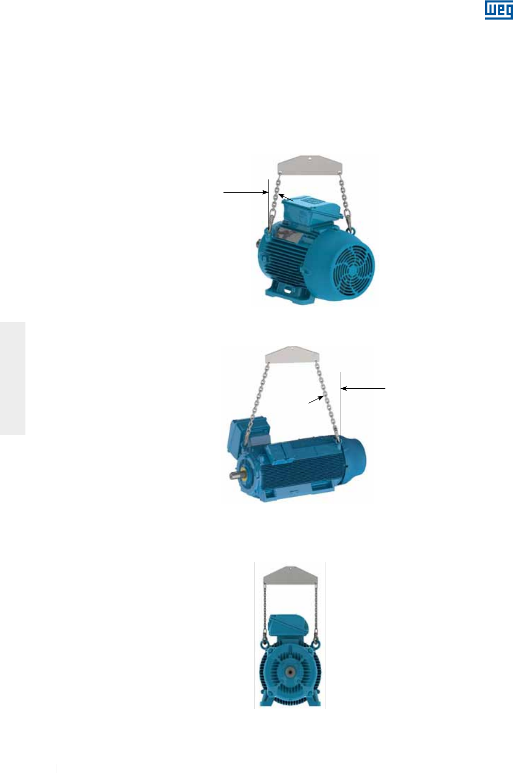
www.weg.net
Manual of Electric Motors68
ENGLISH
4.1.2. Horizontal motor with two eyebolts
When motors are fitted with two or more eyebolts, all supplied eyebolts must be used simultaneously for the
lifting procedure.
There are two possible eyebolt arrangements (vertical and inclined), as shown below:
g For motors with vertical lifting eyebolts, as shown in Figure 4.4, the maximum allowed lifting angle should not
exceed 45° in relation to the vertical axis. We recommend to use a spreader bar for maintaining the lifting
elements (chain or rope) in vertical position and thus preventing damage to the motor surface;
45° Max.
Figure 4.4 - Maximum resulting angle for motors with two or more lifting eyebolts
Figure 4.5 - Maximum resulting angle for horizontal HGF motors
Figure 4.6 - Use of a spreader bar for lifting
g For HGF motors, as shown in Figure 4.5, the maximum resulting angle should not exceed 30° in relation to the
vertical axis;
g For motors fitted with inclined eyebolts, as shown in Figure 4.6, the use of a spreader bar is required for
maintaining the lifting elements (chain or rope) in vertical position and thus preventing damage to the motor
surface.
30° Max.
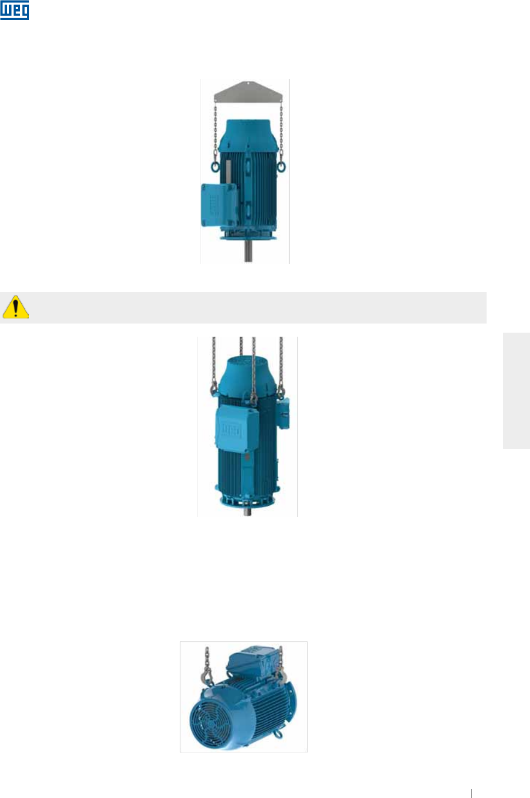
www.weg.net
Manual of Electric Motors 69
ENGLISH
4.1.3. Vertical motors
For vertical mounted motors, as shown in Figure 4.7, the use of a spreader bar is required for maintaining the
lifting element (chain or rope) in vertical position and thus preventing damage to the motor surface.
4.1.3.1. Procedures to place W22 motors in the vertical position
For safety reasons during the transport, vertical mounted Motors are usually packed and supplied in horizontal
position.
To place W22 motors fitted with eyebolts (see Figure 4.6), to the vertical position, proceed as follows:
1. Ensure that the eyebolts are tightened properly, as shown in Figure 4.1;
2. Remove the motor from the packaging, using the top mounted eyebolts, as shown in Figure 4.9;
Figure 4.7 - Lifting of vertical mounted motors
Figure 4.8 - Lifting of HGF motors
Figure 4.9 - Removing the motor from the packaging
Always use the eyebolts mounted on the top side of the motor, diametrically opposite, considering the
mounting position. See Figure 4.8.
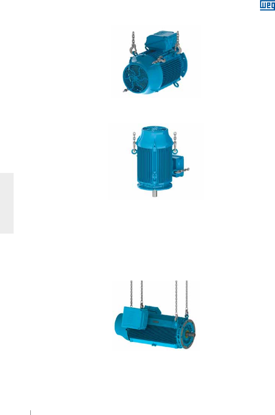
www.weg.net
Manual of Electric Motors70
ENGLISH
3. Install a second pair of eyebolts, as shown in Figure 4.10;
4. Reduce the load on the first pair of eyebolts to start the motor rotation, as shown in Figure 4.11. This
procedure must be carried out slowly and carefully.
These procedures will help you to move motors designed for vertical mounting. These procedures are also
used to place the motor from the horizontal position into the vertical position and vertical to horizontal.
Figure 4.10 - Installation of the second pair of eyebolts
Figure 4.11 - End result: motor placed in vertical position
Figure 4.12 - Lifting HGF motor with two hoists
4.1.3.2. Procedures to place HGF motors in the vertical position
HGF motors are fitted with eight lifting points: four at drive end and four at non-drive end. The HGF motors are
usually transported in horizontal position, however for the installation they must be placed in the vertical
position.
To place an HGF motor in the vertical position, proceed as follows:
1. Lift the motor by using the four lateral eyebolts and two hoists, see Figure 4.12;
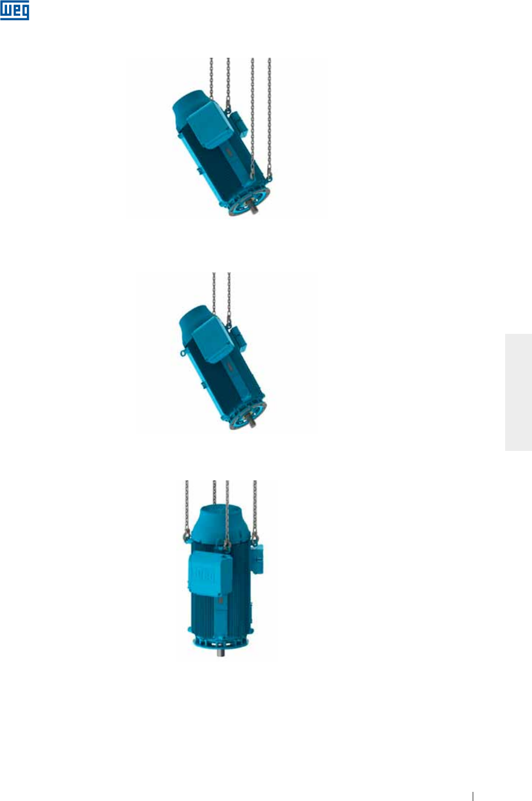
www.weg.net
Manual of Electric Motors 71
ENGLISH
2. Lower the hoist fixed to motor drive end while lifting the hoist fixed to motor non-drive end until the motor
reaches its equilibrium, see Figure 4.13;
3. Remove the hoist hooks from the drive end eyebolts and rotate the motor 180° to fix the removed hooks into
the two eyebolts at the motor non-drive end, see Figure 4.14;
4. Fix the removed hoist hooks in the other two eyebolts at the non-drive end and lift the motor until the vertical
position is reached, see Figure 4.15.
These procedures will help you to move motors designed for vertical mounting. These procedures are also
used to place the motor from the horizontal position into the vertical position and vertical to horizontal.
Figure 4.13 - Placing HGF motor in vertical position
Figure 4.14 - Lifting HGF motors by the eyebolts at the non-drive end
Figure 4.15 - HGF motor in the vertical position
4.2 Procedures to place W22 vertical mount motors in horizontal position
To place W22 vertical mount motor in horizontal position, proceed as follows:
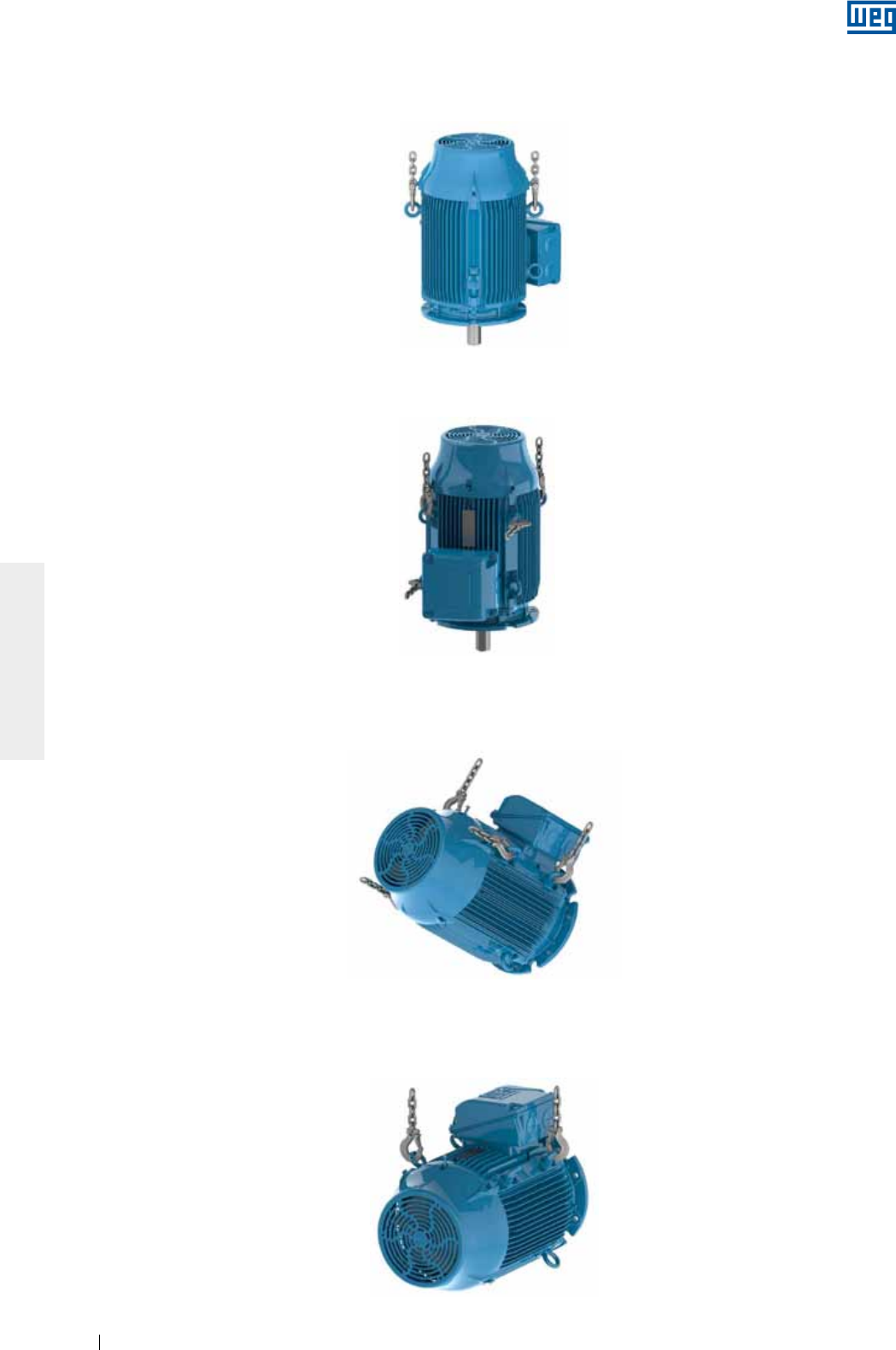
www.weg.net
Manual of Electric Motors72
ENGLISH
3. Install the second pair of eyebolts, as shown in Figure 4.17;
4. Reduce the load on the first pair of eyebolts for rotating the motor, as shown in Figure 4.18. This procedure
must be carried out slowly and carefully;
5. Remove the first pair of eyebolts, as shown in Figure 4.19.
Figure 4.16 - Install the first pair of eyebolts
Figure 4.17 - Install the second pair of eyebolts
Figure 4.18 - Motor is being rotated to horizontal position
Figure 4.19 - Final result: motor placed in horizontal position
1. Ensure that all eyebolts are tightened properly, as shown in Figure 4.1;
2. Install the first pair of eyebolts and lift the motor as shown in Figure 4.16;
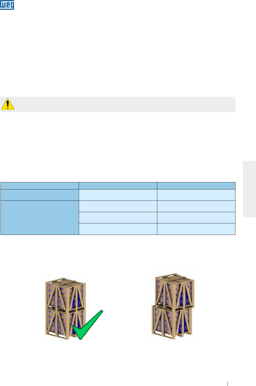
www.weg.net
Manual of Electric Motors 73
ENGLISH
5. STORAGE
If the motor is not installed immediately, it must be stored in a dry and clean environment, with relative humidity
not exceeding 60%, with an ambient temperature between 5 ºC and 40 ºC, without sudden temperature
changes, free of dust, vibrations, gases or corrosive agents. The motor must be stored in horizontal position,
unless specifically designed for vertical operation, without placing objects on it. Do not remove the protection
grease from shaft end to prevent rust.
If the motor are fitted with space heaters, they must always be turned on during the storage period or when the
installed motor is out of operation. Space heaters will prevent water condensation inside the motor and keep
the winding insulation resistance within acceptable levels. Store the motor in such position that the condensed
water can be easily drained. If fitted, remove pulleys or couplings from the shaft end (more information are given
on item 6).
5.1. EXPOSED MACHINED SURFACES
All exposed machined surfaces (like shaft end and flange) are factory-protected with temporary rust inhibitor. A
protective film must be reapplied periodically (at least every six months), or when it has been removed and/or
damaged.
5.2. STORAGE
The stacking height of the motor packaging during the storage period should not exceed 5 m, always
considering the criteria indicated in Table 5.1:
Notes:
1) Never stack larger packaging onto smaller packaging;
2) Align the packaging correctly (see Figure 5.1 and Figure 5.2);
The space heaters should never be energized when the motor is in operation.
Table 5.1 - Max. recommended stacking height
Packaging type Frame sizes Maximum stacking quantity
Cardboard box IEC 63 to 132
NEMA 143 to 215
Indicated on the top side of
the cardboard box
Wood crate
IEC 63 to 315
NEMA 48 to 504/5 06
IEC 355
NEMA 586/7 and 588/9 03
HGF IEC 315 to 630
HGF NEMA 5000 to 9600 Indicated on the packaging
X
Figure 5.1 - Correct stacking Figure 5.2 - Incorrect stacking
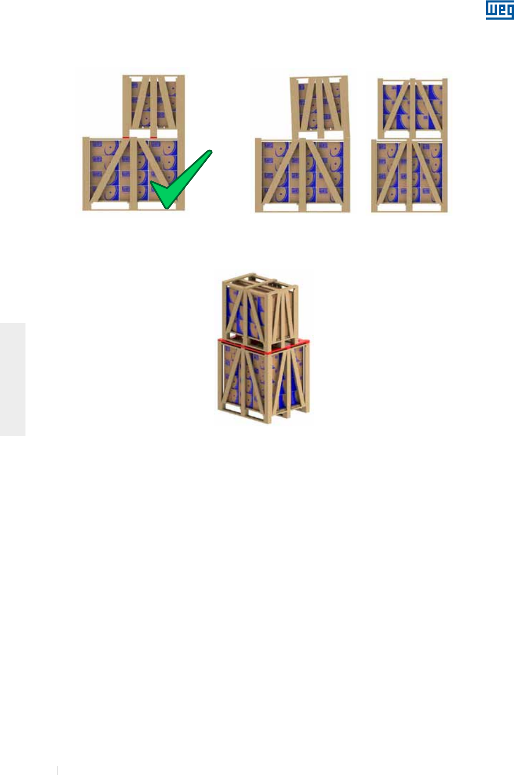
www.weg.net
Manual of Electric Motors74
ENGLISH
5.3 BEARINGS
5.3.1 Grease lubricated bearings
We recommend rotating the motor shaft at least once a month (by hand, at least five revolutions, stopping the
shaft at a different position from the original one). If the motor is fitted with shaft locking device, remove it before
rotating the shaft and install it again before performing any handling procedure. Vertical motors may be stored
in the vertical or in horizontal position. If motors with open bearings are stored longer than six months, the
bearings must be relubricated according to item 8.2 before commissioning of the motor.
If the motor is stored for longer than 2 years, the bearings must be replaced or removed, washed, inspected
and relubricated according to item 8.2.
5.3.2 Oil lubricated bearings
The motor must be stored in its original operating position and with oil in the bearings. Correct oil level must be
ensured. It should be in the center of the sight glass.
During the storage period, remove the shaft locking device and rotate the shaft by hand every month, at least
five revolutions, thus achieving an even oil distribution inside the bearing and maintaining the bearing in good
operating conditions. Reinstall the shaft locking device every time the motor has to be moved.
If the motor is stored for a period of over six months, the bearings must be relubricated according to Item 8.2
before starting the operation. If the motor is stored for a period of over two years, the bearings must be
replaced or removed, washed according to manufacturer instructions, checked and relubricated according to
Item 8.2. The oil of vertical mounted motors that are transported in horizontal position is removed to prevent oils
leaks during the transport. These motors must be stored in vertical position after receiving and the bearing
must be lubricated.
3) The feet of the crates above should always be supported by suitable wood battens (Figure 5.3) and never stand on the steel tape or
without support (Figure 5.4);
4) When stacking smaller crates onto longer crates, always ensure that suitable wooden supports are provided to withstand the weight
(see Figure 5.5). This condition usually occurs with motor packaging above IEC 225S/M (NEMA 364/5T) frame sizes.
Figure 5.5 - Use of additional battens for stacking
Figure 5.3 - Correct stacking Figure 5.4 - Incorrect stacking
X X
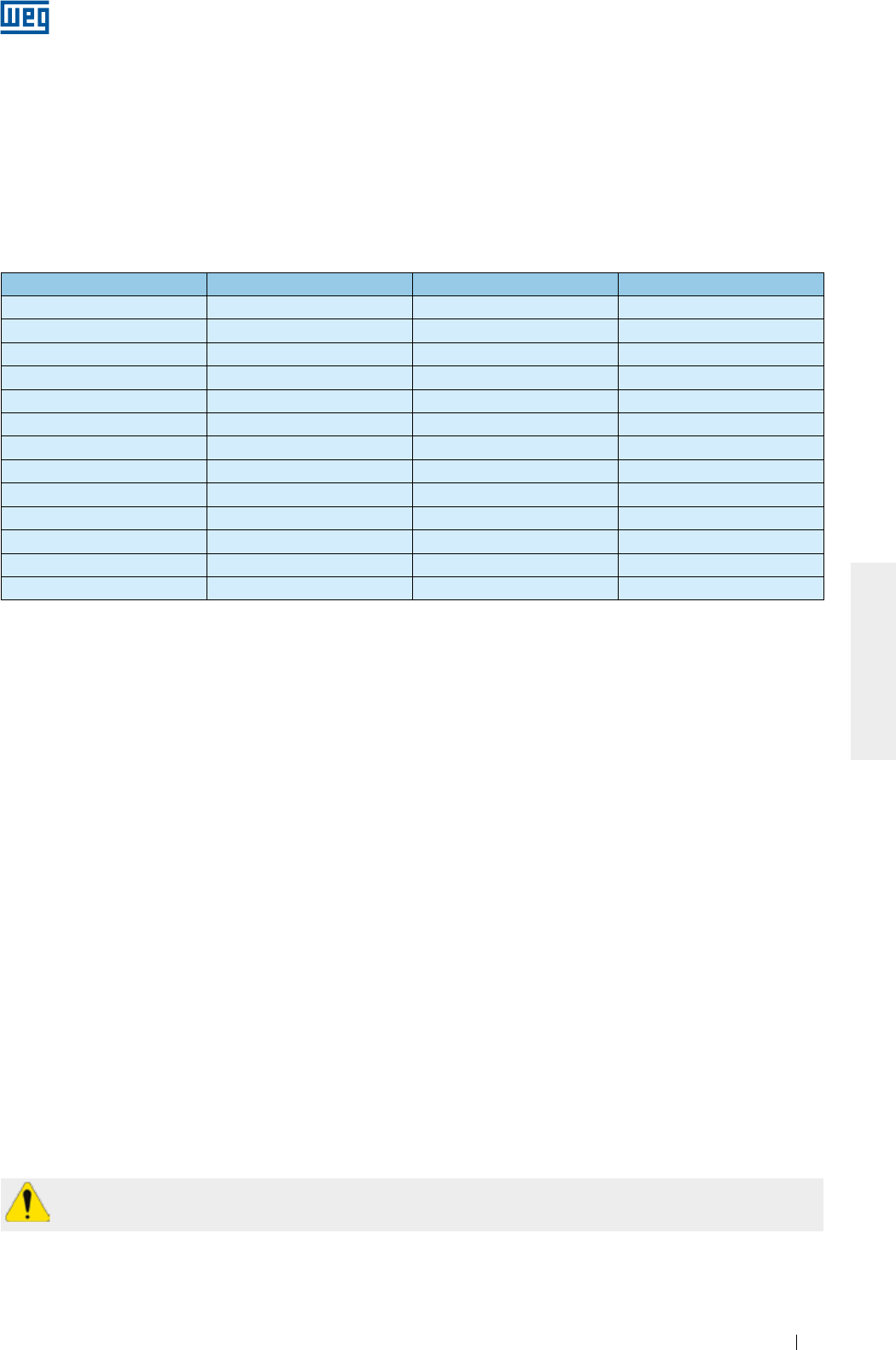
www.weg.net
Manual of Electric Motors 75
ENGLISH
5.3.3 Oil Mist lubricated bearings
The motor must be stored in horizontal position. Lubricate the bearings with ISO VG 68 mineral oil in the
amount indicated in the Table 5.2 (this is also valid for bearings with equivalent dimensions). After filling with oil,
rotate the shaft by hand, at least five revolutions)
During the storage period, remove the shaft locking device (if any) and rotate the shaft by hand every week, at
least five revolutions, stopping it at a different position from the original one. Reinstall the shaft locking device
every time the motor has to be moved. If the motor is stored for a period of over two years, the bearings must
be replaced or removed, washed according to manufacturer instructions, checked and relubricated according
to item 8.2.
5.3.4 Sleeve bearing
The motor must be stored in its original operating position and with oil in the bearings. Correct oil level must be
ensured. It should be in the middle of the sight glass. During the storage period, remove the shaft locking
device and rotate the shaft by hand every month, at least five revolutions, and at 30 rpm, thus achieving an
even oil distribution inside the bearing and maintaining the bearing in good operating conditions. Reinstall the
shaft locking device every time the motor has to be moved.
If the motor is stored for a period of over six months, the bearings must be relubricated according to the Item
8.2 before starting the operation.
If the motor is stored for a period longer than the oil change interval, or if it is not possible to rotate the motor
shaft by hand, the oil must be drained and a corrosion protection and dehumidifiers must be applied.
The oil must always be removed when the motor has to be handled. If the oil mist system is not operating after
installation, fill the bearings with oil to prevent bearing rusting. During the storage period, rotate the shaft by
hand, at least five revolutions, stopping it at a different position from the original one. Before starting the motor,
all bearing protection oil must be drained from the bearing and the oil mist system must be switched ON.
Table 5.2 - Amount of oil per bearing
Bearing size Amount of oil (ml) Bearing size Amount of oil (ml)
6201 15 6309 65
6202 15 6311 90
6203 15 6312 105
6204 25 6314 150
6205 25 6315 200
6206 35 6316 250
6207 35 6317 300
6208 40 6319 350
6209 40 6320 400
6211 45 6322 550
6212 50 6324 600
6307 45 6326 650
6308 55 6328 700
5.4. INSULATION RESISTANCE
We recommend measuring the winding insulation resistance at regular intervals to follow-up and evaluate its
electrical operating conditions. If any reduction in the insulation resistance values are recorded, the storage
conditions should be evaluated and corrected, where necessary.
5.4.1. Insulation resistance measurement
We recommend measuring the winding insulation resistance at regular intervals to follow-up and evaluate its
electrical operating conditions. If any reduction in the insulation resistance values are recorded, the storage
conditions should be evaluated and corrected, where necessary.
The insulation resistance must be measured in a safe environment.
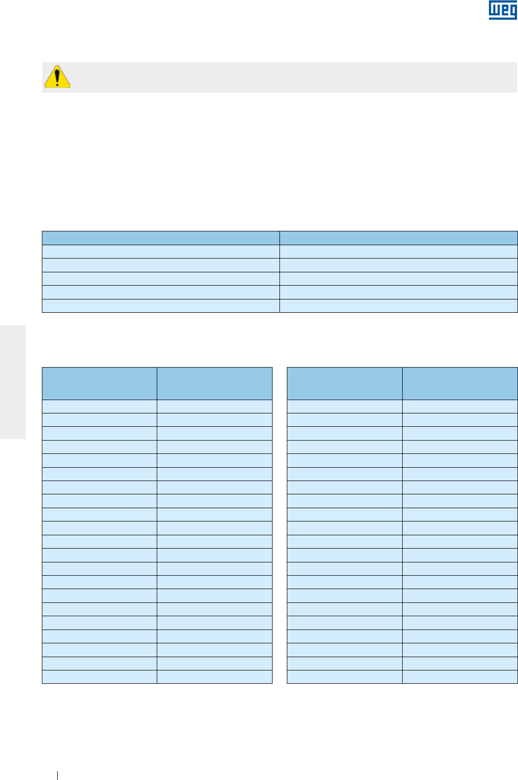
www.weg.net
Manual of Electric Motors76
ENGLISH
The insulation resistance must be measured with a megohmmeter. The machine must be in cold state and
disconnected from the power supply.
The reading of the insulation resistance must be corrected to 40 °C as shown in the Table 5.4.
It is recommended to insulate and test each phase separately. This procedure allows the comparison of the
insulation resistance between each phase. During the test of one phase, the other phases must be grounded.
The test of all phases simultaneously evaluates the insulation resistance to ground only but does not evaluate
the insulation resistance between the phases.
The power supply cables, switches, capacitors and other external devices connected to the motor may
considerably influence the insulation resistance measurement. Thus all external devices must be disconnected
and grounded during the insulation resistance measurement.
Measure the insulation resistance one minute after the voltage has been applied to the winding. The applied
voltage should be as shown in Table 5.3.
Table 5.3 - Voltage for the insulation resistance
Table 5.4 - Correction factor for the insulation resistance corrected to 40 °C
To prevent the risk of an electrical shock, ground the terminals before and after each measurement.
Ground the capacitor (if any) to ensure that it is fully discharged before the measurement is taken.
Winding rated voltage (V) Testing voltage for measuring the insulation resistance (V)
< 1000 500
1000 - 2500 500 - 1000
2501 - 5000 1000 - 2500
5001 - 12000 2500 - 5000
> 12000 5000 - 10000
Measuring temperature
of the insulation
resistance (°C)
Correction factor of the
insulation resistance
corrected to 40 °C
10 0.125
11 0.134
12 0.144
13 0.154
14 0.165
15 0.177
16 0.189
17 0.203
18 0.218
19 0.233
20 0.250
21 0.268
22 0.287
23 0.308
24 0.330
25 0.354
26 0.379
27 0.406
28 0.435
29 0.467
30 0.500
Measuring temperature of
the insulation resistance
(°C)
Correction factor of the
insulation resistance
corrected to 40 °C
30 0.500
31 0.536
32 0.574
33 0.616
34 0.660
35 0.707
36 0.758
37 0.812
38 0.871
39 0.933
40 1.000
41 1.072
42 1.149
43 1.231
44 1.320
45 1.414
46 1.516
47 1.625
48 1.741
49 1.866
50 2.000
www.weg.net
Manual of Electric Motors 77
ENGLISH
The motor insulation condition must be evaluated by comparing the measured value with the values
indicated in Table 5.5 (corrected to 40 °C):
The values indicated in the table should be considered only as reference values. It is advisable to log all
measured values to provide a quick and easy overview on the machine insulation resistance.
If the insulation resistance is low, moisture may be present in the stator windings. In this case the motor
should be removed and transported to a WEG authorized Service Center for proper evaluation and repair
(This service is not covered by the warranty). To improve the insulation resistance through the drying
process, see section 8.4.
Table 5.5 - Evaluation of the insulation system
Limit value for rated voltage
up to 1.1 kV (M)
Limit value for rated voltage
above 1.1 kV (M) Situation
Up to 5 Up to 100 Dangerous. The motor can not
be operated in this condition
5 to 100 100 to 500 Regular
100 to 500 Higher than 500 Good
Higher than 500 Higher than 1000 Excellent
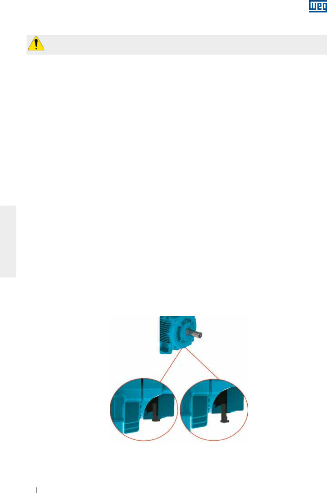
www.weg.net
Manual of Electric Motors78
ENGLISH
Figure 6.1 - Detail of the rubber drain plug mounted in closed and open position
6. INSTALLATION
Check some aspects before proceeding with the installation:
1. Insulation resistance: must be within the acceptable limits. See item 5.4.
2. Bearings:
a. Rolling bearings: oxidized bearings must be replaced. If no oxidation is detected, lubricate the bearings as
described in Item 8.2. If the motor is stored for a period of over two years, the bearings must be replaced
before starting the motor;
b. Sleeve bearing: if sleeve bearing motors are stored longer than the recommended oil change interval, the
oil must be changed before machine starting. Don’t forget to remove the dehumidifiers when you drain the
oil from the motor and to fill it again with new oil before starting the machine. For more details, see item
8.2.
3. Operating conditions of the start capacitors: If single-phase motors are stored for a period of over two years,
it is recommended to change the start capacitors before motor starting since they lose their operating
characteristics.
4. Terminal box:
a. the inside of the terminal box must be clean and dry;
b. the contacts must be correctly connected and corrosion free. See 6.9 and 6.10;
c. the cable entries must be correctly sealed and the terminal box cover properly mounted in order to ensure
the degree of protection indicated on the motor nameplate.
5. Cooling: the cooling fins, air inlet and outlet openings must be clean and unobstructed. The distance
between the air inlet openings and the wall should not be shorter than ¼ (one quarter) of the diameter of the
air inlet. Ensure sufficient space to perform the cleaning services. See item 7.
6. Coupling: remove the shaft locking device (where fitted) and the corrosion protection grease from the shaft
end and flange just before installing the motor. See item 6.4.
7. Drain hole: the motor must always be positioned so the drain hole is at the lowest position (If there is any
indication arrow on the drain, the drain must be so installed that the arrow points downwards).
Motors supplied with rubber drain plugs leave the factory in the closed position and must be opened
periodically to allow the exit of condensed water. For environments with high water condensation levels and
motor with degree of protection IP55, the drain plugs can be mounted in open position (see Figure 6.1).
For motors with degree of protection IP56, IP65 or IP66, the drain plugs must remain at closed position (see
Figure 6.1), being opened only during the motor maintenance procedures.
The drain system of motors with Oil Mist lubrication system must be connected to a specific collection
system (see Figure 6.12).
The insulation resistance must be measured in a safe environment.
Closed position Open position
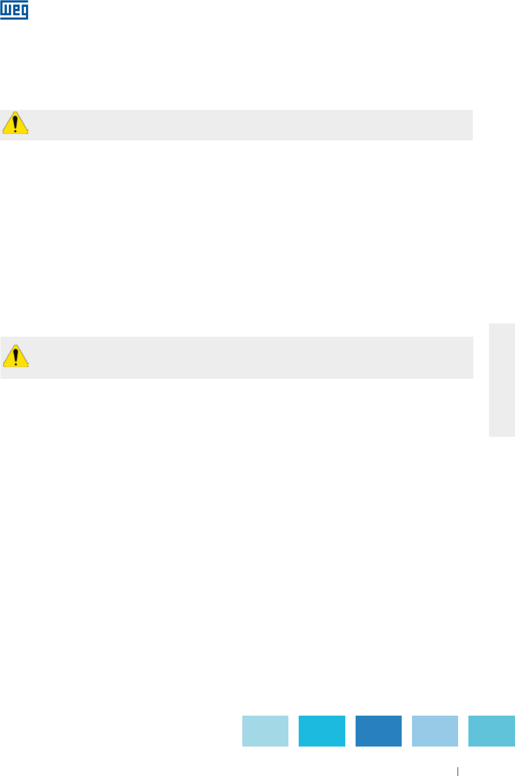
www.weg.net
Manual of Electric Motors 79
ENGLISH
8.Additional recommendations:
a. Check the direction of motor rotation, starting the motor at no-load before coupling it to the load;
b. Vertical mounted motors with shaft end down must be fitted with drip cover to protect them from liquids
or solids that may drop onto the motors;
c. Vertical mounted motors with shaft end up must be fitted with water slinger ring to prevent water
penetration inside the motor.
Remove or fix the shaft key before starting the motor.
Please consider for the foundation dimensioning all stresses that are generated during the operation of
the driven load.
The user is responsible for the foundation designing and construction.
6.1. FOUNDATIONS
The foundation is the structure, structural element, natural or prepared base, designed to withstand the
stresses produced by the installed equipment, ensuring safe and stable performance during operation. The
foundation design should consider the adjacent structures to avoid the influences of other installed equipment
and no vibration is transferred through the structure
The foundation must be flat and its selection and design must consider the following characteristics:
a) The features of the machine to be installed on the foundation, the driven loads, application, maximum
allowed deformations and vibration levels (for instance, motors with reduced vibration levels, foot flatness,
flange concentricity, axial and radial loads, etc. lower than the values specified for standard motors).
b) Adjacent buildings, conservation status, maximum applied load estimation, type of foundation and fixation
and vibrations transmitted by theses constructions.
If the motor is supplied with leveling/alignment bolts, this must be considered in the base design.
The foundation stresses can be calculated by using the following equations (see Figure 6.2):
F1 = 0,5 * g * m - (4 * Tb / A)
F2 = 0,5 * g * m + (4 * Tb / A)
Where:
F1 and F2 = lateral stresses (N);
g = gravitational acceleration (9,8 m/s2);
m = motor weight (kg);
Tb = breakdown torque (Nm);
A = distance between centerlines of mounting holes in feet or base of the machine (end view) (m).
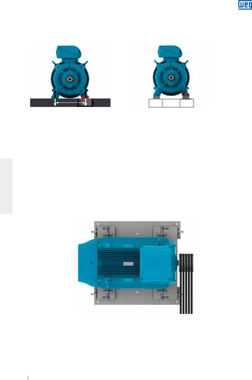
www.weg.net
Manual of Electric Motors80
ENGLISH
The motors may be mounted on:
g Concrete bases: are most used for large-size motors (see Figure 6.2);
g Metallic bases: are generally used for small-size motors (see Figure 6.3).
The metallic and concrete bases may be fitted with sliding system. These types of foundations are generally
used where the power transmission is achieved by belts and pulleys. This power transmission system is easier
to assemble/disassemble and allows the belt tension adjustment. Other important aspect of this foundation
type is the location of the base locking screws that must be diagonally opposite. The rail nearest the drive
pulley is placed in such a way that the positioning bolt is between the motor and the driven machine. The other
rail must be placed with the bolt on the opposite side (diagonally opposite), as shown in Figure 6.4 .
To facilitate assembly, the bases may have the following features:
g Shoulders and/or recesses;
g Anchor bolts with loose plates;
g Bolts cast in the concrete;
g Leveling screws;
g Positioning screws;
g Steel & cast iron blocks, plates with flat surfaces.
Figure 6.4 - Motor installed on sliding base
After completing the installation, it is recommended that all exposed machined surfaces are coated with
suitable rust inhibitor.
Figure 6.2 - Motor installed on concrete base Figure 6.3 - Motor installed on metallic base
A
F1F1
F2F2
A
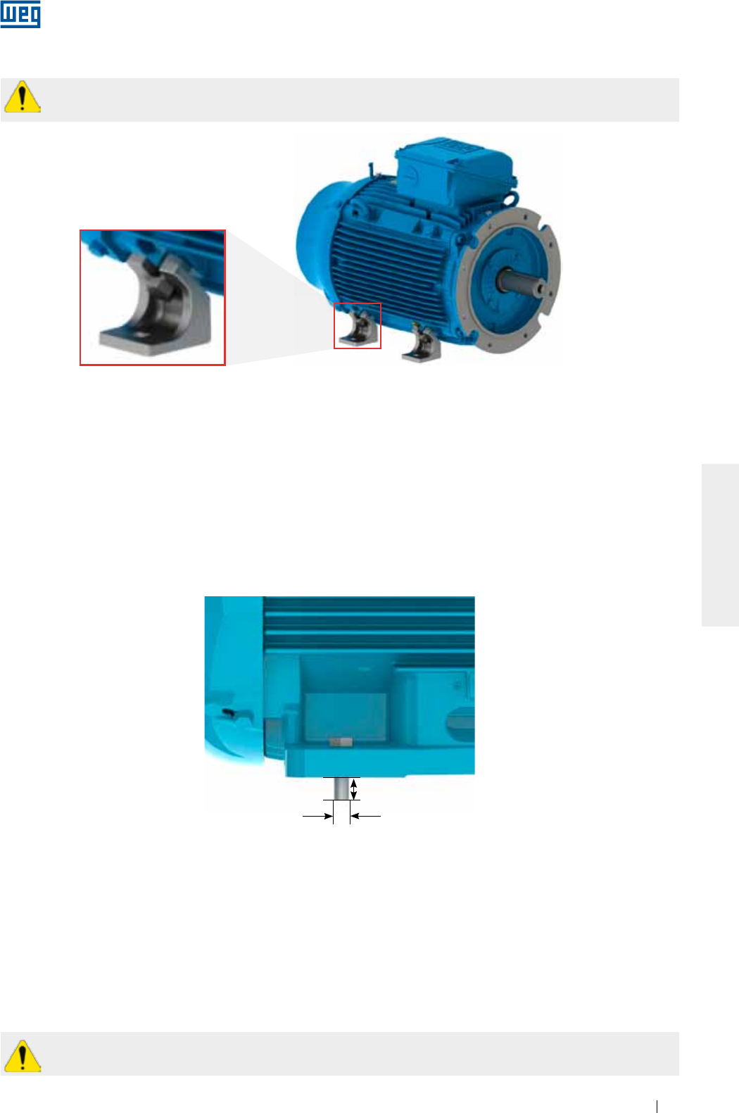
www.weg.net
Manual of Electric Motors 81
ENGLISH
6.2.1. Foot mounted motors
The drawings of the mounting hole dimensions for NEMA or IEC motors can be checked in the respective
technical catalogue.
The motor must be correctly aligned and leveled with the driven machine. Incorrect alignment and leveling may
result in bearing damage, generate excessive vibration and even shaft distortion/breakage.
For more details, see section 6.3 and 6.6. The thread engagement length of the mounting bolt should be at
least 1.5 times the bolt diameter. This thread engagement length should be evaluated in more severe
applications and increased accordingly.
Figure 6.6 shows the mounting system of a foot mounted motor indicating the minimum required thread
engagement length.
Figure 6.6 - Mounting system of a foot mounted motor
L = 1.5 x D
D
6.2.2. Flange mounted motors
The drawings of the flange mounting dimensions, IEC and NEMA flanges, can be checked in the technical
catalogue.
The coupling of the driven equipment to the motor flange must be properly dimensioned to ensure the required
concentricity of the assembly.
Depending on the flange type, the mounting can be performed from the motor to the driven equipment flange
(flange FF (IEC) or D (NEMA)) or from the driven equipment flange to the motor (flange C (DIN or NEMA)).
For the mounting process from the driven equipment flange to the motor, you must consider the bolt length,
flange thickness and the thread depth of the motor flange.
If the motor flange has tapped through-holes, the length of the mounting bolts must not exceed the
tapped through-hole length of the motor flange, thus preventing damage to the winding head.
6.2. MOTOR MOUNTING
Footless motors supplied with transportation devices, according to Figure 6.5, must have their devices
removed before starting the motor installation.
Figure 6.5 - Detail of the transportation devices for footless motors
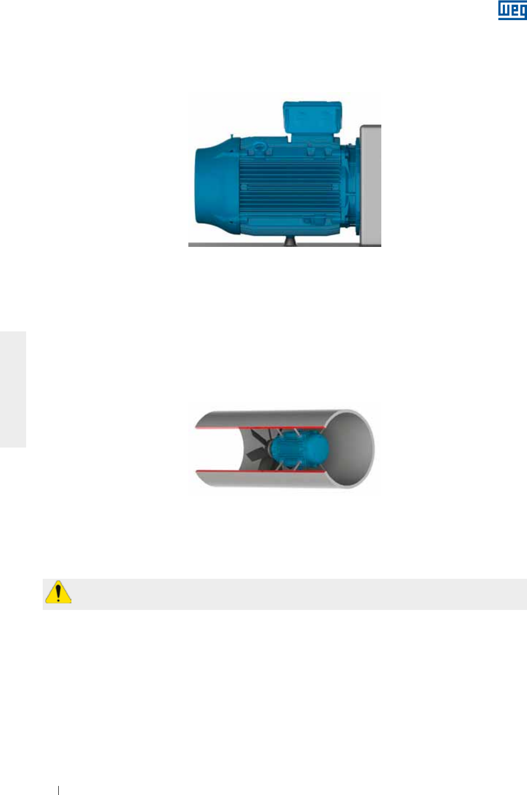
www.weg.net
Manual of Electric Motors82
ENGLISH
For flange mounting the thread engagement length of the mounting bolt should be at least 1.5 times the bolt
diameter. In severe applications, longer thread engagement length may be required.
In severe applications or if large motors are flange mounted, a foot or pad mounting may be required in addition
to the flange mounting (Figure 6.7). The motor must never be supported on its cooling fins.
6.2.3. Pad mounted motors
Typically, this method of mounting is used in axial fans. The motor is fixed by tapped holes in the frame. The
dimensions of these tapped holes can be checked in the respective product catalogue. The selection of the
motor mounting rods/bolts must consider the dimensions of the fan case, the installation base and the thread
depth in the motor frame.
The mounting rods and the fan case wall must be sufficiently stiff to prevent the transmission of excessive
vibration to the machine set (motor & fan). Figure 6.8 shows the pad mounting system.
Figure 6.7 - Mounting method of flange mounted motors with frame base support
Figure 6.8 - Mounting of the motor inside the cooling duct
Note:
When liquid (for example oil) is likely to come into contact with the shaft seal, please contact your local WEG representative.
The balance quality grade meets the applicable standards for each product line.
The maximum balancing deviation must be recorded in the installation report.
The transmission elements, such as pulleys, couplings, etc., must balanced with “half key” before they
are mounted on the motor shaft.
6.3. BALANCING
Unbalanced machines generate vibration which can result in damage to the motor. WEG motors are
dynamically balanced with “half key” and without load (uncoupled). Special balancing quality level must be
stated in the Purchase Order.
6.4. COUPLINGS
Couplings are used to transmit the torque from the motor shaft to the shaft of the driven machine. The following
aspects must be considered when couplings are installed:
g Use proper tools for coupling assembly & disassembly to avoid damages to the motor and bearings;
g Whenever possible, use flexible couplings, since they can absorb eventual residual misalignments during the
machine operation;
g The maximum loads and speed limits informed in the coupling and motor manufacturer catalogues cannot
be exceeded;
g Level and align the motor as specified in sections 6.5 and 6.6, respectively.
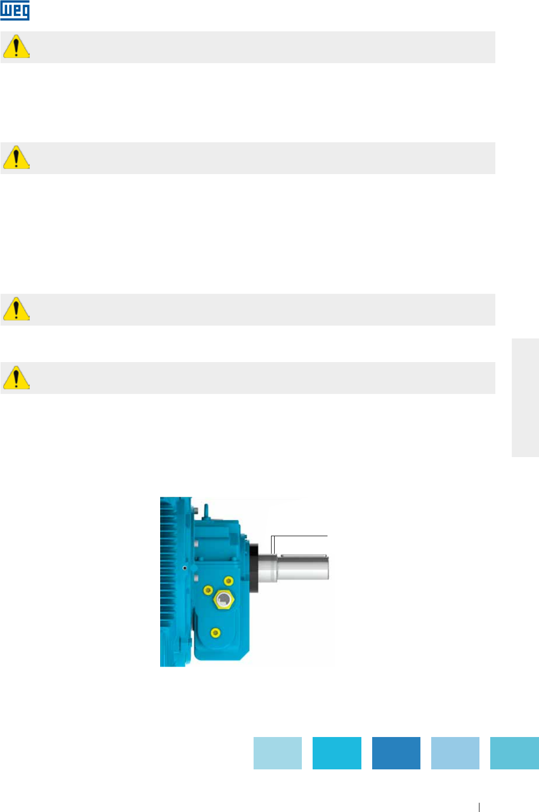
www.weg.net
Manual of Electric Motors 83
ENGLISH
Motors designed with sleeve bearings have 3 (three) marks on the shaft end. The center mark is the indication
of the magnetic center and the 2 (two) outside marks indicate the allowed limits of the rotor axial movement, as
shown in Figure 6.9.
The motor must be so coupled that during operation the arrow on the frame is placed over the central mark
indicating the rotor magnetic center. During start-up, or even during operation, the rotor may freely move
between the two outside marks when the driven machine exerts an axial load on the motor shaft. However,
under no circumstance, the motor can operate continuously with axial forces on the bearing.
6.4.1. Direct coupling
Direct coupling is characterized when the Motor shaft is directly coupled to the shaft of the driven machine
without transmission elements. Whenever possible, use direct coupling due to lower cost, less space required
for installation and more safety against accidents.
6.4.2. Gearbox coupling
Gearbox coupling is typically used where speed reduction is required.
Make sure that shafts are perfectly aligned and strictly parallel (in case of straight spur gears) and in the right
meshing angle (in case of bevel and helical gears).
6.4.3. Pulley and belt coupling
Pulleys and belts are used when speed increase or reduction between motor shaft and driven load is required.
6.4.4. Coupling of sleeve bearing motors
Remove or fix the shaft key firmly when the motor is operated without coupling in order to prevent
accidents.
Do not use roller bearings for direct coupling, unless sufficient radial load is expected.
Excessive belt tension will damage the bearings and cause unexpected accidents such as breakage of
the motor shaft.
Motors designed with sleeve bearings must be operated with direct coupling to the driven machine or a
gearbox. Pulley and belts can not be applied for sleeve bearing motors.
Axial clearance
Figure 6.9 - Axial clearance of motor designed with sleeve bearing
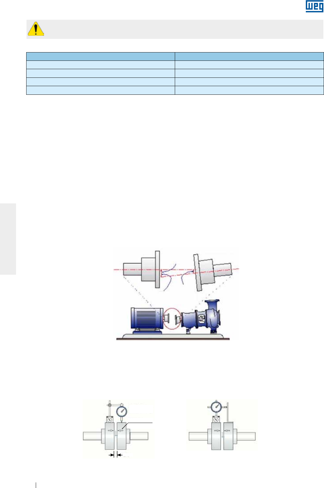
www.weg.net
Manual of Electric Motors84
ENGLISH
The sleeve bearings used by WEG were not designed to support axial load continuously.
Under no circumstance must the motor be operated continuously at its axial clearance limits.
Figure 6.10 - Typical misalignment condition
* For Motors in accordance with API 541, the total axial clearance is 12.7 mm
For coupling evaluation consider the maximum axial bearing clearance as shown in Table 6.1.
The axial clearance of the driven machine and coupling influence the maximum bearing clearance.
Table 6.1 - Clearance used for sleeve bearings
Bearing size Total axial clearance (mm)
9* 3 + 3 = 6
11* 4 + 4 = 8
14* 5 + 5 =10
18 7,5 + 7,5 = 15
6.5. LEVELING
The motor must be leveled to correct any deviations in flatness arising from the manufacturing process and the
material structure rearrangement. The leveling can be carried out by a leveling screw fixed on the motor foot or
on the flange or by means of thin compensation shims. After the leveling process, the leveling height between
the motor mounting base and the motor cannot exceed 0.1 mm.
If a metallic base is used to level the height of the motor shaft end and the shaft end of the driven machine, level
only the metallic base relating to the concrete base.
Record the maximum leveling deviations in the installation report.
6.6. ALIGNMENT
The correct alignment between the motor and the driven machine is one of the most important variables that
extends the useful service life of the motor. Incorrect coupling alignment generates high loads and vibrations
reducing the useful life of the bearings and even resulting in shaft breakages. Figure 6.10 illustrates the
misalignment between the motor and the driven machine.
Alignment procedures must be carried out using suitable tools and devices, such as dial gauge, laser alignment
instruments, etc.. The motor shaft must be aligned axially and radially with the driven machine shaft.
The maximum allowed eccentricity for a complete shaft turn should not exceed 0.03 mm, when alignment is
made with dial gauges, as shown in Figure 6.11. Ensure a gap between couplings to compensate the thermal
expansion between the shafts as specified by the coupling manufacturer.
Motor shaft Driven machine shaft
Max.
misalignment
Driven machine
offset (mm)
Motor
offset (mm)
Figure 6.11 - Alignment with dial gauge
Parallel alignment Angular alignment
GAP
Dial gauge
Line
Reference
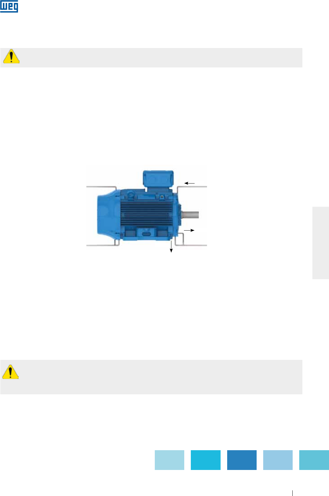
www.weg.net
Manual of Electric Motors 85
ENGLISH
If alignment is made by a laser instrument, please consider the instructions and recommendations provided by
the laser instrument manufacturer.
The alignment should be checked at ambient temperature with machine at operating temperature.
Pulley and belt couplings must be so aligned that the driver pulley center lies in the same plane of the driven
pulley center and the motor shaft and the shaft of the driven machine are perfectly parallel.
After completing the alignment procedures, ensure that mounting devices do not change the motor and
machine alignment and leveling resulting into machine damage during operation.
It is recommended to record the maximum alignment deviation in the Installation Report.
The coupling alignment must be checked periodically.
6.7. CONNECTION OF OIL LUBRICATED OR OIL MIST LUBRICATED MOTORS
When oil lubricated or oil mist lubricated motors are installed, connect the existing lubricant tubes (oil inlet and
oil outlet tubes and motor drain tube), as shown in Figure 6.12. The lubrication system must ensure continuous
oil flow through the bearings as specified by the manufacturer of the installed lubrication system.
Inlet
Drain
Outlet
Figure 6.12 - Oil supply and drain system of oil lubricated or oil mist lubricated motors
6.8. CONNECTION OF THE COOLING WATER SYSTEM
When water cooled motors are installed, connect the water inlet and outlet tubes to ensure proper motor
cooling. According to item 7.2, ensure correct cooling water flow rate and water temperature in the motor
cooling system.
6.9. ELECTRICAL CONNECTION
Consider the rated motor current, service factor, starting current, environmental and installation conditions,
maximum voltage drop, etc. to select appropriate power supply cables and switching and protection devices.
All motors must be installed with overload protection systems. Three-phase motors should be fitted with phase
fault protection systems.
Before connecting the motor, check if the power supply voltage and the frequency comply with the
motor nameplate data. All wiring must be made according to the connection diagram on the motor
nameplate. Please consider the connection diagrams in the Table 6.2 as reference value.
To prevent accidents, check if motor has been solidly grounded in accordance with the applicable standards.
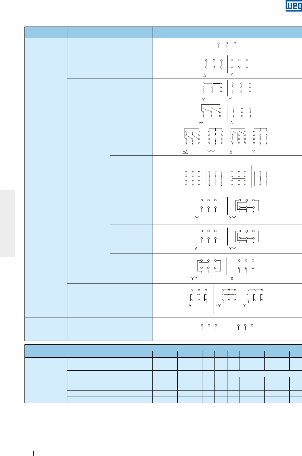
www.weg.net
Manual of Electric Motors86
ENGLISH
Configuration Quantity of leads Type of
connection Connection diagram
Single speed
3 -
L1 L2 L3
31 2
L2L1
1
6
L3
2 3
4 5
L2L1
1
6
L3
2 3
4 5
L3L2L1 L3L2L1
5
2
8
7
1
49
3
68
2
5
7
1
49
3
6
45 64
L1
7
1L3
98 32
L2
7
L1
1
65
3
9
L2 L3
2
8
78 9
L3L2
2L1
3
5
11 12
610
1
4
1
32 L3L2 L1
11
5
8
12 10
6
94
71
32 L3L2 L1
11
5
8
12 10
6
94
71
32 L3L2 L1
11
5
8
12 10
6
94
7
L2
4
L1 L2
1 2
6
L3 L1
3
5
L2L3 L1 L3 L1
RUNSTART
12 10
7 8
PART-WINDING
11
9
START
WYE-DELTA
L2 L3
RUN
3
5
9
11
8
4
2
10
1
6
7
12 1012 11
6 4 5
987 321 3
9
5
11
2
8
1
74
10
6
12
1 2
L2L1
6 4
3
L3 L1 L2
5
L3
LOW SPEED HIGH SPEED
LOW SPEED
L1 L3L2 L3
HIGH SPEED
L1 L2
31 2 1 2 3
LOW SPEED L1 L3L2
L3 HIGH SPEED
L1 L2
6
3
4
1
5
2
1 2 3
4 5 6
LOW SPEED
L1 L3L2 L3
HIGH SPEED
L1 L2
6
3
4
1
5
21 2 3
4 5 6
ONLY FOR
STARTING
6
54
L1 L2 L3
87
1 2 9
3
64 5
HIGH SPEED
L1 L2 L3
8
2
7
19
3
LOW SPEED
5
4
L1 L2
8
7
126
L3
9
3
ONLY FOR
STARTING
654
L1 L2 L3
87
1 2 9
3
64 5
HIGH SPEED
L1 L2 L3
8
2
7
19
3
LOW SPEED
5
4
L1 L2
8
7
126
L3
9
3
64 5 4 5 6
L1 L2 L3
31 2
L2L1
1
6
L3
2 3
4 5
L2L1
1
6
L3
2 3
4 5
L3L2L1 L3L2L1
5
2
8
7
1
49
3
68
2
5
7
1
49
3
6
45 64
L1
7
1L3
98 32
L2
7
L1
1
65
3
9
L2 L3
2
8
78 9
L3L2
2L1
3
5
11 12
610
1
4
1
32 L3L2 L1
11
5
8
12 10
6
94
71
32 L3L2 L1
11
5
8
12 10
6
94
71
32 L3L2 L1
11
5
8
12 10
6
94
7
L2
4
L1 L2
1 2
6
L3 L1
3
5
L2L3 L1 L3 L1
12 10
7 8 11
9
L2 L3
3
5
9
11
8
4
2
10
1
6
7
12 1012 11
6 4 5
987 321 3
9
5
11
2
8
1
74
10
6
12
1 2
L2L1
6 4
3
L3 L1 L2
5
L3
L1 L3L2 L3L1 L2
31 2 1 2 3
L1 L3L2
L3L1 L2
6
3
4
1
5
2
1 2 3
4 5 6
L1 L3L2 L3L1 L2
6
3
4
1
5
21 2 3
4 5 6
654
L1 L2 L3
87
1 2 9
3
64 5
L1 L2 L3
8
2
7
19
3
5
4
L1 L2
8
7
126
L3
9
3654
L1 L2 L3
87
1 2 9
3
64 5
L1 L2 L3
8
2
7
19
3
5
4
L1 L2
8
7
126
L3
9
3
64 5 4 5 6
OPERAÇÃOPARTIDA OPERAÇÃOPARTIDA
PART-WINDING ESTRELA-TRIÂNGULO
MENOR ROTAÇÃO
MENOR ROTAÇÃO
MENOR
ROTAÇÃO
MENOR ROTAÇÃO MAIOR ROTAÇÃO
MAIOR ROTAÇÃO
MAIOR ROTAÇÃO
MENOR ROTAÇÃO MAIOR ROTAÇÃO
MAIOR
ROTAÇÃO SOMENTE
PARTIDA
L1 L2 L3
31 2
L2L1
1
6
L3
2 3
4 5
L2L1
1
6
L3
2 3
4 5
L3L2L1 L3L2L1
5
2
8
7
1
49
3
68
2
5
7
1
49
3
6
45 64
L1
7
1L3
98 32
L2
7
L1
1
65
3
9
L2 L3
2
8
78 9
L3L2
2L1
3
5
11 12
610
1
4
1
32 L3L2 L1
11
5
8
12 10
6
94
71
32 L3L2 L1
11
5
8
12 10
6
94
71
32 L3L2 L1
11
5
8
12 10
6
94
7
L2
4
L1 L2
1 2
6
L3 L1
3
5
L2L3 L1 L3 L1
12 10
7 8 11
9
L2 L3
3
5
9
11
8
4
2
10
1
6
7
12 1012 11
6 4 5
987 321 3
9
5
11
2
8
1
74
10
6
12
1 2
L2L1
6 4
3
L3 L1 L2
5
L3
L1 L3L2 L3L1 L2
31 2 1 2 3
L1 L3L2
L3L1 L2
6
3
4
1
5
2
1 2 3
1 2 3
4 5 6
L1 L3L2 L3L1 L2
6
3
4
1
5
21 2 3
4 5 6
654
L1 L2 L3
87
1 2 9
3
64 5
L1 L2 L3
8
2
7
19
3
5
4
L1 L2
8
7
6
L3
9
654
L1 L2 L3
87
1 2 9
3
64 5
L1 L2 L3
8
2
7
19
3
5
4
L1 L2
8
7
6
L3
9
64 5 4 5 6
PART-WINDING
OPERACIÓNARRANQUE OPERACIÓNARRANQUE
ESTRELLA - TRIÁNGULO
MENOR ROTACIÓN MAYOR ROTACIÓN
MENOR ROTACIÓN
MENOR ROTACIÓN
MENOR ROTACIÓN
MAYOR ROTACIÓN
MAYOR ROTACIÓN
MAYOR ROTACIÓN
SÓLO PARA
ARRANQUE
MAYOR
ROTACIÓN
MENOR
ROTACIÓN
6Δ - Y
L1 L2 L3
31 2
L2L1
1
6
L3
2 3
4 5
L2L1
1
6
L3
2 3
4 5
L3L2L1 L3L2L1
5
2
8
7
1
49
3
68
2
5
7
1
49
3
6
45 64
L1
7
1L3
98 32
L2
7
L1
1
65
3
9
L2 L3
2
8
78 9
L3L2
2L1
3
5
11 12
610
1
4
1
32 L3L2 L1
11
5
8
12 10
6
94
71
32 L3L2 L1
11
5
8
12 10
6
94
71
32 L3L2 L1
11
5
8
12 10
6
94
7
L2
4
L1 L2
1 2
6
L3 L1
3
5
L2L3 L1 L3 L1
RUNSTART
12 10
7 8
PART-WINDING
11
9
START
WYE-DELTA
L2 L3
RUN
3
5
9
11
8
4
2
10
1
6
7
12 1012 11
6 4 5
987 321 3
9
5
11
2
8
1
74
10
6
12
1 2
L2L1
6 4
3
L3 L1 L2
5
L3
LOW SPEED HIGH SPEED
LOW SPEED
L1 L3L2 L3
HIGH SPEED
L1 L2
31 2 1 2 3
LOW SPEED L1 L3L2
L3 HIGH SPEED
L1 L2
6
3
4
1
5
2
1 2 3
4 5 6
LOW SPEED
L1 L3L2 L3
HIGH SPEED
L1 L2
6
3
4
1
5
21 2 3
4 5 6
ONLY FOR
STARTING
6
54
L1 L2 L3
87
1 2 9
3
64 5
HIGH SPEED
L1 L2 L3
8
2
7
19
3
LOW SPEED
5
4
L1 L2
8
7
126
L3
9
3
ONLY FOR
STARTING
654
L1 L2 L3
87
1 2 9
3
64 5
HIGH SPEED
L1 L2 L3
8
2
7
19
3
LOW SPEED
5
4
L1 L2
8
7
126
L3
9
3
64 5 4 5 6
L1 L2 L3
31 2
L2L1
1
6
L3
2 3
4 5
L2L1
1
6
L3
2 3
4 5
L3L2L1 L3L2L1
5
2
8
7
1
49
3
68
2
5
7
1
49
3
6
45 64
L1
7
1L3
98 32
L2
7
L1
1
65
3
9
L2 L3
2
8
78 9
L3L2
2L1
3
5
11 12
610
1
4
1
32 L3L2 L1
11
5
8
12 10
6
94
71
32 L3L2 L1
11
5
8
12 10
6
94
71
32 L3L2 L1
11
5
8
12 10
6
94
7
L2
4
L1 L2
1 2
6
L3 L1
3
5
L2L3 L1 L3 L1
12 10
7 8 11
9
L2 L3
3
5
9
11
8
4
2
10
1
6
7
12 1012 11
6 4 5
987 321 3
9
5
11
2
8
1
74
10
6
12
1 2
L2L1
6 4
3
L3 L1 L2
5
L3
L1 L3L2 L3L1 L2
31 2 1 2 3
L1 L3L2
L3L1 L2
6
3
4
1
5
2
1 2 3
4 5 6
L1 L3L2 L3L1 L2
6
3
4
1
5
21 2 3
4 5 6
654
L1 L2 L3
87
1 2 9
3
64 5
L1 L2 L3
8
2
7
19
3
5
4
L1 L2
8
7
126
L3
9
3654
L1 L2 L3
87
1 2 9
3
64 5
L1 L2 L3
8
2
7
19
3
5
4
L1 L2
8
7
126
L3
9
3
64 5 4 5 6
OPERAÇÃOPARTIDA OPERAÇÃOPARTIDA
PART-WINDING ESTRELA-TRIÂNGULO
MENOR ROTAÇÃO
MENOR ROTAÇÃO
MENOR
ROTAÇÃO
MENOR ROTAÇÃO MAIOR ROTAÇÃO
MAIOR ROTAÇÃO
MAIOR ROTAÇÃO
MENOR ROTAÇÃO MAIOR ROTAÇÃO
MAIOR
ROTAÇÃO SOMENTE
PARTIDA
L1 L2 L3
31 2
L2L1
1
6
L3
2 3
4 5
L2L1
1
6
L3
2 3
4 5
L3L2L1 L3L2L1
5
2
8
7
1
49
3
68
2
5
7
1
49
3
6
45 64
L1
7
1L3
98 32
L2
7
L1
1
65
3
9
L2 L3
2
8
78 9
L3L2
2L1
3
5
11 12
610
1
4
1
32 L3L2 L1
11
5
8
12 10
6
94
71
32 L3L2 L1
11
5
8
12 10
6
94
71
32 L3L2 L1
11
5
8
12 10
6
94
7
L2
4
L1 L2
1 2
6
L3 L1
3
5
L2L3 L1 L3 L1
12 10
7 8 11
9
L2 L3
3
5
9
11
8
4
2
10
1
6
7
12 1012 11
6 4 5
987 321 3
9
5
11
2
8
1
74
10
6
12
1 2
L2L1
6 4
3
L3 L1 L2
5
L3
L1 L3L2 L3L1 L2
31 2 1 2 3
L1 L3L2
L3L1 L2
6
3
4
1
5
2
1 2 3
1 2 3
4 5 6
L1 L3L2 L3L1 L2
6
3
4
1
5
21 2 3
4 5 6
654
L1 L2 L3
87
1 2 9
3
64 5
L1 L2 L3
8
2
7
19
3
5
4
L1 L2
8
7
6
L3
9
654
L1 L2 L3
87
1 2 9
3
64 5
L1 L2 L3
8
2
7
19
3
5
4
L1 L2
8
7
6
L3
9
64 5 4 5 6
PART-WINDING
OPERACIÓNARRANQUE OPERACIÓNARRANQUE
ESTRELLA - TRIÁNGULO
MENOR ROTACIÓN MAYOR ROTACIÓN
MENOR ROTACIÓN
MENOR ROTACIÓN
MENOR ROTACIÓN
MAYOR ROTACIÓN
MAYOR ROTACIÓN
MAYOR ROTACIÓN
SÓLO PARA
ARRANQUE
MAYOR
ROTACIÓN
MENOR
ROTACIÓN
9
YY - Y
L1 L2 L3
31 2
L2L1
1
6
L3
2 3
4 5
L2L1
1
6
L3
2 3
4 5
L3L2L1 L3L2L1
5
2
8
7
1
4
9
3
6
8
2
5
7
1
4
9
3
6
45 64
L1
7
1L3
98 32
L2
7
L1
1
65
3
9
L2 L3
2
8
78 9
L3L2
2L1
3
5
11 12
610
1
4
1
32 L3L2 L1
11
5
8
12 10
6
94
71
32 L3L2 L1
11
5
8
12 10
6
94
71
32 L3L2 L1
11
5
8
12 10
6
94
7
L2
4
L1 L2
1 2
6
L3 L1
3
5
L2L3 L1 L3 L1
RUNSTART
12 10
7 8
PART-WINDING
11
9
START
WYE-DELTA
L2 L3
RUN
3
5
9
11
8
4
2
10
1
6
7
12 1012 11
6 4 5
987 321 3
9
5
11
2
8
1
74
10
6
12
1 2
L2L1
6 4
3
L3 L1 L2
5
L3
LOW SPEED HIGH SPEED
LOW SPEED
L1 L3L2 L3
HIGH SPEED
L1 L2
31 2 1 2 3
LOW SPEED L1 L3L2
L3 HIGH SPEED
L1 L2
6
3
4
1
5
2
1 2 3
4 5 6
LOW SPEED
L1 L3L2 L3
HIGH SPEED
L1 L2
6
3
4
1
5
21 2 3
4 5 6
ONLY FOR
STARTING
6
54
L1 L2 L3
87
1 2 9
3
64 5
HIGH SPEED
L1 L2 L3
8
2
7
19
3
LOW SPEED
5
4
L1 L2
8
7
126
L3
9
3
ONLY FOR
STARTING
654
L1 L2 L3
87
1 2 9
3
64 5
HIGH SPEED
L1 L2 L3
8
2
7
19
3
LOW SPEED
5
4
L1 L2
8
7
126
L3
9
3
64 5 4 5 6
L1 L2 L3
31 2
L2L1
1
6
L3
2 3
4 5
L2L1
1
6
L3
2 3
4 5
L3L2L1 L3L2L1
5
2
8
7
1
49
3
68
2
5
7
1
49
3
6
45 64
L1
7
1L3
98 32
L2
7
L1
1
65
3
9
L2 L3
2
8
78 9
L3L2
2L1
3
5
11 12
610
1
4
1
32 L3L2 L1
11
5
8
12 10
6
94
71
32 L3L2 L1
11
5
8
12 10
6
94
71
32 L3L2 L1
11
5
8
12 10
6
94
7
L2
4
L1 L2
1 2
6
L3 L1
3
5
L2L3 L1 L3 L1
12 10
7 8 11
9
L2 L3
3
5
9
11
8
4
2
10
1
6
7
12 1012 11
6 4 5
987 321 3
9
5
11
2
8
1
74
10
6
12
1 2
L2L1
6 4
3
L3 L1 L2
5
L3
L1 L3L2 L3L1 L2
31 2 1 2 3
L1 L3L2
L3L1 L2
6
3
4
1
5
2
1 2 3
4 5 6
L1 L3L2 L3L1 L2
6
3
4
1
5
21 2 3
4 5 6
654
L1 L2 L3
87
1 2 9
3
64 5
L1 L2 L3
8
2
7
19
3
5
4
L1 L2
8
7
126
L3
9
3654
L1 L2 L3
87
1 2 9
3
64 5
L1 L2 L3
8
2
7
19
3
5
4
L1 L2
8
7
126
L3
9
3
64 5 4 5 6
OPERAÇÃOPARTIDA OPERAÇÃOPARTIDA
PART-WINDING ESTRELA-TRIÂNGULO
MENOR ROTAÇÃO
MENOR ROTAÇÃO
MENOR
ROTAÇÃO
MENOR ROTAÇÃO MAIOR ROTAÇÃO
MAIOR ROTAÇÃO
MAIOR ROTAÇÃO
MENOR ROTAÇÃO MAIOR ROTAÇÃO
MAIOR
ROTAÇÃO SOMENTE
PARTIDA
L1 L2 L3
31 2
L2L1
1
6
L3
2 3
4 5
L2L1
1
6
L3
2 3
4 5
L3L2L1 L3L2L1
5
2
8
7
1
49
3
68
2
5
7
1
49
3
6
45 64
L1
7
1L3
98 32
L2
7
L1
1
65
3
9
L2 L3
2
8
78 9
L3L2
2L1
3
5
11 12
610
1
4
1
32 L3L2 L1
11
5
8
12 10
6
94
71
32 L3L2 L1
11
5
8
12 10
6
94
71
32 L3L2 L1
11
5
8
12 10
6
94
7
L2
4
L1 L2
1 2
6
L3 L1
3
5
L2L3 L1 L3 L1
12 10
7 8 11
9
L2 L3
3
5
9
11
8
4
2
10
1
6
7
12 1012 11
6 4 5
987 321 3
9
5
11
2
8
1
74
10
6
12
1 2
L2L1
6 4
3
L3 L1 L2
5
L3
L1 L3L2 L3L1 L2
31 2 1 2 3
L1 L3L2
L3L1 L2
6
3
4
1
5
2
1 2 3
1 2 3
4 5 6
L1 L3L2 L3L1 L2
6
3
4
1
5
21 2 3
4 5 6
654
L1 L2 L3
87
1 2 9
3
64 5
L1 L2 L3
8
2
7
19
3
5
4
L1 L2
8
7
6
L3
9
654
L1 L2 L3
87
1 2 9
3
64 5
L1 L2 L3
8
2
7
19
3
5
4
L1 L2
8
7
6
L3
9
64 5 4 5 6
PART-WINDING
OPERACIÓNARRANQUE OPERACIÓNARRANQUE
ESTRELLA - TRIÁNGULO
MENOR ROTACIÓN MAYOR ROTACIÓN
MENOR ROTACIÓN
MENOR ROTACIÓN
MENOR ROTACIÓN
MAYOR ROTACIÓN
MAYOR ROTACIÓN
MAYOR ROTACIÓN
SÓLO PARA
ARRANQUE
MAYOR
ROTACIÓN
MENOR
ROTACIÓN
ΔΔ - Δ
L1 L2 L3
31 2
L2L1
1
6
L3
2 3
4 5
L2L1
1
6
L3
2 3
4 5
L3L2L1 L3L2L1
5
2
8
7
1
49
3
68
2
5
7
1
49
3
6
45 64
L1
7
1L3
98 32
L2
7
L1
1
65
3
9
L2 L3
2
8
78 9
L3L2
2L1
3
5
11 12
610
1
4
1
32 L3L2 L1
11
5
8
12 10
6
94
71
32 L3L2 L1
11
5
8
12 10
6
94
71
32 L3L2 L1
11
5
8
12 10
6
94
7
L2
4
L1 L2
1 2
6
L3 L1
3
5
L2L3 L1 L3 L1
RUNSTART
12 10
7 8
PART-WINDING
11
9
START
WYE-DELTA
L2 L3
RUN
3
5
9
11
8
4
2
10
1
6
7
12 1012 11
6 4 5
987 321 3
9
5
11
2
8
1
74
10
6
12
1 2
L2L1
6 4
3
L3 L1 L2
5
L3
LOW SPEED HIGH SPEED
LOW SPEED
L1 L3L2 L3
HIGH SPEED
L1 L2
31 2 1 2 3
LOW SPEED L1 L3L2
L3 HIGH SPEED
L1 L2
6
3
4
1
5
2
1 2 3
4 5 6
LOW SPEED
L1 L3L2 L3
HIGH SPEED
L1 L2
6
3
4
1
5
21 2 3
4 5 6
ONLY FOR
STARTING
6
54
L1 L2 L3
87
1 2 9
3
64 5
HIGH SPEED
L1 L2 L3
8
2
7
19
3
LOW SPEED
5
4
L1 L2
8
7
126
L3
9
3
ONLY FOR
STARTING
654
L1 L2 L3
87
1 2 9
3
64 5
HIGH SPEED
L1 L2 L3
8
2
7
19
3
LOW SPEED
5
4
L1 L2
8
7
126
L3
9
3
64 5 4 5 6
L1 L2 L3
31 2
L2L1
1
6
L3
2 3
4 5
L2L1
1
6
L3
2 3
4 5
L3L2L1 L3L2L1
5
2
8
7
1
49
3
68
2
5
7
1
49
3
6
45 64
L1
7
1L3
98 32
L2
7
L1
1
65
3
9
L2 L3
2
8
78 9
L3L2
2L1
3
5
11 12
610
1
4
1
32 L3L2 L1
11
5
8
12 10
6
94
71
32 L3L2 L1
11
5
8
12 10
6
94
71
32 L3L2 L1
11
5
8
12 10
6
94
7
L2
4
L1 L2
1 2
6
L3 L1
3
5
L2L3 L1 L3 L1
12 10
7 8 11
9
L2 L3
3
5
9
11
8
4
2
10
1
6
7
12 1012 11
6 4 5
987 321 3
9
5
11
2
8
1
74
10
6
12
1 2
L2L1
6 4
3
L3 L1 L2
5
L3
L1 L3L2 L3L1 L2
31 2 1 2 3
L1 L3L2
L3L1 L2
6
3
4
1
5
2
1 2 3
4 5 6
L1 L3L2 L3L1 L2
6
3
4
1
5
21 2 3
4 5 6
654
L1 L2 L3
87
1 2 9
3
64 5
L1 L2 L3
8
2
7
19
3
5
4
L1 L2
8
7
126
L3
9
3654
L1 L2 L3
87
1 2 9
3
64 5
L1 L2 L3
8
2
7
19
3
5
4
L1 L2
8
7
126
L3
9
3
64 5 4 5 6
OPERAÇÃOPARTIDA OPERAÇÃOPARTIDA
PART-WINDING ESTRELA-TRIÂNGULO
MENOR ROTAÇÃO
MENOR ROTAÇÃO
MENOR
ROTAÇÃO
MENOR ROTAÇÃO MAIOR ROTAÇÃO
MAIOR ROTAÇÃO
MAIOR ROTAÇÃO
MENOR ROTAÇÃO MAIOR ROTAÇÃO
MAIOR
ROTAÇÃO SOMENTE
PARTIDA
L1 L2 L3
31 2
L2L1
1
6
L3
2 3
4 5
L2L1
1
6
L3
2 3
4 5
L3L2L1 L3L2L1
5
2
8
7
1
49
3
68
2
5
7
1
49
3
6
45 64
L1
7
1L3
98 32
L2
7
L1
1
65
3
9
L2 L3
2
8
78 9
L3L2
2L1
3
5
11 12
610
1
4
1
32 L3L2 L1
11
5
8
12 10
6
94
71
32 L3L2 L1
11
5
8
12 10
6
94
71
32 L3L2 L1
11
5
8
12 10
6
94
7
L2
4
L1 L2
1 2
6
L3 L1
3
5
L2L3 L1 L3 L1
12 10
7 8 11
9
L2 L3
3
5
9
11
8
4
2
10
1
6
7
12 1012 11
6 4 5
987 321 3
9
5
11
2
8
1
74
10
6
12
1 2
L2L1
6 4
3
L3 L1 L2
5
L3
L1 L3L2 L3L1 L2
31 2 1 2 3
L1 L3L2
L3L1 L2
6
3
4
1
5
2
1 2 3
1 2 3
4 5 6
L1 L3L2 L3L1 L2
6
3
4
1
5
21 2 3
4 5 6
654
L1 L2 L3
87
1 2 9
3
64 5
L1 L2 L3
8
2
7
19
3
5
4
L1 L2
8
7
6
L3
9
654
L1 L2 L3
87
1 2 9
3
64 5
L1 L2 L3
8
2
7
19
3
5
4
L1 L2
8
7
6
L3
9
64 5 4 5 6
PART-WINDING
OPERACIÓNARRANQUE OPERACIÓNARRANQUE
ESTRELLA - TRIÁNGULO
MENOR ROTACIÓN MAYOR ROTACIÓN
MENOR ROTACIÓN
MENOR ROTACIÓN
MENOR ROTACIÓN
MAYOR ROTACIÓN
MAYOR ROTACIÓN
MAYOR ROTACIÓN
SÓLO PARA
ARRANQUE
MAYOR
ROTACIÓN
MENOR
ROTACIÓN
12
ΔΔ - YY - Δ - Y
L1 L2 L3
31 2
L2L1
1
6
L3
2 3
4 5
L2L1
1
6
L3
2 3
4 5
L3L2L1 L3L2L1
5
2
8
7
1
49
3
68
2
5
7
1
49
3
6
45 64
L1
7
1L3
98 32
L2
7
L1
1
65
3
9
L2 L3
2
8
78 9
L3L2
2L1
3
5
11 12
610
1
4
1
32 L3L2 L1
11
5
8
12 10
6
94
71
32 L3L2 L1
11
5
8
12 10
6
94
71
32 L3L2 L1
11
5
8
12 10
6
94
7
L2
4
L1 L2
1 2
6
L3 L1
3
5
L2L3 L1 L3 L1
RUNSTART
12 10
7 8
PART-WINDING
11
9
START
WYE-DELTA
L2 L3
RUN
3
5
9
11
8
4
2
10
1
6
7
12 1012 11
6 4 5
987 321 3
9
5
11
2
8
1
74
10
6
12
1 2
L2L1
6 4
3
L3 L1 L2
5
L3
LOW SPEED HIGH SPEED
LOW SPEED
L1 L3L2 L3
HIGH SPEED
L1 L2
31 2 1 2 3
LOW SPEED L1 L3L2
L3 HIGH SPEED
L1 L2
6
3
4
1
5
2
1 2 3
4 5 6
LOW SPEED
L1 L3L2 L3
HIGH SPEED
L1 L2
6
3
4
1
5
21 2 3
4 5 6
ONLY FOR
STARTING
6
54
L1 L2 L3
87
1 2 9
3
64 5
HIGH SPEED
L1 L2 L3
8
2
7
19
3
LOW SPEED
5
4
L1 L2
8
7
126
L3
9
3
ONLY FOR
STARTING
654
L1 L2 L3
87
1 2 9
3
64 5
HIGH SPEED
L1 L2 L3
8
2
7
19
3
LOW SPEED
5
4
L1 L2
8
7
126
L3
9
3
64 5 4 5 6
L1 L2 L3
31 2
L2L1
1
6
L3
2 3
4 5
L2L1
1
6
L3
2 3
4 5
L3L2L1 L3L2L1
5
2
8
7
1
49
3
68
2
5
7
1
49
3
6
45 64
L1
7
1L3
98 32
L2
7
L1
1
65
3
9
L2 L3
2
8
78 9
L3L2
2L1
3
5
11 12
610
1
4
1
32 L3L2 L1
11
5
8
12 10
6
94
71
32 L3L2 L1
11
5
8
12 10
6
94
71
32 L3L2 L1
11
5
8
12 10
6
94
7
L2
4
L1 L2
1 2
6
L3 L1
3
5
L2L3 L1 L3 L1
12 10
7 8 11
9
L2 L3
3
5
9
11
8
4
2
10
1
6
7
12 1012 11
6 4 5
987 321 3
9
5
11
2
8
1
74
10
6
12
1 2
L2L1
6 4
3
L3 L1 L2
5
L3
L1 L3L2 L3L1 L2
31 2 1 2 3
L1 L3L2
L3L1 L2
6
3
4
1
5
2
1 2 3
4 5 6
L1 L3L2 L3L1 L2
6
3
4
1
5
21 2 3
4 5 6
654
L1 L2 L3
87
1 2 9
3
64 5
L1 L2 L3
8
2
7
19
3
5
4
L1 L2
8
7
126
L3
9
3654
L1 L2 L3
87
1 2 9
3
64 5
L1 L2 L3
8
2
7
19
3
5
4
L1 L2
8
7
126
L3
9
3
64 5 4 5 6
OPERAÇÃOPARTIDA OPERAÇÃOPARTIDA
PART-WINDING ESTRELA-TRIÂNGULO
MENOR ROTAÇÃO
MENOR ROTAÇÃO
MENOR
ROTAÇÃO
MENOR ROTAÇÃO MAIOR ROTAÇÃO
MAIOR ROTAÇÃO
MAIOR ROTAÇÃO
MENOR ROTAÇÃO MAIOR ROTAÇÃO
MAIOR
ROTAÇÃO SOMENTE
PARTIDA
L1 L2 L3
31 2
L2L1
1
6
L3
2 3
4 5
L2L1
1
6
L3
2 3
4 5
L3L2L1 L3L2L1
5
2
8
7
1
49
3
68
2
5
7
1
49
3
6
45 64
L1
7
1L3
98 32
L2
7
L1
1
65
3
9
L2 L3
2
8
78 9
L3L2
2L1
3
5
11 12
610
1
4
1
32 L3L2 L1
11
5
8
12 10
6
94
71
32 L3L2 L1
11
5
8
12 10
6
94
71
32 L3L2 L1
11
5
8
12 10
6
94
7
L2
4
L1 L2
1 2
6
L3 L1
3
5
L2L3 L1 L3 L1
12 10
7 8 11
9
L2 L3
3
5
9
11
8
4
2
10
1
6
7
12 1012 11
6 4 5
987 321 3
9
5
11
2
8
1
74
10
6
12
1 2
L2L1
6 4
3
L3 L1 L2
5
L3
L1 L3L2 L3L1 L2
31 2 1 2 3
L1 L3L2
L3L1 L2
6
3
4
1
5
2
1 2 3
1 2 3
4 5 6
L1 L3L2 L3L1 L2
6
3
4
1
5
21 2 3
4 5 6
654
L1 L2 L3
87
1 2 9
3
64 5
L1 L2 L3
8
2
7
19
3
5
4
L1 L2
8
7
6
L3
9
654
L1 L2 L3
87
1 2 9
3
64 5
L1 L2 L3
8
2
7
19
3
5
4
L1 L2
8
7
6
L3
9
64 5 4 5 6
PART-WINDING
OPERACIÓNARRANQUE OPERACIÓNARRANQUE
ESTRELLA - TRIÁNGULO
MENOR ROTACIÓN MAYOR ROTACIÓN
MENOR ROTACIÓN
MENOR ROTACIÓN
MENOR ROTACIÓN
MAYOR ROTACIÓN
MAYOR ROTACIÓN
MAYOR ROTACIÓN
SÓLO PARA
ARRANQUE
MAYOR
ROTACIÓN
MENOR
ROTACIÓN
Δ - PWS
Part-winding start
L1 L2 L3
31 2
L2L1
1
6
L3
2 3
4 5
L2L1
1
6
L3
2 3
4 5
L3L2L1 L3L2L1
5
2
8
7
1
49
3
68
2
5
7
1
49
3
6
45 64
L1
7
1L3
98 32
L2
7
L1
1
65
3
9
L2 L3
2
8
78 9
L3L2
2L1
3
5
11 12
610
1
4
1
32 L3L2 L1
11
5
8
12 10
6
94
71
32 L3L2 L1
11
5
8
12 10
6
94
71
32 L3L2 L1
11
5
8
12 10
6
94
7
L2
4
L1 L2
1 2
6
L3 L1
3
5
L2L3 L1 L3 L1
RUNSTART
12 10
7 8
PART-WINDING
11
9
START
WYE-DELTA
L2 L3
RUN
3
5
9
11
8
4
2
10
1
6
7
12 1012 11
6 4 5
987 321 3
9
5
11
2
8
1
74
10
6
12
1 2
L2L1
6 4
3
L3 L1 L2
5
L3
LOW SPEED HIGH SPEED
LOW SPEED
L1 L3L2 L3
HIGH SPEED
L1 L2
31 2 1 2 3
LOW SPEED L1 L3L2
L3 HIGH SPEED
L1 L2
6
3
4
1
5
2
1 2 3
4 5 6
LOW SPEED
L1 L3L2 L3
HIGH SPEED
L1 L2
6
3
4
1
5
21 2 3
4 5 6
ONLY FOR
STARTING
6
54
L1 L2 L3
87
1 2 9
3
64 5
HIGH SPEED
L1 L2 L3
8
2
7
19
3
LOW SPEED
5
4
L1 L2
8
7
126
L3
9
3
ONLY FOR
STARTING
654
L1 L2 L3
87
1 2 9
3
64 5
HIGH SPEED
L1 L2 L3
8
2
7
19
3
LOW SPEED
5
4
L1 L2
8
7
126
L3
9
3
64 5 4 5 6
L1 L2 L3
31 2
L2L1
1
6
L3
2 3
4 5
L2L1
1
6
L3
2 3
4 5
L3L2L1 L3L2L1
5
2
8
7
1
49
3
68
2
5
7
1
49
3
6
45 64
L1
7
1L3
98 32
L2
7
L1
1
65
3
9
L2 L3
2
8
78 9
L3L2
2L1
3
5
11 12
610
1
4
1
32 L3L2 L1
11
5
8
12 10
6
94
71
32 L3L2 L1
11
5
8
12 10
6
94
71
32 L3L2 L1
11
5
8
12 10
6
94
7
L2
4
L1 L2
1 2
6
L3 L1
3
5
L2L3 L1 L3 L1
12 10
7 8 11
9
L2 L3
3
5
9
11
8
4
2
10
1
6
7
12 1012 11
6 4 5
987 321 3
9
5
11
2
8
1
74
10
6
12
1 2
L2L1
6 4
3
L3 L1 L2
5
L3
L1 L3L2 L3L1 L2
31 2 1 2 3
L1 L3L2
L3L1 L2
6
3
4
1
5
2
1 2 3
4 5 6
L1 L3L2 L3L1 L2
6
3
4
1
5
21 2 3
4 5 6
654
L1 L2 L3
87
1 2 9
3
64 5
L1 L2 L3
8
2
7
19
3
5
4
L1 L2
8
7
126
L3
9
3654
L1 L2 L3
87
1 2 9
3
64 5
L1 L2 L3
8
2
7
19
3
5
4
L1 L2
8
7
126
L3
9
3
64 5 4 5 6
OPERAÇÃOPARTIDA OPERAÇÃOPARTIDA
PART-WINDING ESTRELA-TRIÂNGULO
MENOR ROTAÇÃO
MENOR ROTAÇÃO
MENOR
ROTAÇÃO
MENOR ROTAÇÃO MAIOR ROTAÇÃO
MAIOR ROTAÇÃO
MAIOR ROTAÇÃO
MENOR ROTAÇÃO MAIOR ROTAÇÃO
MAIOR
ROTAÇÃO SOMENTE
PARTIDA
L1 L2 L3
31 2
L2L1
1
6
L3
2 3
4 5
L2L1
1
6
L3
2 3
4 5
L3L2L1 L3L2L1
5
2
8
7
1
49
3
68
2
5
7
1
49
3
6
45 64
L1
7
1L3
98 32
L2
7
L1
1
65
3
9
L2 L3
2
8
78 9
L3L2
2L1
3
5
11 12
610
1
4
1
32 L3L2 L1
11
5
8
12 10
6
94
71
32 L3L2 L1
11
5
8
12 10
6
94
71
32 L3L2 L1
11
5
8
12 10
6
94
7
L2
4
L1 L2
1 2
6
L3 L1
3
5
L2L3 L1 L3 L1
12 10
7 8 11
9
L2 L3
3
5
9
11
8
4
2
10
1
6
7
12 1012 11
6 4 5
987 321 3
9
5
11
2
8
1
74
10
6
12
1 2
L2L1
6 4
3
L3 L1 L2
5
L3
L1 L3L2 L3L1 L2
31 2 1 2 3
L1 L3L2
L3L1 L2
6
3
4
1
5
2
1 2 3
1 2 3
4 5 6
L1 L3L2 L3L1 L2
6
3
4
1
5
21 2 3
4 5 6
654
L1 L2 L3
87
1 2 9
3
64 5
L1 L2 L3
8
2
7
19
3
5
4
L1 L2
8
7
6
L3
9
654
L1 L2 L3
87
1 2 9
3
64 5
L1 L2 L3
8
2
7
19
3
5
4
L1 L2
8
7
6
L3
9
64 5 4 5 6
PART-WINDING
OPERACIÓNARRANQUE OPERACIÓNARRANQUE
ESTRELLA - TRIÁNGULO
MENOR ROTACIÓN MAYOR ROTACIÓN
MENOR ROTACIÓN
MENOR ROTACIÓN
MENOR ROTACIÓN
MAYOR ROTACIÓN
MAYOR ROTACIÓN
MAYOR ROTACIÓN
SÓLO PARA
ARRANQUE
MAYOR
ROTACIÓN
MENOR
ROTACIÓN
Double speed
Dahlander
6
YY - Y
Variable Torque
L1 L2 L3
31 2
L2L1
1
6
L3
2 3
4 5
L2L1
1
6
L3
2 3
4 5
L3L2L1 L3L2L1
5
2
8
7
1
49
3
68
2
5
7
1
49
3
6
45 64
L1
7
1L3
98 32
L2
7
L1
1
65
3
9
L2 L3
2
8
78 9
L3L2
2L1
3
5
11 12
610
1
4
1
32 L3L2 L1
11
5
8
12 10
6
94
71
32 L3L2 L1
11
5
8
12 10
6
94
71
32 L3L2 L1
11
5
8
12 10
6
94
7
L2
4
L1 L2
1 2
6
L3 L1
3
5
L2L3 L1 L3 L1
RUNSTART
12 10
7 8
PART-WINDING
11
9
START
WYE-DELTA
L2 L3
RUN
3
5
9
11
8
4
2
10
1
6
7
12 1012 11
6 4 5
987 321 3
9
5
11
2
8
1
74
10
6
12
1 2
L2L1
6 4
3
L3 L1 L2
5
L3
LOW SPEED HIGH SPEED
LOW SPEED
L1 L3L2 L3
HIGH SPEED
L1 L2
31 2 1 2 3
LOW SPEED L1 L3L2
L3 HIGH SPEED
L1 L2
6
3
4
1
5
2
1 2 3
4 5 6
LOW SPEED
L1 L3L2 L3
HIGH SPEED
L1 L2
6
3
4
1
5
2 1 2 3
4 5 6
ONLY FOR
STARTING
6
54
L1 L2 L3
87
1 2 9
3
64 5
HIGH SPEED
L1 L2 L3
8
2
7
19
3
LOW SPEED
5
4
L1 L2
8
7
126
L3
9
3
ONLY FOR
STARTING
654
L1 L2 L3
87
1 2 9
3
64 5
HIGH SPEED
L1 L2 L3
8
2
7
19
3
LOW SPEED
5
4
L1 L2
8
7
126
L3
9
3
64 5 4 5 6
L1 L2 L3
31 2
L2L1
1
6
L3
2 3
4 5
L2L1
1
6
L3
2 3
4 5
L3L2L1 L3L2L1
5
2
8
7
1
49
3
68
2
5
7
1
49
3
6
45 64
L1
7
1L3
98 32
L2
7
L1
1
65
3
9
L2 L3
2
8
78 9
L3L2
2L1
3
5
11 12
610
1
4
1
32 L3L2 L1
11
5
8
12 10
6
94
71
32 L3L2 L1
11
5
8
12 10
6
94
71
32 L3L2 L1
11
5
8
12 10
6
94
7
L2
4
L1 L2
1 2
6
L3 L1
3
5
L2L3 L1 L3 L1
12 10
7 8 11
9
L2 L3
3
5
9
11
8
4
2
10
1
6
7
12 1012 11
6 4 5
987 321 3
9
5
11
2
8
1
74
10
6
12
1 2
L2L1
6 4
3
L3 L1 L2
5
L3
L1 L3L2 L3L1 L2
31 2 1 2 3
L1 L3L2
L3L1 L2
6
3
4
1
5
2
1 2 3
4 5 6
L1 L3L2 L3L1 L2
6
3
4
1
5
21 2 3
4 5 6
654
L1 L2 L3
87
1 2 9
3
64 5
L1 L2 L3
8
2
7
19
3
5
4
L1 L2
8
7
126
L3
9
3654
L1 L2 L3
87
1 2 9
3
64 5
L1 L2 L3
8
2
7
19
3
5
4
L1 L2
8
7
126
L3
9
3
64 5 4 5 6
OPERAÇÃOPARTIDA OPERAÇÃOPARTIDA
PART-WINDING ESTRELA-TRIÂNGULO
MENOR ROTAÇÃO
MENOR ROTAÇÃO
MENOR
ROTAÇÃO
MENOR ROTAÇÃO MAIOR ROTAÇÃO
MAIOR ROTAÇÃO
MAIOR ROTAÇÃO
MENOR ROTAÇÃO MAIOR ROTAÇÃO
MAIOR
ROTAÇÃO SOMENTE
PARTIDA
L1 L2 L3
31 2
L2L1
1
6
L3
2 3
4 5
L2L1
1
6
L3
2 3
4 5
L3L2L1 L3L2L1
5
2
8
7
1
49
3
68
2
5
7
1
49
3
6
45 64
L1
7
1L3
98 32
L2
7
L1
1
65
3
9
L2 L3
2
8
78 9
L3L2
2L1
3
5
11 12
610
1
4
1
32 L3L2 L1
11
5
8
12 10
6
94
71
32 L3L2 L1
11
5
8
12 10
6
94
71
32 L3L2 L1
11
5
8
12 10
6
94
7
L2
4
L1 L2
1 2
6
L3 L1
3
5
L2L3 L1 L3 L1
12 10
7 8 11
9
L2 L3
3
5
9
11
8
4
2
10
1
6
7
12 1012 11
6 4 5
987 321 3
9
5
11
2
8
1
74
10
6
12
1 2
L2L1
6 4
3
L3 L1 L2
5
L3
L1 L3L2 L3L1 L2
31 2 1 2 3
L1 L3L2
L3L1 L2
6
3
4
1
5
2
1 2 3
1 2 3
4 5 6
L1 L3L2 L3L1 L2
6
3
4
1
5
21 2 3
4 5 6
654
L1 L2 L3
87
1 2 9
3
64 5
L1 L2 L3
8
2
7
19
3
5
4
L1 L2
8
7
6
L3
9
654
L1 L2 L3
87
1 2 9
3
64 5
L1 L2 L3
8
2
7
19
3
5
4
L1 L2
8
7
6
L3
9
64 5 4 5 6
PART-WINDING
OPERACIÓNARRANQUE OPERACIÓNARRANQUE
ESTRELLA - TRIÁNGULO
MENOR ROTACIÓN MAYOR ROTACIÓN
MENOR ROTACIÓN
MENOR ROTACIÓN
MENOR ROTACIÓN
MAYOR ROTACIÓN
MAYOR ROTACIÓN
MAYOR ROTACIÓN
SÓLO PARA
ARRANQUE
MAYOR
ROTACIÓN
MENOR
ROTACIÓN
Δ - YY
Constant Torque
L1 L2 L3
31 2
L2L1
1
6
L3
2 3
4 5
L2L1
1
6
L3
2 3
4 5
L3L2L1 L3L2L1
5
2
8
7
1
49
3
68
2
5
7
1
49
3
6
45 64
L1
7
1L3
98 32
L2
7
L1
1
65
3
9
L2 L3
2
8
78 9
L3L2
2L1
3
5
11 12
610
1
4
1
32 L3L2 L1
11
5
8
12 10
6
94
71
32 L3L2 L1
11
5
8
12 10
6
94
71
32 L3L2 L1
11
5
8
12 10
6
94
7
L2
4
L1 L2
1 2
6
L3 L1
3
5
L2L3 L1 L3 L1
RUNSTART
12 10
7 8
PART-WINDING
11
9
START
WYE-DELTA
L2 L3
RUN
3
5
9
11
8
4
2
10
1
6
7
12 1012 11
6 4 5
987 321 3
9
5
11
2
8
1
74
10
6
12
1 2
L2L1
6 4
3
L3 L1 L2
5
L3
LOW SPEED HIGH SPEED
LOW SPEED
L1 L3L2 L3
HIGH SPEED
L1 L2
31 2 1 2 3
LOW SPEED L1 L3L2
L3 HIGH SPEED
L1 L2
6
3
4
1
5
2
1 2 3
4 5 6
LOW SPEED
L1 L3L2 L3
HIGH SPEED
L1 L2
6
3
4
1
5
21 2 3
4 5 6
ONLY FOR
STARTING
6
54
L1 L2 L3
87
1 2 9
3
64 5
HIGH SPEED
L1 L2 L3
8
2
7
19
3
LOW SPEED
5
4
L1 L2
8
7
126
L3
9
3
ONLY FOR
STARTING
654
L1 L2 L3
87
1 2 9
3
64 5
HIGH SPEED
L1 L2 L3
8
2
7
19
3
LOW SPEED
5
4
L1 L2
8
7
126
L3
9
3
64 5 4 5 6
L1 L2 L3
31 2
L2L1
1
6
L3
2 3
4 5
L2L1
1
6
L3
2 3
4 5
L3L2L1 L3L2L1
5
2
8
7
1
49
3
68
2
5
7
1
49
3
6
45 64
L1
7
1L3
98 32
L2
7
L1
1
65
3
9
L2 L3
2
8
78 9
L3L2
2L1
3
5
11 12
610
1
4
1
32 L3L2 L1
11
5
8
12 10
6
94
71
32 L3L2 L1
11
5
8
12 10
6
94
71
32 L3L2 L1
11
5
8
12 10
6
94
7
L2
4
L1 L2
1 2
6
L3 L1
3
5
L2L3 L1 L3 L1
12 10
7 8 11
9
L2 L3
3
5
9
11
8
4
2
10
1
6
7
12 1012 11
6 4 5
987 321 3
9
5
11
2
8
1
74
10
6
12
1 2
L2L1
6 4
3
L3 L1 L2
5
L3
L1 L3L2 L3L1 L2
31 2 1 2 3
L1 L3L2
L3L1 L2
6
3
4
1
5
2
1 2 3
4 5 6
L1 L3L2 L3L1 L2
6
3
4
1
5
21 2 3
4 5 6
654
L1 L2 L3
87
1 2 9
3
64 5
L1 L2 L3
8
2
7
19
3
5
4
L1 L2
8
7
126
L3
9
3654
L1 L2 L3
87
1 2 9
3
64 5
L1 L2 L3
8
2
7
19
3
5
4
L1 L2
8
7
126
L3
9
3
64 5 4 5 6
OPERAÇÃOPARTIDA OPERAÇÃOPARTIDA
PART-WINDING ESTRELA-TRIÂNGULO
MENOR ROTAÇÃO
MENOR ROTAÇÃO
MENOR
ROTAÇÃO
MENOR ROTAÇÃO MAIOR ROTAÇÃO
MAIOR ROTAÇÃO
MAIOR ROTAÇÃO
MENOR ROTAÇÃO MAIOR ROTAÇÃO
MAIOR
ROTAÇÃO SOMENTE
PARTIDA
L1 L2 L3
31 2
L2L1
1
6
L3
2 3
4 5
L2L1
1
6
L3
2 3
4 5
L3L2L1 L3L2L1
5
2
8
7
1
49
3
68
2
5
7
1
49
3
6
45 64
L1
7
1L3
98 32
L2
7
L1
1
65
3
9
L2 L3
2
8
78 9
L3L2
2L1
3
5
11 12
610
1
4
1
32 L3L2 L1
11
5
8
12 10
6
94
71
32 L3L2 L1
11
5
8
12 10
6
94
71
32 L3L2 L1
11
5
8
12 10
6
94
7
L2
4
L1 L2
1 2
6
L3 L1
3
5
L2L3 L1 L3 L1
12 10
7 8 11
9
L2 L3
3
5
9
11
8
4
2
10
1
6
7
12 1012 11
6 4 5
987 321 3
9
5
11
2
8
1
74
10
6
12
1 2
L2L1
6 4
3
L3 L1 L2
5
L3
L1 L3L2 L3L1 L2
31 2 1 2 3
L1 L3L2
L3L1 L2
6
3
4
1
5
2
1 2 3
1 2 3
4 5 6
L1 L3L2 L3L1 L2
6
3
4
1
5
21 2 3
4 5 6
654
L1 L2 L3
87
1 2 9
3
64 5
L1 L2 L3
8
2
7
19
3
5
4
L1 L2
8
7
6
L3
9
654
L1 L2 L3
87
1 2 9
3
64 5
L1 L2 L3
8
2
7
19
3
5
4
L1 L2
8
7
6
L3
9
64 5 4 5 6
PART-WINDING
OPERACIÓNARRANQUE OPERACIÓNARRANQUE
ESTRELLA - TRIÁNGULO
MENOR ROTACIÓN MAYOR ROTACIÓN
MENOR ROTACIÓN
MENOR ROTACIÓN
MENOR ROTACIÓN
MAYOR ROTACIÓN
MAYOR ROTACIÓN
MAYOR ROTACIÓN
SÓLO PARA
ARRANQUE
MAYOR
ROTACIÓN
MENOR
ROTACIÓN
YY - Δ
Constant Output
L1 L2 L3
31 2
L2L1
1
6
L3
2 3
4 5
L2L1
1
6
L3
2 3
4 5
L3L2L1 L3L2L1
5
2
8
7
1
49
3
68
2
5
7
1
49
3
6
45 64
L1
7
1L3
98 32
L2
7
L1
1
65
3
9
L2 L3
2
8
78 9
L3L2
2L1
3
5
11 12
610
1
4
1
32 L3L2 L1
11
5
8
12 10
6
94
71
32 L3L2 L1
11
5
8
12 10
6
94
71
32 L3L2 L1
11
5
8
12 10
6
94
7
L2
4
L1 L2
1 2
6
L3 L1
3
5
L2L3 L1 L3 L1
RUNSTART
12 10
7 8
PART-WINDING
11
9
START
WYE-DELTA
L2 L3
RUN
3
5
9
11
8
4
2
10
1
6
7
12 1012 11
6 4 5
987 321 3
9
5
11
2
8
1
74
10
6
12
1 2
L2L1
6 4
3
L3 L1 L2
5
L3
LOW SPEED HIGH SPEED
LOW SPEED
L1 L3L2 L3
HIGH SPEED
L1 L2
31 2 1 2 3
LOW SPEED
L1 L3L2
L3
HIGH SPEED
L1 L2
6
3
4
1
5
21 2 3
4 5 6
LOW SPEED
L1 L3L2 L3
HIGH SPEED
L1 L2
6
3
4
1
5
21 2 3
4 5 6
ONLY FOR
STARTING
6
54
L1 L2 L3
87
1 2 9
3
64 5
HIGH SPEED
L1 L2 L3
8
2
7
19
3
LOW SPEED
5
4
L1 L2
8
7
126
L3
9
3
ONLY FOR
STARTING
654
L1 L2 L3
87
1 2 9
3
64 5
HIGH SPEED
L1 L2 L3
8
2
7
19
3
LOW SPEED
5
4
L1 L2
8
7
126
L3
9
3
64 5 4 5 6
L1 L2 L3
31 2
L2L1
1
6
L3
2 3
4 5
L2L1
1
6
L3
2 3
4 5
L3L2L1 L3L2L1
5
2
8
7
1
49
3
68
2
5
7
1
49
3
6
45 64
L1
7
1L3
98 32
L2
7
L1
1
65
3
9
L2 L3
2
8
78 9
L3L2
2L1
3
5
11 12
610
1
4
1
32 L3L2 L1
11
5
8
12 10
6
94
71
32 L3L2 L1
11
5
8
12 10
6
94
71
32 L3L2 L1
11
5
8
12 10
6
94
7
L2
4
L1 L2
1 2
6
L3 L1
3
5
L2L3 L1 L3 L1
12 10
7 8 11
9
L2 L3
3
5
9
11
8
4
2
10
1
6
7
12 1012 11
6 4 5
987 321 3
9
5
11
2
8
1
74
10
6
12
1 2
L2L1
6 4
3
L3 L1 L2
5
L3
L1 L3L2 L3L1 L2
31 2 1 2 3
L1 L3L2
L3L1 L2
6
3
4
1
5
2
1 2 3
4 5 6
L1 L3L2 L3L1 L2
6
3
4
1
5
21 2 3
4 5 6
654
L1 L2 L3
87
1 2 9
3
64 5
L1 L2 L3
8
2
7
19
3
5
4
L1 L2
8
7
126
L3
9
3654
L1 L2 L3
87
1 2 9
3
64 5
L1 L2 L3
8
2
7
19
3
5
4
L1 L2
8
7
126
L3
9
3
64 5 4 5 6
OPERAÇÃOPARTIDA OPERAÇÃOPARTIDA
PART-WINDING ESTRELA-TRIÂNGULO
MENOR ROTAÇÃO
MENOR ROTAÇÃO
MENOR
ROTAÇÃO
MENOR ROTAÇÃO MAIOR ROTAÇÃO
MAIOR ROTAÇÃO
MAIOR ROTAÇÃO
MENOR ROTAÇÃO MAIOR ROTAÇÃO
MAIOR
ROTAÇÃO SOMENTE
PARTIDA
L1 L2 L3
31 2
L2L1
1
6
L3
2 3
4 5
L2L1
1
6
L3
2 3
4 5
L3L2L1 L3L2L1
5
2
8
7
1
49
3
68
2
5
7
1
49
3
6
45 64
L1
7
1L3
98 32
L2
7
L1
1
65
3
9
L2 L3
2
8
78 9
L3L2
2L1
3
5
11 12
610
1
4
1
32 L3L2 L1
11
5
8
12 10
6
94
71
32 L3L2 L1
11
5
8
12 10
6
94
71
32 L3L2 L1
11
5
8
12 10
6
94
7
L2
4
L1 L2
1 2
6
L3 L1
3
5
L2L3 L1 L3 L1
12 10
7 8 11
9
L2 L3
3
5
9
11
8
4
2
10
1
6
7
12 1012 11
6 4 5
987 321 3
9
5
11
2
8
1
74
10
6
12
1 2
L2L1
6 4
3
L3 L1 L2
5
L3
L1 L3L2 L3L1 L2
31 2 1 2 3
L1 L3L2
L3L1 L2
6
3
4
1
5
2
1 2 3
1 2 3
4 5 6
L1 L3L2 L3L1 L2
6
3
4
1
5
21 2 3
4 5 6
654
L1 L2 L3
87
1 2 9
3
64 5
L1 L2 L3
8
2
7
19
3
5
4
L1 L2
8
7
6
L3
9
654
L1 L2 L3
87
1 2 9
3
64 5
L1 L2 L3
8
2
7
19
3
5
4
L1 L2
8
7
6
L3
9
64 5 4 5 6
PART-WINDING
OPERACIÓNARRANQUE OPERACIÓNARRANQUE
ESTRELLA - TRIÁNGULO
MENOR ROTACIÓN MAYOR ROTACIÓN
MENOR ROTACIÓN
MENOR ROTACIÓN
MENOR ROTACIÓN
MAYOR ROTACIÓN
MAYOR ROTACIÓN
MAYOR ROTACIÓN
SÓLO PARA
ARRANQUE
MAYOR
ROTACIÓN
MENOR
ROTACIÓN
9Δ - Y - YY
L1 L2 L3
31 2
L2L1
1
6
L3
2 3
4 5
L2L1
1
6
L3
2 3
4 5
L3L2L1 L3L2L1
5
2
8
7
1
49
3
68
2
5
7
1
49
3
6
45 64
L1
7
1L3
98 32
L2
7
L1
1
65
3
9
L2 L3
2
8
78 9
L3L2
2L1
3
5
11 12
610
1
4
1
32 L3L2 L1
11
5
8
12 10
6
94
71
32 L3L2 L1
11
5
8
12 10
6
94
71
32 L3L2 L1
11
5
8
12 10
6
94
7
L2
4
L1 L2
1 2
6
L3 L1
3
5
L2L3 L1 L3 L1
RUNSTART
12 10
7 8
PART-WINDING
11
9
START
WYE-DELTA
L2 L3
RUN
3
5
9
11
8
4
2
10
1
6
7
12 1012 11
6 4 5
987 321 3
9
5
11
2
8
1
74
10
6
12
1 2
L2L1
6 4
3
L3 L1 L2
5
L3
LOW SPEED HIGH SPEED
LOW SPEED
L1 L3L2 L3
HIGH SPEED
L1 L2
31 2 1 2 3
LOW SPEED L1 L3L2
L3 HIGH SPEED
L1 L2
6
3
4
1
5
2
1 2 3
4 5 6
LOW SPEED
L1 L3L2 L3
HIGH SPEED
L1 L2
6
3
4
1
5
21 2 3
4 5 6
ONLY FOR
STARTING
6
54
L1 L2 L3
87
1 2 9
3
64 5
HIGH SPEED
L1 L2 L3
8
2
7
19
3
LOW SPEED
5
4
L1 L2
8
7
126
L3
9
3
ONLY FOR
STARTING
654
L1 L2 L3
87
1 2 9
3
64 5
HIGH SPEED
L1 L2 L3
8
2
7
19
3
LOW SPEED
5
4
L1 L2
8
7
126
L3
9
3
64 5 4 5 6
L1 L2 L3
31 2
L2L1
1
6
L3
2 3
4 5
L2L1
1
6
L3
2 3
4 5
L3L2L1 L3L2L1
5
2
8
7
1
49
3
68
2
5
7
1
49
3
6
45 64
L1
7
1L3
98 32
L2
7
L1
1
65
3
9
L2 L3
2
8
78 9
L3L2
2L1
3
5
11 12
610
1
4
1
32 L3L2 L1
11
5
8
12 10
6
94
71
32 L3L2 L1
11
5
8
12 10
6
94
71
32 L3L2 L1
11
5
8
12 10
6
94
7
L2
4
L1 L2
1 2
6
L3 L1
3
5
L2L3 L1 L3 L1
12 10
7 8 11
9
L2 L3
3
5
9
11
8
4
2
10
1
6
7
12 1012 11
6 4 5
987 321 3
9
5
11
2
8
1
74
10
6
12
1 2
L2L1
6 4
3
L3 L1 L2
5
L3
L1 L3L2 L3L1 L2
31 2 1 2 3
L1 L3L2
L3L1 L2
6
3
4
1
5
2
1 2 3
4 5 6
L1 L3L2 L3L1 L2
6
3
4
1
5
21 2 3
4 5 6
654
L1 L2 L3
87
1 2 9
3
64 5
L1 L2 L3
8
2
7
19
3
5
4
L1 L2
8
7
126
L3
9
3654
L1 L2 L3
87
1 2 9
3
64 5
L1 L2 L3
8
2
7
19
3
5
4
L1 L2
8
7
126
L3
9
3
64 5 4 5 6
OPERAÇÃOPARTIDA OPERAÇÃOPARTIDA
PART-WINDING ESTRELA-TRIÂNGULO
MENOR ROTAÇÃO
MENOR ROTAÇÃO
MENOR
ROTAÇÃO
MENOR ROTAÇÃO MAIOR ROTAÇÃO
MAIOR ROTAÇÃO
MAIOR ROTAÇÃO
MENOR ROTAÇÃO MAIOR ROTAÇÃO
MAIOR
ROTAÇÃO SOMENTE
PARTIDA
L1 L2 L3
31 2
L2L1
1
6
L3
2 3
4 5
L2L1
1
6
L3
2 3
4 5
L3L2L1 L3L2L1
5
2
8
7
1
49
3
68
2
5
7
1
49
3
6
45 64
L1
7
1L3
98 32
L2
7
L1
1
65
3
9
L2 L3
2
8
78 9
L3L2
2L1
3
5
11 12
610
1
4
1
32 L3L2 L1
11
5
8
12 10
6
94
71
32 L3L2 L1
11
5
8
12 10
6
94
71
32 L3L2 L1
11
5
8
12 10
6
94
7
L2
4
L1 L2
1 2
6
L3 L1
3
5
L2L3 L1 L3 L1
12 10
7 8 11
9
L2 L3
3
5
9
11
8
4
2
10
1
6
7
12 1012 11
6 4 5
987 321 3
9
5
11
2
8
1
74
10
6
12
1 2
L2L1
6 4
3
L3 L1 L2
5
L3
L1 L3L2 L3L1 L2
31 2 1 2 3
L1 L3L2
L3L1 L2
6
3
4
1
5
2
1 2 3
1 2 3
4 5 6
L1 L3L2 L3L1 L2
6
3
4
1
5
21 2 3
4 5 6
654
L1 L2 L3
87
1 2 9
3
64 5
L1 L2 L3
8
2
7
19
3
5
4
L1 L2
8
7
6
L3
9
654
L1 L2 L3
87
1 2 9
3
64 5
L1 L2 L3
8
2
7
19
3
5
4
L1 L2
8
7
6
L3
9
64 5 4 5 6
PART-WINDING
OPERACIÓNARRANQUE OPERACIÓNARRANQUE
ESTRELLA - TRIÁNGULO
MENOR ROTACIÓN MAYOR ROTACIÓN
MENOR ROTACIÓN
MENOR ROTACIÓN
MENOR ROTACIÓN
MAYOR ROTACIÓN
MAYOR ROTACIÓN
MAYOR ROTACIÓN
SÓLO PARA
ARRANQUE
MAYOR
ROTACIÓN
MENOR
ROTACIÓN
Double speed
Double winding 6 -
L1 L2 L3
31 2
L2L1
1
6
L3
2 3
4 5
L2L1
1
6
L3
2 3
4 5
L3L2L1 L3L2L1
5
2
8
7
1
49
3
68
2
5
7
1
49
3
6
45 64
L1
7
1L3
98 32
L2
7
L1
1
65
3
9
L2 L3
2
8
78 9
L3L2
2L1
3
5
11 12
610
1
4
1
32 L3L2 L1
11
5
8
12 10
6
94
71
32 L3L2 L1
11
5
8
12 10
6
94
71
32 L3L2 L1
11
5
8
12 10
6
94
7
L2
4
L1 L2
1 2
6
L3 L1
3
5
L2L3 L1 L3 L1
RUNSTART
12 10
7 8
PART-WINDING
11
9
START
WYE-DELTA
L2 L3
RUN
3
5
9
11
8
4
2
10
1
6
7
12 1012 11
6 4 5
987 321 3
9
5
11
2
8
1
74
10
6
12
1 2
L2L1
6 4
3
L3 L1 L2
5
L3
LOW SPEED HIGH SPEED
LOW SPEED
L1 L3L2 L3
HIGH SPEED
L1 L2
31 2 1 2 3
LOW SPEED L1 L3L2
L3 HIGH SPEED
L1 L2
6
3
4
1
5
2
1 2 3
4 5 6
LOW SPEED
L1 L3L2 L3
HIGH SPEED
L1 L2
6
3
4
1
5
21 2 3
4 5 6
ONLY FOR
STARTING
6
54
L1 L2 L3
87
1 2 9
3
64 5
HIGH SPEED
L1 L2 L3
8
2
7
19
3
LOW SPEED
5
4
L1 L2
8
7
126
L3
9
3
ONLY FOR
STARTING
654
L1 L2 L3
87
1 2 9
3
64 5
HIGH SPEED
L1 L2 L3
8
2
7
19
3
LOW SPEED
5
4
L1 L2
8
7
126
L3
9
3
64 5 4 5 6
L1 L2 L3
31 2
L2L1
1
6
L3
2 3
4 5
L2L1
1
6
L3
2 3
4 5
L3L2L1 L3L2L1
5
2
8
7
1
49
3
68
2
5
7
1
49
3
6
45 64
L1
7
1L3
98 32
L2
7
L1
1
65
3
9
L2 L3
2
8
78 9
L3L2
2L1
3
5
11 12
610
1
4
1
32 L3L2 L1
11
5
8
12 10
6
94
71
32 L3L2 L1
11
5
8
12 10
6
94
71
32 L3L2 L1
11
5
8
12 10
6
94
7
L2
4
L1 L2
1 2
6
L3 L1
3
5
L2L3 L1 L3 L1
12 10
7 8 11
9
L2 L3
3
5
9
11
8
4
2
10
1
6
7
12 1012 11
6 4 5
987 321 3
9
5
11
2
8
1
74
10
6
12
1 2
L2L1
6 4
3
L3 L1 L2
5
L3
L1 L3L2 L3L1 L2
31 2 1 2 3
L1 L3L2
L3L1 L2
6
3
4
1
5
2
1 2 3
4 5 6
L1 L3L2 L3L1 L2
6
3
4
1
5
21 2 3
4 5 6
654
L1 L2 L3
87
1 2 9
3
64 5
L1 L2 L3
8
2
7
19
3
5
4
L1 L2
8
7
126
L3
9
3654
L1 L2 L3
87
1 2 9
3
64 5
L1 L2 L3
8
2
7
19
3
5
4
L1 L2
8
7
126
L3
9
3
64 5 4 5 6
OPERAÇÃOPARTIDA OPERAÇÃOPARTIDA
PART-WINDING ESTRELA-TRIÂNGULO
MENOR ROTAÇÃO
MENOR ROTAÇÃO
MENOR
ROTAÇÃO
MENOR ROTAÇÃO MAIOR ROTAÇÃO
MAIOR ROTAÇÃO
MAIOR ROTAÇÃO
MENOR ROTAÇÃO MAIOR ROTAÇÃO
MAIOR
ROTAÇÃO SOMENTE
PARTIDA
L1 L2 L3
31 2
L2L1
1
6
L3
2 3
4 5
L2L1
1
6
L3
2 3
4 5
L3L2L1 L3L2L1
5
2
8
7
1
49
3
68
2
5
7
1
49
3
6
45 64
L1
7
1L3
98 32
L2
7
L1
1
65
3
9
L2 L3
2
8
78 9
L3L2
2L1
3
5
11 12
610
1
4
1
32 L3L2 L1
11
5
8
12 10
6
94
71
32 L3L2 L1
11
5
8
12 10
6
94
71
32 L3L2 L1
11
5
8
12 10
6
94
7
L2
4
L1 L2
1 2
6
L3 L1
3
5
L2L3 L1 L3 L1
12 10
7 8 11
9
L2 L3
3
5
9
11
8
4
2
10
1
6
7
12 1012 11
6 4 5
987 321 3
9
5
11
2
8
1
74
10
6
12
1 2
L2L1
6 4
3
L3 L1 L2
5
L3
L1 L3L2 L3L1 L2
31 2 1 2 3
L1 L3L2
L3L1 L2
6
3
4
1
5
2
1 2 3
1 2 3
4 5 6
L1 L3L2 L3L1 L2
6
3
4
1
5
21 2 3
4 5 6
654
L1 L2 L3
87
1 2 9
3
64 5
L1 L2 L3
8
2
7
19
3
5
4
L1 L2
8
7
6
L3
9
654
L1 L2 L3
87
1 2 9
3
64 5
L1 L2 L3
8
2
7
19
3
5
4
L1 L2
8
7
6
L3
9
64 5 4 5 6
PART-WINDING
OPERACIÓNARRANQUE OPERACIÓNARRANQUE
ESTRELLA - TRIÁNGULO
MENOR ROTACIÓN MAYOR ROTACIÓN
MENOR ROTACIÓN
MENOR ROTACIÓN
MENOR ROTACIÓN
MAYOR ROTACIÓN
MAYOR ROTACIÓN
MAYOR ROTACIÓN
SÓLO PARA
ARRANQUE
MAYOR
ROTACIÓN
MENOR
ROTACIÓN
Equivalent table for lead identification
Lead identification on the wiring diagram 1 2 3 4 5 6 7 8 9 10 11 12
Single speed
NEMA MG 1 Part 2 T1 T2 T3 T4 T5 T6 T7 T8 T9 T10 T11 T12
IEC 60034-8 U1 V1 W1 U2 V2 W2 U3 V3 W3 U4 V4 W4
JIS (JEC 2137) - up to 6 terminals U V W X Y Z
JIS (JEC 2137) - above 6 terminals U1 V1 W1 U2 V2 W2 U5 V5 W5 U6 V6 W6
Double speed
(Dahlander /
Double winding)
NEMA MG 1 Part 21) 1U 1V 1W 2U 2V 2W 3U 3V 3W 4U 4V 4W
IEC 60034-8 1U 1V 1W 2U 2V 2W 3U 3V 3W 4U 4V 4W
JIS (JEC 2137) 1U 1V 1W 2U 2V 2W 3U 3V 3W 4U 4V 4W
Table 6.2 - Typical connection diagram for three-phase motors.
1) NEMA MG 1 Part 2 defines T1 to T12 for two or more winding, however WEG adopts 1U to 4W.
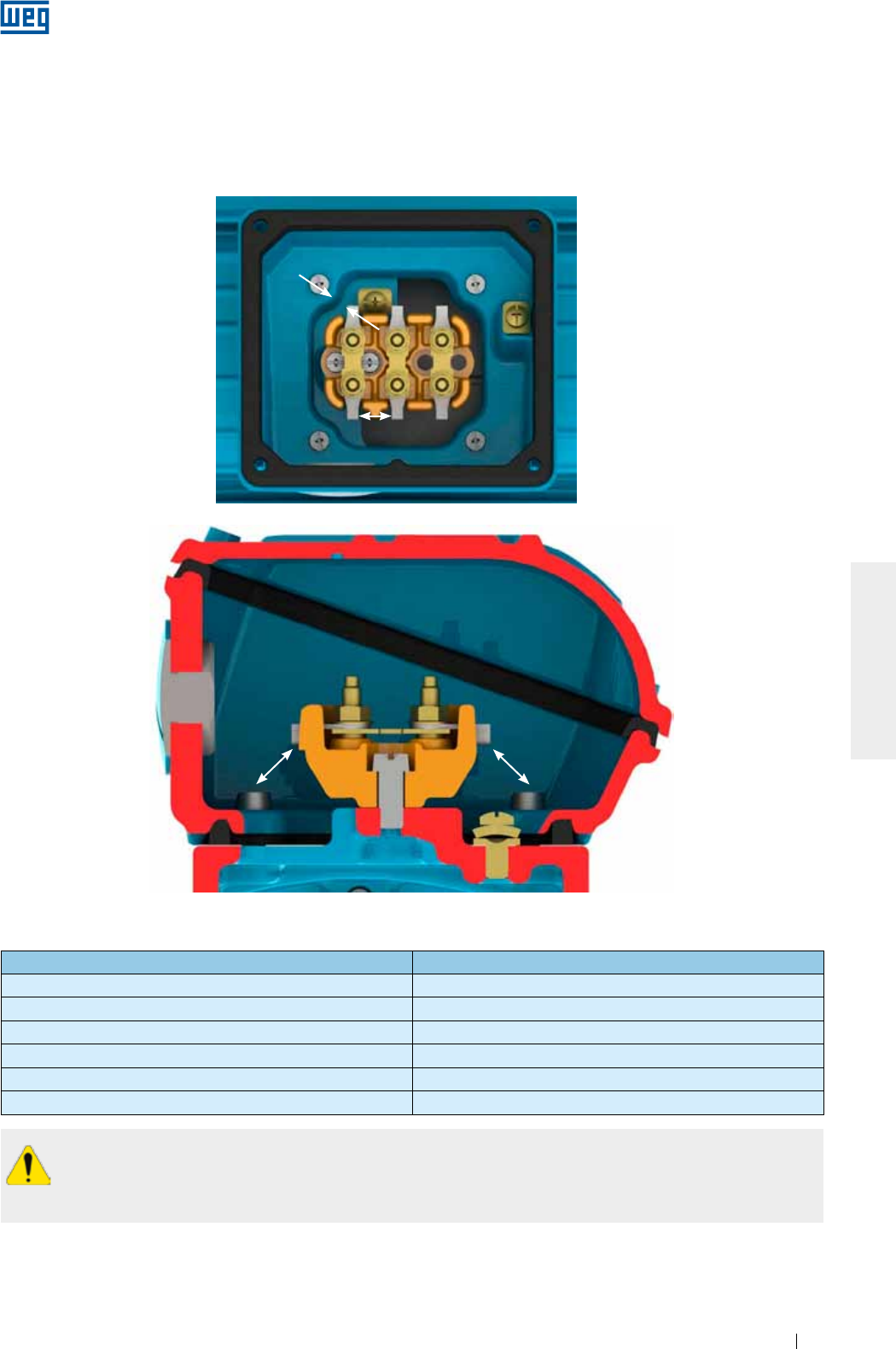
www.weg.net
Manual of Electric Motors 87
ENGLISH
Even when the motor is off, dangerous voltages may be present inside the terminal box used for the
space heater supply or winding energization when the winding is used as heating element.
Motor capacitors will hold a charge even after the power has been cut off. Do not touch the capacitors
and/or motor terminals, before discharging the capacitors completely.
Table 6.3 - Minimum clearance distance (mm) x supply voltage
Voltage Minimum clearance distance (mm)
U ≤ 440 V 4
440 < U ≤ 690 V 5.5
690 < U ≤ 1000 V 8
1000 < U ≤ 6900 V 45
6900 < U ≤ 11000 V 70
11000 < U ≤ 16500 V 105
If motors are supplied without terminal blocks, insulate the cable terminals with suitable insulation material that
meets the power supply voltage and the insulation class indicated on the motor nameplate.
Ensure correct tightening torque for the power cable and grounding connections as specified in Table 8.7
The clearance distance (see Figure 6.13) between non-insulated live parts with each other and between
grounded parts must be as indicated in Table 6.3.
Clearance distance
Clearance distance
Clearance distance Clearance distance
Figure 6.13 - Clearance distance representation
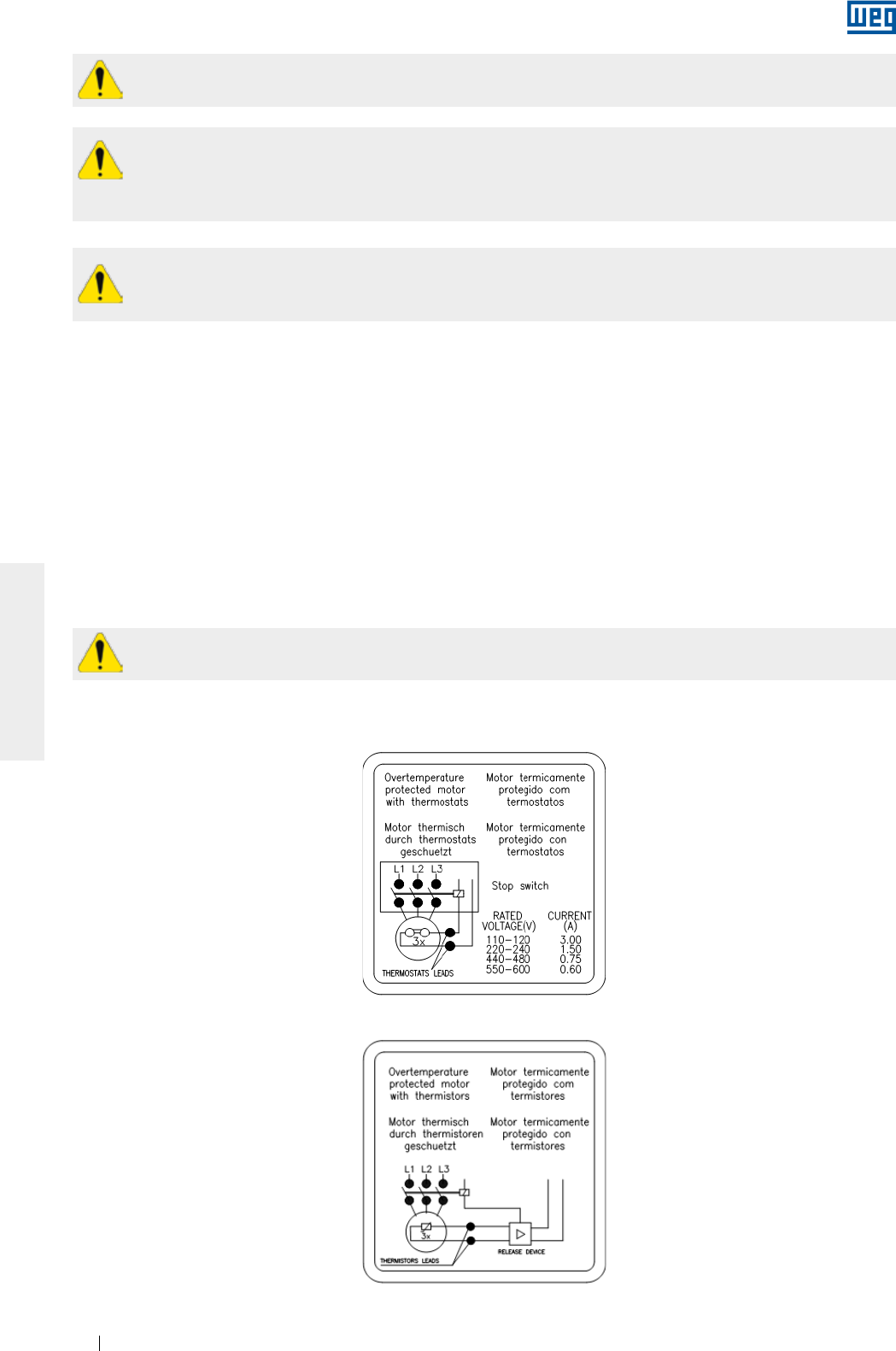
www.weg.net
Manual of Electric Motors88
ENGLISH
Unused cable inlet holes in the terminal box must be properly closed to ensure the degree of protection
indicated on the motor nameplate.
The cable inlets used for power supply and control must be fitted with components (for example, cable-
glands and conduits) that meet the applicable standards and regulations in each country.
If the motor is fitted with accessories, such as brakes and forced cooling systems, these devices must
be connected to the power supply according to the information provided on their nameplates and with
special care as indicated above.
Do not apply test voltage above 2.5 V on thermistors and current above 1 mA on RTDs (Pt-100)
according to IEC 60751 standard.
After the motor connection has been completed, ensure that no tool or foreign body has been left inside
the terminal box.
All protection devices, including overcurrent protection, must be set according to the rated machine conditions.
These protection devices must protect the machine against short circuit, phase fault or locked rotor condition.
The motor protection devices must be set according to the applicable standards.
Check the direction of rotation of the motor shaft. If there is no limitation for the use of unidirectional fans, the
shaft rotation direction can be changed by reversing any two of the phase connections. For single-phase motor,
check the connection diagram indicated on the motor nameplate.
Figure 6.14 and Figure 6.15 show the connection diagram of the bimetal thermal protector (thermostats) and
thermistors, respectively.
6.10. CONNECTION OF THE THERMAL PROTECTION DEVICES
If the motor is supplied with temperature monitoring devices, such as, thermostat, thermistors, automatic
thermal protectors, Pt-100 (RTD), etc., they must be connected to the corresponding control devices as
specified on the accessory nameplates. The non-compliance with this procedure may void the product
warranty and cause serious material damages.
Figure 6.14 - Connection of the bimetal thermal protectors (thermostats)
Figure 6.15 - Thermistor connection
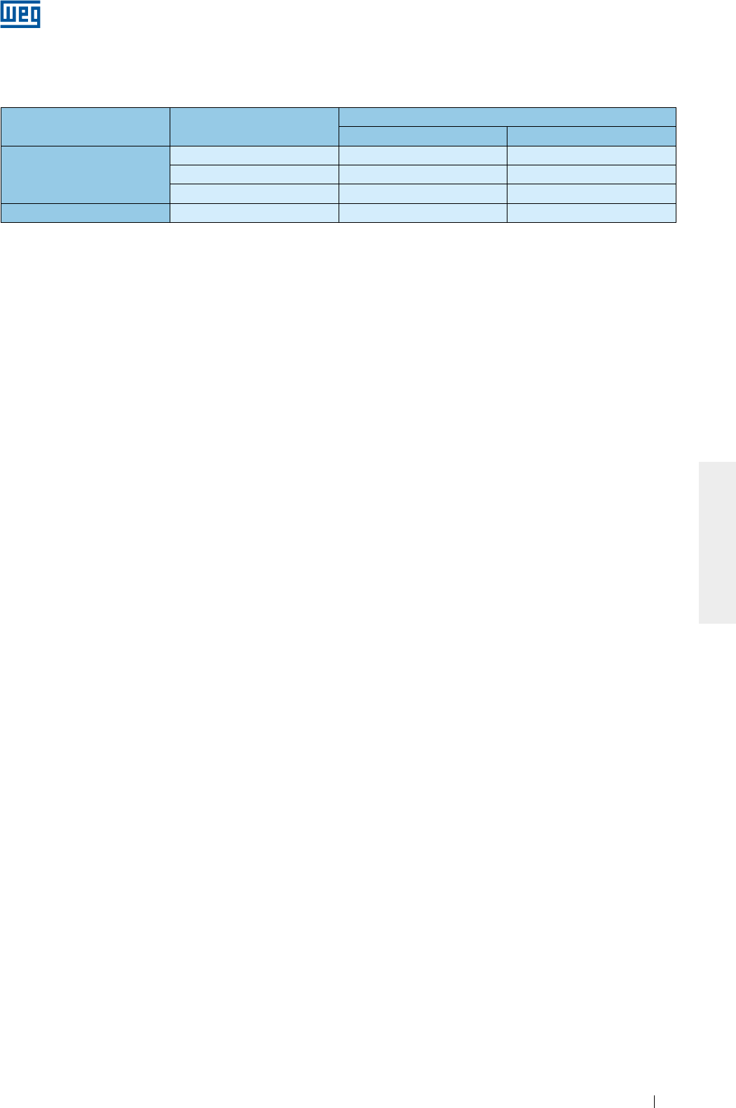
www.weg.net
Manual of Electric Motors 89
ENGLISH
The alarm temperature limits and thermal protection shutdowns can be defined according to the application;
however these temperature limits can not exceed the values in Table 6.4.
Table 6.4 - Maximum activation temperature of the thermal protections
Component Insulation class Maximum temperature of the protection setting (°C)
Alarm Tripping
Winding
B - 130
F 130 155
H 155 180
Bearing All 110 120
Notes:
1) The number and type of the installed protection devices are stated on the accessory nameplate of the motor.
2) If the motor is supplied with calibrated resistance, (for example, Pt-100), the motor protection system must be set according to the
operating temperatures indicated in Table 6.4.
6.11. RESISTANCE TEMPERATURE DETECTORS (PT-100)
The thermocouples Pt-100 are made of materials, whose resistance depends on the temperature variation,
intrinsic property of some materials (usually platinum, nickel or copper), calibrated resistance. Its operation is
based on the principle that the electric resistance of a metallic conductor varies linearly with the temperature,
thus allowing a continuous monitoring of the motor warm-up through the controller display ensuring a high level
of precision and answer stability. These devices are widely used for measuring temperatures in various industry
sectors.
In general these devices are used in installations where precise temperature control is required, for example, in
installation for irregular or intermittent duty.
The same detector may be used for alarm and tripping purposes.
Table 6.5 and Figure 6.16 show the equivalence between the Pt-100 resistance and the temperature.
www.weg.net
Manual of Electric Motors90
ENGLISH
Table 6.5 - Equivalence between the Pt-100 resistance and the temperature
ºC ºC ºC ºC ºC
-29 88.617 17 106.627 63 124.390 109 141.908 155 159.180
-28 89.011 18 107.016 64 124.774 110 142.286 156 159.553
-27 89.405 19 107.404 65 125.157 111 142.664 157 159.926
-26 89.799 20 107.793 66 125.540 112 143.042 158 160.298
-25 90.193 21 108.181 67 125.923 113 143.420 159 160.671
-24 90.587 22 108.570 68 126.306 114 143.797 160 161.043
-23 90.980 23 108.958 69 126.689 115 144.175 161 161.415
-22 91.374 24 109.346 70 127.072 116 144.552 162 161.787
-21 91.767 25 109.734 71 127.454 117 144.930 163 162.159
-20 92.160 26 110.122 72 127.837 118 145.307 164 162.531
-19 92.553 27 110.509 73 128.219 119 145.684 165 162.903
-18 92.946 28 110.897 74 128.602 120 146.061 166 163.274
-17 93.339 29 111.284 75 128.984 121 146.438 167 163.646
-16 93.732 30 111.672 76 129.366 122 146.814 168 164.017
-15 94.125 31 112.059 77 129.748 123 147.191 169 164.388
-14 94.517 32 112.446 78 130.130 124 147.567 170 164.760
-13 94.910 33 112.833 79 130.511 125 147.944 171 165.131
-12 95.302 34 113.220 80 130.893 126 148.320 172 165.501
-11 95.694 35 113.607 81 131.274 127 148.696 173 165.872
-10 96.086 36 113.994 82 131.656 128 149.072 174 166.243
-9 96.478 37 114.380 83 132.037 129 149.448 175 166.613
-8 96.870 38 114.767 84 132.418 130 149.824 176 166.984
-7 97.262 39 115.153 85 132.799 131 150.199 177 167.354
-6 97.653 40 115.539 86 133.180 132 150.575 178 167.724
-5 98.045 41 115.925 87 133.561 133 150.950 179 168.095
-4 98.436 42 116.311 88 133.941 134 151.326 180 168.465
-3 98.827 43 116.697 89 134.322 135 151.701 181 168.834
-2 99.218 44 117.083 90 134.702 136 152.076 182 169.204
-1 99.609 45 117.469 91 135.083 137 152.451 183 169.574
0 100.000 46 117.854 92 135.463 138 152.826 184 169.943
1 100.391 47 118.240 93 135.843 139 153.200 185 170.313
2 100.781 48 118.625 94 136.223 140 153.575 186 170.682
3 101.172 49 119.010 95 136.603 141 153.950 187 171.051
4 101.562 50 119.395 96 136.982 142 154.324 188 171.420
5 101.953 51 119.780 97 137.362 143 154.698 189 171.789
6 102.343 52 120.165 98 137.741 144 155.072 190 172.158
7 102.733 53 120.550 99 138.121 145 155.446 191 172.527
8 103.123 54 120.934 100 138.500 146 155.820 192 172.895
9 103.513 55 121.319 101 138.879 147 156.194 193 173.264
10 103.902 56 121.703 102 139.258 148 156.568 194 173.632
11 104.292 57 122.087 103 139.637 149 156.941 195 174.000
12 104.681 58 122.471 104 140.016 150 157.315 196 174.368
13 105.071 59 122.855 105 140.395 151 157.688 197 174.736
14 105.460 60 123.239 106 140.773 152 158.061 198 175.104
15 105.849 61 123.623 107 141.152 153 158.435 199 175.472
16 106.238 62 124.007 108 141.530 154 158.808 200 175.840
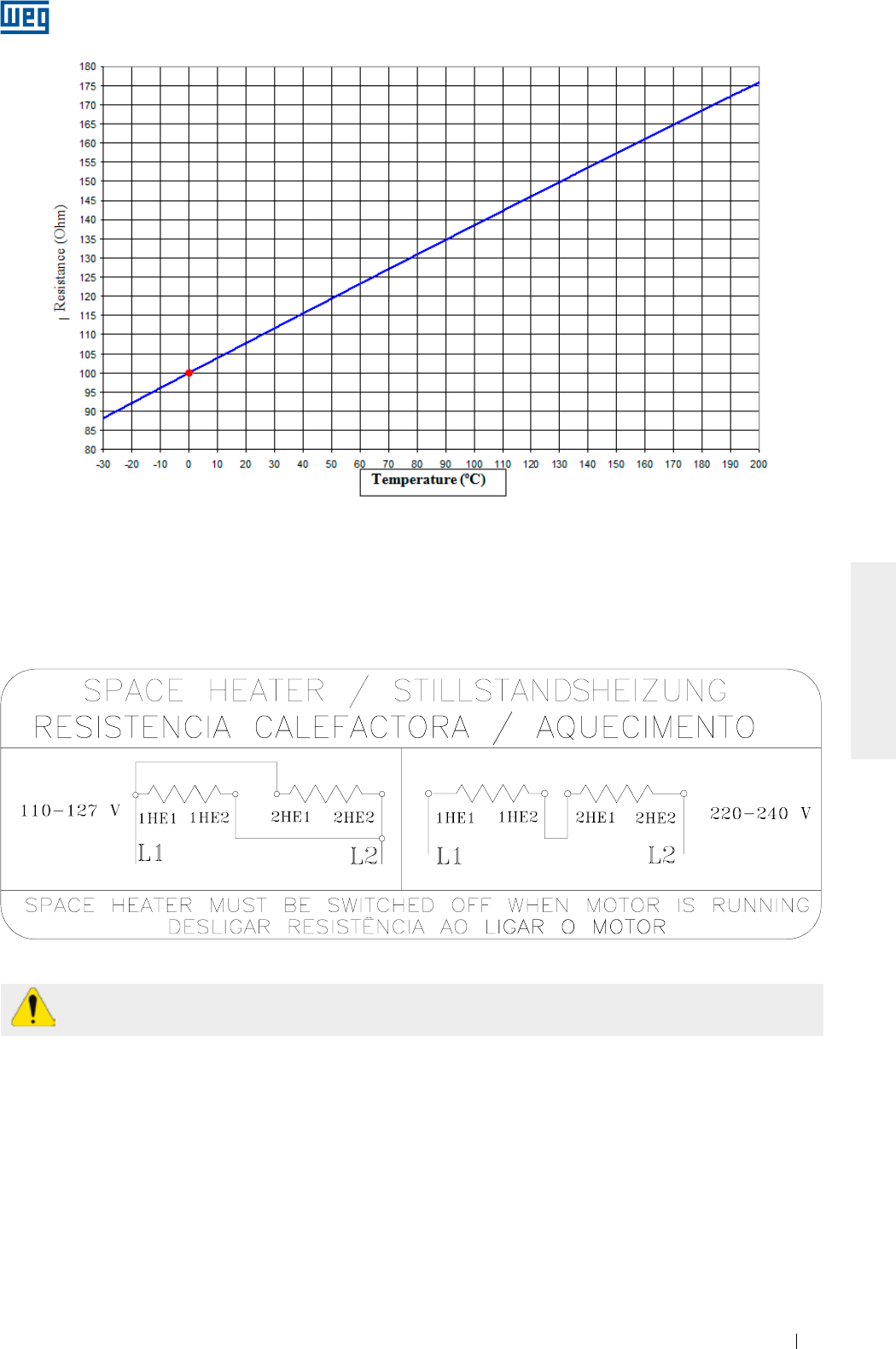
www.weg.net
Manual of Electric Motors 91
ENGLISH
Figure 6.16 - Ohmic resistance of the Pt-100 x temperature
6.12. CONNECTION OF THE SPACE HEATERS
Before switching ON the space heaters, check if the space heaters connection have been made according to
the connection diagram shown on the space heater nameplate. For motors supplied with dual voltage space
heaters (110-127/220-240 V), see Figure 6.17.
Figure 6.17 - Dual voltage space heater connection
The space heaters should never be energized when the motor is in operation.
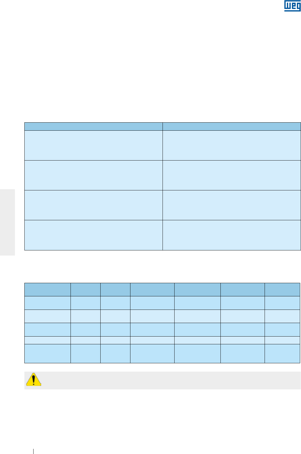
www.weg.net
Manual of Electric Motors92
ENGLISH
6.13. STARTING METHODS
Whenever possible, the motor starting must be Direct On Line (DOL) at rated voltage. This is the most simple
and feasible starting method. However, it must only be applied when the starting current does not affect the
power supply. Please consider the local electric utility regulations when installing a motor.
High inrush current may result in:
a) high voltage drop in the power supply line creating unacceptable line disturbance on the distribution system;
b) requiring oversized protection system (cables and contactor) increasing the installation costs.
If DOL starting is not allowed due to the reasons mentioned above, an indirect starting method compatible with
the load and motor voltage to reduce the starting current may be used.
If reduced voltage starters are used for starting, the motor starting torque will also be reduced.
Table 6.6 shows the possible indirect starting methods that can be used depending on the number of the
motor leads.
Table 6.6 - Starting method x number of motor leads
Number of leads Possible starting methods
3 leads Autotransformer
Soft-starter
6 leads
Star-Delta
Autotransformer
Soft-starter
9 leads
Series/Parallel
Part winding
Autotransformer
Soft-starter
12 leads
Star-Delta
Series/Parallel
Part winding
Autotransformer
Soft-starter
Table 6.7 - Starting methods x voltage
Table 6.7 shows examples of possible indirect starting methods to be used according to the voltage indicated
on the motor nameplate and the power supply voltage.
Nameplate
voltage
Operating
voltage Star-delta Autotransformer
starting
Starting by series/
parallel switch
Part-winding
starting
Starting by
Soft-starter
220/380 V 220 V
380 V
YES
NO
YES
YES
NO
NO
NO
NO
YES
YES
220/440 V 220 V
440 V
NO
NO
YES
YES
YES
NO
YES
NO
YES
YES
230/460 V 230 V
460 V
NO
NO
YES
YES
YES
NO
YES
NO
YES
YES
380/660 V 380 V YES YES NO NO YES
220/380/440 V
220 V
380 V
440 V
YES
NO
YES
YES
YES
YES
YES
YES
NO
YES
YES
NO
YES
YES
YES
The WQuattro line motors must be started direct on-line (DOL) or driven by a frequency inverter in scalar
mode.
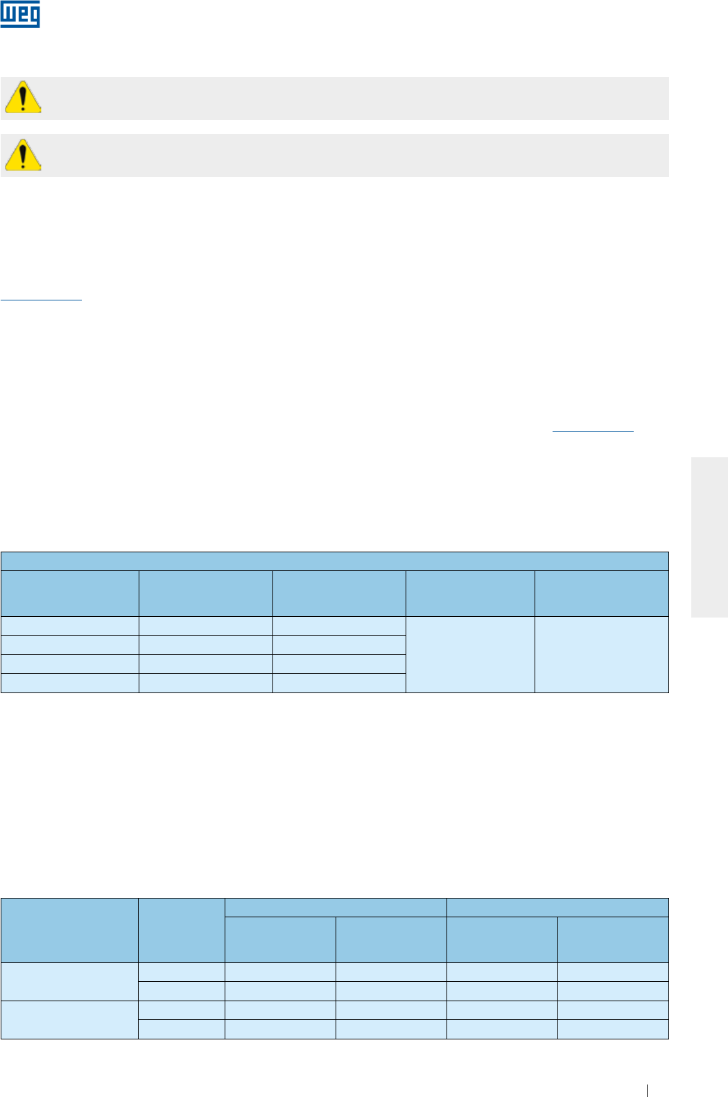
www.weg.net
Manual of Electric Motors 93
ENGLISH
The operation with frequency inverter must be stated in the Purchase Order since this drive type may
require some changes of the motor design.
Wmagnet Motors must only be driven by WEG frequency inverter.
6.14. MOTORS DRIVEN BY FREQUENCY INVERTER
6.14.1. Use of dV/dt filter
6.14.1.1. Motor with enameled round wire
Motors designed for rated voltages up to 690 V, when driven by frequency inverter, do not require the use of
dV/dT filters, provided that following criteria are considered.
The frequency inverter used to drive motors up to 690 V must be fitted with Pulse With Modulation (PWM) with
vector control.
When a motor is driven by a frequency inverter at lower frequencies than the rated frequency, you must reduce
the motor torque to prevent motor overheating. The torque reduction (derating torque) can be found in the item
6.4 of the “Technical Guidelines for Induction Motors driven by PWM Frequency inverters” available on the site
www.weg.net.
If the motor is operated above the rated frequency, please note:
g That the motor must be operated at constant output;
g That the motor can supply max. 95% of its rated output;
g Do not exceed the maximum speed and please consider:
g max. operating frequency stated on the additional nameplate;
g mechanical speed limitation of the motor.
Information on the selection of the power cables between the frequency inverter and the motor can be found in the item
6.4 of the “Technical Guidelines for Induction Motors driven by PWM Frequency inverters” available at www.weg.net.
Criteria for the selection of motors with round enameled wire when driven by frequency inverter 1
Motor rated votage 2Peak voltage at the
motor terminals (max)
dV/dt
inverter output (max)
Inverter
Rise Time 3
(min.)
MTBP 3
Time between pulses
(min)
Vnom ≤ 460 V ≤ 1600 V ≤ 5200 V/µs
≥ 0,1 µs ≥ 6 µs
460 < Vnom ≤ 575 V ≤ 1800 V ≤ 6500 V/µs
575 < Vnom ≤ 690 V 4≤ 1600 V ≤ 5200 V/µs
575 < Vnom ≤ 690 V 5≤ 2200 V ≤ 7800 V/µs
Notes:
1. For the application of motors with round enameled wires designed for 690 < Vnom ≤ 1100 V, please contact WEG.
2. For the application of dual voltage motors, example 380/660 V, consider the lower voltage (380 V).
3. Information supplied by the inverter manufacturer.
4. When not stated in the Purchase Order that the motor will be driven by frequency inverter.
5. When stated in the Purchase Order that the motor will be driven by frequency inverter.
6.14.1.2. Motor with prewound coils
Motors with prewound coils (medium and high voltage motors regardless of frame sizes, and low voltage
motors from IEC 500 / NEMA 800 frame on), designed for the use with frequency inverters, do not require the
use of filters, provided they comply with the criteria in Table 6.8.
Table 6.8 - Criteria to be considered when using motor with prewound coils to be drive by frequency inverters
Motor rated voltage Type of
modulation
Turn to turn insulation (phase-phase) Phase-ground insulation
Peak voltage at
the motor
terminals
dV/dt at the motor
terminals
Peak voltage at
the motor
terminals
dV/dt at the motor
terminals
690 < Vnom ≤ 4160 V Sinusoidal ≤ 5900 V ≤ 500 V/µs ≤ 3400 V ≤ 500 V/µs
PWM ≤ 9300 V ≤ 2700 V/µs ≤ 5400 V ≤ 2700 V/µs
4160 < Vnom ≤ 6600 V Sinusoidal ≤ 9300 V ≤ 500 V/µs ≤ 5400 V ≤ 500 V/µs
PWM ≤ 14000 V ≤ 1500 V/µs ≤ 8000 V ≤ 1500 V/µs
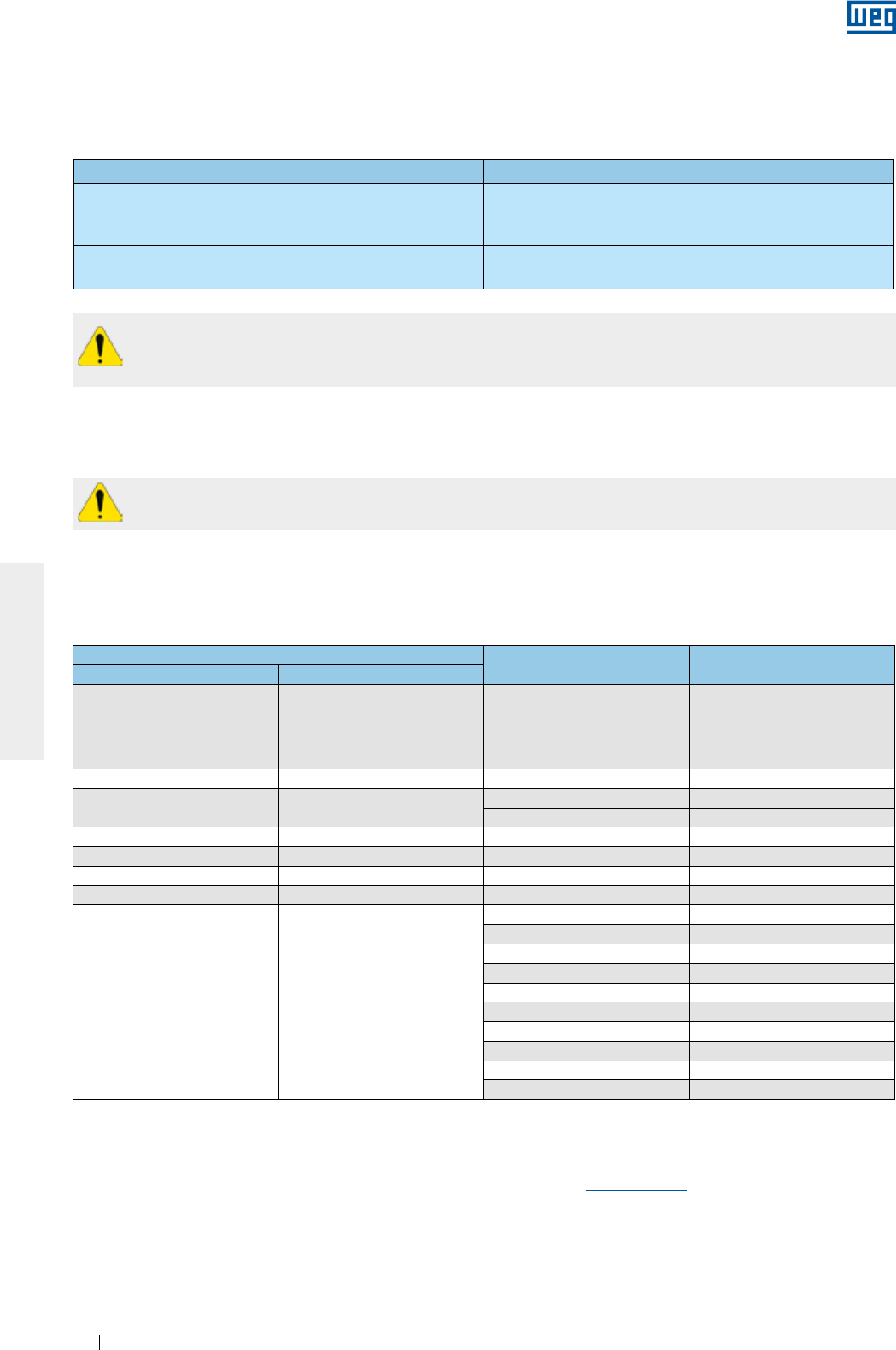
www.weg.net
Manual of Electric Motors94
ENGLISH
When motors are supplied with shaft grounding system, monitor the grounding brush constantly during
its operation and, when it reaches the end of its useful life, it must be replaced by another brush with the
same specification.
The non-compliance with the criteria and recommendations indicated in this manual may void the
product warranty.
6.14.2. Bearing insulation
Only the motors in IEC frame size 400 (NEMA 680) and larger are supplied, as standard, with insulated bearing.
If motor must be driven by frequency inverter, insulate the bearing according to Table 6.9.
6.14.3. Switching frequency
The minimum inverter switching frequency must not be lower than 2.5 kHz and should not exceed 5 kHz.
Table 6.9 - Recommendation on the bearing insulation for inverter driven motors
Frame size Recommendation
IEC 315 and 355
NEMA 445/7, 447/9, L447/9, 504/5, 5006/7/8, 5009/10/11, 586/7,
5807/8/9, 5810/11/12 and 588/9
g Insulated bearing/end shield
g Grounding between shaft and frame by grounding brush
IEC 400 and larger
NEMA 680 and larger
g Insulated NDE bearing
g Grounding between shaft and frame by grounding brush
Note:
To select the maximum allowed motor speed, consider the motor torque derating curve.
For more information on the application of frequency inverters, contact WEG or check the “Technical Guidelines
for Induction Motors driven by PWM Frequency inverters” available at www.weg.net.
6.14.4. Mechanical speed limitation
Table 6.10 shows the maximum speeds allowed for motors driven by frequency inverter.
Table 6.10 - Maximum motor speed (in rpm)
Frame size DE-bearing Maximum speed for
standard motors
IEC NEMA
63-90 143/5
6201
6202
6203
6204
6205
10400
100 - 6206 8800
112 182/4 6207 7600
6307 6800
132 213/5 6308 6000
160 254/6 6309 5300
180 284/6 6311 4400
200 324/6 6312 4200
225-630 364/5-9610
6314 3600
6315 3600
6316 3200
6319 3000
6220 3600
6320 2200
6322 1900
6324 1800
6328 1800
6330 1800
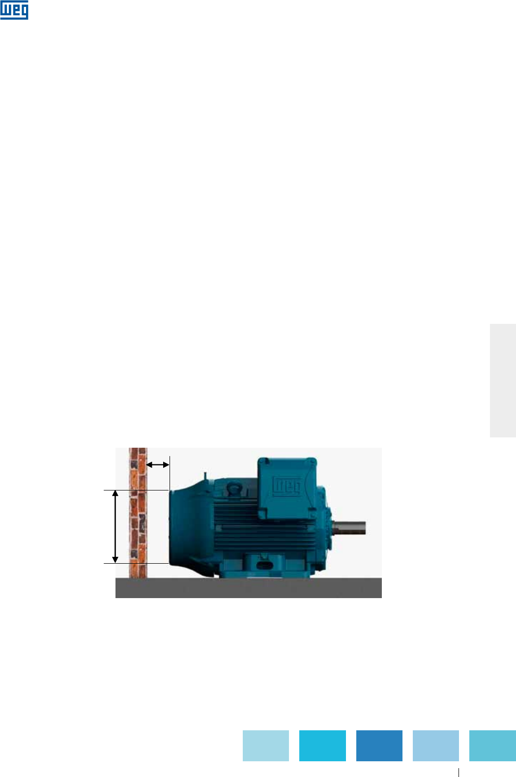
www.weg.net
Manual of Electric Motors 95
ENGLISH
L
D
Figure 7.1- Minimum clearance to the wall
7. COMMISSIONING
7.1. INITIAL START-UP
After finishing the installation procedures and before starting the motor for the first time or after a long period
without operation, the following items must be checked:
g If the nameplate data (voltage, current, connection diagram, degree of protection, cooling system, service
factor, etc.) meet the application requirements;
g If the machine set (motor + driven machine) has been mounted and aligned correctly;
g If the motor driving system ensures that the motor speed does not exceed the max. allowed speed indicated
in Table 6.10;
g Measure the winding insulation resistance, making sure it complies with the specified values in item 5.4;
g Check the motor rotation direction;
g Inspect the motor terminal box for damage and ensure that it is clean and dry and all contacts are rust-free,
the seals are in perfect operating conditions and all unused threaded holes are properly closed thus ensuring
the degree of protection indicated on the motor nameplate;
g Check if the motor wiring connections, including grounding and auxiliary equipment connection, have been
carried out properly and are in accordance with the recommendations in item 6.9;
g Check the operating conditions of the installed auxiliary devices (brake, encoder, thermal protection device,
forced cooling system, etc.);
g Check bearing operating conditions. If signs of oxidation are detected, replace the bearings. If no sign of
oxidation is detected, relubricate the bearings as described in item 8.2. If the motors are stored for more than
two years, the bearings must be replaced before starting the motor;
g When motors are fitted with sleeve bearings, ensure:
g Correct oil level for the sleeve bearing. The oil level should be in the center of the sight glass (see Figure 6.8);
g That the motor is not started or operated with axial or radial loads;
g That if the motor is stored for a period equal or longer than the oil change interval, the oil must be changed
before starting the motor.
g Inspect the capacitor operating condition, if any. If motors are installed for more than two years, but were
never commissioned, it is recommended to change the start capacitors since they lose their operating
characteristics;
g Ensure that the air inlet and outlet opening are not blocked. The minimum clearance to the nearest wall (L)
should be at least ¼ of the fan cover diameter (D), see Figure 7.1. The intake air temperature must be at
ambient temperature.
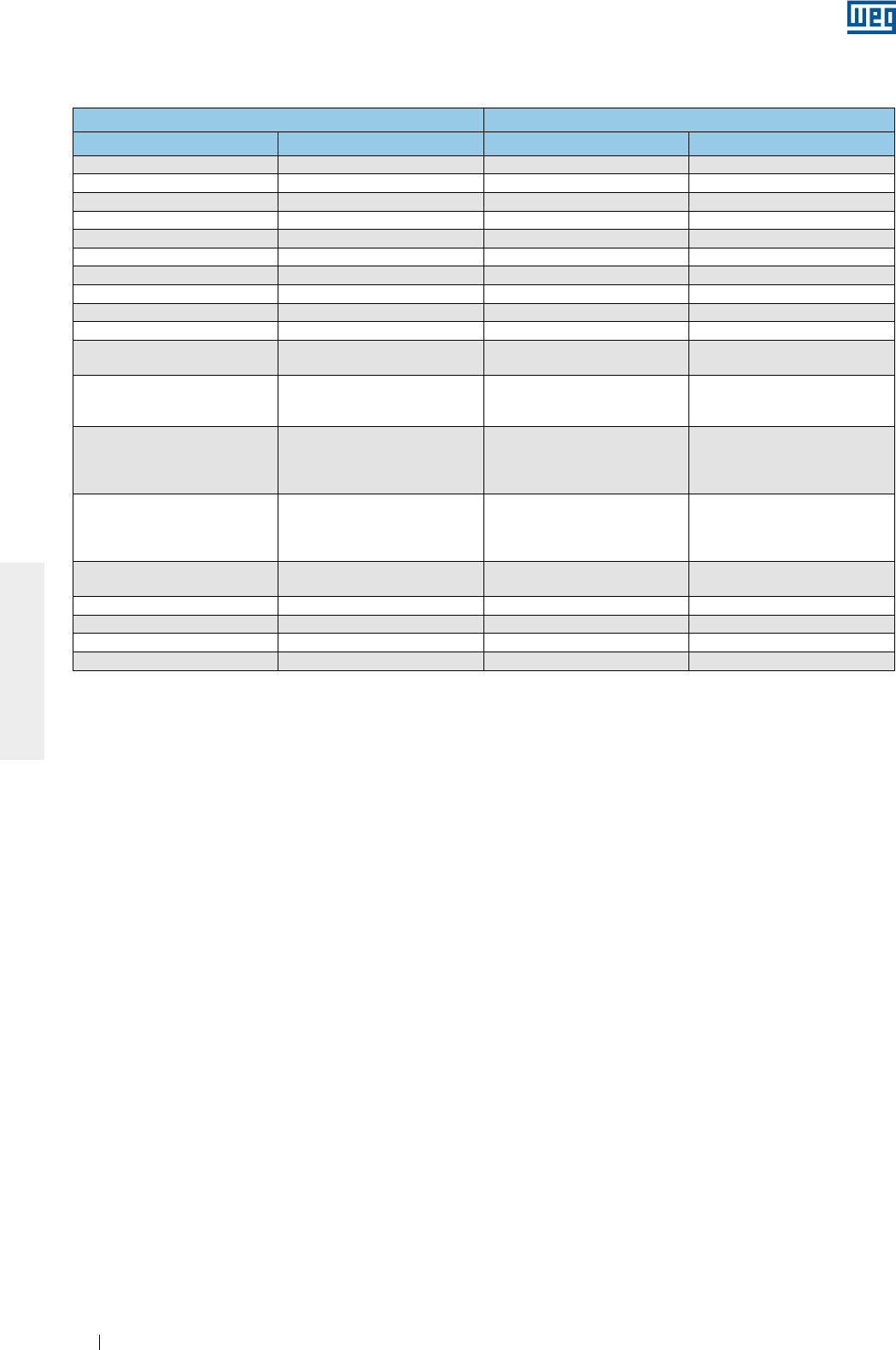
www.weg.net
Manual of Electric Motors96
ENGLISH
Please consider the minimum distances shown in the Table 7.1 as reference value;
g Ensure correct water flow rate and water temperature when water cooled motors are used. See item 7.2;
g Ensure that all rotating parts, such as pulleys, couplings, external fans, shaft, etc. are protected against
accidental contact.
Other tests and inspections not included in the manual may be required, depending on the specific installation,
application and/or motor characteristics.
After all previous inspections have been carried out, proceed as follows to start the motor:
g Start the motor on no-load (if possible) and check the motor direction of rotation. Check for the presence of
any abnormal noise, vibration or other abnormal operating conditions;
g Ensure the motor starts smoothly. If any abnormal operating condition is noticed, switch off the motor, check
the assembly system and connections before the motor is started again;
g If excessive vibrations are noticed, check if the motor mounting bolts are well tightened or if the vibrations are
not generated and transmitted from adjacent installed equipment. Check the motor vibration periodically and
ensure that the vibration limits are as specified in item 7.2.1;
g Start the motor at rated load during a short time and compare the operating current with the rated current
indicated on the nameplate;
g Continue to measure the following motor variables until thermal equilibrium is reached: current, voltage,
bearing and motor frame temperature, vibration and noise levels;
g Record the measured current and voltage values on the Installation Report for future comparisons.
As induction motors have high inrush currents during start-up, the acceleration of high inertia load requires an
extended starting time to reach full speed resulting in fast motor temperature rise. Successive starts within
short intervals will result in winding temperature increases and can lead to physical insulation damage reducing
the useful life of the insulation system. If the duty cycle S1 / CONT. is specified on the motor nameplate, this
means that the motor has been designed for:
g Two successive starts: first start from cold condition, i. e., the motor windings are at room temperature and
the second start immediately after the motor stops;
g One start from hot condition, i. e., the motor windings are at rated temperature.
The Troubleshooting Chart in section 10 provides a basic list of unusual cases that may occur during motor
operation with the respective corrective actions.
Table 7.1 - Minimum distance between the fan cover and wall
Frame size Distance between the fan cover and the wall (L)
IEC NEMA mm inches
63 - 25 0.96
71 - 26 1.02
80 - 30 1.18
90 143/5 33 1.30
100 - 36 1.43
112 182/4 41 1.61
132 213/5 50 1.98
160 254/6 65 2.56
180 284/6 68 2.66
200 324/6 78 3.08
225
250
364/5
404/5 85 3.35
280
444/5
445/7
447/9
108 4.23
315
L447/9
504/5
5006/7/8
5009/10/11
122 4.80
355
586/7
588/9
5807/8/9
5810/11/12
136 5.35
400 6806/7/8
6809/10/11 147 5.79
450 7006/10 159 6.26
500 8006/10 171 6.73
560 8806/10 185 7.28
630 9606/10 200 7.87

www.weg.net
Manual of Electric Motors 97
ENGLISH
Table 7.3 - Minimum required air speed between motor fins (metres/second)
7.2. OPERATING CONDITIONS
Unless otherwise stated in the Purchase Order, electric motors are designed and built to be operated at
altitudes up to 1000 meters above sea level and in a temperature range from -20 °C to +40 °C. Any deviation
from the normal condition of motor operation must be stated on the motor nameplate. Some components must
be changed if the ambient temperature is different from the specified one. Please contact WEG to check the
required special features.
For operating temperatures and altitudes differing from those above, the factors indicated in Table 7.2 must be
applied to the nominal motor power rating in order to determine the derated available output (Pmax = Pnom x
correction factor).
Motors installed inside enclosures (cubicles) must be ensured an air renewal rate in the order of one cubic
meter per second for each 100 kW installed power or fraction of installed power. Totally Enclosed Air Over
motors - TEAO (fan and exhaust / smoke extraction) are supplied without cooling fan and the manufacturer of
the driven machine is responsible for sufficient motor cooling. If no minimum required air speed between motor
fins is indicated on the motor nameplate, ensure the air speed indicated in the table 7.3 is provided. The values
shown in Table 7.3 are valid for 60 Hz motors. To obtain the minimum air speed for 50 Hz motors, multiply the
values in the table by 0.83.
Frame Poles
IEC NEMA 2 4 6 8
63 to 90 143/5 14 7 5 4
100 to 132 182/4 to 213/5 18 10 8 6
160 to 200 254/6 to 324/6 20 20 12 7
225 to 280 364/5 to 444/5 22 22 18 12
315 to 355 445/7 to 588/9 25 25 20 15
The voltage and frequency variations may affect the performance characteristics and the electromagnetic
compatibility of the motor. The power supply variations should not exceed the values specified in the applicable
standards. Examples:
g ABNT NBR 17094 - Parts 1 and 2. The motor has been designed to supply the rated torque for a combined
variation in voltage and frequency:
g Zone A: ±5% of the rated voltage and ±2% of the rated frequency;
g Zone B: ±10% of the rated voltage and +3% -5% of the rated frequency.
When operated continuously in Zone A or B, the motor may show performance variations and the operating
temperature may increase considerably. These performance variations will be higher in Zone B. Thus it is not
recommended to operate the motor in Zone B during extended periods.
g IEC 60034-1. The motor has been designed to supply the rated torque for combined variation in voltage and
frequency:
g Zone A: ±5% of the rated voltage and ±2% of the rated frequency;
g Zone B: ±10% of the rated voltage and +3% -5% of the rated frequency.
When operated continuously in Zone A or B, the motor may show performance variations and the operating
temperature may increase considerably. These performance variations will be higher in Zone B. Thus it is not
recommended to operate the motor in Zone B during extended periods. For multivoltage motors (example 380-
415/660 V), a ±5% voltage variation from the rated voltage is allowed.
Table 7.2 - Correction factors for altitude and ambient temperature
T (°C) Altitude (m)
1000 1500 2000 2500 3000 3500 4000 4500 5000
10 0.97 0.92 0.88
15 0.98 0.94 0.90 0.86
20 1.00 0.95 0.91 0.87 0.83
25 1.00 0.95 0.93 0.89 0.85 0.81
30 1.00 0.96 0.92 0.90 0.86 0.82 0.78
35 1.00 0.95 0.93 0.90 0.88 0.84 0.80 0.75
40 1.00 0.97 0.94 0.90 0.86 0.82 0.80 0.76 0.71
45 0.95 0.92 0.90 0.88 0.85 0.81 0.78 0.74 0.69
50 0.92 0.90 0.87 0.85 0.82 0.80 0.77 0.72 0.67
55 0.88 0.85 0.83 0.81 0.78 0.76 0.73 0.70 0.65
60 0.83 0.82 0.80 0.77 0.75 0.73 0.70 0.67 0.62
65 0.79 0.76 0.74 0.72 0.70 0.68 0.66 0.62 0.58
70 0.74 0.71 0.69 0.67 0.66 0.64 0.62 0.58 0.53
75 0.70 0.68 0.66 0.64 0.62 0.60 0.58 0.53 0.49
80 0.65 0.64 0.62 0.60 0.58 0.56 0.55 0.48 0.44
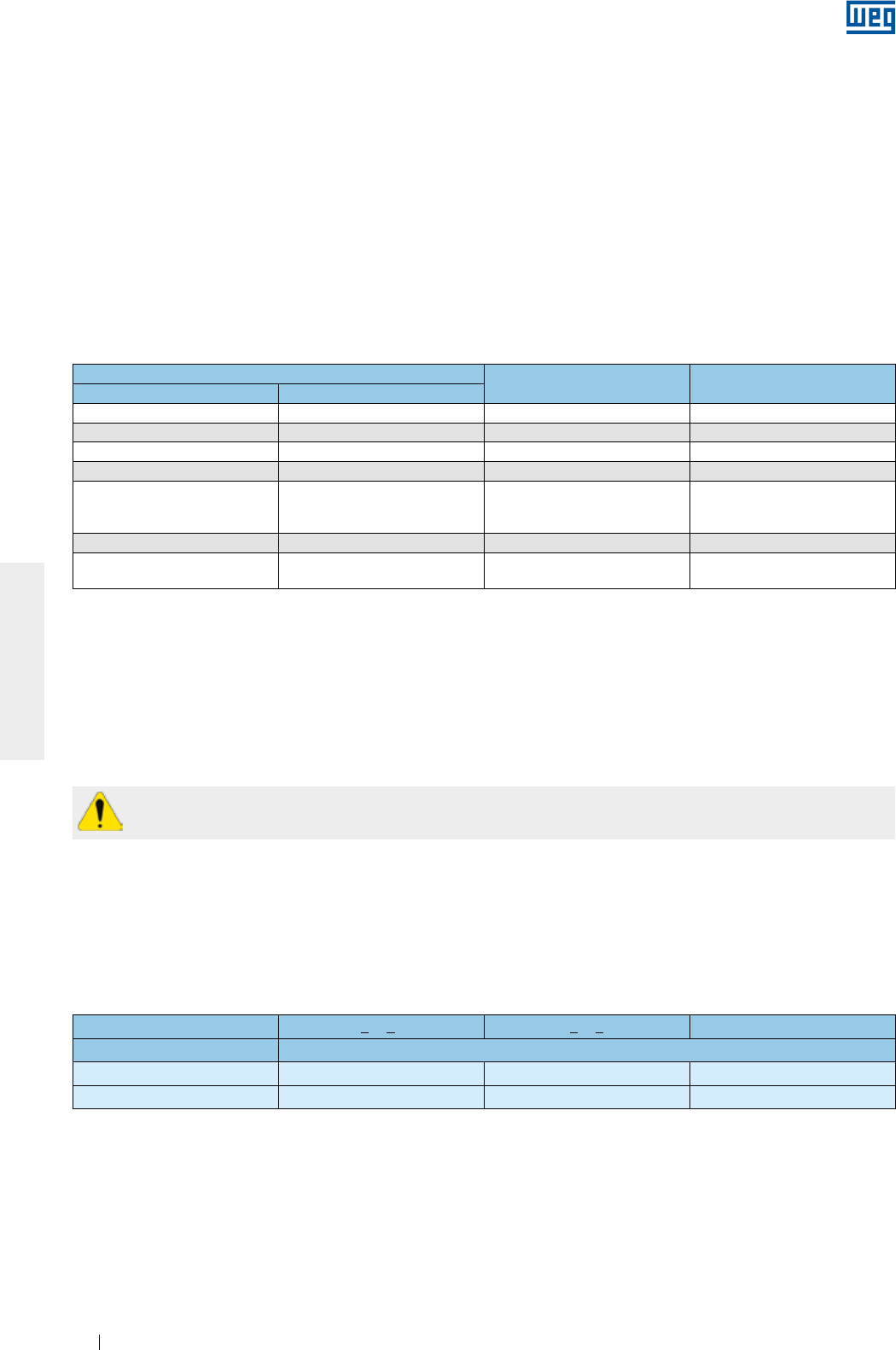
www.weg.net
Manual of Electric Motors98
ENGLISH
Motors fitted with cylindrical roller bearings require a minimum radial load to ensure a normal operation.
For information regarding the radial preload, please contact WEG.
7.2.1.Limits of vibration
The vibration severity is the maximum vibration value measured at all positions and in all directions as
recommended in the standard IEC 60034-14. Table 7.5 specifies the limits of the maximum vibrations
magnitudes according to standard IEC 60034-14 for shaft heights IEC 56 to 400, for vibrations grades A and B.
The vibration severity limits in Table 7.5 are given as RMS values (Root Mean Square values or effective values)
of the vibration speed in mm/s measured in free suspension condition.
Motors fitted with oil mist lubrication systems can be operated continuously for a maximum of one hour after
the failure of the oil pumping system.
Considering the sun’s heat increases the operating temperature, externally mounted motors should always be
protected from direct sunlight exposure.
Each and every deviation from the normal operating condition (tripping of the thermal protection, noise and
vibration level increase, temperature and current rise) should be investigated and corrected by WEG Authorized
Service Centers.
According to NEMA MG 1, the allowed vibration limit for standard motors is 0.15 in/s (peak vibration in in/s).
Table 7.4 - Minimum required water flow and the maximum allowed
temperature rise of the cooling water after circulating through the motor
Table 7.5 - Recommended limits for the vibration severity according to standard IEC 60034-14
Frame size Flow rate
(litres/minute)
Maximum allowed water
temperature rise (°C)
IEC NEMA
180 284/6 12 5
200 324/6 12 5
225 364/5 12 5
250 404/5 12 5
280
444/5
445/7
447/9
15 6
315 504/5 16 6
355 586/7
588/9 25 6
Shaft height [mm] 56 < H < 132 132 < H < 280 H > 280
Vibration grade Vibration severity on elastic base [mm/s RMS]
A 1.6 2.2 2.8
B 0.7 1.1 1.8
Notes:
1 - The values in Table 7.5 are valid for measurements carried out with decoupled machines (without load) operated at rated voltage and
frequency.
2 - The values in Table 7.5 are valid regardless of the direction of rotation of the machine.
3 - The values in Table 7.5 are not applicable to single-phase motors, three-phase motors powered by a single-phase system or to
machines mounted in situ or coupled with inertia flywheels or to loads.
Note:
For the load operation condition, the use of the standard ISO 10816-3 is recommended for evaluating the motor vibration limits. In the
load condition the motor vibration will be influenced by several factors, such as, type of the coupled load, condition of the motor fixation,
alignment condition under load, structure or base vibration due to other equipments, etc..
g NEMA MG 1 Part 12. The motor has been designed to be operated in one of the following variations:
g ±10% of the rated voltage, with rated frequency;
g ±5% of the rated frequency, with rated voltage;
g A combined variation in voltage and frequency of ±10%, provided the frequency variation does not exceed
±5%.
If the motor is cooled by ambient air, clean the air inlet and outlet openings and cooling fins at regular intervals
to ensure a free airflow over the frame surface. The hot air should never be returned to the motor. The cooling
air must be at room temperature limited to the temperature range indicated on the motor nameplate (if no room
temperature is specified, please consider a temperature range between -20 °C and +40 °C).
Table 7.4 shows the minimum required water flow for water cooled motors considering the different frame sizes
and the maximum allowed temperature rise of the cooling water after circulating through the motor. The inlet
water temperature should not exceed 40 °C.

www.weg.net
Manual of Electric Motors 99
ENGLISH
Do not reuse damaged or worn parts. Damaged or worn parts must be replaced by parts supplied by
the manufacturer and must be installed as if they were the original parts.
Please contact WEG when motors are to be installed in special environments or used for special
applications.
8.1. GENERAL INSPECTION
The inspection intervals depend on the motor type, application and installation conditions. Proceed as follows
during inspection:
g Visually inspect the motor and coupling. Check if abnormal noises, vibrations, excessive heating, wear signs,
misalignment or damaged parts are noticed. Replace the damaged parts as required;
g Measure the insulation resistance according to the item 5.4;
g Clean the motor enclosure. Remove oil spills and dust accumulation from the motor frame surface to ensure
a better heat transfer to the surrounding ambient;
g Check cooling fan condition and clean the air inlet & outlet openings to ensure a free air flow over the motor;
g Investigate the actual condition of the seals and replace them, if required;
g Drain the condensed water from inside the motor. After draining, reinstall the drain plugs to ensure the degree
of protection as indicated on the motor nameplate. The motor must always be positioned so the drain hole is
at the lowest position (see item 6);
g Check the connections of the power supply cables, ensuring the correct clearance distance between live and
grounded parts, as specified in Table 6.3;
g Check if the tightening torque of the bolted connections and mounting bolts meets the tightening torque
specified in Table 8.7;
g Check the status of the cable passages, the cable gland seals and the seals inside the terminal box and
replace them, if required;
g Check the bearing operating conditions. Check for the presence of any abnormal noise, vibration or other
abnormal operating conditions, like motor temperature rise. Check the oil level, the lube oil condition and
compare the workings hours with the informed life time;
g Record and file all changes performed on the motor.
8.2. LUBRICATION
Proper lubrication plays a vital role in the motor performance. Only use the grease or oil types, amounts and
lubrication intervals recommended for the bearings. This information is available on the motor nameplate and
the lubrication procedures must be carried out according to the type of lubricant (oil or grease).
When the motor is fitted with thermal protection devices for bearing temperature control, consider the operating
temperature limits shown in Table 6.4.
The maximum operating temperature of motors used in special applications may differ from those shown in
Table 6.4. The grease and oil disposal should be made in compliance with applicable laws in each country.
8. MAINTENANCE
The purpose of the maintenance is to extend the useful life of the equipment. The non-compliance with one of
these previous items can cause unexpected machine failures.
If motors with cylindrical roller or angular contact bearings are to be transported during the maintenance
procedures, the shaft locking device must always be fitted. All HGF motors, regardless of the bearing type,
must always be transported with the shaft locking device fitted.
All repairs, disassembly and assembly related services must be carried out only by qualified and well-trained
personnel by using proper tools and techniques. Make sure that the machine has stopped and it is
disconnected from the power supply, including the accessory devices (space heater, brake, etc.), before any
servicing is undertaken.
The company does not assume any responsibility or liability for repair services or maintenance operations
executed by non-authorized Service Centers or by non qualified service personnel. The company shall have no
obligation or liability whatsoever to the buyer for any indirect, special, consequential or incidental loss or
damage caused or arising from the company’s proven negligence
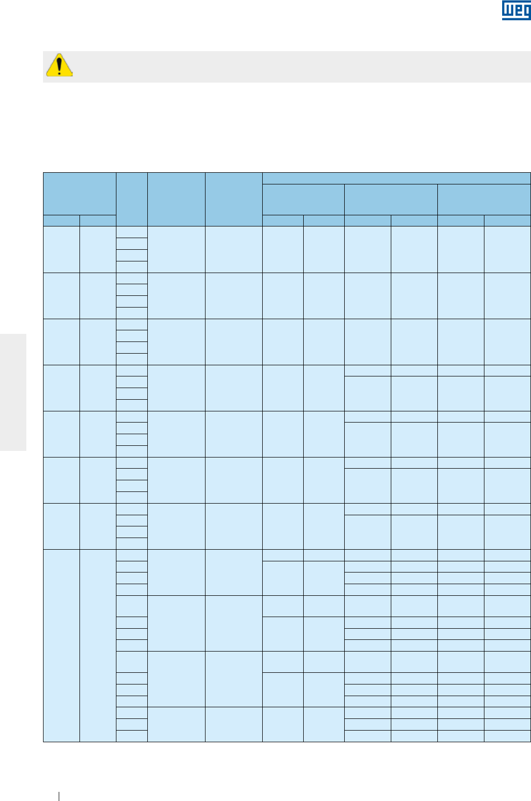
www.weg.net
Manual of Electric Motors100
ENGLISH
Excess grease causes bearing overheating, resulting in bearing failure.
8.2.1. Grease lubricated rolling bearings
Table 8.1 - Lubrication intervals for ball bearings
Frame Poles Bearing
designation
Amount of
grease (g)
Lubrication intervals (hours)
ODP
(Open Drip Proof)
W21 TEFC
(Totally Enclosed Fan
Cooled)
W22 TEFC
(Totally Enclosed Fan
Cooled)
IEC NEMA 50 Hz 60 Hz 50 Hz 60 Hz 50 Hz 60 Hz
90 143/5
2
6205 4 - - 20000 20000 25000 25000
4
6
8
100 -
2
6206 5 - - 20000 20000 25000 25000
4
6
8
112 182/4
2
6207/
6307 9 - - 20000 20000 25000 25000
4
6
8
132 213/5
2
6308 11 - -
20000 18400 25000 23200
4
20000 20000 25000 250006
8
160 254/6
2
6309 13 20000 20000
18100 15700 22000 20000
4
20000 20000 25000 250006
8
180 284/6
2
6311 18 20000 20000
13700 11500 17000 14000
4
20000 20000 25000 250006
8
200 324/6
2
6312 21 20000 20000
11900 9800 15000 12000
4
20000 20000 25000 250006
8
225
250
280
315
355
364/5
404/5
444/5
445/7
447/9
L447/9
504/5
5008
5010/11
586/7
588/9
2
6314 27
18000 14400 4500 3600 5000 4000
4
20000 20000
11600 9700 14000 12000
6 16400 14200 20000 17000
8 19700 17300 24000 20000
2
6316 34
14000 *Upon
request 3500 *Upon
request 4000 *Upon
request
4
20000 20000
10400 8500 13000 10000
6 14900 12800 18000 16000
8 18700 15900 20000 20000
2
6319 45
9600 *Upon
request 2400 *Upon
request 3000 *Upon
request
4
20000 20000
9000 7000 11000 8000
6 13000 11000 16000 13000
8 17400 14000 20000 17000
4
6322 60 20000 20000
7200 5100 9000 6000
6 10800 9200 13000 11000
8 15100 11800 19000 14000
The lubrication intervals specified in Table 8.1, Table 8.2, Table 8.3 and Table 8.4 consider an absolute
temperature on the bearing of 70 °C (up to frame size IEC 200 / NEMA 324/6) and 85 °C (for frame size IEC
225 / NEMA 364/5 and above), the motor running at rated speed, a motor mounted in horizontal position and
greased with Mobil Polyrex EM grease. Any variation of the parameters listed above must be evaluated.
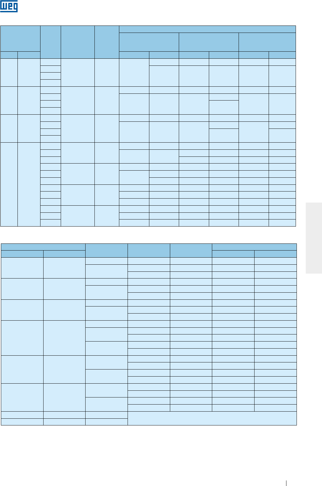
www.weg.net
Manual of Electric Motors 101
ENGLISH
Table 8.2 - Lubrication intervals for cylindrical roller bearings
Table 8.3 - Lubrication intervals for ball bearings - HGF line
Frame Poles Bearing
designation
Amount
of
grease
(g)
LUBRICATION INTERVALS (hours)
ODP
(Open Drip Proof)
W21 TEFC
(Totally Enclosed Fan
Cooled)
W22 TEFC
(Totally Enclosed Fan
Cooled)
IEC NEMA 50 Hz 60 Hz 50 Hz 60 Hz 50 Hz 60 Hz
160 254/6
2
NU309 13 20000
19600 13300 9800 16000 12000
4
20000 20000 20000 25000 250006
8
180 284/6
2
NU311 18
18400 12800 9200 6400 11000 8000
4
20000 20000 20000
19100
25000 250006 20000
8
200 324/6
2
NU312 21
15200 10200 7600 5100 9000 6000
4
20000 20000 20000
17200
25000
21000
620000 25000
8
225
250
280
315
355
364/5
404/5
444/5
445/7
447/9
L447/9
504/5
5008
5010/11
586/7
588/9
4
NU314 27
17800 14200 8900 7100 11000 9000
620000 20000 13100 11000 16000 13000
8 16900 15100 20000 19000
4
NU316 34
15200 12000 7600 6000 9000 7000
620000 19000 11600 9500 14000 12000
8 20000 15500 13800 19000 17000
4
NU319 45
12000 9400 6000 4700 7000 5000
6 19600 15200 9800 7600 12000 9000
8 20000 20000 13700 12200 17000 15000
4
NU322 60
8800 6600 4400 3300 5000 4000
6 15600 11800 7800 5900 9000 7000
8 20000 20000 11500 10700 14000 13000
Frame Poles Bearing
designation
Amount of
grease (g)
Lubrication intervals (hours)
IEC NEMA 50 Hz 60 Hz
315L/A/B and
315C/D/E
5006/7/8T and
5009/10/11T
2 6314 27 3100 2100
4 - 8 6320 50 4500 4500
6316 34 4500 4500
355L/A/B and
355C/D/E
5807/8/9T and
5810/11/12T
2 6314 27 3100 2100
4 - 8 6322 60 4500 4500
6319 45 4500 4500
400L/A/B and
400 C/D/E
6806/7/8T and
6809/10/11T
2 6315 30 2700 1800
4 - 8 6324 72 4500 4500
6319 45 4500 4500
450 7006/10
2 6220 31 2500 1400
46328 93 4500 3300
6322 60 4500 4500
6 - 8 6328 93 4500 4500
6322 60 4500 4500
500 8006/10
46330 104 4200 2800
6324 72 4500 4500
6 - 8 6330 104 4500 4500
6324 72 4500 4500
500 8006/10
46330 104 4200 2800
6324 72 4500 4500
6 - 8 6330 104 4500 4500
6324 72 4500 4500
560 8806/10 4 - 8 *Upon request
630 9606/10 4 - 8

www.weg.net
Manual of Electric Motors102
ENGLISH
For lubrication, use only manual grease gun.
Table 8.4 - Lubrication intervals for cylindrical roller bearings - HGF line
Frame Poles Bearing
designation
Amount of
grease (g)
Lubrication intervals (hours)
IEC NEMA 50 Hz 60 Hz
315L/A/B and
315C/D/E
5006/7/8 and
5009/10/11
4NU320 50 4300 2900
6 - 8 4500 4500
355L/A/B and
355C/D/E
5807/8/9 and
5810/11/12
4NU322 60 3500 2200
6 - 8 4500 4500
400L/A/B and
400C/D/E
6806/7/8 and
6809/10/11
4NU324 72 2900 1800
6 - 8 4500 4500
450 7006/10
4
NU328 93
2000 1400
6 4500 3200
8 4500 4500
500 8006/10
4
NU330 104
1700 1000
6 4100 2900
8 4500 4500
560 8806/10 4NU228 + 6228 75 2600 1600
6 - 8 106 4500 4500
630 9606/10
4
NU232 + 6232
92 1800 1000
6 120 4300 3100
8 140 4500 4500
For each increment of 15 ºC above the bearing temperature, the relubrication intervals given in the Table must
be halved. The relubrication interval of motors designed by the manufacturer for mounting in horizontal position,
but installed in vertical position (with WEG authorization), must be halved.
For special applications, such as: high and low temperatures, aggressive environments, driven by frequency
inverter (VFD - frequency inverter), etc., please contact WEG about the required amount of grease and the
relubrication intervals.
If Motors are provided with a spring device for grease removal, the grease excess must be removed by pulling
the rod and cleaning the spring until the spring does not remove more grease.
8.2.1.1. Motor without grease fitting
Motors without grease fittings must be lubricated in accordance with the existing Maintenance Plan. Motor
disassembly must be carried out as specified in Item 8.3. If motors are fitted with shielded bearings (for
example, ZZ, DDU, 2RS, VV), these bearings must be replaced at the end of the grease service life.
8.2.1.2. Motor with grease fitting
To lubricate the bearings with the motor stopped, proceed as follows:
g Before lubricating, clean the grease nipple and immediate vicinity thoroughly;
g Lift grease inlet protection;
g Remove the grease outlet plug;
g Pump in approximately half of the total grease indicated on the motor nameplate and run the motor for about
1 (one) minute at rated speed;
g Switch-off the motor and pump in the remaining grease;
g Lower again the grease inlet protection and reinstall the grease outlet protection.
To grease the motor while running, proceed as follows:
g Before lubricating, clean the grease nipple and immediate vicinity thoroughly;
g Pump the total grease indicated on the motor nameplate;
g Lower again the grease inlet protection.
8.2.1.3. Compatibility of the Mobil Polyrex EM grease with other greases
The Mobil Polyrex EM grease has a polyurea thickener and a mineral oil thus being compatible with greases
that contain:
g Lithium based thickener, lithium-based complex thickener, polyurea thickener and refined mineral oil;
g The used grease must have in its formulation corrosion and oxidation inhibitors.
In general terms, greases with the same type of soap are compatible to each other. However, depending on the
proportion of the mixture there may be incompatibility. In such a case, it is not recommended to mix different
types of greases without contacting the supplier or WEG beforehand.
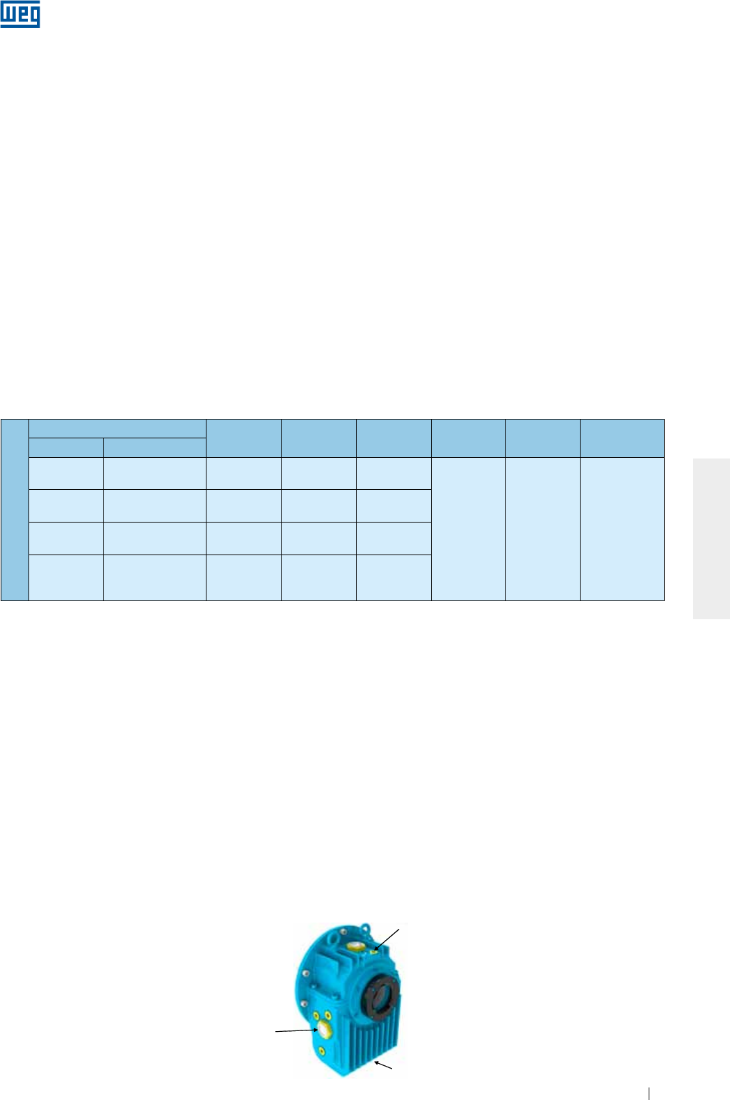
www.weg.net
Manual of Electric Motors 103
ENGLISH
Table 8.5 - Oil properties for HGF vertical mounted motors with high axial thrust
8.2.2. Oil lubricated bearings
To change the oil of oil lubricated motor proceed as follows:
g Switch-off the motor;
g Remove threaded oil drain plug;
g Open the valve and drain the oil;
g Close the drain vale again;
g Reinstall the threaded oil drain plug;
g Fill-up with the type and amount of oil as specified on the nameplate;
g Check oil level. The oil level is OK when the lubricant can be viewed approximately in the center of the sight
glass;
g Reinstall oil inlet plug;
g Check for oil leaks and ensure that all not used threaded plugs are closed with plugs.
The bearing lubricating oil must be replaced as specified on the nameplate or whenever changes in the oil
properties are noticed. The oil viscosity and pH must be checked periodically. The oil level must be checked
every day and must be kept in the center of the sight glass.
Please contact WEG, when oils with different viscosities should be used.
8.2.3. Oil mist lubricated bearings
Check the service conditions of the seals and if replacement is required use only original components. Clean
the seal components before assembly (bearing caps, end shields, etc.).
Apply joint sealant between the bearing caps and end shields. The joint sealant must be compatible with the
used lubricating oil. Connect the oil lubricant tubes (oil inlet and oil outlet tubes and motor drain tube), as shown
in Figure 6.12.
8.2.4. Sleeve bearings
The lubricating oil of sleeve bearings must be changed at the intervals specified in Table 8.6. To replace the oil,
proceed as follows:
g NDE-bearing: remove the protection plate from the fan cover;
g Drain the oil through the drain hole located at the bottom of the bearing (see Figure 8.1);
g Close the oil drain hole;
g Remove the oil inlet plug;
g Fill the sleeve bearing with the specified oil and with the amount of oil specified in;
g Check the oil level and ensure it is kept close to the center of the sight glass;
g Install the oil inlet plug;
g Check for oil leaks.
Note:
The HGF vertical mounted motors with high axial thrust are supplied with grease lubricated DE-bearings and with oil lubricated NDE-
bearings. The DE-bearings must be lubricated according to recommendations in item 8.2.1. Table 8.5 specifies the oil type and the
amount of oil required for this motor lubrication.
Mounting - high axial thrust
Frame Poles Bearing
designation Oil (liters) Interval (h) Lubricant Lubricant
specification
IEC NEMA
315L/A/B e
315C/D/E
5006/7/8T e
5009/10/11T 4 - 8 29320 20
8000
Renolin
DTA 40 /
SHC 629
ISO VG150
mineral oil with
antifoam and
antioxidant
additives
355L/A/B e
355C/D/E
5807/8/9T e
5810/11/12T 4 - 8 29320 26
400L/A/B e
400C/D/E
6806/7/8T e
6809/10/11T 4 - 8 29320 37
450 7006/10 4 - 8 29320 45
Oil sight glass
Oil inlet
Oil outlet
Figure 8.1 - Sleeve bearing
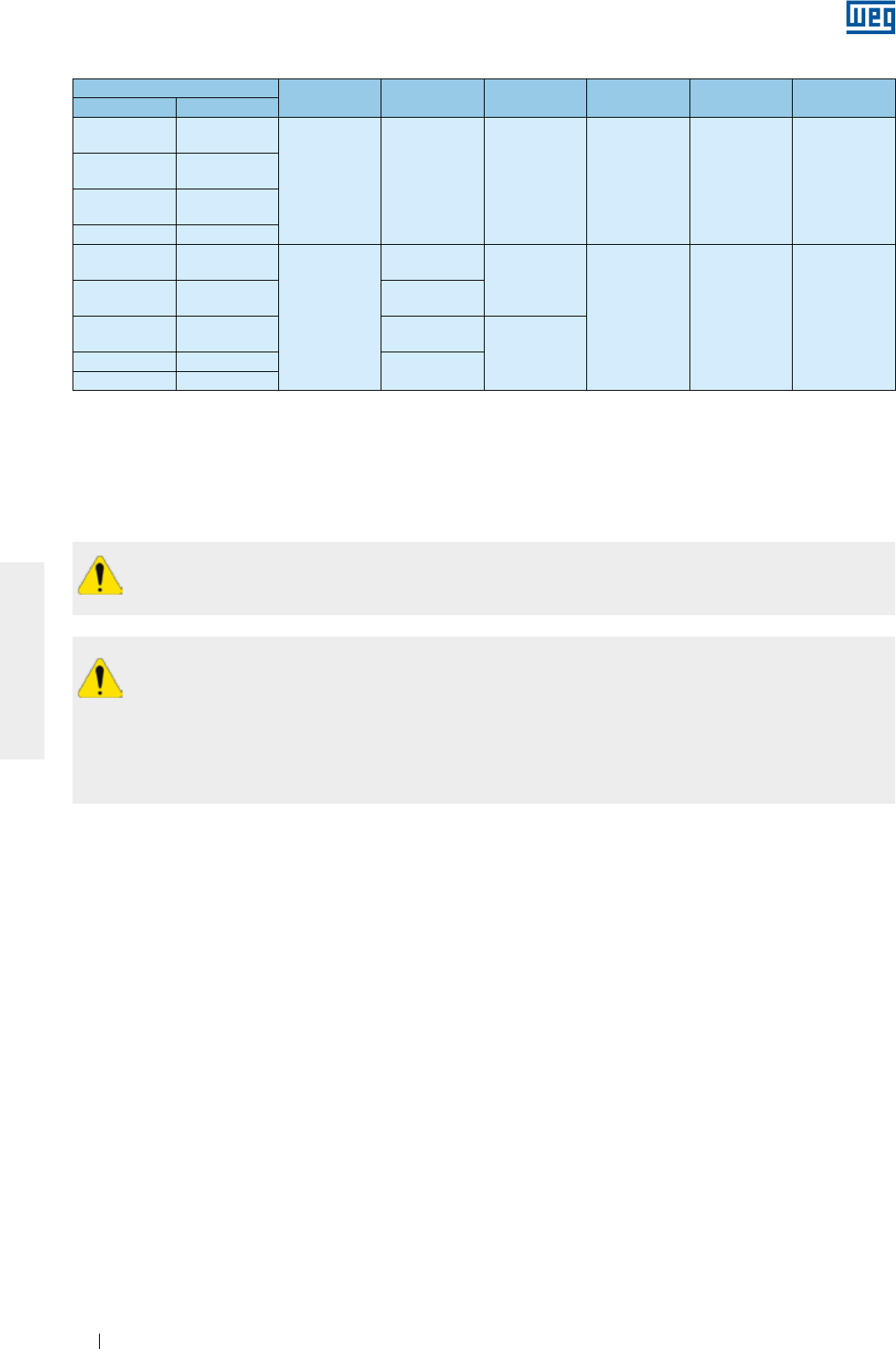
www.weg.net
Manual of Electric Motors104
ENGLISH
All repair services on motors should be always performed by qualified personnel and in accordance with
the applicable laws and regulations in each country. Always use proper tools and devices for motor
disassembly and assembly.
Disassembly and assembly services can be carried out only after the motor has been disconnected
from the power supply and is completely stopped.
Dangerous voltages may be present at the motor terminals inside the terminal box since capacitors can
retain electrical charge for long periods of time even when they are not connected directly to a power source or
when space heaters are connected to the motor or when the motor windings are used as space heaters.
Dangerous voltages may be present at the motor terminals when they are driven by frequency inverter even
when they are completely stopped.
Frame Poles Bearing
designation
Oil
(liters) Interval (h) Lubricant Lubricant
specification
IEC NEMA
315L/A/B and
315C/D/E
5006/7/8T and
5009/10/11T
2 9-80 2.8 8000 Renolin
DTA 10
ISO VG32
mineral oil with
antifoam and
antioxidant
additives
355L/A/B and
355C/D/E
5807/8/9T and
5810/11/12T
400L/A/B and
400C/D/E
6806/7/8 and
6809/10/11T
450 7006/10
315L/A/B and
315C/D/E
5006/7/8T and
5009/10/11T
4 - 8
9-90
2.8
8000 Renolin DTA 15
ISO VG46
mineral oil with
antifoam and
antioxidant
additives
355L/A/B and
355C/D/E
5807/8/9T and
5810/11/12T 9-100
400L/A/B and
400C/D/E
6806/7/8 and
6809/10/11T 11-110
4.7
450 7006/10 11-125
500 8006/10
The lubricating oil must be replaced as specified on the nameplate or whenever changes on the oil properties
are noticed. The oil viscosity and pH must be checked periodically. The oil level must be checked every day
and kept in the center of the sight glass.
Please contact WEG, when oils with different viscosities are to be used.
Record the installation conditions such as terminal connection diagram, alignment / leveling conditions before
starting the disassembly procedures. These records should be considered for later assembly.
Disassemble the motor carefully without causing scratches on machined surfaces or damaging the threads.
Assemble the motor on a flat surface ensuring a good support base. Footless motors must be fixed/locked on
the base to prevent accidents.
Handle the motor carefully to not damage the insulated components such as windings, insulated rolling
bearings, power cables etc..
Seal elements, such as joint seals and bearing seals should always be replaced when wear or damage is
noticed.
Motors with degree of protection higher than IP55 are supplied with joint and screw seal Loctite 5923 (Henkel)
Clean the components and apply a new coat of Loctite 5923 on the surfaces before assembly.
8.3. MOTOR ASSEMBLY AND DISASSEMBLY
Table 8.6 - Oil properties for sleeve bearings
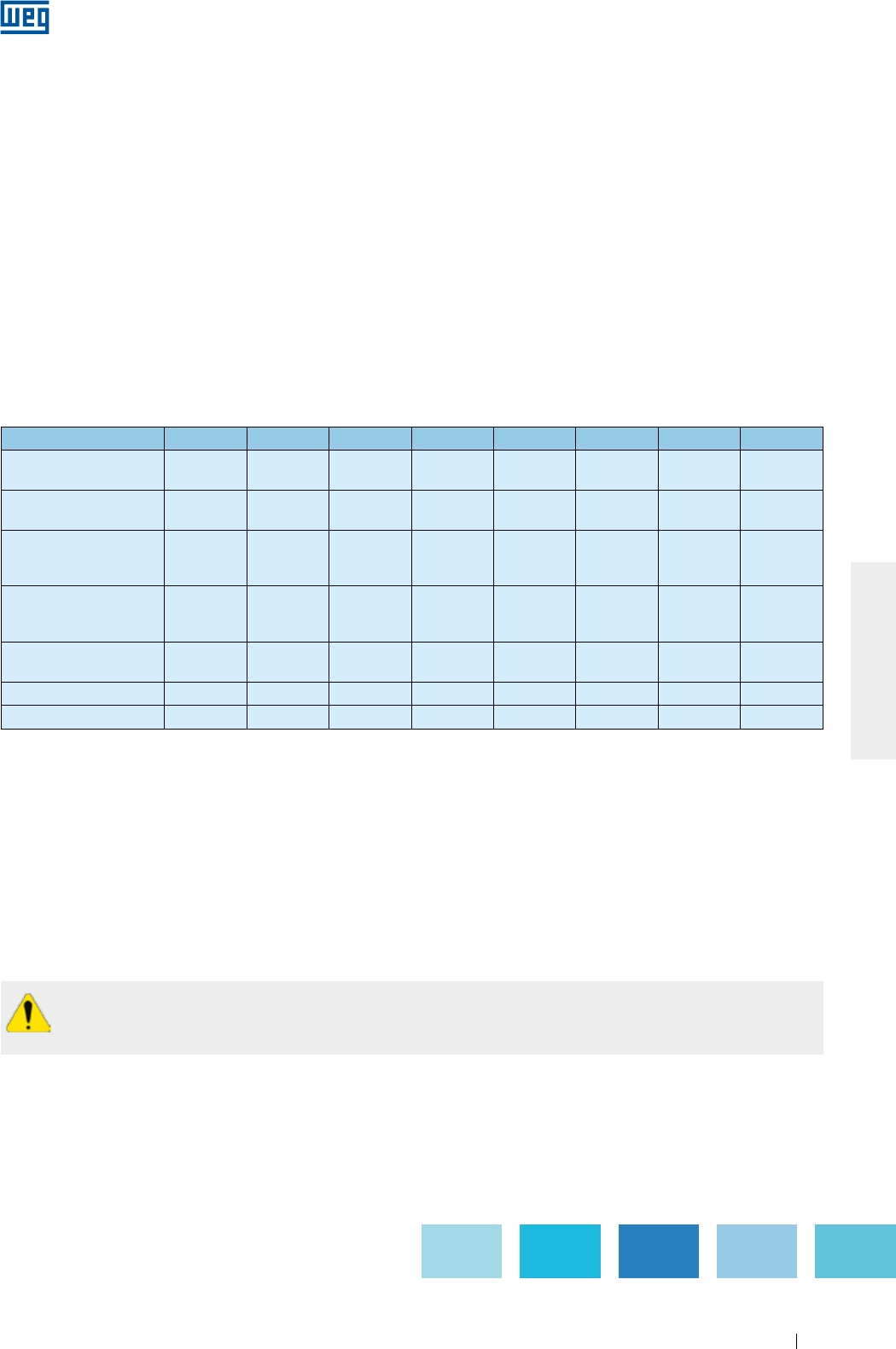
www.weg.net
Manual of Electric Motors 105
ENGLISH
To prevent electrical shock, discharge the motor terminals immediately before, and after each
measurement. If the motor is equipped with capacitors, these must be discharged before beginning any
repair.
8.3.1. Terminal box
Proceed as follows to remove the terminal box cover and to disconnect/connect the power supply cables and
the cables of the accessory devices:
g Ensure that during the screw removal the terminal box cover does not damage the components installed
inside the terminal box;
g If the terminal box cover is fitted with lifting eyebolt, lift the terminal box cover always by its lift eyebolt;
g If motors are supplied with terminal blocks, ensure the correct tightening torque on the motor terminals as
specified in Table 8.7;
g Ensure that the cables do not contact sharp edges;
g Ensure that the original IP degree of protection is not changed and is maintained as indicate on the motor
nameplate. The power supply cables and the control cables must always be fitted with components (cable
glands, conduits) that meet the applicable standards and regulations of each country;
g Ensure that the pressure relief device is in perfect operating condition, if provided. The seals in the terminal
box must be in perfect condition for reuse and must be reinstalled correctly to ensure the specified degree of
protection;
g Ensure the correct tightening torque for the securing bolts of the terminal box cover as specified in Table 8.7.
Table 8.7 - Tightening torque for the securing bolts [Nm]
Screw type and seal M4 M5 M6 M8 M10 M12 M16 M20
Hex bolt/hex socket bolt
(without seal) - 4 to 7 7 to 12 16 to 30 30 to 50 55 to 85 120 to 180 230 to 360
Combined slotted screw
(without seal) - 3 to 5 5 to 10 10 to 18 - - - -
Hex bolt/hex socket bolt
(with seal with metallic
stop/cord)
- - - 13 to 20 25 to 37 40 to 55 50 to 65 -
Combined slotted screw
(with flat seal 'and/or
mettallic stop/cord)
- 3 to 5 4 to 8 8 to 15 - - - -
Hex bolt/hex socket bolt
(with flat seal) - - - 8 to 15 18 to 30 25 to 40 35 to 50 -
Terminal blocks 1 to 1,5 1,5 to 4 3 to 6,5 6 to 9 10 to 18 15,5 to 30 30 to 50 -
Grounding terminals - 3 to 5 5 to 10 10 to 18 30 to 50 55 to 85 120 to 180 -
8.4. DRYING THE STATOR WINDING INSULATION
Dismantle the motor completely. Remove the end shields, the rotor with the shaft, the fan cover, the fan and the
terminal box before the wound stator with the frame is transferred to the oven for the drying process. Place the
wound stator in the oven heated to max. 120 °C for two hours. For larger motors a longer drying time may be
required. After the drying process has been concluded, allow the stator to cool to room temperature. Measure
the insulation resistance again as described in item 5.4. Repeat the stator drying process if the required
insulation resistance does not meet the values specified in Table 5.3. If the insulation resistance does not
improve despite several drying processes, evaluate the causes of the insulation resistance drop carefully and an
eventual replacement of the motor winding may be required. If in doubt contact WEG.
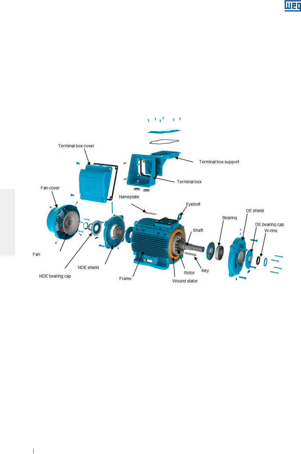
www.weg.net
Manual of Electric Motors106
ENGLISH
8.5. SPARE PARTS
When ordering spare parts, always provide complete motor designation, indicating the motor type, the code
number and the serial number, which are stated on the motor nameplate.
Spare parts must always be purchased from WEG authorized Service Centers. The use of non-original spare
parts can cause motor failure, performance drop and void the product warranty.
The spare parts must be stored in a clean, dry and properly ventilated room, with relative air humidity not
exceeding 60%, with ambient temperature between 5 °C and 40 °C, free of dust, vibrations, gases, corrosive
smokes and at constant temperature. The spare parts must be stored in their normal mounting position without
placing other components onto them.
Figure 8.2 - Exploded view of the components of a W22 motor

www.weg.net
Manual of Electric Motors 107
ENGLISH
9. ENVIRONMENTAL INFORMATION
9.1. PACKAGING
WEG electric motors are supplied in cardboard, plastic or wooden packaging. These materials can be recycled
and must be disposed according to the applicable laws and regulations in each country. All wood used in the
packaging of WEG motors come from the company reforestation program and is not submitted to any chemical
conservation treatment.
9.2. PRODUCT
Electric motors consist mainly of ferrous metals (steel plates and cast iron), non ferrous metals (copper and
aluminum) and plastic materials.
In general, electric motors have relatively long service live. However when they must be discarded, WEG
recommends to dismantle the motor, sort the different materials and send them for recycling.
No-recyclable materials should be disposed of at industrial landfills according to the applicable environmental
laws and regulations in each country, or co-processed in cement kilns or incinerated.
The recycling service providers, the disposal in industrial landfills, the waste co-processing or the incineration
process must be properly authorized by the state environment agency to carry out these activities.
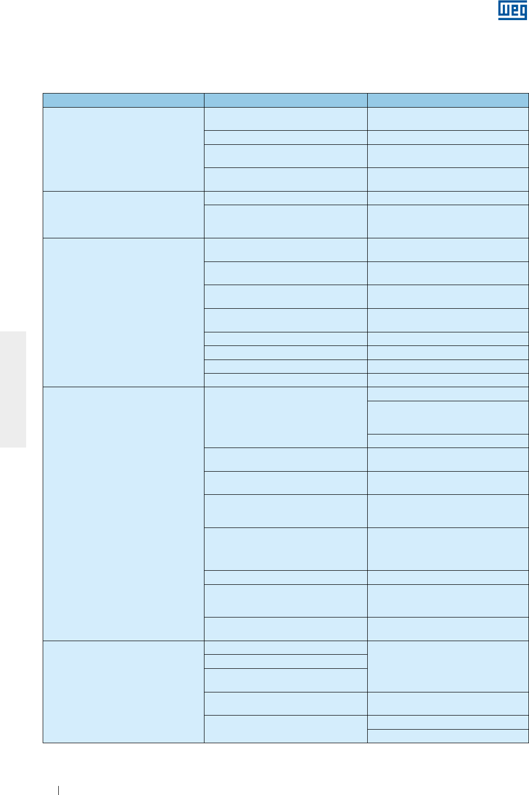
www.weg.net
Manual of Electric Motors108
ENGLISH
Problem Possible cause Corrective action
Motor does not start, neither coupled nor
decoupled
Power cables are interrupted Check the control panel and the motor
power supply cables
Blown fuses Replace blown fuses
Wrong motor connection Correct the motor connection according to
connection diagram
Locked rotor Check motor shaft to ensure that it rotates
freely
The motor starts at no-load, but fails when
load is applied. It starts very slowly and
does not reach the rated speed
Load toque is too high during start-up Do not start the motor on load
Too high voltage drop in the power cables
Check the installation dimensioning
(transformer, cable cross section, relays,
circuit breakers, etc.)
Abnormal/excessive noise
Defective transmission component or
defective driven machine
Check the transmission force, the coupling
and the alignment
Misaligned / unleveled base Align / level the motor with the driven
machine
Unbalanced components or unbalanced
driven machine Balance the machine set again
Different balancing methods used for motor
and coupling balancing (halve key, full key) Balance the motor again
Wrong motor direction of rotation Reverse the direction of rotation
Loose bolts Retighten the bolts
Foundation resonance Check the foundation design
Damaged bearings Replace the bearings
Motor overheating
Insufficient cooling
Clean air inlet and outlet and cooling fins
Check the minimum required distance
between the fan cover and nearest walls.
See item 7
Check air temperature at inlet
Overload Measure motor current, evaluate motor
application and if required, reduce the load
Number of starts per hour is too high or the
load inertia moment is too high Reduce the number of starts per hour
Power supply voltage too high
Check the motor power supply voltage.
Power supply voltage must not exceed the
tolerance specified in item 7.2
Power supply voltage too low
Check the motor power supply voltage and
the voltage drop. Power supply voltage
must not exceed the tolerance specified in
item 7.2
Interrupted power supply Check the connection of the power cables
Voltage unbalance at the motor terminals
Check for blown fuses, wrong commands,
voltage unbalance in the power line, phase
fault or interrupted power cables
Direction of rotation is not compatible with
the unidirectional fan
Check if the direction of rotation matches
the rotation arrow indicated on end shield
Bearing overheating
Excessive grease/oil Clean the bearing and lubricate it
according to the provided
recommendations
Grease/oil aging
The used grease/oil does not matches the
specified one
Lack of grease/oil Lubricate the bearing according to the
provided recommendations
Excessive axial or radial forces due to
the belt tension
Reduce the belt tension
Reduce the load applied to the motor
10. TROUBLESHOOTING CHART X SOLUTIONS
This troubleshooting chart provides a basic list of problems that may occur during motor operation, possible
causes and recommended corrective actions. In case of doubts, please contact WEG Service Center.

www.weg.net
Manual of Electric Motors 109
ENGLISH
11. WARRANTY TERM
WEG Equipamentos Elétricos S/A, Motors Unit (“WEG”), offers warranty against defects in workmanship and
materials for its products for a period of 18 months from the invoice date issued by the factory or distributor/
dealer, limited to 24 months from the date of manufacture.
Motors of the HGF Line are covered for a period of 12 months from the invoice date issued by the factory or
distributor / dealer, limited to 18 months from the date of manufacture.
The paragraphs above contain the legal warranty periods.
If a warranty period is defined in a different way in the commercial/technical proposal of a particular sale, that
will supersede the time limits set out above.
The warranty periods above are independent of the product installation date and the startup.
If any defect or abnormal occurrence is detected during machine operation, the customer must immediately
notify WEG in writing about the occurred defect, and make the product available for WEG or its Authorized
Service Center for the period required to identify the cause of the defect, check the warranty coverage, and
perform the proper repairs.
In order for the warranty to be valid, the customer must be sure to follow the requirements of WEG’s technical
documents, especially those set out in the product Installation, Operation and Maintenance Manual, as well as
the applicable standards and regulations in force in each country.
Defects arising from the inappropriate or negligent use, operation, and/or installation of the equipment,
non-execution of regular preventive maintenance, as well as defects resulting from external factors or
equipment and components not supplied by WEG, will not be covered by the warranty.
The warranty will not apply if the customer at its own discretion makes repairs and/or modifications to the
equipment without prior written consent from WEG.
The warranty will not cover equipment, components, parts and materials whose lifetime is usually shorter than
the warranty period. It will not cover defects and/or problems resulting from force majeure or other causes not
imputable to WEG, such as, but not limited to: incorrect or incomplete specifications or data supplied by the
customer; transportation, storage, handling, installation, operation and maintenance not complying with the
provided instructions; accidents; defects in the construction works; use in applications and/or environments for
which the machine was not designed; equipment and/or components not included in the scope of WEG
supply. The warranty does not include disassembly services at the buyer’s premises, product transportation
costs and travel, lodging and meal expenses for the technical staff of the Service Centers, when requested by
the customer.
The services under warranty will be provided exclusively at WEG authorized Service Centers or at one of its
manufacturing plants. Under no circumstances will the warranty services extend the equipment warranty
period.
WEG’s Civil Liability is limited to the supplied product; WEG will not be liable for indirect or consequential
damages, such as losses of profit and revenue losses and alike which may arise from the contract signed
between the parties.

www.weg.net
Manual of Electric Motors110
ENGLISH
12. EC DECLARATION OF CONFORMITY
WEG Equipamentos Elétricos S/A
Av. Prefeito Waldemar Grubba, 3000
89256-900 - Jaraguá do Sul – SC – Brazil,
and its authorised representative established in the European Community,
WEGeuro – Industria Electrica SA
Contact person: Luís Filipe Oliveira Silva Castro Araújo
Rua Eng Frederico Ulrich, Apartado 6074
4476-908 – Maia – Porto – Portugal
hereby declare that the products:
WEG induction motors and components for using in these motors:
Three-phase
IEC frames 63 to 630
Nema frames 42, 48, 56 and 143 to 9610
……………
Single-phase
IEC frames 63 to 132
Nema frames 42, 48, 56 and 143 to 215
……………
when installed, maintained and used in applications for which they were designed, and in compliance with the relevant
installation standards and manufacturer’s instructions, comply with the requirements of the following European Directives
and standards where applicable:
Directives:
Low Voltage Directive 2006/95/EC*
Regulation (EC) No 640/2009*
Directive 2009/125/EC*
Machinery Directive 2006/42/EC**
EMC Directive 2004/108/EC (inductions motors are considered inherently benign in terms of electromagnetic
compatibility)
Standards:
EN 60034-1:2010/ EN 60034-2-1:2007/EN 60034-5:2001/A1:2007/ EN 60034-6:1993/ EN 60034-7:1993/A1:2001/
EN 60034-8:2007/ EN 60034-9:2005/A1:2007/ EN 60034-11:2004/ EN 60034-12:2002/A1:2007/
EN 60034-14:2004/A1:2007/ EN 60034-30:2009, EN 60204-1:2006/AC:2010 and EN 60204-11:2000/AC:2010
CE marking in: 1996
* Electric motors designed for use with a voltage rating higher than 1,000 V are not considered under the scope.
** Low voltage electric motors are not considered under the scope and electric motors designed for use with a voltage
rating higher than 1,000 V are considered partly completed machinery and are supplied with a
Declaration of Incorporation:
The products above cannot be put into service until the machinery into which they have been incorporated has been
declared in conformity with the Machinery Directive.
A Technical Documentation for the products above is compiled in accordance with part B of annex VII of Machinery
Directive 2006/42/EC.
We undertake to transmit, in response to a reasoned request by the national authorities, relevant information on the partly
completed machinery identified above through WEG authorised representative established in the European Community.
The method of transmission shall be electronic or physical method and shall be without prejudice to the intellectual
property rights of the manufacturer.
Milton Oscar Castella
Engineering Director
Jaraguá do Sul, April 8th, 2013

www.weg.net
Motores Eléctricos112
MANUAL GENERAL DE INSTALACIÓN, OPERACIÓN Y
MANTENIMIENTO DE MOTORES ELÉCTRICOS
Este manual presenta informaciones referentes a los motores eléctricos WEG de inducción
con rotor de jaula, con rotor de imanes permanentes o híbridos, de baja y alta tensión, en las
carcasas IEC 56 a 630 y NEMA 42 a 9606/10.
Las líneas listadas abajo poseen informaciones adicionales, encontradas en manuales
específicos:
g Motores para extracción de humo (Smoke Extraction Motor);
g Motores con freno electromagnético;
g Motores para Áreas Clasificadas.
Estos productos están de acuerdo con las siguientes normas, cuando son aplicables:
g NBR 17094-1: Máquinas Eléctricas Giratorias - Motores de Inducción - Parte 1: trifásicos.
g NBR 17094-2: Máquinas Eléctricas Giratorias - Motores de Inducción - Parte 2: monofásicos.
g IEC 60034-1: Rotating Electrical Machines - Part 1: Rating and Performance
g NEMA MG 1: Motors and Generators.
g CSA C 22.2 N°100: Motors and Generators.
g UL 1004-1: Rotating Electrical Machines - General Requirements.
En caso de dudas sobre la aplicabilidad de este material, contacte a WEG.

www.weg.net
Motores Eléctricos 113
ESPAÑOL
INDICE
1. DEFINICIONES 115
2. RECOMENDACIONES INICIALES 116
2.1. SENÃL DE ADVERTENCIA .............................................................................................................116
2.2. VERIFICACION EN LA RECEPCION..............................................................................................116
2.3. PLACAS DE IDENTIFICACION .......................................................................................................117
3. SEGURIDAD 120
4. MANIPULACION Y TRANSPORTE 121
4.1. IZAMIENTO ..................................................................................................................................... 121
4.1.1. Motores horizontales con un ojal de izamiento ................................................................ 122
4.1.2. Motores horizontales con dos o más ojales de izamiento .............................................. 122
4.1.3. Motores verticales ................................................................................................................ 123
4.1.3.1. Procedimiento para colocación de motores W22 en posición vertical ....................... 124
4.1.3.2. Procedimiento para colocación de motores HGF en posición vertical ...................... 125
4.2. PROCEDIMIENTO PARA VIRADA DE MOTORES W22 VERTICALES ....................................... 126
5. ALMACENADO 128
5.1. SUPERFICIES MECANIZADAS EXPUESTAS ............................................................................... 128
5.2. APILAMIENTO ................................................................................................................................ 128
5.3. COJINETES ..................................................................................................................................... 129
5.3.1. Cojinetes de rodamiento lubricados a grasa .................................................................... 129
5.3.2. Cojinetes de rodamiento con lubricación a aceite .......................................................... 129
5.3.3. Cojinetes de rodamiento con lubricación de tipo Oil Mist .............................................. 130
5.3.4. Cojinetes de deslizamiento ................................................................................................. 130
5.4. RESISTENCIA DE AISLAMIENTO ................................................................................................. 130
5.4.1. Procedimiento para medición de la resistencia de aislamiento ..................................... 130
6. INSTALACION 133
6.1. CIMIENTOS PARA EL MOTOR ...................................................................................................... 134
6.2. FIJACION DEL MOTOR ................................................................................................................. 136
6.2.1. Fijación por las patas ........................................................................................................... 136
6.2.2. Fijación por brida ................................................................................................................. 137
6.2.3. Fijación por pad .................................................................................................................... 137
6.3. BALANCEO ..................................................................................................................................... 138
6.4. ACOPLAMIENTOS ......................................................................................................................... 138
6.4.1. Acoplamiento directo ........................................................................................................... 138
6.4.2. Acoplamiento por engranaje .............................................................................................. 138
6.4.3. Acoplamiento por poleas y correas ................................................................................... 138
6.4.4. Acoplamiento de motores equipados con cojinetes de deslizamiento......................... 138
6.5. NIVELACION ................................................................................................................................... 139
6.6. ALINEAMIENTO.............................................................................................................................. 139

www.weg.net
Motores Eléctricos114
ESPAÑOL
6.7. CONEXION DE MOTORES LUBRICADOS A ACEITE O DE TIPO OIL MIST ............................. 140
6.8. CONEXION DEL SISTEMA DE REFRIGERACION A AGUA ........................................................ 140
6.9. CONEXION ELECTRICA ................................................................................................................ 140
6.10. CONEXION DE LOS DISPOSITIVOS DE PROTECCION TERMICA .......................................... 143
6.11. TERMORESISTORES (PT-100) .................................................................................................... 144
6.12. CONEXION DE LAS RESISTENCIAS DE CALDEO .................................................................... 146
6.13. METODOS DE PARTIDA .............................................................................................................. 146
6.14. MOTORES ALIMENTADOS POR CONVERTIDOR DE FRECUENCIA ...................................... 147
6.14.1. Uso de filtros (dV/dt) ........................................................................................................... 147
6.14.1.1. Motor con alambre circular esmaltado ......................................................................... 147
6.14.1.2. Motor con bobina preformada ....................................................................................... 148
6.14.2. Aislamiento de los cojinetes ............................................................................................. 148
6.14.3. Frecuencia de conmutación .............................................................................................. 148
6.14.4. Límite de la rotación mecánica ......................................................................................... 148
7. OPERACION 150
7.1. PARTIDA DEL MOTOR ................................................................................................................... 150
7.2. CONDICIONES DE OPERACION .................................................................................................. 152
7.2.1. LÍMITES DE LA SEVERIDAD DE VIBRACIÓN ........................................................................... 153
8. MANTENIMIENTO 154
8.1. INSPECCION GENERAL ................................................................................................................ 154
8.2. LUBRICACION ................................................................................................................................ 154
8.2.1. Cojinetes de rodamiento lubricados a grasa .................................................................... 155
8.2.1.1. Motores sin grasera ........................................................................................................... 157
8.2.1.2. Motores con grasera ......................................................................................................... 157
8.2.1.3. Compatibilidad de la grasa Mobil Polyrex EM con otras grasas................................. 157
8.2.2. Cojinetes de rodamiento lubricados a aceite ................................................................... 158
8.2.3. Cojinetes de rodamiento con lubricación de tipo Oil Mist ............................................. 158
8.2.4. Cojinetes de deslizamiento ................................................................................................. 158
8.3. DESMONTAJE Y MONTAJE .......................................................................................................... 159
8.3.1. Caja de conexión .................................................................................................................. 160
8.4. PROCEDIMIENTO PARA ADECUACION DE LA RESISTENCIA DE AISLAMIENTO ................ 160
8.5. PARTES Y PIEZAS ......................................................................................................................... 161
9. INFORMACIONES AMBIENTALES 162
9.1. EMBALAGEM .................................................................................................................................. 162
9.2. PRODUCTO .................................................................................................................................... 162
10. PROBLEMAS Y SOLUCIONES 163
11. TERMINO DE GARANTIA 164
12. DECLARACION DE CONFORMIDAD CE 165

www.weg.net
Motores Eléctricos 115
ESPAÑOL
1. DEFINICIONES
Balanceo: procedimiento por el cual la distribución de masa de un cuerpo es verificada y, si es necesario,
ajustada para garantizar que el desbalance residual o las vibraciones y fuerzas en los cojinetes en la frecuencia
de rotación mecánica estén dentro de los límites especificados en las normas internacionales.
Grado de balanceo: indica la amplitud de pico de la velocidad de vibración, expresada en mm/s, de un rotor
girando libre en el espacio y es producto de un desbalance específico y la velocidad angular del rotor a la
velocidad máxima de operación.
Parte puesta a tierra: partes metálicas eléctricamente conectadas al sistema de puesta a tierra.
Parte viva: conductor o parte conductora destinada a ser energizada en condiciones normales de uso,
incluyendo el conductor neutro.
Personal autorizado: trabajador que tiene anuencia formal de la empresa.
Personal capacitado: trabajador que atienda las siguientes condiciones, simultaneamente:
g Reciba capacitación bajo orientación y responsabilidad de profesional habilitado y autorizado;
g Bajo responsabilidad de profesional habilitado y autorizado.
Nota: La capacitación sólo es válida para la empresa que lo capacitó y en las condiciones establecidas por el profesional habilitado y
autorizado responsable por la capacitación.
Personal habilitado: trabajador previamente calificado y con registro en el consejo de clase competente.
Personal calificado: trabajador que compruebe conclusión de curso específico en el área eléctrica por el
sistema oficial de enseñanza.
www.weg.net
Motores Eléctricos116
ESPAÑOL
2. RECOMENDACIONES INICIALES
Los motores eléctricos poseen circuitos energizados, componentes giratorios y superficies
calientes, durante su operación normal, que pueden causar daños personales. De esta forma,
todas las actividades relacionadas a su transporte, almacenado, instalación, operación y
mantenimiento deben ser realizadas por personal capacitado.
Deben ser observadas las normas y procedimientos vigentes en el país de instalación.
La no observación de las instrucciones indicadas en este manual y demás referencias en el sitio web:
www.weg.net puede resultar en serios daños personales y materiales y anular la garantía del producto.
La correcta definición de las características del ambiente y de la aplicación es de responsabilidad
del usuario.
Durante el período de garantía del motor, los servicios de reparación, revisión y recuperación deben
ser realizadas por Asistentes Técnicos autorizados WEG para continuidad del término de garantía.
En este manual no son presentadas todas las informaciones detalladas sobre posibles variantes constructivas
ni considerados todos los casos de montaje, operación o mantenimiento. Este documento contiene
informaciones necesarias para que las personas capacitadas puedan ejecutar el servicio. Las imágenes
presentadas son meramente ilustrativas.
Para motores utilizados para extracción de humo (Smoke Extraction Motors), consulte también las
instrucciones del manual 50026367 (inglés) disponible en el sitio web www.weg.net.
Para operación de motores con freno, consultar las informaciones del manual del motofreno WEG 50000701
(portugués) / 50006742 (inglés) o motofreno Intorq 50021505 (portugués) / 50021973 (inglés) disponibles en el
sitio web www.weg.net.
Para informaciones sobre cargas radiales y axiales admisibles en el eje consultar el catálogo técnico del
producto.
2.1. SENÃL DE ADVERTENCIA
Advertencia sobre seguridad y garantía.
2.2. VERIFICACION EN LA RECEPCION
Todos los motores son testeados durante el proceso de fabricación.
En la recepción del motor, verifique si ocurrieron daños durante el transporte. Ante la ocurrencia de cualquier
daño, regístrelo por escrito junto al agente transportador, y comuníquelo inmediatamente a la compañía
aseguradora y a WEG. La no comunicación puede resultar en la cancelación de la garantía.
Se debe realizar una inspección completa en el producto:
g Verifique si los datos contenidos en la placa de identificación están de acuerdo con el pedido de compra;
g Remueva los dispositivos de trabado del eje (en caso que existan) y gire manualmente el eje para verificar si
el mismo gira libremente;
g Asegúrese que el motor no haya sido expuesto a polvareda y humedad excesiva durante el transporte.
No remueva la grasa de protección de la punta del eje, ni los tapones que cierran los agujeros de la caja de
conexión, si existen. Estos ítems de protección deben ser mantenidos hasta que la instalación completa sea
concluída.
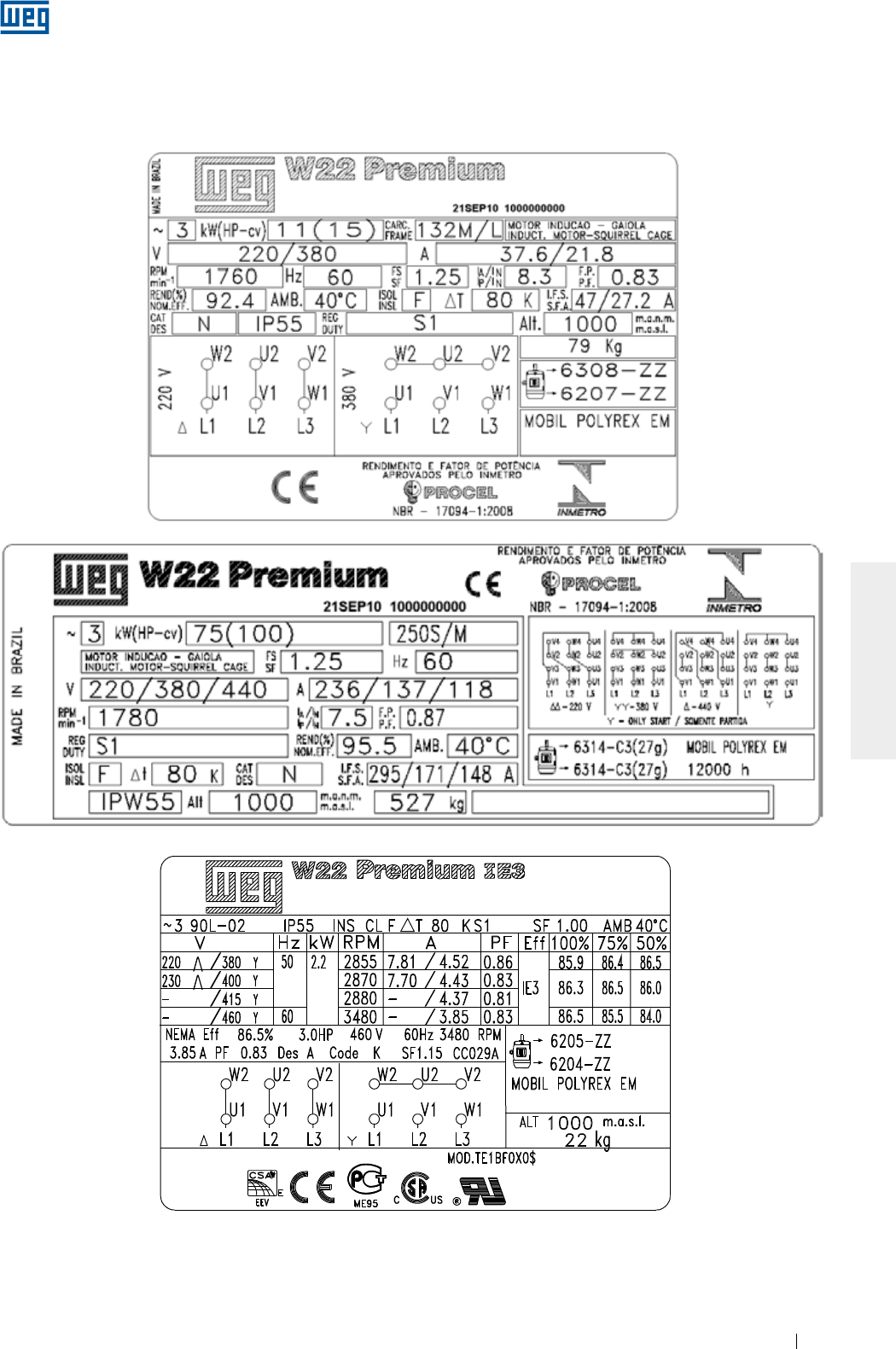
www.weg.net
Motores Eléctricos 117
ESPAÑOL
Figura 2.1 - Placa de identificación de motores IEC
2.3. PLACAS DE IDENTIFICACION
La placa de identificación contiene las informaciones que describen las características constructivas y el
desempeño del motor. En la Figura 2.1 y Figura 2.2 son presentados ejemplos de diseños de placas de
identificación.

www.weg.net
Motores Eléctricos118
ESPAÑOL
Figura 2.1 - Placa de identificación de motores IEC

www.weg.net
Motores Eléctricos 119
ESPAÑOL
Figura 2.2 - Placa de identificación de motores NEMA
www.weg.net
Motores Eléctricos120
ESPAÑOL
Los motores eléctricos poseen circuitos energizados, componentes giratorios y superficies
calientes, durante su operación normal, que pueden causar daños personales. De esta forma,
todas las actividades relacionadas a su transporte, almacenado, instalación, operación y
mantenimiento deben ser realizadas por personal capacitado.
3. SEGURIDAD
Durante la instalación y mantenimiento, los motores deben estar desconectados de la red,
completamente parados y deben ser tomados cuidados adicionales para evitar partidas
accidentales.
Los profesionales que trabajan en instalaciones eléctricas, sea en el montaje, en la operación o en
el mantenimiento, deben utilizar herramientas apropiadas y ser instruidos sobre la aplicación de las
normas y prescripciones de seguridad, inclusive sobre el uso de Equipamientos de Protección
Individual (EPI), los que deben ser cuidadosamente observados.
Deben ser seguidas las instrucciones sobre seguridad, instalación, mantenimiento e inspección de acuerdo
con las normas vigentes en cada país.
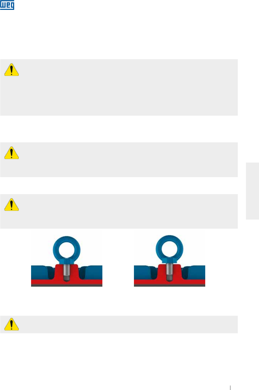
www.weg.net
Motores Eléctricos 121
ESPAÑOL
Figura 4.2 - Manera incorrecta de fijación
del ojal de izamiento
Figura 4.1 - Manera correcta de fijación
del ojal de izamiento
4. MANIPULACION Y TRANSPORTE
No utilice los ojales de izamiento para suspender el motor en conjunto con otros equipamientos,
como por ejemplo: bases, poleas, ventiladores, bombas, reductores, etc..
No deben ser utilizados ojales damnificados, por ejemplo, con rajaduras, deformaciones, etc. Verificar sus
condiciones antes de utilizarlos.
Los ojales de izamiento en componentes como tapas, kit de ventilación forzada, entre otros, deben ser
utilizados solamente para el izamiento de estos componentes de manera aislada, nunca del motor
completo.
Los dispositivos de trabado del eje (utilizados para protección durante el transporte), en motores
con rodamientos de rodillos o contacto angular, deben ser utilizados para todo y cualquier
transporte del motor, aunque eso requiera el desplazamiento de la máquina accionada.
Todos los motores HGF, independientemente del tipo de cojinete, deben tener su rotor trabado para
transporte.
Antes de iniciar cualquier proceso de izamiento, asegúrese de que los ojales estén adecuadamente
fijados, totalmente atornillados y con su base en contacto con la superficie a ser izada, conforme
Figura 4.1. La Figura 4.2 ejemplifica el uso incorrecto.
Asegúrese de que el equipamiento utilizado en el izamiento y sus dimensiones sean adecuados al tamaño
del ojal y de la masa del motor.
El centro de gravedad de los motores varía en función de la potencia y los accesorios instalados.
Respete los ángulos máximos, durante el izamiento, informados en los subtópicos a seguir.
Los motores embalados individualmente no deben ser izados por el eje o por el embalaje, sino por el(los)
ojal(es) de izamiento (cuando existan) y con dispositivos adecuados. Los ojales de izamiento son
dimensionados para soportar tan solo la masa del motor indicada en la placa de identificación. Los motores
suministrados en palés deben ser izados por la base de palé.
El embalaje no debe ser tumbado bajo ninguna circunstancia.
Todo el movimiento debe ser realizado de forma suave, sin impactos, en caso contrario los rodamientos
pueden ser dañados, así como los ojales ser expuestos a esfuerzos excesivos, pudiendo provocar el
rompimiento de los mismos.
4.1. IZAMIENTO
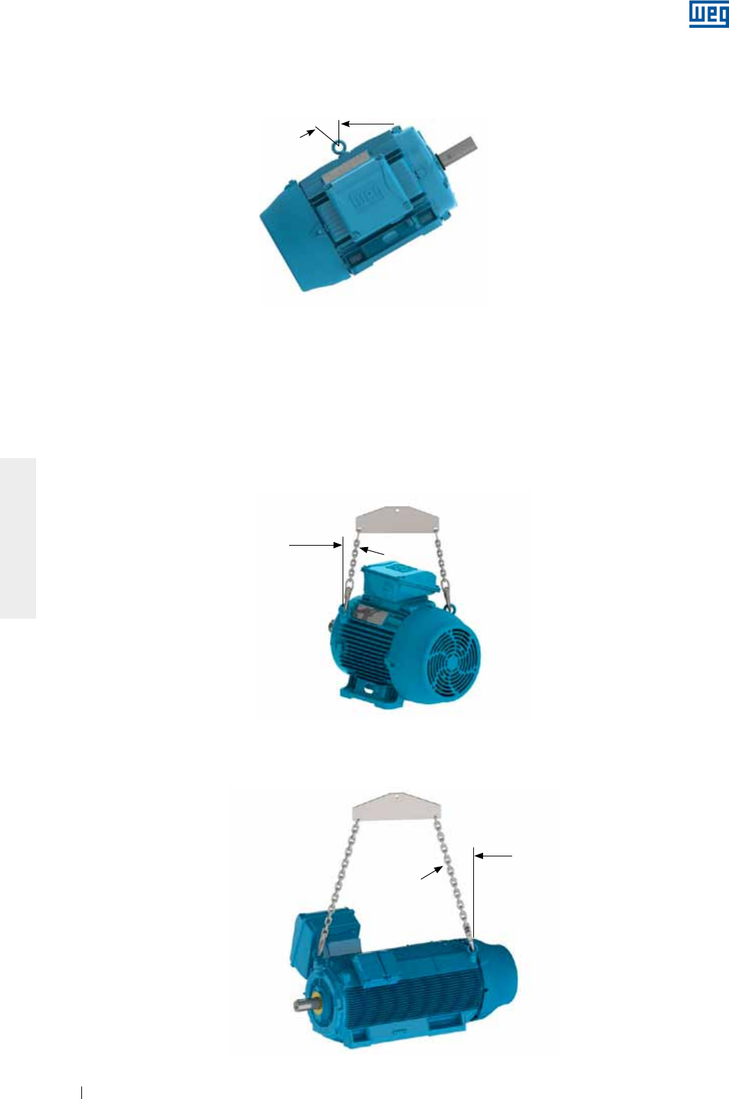
www.weg.net
Motores Eléctricos122
ESPAÑOL
4.1.1. Motores horizontales con un ojal de izamiento
Para motores con un ojal de izamiento, el ángulo máximo resultante durante el proceso de izamiento no podrá
exceder 30° en relación al eje vertical, conforme Figura 4.3.
Figura 4.3 - Ángulo máximo resultante para motores con un ojal de izamiento
4.1.2. Motores horizontales con dos o más ojales de izamiento
Para motores que poseen dos o más ojales para el izamiento, todos los ojales suministrados deben ser
utilizados simultáneamente para el izamiento.
Existen dos disposiciones de ojales posibles (verticales e inclinados), conforme son presentadas a seguir:
g Motores con ojales verticales, conforme Figura 4.4, el ángulo máximo resultante debe ser de 45° en relación
al eje vertical. Se recomienda la utilización de una barra separadora (spreader bar), para mantener el
elemento de izamiento (corriente o cable) en el eje vertical y evitar daños a la superficie del motor.
Figura 4.4 - Ángulo máximo resultante para motores con dos o más ojales de izamiento
45° Máx.
Para motores HGF, conforme Figura 4.5, el ángulo máximo resultante debe ser de 30° en relación al eje
vertical;
Figura 4.5 - Ángulo máximo resultante para motores HGF horizontales
30° Máx.
30° Max.

www.weg.net
Motores Eléctricos 123
ESPAÑOL
g Motores con ojales inclinados, conforme Figura 4.6, es necesaria la utilización de una barra separadora
(spreader bar), para mantener el elemento de izamiento (corriente, cable, etc.) en el eje vertical y así también
evitar daños a la superficie del motor.
Figura 4.6 - Uso de barra separadora en el izamiento
4.1.3. Motores verticales
Para motores verticales, conforme Figura 4.7, es necesaria la utilización de una barra separadora (spreader bar),
para mantener el elemento de izamiento (corriente, cable) en el eje vertical y así también evitar daños a la
superficie del motor.
Figura 4.7 - Izamiento de motores verticales
Utilice siempre los ojales que están dispuestos en la parte superior del motor en relación a la
posición de montaje y diametralmente opuestos. Ver Figura 4.8.
Figura 4.8 - Izamiento de motores HGF
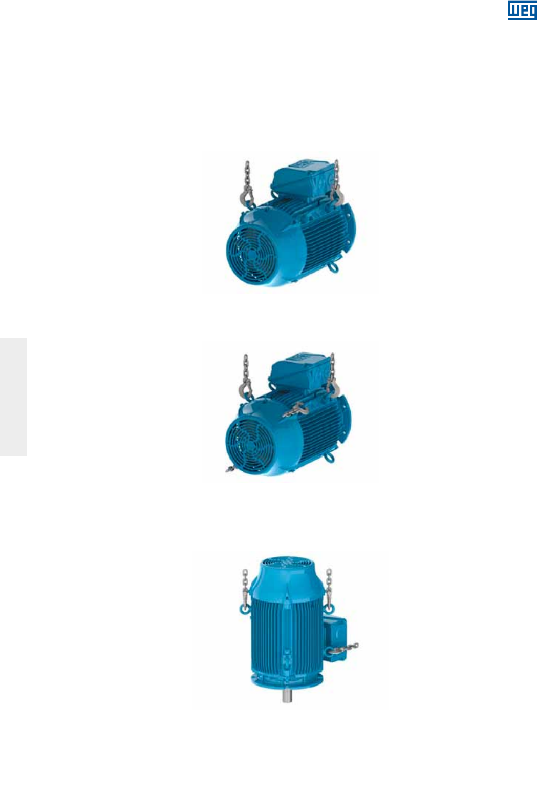
www.weg.net
Motores Eléctricos124
ESPAÑOL
4.1.3.1. Procedimiento para colocación de motores W22 en posición vertical
De forma general, por cuestiones de seguridad durante el transporte, los motores verticales son embalados y
suministrados en la posición horizontal.
Para la colocación de motores W22 con ojales inclinados (ver Figura 4.6) en la vertical, deben ser seguidos los
pasos abajo descritos:
1. Asegúrese de que los ojales están adecuadamente fijos, conforme Figura 4.1;
2. Remover el motor del embalaje, utilizando los ojales superiores, conforme Figura 4.9;
Figura 4.9 - Remoción del motor del embalaje
3. Instalar el segundo par de ojales, conforme Figura 4.10;
Figura 4.10 - Instalación del segundo par de ojales
4. Reducir la carga sobre el primer par de ojales para iniciar a rotación del motor, conforme Figura 4.11.
Este procedimiento debe ser realizado de forma lenta y cautelosa.
Figura 4.11 - Resultado final: motor posicionado de forma vertical

www.weg.net
Motores Eléctricos 125
ESPAÑOL
4.1.3.2. Procedimiento para colocación de motores HGF en posición vertical
Los motores verticales HGF son suministrados con ocho puntos de izamiento, cuatro en la parte delantera y
cuatro en la parte trasera, generalmente son transportados en la posición horizontal, no obstante, para la
instalación precisan ser colocados en la posición vertical.
Para la colocación de motores HGF en la posición vertical, deben ser seguidos los pasos de abajo:
1. Levante el motor a través d los cuatro ojales laterales, utilizando dos grúas, ver Figura 4.12;
Figura 4.12 - Izamiento del motor HGF utilizando dos grúas
2. Baje la grúa que está sujeta a la parte delantera del motor y al mismo tempo levante la grúa que está sujeta
al lado trasero del motor hasta que el motor se equilibre, ver Figura 4.13;
Figura 4.13 - Colocación de motor HGF en posición vertical
3. Suelte la grúa sujeta a la parte delantera del motor y gire el motor 180° para posibilitar la fijación de la
grúa suelta en los otros dos ojales de la parte trasera del motor, ver Figura 4.14;
Figura 4.14 -Suspensión de motor HGF por los ojales traseros
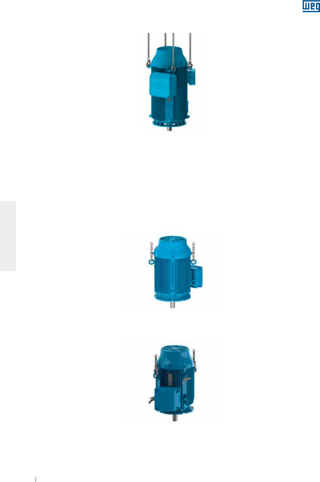
www.weg.net
Motores Eléctricos126
ESPAÑOL
4. Fije la grúa suelta a los otros dos ojales de la parte trasera del motor y levántela hasta que el motor quede
en la posición vertical, ver Figura 4.15.
Figura 4.15 - Motor HGF en posición vertical
Estos procedimientos sirven para movimientos de motores construidos con montaje en posición vertical. Estos
mismos procedimientos pueden ser utilizados para la colocación del motor de posición horizontal a posición
vertical y viceversa.
4.2. PROCEDIMIENTO PARA VIRADA DE MOTORES W22 VERTICALES
Para realizar la virada de motores W22 originalmente en la posición vertical, siga los pasos mostrados abajo:
1. Asegúrese que los ojales estén fijados adecuadamente, conforme ítem 4.1;
2. Instale el primer par de ojales y suspenda el motor, ver Figura 4.16;
Figura 4.16 - Instalación del primer par de ojales
3. Instalar el segundo par de ojales, ver Figura 4.17;
Figura 4.17 - Instalación del segundo par de ojales
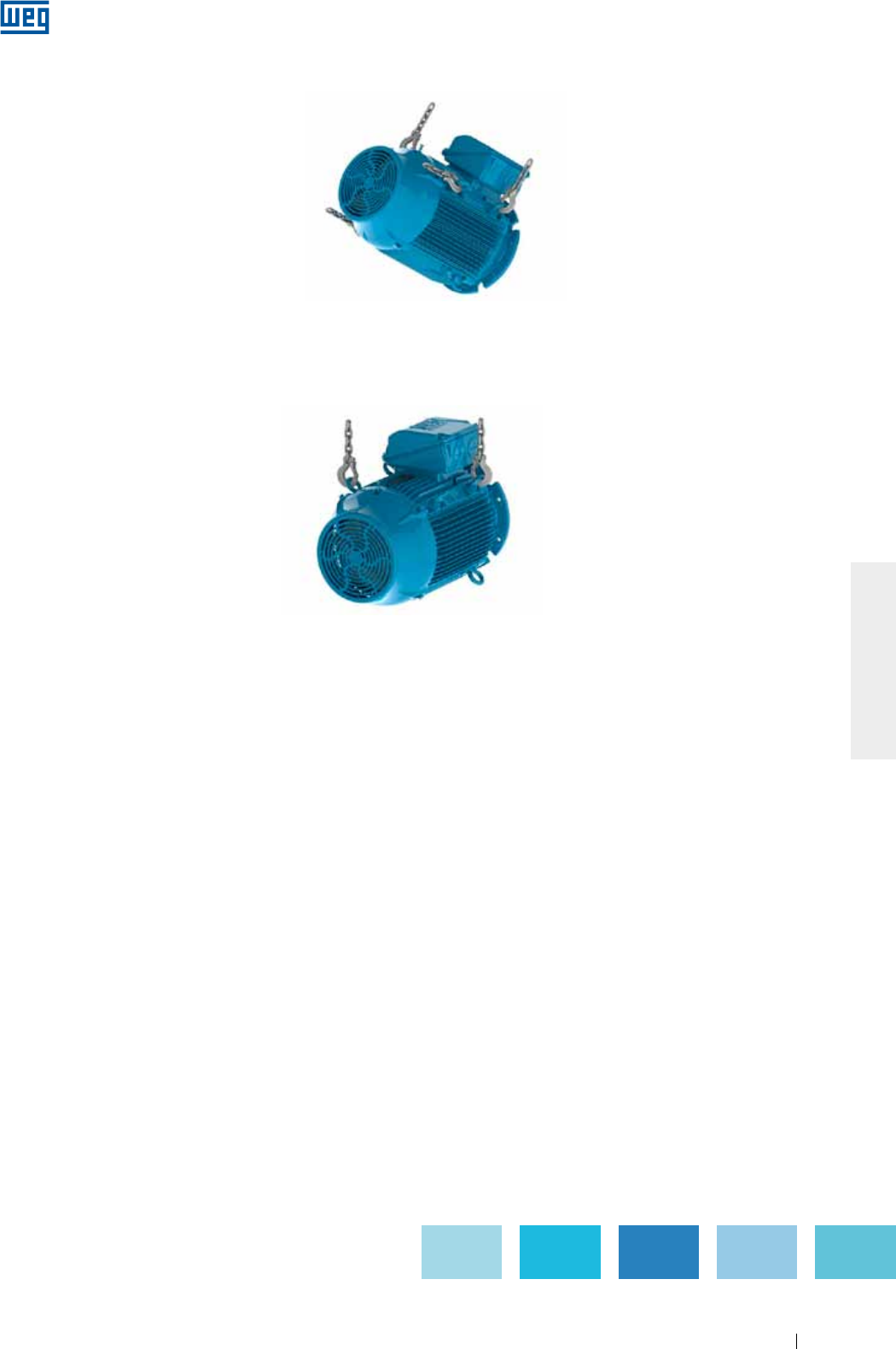
www.weg.net
Motores Eléctricos 127
ESPAÑOL
5. Remueva el primer par de ojales, ver Figura 4.19.
Figura 4.19 - Resultado final: motor posicionado de forma horizontal
4. Reduzca la carga sobre el primer par de ojales para iniciar la rotación del motor, conforme Figura 4.18. Este
procedimiento debe ser realizado de forma lenta y cautelosa;
Figura 4.18 - Motor está siendo rotado para hacia la posición horizontal
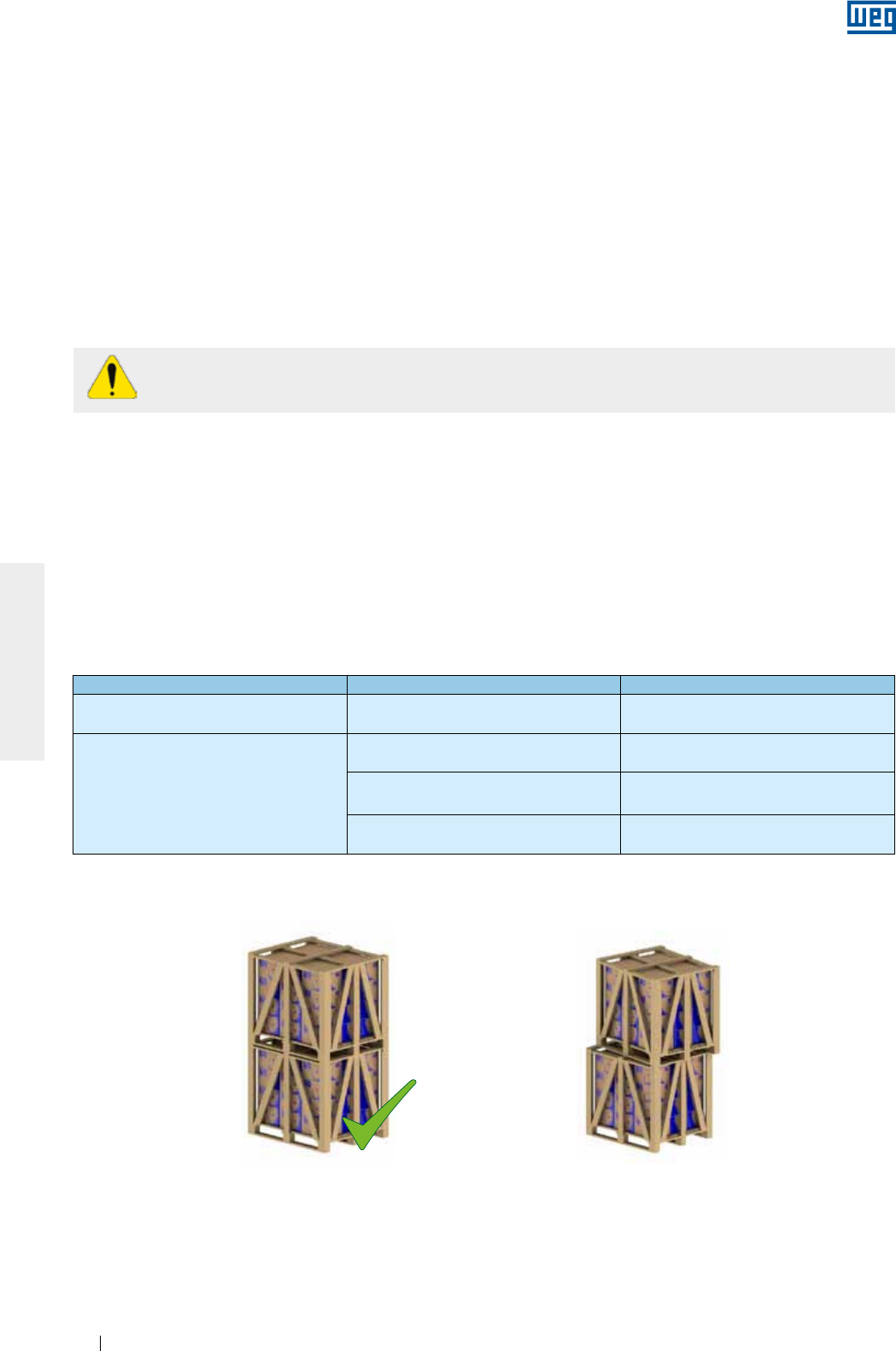
www.weg.net
Motores Eléctricos128
ESPAÑOL
5. ALMACENADO
Si los motores no fueran instalados de inmediato, se recomienda almacenarlos en local seco con humedad
relativa del aire de hasta 60%, con temperatura ambiente por encima de 5 °C y por debajo de 40 °C, libre de
polvo, vibraciones, gases, agentes corrosivos, con temperatura uniforme, en posición normal y sin apoyar otros
objetos sobre los mismos. Remueva las poleas, en caso que existan, de la punta del eje, la que debe ser
mantenida libre y con grasa protectora para evitar corrosión.
En caso que el motor posea resistencia de calentamiento, ésta deberá ser energizada siempre que el motor no
esté en operación. Esto se aplica también a los casos en que el motor está instalado, pero fuera de uso por un
largo período. En estas situaciones, dependiendo de las condiciones del ambiente, podrá ocurrir condensación
de agua en el interior del motor, provocando una caída en la resistencia de aislamiento. Los motores deben ser
almacenados de tal modo que el drenaje de agua condensada sea facilitado (informaciones adicionales están
disponibles en el ítem 6).
Las resistencias de calentamiento nunca deben estar energizadas mientras el motor esté
operando.
5.1. SUPERFICIES MECANIZADAS EXPUESTAS
Todas las superficies mecanizadas expuestas (por ejemplo, punta de eje y brida) son protegidas en la fábrica
por un inhibidor de oxidación temporario. Esta película protectora debe ser reaplicada periódicamente durante
el período de almacenado (por lo menos a cada seis meses) o cuando fuera removida o estuviera deteriorada.
5.2. APILAMIENTO
El apilamiento de embalajes durante el almacenado no debe sobrepasar los 5 metros de altura, obedeciendo
los criterios de la Tabla 5.1:
Tabla 5.1 - Apilamiento máximo recomendado
Tipo de embalaje Carcasas Cantidad máxima de apilamiento
Caja de cartón IEC 63 a 132
NEMA 143 a 215
Indicada en la pestaña superior
de la caja de cartón
Jaula de madera
IEC 63 a 315
NEMA 48 a 504/5 06
IEC 355
NEMA 586/7 y 588/9 03
HGF IEC 315 a 630
HGF NEMA 5000 a 9600 Indicado en el propio embalaje
Notas:
1) No apile embalajes mayores sobre menores;
2) Posicione correctamente un embalaje sobre el otro (ver Figura 5.1 y Figura 5.2);
Figura 5.1 - Montaje adecuado Figura 5.2 - Montaje inadecuado
X
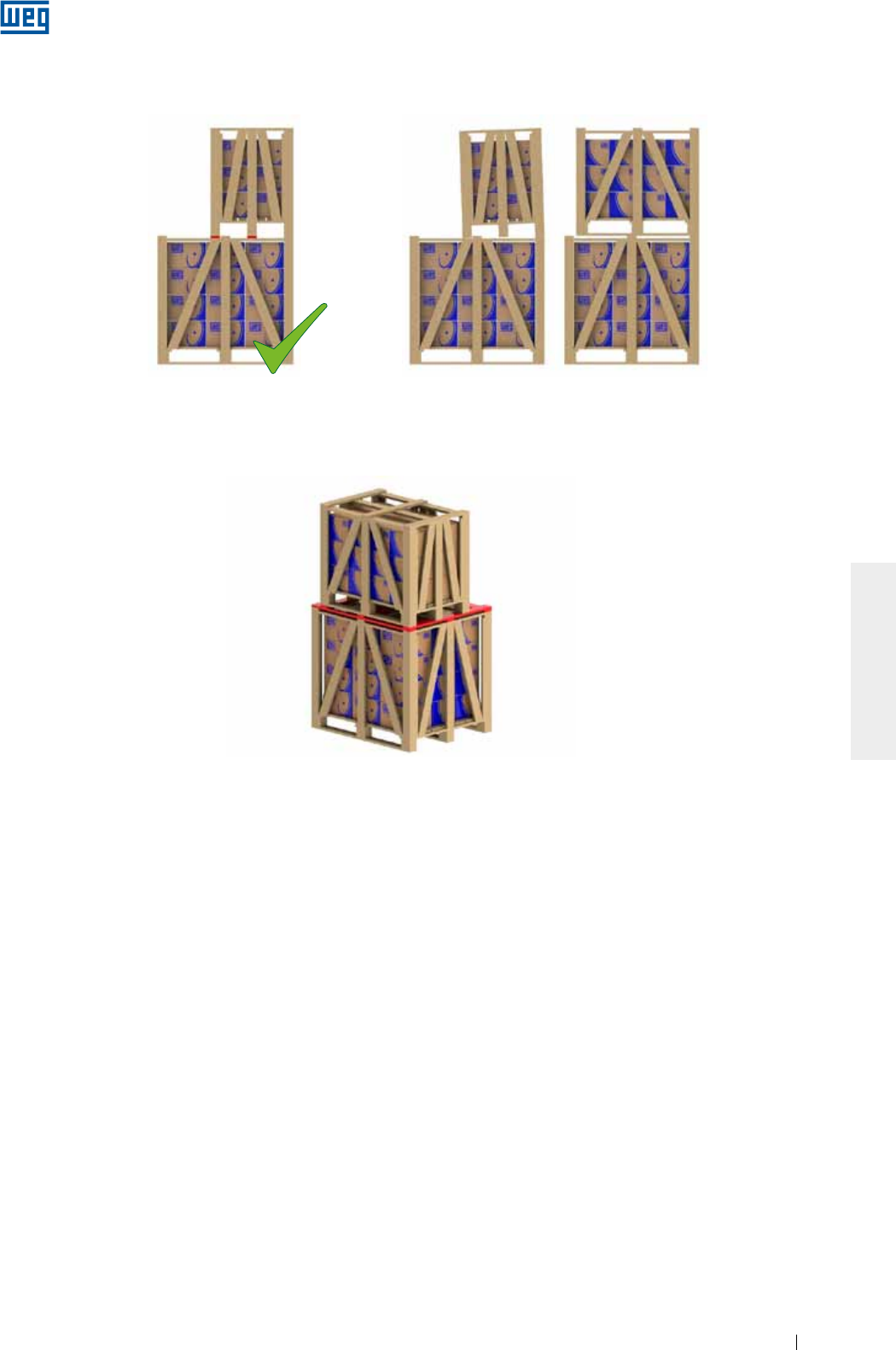
www.weg.net
Motores Eléctricos 129
ESPAÑOL
Figura 5.5 - Utilización de varas adicionales para apilamiento
5.3. COJINETES
5.3.1. Cojinetes de rodamiento lubricados a grasa
Se recomienda girar el eje del motor por lo menos una vez al mes (manualmente, al menos cinco vueltas, dejando el
eje en posición diferente de la original). Obs.: en caso que el motor posea dispositivo de trabado del eje, el mismo
debe ser retirado antes de girar el eje y ser colocado una vez más antes de levantar el motor.
Los motores verticales pueden ser almacenados en posición vertical o en posición horizontal.
Para motores con rodamiento abierto almacenados por más de seis meses, los rodamientos deben ser
relubricados, conforme el ítem 8.2, antes de la entrada en operación.
En caso que el motor permanezca almacenado por un período superior a dos años, se recomienda sustituir los
rodamientos, o de otra forma, deben ser removidos, lavados, inspeccionados y relubricados conforme el ítem 8.2.
5.3.2. Cojinetes de rodamiento con lubricación a aceite
El motor debe ser almacenado en su posición original de funcionamiento, y con aceite en los cojinetes. El nivel
de aceite debe ser respetado, permaneciendo en la mitad del visor de nivel.
Durante el período de almacenado, se debe, retirar el dispositivo de trabado del eje y, mensualmente, rotar el
eje manualmente cinco vueltas, para hacer circular el aceite y conservar el cojinete en buenas condiciones.
Siendo necesario mover el motor, el dispositivo de trabado del eje debe ser reinstalado.
Para motores almacenados por más de seis meses, los rodamientos deben ser relubricados, conforme el ítem
8.2, antes de su puesta en operación.
En caso que el motor permanezca almacenado por un período superior a dos años, se recomienda sustituir los
rodamientos o entonces removerlos, lavarlos, inspeccionarlos y relubricarlos conforme el ítem 8.2.
El aceite de los cojinetes de los motores verticales, que son transportados en posición horizontal, es retirado
para evitar derramamiento durante el transporte. Tras la recepción, estos motores deben ser puestos en
posición vertical y sus cojinetes deben ser lubricados.
Figura 5.3 - Apilamiento adecuado Figura 5.4 - Apilamiento inadecuado
X
4) Para el apilamiento de un volumen menor sobre un volumen mayor, agregue varas transversales entre los mismos cuando el mayor no
ofrezca resistencia al peso del menor (ver Figura 5.5). Esta situación normalmente ocurre con los volúmenes de los motores de carcasa
por encima de la IEC 225S/M (NEMA 364/5T).
3) Las patas de los embalajes superiores deben estar apoyadas sobre calces de madera (Figura 5.3) no sobre cintas de acero ni
pueden permanecer sin apoyo (Figura 5.4);
www.weg.net
Motores Eléctricos130
ESPAÑOL
5.3.3. Cojinetes de rodamiento con lubricación de tipo Oil Mist
Tamaño de rodamiento Cantidad de aceite (ml) Tamaño de rodamiento Cantidad de aceite (ml)
6201 15 6309 65
6202 15 6311 90
6203 15 6312 105
6204 25 6314 150
6205 25 6315 200
6206 35 6316 250
6207 35 6317 300
6208 40 6319 350
6209 40 6320 400
6211 45 6322 550
6212 50 6324 600
6307 45 6326 650
6308 55 6328 700
Durante cualquier manipulación del motor, los cojinetes deben estar sin aceite. De esa forma, antes de la
entrada en operación, todo el aceite de los cojinetes debe ser drenado. Luego de la instalación, en caso que el
sistema de niebla no esté en operación, el aceite debe ser recolocado para garantizar la conservación del
cojinete. En este caso, se debe también proceder con el giro semanal del eje.
5.3.4. Cojinetes de deslizamiento
El motor debe ser almacenado en su posición original de funcionamiento, y con aceite en los cojinetes. El nivel
de aceite debe ser respetado, permaneciendo en la mitad del visor de nivel.
Durante el período de almacenado, se debe, retirar el dispositivo de trabado del eje y, mensualmente, rotar el
eje manualmente 5 vueltas (y a 30 rpm), para hacer circular el aceite y conservar el cojinete en buenas
condiciones. En caso que sea necesario mover el motor, el dispositivo de trabado del eje debe ser reinstalado.
Para motores almacenados por más de seis meses, los cojinetes deben ser relubricados, conforme el ítem 8.2,
antes de su puesta en operación.
En caso que el motor permanezca almacenado por un período mayor que el intervalo de cambio de aceite, o
no sea posible rotar el eje del motor, el aceite debe ser drenado y debe ser aplicada una protección
anticorrosiva y deshumidificadores.
Tabla 5.2 - Cantidad de aceite por rodamiento
5.4. RESISTENCIA DE AISLAMIENTO
Se recomienda medir periódicamente la resistencia de aislamiento de los motores, para de esa forma evaluar
las condiciones de almacenado bajo el punto de vista eléctrico. Si fueran observadas caídas en los valores de
Resistencia de Aislamiento, las condiciones del almacenado deben ser analizadas, evaluadas y corregidas,
cuando sea necesario.
5.4.1. Procedimiento para medición de la resistencia de aislamiento
La medición de la resistencia de aislamiento debe ser realizada en área segura.
Para evitar el riesgo de shock eléctrico, descargue los terminales inmediatamente antes y después
de cada medición. En caso que el motor posea capacitores, éstos deben ser descargados.
La resistencia de aislamiento debe ser medida con un megóhmetro y con el motor parado, frío y
completamente desconectado de la red eléctrica.
El motor debe ser almacenado en posición horizontal. Rellene los cojinetes con aceite mineral ISO VG 68
con la cantidad de aceite indicada en la Tabla 5.2 (también válida para rodamientos con dimensiones
equivalentes). Tras a colocación de aceite en los cojinetes, gire el eje (como mínimo cinco vueltas).
Durante el período de almacenado, se debe retirar el dispositivo de trabado del eje (cuando es suministrado) y
semanalmente rotar el eje manualmente 5 vueltas, dejando el mismo en posición diferente de la original.
Siendo necesario mover el motor, el dispositivo de trabado del eje debe ser reinstalado.
En caso que el motor permanezca almacenado por un período superior a dos años, se recomienda sustituir los
rodamientos o entonces removerlos, lavarlos, inspeccionarlos y relubricarlos conforme el ítem 8.2.
www.weg.net
Motores Eléctricos 131
ESPAÑOL
Tabla 5.3 - Tensión para medición de la resistencia de aislamiento
Tensión nominal del motor (V) Tensión aplicada para la medición de la resistencia de aislamiento (V)
< 1000 500
1000 - 2500 500 - 1000
2501 - 5000 1000 - 2500
5001 - 12000 2500 - 5000
> 12000 5000 - 10000
La medición de la resistencia de aislamiento debe ser corregida para la temperatura de 40 °C conforme Tabla 5.4.
Tabla 5.4 - Factor de Corrección de la Resistencia de Aislamiento para 40 °C
Temperatura de medición
de la resistencia de
aislamiento (°C)
Factor de corrección de la
resistencia de aislamiento
para 40 °C
10 0,125
11 0,134
12 0,144
13 0,154
14 0,165
15 0,177
16 0,189
17 0,203
18 0,218
19 0,233
20 0,250
21 0,268
22 0,287
23 0,308
24 0,330
25 0,354
26 0,379
27 0,406
28 0,435
29 0,467
30 0,500
Temperatura de medición
de la resistencia de
aislamiento (°C)
Factor de corrección de la
resistencia de aislamiento
para 40 °C
30 0,500
31 0,536
32 0,574
33 0,616
34 0,660
35 0,707
36 0,758
37 0,812
38 0,871
39 0,933
40 1,000
41 1,072
42 1,149
43 1,231
44 1,320
45 1,414
46 1,516
47 1,625
48 1,741
49 1,866
50 2,000
La condición del aislamiento del motor deberá ser evaluada comparándose el valor medido con los valores de
la Tabla 5.5 (referenciados a 40 °C):
Es recomendable que cada fase sea aislada y testeada separadamente, permitiendo que sea hecha una
comparación entre la resistencia de aislamiento entre cada fase. Para testear una de las fases, las demás fases
deben estar puestas a tierra.
El test de todas las fases simultáneamente evalúa solamente la resistencia de aislamiento contra tierra. En este
caso no es evaluada la resistencia de aislamiento entre las fases.
Los cables de alimentación, llaves, condensadores, y otros equipamientos externos conectados al motor
pueden influenciar considerablemente la medición de la resistencia de aislamiento. Al realizar estas
mediciones, todos los equipamientos externos deben estar desconectados y puestos a tierra.
La lectura de la resistencia de aislamiento debe ser realizada luego de ser aplicada la tensión ser por el período
de un minuto (1 min). La tensión a ser aplicada debe obedecer la Tabla 5.3.
www.weg.net
Motores Eléctricos132
ESPAÑOL
Los dados indicados en la tabla sirven simplemente como valores de referencia. Se sugiere mantener el
histórico de la resistencia de aislamiento del motor durante toda su vida.
Si la resistencia de aislamiento estuviera baja, el estator del motor puede estar húmedo. En ese caso, se
recomienda llevarlo a un Asistente Técnico Autorizado WEG para que sean realizadas la evaluación y la
reparación adecuadas. Este servicio no está cubierto por el Término de Garantía.
Para procedimiento de adecuación de la resistencia de aislamiento, ver ítem 8.4.
Tabla 5.5 - Avaliação do sistema de isolamento
Valor límite para tensión
nominal hasta 1,1 kV (M)
Valor límite para tensión nominal
por encima de 1,1 kV (M) Situación
Hasta 5 Hasta 100 Peligroso, el motor no debe
operar en esa condición
Entre 5 y 100 Entre 100 y 500 Regular
Entre 100 y 500 Por encima de 500 Bueno
Por encima de 500 Por encima de 1000 Excelente
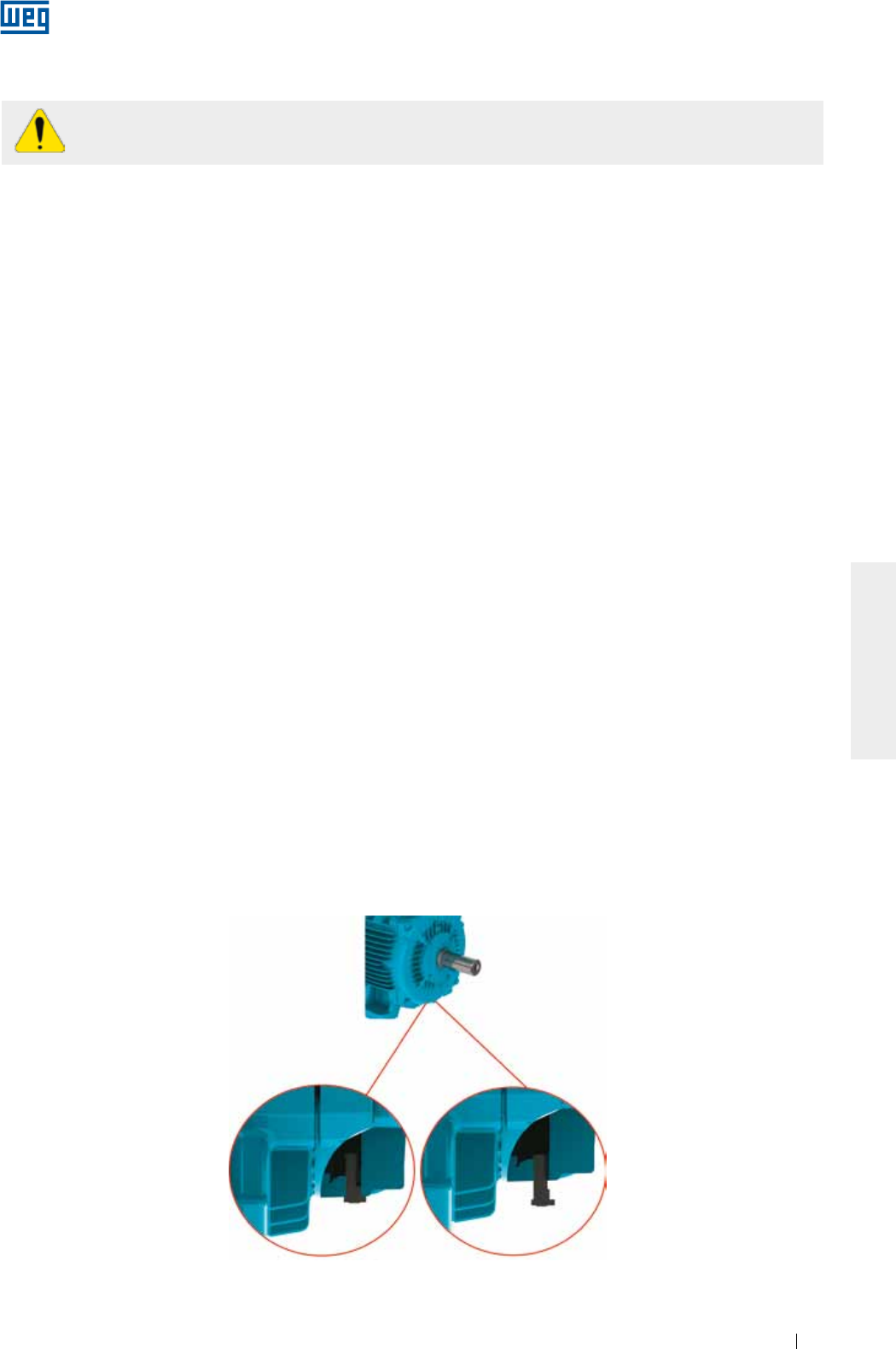
www.weg.net
Motores Eléctricos 133
ESPAÑOL
6. INSTALACION
La instalación de motores debe ser hecha por profesionales capacitados con conocimientos sobre
las normas y las prescripciones de seguridad.
Antes de continuar con el procedimiento de instalación deben ser evaluados algunos puntos:
1. Resistencia de aislamiento: debe estar dentro de los valores aceptables. Ver ítem 5.4.
2. Cojinetes:
a. Rodamientos: si presentan señales de oxidación, deben ser sustituidos. En caso que no presenten
oxidación, realice el procedimiento de relubricación conforme es descrito en el ítem 8.2. Motores
almacenados por un período superior a dos años deben tener sus rodamientos sustituidos antes de ser
puestos en operación;
b. Cojinetes de deslizamiento: para motores almacenados por un período igual o mayor que el intervalo de
cambio de aceite, deben tener su aceite sustituido. En caso que el aceite haya sido retirado, es necesario
retirar el deshumificador y recolocar el aceite en el cojinete. Por mayores informaciones vea el ítem 8.2.
3. Condición de los condensadores de partida: para motores monofásicos almacenados por un período mayor
a dos años, es recomendado que sus condensadores de partida sean sustituidos.
4. Caja de conexión:
a. Deben estar limpias y secas en su interior;
b. Los elementos de contacto deben estar libres de oxidación y correctamente conectados. Ver ítems 6.9 y
6.10;
c. Las entradas de cables no utilizadas deben estar correctamente selladas, la tapa de la caja de conexión
debe ser cerrada y los sellados deben estar en condiciones apropiadas para atender el grado de
protección del motor.
5. Ventilación: las aletas, la entrada y la salida de aire deben estar limpias y desobstruidas. La distancia de
instalación recomendada entre las entradas de aire del motor y la pared no debe ser inferior a ¼ (un cuarto)
del diámetro de la entrada de aire. Se debe asegurar espacio suficiente para la realización de servicios de
limpieza. Ver ítem 7.
6. Acoplamiento: remover el dispositivo de trabado del eje (si existe) y la grasa de protección contra corrosión
de la punta del eje y de la brida solamente puco antes de instalar el motor. Ver ítem 6.4.
7. Drenaje: siempre deben estar posicionados de forma que el drenaje sea facilitado (en el punto más bajo del
motor. En caso que exista una flecha indicadora en el cuerpo del drenaje, el drenaje debe ser montado para
que la misma apunte hacia abajo).
Motores con drenaje de goma salen de la fábrica en la posición y deben ser abiertos periódicamente para
permitir la salida del agua condensado. Para ambientes con elevada condensación del agua y motores con
grado de protección IP55, los drenajes pueden ser armados el la posición abierto (ver Figura 6.1).
Para motores con grado de protección IP56, IP65 o IP66, los drenajes deben permanecer en la posición
cerrado (ver Figura 6.1), siendo abiertos solamente durante el mantenimiento del motor.
Los motores con lubricación de tipo Oil Mist deben tener sus drenajes conectados a un sistema de
recolección específico (ver Figura 6.12).
Figura 6.1 - Detalle del drenaje de goma montado en la posición cerrado y abierto
Drenaje de goma cerrado Drenaje de goma abierto
www.weg.net
Motores Eléctricos134
ESPAÑOL
Remueva o fije completamente la chaveta antes de encender el motor.
Los esfuerzos generados durante la operación, por la carga accionada, deben ser considerados
como parte del dimensionamiento de los cimientos.
El usuario es totalmente responsable por el proyecto, preparación y ejecución de los cimientos.
8. Recomendaciones adicionales
a. Verifique el sentido de rotación del motor, encendiéndolo a vacío antes de acoplarlo a la carga;
b. Para motores montados en posición vertical con la punta de eje hacia abajo, se recomienda el uso de
sombrerete para evitar a penetración de cuerpos extraños en el interior del motor;
c. Para motores montados en la posición vertical con la punta de eje hacia arriba, se recomienda el uso de
un deflector de agua (water slinger ring) para evitar la penetración de agua por el eje.
6.1. CIMIENTOS PARA EL MOTOR
El cimiento es el elemento estructural, base natural o preparada, destinada a soportar los esfuerzos
producidos por los equipamientos instalados, permitiendo la operación de éstos con estabilidad, desempeño y
seguridad.
El proyecto de cimientos debe considerar las estructuras adyacentes para evitar influencia de un equipamiento
sobre el otro, a fin de que no ocurra propagación de vibraciones.
Los cimientos deben ser planos y su elección, detallado y ejecución, exige las características:
a) De la construcción del propio equipamiento, implicando no solamente los valores y forma de actuación de
las cargas, sino que también su finalidad y los límites máximos de las deformaciones y vibraciones
compatibles en cada caso (ejemplo, motores con valores reducidos de: nivel de vibración, planicidad de las
patas, concentricidad de la brida, pulso de la brida, etc.);
b) De las construcciones vecinas, comprendiendo el estado de conservación, estimativa de las cargas
máximas aplicadas, tipo de cimiento y fijación empleadas, así como los niveles de vibración transmitidos por
estas construcciones.
Cuando el motor sea suministrado con tornillo de alineamiento/nivelación, deberá ser prevista en la base una
superficie que permita el alineamiento/nivelación.
Los esfuerzos sobre la fundación pueden ser calculados por las ecuaciones:
F1 = 0,5 * g * m - (4 * Tb / A)
F2 = 0,5 * g * m + (4 * Tb / A)
Donde:
F1 y F2 = esfuerzos en un lado del motor (N);
g = aceleración de la gravedad (9,8 m/s2);
m = peso del motor (kg);
Tb = par máximo del motor (Nm);
A = distancia entre los agujeros de montaje de las patas del motor (vista frontal) (m).

www.weg.net
Motores Eléctricos 135
ESPAÑOL
Los motores pueden ser montados sobre:
g Bases de concreto: más recomendadas y usuales para los motores de gran porte (ver Figura 6.2);
g Bases metálicas: más comunes para motores de pequeño porte (ver Figura 6.3).
Figura 6.3 - Motor instalado sobre base metálica
Figura 6.2 - Motor instalado sobre base de concreto
En las bases metálicas y de concreto puede existir un sistema de deslizamiento. Normalmente son utilizados
en aplicaciones en que el accionamiento ocurre por poleas y correas. Son más flexibles permitiendo montajes
y desmontajes más rápidas, además de permitir ajustes en la tensión de la correa. Otro aspecto importante es
la posición de los tornillos de trabado de la base, que deben ser opuestos y en posición diagonal. El riel más
cercano a la polea motora es colocado de forma que el tornillo de posicionamiento permanezca entre el motor
y la máquina accionada. El otro riel debe ser colocado con el tornillo en posición opuesta (diagonal), como es
presentado en la Figura 6.4.
Para facilitar el montaje, las bases pueden poseer características como:
g Resaltes y/o huecos;
g Tornillos de anclaje con placas sueltas;
g Tornillos fundidos en el concreto;
g Tornillos de nivelación;
g Tornillos de posicionamiento;
g Bloques de hierro o de acero, placas con superficies planas.
Figura 6.4 - Motor instalado sobre base deslizante
También se recomienda que luego de la instalación del motor, las partes metálicas expuestas sean protegidas
contra oxidación.
F1F1
F2F2
A
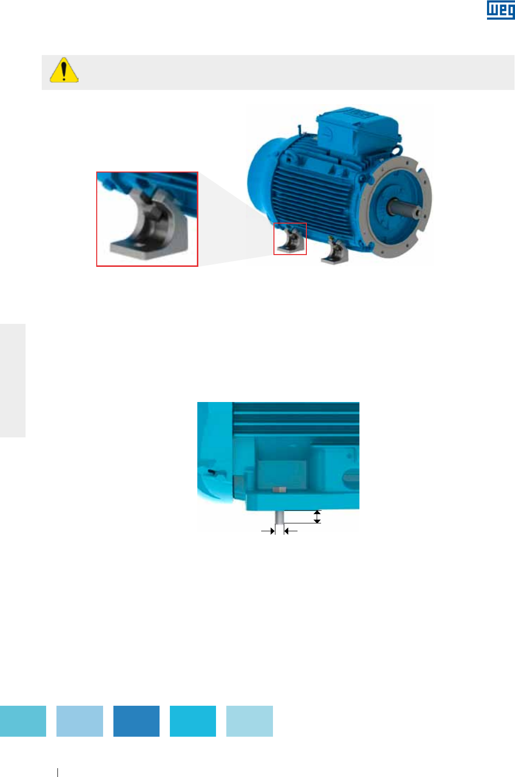
www.weg.net
Motores Eléctricos136
ESPAÑOL
6.2. FIJACION DEL MOTOR
6.2.1. Fijación por las patas
El dimensional de la perforación de las patas, basado en las normas IEC o NEMA, es informado en el catálogo
técnico del producto.
El motor debe ser apoyado sobre la base, alineado y nivelado a fin de que no provoque vibraciones ni
esfuerzos excesivos en el eje o en los cojinetes. Para más detalles, consulte el ítem 6.3 y 6.6.
Se recomienda que el tornillo de fijación tenga longitud roscada libre de 1,5 veces el diámetro del tornillo. En
aplicaciones severas, puede ser necesaria la utilización de una longitud roscada libre mayor. La Figura 6.6
representa la fijación del motor con patas indicando la longitud libre mínima del tornillo.
Figura 6.6 - Representación de la fijación del motor por patas
L = 1.5 x D
D
Motores sin patas suministrados con dispositivos de transporte, de acuerdo con la Figura 6.5,
deben tener sus dispositivos removidos antes de iniciar la instalación del motor.
Figura 6 5 - Dispositivo de transporte para motores sin patas
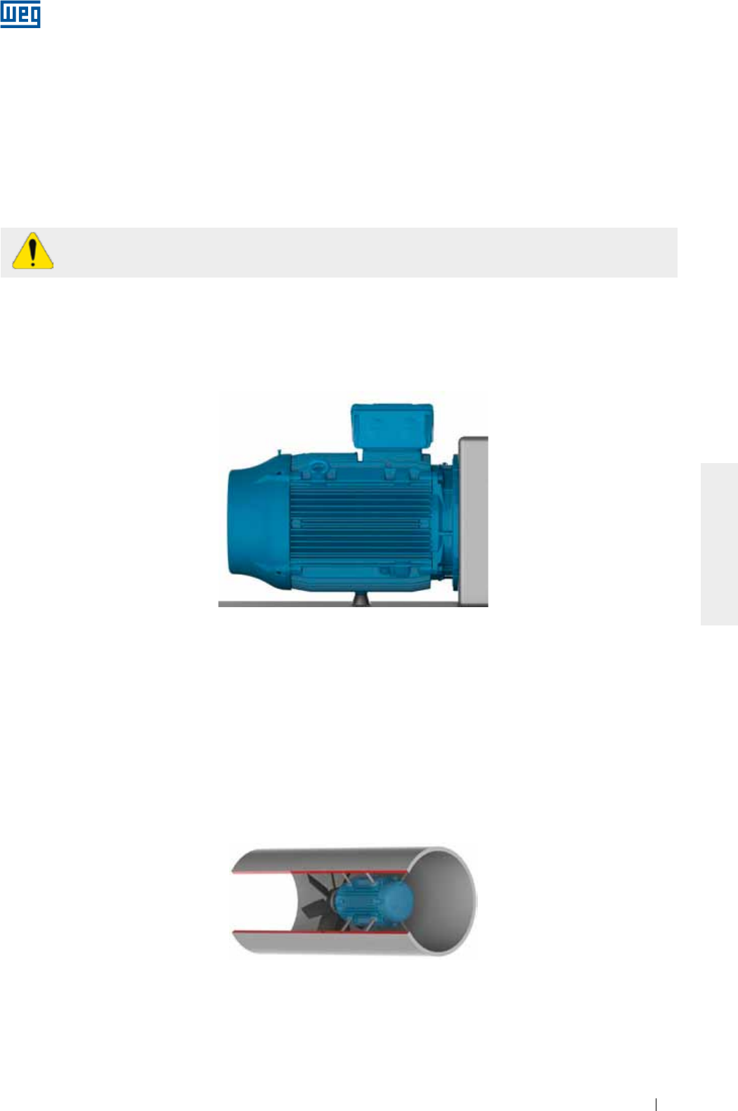
www.weg.net
Motores Eléctricos 137
ESPAÑOL
6.2.2. Fijación por brida
El dimensional de la brida, basado en las normas IEC o NEMA, es informado en el catálogo electrónico o en el
catálogo técnico del producto.
La brida del motor debe ser apoyada en la base, que debe poseer un dimensional de encaje adecuado para el
tamaño de la brida del motor y así asegurar la concentricidad del conjunto.
Dependiendo del tipo de brida, la fijación puede ser realizada desde el motor hacia la base (brida FF(IEC) o D
(NEMA)) o desde la base hacia el motor (brida C (DIN o NEMA)).
Para fijación desde la base hacia el motor, la determinación de la longitud del tornillo debe tomar en
consideración la espesura de la base del usuario y la profundidad de la rosca de la brida del motor.
En los casos que el agujero de la brida es pasante, la longitud del tornillo de fijación del motor no
debe exceder la longitud roscada de la brida para evitar contacto con la bobina del motor.
Para fijación del motor a la base, se recomienda que el tornillo de fijación tenga longitud roscada libre de 1,5
veces el diámetro del tornillo. En aplicaciones severas, puede ser necesaria la utilización de una longitud
roscada libre mayor.
Para fijación de motores de gran porte y/o en aplicaciones severas, se recomienda que, además de la fijación
por brida, el motor sea apoyado (por patas o pad). El motor nunca puede ser apoyado sobre sus aletas. Ver
Figura 6.7.
Figura 6.7 - Representación de la fijación del motor con brida y apoyo en la base de la carcasa
Para aplicación de motores con la presencia de líquidos en el interior de la brida (ej.: aceite), el sellado del
motor debe ser adecuado para impedir la penetración de líquidos en el interior del motor.
6.2.3. Fijación por pad
Este tipo de fijación es normalmente utilizado en ductos de ventilación. La fijación del motor es hecha a través
de perforaciones roscadas en la estructura del motor, cuyo dimensional es informado en el catálogo
electrónico o en el catálogo técnico del producto.
El dimensionamiento de la varilla de fijación/tornillo del motor debe tomar en consideración el dimensional del
ducto de ventilación o base de instalación y la profundidad de la rosca en el motor. Las varillas de fijación y la
pared del ducto deben tener rigidez suficiente para evitar la vibración excesiva del conjunto (motor y ventilador).
La Figura 6.8 representa la fijación por pads.
Figura 6.8 - Representación de la fijación del motor en el interior de un ducto de ventilación
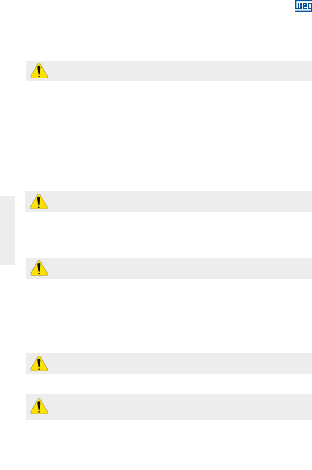
www.weg.net
Motores Eléctricos138
ESPAÑOL
6.3. BALANCEO
Equipamientos desbalanceados generan vibraciones que pueden causar daños al motor. Los motores WEG
son balanceados dinámicamente con “media chaveta” en vacío (desacoplados). Deben ser solicitados
balanceos especiales en el momento de la compra.
Los elementos de transmisión tales como poleas, acoplamientos, etc., deben ser balanceados
antes de ser instalados en los ejes de los motores.
Los motores accionados sin elementos de transmisión acoplados deben tener su chaveta
firmemente fijada o removida, para prevenir accidentes.
En aplicaciones con acoplamiento directo, se recomienda el uso de rodamientos de esferas.
Los motores equipados con cojinetes de deslizamiento deben estar acoplados directamente a la
máquina accionada o por medio de un reductor. Los cojinetes de deslizamiento no permiten el
acoplamiento a través de poleas y correas.
Una tensión excesiva en las correas damnifica los rodamientos y puede provocar la ruptura del eje
del motor.
El grado de calidad de balanceo del motor sigue las normas vigentes para cada línea de producto.
Se recomienda que los desvíos máximos de balanceo sean registrados en el informe de instalación.
6.4. ACOPLAMIENTOS
6.4.1. Acoplamiento directo
Los acoplamientos son utilizados para la transmisión del torque del motor hacia la máquina accionada. Al
utilizar un acoplamiento, deben ser observados los tópicos abajo:
g Utilice herramientas apropiadas para el montaje y desmontaje de los acoplamientos y así evitar daños al
motor;
g Se recomienda la utilización de acoplamientos flexibles, capaces de absorber pequeños desalineamientos
durante la operación del equipamiento;
g Las cargas máximas y límites de velocidad informados en los catálogos de los fabricantes de los
acoplamientos y del motor no deben ser excedidos;
g Realice la nivelación y el alineamiento del motor conforme ítems 6.5 y 6.6, respectivamente.
Cuando el eje del motor está acoplado directamente al eje de la carga accionada, sin el uso de elementos de
transmisión, presenta acoplamiento directo. El acoplamiento directo ofrece menor costo, mayor seguridad
contra accidentes y ocupa menos espacio.
6.4.2. Acoplamiento por engranaje
El acoplamiento por engranajes es utilizado cuando existe la necesidad de una reducción de velocidad.
Es imprescindible que los ejes estén perfectamente alineados, rigurosamente paralelos (en caso de engranajes
rectos) y en el ángulo de engranaje (en caso de engranajes cónicos o helicoidales).
6.4.3. Acoplamiento por poleas y correas
Es un tipo de transmisión utilizado cuando existe la necesidad de una relación de velocidades entre el motor y
la carga accionada.
6.4.4. Acoplamiento de motores equipados con cojinetes de deslizamiento
Los motores equipados con cojinetes de deslizamiento poseen 3 (tres) marcas en la punta del eje, donde la
marca central es la indicación del centro magnético y las otras 2 (dos) marcas externas indican los límites de
movimiento axial permitidos para el rotor, conforme Figura 6.9.
El motor debe ser acoplado de manera que la flecha fijada en la carcasa del cojinete quede posicionada sobre
la marca central, cuando el motor esté en operación. Durante la partida, o incluso en operación, el rotor puede
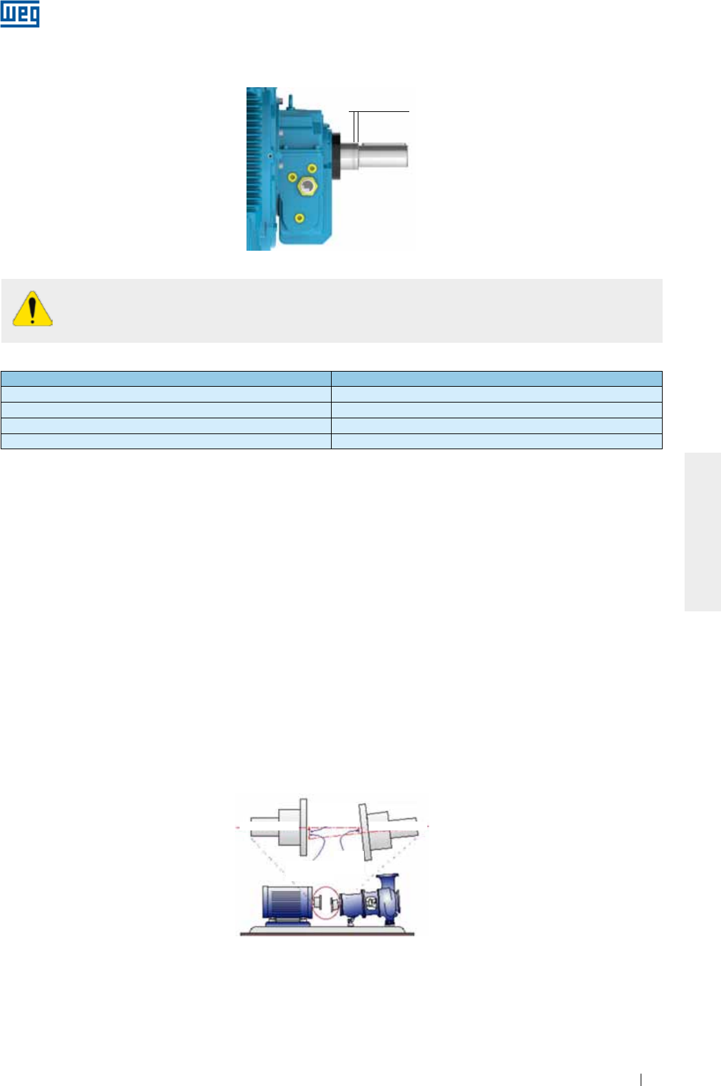
www.weg.net
Motores Eléctricos 139
ESPAÑOL
Holgura axial
Figura 6.9 - Holgura axial en motor equipado con cojinete de deslizamiento
Tabla 6.1 Holguras utilizadas en cojinetes de deslizamiento
Tamaño del cojinete Holgura axial total (mm)
9* 3 + 3 = 6
11* 4 + 4 = 8
14* 5 + 5 =10
18 7,5 + 7,5 = 15
* Para motores conforme la norma API 541, la holgura axial total es 12.7 mm.
Los cojinetes de deslizamiento utilizados por WEG no fueron proyectados para soportar un esfuerzo axial
continuo. La operación continua de la máquina, en sus límites de holgura axial, no es recomendada.
6.5. NIVELACION
La nivelación del motor debe ser realizada para corregir eventuales desvíos de planicidad, que puedan existir
provenientes de otros procesos y acomodaciones de los materiales. La nivelación puede ser realizada por
medio de un tornillo de nivelación fijado a la pata o brida del motor, o por medio de finas chapas de
compensación. Tras la nivelación, la diferencia de altura entre la base de fijación del motor y el motor no debe
exceder 0,1 mm.
En caso que sea utilizada una base metálica para ajustar la altura de la punta de eje del motor con la punta de
eje de la máquina accionada, ésta debe ser nivelada en la base de concreto.
Se recomienda que los desvíos máximos de nivelación sean registrados y almacenados en el informe de
instalación.
6.6. ALINEAMIENTO
El alineamiento entre la máquina motora y la accionada es una de las variables que más contribuyen para
prolongar la vida del motor. El desalineamiento entre los acoplamientos genera elevadas cargas que reducen la
vida útil de los cojinetes, provocan vibraciones y, en casos extremos, pueden causar la ruptura del eje. La
Figura 6.10 ilustra el desalineamiento entre el motor y el equipamiento accionado.
Figura 6.10 - Condición típica de desalineamiento
Al evaluar el acoplamiento, se debe considerar la holgura axial máxima del cojinete conforme la
Tabla 6.1. Las holguras axiales de la máquina accionada y del acoplamiento influencian en la
holgura máxima del cojinete.
El desalineamiento
máximo ocurre
aquí
Offset accinador
mils o mm
Offset
accinado
mils o mm
Eje del accionador Eje del accionado
Para efectuar un buen alineamiento del motor, se deben utilizar herramientas y dispositivos adecuados, tales
como reloj comparador, instrumento de alineamiento a laser, entre otros. El eje debe ser alineado axialmente y
radialmente con el eje de la máquina accionada.
El valor leído en relojes comparadores para el alineamiento, de acuerdo con la Figura 6.11, no debe exceder
0,03 mm, considerando un giro completo del eje. Debe existir una holgura entre los acoplamientos, para
compensar la dilatación térmica de los ejes, conforme especificación del fabricante del acoplamiento.
moverse libremente entre las dos ranuras externas, en caso que la máquina accionada ejerza algún esfuerzo
axial sobre el eje del motor. No obstante, el motor no puede operar de manera constante con esfuerzo axial
sobre el cojinete, bajo ningún concepto.
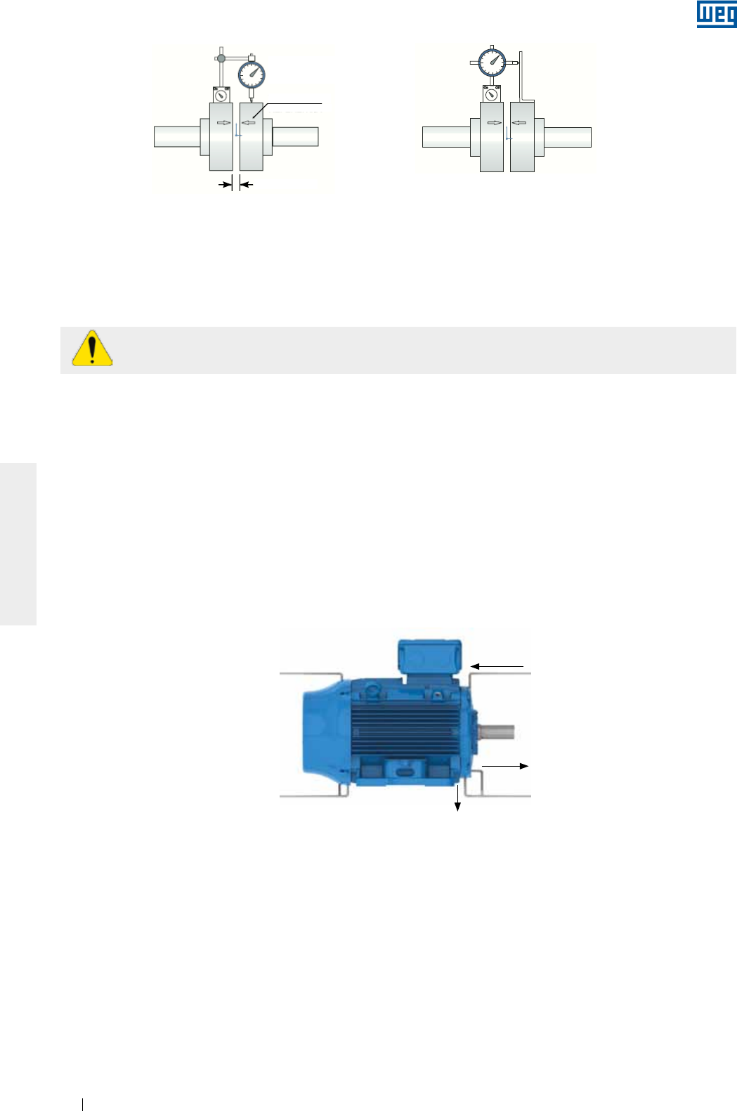
www.weg.net
Motores Eléctricos140
ESPAÑOL
En caso que el alineamiento sea realizado a través de un instrumento a laser, deben ser seguidas las
instrucciones y recomendaciones suministradas por el fabricante del instrumento.
La verificación del alineamiento debe ser realizada a temperatura ambiente y a la temperatura de trabajo de los
equipamientos.
Es recomendado que el alineamiento de los acoplamientos sea verificado periódicamente.
Para acoplamiento por poleas y correas, el alineamiento debe ser realizado de tal modo que el centro de la
polea motora esté en el mismo plano del centro de la polea movida y los ejes del motor y de la máquina estén
perfectamente paralelos.
Luego de la realización de los procedimientos descritos anteriormente, se debe certificar que los dispositivos
de montaje del motor no permitan alteraciones en el alineamiento y en la nivelación y no causen daños al
equipamiento.
Se recomienda que los desvíos máximos de alineamiento sean registrados y almacenados en el informe de
instalación.
6.7. CONEXION DE MOTORES LUBRICADOS A ACEITE O DE TIPO OIL MIST
En motores con lubricación a aceite o de tipo oil mist, se debe conectar los tubos de lubricación existentes
(entrada, salida del cojinete y drenaje del motor), conforme es indicado en la Figura 6.12.
El sistema de lubricación debe garantizar lubricación continua del cojinete, de acuerdo con las especificaciones
del fabricante de este sistema.
Figura 6.12 - Sistema de alimentación y drenaje para motores lubricados por aceite o de tipo Oil Mist
Salida
Entrada
Drenaje
Figura 6.11 - Alineamiento con reloj comparador
Alineamiento paralelo Alineamiento angular
Trazo
GAP
de referencia
Reloj comparador
6.8. CONEXION DEL SISTEMA DE REFRIGERACION A AGUA
En motores con refrigeración a agua, debe ser prevista la instalación de ductos en la entrada y salida de agua
del motor para garantizar su refrigeración. Se debe observar, conforme el ítem 7.2, el flujo mínimo y la
temperatura del agua en la instalación.
6.9. CONEXION ELECTRICA
Para el dimensionamiento de los cables de alimentación y dispositivos de maniobra y protección deben ser
considerados: corriente nominal del motor, factor de servicio, corriente de partida, condiciones del ambiente y
de la instalación, la máxima caída de tensión, etc. conforme las normas vigentes.
Todos los motores deben ser instalados con sistemas de protección contra sobrecarga. Para motores
trifásicos se recomienda la instalación de sistemas de protección contra falta de fase.
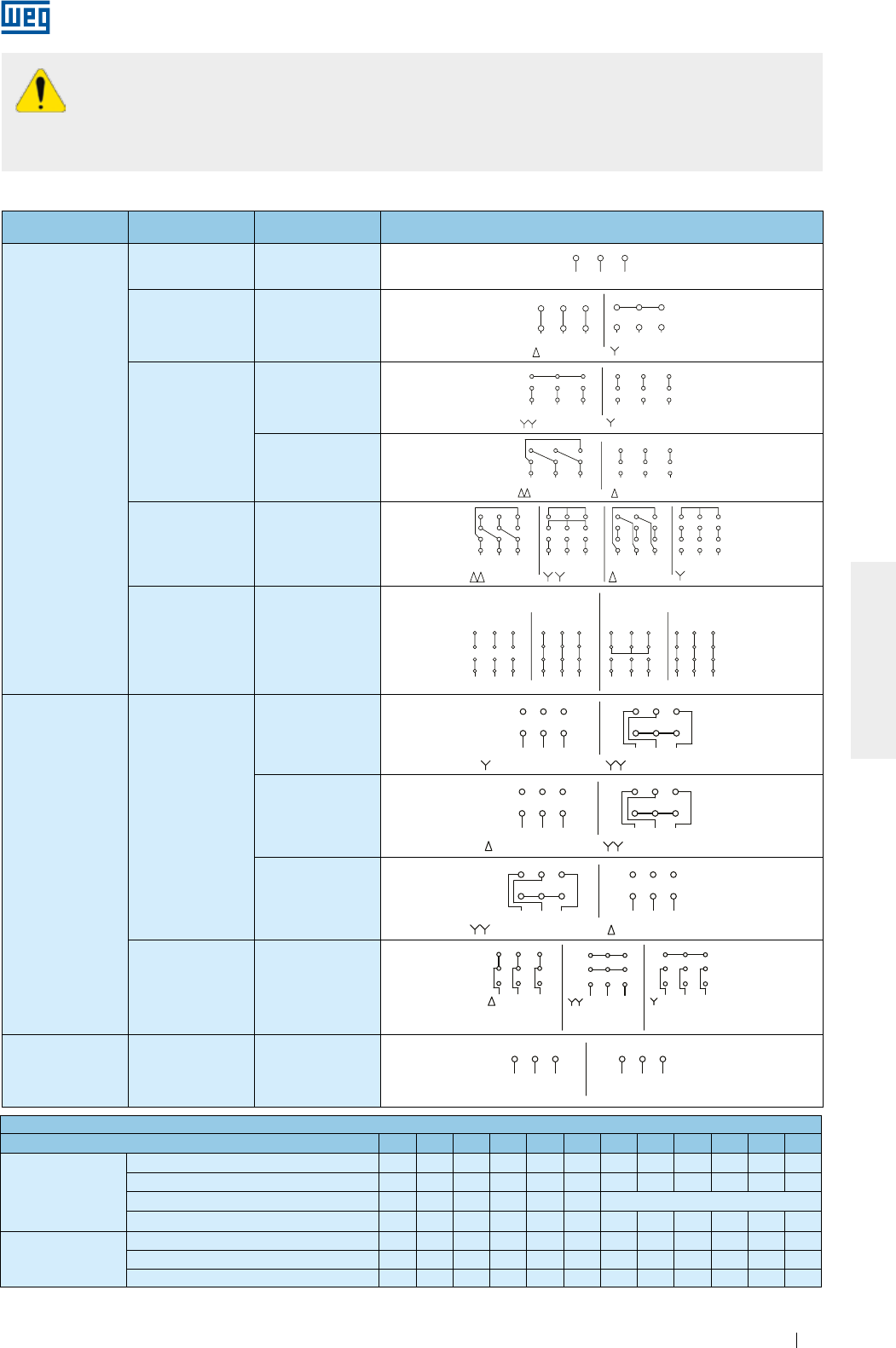
www.weg.net
Motores Eléctricos 141
ESPAÑOL
Antes de conectar el motor, verifique si la tensión y la frecuencia de la red son las mismas
marcadas en la placa de identificación del motor. Siga el diagrama de conexión indicado en la
placa de identificación del motor. Como referencia, pueden ser seguidas los diagramas de
conexión presentados en la Tabla 6.2.
Para evitar accidentes, verifique si la puesta a tierra fue realizada conforme las normas vigentes.
Configuración Cantidad
de cables Tipo de conexión Diagrama de conexión
Velocidad Única
3 -
L1 L2 L3
31 2
L2L1
1
6
L3
2 3
4 5
L2L1
1
6
L3
2 3
4 5
L3L2L1 L3L2L1
5
2
8
7
1
49
3
68
2
5
7
1
49
3
6
45 64
L1
7
1L3
98 32
L2
7
L1
1
65
3
9
L2 L3
2
8
78 9
L3L2
2L1
3
5
11 12
610
1
4
1
32 L3L2 L1
11
5
8
12 10
6
94
71
32 L3L2 L1
11
5
8
12 10
6
94
71
32 L3L2 L1
11
5
8
12 10
6
94
7
L2
4
L1 L2
1 2
6
L3 L1
3
5
L2L3 L1 L3 L1
RUNSTART
12 10
7 8
PART-WINDING
11
9
START
WYE-DELTA
L2 L3
RUN
3
5
9
11
8
4
2
10
1
6
7
12 1012 11
6 4 5
987 321 3
9
5
11
2
8
1
74
10
6
12
1 2
L2L1
6 4
3
L3 L1 L2
5
L3
LOW SPEED HIGH SPEED
LOW SPEED
L1 L3L2 L3
HIGH SPEED
L1 L2
31 2 1 2 3
LOW SPEED L1 L3L2
L3 HIGH SPEED
L1 L2
6
3
4
1
5
2
1 2 3
4 5 6
LOW SPEED
L1 L3L2 L3
HIGH SPEED
L1 L2
6
3
4
1
5
21 2 3
4 5 6
ONLY FOR
STARTING
6
54
L1 L2 L3
87
1 2 9
3
64 5
HIGH SPEED
L1 L2 L3
8
2
7
19
3
LOW SPEED
5
4
L1 L2
8
7
126
L3
9
3
ONLY FOR
STARTING
654
L1 L2 L3
87
1 2 9
3
64 5
HIGH SPEED
L1 L2 L3
8
2
7
19
3
LOW SPEED
5
4
L1 L2
8
7
126
L3
9
3
64 5 4 5 6
L1 L2 L3
31 2
L2L1
1
6
L3
2 3
4 5
L2L1
1
6
L3
2 3
4 5
L3L2L1 L3L2L1
5
2
8
7
1
49
3
68
2
5
7
1
49
3
6
45 64
L1
7
1L3
98 32
L2
7
L1
1
65
3
9
L2 L3
2
8
78 9
L3L2
2L1
3
5
11 12
610
1
4
1
32 L3L2 L1
11
5
8
12 10
6
94
71
32 L3L2 L1
11
5
8
12 10
6
94
71
32 L3L2 L1
11
5
8
12 10
6
94
7
L2
4
L1 L2
1 2
6
L3 L1
3
5
L2L3 L1 L3 L1
12 10
7 8 11
9
L2 L3
3
5
9
11
8
4
2
10
1
6
7
12 1012 11
6 4 5
987 321 3
9
5
11
2
8
1
74
10
6
12
1 2
L2L1
6 4
3
L3 L1 L2
5
L3
L1 L3L2 L3L1 L2
31 2 1 2 3
L1 L3L2
L3L1 L2
6
3
4
1
5
2
1 2 3
4 5 6
L1 L3L2 L3L1 L2
6
3
4
1
5
21 2 3
4 5 6
654
L1 L2 L3
87
1 2 9
3
64 5
L1 L2 L3
8
2
7
19
3
5
4
L1 L2
8
7
126
L3
9
3654
L1 L2 L3
87
1 2 9
3
64 5
L1 L2 L3
8
2
7
19
3
5
4
L1 L2
8
7
126
L3
9
3
64 5 4 5 6
OPERAÇÃOPARTIDA OPERAÇÃOPARTIDA
PART-WINDING ESTRELA-TRIÂNGULO
MENOR ROTAÇÃO
MENOR ROTAÇÃO
MENOR
ROTAÇÃO
MENOR ROTAÇÃO MAIOR ROTAÇÃO
MAIOR ROTAÇÃO
MAIOR ROTAÇÃO
MENOR ROTAÇÃO MAIOR ROTAÇÃO
MAIOR
ROTAÇÃO SOMENTE
PARTIDA
L1 L2 L3
31 2
L2L1
1
6
L3
2 3
4 5
L2L1
1
6
L3
2 3
4 5
L3L2L1 L3L2L1
5
2
8
7
1
49
3
68
2
5
7
1
49
3
6
45 64
L1
7
1L3
98 32
L2
7
L1
1
65
3
9
L2 L3
2
8
78 9
L3L2
2L1
3
5
11 12
610
1
4
1
32 L3L2 L1
11
5
8
12 10
6
94
71
32 L3L2 L1
11
5
8
12 10
6
94
71
32 L3L2 L1
11
5
8
12 10
6
94
7
L2
4
L1 L2
1 2
6
L3 L1
3
5
L2L3 L1 L3 L1
12 10
7 8 11
9
L2 L3
3
5
9
11
8
4
2
10
1
6
7
12 1012 11
6 4 5
987 321 3
9
5
11
2
8
1
74
10
6
12
1 2
L2L1
6 4
3
L3 L1 L2
5
L3
L1 L3L2 L3L1 L2
31 2 1 2 3
L1 L3L2
L3L1 L2
6
3
4
1
5
2
1 2 3
1 2 3
4 5 6
L1 L3L2 L3L1 L2
6
3
4
1
5
21 2 3
4 5 6
654
L1 L2 L3
87
1 2 9
3
64 5
L1 L2 L3
8
2
7
19
3
5
4
L1 L2
8
7
6
L3
9
654
L1 L2 L3
87
1 2 9
3
64 5
L1 L2 L3
8
2
7
19
3
5
4
L1 L2
8
7
6
L3
9
64 5 4 5 6
PART-WINDING
OPERACIÓNARRANQUE OPERACIÓNARRANQUE
ESTRELLA - TRIÁNGULO
MENOR ROTACIÓN MAYOR ROTACIÓN
MENOR ROTACIÓN
MENOR ROTACIÓN
MENOR ROTACIÓN
MAYOR ROTACIÓN
MAYOR ROTACIÓN
MAYOR ROTACIÓN
SÓLO PARA
ARRANQUE
MAYOR
ROTACIÓN
MENOR
ROTACIÓN
6Δ - Y
L1 L2 L3
31 2
L2L1
1
6
L3
2 3
4 5
L2L1
1
6
L3
2 3
4 5
L3L2L1 L3L2L1
5
2
8
7
1
49
3
68
2
5
7
1
49
3
6
45 64
L1
7
1L3
98 32
L2
7
L1
1
65
3
9
L2 L3
2
8
78 9
L3L2
2L1
3
5
11 12
610
1
4
1
32 L3L2 L1
11
5
8
12 10
6
94
71
32 L3L2 L1
11
5
8
12 10
6
94
71
32 L3L2 L1
11
5
8
12 10
6
94
7
L2
4
L1 L2
1 2
6
L3 L1
3
5
L2L3 L1 L3 L1
RUNSTART
12 10
7 8
PART-WINDING
11
9
START
WYE-DELTA
L2 L3
RUN
3
5
9
11
8
4
2
10
1
6
7
12 1012 11
6 4 5
987 321 3
9
5
11
2
8
1
74
10
6
12
1 2
L2L1
6 4
3
L3 L1 L2
5
L3
LOW SPEED HIGH SPEED
LOW SPEED
L1 L3L2 L3
HIGH SPEED
L1 L2
31 2 1 2 3
LOW SPEED L1 L3L2
L3 HIGH SPEED
L1 L2
6
3
4
1
5
2
1 2 3
4 5 6
LOW SPEED
L1 L3L2 L3
HIGH SPEED
L1 L2
6
3
4
1
5
21 2 3
4 5 6
ONLY FOR
STARTING
6
54
L1 L2 L3
87
1 2 9
3
64 5
HIGH SPEED
L1 L2 L3
8
2
7
19
3
LOW SPEED
5
4
L1 L2
8
7
126
L3
9
3
ONLY FOR
STARTING
654
L1 L2 L3
87
1 2 9
3
64 5
HIGH SPEED
L1 L2 L3
8
2
7
19
3
LOW SPEED
5
4
L1 L2
8
7
126
L3
9
3
64 5 4 5 6
L1 L2 L3
31 2
L2L1
1
6
L3
2 3
4 5
L2L1
1
6
L3
2 3
4 5
L3L2L1 L3L2L1
5
2
8
7
1
49
3
68
2
5
7
1
49
3
6
45 64
L1
7
1L3
98 32
L2
7
L1
1
65
3
9
L2 L3
2
8
78 9
L3L2
2L1
3
5
11 12
610
1
4
1
32 L3L2 L1
11
5
8
12 10
6
94
71
32 L3L2 L1
11
5
8
12 10
6
94
71
32 L3L2 L1
11
5
8
12 10
6
94
7
L2
4
L1 L2
1 2
6
L3 L1
3
5
L2L3 L1 L3 L1
12 10
7 8 11
9
L2 L3
3
5
9
11
8
4
2
10
1
6
7
12 1012 11
6 4 5
987 321 3
9
5
11
2
8
1
74
10
6
12
1 2
L2L1
6 4
3
L3 L1 L2
5
L3
L1 L3L2 L3L1 L2
31 2 1 2 3
L1 L3L2
L3L1 L2
6
3
4
1
5
2
1 2 3
4 5 6
L1 L3L2 L3L1 L2
6
3
4
1
5
21 2 3
4 5 6
654
L1 L2 L3
87
1 2 9
3
64 5
L1 L2 L3
8
2
7
19
3
5
4
L1 L2
8
7
126
L3
9
3654
L1 L2 L3
87
1 2 9
3
64 5
L1 L2 L3
8
2
7
19
3
5
4
L1 L2
8
7
126
L3
9
3
64 5 4 5 6
OPERAÇÃOPARTIDA OPERAÇÃOPARTIDA
PART-WINDING ESTRELA-TRIÂNGULO
MENOR ROTAÇÃO
MENOR ROTAÇÃO
MENOR
ROTAÇÃO
MENOR ROTAÇÃO MAIOR ROTAÇÃO
MAIOR ROTAÇÃO
MAIOR ROTAÇÃO
MENOR ROTAÇÃO MAIOR ROTAÇÃO
MAIOR
ROTAÇÃO SOMENTE
PARTIDA
L1 L2 L3
31 2
L2L1
1
6
L3
2 3
4 5
L2L1
1
6
L3
2 3
4 5
L3L2L1 L3L2L1
5
2
8
7
1
49
3
68
2
5
7
1
49
3
6
45 64
L1
7
1L3
98 32
L2
7
L1
1
65
3
9
L2 L3
2
8
78 9
L3L2
2L1
3
5
11 12
610
1
4
1
32 L3L2 L1
11
5
8
12 10
6
94
71
32 L3L2 L1
11
5
8
12 10
6
94
71
32 L3L2 L1
11
5
8
12 10
6
94
7
L2
4
L1 L2
1 2
6
L3 L1
3
5
L2L3 L1 L3 L1
12 10
7 8 11
9
L2 L3
3
5
9
11
8
4
2
10
1
6
7
12 1012 11
6 4 5
987 321 3
9
5
11
2
8
1
74
10
6
12
1 2
L2L1
6 4
3
L3 L1 L2
5
L3
L1 L3L2 L3L1 L2
31 2 1 2 3
L1 L3L2
L3L1 L2
6
3
4
1
5
2
1 2 3
1 2 3
4 5 6
L1 L3L2 L3L1 L2
6
3
4
1
5
21 2 3
4 5 6
654
L1 L2 L3
87
1 2 9
3
64 5
L1 L2 L3
8
2
7
19
3
5
4
L1 L2
8
7
6
L3
9
654
L1 L2 L3
87
1 2 9
3
64 5
L1 L2 L3
8
2
7
19
3
5
4
L1 L2
8
7
6
L3
9
64 5 4 5 6
PART-WINDING
OPERACIÓNARRANQUE OPERACIÓNARRANQUE
ESTRELLA - TRIÁNGULO
MENOR ROTACIÓN MAYOR ROTACIÓN
MENOR ROTACIÓN
MENOR ROTACIÓN
MENOR ROTACIÓN
MAYOR ROTACIÓN
MAYOR ROTACIÓN
MAYOR ROTACIÓN
SÓLO PARA
ARRANQUE
MAYOR
ROTACIÓN
MENOR
ROTACIÓN
9
YY - Y
L1 L2 L3
31 2
L2L1
1
6
L3
2 3
4 5
L2L1
1
6
L3
2 3
4 5
L3L2L1 L3L2L1
5
2
8
7
1
4
9
3
6
8
2
5
7
1
4
9
3
6
45 64
L1
7
1L3
98 32
L2
7
L1
1
65
3
9
L2 L3
2
8
78 9
L3L2
2L1
3
5
11 12
610
1
4
1
32 L3L2 L1
11
5
8
12 10
6
94
71
32 L3L2 L1
11
5
8
12 10
6
94
71
32 L3L2 L1
11
5
8
12 10
6
94
7
L2
4
L1 L2
1 2
6
L3 L1
3
5
L2L3 L1 L3 L1
RUNSTART
12 10
7 8
PART-WINDING
11
9
START
WYE-DELTA
L2 L3
RUN
3
5
9
11
8
4
2
10
1
6
7
12 1012 11
6 4 5
987 321 3
9
5
11
2
8
1
74
10
6
12
1 2
L2L1
6 4
3
L3 L1 L2
5
L3
LOW SPEED HIGH SPEED
LOW SPEED
L1 L3L2 L3
HIGH SPEED
L1 L2
31 2 1 2 3
LOW SPEED L1 L3L2
L3 HIGH SPEED
L1 L2
6
3
4
1
5
2
1 2 3
4 5 6
LOW SPEED
L1 L3L2 L3
HIGH SPEED
L1 L2
6
3
4
1
5
21 2 3
4 5 6
ONLY FOR
STARTING
6
54
L1 L2 L3
87
1 2 9
3
64 5
HIGH SPEED
L1 L2 L3
8
2
7
19
3
LOW SPEED
5
4
L1 L2
8
7
126
L3
9
3
ONLY FOR
STARTING
654
L1 L2 L3
87
1 2 9
3
64 5
HIGH SPEED
L1 L2 L3
8
2
7
19
3
LOW SPEED
5
4
L1 L2
8
7
126
L3
9
3
64 5 4 5 6
L1 L2 L3
31 2
L2L1
1
6
L3
2 3
4 5
L2L1
1
6
L3
2 3
4 5
L3L2L1 L3L2L1
5
2
8
7
1
49
3
68
2
5
7
1
49
3
6
45 64
L1
7
1L3
98 32
L2
7
L1
1
65
3
9
L2 L3
2
8
78 9
L3L2
2L1
3
5
11 12
610
1
4
1
32 L3L2 L1
11
5
8
12 10
6
94
71
32 L3L2 L1
11
5
8
12 10
6
94
71
32 L3L2 L1
11
5
8
12 10
6
94
7
L2
4
L1 L2
1 2
6
L3 L1
3
5
L2L3 L1 L3 L1
12 10
7 8 11
9
L2 L3
3
5
9
11
8
4
2
10
1
6
7
12 1012 11
6 4 5
987 321 3
9
5
11
2
8
1
74
10
6
12
1 2
L2L1
6 4
3
L3 L1 L2
5
L3
L1 L3L2 L3L1 L2
31 2 1 2 3
L1 L3L2
L3L1 L2
6
3
4
1
5
2
1 2 3
4 5 6
L1 L3L2 L3L1 L2
6
3
4
1
5
21 2 3
4 5 6
654
L1 L2 L3
87
1 2 9
3
64 5
L1 L2 L3
8
2
7
19
3
5
4
L1 L2
8
7
126
L3
9
3654
L1 L2 L3
87
1 2 9
3
64 5
L1 L2 L3
8
2
7
19
3
5
4
L1 L2
8
7
126
L3
9
3
64 5 4 5 6
OPERAÇÃOPARTIDA OPERAÇÃOPARTIDA
PART-WINDING ESTRELA-TRIÂNGULO
MENOR ROTAÇÃO
MENOR ROTAÇÃO
MENOR
ROTAÇÃO
MENOR ROTAÇÃO MAIOR ROTAÇÃO
MAIOR ROTAÇÃO
MAIOR ROTAÇÃO
MENOR ROTAÇÃO MAIOR ROTAÇÃO
MAIOR
ROTAÇÃO SOMENTE
PARTIDA
L1 L2 L3
31 2
L2L1
1
6
L3
2 3
4 5
L2L1
1
6
L3
2 3
4 5
L3L2L1 L3L2L1
5
2
8
7
1
49
3
68
2
5
7
1
49
3
6
45 64
L1
7
1L3
98 32
L2
7
L1
1
65
3
9
L2 L3
2
8
78 9
L3L2
2L1
3
5
11 12
610
1
4
1
32 L3L2 L1
11
5
8
12 10
6
94
71
32 L3L2 L1
11
5
8
12 10
6
94
71
32 L3L2 L1
11
5
8
12 10
6
94
7
L2
4
L1 L2
1 2
6
L3 L1
3
5
L2L3 L1 L3 L1
12 10
7 8 11
9
L2 L3
3
5
9
11
8
4
2
10
1
6
7
12 1012 11
6 4 5
987 321 3
9
5
11
2
8
1
74
10
6
12
1 2
L2L1
6 4
3
L3 L1 L2
5
L3
L1 L3L2 L3L1 L2
31 2 1 2 3
L1 L3L2
L3L1 L2
6
3
4
1
5
2
1 2 3
1 2 3
4 5 6
L1 L3L2 L3L1 L2
6
3
4
1
5
21 2 3
4 5 6
654
L1 L2 L3
87
1 2 9
3
64 5
L1 L2 L3
8
2
7
19
3
5
4
L1 L2
8
7
6
L3
9
654
L1 L2 L3
87
1 2 9
3
64 5
L1 L2 L3
8
2
7
19
3
5
4
L1 L2
8
7
6
L3
9
64 5 4 5 6
PART-WINDING
OPERACIÓNARRANQUE OPERACIÓNARRANQUE
ESTRELLA - TRIÁNGULO
MENOR ROTACIÓN MAYOR ROTACIÓN
MENOR ROTACIÓN
MENOR ROTACIÓN
MENOR ROTACIÓN
MAYOR ROTACIÓN
MAYOR ROTACIÓN
MAYOR ROTACIÓN
SÓLO PARA
ARRANQUE
MAYOR
ROTACIÓN
MENOR
ROTACIÓN
ΔΔ - Δ
L1 L2 L3
31 2
L2L1
1
6
L3
2 3
4 5
L2L1
1
6
L3
2 3
4 5
L3L2L1 L3L2L1
5
2
8
7
1
49
3
68
2
5
7
1
49
3
6
45 64
L1
7
1L3
98 32
L2
7
L1
1
65
3
9
L2 L3
2
8
78 9
L3L2
2L1
3
5
11 12
610
1
4
1
32 L3L2 L1
11
5
8
12 10
6
94
71
32 L3L2 L1
11
5
8
12 10
6
94
71
32 L3L2 L1
11
5
8
12 10
6
94
7
L2
4
L1 L2
1 2
6
L3 L1
3
5
L2L3 L1 L3 L1
RUNSTART
12 10
7 8
PART-WINDING
11
9
START
WYE-DELTA
L2 L3
RUN
3
5
9
11
8
4
2
10
1
6
7
12 1012 11
6 4 5
987 321 3
9
5
11
2
8
1
74
10
6
12
1 2
L2L1
6 4
3
L3 L1 L2
5
L3
LOW SPEED HIGH SPEED
LOW SPEED
L1 L3L2 L3
HIGH SPEED
L1 L2
31 2 1 2 3
LOW SPEED L1 L3L2
L3 HIGH SPEED
L1 L2
6
3
4
1
5
2
1 2 3
4 5 6
LOW SPEED
L1 L3L2 L3
HIGH SPEED
L1 L2
6
3
4
1
5
21 2 3
4 5 6
ONLY FOR
STARTING
6
54
L1 L2 L3
87
1 2 9
3
64 5
HIGH SPEED
L1 L2 L3
8
2
7
19
3
LOW SPEED
5
4
L1 L2
8
7
126
L3
9
3
ONLY FOR
STARTING
654
L1 L2 L3
87
1 2 9
3
64 5
HIGH SPEED
L1 L2 L3
8
2
7
19
3
LOW SPEED
5
4
L1 L2
8
7
126
L3
9
3
64 5 4 5 6
L1 L2 L3
31 2
L2L1
1
6
L3
2 3
4 5
L2L1
1
6
L3
2 3
4 5
L3L2L1 L3L2L1
5
2
8
7
1
49
3
68
2
5
7
1
49
3
6
45 64
L1
7
1L3
98 32
L2
7
L1
1
65
3
9
L2 L3
2
8
78 9
L3L2
2L1
3
5
11 12
610
1
4
1
32 L3L2 L1
11
5
8
12 10
6
94
71
32 L3L2 L1
11
5
8
12 10
6
94
71
32 L3L2 L1
11
5
8
12 10
6
94
7
L2
4
L1 L2
1 2
6
L3 L1
3
5
L2L3 L1 L3 L1
12 10
7 8 11
9
L2 L3
3
5
9
11
8
4
2
10
1
6
7
12 1012 11
6 4 5
987 321 3
9
5
11
2
8
1
74
10
6
12
1 2
L2L1
6 4
3
L3 L1 L2
5
L3
L1 L3L2 L3L1 L2
31 2 1 2 3
L1 L3L2
L3L1 L2
6
3
4
1
5
2
1 2 3
4 5 6
L1 L3L2 L3L1 L2
6
3
4
1
5
21 2 3
4 5 6
654
L1 L2 L3
87
1 2 9
3
64 5
L1 L2 L3
8
2
7
19
3
5
4
L1 L2
8
7
126
L3
9
3654
L1 L2 L3
87
1 2 9
3
64 5
L1 L2 L3
8
2
7
19
3
5
4
L1 L2
8
7
126
L3
9
3
64 5 4 5 6
OPERAÇÃOPARTIDA OPERAÇÃOPARTIDA
PART-WINDING ESTRELA-TRIÂNGULO
MENOR ROTAÇÃO
MENOR ROTAÇÃO
MENOR
ROTAÇÃO
MENOR ROTAÇÃO MAIOR ROTAÇÃO
MAIOR ROTAÇÃO
MAIOR ROTAÇÃO
MENOR ROTAÇÃO MAIOR ROTAÇÃO
MAIOR
ROTAÇÃO SOMENTE
PARTIDA
L1 L2 L3
31 2
L2L1
1
6
L3
2 3
4 5
L2L1
1
6
L3
2 3
4 5
L3L2L1 L3L2L1
5
2
8
7
1
49
3
68
2
5
7
1
49
3
6
45 64
L1
7
1L3
98 32
L2
7
L1
1
65
3
9
L2 L3
2
8
78 9
L3L2
2L1
3
5
11 12
610
1
4
1
32 L3L2 L1
11
5
8
12 10
6
94
71
32 L3L2 L1
11
5
8
12 10
6
94
71
32 L3L2 L1
11
5
8
12 10
6
94
7
L2
4
L1 L2
1 2
6
L3 L1
3
5
L2L3 L1 L3 L1
12 10
7 8 11
9
L2 L3
3
5
9
11
8
4
2
10
1
6
7
12 1012 11
6 4 5
987 321 3
9
5
11
2
8
1
74
10
6
12
1 2
L2L1
6 4
3
L3 L1 L2
5
L3
L1 L3L2 L3L1 L2
31 2 1 2 3
L1 L3L2
L3L1 L2
6
3
4
1
5
2
1 2 3
1 2 3
4 5 6
L1 L3L2 L3L1 L2
6
3
4
1
5
21 2 3
4 5 6
654
L1 L2 L3
87
1 2 9
3
64 5
L1 L2 L3
8
2
7
19
3
5
4
L1 L2
8
7
6
L3
9
654
L1 L2 L3
87
1 2 9
3
64 5
L1 L2 L3
8
2
7
19
3
5
4
L1 L2
8
7
6
L3
9
64 5 4 5 6
PART-WINDING
OPERACIÓNARRANQUE OPERACIÓNARRANQUE
ESTRELLA - TRIÁNGULO
MENOR ROTACIÓN MAYOR ROTACIÓN
MENOR ROTACIÓN
MENOR ROTACIÓN
MENOR ROTACIÓN
MAYOR ROTACIÓN
MAYOR ROTACIÓN
MAYOR ROTACIÓN
SÓLO PARA
ARRANQUE
MAYOR
ROTACIÓN
MENOR
ROTACIÓN
ΔΔ - YY - Δ - Y
L1 L2 L3
31 2
L2L1
1
6
L3
2 3
4 5
L2L1
1
6
L3
2 3
4 5
L3L2L1 L3L2L1
5
2
8
7
1
49
3
68
2
5
7
1
49
3
6
45 64
L1
7
1L3
98 32
L2
7
L1
1
65
3
9
L2 L3
2
8
78 9
L3L2
2L1
3
5
11 12
610
1
4
1
32 L3L2 L1
11
5
8
12 10
6
94
71
32 L3L2 L1
11
5
8
12 10
6
94
71
32 L3L2 L1
11
5
8
12 10
6
94
7
L2
4
L1 L2
1 2
6
L3 L1
3
5
L2L3 L1 L3 L1
RUNSTART
12 10
7 8
PART-WINDING
11
9
START
WYE-DELTA
L2 L3
RUN
3
5
9
11
8
4
2
10
1
6
7
12 1012 11
6 4 5
987 321 3
9
5
11
2
8
1
74
10
6
12
1 2
L2L1
6 4
3
L3 L1 L2
5
L3
LOW SPEED HIGH SPEED
LOW SPEED
L1 L3L2 L3
HIGH SPEED
L1 L2
31 2 1 2 3
LOW SPEED L1 L3L2
L3 HIGH SPEED
L1 L2
6
3
4
1
5
2
1 2 3
4 5 6
LOW SPEED
L1 L3L2 L3
HIGH SPEED
L1 L2
6
3
4
1
5
21 2 3
4 5 6
ONLY FOR
STARTING
6
54
L1 L2 L3
87
1 2 9
3
64 5
HIGH SPEED
L1 L2 L3
8
2
7
19
3
LOW SPEED
5
4
L1 L2
8
7
126
L3
9
3
ONLY FOR
STARTING
654
L1 L2 L3
87
1 2 9
3
64 5
HIGH SPEED
L1 L2 L3
8
2
7
19
3
LOW SPEED
5
4
L1 L2
8
7
126
L3
9
3
64 5 4 5 6
L1 L2 L3
31 2
L2L1
1
6
L3
2 3
4 5
L2L1
1
6
L3
2 3
4 5
L3L2L1 L3L2L1
5
2
8
7
1
49
3
68
2
5
7
1
49
3
6
45 64
L1
7
1L3
98 32
L2
7
L1
1
65
3
9
L2 L3
2
8
78 9
L3L2
2L1
3
5
11 12
610
1
4
1
32 L3L2 L1
11
5
8
12 10
6
94
71
32 L3L2 L1
11
5
8
12 10
6
94
71
32 L3L2 L1
11
5
8
12 10
6
94
7
L2
4
L1 L2
1 2
6
L3 L1
3
5
L2L3 L1 L3 L1
12 10
7 8 11
9
L2 L3
3
5
9
11
8
4
2
10
1
6
7
12 1012 11
6 4 5
987 321 3
9
5
11
2
8
1
74
10
6
12
1 2
L2L1
6 4
3
L3 L1 L2
5
L3
L1 L3L2 L3L1 L2
31 2 1 2 3
L1 L3L2
L3L1 L2
6
3
4
1
5
2
1 2 3
4 5 6
L1 L3L2 L3L1 L2
6
3
4
1
5
21 2 3
4 5 6
654
L1 L2 L3
87
1 2 9
3
64 5
L1 L2 L3
8
2
7
19
3
5
4
L1 L2
8
7
126
L3
9
3654
L1 L2 L3
87
1 2 9
3
64 5
L1 L2 L3
8
2
7
19
3
5
4
L1 L2
8
7
126
L3
9
3
64 5 4 5 6
OPERAÇÃOPARTIDA OPERAÇÃOPARTIDA
PART-WINDING ESTRELA-TRIÂNGULO
MENOR ROTAÇÃO
MENOR ROTAÇÃO
MENOR
ROTAÇÃO
MENOR ROTAÇÃO MAIOR ROTAÇÃO
MAIOR ROTAÇÃO
MAIOR ROTAÇÃO
MENOR ROTAÇÃO MAIOR ROTAÇÃO
MAIOR
ROTAÇÃO SOMENTE
PARTIDA
L1 L2 L3
31 2
L2L1
1
6
L3
2 3
4 5
L2L1
1
6
L3
2 3
4 5
L3L2L1 L3L2L1
5
2
8
7
1
49
3
68
2
5
7
1
49
3
6
45 64
L1
7
1L3
98 32
L2
7
L1
1
65
3
9
L2 L3
2
8
78 9
L3L2
2L1
3
5
11 12
610
1
4
1
32 L3L2 L1
11
5
8
12 10
6
94
71
32 L3L2 L1
11
5
8
12 10
6
94
71
32 L3L2 L1
11
5
8
12 10
6
94
7
L2
4
L1 L2
1 2
6
L3 L1
3
5
L2L3 L1 L3 L1
12 10
7 8 11
9
L2 L3
3
5
9
11
8
4
2
10
1
6
7
12 1012 11
6 4 5
987 321 3
9
5
11
2
8
1
74
10
6
12
1 2
L2L1
6 4
3
L3 L1 L2
5
L3
L1 L3L2 L3L1 L2
31 2 1 2 3
L1 L3L2
L3L1 L2
6
3
4
1
5
2
1 2 3
1 2 3
4 5 6
L1 L3L2 L3L1 L2
6
3
4
1
5
21 2 3
4 5 6
654
L1 L2 L3
87
1 2 9
3
64 5
L1 L2 L3
8
2
7
19
3
5
4
L1 L2
8
7
6
L3
9
654
L1 L2 L3
87
1 2 9
3
64 5
L1 L2 L3
8
2
7
19
3
5
4
L1 L2
8
7
6
L3
9
64 5 4 5 6
PART-WINDING
OPERACIÓNARRANQUE OPERACIÓNARRANQUE
ESTRELLA - TRIÁNGULO
MENOR ROTACIÓN MAYOR ROTACIÓN
MENOR ROTACIÓN
MENOR ROTACIÓN
MENOR ROTACIÓN
MAYOR ROTACIÓN
MAYOR ROTACIÓN
MAYOR ROTACIÓN
SÓLO PARA
ARRANQUE
MAYOR
ROTACIÓN
MENOR
ROTACIÓN
12
Δ - PWS
Arranque
Part-winding
L1 L2 L3
31 2
L2L1
1
6
L3
2 3
4 5
L2L1
1
6
L3
2 3
4 5
L3L2L1 L3L2L1
5
2
8
7
1
49
3
68
2
5
7
1
49
3
6
45 64
L1
7
1L3
98 32
L2
7
L1
1
65
3
9
L2 L3
2
8
78 9
L3L2
2L1
3
5
11 12
610
1
4
1
32 L3L2 L1
11
5
8
12 10
6
94
71
32 L3L2 L1
11
5
8
12 10
6
94
71
32 L3L2 L1
11
5
8
12 10
6
94
7
L2
4
L1 L2
1 2
6
L3 L1
3
5
L2L3 L1 L3 L1
RUNSTART
12 10
7 8
PART-WINDING
11
9
START
WYE-DELTA
L2 L3
RUN
3
5
9
11
8
4
2
10
1
6
7
12 1012 11
6 4 5
987 321 3
9
5
11
2
8
1
74
10
6
12
1 2
L2L1
6 4
3
L3 L1 L2
5
L3
LOW SPEED HIGH SPEED
LOW SPEED
L1 L3L2 L3
HIGH SPEED
L1 L2
31 2 1 2 3
LOW SPEED L1 L3L2
L3 HIGH SPEED
L1 L2
6
3
4
1
5
2
1 2 3
4 5 6
LOW SPEED
L1 L3L2 L3
HIGH SPEED
L1 L2
6
3
4
1
5
21 2 3
4 5 6
ONLY FOR
STARTING
6
54
L1 L2 L3
87
1 2 9
3
64 5
HIGH SPEED
L1 L2 L3
8
2
7
19
3
LOW SPEED
5
4
L1 L2
8
7
126
L3
9
3
ONLY FOR
STARTING
654
L1 L2 L3
87
1 2 9
3
64 5
HIGH SPEED
L1 L2 L3
8
2
7
19
3
LOW SPEED
5
4
L1 L2
8
7
126
L3
9
3
64 5 4 5 6
L1 L2 L3
31 2
L2L1
1
6
L3
2 3
4 5
L2L1
1
6
L3
2 3
4 5
L3L2L1 L3L2L1
5
2
8
7
1
49
3
68
2
5
7
1
49
3
6
45 64
L1
7
1L3
98 32
L2
7
L1
1
65
3
9
L2 L3
2
8
78 9
L3L2
2L1
3
5
11 12
610
1
4
1
32 L3L2 L1
11
5
8
12 10
6
94
71
32 L3L2 L1
11
5
8
12 10
6
94
71
32 L3L2 L1
11
5
8
12 10
6
94
7
L2
4
L1 L2
1 2
6
L3 L1
3
5
L2L3 L1 L3 L1
12 10
7 8 11
9
L2 L3
3
5
9
11
8
4
2
10
1
6
7
12 1012 11
6 4 5
987 321 3
9
5
11
2
8
1
74
10
6
12
1 2
L2L1
6 4
3
L3 L1 L2
5
L3
L1 L3L2 L3L1 L2
31 2 1 2 3
L1 L3L2
L3L1 L2
6
3
4
1
5
2
1 2 3
4 5 6
L1 L3L2 L3L1 L2
6
3
4
1
5
21 2 3
4 5 6
654
L1 L2 L3
87
1 2 9
3
64 5
L1 L2 L3
8
2
7
19
3
5
4
L1 L2
8
7
126
L3
9
3654
L1 L2 L3
87
1 2 9
3
64 5
L1 L2 L3
8
2
7
19
3
5
4
L1 L2
8
7
126
L3
9
3
64 5 4 5 6
OPERAÇÃOPARTIDA OPERAÇÃOPARTIDA
PART-WINDING ESTRELA-TRIÂNGULO
MENOR ROTAÇÃO
MENOR ROTAÇÃO
MENOR
ROTAÇÃO
MENOR ROTAÇÃO MAIOR ROTAÇÃO
MAIOR ROTAÇÃO
MAIOR ROTAÇÃO
MENOR ROTAÇÃO MAIOR ROTAÇÃO
MAIOR
ROTAÇÃO SOMENTE
PARTIDA
L1 L2 L3
31 2
L2L1
1
6
L3
2 3
4 5
L2L1
1
6
L3
2 3
4 5
L3L2L1 L3L2L1
5
2
8
7
1
49
3
68
2
5
7
1
49
3
6
45 64
L1
7
1L3
98 32
L2
7
L1
1
65
3
9
L2 L3
2
8
78 9
L3L2
2L1
3
5
11 12
610
1
4
1
32 L3L2 L1
11
5
8
12 10
6
94
71
32 L3L2 L1
11
5
8
12 10
6
94
71
32 L3L2 L1
11
5
8
12 10
6
94
7
L2
4
L1 L2
1 2
6
L3 L1
3
5
L2L3 L1 L3 L1
12 10
7 8 11
9
L2 L3
3
5
9
11
8
4
2
10
1
6
7
12 1012 11
6 4 5
987 321 3
9
5
11
2
8
1
74
10
6
12
1 2
L2L1
6 4
3
L3 L1 L2
5
L3
L1 L3L2 L3L1 L2
31 2 1 2 3
L1 L3L2
L3L1 L2
6
3
4
1
5
2
1 2 3
1 2 3
4 5 6
L1 L3L2 L3L1 L2
6
3
4
1
5
21 2 3
4 5 6
654
L1 L2 L3
87
1 2 9
3
64 5
L1 L2 L3
8
2
7
19
3
5
4
L1 L2
8
7
6
L3
9
654
L1 L2 L3
87
1 2 9
3
64 5
L1 L2 L3
8
2
7
19
3
5
4
L1 L2
8
7
6
L3
9
64 5 4 5 6
PART-WINDING
OPERACIÓNARRANQUE OPERACIÓNARRANQUE
ESTRELLA - TRIÁNGULO
MENOR ROTACIÓN MAYOR ROTACIÓN
MENOR ROTACIÓN
MENOR ROTACIÓN
MENOR ROTACIÓN
MAYOR ROTACIÓN
MAYOR ROTACIÓN
MAYOR ROTACIÓN
SÓLO PARA
ARRANQUE
MAYOR
ROTACIÓN
MENOR
ROTACIÓN
Dos velocidades
Dahlander
6
YY - Y
Par Variable
L1 L2 L3
31 2
L2L1
1
6
L3
2 3
4 5
L2L1
1
6
L3
2 3
4 5
L3L2L1 L3L2L1
5
2
8
7
1
49
3
68
2
5
7
1
49
3
6
45 64
L1
7
1L3
98 32
L2
7
L1
1
65
3
9
L2 L3
2
8
78 9
L3L2
2L1
3
5
11 12
610
1
4
1
32 L3L2 L1
11
5
8
12 10
6
94
71
32 L3L2 L1
11
5
8
12 10
6
94
71
32 L3L2 L1
11
5
8
12 10
6
94
7
L2
4
L1 L2
1 2
6
L3 L1
3
5
L2L3 L1 L3 L1
RUNSTART
12 10
7 8
PART-WINDING
11
9
START
WYE-DELTA
L2 L3
RUN
3
5
9
11
8
4
2
10
1
6
7
12 1012 11
6 4 5
987 321 3
9
5
11
2
8
1
74
10
6
12
1 2
L2L1
6 4
3
L3 L1 L2
5
L3
LOW SPEED HIGH SPEED
LOW SPEED
L1 L3L2 L3
HIGH SPEED
L1 L2
31 2 1 2 3
LOW SPEED L1 L3L2
L3 HIGH SPEED
L1 L2
6
3
4
1
5
2
1 2 3
4 5 6
LOW SPEED
L1 L3L2 L3
HIGH SPEED
L1 L2
6
3
4
1
5
21 2 3
4 5 6
ONLY FOR
STARTING
6
54
L1 L2 L3
87
1 2 9
3
64 5
HIGH SPEED
L1 L2 L3
8
2
7
19
3
LOW SPEED
5
4
L1 L2
8
7
126
L3
9
3
ONLY FOR
STARTING
654
L1 L2 L3
87
1 2 9
3
64 5
HIGH SPEED
L1 L2 L3
8
2
7
19
3
LOW SPEED
5
4
L1 L2
8
7
126
L3
9
3
64 5 4 5 6
L1 L2 L3
31 2
L2L1
1
6
L3
2 3
4 5
L2L1
1
6
L3
2 3
4 5
L3L2L1 L3L2L1
5
2
8
7
1
49
3
68
2
5
7
1
49
3
6
45 64
L1
7
1L3
98 32
L2
7
L1
1
65
3
9
L2 L3
2
8
78 9
L3L2
2L1
3
5
11 12
610
1
4
1
32 L3L2 L1
11
5
8
12 10
6
94
71
32 L3L2 L1
11
5
8
12 10
6
94
71
32 L3L2 L1
11
5
8
12 10
6
94
7
L2
4
L1 L2
1 2
6
L3 L1
3
5
L2L3 L1 L3 L1
12 10
7 8 11
9
L2 L3
3
5
9
11
8
4
2
10
1
6
7
12 1012 11
6 4 5
987 321 3
9
5
11
2
8
1
74
10
6
12
1 2
L2L1
6 4
3
L3 L1 L2
5
L3
L1 L3L2 L3L1 L2
31 2 1 2 3
L1 L3L2
L3L1 L2
6
3
4
1
5
2
1 2 3
4 5 6
L1 L3L2 L3L1 L2
6
3
4
1
5
21 2 3
4 5 6
654
L1 L2 L3
87
1 2 9
3
64 5
L1 L2 L3
8
2
7
19
3
5
4
L1 L2
8
7
126
L3
9
3654
L1 L2 L3
87
1 2 9
3
64 5
L1 L2 L3
8
2
7
19
3
5
4
L1 L2
8
7
126
L3
9
3
64 5 4 5 6
OPERAÇÃOPARTIDA OPERAÇÃOPARTIDA
PART-WINDING ESTRELA-TRIÂNGULO
MENOR ROTAÇÃO
MENOR ROTAÇÃO
MENOR
ROTAÇÃO
MENOR ROTAÇÃO MAIOR ROTAÇÃO
MAIOR ROTAÇÃO
MAIOR ROTAÇÃO
MENOR ROTAÇÃO MAIOR ROTAÇÃO
MAIOR
ROTAÇÃO SOMENTE
PARTIDA
L1 L2 L3
31 2
L2L1
1
6
L3
2 3
4 5
L2L1
1
6
L3
2 3
4 5
L3L2L1 L3L2L1
5
2
8
7
1
49
3
68
2
5
7
1
49
3
6
45 64
L1
7
1L3
98 32
L2
7
L1
1
65
3
9
L2 L3
2
8
78 9
L3L2
2L1
3
5
11 12
610
1
4
1
32 L3L2 L1
11
5
8
12 10
6
94
71
32 L3L2 L1
11
5
8
12 10
6
94
71
32 L3L2 L1
11
5
8
12 10
6
94
7
L2
4
L1 L2
1 2
6
L3 L1
3
5
L2L3 L1 L3 L1
12 10
7 8 11
9
L2 L3
3
5
9
11
8
4
2
10
1
6
7
12 1012 11
6 4 5
987 321 3
9
5
11
2
8
1
74
10
6
12
1 2
L2L1
6 4
3
L3 L1 L2
5
L3
L1 L3L2 L3L1 L2
31 2 1 2 3
L1 L3L2
L3L1 L2
6
3
4
1
5
2
1 2 3
1 2 3
4 5 6
L1 L3L2 L3L1 L2
6
3
4
1
5
2 1 2 3
4 5 6
654
L1 L2 L3
87
1 2 9
3
64 5
L1 L2 L3
8
2
7
19
3
5
4
L1 L2
8
7
6
L3
9
654
L1 L2 L3
87
1 2 9
3
64 5
L1 L2 L3
8
2
7
19
3
5
4
L1 L2
8
7
6
L3
9
64 5 4 5 6
PART-WINDING
OPERACIÓNARRANQUE OPERACIÓNARRANQUE
ESTRELLA - TRIÁNGULO
MENOR ROTACIÓN MAYOR ROTACIÓN
MENOR ROTACIÓN
MENOR ROTACIÓN
MENOR ROTACIÓN
MAYOR ROTACIÓN
MAYOR ROTACIÓN
MAYOR ROTACIÓN
SÓLO PARA
ARRANQUE
MAYOR
ROTACIÓN
MENOR
ROTACIÓN
Δ - YY
Par Constante
L1 L2 L3
31 2
L2L1
1
6
L3
2 3
4 5
L2L1
1
6
L3
2 3
4 5
L3L2L1 L3L2L1
5
2
8
7
1
49
3
68
2
5
7
1
49
3
6
45 64
L1
7
1L3
98 32
L2
7
L1
1
65
3
9
L2 L3
2
8
78 9
L3L2
2L1
3
5
11 12
610
1
4
1
32 L3L2 L1
11
5
8
12 10
6
94
71
32 L3L2 L1
11
5
8
12 10
6
94
71
32 L3L2 L1
11
5
8
12 10
6
94
7
L2
4
L1 L2
1 2
6
L3 L1
3
5
L2L3 L1 L3 L1
RUNSTART
12 10
7 8
PART-WINDING
11
9
START
WYE-DELTA
L2 L3
RUN
3
5
9
11
8
4
2
10
1
6
7
12 1012 11
6 4 5
987 321 3
9
5
11
2
8
1
74
10
6
12
1 2
L2L1
6 4
3
L3 L1 L2
5
L3
LOW SPEED HIGH SPEED
LOW SPEED
L1 L3L2 L3
HIGH SPEED
L1 L2
31 2 1 2 3
LOW SPEED L1 L3L2
L3 HIGH SPEED
L1 L2
6
3
4
1
5
2
1 2 3
4 5 6
LOW SPEED
L1 L3L2 L3
HIGH SPEED
L1 L2
6
3
4
1
5
21 2 3
4 5 6
ONLY FOR
STARTING
6
54
L1 L2 L3
87
1 2 9
3
64 5
HIGH SPEED
L1 L2 L3
8
2
7
19
3
LOW SPEED
5
4
L1 L2
8
7
126
L3
9
3
ONLY FOR
STARTING
654
L1 L2 L3
87
1 2 9
3
64 5
HIGH SPEED
L1 L2 L3
8
2
7
19
3
LOW SPEED
5
4
L1 L2
8
7
126
L3
9
3
64 5 4 5 6
L1 L2 L3
31 2
L2L1
1
6
L3
2 3
4 5
L2L1
1
6
L3
2 3
4 5
L3L2L1 L3L2L1
5
2
8
7
1
49
3
68
2
5
7
1
49
3
6
45 64
L1
7
1L3
98 32
L2
7
L1
1
65
3
9
L2 L3
2
8
78 9
L3L2
2L1
3
5
11 12
610
1
4
1
32 L3L2 L1
11
5
8
12 10
6
94
71
32 L3L2 L1
11
5
8
12 10
6
94
71
32 L3L2 L1
11
5
8
12 10
6
94
7
L2
4
L1 L2
1 2
6
L3 L1
3
5
L2L3 L1 L3 L1
12 10
7 8 11
9
L2 L3
3
5
9
11
8
4
2
10
1
6
7
12 1012 11
6 4 5
987 321 3
9
5
11
2
8
1
74
10
6
12
1 2
L2L1
6 4
3
L3 L1 L2
5
L3
L1 L3L2 L3L1 L2
31 2 1 2 3
L1 L3L2
L3L1 L2
6
3
4
1
5
2
1 2 3
4 5 6
L1 L3L2 L3L1 L2
6
3
4
1
5
21 2 3
4 5 6
654
L1 L2 L3
87
1 2 9
3
64 5
L1 L2 L3
8
2
7
19
3
5
4
L1 L2
8
7
126
L3
9
3654
L1 L2 L3
87
1 2 9
3
64 5
L1 L2 L3
8
2
7
19
3
5
4
L1 L2
8
7
126
L3
9
3
64 5 4 5 6
OPERAÇÃOPARTIDA OPERAÇÃOPARTIDA
PART-WINDING ESTRELA-TRIÂNGULO
MENOR ROTAÇÃO
MENOR ROTAÇÃO
MENOR
ROTAÇÃO
MENOR ROTAÇÃO MAIOR ROTAÇÃO
MAIOR ROTAÇÃO
MAIOR ROTAÇÃO
MENOR ROTAÇÃO MAIOR ROTAÇÃO
MAIOR
ROTAÇÃO SOMENTE
PARTIDA
L1 L2 L3
31 2
L2L1
1
6
L3
2 3
4 5
L2L1
1
6
L3
2 3
4 5
L3L2L1 L3L2L1
5
2
8
7
1
49
3
68
2
5
7
1
49
3
6
45 64
L1
7
1L3
98 32
L2
7
L1
1
65
3
9
L2 L3
2
8
78 9
L3L2
2L1
3
5
11 12
610
1
4
1
32 L3L2 L1
11
5
8
12 10
6
94
71
32 L3L2 L1
11
5
8
12 10
6
94
71
32 L3L2 L1
11
5
8
12 10
6
94
7
L2
4
L1 L2
1 2
6
L3 L1
3
5
L2L3 L1 L3 L1
12 10
7 8 11
9
L2 L3
3
5
9
11
8
4
2
10
1
6
7
12 1012 11
6 4 5
987 321 3
9
5
11
2
8
1
74
10
6
12
1 2
L2L1
6 4
3
L3 L1 L2
5
L3
L1 L3L2 L3L1 L2
31 2 1 2 3
L1 L3L2
L3L1 L2
6
3
4
1
5
2
1 2 3
1 2 3
4 5 6
L1 L3L2 L3L1 L2
6
3
4
1
5
21 2 3
4 5 6
654
L1 L2 L3
87
1 2 9
3
64 5
L1 L2 L3
8
2
7
19
3
5
4
L1 L2
8
7
6
L3
9
654
L1 L2 L3
87
1 2 9
3
64 5
L1 L2 L3
8
2
7
19
3
5
4
L1 L2
8
7
6
L3
9
64 5 4 5 6
PART-WINDING
OPERACIÓNARRANQUE OPERACIÓNARRANQUE
ESTRELLA - TRIÁNGULO
MENOR ROTACIÓN MAYOR ROTACIÓN
MENOR ROTACIÓN
MENOR ROTACIÓN
MENOR ROTACIÓN
MAYOR ROTACIÓN
MAYOR ROTACIÓN
MAYOR ROTACIÓN
SÓLO PARA
ARRANQUE
MAYOR
ROTACIÓN
MENOR
ROTACIÓN
YY - Δ
Potencia Constante
L1 L2 L3
31 2
L2L1
1
6
L3
2 3
4 5
L2L1
1
6
L3
2 3
4 5
L3L2L1 L3L2L1
5
2
8
7
1
49
3
68
2
5
7
1
49
3
6
45 64
L1
7
1L3
98 32
L2
7
L1
1
65
3
9
L2 L3
2
8
78 9
L3L2
2L1
3
5
11 12
610
1
4
1
32 L3L2 L1
11
5
8
12 10
6
94
71
32 L3L2 L1
11
5
8
12 10
6
94
71
32 L3L2 L1
11
5
8
12 10
6
94
7
L2
4
L1 L2
1 2
6
L3 L1
3
5
L2L3 L1 L3 L1
RUNSTART
12 10
7 8
PART-WINDING
11
9
START
WYE-DELTA
L2 L3
RUN
3
5
9
11
8
4
2
10
1
6
7
12 1012 11
6 4 5
987 321 3
9
5
11
2
8
1
74
10
6
12
1 2
L2L1
6 4
3
L3 L1 L2
5
L3
LOW SPEED HIGH SPEED
LOW SPEED
L1 L3L2 L3
HIGH SPEED
L1 L2
31 2 1 2 3
LOW SPEED L1 L3L2
L3 HIGH SPEED
L1 L2
6
3
4
1
5
2
1 2 3
4 5 6
LOW SPEED
L1 L3L2 L3
HIGH SPEED
L1 L2
6
3
4
1
5
21 2 3
4 5 6
ONLY FOR
STARTING
6
54
L1 L2 L3
87
1 2 9
3
64 5
HIGH SPEED
L1 L2 L3
8
2
7
19
3
LOW SPEED
5
4
L1 L2
8
7
126
L3
9
3
ONLY FOR
STARTING
654
L1 L2 L3
87
1 2 9
3
64 5
HIGH SPEED
L1 L2 L3
8
2
7
19
3
LOW SPEED
5
4
L1 L2
8
7
126
L3
9
3
64 5 4 5 6
L1 L2 L3
31 2
L2L1
1
6
L3
2 3
4 5
L2L1
1
6
L3
2 3
4 5
L3L2L1 L3L2L1
5
2
8
7
1
49
3
68
2
5
7
1
49
3
6
45 64
L1
7
1L3
98 32
L2
7
L1
1
65
3
9
L2 L3
2
8
78 9
L3L2
2L1
3
5
11 12
610
1
4
1
32 L3L2 L1
11
5
8
12 10
6
94
71
32 L3L2 L1
11
5
8
12 10
6
94
71
32 L3L2 L1
11
5
8
12 10
6
94
7
L2
4
L1 L2
1 2
6
L3 L1
3
5
L2L3 L1 L3 L1
12 10
7 8 11
9
L2 L3
3
5
9
11
8
4
2
10
1
6
7
12 1012 11
6 4 5
987 321 3
9
5
11
2
8
1
74
10
6
12
1 2
L2L1
6 4
3
L3 L1 L2
5
L3
L1 L3L2 L3L1 L2
31 2 1 2 3
L1 L3L2
L3L1 L2
6
3
4
1
5
2
1 2 3
4 5 6
L1 L3L2 L3L1 L2
6
3
4
1
5
21 2 3
4 5 6
654
L1 L2 L3
87
1 2 9
3
64 5
L1 L2 L3
8
2
7
19
3
5
4
L1 L2
8
7
126
L3
9
3654
L1 L2 L3
87
1 2 9
3
64 5
L1 L2 L3
8
2
7
19
3
5
4
L1 L2
8
7
126
L3
9
3
64 5 4 5 6
OPERAÇÃOPARTIDA OPERAÇÃOPARTIDA
PART-WINDING ESTRELA-TRIÂNGULO
MENOR ROTAÇÃO
MENOR ROTAÇÃO
MENOR
ROTAÇÃO
MENOR ROTAÇÃO MAIOR ROTAÇÃO
MAIOR ROTAÇÃO
MAIOR ROTAÇÃO
MENOR ROTAÇÃO MAIOR ROTAÇÃO
MAIOR
ROTAÇÃO SOMENTE
PARTIDA
L1 L2 L3
31 2
L2L1
1
6
L3
2 3
4 5
L2L1
1
6
L3
2 3
4 5
L3L2L1 L3L2L1
5
2
8
7
1
49
3
68
2
5
7
1
49
3
6
45 64
L1
7
1L3
98 32
L2
7
L1
1
65
3
9
L2 L3
2
8
78 9
L3L2
2L1
3
5
11 12
610
1
4
1
32 L3L2 L1
11
5
8
12 10
6
94
71
32 L3L2 L1
11
5
8
12 10
6
94
71
32 L3L2 L1
11
5
8
12 10
6
94
7
L2
4
L1 L2
1 2
6
L3 L1
3
5
L2L3 L1 L3 L1
12 10
7 8 11
9
L2 L3
3
5
9
11
8
4
2
10
1
6
7
12 1012 11
6 4 5
987 321 3
9
5
11
2
8
1
74
10
6
12
1 2
L2L1
6 4
3
L3 L1 L2
5
L3
L1 L3L2 L3L1 L2
31 2 1 2 3
L1 L3L2
L3L1 L2
6
3
4
1
5
21 2 3
1 2 3
4 5 6
L1 L3L2 L3L1 L2
6
3
4
1
5
21 2 3
4 5 6
654
L1 L2 L3
87
1 2 9
3
64 5
L1 L2 L3
8
2
7
19
3
5
4
L1 L2
8
7
6
L3
9
654
L1 L2 L3
87
1 2 9
3
64 5
L1 L2 L3
8
2
7
19
3
5
4
L1 L2
8
7
6
L3
9
64 5 4 5 6
PART-WINDING
OPERACIÓNARRANQUE OPERACIÓNARRANQUE
ESTRELLA - TRIÁNGULO
MENOR ROTACIÓN MAYOR ROTACIÓN
MENOR ROTACIÓN
MENOR ROTACIÓN
MENOR ROTACIÓN
MAYOR ROTACIÓN
MAYOR ROTACIÓN
MAYOR ROTACIÓN
SÓLO PARA
ARRANQUE
MAYOR
ROTACIÓN
MENOR
ROTACIÓN
9Δ - Y - YY
L1 L2 L3
31 2
L2L1
1
6
L3
2 3
4 5
L2L1
1
6
L3
2 3
4 5
L3L2L1 L3L2L1
5
2
8
7
1
49
3
68
2
5
7
1
49
3
6
45 64
L1
7
1L3
98 32
L2
7
L1
1
65
3
9
L2 L3
2
8
78 9
L3L2
2L1
3
5
11 12
610
1
4
1
32 L3L2 L1
11
5
8
12 10
6
94
71
32 L3L2 L1
11
5
8
12 10
6
94
71
32 L3L2 L1
11
5
8
12 10
6
94
7
L2
4
L1 L2
1 2
6
L3 L1
3
5
L2L3 L1 L3 L1
RUNSTART
12 10
7 8
PART-WINDING
11
9
START
WYE-DELTA
L2 L3
RUN
3
5
9
11
8
4
2
10
1
6
7
12 1012 11
6 4 5
987 321 3
9
5
11
2
8
1
74
10
6
12
1 2
L2L1
6 4
3
L3 L1 L2
5
L3
LOW SPEED HIGH SPEED
LOW SPEED
L1 L3L2 L3
HIGH SPEED
L1 L2
31 2 1 2 3
LOW SPEED L1 L3L2
L3 HIGH SPEED
L1 L2
6
3
4
1
5
2
1 2 3
4 5 6
LOW SPEED
L1 L3L2 L3
HIGH SPEED
L1 L2
6
3
4
1
5
21 2 3
4 5 6
ONLY FOR
STARTING
6
54
L1 L2 L3
87
1 2 9
3
64 5
HIGH SPEED
L1 L2 L3
8
2
7
19
3
LOW SPEED
5
4
L1 L2
8
7
126
L3
9
3
ONLY FOR
STARTING
654
L1 L2 L3
87
1 2 9
3
64 5
HIGH SPEED
L1 L2 L3
8
2
7
19
3
LOW SPEED
5
4
L1 L2
8
7
126
L3
9
3
64 5 4 5 6
L1 L2 L3
31 2
L2L1
1
6
L3
2 3
4 5
L2L1
1
6
L3
2 3
4 5
L3L2L1 L3L2L1
5
2
8
7
1
49
3
68
2
5
7
1
49
3
6
45 64
L1
7
1L3
98 32
L2
7
L1
1
65
3
9
L2 L3
2
8
78 9
L3L2
2L1
3
5
11 12
610
1
4
1
32 L3L2 L1
11
5
8
12 10
6
94
71
32 L3L2 L1
11
5
8
12 10
6
94
71
32 L3L2 L1
11
5
8
12 10
6
94
7
L2
4
L1 L2
1 2
6
L3 L1
3
5
L2L3 L1 L3 L1
12 10
7 8 11
9
L2 L3
3
5
9
11
8
4
2
10
1
6
7
12 1012 11
6 4 5
987 321 3
9
5
11
2
8
1
74
10
6
12
1 2
L2L1
6 4
3
L3 L1 L2
5
L3
L1 L3L2 L3L1 L2
31 2 1 2 3
L1 L3L2
L3L1 L2
6
3
4
1
5
2
1 2 3
4 5 6
L1 L3L2 L3L1 L2
6
3
4
1
5
21 2 3
4 5 6
654
L1 L2 L3
87
1 2 9
3
64 5
L1 L2 L3
8
2
7
19
3
5
4
L1 L2
8
7
126
L3
9
3654
L1 L2 L3
87
1 2 9
3
64 5
L1 L2 L3
8
2
7
19
3
5
4
L1 L2
8
7
126
L3
9
3
64 5 4 5 6
OPERAÇÃOPARTIDA OPERAÇÃOPARTIDA
PART-WINDING ESTRELA-TRIÂNGULO
MENOR ROTAÇÃO
MENOR ROTAÇÃO
MENOR
ROTAÇÃO
MENOR ROTAÇÃO MAIOR ROTAÇÃO
MAIOR ROTAÇÃO
MAIOR ROTAÇÃO
MENOR ROTAÇÃO MAIOR ROTAÇÃO
MAIOR
ROTAÇÃO SOMENTE
PARTIDA
L1 L2 L3
31 2
L2L1
1
6
L3
2 3
4 5
L2L1
1
6
L3
2 3
4 5
L3L2L1 L3L2L1
5
2
8
7
1
49
3
68
2
5
7
1
49
3
6
45 64
L1
7
1L3
98 32
L2
7
L1
1
65
3
9
L2 L3
2
8
78 9
L3L2
2L1
3
5
11 12
610
1
4
1
32 L3L2 L1
11
5
8
12 10
6
94
71
32 L3L2 L1
11
5
8
12 10
6
94
71
32 L3L2 L1
11
5
8
12 10
6
94
7
L2
4
L1 L2
1 2
6
L3 L1
3
5
L2L3 L1 L3 L1
12 10
7 8 11
9
L2 L3
3
5
9
11
8
4
2
10
1
6
7
12 1012 11
6 4 5
987 321 3
9
5
11
2
8
1
74
10
6
12
1 2
L2L1
6 4
3
L3 L1 L2
5
L3
L1 L3L2 L3L1 L2
31 2 1 2 3
L1 L3L2
L3L1 L2
6
3
4
1
5
2
1 2 3
1 2 3
4 5 6
L1 L3L2 L3L1 L2
6
3
4
1
5
21 2 3
4 5 6
654
L1 L2 L3
87
1 2
9
3
64 5
L1 L2 L3
8
2
7
1
9
3
5
4
L1 L2
8
7
6
L3
9
654
L1 L2 L3
87
1 2
9
3
64 5
L1 L2 L3
8
2
7
1
9
3
5
4
L1 L2
8
7
6
L3
9
64 5 4 5 6
PART-WINDING
OPERACIÓNARRANQUE OPERACIÓNARRANQUE
ESTRELLA - TRIÁNGULO
MENOR ROTACIÓN MAYOR ROTACIÓN
MENOR ROTACIÓN
MENOR ROTACIÓN
MENOR ROTACIÓN
MAYOR ROTACIÓN
MAYOR ROTACIÓN
MAYOR ROTACIÓN
SÓLO PARA
ARRANQUE
MAYOR
ROTACIÓN
MENOR
ROTACIÓN
Duas velocidades
Duplo enrolamento 6 -
L1 L2 L3
31 2
L2L1
1
6
L3
2 3
4 5
L2L1
1
6
L3
2 3
4 5
L3L2L1 L3L2L1
5
2
8
7
1
49
3
68
2
5
7
1
49
3
6
45 64
L1
7
1L3
98 32
L2
7
L1
1
65
3
9
L2 L3
2
8
78 9
L3L2
2L1
3
5
11 12
610
1
4
1
32 L3L2 L1
11
5
8
12 10
6
94
71
32 L3L2 L1
11
5
8
12 10
6
94
71
32 L3L2 L1
11
5
8
12 10
6
94
7
L2
4
L1 L2
1 2
6
L3 L1
3
5
L2L3 L1 L3 L1
RUNSTART
12 10
7 8
PART-WINDING
11
9
START
WYE-DELTA
L2 L3
RUN
3
5
9
11
8
4
2
10
1
6
7
12 1012 11
6 4 5
987 321 3
9
5
11
2
8
1
74
10
6
12
1 2
L2L1
6 4
3
L3 L1 L2
5
L3
LOW SPEED HIGH SPEED
LOW SPEED
L1 L3L2 L3
HIGH SPEED
L1 L2
31 2 1 2 3
LOW SPEED L1 L3L2
L3 HIGH SPEED
L1 L2
6
3
4
1
5
2
1 2 3
4 5 6
LOW SPEED
L1 L3L2 L3
HIGH SPEED
L1 L2
6
3
4
1
5
21 2 3
4 5 6
ONLY FOR
STARTING
6
54
L1 L2 L3
87
1 2 9
3
64 5
HIGH SPEED
L1 L2 L3
8
2
7
19
3
LOW SPEED
5
4
L1 L2
8
7
126
L3
9
3
ONLY FOR
STARTING
654
L1 L2 L3
87
1 2 9
3
64 5
HIGH SPEED
L1 L2 L3
8
2
7
19
3
LOW SPEED
5
4
L1 L2
8
7
126
L3
9
3
64 5 4 5 6
L1 L2 L3
31 2
L2L1
1
6
L3
2 3
4 5
L2L1
1
6
L3
2 3
4 5
L3L2L1 L3L2L1
5
2
8
7
1
49
3
68
2
5
7
1
49
3
6
45 64
L1
7
1L3
98 32
L2
7
L1
1
65
3
9
L2 L3
2
8
78 9
L3L2
2L1
3
5
11 12
610
1
4
1
32 L3L2 L1
11
5
8
12 10
6
94
71
32 L3L2 L1
11
5
8
12 10
6
94
71
32 L3L2 L1
11
5
8
12 10
6
94
7
L2
4
L1 L2
1 2
6
L3 L1
3
5
L2L3 L1 L3 L1
12 10
7 8 11
9
L2 L3
3
5
9
11
8
4
2
10
1
6
7
12 1012 11
6 4 5
987 321 3
9
5
11
2
8
1
74
10
6
12
1 2
L2L1
6 4
3
L3 L1 L2
5
L3
L1 L3L2 L3L1 L2
31 2 1 2 3
L1 L3L2
L3L1 L2
6
3
4
1
5
2
1 2 3
4 5 6
L1 L3L2 L3L1 L2
6
3
4
1
5
21 2 3
4 5 6
654
L1 L2 L3
87
1 2 9
3
64 5
L1 L2 L3
8
2
7
19
3
5
4
L1 L2
8
7
126
L3
9
3654
L1 L2 L3
87
1 2 9
3
64 5
L1 L2 L3
8
2
7
19
3
5
4
L1 L2
8
7
126
L3
9
3
64 5 4 5 6
OPERAÇÃOPARTIDA OPERAÇÃOPARTIDA
PART-WINDING ESTRELA-TRIÂNGULO
MENOR ROTAÇÃO
MENOR ROTAÇÃO
MENOR
ROTAÇÃO
MENOR ROTAÇÃO MAIOR ROTAÇÃO
MAIOR ROTAÇÃO
MAIOR ROTAÇÃO
MENOR ROTAÇÃO MAIOR ROTAÇÃO
MAIOR
ROTAÇÃO SOMENTE
PARTIDA
L1 L2 L3
31 2
L2L1
1
6
L3
2 3
4 5
L2L1
1
6
L3
2 3
4 5
L3L2L1 L3L2L1
5
2
8
7
1
49
3
68
2
5
7
1
49
3
6
45 64
L1
7
1L3
98 32
L2
7
L1
1
65
3
9
L2 L3
2
8
78 9
L3L2
2L1
3
5
11 12
610
1
4
1
32 L3L2 L1
11
5
8
12 10
6
94
71
32 L3L2 L1
11
5
8
12 10
6
94
71
32 L3L2 L1
11
5
8
12 10
6
94
7
L2
4
L1 L2
1 2
6
L3 L1
3
5
L2L3 L1 L3 L1
12 10
7 8 11
9
L2 L3
3
5
9
11
8
4
2
10
1
6
7
12 1012 11
6 4 5
987 321 3
9
5
11
2
8
1
74
10
6
12
1 2
L2L1
6 4
3
L3 L1 L2
5
L3
L1 L3L2 L3L1 L2
31 2 1 2 3
L1 L3L2
L3L1 L2
6
3
4
1
5
2
1 2 3
1 2 3
4 5 6
L1 L3L2 L3L1 L2
6
3
4
1
5
21 2 3
4 5 6
654
L1 L2 L3
87
1 2 9
3
64 5
L1 L2 L3
8
2
7
19
3
5
4
L1 L2
8
7
6
L3
9
654
L1 L2 L3
87
1 2 9
3
64 5
L1 L2 L3
8
2
7
19
3
5
4
L1 L2
8
7
6
L3
9
64 5 4 5 6
PART-WINDING
OPERACIÓNARRANQUE OPERACIÓNARRANQUE
ESTRELLA - TRIÁNGULO
MENOR ROTACIÓN MAYOR ROTACIÓN
MENOR ROTACIÓN
MENOR ROTACIÓN
MENOR ROTACIÓN
MAYOR ROTACIÓN
MAYOR ROTACIÓN
MAYOR ROTACIÓN
SÓLO PARA
ARRANQUE
MAYOR
ROTACIÓN
MENOR
ROTACIÓN
Tabla de equivalencias para la identificación del cable
Identificación del cable en el diagrama de conexión 1 2 3 4 5 6 7 8 9 10 11 12
Velocidad única
NEMA MG 1 Parte 2 T1 T2 T3 T4 T5 T6 T7 T8 T9 T10 T11 T12
IEC 60034-8 U1 V1 W1 U2 V2 W2 U3 V3 W3 U4 V4 W4
JIS (JEC 2137) - hasta 6 cables U V W X Y Z
JIS (JEC 2137) - arriba de 6 cables U1 V1 W1 U2 V2 W2 U5 V5 W5 U6 V6 W6
Dos velocidades
(Dahlander /
Doble bobinado)
NEMA MG 1 Parte 21) 1U 1V 1W 2U 2V 2W 3U 3V 3W 4U 4V 4W
IEC 60034-8 1U 1V 1W 2U 2V 2W 3U 3V 3W 4U 4V 4W
JIS (JEC 2137) 1U 1V 1W 2U 2V 2W 3U 3V 3W 4U 4V 4W
Tabla 6.2 - Diagrama de conexión usuales para motores trifásicos
1) La norma NEMA MG 1 Parte 2 define T1 hasta T12 para dos o más bobinados, pero WEG adopta 1U hasta 4W.
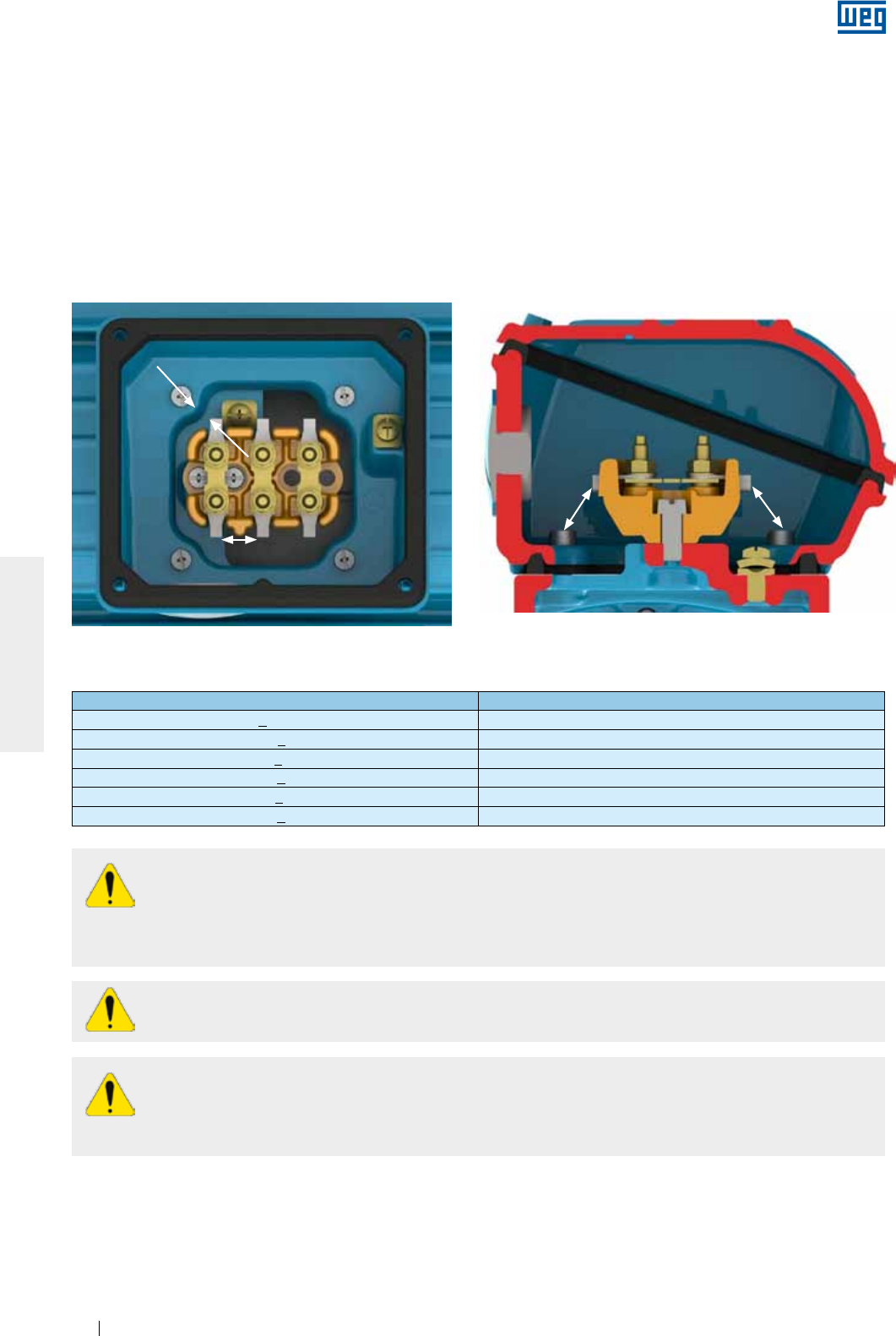
www.weg.net
Motores Eléctricos142
ESPAÑOL
Asegúrese que el motor esté conectado correctamente a la red de alimentación eléctrica a través de contactos
seguros y permanentes.
Para motores sin placa de bornes, aísle los cables terminales del motor, utilizando materiales aislantes
compatibles con la tensión de alimentación y con la clase de aislamiento informada en la placa de
identificación.
Para la conexión del cable de alimentación y del sistema de puesta a tierra deben ser respetados los torques
de apriete indicados en la Tabla 8.7.
La distancia de aislamiento (ver Figura 6.13) entre partes vivas no aisladas entre sí y entre partes vivas y partes
puestas a tierra debe respetar los valores indicados en la Tabla 6.3.
Distancia de aislamiento
Distancia de aislamiento
Distancia de aislamiento Distancia de aislamiento
Figura 6.13 - Representación de la distancia de aislamiento
Tabla 6.3 - Distancia mínima de aislamiento (mm) x tensión de alimentación
Tensión Distancia mínima de aislamiento (mm)
U < 440 V 4
440 < U < 690 V 5.5
690 < U < 1000 V 8
1000 < U < 6900 V 45
6900 < U < 11000 V 70
11000 < U < 16500 V 105
Aunque el motor esté apagado, puede existir energía eléctrica en el interior de la caja de conexión
utilizada para la alimentación de las resistencias de calentamiento o inclusive para energizar el
devanado, cuando éste esté siendo utilizado como elemento de calentamiento.
Los condensadores de motores pueden retener energía eléctrica, incluso con el motor apagado. No toque
los condensadores ni los terminales del motor sin antes verificar la existencia de tensión en los mismos.
Luego de efectuar la conexión del motor, asegúrese de que ningún cuerpo extraño haya
permanecido en el interior de la caja de conexión.
Las entradas de la(s) caja(s) de conexión deben ser cerradas/protegidas para de esa forma garantizar el
grado de protección del indicado en la placa de identificación del motor.
Las entradas de cables utilizadas para alimentación y control deben emplear componentes (como, por
ejemplo, prensacables y electroductos) que cumplan las normas y reglamentaciones vigentes en cada país.
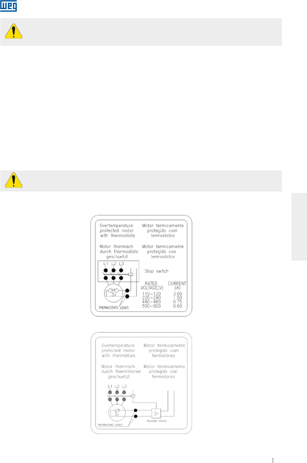
www.weg.net
Motores Eléctricos 143
ESPAÑOL
En caso que existan accesorios, como freno y ventilación forzada, los mismos deben ser
conectados a la red de alimentación, siguiendo las informaciones de sus placas de identificación y
los cuidados indicados anteriormente.
No aplique tensión de test superior a 2,5 V para termistores y corriente mayor a 1 mA para RTDs
(Pt-100) de acuerdo con la norma IEC 60751.
Todas las protecciones, inclusive las contra sobretensión, deben ser ajustadas tomando como base las
condiciones nominales de la máquina. Esta protección también tendrá que proteger el motor en caso de
cortocircuito, falta de fase, o rotor bloqueado.
Los ajustes de los dispositivos de seguridad de los motores deben ser hechos según las normas vigentes.
Verifique el sentido de rotación del motor. En caso que no haya ninguna limitación debido a la utilización de
ventiladores unidireccionales, es posible cambiar el sentido de giro de motores trifásicos, invirtiendo dos fases
de alimentación. Para motores monofásicos, verifique el esquema de conexión en la placa de identificación.
6.10. CONEXION DE LOS DISPOSITIVOS DE PROTECCION TERMICA
Cuando es suministrado con dispositivos de protección o de monitoreo de temperatura, como: protector
térmico bimetálico (termostatos), termistores, protectores térmicos del tipo Automático, Pt-100 (RTD), etc., sus
terminales deben ser conectados a los dispositivos de control correspondientes, de acuerdo con las placas de
identificación de los accesorios. La no observación de este procedimiento puede resultar en la cancelación de
la garantía y riesgo para la instalación.
El esquema de conexión de los protectores térmicos bimetálicos (termostatos) y termistores es mostrado en la
Figura 6.14 y Figura 6.15, respectivamente.
Figura 6.14 - Conexión de los protectores térmicos bimetálicos (termostatos)
Figura 6.15 - Conexión de los termistores
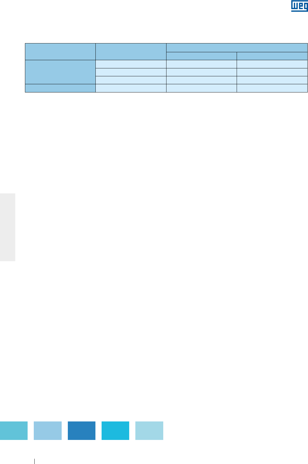
www.weg.net
Motores Eléctricos144
ESPAÑOL
Los límites de temperatura de alarma y desconexión de las protecciones térmicas pueden ser definidos de
acuerdo con la aplicación, no obstante, no deben sobrepasar los valores indicados en la Tabla 6.4.
Componente Clase de aislamiento Temperatura máxima de operación (°C)
Alarma Desconexión
Devanado
B - 130
F 130 155
H 155 180
Cojinete Todas 110 120
Tabla 6.4 - Temperatura máxima de actuación de las protecciones térmicas
Notas:
1) La cantidad y el tipo de protección térmica instalados en el motor son informados en las placas de identificación de los accesorios del
mismo.
2) En el caso de protección térmica con resistencia calibrada (por ejemplo, Pt-100), el sistema de protección debe ser ajustado a la
temperatura de operación indicada en la Tabla 6.4.
6.11. TERMORESISTORES (PT-100)
Son elementos, cuya operación está basada en la característica de variación de la resistencia con la
temperatura, intrínseca en algunos materiales (generalmente platina, níquel o cobre).
Poseen resistencia calibrada, que varía linealmente con la temperatura, posibilitando un acompañamiento
continuo del proceso de calentamiento del motor por el display del controlador, con alto grado de precisión y
sensibilidad de respuesta. Su aplicación es amplia en los diversos sectores de técnicas de medición y
automatización de temperatura de las industrias. Generalmente, se aplica en instalaciones de gran
responsabilidad como, por ejemplo, en régimen intermitente muy irregular. El mismo detector puede servir
tanto para alarma como para apagado.
La equivalencia entre la resistencia del Pt-100 y la temperatura es presentada en la Tabla 6.4 y Figura 6.16.
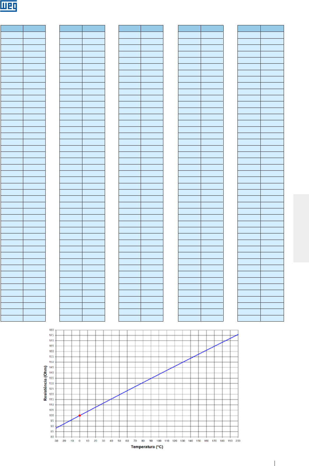
www.weg.net
Motores Eléctricos 145
ESPAÑOL
ºC ºC ºC ºC ºC
-29 88.617 17 106.627 63 124.390 109 141.908 155 159.180
-28 89.011 18 107.016 64 124.774 110 142.286 156 159.553
-27 89.405 19 107.404 65 125.157 111 142.664 157 159.926
-26 89.799 20 107.793 66 125.540 112 143.042 158 160.298
-25 90.193 21 108.181 67 125.923 113 143.420 159 160.671
-24 90.587 22 108.570 68 126.306 114 143.797 160 161.043
-23 90.980 23 108.958 69 126.689 115 144.175 161 161.415
-22 91.374 24 109.346 70 127.072 116 144.552 162 161.787
-21 91.767 25 109.734 71 127.454 117 144.930 163 162.159
-20 92.160 26 110.122 72 127.837 118 145.307 164 162.531
-19 92.553 27 110.509 73 128.219 119 145.684 165 162.903
-18 92.946 28 110.897 74 128.602 120 146.061 166 163.274
-17 93.339 29 111.284 75 128.984 121 146.438 167 163.646
-16 93.732 30 111.672 76 129.366 122 146.814 168 164.017
-15 94.125 31 112.059 77 129.748 123 147.191 169 164.388
-14 94.517 32 112.446 78 130.130 124 147.567 170 164.760
-13 94.910 33 112.833 79 130.511 125 147.944 171 165.131
-12 95.302 34 113.220 80 130.893 126 148.320 172 165.501
-11 95.694 35 113.607 81 131.274 127 148.696 173 165.872
-10 96.086 36 113.994 82 131.656 128 149.072 174 166.243
-9 96.478 37 114.380 83 132.037 129 149.448 175 166.613
-8 96.870 38 114.767 84 132.418 130 149.824 176 166.984
-7 97.262 39 115.153 85 132.799 131 150.199 177 167.354
-6 97.653 40 115.539 86 133.180 132 150.575 178 167.724
-5 98.045 41 115.925 87 133.561 133 150.950 179 168.095
-4 98.436 42 116.311 88 133.941 134 151.326 180 168.465
-3 98.827 43 116.697 89 134.322 135 151.701 181 168.834
-2 99.218 44 117.083 90 134.702 136 152.076 182 169.204
-1 99.609 45 117.469 91 135.083 137 152.451 183 169.574
0 100.000 46 117.854 92 135.463 138 152.826 184 169.943
1 100.391 47 118.240 93 135.843 139 153.200 185 170.313
2 100.781 48 118.625 94 136.223 140 153.575 186 170.682
3 101.172 49 119.010 95 136.603 141 153.950 187 171.051
4 101.562 50 119.395 96 136.982 142 154.324 188 171.420
5 101.953 51 119.780 97 137.362 143 154.698 189 171.789
6 102.343 52 120.165 98 137.741 144 155.072 190 172.158
7 102.733 53 120.550 99 138.121 145 155.446 191 172.527
8 103.123 54 120.934 100 138.500 146 155.820 192 172.895
9 103.513 55 121.319 101 138.879 147 156.194 193 173.264
10 103.902 56 121.703 102 139.258 148 156.568 194 173.632
11 104.292 57 122.087 103 139.637 149 156.941 195 174.000
12 104.681 58 122.471 104 140.016 150 157.315 196 174.368
13 105.071 59 122.855 105 140.395 151 157.688 197 174.736
14 105.460 60 123.239 106 140.773 152 158.061 198 175.104
15 105.849 61 123.623 107 141.152 153 158.435 199 175.472
16 106.238 62 124.007 108 141.530 154 158.808 200 175.840
Tabla 6.5 - Equivalencia entre la resistencia del Pt-100 y la temperatura
Figura 6.16 - Resistencia óhmica del Pt-100 x temperatura

www.weg.net
Motores Eléctricos146
ESPAÑOL
6.13. METODOS DE PARTIDA
6.12. CONEXION DE LAS RESISTENCIAS DE CALDEO
Siempre que sea posible, la partida del motor debe ser directa (en plena tensión). Es el método más simple, sin
embargo, solamente es viable cuando la corriente de partida no afecta la red de alimentación. Es importante
seguir las reglas vigentes de la concesionaria de energía eléctrica.
En los casos en que la corriente de partida del motor es alta, pueden ocurrir las siguientes consecuencias:
a) Elevada caída de tensión en el sistema de alimentación de la red, provocando interferencia en los
equipamientos instalados en este sistema;
b) El superdimensionamiento del sistema de protección (cables, contactores), lo que eleva los costos de la instalación.
En caso que la partida directa no sea posible debido a los problemas citados arriba, se puede usar el método
de partida indirecta compatible con la carga y la tensión del motor, para reducir la corriente de partida.
Cuando es utilizado un método de partida con tensión reducida, el torque de partida del motor también será
reducido.
Antes de encender las resistencias de caldeo, verifique si sus conexiones fueron realizadas de acuerdo con el
diagrama indicado en la placa de identificación de las resistencias de caldeo. Para motores suministrados con
resistencias de caldeo de doble tensión (110-127/220-240 V), ver Figura 6.17.
Figura 6.17 - Conexión de las resistencias de caldeo de doble tensión
Las resistencias de caldeo nunca deben estar energizadas mientras el motor esté operando.
Cantidad de cables Métodos de partidas posibles
3 cables Llave Compensadora
Soft-starter
6 cables
Llave Estrella - Triángulo
Llave Compensadora
Soft-starter
9 cables
Llave Serie - Paralela
Llave Compensadora
Soft-starter
12 cables
Llave Estrella - Triángulo
Llave Serie - Paralela
Llave Compensadora
Soft-starter
Tabla 6.6 - Métodos de partida - cantidad de cables
La Tabla 6.6 indica los métodos de partida indirecta posibles de ser utilizados, de acuerdo con la cantidad de
cables del motor.
La Tabla 6.7 indica ejemplos de métodos de partida indirecta posibles de ser utilizados, de acuerdo con la
tensión indicada en la placa de identificación del motor y la tensión de la red eléctrica.
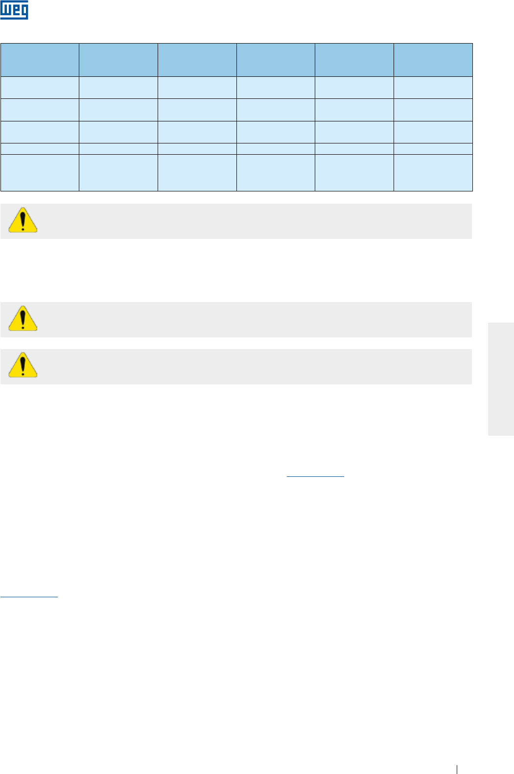
www.weg.net
Motores Eléctricos 147
ESPAÑOL
Tabla 6.7 - Métodos de partida x tensión
Tensión de la
placa de
identificación
Tensión de la red Partida con llave
Estrella - Triángulo
Partida con llave
compensadora
Partida con llave
Serie - Paralela
Partida con
Soft-starter
220/380 V 220 V
380 V
SÍ
NO
SÍ
SÍ
NO
NO
SÍ
SÍ
220/440 V 220 V
440 V
NO
NO
SÍ
SÍ
SÍ
NO
SÍ
SÍ
230/460 V 230 V
460 V
NO
NO
SÍ
SÍ
SÍ
NO
SÍ
SÍ
380/660 V 380 V SÍ SÍ NO SÍ
220/380/440 V
220 V
380 V
440 V
SÍ
NO
SÍ
SÍ
SÍ
SÍ
SÍ
SÍ
NO
SÍ
SÍ
SÍ
Los motores WQuattro deben ser accionados directamente a partir de la red o por convertidor de
frecuencia en modo escalar.
Otro método de partida posible que no sobrecargue la red de alimentación es la utilización de un convertidor
de frecuencia. Para más informaciones sobre motores alimentados con convertidor de frecuencia ver ítem 6.14.
6.14. MOTORES ALIMENTADOS POR CONVERTIDOR DE FRECUENCIA
La operación con convertidor de frecuencia debe ser informada en el momento de la compra
debido a posibles diferencias constructivas necesarias para ese tipo de accionamiento.
Los motores Wmagnet deben ser accionados solamente por convertidor de frecuencia WEG.
El convertidor utilizado para accionar motores con tensión de alimentación hasta 690V debe poseer
modulación PWM con control vectorial.
Cuando un motor opera con convertidor de frecuencia por debajo de la frecuencia nominal, es necesario
reducir el torque suministrado por el motor, a fin de evitar sobrecalentamiento. Los valores de reducción de
torque (derating torque) pueden ser encontrados en el ítem 6.4 de la “Guía Técnica Motores de Inducción
Alimentados por Convertidores de Frecuencia PWM” disponible en www.weg.net.
Para operación por encima de la frecuencia nominal debe ser observado:
g Operación con potencia constante;
g El motor puede suministrar como máximo 95% de la potencia nominal;
g Respetar la rotación máxima, considerando los siguientes criterios:
g Máxima frecuencia de operación informada en la placa adicional;
g Límite de rotación mecánica del motor.
Los recomendaciones para los cables de conexión entre motor y convertidor son indicadas en el ítem 6.8 de
la “Guía Técnica de Motores de Inducción alimentados por Convertidores de Frecuencia PWM” disponible en
www.weg.net.
6.14.1. Uso de filtros (dV/dt)
6.14.1.1. Motor con alambre circular esmaltado
Los motores con tensión nominal de hasta 690 V, cuando son alimentados por convertidores de frecuencia, no
requieren filtros, cuando son observados los criterios de abajo:
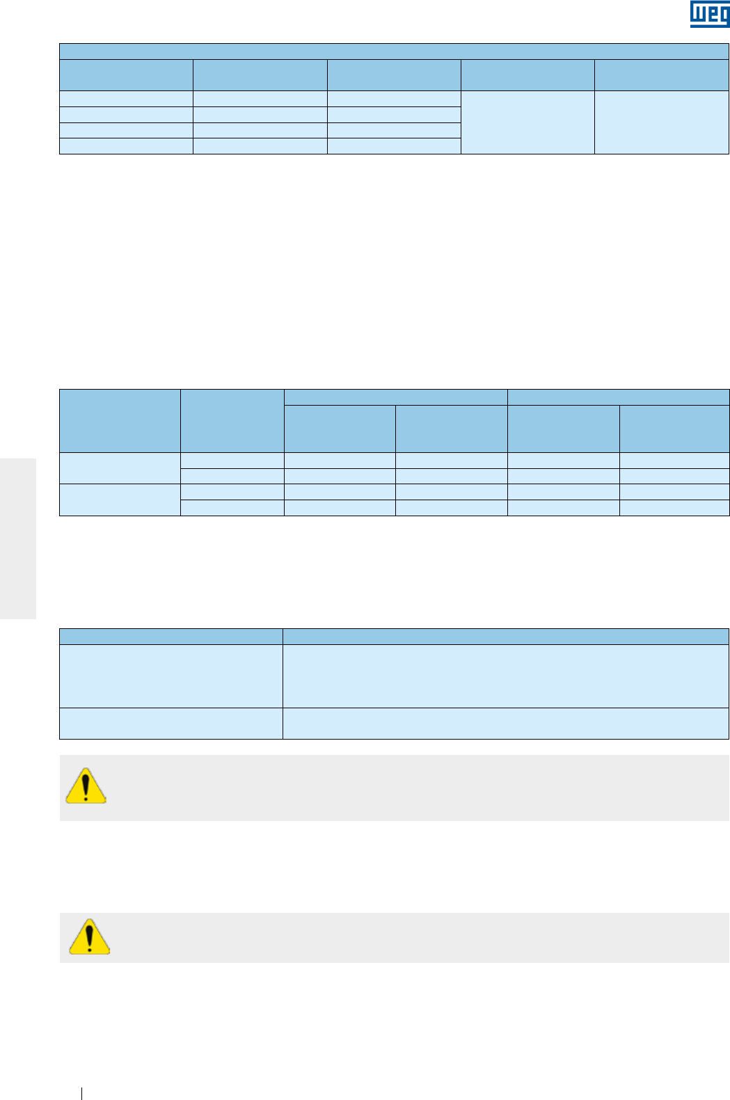
www.weg.net
Motores Eléctricos148
ESPAÑOL
Criterios para utilización de motores de alambre circular esmaltado alimentados por convertidor de frecuencia 1
Tensión de operación
del motor2
Tensión de pico en el
motor (máx.)
dV/dt en la salida del
convertidor (máx.)
Rise time3 del
convertidor (mín.)
MTBP3 tiempo entre
pulsos (min)
Vnom ≤ 460 V ≤ 1600 V ≤ 5200 V/µs
≥ 0,1 µs ≥ 6 µs
460 < Vnom ≤ 575 V ≤ 1800 V ≤ 6500 V/µs
575 < Vnom ≤ 690 V4≤ 1600 V ≤ 5200 V/µs
575 < Vnom ≤ 690 V5≤ 2200 V ≤ 7800 V/µs
1. Para motores con alambre circular esmaltado con tensión 690 < Vnom ≤ 1100 V, consulte a WEG.
2. Para motores con doble tensión, ejemplo 380/660 V, deben ser observados los criterios de la tensión menor
(380 V).
3. Informaciones suministradas por el fabricante del convertidor.
4. Cuando no es informado en el momento de la compra que el motor operará con convertidor de frecuencia.
5. Cuando es informado en el momento de la compra que el motor operará con convertidor de frecuencia.
6.14.1.2. Motor con bobina preformada
Los motores con bobina preformada (media y alta tensión, independientemente del tamaño de la carcasa y
baja tensión a partir de la carcasa IEC 500 / NEMA 80) especificados para utilización con convertidor de
frecuencia no requieren filtros, si son observados los criterios de la Tabla 6.8.
Para motores suministrados con sistema de puesta a tierra del eje, debe ser observado
constantemente el estado de conservación de la escobilla y, al llegar al fin de su vida útil, la misma
debe ser sustituida por otra de su misma especificación.
La no observación de los criterios y recomendaciones expuestos en este manual puede resultar en
la anulación de la garantía del producto.
Tabla 6.8 - Criterios para utilización de motores con bobina preformada alimentados con convertidor de frecuencia
Tensión de
operación del motor
Tipo de
modulación
Aislamiento de la espira (fase-fase) Aislamiento principal (fase-tierra)
Tensión de pico en
los terminales del
motor
dV/dt en los
terminales del
motor
Tensión de pico en
los terminales del
motor
dV/dt en los
terminales del
motor
690 < Vnom ≤ 4160 V Senoidal ≤ 5900 V ≤ 500 V/µs ≤ 3400 V ≤ 500 V/µs
PWM ≤ 9300 V ≤ 2700 V/µs ≤ 5400 V ≤ 2700 V/µs
4160 < Vnom ≤ 6600 V Senoidal ≤ 9300 V ≤ 500 V/µs ≤ 5400 V ≤ 500 V/µs
PWM ≤ 14000 V ≤ 1500 V/µs ≤ 8000 V ≤ 1500 V/µs
6.14.2. Aislamiento de los cojinetes
Como modelo, solamente motores en carcasa IEC 400 (NEMA 68) y superiores son suministrados con cojinete
aislado. Se recomienda aislar los cojinetes para operación con convertidor de frecuencia de acuerdo con la
Tabla 6.9.
Tabla 6.9 - Recomendación sobre el aislamiento de los cojinetes para motores accionados por convertidor de frecuencia
Carcasa Recomendación
IEC 315 e 355
NEMA 445/7, 447/9, L447/9, 504/5,
5006/7/8, 5009/10/11, 586/7, 5807/8/9,
5810/11/12 e 588/9
Un cojinete aislado
Puesta a tierra entre eje y carcasa por medio de escobilla
IEC 400 y superior
NEMA 6800 y superior
Cojinete trasero aislado
Puesta a tierra entre eje y carcasa por medio de escobilla
6.14.3. Frecuencia de conmutación
La frecuencia mínima de conmutación del convertidor deberá ser de 2,5 kHz.
Se recomienda que la frecuencia máxima de conmutación del convertidor sea de 5 kHz.
6.14.4. Límite de la rotación mecánica
La Tabla 6.10 muestra las rotaciones máximas permitidas para motores accionados por convertidor de
frecuencia.
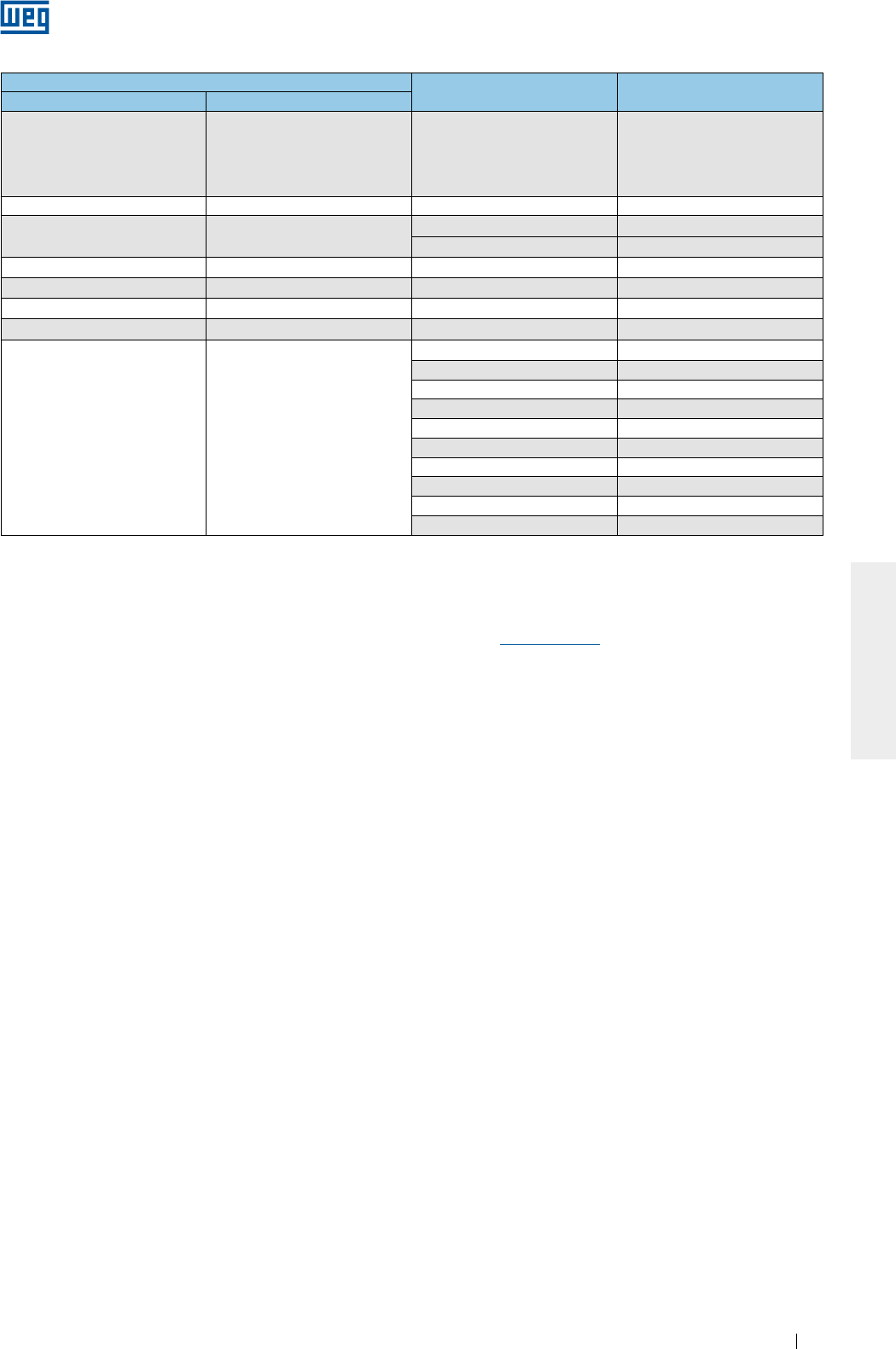
www.weg.net
Motores Eléctricos 149
ESPAÑOL
Tabla 6.10 - Rotación máxima del motor (en RPM)
Nota: para seleccionar la rotación máxima permitida para el motor, considere la curva de reducción de torque del motor.
Para más informaciones sobre el uso de convertidor de frecuencia, o acerca de cómo dimensionarlo
correctamente para su aplicación, favor contacte a WEG o consulte la “Guía Técnica de Motores de Inducción
Alimentados por Convertidores de Frecuencia PWM” disponible en www.weg.net.
Carcasa Rodamiento delantero Rotación máxima para
motores estándar
IEC NEMA
63-90 143/5
6201
6202
6203
6204
6205
10400
100 - 6206 8800
112 182/4 6207 7600
6307 6800
132 213/5 6308 6000
160 254/6 6309 5300
180 284/6 6311 4400
200 324/6 6312 4200
225-630 364/5-9610
6314 3600
6315 3600
6316 3200
6319 3000
6220 3600
6320 2200
6322 1900
6324 1800
6328 1800
6330 1800
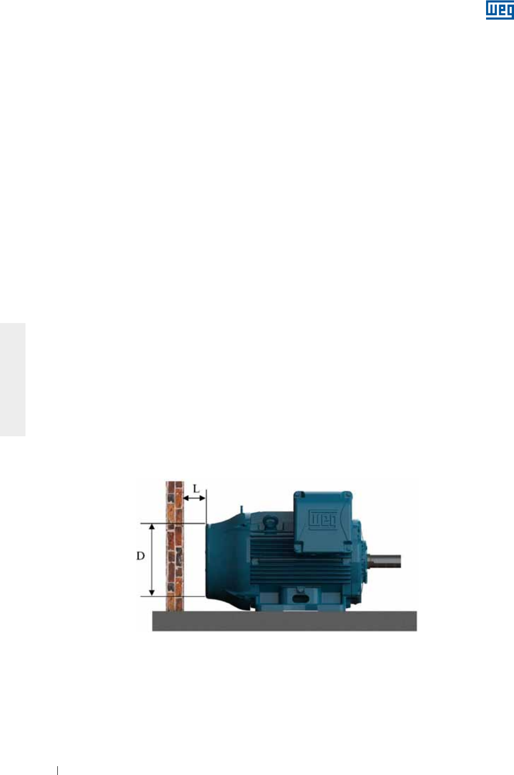
www.weg.net
Motores Eléctricos150
ESPAÑOL
7. OPERACION
7.1. PARTIDA DEL MOTOR
Luego de ejecutar los procedimientos de instalación, algunos aspectos deben ser verificados antes de la
partida inicial del motor, principalmente si el motor no fue colocado inmediatamente en operación tras su
instalación. Aquí deben ser verificados los siguientes ítems:
g Si los datos que constan en la placa de identificación (tensión, corriente, esquema de conexión, grado de
protección, refrigeración, factor de servicio, entre otras) están de acuerdo con la aplicación;
g El correcto montaje y alineamiento del conjunto (motor + máquina accionada);
g El sistema de accionamiento del motor, considerando que la rotación del motor no sobrepase la velocidad
máxima establecida en la Tabla 6.10;
g La resistencia de aislamiento del motor, conforme ítem 5.4;
g El sentido de rotación del motor;
g La integridad de la caja de conexión, que debe estar limpia y seca, sus elementos de contacto libres de
oxidación, sus sellados en condiciones apropiadas de uso y sus entradas de cables correctamente
cerradas/protegidas de acuerdo con el grado de protección.
g Las conexiones del motor, verificando si fueron correctamente realizadas, inclusive puesta a tierra y cables
auxiliares, conforme recomendaciones del ítem 6.9;
g El correcto funcionamiento de los accesorios (freno, encoder, protección térmica, ventilación forzada, etc.)
instalados en el motor;
g La condición de los rodamientos. Si presentan señales de oxidación, deben ser substituidos. En caso que no
presenten oxidación, realice el procedimiento de relubricación conforme descrito en el ítem 8.2. Aquellos
motores instalados hace más de dos años, que no entraron en operación, deben tener sus rodamientos
substituidos antes de ser puestos en operación.;
g En motores con cojinetes de deslizamiento debe ser verificado:
g El nivel correcto de aceite del cojinete. El mismo debe estar en la mitad del visor (ver Figura 6.8);
g Que el motor no parta ni opere con cargas radiales o axiales;
g Que cuando el motor sea almacenado por un período igual o mayor al intervalo de cambio de aceite, el
aceite deberá ser cambiado antes de la puesta en funcionamiento.
g El análisis de la condición de los condensadores, si existen. Para motores instalados por un período superior
a dos años, pero que no entraron en operación, se recomienda la substitución de sus condensadores de
partida de motores monofásicos;
g Que entradas y salidas de aire estén completamente desobstruidas. El mínimo espacio libre hasta la pared
más próxima (L) debe ser ¼ del diámetro de la entrada de aire de la deflectora (D), ver Figura 7.1. El aire en la
entrada del motor debe estar a temperatura ambiente.
Figura 7.1 - Distancia mínima del motor hasta la pared
Como referencia, pueden ser seguidas las distancias mínimas presentadas en la Tabla 7.1.
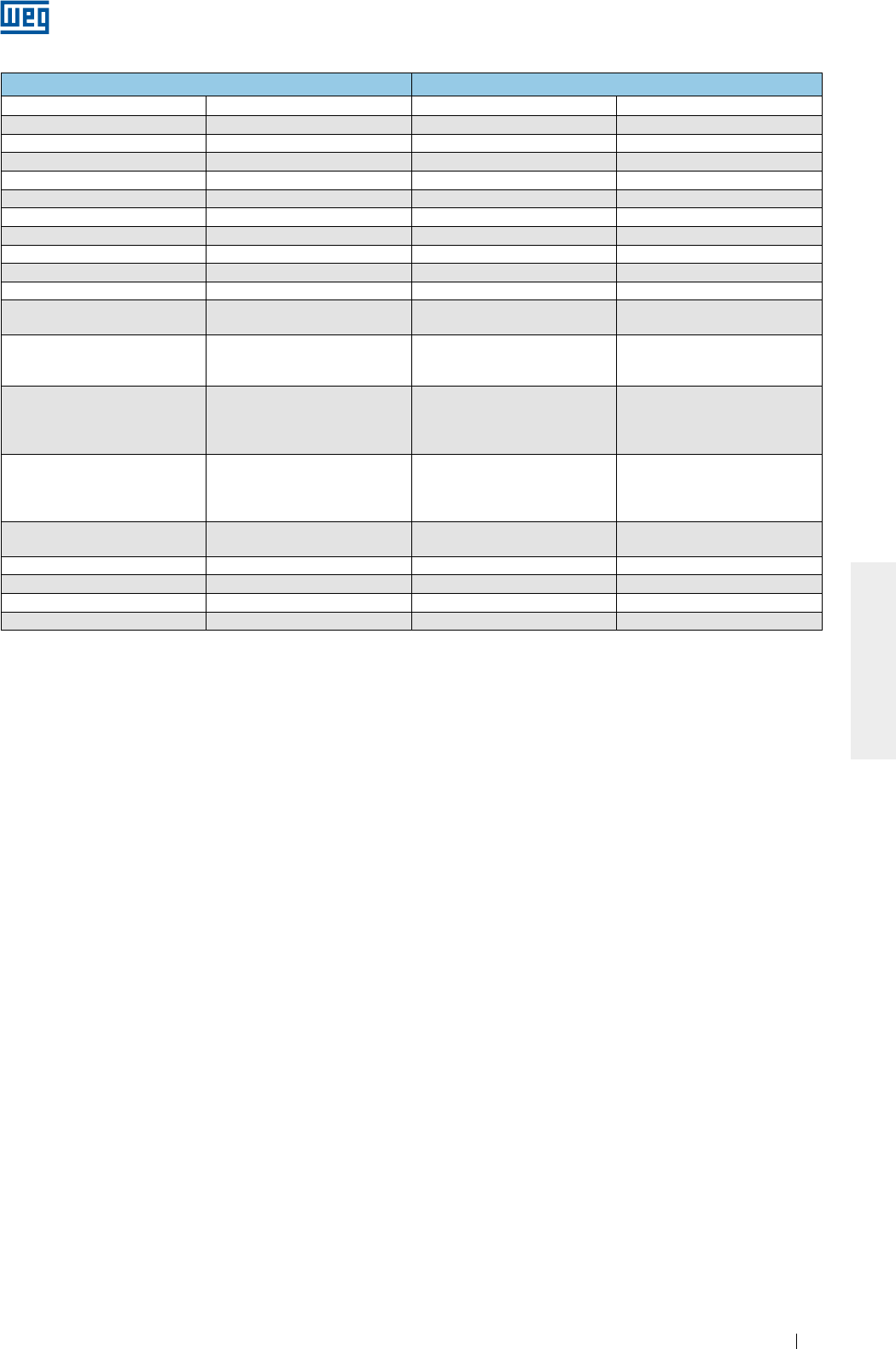
www.weg.net
Motores Eléctricos 151
ESPAÑOL
Tabla 7.1 - Distancia mínima entre la tapa deflectora y la pared
g Que los flujos y las temperaturas del agua estén correctas, cuando es utilizada en la refrigeración del motor.
Ver ítem 7.2;
g Que todas las partes giratorias, como poleas, acoplamientos, ventiladores externos, eje, etc., estén
protegidas contra toques accidentales.
Otros testes y verificaciones que no constan en esta relación pueden hacerse necesarios, en función de las
características específicas de la instalación, aplicación y/o del motor.
Luego de haber sido realizadas todas las verificaciones, siga el procedimiento de abajo para efectuar la partida
de motor:
g Encienda la máquina sin ninguna carga (cuando sea posible), accionando la llave de partida como si fuese un pulso,
verificando el sentido de rotación, la presencia de ruido, vibración u otra condición anormal de operación;
g Encienda nuevamente el motor, debiendo partir y funcionar de manera suave. En caso que eso no ocurra,
apáguelo y verifique nuevamente el sistema de montaje y las conexiones antes de una nueva partida;
g En caso de vibraciones excesivas, verifique si los tornillos de fijación están adecuadamente apretados o si la
vibración es proveniente de máquinas adyacentes. Verifique periódicamente la vibración, respetando los
límites presentados en el ítem 7.2.1;
g Opere el motor bajo carga nominal por un pequeño período de tiempo y compare la corriente de operación
con la corriente indicada en la placa de identificación;
g Se recomienda que algunas variables del motor sean acompañadas hasta su equilibrio térmico: corriente,
tensión, temperatura en los cojinetes y en la superficie externa de la carcasa, vibración y ruido;
g Se recomienda que los valores de corriente y tensión sean registrados en el informe de instalación.
Debido al valor elevado de la corriente de partida de los motores de inducción, el tiempo gastado en la
aceleración en las cargas de inercia apreciable resulta en la elevación rápida de la temperatura del motor. Si el
intervalo entre partidas sucesivas es muy reducido, resultará en un aumento de la temperatura en los
devanados, damnificándolos o reduciendo su vida útil. En caso que no sea especificado régimen de servicio
diferente a S1 / CONT. en la placa de identificación del motor, los motores están aptos para:
g Dos partidas sucesivas, siendo la primera hecha con el motor frío, es decir, con sus devanados a
temperatura ambiente y una segunda partida a seguir, no obstante, luego que el motor haya sido
desacelerado hasta alcanzar su reposo;
g Una partida con el motor a caliente, o sea, con los devanados a la temperatura de régimen.
El ítem 10 lista algunos problemas de mal funcionamiento del motor, con sus posibles causas.
Carcasa Distancia entre la tapa deflectora y la pared (L)
IEC NEMA mm pulgadas
63 - 25 0,96
71 - 26 1,02
80 - 30 1,18
90 143/5 33 1,30
100 - 36 1,43
112 182/4 41 1,61
132 213/5 50 1,98
160 254/6 65 2,56
180 284/6 68 2,66
200 324/6 78 3,08
225
250
364/5
404/5 85 3,35
280
444/5
445/7
447/9
108 4,23
315
L447/9
504/5
5006/7/8
5009/10/11
122 4,80
355
586/7
588/9
5807/8/9
5810/11/12
136 5,35
400 6806/7/8
6809/10/11 147 5,79
450 7006/10 159 6,26
500 8006/10 171 6,73
560 8806/10 185 7,28
630 9606/10 200 7,87
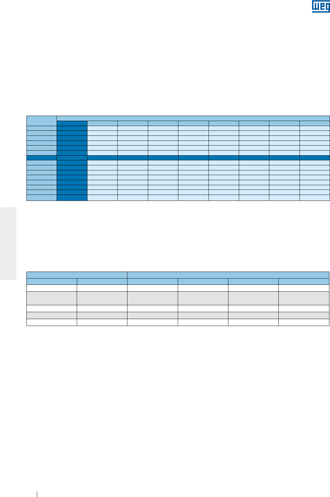
www.weg.net
Motores Eléctricos152
ESPAÑOL
T (°C) Altitud (m)
1000 1500 2000 2500 3000 3500 4000 4500 5000
10 0,97 0,92 0,88
15 0,98 0,94 0,90 0,86
20 1,00 0,95 0,91 0,87 0,83
25 1,00 0,95 0,93 0,89 0,85 0,81
30 1,00 0,96 0,92 0,90 0,86 0,82 0,78
35 1,00 0,95 0,93 0,90 0,88 0,84 0,80 0,75
40 1,00 0,97 0,94 0,90 0,86 0,82 0,80 0,76 0,71
45 0,95 0,92 0,90 0,88 0,85 0,81 0,78 0,74 0,69
50 0,92 0,90 0,87 0,85 0,82 0,80 0,77 0,72 0,67
55 0,88 0,85 0,83 0,81 0,78 0,76 0,73 0,70 0,65
60 0,83 0,82 0,80 0,77 0,75 0,73 0,70 0,67 0,62
65 0,79 0,76 0,74 0,72 0,70 0,68 0,66 0,62 0,58
70 0,74 0,71 0,69 0,67 0,66 0,64 0,62 0,58 0,53
75 0,70 0,68 0,66 0,64 0,62 0,60 0,58 0,53 0,49
80 0,65 0,64 0,62 0,60 0,58 0,56 0,55 0,48 0,44
7.2. CONDICIONES DE OPERACION
En caso que ninguna otra condición sea informada en el momento de la compra, los motores eléctricos son
proyectados para operar a una altitud limitada a 1000 m por encima del nivel del mar y en temperatura
ambiente entre -20 °C y +40 °C. Cualquier variación de las condiciones del ambiente, donde el motor operará,
debe estar indicada en la placa de identificación del motor.
Algunos componentes precisan ser cambiados, cuando la temperatura ambiente es diferente de la indicada
arriba. Favor contactar a WEG para verificar las características especiales.
Para temperaturas y altitudes diferentes de las indicadas arriba, utilizar la Tabla 7.2 para encontrar el factor de
corrección que deberá ser utilizado para definir la potencia útil disponible (Pmax = Pnom x Factor de
corrección).
El ambiente en el local de instalación deberá tener condiciones de renovación de aire del orden de 1 m³ por
segundo para cada 100 kW o fracción de potencia del motor. Para motores ventilados, que no poseen
ventilador propio, la ventilación adecuada del motor es de responsabilidad del fabricante del equipamiento. En
caso que no haya especificación de la velocidad de aire mínima entre las aletas del motor en una placa de
identificación, deben ser seguidos los valores indicados en la Tabla 7.3. Los valores presentados en la Tabla 7.3
son válidos para motores aleteados alimentados en la frecuencia de 60 Hz. Para obtención de las velocidades
mínimas de aire en 50 Hz se deben multiplicar los valores de la tabla por 0,83.
Tabla 7.3 - Velocidad mínima de aire entre las aletas del motor (m/s)
Tabla 7.2 - Factores de corrección considerando la altitud y la temperatura ambiente
Carcasa Polos
IEC NEMA 2 4 6 8
63 a 90 143/5 14 7 5 4
100 a 132 182/4 y
213/5 18 10 8 6
160 a 200 364/5 to 444/5 20 20 12 7
225 a 280 364/5 to 444/5 22 22 18 12
315 a 355 445/7 to 588/9 25 25 20 15
Las variaciones de la tensión y frecuencia de alimentación pueden afectar las características de desempeño y
la compatibilidad electromagnética del motor. Estas variaciones de alimentación deben seguir los valores
establecidos en las normas vigentes. Ejemplos:
g ABNT NBR 17094 - Partes 1 y 2. El motor está apto para proveer torque nominal, bajo las siguientes zonas
de variación de tensión y frecuencia:
g Zona A: 5% de tensión y 2% de frecuencia;
g Zona B: 10% de tensión y +3% -5% de frecuencia.
Cuando es operado en la Zona A o B, el motor puede presentar variaciones de desempeño y alcanzar
temperaturas más elevadas. Estas variaciones son mayores para la operación en la zona B. No es
recomendada una operación prolongada del motor en la zona B.
g IEC 60034-1. El motor está apto para proveer torque nominal, bajo las siguientes zonas de variación de
tensión y frecuencia:
g Zona A: 5% de tensión y 2% de frecuencia;
g Zona B: 10% de tensión y +3% -5% de frecuencia.
Cuando es operado en la Zona A o B, el motor puede presentar variaciones de desempeño y alcanzar
temperaturas más elevadas. Estas variaciones son mayores para la operación en la zona B. No es
recomendada la operación prolongada del motor en la zona B. Para motores multitensión (ejemplo 380-
415/660 V) es permitida una variación de tensión de 5%.
g NEMA MG 1 Parte 12. El motor está apto para operar en una de las siguientes variaciones:
g 10% de tensión, con frecuencia nominal;
g 5 de frecuencia, con tensión nominal;
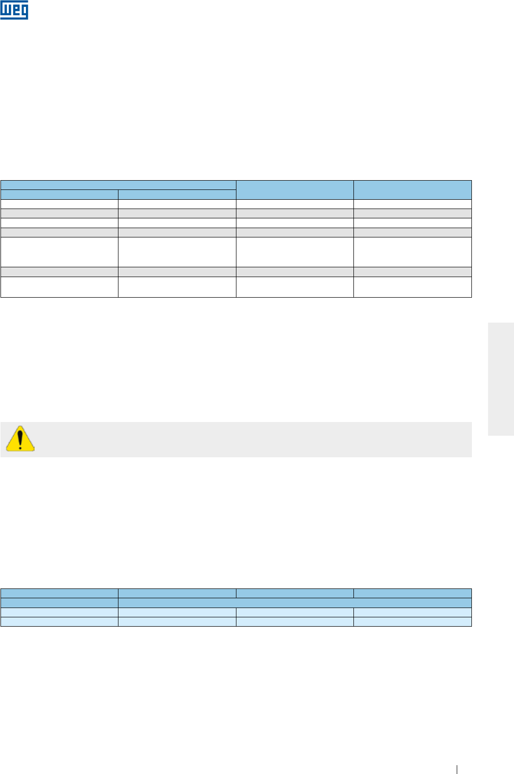
www.weg.net
Motores Eléctricos 153
ESPAÑOL
Tabla 7.4 - Flujo y máxima elevación de temperatura del agua
Carcasa Flujo
(litros/minuto)
Máxima elevación de
temperatura del agua (°C)
IEC NEMA
180 284/6 12 5
200 324/6 12 5
225 364/5 12 5
250 404/5 12 5
280
444/5
445/7
447/9
15 6
315 504/5 16 6
355 586/7
588/9 25 6
Para motores con lubricación de tipo Oil Mist, en caso de falla del sistema de bombeo de aceite, es permitida
una operación en régimen continuo con el tiempo máximo de una hora de operación.
Considerando que el calor del sol causa aumento de la temperatura de operación, los motores instalados
externamente deben siempre estar protegidos contra la incidencia directa de los rayos solares.
Posibles desvíos en relación a la operación normal (actuación de protecciones térmicas, aumento del nivel de
ruido, vibración, temperatura y corriente) deben ser examinados y eliminados por personal capacitado. En caso
de dudas, apague el motor inmediatamente y contacte a un Asistente Técnico Autorizado WEG.
Motores equipados con rodamiento de rodillos necesitan de una carga radial mínima para asegurar
su operación normal. En caso de dudas, contacte a WEG.
7.2.1. Límites de la severidad de vibración
La severidad de vibración es el máximo valor de vibración encontrada, entre todos los puntos y direcciones
recomendados.
La Tabla 7.5 indica los valores admisibles de la severidad de vibración recomendados en la norma IEC 60034-
14 para las carcasas IEC 56 a 400, para los grados de vibración A y B.
Los límites de severidad de la Tabla 7.5 son presentados en términos del valor medio cuadrático (= valor RMS o
valor eficaz) de la velocidad de vibración en mm/s medidos en condición de suspensión libre (base elástica).
Tabla 7.5 - Limites recomendados para la severidad de vibración de acuerdo con la norma IEC 60034-14
Altura del eje [mm] 56 ≤ H ≤ 132 132 < H ≤ 280 H > 280
Grado de vibración Severidad de vibración en base elástica [mm/s RMS]
A 1,6 2,2 2,8
B 0,7 1,1 1,8
Notas:
1 - Los valores de la Tabla 7.5 son válidos para mediciones realizadas con la máquina desacoplada y sin carga, operando en la
frecuencia y tensión nominales.
2 - Los valores de la Tabla 7.5 son válidos independientemente del sentido de rotación de la máquina.
3 - La Tabla 7.5 no se aplica para motores trifásicos con conmutador, motores monofásicos, motores trifásicos con alimentación
monofásica o para máquinas fijadas en el local de instalación, acopladas en sus cargas de accionamiento o cargas accionadas.
Para motor estándar, de acuerdo con la norma NEMA MG 1, el límite de vibración es de 0.15 in/s (pulgadas/
segundo pico), en la misma condición de suspensión libre y desacoplado.
Nota:
Para condición de operación en carga se recomienda el uso de la norma ISO 10816-3 para evaluación de los limites de vibración del motor.
En la condición en carga, la vibración del motor será influenciada por varios factores, entre ellos, tipo de carga acoplada, condición de
fijación del motor, condición de alineamiento con la carga, vibración de la estructura o base debido a otros equipamientos, etc..
g Una combinación de variación de tensión y frecuencia de 10%, desde que la variación de frecuencia
no sea superior a 5%..
Para motores que son enfriados a través del aire ambiente, las entradas y salidas de aire deben ser limpiadas
en intervalos regulares para garantizar una libre circulación del aire. El aire caliente no debe retornar hacia el
motor. El aire utilizado para refrigeración del motor debe estar a temperatura ambiente, limitada a la franja de
temperatura indicada en la placa de identificación del motor (cuando no sea indicado, considere una franja
de temperatura entre -20 °C y +40 °C).
Para motores refrigerados a agua, los valores del flujo de agua para cada tamaño de carcasa, así como la
máxima elevación de temperatura del agua luego de circular por el motor, son mostrados en la Tabla 7.4. La
temperatura del agua en la entrada no debe exceder 40 °C.
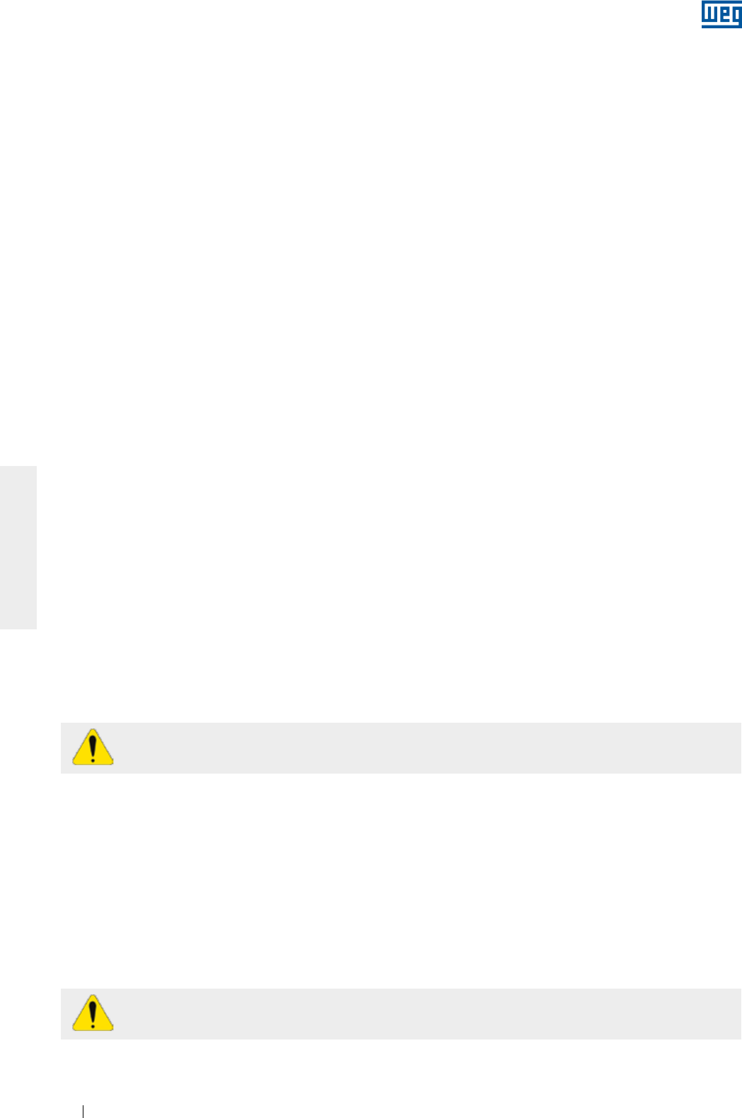
www.weg.net
Motores Eléctricos154
ESPAÑOL
8. MANTENIMIENTO
La finalidad del mantenimiento es prolongar lo máximo posible la vida útil del equipamiento. La no observancia
de uno de los ítems relacionados a seguir puede llevar a paradas no deseadas del equipamiento.
En caso que, durante el mantenimiento, hubiera necesidad de transporte de los motores con rodamientos de
rodillos o contacto angular, deben ser utilizados los dispositivos de trabado del eje suministrados con el motor.
Todos los motores HGF, independientemente del tipo de cojinete, deben ter su eje trabado durante el transporte.
Cualquier servicio en máquinas eléctricas debe ser realizado solamente por personal capacitado, utilizando
sólo herramientas y métodos adecuados. Antes de iniciar cualquier servicio, las máquinas deben estar
completamente paradas y desconectadas de la red de alimentación, inclusive los accesorios (resistencia de
calentamiento, freno, etc.).
Asistentes técnicos o personal no capacitado, sin autorización para hacer mantenimiento y/o reparar motores,
son totalmente responsables por el trabajo ejecutado y por los eventuales daños que puedan ocurrir durante
su funcionamiento.
8.1. INSPECCION GENERAL
La frecuencia con que deben ser realizadas las inspecciones depende del tipo de motor, de la aplicación y de
las condiciones del local de la instalación. Durante la inspección, se recomienda:
g Hacer una inspección visual del motor y del acoplamiento, observando los niveles de ruido, de la vibración,
alineamiento, señales de desgastes, oxidación y piezas damnificadas. Substituir las piezas, cuando fuera
necesario;
g Medir la resistencia de aislamiento conforme descrito en el ítem 5.4;
g Mantener la carcasa limpia, eliminando toda acumulación de aceite o de polvo en la parte externa del motor
para de esta forma facilitar el intercambio de calor con el medio ambiente;
gVerificar la condición del ventilador y de las entradas y salidas de aire, asegurando un libre flujo del arie;
gVerificar el estado de los sellados y efectuar el cambio, si fuera necesario;
g
Drenar el motor. Tras el drenaje, recolocar los drenajes para garantizar nuevamente el grado de protección del
motor. Los drenajes deben estar siempre posicionados de tal forma que el drenaje sea facilitado (ver ítem 6);
g Verificar la conexión de los cables de alimentación, respetando las distancias de aislamiento entre partes
vivas no aisladas entre sí y entre partes vivas y partes puestas a tierra de acuerdo con la Tabla 6.3;
g
Verificar si el apriete de los tornillos de conexión, sustentación y fijación está de acuerdo con lo indicado en la
Tabla 8.7;
g Verificar el estado del pasaje de los cables en la caja de conexión, los sellados de los prensacables y los
sellados en las cajas de conexión y efectuar el cambio, se fuera necesario;
g
Verificar el estado de los cojinetes, observando la aparición de ruidos y niveles de vibración no habituales,
verificando la temperatura de los cojinetes, el nivel del aceite, la condición del lubricante y el monitoreo de las
horas de operación versus la vida útil informada;
gRegistrar y archivar todas las modificaciones realizadas en el motor.
No reutilice piezas dañadas o desgastadas. Substitúyalas por nuevas, originales de fábrica.
La utilización de motor en ambientes y/o aplicaciones especiales siempre requiere una consulta
previa a WEG.
8.2. LUBRICACION
La correcta lubricación es de vital importancia para el buen funcionamiento del motor.
Utilice el tipo y cantidad de grasa o aceite especificados y seguir los intervalos de relubricación recomendados
para los cojinetes. Estas informaciones pueden ser encontradas en la placa de identificación y este
procedimiento debe ser realizado conforme el tipo de lubrificante (aceite o grasa).
Cuando el motor utilice protección térmica en el cojinete, deben ser respetados los límites de temperatura de
operación indicados en la Tabla 6.4.
Los motores para aplicaciones especiales pueden presentar temperaturas máximas de operación diferentes a
las indicadas en la tabla.
El descarte de la grasa y/o aceite debe seguir las recomendaciones vigentes de cada país.
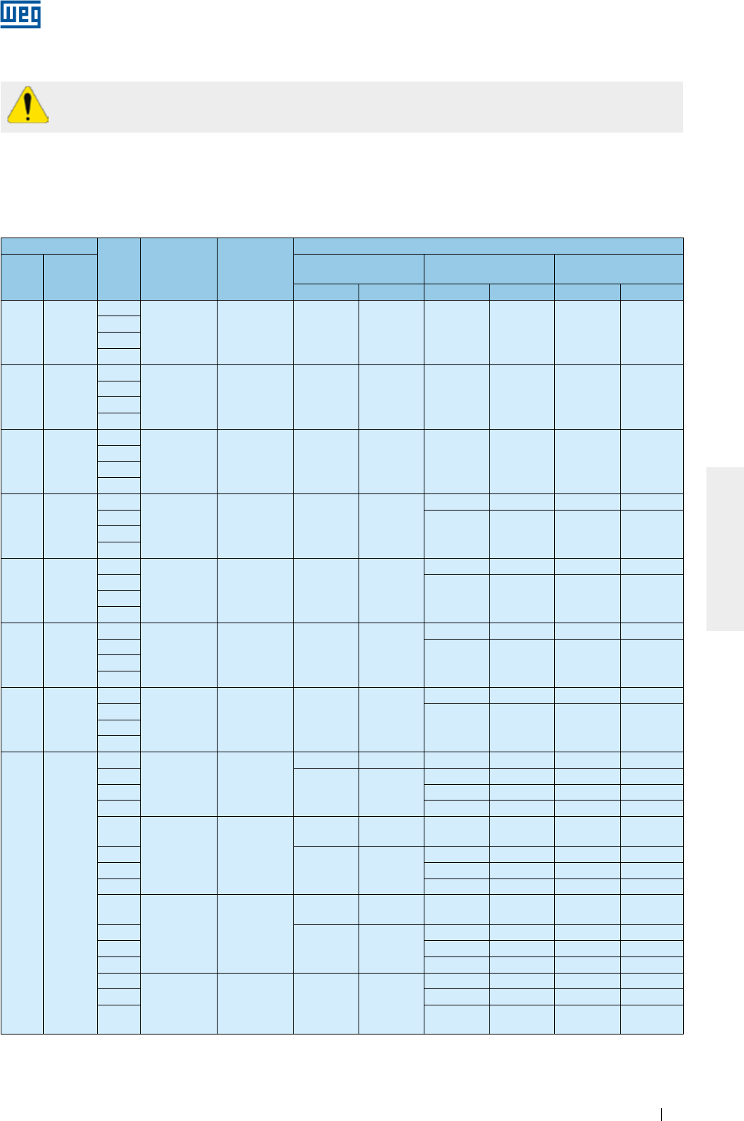
www.weg.net
Motores Eléctricos 155
ESPAÑOL
Grasa en exceso provoca calentamiento del cojinete y su consecuente falla.
8.2.1. Cojinetes de rodamiento lubricados a grasa
Los intervalos de lubricación especificados en las Tabla 8.1, Tabla 8.2, Tabla 8.3 y Tabla 8.4 consideran una
temperatura absoluta del cojinete de 70 °C (hasta carcasa IEC 200 / NEMA 324/6) y 85 °C (a partir de la
carcasa IEC 225 / NEMA 364/5), rotación nominal del motor, instalación horizontal y grasa Mobil Polyrex EM.
Cualquier variación de los parámetros indicados arriba debe ser evaluada puntualmente.
Tabla 8.1- Intervalo de lubricación para rodamientos de esferas
Carcasa
Polos Rodamiento Cantidad de
grasa (g)
Intervalos de relubricación (horas)
IEC NEMA
ODP
(Carcasa abierta)
W21
(Carcasa cerrada)
W22
(Carcasa cerrada)
50 Hz 60 Hz 50 Hz 60 Hz 50 Hz 60 Hz
90 143/5
2
6205 4 - - 20000 20000 25000 25000
4
6
8
100 -
2
6206 5 - - 20000 20000 25000 25000
4
6
8
112 182/4
2
6207/
6307 9 - - 20000 20000 25000 25000
4
6
8
132 213/5
2
6308 11 - -
20000 18400 25000 23200
4
20000 20000 25000 250006
8
160 254/6
2
6309 13 20000 20000
18100 15700 22000 20000
4
20000 20000 25000 250006
8
180 284/6
2
6311 18 20000 20000
13700 11500 17000 14000
4
20000 20000 25000 250006
8
200 324/6
2
6312 21 20000 20000
11900 9800 15000 12000
4
20000 20000 25000 250006
8
225
250
280
315
355
364/5
404/5
444/5
445/7
447/9
L447/9
504/5
5008
5010/11
586/7
588/9
2
6314 27
18000 14400 4500 3600 5000 4000
4
20000 20000
11600 9700 14000 12000
6 16400 14200 20000 17000
8 19700 17300 24000 20000
2
6316 34
14000 *Mediante
consulta 3500 *Mediante
consulta 4000 *Mediante
consulta
4
20000 20000
10400 8500 13000 10000
6 14900 12800 18000 16000
8 18700 15900 20000 20000
2
6319 45
9600 *Mediante
consulta 2400 *Mediante
consulta 3000 *Mediante
consulta
4
20000 20000
9000 7000 11000 8000
6 13000 11000 16000 13000
8 17400 14000 20000 17000
4
6322 60 20000 20000
7200 5100 9000 6000
6 10800 9200 13000 11000
8 15100 11800 19000 14000

www.weg.net
Motores Eléctricos156
ESPAÑOL
Tabla 8.2- Intervalo de lubricación para rodamientos de rodillos
Carcasa Polos Rodamiento Cantidad de
grasa (g)
Intervalos de relubricación (horas)
ODP
(Carcasa abierta)
W21
(Carcasa cerrada)
W22
(Carcasa cerrada)
IEC NEMA 50 Hz 60 Hz 50 Hz 60 Hz 50 Hz 60 Hz
160 254/6
2
NU309 13 20000
19600 13300 9800 16000 12000
4
20000 20000 20000 25000 250006
8
180 284/6
2
NU311 18
18400 12800 9200 6400 11000 8000
4
20000 20000 20000
19100
25000 250006 20000
8
200 324/6
2
NU312 21
15200 10200 7600 5100 9000 6000
4
20000 20000 20000
17200
25000
21000
620000 25000
8
"225
250
280
315
355"
364/5
404/5
444/5
445/7
447/9
L447/9
504/5
5008
5010/11
586/7
588/9
4
NU314 27
17800 14200 8900 7100 11000 9000
620000 20000 13100 11000 16000 13000
8 16900 15100 20000 19000
4
NU316 34
15200 12000 7600 6000 9000 7000
620000 19000 11600 9500 14000 12000
8 20000 15500 13800 19000 17000
4
NU319 45
12000 9400 6000 4700 7000 5000
6 19600 15200 9800 7600 12000 9000
8 20000 20000 13700 12200 17000 15000
4
NU322 60
8800 6600 4400 3300 5000 4000
6 15600 11800 7800 5900 9000 7000
8 20000 20000 11500 10700 14000 13000
Tabela 8.3 - Intervalo de lubricación para rodamiento de esferas - línea HGF.
Carcasa Polos Rodamiento Cantidad de
grasa (g)
Intervalos de Lubricación (horas)
IEC NEMA 50 Hz 60 Hz
315L/A/B y
315C/D/E
5006/7/8T y
5009/10/11T
2 6314 27 3100 2100
4 - 8 6320 50 4500 4500
6316 34 4500 4500
355L/A/B y
355C/D/E
5807/8/9T y
5810/11/12T
2 6314 27 3100 2100
4 - 8 6322 60 4500 4500
6319 45 4500 4500
400L/A/B y
400 C/D/E
6806/7/8T y
6809/10/11T
2 6315 30 2700 1800
4 - 8 6324 72 4500 4500
6319 45 4500 4500
450 7006/10
2 6220 31 2500 1400
46328 93 4500 3300
6322 60 4500 4500
6 - 8 6328 93 4500 4500
6322 60 4500 4500
500 8006/10
46330 104 4200 2800
6324 72 4500 4500
6 - 8 6330 104 4500 4500
6324 72 4500 4500
500 8006/10
46330 104 4200 2800
6324 72 4500 4500
6 - 8 6330 104 4500 4500
6324 72 4500 4500
560 8806/10 4 - 8 *Mediante consulta
630 9606/10 4 - 8
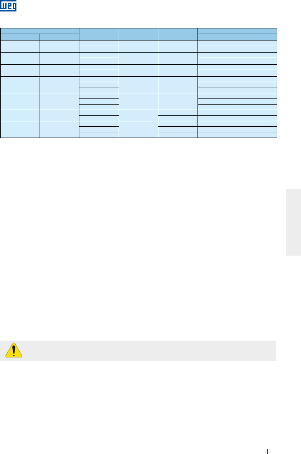
www.weg.net
Motores Eléctricos 157
ESPAÑOL
Tabla 8.4 - Intervalo de lubricación para rodamiento de rodillos - línea HGF
Carcasa Polos Rodamiento Cantidad de
grasa (g)
Intervalos de lubricación (horas)
IEC NEMA 50 Hz 60 Hz
315L/A/B y
315C/D/E
5006/7/8 y
5009/10/11
4NU320 50 4300 2900
6 - 8 4500 4500
355L/A/B y
355C/D/E
5807/8/9 y
5810/11/12
4NU322 60 3500 2200
6 - 8 4500 4500
400L/A/B y
400C/D/E
6806/7/8 y
6809/10/11
4NU324 72 2900 1800
6 - 8 4500 4500
450 7006/10
4
NU328 93
2000 1400
6 4500 3200
8 4500 4500
500 8006/10
4
NU330 104
1700 1000
6 4100 2900
8 4500 4500
560 8806/10 4NU228 + 6228 75 2600 1600
6 - 8 106 4500 4500
630 9606/10
4
NU232 + 6232
92 1800 1000
6 120 4300 3100
8 140 4500 4500
Para cada incremento de 15 °C en la temperatura del cojinete, el intervalo de relubricación deberá ser reducido
por la mitad.
Los motores originales de fábrica, para posición horizontal, pero instalados en posición vertical (con
autorización de WEG), deben tener su intervalo de relubricación reducido por la mitad.
Para aplicaciones especiales, tales como: altas y bajas temperaturas, ambientes agresivos, variación de
velocidad (accionamiento por convertidor de frecuencia), etc., entre en contacto con WEG para obtener
informaciones referentes al tipo de grasa e intervalos de lubricación a ser utilizados.
8.2.1.1. Motores sin grasera
En motores sin grasera, la lubricación debe ser efectuada conforme el plano de mantenimiento preventivo
existente. El desmontaje y montaje del motor deben ser hechos conforme el ítem 8.3.
En motores con rodamientos blindados (por ejemplo, ZZ, DDU, 2RS, VV), los rodamientos deben ser
substituidos al final de la vida útil de la grasa.
8.2.1.2. Motores con grasera
Para relubricación de los rodamientos con el motor parado, proceder de la siguiente manera:
gLimpie las proximidades del orificio de entrada de grasa;
g
Coloque aproximadamente mitad de la grasa total recomendada en la placa de identificación del motor y gire
el motor durante aproximadamente 1 (un) minuto en la rotación nominal;
gApague el motor y coloque el resto de la grasa;
gRecoloque la protección de entrada de grasa.
Para relubricación de los rodamientos con el motor en operación, proceder de la siguiente manera:
gLimpie las proximidades del orificio de entrada de grasa;
gColoque la cantidad de grasa total recomendada en la placa de identificación del motor;
gRecoloque la protección de entrada de grasa.
Para lubricación, es indicado el uso de lubricador manual.
En motores suministrados con dispositivo de resorte, el exceso de grasa debe ser removido, halando la varilla
del resorte y limpiándolo, hasta que no presente más grasa.
8.2.1.3. Compatibilidad de la grasa Mobil Polyrex EM con otras grasas
La grasa Mobil Polyrex EM posee espesante de poliurea y aceite mineral, siendo compatible con otras grasas
que contengan:
g
Espesante de litio o complejo de litio o poliurea y aceite mineral altamente refinado;
g
La grasa aplicada debe poseer, en su formulación, aditivos inhibidores de corrosión y oxidación.
A pesar de que la grasa Mobil Polyrex EM es compatible con los tipos de grasa indicados arriba, no es
recomendada la mezcla de grasas.
En caso que necesite de otro tipo de grasa, contacte a WEG.
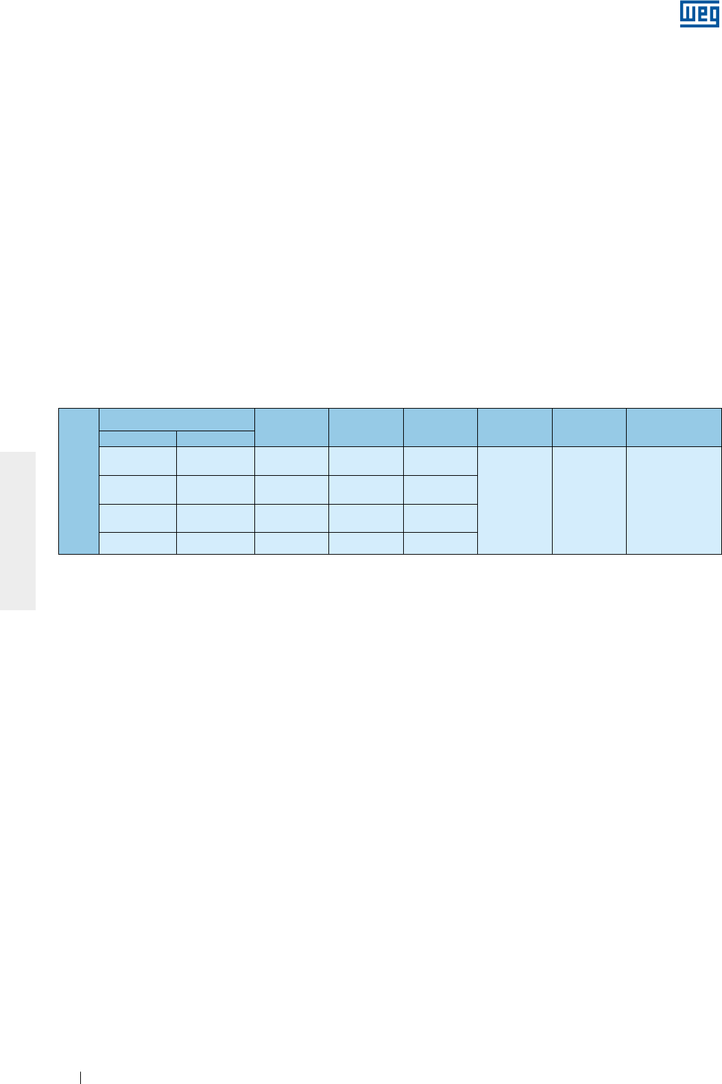
www.weg.net
Motores Eléctricos158
ESPAÑOL
Tabla 8.5 - Características de lubricación para motores HGF vertical de alto empuje.
8.2.2. Cojinetes de rodamiento lubricados a aceite
En motores con rodamientos lubricados a aceite, el cambio de aceite debe ser hecho con el motor parado,
siguiendo los procedimientos abajo:
g
Abra la respiración de entrada de aceite;
g
Retire el tapón de salida de aceite;
g
Abra la válvula y drene todo el aceite;
gCierre la válvula;
g
Recoloque el tapón;
g
Abastezca con la cantidad y especificación de aceite indicadas en la placa de identificación;
g
verifique si el nivel del aceite está en la mitad del visor;
gcierre la respiración de la entrada de aceite;
g
asegúrese de que no hay pérdida y que todos los orificios roscados no utilizados estén cerrados.
El cambio de aceite de los cojinetes debe ser realizado en el intervalo indicado en la placa de identificación o
siempre que el lubrificante presente alteraciones en sus características (viscosidad, pH, etc.).
El nivel de aceite debe ser mantenido en la mitad del visor de aceite y acompañado diariamente.
El uso de lubricantes con otras viscosidades requiere contacto previo con WEG.
Obs.: los motores HGF verticales para alto empuje son suministrados con cojinetes delanteros lubricados a
grasa y con cojinetes traseros, a aceite. Los cojinetes delanteros deben seguir las recomendaciones del ítem
8.2.1. La Tabla 8.5 presenta la cantidad y especificación de aceite para esa configuración.
Montaje alto empuje
Carcasa Polos Rodamiento Aceite (L) Intervalo (h) Lubricante Especificación
lubricante
IEC NEMA
315L/A/B y
315C/D/E
5006/7/8T y
5009/10/11T 4 - 8 29320 20
8000
Renolin
DTA 40 /
SHC 629
Aceite mineral
ISO VG150 con
aditivos
antiespuma y
antioxidantes
355L/A/B y
355C/D/E
5807/8/9T y
5810/11/12T 4 - 8 29320 26
400L/A/B y
400C/D/E
6806/7/8T y
6809/10/11T 4 - 8 29320 37
450 7006/10 4 - 8 29320 45
8.2.3. Cojinetes de rodamiento con lubricación de tipo Oil Mist
Verifique el estado de los sellados y, siempre que fuera necesario algún cambio, use solamente piezas
originales. Realice la limpieza de los componentes antes del montaje (anillos de fijación, tapas, etc.).
Aplique sellajuntas resistente al aceite lubricante utilizado, entre los anillos de fijación y las tapas.
A conexión de los sistemas de entrada, salida y drenaje de aceite deben ser realizados conforme la
Figura 6.12.
8.2.4. Cojinetes de deslizamiento
Para los cojinetes de deslizamiento, el cambio de aceite debe ser hecho en los intervalos indicados en la Tabla
8.6 y debe ser realizado, adoptando los siguientes procedimientos:
gPara el cojinete trasero, retire la tapa de inspección de la deflectora;
gDrene el aceite a través del drenaje localizado en la parte inferior de la carcasa del cojinete (ver Figura 8.1);
gCierre la salida de aceite;
gRetire el tapón de la entrada de aceite;
g
Abastezca con el aceite especificado y con la cantidad indicada en la Tabla 8.6;
g
Verifique si el nivel del aceite está en la mitad del visor;
g
Cierre la entrada de aceite;
g
Asegúrese de que no existe pérdida.
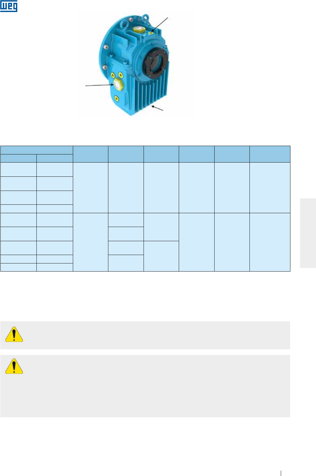
www.weg.net
Motores Eléctricos 159
ESPAÑOL
Entrada de aceite
Salida de aceite
Visor del nivel de aceite
Figura 8.1 - Cojinete de deslizamiento.
Tabla 8.6 - Características de lubricación para cojinetes de deslizamiento
Carcasa Polos Cojinete Aceite (L) Intervalo (h) Lubricante Especificación
lubrificante
IEC NEMA
315L/A/B y
315C/D/E
5006/7/8T y
5009/10/11T
2 9-80 2.8 8000 Renolin
DTA 10
Aceite mineral
ISO VG32 con
aditivos
antiespuma y
antioxidantes
355L/A/B y
355C/D/E
5807/8/9T y
5810/11/12T
400L/A/B y
400C/D/E
6806/7/8 y
6809/10/11T
450 7006/10
315L/A/B y
315C/D/E
5006/7/8T y
5009/10/11T
4 - 8
9-90
2.8
8000 Renolin DTA
15
Aceite mineral
ISO VG46 con
aditivos
antiespuma y
antioxidantes
355L/A/B y
355C/D/E
5807/8/9T y
5810/11/12T 9-100
400L/A/B y
400C/D/E
6806/7/8 y
6809/10/11T 11-110
4.7
450 7006/10 11-125
500 8006/10
El cambio de aceite de los cojinetes debe ser realizado en el intervalo indicado en la placa de identificación o
siempre que el lubricante presente alteraciones en sus características (viscosidad, pH, etc.).
El nivel de aceite debe ser mantenido en la mitad del visor y seguido diariamente.
No podrán ser usados lubrificantes con otras viscosidades sin antes consultar a WEG.
8.3. DESMONTAJE Y MONTAJE
Los servicios de reparación en motores deben ser efectuados solamente por personal capacitado
siguiendo las normas vigentes del país. Sólo deben ser utilizadas herramientas y métodos
adecuados.
Cualquier servicio de desmontaje y montaje debe ser realizado con el motor totalmente
desenergizado y completamente parado.
El motor apagado también puede presentar energía eléctrica en el interior de la caja de conexión:, en las
resistencias de calentamiento, en el devanado y en los capacitores.
Los motores accionados por convertidor de frecuencia pueden estar energizados incluso con el motor
parado.
Antes de iniciar el procedimiento de desmontaje, registre las condiciones actuales de la instalación, tales como
conexiones de los terminales de alimentación del motor y alineamiento / nivelación, los que deben ser
considerados durante el montaje posterior.
Realice el desmontaje de manera cuidadosa, sin causar impactos contra las superficies mecanizadas y / o en
las roscas.
www.weg.net
Motores Eléctricos160
ESPAÑOL
Monte el motor en una superficie plana para garantizar una buena base de apoyo. Los motores sin patas
deben ser calzados/trabados para evitar accidentes.
Deben ser tomados cuidados adicionales para no dañar las partes aisladas que operan bajo tensión eléctrica,
como por ejemplo, devanados, cojinetes aislados, cables de alimentación, etc..
Los elementos de sellado, como por ejemplo, juntas y sellados de los cojinetes deben ser cambiados siempre
que presenten desgaste o estén damnificados.
Los motores con grado de protección superior a IP55 son suministrados con producto sellante Loctite 5923
(Henkel) en las juntas y tornillos. Antes de montar los componentes, limpie las superficies y aplique una nueva
camada de este producto.
8.3.1. Caja de conexión
Al retirar la tapa de la caja de conexión para la conexión/desconexión de los cables de alimentación y
accesorios, deben ser adoptados los siguientes cuidados:
g
Asegúrese que durante la remoción de los tornillos, la tapa de la caja no dañe los componentes instalados en
su interior;
g
En caso que la caja de conexión sea suministrada con ojal de suspensión, éste debe ser utilizado para mover
la tapa de la caja de conexión;
g
Para motores suministrados con placa de bornes, deben ser asegurados los torques de apriete especificados
en la Tabla 8.7;
g
Verifique que los cables no entren en contacto con superficies con esquinas vivas.
g
Adopte los debidos cuidados para garantizar que el grado de protección inicial, indicado en la placa de
identificación del motor no sea alterado. Las entradas de cables para la alimentación y control deben utilizar
siempre componentes (como, por ejemplo, prensacables y electroductos) que atiendan las normas y
reglamentaciones vigentes de cada país;
g Asegúrese que la ventana de alivio de presión, cuando exista, no esté dañada. Las juntas de sellado de la
caja de conexión deben estar en perfecto estado para reutilización y deben ser posicionadas correctamente
para garantizar el grado de protección;
gVerifique los torques de apriete de los tornillos de fijación de la tapa de la caja conforme Tabla 8.7.
Tabla 8.7 - Torques de apriete para elementos de fijación [Nm]
Tipo de tornillo y junta M4 M5 M6 M8 M10 M12 M16 M20
Tornillo sextavado externo/interno
(s/ junta) 4 hasta 7 7 hasta
12
16 hasta
30
30 hasta
50
55 hasta
85
120 hasta
180
230
hasta
360
Tornillo ranura combinada (s/ junta) 3 hasta 5 5 hasta
10
10 hasta
18 - - - -
Tornillo sextavado externo/interno
(c/ junta con batiente metálica/cordón) - - 13 hasta
20
25 hasta
37
40 hasta
55
50 hasta
65 -
Tornillo ranura combinada (c/ junta
plana y/o batiente metálica/cordón) 3 hasta 5 4 hasta 8 8 hasta
15 - - - -
Tornillo sextavado externo/interno
(c/ junta plana) - - 8 hasta
15
18 hasta
30
25 hasta
40
35 hasta
50 -
Placa de bornes 1,5 hasta
4
3 hasta
6,5 6 hasta 9 10 hasta
18
15,5
hasta 30
30 hasta
50 -
Puesta a tierra 3 hasta 5 5 hasta
10
10 hasta
18
30 hasta
50
55 hasta
85
120 hasta
180 -
8.4. PROCEDIMIENTO PARA ADECUACION DE LA RESISTENCIA DE AISLAMIENTO
El motor debe ser desmontado y sus tapas, rotor completo (con eje), ventilador, deflectora y caja de conexión
deben ser separados, de modo que apenas la carcasa con el estator pase por un proceso de secado en una
horno apropiado, por un período de dos horas, a una temperatura no superior a 120 ºC. Para motores
mayores, puede ser necesario aumentar el tiempo de secado. Luego de ese período de secado, deje el estator
enfriar hasta que llegue a temperatura ambiente y repita la medición de la resistencia de aislamiento, conforme
ítem 5.4. En caso necesario, se debe repetir el proceso de secado del estator.
Si, luego de repetidos los procesos de secado del estator, la resistencia de aislamiento no vuelve a los niveles
aceptables, se recomienda hacer un análisis exhaustivo de las causas que llevaron a la caída del aislamiento
del devanado y, eventualmente podrá culminar con el rebobinado del motor.
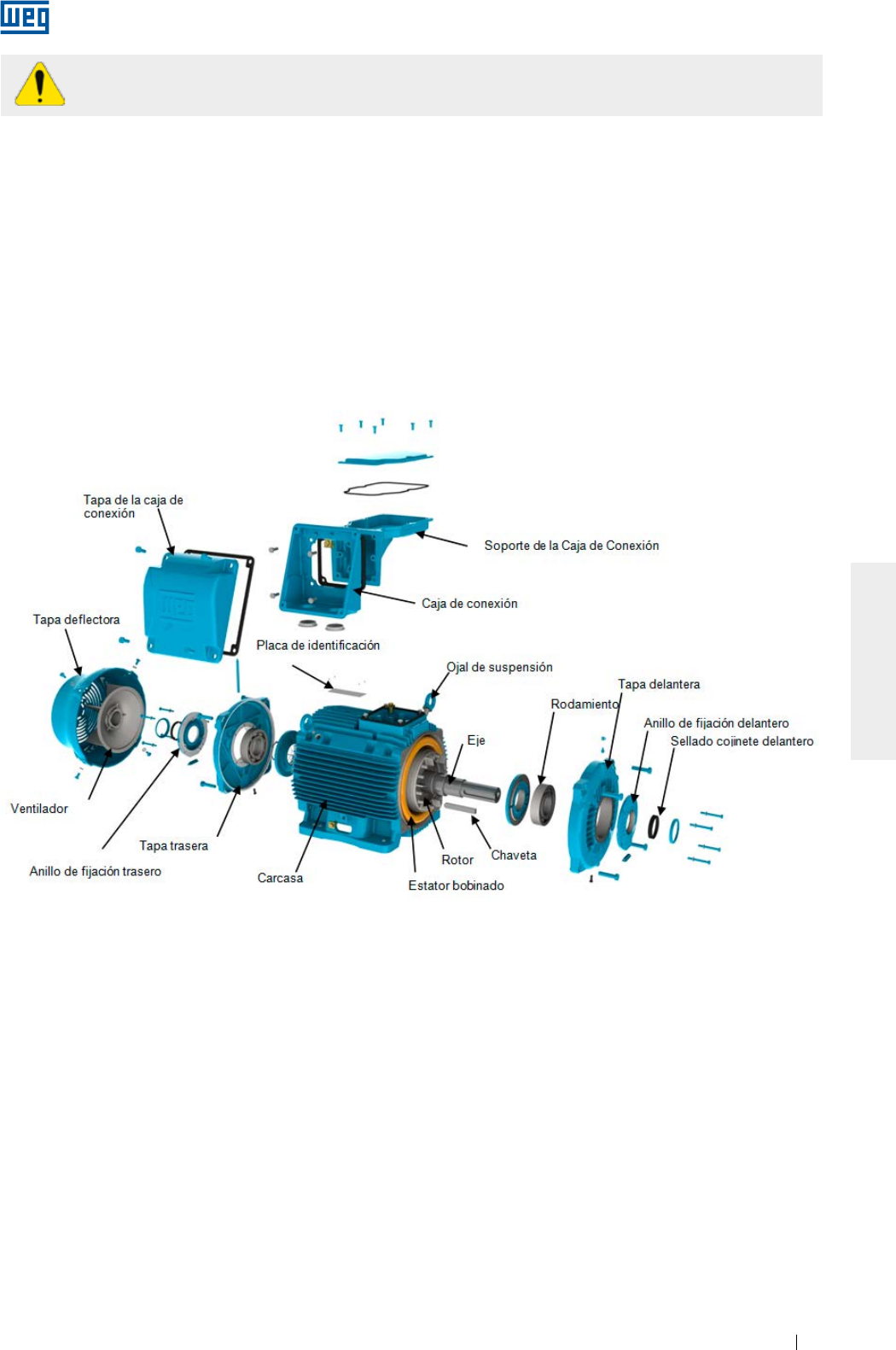
www.weg.net
Motores Eléctricos 161
ESPAÑOL
Para evitar el riesgo de shock eléctrico, descargue los terminales inmediatamente antes y después
de cada medición. En caso que el motor posea condensadores, éstos deben ser descargados.
8.5. PARTES Y PIEZAS
Al solicitar piezas para reposición, informe la designación completa del motor, así como su código y número de
serie, que pueden ser encontrados en la placa de identificación del motor.
Las partes y piezas deben ser adquiridas de la red de Asistencia Técnica Autorizada WEG. El uso de piezas no
originales puede resultar en la caída de desempeño y causar falla en el motor.
Las piezas sobresalientes deben ser almacenadas en local seco con una humedad relativa del aire de hasta
60%, con temperatura ambiente mayor a 5 °C y menor a 40 °C, libre de polvo, vibraciones, gases, agentes
corrosivos, sin variaciones bruscas de temperatura, en su posición normal y sin apoyar otros objetos sobre las
mismas.
Figura 8.2 - Vista explotada de los componentes de un motor W22
www.weg.net
Motores Eléctricos162
ESPAÑOL
9. INFORMACIONES AMBIENTALES
9.1. EMBALAGEM
Los motores eléctricos son suministrados en embalajes de cartón, plástico o madera. Estos materiales son
reciclables o reutilizables y deben recibir el destino correcto, conforme las normas vigentes de cada país. Toda
la madera utilizada en los embalajes de los motores WEG proviene de reforestación y no es sometida a ningún
tratamiento químico para su conservación.
9.2. PRODUCTO
Los motores eléctricos, bajo el aspecto constructivo, son fabricados esencialmente con metales ferrosos
(acero, hierro fundido), metales no ferrosos (cobre, aluminio) y plástico.
El motor eléctrico, de manera general, es un producto que posee una vida útil larga, no obstante en cuanto a
su descarte, WEG recomienda que los materiales del embalaje y del producto sean debidamente separados y
enviados a reciclaje.
Los materiales no reciclables deben, como determina la legislación ambiental, ser dispuestos de forma
adecuada, o sea, en aterramientos industriales, coprocesados en hornos de cemento o incinerados. Los
prestadores de servicios de reciclaje, disposición en aterramiento industrial, coprocesamiento o incineración de
residuos deben estar debidamente licenciados por el órgano ambiental de cada estado para realizar estas
actividades.
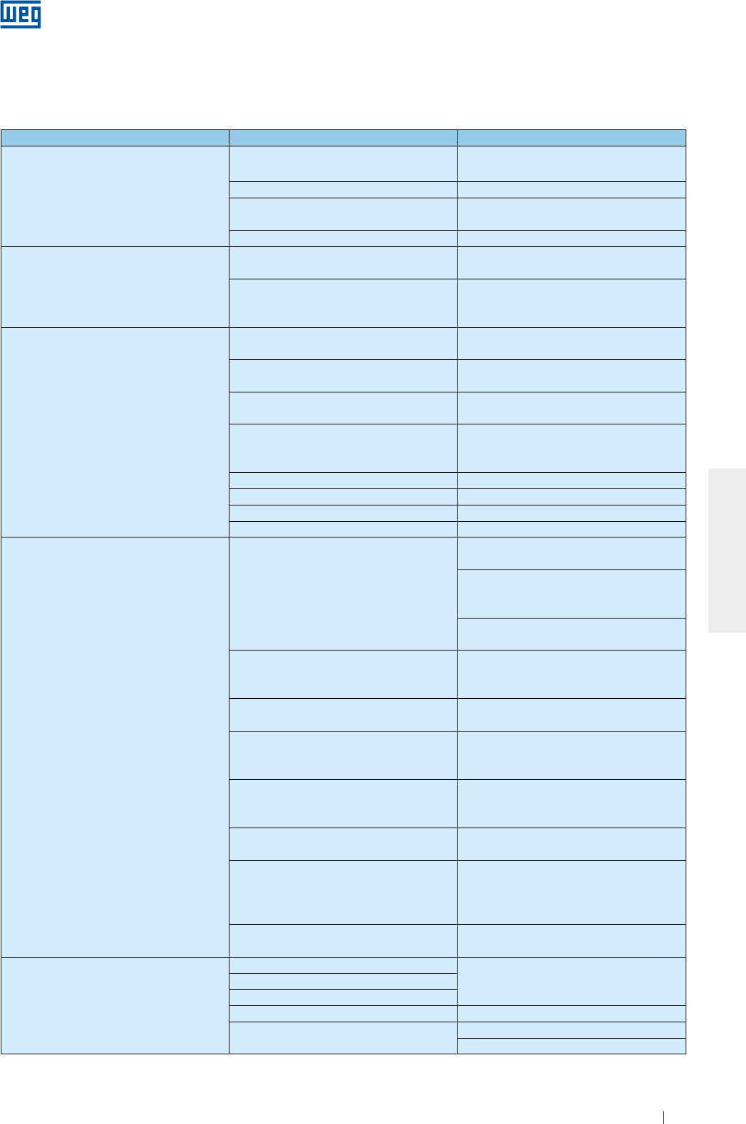
www.weg.net
Motores Eléctricos 163
ESPAÑOL
10. PROBLEMAS Y SOLUCIONES
Las instrucciones a seguir presentan una relación de problemas comunes con posibles soluciones. En caso de
duda, contacte al Asistente Técnico Autorizado, o a WEG.
Problema Posibles Causas Solución
El motor no parte, ni acoplado ni
desacoplado
Interrupción en la alimentación del motor Verifique el circuito de comando y los
cables de alimentación del motor
Fusibles quemados Substituya los fusibles
Error en la conexión del motor Corrija las conexiones del motor conforme
el diagrama de conexión
Cojinete trabado Verifique si el cojinete gira libremente.
Cuando acoplado con carga, el motor no
parte o parte muy lentamente y no alcanza
la rotación nominal
Carga con torque muy elevado durante la
partida
No aplique carga en la máquina accionada
durante la partida
Caída de tensión muy alta en los cables de
alimentación
Verifique el dimensionamiento de la
instalación (transformador, sección de los
cables, relés, disyuntores, etc.)
Ruido elevado/anormal
Defecto en los componentes de transmisión
o en la máquina accionada
Verifique la transmisión de fuerza, el
acoplamiento y el alineamiento
Base desalineada/desnivelada Realinee/nivele el motor y la máquina
accionada
Desbalance de los componentes o de la
máquina accionada Rehaga el balanceo
Tipos diferentes de balanceo entre motor y
acoplamiento (media chaveta, chaveta
entera)
Rehaga el balanceo
Sentido de rotación del motor incorrecto Invierta el sentido de rotación del motor
Tornillos de fijación sueltos Reapriete los tornillos
Resonancia de los cimientos Verifique el proyecto de los cimientos
Rodamientos damnificados Substituya el rodamiento
Calentamiento excesivo en el motor
Refrigeración insuficiente
Limpie las entradas y salidas de aire de la
deflectora, y de la carcasa
Verifique las distancias mínimas entre la
entrada de la deflectora de aire y las
paredes cercanas. Ver ítem 7
Verifique la temperatura del aire en la
entrada
Sobrecarga
Mida la corriente del motor, analizando su
aplicación y, si fuera necesario, disminuya la
carga
Excesivo número de partidas o momento
de inercia de la carga muy elevado Reduzca el número de partidas
Tensión muy alta
Verifique la tensión de alimentación del
motor. No sobrepase la tolerancia conforme
ítem 7.2
Tensión muy baja
Verifique la tensión de alimentación y la
caída de tensión en el motor. No sobrepase
la tolerancia conforme ítem 7.2
Interrupción de un cable de alimentación Verifique la conexión de todos los cables de
alimentación
Desequilibrio de tensión en los terminales
de alimentación del motor
Verifique si hay fusibles quemados,
comandos incorrectos, desequilibrio en las
tensiones de la red de alimentación, falta de
fase o en los cables de conexión
Sentido de rotación no compatible con el
ventilador unidireccional
Verifique el sentido de rotación conforme la
marcación del motor
Calentamiento del cojinete
Grasa aceite en demasía Realice la limpieza del cojinete y lubríquelo
según las recomendaciones
Envejecimiento de la grasa/aceite
Utilización de grasa/aceite no especificados
Falta de grasa/aceite Lubrique según las recomendaciones
Excesivo esfuerzo axial o radial Reduzca la tensión en las correas
Redimensione la carga aplicada al motor

www.weg.net
Motores Eléctricos164
ESPAÑOL
11. TERMINO DE GARANTIA
WEG Equipamentos Elétricos S/A, Unidad Motores (“WEG”), ofrece garantía contra defectos de fabricación o
de materiales para sus productos por un período de 18 meses, contados a partir de la fecha de emisión de la
factura de fábrica, o del distribuidor/revendedor, limitado a 24 meses de la fecha de fabricación.
Para motores de la línea HGF, la garantía ofrecida es de 12 meses, contados a partir de la fecha de emisión de
la factura de fábrica, o del distribuidor/revendedor, limitado a 18 meses a partir de la fecha de fabricación.
El párrafo anterior cuenta con los plazos de garantía legal, no siendo acumulativos entre sí.
En caso de que un plazo de garantía diferenciado esté definido en la propuesta técnica comercial para un
determinado suministro, éste prevalecerá por sobre los plazos definidos anteriormente.
Los plazos establecidos anteriormente no dependen de la fecha de instalación del producto ni de su puesta en
operación.
Ante un desvío en relación a la operación normal del producto, el cliente debe comunicar inmediatamente por
escrito a WEG sobre los defectos ocurridos, y poner a disposición el producto para WEG o su Asistente
Técnico Autorizado por el plazo necesario para la identificación de la causa del desvío, verificación de la
cobertura de garantía, y para su debida reparación.
Para tener derecho a la garantía, el cliente debe cumplir las especificaciones de los documentos técnicos de
WEG, especialmente aquellas previstas en el Manual de Instalación, Operación y Mantenimiento de los
productos, y las normas y regulaciones vigentes en cada país.
No poseen cobertura de garantía los defectos derivados de utilización, operación y/o instalación inadecuadas
o inapropiadas de los equipos, su falta de mantenimiento preventivo, así como defectos derivados de factores
externos o equipos y componentes no suministrados por WEG.
La garantía no se aplica si el cliente, por iniciativa propia, efectúa reparaciones y/o modificaciones en el equipo
sin previo consentimiento por escrito de WEG.
La garantía no cubre equipos, partes y/o componentes, cuya vida útil sea inferior al período de garantía. No
cubre, igualmente, defectos y/o problemas derivados de fuerza mayor u otras causas que no puedan ser
atribuidas a WEG, como por ejemplo, pero no limitado a: especificaciones o datos incorrectos o incompletos
por parte del cliente, transporte, almacenado, manipulación, instalación, operación y mantenimiento en
desacuerdo con las instrucciones suministradas, accidentes, deficiencias de obras civiles, utilización en
aplicaciones y/o ambientes para los cuales el producto no fue proyectado, equipos y/o componentes no
incluidos en el alcance de suministro de WEG. La garantía no incluye los servicios de desmantelamiento en las
instalaciones del cliente, los costos de transporte del producto, los costos de locomoción, hospedaje y
alimentación del personal de Asistencia Técnica, cuando sean solicitados por el cliente.
Los servicios en garantía serán prestados exclusivamente en talleres de Asistencia Técnica autorizadas por
WEG o en su propia fábrica. Bajo ninguna hipótesis, estos servicios en garantía prorrogarán los plazos de
garantía del equipo.
La responsabilidad civil de WEG está limitada al producto suministrado, no responsabilizándose por daños
indirectos o emergentes, tales como lucros cesantes, pérdidas de ingresos y similares que deriven del
contrato firmado entre las partes.

www.weg.net
Motores Eléctricos 165
ESPAÑOL
12. DECLARACION CE DE CONFORMIDAD
WEG Equipamentos Elétricos S/A
Av. Prefeito Waldemar Grubba, 3000
89256-900 - Jaraguá do Sul – SC – Brazil,
y su representante autorizado establecido en la Comunidad Europea,
WEGeuro – Industria Electrica SA
Persona de contacto: Luís Filipe Oliveira Silva Castro Araújo
Rua Eng Frederico Ulrich, Apartado 6074
4476-908 – Maia – Porto – Portugal
declaran por medio de esta, que los productos:
Motores de inducción WEG y componentes para uso en estos motores:
Trifásicos
Carcasas IEC 63 a 630
Carcasas NEMA 42, 48, 56 y 143 a 9610
...............
Monofásicos
Carcasas IEC 63 a 132
Carcasas NEMA 42, 48, 56 y 143 a 215
...............
cuando se instalen, mantengan y utilicen en las aplicaciones para los cuales fueron proyectados, y cuando se sigan las
debidas normas de instalación e instrucciones del proveedor, los mismos cumplen los requisitos de las siguientes Normas
Directivas Europeas:
Directivas:
Directiva de Baja Tensión 2006/95/CE*
Reglamento (CE) No 640/2009*
Directiva 2009/125/CE*
Directiva de Máquinas 2006/42/EC**
Directiva de Compatibilidad Electromagnética 2004/108/CE (los motores de inducción son considerados
intrínsecamente no perjudiciales en términos de compatibilidad electromagnética)
Normas:
EN 60034-1:2010/ EN 60034-2-1:2007/EN 60034-5:2001/A1:2007/ EN 60034-6:1993/ EN 60034-7:1993/A1:2001/
EN 60034-8:2007/ EN 60034-9:2005/A1:2007/ EN 60034-11:2004/ EN 60034-12:2002/A1:2007/ EN 60034-14:2004/
A1:2007/ EN 60034-30:2009, EN 60204-1:2006/AC:2010 y EN 60204-11:2000/AC:2010
Marcado CE: 1996
* Los motores eléctricos diseñados para su uso con una tensión superior a los 1.000 V se consideran fuera del alcance.
** Los motores eléctricos de baja tensión no están incluidos en el alcance, y los que estén diseñados para su uso con una
tensión superior a los 1.000 V, serán considerados cuasi máquina y serán suministrados con una
Declaración de Incorporación:
Los productos anteriores no pueden ser puestos en servicio mientras la máquina final donde se incorporen haya sido
declarada en conformidad con la Directiva de Máquinas.
Documentación técnica para los productos anteriores está recopilada de acuerdo con el apartado B anexo VII de la
Directiva de Máquinas 2006/42/CE.
Nosotros nos comprometemos a transmitir, en respuesta a un requerimiento debidamente motivado de las autoridades
nacionales, la información pertinente relativa a la cuasi máquina identificada anteriormente, vía los representantes
autorizados de WEG establecidos en la Comunidad Europea. El método de transmisión será electrónico o físico, y no
deberá perjudicar los derechos de propiedad intelectual del fabricante.
Milton Oscar Castella
Director de Ingeniería
Jaraguá do Sul, 08 de Abril 2013

www.weg.net
Motores Eléctricos166
ESPAÑOL
www.weg.net
Elektrische Motoren168
INSTALLATIONS-, BETRIEBS- UND WARTUNGSANLEITUNG
FÜR ELEKTRISCHE MOTOREN
Die hier enthaltenen Anweisungen sind für WEG-Drehstrom-Asynchronmaschinen mit
Kurzschlussläufern, permanentmagneterregte Synchronmaschinen und Hybrid-
Synchronmaschinen (mit Kurzschlussläufern + Permanentmagneten) für Nieder- und
Hochspannung in den Baugrößen IEC 56 bis 630 und in den Baugrößen NEMA 42 bis 9606/10
gültig.
Für die unten aufgezeichneten Baureihen müssen, außer den hier enthaltenen Informationen,
hauptsächlich ihre entsprechenden Betriebsanleitungen und deren Normen berücksichtigt
werden:
g Brandgaslüftermotoren (Smoke Extraction Motor);
g Motoren mit elektromagnetischer Bremse;
g Motoren für explosionsgefährdete Bereiche;
Diese Maschinen erfüllen folgende Normen, wenn anwendbar:
g IEC 60034-1: Rotating Electrical Machines - Part 1: Rating and Performance.
g NEMA MG 1: Motors and Generators.
g CSA C 22.2 N°100: Motors and Generators.
g UL 1004-1: Rotating Electrical Machines - General Requirements.
g NBR 17094-1: Máquinas Elétricas Girantes - Motores de Indução - Parte 1: trifásicos.
g NBR 17094-2: Máquinas Elétricas Girantes - Motores de Indução - Parte 2: monofásicos.
Falls bei dem Lesen dieser Betriebsanleitung Fragen auftreten sollten, bitten wir Sie die Firma
WEG anzusprechen. Weitere Information können Sie auch auf der Website www.weg.net
finden.

www.weg.net
Elektrische Motoren 169
DEUTSCH
INHALTSVERZEICHNIS
1. BEGRIFFSERKLÄRUNG 171
2. ALLGEMEIN 172
2.1. WARNSYMBOL ....................................................................................................................................172
2.2. EINGANGSPRÜFUNGEN ...................................................................................................................172
2.3. LEISTUNGSSCHILDER ......................................................................................................................173
3. SICHERHEITSHINWEISE 176
4. HANDHABUNG UND TRANSPORT 177
4.1. HANDHABUNG ...................................................................................................................................177
4.1.1. Handhabung von horizontal aufgestellten Motoren mit einer Transportöse ......................178
4.1.2. Handhabung von horizontal aufgestellten Motoren mit zwei Transportösen ....................178
4.1.3. Handhabung von vertikal aufgestellten Motoren ..................................................................179
4.1.3.1. Handhabung von vertikal aufgestellten Motoren der Baureihe W22 ............................... 180
4.1.3.2. Handhabung von vertikal aufgestellten Motoren der Baureihe HGF ...............................181
4.2. VERTIKAL AUFGESTELLTE MOTOREN DER REIHE W22 IN HORIZONTALLAGE WENDEN ....... 182
5. LAGERUNG 184
5.1. BEARBEITETE OBERFLÄCHEN ........................................................................................................ 184
5.2. STAPELN VON VERPACKUNGEN ................................................................................................... 184
5.3. LAGER ................................................................................................................................................. 185
5.3.1. Fettgeschmierte Wälzlager...................................................................................................... 185
5.3.2. Ölgeschmierte Wälzlager ....................................................................................................... 185
5.3.3. Schmierölnebel geschmierte Wälzlager................................................................................ 186
5.3.4. Gleitlager ................................................................................................................................... 186
5.4. ISOLATIONSWIDERSTAND ............................................................................................................... 186
5.4.1. Messung des Isolationswiderstandes .................................................................................. 186
6. INSTALLATION 189
6.1. FUNDAMENTE FÜR DEN MOTOR .................................................................................................... 190
6.2. MOTORAUFSTELLUNG ......................................................................................................................192
6.2.1. Fußbefestigte Motoren .............................................................................................................192
6.2.2. Flanschbefestigte Motoren .................................................................................................... 193
6.2.3. B30 Pad-mounted Motoren ..................................................................................................... 193
6.3. AUSWUCHTEN .................................................................................................................................. 194
6.4. ÜBERTRAGUNGSELEMENTE ........................................................................................................... 194
6.4.1. Direkte Kupplung ...................................................................................................................... 194
6.4.2. Kupplung über Getriebe ......................................................................................................... 194
6.4.3. Antrieb über Riemenscheiben und Riemen .......................................................................... 194
6.4.4. Kupplung von Motoren mit Gleitlagern ................................................................................. 194
6.5. NIVELLIEREN ................................................................................................................................... 195
6.6. AUSRICHTEN...................................................................................................................................... 195
6.7.
ANSCHLUSS VON ÖLGESCHMIERTEN ODER MIT SCHMIERÖLNEBEL GESCHMIERTEN LAGERN
.. 196
6.8. ANSCHLUSSSYSTEM VON MOTOREN MIT WASSERKÜHLERN ................................................. 196
6.9. ELEKTRISCHER ANSCHLUSS ........................................................................................................ 196
6.10. SCHALTUNG VON THERMISCHEN SCHUTZVORRICHTUNGEN ............................................... 199
6.11. WIDERSTANDSTHERMOMETER (PT-100) ..................................................................................... 200
6.12. ANSCHLUSS DER STILLSTANDSHEIZUNG .................................................................................. 202
6.13. ANLAUFMETHODEN ........................................................................................................................ 202

www.weg.net
Elektrische Motoren170
DEUTSCH
6.14. MOTOREN ÜBER FREQUENZUMRICHTER BETRIEBEN ............................................................ 203
6.14.1. Einsatz von Filtern (dU/dt) ...................................................................................................... 203
6.14.1.1. Motorwicklungen mit emailliertem Runddraht ................................................................. 203
6.14.1.2. Motorwicklungen mit vorgeformten Flachdrahtspulen .................................................. 204
6.14.2. Lagerisolierung ....................................................................................................................... 204
6.14.3. Schaltfrequenz ........................................................................................................................ 204
6.14.4. Beschränkungen der mechanischen Drehzahl ................................................................... 205
7. INBETRIEBNAHME 206
7.1. ERSTSTART ......................................................................................................................................... 206
7.2. BETRIEB .............................................................................................................................................. 208
7.2.1. Schwingungsgrenzen ............................................................................................................... 209
8. WARTUNG 210
8.1. ALLGEMEINE ÜBERPRÜFUNGEN ....................................................................................................210
8.2. LAGERSCHMIERUNG ........................................................................................................................210
8.2.1. Fettgeschmierte Wälzlager ......................................................................................................211
8.2.1.1. Lager ohne Nachschmiereinrichtung ..................................................................................213
8.2.1.2. Lager mit Nachschmiereinrichtung ....................................................................................213
8.2.1.3. Verträglichkeit des Fettes Mobil Polyrex EM mit anderen Fetten ....................................213
8.2.2. Ölgeschmierte Wälzlager .........................................................................................................214
8.2.3. Schmierölnebel geschmierte Wälzlager ...............................................................................214
8.2.4. Gleitlager ....................................................................................................................................214
8.3. DEMONTAGE UND MONTAGE ..........................................................................................................215
8.3.1. Klemmenkasten .........................................................................................................................216
8.4. MINDESTISOLATIONSWIDERSTAND UND EVTL. TROCKNUNG DER WICKLUNG ...................216
8.5. ERSATZTEILE .....................................................................................................................................217
9. INFORMATION ÜBER DEN UMWELTSCHUTZ 218
9.1. VERPACKUNGEN ...............................................................................................................................218
9.2. PRODUKT ............................................................................................................................................218
10. STÖRUNGSSUCHE UND BEHEBUNG 219
11. GEWÄHRLEISTUNG 220
12. CE-KONFORMITÄTSERKLÄRUNG 221

www.weg.net
Elektrische Motoren 171
DEUTSCH
1. BEGRIFFSERKLÄRUNG
Auswuchten: auswuchten ist ein Arbeitsverfahren, durch den die Massenverteilung eines Läufers geprüft und
wenn nötig korrigiert wird, um sicherzustellen, dass eine Restunwucht oder die elektrisch magnetischen
Schwingungen an den Lagerzapfen bzw. dass die Lagerkräfte bei Betriebsdrehzahl in international festgelegten
Grenzen liegen [ISO 1925:2001, Definition 4.1].
Auswuchtgütestufe: gibt die Maximalamplitude der Schwinggeschwindigkeit [mm/s] eines frei im Raum
drehenden Läufers wieder und ist das Produkt einer bestimmten Unwucht und der Winkelgeschwindigkeit des
Läufers bei maximaler Drehzahl.
Geerdetes Teil: spannungsführende Bauteile, die elektrisch mit einem Erdungssystem in Verbindung stehen.
Aktivteile: sind Leiter oder Teile einer elektrischen Ausrüstung, die im Normalbetrieb Strom führen,
einschließlich des Neutralleiters.
Beauftragtes Personal: sind Mitarbeiter, die vom Unternehmen für die Ausführung dieser Arbeit beauftragt
worden sind.
Qualifiziertes Personal: sind Personen, die auf Grund Ihrer Ausbildung, Erfahrung und Unterweisung,
ausreichende Kenntnisse über die einschlägigen Normen und der Unfallverhütungsvorschriften haben. Nur
dann sind sie berechtigt, nach Beauftragung des Verantwortlichen für die Sicherheit, unter Beachtung der
Betriebsverhältnisse und der Anlage selbst, die erforderlichen Tätigkeiten auszuführen, um die Maschine zu
installieren, in Betrieb zu setzen und zu warten.
www.weg.net
Elektrische Motoren172
DEUTSCH
2. ALLGEMEIN
Elektromotoren haben bei Normalbetrieb gefährliche, spannungsführende und rotierende Teile
sowie möglicherweise heiße Oberflächen, die Personenschäden/Körperverletzungen verursachen
können. Deshalb sind alle Arbeiten zum Transport, Anschluss zur Inbetriebnahme und regelmäßige
Instandhaltung von qualifiziertem, verantwortlichem Fachpersonal auszuführen.
Die jeweils geltenden nationalen, örtlichen und anlagespezifischen Bestimmungen und die entsprechenden
Erfordernisse sind zu berücksichtigen.
Die Nichtbeachtung der Anweisungen in dieser Betriebsanleitung und auf der Internetseite kann zu
Personen- und Sachschäden führen und hebt die Produktgewährleistung auf.
Der Benutzer ist für die korrekte Bestimmung der Umgebungs- und Einsatzeigenschaften
verantwortlich.
Wartungs-, Inspektions- und Reparaturarbeiten am Motor während der Gewährleistungsfrist dürfen
nur von zugelassen WEG-Kundendienststellen vorgenommen werden um nicht die Gewährleistung
aufzuheben.
Die Betriebsanleitungen können aus Gründen der Übersichtlichkeit nicht alle Detailinformation zu möglichen
Bauvarianten enthalten und können nicht jeden denkbaren Fall der Aufstellung, des Betriebes oder der Wartung
berücksichtigen. Demgemäß enthalten die Betriebsanleitungen im Wesentlich nur solche Hinweise, die bei
bestimmungsgemäßer Verwendung für qualifiziertes Personal erforderlich sind. Die in dieser Betriebsanleitung
enthaltenen Bilder sind nur als Illustration anzusehen.
Für den Einsatz von Brandgaslüftermotoren ist zusätzlich die entsprechende Betriebsanleitung (Smoke
Extraction Motors) 50026367 (English) auf der Website www.weg.net zu berücksichtigen.
Für den Betrieb von Bremsmotoren, ist die entsprechende Betriebsanleitung für WEG-Bremsmotoren (Kode Nr.
50006742 - auf English) oder die Betriebsanleitung Intorq (Kode Nr. 50021973 - auf English) auf der Website
www.weg.net zu berücksichtigen.
Informationen über die zugelassene Radial- und Axialbelastung der Welle sind im technischen Katalog des
Produktes zu finden.
2.1. WARNSYMBOL
Warnung über Sicherheit und Gewährleistung.
2.2. EINGANGSPRÜFUNGEN
Die Motoren werden während des Herstellungsverfahrens geprüft.
Unmittelbar nach dem Empfang sind die Verpackung und der Motor auf äußerliche Transportschäden zu
untersuchen. Werden nach der Auslieferung Beschädigungen festgestellt, sind diese dem
Transportunternehmen, der Versicherungsgesellschaft und der Firma WEG sofort schriftlich zu melden. Die
versäumte Meldung der entdeckten Schäden hebt die Garantie auf.
Unmittelbar nach dem Empfang ist das Produkt einer kompletten Überprüfung zu unterziehen:
g Überprüfen, ob die auf dem Leistungsschild angegebenen Daten mit den Bestelldaten übereinstimmen;
g Transportsicherungen entfernen (wenn vorhanden). Die Motorwelle etwas von Hand drehen um zu
gewährleisten, dass sie sich frei drehen lässt;
g Sicherstellen, dass der Motor während des Transportes einer nicht zu hohen Luftfeuchtigkeit und größere
Mengen von Staub ausgesetzt war;
g Den Korrosionsschutz am Wellenende und die Verschlussstopfen vom Klemmenkasten nicht entfernen.
Diese Schutzvorrichtungen dürfen erst unmittelbar vor der Motoraufstellung entfernt werden.

www.weg.net
Elektrische Motoren 173
DEUTSCH
Bild 2.1 - Leistungsschilder von IEC-Motoren
2.3. LEISTUNGSSCHILDER
Die Leistungsschilder enthalten Informationen über die Bau- und Betriebseigenschaften des Motors. Bild 2.1
und Bild 2.2 geben Layout-Beispiele von Leistungsschildern wieder.
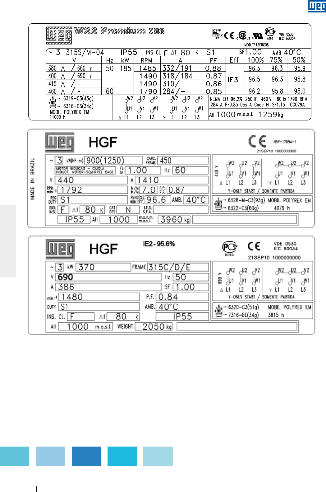
www.weg.net
Elektrische Motoren174
DEUTSCH
Bild 2.1 - Leistungsschilder von IEC-Motoren
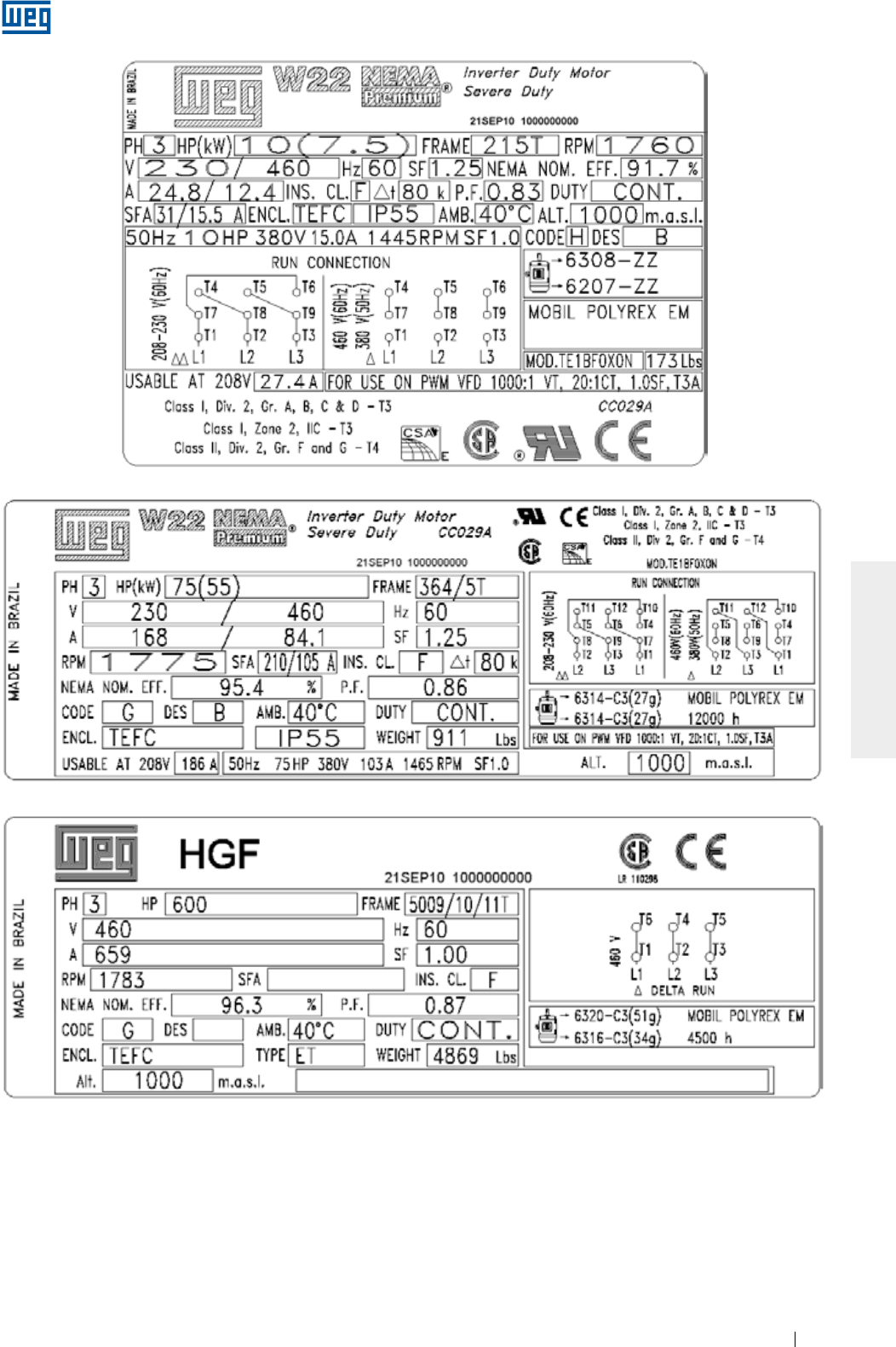
www.weg.net
Elektrische Motoren 175
DEUTSCH
Bild 2.2 - Leistungsschilder von NEMA-Motoren
www.weg.net
Elektrische Motoren176
DEUTSCH
Elektromotoren haben bei Normalbetrieb gefährliche, spannungsführende und rotierende Teile
sowie möglicherweise heiße Oberflächen, die Personenschäden/Körperverletzungen verursachen
können. Deshalb sind alle Arbeiten zum Transport, Lagerung, Anschluss, zur Inbetriebnahme und
zur regelmäßigen Instandhaltung nur von qualifiziertem und verantwortlichem Fachpersonal auszuführen.
3. SICHERHEITSHINWEISE
Wartungs- Inspektions- und Reparaturarbeiten dürfen nur nach Abschalten und Stillstand der
Maschine vorgenommen werden. Es müssen alle Vorsichtsmaßnahmen getroffen werden, um ein
unbeabsichtigtes Einschalten zu vermeiden.
Nur qualifiziertes Personal, die auf Grund Ihrer Ausbildung, Erfahrung und Unterweisung
ausreichende Kenntnisse über einschlägige Normen und Unfallverhütungsvorschriften haben, sind
berechtigt, unter Beachtung der entsprechenden Betriebsverhältnisse, die erforderlichen
Tätigkeiten wie Installation, Inbetriebnahme und Wartung an dieser Maschine unter Einsatz von geeigneten
Werkzeugen auszuführen. Dieses qualifizierte Personal muss auch ausreichende Kenntnisse hinsichtlich
des Einsatzes und Umganges mit persönlichen Schutzausrüstungen (PSA) zur Ausführung dieser Arbeiten
haben.
Für die Installation, Wartung und Überprüfungen müssen immer die einschlägigen Normen und
Sicherheitsvorschriften des betreffenden Landes befolgt werden.
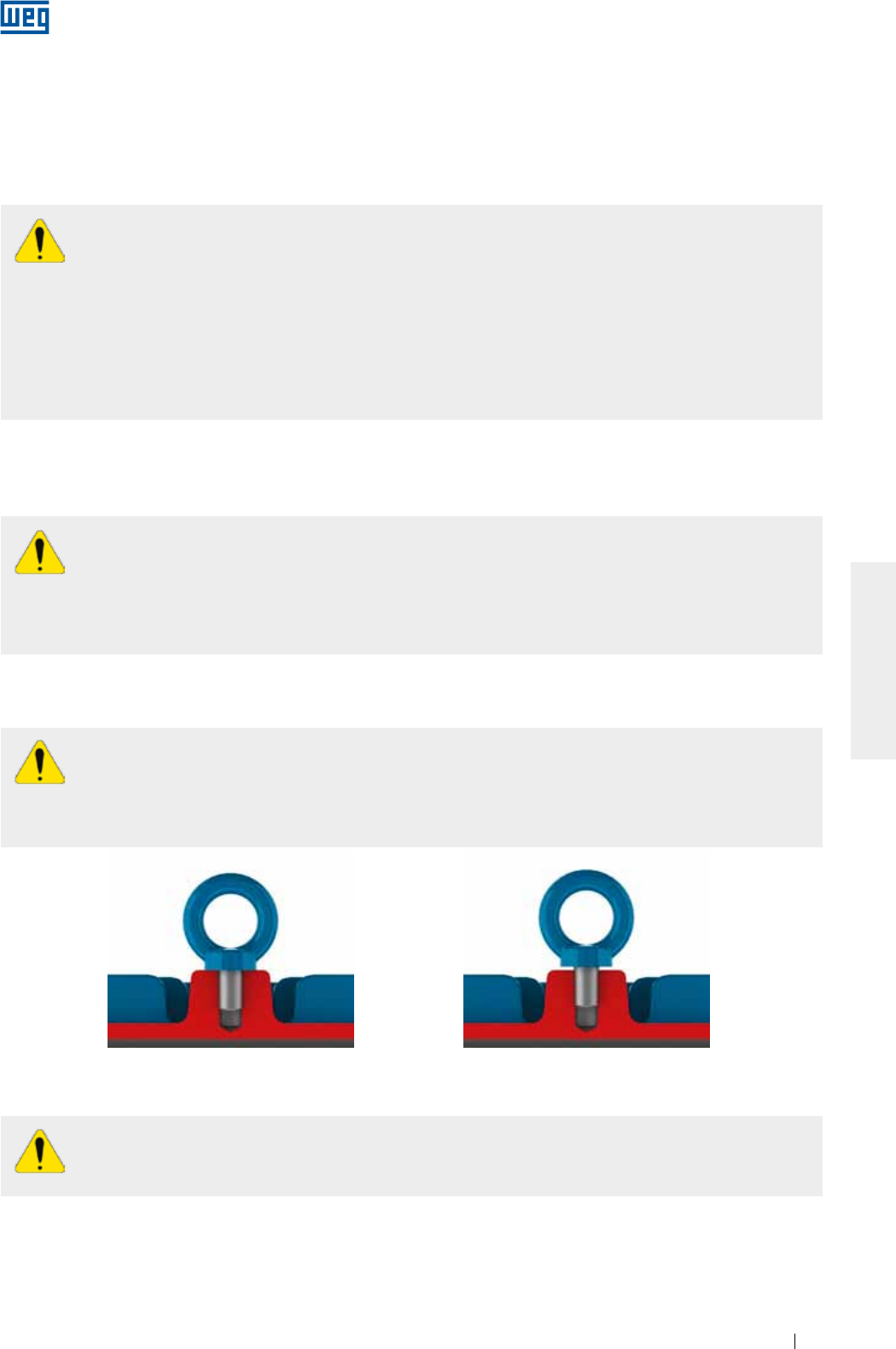
www.weg.net
Elektrische Motoren 177
DEUTSCH
Bild 4.2 - Falsche Befestigung der
Transportösen
Bild 4.1 - Richtige Befestigung der
Transportösen
4. HANDHABUNG UND TRANSPORT
Die Transportösen am Gehäuse dienen ausschließlich zum Heben des Motors. Sie dürfen nicht
zum Heben nach dem Zusammenbau von Motor + angetriebener Maschine, Motorbasis,
Riemenscheiben, Lüfter, Pumpe, Untersetzungsgetriebe, usw. verwendet werden.
Beschädigte Transportösen mit Rissen, verbogen, usw., müssen gegen Neue ausgetauscht werden.
Überprüfen Sie immer ihren Zustand, bevor sie zum Transport eingesetzt werden.
Die Transportösen an der Fremdbelüftung, Deckeln, Lagerschilden, Klemmenkästen, usw. dienen
ausschließlich zum Heben dieser Bauteile und dürfen niemals zum Heben der komplett
zusammengebauten Maschine eingesetzt werden.
Um Lagerschäden während des Transportes zu vermeiden, sind Motoren mit Zylinderrollenlagern
bzw. Schrägkugellagern immer mit einer Läuferfeststellvorrichtung zu transportieren. Für weitere
Transporte muss die Transportsicherung erneut verwendet werden, auch wenn dies die
Abkopplung der angetriebenen Maschine erfordert.
Alle Motoren der HGF-Reihe, unabhängig des eingesetzten Lagertyps, müssen zum Transport immer mit
einer Läuferfeststellvorrichtung versehen werden.
Vor jedem Transport ist sicherzustellen, dass die Transportösen komplett eingeschraubt sind und
mit ihrer gesamten Fläche plan aufliegen. Bild 4.1 und Bild 4.2 zeigen den richtigen Einbau der
Transportöse.
Beim Transport ist immer das angegebene Gewicht des Motors, die Tragfähigkeit der Seile, Gurte,
Transportösen und Hebevorrichtungen zu berücksichtigen.
Der Schwerpunkt eines Motors variiert in Bezug zur Leistung und des angebauten Zubehörs. Beim
Heben der Maschine immer den höchst zugelassenen Hebewinkel wie nachstehend gezeigt,
berücksichtigen.
Einzeln verpackte Motoren dürfen niemals an der Verpackung oder an der Welle gehoben werden, sondern
nur an den dafür vorgesehenen Transportösen (wenn vorhanden) eingehängt und mit geeigneten Hebezeugen
oder Gabelstaplern transportiert werden. Die Transportösen sind ausschließlich für das auf dem
Leistungsschild angegebene Gewicht des Motors ausgelegt. Motoren, die auf einer Palette geliefert werden,
dürfen nur an der entsprechenden Basis der Palette gehoben werden. Niemals die Verpackung kippen.
Um Lagerschäden zu vermeiden, muss der Motor immer sanft gehoben und abgesetzt werden. Die
Transportösen dürfen nicht zu hohen Belastung aussetzt werden, was einen Bruch derselben zur Folge haben
könnte.
4.1. HANDHABUNG
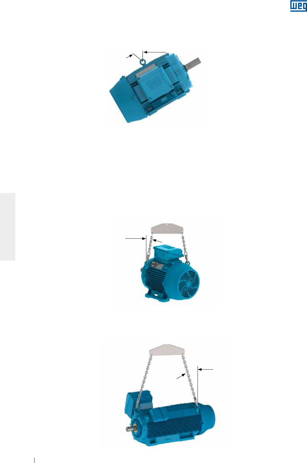
www.weg.net
Elektrische Motoren178
DEUTSCH
4.1.1. Handhabung von horizontal aufgestellten Motoren mit einer Transportöse
Für Motoren mit einer Transportöse sollte der Hebewinkel der Hebeketten oder Seile, nie mehr als 30º in Bezug
auf die Senkrechte betragen. Siehe Bild 4.3.
Bild 4.3 - Max. zugelassener Hebewinkel für Motoren mit einer Transportöse
4.1.2. Handhabung von horizontal aufgestellten Motoren mit zwei Transportösen
Sind die Motoren mit zwei oder mehreren Transportösen ausgestattet, müssen alle mitgelieferten
Transportösen gleichzeitig zum Heben eingesetzt werden.
Es gibt zwei Anordnungsmöglichkeiten für die Transportösen (vertikale und schräge), wie nachfolgend
veranschaulicht wird:
g Bei Motoren mit vertikalen Transportösen, wie in Bild 4 gezeigt, dürfen die Hebeketten oder Seile einen
Winkel von 45° in Bezug auf die Senkrechte nicht überschreiten. Hier wird der Einsatz eines Querbalkens zur
Einhaltung der vertikalen Anordnung der Hebeketten oder Seile zum Schutz der Motorbauteile empfohlen.
Bild 4.4 - Max. zugelassener Hebewinkel für Motoren mit zwei oder mehreren Transportösen
45° Máx.
Für Motoren der HGF-Reihe, siehe Bild 4.5, sollte der Hebewinkel der Hebeketten oder Seile nie mehr als 30º in
Bezug auf die Senkrechte betragen;
Bild 4.5 - Max. zugelassener Hebewinkel für horizontal aufgestellte Motoren der Baureihe HGF.
30° Máx.
30° Max.
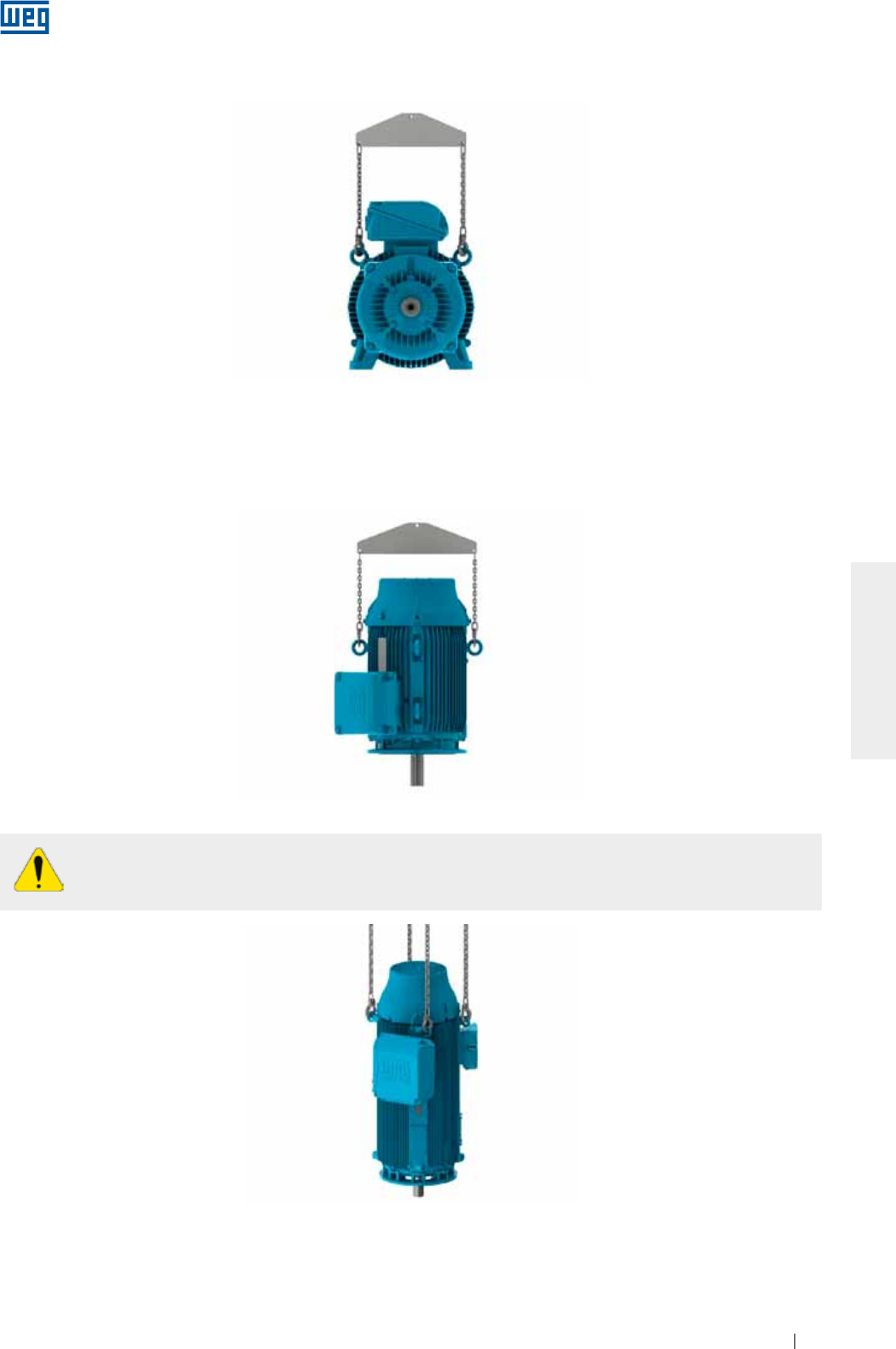
www.weg.net
Elektrische Motoren 179
DEUTSCH
g Bei Motoren mit schräg angebrachten Transportösen, wie in Bild 4.6 gezeigt, muss ein Querbalken zur
Einhaltung der vertikalen Anordnung der Hebeketten oder Seile und zum Schutz der Motorbauteile eingesetzt
werden.
Bild 4.6 - Einsatz eines Querbalkens zum Heben
4.1.3. Handhabung von vertikal aufgestellten Motoren
Zur Handhabung von vertikal aufgestellten Motoren, wie in Bild 4.7 gezeigt, muss ein Querbalken zur Einhaltung
der vertikalen Anordnung der Hebeketten oder Seile und zum Schutz der Motorbauteile eingesetzt werden.
Bild 4.7 - Handhabung von vertikal aufgestellten Motoren
Vertikal aufgestellte Motoren dürfen nur an den hierfür an der Nichtantriebsseite diametral
entgegengesetzter Transportösen gehoben werden. Siehe Bild 4.8.
Bild 4.8 - Heben von Motoren der Baureihe HGF

www.weg.net
Elektrische Motoren180
DEUTSCH
4.1.3.1. Handhabung von vertikal aufgestellten Motoren der Baureihe W22
Aus Sicherheitsgründen während des Transportes werden vertikal aufgestellte Motoren meistens in horizontaler
Position verpackt und geliefert.
Zur Positionierung der Motoren der Baureihe W22 mit schräg angebrachten Transportösen (siehe Bild 4.6) in
die vertikale Position, muss wie folgt vorgegangen werden:
1. Sicherstellen, dass die Transportösen richtig befestig sind. Siehe Bild 4.1;
2. Den Motor auspacken und die oben liegenden angebrachten Transportösen verwenden. Siehe Bild 4.9;
Bild 4.9 - Den Motor auspacken
3. Das andere Paar Transportösen einbauen. Siehe Bild 4.10;
Bild 4.10 - Einbau des zweiten Paares von Transportösen
4. Die Last auf dem ersten Paar Transportösen reduzieren und mit einer 2. Hebevorrichtung die Drehung der
Motors, wie in Bild 4.11 gezeigt, vornehmen. Dieses Verfahren sollte langsam und vorsichtig ausgeführt
werden.
Bild 4.11 - Endergebnis: Positionierung von vertikal aufgestellte Motoren
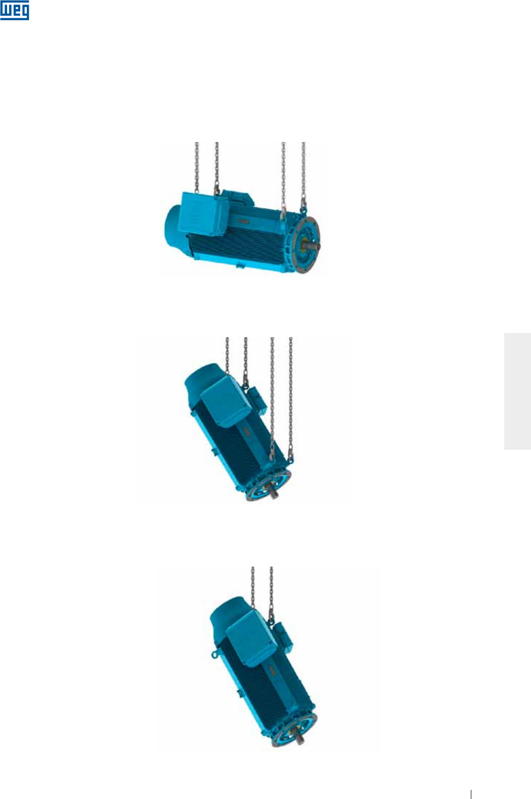
www.weg.net
Elektrische Motoren 181
DEUTSCH
4.1.3.2. Handhabung von vertikal aufgestellten Motoren der Baureihe HGF
Vertikal aufgestellte Motoren der Baureihe HGF werden mit vier Transportösen, zwei an der Antriebsseite und
zwei an der Nichtantriebsseite geliefert. Die Motoren dieser Baureihe werden normalerweise in der
Horizontallage transportiert und müssen zur Installation in die vertikale Position gedreht werden.
Um die Motoren der Baureihe HGF in die vertikale Lage aufzustellen, muss wie folgt vorgegangen werden:
1. Den Motor an den vier seitlich angebrachten Transportösen mit zwei Hebevorrichtungen heben. Siehe
Bild 4.12;
Bild 4.12 - Den Motor der Baureihe HGF an den vier seitlich angebrachten Transportösen mit zwei Hebevorrichtungen heben
2. Die Antriebsseite ablegen, während die Nichtantriebsseite gehoben wird, bis ein Gleichgewicht erreicht wird.
Siehe Bild 4.13;
Bild 4.13 - Motoren der Baureihe HGF in die vertikale Lage aufstellen
3. Die Hebeseile/Hebeketten an der Antriebsseite aushängen um den Motor um 180º drehen zu können.
Die ausgehängten Hebeseile/Hebeketten nun in die zwei übrigen Transportösen der Nichtantriebsseite
einhängen. Siehe Bild 4.14
Bild 4.14 - Den Motor der Baureihe HGF mit Hebeseilen/Hebeketten an der Nichtantriebsseite eingehängt, heben
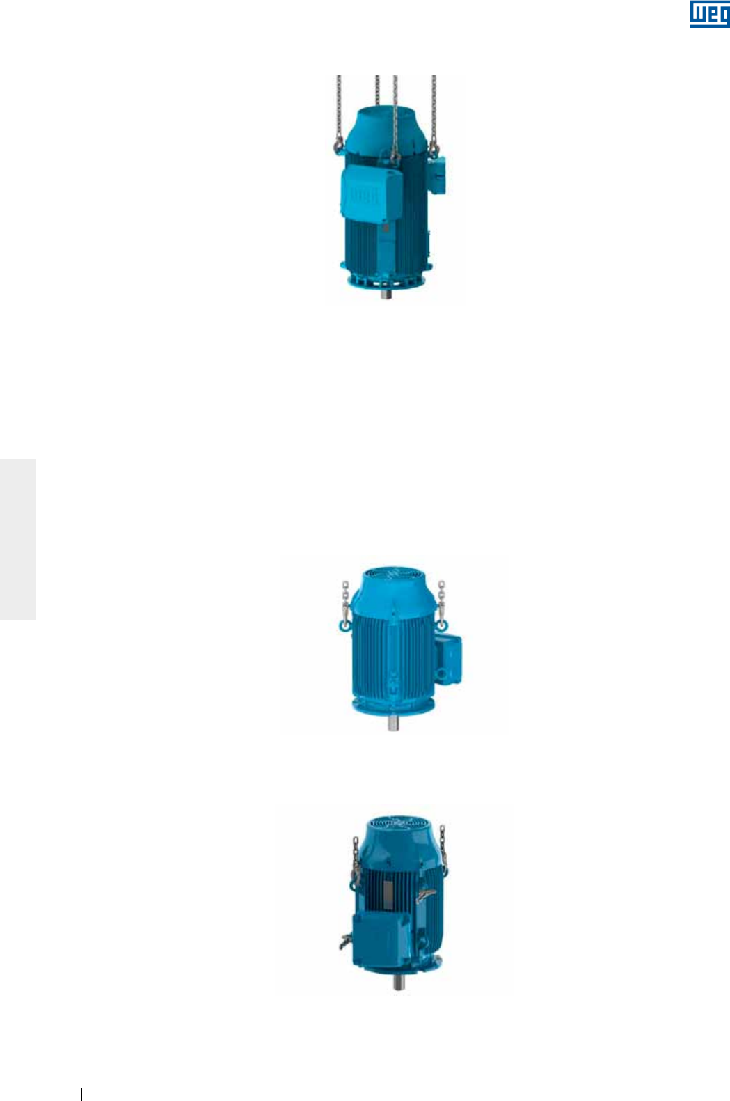
www.weg.net
Elektrische Motoren182
DEUTSCH
4. Die freien Seile/Ketten nun in die zwei übrigen Transportösen an der Nichtantriebsseite einhängen, den Mo-
tor anheben bis ein Gleichgewicht in der vertikalen Lage erreicht ist. Sie Bild 4.15.
Bild 4.15 - Motor der Baureihe HGF Motor in der vertikalen Lage
Dieses Verfahren gilt für die Handhabung von Motoren, die in horizontaler Lage transportiert, aber in vertikaler
Lage eingebaut werden. Diese Vorgehensweise gilt auch in umgekehrter Weise für Motoren, die in vertikaler
Lage transportiert, aber in die horizontale Lage eingebaut werden sollen.
4.2. VERTIKAL AUFGESTELLTE MOTOREN DER REIHE W22 IN HORIZONTALLAGE WENDEN
Um vertikal aufgestellte Motoren der Reihe W22 in die horizontale Lage zu wenden, muss wie folgt vorgegan-
gen werden:
1. Sicherstellen, dass die Transportösen komplett eingeschraubt sind und mit ihrer gesamten Fläche plan au-
fliegen. Siehe Bild 4.1;
2. Das erste Paar Transportösen fest einschrauben und den Motor anheben. Siehe Bild 4.16;
Bild 4.16 - Einbau des ersten Paares Transportösen
3. Das zweite Paar Transportösen fest einschrauben. Siehe Bild 4.17;
Bild 4.17 - Einbau des zweiten Paares Transportösen

www.weg.net
Elektrische Motoren 183
DEUTSCH
5. Das erste Paar Transportösen aushängen und ausschrauben. Siehe Bild 4.19.
Bild 4.19 - Endergebnis: der Motor liegt in horizontaler Lage
4. Die Nichtantriebsseite (das erste Paar Transportösen) langsam ablegen und mit einer 2. Hebevorrichtung um
den Motor zu wenden, anheben. Siehe Bild 4.18. Dieses Verfahren sollte langsam und vorsichtig ausgeführt
werden;
Bild 4.18 - Der Motor wird in die horizontale Lage gewendet

www.weg.net
Elektrische Motoren184
DEUTSCH
5. LAGERUNG
Wird der Motor nicht sofort in Betrieb genommen, muss er in einem sauberen, trockenen, staub-, gas- und
schwingungsfreien Ort (Raum), ohne Vorhandensein von aggressiven Chemikalien, bei einer relativen
Luftfeuchtigkeit unter 60% und in einem Temperaturbereich zwischen 5º und 40 ºC gelagert werden. Außerdem
ist darauf zu achten, dass der Motor in normaler Einbaulage ohne Auflegen von anderen Bauteilen oder Kisten,
abgestellt wird. Riemenscheiben, wenn vorhanden, müssen vom Wellenende abgezogen werden. Es ist
sicherzustellen, dass das Wellenende mit Korrosionsschutz geschützt ist.
Um die Bildung von Kondenswasser im Inneren des Motors während der Lagerung zu vermeiden, soll die
Stillstandsheizung (wenn vorhanden) immer eingeschaltet sein. Sollte sich Kondenswasser gebildet haben,
muss der Motor so gelagert werden, dass das Kondenswasser durch Entfernen des Wasserablassstopfens an
der niedrigsten Stelle des Gehäuses leicht abgelassen werden kann. Unbedingt ist der Isolationswiderstand zu
kontrollieren. Zusätzliche Informationen über dieses Vorgehen sind in Pkt. 6 zu finden.
Während des Betriebes darf die Stillstandsheizung nicht eingeschaltet sein.
5.1. BEARBEITETE OBERFLÄCHEN
Alle bearbeiteten Oberflächen (z. B., Wellende und Flansche) werden im Werk vor Auslieferung mit einem
Rostschutzmittel versehen. Dieser Schutzfilm soll mindestens alle 6 Monate oder im Fall einer Entfernung und/
oder Beschädigung neu aufgetragen werden.
5.2. STAPELN VON VERPACKUNGEN
Das Aufstapeln von Verpackungen während der Lagerzeit soll niemals die Höhe von 5 m überschreiten.
Dafür müssen immer die Angaben in Tabelle 5.1 berücksichtigt werden:
Tabelle 5.1 - Max. zugelassene Stapelhöhe
Verpackungsmaterial Baugröße Max. zugelassene Stapelhöhe
Pappschachtel IEC 63 bis 132
NEMA 143 bis 215
Stapelhöhe ist auf der oberen Lasche der
Pappschachtel angegeben
Lattenkiste
IEC 63 bis 315
NEMA 48 bis 504/5 06 Lattenkisten
IEC 355
NEMA 586/7 und 588/9 03 Lattenkisten
HGF IEC 315 bis 630
HGF NEMA 5000 bis 9600 Stapelhöhe ist auf der Kiste angegeben
Bemerkungen:
1) Niemals größere Verpackungen auf kleinere stapeln;
2) Die Verpackungen immer genau aufeinanderstapeln (siehe Bild 5.1 und Bild 5.2);
Bild 5.1 - Richtig gestapelt. Bild 5.2 - Falsch gestapelt.
X
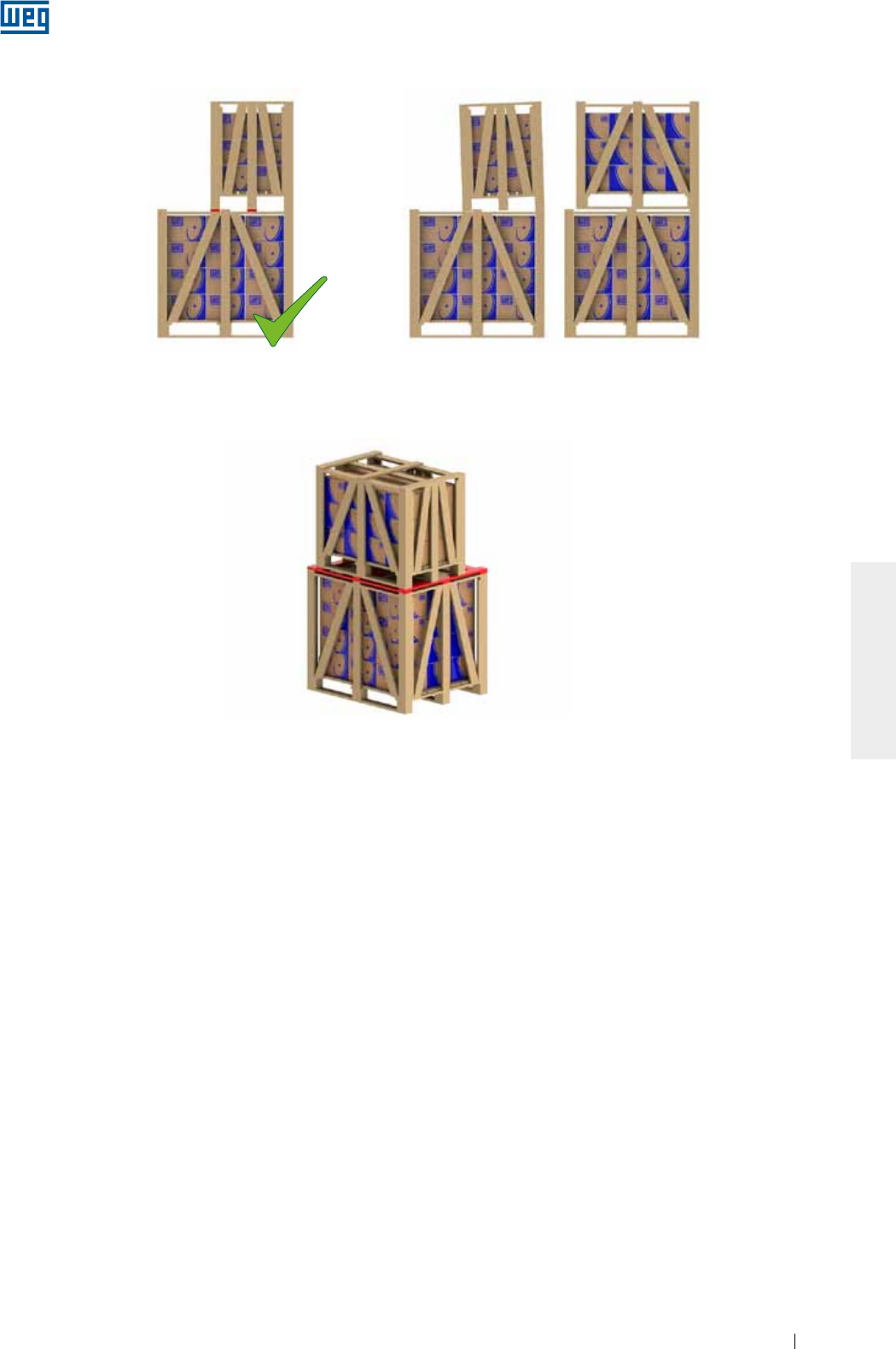
www.weg.net
Elektrische Motoren 185
DEUTSCH
Bild 5.5 - Einsatz von zusätzlichen leisten zum stapeln von lattenkisten
5.3. LAGER
5.3.1. Fettgeschmierte Wälzlager
Um eine Oxidation der Wälzlager während der Lagerungszeit zu vermeiden und wieder eine gleichmäßige
Fettverteilung zu erlangen, soll der Läufer mindestens einmal pro Monat etwas von Hand gedreht werden
(mind. 5 Umdrehungen) und immer in einer anderen Position zum Stillstand kommen.
Bemerkung: Transportsicherung / Läuferfeststellvorrichtung (wenn vorhanden) müssen vor der Drehung der
Welle entfernt und für jeden zukünftigen Transport wieder eingebaut werden.
Vertikal aufgestellte Motoren können in der vertikalen oder in der horizontalen Lage gelagert werden.
Wird der Motor mit nachschmierbaren Wälzlagern länger als 6 Monate gelagert, müssen die Lager, gemäß Pkt.
8.2, vor Inbetriebnahme neu gefettet werden.
Wird der Motor während 2 Jahre oder länger gelagert, müssen die Wälzlager vor Inbetriebnahme gewechselt
bzw. ausgebaut und mit Waschbenzin gründlich gewaschen, überprüft, getrocknet und nach dem
sachgemäßen Wiedereinbau neu gefettet werden (siehe Pkt. 8.2).
5.3.2. Ölgeschmierte Wälzlager
Der Motor soll in seiner Betriebslage mit Lageröl in den Lagern gelagert werden. Der Ölstand muss sich auf
halber Sichtglashöhe befinden. Während der Lagerungszeit, muss jeden Monat die Transportsicherung von der
Welle entfernt und der Läufer etwas von Hand gedreht werden (mind. 5 Umdrehungen) um eine Oxidation der
Wälzlager zu vermeiden. Danach muss die Transportsicherung wieder neu eingebaut werden. Wird der Motor
länger als 6 Monate gelagert, müssen die Lager und der Ölstand vor der Inbetriebnahme gemäß Anleitung
kontrolliert werden (siehe Pkt. 8.2). Wird der Motor während 2 Jahre oder länger gelagert, müssen die
Wälzlager vor der Inbetriebnahme gewechselt bzw. ausgebaut und mit Waschbenzin gründlich gewaschen,
überprüft, getrocknet und nach dem sachgemäßen Wiedereinbau mit Lageröl befüllt werden (siehe Pkt. 8.2).
Das Öl von vertikal aufgestellten Motoren, die in horizontaler Lage transportiert werden, muss abgelassen
werden, um einen Auslauf des Öles während des Transportes zu vermeiden. Nach dem Transport müssen
diese Motoren wieder in vertikaler Lage gelagert und das Lageröl muss wieder auf halber Sichtglashöhe
aufgefüllt werden.
Bild 5.3 - Richtig gestapelt Bild 5.4 - Falsch gestapelt
X
4. Soll eine kleinere Kiste auf eine größere gestapelt werden, müssen Querleisten zwischen den Kisten gelegt werden, wenn die untere
Kiste nicht das Gewicht der oberen kleineren Kiste trägt (siehe Bild 5.5). Diese Situation kommt allgemein bei der Stapelung von
Lattenkisten ab den Baugrößen IEC 225S/M (NEMA 364/5T) Baugrößen vor.
3. Die Füße der oberen Kiste müssen immer auf den Holzunterlegklötzen (Bild 5.3) und nicht auf den Stahlbänden der Kiste aufliegen und
niemals ohne Abstützung bleiben;
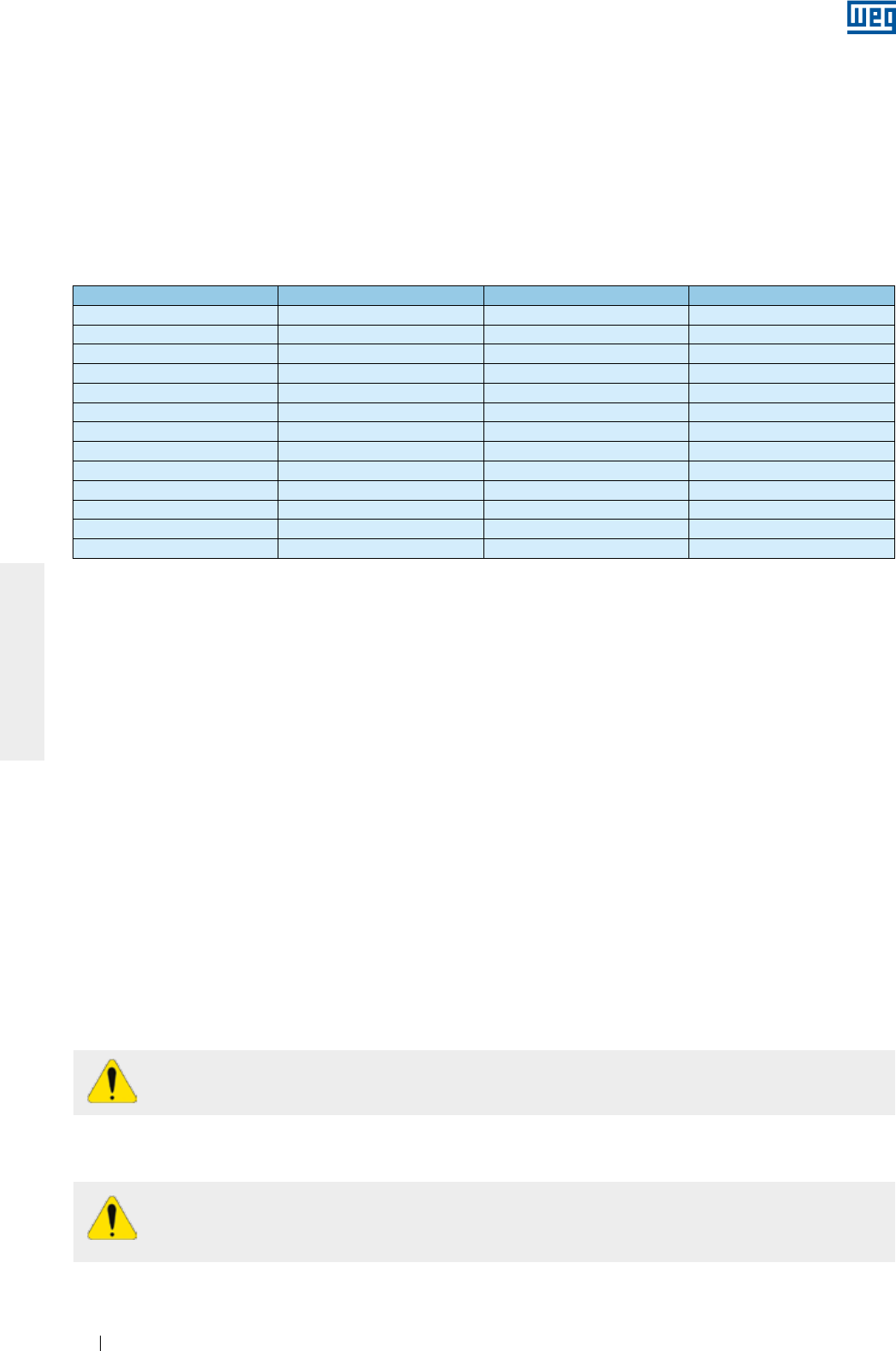
www.weg.net
Elektrische Motoren186
DEUTSCH
5.3.3. Schmierölnebel geschmierte Wälzlager
Wälzlager Ölmenge (ml) Wälzlager Ölmenge (ml)
6201 15 6309 65
6202 15 6311 90
6203 15 6312 105
6204 25 6314 150
6205 25 6315 200
6206 35 6316 250
6207 35 6317 300
6208 40 6319 350
6209 40 6320 400
6211 45 6322 550
6212 50 6324 600
6307 45 6326 650
6308 55 6328 700
Der Motor muss immer ohne Öl gehandhabt werden. Wird das System der Nebelschmierung nicht sofort nach
der Installation der Maschine eingeschaltet, muss das Wälzlager mit Lageröl gefüllt werden um eine Oxidation
zu vermeiden. Auch während der Lagerungszeit soll der Läufer (mind. 5 Umdrehungen) mindestens einmal pro
Monat etwas von Hand gedreht werden und immer in einer anderen Position zum Stillstand kommen.
Vor einem Maschinenstart, muss das Öl komplett abgelassen und das System der Nebelschmierung
eingeschaltet werden.
5.3.4. Gleitlager
Der Motor soll in seiner Betriebslage mit Lageröl in den Lagern gelagert werden. Der Ölstand muss sich auf
halber Sichtglashöhe befinden. Während der Lagerungszeit, muss alle zwei Monate die Transportsicherung von
der Welle entfernt werden. Anschließend den Läufer bei einer Drehzahl von ca. 30 1/min drehen um wieder eine
gleichmäßige Ölverteilung zum Schutz gegen Oxidation zu erlangen und um die Lager im einwandfreien
Betriebszustand zu halten. Danach muss die Transportsicherung wieder neu eingebaut werden.
Die Transportsicherung muss immer zum Transport des Motors verwendet werden. Wird der Motor länger als 6
Monate gelagert, müssen die Lager, gemäß Pkt. 8.2, vor Inbetriebnahme neu mit Lageröl befüllt werden.
Tabelle 5.2 - Ölmenge pro Wälzlager
5.4. ISOLATIONSWIDERSTAND
Während der Lagerungszeit, muss der Isolationswiderstand der Wicklungen in regelmäßigen Zeitabständen
und vor der Inbetriebnahme gemessen und protokolliert werden. Wird ein Abfall des Isolationswiderstandes
festgestellt, müssen seine Ursachen und die Lagerungsbedingungen überprüft und evtl. verbessert werden.
5.4.1. Messung des Isolationswiderstandes
Der Isolationswiderstand muss immer in einem nichtexplosionsgefährdeten Bereich gemessen
werden.
Um einen elektrischen Schlag zu vermeiden, müssen die Motorklemmen vor und nach jeder
Messung geerdet werden. Erden Sie die Kondensatoren (falls geliefert) um Ihre komplette
Entladung zu erlauben bevor Sie die Messung vornehmen.
Der Isolationswiderstand wird mit einem Megohmmeter gemessen. Die Maschine muss sich im kalten Zustand
befinden und vom Netzanschlusskabel im Klemmenkasten getrennt sein.
Bei Schmierölnebel geschmierten Wälzlagern (oil mist), soll der Motor immer, unabhängig von der Bauform, in
horizontaler Lage mit Lageröl ISO VG 68 in der Menge wie in der Tabelle 5.2 angegeben, gelagert werden.
Nach der Öleinfüllung den Läufer (mind. 5 Umdrehungen) etwas von Hand drehen. Während der Lagerung die
Transportsicherung / Läuferfeststellvorrichtung (wenn vorhanden) entfernen und den Läufer (mind. 5
Umdrehungen) mindestens einmal pro Monat etwas von Hand drehen und immer in einer anderen Position zum
Stillstand kommen lassen. Wird der Motor etwa 2 Jahre oder länger gelagert, müssen die Wälzlager vor der
Inbetriebnahme gewechselt oder ausgebaut und mit Waschbenzin gründlich gewaschen, überprüft, getrocknet
und nach dem sachgemäßen Wiedereinbau gemäß Tabelle 5.2 mit Öl befüllt werden.
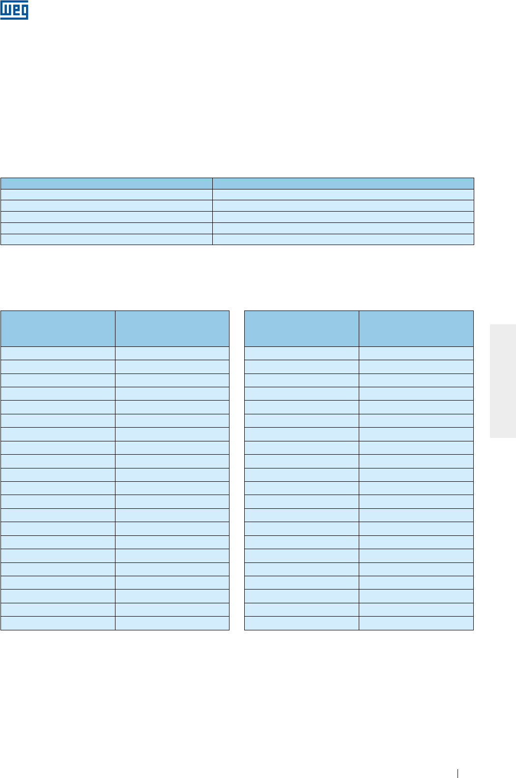
www.weg.net
Elektrische Motoren 187
DEUTSCH
Tabelle 5.3 - Angelegte Spannung zur Messung des Isolationswiderstandes
Motorbemessungsspannung (V) Angelegte Spannung zur Isolationswiderstandsmessung (V)
< 1000V 500
1000 - 2500 500 - 1000
2501 - 5000 1000 - 2500
5001 - 12000 2500 - 5000
> 12000 5000 - 10000
Der zu messende Isolationswiderstand bezieht sich auf eine Wicklungstemperatur von 40 °C. Soll die
Isolationswiderstandsmessung bei anderer Temperatur durchgeführt werden, muss der gemessene Wert auf
40 ºC umgerechnet werden. Siehe Tabelle 5.4:
Tabelle 5.4 - Korrekturfaktor des Isolationswiderstandes auf 40 ºC umgerechnet
Wicklungstemperatur zum
Zeitpunkt der Messung °C)
Korrekturfaktor des
Isolationswiderstandes auf
40 ºC umgerechnet
10 0,125
11 0,134
12 0,144
13 0,154
14 0,165
15 0,177
16 0,189
17 0,203
18 0,218
19 0,233
20 0,250
21 0,268
22 0,287
23 0,308
24 0,330
25 0,354
26 0,379
27 0,406
28 0,435
29 0,467
30 0,500
Wicklungstemperatur zum
Zeitpunkt der Messung °C)
Korrekturfaktor des
Isolationswiderstandes auf
40 ºC umgerechnet
30 0,500
31 0,536
32 0,574
33 0,616
34 0,660
35 0,707
36 0,758
37 0,812
38 0,871
39 0,933
40 1,000
41 1,072
42 1,149
43 1,231
44 1,320
45 1,414
46 1,516
47 1,625
48 1,741
49 1,866
50 2,000
Es wird empfohlen, den Isolationswiderstand der einzelnen Phasen (wenn möglich) separat zu messen, was
einen Vergleich des Isolationswiderstandes zwischen den Phasen erlaubt. Während der Messung einer Phase
müssen die anderen Phasen geerdet sein. Eine gleichzeitige Messung des Isolationswiderstandes aller Phasen
(verkettet) gibt nur Informationen über den Isolationswiderstand gegen Erde und nicht zwischen den einzelnen
Phasen wieder.
Versorgungskabel, Schalter, Kondensatoren und andere extern am Motor angeschlossenen Geräte können die
Messung des Isolationswiderstandes beeinflussen. Aus diesem Grunde müssen während der Messung des
Isolationswiderstandes die extern angeschlossenen Geräte vom Motor getrennt und ordnungsgemäß geerdet
sein. Die Messung des Isolationswiderstandes der Wicklung muss mit einem Megohmmeter unter
Berücksichtigung der Motorbemessungsspannung ca. 1 Minute nach Anlegen der Gleichspannung wie folgt
(Tabelle 5.3), vorgenommen werden:
www.weg.net
Elektrische Motoren188
DEUTSCH
Die in o. g. Tabelle angegebenen Werte sind nur als Richtwerte anzusehen. Der Isolationswiderstand ist in
regelmäßigen Zeitabständen zu messen und aufzuzeichnen um einen künftigen Vergleich und eine zuverlässige
Aussage über den Isolationswiderstand der Maschine zu bekommen.
Unterschreitet der gemessene Isolationswiderstandswert die oben geforderten Isolationswiderstandswerte, ist
zu überprüfen, ob die Motorklemmen feucht oder verschmutzt sind (gegebenenfalls sind die
Netzanschlusskabel im Klemmenkasten vom Motor zu trennen und eine erneute Messung des
Isolationswiderstandes ist durchzuführen).
Sollte das Ergebnis immer noch negativ sein, wird empfohlen, den Motor auszubauen und zu einer WEG-
Kundendienststelle zur Überprüfung und entsprechender Reparatur zu bringen. Diese Arbeiten werden nicht
von der Gewährleistung abgedeckt.
Zur Trocknung der Wicklung, siehe Pkt. 8.4.
Tabelle 5.5 - Beurteilung des Isolationssystems
Grenzwerte des
Isolationswiderstandes für
Bemessungsspannungen bis
1,1 kV (M)
Grenzwerte des
Isolationswiderstandes für
Bemessungsspannungen
über 1,1 kV (M)
Beurteilung
Bis 5 Bis 100 Gefahr! Der Motor darf nicht unter diesen
Bedingungen betrieben werden.
Zwischen 5 und 100 Zwischen 100 und 500 zufriedenstellend
Zwischen 100 und 500 Über 500 gut
Über 500 Über 1000 sehr gut
Der Zustand der Isolation wird durch einen Vergleich des gemessenen Wertes mit den Werten in der
nachstehenden Tabelle 5.5 (auf 40 °C bezogen) bewertet:
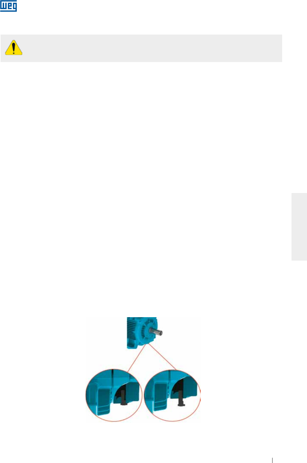
www.weg.net
Elektrische Motoren 189
DEUTSCH
6. INSTALLATION
Es wird vorausgesetzt, dass die Arbeiten der Installation von qualifiziertem Personal mit
ausreichenden Kenntnissen über die einschlägigen Normen und Sicherheitsvorschriften des
betreffenden Landes ausgeführt werden.
Vor der Installation müssen folgende Punkte überprüft werden:
1. Isolationswiderstand: müssen annehmbare Werte aufweisen. Siehe Pkt. 5.4.
2. Wälzlager:
a. Wälzlager: werden Oxidationszeichen festgestellt, müssen die Lager gewechselt werden. Weisen die Wälzlager
keine Oxidationszeichen auf, müssen sie gemäß Pkt. 8.2 geschmiert werden. Wird der Motor während 2 Jahre
oder länger gelagert, müssen die Wälzlager vor der Inbetriebnahme des Motors gewechselt werden;
b. Gleitlager: wird der Motor länger als die vorgeschriebenen Ölwechsel-Intervalle gelagert, muss das Lageröl vor
Inbetriebnahme des Motors gewechselt werden. Bitte nicht vergessen, das Mittel zur Entfeuchtung vorher zu
entfernen. Wenn der Motor ohne Öl gelagert wurde, ist wieder neues Lageröl vor der Inbetriebnahme des
Motors, einzufüllen. Weitere Informationen über dieses Vorgehen können Sie in Pkt. 8.2 finden.
3. Betriebsbedingungen der Anlasskondensatoren: Werden Einphasenmotoren länger als zwei Jahre gelagert,
müssen die Anlasskondensatoren vor der Inbetriebnahme gewechselt werden, da sie nach längerer
Lagerungszeit ihre Betriebseigenschaften verlieren können.
4. Klemmenkästen:
a. Das Innere des Klemmenkastens muss trocken, sauber und außerdem frei von Staub sein;
b. Die Klemmen müssen frei von Schmutz und Oxidation gehalten werden und ordnungsgemäß geschaltet sein.
Siehe Pkt. 6.9 und 6.10;
c. Nicht benutzte Kabeleinführungen müssen ordnungsgemäß abgedichtet sein. Der Klemmenkastendeckel
muss mit den vorgesehenen Schrauben befestigt und die Dichtungen müssen funktionsfähig sein, um den auf
dem Leistungsschild angegebenen Schutzgrad einzuhalten.
5. Kühlung: die Kühlrippen sollten stets frei von Staub sein. Die Luftein- und Luftaustritte dürfen nicht abgedeckt
oder verstopft sein. Der empfohlene Einbauabstand zwischen der Lufteintrittsöffnung des Motors und einer Wand
muss wenigstens ¼ des Durchmessers der Lufteintrittsöffnung betragen. Es muss genügend Raum für die
Reinigung vorgesehen werden. Siehe Pkt. 6.
6. Kupplung: Die Transportsicherung/Läuferfeststellvorrichtung (wenn vorhanden) und der Korrosionsschutz am
Wellenende und am Flansch dürfen erst unmittelbar vor der Motoraufstellung entfernt werden. Die
Transportsicherung/Läuferfeststellvorrichtung ist sicher für künftige Transporte aufzubewahren. Siehe Pkt. 6.4.
7. Kondenswasserablassbohrung: Der Motor muss so aufgestellt werden, dass der Wasserablass erreichbar ist und
die Wasserablassbohrungen sich an der niedrigsten Stelle der Maschine befinden. Ist der Wasserablassstopfen
mit einem Pfeil am Kopf versehen und wird er in horizontaler Lage eingebaut, muss der Pfeil immer nach unten
zeigen. In Umgebungen mit hoher Luftfeuchtigkeit, können die Kondenswasserablassstopfen der Motoren mit
Schutzgrad IP55 auch in offener Position geliefert werden (siehe Bild 6.1). Die Kondenswasserablassstopfen der
Motoren mit dem Schutzgrad IP56, IP65 oder IP66 müssen immer geschlossen sein (siehe Bild 6.1). Die Stopfen
dürfen während der Wartung der Maschine geöffnet werden.
Bei Motoren mit Schmierölnebel geschmierten Wälzlagern (Oil Mist) sind die Ölablassbohrungen an eine
spezifische Ölsammelleitung angeschlossen (siehe Bild 6.12).
Bild 6.1 - Position der Gummiablassstopfen in geschlossener und geöffneter Stellung
Kondenswasserablassstopfen
geschlossen
Kondenswasserablassstopfen
geöffnet
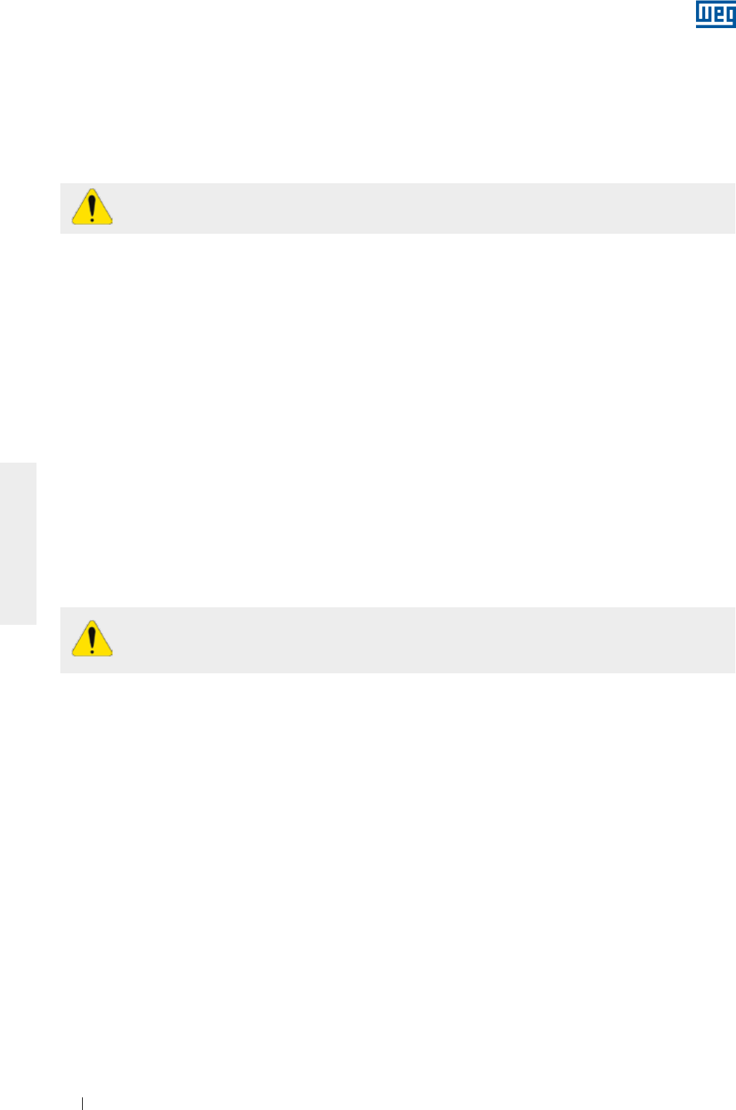
www.weg.net
Elektrische Motoren190
DEUTSCH
Vor dem Motorstart die Passfeder entfernen oder sicher befestigen (nur vor dem Betrieb im Leerlauf).
Die zum Antrieb der Last vorkommenden Beanspruchungen sind als Bestandteil zur
Fundamentauslegung anzusehen.
Der Anwender ist für die Fundamentauslegung verantwortlich.
8. Zusätzliche Empfehlungen:
a. Den Drehsinn der Maschine, von der Last abgekuppelt, überprüfen;
b. Werden Motoren im Freien oder in vertikaler Position mit Wellenende nach unten aufgestellt, ist ein zusät-
zlicher Schutz vorzusehen, um das Eindringen von Flüssigkeiten oder Feststoffen in das Innere des Motors
zu verhindern, z. B. mit einem Schutzdach;
c. Werden Motoren im Freien oder in vertikaler Position mit Wellenende nach oben aufgestellt, muss ein Was-
serabschleuderring (
water slinger ring
) eingebaut sein, um das Eindringen von Wasser am Wellendurch-
gang zu verhindern.
6.1. FUNDAMENTE FÜR DEN MOTOR
Das Fundament ist die natürliche Struktur oder die vorbereitete Basis, die zur Aufstellung des Motors dient, um
den Beanspruchungen des Maschinensatzes zu widerstehen und einen sicheren und schwingungsfreien
Betrieb zu gewährleisten. Bei der Fundamentauslegung müssen umgebende Strukturen berücksichtigt werden,
um die mechanischen Beanspruchungen der anderen aufgestellten Maschinen nicht zu behindern und
sicherzustellen, dass keine Schwingungen über die Struktur übertragen werden.
Das Fundament für die Motoraufstellung muss eben sein und seine Auswahl und Auslegung muss folgende
Eigenschaften berücksichtigen:
a) Die Betriebseigenschaften der aufzustellenden Maschine, die anzutreibende Last, der Maschineneinsatz, die
max. zugelassenen Deformationen der anzutreibenden Maschine und der zugelassene Schwingungspegel
(z. B., Motoren mit reduziertem Schwingungspegel, Planflächigkeit der Motorfüße, Konzentrizität der
Flansche, Axial- und Radiallasten, usw.).
b) Die Betriebseigenschaften der benachbarten Maschinen, ihren Erhaltungszustand, max. zu erwartende
Lasten, Fundament- und Befestigungsarten, der von den benachbarten Maschinen übertragene
Schwingungspegel, usw.
Wird der Motor mit einer Nivellier-/Ausrichtschraube geliefert, muss in der Basis eine Fläche vorgesehen werden
die eine ordnungsgemäße Nivellierung/Ausrichtung ermöglicht.
Gemäß Bild 6.2 können können die Beanspruchungen des Fundamentes nach folgenden Gleichungen
bestimmt werden:
F1 = 0,5 * g * m - (4 * Cmax / A)
F2 = 0,5 * g * m + (4 * Cmax / A)
Wo:
F1 und F2 = die Reaktion der Füße auf die Basis (N);
g = gravitationsbeschleunigung (9,8 m/s2);
m = motormasse (kg);
Cmax. = Max. Drehmoment (Nm);
A = abstand zwischen den Befestigungsbohrungen an den Motorfüßen (Frontansicht) (m).
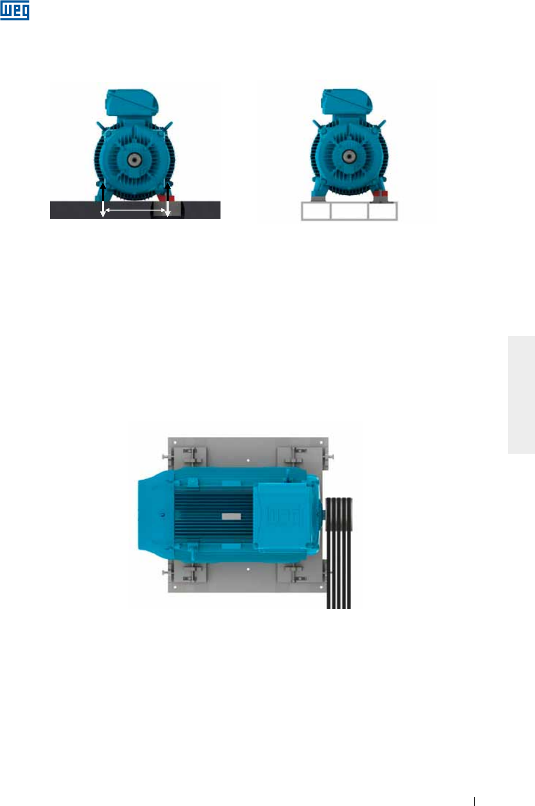
www.weg.net
Elektrische Motoren 191
DEUTSCH
Die Motoren können auf folgende Basen aufgestellt werden:
g Betonbasis: allgemein werden Betonbasen zur Aufstellung von großen Motoren verwendet (siehe Bild 6.2);
g Metallische Basis: allgemein werden metallische Basen zur Aufstellung von kleineren Motoren verwendet (sie
he Bild 6.3).
Bild 6.3 - Motor auf metallische Basis aufgestellt
Bild 6.2 - Motor auf Betonbasis aufgestellt
Beton- und metallische Basen können mit Spannschienen ausgestattet werden. Diese Fundamentart wird
hauptsächlich für Motoren mit Riemenantrieb eingesetzt. Die Fundamentart ermöglicht einen schnelleren Ein-
und Ausbau des Motors, als auch eine genaue Einstellung der Riemenspannung. Die untere Riemenseite muss
immer den Antrieb herstellen. Die Spannschiene an der Seite der Riemenscheibe muss so eingebaut werden,
dass sich die riemenseitige Spannschraube zwischen Motor und der angetriebenen Maschine befindet. Bei der
anderen Spannschiene muss sich die Spannschraube in entgegengesetzter (diagonaler) Lage befinden. Sie
Bild 6.4.
Um die Aufstellung des Motors zu erleichtern, kann diese Fundamentart mit:
g Vorsprüngen und/oder Aussparungen;
g Ankerschrauben mit losen aufgelegten Ankerplatten;
g Ankerschrauben mit Beton vergossen;
g Nivellierschrauben;
g Positionierschrauben;
g Eisen- oder Stahlblöcke mit planflächiger Oberfläche, versehen sein.
Bild 6.4 - Motor auf Spannschienen aufgestellt
Nach der Aufstellung des Motors sind alle bearbeiteten Flächen - Wellenende, Flanschoberflächen, usw. sind
mit einem Korrosionsschutz, oder ähnlichem Material versehen.
F1F1
F2F2
A
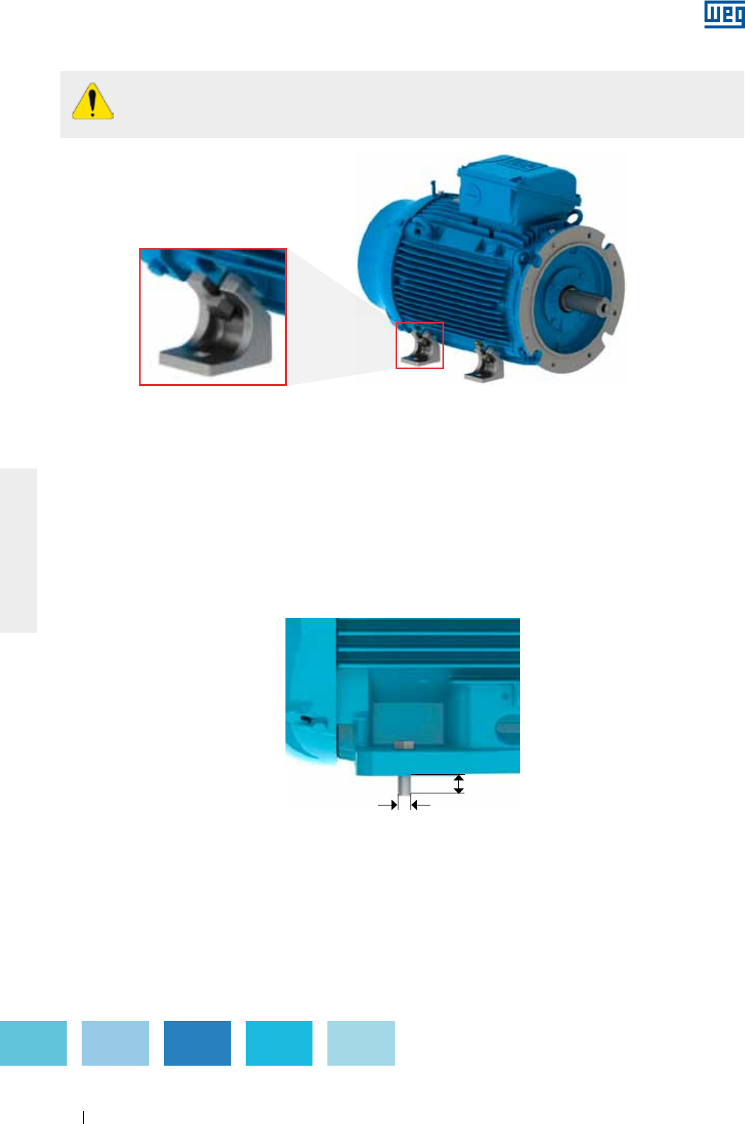
www.weg.net
Elektrische Motoren192
DEUTSCH
6.2. MOTORAUFSTELLUNG
6.2.1. Fußbefestigte Motoren
Die Maßzeichnungen der Fußbohrungen nach Norm IEC oder NEMA können dem entsprechenden technischen
Katalog entnommen werden. Der Motor muss ordnungsgemäß montiert und genau mit der angetriebenen
Maschine ausgerichtet/nivelliert werden, um übermäßige Schwingungen, vorzeitige Lagerschäden und
letztendlich sogar eine Wellenverbiegung/Wellenbruch zu vermeiden.
Für nähere Einzelheiten, siehe Pkt. 6.3 und 6.6.
Es wird empfohlen, dass die Befestigungsschrauben eine Mindesteinschraubtiefe von 1,5 x
Schraubendurchmesser haben müssen. Bei stärker beanspruchten Anwendungen kann die Auswahl von
Schrauben mit längerem Gewinde notwendig sein. Bild 6.6 zeigt die Befestigung von Motoren mit Füßen mit
Angabe der Mindesteinschraubtiefe.
Bild 6.6 - Darstellung der Befestigung des Motors mit Füßen
L = 1.5 x D
D
Motoren ohne Füße (Flanschausführung), werden mit einer Transportvorrichtung geliefert. Siehe Bild
6.5 - Einzelheiten der Vorrichtungen, die zum Transport von Motoren ohne Füße eingesetzt werden.
Diese Transportvorrichtung muss vor der Installation des Motors entfernt werden.
Bild 6.5 - Einzelheiten der Vorrichtungen, die zum Transport von Motoren ohne Füße eingesetzt werden
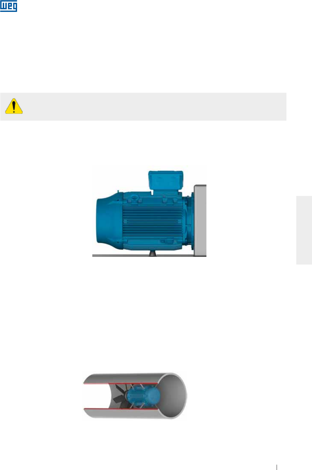
www.weg.net
Elektrische Motoren 193
DEUTSCH
6.2.2. Flanschbefestigte Motoren
Die Maßzeichnungen der Flansche nach Norm IEC oder NEMA, können dem entsprechenden technischen
Katalog entnommen werden.
Die Fläche der angetriebenen Maschine muss plan auf dem Motorflansch aufliegen und geeignete Bohrungen
aufweisen um eine ordnungsgemäße Konzentrizität der Bauteile sicherzustellen. Je nach Bauart des Flansches,
kann die Befestigung vom Motor in Richtung zur Basis (Flansch FF (IEC)) oder D oder von der Basis in Richtung
zum Motor (Flansch C (DIN oder NEMA)) vorgenommen werden.
Zur Befestigung an dem Motorflansch, muss die Schraubenlänge die Flanschdicke der anzutreibenden
Maschine und die Einschraubtiefe in dem Motorflansch berücksichtigt werden.
Ist der Flansch mit Gewindedurchgangsbohrungen versehen, darf die Gewindelänge der
Motorbefestigungsschrauben die Materialstärke des Flansches nicht überschreiten, um dadurch
keine Beschädigung der Motowicklung im Inneren zu verursachen.
Zur Befestigung des Motors auf der Basis wird empfohlen, dass die Befestigungsschrauben eine
Mindesteinschraubtiefe von 1,5 x Schraubendurchmesser haben sollten. Bei stärker beanspruchten
Anwendungen kann die Auswahl von Schrauben mit längerem Gewinde notwendig sein.
Größere Motoren, oder Motoren mit erschwerten Betriebsbedingungen, sollen außer der Flanschbefestigung,
auch über einen Fuß abgestützt werden (pad mounted). Der Motor darf niemals auf seine Kühlrippen
abgestützt werden. Siehe Bild 6.7.
Bild 6.7 - Darstellung der Befestigung eines Motors mit Flansch und mit Fußabstützung
Bei Motoren, wo im Inneren des Flansches sich z.B. Öl oder andere Flüssigkeiten ansammeln können, muss
durch eine Abdichtung sichergestellt werden, dass ein Eindringen von Flüssigkeiten in das Motorinnere
verhindert wird.
6.2.3. B30 Pad-mounted Motoren
Diese Befestigungsart wird normalerweise in Entlüftungsrohren eingesetzt. Die Befestigung wird über
Gewindebohrungen am Motorgehäuse mit Gewindestangen vorgenommen. Die Maßzeichnungen können dem
entsprechenden elektronisch-technischen Katalog oder dem Produktkatalog entnommen werden.
Die Gewindestangen/Schrauben des Motors müssen die Maße der Entlüftungsrohre und die Einschraubtiefe im
Motorgehäuse berücksichtigen. Die Gewindestangen und die Wand des Entlüftungsrohres müssen
ausreichende Steifigkeit aufweisen um zu hohe Schwingungen des Maschinensatzes (Motor + Lüfter) zu
vermeiden. Bild 6.8 stellt die Befestigung über Gewindestangen am Motorgehäuse in einem Entlüftungsrohr dar
(Pad mounted).
Bild 6.8 - Befestigungsdarstellung des Motors in einem Entlüftungsrohr
www.weg.net
Elektrische Motoren194
DEUTSCH
6.3. AUSWUCHTEN
Schlecht ausgewuchtete Maschinen haben übermäßige Schwingungen zur Folge und können zu vorzeitigen
Lagerschäden und letztendlich sogar zu einem Wellenbruch führen WEG- Motoren werden immer mit halber
Passfeder dynamisch ausgewuchtet, geliefert. Ist ein Feinauswuchten des Motors gewünscht, muss diese
Forderung im Auftrag angegeben werden.
Die Übertragungselemente, wie Riemenscheiben, Kupplungen, usw. müssen vor dem Anbau an die
Motorwelle entsprechend ausgewuchtet werden bzw. sein.
Werden Motoren ohne Übertragungselement z.B. im Leerlauf betrieben, muss die Passfeder
entfernt oder ordnungsgemäß befestigt werden, um Unfälle zu vermeiden.
Bei dem Einsatz von direkter Kupplung niemals Zylinderrollenlager verwenden, es sei denn, dass
genügend Radiallast sichergestellt ist.
Motoren mit Gleitlagern müssen direkt mit der angetriebenen Maschine oder über ein
Untersetzungsgetriebe gekuppelt werden. Ein Betrieb über Riemenscheibe und Riemen ist nicht
erlaubt.
Übermäßiges Spannen des Antriebsriemens kann einen unerwarteten Unfall und den Bruch der
Welle verursachen.
Die Wuchtgüte des Motors entspricht den einschlägigen Normen jeder Produktreihe.
Max. vorkommende Abweichungen der Wuchtgüte müssen im Installationsbericht eingetragen werden.
6.4. ÜBERTRAGUNGSELEMENTE
6.4.1. Direkte Kupplung
Die Übertragungselemente müssen so gewählt werden, dass sie ausschließlich das Drehmoment des Motors
auf die angetriebene Maschine übertragen. Während des Anbaus der Übertragungselemente müssen folgende
Punkte berücksichtigt werden:
g Zum Anbau und Abbau der Übertragungselemente sind immer geeignete Werkzeuge einsetzen, um so
Schäden am Motor zu vermeiden;
g Immer wenn möglich, sind flexible Kupplungen zu verwenden, die kleine Ausrichtungsungenauigkeiten
während des Betriebes aufnehmen können;
g Die im Herstellerkatalog angegebenen zulässigen Belastungen und Drehzahlgrenzen des Motors dürfen nicht
überschritten werden;
g Eine genaues Ausrichten/Nivellieren zwischen Motor und angetriebener Maschine, ist gemäß Pkt. 0 bzw. 6.6.
einzuhalten.
Die direkte Kupplung wird angewendet, wenn die Motorwelle die Arbeitsmaschine ohne Einsatz von
Übertragungselementen antreiben soll. Aus Kostengründen, Raumersparnis, der Verhinderung von
Riemenschlupf und der Unfallverhütung, sollte immer die direkte Kupplung von Motor und Arbeitsmaschine
bevorzugt werden.
6.4.2. Kupplung über Getriebe
Die Kupplung über Getriebe wird eingesetzt, wo ein Untersetzungsverhältnis gefordert wird.
Die Motorwelle und die Welle der angetriebenen Maschine müssen genau gegeneinander ausgerichtet sein und
parallel gegeneinander liegen (für zylindrische geradverzahnte Getriebe) und der Zahneingriffswinkel muss
besonders für Kegelgetriebe und Schneckengetriebe korrekt sein.
6.4.3. Antrieb über Riemenscheiben und Riemen
Der Riementrieb wird meistens da eingesetzt, wo ein Untersetzungsverhältnis zwischen Motor und
angetriebener Maschine gefordert wird.
6.4.4. Kupplung von Motoren mit Gleitlagern
Motoren mit Gleitlagern sind mit 3 (drei) Marken (rote Punkte) auf dem Wellenende versehen. Die
Zentralmarkierung gibt das magnetische Zentrum des Läufers wieder, während die beiden Außenmarken die
Grenzen der erlaubten Axialbewegung des Läufers anzeigen. Siehe Bild 6.9.
Während des Betriebes muss der Pfeil genau über der Zentralmarkierung (rot gestrichen) stehen, was
bedeutet, dass der Motor sich in seinem magnetischen Zentrum befindet.
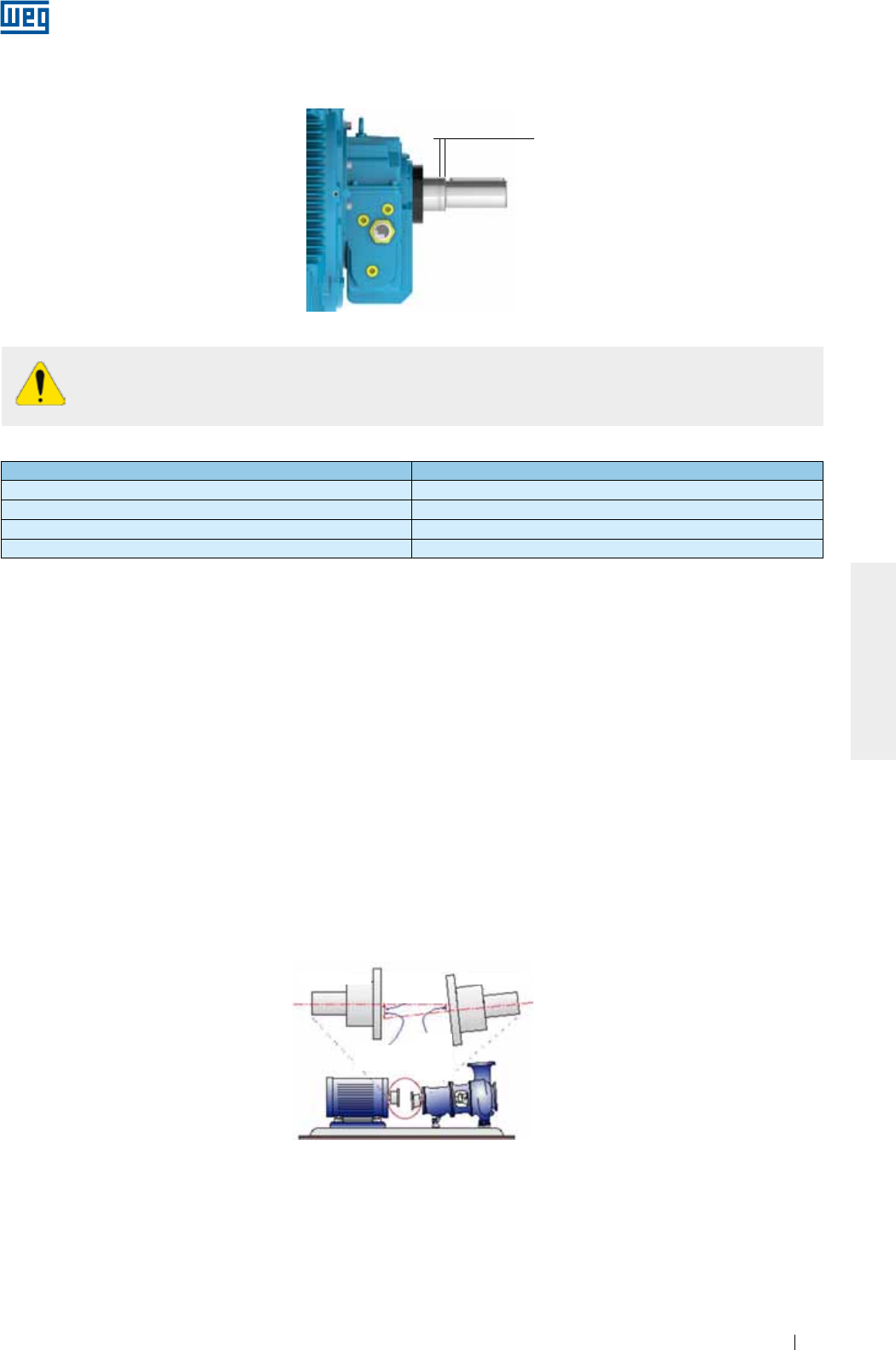
www.weg.net
Elektrische Motoren 195
DEUTSCH
AXIALHUB
Bild 6.9 - Axialhub eines mit Gleitlagern ausgestatteten Motors
Tabelle 6.1 - Axialhub für Gleitlager
Lagergröße Axialhub total (mm)
9* 3 + 3 = 6
11* 4 + 4 = 8
14* 5 + 5 =10
18 7,5 + 7,5 = 15
* Für Motoren gemäß Norm API 541, beträgt der totale Axialhub 12.7 mm.
Die von WEG eingesetzten Gleitlager sind nicht für ständige Axialbeanspruchungen ausgelegt.
Eine ständige Axialbeanspruchung der Motorwelle auf das Lager ist verboten.
6.5. NIVELLIEREN
Das Nivellieren des Motors muss durchgeführt werden um evtl. Höhenabweichungen zu korrigieren, die im
Herstellungsverfahren wegen unterschiedlichen Materialen verursacht werden können. Das Nivellieren kann mit
einer am Motor oder Flansch befestigten Nivellierschraube oder Unterlegen von feinen Ausgleichsscheiben
vorgenommen werden. Nach dem Nivellieren darf der Höhenunterschied zwischen der Montagebasis und dem
Motor nicht größer als 0,1 mm sein. Wird die metallische Basis zur Ausrichtung des Motorwellenendes mit der
Welle der angetriebenen Maschine eingesetzt, so muss diese mit der Betonbasis nivelliert werden.
Es wird empfohlen die max. Abweichungen beim Nivellieren zu erfassen und im Installationsbericht einzutragen.
6.6. AUSRICHTEN
Das Ausrichten zwischen Antriebsmaschine und angetriebener Maschine ist einer der Variablen, die die
Lebensdauer des Motors am stärksten beeinflussen können. Ein Versatz zwischen den Kupplungen erzeugt
hohe Lasten, die die Lebensdauer der Lager verkürzen, hohe Schwingungen verursachen und letztendlich
sogar zu einem Wellenbruch führen können. Bild 6.10 zeigt den Versatz zwischen dem Motor und der
angetriebenen Maschine.
Bild 6.10 - Typische Ausrichtungsfehler
Zur Beurteilung der Kupplung muss der in Tabelle 6.1 max. Axialhub des Lagers berücksichtig
werden. Der Axialhub der angetriebenen Maschine und der Kupplung beeinflussen den max.
Axialhub des Lagers.
Ausrichtungsfehler
Motor-
versatz
(mm)
Versatz der
angetrie-
benen
Maschine
(mm)
Antriebswelle Angetriebene Welle
Um ein genaues Ausrichten zu gewährleisten, müssen immer geeignete Werkzeuge und Vorrichtungen, wie
Messuhren oder Laser-Ausrichter, eingesetzt werden. Die Wellen von Motor und der angetriebenen Maschine
müssen axial und radial ausgerichtet werden.
Die Messung mit einer Messuhr darf, gemäß Bild 6.11, keine größere Ungenauigkeit als 0,03 mm bezogen auf
eine komplette Umdrehung, aufweisen. Es muss ein Luftspalt zwischen den Kupplungen vorgesehen werden
um die unterschiedlichen Wärmeausdehnungen der Bauteile während des Betriebes, unter Berücksichtigung
der Angaben des Kupplungsherstellers, auszugleichen.
Beim Anfahren oder während des Betriebes darf sich die Motorwelle frei zwischen den beiden Außenmarken
verschieben, was durch das Aufbringen einer Axiallast auf die Motorwelle verursacht wird. Aber eine ständige
Axialbeanspruchung der Motorwelle auf das Lager ist verboten.
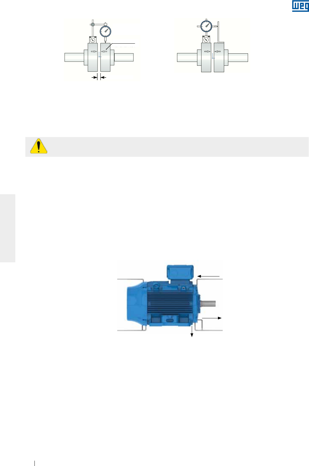
www.weg.net
Elektrische Motoren196
DEUTSCH
Wird das Ausrichten zwischen dem Motor und der angetriebenen Maschine mit einem Laserinstrument
vorgenommen, müssen immer die Empfehlungen des Messinstrumentenherstellers berücksichtigt werden.
Der Ausrichtungszustand muss immer bei Umgebungstemperatur und Betriebstemperatur der Maschinen
überprüft werden.
Die Kontrolle des Ausrichtungszustandes muss in regelmäßigen Abständen durchgeführt werden.
Um Lagerschäden beim Riemenbetrieb zu vermeiden, sind die Wellen von Motor und der angetriebenen
Maschine so auszurichten, dass die Riemenscheiben parallel zueinander laufen. Nicht parallel laufende
Riemenscheiben übertragen auf den Lagersitz hohe Spannungen, wechselnde Schläge, was mit der Zeit große
Lagerschäden zur Folge haben könnte.
Nach dem genauen Ausrichten ist sicherzustellen, dass die eingesetzten Montagevorrichtungen des Motors
nicht den Ausricht- und Nivellierzustand verändert haben somit und keine Lagerschäden verursachen können.
Es wird empfohlen die gemessenen Ausrichtabweichungen immer im Installationsbericht einzutragen.
6.7. ANSCHLUSS VON ÖLGESCHMIERTEN ODER MIT SCHMIERÖLNEBEL GESCHMIERTEN
LAGERN
Bei Motoren mit ölgeschmierten oder mit Schmierölnebel geschmierten Wälzlagern, müssen vor
Inbetriebnahme die vorhandenen Schmierleitungen (Öleintritt- und Austritt- und Ölablassrohre), wie in Bild 6.12
gezeigt, angeschlossen werden. Das Schmiersystem muss eine dauernde Schmierung nach Angaben des
Systemherstellers sicherstellen.
Bild 6.12 - Schmier-und Ölablasssystem für ölgeschmierte oder mit Schmierölnebel geschmierten Lagern
Ölaustritt
Öleintritt
Ölablass
Bild 6.11 - Ausrichten mit einer Messuhr
Mittenversatz Winkelversatz
Referenz-
Luftspalt
strich
Messuhr
6.8. ANSCHLUSSSYSTEM VON MOTOREN MIT WASSERKÜHLERN
Bei Motoren mit Wasserkühlern muss der entsprechende Anschluss der Wassereintritts- und Austrittsrohre
vorgesehen werden, um eine sichere Kühlung des Motors sicherzustellen. Auch die gemäß Typenschild
geforderte Wassermenge und die Wassertemperatur am Eintritt muss gemäß Pkt. 7.2 berücksichtigt werden.
6.9. ELEKTRISCHER ANSCHLUSS
Zur Bemessung der Versorgungskabel, sowie der Steuer- und Schutzvorrichtungen, muss der
Bemessungsstrom des Motors, der Belastungsfaktor, der Anlassstrom, der Spannungsabfall entsprechend der
Kabellänge den Umgebungs- und Installationsbedingungen, nach einschlägigen Normen, berücksichtigt
werden.
Es ist erforderlich, dass die Drehstrommotoren immer mit einer stromabhängigen Überlastschutzeinrichtung,
mit zusätzlichem Phasenausfallschutz zu schützen sind.
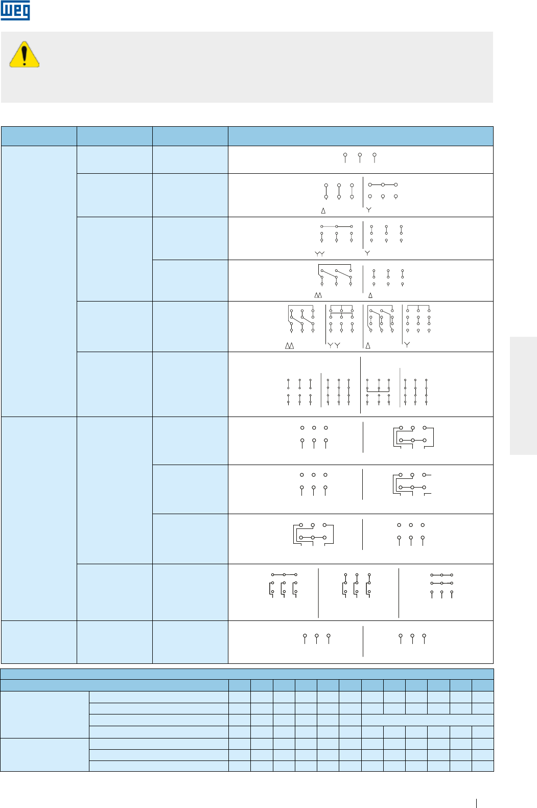
www.weg.net
Elektrische Motoren 197
DEUTSCH
Vor dem Motoranschluss überprüfen, ob die auf dem Leistungsschild angegebene Spannung und
Frequenz des Motors mit dem Drehstromnetz übereinstimmen. Alle elektrischen Verbindungen sind
nach dem auf dem Leistungsschild angegebenen Schaltbild vorzunehmen. Zum Anschluss können
die in der Tabelle 6.2 angegebenen Schaltbilder zugrunde gelegt werden. Es ist sicherzustellen, dass die
Erdung nach einschlägigen Normen vorgenommen wurde, um dadurch Unfälle zu vermeiden.
Konfiguration Klemmenzahl Schaltung Schaltbilder
Eine drehzahl
3 -
L1 L2 L3
31 2
L2L1
1
6
L3
2 3
4 5
L2L1
1
6
L3
2 3
4 5
L3L2L1 L3L2L1
5
2
8
7
1
49
3
68
2
5
7
1
49
3
6
45 64
L1
7
1L3
98 32
L2
7
L1
1
65
3
9
L2 L3
2
8
78 9
L3L2
2L1
3
5
11 12
610
1
4
1
32 L3L2 L1
11
5
8
12 10
6
94
71
32 L3L2 L1
11
5
8
12 10
6
94
71
32 L3L2 L1
11
5
8
12 10
6
94
7
L2
4
L1 L2
1 2
6
L3 L1
3
5
L2L3 L1 L3 L1
RUNSTART
12 10
7 8
PART-WINDING
11
9
START
WYE-DELTA
L2 L3
RUN
3
5
9
11
8
4
2
10
1
6
7
12 1012 11
6 4 5
987 321 3
9
5
11
2
8
1
74
10
6
12
1 2
L2L1
6 4
3
L3 L1 L2
5
L3
LOW SPEED HIGH SPEED
LOW SPEED
L1 L3L2 L3
HIGH SPEED
L1 L2
31 2 1 2 3
LOW SPEED L1 L3L2
L3 HIGH SPEED
L1 L2
6
3
4
1
5
2
1 2 3
4 5 6
LOW SPEED
L1 L3L2 L3
HIGH SPEED
L1 L2
6
3
4
1
5
21 2 3
4 5 6
ONLY FOR
STARTING
6
54
L1 L2 L3
87
1 2 9
3
64 5
HIGH SPEED
L1 L2 L3
8
2
7
19
3
LOW SPEED
5
4
L1 L2
8
7
126
L3
9
3
ONLY FOR
STARTING
654
L1 L2 L3
87
1 2 9
3
64 5
HIGH SPEED
L1 L2 L3
8
2
7
19
3
LOW SPEED
5
4
L1 L2
8
7
126
L3
9
3
64 5 4 5 6
L1 L2 L3
31 2
L2L1
1
6
L3
2 3
4 5
L2L1
1
6
L3
2 3
4 5
L3L2L1 L3L2L1
5
2
8
7
1
49
3
68
2
5
7
1
49
3
6
45 64
L1
7
1L3
98 32
L2
7
L1
1
65
3
9
L2 L3
2
8
78 9
L3L2
2L1
3
5
11 12
610
1
4
1
32 L3L2 L1
11
5
8
12 10
6
94
71
32 L3L2 L1
11
5
8
12 10
6
94
71
32 L3L2 L1
11
5
8
12 10
6
94
7
L2
4
L1 L2
1 2
6
L3 L1
3
5
L2L3 L1 L3 L1
12 10
7 8 11
9
L2 L3
3
5
9
11
8
4
2
10
1
6
7
12 1012 11
6 4 5
987 321 3
9
5
11
2
8
1
74
10
6
12
1 2
L2L1
6 4
3
L3 L1 L2
5
L3
L1 L3L2 L3L1 L2
31 2 1 2 3
L1 L3L2
L3L1 L2
6
3
4
1
5
2
1 2 3
4 5 6
L1 L3L2 L3L1 L2
6
3
4
1
5
21 2 3
4 5 6
654
L1 L2 L3
87
1 2 9
3
64 5
L1 L2 L3
8
2
7
19
3
5
4
L1 L2
8
7
126
L3
9
3654
L1 L2 L3
87
1 2 9
3
64 5
L1 L2 L3
8
2
7
19
3
5
4
L1 L2
8
7
126
L3
9
3
64 5 4 5 6
OPERAÇÃOPARTIDA OPERAÇÃOPARTIDA
PART-WINDING ESTRELA-TRIÂNGULO
MENOR ROTAÇÃO
MENOR ROTAÇÃO
MENOR
ROTAÇÃO
MENOR ROTAÇÃO MAIOR ROTAÇÃO
MAIOR ROTAÇÃO
MAIOR ROTAÇÃO
MENOR ROTAÇÃO MAIOR ROTAÇÃO
MAIOR
ROTAÇÃO SOMENTE
PARTIDA
L1 L2 L3
31 2
L2L1
1
6
L3
2 3
4 5
L2L1
1
6
L3
2 3
4 5
L3L2L1 L3L2L1
5
2
8
7
1
49
3
68
2
5
7
1
49
3
6
45 64
L1
7
1L3
98 32
L2
7
L1
1
65
3
9
L2 L3
2
8
78 9
L3L2
2L1
3
5
11 12
610
1
4
1
32 L3L2 L1
11
5
8
12 10
6
94
71
32 L3L2 L1
11
5
8
12 10
6
94
71
32 L3L2 L1
11
5
8
12 10
6
94
7
L2
4
L1 L2
1 2
6
L3 L1
3
5
L2L3 L1 L3 L1
12 10
7 8 11
9
L2 L3
3
5
9
11
8
4
2
10
1
6
7
12 1012 11
6 4 5
987 321 3
9
5
11
2
8
1
74
10
6
12
1 2
L2L1
6 4
3
L3 L1 L2
5
L3
L1 L3L2 L3L1 L2
31 2 1 2 3
L1 L3L2
L3L1 L2
6
3
4
1
5
2
1 2 3
1 2 3
4 5 6
L1 L3L2 L3L1 L2
6
3
4
1
5
21 2 3
4 5 6
654
L1 L2 L3
87
1 2 9
3
64 5
L1 L2 L3
8
2
7
19
3
5
4
L1 L2
8
7
6
L3
9
654
L1 L2 L3
87
1 2 9
3
64 5
L1 L2 L3
8
2
7
19
3
5
4
L1 L2
8
7
6
L3
9
64 5 4 5 6
PART-WINDING
OPERACIÓNARRANQUE OPERACIÓNARRANQUE
ESTRELLA - TRIÁNGULO
MENOR ROTACIÓN MAYOR ROTACIÓN
MENOR ROTACIÓN
MENOR ROTACIÓN
MENOR ROTACIÓN
MAYOR ROTACIÓN
MAYOR ROTACIÓN
MAYOR ROTACIÓN
SÓLO PARA
ARRANQUE
MAYOR
ROTACIÓN
MENOR
ROTACIÓN
6Δ - Y
L1 L2 L3
31 2
L2L1
1
6
L3
2 3
4 5
L2L1
1
6
L3
2 3
4 5
L3L2L1 L3L2L1
5
2
8
7
1
49
3
68
2
5
7
1
49
3
6
45 64
L1
7
1L3
98 32
L2
7
L1
1
65
3
9
L2 L3
2
8
78 9
L3L2
2L1
3
5
11 12
610
1
4
1
32 L3L2 L1
11
5
8
12 10
6
94
71
32 L3L2 L1
11
5
8
12 10
6
94
71
32 L3L2 L1
11
5
8
12 10
6
94
7
L2
4
L1 L2
1 2
6
L3 L1
3
5
L2L3 L1 L3 L1
RUNSTART
12 10
7 8
PART-WINDING
11
9
START
WYE-DELTA
L2 L3
RUN
3
5
9
11
8
4
2
10
1
6
7
12 1012 11
6 4 5
987 321 3
9
5
11
2
8
1
74
10
6
12
1 2
L2L1
6 4
3
L3 L1 L2
5
L3
LOW SPEED HIGH SPEED
LOW SPEED
L1 L3L2 L3
HIGH SPEED
L1 L2
31 2 1 2 3
LOW SPEED L1 L3L2
L3 HIGH SPEED
L1 L2
6
3
4
1
5
2
1 2 3
4 5 6
LOW SPEED
L1 L3L2 L3
HIGH SPEED
L1 L2
6
3
4
1
5
21 2 3
4 5 6
ONLY FOR
STARTING
6
54
L1 L2 L3
87
1 2 9
3
64 5
HIGH SPEED
L1 L2 L3
8
2
7
19
3
LOW SPEED
5
4
L1 L2
8
7
126
L3
9
3
ONLY FOR
STARTING
654
L1 L2 L3
87
1 2 9
3
64 5
HIGH SPEED
L1 L2 L3
8
2
7
19
3
LOW SPEED
5
4
L1 L2
8
7
126
L3
9
3
64 5 4 5 6
L1 L2 L3
31 2
L2L1
1
6
L3
2 3
4 5
L2L1
1
6
L3
2 3
4 5
L3L2L1 L3L2L1
5
2
8
7
1
49
3
68
2
5
7
1
49
3
6
45 64
L1
7
1L3
98 32
L2
7
L1
1
65
3
9
L2 L3
2
8
78 9
L3L2
2L1
3
5
11 12
610
1
4
1
32 L3L2 L1
11
5
8
12 10
6
94
71
32 L3L2 L1
11
5
8
12 10
6
94
71
32 L3L2 L1
11
5
8
12 10
6
94
7
L2
4
L1 L2
1 2
6
L3 L1
3
5
L2L3 L1 L3 L1
12 10
7 8 11
9
L2 L3
3
5
9
11
8
4
2
10
1
6
7
12 1012 11
6 4 5
987 321 3
9
5
11
2
8
1
74
10
6
12
1 2
L2L1
6 4
3
L3 L1 L2
5
L3
L1 L3L2 L3L1 L2
31 2 1 2 3
L1 L3L2
L3L1 L2
6
3
4
1
5
2
1 2 3
4 5 6
L1 L3L2 L3L1 L2
6
3
4
1
5
21 2 3
4 5 6
654
L1 L2 L3
87
1 2 9
3
64 5
L1 L2 L3
8
2
7
19
3
5
4
L1 L2
8
7
126
L3
9
3654
L1 L2 L3
87
1 2 9
3
64 5
L1 L2 L3
8
2
7
19
3
5
4
L1 L2
8
7
126
L3
9
3
64 5 4 5 6
OPERAÇÃOPARTIDA OPERAÇÃOPARTIDA
PART-WINDING ESTRELA-TRIÂNGULO
MENOR ROTAÇÃO
MENOR ROTAÇÃO
MENOR
ROTAÇÃO
MENOR ROTAÇÃO MAIOR ROTAÇÃO
MAIOR ROTAÇÃO
MAIOR ROTAÇÃO
MENOR ROTAÇÃO MAIOR ROTAÇÃO
MAIOR
ROTAÇÃO SOMENTE
PARTIDA
L1 L2 L3
31 2
L2L1
1
6
L3
2 3
4 5
L2L1
1
6
L3
2 3
4 5
L3L2L1 L3L2L1
5
2
8
7
1
49
3
68
2
5
7
1
49
3
6
45 64
L1
7
1L3
98 32
L2
7
L1
1
65
3
9
L2 L3
2
8
78 9
L3L2
2L1
3
5
11 12
610
1
4
1
32 L3L2 L1
11
5
8
12 10
6
94
71
32 L3L2 L1
11
5
8
12 10
6
94
71
32 L3L2 L1
11
5
8
12 10
6
94
7
L2
4
L1 L2
1 2
6
L3 L1
3
5
L2L3 L1 L3 L1
12 10
7 8 11
9
L2 L3
3
5
9
11
8
4
2
10
1
6
7
12 1012 11
6 4 5
987 321 3
9
5
11
2
8
1
74
10
6
12
1 2
L2L1
6 4
3
L3 L1 L2
5
L3
L1 L3L2 L3L1 L2
31 2 1 2 3
L1 L3L2
L3L1 L2
6
3
4
1
5
2
1 2 3
4 5 6
L1 L3L2 L3L1 L2
6
3
4
1
5
21 2 3
4 5 6
64 5 4 5 6
PART-WINDING
OPERACIÓNARRANQUE OPERACIÓNARRANQUE
ESTRELLA - TRIÁNGULO
MENOR ROTACIÓN MAYOR ROTACIÓN
MENOR ROTACIÓN
MENOR ROTACIÓN
MENOR ROTACIÓN
MAYOR ROTACIÓN
MAYOR ROTACIÓN
MAYOR ROTACIÓN
6
5
4
L1 L2 L3
87 9
13 2
6
5
4
L1 L2 L3
87 9
SÓLO PARA
ARRANQUE
64 5
L1 L2 L3
8
1
7
39
2
64 5
L1 L2 L3
8
79
MAYOR
ROTACIÓN
5
4
L1 L2
8
716
L3
9
5
4
L1 L2
8
72
6
L3
9
3
MENOR
ROTACIÓN
9
YY - Y
L1 L2 L3
31 2
L2L1
1
6
L3
2 3
4 5
L2L1
1
6
L3
2 3
4 5
L3L2L1 L3L2L1
5
2
8
7
1
49
3
68
2
5
7
1
49
3
6
45 64
L1
7
1L3
98 32
L2
7
L1
1
65
3
9
L2 L3
2
8
78 9
L3L2
2L1
3
5
11 12
610
1
4
1
32 L3L2 L1
11
5
8
12 10
6
94
71
32 L3L2 L1
11
5
8
12 10
6
94
71
32 L3L2 L1
11
5
8
12 10
6
94
7
L2
4
L1 L2
1 2
6
L3 L1
3
5
L2L3 L1 L3 L1
RUNSTART
12 10
7 8
PART-WINDING
11
9
START
WYE-DELTA
L2 L3
RUN
3
5
9
11
8
4
2
10
1
6
7
12 1012 11
6 4 5
987 321 3
9
5
11
2
8
1
74
10
6
12
1 2
L2L1
6 4
3
L3 L1 L2
5
L3
LOW SPEED HIGH SPEED
LOW SPEED
L1 L3L2 L3
HIGH SPEED
L1 L2
31 2 1 2 3
LOW SPEED L1 L3L2
L3 HIGH SPEED
L1 L2
6
3
4
1
5
2
1 2 3
4 5 6
LOW SPEED
L1 L3L2 L3
HIGH SPEED
L1 L2
6
3
4
1
5
21 2 3
4 5 6
ONLY FOR
STARTING
6
54
L1 L2 L3
87
1 2 9
3
64 5
HIGH SPEED
L1 L2 L3
8
2
7
19
3
LOW SPEED
5
4
L1 L2
8
7
126
L3
9
3
ONLY FOR
STARTING
654
L1 L2 L3
87
1 2 9
3
64 5
HIGH SPEED
L1 L2 L3
8
2
7
19
3
LOW SPEED
5
4
L1 L2
8
7
126
L3
9
3
64 5 4 5 6
L1 L2 L3
31 2
L2L1
1
6
L3
2 3
4 5
L2L1
1
6
L3
2 3
4 5
L3L2L1 L3L2L1
5
2
8
7
1
49
3
68
2
5
7
1
49
3
6
45 64
L1
7
1L3
98 32
L2
7
L1
1
65
3
9
L2 L3
2
8
78 9
L3L2
2L1
3
5
11 12
610
1
4
1
32 L3L2 L1
11
5
8
12 10
6
94
71
32 L3L2 L1
11
5
8
12 10
6
94
71
32 L3L2 L1
11
5
8
12 10
6
94
7
L2
4
L1 L2
1 2
6
L3 L1
3
5
L2L3 L1 L3 L1
12 10
7 8 11
9
L2 L3
3
5
9
11
8
4
2
10
1
6
7
12 1012 11
6 4 5
987 321 3
9
5
11
2
8
1
74
10
6
12
1 2
L2L1
6 4
3
L3 L1 L2
5
L3
L1 L3L2 L3L1 L2
31 2 1 2 3
L1 L3L2
L3L1 L2
6
3
4
1
5
2
1 2 3
4 5 6
L1 L3L2 L3L1 L2
6
3
4
1
5
21 2 3
4 5 6
654
L1 L2 L3
87
1 2 9
3
64 5
L1 L2 L3
8
2
7
19
3
5
4
L1 L2
8
7
126
L3
9
3654
L1 L2 L3
87
1 2 9
3
64 5
L1 L2 L3
8
2
7
19
3
5
4
L1 L2
8
7
126
L3
9
3
64 5 4 5 6
OPERAÇÃOPARTIDA OPERAÇÃOPARTIDA
PART-WINDING ESTRELA-TRIÂNGULO
MENOR ROTAÇÃO
MENOR ROTAÇÃO
MENOR
ROTAÇÃO
MENOR ROTAÇÃO MAIOR ROTAÇÃO
MAIOR ROTAÇÃO
MAIOR ROTAÇÃO
MENOR ROTAÇÃO MAIOR ROTAÇÃO
MAIOR
ROTAÇÃO SOMENTE
PARTIDA
L1 L2 L3
31 2
L2L1
1
6
L3
2 3
4 5
L2L1
1
6
L3
2 3
4 5
L3L2L1 L3L2L1
5
2
8
7
1
49
3
68
2
5
7
1
49
3
6
45 64
L1
7
1L3
98 32
L2
7
L1
1
65
3
9
L2 L3
2
8
78 9
L3L2
2L1
3
5
11 12
610
1
4
1
32 L3L2 L1
11
5
8
12 10
6
94
71
32 L3L2 L1
11
5
8
12 10
6
94
71
32 L3L2 L1
11
5
8
12 10
6
94
7
L2
4
L1 L2
1 2
6
L3 L1
3
5
L2L3 L1 L3 L1
12 10
7 8 11
9
L2 L3
3
5
9
11
8
4
2
10
1
6
7
12 1012 11
6 4 5
987 321 3
9
5
11
2
8
1
74
10
6
12
1 2
L2L1
6 4
3
L3 L1 L2
5
L3
L1 L3L2 L3L1 L2
31 2 1 2 3
L1 L3L2
L3L1 L2
6
3
4
1
5
2
1 2 3
4 5 6
L1 L3L2 L3L1 L2
6
3
4
1
5
21 2 3
4 5 6
64 5 4 5 6
PART-WINDING
OPERACIÓNARRANQUE OPERACIÓNARRANQUE
ESTRELLA - TRIÁNGULO
MENOR ROTACIÓN MAYOR ROTACIÓN
MENOR ROTACIÓN
MENOR ROTACIÓN
MENOR ROTACIÓN
MAYOR ROTACIÓN
MAYOR ROTACIÓN
MAYOR ROTACIÓN
6
5
4
L1 L2 L3
87 9
13 2
6
5
4
L1 L2 L3
87 9
SÓLO PARA
ARRANQUE
64 5
L1 L2 L3
8
1
7
39
2
64 5
L1 L2 L3
8
79
MAYOR
ROTACIÓN
5
4
L1 L2
8
716
L3
9
5
4
L1 L2
8
72
6
L3
9
3
MENOR
ROTACIÓN
ΔΔ - Δ
L1 L2 L3
31 2
L2L1
1
6
L3
2 3
4 5
L2L1
1
6
L3
2 3
4 5
L3L2L1 L3L2L1
5
2
8
7
1
49
3
68
2
5
7
1
49
3
6
45 64
L1
7
1L3
98 32
L2
7
L1
1
65
3
9
L2 L3
2
8
78 9
L3L2
2L1
3
5
11 12
610
1
4
1
32 L3L2 L1
11
5
8
12 10
6
94
71
32 L3L2 L1
11
5
8
12 10
6
94
71
32 L3L2 L1
11
5
8
12 10
6
94
7
L2
4
L1 L2
1 2
6
L3 L1
3
5
L2L3 L1 L3 L1
RUNSTART
12 10
7 8
PART-WINDING
11
9
START
WYE-DELTA
L2 L3
RUN
3
5
9
11
8
4
2
10
1
6
7
12 1012 11
6 4 5
987 321 3
9
5
11
2
8
1
74
10
6
12
1 2
L2L1
6 4
3
L3 L1 L2
5
L3
LOW SPEED HIGH SPEED
LOW SPEED
L1 L3L2 L3
HIGH SPEED
L1 L2
31 2 1 2 3
LOW SPEED L1 L3L2
L3 HIGH SPEED
L1 L2
6
3
4
1
5
2
1 2 3
4 5 6
LOW SPEED
L1 L3L2 L3
HIGH SPEED
L1 L2
6
3
4
1
5
21 2 3
4 5 6
ONLY FOR
STARTING
6
54
L1 L2 L3
87
1 2 9
3
64 5
HIGH SPEED
L1 L2 L3
8
2
7
19
3
LOW SPEED
5
4
L1 L2
8
7
126
L3
9
3
ONLY FOR
STARTING
654
L1 L2 L3
87
1 2 9
3
64 5
HIGH SPEED
L1 L2 L3
8
2
7
19
3
LOW SPEED
5
4
L1 L2
8
7
126
L3
9
3
64 5 4 5 6
L1 L2 L3
31 2
L2L1
1
6
L3
2 3
4 5
L2L1
1
6
L3
2 3
4 5
L3L2L1 L3L2L1
5
2
8
7
1
49
3
68
2
5
7
1
49
3
6
45 64
L1
7
1L3
98 32
L2
7
L1
1
65
3
9
L2 L3
2
8
78 9
L3L2
2L1
3
5
11 12
610
1
4
1
32 L3L2 L1
11
5
8
12 10
6
94
71
32 L3L2 L1
11
5
8
12 10
6
94
71
32 L3L2 L1
11
5
8
12 10
6
94
7
L2
4
L1 L2
1 2
6
L3 L1
3
5
L2L3 L1 L3 L1
12 10
7 8 11
9
L2 L3
3
5
9
11
8
4
2
10
1
6
7
12 1012 11
6 4 5
987 321 3
9
5
11
2
8
1
74
10
6
12
1 2
L2L1
6 4
3
L3 L1 L2
5
L3
L1 L3L2 L3L1 L2
31 2 1 2 3
L1 L3L2
L3L1 L2
6
3
4
1
5
2
1 2 3
4 5 6
L1 L3L2 L3L1 L2
6
3
4
1
5
21 2 3
4 5 6
654
L1 L2 L3
87
1 2 9
3
64 5
L1 L2 L3
8
2
7
19
3
5
4
L1 L2
8
7
126
L3
9
3654
L1 L2 L3
87
1 2 9
3
64 5
L1 L2 L3
8
2
7
19
3
5
4
L1 L2
8
7
126
L3
9
3
64 5 4 5 6
OPERAÇÃOPARTIDA OPERAÇÃOPARTIDA
PART-WINDING ESTRELA-TRIÂNGULO
MENOR ROTAÇÃO
MENOR ROTAÇÃO
MENOR
ROTAÇÃO
MENOR ROTAÇÃO MAIOR ROTAÇÃO
MAIOR ROTAÇÃO
MAIOR ROTAÇÃO
MENOR ROTAÇÃO MAIOR ROTAÇÃO
MAIOR
ROTAÇÃO SOMENTE
PARTIDA
L1 L2 L3
31 2
L2L1
1
6
L3
2 3
4 5
L2L1
1
6
L3
2 3
4 5
L3L2L1 L3L2L1
5
2
8
7
1
49
3
68
2
5
7
1
49
3
6
45 64
L1
7
1L3
98 32
L2
7
L1
1
65
3
9
L2 L3
2
8
78 9
L3L2
2L1
3
5
11 12
610
1
4
1
32 L3L2 L1
11
5
8
12 10
6
94
71
32 L3L2 L1
11
5
8
12 10
6
94
71
32 L3L2 L1
11
5
8
12 10
6
94
7
L2
4
L1 L2
1 2
6
L3 L1
3
5
L2L3 L1 L3 L1
12 10
7 8 11
9
L2 L3
3
5
9
11
8
4
2
10
1
6
7
12 1012 11
6 4 5
987 321 3
9
5
11
2
8
1
74
10
6
12
1 2
L2L1
6 4
3
L3 L1 L2
5
L3
L1 L3L2 L3L1 L2
31 2 1 2 3
L1 L3L2
L3L1 L2
6
3
4
1
5
2
1 2 3
4 5 6
L1 L3L2 L3L1 L2
6
3
4
1
5
21 2 3
4 5 6
64 5 4 5 6
PART-WINDING
OPERACIÓNARRANQUE OPERACIÓNARRANQUE
ESTRELLA - TRIÁNGULO
MENOR ROTACIÓN MAYOR ROTACIÓN
MENOR ROTACIÓN
MENOR ROTACIÓN
MENOR ROTACIÓN
MAYOR ROTACIÓN
MAYOR ROTACIÓN
MAYOR ROTACIÓN
6
5
4
L1 L2 L3
87 9
13 2
6
5
4
L1 L2 L3
87 9
SÓLO PARA
ARRANQUE
64 5
L1 L2 L3
8
1
7
39
2
64 5
L1 L2 L3
8
79
MAYOR
ROTACIÓN
5
4
L1 L2
8
716
L3
9
5
4
L1 L2
8
72
6
L3
9
3
MENOR
ROTACIÓN
ΔΔ - YY - Δ - Y
L1 L2 L3
31 2
L2L1
1
6
L3
2 3
4 5
L2L1
1
6
L3
2 3
4 5
L3L2L1 L3L2L1
5
2
8
7
1
49
3
68
2
5
7
1
49
3
6
45 64
L1
7
1L3
98 32
L2
7
L1
1
65
3
9
L2 L3
2
8
78 9
L3L2
2L1
3
5
11 12
610
1
4
1
32 L3L2 L1
11
5
8
12 10
6
94
71
32 L3L2 L1
11
5
8
12 10
6
94
71
32 L3L2 L1
11
5
8
12 10
6
94
7
L2
4
L1 L2
1 2
6
L3 L1
3
5
L2L3 L1 L3 L1
RUNSTART
12 10
7 8
PART-WINDING
11
9
START
WYE-DELTA
L2 L3
RUN
3
5
9
11
8
4
2
10
1
6
7
12 1012 11
6 4 5
987 321 3
9
5
11
2
8
1
74
10
6
12
1 2
L2L1
6 4
3
L3 L1 L2
5
L3
LOW SPEED HIGH SPEED
LOW SPEED
L1 L3L2 L3
HIGH SPEED
L1 L2
31 2 1 2 3
LOW SPEED L1 L3L2
L3 HIGH SPEED
L1 L2
6
3
4
1
5
2
1 2 3
4 5 6
LOW SPEED
L1 L3L2 L3
HIGH SPEED
L1 L2
6
3
4
1
5
21 2 3
4 5 6
ONLY FOR
STARTING
6
54
L1 L2 L3
87
1 2 9
3
64 5
HIGH SPEED
L1 L2 L3
8
2
7
19
3
LOW SPEED
5
4
L1 L2
8
7
126
L3
9
3
ONLY FOR
STARTING
654
L1 L2 L3
87
1 2 9
3
64 5
HIGH SPEED
L1 L2 L3
8
2
7
19
3
LOW SPEED
5
4
L1 L2
8
7
126
L3
9
3
64 5 4 5 6
L1 L2 L3
31 2
L2L1
1
6
L3
2 3
4 5
L2L1
1
6
L3
2 3
4 5
L3L2L1 L3L2L1
5
2
8
7
1
49
3
68
2
5
7
1
49
3
6
45 64
L1
7
1L3
98 32
L2
7
L1
1
65
3
9
L2 L3
2
8
78 9
L3L2
2L1
3
5
11 12
610
1
4
1
32 L3L2 L1
11
5
8
12 10
6
94
71
32 L3L2 L1
11
5
8
12 10
6
94
71
32 L3L2 L1
11
5
8
12 10
6
94
7
L2
4
L1 L2
1 2
6
L3 L1
3
5
L2L3 L1 L3 L1
12 10
7 8 11
9
L2 L3
3
5
9
11
8
4
2
10
1
6
7
12 1012 11
6 4 5
987 321 3
9
5
11
2
8
1
74
10
6
12
1 2
L2L1
6 4
3
L3 L1 L2
5
L3
L1 L3L2 L3L1 L2
31 2 1 2 3
L1 L3L2
L3L1 L2
6
3
4
1
5
2
1 2 3
4 5 6
L1 L3L2 L3L1 L2
6
3
4
1
5
21 2 3
4 5 6
654
L1 L2 L3
87
1 2 9
3
64 5
L1 L2 L3
8
2
7
19
3
5
4
L1 L2
8
7
126
L3
9
3654
L1 L2 L3
87
1 2 9
3
64 5
L1 L2 L3
8
2
7
19
3
5
4
L1 L2
8
7
126
L3
9
3
64 5 4 5 6
OPERAÇÃOPARTIDA OPERAÇÃOPARTIDA
PART-WINDING ESTRELA-TRIÂNGULO
MENOR ROTAÇÃO
MENOR ROTAÇÃO
MENOR
ROTAÇÃO
MENOR ROTAÇÃO MAIOR ROTAÇÃO
MAIOR ROTAÇÃO
MAIOR ROTAÇÃO
MENOR ROTAÇÃO MAIOR ROTAÇÃO
MAIOR
ROTAÇÃO SOMENTE
PARTIDA
L1 L2 L3
31 2
L2L1
1
6
L3
2 3
4 5
L2L1
1
6
L3
2 3
4 5
L3L2L1 L3L2L1
5
2
8
7
1
49
3
68
2
5
7
1
49
3
6
45 64
L1
7
1L3
98 32
L2
7
L1
1
65
3
9
L2 L3
2
8
78 9
L3L2
2L1
3
5
11 12
610
1
4
1
32 L3L2 L1
11
5
8
12 10
6
94
71
32 L3L2 L1
11
5
8
12 10
6
94
71
32 L3L2 L1
11
5
8
12 10
6
94
7
L2
4
L1 L2
1 2
6
L3 L1
3
5
L2L3 L1 L3 L1
12 10
7 8 11
9
L2 L3
3
5
9
11
8
4
2
10
1
6
7
12 1012 11
6 4 5
987 321 3
9
5
11
2
8
1
74
10
6
12
1 2
L2L1
6 4
3
L3 L1 L2
5
L3
L1 L3L2 L3L1 L2
31 2 1 2 3
L1 L3L2
L3L1 L2
6
3
4
1
5
2
1 2 3
4 5 6
L1 L3L2 L3L1 L2
6
3
4
1
5
21 2 3
4 5 6
64 5 4 5 6
PART-WINDING
OPERACIÓNARRANQUE OPERACIÓNARRANQUE
ESTRELLA - TRIÁNGULO
MENOR ROTACIÓN MAYOR ROTACIÓN
MENOR ROTACIÓN
MENOR ROTACIÓN
MENOR ROTACIÓN
MAYOR ROTACIÓN
MAYOR ROTACIÓN
MAYOR ROTACIÓN
6
5
4
L1 L2 L3
87 9
13 2
6
5
4
L1 L2 L3
87 9
SÓLO PARA
ARRANQUE
64 5
L1 L2 L3
8
1
7
39
2
64 5
L1 L2 L3
8
79
MAYOR
ROTACIÓN
5
4
L1 L2
8
716
L3
9
5
4
L1 L2
8
72
6
L3
9
3
MENOR
ROTACIÓN
12
Δ - PWS
Anlauf Über
Getrennte Wicklung
(Part-Winding)
L1 L2 L3
31 2
L2L1
1
6
L3
2 3
4 5
L2L1
1
6
L3
2 3
4 5
L3L2L1 L3L2L1
5
2
8
7
1
49
3
68
2
5
7
1
49
3
6
45 64
L1
7
1L3
98 32
L2
7
L1
1
65
3
9
L2 L3
2
8
78 9
L3L2
2L1
3
5
11 12
610
1
4
1
32 L3L2 L1
11
5
8
12 10
6
94
71
32 L3L2 L1
11
5
8
12 10
6
94
71
32 L3L2 L1
11
5
8
12 10
6
94
7
L2
4
L1 L2
1 2
6
L3 L1
3
5
L2L3 L1 L3 L1
RUNSTART
12 10
7 8
PART-WINDING
11
9
START
WYE-DELTA
L2 L3
RUN
3
5
9
11
8
4
2
10
1
6
7
12 1012 11
6 4 5
987 321 3
9
5
11
2
8
1
74
10
6
12
1 2
L2L1
6 4
3
L3 L1 L2
5
L3
LOW SPEED HIGH SPEED
LOW SPEED
L1 L3L2 L3
HIGH SPEED
L1 L2
31 2 1 2 3
LOW SPEED L1 L3L2
L3 HIGH SPEED
L1 L2
6
3
4
1
5
2
1 2 3
4 5 6
LOW SPEED
L1 L3L2 L3
HIGH SPEED
L1 L2
6
3
4
1
5
21 2 3
4 5 6
ONLY FOR
STARTING
6
54
L1 L2 L3
87
1 2 9
3
64 5
HIGH SPEED
L1 L2 L3
8
2
7
19
3
LOW SPEED
5
4
L1 L2
8
7
126
L3
9
3
ONLY FOR
STARTING
654
L1 L2 L3
87
1 2 9
3
64 5
HIGH SPEED
L1 L2 L3
8
2
7
19
3
LOW SPEED
5
4
L1 L2
8
7
126
L3
9
3
64 5 4 5 6
L1 L2 L3
31 2
L2L1
1
6
L3
2 3
4 5
L2L1
1
6
L3
2 3
4 5
L3L2L1 L3L2L1
5
2
8
7
1
49
3
68
2
5
7
1
49
3
6
45 64
L1
7
1L3
98 32
L2
7
L1
1
65
3
9
L2 L3
2
8
78 9
L3L2
2L1
3
5
11 12
610
1
4
1
32 L3L2 L1
11
5
8
12 10
6
94
71
32 L3L2 L1
11
5
8
12 10
6
94
71
32 L3L2 L1
11
5
8
12 10
6
94
7
L2
4
L1 L2
1 2
6
L3 L1
3
5
L2L3 L1 L3 L1
12 10
7 8 11
9
L2 L3
3
5
9
11
8
4
2
10
1
6
7
12 1012 11
6 4 5
987 321 3
9
5
11
2
8
1
74
10
6
12
1 2
L2L1
6 4
3
L3 L1 L2
5
L3
L1 L3L2 L3L1 L2
31 2 1 2 3
L1 L3L2
L3L1 L2
6
3
4
1
5
2
1 2 3
4 5 6
L1 L3L2 L3L1 L2
6
3
4
1
5
21 2 3
4 5 6
654
L1 L2 L3
87
1 2 9
3
64 5
L1 L2 L3
8
2
7
19
3
5
4
L1 L2
8
7
126
L3
9
3654
L1 L2 L3
87
1 2 9
3
64 5
L1 L2 L3
8
2
7
19
3
5
4
L1 L2
8
7
126
L3
9
3
64 5 4 5 6
OPERAÇÃOPARTIDA OPERAÇÃOPARTIDA
PART-WINDING ESTRELA-TRIÂNGULO
MENOR ROTAÇÃO
MENOR ROTAÇÃO
MENOR
ROTAÇÃO
MENOR ROTAÇÃO MAIOR ROTAÇÃO
MAIOR ROTAÇÃO
MAIOR ROTAÇÃO
MENOR ROTAÇÃO MAIOR ROTAÇÃO
MAIOR
ROTAÇÃO SOMENTE
PARTIDA
L1 L2 L3
31 2
L2L1
1
6
L3
2 3
4 5
L2L1
1
6
L3
2 3
4 5
L3L2L1 L3L2L1
5
2
8
7
1
49
3
68
2
5
7
1
49
3
6
45 64
L1
7
1L3
98 32
L2
7
L1
1
65
3
9
L2 L3
2
8
78 9
L3L2
2L1
3
5
11 12
610
1
4
1
32 L3L2 L1
11
5
8
12 10
6
94
71
32 L3L2 L1
11
5
8
12 10
6
94
71
32 L3L2 L1
11
5
8
12 10
6
94
7
L2
4
L1 L2
1 2
6
L3 L1
3
5
L2L3 L1 L3 L1
12 10
7 8 11
9
L2 L3
3
5
9
11
8
4
2
10
1
6
7
12 1012 11
6 4 5
987 321 3
9
5
11
2
8
1
74
10
6
12
1 2
L2L1
6 4
3
L3 L1 L2
5
L3
L1 L3L2 L3L1 L2
31 2 1 2 3
L1 L3L2
L3L1 L2
6
3
4
1
5
2
1 2 3
4 5 6
L1 L3L2 L3L1 L2
6
3
4
1
5
21 2 3
4 5 6
64 5 4 5 6
PART-WINDING
OPERACIÓNARRANQUE OPERACIÓNARRANQUE
ESTRELLA - TRIÁNGULO
MENOR ROTACIÓN MAYOR ROTACIÓN
MENOR ROTACIÓN
MENOR ROTACIÓN
MENOR ROTACIÓN
MAYOR ROTACIÓN
MAYOR ROTACIÓN
MAYOR ROTACIÓN
6
5
4
L1 L2 L3
87 9
13 2
6
5
4
L1 L2 L3
87 9
SÓLO PARA
ARRANQUE
64 5
L1 L2 L3
8
1
7
39
2
64 5
L1 L2 L3
8
79
MAYOR
ROTACIÓN
5
4
L1 L2
8
716
L3
9
5
4
L1 L2
8
72
6
L3
9
3
MENOR
ROTACIÓN
Zwei oder mehrere
Drehzahlen in
Dahlander- und/
oder getrennte
Wicklungen
6
Y - YY
Veränder-Bares
Dremoment
L1 L2 L3
31 2
L2L1
1
6
L3
2 3
4 5
L2L1
1
6
L3
2 3
4 5
L3L2L1 L3L2L1
5
2
8
7
1
49
3
68
2
5
7
1
49
3
6
45 64
L1
7
1L3
98 32
L2
7
L1
1
65
3
9
L2 L3
2
8
78 9
L3L2
2L1
3
5
11 12
610
1
4
1
32 L3L2 L1
11
5
8
12 10
6
94
71
32 L3L2 L1
11
5
8
12 10
6
94
71
32 L3L2 L1
11
5
8
12 10
6
94
7
L2
4
L1 L2
1 2
6
L3 L1
3
5
L2L3 L1 L3 L1
RUNSTART
12 10
7 8
PART-WINDING
11
9
START
WYE-DELTA
L2 L3
RUN
3
5
9
11
8
4
2
10
1
6
7
12 1012 11
6 4 5
987 321 3
9
5
11
2
8
1
74
10
6
12
1 2
L2L1
6 4
3
L3 L1 L2
5
L3
LOW SPEED HIGH SPEED
LOW SPEED
L1 L3L2 L3
HIGH SPEED
L1 L2
31 2 1 2 3
LOW SPEED L1 L3L2
L3 HIGH SPEED
L1 L2
6
3
4
1
5
2
1 2 3
4 5 6
LOW SPEED
L1 L3L2 L3
HIGH SPEED
L1 L2
6
3
4
1
5
21 2 3
4 5 6
ONLY FOR
STARTING
6
54
L1 L2 L3
87
1 2 9
3
64 5
HIGH SPEED
L1 L2 L3
8
2
7
19
3
LOW SPEED
5
4
L1 L2
8
7
126
L3
9
3
ONLY FOR
STARTING
654
L1 L2 L3
87
1 2 9
3
64 5
HIGH SPEED
L1 L2 L3
8
2
7
19
3
LOW SPEED
5
4
L1 L2
8
7
126
L3
9
3
64 5 4 5 6
L1 L2 L3
31 2
L2L1
1
6
L3
2 3
4 5
L2L1
1
6
L3
2 3
4 5
L3L2L1 L3L2L1
5
2
8
7
1
49
3
68
2
5
7
1
49
3
6
45 64
L1
7
1L3
98 32
L2
7
L1
1
65
3
9
L2 L3
2
8
78 9
L3L2
2L1
3
5
11 12
610
1
4
1
32 L3L2 L1
11
5
8
12 10
6
94
71
32 L3L2 L1
11
5
8
12 10
6
94
71
32 L3L2 L1
11
5
8
12 10
6
94
7
L2
4
L1 L2
1 2
6
L3 L1
3
5
L2L3 L1 L3 L1
12 10
7 8 11
9
L2 L3
3
5
9
11
8
4
2
10
1
6
7
12 1012 11
6 4 5
987 321 3
9
5
11
2
8
1
74
10
6
12
1 2
L2L1
6 4
3
L3 L1 L2
5
L3
L1 L3L2 L3L1 L2
31 2 1 2 3
L1 L3L2
L3L1 L2
6
3
4
1
5
2
1 2 3
4 5 6
L1 L3L2 L3L1 L2
6
3
4
1
5
21 2 3
4 5 6
654
L1 L2 L3
87
1 2 9
3
64 5
L1 L2 L3
8
2
7
19
3
5
4
L1 L2
8
7
126
L3
9
3654
L1 L2 L3
87
1 2 9
3
64 5
L1 L2 L3
8
2
7
19
3
5
4
L1 L2
8
7
126
L3
9
3
64 5 4 5 6
OPERAÇÃOPARTIDA OPERAÇÃOPARTIDA
PART-WINDING ESTRELA-TRIÂNGULO
MENOR ROTAÇÃO
MENOR ROTAÇÃO
MENOR
ROTAÇÃO
MENOR ROTAÇÃO MAIOR ROTAÇÃO
MAIOR ROTAÇÃO
MAIOR ROTAÇÃO
MENOR ROTAÇÃO MAIOR ROTAÇÃO
MAIOR
ROTAÇÃO SOMENTE
PARTIDA
L1 L2 L3
31 2
L2L1
1
6
L3
2 3
4 5
L2L1
1
6
L3
2 3
4 5
L3L2L1 L3L2L1
5
2
8
7
1
49
3
68
2
5
7
1
49
3
6
45 64
L1
7
1L3
98 32
L2
7
L1
1
65
3
9
L2 L3
2
8
78 9
L3L2
2L1
3
5
11 12
610
1
4
1
32 L3L2 L1
11
5
8
12 10
6
94
71
32 L3L2 L1
11
5
8
12 10
6
94
71
32 L3L2 L1
11
5
8
12 10
6
94
7
L2
4
L1 L2
1 2
6
L3 L1
3
5
L2L3 L1 L3 L1
12 10
7 8 11
9
L2 L3
3
5
9
11
8
4
2
10
1
6
7
12 1012 11
6 4 5
987 321 3
9
5
11
2
8
1
74
10
6
12
1 2
L2L1
6 4
3
L3 L1 L2
5
L3
L1 L3L2 L3L1 L2
31 2 1 2 3
L1 L3L2
L3L1 L2
6
3
4
1
5
2
1 2 3
4 5 6
L1 L3L2 L3L1 L2
6
3
4
1
5
21 2 3
4 5 6
64 5 4 5 6
PART-WINDING
OPERACIÓNARRANQUE OPERACIÓNARRANQUE
ESTRELLA - TRIÁNGULO
MENOR ROTACIÓN MAYOR ROTACIÓN
MENOR ROTACIÓN
MENOR ROTACIÓN
MENOR ROTACIÓN
MAYOR ROTACIÓN
MAYOR ROTACIÓN
MAYOR ROTACIÓN
6
5
4
L1 L2 L3
87 9
13 2
6
5
4
L1 L2 L3
87 9
SÓLO PARA
ARRANQUE
64 5
L1 L2 L3
8
1
7
39
2
64 5
L1 L2 L3
8
79
MAYOR
ROTACIÓN
5
4
L1 L2
8
716
L3
9
5
4
L1 L2
8
72
6
L3
9
3
MENOR
ROTACIÓN
Δ - YY
Konstantes
Drehmoment
L1 L2 L3
31 2
L2L1
1
6
L3
2 3
4 5
L2L1
1
6
L3
2 3
4 5
L3L2L1 L3L2L1
5
2
8
7
1
49
3
68
2
5
7
1
49
3
6
45 64
L1
7
1L3
98 32
L2
7
L1
1
65
3
9
L2 L3
2
8
78 9
L3L2
2L1
3
5
11 12
610
1
4
1
32 L3L2 L1
11
5
8
12 10
6
94
71
32 L3L2 L1
11
5
8
12 10
6
94
71
32 L3L2 L1
11
5
8
12 10
6
94
7
L2
4
L1 L2
1 2
6
L3 L1
3
5
L2L3 L1 L3 L1
RUNSTART
12 10
7 8
PART-WINDING
11
9
START
WYE-DELTA
L2 L3
RUN
3
5
9
11
8
4
2
10
1
6
7
12 1012 11
6 4 5
987 321 3
9
5
11
2
8
1
74
10
6
12
1 2
L2L1
6 4
3
L3 L1 L2
5
L3
LOW SPEED HIGH SPEED
LOW SPEED
L1 L3L2 L3
HIGH SPEED
L1 L2
31 2 1 2 3
LOW SPEED L1 L3L2
L3 HIGH SPEED
L1 L2
6
3
4
1
5
2
1 2 3
4 5 6
LOW SPEED
L1 L3L2 L3
HIGH SPEED
L1 L2
6
3
4
1
5
21 2 3
4 5 6
ONLY FOR
STARTING
6
54
L1 L2 L3
87
1 2 9
3
64 5
HIGH SPEED
L1 L2 L3
8
2
7
19
3
LOW SPEED
5
4
L1 L2
8
7
126
L3
9
3
ONLY FOR
STARTING
654
L1 L2 L3
87
1 2 9
3
64 5
HIGH SPEED
L1 L2 L3
8
2
7
19
3
LOW SPEED
5
4
L1 L2
8
7
126
L3
9
3
64 5 4 5 6
L1 L2 L3
31 2
L2L1
1
6
L3
2 3
4 5
L2L1
1
6
L3
2 3
4 5
L3L2L1 L3L2L1
5
2
8
7
1
49
3
68
2
5
7
1
49
3
6
45 64
L1
7
1L3
98 32
L2
7
L1
1
65
3
9
L2 L3
2
8
78 9
L3L2
2L1
3
5
11 12
610
1
4
1
32 L3L2 L1
11
5
8
12 10
6
94
71
32 L3L2 L1
11
5
8
12 10
6
94
71
32 L3L2 L1
11
5
8
12 10
6
94
7
L2
4
L1 L2
1 2
6
L3 L1
3
5
L2L3 L1 L3 L1
12 10
7 8 11
9
L2 L3
3
5
9
11
8
4
2
10
1
6
7
12 1012 11
6 4 5
987 321 3
9
5
11
2
8
1
74
10
6
12
1 2
L2L1
6 4
3
L3 L1 L2
5
L3
L1 L3L2 L3L1 L2
31 2 1 2 3
L1 L3L2
L3L1 L2
6
3
4
1
5
2
1 2 3
4 5 6
L1 L3L2 L3L1 L2
6
3
4
1
5
21 2 3
4 5 6
654
L1 L2 L3
87
1 2 9
3
64 5
L1 L2 L3
8
2
7
19
3
5
4
L1 L2
8
7
126
L3
9
3654
L1 L2 L3
87
1 2 9
3
64 5
L1 L2 L3
8
2
7
19
3
5
4
L1 L2
8
7
126
L3
9
3
64 5 4 5 6
OPERAÇÃOPARTIDA OPERAÇÃOPARTIDA
PART-WINDING ESTRELA-TRIÂNGULO
MENOR ROT
AÇÃO
MENOR ROTAÇÃO
MENOR
ROTAÇÃO
MENOR ROTAÇÃO MAIOR ROTAÇÃO
MAIOR ROT
AÇÃO
MAIOR ROTAÇÃO
MENOR ROTAÇÃO MAIOR ROTAÇÃO
MAIOR
ROTAÇÃO SOMENTE
PARTIDA
L1 L2 L3
31 2
L2L1
1
6
L3
2 3
4 5
L2L1
1
6
L3
2 3
4 5
L3L2L1 L3L2L1
5
2
8
7
1
49
3
68
2
5
7
1
49
3
6
45 64
L1
7
1L3
98 32
L2
7
L1
1
65
3
9
L2 L3
2
8
78 9
L3L2
2L1
3
5
11 12
610
1
4
1
32 L3L2 L1
11
5
8
12 10
6
94
71
32 L3L2 L1
11
5
8
12 10
6
94
71
32 L3L2 L1
11
5
8
12 10
6
94
7
L2
4
L1 L2
1 2
6
L3 L1
3
5
L2L3 L1 L3 L1
12 10
7 8 11
9
L2 L3
3
5
9
11
8
4
2
10
1
6
7
12 1012 11
6 4 5
987 321 3
9
5
11
2
8
1
74
10
6
12
1 2
L2L1
6 4
3
L3 L1 L2
5
L3
L1 L3L2 L3L1 L2
31 2 1 2 3
L1 L3L2
L3L1 L2
6
3
4
1
5
2
1 2 3
4 5 6
L1 L3L2 L3L1 L2
6
3
4
1
5
21 2 3
4 5 6
64 5 4 5 6
PART-WINDING
OPERACIÓNARRANQUE OPERACIÓNARRANQUE
ESTRELLA - TRIÁNGULO
MENOR ROTACIÓN MAYOR ROTACIÓN
MENOR ROTACIÓN
MENOR ROTACIÓN
MENOR ROTACIÓN
MAYOR ROTACIÓN
MAYOR ROTACIÓN
MAYOR ROTACIÓN
6
5
4
L1 L2 L3
87 9
13 2
6
5
4
L1 L2 L3
87 9
SÓLO PARA
ARRANQUE
64 5
L1 L2 L3
8
1
7
39
2
64 5
L1 L2 L3
8
79
MAYOR
ROTACIÓN
5
4
L1 L2
8
716
L3
9
5
4
L1 L2
8
72
6
L3
9
3
MENOR
ROTACIÓN
YY - Δ
Pkonstante
Leistung
L1 L2 L3
31 2
L2L1
1
6
L3
2 3
4 5
L2L1
1
6
L3
2 3
4 5
L3L2L1 L3L2L1
5
2
8
7
1
49
3
68
2
5
7
1
49
3
6
45 64
L1
7
1L3
98 32
L2
7
L1
1
65
3
9
L2 L3
2
8
78 9
L3L2
2L1
3
5
11 12
610
1
4
1
32 L3L2 L1
11
5
8
12 10
6
94
71
32 L3L2 L1
11
5
8
12 10
6
94
71
32 L3L2 L1
11
5
8
12 10
6
94
7
L2
4
L1 L2
1 2
6
L3 L1
3
5
L2L3 L1 L3 L1
RUNSTART
12 10
7 8
PART-WINDING
11
9
START
WYE-DELTA
L2 L3
RUN
3
5
9
11
8
4
2
10
1
6
7
12 1012 11
6 4 5
987 321 3
9
5
11
2
8
1
74
10
6
12
1 2
L2L1
6 4
3
L3 L1 L2
5
L3
LOW SPEED HIGH SPEED
LOW SPEED
L1 L3L2 L3
HIGH SPEED
L1 L2
31 2 1 2 3
LOW SPEED L1 L3L2
L3 HIGH SPEED
L1 L2
6
3
4
1
5
2
1 2 3
4 5 6
LOW SPEED
L1 L3L2 L3
HIGH SPEED
L1 L2
6
3
4
1
5
21 2 3
4 5 6
ONLY FOR
STARTING
6
54
L1 L2 L3
87
1 2 9
3
64 5
HIGH SPEED
L1 L2 L3
8
2
7
19
3
LOW SPEED
5
4
L1 L2
8
7
126
L3
9
3
ONLY FOR
STARTING
654
L1 L2 L3
87
1 2 9
3
64 5
HIGH SPEED
L1 L2 L3
8
2
7
19
3
LOW SPEED
5
4
L1 L2
8
7
126
L3
9
3
64 5 4 5 6
L1 L2 L3
31 2
L2L1
1
6
L3
2 3
4 5
L2L1
1
6
L3
2 3
4 5
L3L2L1 L3L2L1
5
2
8
7
1
49
3
68
2
5
7
1
49
3
6
45 64
L1
7
1L3
98 32
L2
7
L1
1
65
3
9
L2 L3
2
8
78 9
L3L2
2L1
3
5
11 12
610
1
4
1
32 L3L2 L1
11
5
8
12 10
6
94
71
32 L3L2 L1
11
5
8
12 10
6
94
71
32 L3L2 L1
11
5
8
12 10
6
94
7
L2
4
L1 L2
1 2
6
L3 L1
3
5
L2L3 L1 L3 L1
12 10
7 8 11
9
L2 L3
3
5
9
11
8
4
2
10
1
6
7
12 1012 11
6 4 5
987 321 3
9
5
11
2
8
1
74
10
6
12
1 2
L2L1
6 4
3
L3 L1 L2
5
L3
L1 L3L2 L3L1 L2
31 2 1 2 3
L1 L3L2
L3L1 L2
6
3
4
1
5
2
1 2 3
4 5 6
L1 L3L2 L3L1 L2
6
3
4
1
5
21 2 3
4 5 6
654
L1 L2 L3
87
1 2 9
3
64 5
L1 L2 L3
8
2
7
19
3
5
4
L1 L2
8
7
126
L3
9
3654
L1 L2 L3
87
1 2 9
3
64 5
L1 L2 L3
8
2
7
19
3
5
4
L1 L2
8
7
126
L3
9
3
64 5 4 5 6
OPERAÇÃOPARTIDA OPERAÇÃOPARTIDA
PART-WINDING ESTRELA-TRIÂNGULO
MENOR ROTAÇÃO
MENOR ROTAÇÃO
MENOR
ROTAÇÃO
MENOR ROTAÇÃO MAIOR ROTAÇÃO
MAIOR ROTAÇÃO
MAIOR ROTAÇÃO
MENOR ROTAÇÃO MAIOR ROTAÇÃO
MAIOR
ROTAÇÃO SOMENTE
PARTIDA
L1 L2 L3
31 2
L2L1
1
6
L3
2 3
4 5
L2L1
1
6
L3
2 3
4 5
L3L2L1 L3L2L1
5
2
8
7
1
49
3
68
2
5
7
1
49
3
6
45 64
L1
7
1L3
98 32
L2
7
L1
1
65
3
9
L2 L3
2
8
78 9
L3L2
2L1
3
5
11 12
610
1
4
1
32 L3L2 L1
11
5
8
12 10
6
94
71
32 L3L2 L1
11
5
8
12 10
6
94
71
32 L3L2 L1
11
5
8
12 10
6
94
7
L2
4
L1 L2
1 2
6
L3 L1
3
5
L2L3 L1 L3 L1
12 10
7 8 11
9
L2 L3
3
5
9
11
8
4
2
10
1
6
7
12 1012 11
6 4 5
987 321 3
9
5
11
2
8
1
74
10
6
12
1 2
L2L1
6 4
3
L3 L1 L2
5
L3
L1 L3L2 L3L1 L2
31 2 1 2 3
L1 L3L2
L3L1 L2
6
3
4
1
5
21 2 3
4 5 6
L1 L3L2 L3L1 L2
6
3
4
1
5
21 2 3
4 5 6
64 5 4 5 6
PART-WINDING
OPERACIÓNARRANQUE OPERACIÓNARRANQUE
ESTRELLA - TRIÁNGULO
MENOR ROTACIÓN MAYOR ROTACIÓN
MENOR ROTACIÓN
MENOR ROTACIÓN
MENOR ROTACIÓN
MAYOR ROTA
CIÓN
MAYOR ROTACIÓN
MAYOR ROTACIÓN
6
5
4
L1 L2 L3
87 9
13 2
6
5
4
L1 L2 L3
87 9
SÓLO PARA
ARRANQUE
64 5
L1 L2 L3
8
1
7
39
2
64 5
L1 L2 L3
8
79
MAYOR
ROTACIÓN
5
4
L1 L2
8
716
L3
9
5
4
L1 L2
8
72
6
L3
9
3
MENOR
ROTACIÓN
9 Y - Δ - YY
L1 L2 L3
31 2
L2L1
1
6
L3
2 3
4 5
L2L1
1
6
L3
2 3
4 5
L3L2L1 L3L2L1
5
2
8
7
1
49
3
68
2
5
7
1
49
3
6
45 64
L1
7
1L3
98 32
L2
7
L1
1
65
3
9
L2 L3
2
8
78 9
L3L2
2L1
3
5
11 12
610
1
4
1
32 L3L2 L1
11
5
8
12 10
6
94
71
32 L3L2 L1
11
5
8
12 10
6
94
71
32 L3L2 L1
11
5
8
12 10
6
94
7
L2
4
L1 L2
1 2
6
L3 L1
3
5
L2L3 L1 L3 L1
RUNSTART
12 10
7 8
PART-WINDING
11
9
START
WYE-DELTA
L2 L3
RUN
3
5
9
11
8
4
2
10
1
6
7
12 1012 11
6 4 5
987 321 3
9
5
11
2
8
1
74
10
6
12
1 2
L2L1
6 4
3
L3 L1 L2
5
L3
LOW SPEED HIGH SPEED
LOW SPEED
L1 L3L2 L3
HIGH SPEED
L1 L2
31 2 1 2 3
LOW SPEED L1 L3L2
L3 HIGH SPEED
L1 L2
6
3
4
1
5
2
1 2 3
4 5 6
LOW SPEED
L1 L3L2 L3
HIGH SPEED
L1 L2
6
3
4
1
5
21 2 3
4 5 6
ONLY FOR
STARTING
6
54
L1 L2 L3
87
1 2 9
3
64 5
HIGH SPEED
L1 L2 L3
8
2
7
19
3
LOW SPEED
5
4
L1 L2
8
7
126
L3
9
3
ONLY FOR
STARTING
654
L1 L2 L3
87
1 2 9
3
64 5
HIGH SPEED
L1 L2 L3
8
2
7
19
3
LOW SPEED
5
4
L1 L2
8
7
126
L3
9
3
64 5 4 5 6
L1 L2 L3
31 2
L2L1
1
6
L3
2 3
4 5
L2L1
1
6
L3
2 3
4 5
L3L2L1 L3L2L1
5
2
8
7
1
49
3
68
2
5
7
1
49
3
6
45 64
L1
7
1L3
98 32
L2
7
L1
1
65
3
9
L2 L3
2
8
78 9
L3L2
2L1
3
5
11 12
610
1
4
1
32 L3L2 L1
11
5
8
12 10
6
94
71
32 L3L2 L1
11
5
8
12 10
6
94
71
32 L3L2 L1
11
5
8
12 10
6
94
7
L2
4
L1 L2
1 2
6
L3 L1
3
5
L2L3 L1 L3 L1
12 10
7 8 11
9
L2 L3
3
5
9
11
8
4
2
10
1
6
7
12 1012 11
6 4 5
987 321 3
9
5
11
2
8
1
74
10
6
12
1 2
L2L1
6 4
3
L3 L1 L2
5
L3
L1 L3L2 L3L1 L2
31 2 1 2 3
L1 L3L2
L3L1 L2
6
3
4
1
5
2
1 2 3
4 5 6
L1 L3L2 L3L1 L2
6
3
4
1
5
21 2 3
4 5 6
654
L1 L2 L3
87
1 2 9
3
64 5
L1 L2 L3
8
2
7
19
3
5
4
L1 L2
8
7
126
L3
9
3654
L1 L2 L3
87
1 2 9
3
64 5
L1 L2 L3
8
2
7
19
3
5
4
L1 L2
8
7
126
L3
9
3
64 5 4 5 6
OPERAÇÃOPARTIDA OPERAÇÃOPARTIDA
PART-WINDING ESTRELA-TRIÂNGULO
MENOR ROTAÇÃO
MENOR ROTAÇÃO
MENOR
ROTAÇÃO
MENOR ROTAÇÃO MAIOR ROTAÇÃO
MAIOR ROTAÇÃO
MAIOR ROTAÇÃO
MENOR ROTAÇÃO MAIOR ROTAÇÃO
MAIOR
ROTAÇÃO SOMENTE
PARTIDA
L1 L2 L3
31 2
L2L1
1
6
L3
2 3
4 5
L2L1
1
6
L3
2 3
4 5
L3L2L1 L3L2L1
5
2
8
7
1
49
3
68
2
5
7
1
49
3
6
45 64
L1
7
1L3
98 32
L2
7
L1
1
65
3
9
L2 L3
2
8
78 9
L3L2
2L1
3
5
11 12
610
1
4
1
32 L3L2 L1
11
5
8
12 10
6
94
71
32 L3L2 L1
11
5
8
12 10
6
94
71
32 L3L2 L1
11
5
8
12 10
6
94
7
L2
4
L1 L2
1 2
6
L3 L1
3
5
L2L3 L1 L3 L1
12 10
7 8 11
9
L2 L3
3
5
9
11
8
4
2
10
1
6
7
12 1012 11
6 4 5
987 321 3
9
5
11
2
8
1
74
10
6
12
1 2
L2L1
6 4
3
L3 L1 L2
5
L3
L1 L3L2 L3L1 L2
31 2 1 2 3
L1 L3L2
L3L1 L2
6
3
4
1
5
2
1 2 3
4 5 6
L1 L3L2 L3L1 L2
6
3
4
1
5
21 2 3
4 5 6
64 5 4 5 6
PART-WINDING
OPERACIÓNARRANQUE OPERACIÓNARRANQUE
ESTRELLA - TRIÁNGULO
MENOR ROTACIÓN MAYOR ROTACIÓN
MENOR ROTACIÓN
MENOR ROTACIÓN
MENOR ROTACIÓN
MAYOR ROTACIÓN
MAYOR ROTACIÓN
MAYOR ROTACIÓN
6
5
4
L1 L2 L3
87 9
13 2
6
5
4
L1 L2 L3
87 9
SÓLO PARA
ARRANQUE
64 5
L1 L2 L3
8
1
7
39
2
64 5
L1 L2 L3
8
79
MAYOR
ROTACIÓN
5
4
L1 L2
8
7
16
L3
9
5
4
L1 L2
8
7
2
6
L3
9
3
MENOR
ROTACIÓN
Zwei Drehzahlen
Getrennte
Wicklungen
6 -
L1 L2 L3
31 2
L2L1
1
6
L3
2 3
4 5
L2L1
1
6
L3
2 3
4 5
L3L2L1 L3L2L1
5
2
8
7
1
49
3
68
2
5
7
1
49
3
6
45 64
L1
7
1L3
98 32
L2
7
L1
1
65
3
9
L2 L3
2
8
78 9
L3L2
2L1
3
5
11 12
610
1
4
1
32 L3L2 L1
11
5
8
12 10
6
94
71
32 L3L2 L1
11
5
8
12 10
6
94
71
32 L3L2 L1
11
5
8
12 10
6
94
7
L2
4
L1 L2
1 2
6
L3 L1
3
5
L2L3 L1 L3 L1
RUNSTART
12 10
7 8
PART-WINDING
11
9
START
WYE-DELTA
L2 L3
RUN
3
5
9
11
8
4
2
10
1
6
7
12 1012 11
6 4 5
987 321 3
9
5
11
2
8
1
74
10
6
12
1 2
L2L1
6 4
3
L3 L1 L2
5
L3
LOW SPEED
HIGH SPEED
LOW SPEED
L1 L3L2 L3
HIGH SPEED
L1 L2
31 2 1 2 3
LOW SPEED L1 L3L2
L3 HIGH SPEED
L1 L2
6
3
4
1
5
2
1 2 3
4 5 6
LOW SPEED
L1 L3L2 L3
HIGH SPEED
L1 L2
6
3
4
1
5
21 2 3
4 5 6
ONLY FOR
STARTING
6
54
L1 L2 L3
87
1 2 9
3
64 5
HIGH SPEED
L1 L2 L3
8
2
7
19
3
LOW SPEED
5
4
L1 L2
8
7
126
L3
9
3
ONLY FOR
STARTING
654
L1 L2 L3
87
1 2 9
3
64 5
HIGH SPEED
L1 L2 L3
8
2
7
19
3
LOW SPEED
5
4
L1 L2
8
7
126
L3
9
3
64 5 4 5 6
L1 L2 L3
31 2
L2L1
1
6
L3
2 3
4 5
L2L1
1
6
L3
2 3
4 5
L3L2L1 L3L2L1
5
2
8
7
1
49
3
68
2
5
7
1
49
3
6
45 64
L1
7
1L3
98 32
L2
7
L1
1
65
3
9
L2 L3
2
8
78 9
L3L2
2L1
3
5
11 12
610
1
4
1
32 L3L2 L1
11
5
8
12 10
6
94
71
32 L3L2 L1
11
5
8
12 10
6
94
71
32 L3L2 L1
11
5
8
12 10
6
94
7
L2
4
L1 L2
1 2
6
L3 L1
3
5
L2L3 L1 L3 L1
12 10
7 8 11
9
L2 L3
3
5
9
11
8
4
2
10
1
6
7
12 1012 11
6 4 5
987 321 3
9
5
11
2
8
1
74
10
6
12
1 2
L2L1
6 4
3
L3 L1 L2
5
L3
L1 L3L2 L3L1 L2
31 2 1 2 3
L1 L3L2
L3L1 L2
6
3
4
1
5
2
1 2 3
4 5 6
L1 L3L2 L3L1 L2
6
3
4
1
5
21 2 3
4 5 6
654
L1 L2 L3
87
1 2 9
3
64 5
L1 L2 L3
8
2
7
19
3
5
4
L1 L2
8
7
126
L3
9
3654
L1 L2 L3
87
1 2 9
3
64 5
L1 L2 L3
8
2
7
19
3
5
4
L1 L2
8
7
126
L3
9
3
64 5 4 5 6
OPERAÇÃOPARTIDA OPERAÇÃOPARTIDA
PART-WINDING ESTRELA-TRIÂNGULO
MENOR ROTAÇÃO
MENOR ROTAÇÃO
MENOR
ROTAÇÃO
MENOR ROTAÇÃO MAIOR ROTAÇÃO
MAIOR ROTAÇÃO
MAIOR ROTAÇÃO
MENOR ROTAÇÃO MAIOR ROTAÇÃO
MAIOR
ROTAÇÃO SOMENTE
PARTIDA
L1 L2 L3
31 2
L2L1
1
6
L3
2 3
4 5
L2L1
1
6
L3
2 3
4 5
L3L2L1 L3L2L1
5
2
8
7
1
49
3
68
2
5
7
1
49
3
6
45 64
L1
7
1L3
98 32
L2
7
L1
1
65
3
9
L2 L3
2
8
78 9
L3L2
2L1
3
5
11 12
610
1
4
1
32 L3L2 L1
11
5
8
12 10
6
94
71
32 L3L2 L1
11
5
8
12 10
6
94
71
32 L3L2 L1
11
5
8
12 10
6
94
7
L2
4
L1 L2
1 2
6
L3 L1
3
5
L2L3 L1 L3 L1
12 10
7 8 11
9
L2 L3
3
5
9
11
8
4
2
10
1
6
7
12 1012 11
6 4 5
987 321 3
9
5
11
2
8
1
74
10
6
12
1 2
L2L1
6 4
3
L3 L1 L2
5
L3
L1 L3L2 L3L1 L2
31 2 1 2 3
L1 L3L2
L3L1 L2
6
3
4
1
5
2
1 2 3
4 5 6
L1 L3L2 L3L1 L2
6
3
4
1
5
21 2 3
4 5 6
64 5 4 5 6
PART-WINDING
OPERACIÓNARRANQUE OPERACIÓNARRANQUE
ESTRELLA - TRIÁNGULO
MENOR ROTACIÓN MAYOR ROTACIÓN
MENOR ROTACIÓN
MENOR ROTACIÓN
MENOR ROTACIÓN
MAYOR ROTACIÓN
MAYOR ROTACIÓN
MAYOR ROTACIÓN
6
5
4
L1 L2 L3
87 9
13 2
6
5
4
L1 L2 L3
87 9
SÓLO PARA
ARRANQUE
64 5
L1 L2 L3
8
1
7
39
2
64 5
L1 L2 L3
8
79
MAYOR
ROTACIÓN
5
4
L1 L2
8
716
L3
9
5
4
L1 L2
8
72
6
L3
9
3
MENOR
ROTACIÓN
Äquivalenztabelle für Kabelbezeichnung
Kabelbezeichnung im Schaltbild 2 3 4 5 6 7 8 9 10 11 12
Eine Drehzahl
NEMA MG 1 Teil 2 T1 T2 T3 T4 T5 T6 T7 T8 T9 T10 T11 T12
IEC 60034-8 U1 V1 W1 U2 V2 W2 U3 V3 W3 U4 V4 W4
JIS (JEC 2137) - bis 6 Klemmen U V W X Y Z
JIS (JEC 2137) - mehr als 6 Klemmen U1 V1 W1 U2 V2 W2 U5 V5 W5 U6 V6 W6
Mehrere Drehzahlen in
Dahlander und/oder
getrennte Wicklungen
NEMA MG 1 Teil 21) 1U 1V 1W 2U 2V 2W 3U 3V 3W 4U 4V 4W
IEC 60034-8 1U 1V 1W 2U 2V 2W 3U 3V 3W 4U 4V 4W
JIS (JEC 2137) 1U 1V 1W 2U 2V 2W 3U 3V 3W 4U 4V 4W
Tabelle 6.2 - Gewöhnliche Schaltbilder für Drehstrommotoren
1) Die Normm NEMA MG 1 Teil 2 bestimmt T1 bis T12 für Motoren mit zwei oder mehreren Wicklungen, aber WEG wendet 1U bis 4W an.
GETRENNTE WICKLUNG
START START
BETRIEB BETRIEB
STERN DREIECK
Y NIEDRIGE DREHZAHL YY HOHE DREHZAHL
YY HOHE DREHZAHL
Δ HOHE DREHZAHL
HOHE DREHZAHL
YY HOHE DREHZAHLY NUR FÜR START
YY NIEDRIGE DREHZAHL
Δ NIEDRIGE DREHZAHL
Δ NIEDRIGE
DREHZAHL
NIEDRIGE DREHZAHL
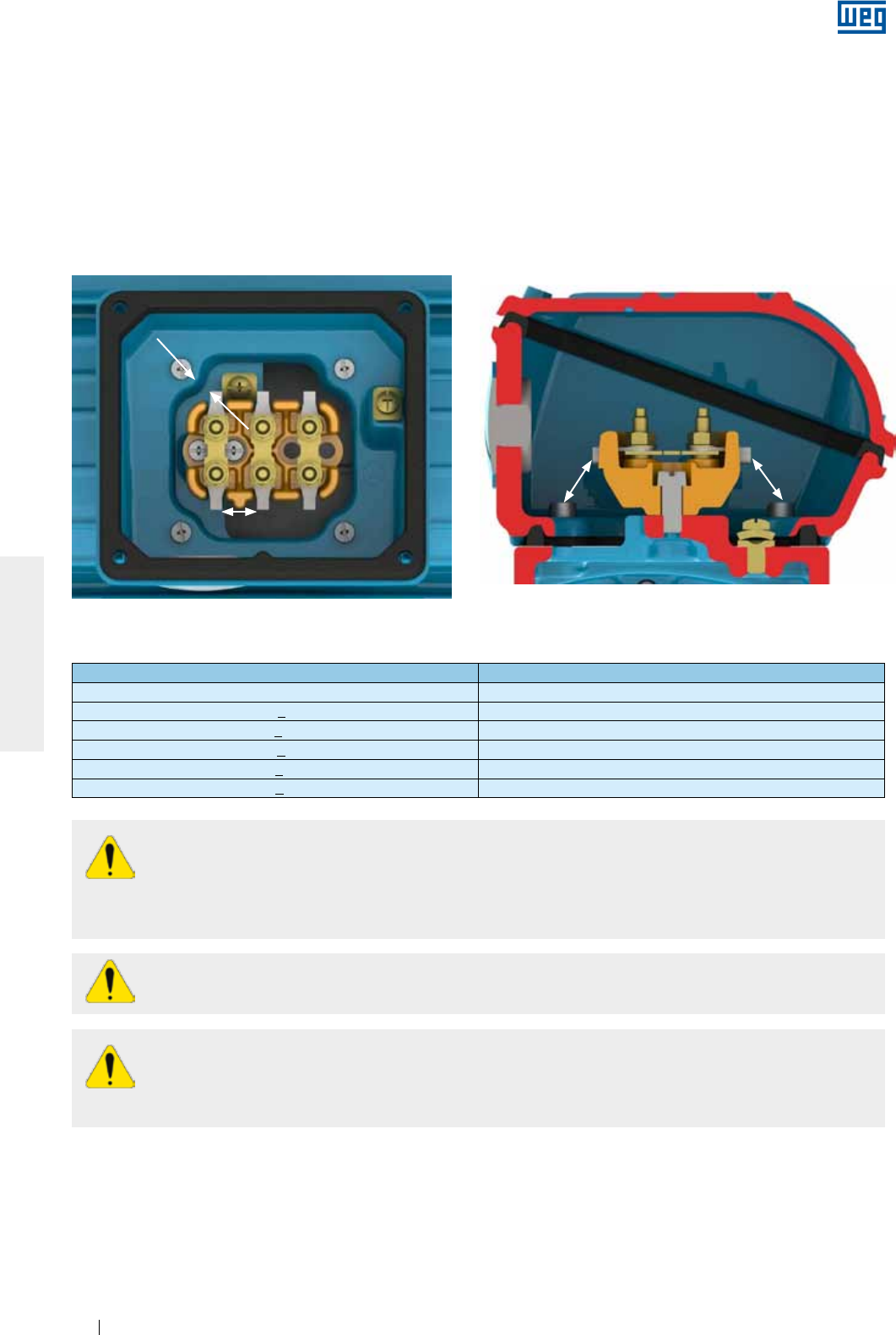
www.weg.net
Elektrische Motoren198
DEUTSCH
Es muss sichergestellt werden, dass der Motor ordnungsgemäß über sichere und dauerhafte Kontakte am
Versorgungsnetz angeschlossen ist.
Werden die Motoren ohne Klemmenbrett geliefert, müssen die Kabelklemmen des Motors entsprechend der
Versorgungsspannung und der auf dem Leistungsschild angegebenen Temperaturklasse isoliert werden.
Zum Anschluss der Versorgungskabel und des Erdungssystems bzw. Schutzleiteranschlusses müssen die in
Tabelle 8-7 angegebenen Drehmomente zur Klemmung bzw. Kontaktierung eingehalten werden.
Der Isolierabstand (Luft- und Kriechstrecke) siehe Bild 6.13, muss zwischen spannungsführenden Teilen
unterschiedlichen Potentials und geerdeten Teilen, den in Tabelle 6.3 angegebenen Werten entsprechen.
Isolierabstand
Isolierabstand
Isolierabstand Isolierabstand
Bild 6.13 - Darstellung des Isolierabstandes
Tabelle 6.3 - Mindestisolierabstand (mm) x Versorgungsspannung
Versorgungsspannung Mindestisolierabstand (mm)
(mm) 4
440 < U < 690 V 5.5
690 < U < 1000 V 8
1000 < U < 6900 V 45
6900 < U < 11000 V 70
11000< U < 16500 V 105
Auch nach dem Ausschalten des Motors, können an den Klemmen im Klemmenkasten noch
gefährliche Spannungen anliegen. Es könnte sein, dass eine Stillstandsheizung oder eine
Beheizung über die Wicklung noch in Betrieb ist. Auch wenn der Motor vom Netz getrennt ist,
können vorhandene Kondensatoren noch aufgeladen sein. Deshalb niemals die Kondensatoren und/oder
die Klemmen des Motors berühren bevor sichergestellt ist, dass sie komplett entladen sind.
Bevor Sie den Motoranschluss vornehmen, sicherstellen, dass kein Fremdkörper im Inneren des
Klemmenkastens geblieben ist.
Alle Kabeleinführungen müssen ordnungsgemäß abgedichtet sein, um den auf dem Leistungsschild
angegebenen Schutzgrad einzuhalten. Für die Versorgungs- und Steuerungskabeleinführungen müssen
immer Bauteile (z.B. Kabelverschraubungen und Kabelrohre) verwendet werden, die den einschlägigen
Normen und Sicherheitsvorschriften des betreffenden Landes entsprechen.
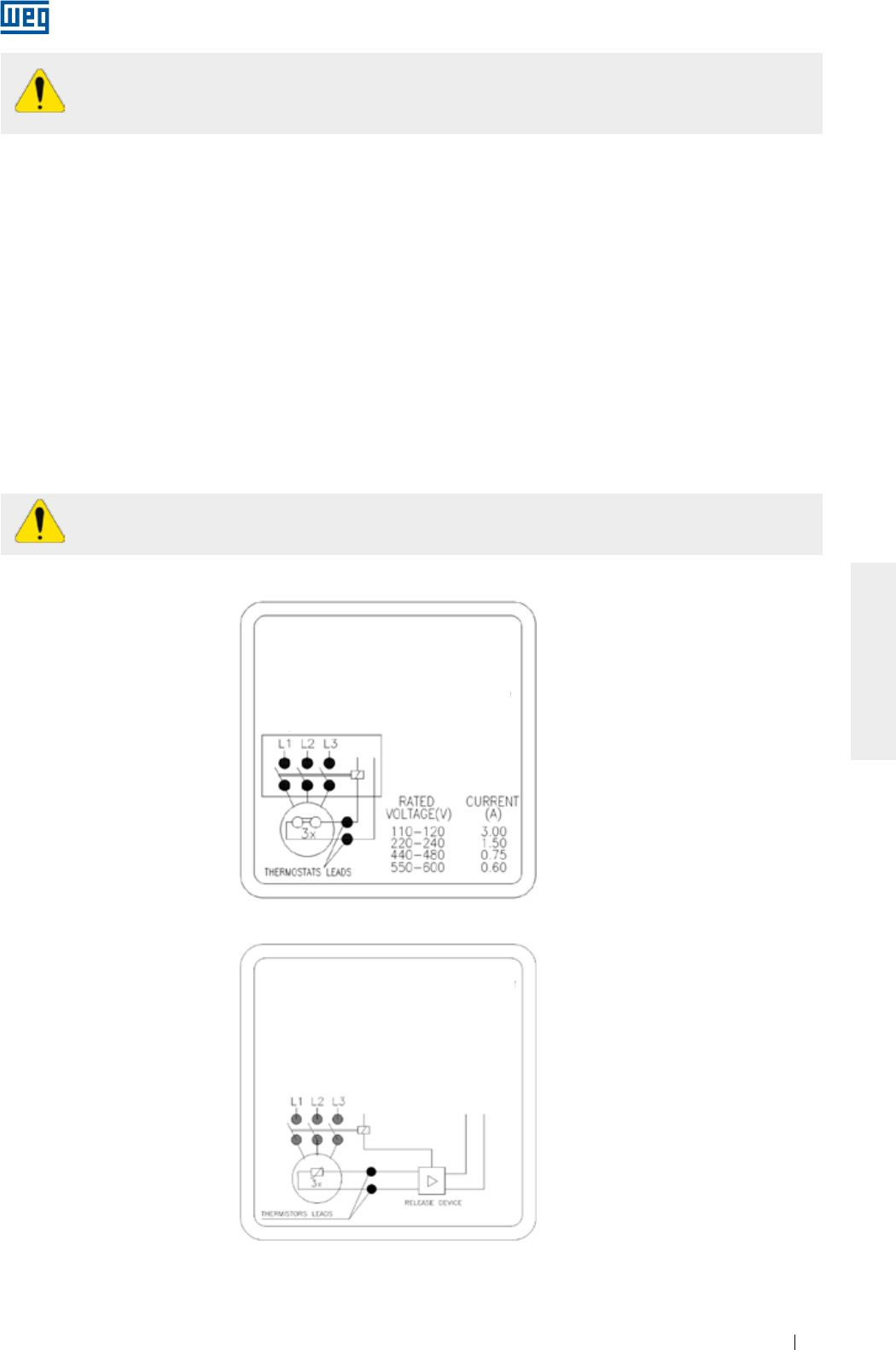
www.weg.net
Elektrische Motoren 199
DEUTSCH
Hat der Motor zusätzliches Zubehör, wie Bremse oder ein Fremdbelüftungssystem, müssen diese
entsprechend nach den auf dem Leistungsschild angegebenen Angaben, an das Versorgungsnetz
der o.g. Vorgehensweise angeschlossen werden.
Gemäß Norm IEC 60751, darf an Thermistoren (PTC´s, Kaltleiter) keine Gleichspannung ≤ 2,5 V je
Fühler und an RTD´s (Pt-100) keinen Prüfstrom größer als 1 mA angelegt werden.
Alle Schutzvorrichtungen, einschließlich der gegen Überstrom, müssen unter Berücksichtigung der
Bemessungsdaten des Motors eingestellt werden. Diese stromabhängige Überlastschutzeinrichtung, mit
zusätzlichem Phasenausfallschutz, muss auch den Motor gegen Kurzschluss und blockiertem Läufer schützen.
Die Einstellung der Überlastschutzeinrichtung muss nach den einschlägigen Normen und
Sicherheitsvorschriften vorgenommen werden.
Den Drehsinn des Motors überprüfen. Sind keine Einschränkungen des Drehsinns von Lüftern vorgesehen,
kann der Drehsinn von Drehstrommotoren durch Austausch von zwei Phasen untereinander geändert werden.
Für Einphasen-Motoren ist immer das auf dem Leistungsschild angegebene Schaltbild zu berücksichtigen.
6.10. SCHALTUNG VON THERMISCHEN SCHUTZVORRICHTUNGEN
Ist der Motor mit einer Temperaturüberwachungsvorrichtung, wie Bimetall-Schalter (Thermostate),
Thermistoren, automatische Temperaturfühler, PT-100-Fühler (RTD), usw. ausgerüstet und geliefert, müssen
diese über ihre Klemmen an die Steuerungsvorrichtung gemäß den Angaben der entsprechenden
Leistungsschilder für Zubehör geschaltet werden. Ein Nichtbefolgen dieses Verfahrens kann die Gewährleistung
aufheben und Risiken für die Installation zur Folge haben.
Bild 6.14 bzw. Bild 6.15 zeigen das Schaltbild für Bimetall-Schalter (Thermostate) und Thermistoren (PTC’s).
Bild 6.14 - Schaltbild von Bimetall-Schaltern (Thermostaten)
Bild 6.15 - Schaltbild von Thermistoren (PTC´s)
Motor thermisch
über Thermostat
geschützt
Overtemperature
protected motor with
thermostats
Overtemperature
protected motor with
thermistors
Motor termicamente
protegido com
termostatos
Motor termicamente
protegido com
termistores
Motor termicamente
protegido con
termostatos
Motor termicamente
protegido con
termistores
Stop switch
Motor thermisch
über Thermistoren
geschützt
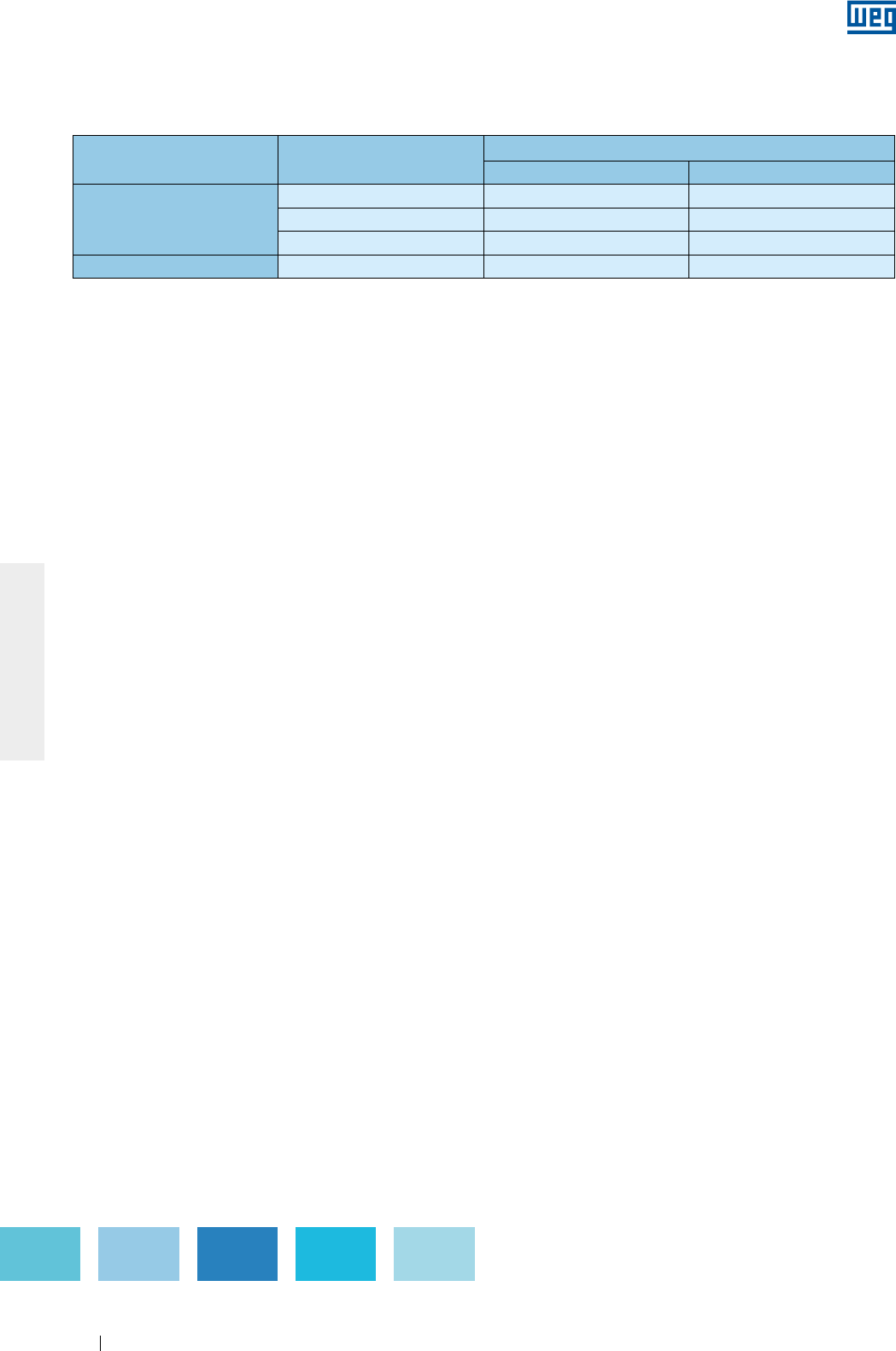
www.weg.net
Elektrische Motoren200
DEUTSCH
Die Grenztemperaturen für Alarm und Abschaltung der thermischen Schutzvorrichtungen können je nach
Einsatz bzw. Wärmelasse bestimmt werden, dürfen aber in keinem Fall die in der Tabelle 6.4 angegebenen
Werte überschreiten.
Bauteil Wärmeklasse Max. Auslösetemperatur (°C)
Alarm Abschaltung
Wicklung
B - 130
F 130 155
H 155 180
Lager Alle 110 120
Tabelle 6.4 - Max. Auslösetemperaturen der thermischen Schutzvorrichtungen
Bemerkungen:
1) Die Anzahl der im Motor installierten thermischen Schutzvorrichtungstypen sind dem Leistungsschild des entsprechenden Zubehörs zu
entnehmen.
2 Wird der Motor über kalibrierte Widerstände (z.B. PT100) geschützt, muss die Schutzvorrichtung nach der in Tabelle 6.4 angegebenen
Betriebstemperatur eingestellt werden.
6.11. WIDERSTANDSTHERMOMETER (PT-100)
Widerstandsthermometer (Pt100) bestehen normalerweise aus einem Platin oder Nickel geeichten Widerstand,
dessen Arbeitsweise sich auf dem Prinzip des elektrischen Widerstandes eines metallischen Leiters gründet,
der sich linear mit der Temperatur ändert. Dadurch ist eine ständige Überwachung der Maschinenerwärmung
auf dem Bildschirm des Reglers mit hoher Genauigkeit und Antwortempfindlichkeit sichergestellt.
Diese Schutzvorrichtung wird in den verschiedensten Anwendungsbereichen der Messtechnik,
Automatisierung der Temperaturüberwachung in der Industrie eingesetzt. Derselbe Temperaturfühler kann
sowohl für Alarm als auch für Abschaltung eingesetzt werden.
Die Tabelle 6.5 und das Bild 6.16 zeigen die Äquivalenz zwischen dem Widerstand des Pt-100 und der
Temperatur.
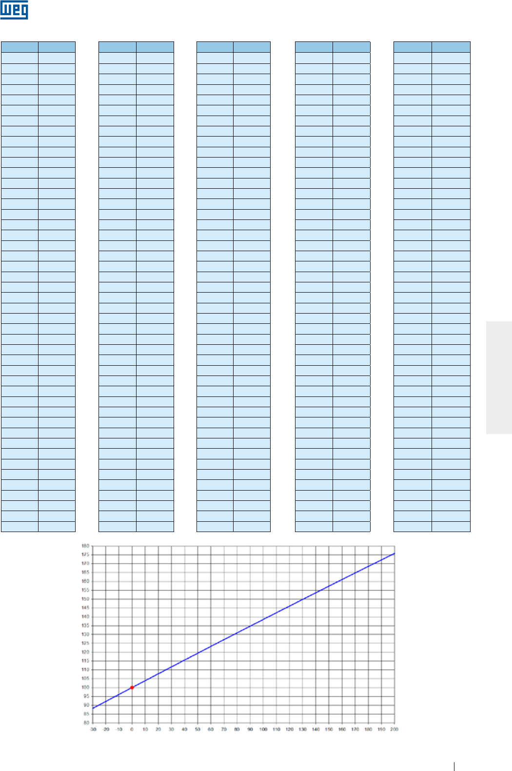
www.weg.net
Elektrische Motoren 201
DEUTSCH
ºC ºC ºC ºC ºC
-29 88.617 17 106.627 63 124.390 109 141.908 155 159.180
-28 89.011 18 107.016 64 124.774 110 142.286 156 159.553
-27 89.405 19 107.404 65 125.157 111 142.664 157 159.926
-26 89.799 20 107.793 66 125.540 112 143.042 158 160.298
-25 90.193 21 108.181 67 125.923 113 143.420 159 160.671
-24 90.587 22 108.570 68 126.306 114 143.797 160 161.043
-23 90.980 23 108.958 69 126.689 115 144.175 161 161.415
-22 91.374 24 109.346 70 127.072 116 144.552 162 161.787
-21 91.767 25 109.734 71 127.454 117 144.930 163 162.159
-20 92.160 26 110.122 72 127.837 118 145.307 164 162.531
-19 92.553 27 110.509 73 128.219 119 145.684 165 162.903
-18 92.946 28 110.897 74 128.602 120 146.061 166 163.274
-17 93.339 29 111.284 75 128.984 121 146.438 167 163.646
-16 93.732 30 111.672 76 129.366 122 146.814 168 164.017
-15 94.125 31 112.059 77 129.748 123 147.191 169 164.388
-14 94.517 32 112.446 78 130.130 124 147.567 170 164.760
-13 94.910 33 112.833 79 130.511 125 147.944 171 165.131
-12 95.302 34 113.220 80 130.893 126 148.320 172 165.501
-11 95.694 35 113.607 81 131.274 127 148.696 173 165.872
-10 96.086 36 113.994 82 131.656 128 149.072 174 166.243
-9 96.478 37 114.380 83 132.037 129 149.448 175 166.613
-8 96.870 38 114.767 84 132.418 130 149.824 176 166.984
-7 97.262 39 115.153 85 132.799 131 150.199 177 167.354
-6 97.653 40 115.539 86 133.180 132 150.575 178 167.724
-5 98.045 41 115.925 87 133.561 133 150.950 179 168.095
-4 98.436 42 116.311 88 133.941 134 151.326 180 168.465
-3 98.827 43 116.697 89 134.322 135 151.701 181 168.834
-2 99.218 44 117.083 90 134.702 136 152.076 182 169.204
-1 99.609 45 117.469 91 135.083 137 152.451 183 169.574
0 100.000 46 117.854 92 135.463 138 152.826 184 169.943
1 100.391 47 118.240 93 135.843 139 153.200 185 170.313
2 100.781 48 118.625 94 136.223 140 153.575 186 170.682
3 101.172 49 119.010 95 136.603 141 153.950 187 171.051
4 101.562 50 119.395 96 136.982 142 154.324 188 171.420
5 101.953 51 119.780 97 137.362 143 154.698 189 171.789
6 102.343 52 120.165 98 137.741 144 155.072 190 172.158
7 102.733 53 120.550 99 138.121 145 155.446 191 172.527
8 103.123 54 120.934 100 138.500 146 155.820 192 172.895
9 103.513 55 121.319 101 138.879 147 156.194 193 173.264
10 103.902 56 121.703 102 139.258 148 156.568 194 173.632
11 104.292 57 122.087 103 139.637 149 156.941 195 174.000
12 104.681 58 122.471 104 140.016 150 157.315 196 174.368
13 105.071 59 122.855 105 140.395 151 157.688 197 174.736
14 105.460 60 123.239 106 140.773 152 158.061 198 175.104
15 105.849 61 123.623 107 141.152 153 158.435 199 175.472
16 106.238 62 124.007 108 141.530 154 158.808 200 175.840
Tabelle 6.5 - Äquivalenz zwischen dem Widerstand des Pt-100 (Platin) und der Temperatur
Bild 6.16 - Ohm’scher Widerstand des Pt-100 (Platin) x Temperatur
Widerstand (Ohm)
Temperatur (°C)
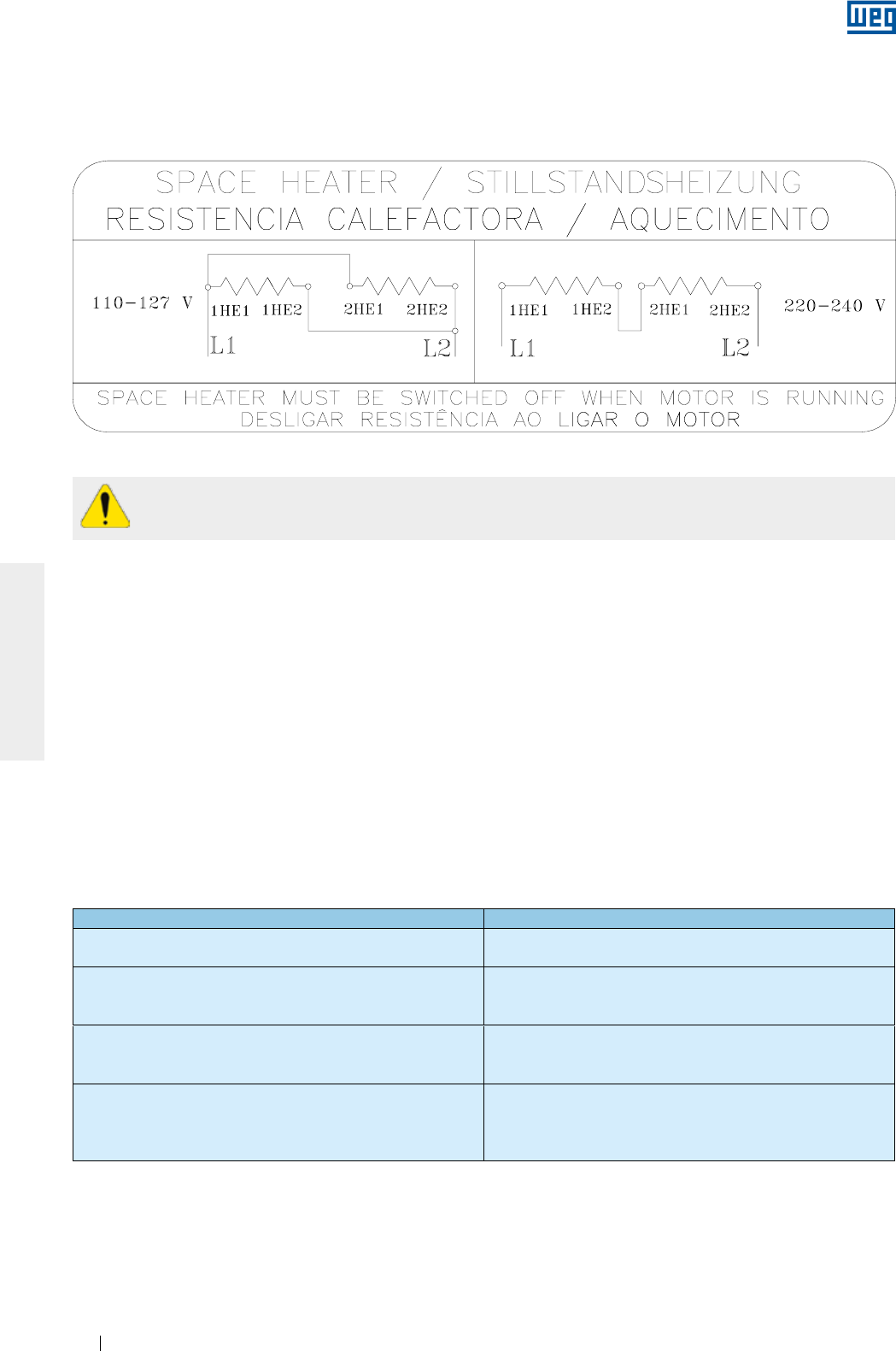
www.weg.net
Elektrische Motoren202
DEUTSCH
6.13. ANLAUFMETHODEN
6.12. ANSCHLUSS DER STILLSTANDSHEIZUNG
Wenn möglich, sollte ein Drehstrom-Käfigläufer-Motor direkt am Netz eingeschaltet werden können. Die
Direkteinschaltung ist möglich, aber nur dann zugelassen, wenn der Anlaufstrom das Drehstromnetz nicht
beeinträchtigt. Hier müssen immer die Regelungen und Gesetzgebungen der örtlichen Stromverteiler
berücksichtigt werden. Zu hohe Anlaufströme können folgende Beeinträchtigungen zur Folge haben:
a) Einen hohen Spannungsabfall im Stromnetz, was die Betriebsbedingungen anderer Geräte beeinträchtigt;
b) Die Bauteile für den elektrischen Anschluss (Kabel, Schütze) müssen überdimensioniert werden, was die
Anschaffungskosten erhöht.
Ist die Direkteinschaltung nicht wegen der o.g. Folgen oder wegen Forderungen der Anlage zugelassen, können
indirekte Schaltungssysteme mit verminderter Spannung zur Minderung des Anlaufstromes eingesetzt werden. Wird
eine Anlaufmethode mit reduzierter Spannung gewählt, wird die Maschine auch quadratisch reduziertes
Anlaufdrehmoment liefern
Der Anschluss der Stillstandsheizung muss gemäß dem angegebenen Schaltbild auf dem zusätzlichen
Leistungsschild entsprechend vorgenommen werden. Werden die Stillstandsheizungen für zwei Spannungen
ausgeführt geliefert, muss die Schaltung gemäß Bild 6.17 gemacht werden.
Bild 6.17 - Schaltbild der Stillstandsheizung für 110-127/220-240 V
Während des Betriebes darf die Stillstandsheizung nicht eingeschaltet sein.
Anzahl der Klemmen Mögliche Anlaufmethoden
3 Klemmen Spartransformator
Sanftanlasser
6 Klemmen
Stern-Dreieck-Schalter
Spartransformator
Sanftanlasser
9 Klemmen
Stern-Dreieck-Schalter
Spartransformator
Soft - Starter
12 Klemmen
Stern-Dreieck-Schalter
Reihen - Parallelschalter
Spartransformator
Sanftanlasser
Tabelle 6.6 - Anlaufmethoden x Klemmenzahl
Die Tabelle 6.6 zeigt die möglichen indirekten Anlaufmethoden unter Berücksichtigung der Anzahl der
ausgeführten Klemmen des Motors.
Die Tabelle 6.7 zeigt mögliche Beispiele für indirekte Anlaufmethoden unter Berücksichtigung der auf dem
Leistungsschild angegebenen Bemessungsspanung und der Netzspannung.
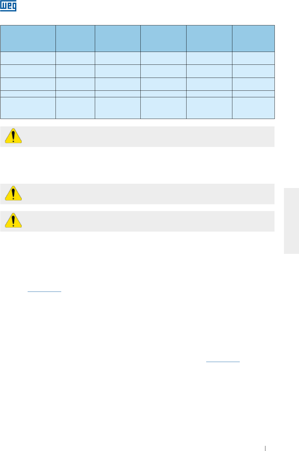
www.weg.net
Elektrische Motoren 203
DEUTSCH
Tabelle 6.7 - Anlaufmethoden x Spannung.
Auf dem
Leistungsschild
angegebene
Bemessungsspanung
Netzspannung Anlauf Stern-
Dreieck-Schalter
Anlauf über
Spartransformator
Anlauf über
Reihen- Parallel-
schalter
Anlauf über
Sanftanlasser
220/380 V 220 V
380 V
JA
NEIN
JA
JA
NEIN
NEIN
JA
JA
220/440 V 220 V
440 V
NEIN
NEIN
JA
JA
JA
NEIN
JA
JA
230/460 V 230 V
460 V
NEIN
NEIN
JA
JA
JA
NEIN
JA
JA
380/660 V 380 V JA JA NEIN JA
220/380/440 V
220 V
380 V
440 V
JA
NEIN
JA
JA
JA
JA
JA
JA
NEIN
JA
JA
JA
Die Motoren der Reihe „WQuattro“ müssen direkt an das Netz angeschlossen oder über einen
Frequenzumrichter in Skalarmethode betrieben werden.
Eine andere Anlaufmethode ist der Antrieb über einen Frequenzumrichter, was eine Überlastung des
Versorgungsnetzes vermeidet. Weitere Informationen für Antriebe über Frequenzumrichter, siehe 6.14.
6.14. MOTOREN ÜBER FREQUENZUMRICHTER BETRIEBEN
Wenn ein Antrieb über Frequenzumrichter gewünscht wird, muss dies im Auftrag angegeben
werden, da es mögliche Baugrößenunterschiede für diese Antriebsart geben kann.
Motoren der Reihe „Wmagnet“ dürfen nur über WEG-Frequenzumrichter betrieben werden.
Bei einer Versorgungsspannung, die kleiner als 690 V ist, wird der eingesetzte Frequenzumrichter mit einer
pulsweiten Modulation (PWM) ausgeführt.
Wird der Motor über einen Frequenzumrichter mit einer niedrigeren Frequenz als der Nennfrequenz betrieben,
muss das Bemessungsdrehmoment des Motors herabgesetzt werden, um so eine Überschreitung der
Erwärmung des Motors zu vermeiden. Die Reduktion des Motor-Bemessungsdrehmomentes können Sie in
Pkt. 6.4 des “Technical Guide for Induction Motors fed by PWM (Pulsweiten Modulation) Frequency Inverters”
im Internet www.weg.net finden.
Wird der Motor bei einer höheren Frequenz als der Bemessungsfrequenz betrieben, muss Folgendes
berücksichtigt werden:
g Betrieb bei konstanter Leistung;
g Der Motor darf maximal 95% seiner Bemessungsleistung liefern;
g Die max. Drehzahl unter Berücksichtigung folgender Kriterien, einhalten:
g Die max. auf dem zweiten Leistungsschild angegebene Betriebsfrequenz;
g Die mechanische Begrenzung der Motordrehzahl.
Empfehlungen für die Kabelverbindungen zwischen Motor und Frequenzumrichter sind in Pkt. 6.8 des
“Technical Guide for Induction Motors fed by PWM Frequency Inverters” im Internet www.weg.net zu finden.
6.14.1. Einsatz von Filtern (dU/dt)
6.14.1.1. Motorwicklungen mit emailliertem Runddraht
Sollen o.g. Motoren mit emailliertem Runddraht über einen Frequenzumrichter bis zu einer
Bemessungsspannung von 690 V betrieben werden, erfordern sie keinen Filtereinsatz, wenn folgende
Bedingungen eingehalten werden:
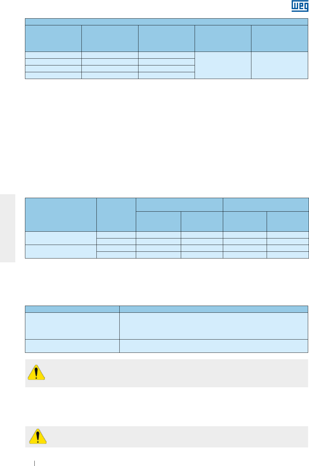
www.weg.net
Elektrische Motoren204
DEUTSCH
Kriterien zum Einsatz von Motoren mit emailliertem Runddraht über Frequenzumrichter betrieben1
Motorbemessungs-
spannung2
Motorspitzen-
spannung (max.)
dU/dt am Ausgang des
Umrichters (max.)
Anstiegszeit des
Umrichters (min.)
MTBP3
Durchschnittszeit
zwischen den Pulsen
(min.)
Vnom ≤ 460 V ≤ 1600 V ≤ 5200 V/µs
≥ 0,1 µs ≥ 6 µs
460 < Vnom ≤ 575 V ≤ 1800 V ≤ 6500 V/µs
575 < Vnom ≤ 690 V4≤ 1600 V ≤ 5200 V/µs
575 < Vnom ≤ 690 V5≤ 2200 V ≤ 7800 V/µs
1. Motoren mit emailliertem Runddraht für Spannungen 690 < Vnom ≤ 1100 V, bitte WEG ansprechen.
2. Werden Motoren für zwei Spannungen ausgelegt, z.B. 380/660V, müssen immer die Kriterien der niedrigeren
Spannung berücksichtigt werden (380V).
3. Informationen werden vom Hersteller des Frequenzumrichters.
4. Schon beim Auftrag muss angegeben sein, dass der Motor über einen Frequenzumrichter betrieben wird,
andernfalls erhält er eine Normale Wicklung ohne emaillierten Draht.
5. Wenn im Auftrag angegeben ist, dass der Motor über einen Frequenzumrichter betrieben wird, wird
der Motor mit einem emailierten Draht geliefert.
6.14.1.2. Motorwicklungen mit vorgeformten Flachdrahtspulen
Motorwicklungen mit vorgeformten Flachdrahtspulen (Mittel- und Hochspannungsmotoren, sind unabhängig
von der Baugröße und Niederspannungsmotoren ab einer Baugröße IEC 500 / NEMA 80) für Umrichterbetrieb
entwickelt, erfordern keinen Einsatz von Filtern, wenn die in Tabelle 6.8 angegebenen Bedingungen erfüllt
werden.
Werden Motoren mit einem Erdungssystem für die Welle geliefert, muss der Betriebszustand der
Erdungsbürste ständig auf Verschleiß überwacht werden und sobald ihre Grenze der Lebensdauer
erreicht ist muss sie gegen eine Neue mit derselben Spezifikation gewechselt werden.
Die Nichterfüllung der o.g. Anweisungen und Empfehlungen kann die Aufhebung der
Produktgarantie zur Folge haben.
Tabelle 6.8 - Kriterien zum Einsatz von Motorwicklungen mit vorgeformten Flachdrahtspulen für einen
Antrieb über Frequenzumrichter ohne Filter
Motorbemessungsspannung Modulationsart
Isolierung zwischen Windungen
(Phase-Phase) Hauptisolierung (Phase und Erde)
Spitzenspannung
an den
Motorklemmen
dU/dt an den
Motorklemmen
Spitzenspannung
an den
Motorklemmen
dU/dt an den
Motorklemmen
690 < Vnom ≤ 4160 V sinusförmig ≤ 5900 V ≤ 500 V/µs ≤ 3400 V ≤ 500 V/µs
PWM ≤ 9300 V ≤ 2700 V/µs ≤ 5400 V ≤ 2700 V/µs
4160 < Vnom ≤ 6600 V sinusförmig ≤ 9300 V ≤ 500 V/µs ≤ 5400 V ≤ 500 V/µs
PWM ≤ 14000 V ≤ 1500 V/µs ≤ 8000 V ≤ 1500 V/µs
6.14.2. Lagerisolierung
Ab Baugröße IEC 315 (NEMA 504/5) werden standardmäßig Motoren mit isoliertem Lager geliefert. Die
Lagerisolierung der Motoren für Umrichterbetrieb muss gemäß Tabelle 6.9 vorgenommen werden.
Tabelle 6.9 - Anweisungen für die Lagerisolierung von Motoren für Umrichterbetrieb
Baugröße Anweisung
IEC 315 und 355
NEMA 445/7, 447/9, L447/9, 504/5,
5006/7/8, 5009/10/11, 586/7, 5807/8/9,
5810/11/12 und 588/9
Ein Lager isolieren
Erdung zwischen Welle und Gehäuse mit Erdungsbürste
IEC 400 und größer
NEMA 6800 und größer
Lager an der Nichtantriebsseite isolieren
Erdung zwischen Welle und Gehäuse mit Erdungsbürste
6.14.3. Schaltfrequenz
Die niedrigste Schaltfrequenz des Frequenzumrichters ist 2,5 kHz.
Die höchste empfohlene Schaltfrequenz des Frequenzumrichters sollte 5 kHz nicht übersteigen.
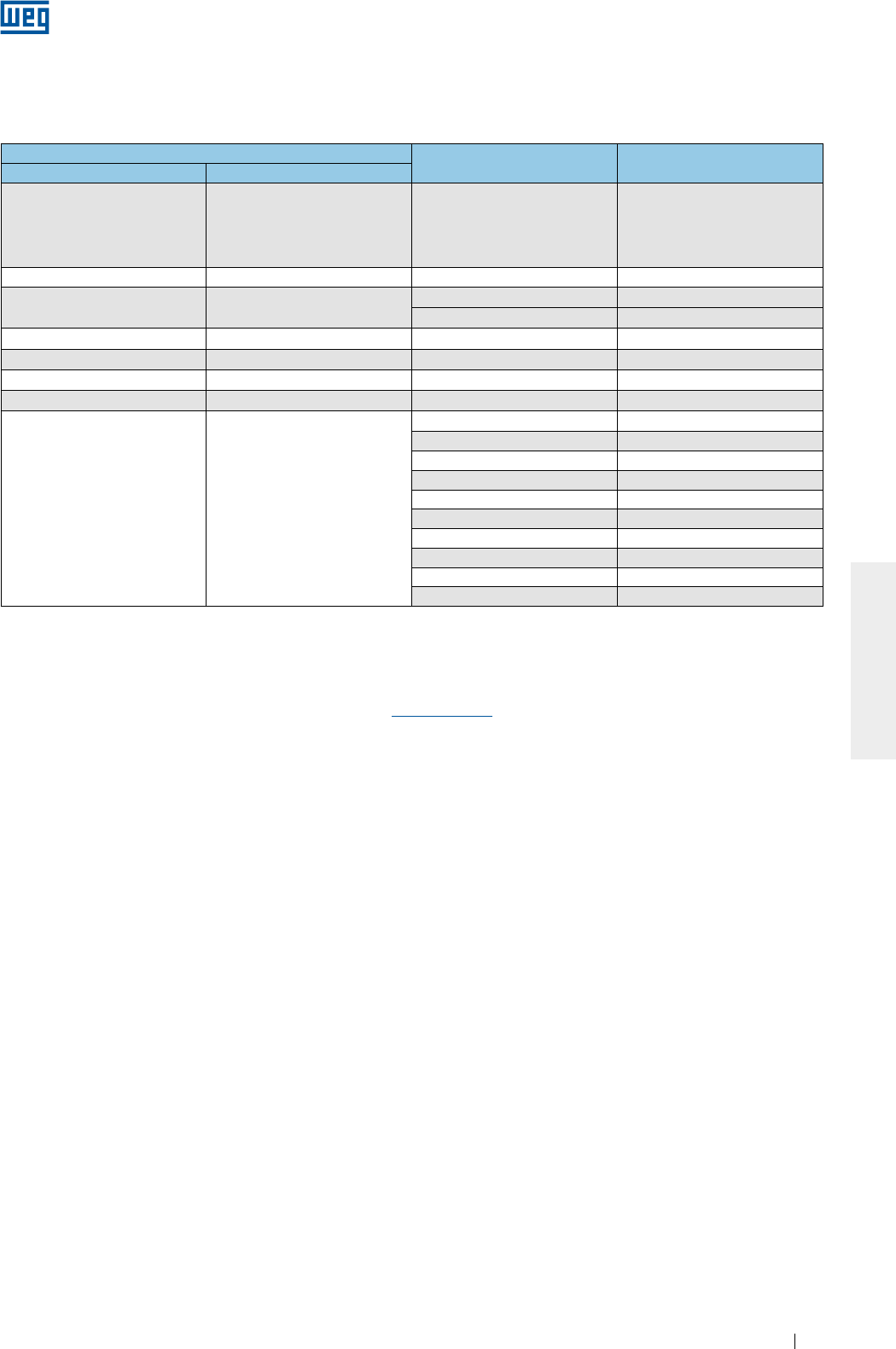
www.weg.net
Elektrische Motoren 205
DEUTSCH
6.14.4. Beschränkungen der mechanischen Drehzahl
Tabelle 6.10 zeigt die max. zugelassenen Drehzahlen für Motoren mit Frequenzumrichter betrieben.
Tabla 6.10 - Max. zugelassene Drehzahl für den Motor (min-1)
Bemerkung: zur Auswahl der max. zugelassenen Drehzahl, muss die Reduktionskennlinie des Motordrehmomentes berücksichtigt
werden.
Für weitere Informationen über den Einsatz von Frequenzumrichtern und ihre ordnungsgemäße Auswahl für
den gewünschten Einsatz, bitten wir Sie die Firma WEG anzusprechen oder den “Technical Guide for Induction
Motors fed by PWM Frequency Inverters” im Internet www.weg.net zu besuchen.
Baugröße Lager Antriebsseite Max. Drehzahl für
Standardmotor
IEC NEMA
63-90 143/5
6201
6202
6203
6204
6205
10400
100 - 6206 8800
112 182/4 6207 7600
6307 6800
132 213/5 6308 6000
160 254/6 6309 5300
180 284/6 6311 4400
200 324/6 6312 4200
225-630 364/5-9610
6314 3600
6315 3600
6316 3200
6319 3000
6220 3600
6320 2200
6322 1900
6324 1800
6328 1800
6330 1800
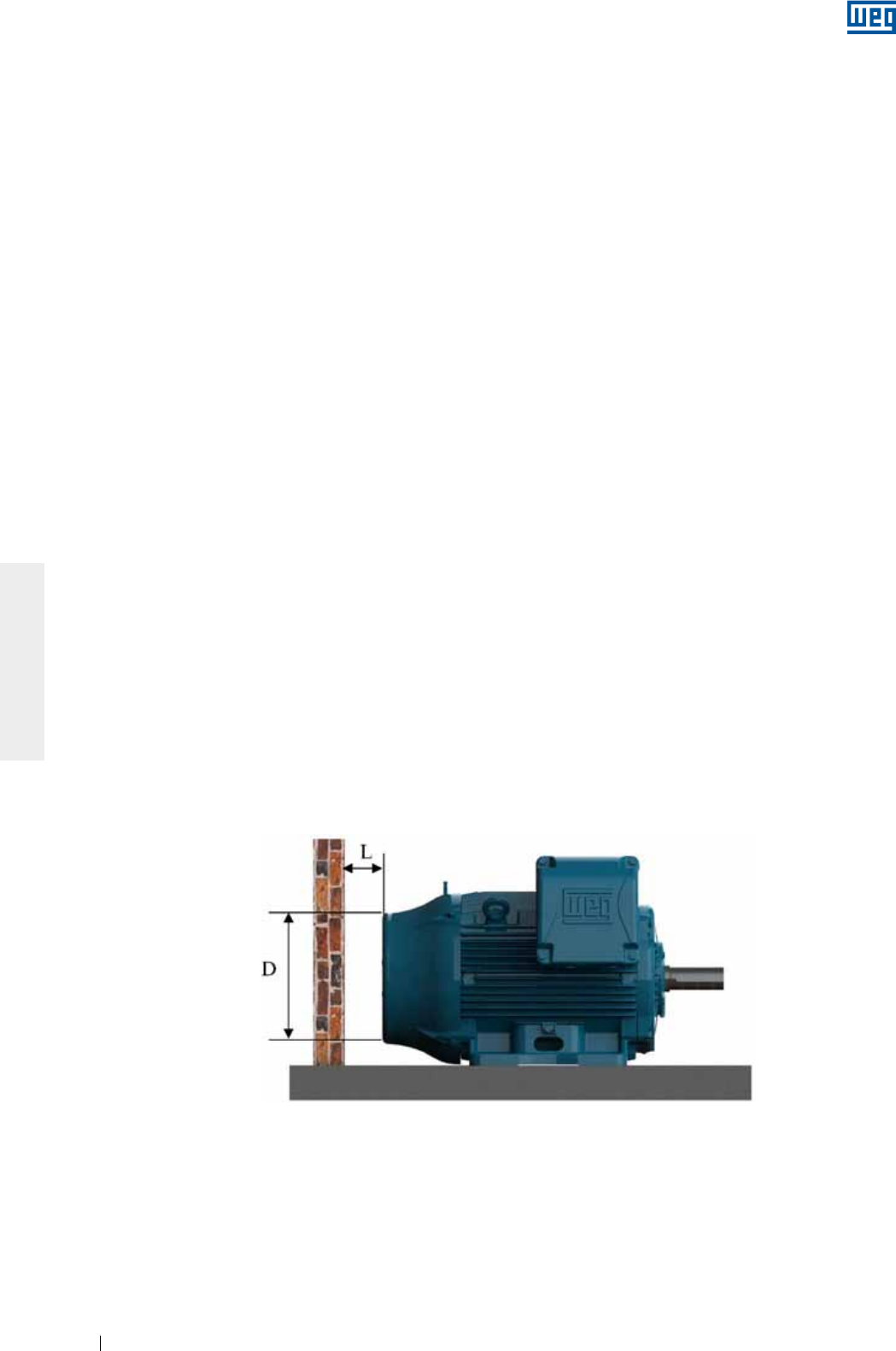
www.weg.net
Elektrische Motoren206
DEUTSCH
7. INBETRIEBNAHME
7.1. ERSTSTART
Bevor der Motor nach Aufbau und Installation in Betrieb genommen wird, sind vor einer Inbetriebnahme
folgende Punkte zu überprüfen:
g Stimmen die auf dem Leistungsschild angegebenen Daten (Bemessungsspannung, Bemessungsstrom,
Schaltbild, Schutzart, Kühlung, Betriebsfaktor, usw.) mit dem Einsatz überein;
g Ist die Montage und Ausrichtung des Motors + angetriebener Maschine ordnungsgemäß ausgeführt worden;
g Ist sichergestellt, dass das Antriebssystem des Motors, nicht die in Tabelle 6.10 max. zugelassene
Motordrehzahl überschreitet;
g Ob die Stillstandsheizung gemäß Pkt. 5.4 installiert wurde;
g Ob die Drehrichtung des Motors mit der angetriebenen Maschine übereinstimmt;
g Sicherstellen, dass der Klemmenkasten sauber und trocken ist, seine Kontakte frei von Oxydation sind, die
Dichtungen in einwandfreiem Zustand sind und die Kabeleinführungen ordnungsgemäß geschlossen/
geschützt sind und der auf dem Leistungsschild angegebenen Schutzart entsprechen;
g Ob die Kabelverbindungen des Motors, einschließlich der Erdung und die Verbindungen des Zubehörs
ordnungsgemäß nach den Anweisungen in Pkt. 6.9 vorgenommen wurden;
g Ob das am Motor angebaute Zubehör (Bremse, Encoder, thermische Schutzvorrichtungen , Fremdkühlung,
usw.) betriebstüchtig sind;
g Sollte ein bereits eingelagerter Motor erstmalig zum Einsatz kommen, ist der Betriebszustand der Wälzlager
zu überprüfen. Wälzlager mit Oxydationszeichen müssen gewechselt werden. Sind die Wälzlager
oxydationsfrei, Nachschmierung nach Pkt. 8,5 vornehmen. Werden Motoren länger als zwei Jahre gelagert,
müssen die Wälzlager vor der Inbetriebnahme gewechselt werden;
g Bei Motoren mit Gleitlagern, muss sichergestellt werden, dass:
g Der Ölstand richtig ist. Der Ölstand muss sich in der Mitte des Ölstandschauglases befinden (siehe Bild 6.9);
g Sicherstellen, dass der Motor nicht mit zu hohen Radial- und Axiallasten anläuft oder betrieben wird;
g Sollte ein bereits eingelagerter Motor, länger als die empfohlen Nachschmierfristen, erstmalig zum Einsatz
kommen, muss das Öl vor der Inbetriebnahme gewechselt werden.
g Werden Einphasenmotoren länger als zwei Jahre vor dem Erststart gelagert, müssen die
Anlasskondensatoren vor der Inbetriebnahme gewechselt werden, da sie nach längerer Lagerungszeit ihre
Betriebseigenschaften verlieren können;
g Die Luftein- und Luftauslässe dürfen nicht abgedeckt oder verstopft sein. Der empfohlene Einbauabstand
zwischen der Lufteintrittsöffnung des Motors und einer Wand (L) muss wenigstens ¼ des Durchmessers der
Lufteintrittsöffnung betragen, siehe Bild 7.1. Die Temperatur der angesaugten Kühlluft muss gleich der
Umgebungstemperatur sein und darf niemals die auf dem Leistungsschild angegebene Grenztemperatur
überschreiten.
Bild 7.1 - Mindestabstand zwischen dem Motor und der Wand
Die in Tabelle 7.1 angegebene Mindestabstände sind als Referenzwerte anzusehen;

www.weg.net
Elektrische Motoren 207
DEUTSCH
Tabelle 7.1 - Mindestabstand zwischen Lüfterhaube und Wand
g Bei wassergekühlten Motoren sind die Wassermenge und die Wassertemperatur zu überwachen. Siehe Pkt. 7.2;
g Es ist sicherzustellen, dass gegen zufällige Unfälle, drehende Teile, wie Riemenscheiben, Kupplungen,
Fremdlüfter, Welle, usw. ordnungsgemäß geschützt sind.
Die hier nicht aufgezeigten Prüfungen und Maßnahmen können wegen z.B. spezifischer Einbaueigenschaften,
oder anderen Anwendungsbedingungen sowie Maschineneigenschaften erforderlich sein.
Nachdem alle o.g. Überprüfungen durchgeführt wurden, kann der Motorstart wie folgt, vorgenommen werden:
g Die Maschine im Leerlauf (wenn möglich) starten und die Drehrichtung des Motors überprüfen. Die Maschine auf
abnormales Geräusch, Schwingungen oder auf sonstige Betriebsbedingungen überprüfen;
g Die Maschine jetzt neu starten und überprüfen, ob sie sanft anläuft. Werden anormale Betriebsbedingungen
festgestellt, ist die Maschine sofort wieder vom Netzt zu trennen, das Montagesystem und die Verbindungen
sind vor einem Neustart zu überprüfen;
g Werden zu hohe Schwingungen festgestellt, überprüfen, ob die Maschinenbefestigungsschrauben fest
angezogen sind oder ob die Schwingungen von angebauten Maschinen in der Umgebung übertragen
werden. Die Maschinenschwingung muss in bestimmten Zeitabständen überprüft werden und es muss
sichergestellt werden, dass die in Pkt. 7.2.1 angegebenen Grenzwerte nicht überschritten werden;
g Die Maschine während kurzer Zeit bei Bemessungslast betreiben und den Betriebsstrom mit dem auf dem
Leistungsschild angegebenen Bemessungsstrom vergleichen;
g Es wird empfohlen einige Variablen der Maschine und des Motors bis zum Erreichen des thermischen
Gleichgewichtes zu überwachen: Strom, Spannung, Lager- und Gehäusetemperatur, Schwingungs- und
Geräuschpegel;
g Es wird empfohlen, dass die gemessenen Strom- und Spannungswerte in einem Inbetriebnahmebericht für
künftige Vergleiche einzutragen sind.
Da Asynchronmaschinen einen hohen Anlaufstrom beim Start aufweisen, verlängert sich die Zeit zur
Beschleunigung von Lasten mit einem hohen Trägheitsmoment, was einen schnellen Temperaturanstieg des
Motors zu Folge hat. Kurze Zeitabstände zwischen aufeinanderfolgenden Anläufen, haben einen schnellen
Temperaturanstieg der Wicklung zur Folge, was die Gefahr einer Beschädigung und letzten Endes eine
Verminderung der Lebensdauer wäre. Ist auf dem Leistungsschild die Betriebsart S1 (Dauerbetrieb)
angegeben, bedeutet das, dass der Motor für folgende Betriebsart ausgelegt ist:
g Zwei unmittelbar aufeinander folgende Anläufe: der erste Anlauf aus dem kalten Zustand, d. h. bei kalter
Wicklungstemperatur und der zweite Anlauf sofort nachdem der Motor wieder zum Stillstand gekommen ist;
g Aber nur einen Anlauf im betriebswarmen Zustand, d.h. die Wicklung hat ihre Nenn-Betriebstemperatur
erreicht.
Das Fehlersuche-Diagramm in Pkt. 10 zeigt einige Betriebsstörungen mit ihren wahrscheinlichen Ursachen.
Baugröße Einbauabstand zwischen der Lüfterhaube und der Wand (L)
IEC NEMA mm inches
63 - 25 0,96
71 - 26 1,02
80 - 30 1,18
90 143/5 33 1,30
100 - 36 1,43
112 182/4 41 1,61
132 213/5 50 1,98
160 254/6 65 2,56
180 284/6 68 2,66
200 324/6 78 3,08
225
250
364/5
404/5 85 3,35
280
444/5
445/7
447/9
108 4,23
315
L447/9
504/5
5006/7/8
5009/10/11
122 4,80
355
586/7
588/9
5807/8/9
5810/11/12
136 5,35
400 6806/7/8
6809/10/11 147 5,79
450 7006/10 159 6,26
500 8006/10 171 6,73
560 8806/10 185 7,28
630 9606/10 200 7,87
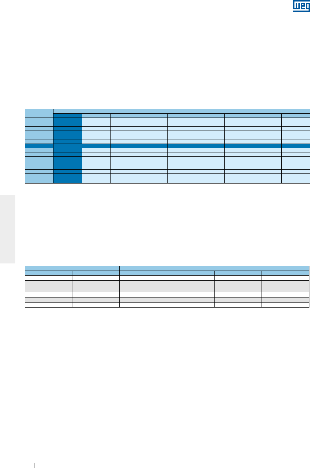
www.weg.net
Elektrische Motoren208
DEUTSCH
T (°C) Aufstellungshöhe (m)
1000 1500 2000 2500 3000 3500 4000 4500 5000
10 0,97 0,92 0,88
15 0,98 0,94 0,90 0,86
20 1,00 0,95 0,91 0,87 0,83
25 1,00 0,95 0,93 0,89 0,85 0,81
30 1,00 0,96 0,92 0,90 0,86 0,82 0,78
35 1,00 0,95 0,93 0,90 0,88 0,84 0,80 0,75
40 1,00 0,97 0,94 0,90 0,86 0,82 0,80 0,76 0,71
45 0,95 0,92 0,90 0,88 0,85 0,81 0,78 0,74 0,69
50 0,92 0,90 0,87 0,85 0,82 0,80 0,77 0,72 0,67
55 0,88 0,85 0,83 0,81 0,78 0,76 0,73 0,70 0,65
60 0,83 0,82 0,80 0,77 0,75 0,73 0,70 0,67 0,62
65 0,79 0,76 0,74 0,72 0,70 0,68 0,66 0,62 0,58
70 0,74 0,71 0,69 0,67 0,66 0,64 0,62 0,58 0,53
75 0,70 0,68 0,66 0,64 0,62 0,60 0,58 0,53 0,49
80 0,65 0,64 0,62 0,60 0,58 0,56 0,55 0,48 0,44
7.2. BETRIEB
Ist im Auftrag keine Angabe besonderer Betriebsbedingungen angegeben, sind die elektrischen Motoren für
eine Aufstellungshöhe bis zu 1000 m über NN und für eine Kühlmitteltemperatur von -20 °C bis +40 °C
ausgelegt.
Sonderbetriebsbedingungen müssen im Auftrag festgelegt und auf dem Leistungsschild und in dem
entsprechenden Datenblatt der Maschine eingetragen sein.
Soll der Motor für eine andere Kühlmitteltemperatur, als die o. g. eingesetzt werden, müssen einige Bauteile
gewechselt werden. In diesem Fall, bitten wir Sie die Firma WEG für diese Sondereigenschaften anzusprechen.
Für andere Kühlmitteltemperaturen und Aufstellungshöhen, bitten wir Sie den in Tabelle 7.2 angegebenen
Korrekturfaktor zur Festlegung der nutzbaren Leistung (Pmax = Pnom x Korrekturfaktor) zu Grunde zu legen.
Werden Motoren in geschlossenen Räumen aufgestellt, muss die Umgebung am Aufstellungsort in der Lage
sein, einen Luftaustausch entsprechend der installierten Motorleistung sicherstellen. In der Größenordnung von
1 m³/s pro 100 kW im Verhältnis der installierten Leistung, also1,5 m³/s bei 150 kW, zu gewährleisten. Für
Motoren, die keine Eigenbelüftung haben, ist der Betreiber des Gerätes für die geeignete Belüftung
verantwortlich.
Sind auf dem Leistungsschild keine Vorgaben für die minimale Strömungsgeschwindigkeit zwischen den
Kühlrippen angegeben, sollte die in Tabelle 7.3 angegebene Strömungsgeschwindigkeit sichergestellt werden.
Die in Tabelle 7.3 angegebenen Werte sind für 60 Hz Motoren gültig. Um die min. geforderte
Strömungsgeschwindigkeit für 50 Hz Motoren sicherzustellen, müssen die Werte in Tabelle 7.3 mit 0,83
multipliziert werden.
Tabelle 7.3 - Min. Strömungsgeschwindigkeit zwischen den Kühlrippen (m/s)
Tabelle 7.2 - Korrekturfaktoren unter Berücksichtigung der Umgebungstemperatur und Aufstellungshöhe
Baugröße Polzahl
IEC NEMA 2 4 6 8
63 bis 90 143/5 14 7 5 4
100 bis 132 182/4 und
213/5 18 10 8 6
160 bis 200 364/5 bis 444/5 20 20 12 7
225 bis 280 364/5 bis 444/5 22 22 18 12
315 bis 355 445/7 bis 588/9 25 25 20 15
Schwankungen der Versorgungsspannung und Frequenz können die Betriebseigenschaften des Motors
beeinflussen. Die Schwankungen der Versorgungsspannung und Frequenz sollten nicht die angegebenen
Werte in den gültigen Normen überschreiten. Beispiele:
g IEC 60034-1. Der Motor ist ausgelegt um das Bemessungsdrehmoment bei folgenden kombinierten
Schwankungen der Spannung und der Frequenz zu liefern:
g Zone A: 5% der Spannung und 2% der Frequenz;
g Zone B: 10% der Spannung und +3% -5% der Frequenz.
Wird der Motor gemäß der auf dem Leistungsschild angegebenen Daten ständig in Zone A oder B betrieben,
kann sich die Betriebstemperatur für Zone B erheblich erhöhen. Diese Schwankungen sind größer für den
Betrieb in Zone B. Deshalb wird empfohlen die Maschine nicht für längere Zeit in Zone B zu betreiben. Für
Mehrspannungsbereichmotoren (z. B., 380-415/660 V), ist eine Spannungsschwankung von 5% zugelassen.
g NEMA MG 1 Teil 12. Der Motor ist für folgende Spannungs- und Frequenzschwankung ausgelegt:
g 10% der Bemessungsspannung bei Bemessungsfrequenz;
g 5 der Frequenz bei Bemessungsfrequenz;
g Eine kombinierte Spannungs- und Frequenzschwankung von 10% ist zugelassen, sofern die
Frequenzschwankung nicht größer als 5% ist.
g ABNT NBR 17094 - Teil 1 und 2. Der Motor ist ausgelegt um das Bemessungsdrehmoment bei folgenden
Schwankungen der Spannung und der Frequenz zu liefern:
g Zone A: 5% der Spannung und 2% der Frequenz;
g Zone B: 10% 10% der Spannung und +3% -5% der Frequenz.
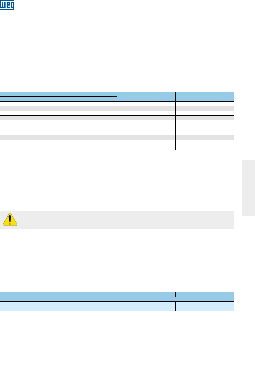
www.weg.net
Elektrische Motoren 209
DEUTSCH
Tabla 7.4 - Min. geforderte Wassermenge und zugelassener Temperaturanstieg nachdem das Wasser durch den Motor geflossen ist
Baugöße Wassermenge
(Liter/Minute)
Max. zugegelassener
Wassertemperaturanstieg (°C)
IEC NEMA
180 284/6 12 5
200 324/6 12 5
225 364/5 12 5
250 404/5 12 5
280
444/5
445/7
447/9
15 6
315 504/5 16 6
355 586/7
588/9 25 6
Sollte bei Motoren mit Schmierölnebel geschmierten Wälzlagern (oil mist), das Ölpumpensystem ausgefallen
sein, darf der Motor im Dauerbetrieb noch max. eine Stunde betrieben werden.
Da eine direkte Sonneneinstrahlung die Temperatur am Motor erhöht, müssen Motoren bei Außenaufstellung
immer unter einem Dach aufgestellt werden.
Bei Störungen im Normalbetrieb, z.B. (Auslösung der thermischen Schutzvorrichtungen, Veränderungen des
Geräusch- und Schwingungspegels oder ein plötzlicher Temperaturanstieg) müssen von qualifiziertem Personal
untersucht und die Fehler behoben werden, bevor eine Wiederinbetriebnahme gestartet werden kann. Treten
bei der Ausführung dieser Arbeiten Zweifel auf, ist die nächstliegende zugelassene WEG- Kundendienststelle
anzusprechen.
Motoren mit Zylinderrollenlagern brauchen eine radiale Mindestlast um einen ordnungsgemäßen
Betrieb zu gewährleisten.
7.2.1. Schwingungsgrenzen
Die heutigen Schwingungsanforderungen basieren auf einer Kombination von Schwingweg,
Schwinggeschwindigkeit und Schwingbeschleunigung. Die resultierende Schwinggeschwindigkeit ist der in
allen empfohlenen Positionen und Richtungen gemessene höchste Wert, der den in der Norm EN 60 034 - 14
bzw. der Norm IEC 60 034 - 14 angegebenen Werten entsprechen muss.
Die Tabelle 7.5 gibt die max. zugelassenen effektiven Grenzwerte der Schwinggeschwindigkeit wieder. Für die
Baugrößen IEC 56 bis 400 müssen die Stufen der Schwinggrößen A und B eingehalten werden.
Die in Tabelle 7.5 angegebenen effektiven Grenzwerte der Schwinggeschwindigkeit (mm/s RMS oder
Effektivwerte) sind für eine freie Aufhängung anzusehen.
Tabelle 7.5 - Zugelassene Schwinggeschwindigkeit gemäß Norm IEC 60034-14
Baugröße [mm] 56 ≤ H ≤ 132 132 < H ≤ 280 H > 280
Schwinggröße Stufe Schwinggeschwindigkeit [mm/s RMS]
A1,6 2,2 2,8
B0,7 1,1 1,8
Bemerkungen:
1) Die Werte in Tabelle 7.5 sind nur gültig für Messungen, die mit abgekuppelter Maschine (ohne Last) bei Bemessungsspanung und bei
Bemessungsfrequenz gemacht wurden.
2) Die Werte in Tabelle 7.5 sind unabhängig von der Drehrichtung der Maschine gültig.
3) Die Tabelle 7.5 ist nicht für Drehstrommotoren mit Kommutatoren, für einphasige Motoren, oder für Drehstrommotoren die nur mit einer
Phase gespeist werden.
Für Standardmotoren, gemäß Norm NEMA MG-1, ist die max. zugelassene Schwinggeschwindigkeit gleich
0.15 in/s (Zoll/Sekunde), frei aufgehängt und von der Last abgekuppelt.
Bemerkung:
Für die Messung der Schwinggeschwindigkeit unter Last, ist der Einsatz der Norm ISO 10816-3 zur Beurteilung der Grenzwerte des Motors
empfohlen. Unter Last kann die Schwinggeschwindigkeit des Motor durch verschiedene Faktoren beeinflusst werden: art der Last,
Motorbefestigungsart, Ausrichtung zwischen Motor und angetriebener Maschine, Schwingung der Struktur, die von anderen Maschinen
übertragen werden kann, usw.
Wird der Motor gemäß der auf dem Leistungsschild angegebenen Daten ständig in Zone A oder B betrieben,
kann sich die Betriebstemperatur für die Zone B erheblich erhöhen. Deshalb wird empfohlen die Maschine
nicht für längere Zeit in Zone B zu betreiben. Werden Maschinen durch die Umgebungsluft gekühlt, müssen
die Schutzgitter und die Kühlrippen in regelmäßigen Zeitabständen gereinigt werden, um sicherzustellen,
dass die Kühlluft ungehindert zu- und abströmen kann. Es ist darauf zu achten, dass die warme Luft nicht
wieder angesaugt werden kann. Die Kühlmitteltemperatur muss sich bei Umgebungstemperatur befinden
und muss dem, auf dem Leistungsschild angegebenen Temperaturbereich entsprechen. Ist dieser
Temperaturbereich nicht angegeben, muss eine Temperatur zwischen -20 °C und +40 °C) berücksichtigt
werden. Tabelle 7.4 zeigt die min. geforderte Kühlwassermenge für wassergekühlte Motoren, unter
Berücksichtigung der Motorbaugröße und die max. zugelassene Temperaturerhöhung am Wasserkühlturm,
nachdem das Wasser den Motor gekühlt hat. Die Wassereintrittstemperatur am Kühler sollte nicht die
Temperatur von 40 °C übersteigen.
www.weg.net
Elektrische Motoren210
DEUTSCH
8. WARTUNG
Der Zweck einer Wartung ist möglichst lange die Lebensdauer des Gerätes zu verlängern. Die Nichteinhaltung
der unten aufgeführten Punkte kann unerwünschten Stillstand der Maschine zur Folge haben.
Um Lagerschäden zu vermeiden, dürfen Motoren mit Zylinderrollenlagern oder Kegelrollenlagern nur mit der
entsprechenden dafür vorgesehenen Transportsicherung bewegt werden. Die Feststellung der Welle erfolgt
grundsätzlich über die mit dem Motor gelieferte Transportsicherung. Alle Motoren der Reihe HGF, unabhängig
der Lagerart, dürfen nur nach dem Einbau der Transportvorrichtung transportiert werden.
Alle Arbeiten zur De- und Montage von Motoren sind nur von qualifiziertem, verantwortlichem Fachpersonal
und Einsatz von geeigneten Werkzeugen und Arbeitstechniken auszuführen.
Bevor irgendeine Arbeit vorgenommen wird, muss der Motor komplett stillstehen und vom Versorgungsnetz
getrennt sein (einschließlich Zubehör (Stillstandsheizung, Bremse, usw. Nicht befähigtes Wartungspersonal,
darf ohne Genehmigung der Firma WEG, keine Wartungs- und Reparaturarbeiten selbständig ausführen. Sie
allein, sind für die ausgeführten Arbeiten und für die darauffolgenden beim Betrieb der Maschine
vorkommenden Schäden, verantwortlich.
8.1. ALLGEMEINE ÜBERPRÜFUNGEN
Die Wartungsintervalle sind vom Motortyp, sowie den Betriebs- und Aufstellungsbedingungen abhängig. Bei
der Überprüfung muss wie folgt vorgegangen werden:
g Der Motor und die Kupplungen müssen einer Sichtprüfung unterzogen werden. Die Maschine auf
abnormales Geräusch, Schwingungen, übermäßige Temperaturzunahme, div. Verschleißzeichen, Ausrichtung
des Motors mit der Maschine, sowie beschädigte Teile überprüfen. Beschädigte Teile müssen gegen Neue
gewechselt werden;
g Den Isolationswiderstand gemäß Pkt. 5.4 messen;
g Sicherstellen, dass das Motorgehäuse frei von Staub, Fremdkörpern und Ölresten ist, um den
Wärmeaustausch mit der Umgebung zu erleichtern;
g Den Lüfter überprüfen und sicherstellen, dass die Lufteintritts- und Austrittsöffnungen nicht abgedeckt sind
um einen sicheren und freien Luftdurchsatz zu gewährleisten;
g Um eine sichere Abdichtung zu erreichen, sind die Dichtungen zu überprüfen und wenn erforderlich, sie
gegen Neue auszutauschen;
g Das evtl. im Motorinnern angesammelte Kondenswasser ist abzulassen. Nach diesem Verfahren die
Wasserablassstopfen wieder einsetzen, um den Schutzgrad des Motors sicherzustellen. Die
Wasserablassstopfen müssen immer an der niedrigsten Position liegen, um den Wasserablass zu erleichtern
(siehe Pkt. 6);
g Den Anschluss der Versorgungskabel im Klemmenkasten überprüfen und sicherstellen, dass der
Isolierabstand zwischen spannungsführenden Teilen und geerdeten Teilen den Werten der Tabelle 6.33
entsprechen;
g Überprüfen, dass die Schrauben- und Klemmverbindungen mit dem in Tabelle 8.7 angegebenem
Drehmoment angezogen wurden;
g Den Zustand der Kabeldurchführungen in den Klemmenkästen, die Dichtungen der Kabelverschraubungen
und die Dichtungen der Klemmenkästen überprüfen und evtl. gegen Neue austauschen;
g Den Betriebszustand der Lager überprüfen. Werden ein abnormales Geräusch oder Schwingungen oder
andere abnormale Zustände, wie Übertemperatur am Motorgehäuse festgestellt, müssen die Ursachen
behoben werden. Auch den Ölstand und den Ölzustand überprüfen und sie mit den Betriebsstunden der
vom Ölhersteller festgelegten Lebensdauer vergleichen;
g Alle am Motor gemachten Änderungen aufzeichnen und sicher aufbewahren.
Verschlissene oder beschädigte Teile dürfen nicht repariert oder nachgebessert werden, sondern
sind gegen neue WEG-Originalteile auszutauschen.
8.2. LAGERSCHMIERUNG
Die richtige Lagerschmierung ist entscheidend, um einen ordnungsgemäßen Betrieb des Motors zu
gewährleisten. Immer die vorgeschriebene Sorte und Menge von Fett oder Öl, unter Berücksichtigung der auf
dem Leistungsschild angegebenen Nachschmierintervalle, verwenden. Die Nachschmierintervalle hängen von
der Art des Schmierstoffes (Fett oder Öl) ab.
Ist der Motor mit einer thermischen Schutzvorrichtung im Lager ausgestattet, müssen die in Tabelle 6.4
angegebenen Betriebstemperaturgrenzen berücksichtigt werden.
Motoren für Sonderanwendungen können andere Betriebstemperaturen, als die in Tabelle 6.4 angegebenen,
aufweisen. Die Entsorgung von Fett oder Öl sollte nach den Regelungen und Richtlinien des betreffenden
Landes gemacht werden.
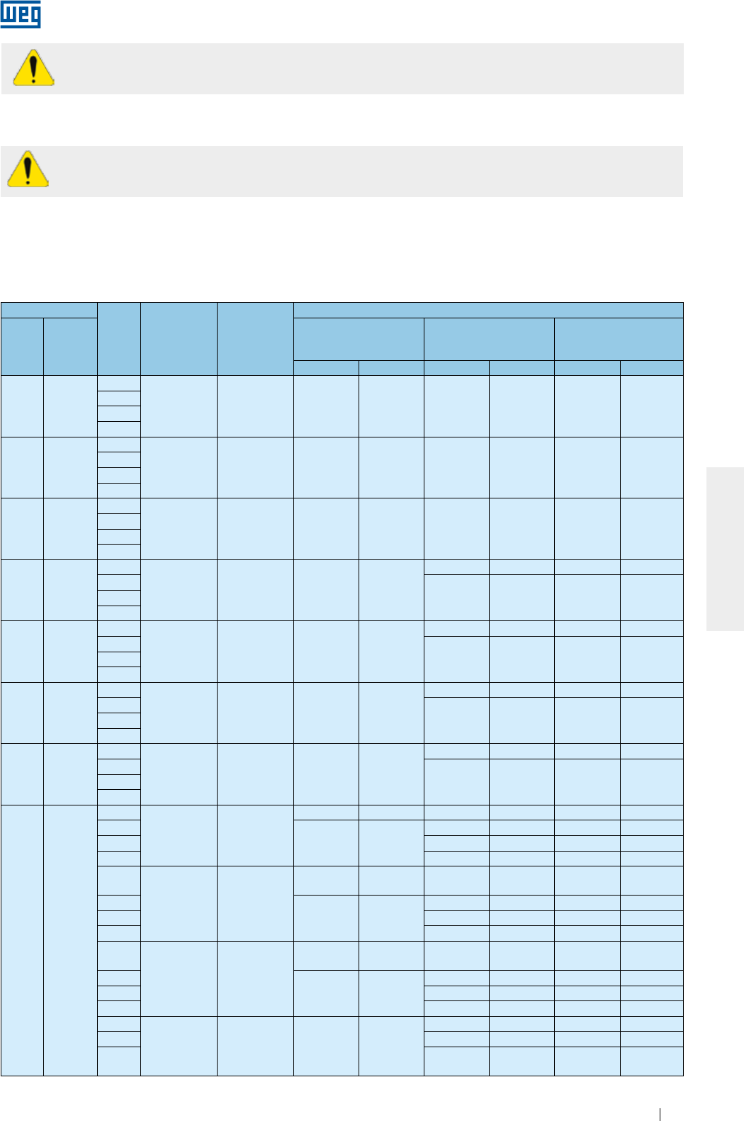
www.weg.net
Elektrische Motoren 211
DEUTSCH
Soll der Motor in Sonderumgebungen und/oder für Sonderanwendungen eingesetzt werden, bitten
wir Sie die Firma WEG anzusprechen.
Das Einpressen einer übermäßigen Fettmenge erhöht die Lagertemperatur und kann zu vorzeitigem
Lagerausfall führen.
8.2.1. Fettgeschmierte Wälzlager
Die in Tabelle 8.1, Tabelle 8.2, Tabelle 8.3 und Tabelle 8.4 angegebenen Nachschmierfristen legen für die Lager
bei horizontal aufgestellten Motoren und mit Mobil Polyrex EM Fett geschmiert, bei Bemessungsdrehzahl eine
absolute Temperatur von 70 °C (bis Baugröße IEC 200 / NEMA 324/6) und 85 °C (ab Baugröße IEC 225 /
NEMA 364/5), zugrunde. Abweichungen der o. g. Parameter müssen einzeln untersucht werden.
Tabelle 8.1 - Nachschmierfristen für Rillenkugellager
Baugröße
Polzahl Wälzlager Fettmenge
(g)
Nachschmierfristen (Std.)
IEC NEMA
Durchzugsbelüftete
Motoren (offen)
W21
Oberflächengekühlte
Motoren (geschl.)
W22
Oberflächengekühlte
Motoren (geschl.)
50 Hz 60 Hz 50 Hz 60 Hz 50 Hz 60 Hz
90 143/5
2
6205 4 - - 20000 20000 25000 25000
4
6
8
100 -
2
6206 5 - - 20000 20000 25000 25000
4
6
8
112 182/4
2
6207/
6307 9 - - 20000 20000 25000 25000
4
6
8
132 213/5
2
6308 11 - -
20000 18400 25000 23200
4
20000 20000 25000 250006
8
160 254/6
2
6309 13 20000 20000
18100 15700 22000 20000
4
20000 20000 25000 250006
8
180 284/6
2
6311 18 20000 20000
13700 11500 17000 14000
4
20000 20000 25000 250006
8
200 324/6
2
6312 21 20000 20000
11900 9800 15000 12000
4
20000 20000 25000 250006
8
225
250
280
315
355
364/5
404/5
444/5
445/7
447/9
L447/9
504/5
5008
5010/11
586/7
588/9
2
6314 27
18000 14400 4500 3600 5000 4000
4
20000 20000
11600 9700 14000 12000
6 16400 14200 20000 17000
8 19700 17300 24000 20000
2
6316 34
14000 *Auf
Anfrage 3500 *Auf
Anfrage 4000 *Auf
Anfrage
4
20000 20000
10400 8500 13000 10000
6 14900 12800 18000 16000
8 18700 15900 20000 20000
2
6319 45
9600 *Auf
Anfrage 2400 *Auf
Anfrage 3000 *Auf
Anfrage
4
20000 20000
9000 7000 11000 8000
6 13000 11000 16000 13000
8 17400 14000 20000 17000
4
6322 60 20000 20000
7200 5100 9000 6000
6 10800 9200 13000 11000
8 15100 11800 19000 14000
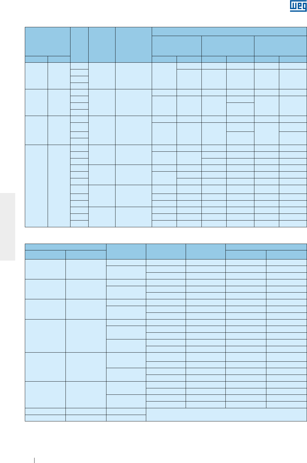
www.weg.net
Elektrische Motoren212
DEUTSCH
Tabelle 8.2- Nachschmierfristen für Zylinderrollenlager
Baugröße Polzahl Wälzlager Fettmenge (g)
Nachschmierfristen (Std.)
Durchzugsbelüftete
Motoren (offen)
W21
Oberflächengekühlte
Motoren (geschl.)
W22
Oberflächengekühlte
Motoren (geschl.)
IEC NEMA 50 Hz 60 Hz 50 Hz 60 Hz 50 Hz 60 Hz
160 254/6
2
NU309 13 20000
19600 13300 9800 16000 12000
4
20000 20000 20000 25000 250006
8
180 284/6
2
NU311 18
18400 12800 9200 6400 11000 8000
4
20000 20000 20000
19100
25000 250006 20000
8
200 324/6
2
NU312 21
15200 10200 7600 5100 9000 6000
4
20000 20000 20000
17200
25000
21000
620000 25000
8
"225
250
280
315
355"
364/5
404/5
444/5
445/7
447/9
L447/9
504/5
5008
5010/11
586/7
588/9
4
NU314 27
17800 14200 8900 7100 11000 9000
620000 20000 13100 11000 16000 13000
8 16900 15100 20000 19000
4
NU316 34
15200 12000 7600 6000 9000 7000
620000 19000 11600 9500 14000 12000
8 20000 15500 13800 19000 17000
4
NU319 45
12000 9400 6000 4700 7000 5000
6 19600 15200 9800 7600 12000 9000
8 20000 20000 13700 12200 17000 15000
4
NU322 60
8800 6600 4400 3300 5000 4000
6 15600 11800 7800 5900 9000 7000
8 20000 20000 11500 10700 14000 13000
Tabelle 8.3 - Nachschmierfristen für Rillenkugellager - Reihe HGF
Baugröße Polzahl Wälzlager Fettmenge (g) Nachschmierfristen (Stunden)
IEC NEMA 50 Hz 60 Hz
315L/A/B u.
315C/D/U.
5006/7/8T u.
5009/10/11T
2 6314 27 3100 2100
4 - 8 6320 50 4500 4500
6316 34 4500 4500
355L/A/B u.
355C/D/U.
5807/8/9T u.
5810/11/12T
2 6314 27 3100 2100
4 - 8 6322 60 4500 4500
6319 45 4500 4500
400L/A/B u. 400
C/D/U.
6806/7/8T u.
6809/10/11T
2 6315 30 2700 1800
4 - 8 6324 72 4500 4500
6319 45 4500 4500
450 7006/10
2 6220 31 2500 1400
46328 93 4500 3300
6322 60 4500 4500
6 - 8 6328 93 4500 4500
6322 60 4500 4500
500 8006/10
46330 104 4200 2800
6324 72 4500 4500
6 - 8 6330 104 4500 4500
6324 72 4500 4500
500 8006/10
46330 104 4200 2800
6324 72 4500 4500
6 - 8 6330 104 4500 4500
6324 72 4500 4500
560 8806/10 4 - 8 *Auf Anfrage
630 9606/10 4 - 8

www.weg.net
Elektrische Motoren 213
DEUTSCH
Tabelle 8.4 - Nachschmierfristen für Zylinderrollenlager - Reihe HGF.
Baugröße Polzahl Wälzlager Fettmenge (g) Nachschmierfristen (Std.)
IEC NEMA 50 Hz 60 Hz
315L/A/B u.
315C/D/U.
5006/7/8 u.
5009/10/11
4NU320 50 4300 2900
6 - 8 4500 4500
355L/A/B u.
355C/D/U.
5807/8/9 u.
5810/11/12
4NU322 60 3500 2200
6 - 8 4500 4500
400L/A/B u.
400C/D/U.
6806/7/8 u.
6809/10/11
4NU324 72 2900 1800
6 - 8 4500 4500
450 7006/10
4
NU328 93
2000 1400
6 4500 3200
8 4500 4500
500 8006/10
4
NU330 104
1700 1000
6 4100 2900
8 4500 4500
560 8806/10 4NU228 + 6228 75 2600 1600
6 - 8 106 4500 4500
630 9606/10
4
NU232 + 6232
92 1800 1000
6 120 4300 3100
8 140 4500 4500
Sollten die vorgegebenen Grenztemperaturen von 70 °C bzw. 85 °C um jeweils 15 °C überschritten werden,
sind die Nachschmierfristen zu halbieren.
Auch für horizontal hergestellte Motoren, die in vertikaler Position (nur mit Genehmigung durch die Firma WEG)
betrieben werden dürfen, muss die Nachschmierfrist halbiert werden.
Für den Einsatz von Motoren mit besonderen Bedingungen, wie: niedrige oder hohe Temperaturen, aggressive
Umgebungen, Drehzahländerungen (Speisung über Frequenzumrichter), usw. muss die Firma WEG
angesprochen werden, um Informationen über die Fettsorte und Nachschmierfristen zu erhalten.
8.2.1.1. Lager ohne Nachschmiereinrichtung
Motoren mit Lagern ohne Nachschmiervorrichtung müssen gemäß dem empfohlenen und vorbeugenden
Wartungsplan geschmiert werden. Der Lageraus- und Einbau muss gemäß Pkt. 8.3. vorgenommen werden.
Abgedichtete Lager (z. B., ZZ, DDU, 2RS, VV) sind auf Lebensdauer geschmiert und werden nach Ablauf der
vorgesehenen Lebensdauer gewechselt.
8.2.1.2. Lager mit Nachschmiereinrichtung
Das Nachschmieren der Lager muss im Stillstand des Motors wie folgt vorgenommen werden:
gDie Schmiernippel und das Umfeld sind gründlich vor jedem Nachschmiervorgang zu reinigen;
g
Nur die Hälfte, der auf dem Leistungsschild angegebenen Fettmenge, einbringen. Danach den Motor
ungefähr eine Minute bei max. Drehzahl laufen lassen;
g
Den Motor abschalten und die noch fehlende Fettmenge einpressen, um die angegebene Fettmenge zu
erreichen;
gWieder die Schmiernippel-Schutzkappen aufsetzen.
Das Nachschmieren von Lagern während des Betriebes muss wie folgt vorgenommen werden:
gDie Schmiernippel und das Umfeld sind gründlich vor jedem Nachschmiervorgang zu reinigen;
gDie auf dem Leistungsschild angegebenen Fettmengen sind einzupressen;
gWieder die Schmiernippel-Schutzkappen aufsetzen.
Zum Nachschmieren ist immer der Einsatz einer Handpresse empfohlen.
Ist der Motor mit einer Federvorrichtung zur Entfernung des Altfettes versehen, muss die Maschine so lange
betrieben werden, bis das überschüssige Fett vollkommen durch die Auslassöffnung über die Federvorrichtung
ausgestoßen worden ist.
8.2.1.3. Verträglichkeit des Fettes Mobil Polyrex EM mit anderen Fetten
Das Schmierfett der Mobil Polyrex EM Serie besitzt Mineralöl und Polyharnstoffverdicker und ist mit anderen
Fetten, die folgende Zusammensetzung haben, verträglich:
g
Verdicker auf Lithium-Basis, oder Lythium-Complex als Verdicker, oder mit Polyharnstoffverdicker und
hochraffinierte Mineralöle;
g
Die angewandten Schmierfette müssen in ihrer Formulierung Schutz vor Rost und Korrosion enthalten.
Obwohl das Schmierfett der Mobil Polyrex EM Serie mit den o. g. Fettsorten verträglich ist, ist von einer
Mischung mit anderen Fettsorten abzuraten.
Ist der Einsatz einer anderen Fettsorte erforderlich, bitten wir Sie die Firma WEG anzusprechen.
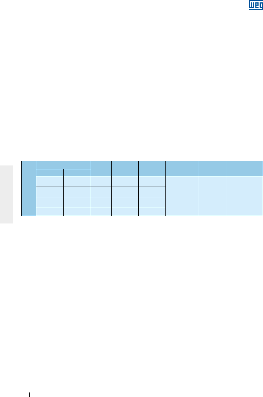
www.weg.net
Elektrische Motoren214
DEUTSCH
Tabelle 8.5 - Schmiereigenschaften des Schmieröles für vertikal aufgestellte Motoren der Reihe HGF (hohe Radialkräfte)
8.2.2. Ölgeschmierte Wälzlager
Der Ölwechsel von Motoren mit ölgeschmierten Wälzlagern muss im Stillstand wie folgt, vorgenommen werden:
g
Den Schraubstopfen von der Öleinfüllöffnung entfernen;
g
Den Schraubstopfen von der Ölablassbohrung entfernen;
g
Das Ventil öffnen und das Öl komplett vom Lager ablassen;
g
Das Ventil schließen;
g
Den Schraubstopfen wieder einschrauben;
g
Die auf dem Leistungsschild vorgegebene Ölsorte bis zur angegebenen Sichtglashöhe einfüllen;
g
Der Ölstand muss sich auf halber Sichtglashöhe befinden;
g
Den Schraubstopfen der Öleinfüllöffnung wieder eindrehen;
g
Sicherstellen, dass alle Verbindungen abgedichtet und alle nicht benutzten Gewindebohrungen mit
Schraubstopfen verschlossen sind;
Der Ölwechsel muss gemäß der auf dem Leistungsschild angegebenen Frist, oder immer dann, wenn
Änderungen an den Öleigenschaften festgestellt werden (Viskosität des Öles und seinen pH-Wert, usw.),
vorgenommen werden.
Der Ölstand muss sich auf halber Sichtglashöhe befinden.
Der Einsatz von anderen Ölviskositäten muss vorher bei der Firma WEG abgeklärt werden.
Bemerkung: Die vertikal aufgestellten Motoren der Reihe HGF mit hohen Axialkräften werden mit
fettgeschmiertem Lager an der Antriebsseite und mit ölgeschmiertem Lager an der Nichtantriebsseite geliefert.
Das antriebsseitige Lager muss nach den Nachschmieranweisungen in Pkt. 8.2.1. gewartet werden. Die Tabelle
8.5 gibt die Nachschmieranweisungen für das nichtantriebsseitige Lager (ölgeschmierte Lager) wieder.
Vertikale Aufstellung
Baugröße Polzahl Wälzlager Ölmenge (l)
Max.
Betriebsdauer
(Std.)
Ölmarke Öleigenschaften
IEC NEMA
315L/A/B u.
315C/D/U.
5006/7/8T u.
5009/10/11T 4 - 8 29320 20
8000
Renolin
DTA 40 /
SHC 629
Mineralöl ISO
VG150 mit
Antischaum- und
Antioxidations-
mittel
355L/A/B u.
355C/D/U.
5807/8/9T u.
5810/11/12T 4 - 8 29320 26
400L/A/B u.
400C/D/U.
6806/7/8T u.
6809/10/11T 4 - 8 29320 37
450 7006/10 4 - 8 29320 45
8.2.3. Schmierölnebel geschmierte Wälzlager
Den Zustand der Dichtungen überprüfen und wenn ein Austausch erforderlich ist, immer Originaldichtungen
verwenden. Vor dem Zusammenbau müssen alle Bauteile gründlich gereinigt werden (Lagerdeckel,
Lagerschilde, usw.). Zwischen den Auflageflächen der Lagerdeckel und Lagerschilde nur Dichtungsmittel
auftragen, die mit dem verwendeten Öl verträglich sind.
Die Verbindungen des Öleintritts- und Austritts und dem Ölablasssystems müssen gemäß Bild 6.12
vorgenommen werden.
8.2.4. Gleitlager
Der Ölwechsel von Gleitlagern muss gemäß der in Tabelle 8.6 angegebenen Fristen wie folgt vorgenommen
werden:
gnichtantriebsseitiges Lager: Inspektionsdeckel von der Lüfterhaube entfernen;
gDas Öl über die Ölablassbohrung am unteren Teil des Lagergehäuses komplett ablassen (siehe Bild 8.1);
gDie Ölablassbohrung mit dem Schraubstopfen wieder verschließen;
gDen Schraubstopfen von der Öleinfüllöffnung entfernen;
gDie vorgegebene Ölmenge unter Beachtung der Ölsorte einfüllen;
gDer Ölstand muss sich auf halber Sichtglashöhe befinden;
gDie Öleinfüllöffnung mit dem Schraubstopfen wieder verschließen;
gSicherstellen, dass alle Verbindungen abgedichtet sind.

www.weg.net
Elektrische Motoren 215
DEUTSCH
Öleinfüllöffnung
Ölablassbohrung
Sichtglas
Bild 8.1 - Gleitlager
Tabelle 8.6 - Schmiereigenschaften des Schmieröles für Gleitlager
Baugröße
Polzahl Wälzlager Ölmenge (l)
Max.
Betriebsdauer
(Std.)
Ölmarke Öleigenschaften
IEC NEMA
315L/A/B u.
315C/D/E
5006/7/8T u.
5009/10/11T
2 9-80 2.8 8000 Renolin
DTA 10
Mineralöl ISO
VG32 mit
Antischaum- und
Antioxidations-mittel
355L/A/B u.
355C/D/E
5807/8/9T u.
5810/11/12T
400L/A/B u.
400C/D/E
6806/7/8 u.
6809/10/11T
450 7006/10
315L/A/B u.
315C/D/E
5006/7/8T u.
5009/10/11T
4 - 8
9-90
2.8
8000 Renolin DTA
15
Mineralöl ISO
VG46 mit
Antischaum- und
Antioxidations-mittel
355L/A/B u.
355C/D/E
5807/8/9T u.
5810/11/12T 9-100
400L/A/B u.
400C/D/E
6806/7/8 u.
6809/10/11T 11-110
4.7
450 7006/10 11-125
500 8006/10
Der Ölwechsel muss gemäß der auf dem Leistungsschild angegebenen Frist, oder immer wenn Änderungen an
den Öleigenschaften festgestellt werden (Ölviskosität und seinen pH-Wert, usw.), vorgenommen werden.
Der Ölstand muss sich auf halber Sichtglashöhe befinden.
Der Einsatz von anderen Ölviskositäten muss vorher bei WEG geklärt werden.
8.3. DEMONTAGE UND MONTAGE
Es wird vorausgesetzt, dass nur qualifizierte Personen für die Demontage, Montage und Wartung
an diesen Maschinen unter Beachtung der einschlägigen Normen und Richtlinien des betreffenden
Landes, beauftragt werden. Zur Demontage und Montage des Motors immer geeignete Werkzeuge
und Vorrichtungen verwenden.
Demontage- und Montagearbeiten dürfen nur nach Abschalten und Stillstand der Maschine
vorgenommen werden.
Auch nach dem Ausschalten des Motors, können an den Klemmen im Klemmenkasten noch
gefährliche Spannungen anliegen. Es könnte sein, dass eine Stillstandsheizung oder eine Beheizung über
die Wicklung noch in Betrieb ist. Auch wenn der Motor vom Netz getrennt ist, können vorhandene
Kondensatoren noch aufgeladen sein. Deshalb niemals die Kondensatoren und/oder die Klemmen des
Motors berühren bevor nicht sichergestellt ist, dass sie komplett entladen sind.
Motoren, die über Frequenzumrichter betrieben werden, können auch nach dem Stillstand des Motors
noch gefährliche Spannungen führen.
Vor dem Beginn der Demontagearbeiten, wird empfohlen die zuständigen Installationsbedingungen, wie den
Anschluss der Versorgungskabel an die Motorklemmen, die Ausrichtung / Nivellierung, usw. genau
aufzuzeichnen, da die künftige Montage nach diesen Aufzeichnungen gemacht werden muss.
Bei der Demontage ist mit großer Sorgfalt ohne harte Hammerschläge vorzugehen, um Beschädigungen an
bearbeiteten Oberflächen und/oder Gewinden zu vermeiden.
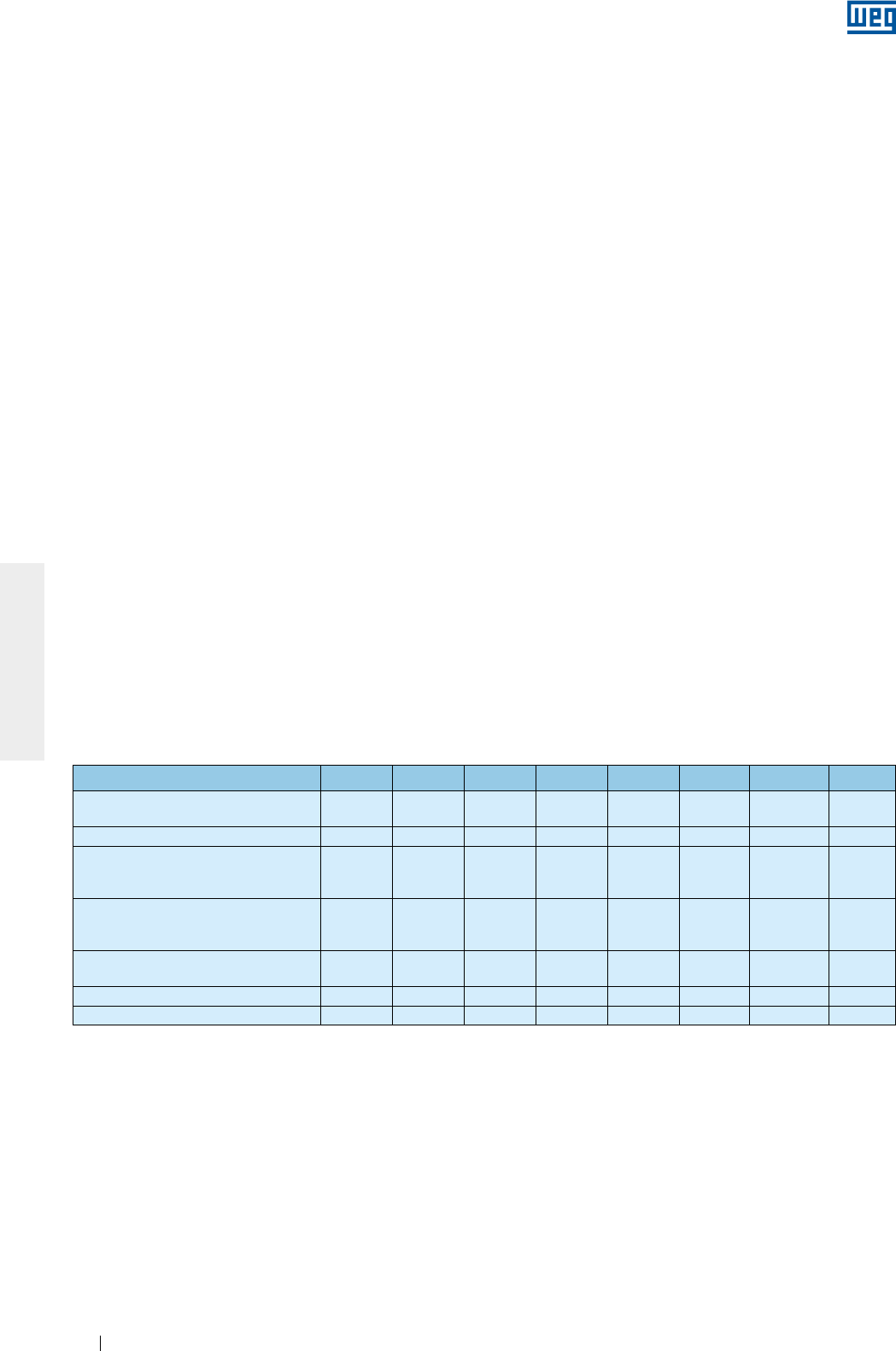
www.weg.net
Elektrische Motoren216
DEUTSCH
Um eine sichere Auflage des Motors zu gewährleisten, ist der Motor immer auf eine sichere und ebene Fläche
abzustellen. Motoren ohne Füße müssen immer mit Klötzen abgestützt werden, um Unfälle zu vermeiden.
Besondere Sorgfalt soll den isolierten, spannungsführenden Bauteilen, z. B. Wicklungen, isolierte Wälzlager,
Versorgungskabeln, usw., gewidmet werden, um Beschädigungen an den Isoliermaterialien zu vermeiden.
Dichtungselemente, z.B. Dichtungen im Klemmenkasten und Lagerdichtungen müssen gewechselt werden,
sobald sie einen Verschleiß oder Beschädigungen aufweisen.
Motoren mit höherem Schutzgrad als IP55 werden in den Fugen und an den Schrauben mit einer flüssigen
Dichtung Loctite 5923 (Henkel) abgedichtet, geliefert. Nach einer Demontage des Motors sind vor der Montage,
die Oberflächen gründlich zu reinigen und einen neuen Film dieser Dichtung aufzutragen.
8.3.1. Klemmenkasten
Zur Entfernung des Klemmenkastendeckels, um Zugang zur den Klemmen/Anschlüssen der Versorgungs- und
Zubehörkabel zu bekommen, muss mit äußerster Sorgfalt wie folgt vorgegangen werden:
g
Während der Schraubenentfernung sicherstellen, dass der Klemmenkastendeckel nicht die im
Klemmenkasten eingebauten Bauteile beschädigt;
g
Ist der Klemmenkastendeckel mit einer Transportöse versehen, muss diese zum Transport des
Klemmenkastendeckels benutzt werden;
g
Werden Motoren mit Klemmenbrett geliefert, muss sichergestellt werden, das ihre Schrauben mit den in
Tabelle 8.7 angegebenen Drehmomenten angezogen sind;
g
Sicherstellen, dass die Kabel nicht mit scharfen Kanten in Kontakt kommen;
g
Mit großer Sorgfalt darauf achten, dass der auf dem Leistungsschild des Motors angegebene Schutzgrad
strikt eingehalten wird. Für die Bauteile (Kabelverschraubungen und Kabelrohre, usw.) der Versorgungs- und
Zubehörkabel sind immer die einschlägigen Normen und Sicherheitsvorschriften des betreffenden Landes zu
befolgen;
g
Sicherstellen, dass die Druckentlastungsvorrichtungen, wenn vorhanden, sich immer in einem guten
Betriebszustand befinden. Die Dichtungen des Klemmenkastens müssen vor dem Neueinbau auf
Beschädigungen überprüft werden und müssen den, auf dem Leistungsschild des Motors angegebenen
Schutzgrad, strikt einhalten. Beschädigte Bauteile müssen gegen neue WEG-Originalteile ausgetauscht
werden;
g
Überprüfen und sicherstellen, dass die Schraubenverbindungen mit dem in Tabelle 8.7 angegebenen
Anziehdrehmoment angezogen wurden.
Tabelle 8.7 - Anziehdrehmomente der Befestigungsschrauben [Nm]
Schraubentyp und Dichtung M4 M5 M6 M8 M10 M12 M16 M20
Sechskantschraube / Inbusschraube
(ohne Dichtung) - 4 - 7 7 - 12 16 - 30 30 - 50 55 - 85 120 - 180 230 -
360
Kreuzschlitzschraube (ohne Dichtung) - 3 - 5 5 - 10 10 - 18 - - - -
Sechskantschraube / Inbusschraube
(Dichtung mit metallischem Anschlag/
Gummidichtring)
- - - 13 - 20 25 - 37 40 - 55 50 - 65 -
Kreuzschlitzschraube(mit
Flachdichtung und/oder metallischem
Anschlag/Gummidichtring)
- 3 - 5 4 - 8 8 - 15 - - - -
Sechskantschraube / Inbusschraube
(mit Flachdichtring) - - - 8 - 15 18 - 30 25 - 40 35 - 50 -
Klemmenbrett 1 - 1,5 1,5 - 4 3 - 6,5 6 - 9 10 - 18 15,5 - 30 30 - 50 -
Erdungsklemmschraube - 3 - 5 5 - 10 10 - 18 30 - 50 55 - 85 120 - 180 -
8.4. MINDESTISOLATIONSWIDERSTAND UND EVTL. TROCKNUNG DER WICKLUNG
Der Isolationswiderstand der Wicklung muss in regelmäßigen Abständen gemessen werden. Unterschreitet der
Isolationswiderstand die vorgegebenen Werte, ist die Motorwicklung zunächst auf Feuchtigkeit und
Schmutzablagerungen zu überprüfen. Wenn erforderlich, muss die Motorwicklung gereinigt und anschließend
in einem Trockenofen getrocknet werden. Das Trocknungsverfahren muss wie folgt vorgenommen werden:
Den Motor komplett demontieren. Die Lüfterhaube, evtl. auch den Lüfter, Lagerschilde abbauen und den
kompletten Läufer (mit Welle) ausbauen. Anschließend muss noch der Klemmenkasten abgebaut werden. Nur
das Gehäuse mit der Ständerwicklung darf in einem Trockenofen gelagert werden. Die Temperatur ist
allmählich bis max. 200 ºC zu erhöhen und mindestens zwei Stunden zu halten. Werden größere Motoren
getrocknet, kann eine längere Trockenzeit erforderlich sein. Nach dem Trocknungsverfahren den Motor auf
Raumtemperatur abkühlen lassen und die Isolationswiderstandsmessung gemäß 5.4 wiederholen. Wird der
Mindestisolationswiderstand nicht erreicht, kann ein wiederholtes Trocknungsverfahren notwendig sein. Wenn
nach dem Trocknungsverfahren die Werte des Isolationswiderstandes nicht ansteigen, müssen die Ursachen
gesucht und evtl. eine Neuwicklung des Ständers in Betracht gezogen werden.
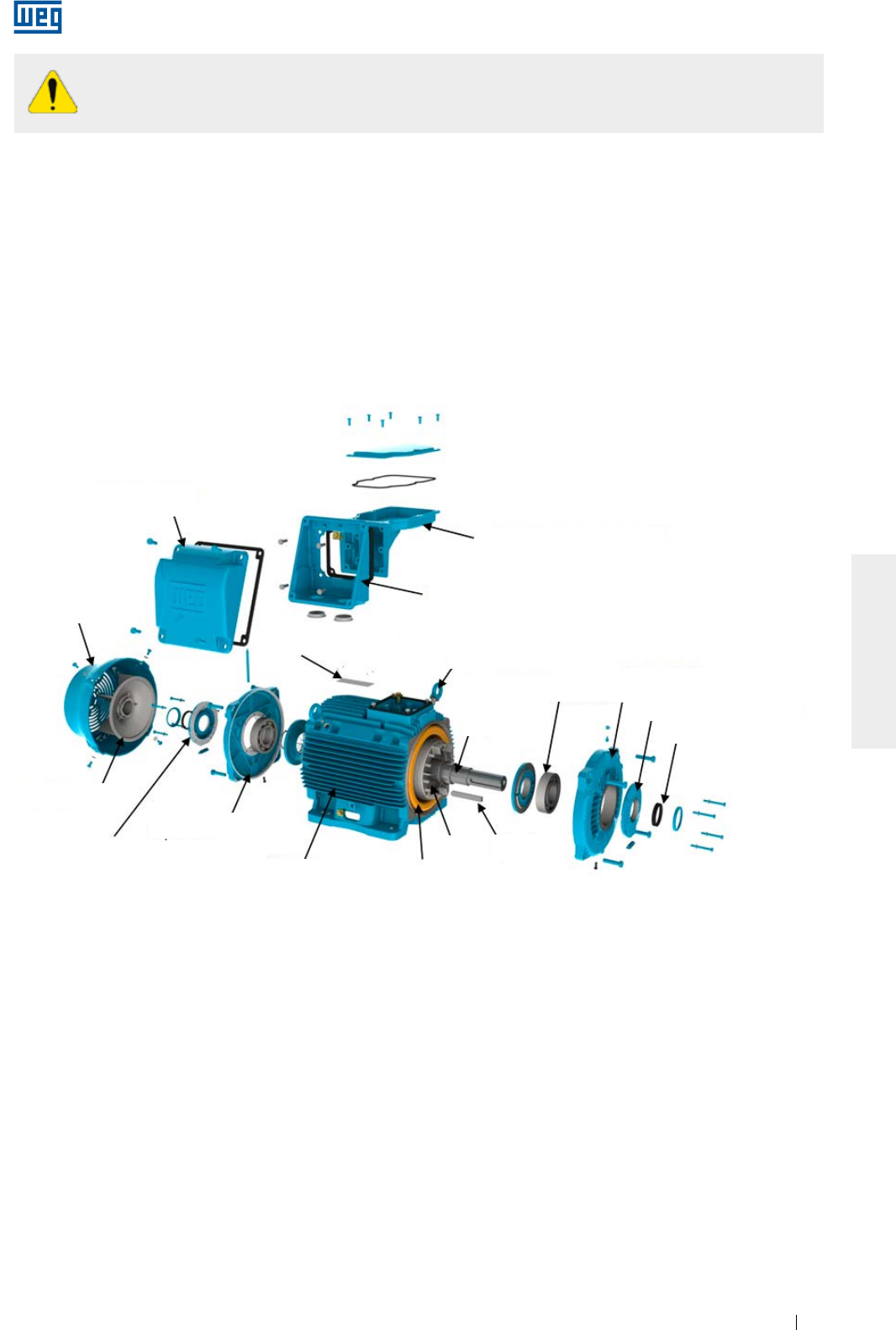
www.weg.net
Elektrische Motoren 217
DEUTSCH
Um einen elektrischen Schock zu vermeiden, müssen die Motorklemmen vor und nach jeder
Messung geerdet werden. Erden Sie die Kondensatoren (falls geliefert) um Ihre komplette
Entladung zu erlauben bevor Sie die Messung vornehmen.
8.5. ERSATZTEILE
Bei der Bestellung von Ersatzteilen, bitte folgende Informationen mitteilen:
Motortyp, Seriennummer der Maschine, Bezeichnung des Ersatzteiles.
Der Motortyp und die Seriennummer der Maschine sind auf dem Leistungsschild angegeben.
Es wird empfohlen nur Ersatzteile von WEG zugelassener Vertriebsstellen zu beziehen. Der Einsatz von nicht
Originalbauteilen kann die Betriebseigenschaften beeinflussen, einen Motorausfall zur Folge haben und die
Gewährleistung aufheben.
Die Ersatzteile müssen in einem sauberen, trockenen, staub-, gas- und schwingungsfreien Ort (Raum), ohne
Vorhandensein von aggressiven Chemikalien, bei einer relativen Luftfeuchtigkeit unter 60 % und in einem
Temperaturbereich zwischen 5 º und 40 ºC gelagert werden.
Bild 8.2 - Explosionszeichnung der Bauteile des Motors der Baureihe W22
Klemmenkastendeckel
Klemmenkastenhalter
Klemmenkastenuntersatz
Leistungsschild
Klemmenkastendeckel
Lagerdeckel, Antriebsseite
Lagerdichtung- Antriebsseite
Lagerdeckel,
Nichtantriebsseite
Lüfter
Lagerschild,
Nichtantriebsseite
Gehäuse Gewickelter Ständer
Läufer Passfeder
Welle
Wälzlager
Lüfterhaube
Lagerschild, Antriebsseite

www.weg.net
Elektrische Motoren218
DEUTSCH
9. INFORMATION ÜBER DEN UMWELTSCHUTZ
9.1. VERPACKUNGEN
Die elektrischen Motoren werden in Karton- Kunststoff oder Holzverpackungen geliefert. Dieses Material ist
recycelbar und kann der Wiederverwendung zugeführt werden. Die gültigen Vorschriften und Richtlinien des
betreffenden Landes müssen beachtet werden. Das für die Verpackung von WEG-Motoren verwendete Holz
stammt aus der Wiederaufforstung und wurde nicht chemisch zur Erhaltung behandelt.
9.2. PRODUKT
Von den Konstruktionseigenschaften her gesehen, werden elektrische Motoren hauptsächlich aus Eisenmetalle
(Stahl und Eisen), Nichteisenmetalle (Kupfer und Aluminium) und Kunststoff hergestellt.
Allgemein kann man sagen, dass der Elektromotor eine lange Lebensdauer aufweist. Aber wenn es sich um
Entsorgung von Elektromotoren handelt, empfehlen wir, das Material der Verpackung und die Materialien des
Motors ordnungsgemäß zu trennen und zur korrekten Entsorgung und Wiederverwendung zu schicken. Die
nicht recycelbaren Materialien müssen ordnungsgemäß nach den gültigen Gesetzen und Richtlinien des
betreffenden Landes entweder auf Werksdeponien deponiert, oder in Müllverbrennungsanlagen, die von den
Umweltbehörden des betreffenden Landes genehmigt sind, verbrannt werden.
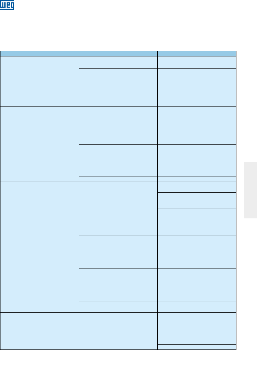
www.weg.net
Elektrische Motoren 219
DEUTSCH
10. STÖRUNGSSUCHE UND BEHEBUNG
Die nachstehende Tabelle gibt eine Auflistung von Fehlern, möglicher Ursachen und Maßnahmen wieder.
Im Zweifelfall bitte WEG Máquinas ansprechen.
Fehler Mögliche Ursache Maßnahme
Motor startet nicht (auch nicht im Leerlauf)
Spannungsversorgung ist unterbrochen Stromkreis und Motorversorgungskabel
überprüfen
Sicherungen verbrannt Sicherungen wechseln
Fehlerhafte Netzanschlüsse Netzanschlüsse gemäß Schaltbild vornehmen
Blockiertes Lager Überprüfen, ob sich das Lager frei drehen lässt
Motor startet im Leerlauf, startet aber nicht unter
Last, oder startet nur sehr langsam und erreicht
nicht die max. Drehzahl
Lastmoment zu hoch beim Start Maschine nicht mit Bemessungslast starten
Zu hoher Spannungsabfall in den
Versorgungskabeln
Bemessung der Installation überprüfen
(Transformatoren, Kabelquerschnitt, Relais,
Lasttrennschalter, usw.)
Ungewöhnliches Geräusch
Defektive Übertragungselemente zwischen
Antriebsmaschine und angetriebener Maschine
Kraftübertragung, Kupplungsausrichtung/
Nivellierung überprüfen
Basis nicht genau ausgerichtet/
nivelliert
Motor und angetriebene Maschine genau
ausrichten/nivellieren
Bauteile der Antriebsmaschine oder der
angetriebenen Maschine nicht ausreichend
ausgewuchtet
Motor und angetriebene Maschine neu
auswuchten
Verschiedene Auswuchtmethoden für Motor und
Kupplungen verwendet (halbe, volle Passfeder) Neu auswuchten
Drehsinn nicht korrekt Den Anschluss von 2 Phasen untereinander
tauschen
Lose Befestigungsschrauben Die Befestigungsschrauben neu nachziehen
Fundamentresonanz Das Projekt des Fundaments überprüfen
Beschädigtes Lager Beschädigtes Lager auswechseln
Ständerwicklung erwärmt sich stark
Nicht ausreichende Kühlung
Lufteintritts- und Austrittsöffnung der Lüfterhaube
und das Gehäuse reinigen
Mindestabstand zwischen der Lüfterhaube und
den nächstliegenden Wänden überprüfen Siehe
Pkt. 6
Die Kühlluft am Eingang messen
Überlast Ständerstrom messen, die Einsatzbedingungen
überprüfen und evtl. die Last vermindern
Zu viele Anläufe pro Stunde, Trägheitsmoment zu
hoch Anläufe pro Stunde reduzieren
Versorgungsspannung zu hoch
Die Versorgungsspannung überprüfen. Nicht den
höchst zugelassenen Wert in Pkt. 7.2
überschreiten
Versorgungsspannung zu niedrig
Versorgungsspannung und Spannungsabfall
überprüfen. . Nicht den höchst zugelassenen
Wert in Pkt. 7.2 überschreiten
Versorgungskabel unterbrochen Verbindungen der Versorgungskabel überprüfen
Spannungsasymmetrie an den
Motorversorgungsklemmen
Funktionsprüfung der Sicherungen ,
falsche Steuerungen der Sicherungen,
Spannungsasymmetrie der
Versorgungsspannung, Phasenausfall oder
Unterbrechung der Versorgungskabel überprüfen
Motordrehrichtung stimmt nicht mit der
Drehrichtung des Lüfters überein
Die Drehrichtung mit dem auf dem Lüfter
angegeben Pfeil überprüfen
Zu hohe Erwärmung des Wälzlagers
Zu viel Schmierfett/Schmieröl
Die Drehrichtung mit dem auf dem Lüfter
angegeben Pfeil überprüfen
Schmierfett/Schmieröl veraltet und verhärtet
Nicht angegebenes Schmierfett/Schmieröl
eingesetzt
Es fehlt Schmierfett/Schmieröl Das Lager nach den Anweisungen schmieren
Zu hohe axiale oder radiale Last auf die Welle Riemenspannung reduzieren
Die angetriebene Last neu bemessen

www.weg.net
Elektrische Motoren220
DEUTSCH
11. GEWÄHRLEISTUNG
WEG Equipamentos Elétricos S.A., Division Motores (“WEG”), bietet für ihre Produkte auf Herstellungs- und
Materialfehlern eine Gewährleistungsfrist von 18 (achtzehn) Monaten nach Rechnungslegung im Werk oder von
unserer Vertriebsniederlassung, bzw. Händler, beschränkt auf max. 24 Monate nach Herstellungsdatum.
Gewährleistungsfrist für die Motoren der Baureihe HGF beträgt 12 (zwölf) Monate nach Rechnungslegung im
Werk oder von unserer Vertriebsniederlassung, bzw. Händler, beschränkt auf max. 18 Monate nach
Herstellungsdatum.
Die o.g. Absätze legen die rechtlichen Gewährleistungsfristen fest.
Wurde im Liefervertrag eine andere Gewährleistungsfrist für eine bestimmte Lieferung vereinbart, so ersetzt
diese die oben genannten Fristen.
Die o.g. Gewährleistungsfristen hängen nicht von dem Einbau- und von dem Inbetriebnahmedatum ab.
Werden Abweichungen von dem normalen Betrieb des Produktes festgestellt, muss der Herstellungsfehler vom
Käufer unverzüglich an WEG schriftlich mitgeteilt werden und die Maschine muss der Firma WEG oder einer
von WEG zugelassenen Reparaturwerkstatt (Kundendienststelle) ausreichend lange zur Verfügung stehen, um
die Ursachen dieser Abweichung zu identifizieren, die Gewährleistung zu überprüfen, sowie die
entsprechenden Reparaturen vorzunehmen.
Um ein Anrecht auf die Gewährleistung zu haben, muss der Käufer die Angaben in den technischen WEG-
Dokumenten, hauptsächlich die in der Installations-, Betriebs- und Wartungsanleitung des Produktes und die
einschlägigen Normen und Sicherheitsvorschriften des betreffenden Landes erfüllen.
Ausgeschlossen von der Gewährleistung sind Fehler, die ihre Ursache in nicht ordnungsgemäßem Einsatz und
Betrieb der Maschine, oder wegen Unterlassung der vorgeschriebenen vorbeugenden Wartung, als auch
wegen Fehler durch äußere Faktoren wie z.B. der Einsatz von Geräten und Bauteilen, die nicht von WEG
geliefert wurden.
Die Garantie wird ungültig, wenn der Kunde auf eigene Initiative, Reparaturen und/oder Änderungen am Gerät
vorgenommen hat, ohne dass eine vorherige schriftliche Zustimmung der Firma WEG eingeholt wurde.
Ausgeschlossen von der Gewährleistung sind Ausrüstungen, Bau- und Einzelteile sowie Materialien, deren
Lebensdauer geringer, als die Gewährleitungsfrist ist. Die Gewährleistung ist auch dann ungültig, wenn Mängel
und/oder Probleme, die auf höhere Gewalt oder andere Ursachen zurückzuführen sind und die nicht auf die
Firma WEG bezogen werden können. Als mögliche Beispiele wären unvollständige Spezifikationen mit falschen
Daten seitens des Käufers, der den Transport, die Lagerung, die Handhabung, und die Installation, sowie den
Betrieb und die vorgegebene Wartung nicht in Übereinstimmung mit den mitgelieferten Anweisungen beachtet
hat. Auch Unfälle, Mängel an Zivilarbeiten, für Anwendungen und/oder Umgebungen, für die das Produkt nicht
ausgelegt wurde, Geräte und/oder Bauteile, die nicht im WEG-Lieferumfang enthalten sind. Die Gewährleistung
beinhaltet keine Demontagedienste in den möglichen Einrichtungen des Kunden, ebenso wenig Transport- und
Anfahrtskosten des Produktes und die Reise- Unterkunfts- und Verpflegungskosten des technischen
Personals, falls diese vom Kunden gefordert wurde.
Die unter die Gewährleistung fallenden Dienste werden ausschließlich in WEG genehmigten Werkstätten oder
im Herstellerwerk durchgeführt. Die Reparatur oder der Ersatz von mangelhaften Bauteilen verlängert auf
keinen Fall die Gewährleistungsfristen.
Die Zivilhaftung der Firma WEG beschränkt sich auf das gelieferte Produkt. Die Firma WEG ist nicht haftbar für
Personenschäden, Schäden an Dritte, Schäden anderer Ausrüstungen oder anderen Anlagen,
verlorengegangene Gewinne oder anderer auftretende oder daraus entstandene Schäden, die sich aus dem
Vertrag der Parteien ergeben.

www.weg.net
Elektrische Motoren 221
DEUTSCH
12. EG-KONFORMITÄTSERKLÄRUNG
WEG Equipamentos Elétricos S/A
Av. Prefeito Waldemar Grubba, 3000
89256-900 - Jaraguá do Sul – SC – Brasilien,
und ihr zugelassener Vertreter mit Niederlassung in der Europäischen Gemeinschaft,
WEGeuro – Industria Electrica SA
Kontaktperson: Luís Filipe Oliveira Silva Castro Araújo
Rua Eng Frederico Ulrich, Apartado 6074
4476-908 – Maia – Porto – Portugal
erklären hiermit in alleiniger Verantwortung, dass:
WEG Asynchronmotoren und die Bauteile dieser Motoren:
Drehstrom
Baugrößen IEC 63 bis 630
Baugrößen NEMA 42, 48, 56 und 143 bis 9610
...............
Einphasig
Baugrößen IEC 63 bis 132
Baugrößen NEMA 42, 48, 56 und 143 bis 215
...............
wenn die Motoren richtig installiert, gewartet und für das entsprechende Einsatzgebiet eingesetzt werden, für die sie
entwickelt wurden, erfüllen sie unter Berücksichtigung der Einbaunormen und der Anweisungen des Herstellers, die
Anforderungen folgender europäischer Richtlinien und Normen, wenn anwendbar:
Richtlinien:
Richtlinie 2006/95/EG -Niederspannungsrichtlinie*
Verordnung (EG) Nr. 640/2009*
Richtlinie 2009/125/EG*
Maschinenrichtlinie 2006/42/EG**
Richtlinie-2004/108/EG - Elektromagnetische Verträglichkeit (EMV) (Asynchronmotoren halten die technischen
Anforderungen der EMV- Richtlinie ein.)
Normen:
EN 60034-1:2010/ EN 60034-2-1:2007/EN 60034-5:2001/A1:2007/ EN 60034-6:1993/ EN 60034-7:1993/A1:2001/
EN 60034-8:2007/ EN 60034-9:2005/A1:2007/ EN 60034-11:2004/ EN 60034-12:2002/A1:2007/
EN 60034-14:2004/A1:2007/ EN 60034-30:2009, EN 60204-1:2006/AC:2010 und EN 60204-11:2000/AC:2010
EG-Kennzeichnung in: 1996
* Die Elektromotoren für eine Nennspannung über 1000 V ausgelegt, sind nicht durch die o.g. Richtlinien abgedeckt.
** Die Niederspannungsmotoren für eine Nennspannung bis 1000 V ausgelegt, sind nicht durch die o.g.
Maschinenrichtlinie abgedeckt. Die Elektrische Motoren für eine Nennspannung über 1000 V ausgelegt, werden als
unvollständige Maschinen betrachtet und werden mit einer
Einbauerklärung geliefert:
Die Inbetriebnahme der oben bezeichneten Erzeugnisse ist solange untersagt, bis die Maschine, in die diese
Erzeugnisse eingebaut werden, als konform mit den Bestimmungen der Maschinenrichtlinie erklärt wurde.
Die Technische Dokumentation für die oben genannten Erzeugnisse wurde gemäß Teil B des Anhangs VII der
Maschinenrichtlinie 2006/42/EG erarbeitet.
Die Technische Dokumentation für die oben genannten Erzeugnisse wurde gemäß Teil B des Anhangs VII der
Maschinenrichtlinie 2006/42/EG erarbeitet und kann auf Anfrage von Nationalbehörden an WEG zugelassenen
Vertreter aus der Europäischen Gemeinschaft herbeigebracht werden. Die Übermittlung von Informationen kann
physisch als auch in elektronischer Form vorgenommen werden. Alle Urheberrechte des Herstellers sind vorbehalten.
Milton Oscar Castella
Engineeringdirektor
Jaraguá do Sul, den 8. April 2013

WEG Worldwide Operations
Cod: 50033244 | Rev: 07 | Date (m/y): 06/2013
The values shown are subject to change without prior notice.
WEG Worldwide Operations
Grupo WEG - Motors Business Unit
Jaraguá do Sul - SC - Brazil
Phone: +55 47 3276 4000
motores@weg.net
www.weg.net
For those countries where there is not a WEG own operation, find our local distributor at www.weg.net.
ARGENTINA
WEG EQUIPAMIENTOS
ELECTRICOS
San Francisco - Cordoba
Phone: +54 3564 421 484
info-ar@weg.net
www.weg.net/ar
WEG PINTURAS - Pulverlux
Buenos Aires
Phone: +54 11 4299 8000
tintas@weg.net
AUSTRALIA
WEG AUSTRALIA
Victoria
Phone: +61 3 9765 4600
info-au@weg.net
www.weg.net/au
AUSTRIA
WATT DRIVE - WEG Group
Markt Piesting - Viena
Phone: +43 2633 404 0
watt@wattdrive.com
www.wattdrive.com
BELGIUM
WEG BENELUX
Nivelles - Belgium
Phone: +32 67 88 84 20
info-be@weg.net
www.weg.net/be
BRAZIL
WEG EQUIPAMENTOS ELÉTRICOS
Jaraguá do Sul - Santa Catarina
Phone: +55 47 3276-4002
info-br@weg.net
www.weg.net/br
CHILE
WEG CHILE
Santiago
Phone: +56 2 784 8900
info-cl@weg.net
www.weg.net/cl
CHINA
WEG NANTONG
Nantong - Jiangsu
Phone: +86 0513 8598 9333
info-cn@weg.net
www.weg.net/cn
COLOMBIA
WEG COLOMBIA
Bogotá
Phone: +57 1 416 0166
info-co@weg.net
www.weg.net/co
FRANCE
WEG FRANCE
Saint Quentin Fallavier - Lyon
Phone: +33 4 74 99 11 35
info-fr@weg.net
www.weg.net/fr
GERMANY
WEG GERMANY
Kerpen - North Rhine Westphalia
Phone: +49 2237 9291 0
info-de@weg.net
www.weg.net/de
GHANA
ZEST ELECTRIC GHANA
WEG Group
Accra
Phone: +233 30 27 664 90
info@zestghana.com.gh
www.zestghana.com.gh
INDIA
WEG ELECTRIC INDIA
Bangalore - Karnataka
Phone: +91 80 4128 2007
info-in@weg.net
www.weg.net/in
WEG INDUSTRIES INDIA
Hosur - Tamil Nadu
Phone: +91 4344 301 501
info-in@weg.net
www.weg.net/in
ITALY
WEG ITALIA
Cinisello Balsamo - Milano
Phone: +39 02 6129 3535
info-it@weg.net
www.weg.net/it
JAPAN
WEG ELECTRIC MOTORS
JAPAN
Yokohama City - Kanagawa
Phone: +81 45 550 3030
info-jp@weg.net
www.weg.net/jp
MEXICO
WEG MEXICO
Huehuetoca
Phone: +52 55 5321 4231
info-mx@weg.net
www.weg.net/mx
VOLTRAN - WEG Group
Tizayuca - Hidalgo
Phone: +52 77 5350 9354
www.voltran.com.mx
NETHERLANDS
WEG NETHERLANDS
Oldenzaal - Overijssel
Phone: +31 541 571 080
info-nl@weg.net
www.weg.net/nl
PERU
WEG PERU
Lima
Phone: +51 1 472 3204
info-pe@weg.net
www.weg.net/pe
PORTUGAL
WEG EURO
Maia - Porto
Phone: +351 22 9477705
info-pt@weg.net
www.weg.net/pt
RUSSIA and CIS
WEG ELECTRIC CIS
Saint Petersburg
Phone: +7 812 363 2172
info-ru@weg.net
www.weg.net/ru
SOUTH AFRICA
ZEST ELECTRIC MOTORS
WEG Group
Johannesburg
Phone: +27 11 723 6000
info@zest.co.za
www.zest.co.za
SPAIN
WEG IBERIA
Madrid
Phone: +34 91 655 30 08
info-es@weg.net
www.weg.net/es
SINGAPORE
WEG SINGAPORE
Singapore
Phone: +65 68589081
info-sg@weg.net
www.weg.net/sg
SCANDINAVIA
WEG SCANDINAVIA
Kungsbacka - Sweden
Phone: +46 300 73 400
info-se@weg.net
www.weg.net/se
UK
WEG ELECTRIC MOTORS U.K.
Redditch - Worcestershire
Phone: +44 1527 513 800
info-uk@weg.net
www.weg.net/uk
UNITED ARAB EMIRATES
WEG MIDDLE EAST
Dubai
Phone: +971 4 813 0800
info-ae@weg.net
www.weg.net/ae
USA
WEG ELECTRIC
Duluth - Georgia
Phone: +1 678 249 2000
info-us@weg.net
www.weg.net/us
ELECTRIC MACHINERY
WEG Group
Minneapolis - Minnesota
Phone: +1 612 378 8000
www.electricmachinery.com
VENEZUELA
WEG INDUSTRIAS VENEZUELA
Valencia - Carabobo
Phone: +58 241 821 0582
info-ve@weg.net
www.weg.net/ve
