18183 3 Grundfos 91128530 Product Guide User Manual
18197 3 Grundfos 91128531 Product Guide 18197_3_Grundfos 91128531 Product Guide
18202 3 Grundfos 91128533 Product Guide 18202_3_Grundfos 91128533 Product Guide
18214 3 Grundfos 91128528 Product Guide 18214_3_Grundfos 91128528 Product Guide 18214_3_Grundfos 91128528 Product Guide pdf pumpproducts
User Manual: Pump 18183 3 Grundfos 91128530 Product Guide
Open the PDF directly: View PDF ![]() .
.
Page Count: 58
GRUNDFOS PRODUCT GUIDE
Domestic Water Supply Family
DWS Product Guide 8-09.indd 1 8/18/2009 2:32:25 PM

Domestic Water Supply Family Table of Contents
Applications Page No.
• Constantpressure............................................................ 5
• Flowbasedpressureboosting...................................... 5
• Suctionlift...........................................................................6
• Rainwaterharvesting......................................................6
Pump Selections
• EZBoost..............................................................................6
• MQ.........................................................................................6
• BasicLineJets....................................................................6
Accessories
• PressureTanks.................................................................... 7
• PressureSwitches.............................................................. 7
• Valves................................................................................... 7
– Check......................................................................... 7
– Foot............................................................................ 7
– Shut-off...................................................................... 7
– FlowControl............................................................. 7
– PressureReducing................................................... 7
– PressureRelief.......................................................... 7
Theory
Matchingconsumptionandpumpcapacity................... 7
Pumpselection....................................................................... 7
Piping......................................................................................... 7
Trouble Shooting
Suctionlift................................................................................8
Floodedsuction.......................................................................8
PressureTanks........................................................................9
WebCAPS..................................................................................9
EZBoost...................................................................................12
MQ...........................................................................................28
BasicLineJets........................................................................38
Submittal Data Sheet.................................................. 57
Handbook
Product Guides
2
DWS Product Guide 8-09.indd 2 8/18/2009 2:32:25 PM
Domestic Water Supply Handbook
Handbook Domestic Water Supply Handbook
DWS Product Guide 8-09.indd 3 8/18/2009 2:32:29 PM

Handbook Notes
4
DWS Product Guide 8-09.indd 4 8/18/2009 2:32:29 PM
Handbook Applications
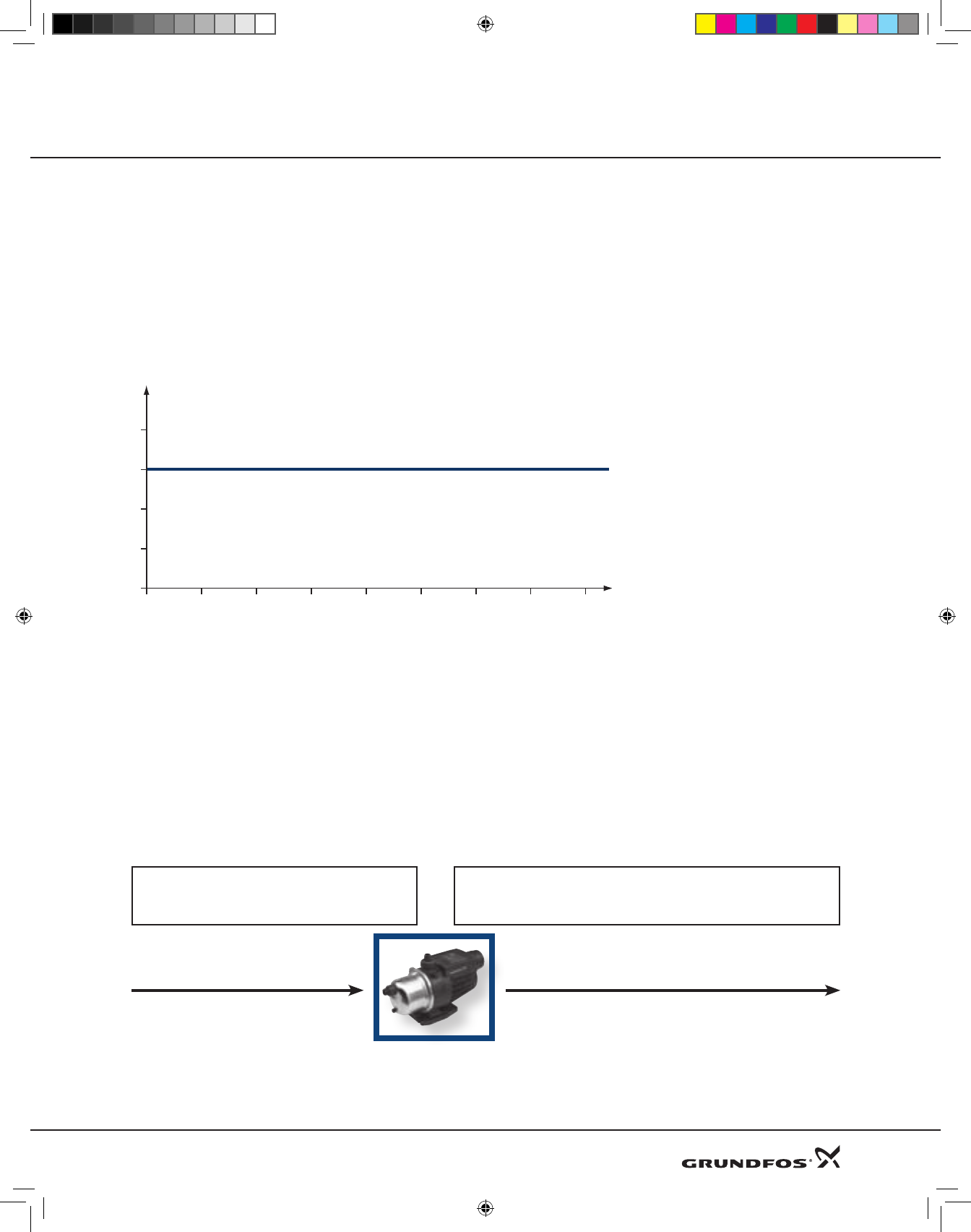
Constant Pressure System:
Inconstantwaterpressuresystems,onlytherequireddischargepressureneedssetting.Cut-in/outpressuresdonot
playaroleinthissystem.
InGrundfos’sBMQEconstantwaterpressuresystem(EZBoost),thisisdonebyasimpletouchofabuttononthe
accompanyingCU301controlunit.Dischargepressurecanbesetfrom40to100PSI,accordingtoindividualneedsand
pipingsystemlimitations.
H
Time
noitpmusnoc ot pihsnoitaler ni yrav ton seod erusserP
Flow Based Pressure Boosting:
Thepumpstartsautomaticallywhenwaterisconsumedandstopsautomaticallywhentheconsumptionceases.
Thisisaccomplishedbyaflowswitchconnectedtoaprintedcircuitboard(PCB).Theflowswitchisclosedwhen
waterisconsumedandthesignalsenttothePCBstartsthepump.Theflowswitchisopenedwhenthecon-
sumptionceasesandthesignalsenttothePCBstopsthepump.
Thepumpwillproducepressureinrelationtotheflowratewithanyincomingpressurecumulativetothetotal
dischargepressure.
Incoming PSI = City Water Pressure Outgoing PSI = Incoming PSI + MQ Performance
5
DWS Product Guide 8-09.indd 5 8/18/2009 2:32:30 PM
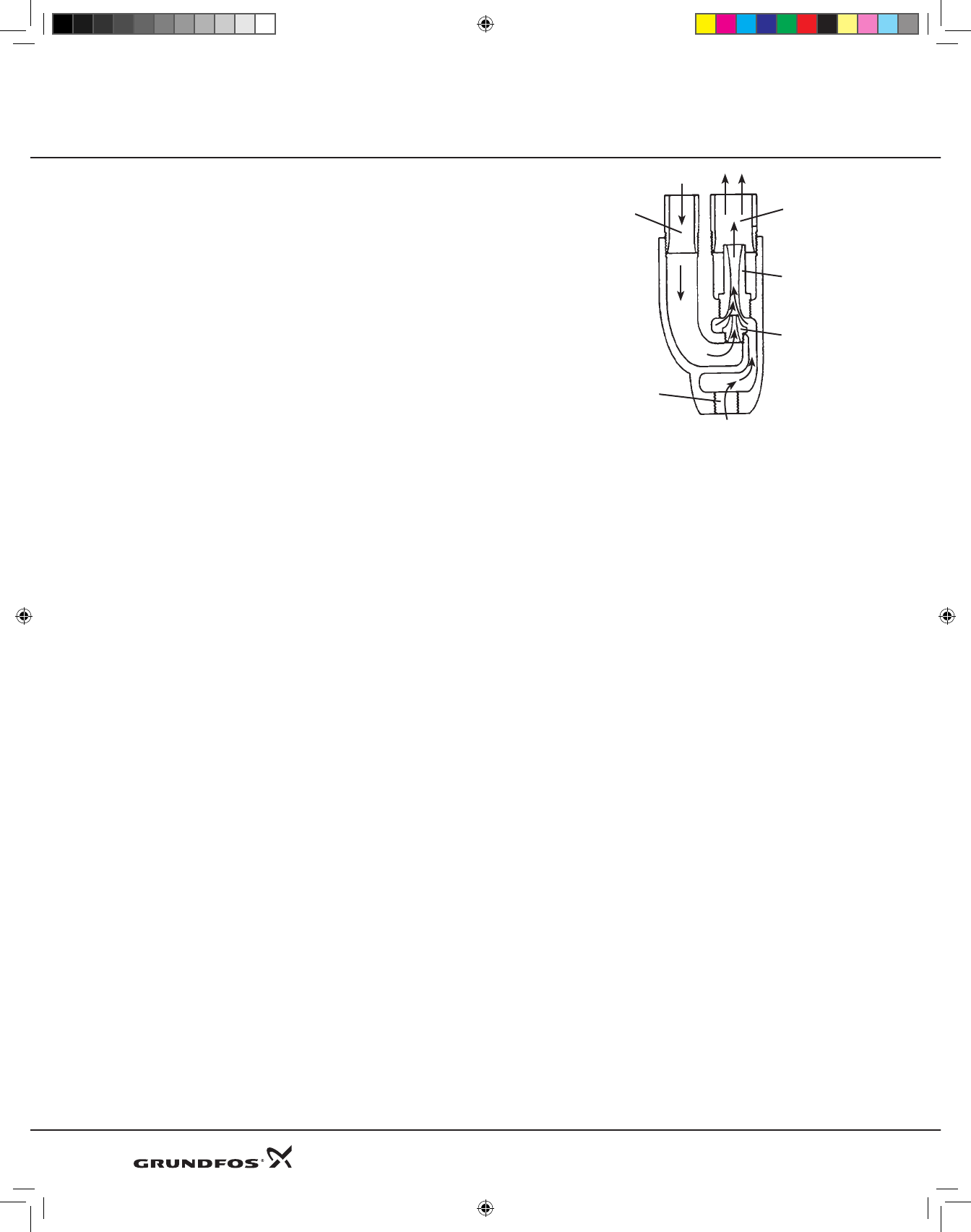
Suction Lift:
Highpressurewaterfromthedrivepipepassesthroughtheventuriandpulls
waterfromthewellintotheejector,andthenpushesituptothepump.This
allowsustopushwateruptothepumpfromdepthsgreaterthan25feet,or
toboosttheoutputfromashallowwellpumptohigherpressures.
Handbook Applications
DRIVE
PIPE
SUCTION
PIPE
VENTURI
NOZZLE
INLET
Rain Water Harvesting:
Reduce,reuse,andrecycle.TheThreeR’sofconservation.Rainwaterharvestingisthewaytostorerainwaterforfuture
usesuchasthewateringofagarden.Simplycollectrainwaterfromtheroofofyourhomethroughtheevesintoastorage
container.UsetheMQtopullasuctionlift,usinganoncollapsiblesuctionline,fromthestoragecontainertowateryour
garden.
Pump Selections:
EZ Boost: Constant Pressure at the touch of a button.
TheEZBoostusesthetimetestedtechnologyusedintheSQEconstantpressuresystem(submersibleapplication).The
MSE3motorsarebasedonsolidstateelectronicsandpermanentmagnetrotorswhichaccountforhighmotorefficiencies.
VariablespeedisofferedthoughfrequencycontrolviatheCU301remotestatusbox.TheSystemcanbesettooperateat
anydutypointintherangebetweenminimumandmaximumperformanceofthepump.TheEZBoosthasbuiltinsafeties
inthesolidstateelectronics.Thesmallfootprintofthepumpallowsthesystemtobepositionedeitherverticallyorhorizon-
tallydependingontheneedsoftheapplication.RefertotheEZBoostinstallationvideoonourwebsitewww.grundfos.us
MQ: Maximum Quality Flow Based Pressure Boosting System:
TheMQisacomplete,all-in-oneunit,incorporatingpump,motor,diaphragmtank,pressureandflowsensor,controllerand
checkvalve.Builtinsafetiesensurelonglifeofthepump.Thesesafetiesinclude:dryrunning;excessivetemperature;any
overloadconditions.TheMQisaselfprimingpumpandneedsnoprimingotherthanthatatinstallation.TheMQisaplug-
n-playsystem.
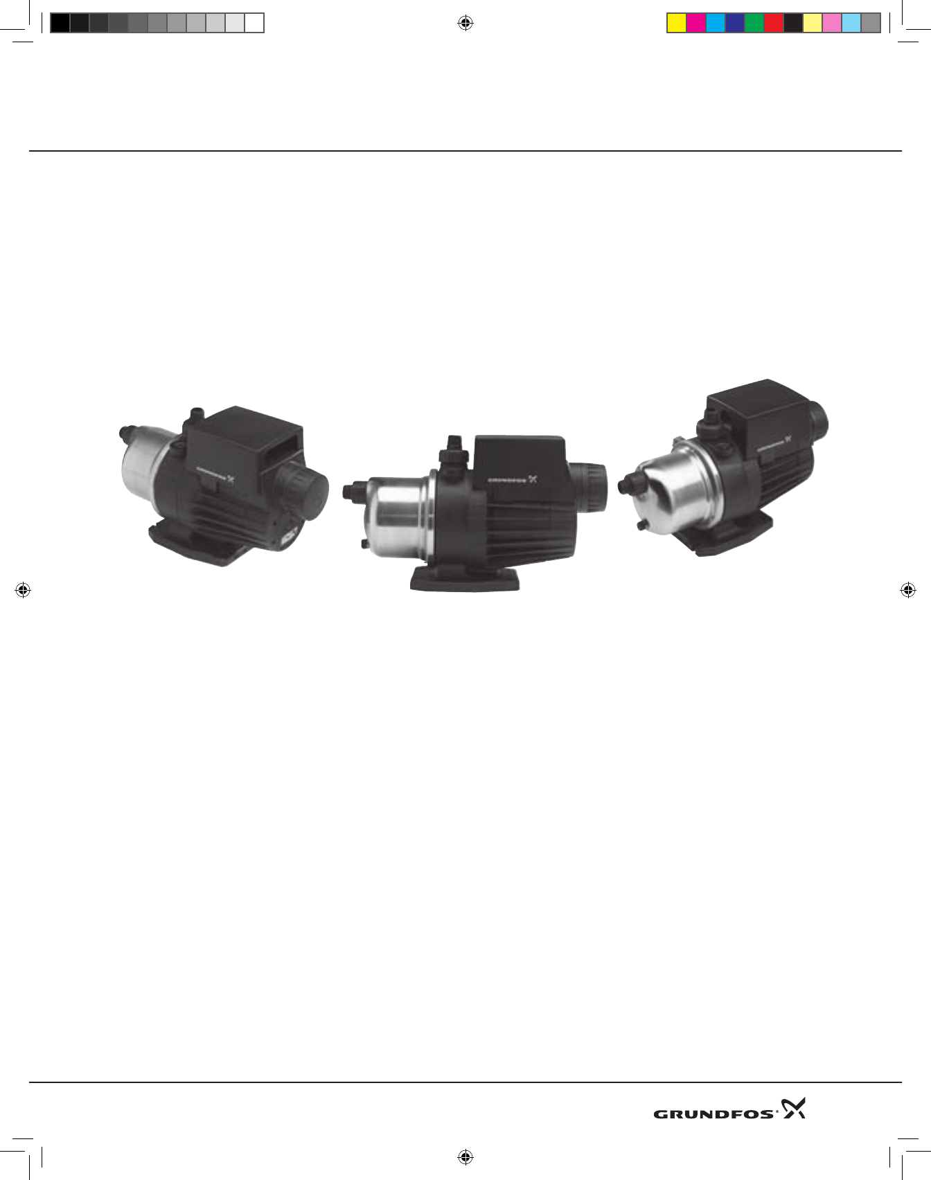
Basic Line: Durable and dependable Basic Line Jets.
Grundfosoffersshallowwell,deepwell,andconvertiblejetpumps.Ourjetsareself-primingcentrifugalpumpssuitablefor
domesticwatersupply,lightagriculture,andindustrialwatertransferapplications.Threemodelsinclude:JPS;JPF;JDF.The
JPSareshallowwelljetswithbuilt-inejectors.TheJPFareconvertiblejetswithdetachableejectorassemblyfordeepwell
applications.TheJDFaredeepwelljetswithseparatedeepwellportforconnectiontoDeepWellejectorkits.
6
DWS Product Guide 8-09.indd 6 8/18/2009 2:32:30 PM

Handbook Accessories
Pressure Tanks:
TanksareprovidedwiththeEZBoostandMQsystems.TheEZBoosthasanexternaltankandtheMQaninternaltank.The
BasicLinehowevermayneedatankdependingonyourapplication.Inordertominimizethenumberofpumpstartsand
stopsinthewatersupplysystem,andtoreduceproblemswithwaterhammerinthepipework,apressuretankshouldbe
installed.
Pressure Switches:
Pressureswitchesareusedtocontrolpumpoperation.Theseswitcheshaveacut-inpressureandacut-outpressuretoturn
thepumponandoffrespectfully.TheEZBoostcomeswithapressuretransducerforconstantpressure.TheMQhasabuilt-
inpressureswitch.BasicLineJetshavethepressureswitchattached.
Valves:
Check valves: TheEZBoostandMQsystemshavebuilt-incheckvalves.WhendoingasuctionliftwiththeMQacheck
valveisrequiredattheinlet.ThischeckvalveisprovidedwitheveryMQ.
Foot Valves:Whenpullingasuctionlift(shallowordeepwell)withtheBasicLineafootvalveisrequired.Thisvalve
isinstalledattheendofthesuctionpipetopreventbackflow.TheMQwillalsobenefitfromtheuseofafootvalve
whendoingsuctionlifts.
Shut off valves:Useshutoffvalvesinthepipingsysteminsuchawaytomakeitpossibletodrainonlythepartofthe
systemthatneedsattentionorrepair.
Flow control valves:Usedinapplicationswhereasetamountofflow(gallonsperminute)arerequired.Anexample
ofthiswouldbeashowerheadoranirrigationsystem.
Pressure reducing valves:Usedinapplicationswheretheincomingwaterpressureexceedsthemaximuminletpres-
sureofthepumpasisthecasewiththeMQandcitywaterpressure.ThePressureReducingValveorPRVisusedinline
afterthecitywatertapandbeforethepumptoensureasetpressure.
Pressure relief valves: Thisvalveisaspringcontrolleddevisethatcanbeadjustedtomeettheneedsofthepumping
system.Usedinapplicationswherehighpressurecanresultindamagetoaccessoriessuchastankswherethereare
maximumpressureratings.
Theory:
Matching consumption and pump capacity:
Selectingtherightpumpisamatterofmatchingwaterconsumptionwithpumpcapacity.Installinganunderor
oversizedpumpshouldbeavoided.Consumptionvariesgreatlydependingonhousingstandardsandlifestyle.Garden
wateringinthesummercanincreaseconsumption.
Pump Selection:
Pumpselectionisbasedonthewaterdemandandthesystemhead.Thewaterdemanddependsonthenumberof
consumersconnectedtothesystem.HeadcaneitherbeexpressedinfeetorPSI.Headreferstostatichead,pressure
head,andfrictionhead.ForassistanceinPumpSelectionrefertotheWebCAPSselectionprogramfoundonthe
Grundfoswebsite.
Piping:
Inanywatersupplysystem,thesizingandchoiceofmaterialsofthepipeworkhasanimpactonthechoiceofpumps
andonthecost.PipingtakesintoaccountthesystemheadasreferredtoinPumpSelection.Staticheadisthedistance
fromthegroundwaterleveltotheuppermosttap.Pressureheadisthesystempressurethecustomerwantstoachieve.
Inmostresidentialapplicationthispressureisapproximately60PSI.Frictionheaddependsonthepipesize,typeand
length.Whencalculatingfrictionlossalwaysremembertoallowfordeteriorationinthepipingschematicasallwater
pipeswilleventuallybecomecoatedwithrust,limedeposits,etc.Flowvelocityinthepipingmustbekeptlowasnoise
canoccurduetoturbulenceinelbowsandvalvesorfromwaterhammer.Fittingapressurereliefvalveinthedischarge
pipingisrecommendedtoprotectthepipingfromover-pressureduetosystemmalfunction.
7
DWS Product Guide 8-09.indd 7 1/8/2010 11:00:13 AM
Handbook Troubleshooting
Troubleshooting:
Suction Lift:
Wheninstallingabovegroundsuctionliftpumps,thefollowingbasicrulesmustbeadheredto:
•Avoidfrost.
•Pumponlycleanwater.
•Installafilterifwatercontainsimpurities.
•Afoot-valvemustbeinstalled.
•Thesuctionpipemustbe100%airtight.
•Thepumpmustbeprimedbeforestartingforthefirsttime.
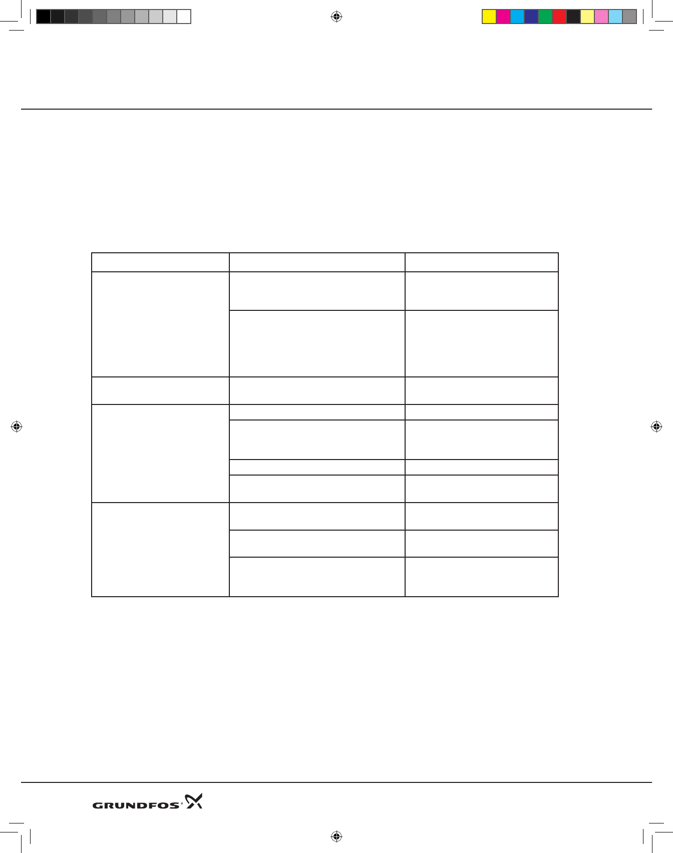
Fault Cause Remedy
1. The pump is running but
there is no pressure.
a) The pump and suction pipe
work need to be primed.
Fill the pump and pipe with
water.
b) The suction pipe is not 100% tight.
Check all connections and the
suction pipe. Replace if
necessary.
2. The pump does not stop. a) The pressure switch is set incor-
rectly.
Check the setting
and adjust accordingly
3. The pump does not deliver
enough water.
a) Lack of water in the well. Drill new well.
b) Suction pipe is not 100% tight.
Check all connections and the
suction pipe. Replace if
necessary.
c) Pipe system is blocked. Clean pipework.
d) Pump capacity is not sufficient Replace with a larger capacity
pump
4. Pump switches on and off
frequently.
a) Pre-pressure in pressure tank is too
low or too high.
Adjust pre-pressure in pressure
tank. (0,9 x cut-in pressure)
b) Faulty footvalve. Check footvalve,
replace if necessary.
c) The pressure switch differen-
tial between the start and stop
pressures is too small.
Increase the differential.
Flooded Suction:
Wheninstallingabovegroundsuctionboosterpumps,the
followingbasicrulesmustbeadheredto:
•Inletpressure.
•Avoidfrost.
•Pumponlycleanwater.
•Avoiddry-running
•Anon-returnvalvemustbeinstalled.
•Thesuctionpipemustbe100%airtight.
•Thepumpandpipingmustbeprimedbeforestarting
forthefirsttime.
8
DWS Product Guide 8-09.indd 8 8/18/2009 2:32:30 PM
Handbook Accessories
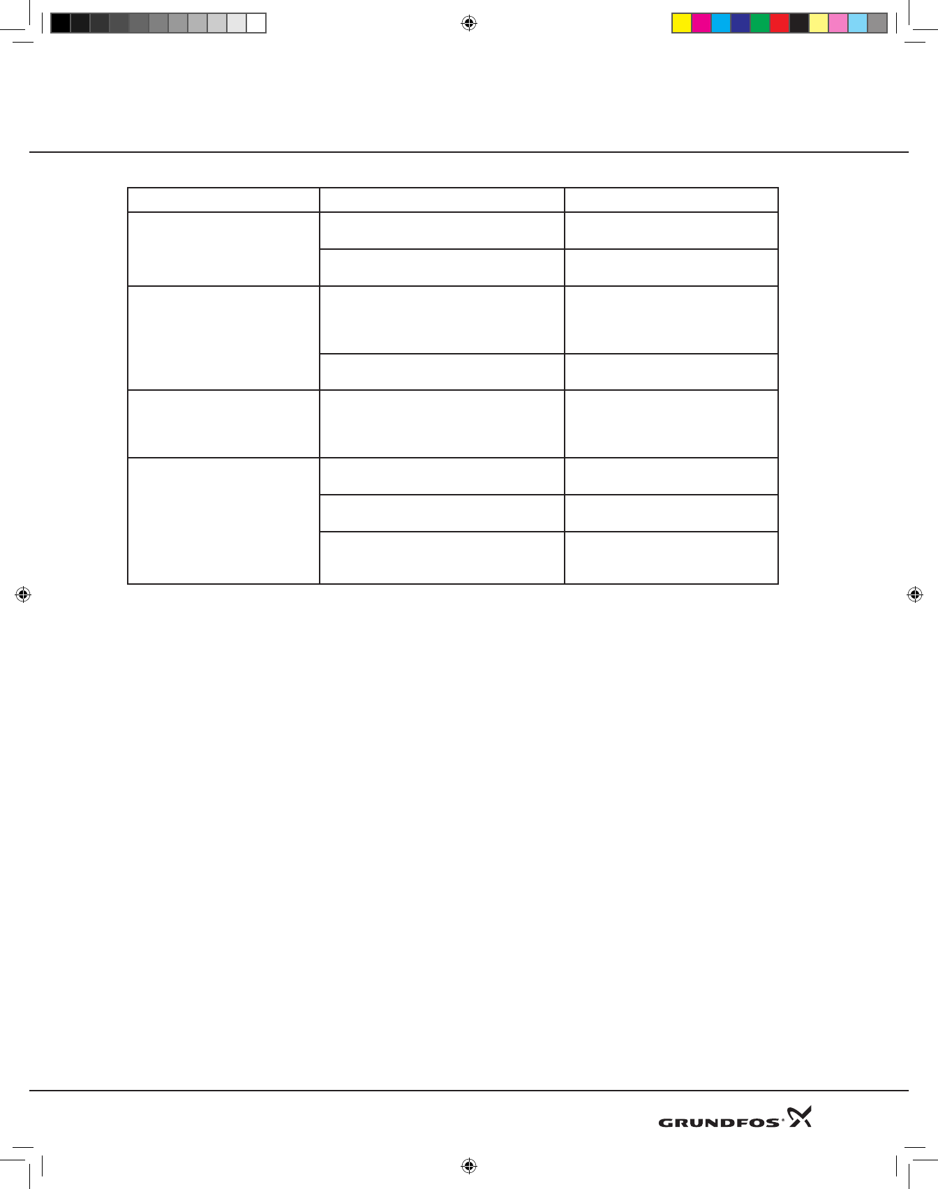
Fault Cause Remedy
5. The pump is running but
there is no pressure.
a) The pump and/or suction pipe
is incorrectly primed.
Prime the pump and/or suction
pipe with water.
b) The non-return valve or suction
pipe is leaky.
Replace the non-return valve
and/or seal the suction pipe.
6. The pump does not deliver
enough water.
a) The suction lift is too high.
Check the distance from the
pump to the water level in the
well. If possible, mount the
pump nearer the water level.
b) Pressure switch settings are incor-
rect Adjust settings accordingly
7. The pump has run for a
long time, but delivers no
water when restarted after a
standstill.
a) The pump and/or suction pipe is
emptied of water.
Prime the pump and/or suction
pipe with water.
8. Pump switches on and off
frequently.
a) Pre pressure in pressure tank is
too low or too high.
Adjust pre-pressure in pressure
tank. (0,9 x cut-in pressure)
b) Faulty foot valve. Check footvalve, replace if nec-
essary.
c) The pressure switch differential
between the start and stop pressures
is too small.
Increase the differential.
Pressure Tanks:
Keepthefollowingtipsinmind,whendealingwithinstallationsusingpressuretanks:
•Stopthepumpandopenavalvetorelievethewaterpressurebeforecheckingthepre-chargepressureof
thetank.
•Fortraditionalon/offcontrolledpumps,thepre-chargepressureshouldequalthecut-inpressuremultipliedby0.9.
Installation note:
YoushouldalwaysconsulttheInstructionandOperationmanualforeachspecificpumpduringinstallationandstart.
WebCAPS:
FinddetailedinformationviatheGrundfoswebsite.WebCAPSisaneasytouseon-linetoolthatenablesusers
tosizesystemsandaccessgeneralinformationaboutourproducts,whereyoucaneasilydownloadthemost
up-todatepumpinformation.
9
DWS Product Guide 8-09.indd 9 8/18/2009 2:32:31 PM

DWS Product Guide 8-09.indd 10 8/18/2009 2:32:31 PM
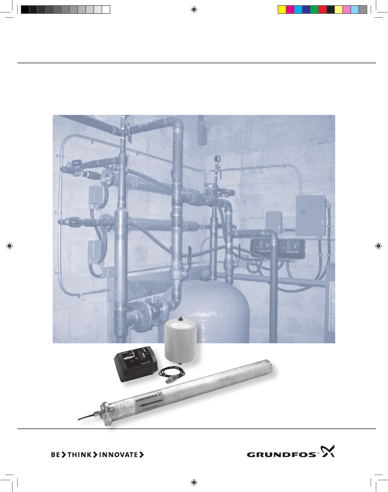
EZ BoostTM System with BMQE Booster Pump,
Tank, Pressure Sensor, and Controller
Product Guide EZ Boost™ System
DWS Product Guide 8-09.indd 11 8/18/2009 2:32:32 PM

Product Guide Page No.
Generaldata 13
Productrange 14
Materialsofconstruction 15
Typekey 15
15BMQEperformancecurves 16
22BMQEperformancecurves 17
30BMQEperformancecurves 18
Dimensions,weightsandelectricaldata 19
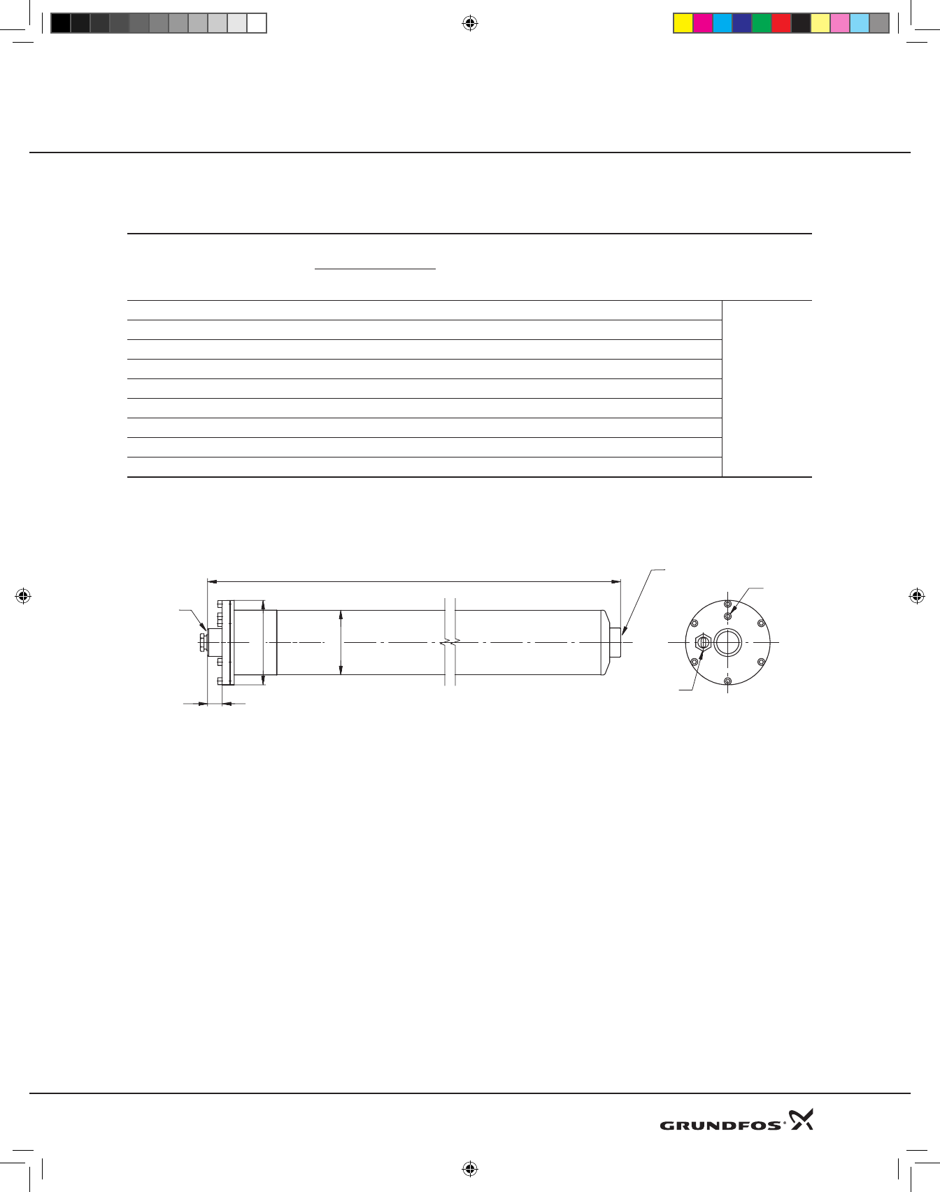
Dimensionalsketch 19
Technicaldata-BMQEpump 20
Technicaldata-EZBoostcontroller 21
Accessories 22
EZBoostQuickGuide 23
EZBoostSystemDiagram 23
EZBoostPre-Installation 24
ParallelOperation 25
Contents EZ BoostTM System
12
DWS Product Guide 8-09.indd 12 8/18/2009 2:32:33 PM
EZ BOOST SYSTEM
Introduction
Therearemanyapplicationswithinwatersupplywhereit
isnecessarytoincreasethesystempressure.TheGrundfos
EZBoostsystemistheoptimumsolutionforapplications
requiring:
•Seallesspumps
•Quietoperationand/or
•Maintenance-freeoperation.
TheEZBoostsystemoffersthefollowingfeatures:
•Dry-runningprotection
•Highefficiencyofpumpandmotor
•Excellentwearresistance
•Softstarter
•Overvoltageandundervoltageprotection
•Overloadprotection
•Overtemperatureprotection.
•Variablespeed
•Electroniccontrolandcommunication.
Applications
•Pressureboosting.
•Watertreatment.
Pumped liquids
Thin, non-explosive liquids not containing abrasive par-
ticlesor fibers.The liquidmust notbe ableto attackthe
pumpmaterialschemicallyormechanically.
Shouldthedensityand/orviscosityofthepumpedliquid
exceedthe densityand/or viscosityof water,please con-
tactGrundfos.
BMQE Pump
The pumps used for The Grundfos EZ Boost system are
modified SQE submersible pumps. The EZ Boost BMQE
pump is an SQE pump with an MSE 3 motor. Pump and
motorarecenteredinthe4”stainlesssteelsleeve.
BMQEpumpsaresuitable for both continuousandinter-
mittentoperationforavarietyofpressureboostingappli-
cations.
BMQE Motor
TheMSE3motorsarebasedonstate-of-the-arttechnology
within permanent magnets (PM motor), which accounts
for the high motor efficiencies. In addition, the motors
havea built-inelectronicunitwithafrequencyconverter
forvariablefrequencyandsoftstarting.
Product Guide EZ BoostTM System
TheMSE 3 motors features highefficiency within a wide
load range. The high and flat efficiency curve of the PM
motor enables the same motor to cover a wide power
range as opposed to conventional AC motors. For BMQE
pumps,thismeansfewermotorvariants.
EZ Boost Controller
TheBMQEpumpfeaturesvariablespeedwhichisoffered
throughfrequencycontrolviatheEZBoostcontroller.Asa
consequence,thepumpcanbesettooperateinanyduty
pointin therangebetweentheminimumandmaximum
performancecurvesofthepump.EachBMQEpumpmust
beconnectedtoitsownEZBoostcontroller.
ItisalsopossibletooperatetheBMQEwithoutanEZBoost
controller,thoughthefeaturesofferedwillbefewer.
Operating conditions
Flow: Max.39USGPM(8.9m3/h)
Head: Max.300ft(91.4m)
Temperature: Max.95°F(35°C)
Operatingpressure: Max.347PSI(23bar)
Inletpressure: Min.8PSI(0.55bar)
Sound-pressurelevel: Thesoundpressurelevelofthe
BMQE is lower than 74 db[A] at a distance of 3 feet (1
meter).
It is recommended by Grundfos that the pump be installed
with sound and vibration dampening equipment such as
flexible piping adapters and anti-vibration mounting. The
pump should not be mounted in or adjacent to living quar-
ters. The pump can also be wrapped with sound- proofing
insulation to reduce noise (see page 16, EZ Boost System
Diagram).
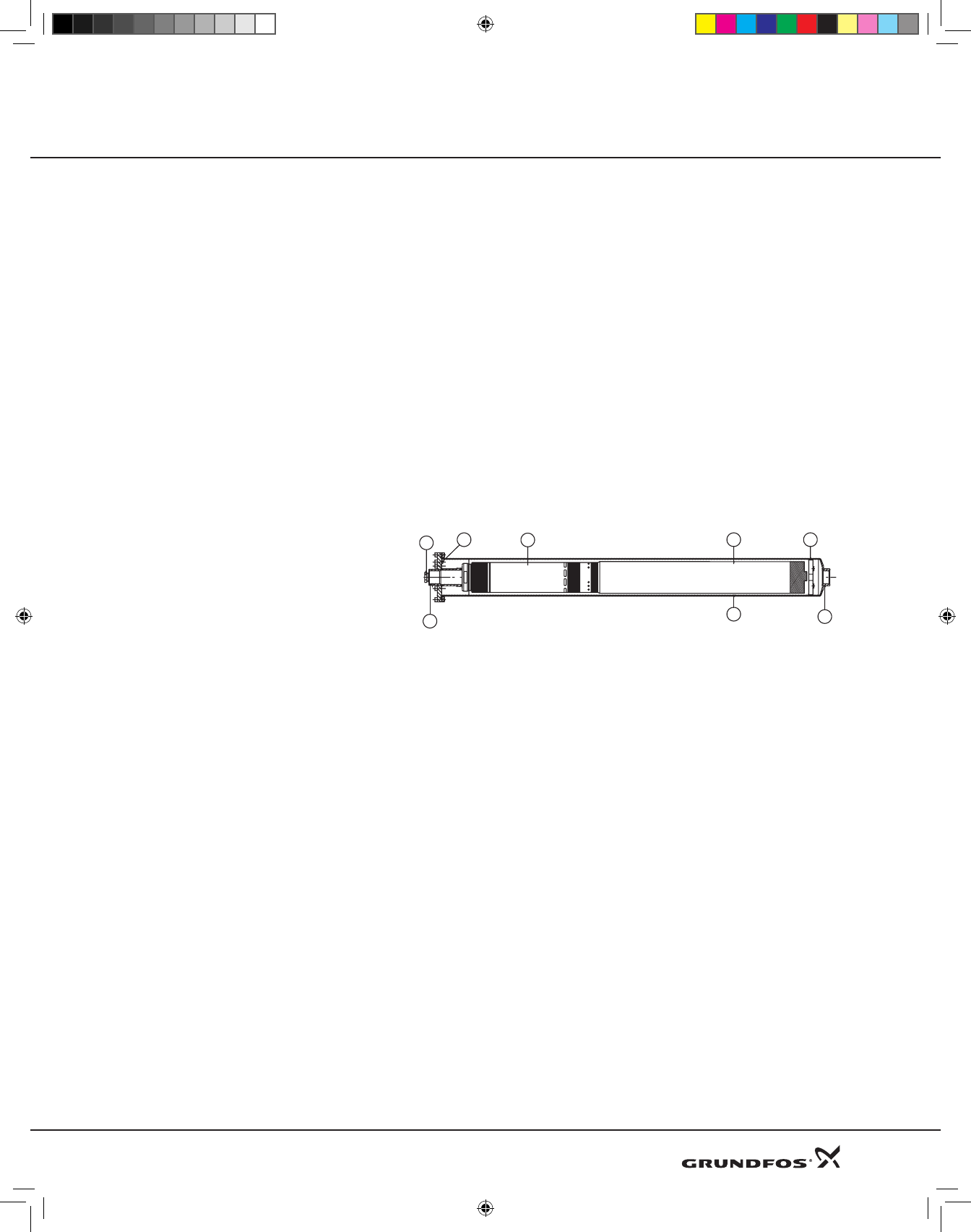
BMQE Pump Sectional Drawing
Pos.
1. Sleeve 5. SQEpump
2. Dischargeconnection 6. Cableentry
3. Suctionconnection 7. Centeringdevice
4. MSE3motor 8. Airventscrew
6
2
547
3
1
8
13
DWS Product Guide 8-09.indd 13 8/18/2009 2:32:33 PM
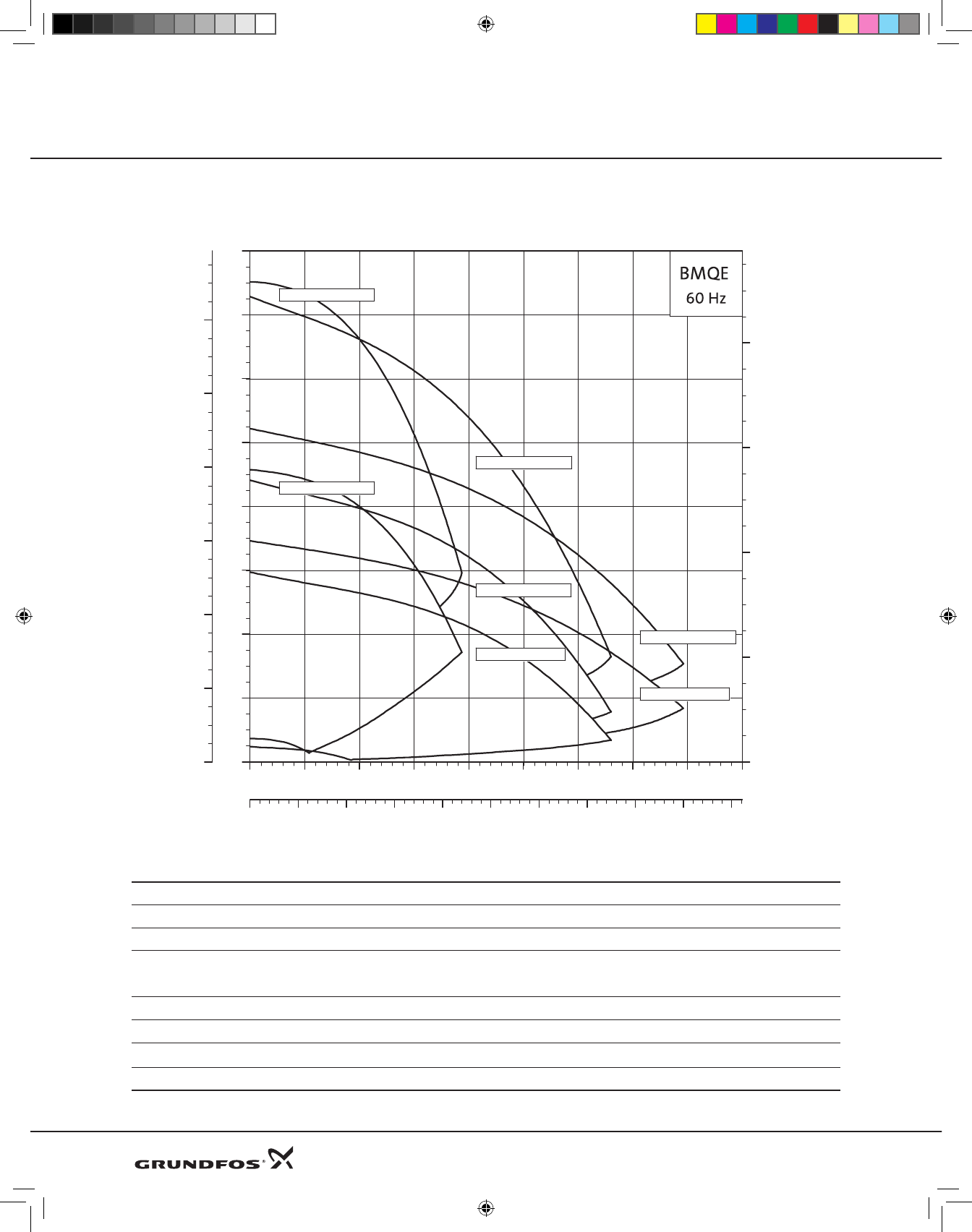
Performance range, 60 Hz
Product range
Range BMQE 15 BMQE 22 BMQE 30
Nominalflowrate[USGPM(m3/h)] 15(3.4) 22(5.0) 30(6.8)
Temperaturerange +32to+95°F(0to+35°C)
Maximuminletpressure[PSI(bar)]
Maximumworkingpressure[PSI(bar)]
217(15)
347(23)
Maximumefficiency[%] 57 62 60
Flowrange[USGPM(m3/h)] 0to19(4.3) 0to33(7.5) 0to39(8.8)
Maximumpumppressure[ft(m/PSI)] 300(91.4)/130 290(88.4)/125 208(63.4)/90
Pipeconnection 1.25”NPTinlet/1”NPTdischarge
Product Guide EZ BoostTM System
0 5 10 15 20 25 30 35 Q[US GPM]
0
40
80
120
160
200
240
280
[ft]
H
0
20
40
60
80
100
120
P
[psi]
0 1 2 3 4 5 6 7 8 9 Q[m³/h]
0
20
40
60
80
H
[m]
30 BMQE 05B-90
22 BMQE 05B-120
15 BMQE 05A-110
15 BMQE 07B-180
22 BMQE 05A-80
22 BMQE 10C-190
30 BMQE 10C-130
TK01 3101 3304
14
DWS Product Guide 8-09.indd 14 8/18/2009 2:32:33 PM
Materials BMQ
Sleeve
Pos. Description Material AISI
90 Sleeve Stainlesssteel 316
91 Flange Stainlesssteel 304
92 Cableentry Stainlesssteel/
FKM 304
93 Airventscrew Stainlesssteel 304
94 O-ring FKM
Pump
Pos. Description Material AISI
1 Valvecasing Polyamide/PVDF
1a Dischargechamber Stainlesssteel 304
1d O-ring NBRrubber
3 Valveseat NBRrubber
4a Emptychamber Polyamide/PVDF
6 Topbearing NBRrubber
7 Neckring Polyamide/PVDF
7a Lockring Stainlesssteel 310
7b Neckringretainer Polyamide/PVDF 310
9b Emptychamber Polyamide/PVDF
9c Bottomchamber Polyamide/PVDF
13 ImpellerwithTCbear-
ing Polyamide/PVDF
14 Suction
interconnector Polyamide/PVDF
14a Ring Stainlesssteel 304
16 Shaftwithcoupling Stainlesssteel 304
30 Cone Polyamide/PVDF
32 Guidevanes Polyamide/PVDF
39 Spring Stainlesssteel 316LN
55 Pumpsleeve Stainlesssteel 316
64 Primingscrew Polyamide/PVDF
70 Valveguide Polyamide/PVDF
86 Lipseal NBRrubber
87 Conecomplete Polyamide/PVDF
Motor
Pos. Description Material AISI
201 Stator Stainlesssteel 304
202 Rotor Stainlesssteel 304
202a Stopring PP
202b Filter Polyester
203 Thrustbearing Carbon
205 Radialbearing Ceramic/TC
220 Motorcablewithplug EPR
222a Fillingplug NBRrubber
224 O-ring FKM
225 Topcover PPS
232 Shaftseal NBRrubber
Type key
Example 22 BMQ E 05B 120
RatedflowinUSGPM
EZBoostpump
Electronicallycontrolledpump
viaEZBoostcontroller
MotorHP
Headinfeetatratedflow
Product Guide EZ BoostTM System
1d
7a
1
70
2
39
3
1a
55
16
30
86
87
64
18
18b
18a
6
4a
9b
32
13
9c
7
14
14a
7b
92
93
91
94
90
202a
202
202b
222a
232
203
224
205
225
201
220
233
15
DWS Product Guide 8-09.indd 15 8/18/2009 2:32:34 PM
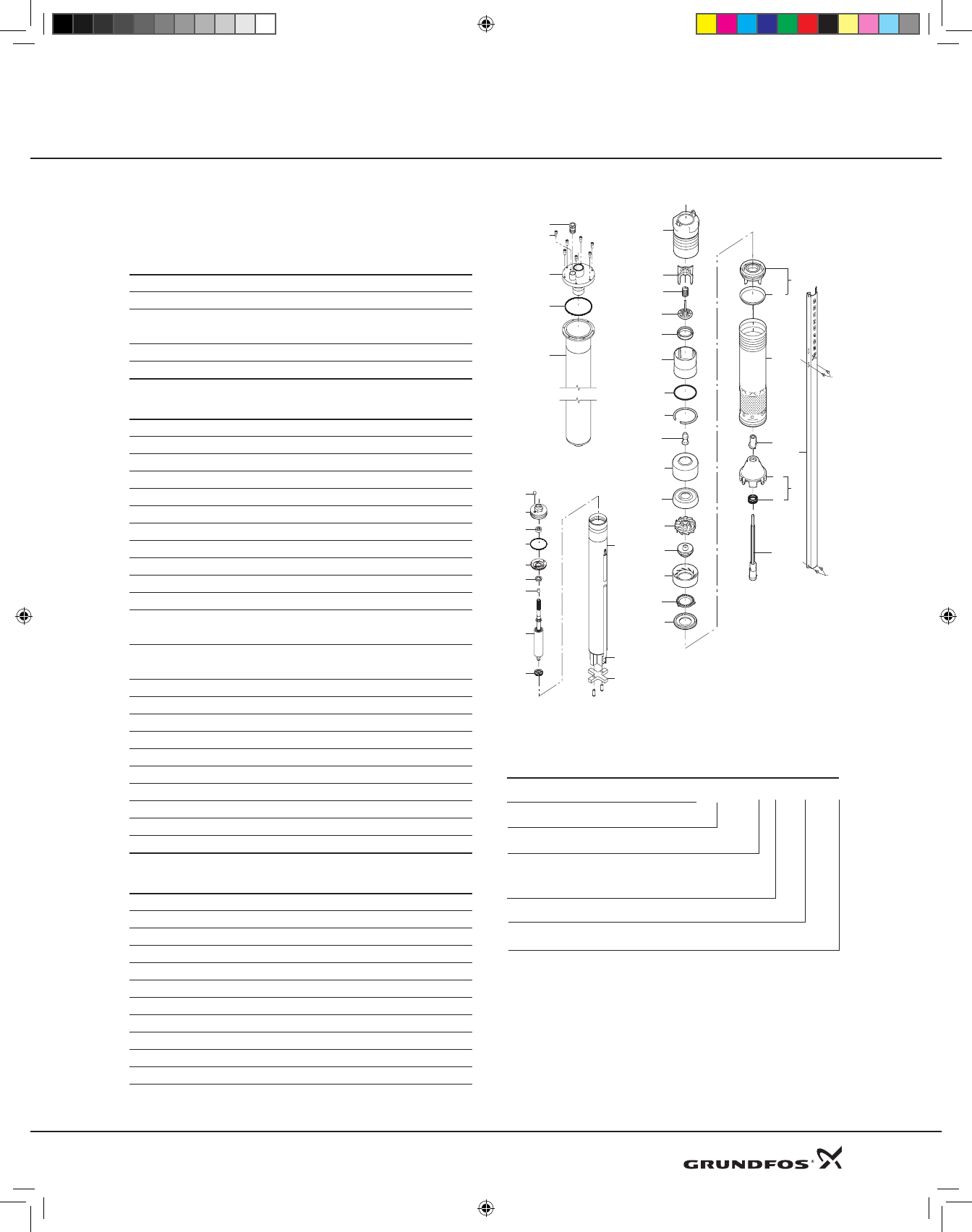
Product Guide EZ BoostTM System
0 2 4 6 8 10 12 14 16 18 Q[US GPM]
0
50
100
150
200
250
300
[ft]
H
0
20
40
60
80
100
120
140
P
[psi]
0
20
40
60
80
100
H
[m]
0.00.51.01.52.02.53.03.54.04.5Q[m³/h]
15 BMQE
60 Hz
07B-180 (5-stage)
05A-110 (3-stage)
0 2 4 6 8 10 12 14 16 18 Q[US GPM]
0.0
0.1
0.2
0.3
[hp]
P2
0
20
40
60
[%]
Eta
0.0
0.1
0.2
P2
[kW]
P2
Eta
TK01 3098 3304
16
DWS Product Guide 8-09.indd 16 8/18/2009 2:32:34 PM
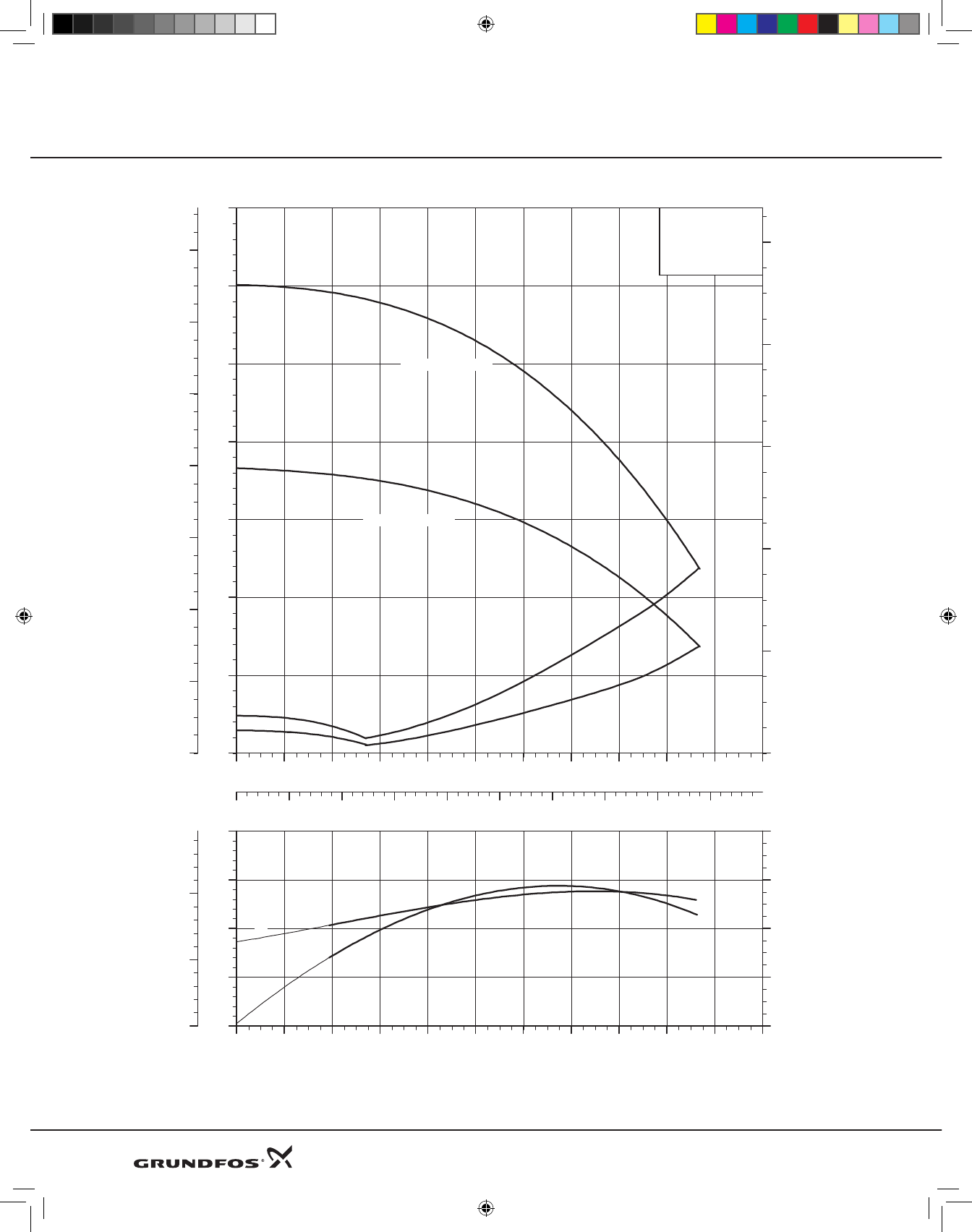
Product Guide EZ BoostTM System
0 5 10 15 20 25 30 Q[US GPM]
0
50
100
150
200
250
300
[ft]
H
0
20
40
60
80
100
120
140
P
[psi]
0
20
40
60
80
100
H
[m]
0 1 2 3 4 5 6 7 Q[m³/h]
05A-80 (2-stage)
05B-120(3stage)
10C-190(5-stage)
0 5 10 15 20 25 30 Q[US GPM]
0.0
0.2
0.4
0.6
[hp]
P2
0
20
40
60
[%]
Eta
0
0
0
P2
[kW]
P2
Eta
TK01 3099 3304
17
DWS Product Guide 8-09.indd 17 8/18/2009 2:32:34 PM
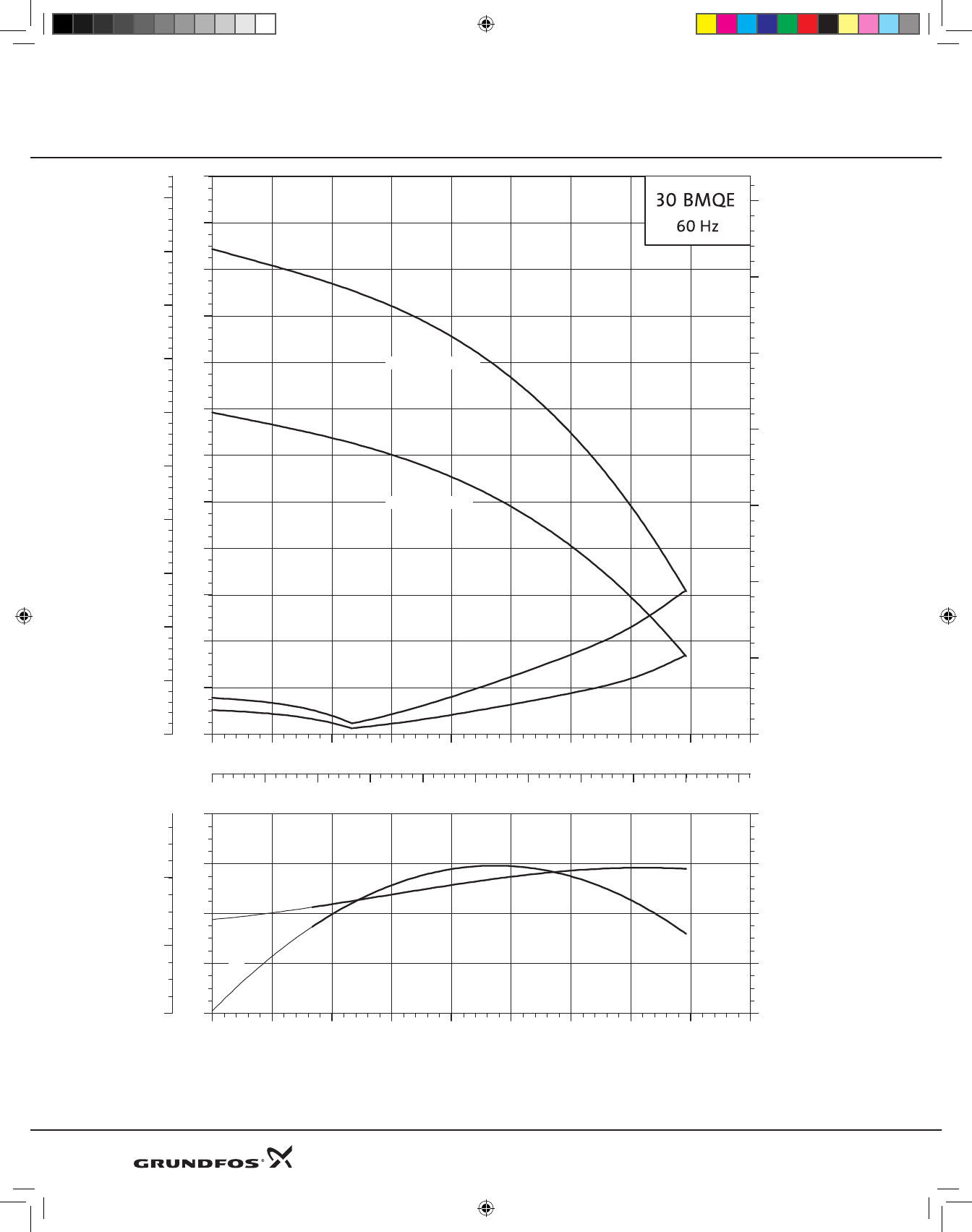
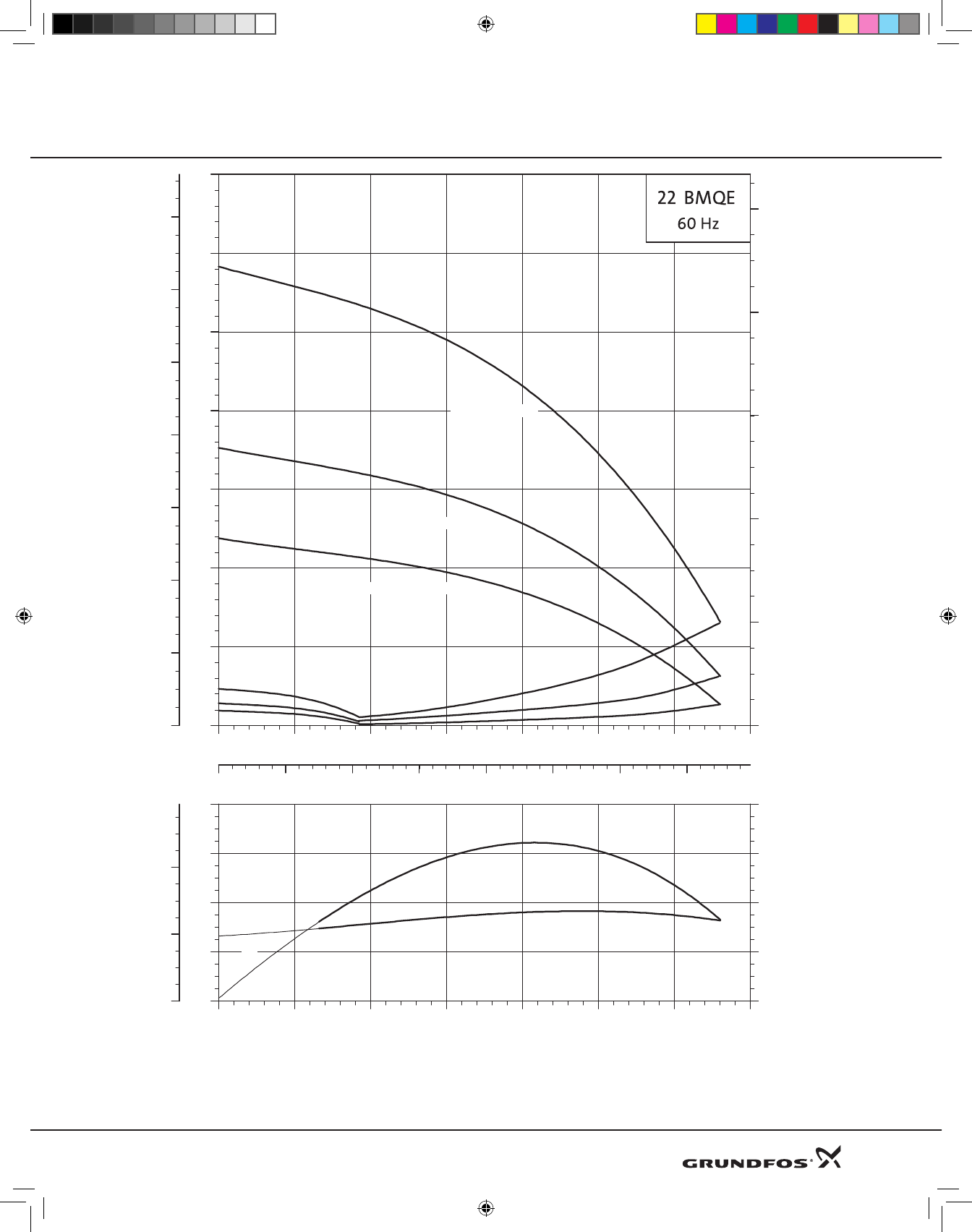
Product Guide EZ BoostTM System
0 5 10 15 20 25 30 35 Q[US GPM]
0
20
40
60
80
100
120
140
160
180
200
220
[ft]
H
0
10
20
30
40
50
60
70
80
90
P
[psi]
0 1 2 3 4 5 6 7 8 9 Q[m³/h]
0
10
20
30
40
50
60
70
H
[m]
05B-90 (2-stage)
10C-130(3-stage)
0 5 10 15 20 25 30 35 Q[US GPM]
0.0
0.2
0.4
0.6
[hp]
P2
0
20
40
60
[%]
Eta
0
0
0
P2
[kW]
P2
Eta
TK01 3100 3304
18
DWS Product Guide 8-09.indd 18 8/18/2009 2:32:34 PM
Product Guide EZ BoostTM System
Model Material
number
Max. motor output
[P2] Rated
Voltage
Rated
current
[A]
Locked rotor
current
[A]
Shipping
weight
[lb (kg)]
Shipping
volume
[ft3 (m3)]
hp kW
15BMQE05A-110 91128524 0.845 0.63 110-115 9.2 11.1 26(11.8)
0.9(0.025)
22BMQE05A-80 91128527 0.845 0.63 110-115 7.8 11.1 26(11.8)
15BMQE05A-110 91128525 0.845 0.63 200-240 4.6 5.0 26(11.8)
15BMQE07B-180 91128526 1.408 1.05 200-240 7.1 8.0 29(13.2)
22BMQE05A-80 91128528 0.845 0.63 200-240 3.9 5.0 26(11.8)
22BMQE05B-120 91128529 1.408 1.05 200-240 5.6 8.0 29(13.2)
22BMQE10C-190 91128530 2.320 1.73 200-240 9.9 11.1 31(14.1)
30BMQE05B-90 91128531 1.408 1.05 200-240 6.0 8.0 31(14.1)
30BMQE10C-130 91128533 2.320 1.73 200-240 9.5 11.1 31(14.1)
Weights and electrical data
43.3"/1100
Cable
entry
Airvent
screw
0.8"/20.5
ø4.6"/116
ø3.5"/88.9
1.25"NPT
1.0"NPT
Dimensional sketch [in/mm]
19
DWS Product Guide 8-09.indd 19 8/18/2009 2:32:35 PM
Product Guide EZ BoostTM System
Main power supply to pump 1 x 200-240 V –10%/+6%, 60 Hz
1 x 110-115 V –10%/+6%, 60 Hz
Starting Soft starting.
Stopping SoftstoppingwhenstoppedbytheEZBoostcontroller
Run-uptime Maximum:2seconds.
Nolimitationtothenumberofstarts/stopsperhour.
Motorprotection Builtintothepump.
Protectionagainst:
Dryrunning
Overvoltageandundervoltage
230Vcutsoutat<150Vand>280V
115Vcutsoutat<75Vand>150V
Overload
Overtemperature
Soundpressurelevel Thesoundpressurelevelis<74db[A]atadistanceof3feet(1meter).It is recommended by
Grundfos that the pump be installed with sound and vibration dampening equipment such as;
flexible piping adapters and anti-vibration mounting. The pump should not be mounted in or
adjacent to living quarters. The pump can also be wrapped with sound proofing insulation to
reduce noise. (See page 16, EZ Boost System Diagram.)
Resetfunction BMQEpumpscanberesetviaEZBoostcontroller.
Powerfactor PF=1.
Operationviagenerator ItisrecommendedthatthegeneratoroutputisequaltothemotorinputpowerP1[kW]plus
50%;min.P1+10%,however.
Pipeconnection 1.25”NPTinlet/1”NPTdischarge.
Strainer Holesofthestrainer:ø0.09”(2.3mm)
Marking ULListed,CE(SQEPumpwithMSE3motoronly)
Technical data - BMQE pump
20
DWS Product Guide 8-09.indd 20 8/18/2009 2:32:35 PM
Product Guide EZ BoostTM System
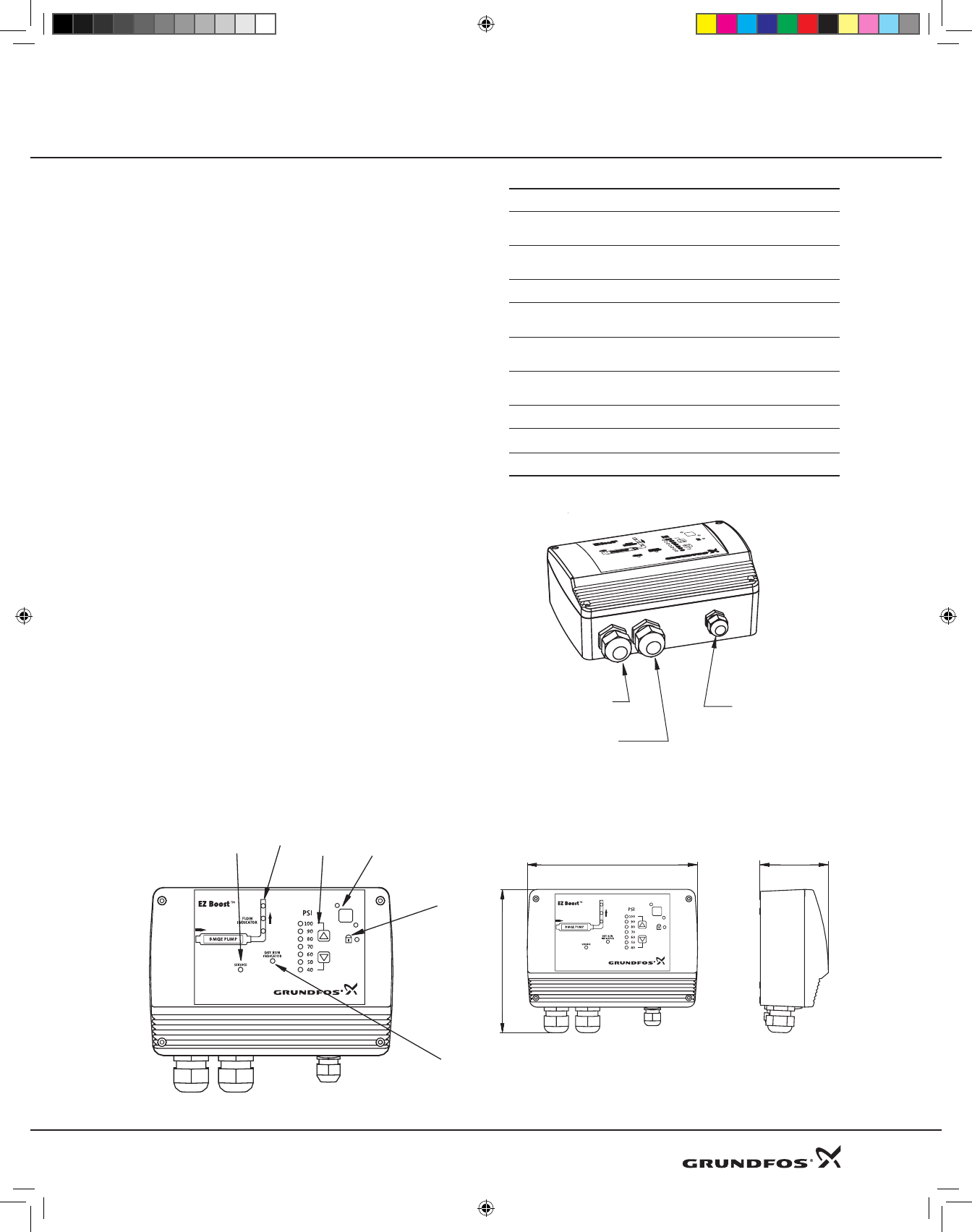
EZ Boost Controller
The EZ Boost controller is a control and communication
unitespeciallydevelopedfortheBMQEboosterpumpsin
constantpressureapplications.
TheEZBoostcontrollerprovides:
• FullcontroloftheBMQEpumps
• Two-waycommunicationwiththeBMQEpumps
• Possibilityofadjustingthepressure
• Alarmindication(LED)whenserviceisneeded
• The possibility of starting, stopping and resetting the
pumpsimplybymeansofapush-button
TheEZBoostcontrollercommunicateswiththepumpvia
powerlinecommunication,meaningthatnoextracables
arerequiredbetweentheEZBoostcontrollerandtheBMQE
pump.
TheEZBoostcontrollerfeaturesthefollowingindications
(seedrawingbelow):
1. Flowindicator
2. Systempressuresetting
3. SystemON/OFF
4. Buttonlockindicator
5. Dry-runningindicator
6. Serviceneededincaseof:
–Nocontacttopump
–Overvoltage
–Undervoltage
–Speedreduction
–Overtemperature
–Overload
–Sensordefective
TheEZBoostcontrollerincorporatesexternalsignalinput
forpressure sensor anda pump status relay foruse with
devisesdependantonpumpstatus.
Voltage 1x100-240V–10%/+6%,60Hz
Power
consumption 5W
Current
consumption Maximum130mA
Enclosureclass NEMA3R(IP55)
Ambient
temperature
Inoperation:-22to+122°F(-30to+50°C)
duringstorage:-22to+140°F(-30to+60°C)
Relative
airhumidity 95%
Pumpcable MaximumlengthbetweenEZBoostcontrol-
lerandpump:650ft(198m).
Back-upfuse Maximum:16A
Marking ULListed,CE
Load Max.100mA
23
4
1
5
6
Powersupply
entry
Submersible
dropcableentry
Pressuresensor
entry
9 3/15 in. (232 mm) 4 1/2 in. (114 mm)
7 11/16 in. (195 mm)
21
DWS Product Guide 8-09.indd 21 8/18/2009 2:32:35 PM
Product Guide EZ BoostTM System
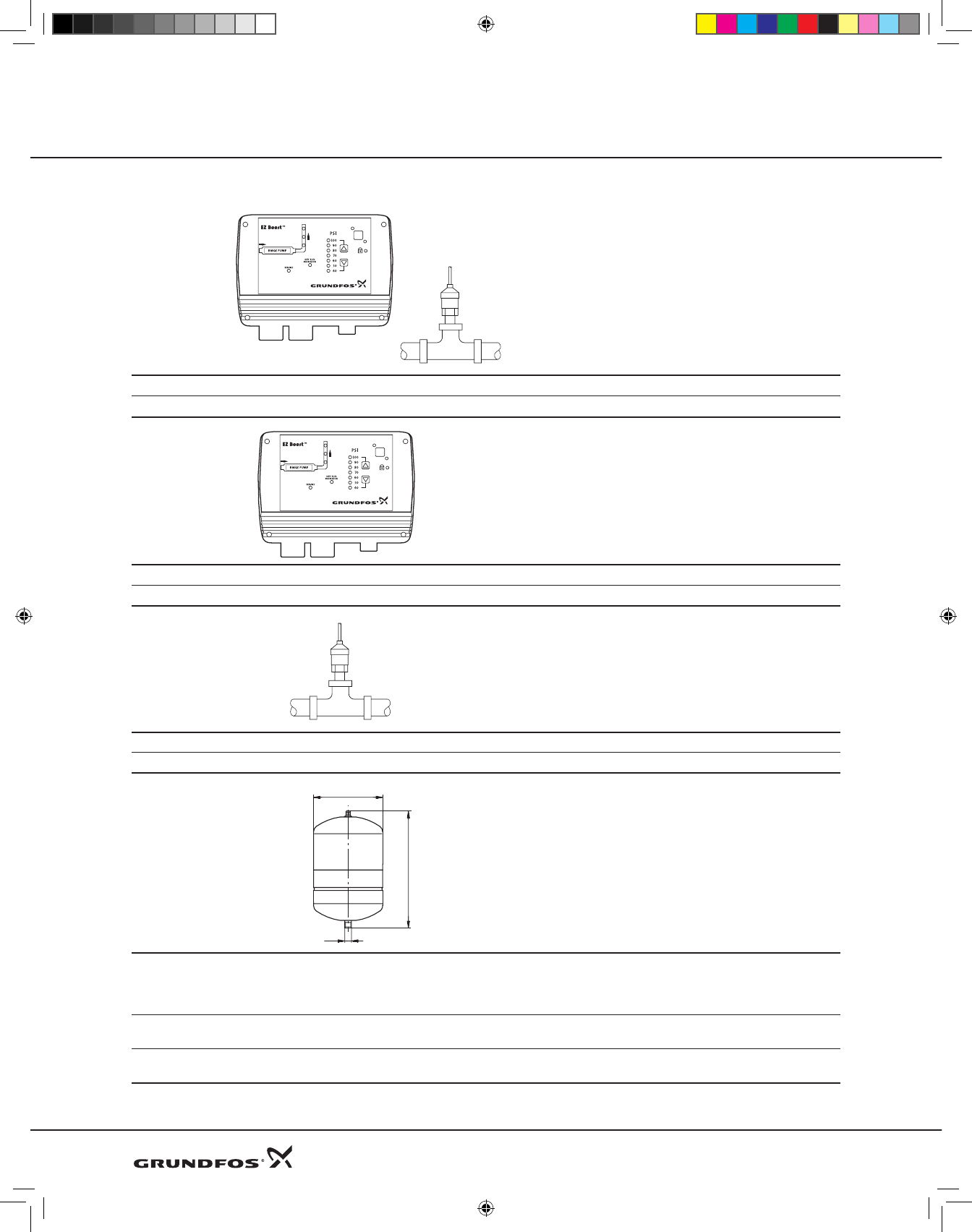
Accessories
EZ Boost constant pressure kit
Description Rating Materialnumber
EZBoostcontrollerandpressuresensor 40to100PSIsettingrange 91128636
EZ Boost controller
Description Rating Materialnumber
EZBoostcontroller 40to100PSIsettingrange 91121987
Sensor
Description Rating Materialnumber
PressuresensorkitforEZBoostcontroller 0to120PSI,1/2”NPT 96437852
Diaphragm tank
Dutyrange
Pre-chargepressure: 40PSI
Max.operatingpressure: 150PSI
Max.liquidtemperature: 200°F
Materials
Liner: Polypropylene
Connection: Lead-freebrass
Tank: Stainlesssteel,AISI304
Description G
connection
D
[in(mm)]
H
[in(mm)]
Weight
[lbs(kg)]
Material
number
Diaphragmtank,
2gallon 3/4”NPT 8(203) 12.63(321) 5(2.3) 91121984
G
D
H
22
DWS Product Guide 8-09.indd 22 8/18/2009 2:32:36 PM
Product Guide EZ BoostTM System
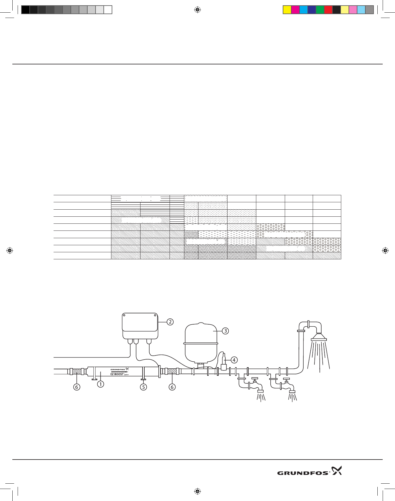
EZ Boost Quick Guide
EZ Boost Quick Selection Guide
Example:
1. Themaximumdemandis15GPM(3.4m3/h).
2. Thepressurerequiredis70PSIsystempressure
atthetapsinthebuilding.
3. Thenormalminimuminletpressure(e.g.city
pressure)is20PSI.
4. Theadditionalboostrequiredis50PSIat15GPM
(3.4m3/h).
5. Selecta15BMQE05A-110.
EZ Boost System Diagram
TheEZBoostConstantPressureSystemshouldconsistof:
Pos.
1. EZBoostBMQEpump
2. EZBoostcontroller
3. Diaphragmtank
(recommendedsize2U.S.gallons(8liter)/130psi)
Additional(boost)
pressurerequired
5 10 15 20 25 30 35 39
Flowrequiredingallonsperminute(GPM)
inPSI
90
80
70
60
50
40
30
20
10
15 BMQE 05A-11015 BMQE 05A-110
30 BMQE 05B-90
30 BMQE 05B-90
30 BMQE 10C-13030 BMQE 10C-130
22 BMQE 10C-190
22 BMQE 10C-190
22 BMQE 05B-120
22 BMQE 05B-120
22 BMQE 05A-80
22 BMQE 05A-80
15 BMQE 07B-180
15 BMQE 07B-180
4. Pressuresensor
5. Mountingbrackets
6. Flexconnector
23
DWS Product Guide 8-09.indd 23 8/18/2009 2:32:36 PM
PRE-INSTALLATION
A guide to the EZ Boost System
The EZ Boost Constant Pressure System automatically
balances water surges and equalizes flow and pressure
according to consumption. In other words, the system
maintains a constant water pressure in spite of varying
water consumption. The pressure is registered by means
of the pressure sensor and transmitted to the controller.
ThecontrolleradjuststheEZBoostBMQEpumpperform-
anceaccordingly.TheEZ Boost Constant Pressure System
features:
• Quickandeasyinstallation:ready-to-usesystem
requiringminimumspace
• Highuserconvenience:constantpressureregardlessof
waterconsumption
• Easilyadjustablepressurelevel:pushbuttoncontrol
• Continuouscontrolandmonitoringofpumpoperation
• Integrateddry-runningprotection
• Integratedoverloadprotection
• Integratedprotectionagainstovervoltageandunder
voltage
• Softstartsystem
Function
Whenatapisopened,thepressure in the tank willstart
todrop.Thesystemmaintainsaconstantpressurewithin
themaximumpumpperformanceinspiteofvaryingwater
consumption.
Thepressureisregisteredbymeansofthepressuresensor,
which transmits a signal to the controller. The controller
adjusts the pump performance accordingly to maintain
constantpressurebychangingthepumpspeed.
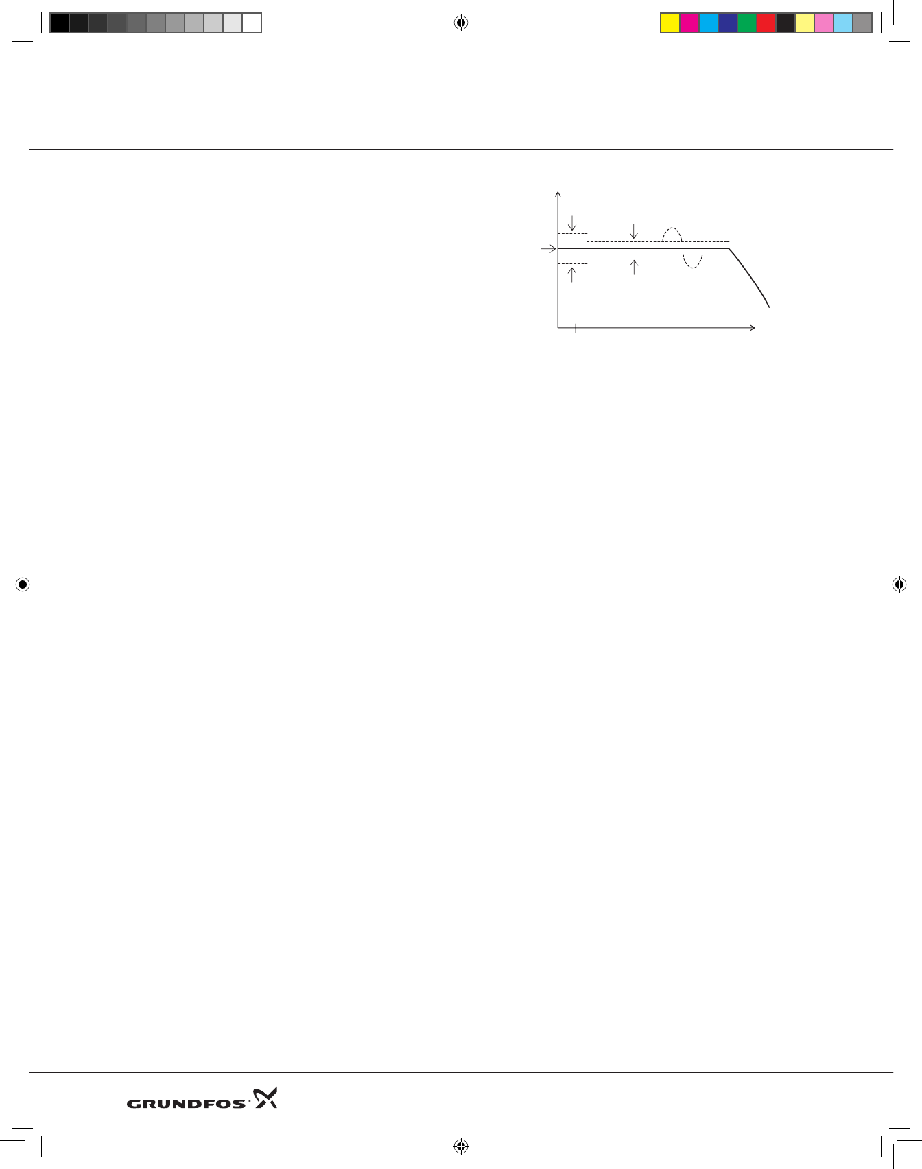
Atlowflowthepressurewilldropslowly.Whenthepres-
sureinthetankis7PSIbelowthesetpoint,thepumpwill
start. When the pressure is 7 PSI above the setpoint, the
pumpwillstop.
EventhoughtheEZBoostcontrolleriscontrollingthepres-
surewithin±3PSI,largerpressurevariationsmayoccurin
thesystem. If the consumption is suddenly changed, e.g.
if a tap is opened, the water must start flowing before
the pressure can be made constant again. Such dynamic
variations depend on the pipe work, but, typically, they
willliebetween7and14PSI.Ifthedesiredconsumptionis
higherthanthequantitythepumpisabletodeliveratthe
desiredpressure,thepressurefollowsthepumpcurveas
illustratedinthefarrightoffig.1.
Fig.1
Atlargeflowrates,thepressurewilldropquicklyandthe
pumpwill startimmediatelyandmaintainconstantpres-
sure.Whenthesystemisrunning,theEZBoostcontroller
makessmalladjustmentstothepressuretodetectwhether
thereisconsumption.Ifthereisnone,thepumpwillsimply
refillthetankandstopafterafewseconds.
Pressure
Flow
A
Stop
+7PSI
Start
-7PSI
Controlling
±3PSI
Dynamic
variations
±7PSI
GPM0.8
A=Pressuresetting
Product Guide EZ BoostTM System
24
DWS Product Guide 8-09.indd 24 8/18/2009 2:32:37 PM
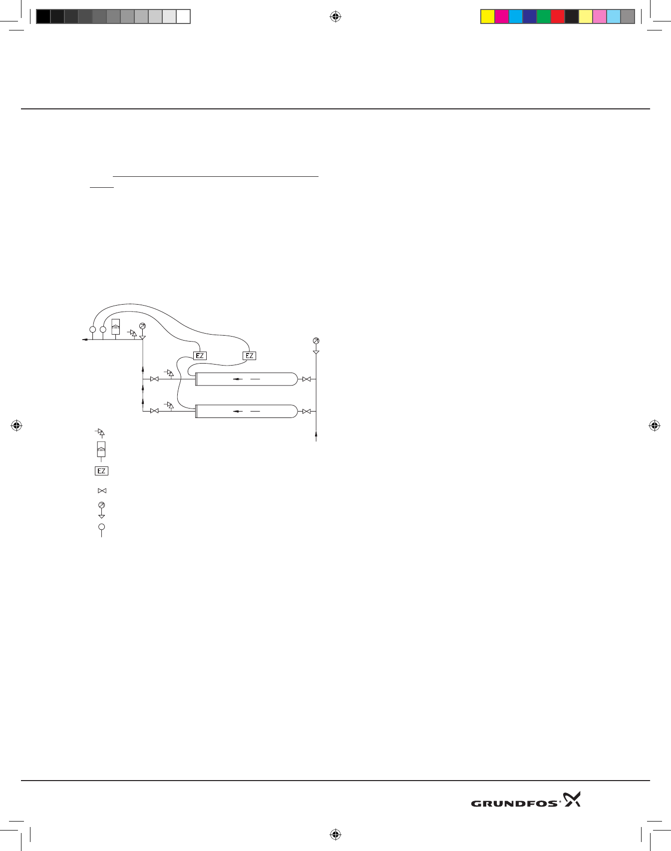
1
2
Air escape valve
Diaphragm tank
EZ Boost controller
Isolation valve
Pressure gauge
Pressure sensor
BMQE pumps connected in parallel
When connecting BMQE pumps in parallel as shown in
fig.5,a separate EZ Boost controller must be used on each
BMQE. Set the pressure on one BMQE 10 PSI lower than
theother.
For BMQE pumps connected in parallel, mounted above
each other, it is recommended to connect the pipes as
showninfig.5.ThislayoutensuresthattheBMQEpumps
arefilledwithwaterbeforestarting.
Fig.5 BoosterunitwithtwoBMQEpumps
connectedinparallel,mountedaboveeach
other.
Notes:
• AllBMQEmodulesaresuppliedwithanon-return
valve.
• BMQEmodulesconnectedinparallelmayalsobe
installedvertically.
• Asventingproblemsmayariseinsuchinstallations,itis
advisabletoinstallsuitableairventdevices.
• TheBMQEshouldbepositionedwiththedischargeand
airventatthetopwheninstalledvertically.
• WhenthemaximumflowforBMQEpumpsinparallel
will exceed 35 GPM, a 4-gallon or two 2-gallon dia-
phragmtank(s)shouldbeused.
Product Guide EZ BoostTM System
25
DWS Product Guide 8-09.indd 25 8/18/2009 2:32:37 PM

DWS Product Guide 8-09.indd 26 8/18/2009 2:32:37 PM
Product Guide MQ
MQ
Flowbasedpressureboostingsystem
60Hz
DWS Product Guide 8-09.indd 27 8/18/2009 2:32:39 PM

General data Page No.
Application 29
Typekey 29
Pumpedliquids 29
Operatingconditions 29
Technicaldata 29
Featuresandbenefits 29
Controlpanel 30
Productrange 30
Technical data
Electricaldata 30
Dimensions 30
Materialspecifications 31
Floodedsuctionperformancecurves 32
MQ3-35suctionliftperformancecurves 33
MQ3-45suctionliftperformancecurves 34
Accessories 35
28
Contents
DWS Product Guide 8-09.indd 28 8/18/2009 2:32:39 PM

29
Product Guide
Application
The MQ pump is designed for water supply and pressure
boosting ...
• homes
• cabins,cottages
• onfarmsaswellas
• gardens
The pump is suitable for pumping of potable water and rain
water.
Type Key
Example MQ 3 -35 A - B - A -BVBP
Pump range
Rated flow [m³/h]
Max. head [m]
Code for pump version
A: Standard
Code for pipework connection
B: External thread
Code for materials
A: Standard
Code for shaft seal
Pumped liquids
Potable water, rain water or other clean, thin, non-aggressive
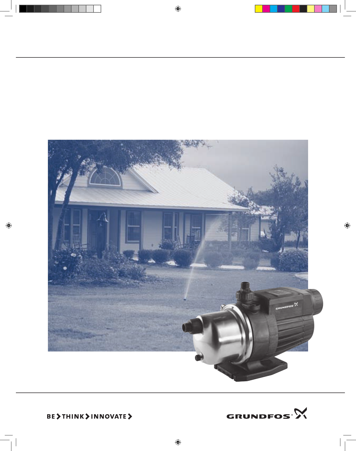
liquids not containing solid particles or fibers.
Operating conditions
System pressure: Max. 109 psi (7.5 bar).
Inlet pressure: Max. 44 psi (3 bar).
Suction lift: Max. 26 ft (8 m).
Liquid temperature: 32°F to +95°F (0°C to +35°C).
Ambient temperature: 32°F to +113°F (0°C to +45°C).
Technical data
Mains voltage:
• 115Vmodels: 1x110-120V,60Hz
• 230Vmodels: 1x220-240V,60Hz.
Voltage tolerances: –10% / +6%.
Enclosure class: IP54.
Insulation class: B.
Sound pressure level: ≤ 55 dB(A).
Agency approvals: UL, cUL
Features and benefits
• Complete system
The MQ is a complete, all-in-one unit, incorporating
pump, motor, diaphragm tank, pressure and flow sensor,
controller and check valve.
The controller ensures that the pump starts auto matically
when water is consumed and stops auto matically when
the consumption ceases. In addition, the controller
protects the pump in case of faults.
• Installation
Due to its compact design, the pump does not take up
much space and is easy to install. No space around the
pump is required.
• Simple operation
The pump features a user-friendly control panel with
ON/OFF button and indicator lights for indication of the
operational state of the pump.
• Self-priming pump
As it is self-priming, the MQ is able to pump water from a
level below the pump. Provided it is filled with water, the
pump is able to lift water from a depth of 26 ft (8 m) in
less than 5 minutes. This facilitates installa tion and start-
up of the pump and provides more re liable water supply
in installations where there is a risk of dry running and
leakages in suction hose or pipes.
• Built-in protective functions
If exposed to dry running, excessive temperature, or any
overload condition the pump will stop automatically, thus
preventing a motor burnout.
• Automatic reset
The pump features an automatic reset function. In case
of dry running or similar alarm, the pump will stop.
Restarting will be attempted every 30 minutes for a period
of 24 hours. The reset function can be de activated.
• Low noise level
Thanks to its hydraulic design and internal cooling, the
pump is very quiet, which makes it suitable for many
applications.
• Pressure tank
The built-in pressure tank reduces the number of starts
and stops in case of leakages in the pipe sys tem, causing
less wear on the pump.
• Maintenance
No maintenance of the pump is required.
MQ
Flow Based Pressure Boosting System
DWS Product Guide 8-09.indd 29 8/18/2009 2:32:39 PM
30
Product Guide
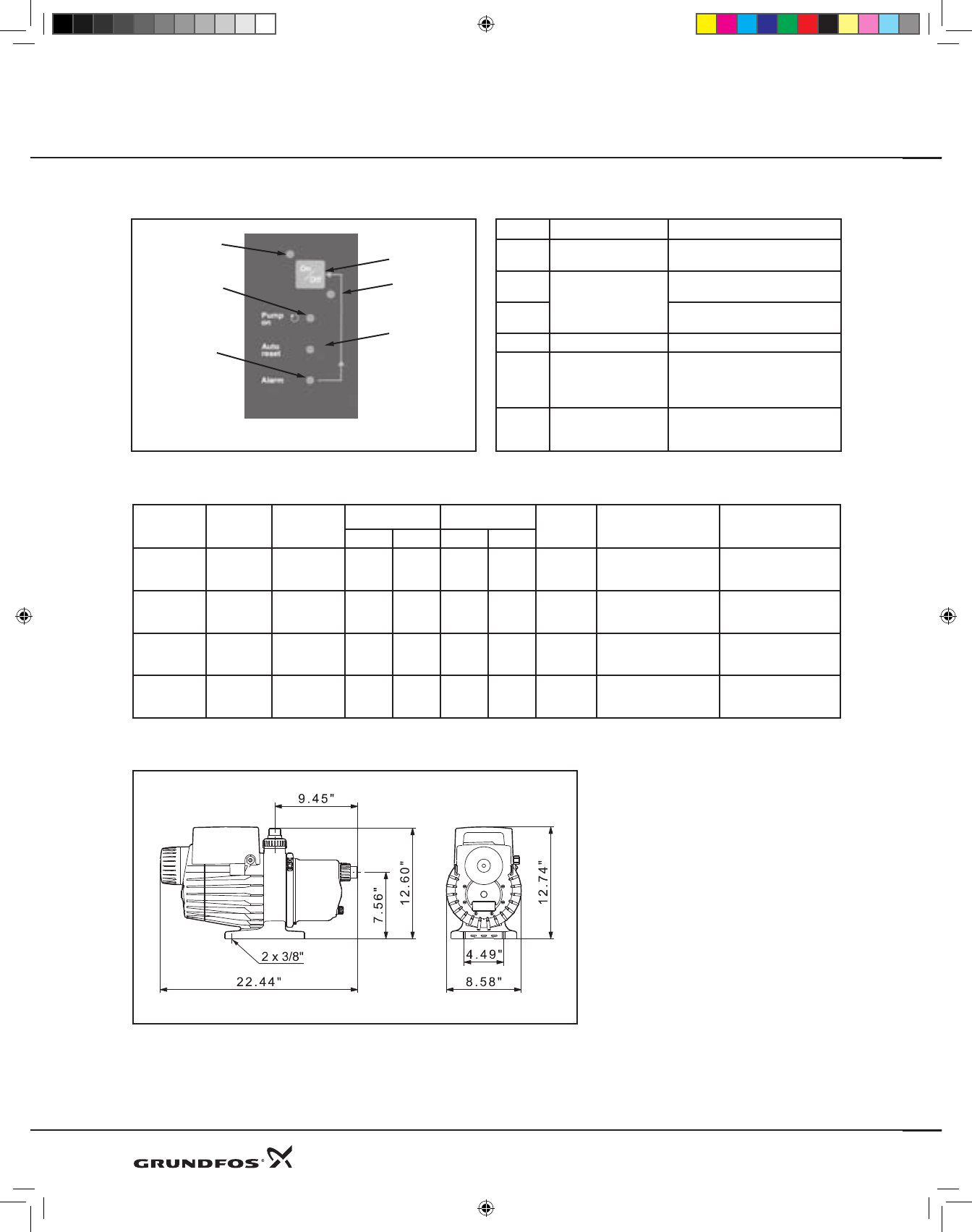
Control panel operation
1
3
5
6
4
2
TM01 9684 2600
Pos. Function Description
1 ON/OFF button The Pump is started and stopped by
means of the ON/OFF button.
2
Power indicator lights
Indicates that the pump is ready for
operation (green).
3Indicates that the pump is on
standby (red).
4 Pump ON (green) Indicates that the pump is running.
5 Auto reset (green)
Indicates that the auto reset
function is active. After an alarm,
restarting will be attempted every
30 minutes for a period of 24 hours.
6 Alarm (red)
Indicates that the pump is in alarm
state. Manual resetting is possible
by pressing the ON/OFF button.
MQ
Flow Based Pressure Boosting System
Part
Number Model PH & V AMPS P2 Weight
Net
Pounds
Cord
Connection Plug
Run Start W HP
96860172 MQ 3-35 1X110-120V 8 29 585 0.75 30.1 7.54’ - 2300mm SJTW-A
18 awg
UL Approved NEMA
5-15P - V125
96860195 MQ 3-45 1X110-120V 10 29 725 1 30.2 7.54’ - 2300mm SJTW-A
18 awg
UL Approved NEMA
5-15P - V125
96860201 MQ 3-35 1X220-240V 4 15 565 0.75 30.1 7.54’ - 2300mm SJTW-A
18 awg
UL Approved NEMA
6-15P - V250
96860207 MQ 3-45 1X220-240V 4.8 15 716 1 30.2 7.54’ - 2300mm SJTW-A
18 awg
UL Approved NEMA
6-15P - V250
Product range and electrical data
Dimensions
TM011 9799
DWS Product Guide 8-09.indd 30 8/18/2009 2:32:40 PM
31
Product Guide MQ
Flow Based Pressure Boosting System
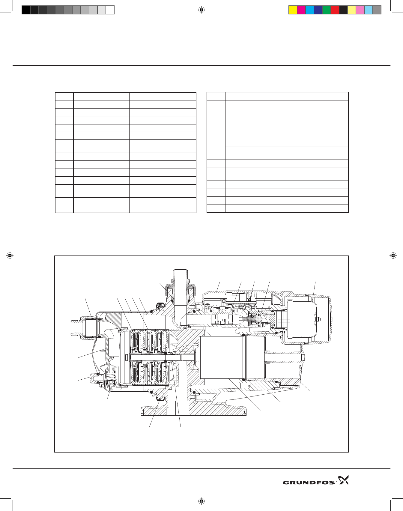
Material specification
Pos. Components Material
2 Support flange PP+30% Glass Fiber HB (f1)
4 Chamber PPO+20% Glass Fiber
7 Drain and priming plug PPO+20% Glass Fiber
10 Self-priming valve PP+30% Glass Fiber
14 Self-priming part PPO+20% Glass Fiber
16 Pump sleeve Stainless steel,
DIN W.-Nr. 1.4301, AISI 304
42 Tank cover PP+30% Glass Fiber HB (f1)
49 Impeller PPO +20% Glass Fiber-PTFE
51 Motor cover PP+30% Glass Fiber HB (f1)
65 Non-return valve POM+25% Glass Fiber
92 Clamp Stainless steel,
DIN W.-Nr 1.4301, AISI 304
100a Discharge port PPO+20% Glass Fiber
POM: Polyoximetylen
NR-rubber: Natural Rubber
PPO: Polyphenylene Oxides
PP: Polypropylene
NBR-rubber: Nitrile-Butadiene Rubber
Part
Number Model PH & V AMPS P2 Weight
Net
Pounds
Cord
Connection Plug
Run Start W HP
96860172 MQ 3-35 1X110-120V 8 29 585 0.75 30.1 7.54’ - 2300mm SJTW-A
18 awg
UL Approved NEMA
5-15P - V125
96860195 MQ 3-45 1X110-120V 10 29 725 1 30.2 7.54’ - 2300mm SJTW-A
18 awg
UL Approved NEMA
5-15P - V125
96860201 MQ 3-35 1X220-240V 4 15 565 0.75 30.1 7.54’ - 2300mm SJTW-A
18 awg
UL Approved NEMA
6-15P - V250
96860207 MQ 3-45 1X220-240V 4.8 15 716 1 30.2 7.54’ - 2300mm SJTW-A
18 awg
UL Approved NEMA
6-15P - V250
Pos. Components Material
101 Suction port PPO+20% Glass Fiber
103
104
Shaft seal:
Stationary and
rotating part
Carbon/ceramics/NBR rubber
149 Insulation disc PA 5VA (Polyammide)
150
Shaft Stainless steel,
DIN W.-Nr 1.4005, AISI 416
Motor sleeve Stainless steel,
DIN W.-Nr 1.4301, AISI 304
164 Terminal box cover PP+30% Glass Fiber 5VA (f1)
174a Pressure switch POM+25% Glass Fiber / SIL Rubber
(Silicone Rubber)
Pressure switch membrane SIL Rubber - Silicone Rubber.
180 Motor body PP+30% Glass Fiber 5VA (f1)
184 Flow sensor POM+25% Glass Fiber
O-rings NBR-rubber
101 49 16 42
100a
14
7
92
150
51
184164 174a 42
103
104
65
10 180
DWS Product Guide 8-09.indd 31 8/18/2009 2:32:42 PM
32
Product Guide MQ
Flow Based Pressure Boosting System
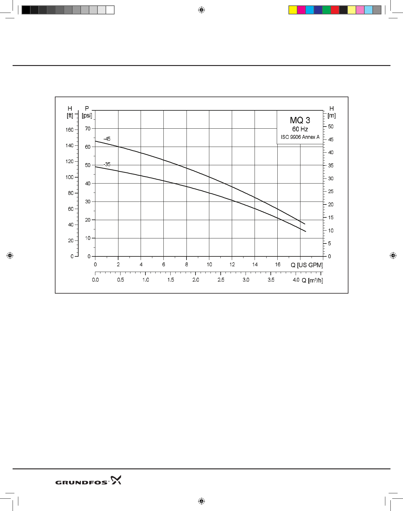
Flooded suction (0 PSI inlet) performance curves*
*See suction lift performance curves for installations with water level below intake.
DWS Product Guide 8-09.indd 32 8/26/2009 10:58:47 AM
33
Product Guide MQ
Flow Based Pressure Boosting System
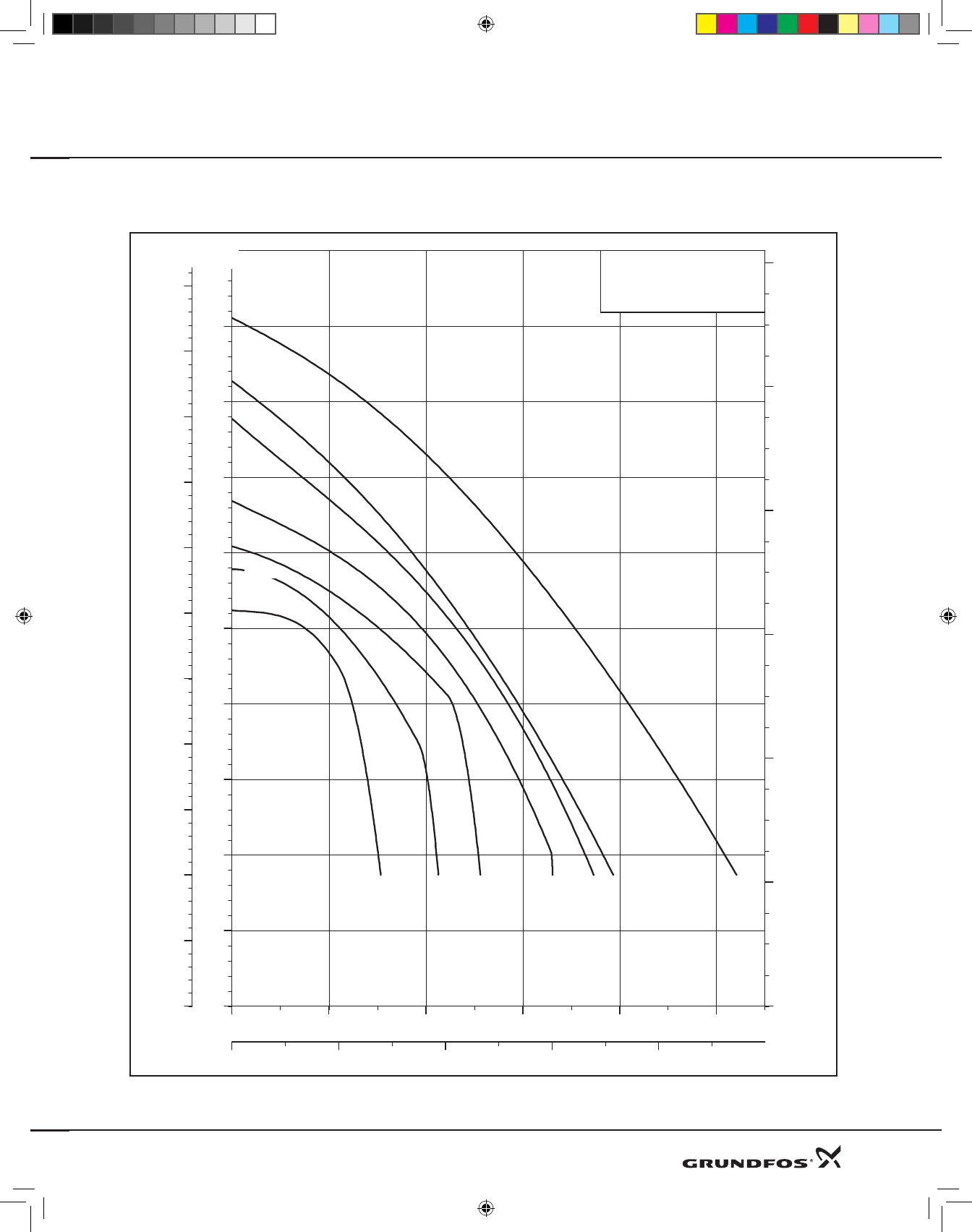
MQ 3-35 Suction lift performance curves
0 4 8 12 16 20 Q [US GP M]
0
5
10
15
20
25
30
35
40
45
p [psi]
0 1 2 3 4 Q [m³/h]
0
10
20
30
40
50
60
70
80
90
100
110
H [ft]
0
8
16
24
32
40
[m]
H
MQ 3-35 model B
60 Hz
26.2 Ft
23.0 Ft
19.7 Ft
13.1 Ft
6.6 Ft
3.3 Ft
0 Ft
Provided it is filled with water, the pump is able to lift water from a depth of 26 ft (8 m) in less than 5 minutes.
MQ 3-35
60 Hz
DWS Product Guide 8-09.indd 33 8/18/2009 2:32:43 PM
34
Product Guide MQ
Flow Based Pressure Boosting System
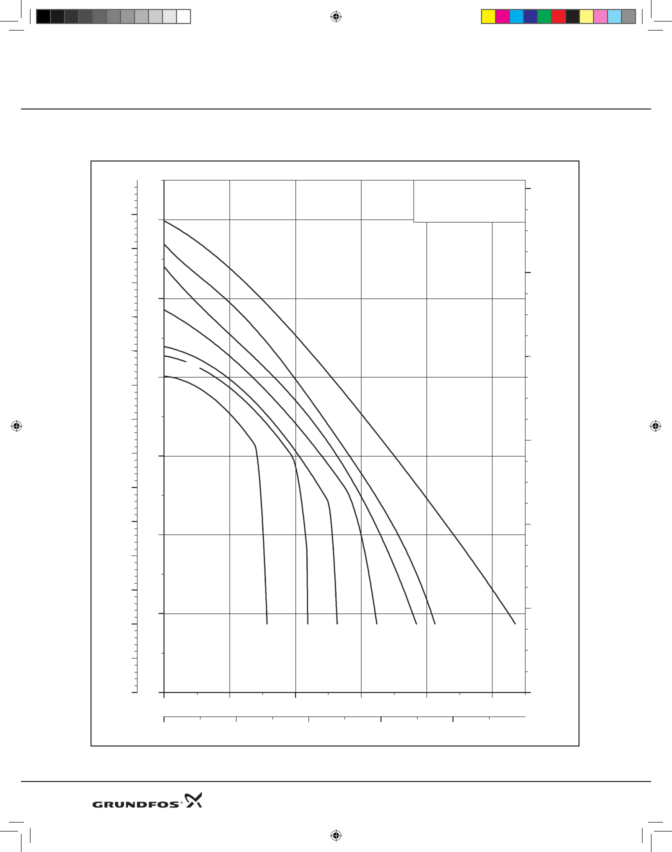
MQ 3-45 Suction lift performance curves
0 4 8 12 16 20 Q [US GP M]
0
10
20
30
40
50
60
p
[psi]
0 1 2 3 4 Q [m³/h]
0
10
20
30
40
50
60
70
80
90
100
110
120
130
140
H
[ft]
0
8
16
24
32
40
[m]
H
MQ 3-45 model B
60 Hz
26.2 Ft
23.0 Ft
19.7 Ft
13.1 Ft
6.6 Ft
3.3 Ft
0 Ft
Provided it is filled with water, the pump is able to lift water from a depth of 26 ft (8 m) in less than 5 minutes.
MQ 3-45
60 Hz
DWS Product Guide 8-09.indd 34 8/18/2009 2:32:43 PM
35
Product Guide MQ
Flow Based Pressure Boosting System
Accessories
Protection Cover:
Designed to protect the MQ Key Pad and electronics in outdoor applications.
Protection cover is required for outdoor applications where the MQ is exposed to the elements.
The protection cover is sold as an accessory PN 96693071.
The cover is made of polypropylene and is a snap fit to the MQ. Two Velcro tabs are included with the accessory to help
adhear the back end of the cover to the pump.
DWS Product Guide 8-09.indd 35 8/18/2009 2:32:44 PM

36
Basic Line Jets
DWS Product Guide 8-09.indd 36 8/18/2009 2:32:44 PM
37
JPF,JPS,JDF
ShallowWell,DeepWelland
ConvertibleJetPumps
60Hz
Product Guide Basic Line Jets
DWS Product Guide 8-09.indd 37 8/18/2009 2:32:45 PM

General data Page No.
Performancerange 39
Productrange 40
Applications 41
Pumps 41
Motors 41
Pumpedliquid 41
Agencyapprovals 41
Mountingposition 41
Electricaldata 42
Materialsofconstruction 43
Technical data
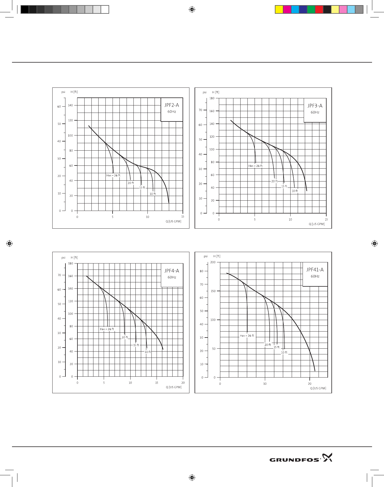
JPF 2A, 3A, 4A, 41A Shallow Well Cast Iron 46
DimensionsandWeights 46
PerformanceChart 46
PerformanceCurves 47
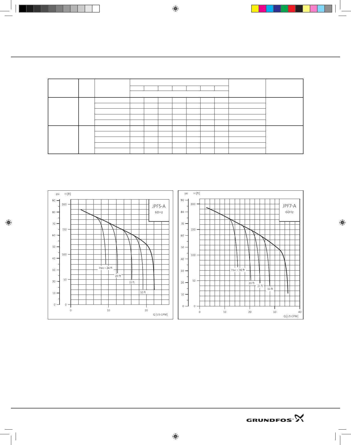
JPF 5A, 7A Convertible Cast Iron 48
DimensionsandWeights 48
ConversionInstructions 48
PerformanceChart 49
PerformanceCurves 49
DeepWellPerformanceChart 50
JPS 2A, 4A Shallow Well Stainless Steel 51
DimensionsandWeights 51
PerformanceChart 51
PerformanceCurves 52
JDF 2A, 4A Deep Well Cast Iron 53
DimensionsandWeights 53
EjectorDimensions 53
PerformanceChart 54
JPF3A Pump Tank Package Cast Iron 55
DimensionsandWeights 55
PerformanceChart 55
JPS2A Pump Tank Package Stainless Steel 56
DimensionsandWeights 56
PerformanceChart 56
38
Contents Basic Line Jets Basic Line Jets
DWS Product Guide 8-09.indd 38 8/18/2009 2:32:45 PM
39
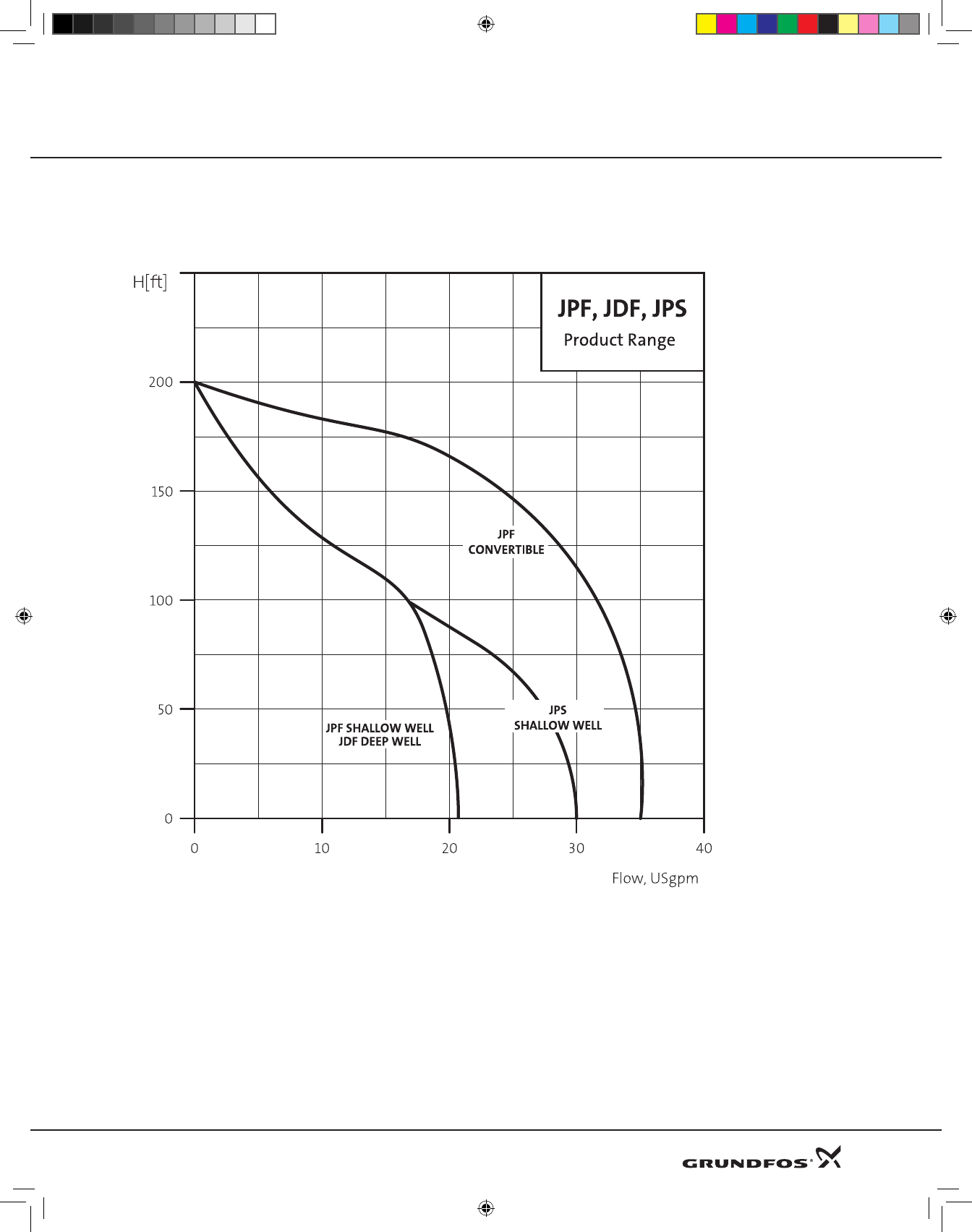
Performance range
* Capacities given are for near-sea level installations.
Product Guide Basic Line Jets
DWS Product Guide 8-09.indd 39 8/18/2009 2:32:46 PM
40
Product Guide
Product range
Model JPF 2-A JPF 3-A JPF 4-A JPF 41-A JPF 5-A JPF 7-A JPS 2-A JPS 4-A JDF 2-A JDF 4
Flow range (U.S. gpm) 1.7-13 1.7-12.2 1.7-16 1.8-21 2.6-22 2.6-35 1.7-17 3.5-28.2 1.8-10.3 0.75-13.1
Max. pump head H(ft) 135 170 172 185 200 200 140 155 145 167
Max. working pressure (psi) 87 87 87 87 110 110 110 110 87 87
Motor power (hp), Nominal 1/3 1/2 3/4 1 1.5 2 1/2 1 1/2 3/4
Maximum Fluid Temperature range 14°F to 104°F (-10 to 40°C)*
Maximum lift, Ft (Sea level) 26 26 26 26 140 140 26 26 70 80
Maximum Ambient Temp 34°F to 104°F (1 to 40°C)
Factory Pressure -Switch setting (PSI) 20-40 30-50 30-50 40-60 50-70 50-80 30-50 30-50 30-50 30-50
Storage Temp 14°F to 104°F (-10 to 40°C)
Relative Humidity 95%
Maximum Starts per hour 20
*Minimum fluid temperature on water, 32°F (0°C)
Basic Line Jets Basic Line Jets
DWS Product Guide 8-09.indd 40 8/18/2009 2:32:46 PM
41
Product Guide
Applications
Shallowwell,DeepwellandConvertiblepumpappli-
cations.Grundfosjetpumpsareself-primingcentrifu-
galpumpssuitablefordomesticwatersupplysystems,
lightagriculturalandindustrialwatertransferapplica-
tions
Pumps
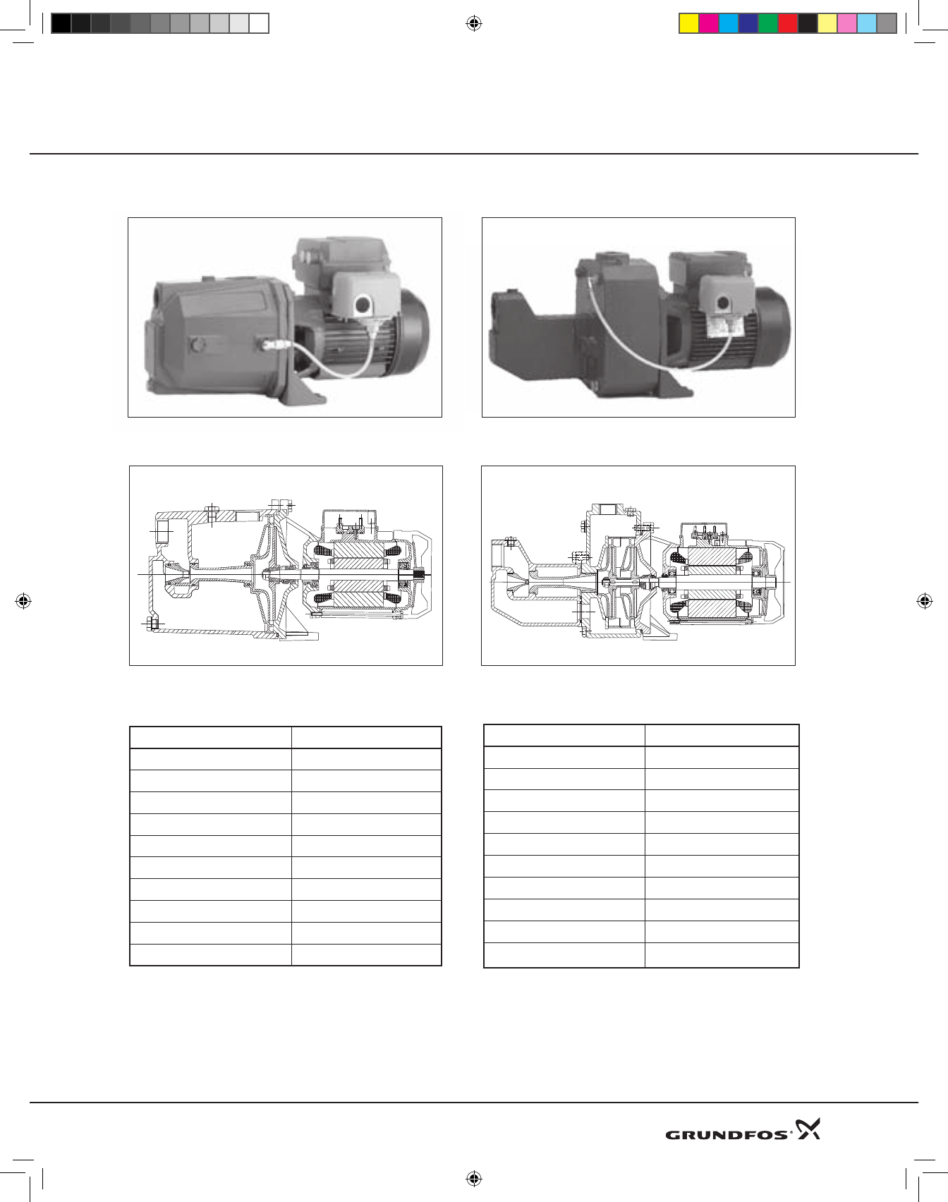
JPF2A, JPF3A, JPF4A, JPF41A Pumps:
Ruggedcastironconstruction.Single-stageshallow
wellself-primingcentrifugalpumps.Endsuction,top
dischargearrangementandTechnopolymerimpeller.
Pumphasbuilt-inejectorcompletewithcleanoutport
toclearblockagesfromnozzle.Convenientpriming
plugforeaseofprimingandairelimination.Ceramic-
Carbonbellowsmechanicalsealensurestrouble-free
operation.
JPF5A & JPF7A Pumps:
Ruggedcastironconstruction.Multistageconvertible
self-primingcentrifugalpumps.Endsuction,topdis-
chargearrangementwithdetachableejectorassembly
fordeepwellapplicationsandTechnopolymerimpel-
lers.Convenientprimingplugforeaseofprimingand
airelimination.Ceramic-Carbonbellowsmechanical
sealensurestrouble-freeoperation.
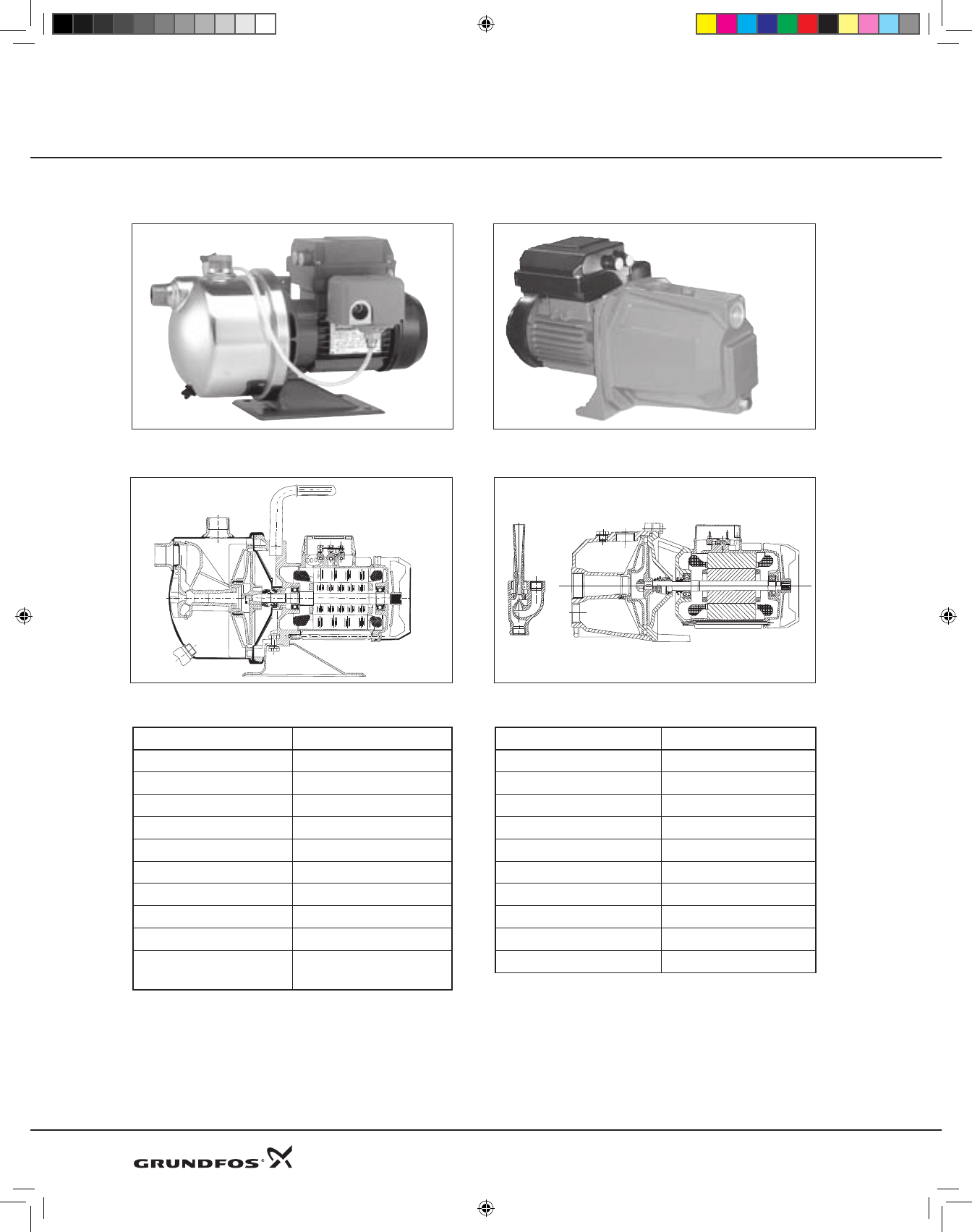
JDF2A & JDF4A Pumps:
Ruggedcastironconstruction.Single-stagedeep
wellself-primingcentrifugalpumps.Endsuction,top
dischargearrangementandTechnopolymerimpel-
ler.Pumphasseparatedeepwellportforconnection
toDeepWellejectorkit.Convenientprimingplugfor
easeofprimingandairelimination.Ceramic-Carbon
bellowsmechanicalsealensurestrouble-freeopera-
tion.
JPS2A & JPS4A Pumps:
Corrosionresistantstainlesssteelconstruction.
Singlestageshallowwellself-primingcentrifugal
pumps.Endsuction,topdischargearrangementand
Technopolymerimpeller.Ceramic-Carbonbellows
mechanicalsealensurestrouble-freeoperation.
Motors
All jet pump motors are totally enclosed and fan-
cooled design for quiet operation and superior protec-
tion in harsh environments. Stainless steel motor shaft
offers excellent corrosion resistance. Double, oversized
greased ball bearings are maintenance-free sealed for
life. All motors have built-in thermal overload protec-
tion and are capacitor-run, with no switches to fail.
Drive end motor bearing protected by durable lip seal.
InsulationclassF,motorprotectionIP44,terminalbox
protectionIP55.
Pumped Liquid
Onlyuseonclean,non-viscous,non-aggressive,non-
explosiveliquids.Pumpnottobeusedonpoolwater
applicationsorhydrocarbontransfer(i.e.diesel,gaso-
line,etc).
Agency Approvals:
CSA-StdC22.2No108,No77-95.
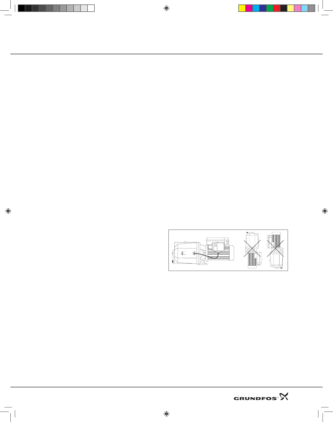
Mounting Position:
Shaftinhorizontalpositiononlyforallpumps.
Basic Line Jets
DWS Product Guide 8-09.indd 41 8/18/2009 2:32:46 PM
42
Product Guide
Electrical Data:
Model
Electrical Data
Voltage
60 Hz
kW
Maximum
hp
Nominal S.F.
I
Amps Capacitor
µF
JPF2A 115 0.65 1/3 1.75 6 40
JPF2A 230 0.65 1/3 1.75 3 10
JPF3A 115 0.85 1/2 1.6 7.5 20
JPF3A 230 0.85 1/2 1.6 3.8 12.5
JPF4A 115 1.10 3/4 1.5 10 64
JPF4A 230 1.10 3/4 1.5 5 16
JPF41A 115 1.31 1 1.4 12 80
JPF41A 230 1.31 1 1.4 6 20
JPF5A 230 1.70 1.5 1.3 8 31.5
JPF7A 230 2.40 2 1.2 11 40
JPS2A 115 0.88 1/2 1.6 7.6 50
JPS2A 230 0.82 1/2 1.6 3.7 12.5
JPS4A 115 1.6 1 1.4 13.6 80
JPS4A 230 1.53 1 1.4 7 20
JDF2A 115 0.75 1/2 1.6 7 50
JDF2A 230 0.75 1/2 1.6 3.4 12.5
JDF4A 115 0.88 3/4 1.5 8 64
JDF4A 230 0.88 3/4 1.5 4 16
Basic Line Jets Basic Line Jets
DWS Product Guide 8-09.indd 42 8/18/2009 2:32:46 PM
43
Product Guide
JPF 2A, 3A, 4A, 41A* Shallow Well
Materials: JPF 2A, 3A, 4A, 41A
Shallow Well
Descriptions Material
Motor Stool Cast Iron
Shaft Seal Carbon/Ceramic/NBR
O-Rings & Gaskets NBR
Base Plate Cast Iron
Pump Housing Cast Iron
Impeller Noryl©
Motor Shaft Stainless Steel AISI 416
Tubing Polyethylene
Diffuser Noryl©
Venturi Tube and Nozzle Noryl©
Note:Noryl©isaregisteredtrademarkofGeneralElectricCompany
JPF 5A, 7A Convertible*
Materials: JPF 5A, 7A
Convertible
Descriptions Material
Motor Stool Cast Iron
Shaft Seal Carbon/Ceramic/NBR
Motor Shaft Stainless Steel AISI 303
O-Rings & Gaskets NBR
Base Plate Cast Iron
Pump housing Cast Iron
Impellers Noryl©
Tubing Polyethylene
Diffuser Noryl©
Venturi Tube and Nozzle Noryl©
Note:Noryl©isaregisteredtrademarkofGeneralElectricCompany
*Available in Canada*41A available in Canada
Basic Line Jets
DWS Product Guide 8-09.indd 43 8/18/2009 2:32:47 PM
44
Product Guide
JPS 2A, 4A Shallow Well
Materials: JPS 2A, 4A Shallow Well
Descriptions Material
Motor Stool Cast Iron
Shaft Seal Carbon/Ceramic/NBR
O-Rings & Gaskets NBR
Base Plate Steel
Pump housing Stainless Steel AISI 304
Impeller Noryl©
Motor Shaft Stainless Steel AISI 303
Tubing Polyethylene
Seal cover Stainless Steel AISI 304
Nozzle-Venturi Diffuser
Assembly
Noryl©
Note:Noryl©isaregisteredtrademarkofGeneralElectricCompany
JDF 2A, 4A Deep Well
Materials: JDF 2A, 4A Deep Well
Descriptions Material
Motor Stool Cast Iron
Shaft Seal Ceramic/Ceramic/NBR
O-Rings & Gaskets NBR
Base Plate Cast Iron
Pump housing Cast Iron
Impeller Noryl©
Tubing Polyethylene
Motor Shaft Stainless Steel AISI 303
Diffuser Noryl©
Venturi Tube Noryl©
Note:Noryl©isaregisteredtrademarkofGeneralElectricCompany
Basic Line Jets Basic Line Jets
DWS Product Guide 8-09.indd 44 8/18/2009 2:32:49 PM
45
Product Guide
JPF3A Pump package*
Cast Iron
*Available in Canada
Materials: JPF3A Pump Package
Descriptions Material
Motor Stool Cast Iron
Shaft Seal Carbon/Ceramic/NBR
O-Rings and Gaskets NBR
Base Plate Cast Iron
Pump Housing Cast Iron
Impeller Noryl©
Motor Shaft Stainless Steel AISI 416
Tubing Polyethylene
Diffuser Noryl©
Venturi Tube and Nozzle Noryl©
Tank Stainless Steel AISI304
Bladder Butyl
Note:Noryl©isaregisteredtrademarkofGeneralElectricCompany
JPS2A Pump package*
Stainless Steel
*Available in Canada
Materials: JPS2A Pump Package
Descriptions Material
Motor Stool Cast Iron
Shaft Seal Carbon/Ceramic/NBR
O-Rings and Gaskets NBR
Base Plate Steel
Pump Housing Stainless Steel AISI304
Impeller Noryl©
Motor Shaft Stainless Steel AISI 303
Tubing Polyethylene
Seal Cover Stainless Steel AISI304
Nozzle-Venturi Diffuser
Assembly
Noryl©
Tank Stainless Steel AISI304
Bladder Butyl
Note:Noryl©isaregisteredtrademarkofGeneralElectricCompany
Basic Line Jets
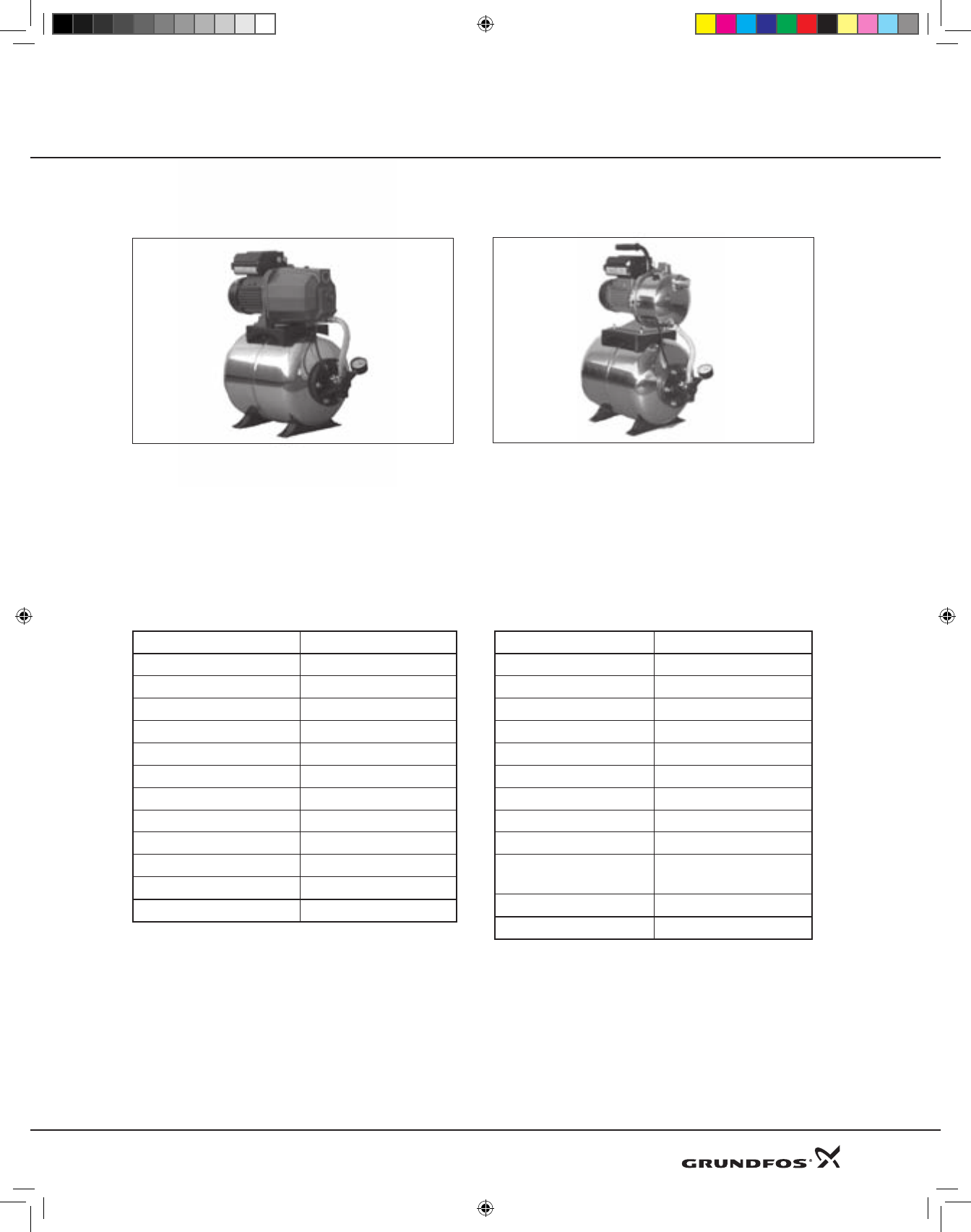
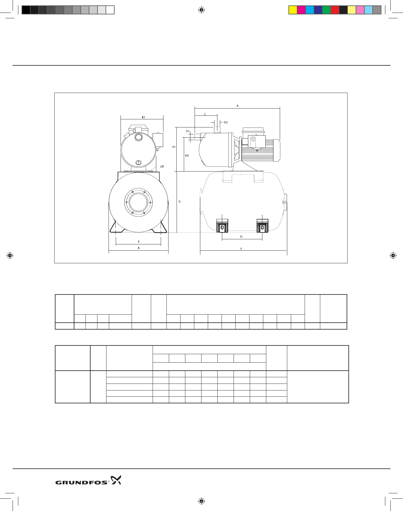
Features and Benefits
Assembled jet-pump and tank package. Available with rugged 1/2 hp cast iron pump or corrosion-resistant
stainless steel pump, mounted on a stainless steel, 6.3 gallon (24 litre) diaphragm tank.
Package comes complete with pressure switch, gauge, hose and fittings, ready for installation.
DWS Product Guide 8-09.indd 45 8/18/2009 2:32:49 PM
46
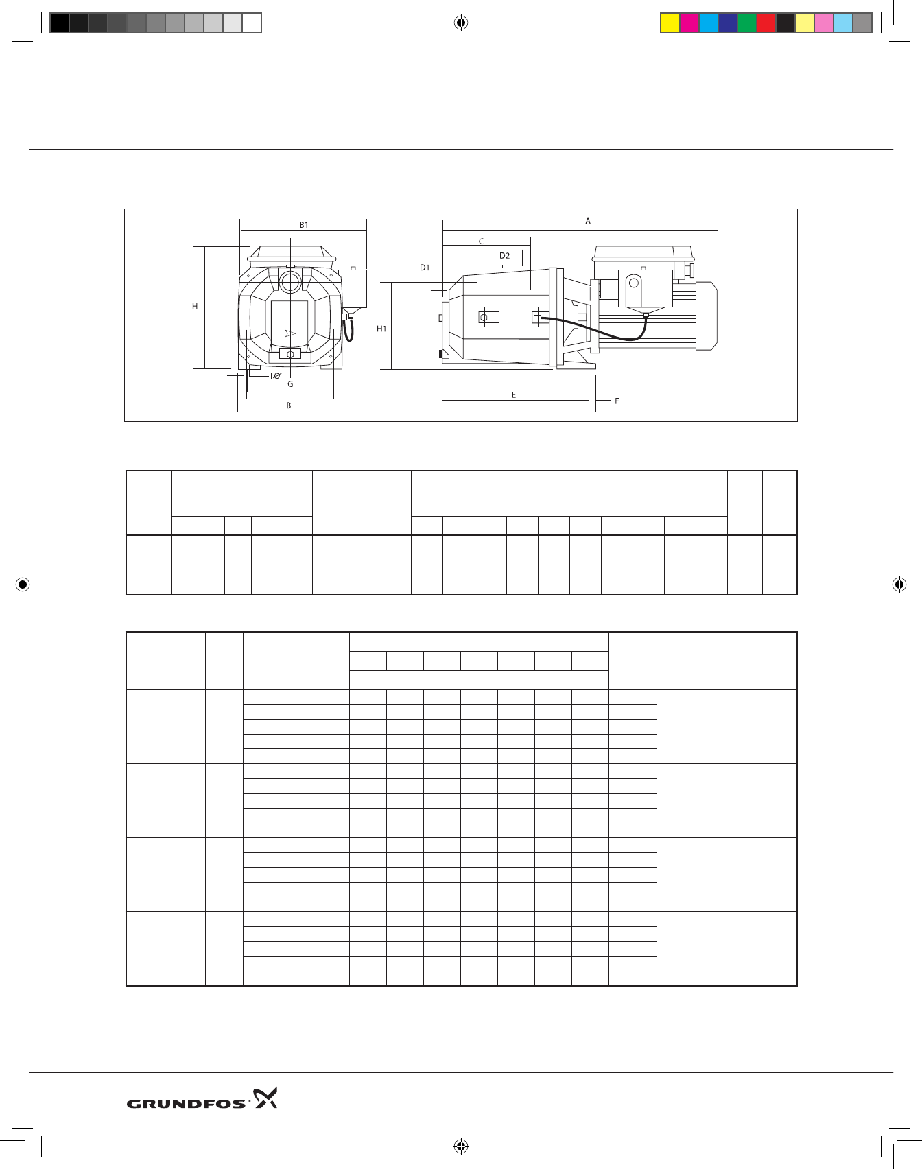
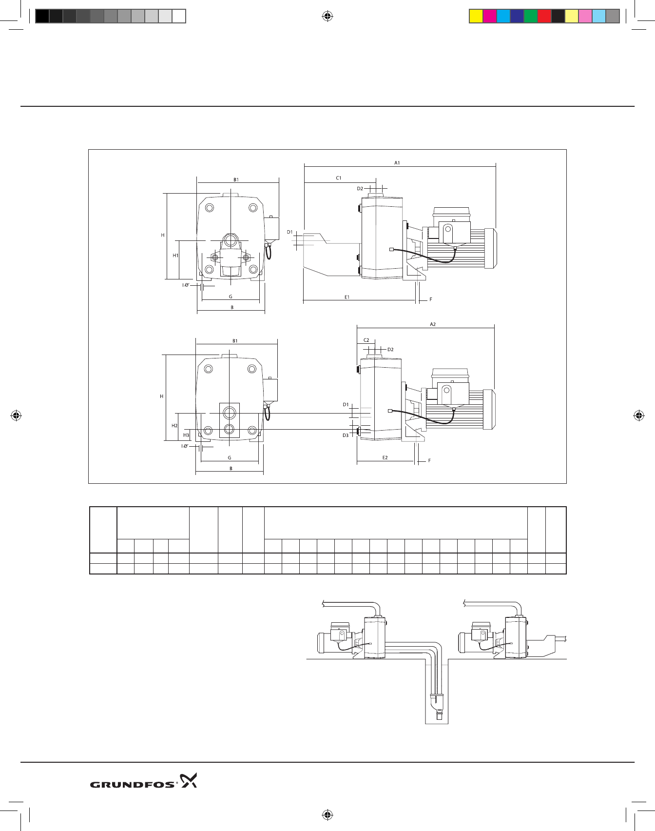
Dimensional Drawings
Dimensions and Weights
Pump
Type
Motor Data D1
Suction
NPT
D2
Disch.
NPT
Dimensions (inches) Ship
Wt.
(lbs)
Ship
Vol.
(Cu
Ft.)
HP S.F. PH Volts A B B1 C E F G H H1 IØ
JPF2A 1/3 1.75 1 115 or 230 1’’ 1’’ 16.2 7.1 9.1 5.5 8.9 0.6 5.5 8.5 6.0 0.38 35 1.5
JPF3A 1/2 1.6 1 115 or 230 1’’ 1’’ 16.2 7.1 9.1 5.5 8.9 0.6 5.5 8.5 6.0 0.38 36 1.5
JPF4A 3/4 1.5 1 115 or 230 1’’ 1’’ 17.3 7.1 9.1 5.5 8.9 0.6 5.5 8.5 6.0 0.38 41 1.5
JPF41A 1 1.4 1 115 or 230 1’’ 1’’ 17.3 7.1 9.1 5.5 8.9 0.6 5.5 8.5 6.0 0.38 43 1.5
Shallow Well Performance Chart
Model HP Depth to Water
Discharge Pressure (PSI) Shut-
off
(PSI)
Pressure Switch Settings
(PSI)
20 30 35 40 45 50 55
Capacities (U.S. gpm)*
JPF2A 1/3
5 11 7 6 4 3 2 58
20-40
10 10 7 6 4 3 2 56.5
15 9 7 6 4 3 2 54
20 7 6 5 4 3 2 51.5
25 5 4 3 2 1 49
JPF3A 1/2
5 12 11 11 10 7 6 4 73.5
30-50
10 10.5 10 10 9.5 7 6 4 71
15 9 8.5 8 8 7 6 4 68.5
20 7.5 7 7 7 6.5 6 4 66
25 5 5 5 5 4.5 4 4 63.5
JPF4A 3/4
5 15 14 14 13 10 8.5 6 75.5
30-50
10 13 12.5 12.5 12 10 8.5 6 73
15 11 11 10 10 10 8 6 70.5
20 9 9 9 8.5 8 7 6 68
25 6 6 6 6 5 5 5 65.5
JPF41A 1
5 21 20.5 20 20 20 19 17.5 86.5
40-60
10 19 18.5 18 18 17.5 17.5 17 84
15 16 16 16 15.5 15 15 14.5 81.5
20 13.5 13.5 13.5 13 13 12.5 12 79
25 10 10 10 9.5 9 9 8.5 76.5
* Capacities given are for near-sea level installations.
JPF 2A, 3A, 4A, 41A
Product Guide
DWS Product Guide 8-09.indd 46 8/18/2009 2:32:50 PM
47
Product Guide JPF 2A, 3A, 4A, 41A
* Capacities given are for near-sea level installations.
Performance curves
DWS Product Guide 8-09.indd 47 8/18/2009 2:32:50 PM
48
Dimensional Drawings
Dimensions and Weights
Pump
Type
Motor Data D1
Suction
NPT
D2
Disch.
NPT
D3
Re-
turn
NPT
Dimensions (inches) Ship
Wt.
(lbs)
Ship
Vol.
(Cu
Ft.)
HP S.F. PH Volts A1 A2 B B1 C1 C2 E1 E2 F G H H1 H2 H3 IØ
JPF5A 1.5 1.3 1 230 1-1/4’’ 1’’ 1’’ 22.0 15.3 8.3 11.0 8.7 2.0 13.8 7.8 0.78 5.7 10.0 6.2 4.3 2.1 0.44 70 1.9
JPF7A 2 1.2 1 230 1-1/4’’ 1’’ 1’’ 25.6 19.9 8.3 12.4 8.7 2.0 13.8 7.8 0.78 5.7 10.0 6.2 4.3 2.1 0.44 73 2.5
Conversion Instructions
from Shallow Well to DeepWell*
Remove bolts and detach ejector nose from
convertible jet pump. Connect suction (D1) and
pressure (D3) port to deep well ejector.
* Requires separate ejector to suit specific
suction lift needs.
JPF 5A, 7A Convertibles
Product Guide
Shallow Well
Deep Well
DWS Product Guide 8-09.indd 48 8/18/2009 2:32:50 PM
49
Shallow Well Performance Chart
Model HP Depth to Water
Discharge Pressure (PSI)
Shut-off (PSI) Pressure Switch
Settings (PSI)
20 30 35 40 45 50 55
Capacities (U.S. gpm)*
JPF5A 1-1/2
5 21 20.5 20 20 20 19 17.5 86.5
50-70
10 19 18.5 18 18 17.5 17.5 17 84
15 16 16 16 15.5 15 15 14.5 81.5
20 13.5 13.5 13.5 13 13 12.5 12 79
25 10 10 9.5 9 9 8.5 76.5
JPF7A 2
5 34 34 33.5 33 32.5 30 27 88
50-80
10 28.5 28 28 28 27.5 27 26 85.7
15 24 24 23.5 23.5 23 22.5 22 83
20 20 20 19.5 19.5 19.5 19 19 80
25 15.5 15.5 15.5 15 15 15 77.8
* Capacities given are for near-sea level installations.
Performance Curves
* Capacities given are for near-sea level installations.
Product Guide JPF 5A, 7A Convertibles
DWS Product Guide 8-09.indd 49 8/18/2009 2:32:51 PM
50
Product Guide
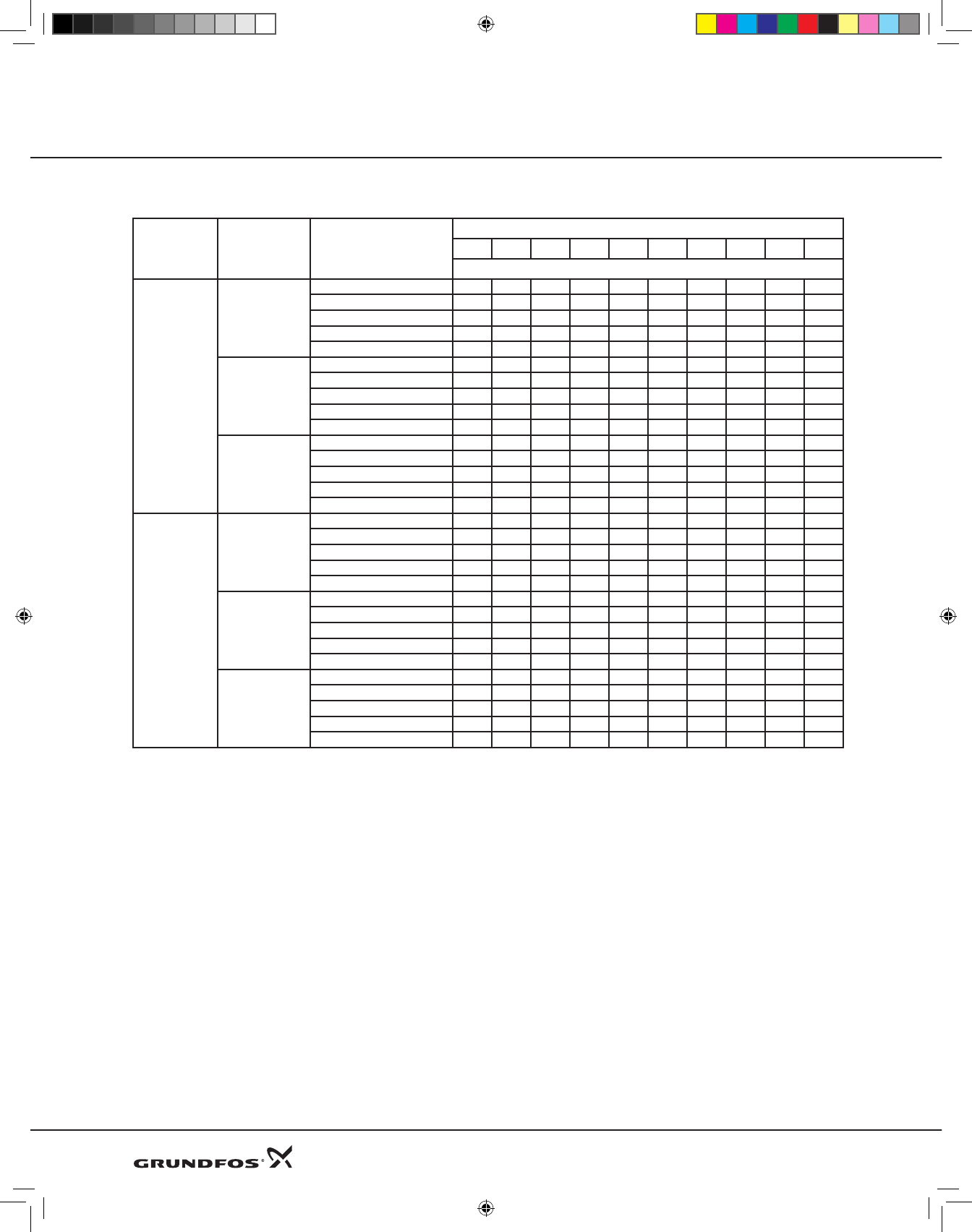
Deep Well Performance Chart
Model Ejector Type Discharge Pressure (psig)
Depth to water (feet)
30 40 50 60 70 80 90 100 120 140
Capacities U.S. gpm*
JPF5A
E20
45 14.9 13.2 11.4 9.7 7.8 6.0
50 12.1 10.2 8.4 6.7 3.9
60 9.6 7.3 5.3 3.7
65 6.0 4.1 2.1
75 2.9 1.0
E25
50 10.1 8.9 8.0 6.2 4.8
60 8.0 6.8 5.8 4.1 3.0
65 6.0 5.4 1.0
75 5.3 3.1
80 2.5 1.7
E30
50 7.4 6.7 5.9 5.0 3.2 1.5
60 6.2 5.5 4.8 4.1 2.7 1.2
65 5.1 4.5 3.9 3.1 1.4
75 4.0 3.5 2.9 2.0
80 3.1 2.7 2.2 1.8
JPF7A
E20
50 17.5 15.8 14.3 11.7 8.0 5.5 1.5
60 14.2 12.5 10.6 8.5 6.0 3.6
65 11.0 9.8 7.1 5.0 2.1
75 7.8 6.0 3.6 1.7
80 4.2 2.6
E25
50 11.9 10.5 9.3 8.0 6.1 3.8 1.0
60 9.7 8.4 7.1 5.8 4.3 3.0
65 7.6 6.3 5.2 4.0 2.2
75 5.5 4.3 3.4 2.3
90 3.6 2.6 1.8
E30
65 7.9 6.9 6.1 5.1 3.9 1.5
75 6.3 5.6 5.1 4.3 2.8 1.0
80 5.3 4.6 4.1 3.5 2.0
90 4.3 3.7 3.2 2.6 1.2
95 3.3 2.9 2.4 1.9
* Capacities given are for near-sea level installations.
JPF 5A, 7A Convertibles
DWS Product Guide 8-09.indd 50 8/18/2009 2:32:51 PM
51
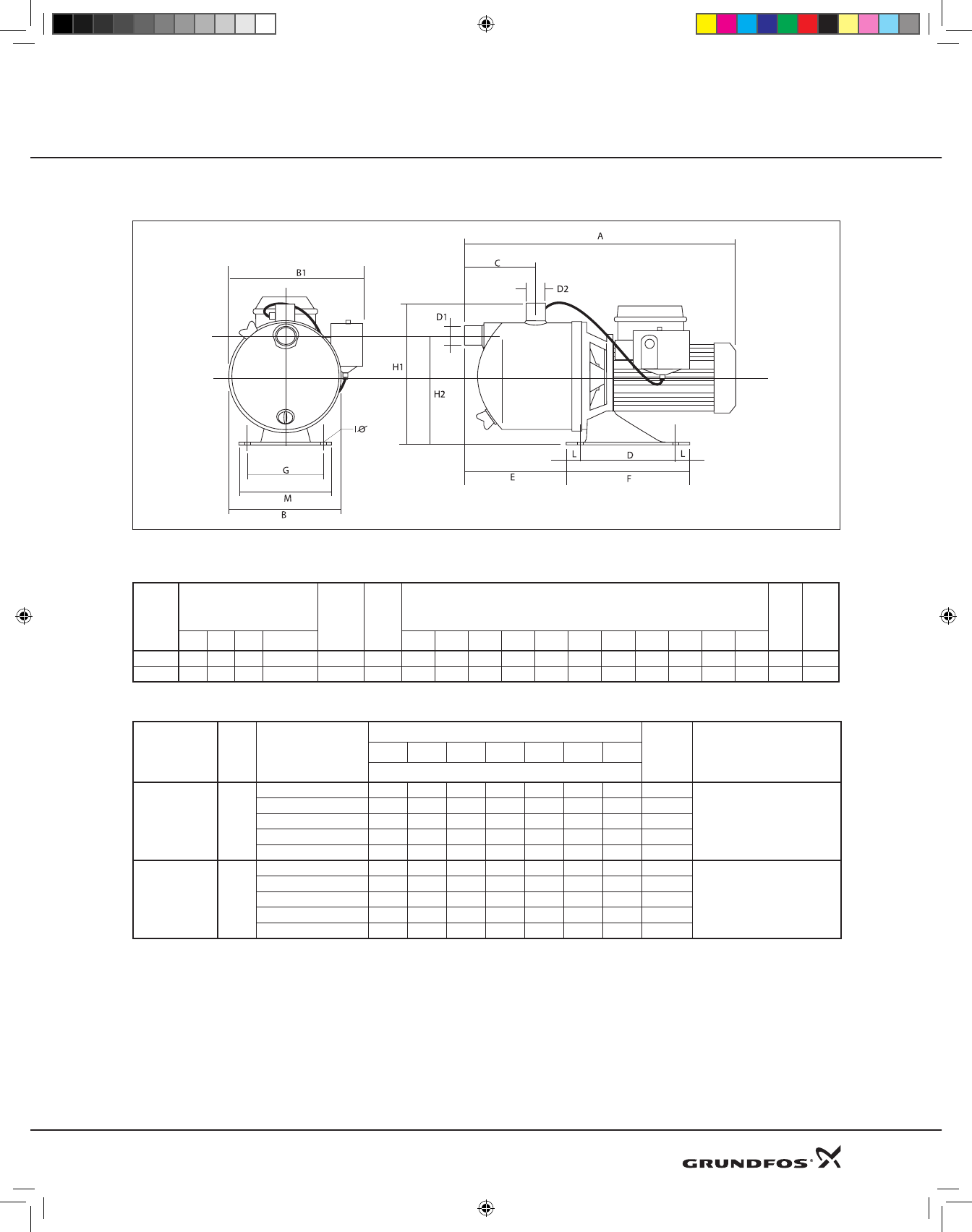
Dimensional Drawings
Dimensions and Weights
Pump
Type
Motor Data D1
Suction
NPT
D2
Disch.
NPT
Dimensions (inches) Ship
Wt.
(lbs)
Ship
Vol.
(Cu
Ft.)
HP S.F. PH Volts A B B1 C E F G H1 H2 L IØ
JPS2A 1/2 1.6 1 115 or 230 1’’ 1’’ 14.8 7.5 9.3 3.7 4.8 7.1 4.3 9.1 7.0 0.83 0.42 24 1.5
JPS4A 1 1.6 1 115 or 230 1’’ 1’’ 15.6 7.5 9.3 3.7 4.8 7.1 4.3 9.1 7.0 0.83 0.42 31 1.5
Shallow Well Performance Chart
Model HP Depth to Water
Discharge Pressure (PSI) Shut-
off
(PSI)
Pressure Switch Settings
(PSI)
20 30 35 40 45 50 55
Capacities (U.S. gpm)*
JPS2A 1/2
5 15 13 11 8 6 4 2 62
30-50
10 14 12 10 7 5 3 1 59.5
15 13 11 9 6 4 2 57
20 10 10 8 5 3 1 54.5
25 8 8 7 4 2 52
JPS4A 1
5 30 27 22 17 14 10 7 68
30-50
10 26 23 21 16 13 9 6 65.5
15 22 21 20 15 12 8 5 63
20 18 17 16 14 11 7 4 60.5
25 14 13 13 12 11 6 3 58
* Capacities given are for near-sea level installations.
Product Guide JPS 2A, 4A
DWS Product Guide 8-09.indd 51 8/18/2009 2:32:51 PM
52
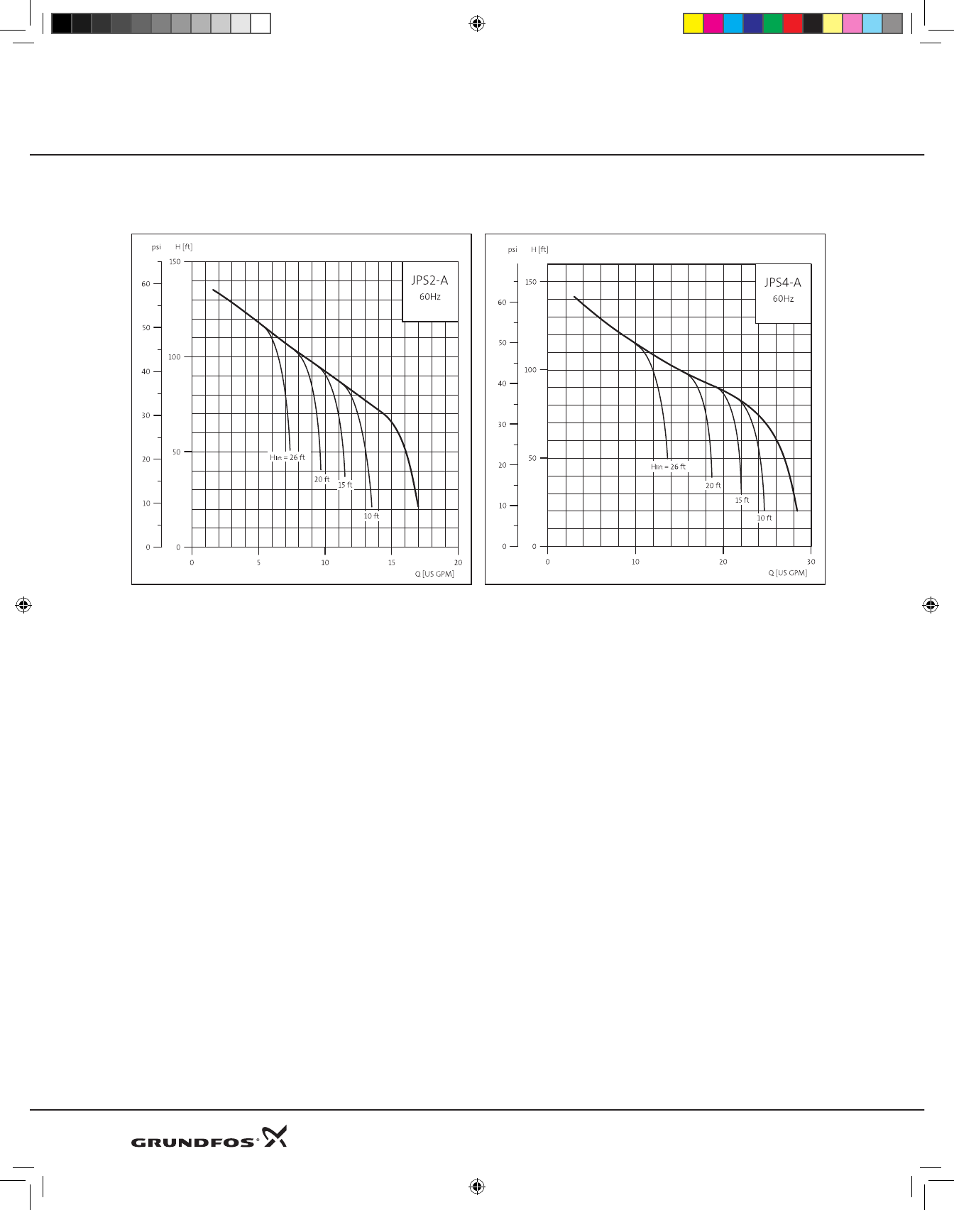
* Capacities given are for near-sea level installations.
Product Guide JPS 2A, 4A
Performance curves
DWS Product Guide 8-09.indd 52 8/18/2009 2:32:51 PM
53
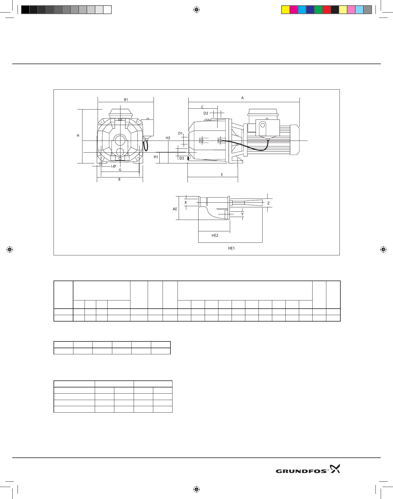
Dimensional Drawings
Dimensions and Weights
Pump
Type
Motor Data D1
Suction
NPT
D2
Disch.
NPT
D3
Return
NPT
Dimensions (inches) Ship
Wt.
(lbs)
Ship
Vol.
(Cu
Ft.)
HP S.F. PH Volts A B B1 C E IØ G H H1 H2
JDF2A 1/2 1.6 1 115 or 230 1.25’’ 1’’ 1’’ 15.2 7.1 9.1 3.5 8.0 0.38 5.5 8.9 1.9 3.6 36 1.5
JDF4A 3/4 1.5 1 115 or 230 1.25’’ 1’’ 1’’ 15.2 7.1 9.1 3.5 8.0 0.38 5.5 8.9 1.9 3.6 37 1.5
Deep Well Ejector Dimensions
AE HE1 HE2 X Y Z
3.8 11.6 5.63 1’’ NPT 1’’NPT 1.25’’NPT
Nozzle and Venturi Combinations
for Grundfos Deep Well Jet Pumps
Ejector Type Nozzle Size Venturi Size
mm. Inches mm. Inches
E20 6 0.24 12 0.48
E25 6 0.24 10 0.40
E30 6 0.24 8.5 0.34
Product Guide JDF 2A, 4A
Deep Well Ejector
DWS Product Guide 8-09.indd 53 8/18/2009 2:32:52 PM
54
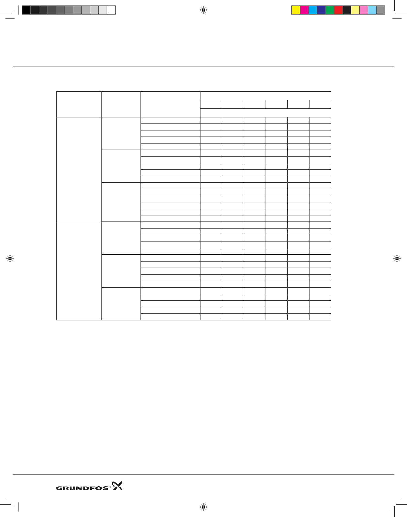
Product Guide JDF 2A, 4A
Performance Chart
Model Ejector Type Discharge Pressure (psig)
Depth to water (feet)
30 40 50 60 70 80
Capacities U.S. gpm*
JDF2A
E20
20 12.0 7.0
30 4.6
35
45
SHUTOFF (psi)
E25
20 10.4 8.5 6.5
30 5.8 4.5 2.9
35 3.8 2.5 1.1
45 1.0
SHUTOFF (psi) 0.8 0.7 0.7
E30
20 8.3 7.1 6.2 4.1 3.3
30 5.9 4.9 4.0 2.6 1.8
35 4.8 3.8 2.9 1.6
45 2.9 2.0 1.3
50 2.0 1.25
SHUTOFF (psi) 1.0 0.9 0.9
JDF4A
E20
20 18 9.0 1.6
30 8.3 2.7 0.8
35 3.4 1.0
45
SHUTOFF (psi)
E25
20 13.3 11.1 8.7
30 8.7 6.8 4.8
35 6.6 4.6 2.9
45 2.6 1.0
SHUTOFF (psi) 0.8 0.8 0.7
E30
30 6.0 5.4 4.4 3.5 2.2
35 5.3 4.3 3.3 2.6 1.8
45 3.1 2.3 1.6 1.2
50 2.2 1.5 1.0 0.5
SHUTOFF (psi) 1.2 1.0 1.0 0.9
* Capacities given are for near-sea level installations.
DWS Product Guide 8-09.indd 54 8/18/2009 2:32:52 PM

55
Product Guide JPF3A Pump Package*
Cast Iron Body Construction
*Available in Canada
Dimensional Drawings
Dimensions and Weights
Pump Type Motor Data D1
Suction
NPT
D2
Disch.
NPT
Dimensions (inches) Ship
Wt.
(lbs)
Ship
Vol.
(Cu
Ft.)
HP S.F. PH Volts A B B1 C D E F G H1
JPF3A 1/2 1.6 1 115 or 230 1’’ 1’’ 1.2 11.9 9.1 5.5 9.1 7.1 15.2 11.9 6.0 7.0 5.0
Shallow Well Performance Chart
Model HP Depth to Water
Discharge Pressure (PSI) Shut-
off
(PSI)
Pressure Switch Settings
(PSI)
20 30 35 40 45 50 55
Capacities (U.S. gpm)*
JPF3A 1/2
5 12 11 11 10 7 6 4 73.5
30-50
10 10.5 10 10 9.5 7 6 4 71
15 9 8.5 8 8 7 6 4 68.5
20 7.5 7 7 7 6.5 6 4 66
25 5 5 5 5 4.5 4 4 63.5
* Capacities given are for near-sea level installations.
DWS Product Guide 8-09.indd 55 8/18/2009 2:32:52 PM
56
Product Guide
Dimensional Drawings
Dimensions and Weights
Pump
Type
Motor Data D1
Suction
NPT
D2
Disch.
NPT
Dimensions (inches) Ship
Wt.
(lbs)
Ship Vol.
(Cu Ft.)
HP S.F. PH Volts A B B1 C E F G H1 H2 IØ
JPS2A 1/2 1.6 1 115 or 230 1’’ 1’’ 14.8 11.9 9.3 3.7 7.1 15.2 11.9 8.5 6.0 0.38 45.0 5.0
Shallow Well Performance Chart
Model HP Depth to Water
Discharge Pressure (PSI) Shut-
off
(PSI)
Pressure Switch Settings
(PSI)
20 30 35 40 45 50 55
Capacities (U.S. gpm)*
JPS2A 1/2
5 15 13 11 8 6 4 2 62
30-50
10 14 12 10 7 5 3 1 59.5
15 13 11 9 6 4 2 57
20 10 10 8 5 3 1 54.5
25 8 8 7 4 2 52
* Capacities given are for near-sea level installations.
JPS2A Pump Package*
Stainless Steel Body Construction
*Available in Canada
DWS Product Guide 8-09.indd 56 8/18/2009 2:32:52 PM

57
Submittal data sheet
56
Company name:
Prepared by:
Phone number: ( ) -
Fax number: ( ) -
Submittal Data Sheet Date: Page 1 of:
Quote number:
Project title: Client name:
Reference number: Client number:
Client contact: Client phone no: ( ) -
For: Unit:
Site: Service:
Address: City: State: Zip Code:
Technical Data Motor Information
Flow (GPM) HP:
Head (Ft) Phase:
Motor Voltage:
Max Fluid Temp Enclosure:
Min Fluid Temp
Max Working Pressure
Min Required Inlet Pressure
Connection Type and Size
Model Information from Type Key and Codes:
Quantity Required: Example: MQ 3-35
Minimum required flow: NPSH required at duty point:
Product Guide additional information pages
Materials page number: Performance curve page number:
Technical data page number: Motor data page number:
Custom-built pump information (optional):
Location Information
Client Information
Additional Information
Pump Information
Submittal data sheet
DWS Product Guide 8-09.indd 57 8/18/2009 2:32:53 PM

Grundfos Pumps Corporation
17100 W. 118th Terrace
Olathe, KS 66061
Telephone 913 227 3400
Fax: 913 227 3500
www.grundfos.com
Grundfos Canada, Inc.
2941 Brighton Road
Oakville, Ontario L6H 6C9 Canada
Telephone: 905 829 9533
Fax: 905 829 9512
Bombas Grundfos de Mexico, S.A. de C.V.
Boulevard TLC #15
Parque Stiva Aeropuerto
Apodaca, N.L. 66600 Mexico
Telephone: 52 81 8144 4000
Fax: 52 81 8144 4010
Being responsible is our foundation
Thinking ahead makes it possible
Innovation is the essence
Subject to alterations
2008, 2009 Grundfos Pumps Corp.
DWS Product Guide 8-09.indd 58 8/18/2009 2:32:53 PM
