3955 1 Zoeller 267 0057 Brochure Fm0390 266/267/268 Catalog Sheet User Manual
User Manual: Pump 3955 1 Zoeller 267-0057 Brochure
Open the PDF directly: View PDF ![]() .
.
Page Count: 2
© Copyright 2004 Zoeller Co. All rights reserved.
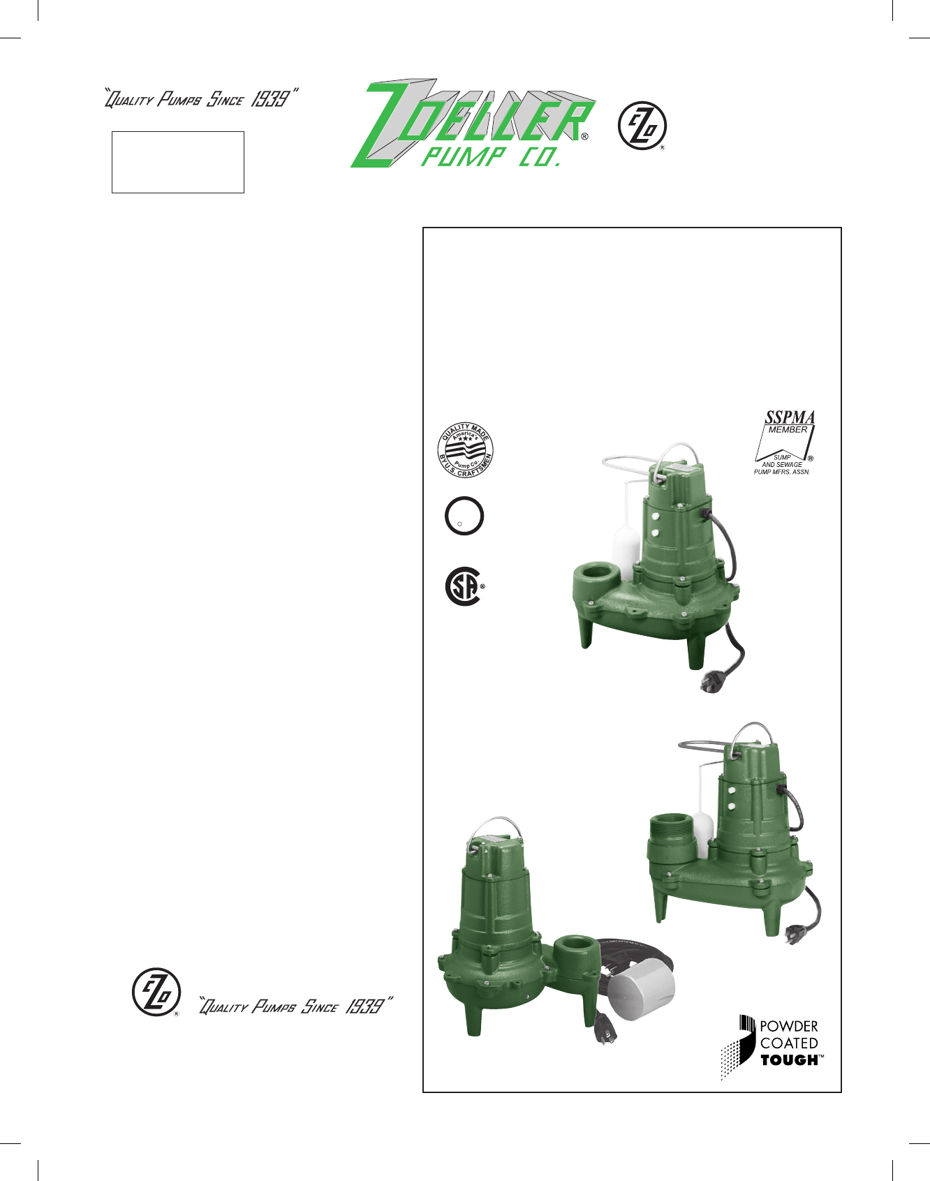
266 - 267 - 268 Series
(For Pump Prefi x Identifi cation see News & Views 0052)
“WASTE-MATE”
SUBMERSIBLE
SEWAGE/*EFFLUENT PUMP
OR DEWATERING PUMP
2” NPT DISCHARGE
FEATURES AVAILABLE
• Automatic
• Nonautomatic (for variable level systems)
• 2” NPT Discharge (2” & 3” Model 268)
• ½ HP, 1 Ph, 115V, 200-208V, or 230V
• Passes 2” Spherical Solids
• BN and BE267 pumps available packaged with a
Piggyback Variable Level Float Switch
• ½ HP, 3 Ph, 200-208V, 230V, or 460V
Automatic
“267”
COMPARE THESE FEATURES
• Float operated, submersible (NEMA 6) 2-pole
mechanical switch.
• Durable cast construction. ASTM Class 25 Cast
iron, switch case, and pump housing.
• Cast iron base on 267, 268.
• Engineered Plastic base on 266.
• Non-Clogging Vortex Impeller Design. Engineered
plastic impeller with metal inserts on models 266,
267 & 268 (1 PH). Model 267 available with cast
iron impeller option. (Cast iron impeller standard
on 3 PH models.)
• Not effected by materials normally found in
drainage and sewage sumps.
• Stainless steel screws, bolts, handle, guard, and
arm and seal assembly.
• UL Listed 3-wire neoprene cord and plug.
10 ft. cord standard for automatic.
15 ft. cord standard for Nonautomatic.
• Square Ring & Gasket - Neoprene.
• Motor - 266/267/268 Series - ½ HP 60 Hz, 1725
RPM, oil-fi lled, hermetically sealed, automatic
reset thermal overload protected (1 PH only).
• Oil lubricated bearings.
• Carbon and ceramic shaft seal.
• Passes 2-inch spherical solids.
• 2” NPT Discharge.
• Model 268 contains combination 2” NPT Female
and 3” NPT Male discharge.
• On point - 12”. Off point - 4” (Automatic units).
•
Corrosion resistant powder coated epoxy fi nish.
SECTION: 2.30.020
FM0390
0804
Supersedes
0303
Product information presented
here refl ects conditions at time
of publication. Consult factory
regarding discrepancies or
inconsistencies. MAIL TO: P.O. BOX 16347 • Louisville, KY 40256-0347
SHIP TO: 3649 Cane Run Road • Louisville, KY 40211-1961
(502) 778-2731 • 1 (800) 928-PUMP • FAX (502) 774-3624
visit our web site:
www.zoeller.com
* May be used in those states where codes do not restrict solids size in
effl uent systems.
** See back page for UL & CSA listings.
ALL MODELS ARE
COMPLETELY SUBMERSIBLE
HERMETICALLY SEALED
Watertight - dust tight.
Manufacturers of . . .
Note: The sizing of effl uent systems normally requires variable
level fl oat(s) controls and properly sized basins to achieve
required pumping cycles or dosing timers with nonautomatic
pumps.
Nonautomatic
“267”
for variable
level systems
Automatic
“268”
Tested to UL
Standard UL778
R
L
U
**
**
Certifi ed to CSA
Standard C22.2 No.108
© Copyright 2004 Zoeller Co. All rights reserved.
All installation of controls, protection devices and wiring should be done by a qualifi ed licensed
electrician. All electrical and safety codes should be followed including the most recent National
Electric Code (NEC) and the Occupational Safety and Health Act (OSHA).
For information on additional Zoeller products refer to catalog on SImplex Panels, FM1596; Piggyback
Variable Level Switches, FM0477; Electrical Alternator, FM0486; Mechanical Alternator, FM0495;
Sump/Sewage Basins, FM0487; Single Phase Alarm Systems, FM0732; Watertight Junctions Boxes,
FM1597; and Disconnect & Rail Systems, FM0787.
SELECTION GUIDE
1. Integral fl oat operated mechanical switch, no external control required.
2. For automatic use single piggyback variable level fl oat switch or double
piggyback variable level fl oat switch. Refer to FM0477.
3. See FM1228 for correct model of simplex control panel.
4. See FM0712 for correct model of duplex control panel or FM1663 for a
residential alternator system.
CONSULT FACTORY FOR SPECIAL APPLICATIONS
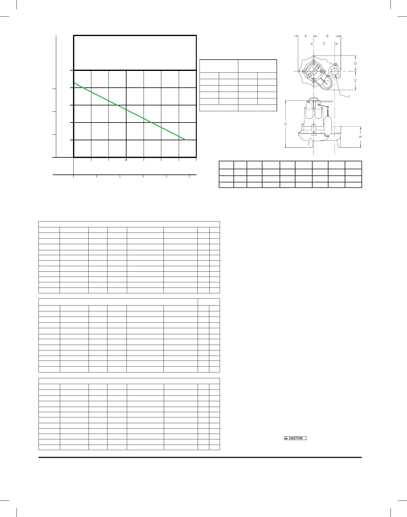
MODEL A B C D E F G H
266 4-3/4 8-5/16 6-13/32 4-3/4 6-15/32 2” NPT 14-1/32 6-3/32
267 4-3/4 8-5/16 6-13/32 4-3/4 6-15/32 2” NPT 14-9/32 6-11/32
268 4-3/4 8-13/32 6-13/32 4-3/4 6-15/32 2”/3” NPT 14-1/32 8-13/32
• Minimum recommended basin size (Small load applications)
Simplex - 18” x 30”.
Duplex - 30” x 36”.
• High water alarms available.
RESERVE POWERED DESIGN
For unusual conditions a reserve safety factor is engineered into the design of every Zoeller pump.
SK375
267 MODELS Control Selection Listings
Model Volts-Ph Mode Amps Simplex Duplex CSA UL
M267 115 1 Auto 10.4 1 4 Y Y
BN267 115 1 Auto 10.4 ** 4 Y Y
N267 115 1 Non 10.4 2 or 3 2 or 4 Y Y
D267 230 1 Auto 5.5 1 --- Y Y
E267 230 1 Non 5.5 2 or 3 4 Y Y
** BE267 230 1 Auto 5.5 ** --- Y Y
* H267 200-208 1 Auto 6.2 1 --- N N
* I267 200-208 1 Non 6.2 3 4 N N
* J267 200-208 3 Non 2.6 3 4 N Y
* F267 230 3 Non 2.6 3 4 N Y
* G267 460 3 Non 1.5 3 4 N N
**
268 MODELS Control Selection Listings
Model Volts-Ph Mode Amps Simplex Duplex CSA UL
M268 115 1 Auto 10.4 1 4 Y Y
** BN268 115 1 Auto 10.4 ** 4 Y Y
N268 115 1 Non 10.4 2 or 3 2 or 4 Y Y
D268 230 1 Auto 5.5 1 --- Y Y
E268 230 1 Non 5.5 2 or 3 4 Y Y
** BE268 230 1 Auto 5.5 ** --- Y Y
* H268 200-208 1 Auto 6.2 1 --- Y N
* I268 200-208 1 Non 6.2 3 4 Y N
* J268 200-208 3 Non 2.6 3 4 Y Y
* F268 230 3 Non 2.6 3 4 Y Y
* G268 460 3 Non 1.5 3 4 N N
*No molded plug **Single piggyback switch included
266 MODELS Control Selection Listings
Model Volts-Ph Mode Amps Simplex Duplex CSA UL
M266 115 1 Auto 10.4 1 4 Y Y
** BN266 115 1 Auto 10.4 ** 4 Y Y
N266 115 1 Non 10.4 2 or 3 2 or 4 Y Y
D266 230 1 Auto 5.5 1 --- Y Y
E266 230 1 Non 5.5 2 or 3 4 Y Y
** BE266 230 1 Auto 5.5 ** --- Y Y
* H266 200-208 1 Auto 6.2 1 --- N N
* I266 200-208 1 Non 6.2 3 4 N N
* J266 200-208 3 Non 2.6 3 4 N Y
* F266 230 3 Non 2.6 3 4 N Y
* G266 460 3 Non 1.5 3 4 N N • For “M” and “D” models, the approximate gallons pumped out per cycle
are:
Tank Diameter Gallons Pumped
18” Simplex 8 Gallons
24” Simplex 15 Gallons
30” Duplex 22 Gallons
36” Duplex 33 Gallons
48” Duplex 60 Gallons
Caution: Maximum temperature of sewage or dewatering must be limited to
130°F (54°C). For over 130°F (54°C) special quotation required.
Standard All Models -
266 - Weight 41 lbs. ½ HP.
267 - Weight 47.5 lbs. ½ HP.
268 - Weight 51 lbs. ½ HP.
5
10
15
20
25
0
2
4
6
LITERS
GALLONS
FLOW PER MINUTE
METERS
FEET
TOTAL DYNAMIC HEAD
0 100
20 40
200
60
300
80 100
400
120
500
140
PUMP PERFORMANCE CURVE
MODEL 266/267/268
013225A
013225B
MODEL
Meters Liters
266/267/268
54841.5 128
10 3373.0 89
15 1894.6 50
20 386.1 10
Shut-off Head: 21.5 ft.(6.6m)
Feet Gal.
TOTAL DYNAMIC HEAD/FLOW
PER MINUTE
SEWAGE AND DEWATERING
