537324 2 Grundfos Magna3 Owners Manual User
537304 2 Grundfos Magna3 Owners Manual 537304_2_Grundfos Magna3 Owners Manual 537304_2_Grundfos Magna3 Owners Manual pdf pumpproducts
537308 2 Grundfos Magna3 Owners Manual 537308_2_Grundfos Magna3 Owners Manual 537308_2_Grundfos Magna3 Owners Manual pdf pumpproducts
537302 2 Grundfos Magna3 Owners Manual 537302_2_Grundfos Magna3 Owners Manual 537302_2_Grundfos Magna3 Owners Manual pdf pumpproducts
537314 2 Grundfos Magna3 Owners Manual 537314_2_Grundfos Magna3 Owners Manual 537314_2_Grundfos Magna3 Owners Manual pdf pumpproducts
537307 2 Grundfos Magna3 Owners Manual 537307_2_Grundfos Magna3 Owners Manual 537307_2_Grundfos Magna3 Owners Manual pdf pumpproducts
User Manual: Pump 537324 2 Grundfos Magna3 Owners Manual
Open the PDF directly: View PDF ![]() .
.
Page Count: 64
- 1. Product introduction
- 2. Performance range
- 3. Product range
- 4. Identification
- 5. Construction
- 6. Operating conditions
- 7. Installation
- 8. Functions
- 9. Guide to performance curves
- 10. Performance curves and technical data
- 11. Accessories
- 12. Further product information
GRUNDFOS DATA BOOKLET
MAGNA3
Circulator pumps
60 Hz

Table of contents
2
MAGNA3
1. Product introduction 3
Features and benefits 3
Applications 3
2. Performance range 4
MAGNA3 4
MAGNA3 D single-head operation 5
MAGNA3 D twin-head operation 6
3. Product range 7
Pump selection 7
4. Identification 9
Type key 9
5. Construction 10
Sectional drawing 10
Mechanical construction 11
Motor and electronic controller 11
Pump connections 11
Surface treatment 11
6. Operating conditions 12
Pumped liquids 12
General recommendations 12
Temperatures 12
Pressures 12
Differential pressure and temperature sensor 13
7. Installation 14
Mechanical installation 14
Electrical installation 14
8. Functions 19
System application 19
Functions 26
Operating modes 27
Control modes 27
Additional features for control modes 30
Setting values for control modes 32
Additional operating modes for multi-pump setup 33
Readings and settings on the pump 33
Communication 36
9. Guide to performance curves 40
Curve conditions 40
QR code on pump nameplate 41
10. Performance curves and technical data 42
MAGNA3 32-60 F (N) 42
MAGNA3 32-100 F (N) 43
MAGNA3 40-80 F (N) 44
MAGNA3 40-120 F (N) 45
MAGNA3 40-180 F (N) 46
MAGNA3 50-80 F (N) 47
MAGNA3 50-150 F (N) 48
MAGNA3 65-120 F (N) 49
MAGNA3 65-150 F (N) 50
MAGNA3 D 65-150 F 51
MAGNA3 80-100 F 52
MAGNA3 D 80-100 F 53
MAGNA3 100-120 F 53
MAGNA3 D 100-120 F 55
Technical data 56
11. Accessories 57
Insulating for air-conditioning and cooling systems 57
CIM modules 57
Grundfos GO Remote 58
12. Further product information 59
WebCAPS 59
WinCAPS 60
GO CAPS 61
Product introduction
MAGNA3 1
3
1. Product introduction
The Grundfos MAGNA3 circulator pumps are designed
for circulating liquids in the following systems:
• heating systems
• air-conditioning and cooling systems
• domestic hot water systems
• ground source heat pump systems
• solar heating systems.
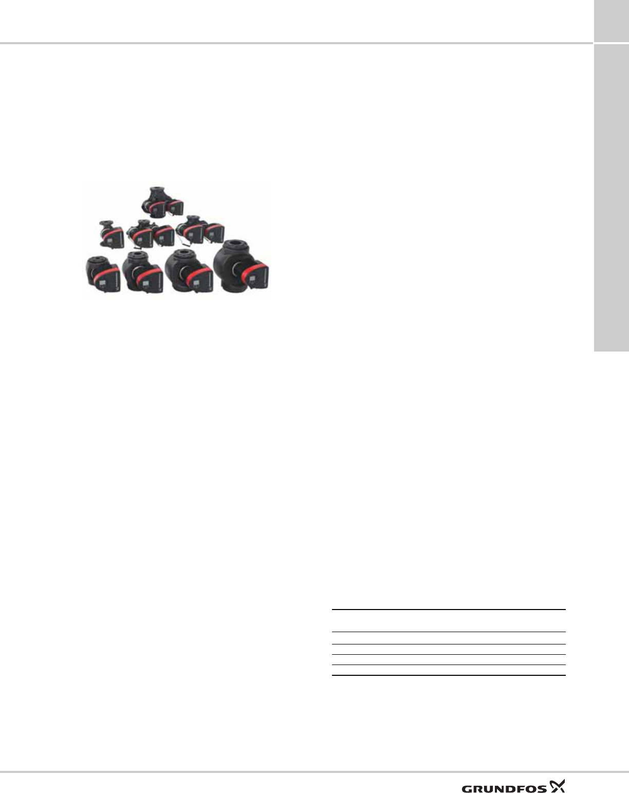
Fig. 1 MAGNA3 pump ranges
Features and benefits
Features
•AUTO
ADAPT.
•FLOW
ADAPT and FLOWLIMIT.
• Intuitive user interface with TFT display.
• Proportional pressure control.
• Constant pressure control.
• Constant temperature control.
• Built-in Grundfos differential pressure and
temperature sensor.
• Constant curve duty.
• Max. or min. curve duty.
• Automatic Night Setback.
• Internal motor protection.
• Heat energy meter.
• Work log history.
• Insulating shells supplied with single-head pumps
for heating systems.
• Large temperature range where the liquid
temperature and the ambient temperature are
independent of each other.
Benefits
• Unparalleled energy efficiency.
• Safe selection.
• Simple installation.
• Maintenance free.
• Guided installation.
• Simple assisted troubleshooting.
• Easy system optimization.
• Multi-pump function.
• External control and monitoring enabled via add-on
modules.
• No external motor protection required.
• The complete range is available for a maximum
system pressure of 175 psi (12 bar).
Applications
Heating systems
• Main pump.
• Mixing loops.
• Domestic hot water.
• Heating surfaces.
• Air-conditioning surfaces.
The MAGNA3 circulator pumps are designed for
circulating liquids in systems with variable flows where
it is desirable to optimize the setting of the pump duty
point, thus reducing energy costs.
The pump is especially suitable for installation in
existing systems where the differential pressure across
the pump is too high in periods with reduced flow
demand.
The pump is also suitable for new systems where
automatic adjustment of pump head to actual flow
demand is desired, without using expensive bypass
valves or similar components.
Furthermore, the pump is suitable for systems with hot
water priority as an external signal can immediately
force the pump to operate according to the max. curve,
for example in solar heating systems.
Duty range
TM05 7660 1413
Data MAGNA3 (N)
Single-head pumps MAGNA3 D
Twin-head pumps
Max. flow rate, Q 346 gpm (78.5 m3/h) 570 gpm (150 m3/h)
Max. head, H 60 ft (18 m)
Max. system pressure 175 psi (12 bar) (1.2 MPa)
Liquid temperature +14 to +230 °F (-10 to +110 °C)
Performance range
MAGNA3
2
4
2. Performance range
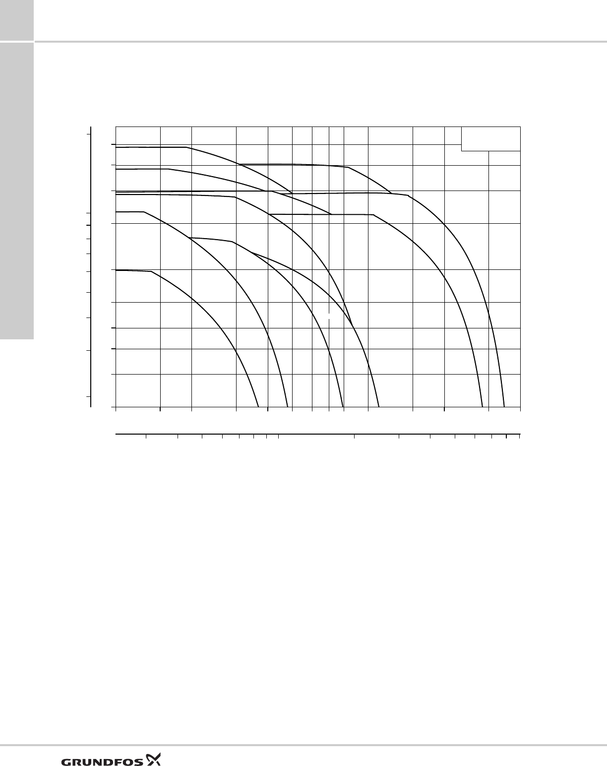
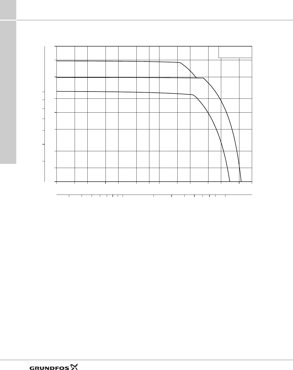
MAGNA3
Fig. 2 Performance range, MAGNA3
TM05 7654 1413
10 15 20 30 40 50 60 70 80 100 150 200 300 400
Q [US GPM]
6
8
10
12
15
20
30
40
50
60
[ft]
H
3 4 5 6 7 8 9 1010 20 30 40 50 60
Q [m³/h]
2
3
4
5
6
7
8
9
1010
[m]
H
MAGNA3
65-120
50-150
40-120
50-80
40-80
40-180
32-100
32-60
65-150
100-120
80-100
Performance range
MAGNA3 2
5
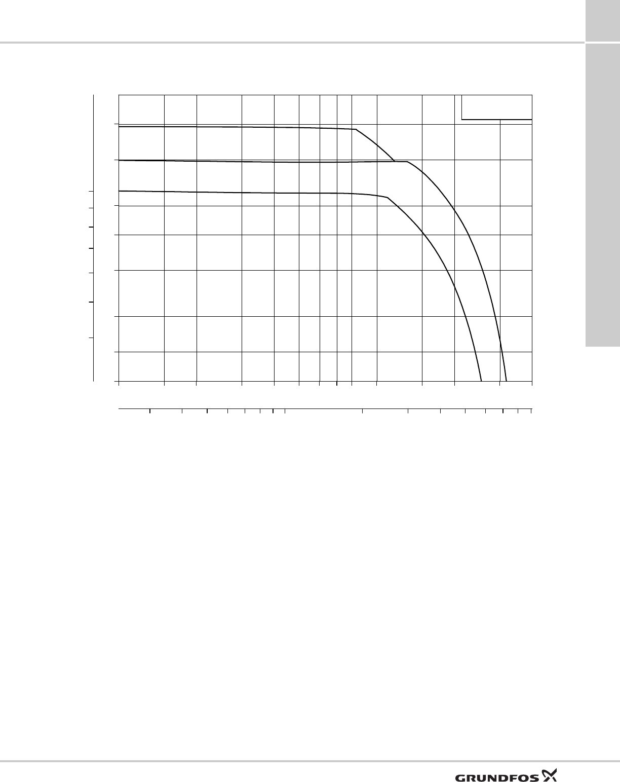
MAGNA3 D single-head operation
Fig. 3 Performance range, MAGNA3 D single-head operation
TM05 7655 1413
10 15 20 30 40 50 60 70 80 100 150 200 300 400
Q [US GPM]
10
12
15
20
25
30
40
50
[ft]
H
3 4 5 6 7 8 9 1010 20 30 40 50 60
Q [m³/h]
4
5
6
7
8
9
1010
[m]
H
MAGNA3 D
65-150
100-120
80-100
Performance range
MAGNA3
2
6
MAGNA3 D twin-head operation
Fig. 4 Performance range, MAGNA3 D twin-head operation
TM05 3938 1812
10 15 20 30 40 60 80 100100 150 200 300 400 600 800
Q [US GPM]
10
12
15
20
25
30
40
50
[ft]
H
3 4 5 6 7 8 9 1010 20 30 40 50 60 70 80 100100
Q [m³/h]
4
5
6
7
8
9
1010
[m]
H
MAGNA3 D
65-150
100-120
80-100
Product range
MAGNA3 3
7
3. Product range
Pump selection
Frequently, pumps are selected based on a maximum
flow and pressure loss in a system as well as peak
efficiency of the pump. For circulators in variable
demand systems such as a heating system where the
heat load varies with the season and time of day it is
more optimal to select a pump for this varying demand
rather than one specific duty point.
The MAGNA3 has been optimized for variable demand
systems. For variable loads, when possible it is most
ideal to size and select the pump such that the
maximum flow and pressure required is on the right
hand side of the pump performance curve.
This enables the pump to have higher efficiency at
partial load and allows the pumps to slow down more
at these partial loads yielding significant energy
savings.
Pump size
The system characteristic is used together with the
pump’s performance curve for sizing and correct pump
selection.
The selection of pump size should be based on the
following:
• required maximum flow
• maximum pressure loss in the system.
Refer to the system characteristics to determine the
duty point. See fig. 5.
Fig. 5 System characteristic
Operating conditions
When selecting a pump, always verify the operating
conditions are fulfilled. Refer to section Guide to
performance curves on page 40 for:
• liquid quality and temperature
• ambient conditions
• minimum inlet pressure
• maximum operating pressure.
Single-head pump Cast iron Stainless steel (N) Page reference
115 V 208-230 V 115 V 208-230 V
MAGNA3 32-60 F (N) 98126820 98126822 42
MAGNA3 32-100 F (N) 98126824 98126826 43
MAGNA3 40-80 F (N) 98126800 98126828 98126802 98126830 44
MAGNA3 40-120 F (N) 98126804 98126832 98126806 98126834 45
MAGNA3 40-180 F (N) 98126808 98126836 98126810 98126838 46
MAGNA3 50-80 F (N) 98126812 98126840 98126814 98126842 47
MAGNA3 50-150 F (N) 98126816 98126844 98126818 98126846 48
MAGNA3 65-120 F (N) 98124696 98126848 98124702 98126850 49
MAGNA3 65-150 F (N) - 98126852 - 98126854 50
MAGNA3 80-100 F (N) - 98126856 - 98126858 52
MAGNA3 100-120 F (N) - 98126860 - 98126862 54
MAGNA3 D 65-150 F - 98126863 - - 51
MAGNA3 D 80-100 F - 98126864 - - 53
MAGNA3 D 100-120 F - 98126865 - - 55
TM02 2040 3301
Q
Duty point
H
Product range
MAGNA3
3
8
Control modes
•AUTO
ADAPT (factory setting): Is suitable for most
installations. Auto adapt is proportional pressure
control where the pump sets and adapts its own set
point based on maximum system conditions.
•FLOW
ADAPT, FLOWLIMIT: in systems where a flow
limitation is required.
• Proportional pressure control in systems with
considerable pressure loss variation in relation to
large flow variations; i.e. if more than 50 % of
pressure loss is due to friction loss in the pipe
system.
• Constant pressure control in systems with
insignificant pressure loss variation in relation to
large flow variations; i.e. if less than 50 % of
pressure loss is due to friction loss in the pipe
system
• Constant temperature control in heating systems
with a fixed system characteristic, for example
domestic hot water systems.
• Constant curve duty.
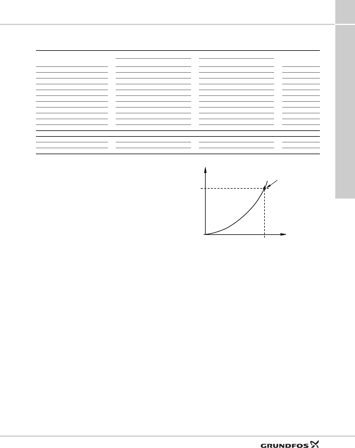
Determination of precise setpoint
To determine precise setpoint for proportional pressure
control, consult WebCAPS (www.grundfos.us/
WebCAPS). See fig. 6.
The desired proportional pressure setpoint can be
determined by selecting the duty point on the pump
curve. In the upper right hand corner, the setpoint can
be read.
In order to see the setpoint, in CAPS on the product
detail page, select:
Options>Curve settings>Curve types>Check local
control>Proportional pressure.
Fig. 6 Grundfos WebCAPS tool
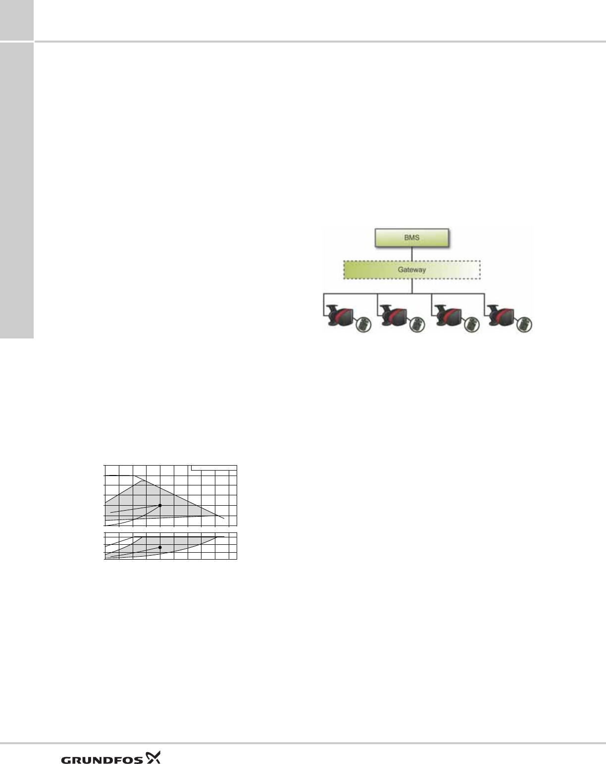
Communication
The Grundfos CIM modules (CIM = Communication
Interface Module) enable the MAGNA3 to connect to
standard fieldbus networks, offering substantial
benefits:
• complete process control and monitoring
• modular design, prepared for future requirements
• based on standard functional profiles
• simple configuration and easy installation
• open communication standards
• reading warning and alarm indications.
For further details, see section CIM modules on
page 37.
Fig. 7 Example of typical building management system
(BMS)
Note: A gateway is a device that facilitates the transfer
of data between two different networks based on
different communication protocols.
TM05 8778 2713
[m]
H
2
4
6
8
0
0 5 10 15 20 25 30 35 40
200
400
0
[W]
P1
Q [m³/h]
TM05 2710 1112

Identification
MAGNA3 4
9
4. Identification
Type key
Code Example MAGNA3 (D) 100 -120 (F) (N) 360
Type range
MAGNA3
D
Single-head pump
Twin-head pump
Nominal diameter (DN) of suction and discharge ports [mm]
Maximum head [dm]
F
Pipe connection
Flange
N
Pump housing material
Cast iron
Stainless steel
Port-to-port length [mm]
Construction
MAGNA3
5
10
5. Construction
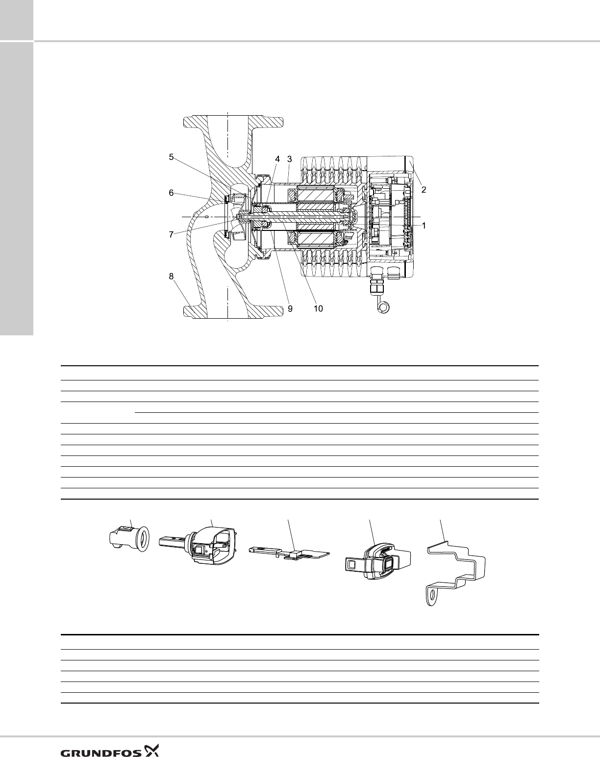
Sectional drawing
Fig. 8 MAGNA3
Material specification
Fig. 9 Sensor
TM05 2319 0312
Pos. Component Material
1 Outer bearing ring Aluminium oxide
2 Control box Polycarbonate
3Stator housing Aluminium
O-rings EPDM
4 Thrust bearing Aluminium oxide/carbon
5 Bearing plate Stainless steel (304)
6 Neck ring Stainless steel (304)
7 Impeller PES
8 Pump housing Cast iron/stainless steel (316)
9 Rotor can PPS
10 Shaft Stainless steel (316L)
TM05 3035 0812
Pos. Component Material
1 Sealing cap EPDM
2 Housing PPS
3 Printed-circuit board -
4 Cover snap-on PA/TPV
5 Bracket for sensor Stainless steel
1
2
345

Construction
MAGNA3 5
11
Mechanical construction
The MAGNA3 is of the canned-rotor type, i.e. pump
and motor form an integral unit without shaft seal and
with only two gaskets for sealing. The bearings are
lubricated by the pumped liquid.
The pump is characterized by the following:
• controller integrated in the control box
• control panel on the control box
• control box prepared for optional CIM modules
• built-in differential pressure and temperature sensor
• cast-iron or stainless-steel pump housing
• twin-head versions
• no external motor protection required
• insulating shells supplied with single-head pumps
for heating systems.
Motor and electronic controller
The MAGNA3 incorporates a 4-pole synchronous,
permanent magnet motor (PM motor). This motor type
is characterized by higher efficiency than a
conventional asynchronous squirrel cage motor.
The pump speed is controlled by an integrated variable
frequency drive.
A differential pressure and temperature sensor is
incorporated in the pump.
Pump connections
See individual product pages.
Surface treatment
The pump housing and pump head are electrocoated
to improve the corrosion resistance.
Electrocoating includes:
• alkaline cleaning
• pretreatment with zinc phosphate coating
• cathodic electrocoating (epoxy)
• curing of paint film at +392 to +482 °F (+200 to +250
°C).
Color
Color codes for the pump:
Color Code
Red NCS40-50R
Black NCS9000

Operating conditions
MAGNA3
6
12
6. Operating conditions
Pumped liquids
The pump is suitable for thin, clean, non-aggressive
and non-explosive liquids, not containing solid
particles or fibers that may attack the pump
mechanically or chemically.
In heating systems, the water should meet the
requirements of accepted standards on water quality in
heating systems.
In domestic hot water systems, we recommend to use
MAGNA3 pumps only for water with a degree of
hardness lower than approx. 14 °dH.
In domestic hot water systems, we recommend to keep
the liquid temperature below +149 °F (+65 °C) to
eliminate the risk of lime precipitation.
The MAGNA3 pumps can be used for pumping
water/glycol mixtures up to 50 %.
Example of a water/ethylene glycol mixture:
Maximum viscosity: 50 cSt ~ 50 % water / 50 %
ethylene glycol mixture at +14 °F (-10 °C).
The pump is controlled by a power-limiting function
that protects against overload.
The pumping of glycol mixtures will affect the max.
curve and reduce the performance, depending on the
water/ethylene glycol mixture and the liquid
temperature.
To prevent the ethylene glycol mixture from degrading,
avoid temperatures exceeding the rated liquid
temperature and minimize the operating time at high
temperatures.
It is important to clean and flush the system before the
ethylene glycol mixture is added.
To prevent corrosion or lime precipitation, check and
maintain the ethylene glycol mixture regularly. If further
dilution of the supplied ethylene glycol is required,
follow the glycol supplier's instructions.
General recommendations
Temperatures
Liquid temperature
Ambient temperature
Pressures
Maximum operating pressure
175 psi (12 bar).
Minimum inlet pressure
The following relative minimum pressure must be
available at the pump inlet during operation to avoid
cavitation noise and damage to the pump bearings.
The values in the table below apply to single-head
pumps and twin-head pumps in single-head operation.
In the case of twin-head operation, the required
relative inlet pressure must be increased by 1.45 psi
(0.1 bar) compared to the stated values for single-head
pumps or twin-head pumps in single-head operation.
Note: Actual inlet pressure plus pump pressure
against a closed valve must be lower than the
maximum permissible system pressure.
The relative minimum inlet pressures apply to pumps
installed up to 984 ft (300 m) above sea level. For
altitudes above 984 ft (300 m), the required relative
inlet pressure must be increased by 1.45 psi per 330 ft
(0.1 bar / 0.01 MPa per 100 m) altitude. The MAGNA3
pump is only approved for an altitude of 6560 ft
(2000 m).
Water in heating
systems Water quality according to local standards
Domestic hot water Degree of hardness up to 14 °dH
Water containing
glycol Maximum viscosity = 50 cSt ~ 50 % water /
50 % ethylene glycol at +14 °F (-10 °C)
Application Temperature range
General +14 to +230 °F (-10 to +110 °C)
Domestic hot water systems +150 °F (Up to +65 °C)
recommended
Ambient conditions
Ambient temperature during
operation +32 to +140 °F (0 to +40 °C)
Ambient temperature during
storage and transport -40 to +158 °F (-40 to +70 °C)
Relative air humidity Maximum 95 %
MAGNA3
DN
Liquid temperature
[167 °F (75 °C)] [203 °F (95 °C)] [230 °F (110 °C)]
Inlet pressure [psi (bar)]
32-60/100 1.5 (0.10) 5.0 (0.35) 14.5 (1.0)
40-80 1.5 (0.10) 7.3 (0.50) 16.0 (1.1)
40-120/
150/180 1.5 (0.10) 5.8 (0.40) 14.5 (1.0)
50-80 1.5 (0.10) 1.5 (0.10) 10.2 (0.7)
50-150 2.9 (0.20) 8.7 (0.60) 17.4 (1.2)
65-120 1.5 (0.10) 7.3 (0.50) 16.0 (1.1)
65-150 5.8 (0.40) 11.6 (0.80) 17.4 (1.2)
80-100 7.3 (0.50) 13.1 (0.90) 21.8 (1.5)
100-120 7.3 (0.50) 13.1 (0.90) 21.8 (1.5)

Operating conditions
MAGNA3 6
13
Differential pressure and
temperature sensor
The MAGNA3 incorporates a differential pressure and
temperature sensor. The sensor is located in the pump
housing in a channel between the suction and
discharge ports. The sensors of twin-head pumps are
connected to the same channel and the pumps
therefore register the same differential pressure and
temperature.
Via a cable, the sensor sends an electrical signal for
the differential pressure across the pump and for the
liquid temperature to the controller in the control box.
In case of missing sensor signal, the pump will run at
maximum speed. When the fault has been corrected,
the pump will continue operating according to the
parameters set.
The differential pressure and temperature sensor
offers substantial benefits:
• direct feedback on the pump display
• complete pump control
• measurement of the pump workload for precise and
optimum control resulting in higher energy
efficiency.
Installation
MAGNA3
7
14
7. Installation
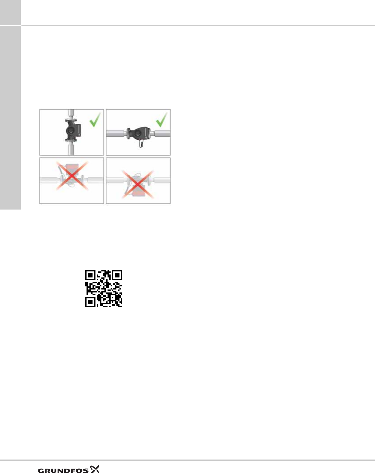
Mechanical installation
The MAGNA3 is designed for indoor installation.
The pump must be installed with horizontal motor
shaft.
The pump may be installed in horizontal as well as
vertical pipes.
Fig. 10 Installation positions
Arrows on the pump housing indicate the liquid flow
direction through the pump.
The control box must be in horizontal position with the
Grundfos logo in vertical position. See fig. 10.
This is described in the installation and operating
instructions.
The pump must be installed in such a way that it is not
stressed by the pipework.
The pump may be suspended direct in the pipes,
provided that the pipework can support the pump.
Twin-head pumps are prepared for installation on a
mounting bracket or base plate.
To ensure adequate cooling of motor and electronics,
the following must be observed:
• Position the pump in such a way that sufficient
cooling is ensured.
• The temperature of the ambient air must not exceed
+104 °F (+40 °C).
Insulating shells
The insulating shells supplied with single-head
MAGNA3 pumps are for heating systems and should
be fitted as part of the installation.
Insulating shells for air-conditioning and cooling
systems are available as an accessory.
For cooling systems, see section Insulating for
air-conditioning and cooling systems, page 57.
Note: Insulating shells are not available for twin-head
pumps.
Electrical installation
The electrical connection and protection should be
carried out in accordance with local regulations.
• The pump must be connected to an external mains
switch.
• The pump must always be correctly earthed.
• The pump requires no external motor protection.
• The pump incorporates thermal protection against
slow overloading and blocking.
• When switched on via the power supply, the pump
will start pumping after approx. 5 seconds.
Note: The number of starts and stops via the power
supply must not exceed four times per hour.
The pump has a digital input that can be used for
external control of start/stop without switching the
power supply on/off.
The pump mains connection must be made as shown
in the diagrams on the following pages.
Cables
Use screened cables for external on/off switch, digital
input, sensor and setpoint signals.
• All cables used must be heat-resistant up to at least
+185 °F (+85 °C).
• All cables used must be installed in accordance with
EN 60204-1 and EN 50174-2:2000.
TM05 2866 0712
http://GRUNDFOS.COM/MANUAL-MAGNA3
Installation
MAGNA3 7
15
Additional protection
If the pump is connected to an electric installation
where an earth leakage circuit breaker (ELCB) is used
as an additional protection, this circuit breaker must
trip when earth fault currents with DC content
(pulsating DC) occur.
The earth leakage circuit breaker must be marked with
the first or both of the symbols as shown:
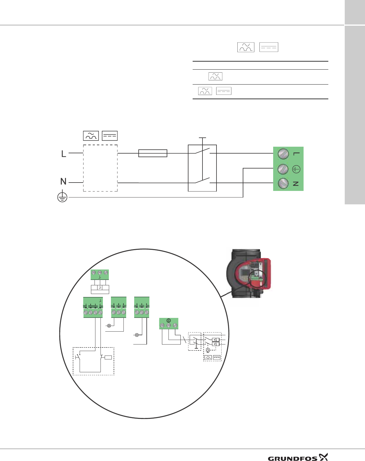
Examples of connections
Supply connection
Fig. 11 Example of typical connection, 1 x 230 V ± 10 %, 50/60 Hz
As a minimum, a 10 A time-lag fuse must be installed
due to the start-up power of the MAGNA3.
Connection to external controllers
Fig. 12 Example of connections in the control box
Symbol Description
High-sensitivity ELCB, type A, according to
IEC 60775
High-sensitivity ELCB, type B, according to
IEC 60775
TM03 2397 0312
External switch
Fuse
(min. 10 A, time lag)
ELCB
TM05 2673 3812
NC NO C NC NO C
NL
S/S
M
I
M
A
signal
sensor
Vcc
24V IN
Mains connection
Alarm
Operation
Start/stop On/off timer
Analog input
Installation
MAGNA3
7
16
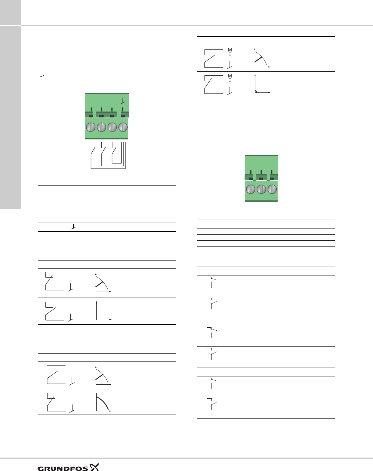
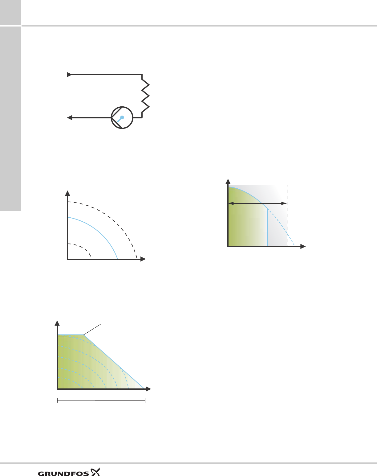
Digital inputs
The digital input can be used for external control of
start/stop or forced max. or min. curve.
Note: If no external on/off switch is connected, the
jumper between terminals Start/Stop (S/S) and frame
( ) should be maintained. This connection is the
factory setting.
Fig. 13 Digital input in control box
External start/stop
The pump can be started or stopped via the digital
input.
External forced max. or min curve
The pump can be forced to operate on the max. or min.
curve via the digital input.
Relay outputs
The pump has two signal relays with a potential-free
changeover contact for external fault indication.
The function of the signal relay can be set to "Alarm",
"Ready" or "Operation" on the pump control panel or
with the Grundfos GO Remote.
Fig. 14 Relay output in control box
The functions of the signal relays are as shown in the
table below:
TM05 3343 1212
Contact symbol Function
M
AMax. curve
M
IMin. curve
S/S Start/Stop
Frame connection
Start/stop
Normal duty
Stop
Max. curve
Normal duty
Max. curve
S/S
M
I
M
A
S/S
Q
H
S/S
Q
H
M
A
Q
H
M
A
Q
H
Min. curve
Normal duty
Min. curve
TM05 3343 1212
Contact symbol Function
NC Normally closed
NO Normally open
CCommon
Signal relay Alarm signal
Not activated:
• The power supply has been switched off.
• The pump has not registered a fault.
Activated:
• The pump has registered a fault.
Signal relay Ready signal
Not activated:
• The pump has registered a fault and is unable to
run.
Activated:
• The pump has been set to stop, but is ready to run.
• The pump is running.
Signal relay Operating signal
Not activated:
• The pump is not running.
Activated:
• The pump is running.
Q
H
Q
H
NC N0 C
132
NC NO C
132
NC NO C
12 3
NC NO C
132
NC NO C
132
NC NO C
12 3
NC NO C
132
NC NO C
132
NC NO C
12 3
NC NO C

Installation
MAGNA3 7
17
Analog input for external sensor
The analog input can be used for the connection of an
external sensor for measuring temperature, pressure,
flow or other parameter.
The analog input can also be used for an external
signal for the control from a BMS system or similar
control system.
The electrical signal for the input can be 0-10 VDC or
4-20 mA.
The selection of electrical signal (0-10 V or 4-20 mA)
can be changed on the control panel or with the
Grundfos GO Remote.
Fig. 15 Analog input for external sensor or control
In order to optimize the pump performance, external
sensors can advantageously be used in the following
cases:
Fig. 16 Wiring, analog input
Fig. 17 Examples of external sensors
For further details, see section Guide to performance
curves, page 40.
Fig. 18 Example of external signal for the control via BMS
or PLC
TM05 3221 1112
Function/control mode Sensor type
Heat energy meter Temperature sensor
Constant temperature Temperature sensor (external)
Constant pressure remote Pressure sensor (external)
TM06 0882 1114
PIN Description Load
IN Analog input 150 Ω (4-20 mA signal)
78k Ω (0-10 V signal)
24 V 24 V supply to external sensor Max. 22 mA
Ground for external sensor
signal
sensor
Vcc
24V
I
N
-+
Sensor
Sensor
TM05 2947 1212
Pos. Sensor type
1
Differential pressure transmitter,
Grundfos type DPI V.2
1/2" connection and 4-20 mA signal.
2
Relative pressure transmitter,
combined pressure and temperature sensor, Grundfos
type RPI/T G 1/2" connection and 4-20 mA signal.
TM05 2888 0612
24V
IN
Vcc Signal
1
2
24V
BMS
PLC
Installation
MAGNA3
7
18
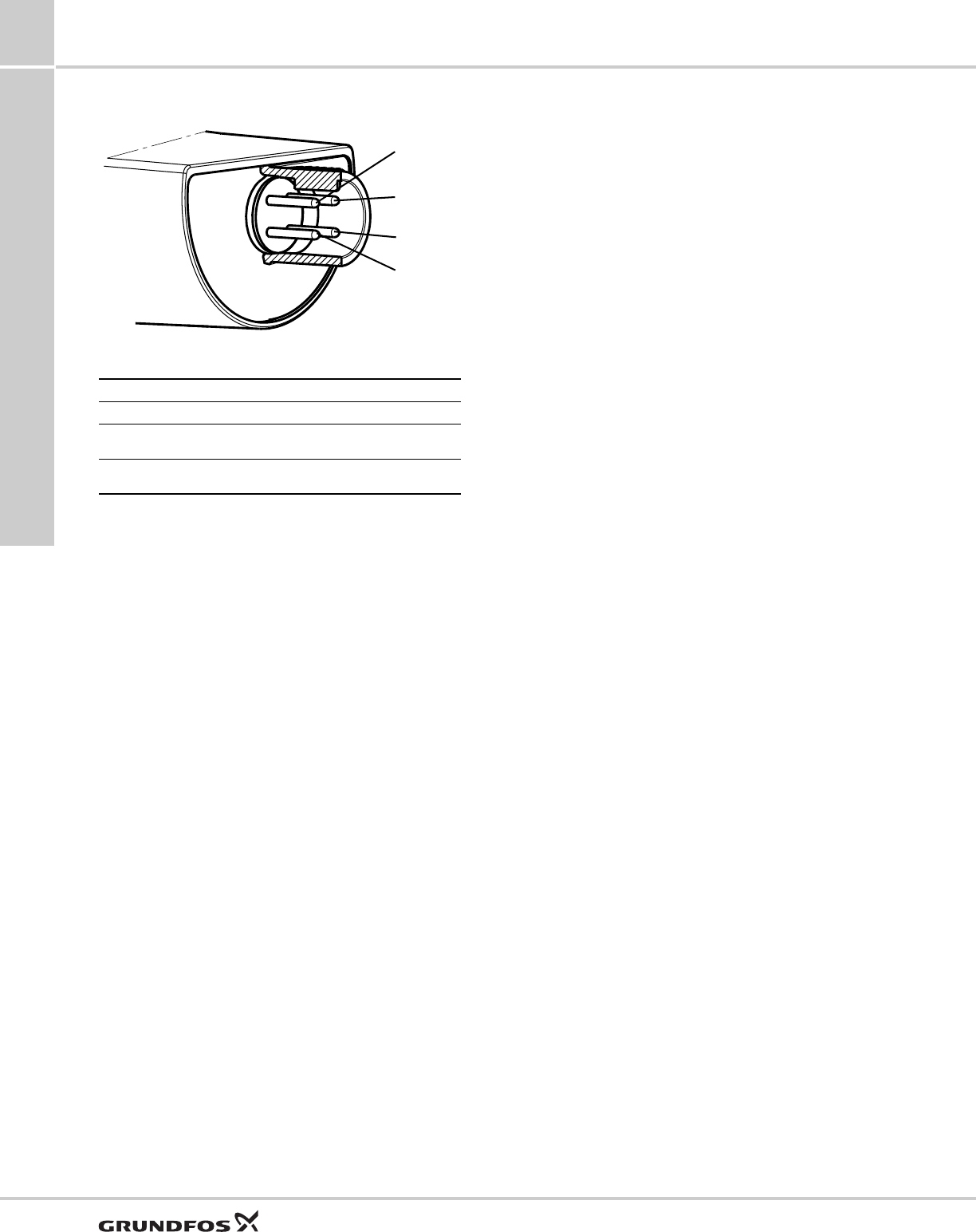
Electrical connection for external sensor
Fig. 19 Example electrical connections for external sensor
* Common ground for both pressure and temperature signal.
* Power supply (screened cable): SELV or PELV.
TM04 7156 1610
PIN 123 4
Wire color Brown Grey Blue Black
Output
4 to 20 mA + not used - not used
Output
2 x 0 to 10 V +Pressure
signal -* Temperature
signal
1
3
4
2
Functions
MAGNA3 8
19
8. Functions
System application
Heating systems
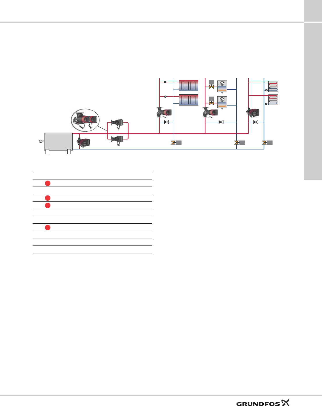
Fig. 20 Functional drawing of a heating system in a commercial building
Main pumps
Due to variations in the heat demand and water flow
rate, we always recommend to use speed-controlled
MAGNA3 pumps in a heating system, either
single-head pumps connected in parallel or twin-head
pumps. Single-head pumps connected in parallel have
several advantages. In alternating operation, each
pump is sized for 100 % flow. In this operating mode,
the second pump functions as back-up for higher
reliability. As the pumps alternate, an equal number of
operating hours is ensured. Cascade operation of
pumps connected in parallel meets demands in
high-flow systems with low differential temperature
(Δt), and 50 % back-up is ensured at the same time.
The twin-head pump saves installation time and costs.
By speed-controlling all pumps, it is possible to obtain
maximum energy saving as the pumps will run at their
best efficiency point (BEP).
In a variable-flow system, we recommend to control
main pumps in proportional pressure or AUTOADAPT
mode with a differential pressure sensor in the flow
pipe with the lowest pressure. This ensures maximum
energy saving.
By using the FLOWADAPT function to ensure correct
balancing of the system, the need for pump throttling
valves can be reduced significantly.
The built-in heat energy meter allows monitoring of the
heat energy consumption in the system for pure
optimisation purposes.
Air handler heating coils
The performance of heating surfaces is controlled by
the heating-water temperature and flow. For this
purpose, we recommend to install variable-flow mixing
loops at the heating surfaces. A speed-controlled
mixing-loop pump is ideal for adaptation to the varying
load in a heating surface. In this case, the MAGNA3
will have full authority, making external pump throttling
valves superfluous.
Domestic hot water
For domestic hot water circulation, the constant
temperature control mode will ensure a constant
temperature in the recirculation pipe, without the use
of separate thermostatic valves, thus obtaining the
maximum comfort.
TM05 2155 1312
M M
M
M
M
Pos. Description
Main pumps
ABoiler
Air handler heating coils
Domestic hot water
BHot water circulation
CCold water
Mixing loops
DRadiators
EFan coils
FUnderfloor heating
1
2
3
4

Functions
MAGNA3
8
20
Mixing loops
Due to variations in use, flow temperature and heat
demand in different parts of the building, the heating
system should be divided into zones controlled by
independent mixing loops. Due to the flow variations, a
speed-controlled mixing-loop pump will have the
authority in the system. This will help obtain a better
hydraulic balance in the total system. Speed control of
the pump via selection of a control mode, depending
on system application, ensures maximum energy
saving. See section Selection of control mode, page
24.
Advantages of using mixing loops:
• Reduced excessive differential pressure in the
system and hereby reduced risk of overflow.
• Increased control ability as the loop is provided with
the exact flow and temperature demand.
Functions
MAGNA3 8
21
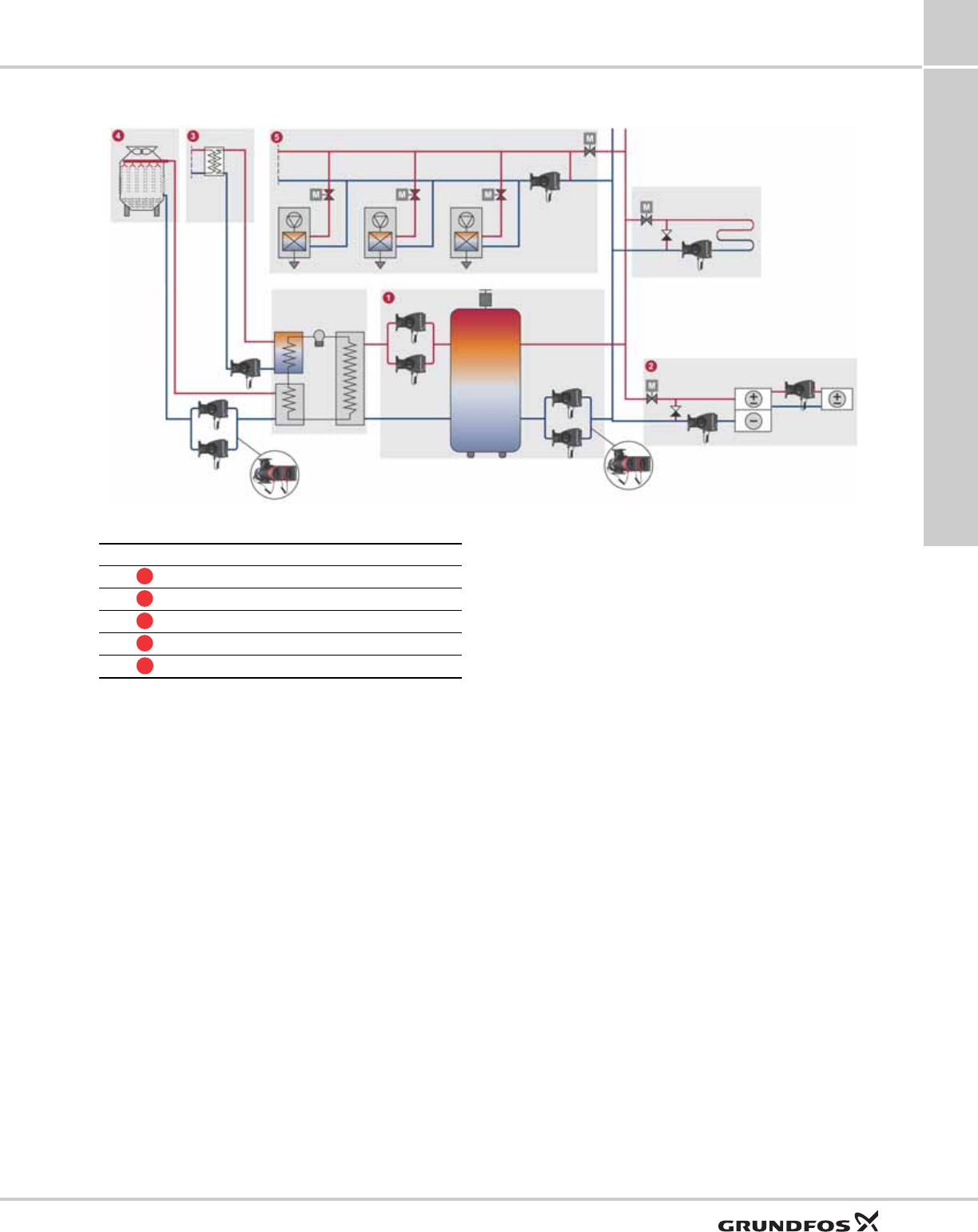
Cooling systems
Fig. 21 Functional drawing of a cooling system in a commercial building
Primary and secondary pumps
Due to variations in the cooling demand and water flow
rate, we recommend to use speed-controlled MAGNA3
pumps in a cooling system, either single-head pumps
connected in parallel or twin-head pumps. Single-head
pumps connected in parallel have several advantages.
In alternating operation, each pump is sized for 100 %
flow. In this operating mode, the second pump
functions as back-up for higher reliability. As the
pumps alternate, an equal number of operating hours
is ensured. Cascade operation of pumps connected in
parallel meets demands in high-flow systems with low
differential temperature (Δt), and 50 % back-up is
ensured at the same time.
The twin-head pump saves installation time and costs.
By speed-controlling all pumps, it is possible to obtain
maximum energy saving as the pumps will run at their
best efficiency point (BEP).
In a variable-flow system, we recommend to control
secondary pumps in proportional pressure or
AUTOADAPT mode with a differential pressure sensor
in the flow pipe with the lowest pressure. This ensures
maximum energy saving.
The built-in heat energy meter allows monitoring of the
heat energy consumption in the system.
Air handler cooling coils
The performance of cooling surfaces is controlled by
the cooling-water temperature and flow. For this
purpose, we recommend to install variable-flow mixing
loops at the cooling surfaces. A speed-controlled
mixing-loop pump is ideal for adaptation to the varying
load in a cooling surface. In this case, the MAGNA3
will have full authority, making external pump throttling
valves superfluous. The FLOWLIMIT ensures that the
rated flow is never exceeded.
Heat recovery system
The heat recovery system is of paramount importance
for the overall energy efficiency of an air-conditioning
or cooling system. Pumps used for this purpose should
be controlled by a setpoint from the building
management system. Due to high load and
temperature variations in the system, it is important to
use variable-speed pumps in a heat recovery system.
Cooling tower
Due to chiller load variations and changes in the
temperature and moisture of the ambient air, the
cooling-tower flow rate is continuously changing. In
order to achieve maximum energy saving,
cooling-tower pumps have to be able to adapt to these
varying conditions. The pumps are controlled by a
temperature setpoint which is measured at the chiller’s
condenser. In this system, the MAGNA3 will have full
authority, making pump throttling valves superfluous.
The FLOWLIMIT ensures that the rated flow is never
exceeded.
TM05 2156 1312
Pos. Description
Primary and secondary pumps
Air handler cooling coils
Heat recovery system
Cooling tower
Mixing loops
1
2
3
4
5

Functions
MAGNA3
8
22
Mixing loops
Due to the risk of condensation, the flow temperature
through a cooling ceiling or floor must never be lower
than the dew point temperature of the indoor air. The
dew point temperature is varying due to variations in
indoor moisture load and outdoor thermal conditions.
The result is that the cooling-water setpoint has to be
controlled. A mixing loop is ideal for obtaining the
correct temperature in order to adapt to the varying
setpoint.
Due to continuous cooling-load variations in the
building cooling zones, the cooling performance in
cooling ceilings and floors is controlled by motor
valves via zone control units, and a speed-controlled
mixing-loop pump should always be used.
Functions
MAGNA3 8
23
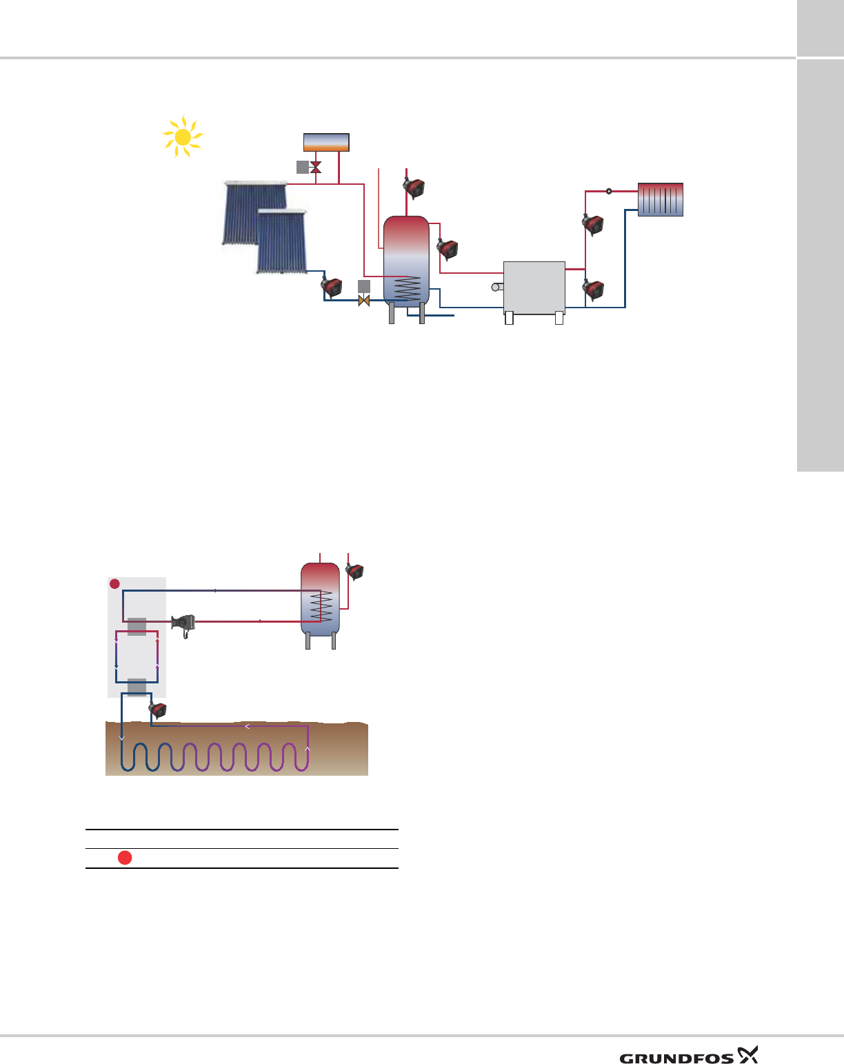
Solar heating systems
Fig. 22 Functional drawing of a solar heating system
Main pumps
Solar heating systems operate with very low flows
compared to other heating systems, however, with
relatively large pressure losses. With a conventional
circulator pump, the flow must be minimized with a
valve resulting in a significantly higher power
consumption. To achieve major reductions in power
consumption, the MAGNA3 is optimized with the
FLOWADAPT / FLOWLIMIT control mode for operation
specifically under these conditions.
Ground source heat pump systems (GSHP)
Fig. 23 Ground source heat pump system in a commercial
building
Main pump
The MAGNA3 is optimized for operation as circulator
pump in a closed-loop pipe system which is buried in
the ground and filled with a mixture of water and
antifreeze. The MAGNA3 is therefore ideal for large
ground source heat pump systems for commercial
buildings.
The MAGNA3 is designed for pumping liquids down to
+14 °F (-10 °C). It can cope with all known antifreeze
compositions.
It is very important that all components are highly
energy-efficient. No other circulator pump performs
better in GSHP systems than the MAGNA3 with the
FLOWADAPT / FLOWLIMIT control mode.
Use the benefit of the inputs/outputs of the MAGNA3 to
control the pump together with the heat pump.
Installation and commissioning
When installing MAGNA3, no external pressure sensor
or motor protection is required. Installation is simple
thanks to the built-in differential pressure and
temperature sensor, which enables proportional
pressure control without the installation of a sensor in
the system.
In systems where a differential pressure is desired at a
certain point of the system, an external pressure
sensor must be installed.
Pump selection is based on required flow and
calculated pressure losses. We recommend not to
oversize the pump as it will lead to unnecessarily high
energy consumption.
The MAGNA3 features the FLOWLIMIT function. In
circuits where the MAGNA3 has full authority, the need
for external pump throttling valves is reduced. The
FLOWLIMIT ensures that the rated flow is never
exceeded.
TM05 3421 1312
M
M
TM05 3422 1312
Pos. Description
Heat pump
1
1
Functions
MAGNA3
8
24
Selection of control mode
System application Select this control mode
Recommended for most heating systems, especially in systems with relatively large
pressure losses in the distribution pipes. See description under proportional
pressure.
In replacement situations where the proportional pressure duty point is unknown.
The duty point has to be within the AUTOADAPT operating range. During operation,
the pump automatically makes the necessary adjustment to the actual system
characteristic.
This setting ensures minimum energy consumption and noise level from valves,
which reduces operating costs and increases comfort.
AUTOADAPT
The FLOWADAPT control mode is a combination of AUTOADAPT and FLOWLIMIT.
This control mode is suitable for systems where a maximum flow limit, FLOWLIMIT, is
desired. The pump continuously monitors and adjusts the flow, thus ensuring that the
selected FLOWLIMIT is not exceeded.
Main pumps in boiler applications where a steady flow through the boiler is required.
No extra energy is used for pumping too much liquid into the system.
In systems with mixing loops, the control mode can be used to control the flow in
each loop.
Benefits:
• The dimensioned flow for each zone (required heat energy) is determined by the
flow from the pump. This value can be set precisely in the FLOWADAPT control
mode without the use of pump throttling valves.
• When the flow is set lower than the balancing valve setting, the pump will ramp
down instead of losing energy by pumping against a balancing valve.
• Cooling surfaces in air-conditioning systems can operate at high pressure and low
flow.
•Note: The pump cannot reduce the flow on the suction side, but is able to control
that the flow on the discharge side is at least the same as on the suction side. This
is due to the fact that the pump has no built-in valve.
FLOWADAPT
In systems with relatively large pressure losses in the distribution pipes and in
air-conditioning and cooling systems.
• Two-pipe heating systems with thermostatic valves and
– very long distribution pipes
– strongly throttled pipe balancing valves
– differential pressure regulators
– large pressure losses in those parts of the system through which the total
quantity of water flows (for example boiler, heat exchanger and distribution pipe
up to the first branching).
• Primary circuit pumps in systems with large pressure losses in the primary circuit.
• Air-conditioning systems with
– heat exchangers (fan coils)
– cooling ceilings
– cooling surfaces.
Proportional pressure
In systems with relatively small pressure losses in the distribution pipes.
• Two-pipe heating systems with thermostatic valves and
– dimensioned for natural circulation
– small pressure losses in those parts of the system through which the total
quantity of water flows (for example boiler, heat exchanger and distribution pipe
up to the first branching) or
– modified to a high differential temperature between flow pipe and return pipe
(for example district heating).
• Underfloor heating systems with thermostatic valves.
• One-pipe heating systems with thermostatic valves or pipe balancing valves.
• Primary circuit pumps in systems with small pressure losses in the primary circuit.
Constant pressure
H
Q
H
Q
Qmax
90 %
Hauto_min
H
fac
Qfac
H
Q
Hset
Hset
2
H
Q
Functions
MAGNA3 8
25
In heating systems with a fixed system characteristic, for example domestic hot
water systems, the control of the pump according to a constant return-pipe
temperature may be relevant.
FLOWLIMIT can be used with advantage to control the maximum circulation flow.
Constant temperature
Select this control mode if the pump performance is to be controlled according to a
differential temperature in the system where the pump is installed.
This control mode requires two temperature sensors, either the internal temperature
sensor together with an external sensor or two external sensors.
Differential temperature
If an external controller is installed, the pump is able to change from one constant
curve to another, depending on the value of the external signal.
The pump can also be set to operate according to the max. or min. curve, like an
uncontrolled pump:
• The max. curve mode can be used in periods in which a maximum flow is
required. This operating mode is for instance suitable for hot water priority.
• The min. curve mode can be used in periods in which a minimum flow is required.
This operating mode is for instance suitable for manual night setback if Automatic
Night Setback is not desired.
Constant curve
In systems with pumps operating in parallel.
The multi-pump function enables the control of single-head pumps connected in
parallel (two pumps) and twin-head pumps without the use of external controllers.
The pumps in a multi-pump system communicate with each other via the wireless
GENIair connection.
"Assist" menu
Multi-pump setup
System application Select this control mode
H
Q
H
Q
Δt
H
Q

Functions
MAGNA3
8
26
Functions
Page
Operating modes
Normal (control modes enabled) 27
Stop 27
Min. curve 27
Max. curve 27
Control modes
AUTOADAPT (factory setting) 27
FLOWADAPT 28
Proportional pressure 28
Constant pressure 28
Constant temperature 29
Differential temperature 29
Constant curve 29
Additional features for control modes
FLOWLIMIT 30
Automatic Night Setback 31
Additional operating modes for multi-pump setup
Alternating operation 33
Back-up operation 33
Cascade operation 33
Readings and settings on the pump
Control panel and display 33
Operating status 35
Pump performance 35
Warning and alarm 35
Heat energy meter 35
Work log history 35
Input for external sensor 36
Grundfos Eye (status indicator) 36
Communication
Wireless Grundfos GO Remote 36
Wireless GENIair connection 37
Pump information to BMS via CIM modules 37
Digital inputs 36
Relay outputs 36
Analog input 36
Bus via GENIbus 38
Bus via LonWorks 38
Bus via PROFIBUS DP 38
Bus via Modbus RTU 38
Bus via BACnet MS/TP 38
Grundfos Remote Management 38
Functions
MAGNA3 8
27
Operating modes
Fig. 24 Max. or min. curves
Normal: The pump runs according to the selected
control mode.
Note: The control mode and setpoint can be selected
even if the pump is not running in "Normal" mode.
Stop: The pump stops.
Min.: The min. curve mode can be used in periods in
which a minimum flow is required.
This operating mode is for instance suitable for manual
night setback if Automatic Night Setback is not
desired.
Max.: The max. curve mode can be used in periods in
which a maximum flow is required.
This operating mode is for instance suitable for hot
water priority.
The operating modes can be selected directly by use
of the built-in digital inputs. See section Digital inputs,
page 16.
Control modes
Factory setting
The pumps have been factory-set to AUTOADAPT
without Automatic Night Setback.
The setpoint has been factory-set. See section Setting
values for control modes, page 32.
The factory setting is suitable for most installations.
Note: When switched on via the power supply, the
pump will start in AUTOADAPT after approx. 5 seconds.
If the buttons on the control panel are not touched for
15 minutes, the display will go into sleep mode. When
a button is touched, the "Home" display will appear.
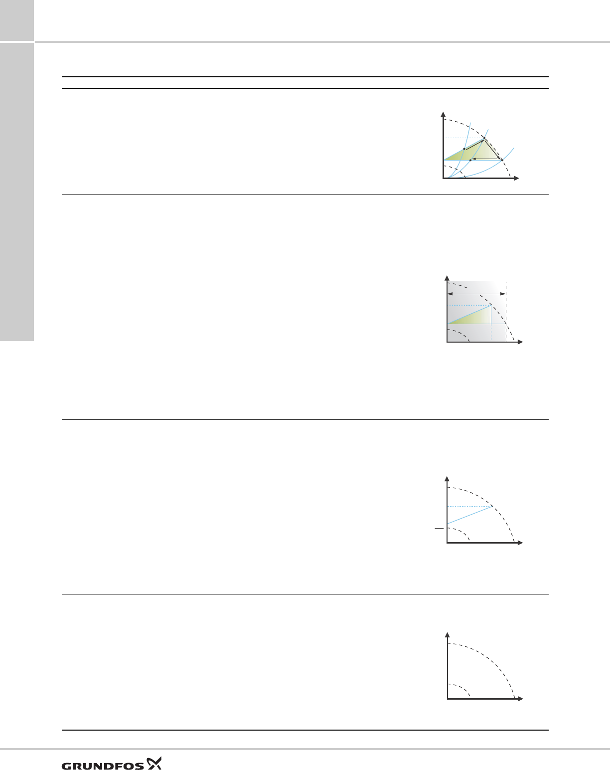
AUTOADAPT
Recommended for most heating systems.
During operation, the pump automatically makes the
necessary adjustment to the actual system
characteristic.
This setting ensures minimum energy consumption
and noise level from valves, which reduces operating
costs and increases comfort.
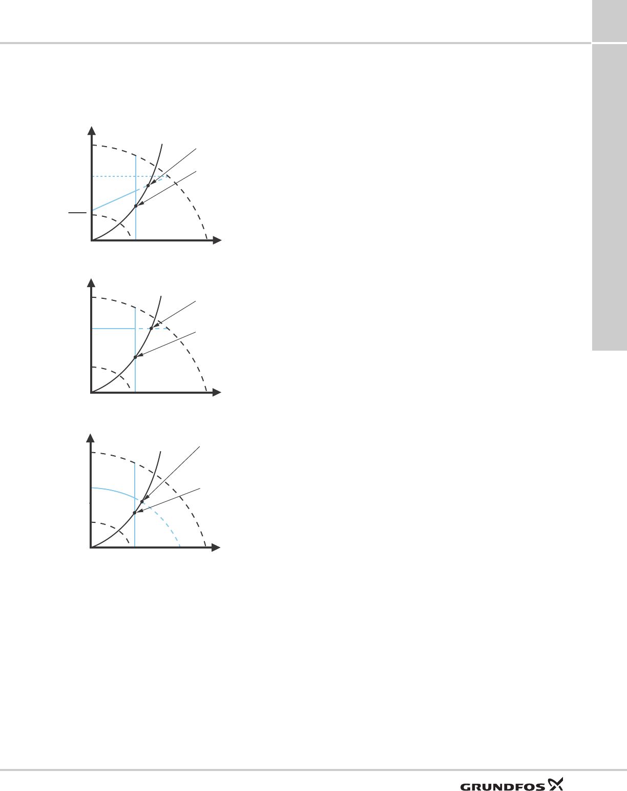
Fig. 25 AUTOADAPT control
Note: Manual setting of the setpoint is not possible.
When the AUTOADAPT control mode has been
enabled, the pump will start with the factory setting,
Hfac = Hset1, corresponding to approx. 55 % of its
maximum head, and then adjust its performance to A1.
See fig. 25.
When the pump registers a lower head on the max.
curve, A2, the AUTOADAPT function automatically
selects a correspondingly lower control curve, Hset2.
If the valves in the system close, the pump adjusts its
performance to A3.
The AUTOADAPT control mode is a form of proportional
pressure control where the control curves have a fixed
origin, Hauto_min.
The AUTOADAPT control mode has been developed
specifically for heating systems and is not
recommended for air-conditioning and cooling
systems.
TM05 2446 5111
H
Q
Max.
Min.
TM05 2452 1312
A1: Original duty point.
A2: Lower registered head on the max. curve.
A3: New duty point after AUTOADAPT control.
Hset1: Original setpoint setting.
Hset2: New setpoint after AUTOADAPT control.
Hfac: See page 32.
Hauto_min: A fixed value of 1.5 m.
H
Q
H
auto_min
H
fac
A
1
A
3
A
2
H
set1
H
set2
Functions
MAGNA3
8
28
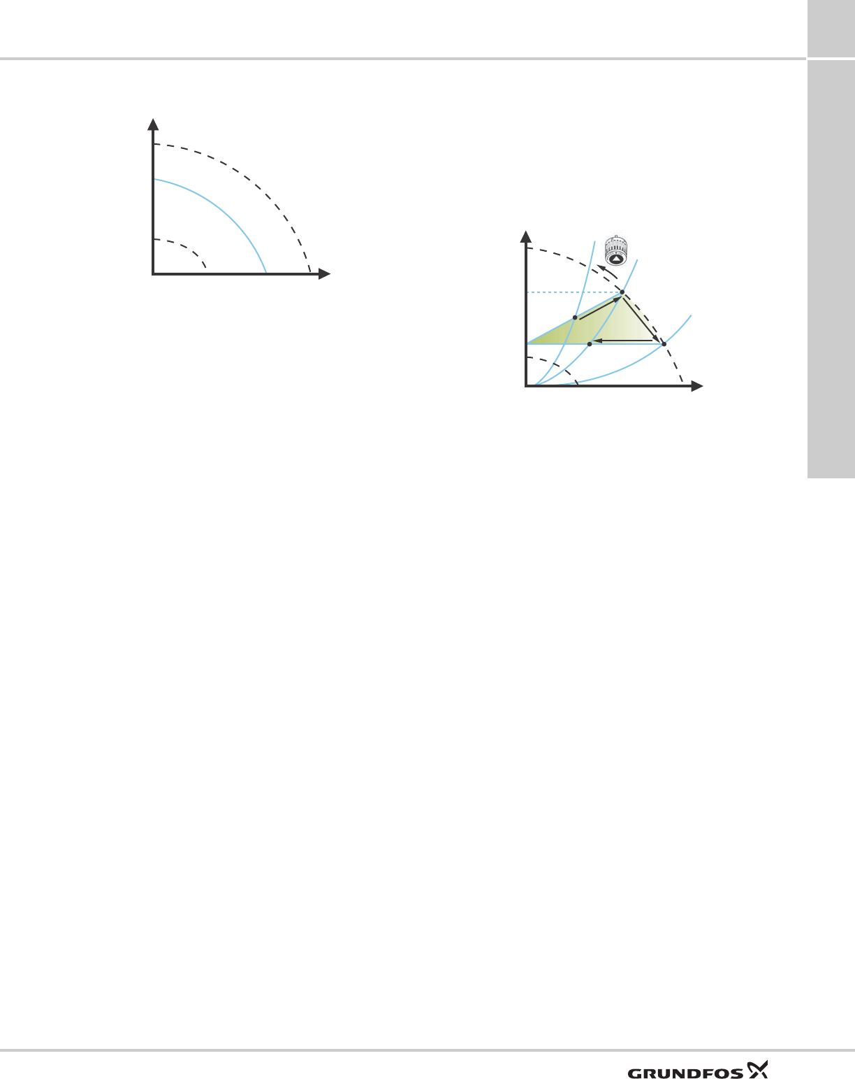
FLOWADAPT
The typical pump selection is based on required flow
and calculated pressure losses. The pump is typically
oversized by 30 to 40 % to ensure that it can overcome
the pressure losses in the system. Under these
conditions, the full benefit of AUTOADAPT cannot be
obtained.
To adjust the maximum flow of this "oversized" pump,
balancing valves are built into the circuit to increase
the resistance and thus reduce the flow. The
FLOWADAPT function reduces the need for a pump
throttling valve.
Note: This function cannot eliminate the need for
balancing valves in heating systems.
Fig. 26 Reduced need for a pump throttling valve
The FLOWADAPT control mode combines a control
mode and a function:
• The pump is running AUTOADAPT.
• The flow will never exceed a selected FLOWLIMIT
value, which reduces the need for a pump throttling
valve connected in series with the pump.
Fig. 27 FLOWADAPT control
When FLOWADAPT is selected, the pump will run
AUTOADAPT and ensure that the flow never exceeds
the entered FLOWLIMIT value.
The factory setting of the FLOWADAPT is the flow
where the AUTOADAPT factory setting meets the max.
curve. See fig. 27 and section Selection of control
mode, page 24.
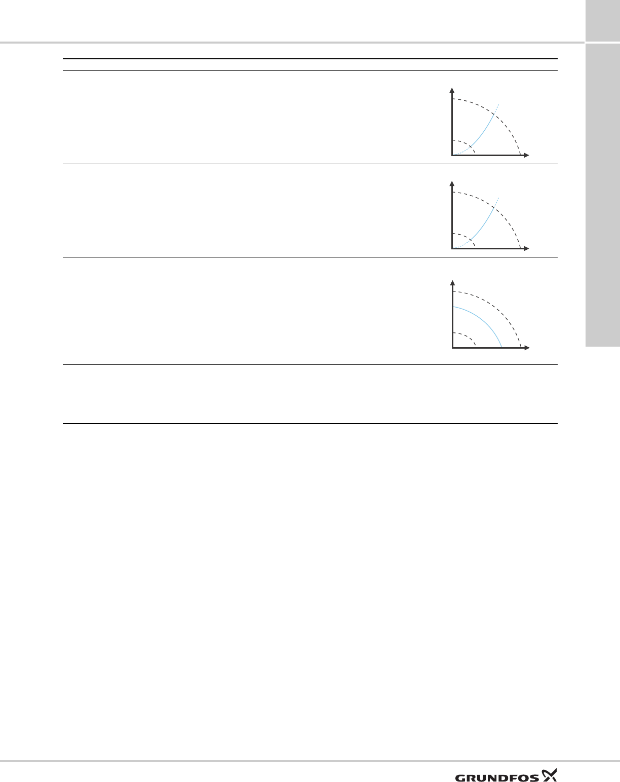
Proportional pressure
This control mode is used in systems with relatively
large pressure losses in the distribution pipes. The
head of the pump will increase proportionally to the
flow in the system to compensate for the large
pressure losses in the distribution pipes. The setpoint
can be set with an accuracy of 0.1 meter.
The head against a closed valve is half the setpoint
Hset.
Fig. 28 Proportional pressure control
Constant pressure
We recommend this control mode in systems with
relatively small pressure losses.
The pump head is kept constant, independent of the
flow in the system.
Fig. 29 Constant pressure control
TM05 2685 1212TM05 3334 1312
H
Q
Q
max
90 %
H
auto_min
H
fac
Q
fac
Setting range
TM05 2448 1212TM05 2449 0312
H
Q
Hset
Hset
2
H
Q
Functions
MAGNA3 8
29
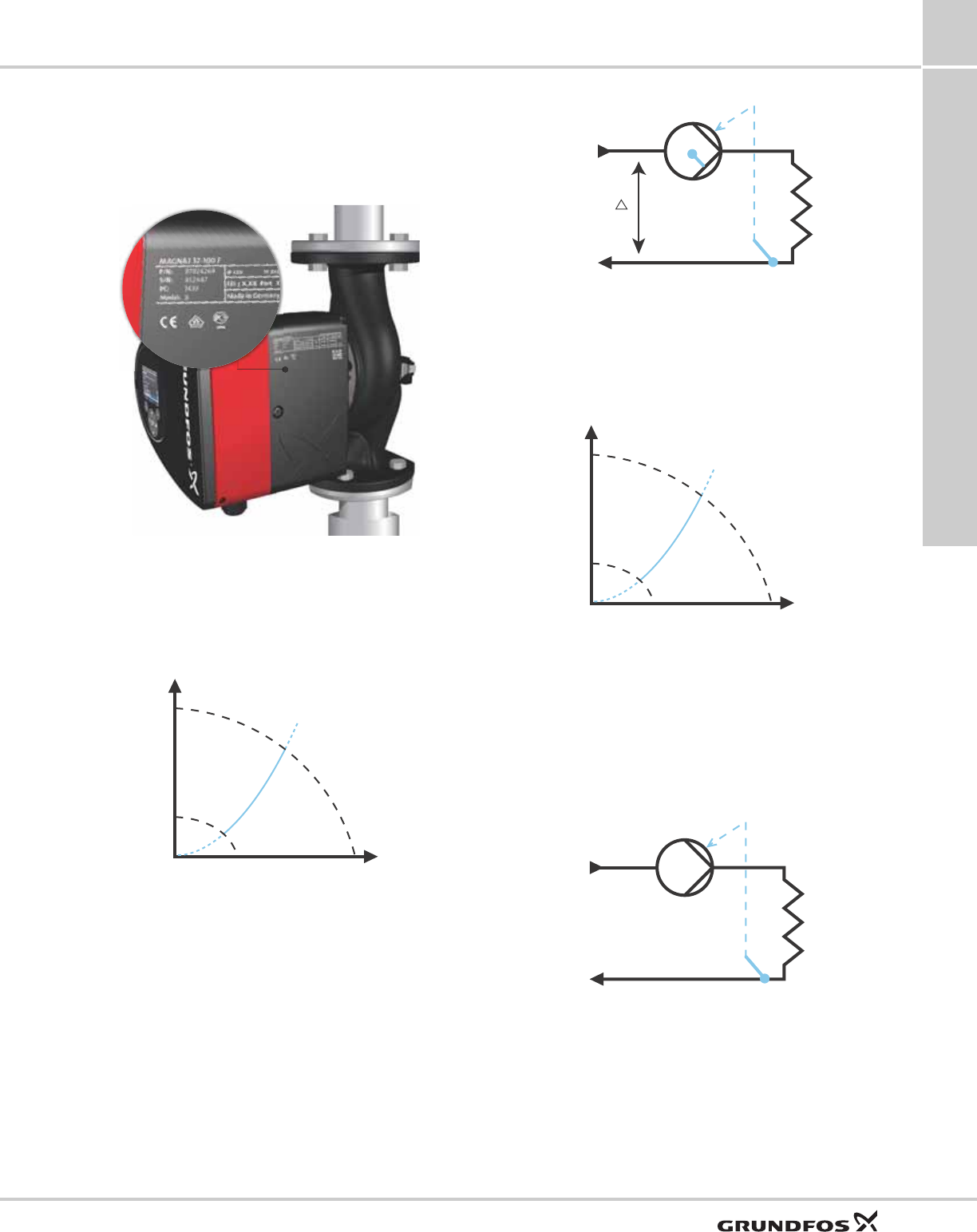
Differential temperature
The differential-temperature control mode is available
from model B which will be released in 2014. The
production code is stated on the nameplate. See fig.
30.
Fig. 30 Production code on nameplate
This control mode ensures a constant differential
temperature drop across heating and cooling systems.
In this control mode, the pump will maintain a constant
differential temperature between the pump and the
external sensor. See fig. 31 and fig. 32.
Fig. 31 Differential temperature
Temperature sensor
If the pump is installed in the flow pipe, the internal
temperature sensor can be used. An external
temperature sensor must be installed in the return pipe
of the system. The sensor must be installed as close
as possible to the consumer (radiator, heat exchanger,
etc.). See fig. 32.
Fig. 32 Differential temperature
Constant temperature
In heating systems with a fixed system characteristic,
for example domestic hot water systems, the control of
the pump according to a constant return-pipe
temperature is relevant.
Fig. 33 Constant temperature control
The inverse control for cooling application is available
from model B.
Temperature sensor
If the pump is installed in the flow pipe, an external
temperature sensor must be installed in the return pipe
of the system. See fig. 34. The sensor must be
installed as close as possible to the consumer
(radiator, heat exchanger, etc.).
Fig. 34 Pump with external sensor
TM05 8798 5113
TM05 2451 5111
H
Q
Δt
TM05 8235 2113TM05 2451 5111 TM05 2615 0312
tF
t
t
R
H
Q
tF
tR
Functions
MAGNA3
8
30
If the pump is installed in the return pipe of the system,
the internal temperature sensor can be used. In this
case, the pump must be installed as close as possible
to the consumer (radiator, heat exchanger, etc.).
Fig. 35 Pump with internal sensor
Constant curve
The pump can be set to operate according to a
constant curve, like an uncontrolled pump. See fig. 36.
The desired speed can be set in % of maximum speed
in the range from 25 to 100 %.
Fig. 36 Constant curve duty
Note: If the pump speed is set in the range between
minimum and maximum, the power and pressure are
limited when the pump is running on the max. curve.
This means that the maximum performance can be
achieved at a speed lower than 100 %. See fig. 37.
Fig. 37 Power and pressure limitations influencing the
max. curve
The pump can also be set to operate according to the
max. or min. curve, like an uncontrolled pump:
• The max. curve mode can be used in periods in
which a maximum flow is required. This operating
mode is for instance suitable for hot water priority.
• The min. curve mode can be used in periods in
which a minimum flow is required. This operating
mode is for instance suitable for manual night
setback if Automatic Night Setback is not desired.
These two operating modes can be selected via the
digital inputs.
Additional features for control
modes
The MAGNA3 offers additional features for the control
modes to meet specific demands.
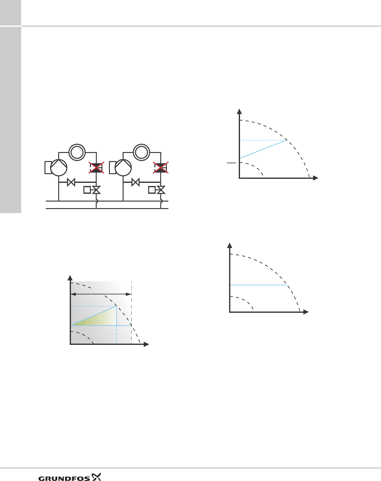
FLOWLIMIT
Fig. 38 FLOWLIMIT
The setting range for the FLOWLIMIT is 0 to 90 % of the
Qmax of the pump.
Note: Do not set the FLOWLIMIT lower than the
dimensioned duty point.
The FLOWLIMIT function offers the possibility of limiting
the maximum flow delivered by the pump.
The FLOWLIMIT function can be enabled when the
pump is in one of the following control modes:
• proportional pressure
• constant pressure
• constant temperature
• constant curve.
In the flow range between 0 and Qmax, the pump will
run according to the selected control mode.
TM05 2616 0312TM05 2446 5111TM05 4266 2212
tF
tR
H
Q
H
Q
Min.
30%
50%
70%
90%
Limited max. curve
Speed setting from 0 to 100 %
TM05 2445 1312
H
Q
Q
max
Q
limit
90 %
Setting range
Functions
MAGNA3 8
31
When Qmax is reached, the FLOWLIMIT function will
reduce the pump speed to ensure that the flow never
exceeds the FLOWLIMIT set, no matter if the system
requires a higher flow due to a reduced resistance in
the system. See fig. 39, 40 or 41.
Fig. 39 Proportional pressure control with FLOWLIMIT
Fig. 40 Constant pressure control with FLOWLIMIT
Fig. 41 Constant curve with FLOWLIMIT
Automatic Night Setback
Once Automatic Night Setback has been enabled, the
pump automatically changes between normal duty and
night setback (duty at low performance).
When Automatic Night Setback has been enabled, the
pump will run on the min. curve.
Changeover between normal duty and night setback
depends on the flow-pipe temperature.
The pump automatically changes over to night setback
when the built-in sensor registers a flow-pipe
temperature drop of more than 18 to 27 °F (10 to 15
°C) within approx. two hours. The temperature drop
must be at least 1.8 °F/min (0.1 °C/min).
Changeover to normal duty takes place without a time
lag when the temperature has increased by approx. 18
°F (10 °C).
Note: Automatic Night Setback cannot be enabled
when the pump is in constant curve mode.
TM05 2543 0412TM05 2544 0312TM05 2542 0412
H
Q
2
H
set
H
set
Normal proportional pressure
duty point
FLOWLIMIT duty point
H
Q
H
set
Normal constant pressure
duty point
FLOWLIMIT duty point
H
Q
Normal constant curve
duty point
FLOWLIMIT duty point

Functions
MAGNA3
8
32
Setting values for control modes
The setting values for FLOWADAPT and FLOWLIMIT are indicated as percent of Qmax, but the value has to be entered
in m3/h in the "Settings" menu.
The duty ranges for proportional pressure and constant pressure control appear from the individual data sheet.
Constant curve duty: 0 to 100 % speed.
* Stainless steel version available for single head unit only.
Pump type
AUTOADAPT
Hfac Qmax
FLOWADAPT / FLOWLIMIT
Qfac Qmin 25 % Qmax 90 %
[ft (m)] [gpm (m3/h)] [gpm (m3/h)] [gpm (m3/h)] [gpm (m3/h)]
MAGNA3 32-60 F (N) 11.5 (3.5) 48.5 (11.0) 26.0 (5.9) 12.4 (2.8) 43.6 (9.9)
MAGNA3 32-100 F (N) 18.1 (5.5) 57.3 (13.0) 29.5 (6.7) 14.6 (3.3) 51.6 (11.7)
MAGNA3 40-80 F (N) 14.8 (4.5) 94.7 (21.5) 57.2 (13) 23.8 (5.4) 85.4 (19.4)
MAGNA3 40-120 F (N) 21.3 (6.5) 112.2 (25.5) 70.4 (16) 28.2 (6.4) 101.2 (23)
MAGNA3 40-180 F (N) 31.2 (9.5) 125.4 (28.5) 66.0 (15) 31.2 (7.1) 113.1 (25.7)
MAGNA3 50-80 F (N) 14.8 (4.5) 129.8 (29.5) 74.8 (17) 32.6 (7.4) 117.0 (26.6)
MAGNA3 50-150 F (N) 26.2 (8.0) 165.0 (37.5) 88.0 (20) 41.4 (9.4) 148.7 (33.8)
MAGNA3 65-120 F (N) 21.3 (6.5) 209.0 (47.5) 132.0 (30) 52.4 (11.9) 188.3 (42.8)
MAGNA3 (D) 65-150 F (N)* 26.2 (8.0) 248.6 (56.5) 176.0 (40) 62.0 (14.1) 224.0 (50.9)
MAGNA3 (D) 80-100 F (N)* 18.0 (5.5) 297.0 (67.5) 206.8 (47) 74.4 (16.9) 267.5 (60.8)
MAGNA3 (D) 100-120 F (N)* 21.3 (6.5) 345.4 (78.5) 250.8 (57) 86.2 (19.6) 311.1 (70.7)
Functions
MAGNA3 8
33
Additional operating modes for
multi-pump setup
Multi-pump function
The multi-pump function enables the control of
single-head pumps connected in parallel and
twin-head pumps without the use of external
controllers. The pumps in a multi-pump system
communicate with each other via the wireless GENIair
connection.
A multi-pump system is set up via a selected pump, i.e.
the master pump (first selected pump). All Grundfos
pumps with a wireless GENIair connection can be
connected to the multi-pump system.
The multi-pump functions are described in the
following sections.
Alternating operation
Only one pump is operating at a time. The change from
one pump to the other depends on time or energy. If a
pump fails, the other pump will take over automatically.
Pump system:
• Twin-head pump.
• Two single-head pumps connected in parallel. The
pumps must be of equal size and type. Each pump
requires a non-return valve in series with the pump.
Back-up operation
One pump is operating continuously. The back-up
pump is operated at intervals to prevent seizing up. If
the duty pump stops due to a fault, the back-up pump
will start automatically.
Pump system:
• Twin-head pump.
• Two single-head pumps connected in parallel. The
pumps must be of equal size and type. Each pump
requires a non-return valve in series with the pump.
Cascade operation
Cascade operation ensures that the pump
performance is automatically adapted to the
consumption by switching pumps on or off. The system
thus runs as energy-efficiently as possible with a
constant pressure and a limited number of pumps.
The back-up of a twin-head pump will start at 90 % and
stop at 30 % performance when operating in constant
pressure mode.
It can be advantageous to choose a twin-head pump,
as the back-up pump will start for a short period in
peak-load situations. If an oversized single-head pump
is chosen, it may run outside its best efficiency range
most of the time.
All pumps in operation will run at equal speed. Pump
changeover is automatic and depends on speed,
operating hours and fault.
Pump system:
• Twin-head pump.
• Two single-head pumps connected in parallel. The
pumps must be of equal size and type. Each pump
requires a non-return valve in series with the pump.
• The control mode must be set to "Const. press." or
"Constant curve".
Readings and settings on the pump
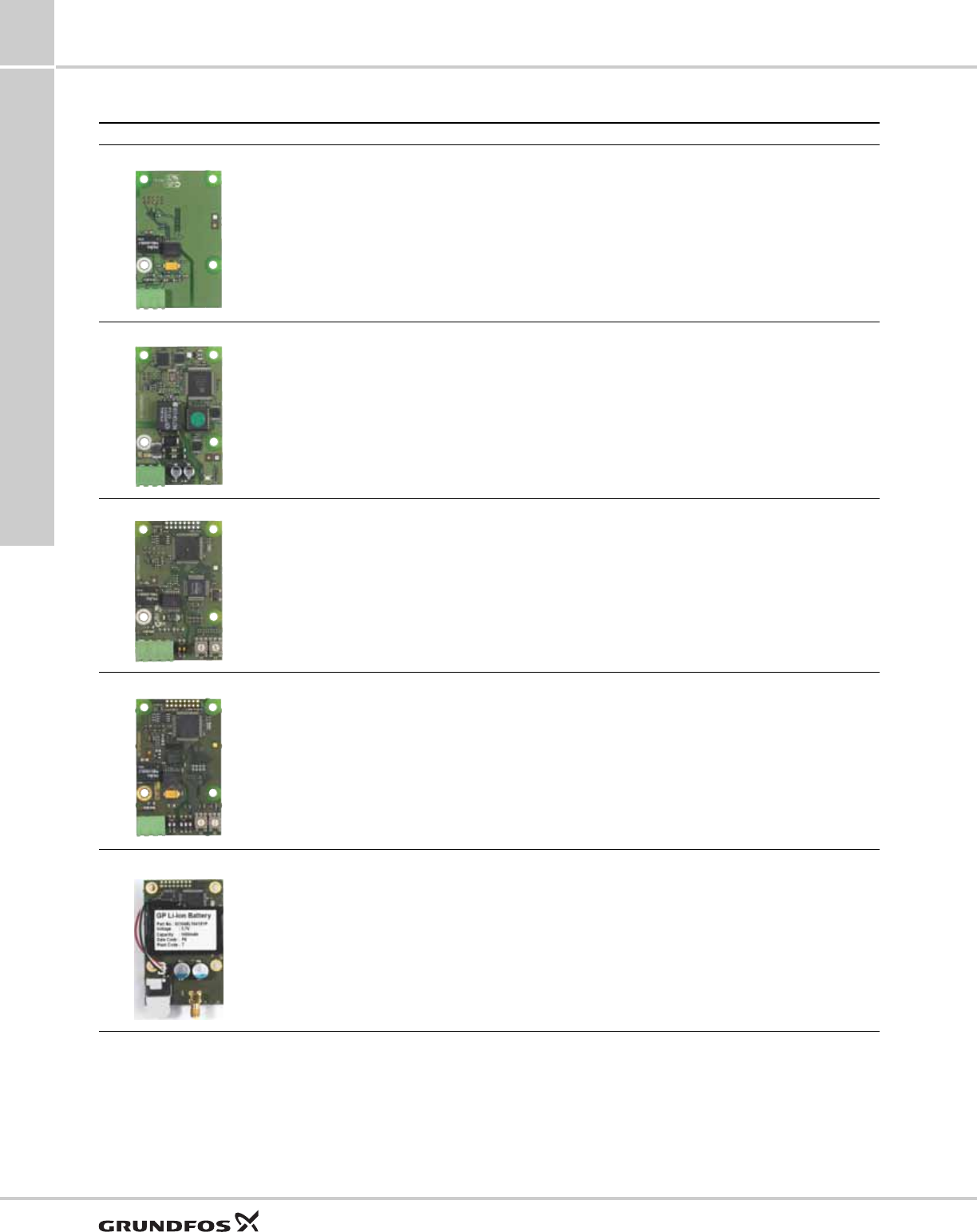
Control panel and display
The MAGNA3 pump features a 4" TFT display with
intuitive and user-friendly interface. The control panel
has self-explanatory push-buttons made of high-quality
silicone for precise navigation in the menu structure.
The control panel is designed to give the user quick
and easy access to pump and performance data on
site.
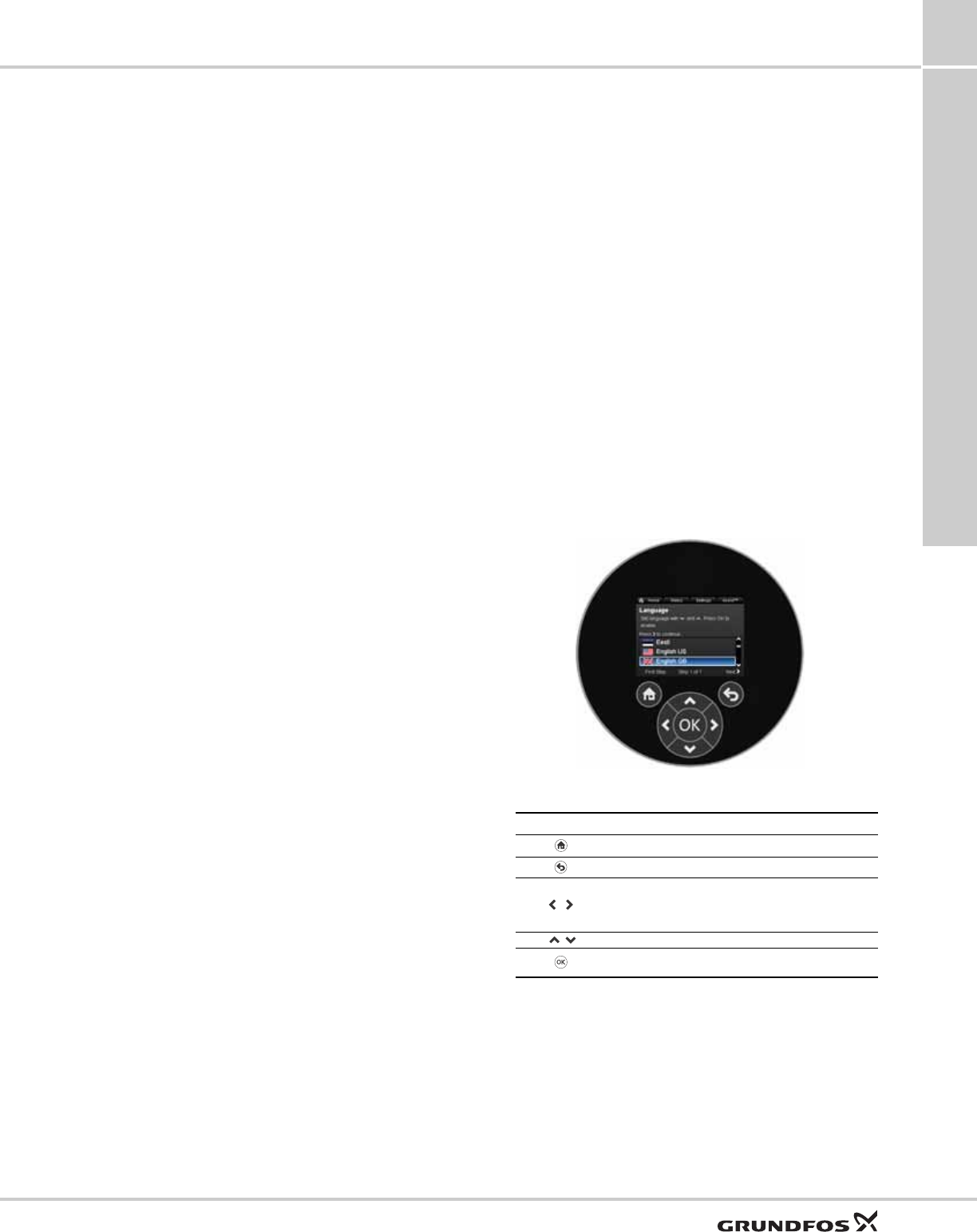
When the pump is started up for the first time, the user
is presented with a start-up guide enabling easy
setting of the pump. Additionally, the "Assist" menu
can guide the user through the various settings of the
pump.
Fig. 42 Control panel
TM05 3820 1612
Button Function
Goes to the "Home" menu.
Returns to the previous action.
Navigates between main menus, displays and
digits.
When the menu is changed, the display will always
show the top display of the new menu.
Navigates between submenus.
Saves changed values, resets alarms and expands
the value field.
Functions
MAGNA3
8
34
Factory setting
The pumps have been factory-set to AUTOADAPT
without Automatic Night Setback.
Start-up guide
The start-up guide is used for the general settings of
the pump. The start-up guide is started the first time
the pump is connected to the power supply.
Note: If there has been no user action after pump
start-up, the pump will automatically leave the start-up
guide after 15 minutes with the language set to
English.
The start-up guide can be run again in the "Settings"
menu. If the start-up guide is run again, all previous
settings will be lost.
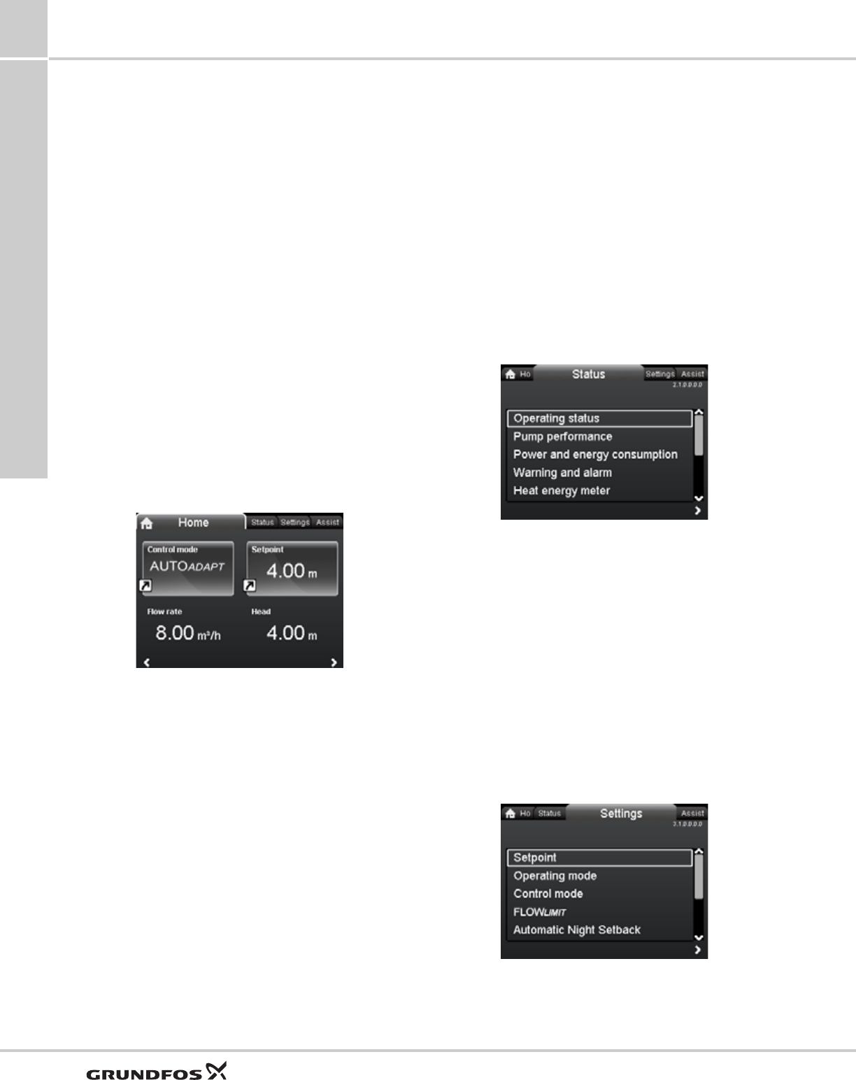
"Home" menu
This menu gives an overview of up to four user-defined
parameters or a graphical illustration of a Q/H
performance curve.
This menu offers the following (factory setting):
• Shortcut to Control mode settings
• Shortcut to Setpoint settings
•Flow rate
•Head.
Fig. 43 "Home" menu
"Status" menu
This menu shows the status of the pump and system
as well as warnings and alarms.
Note: No settings can be made in this menu.
This menu offers the following:
•Operating status
•Pump performance
•Power and energy consumption
•Warning and alarm
•Heat energy meter
•Work log
•Fitted modules
•Date and time
•Pump identification
•Multi-pump system.
Fig. 44 "Status" menu
"Settings" menu
This menu gives access to all setting parameters. A
detailed setting of the pump can be made in this menu.
This menu offers the following setting options:
•Setpoint
•Operating mode
•Control mode
•FLOW
LIMIT
•Automatic Night Setback
•Relay outputs
•Setpoint influence
•Bus communication
•General settings.
Fig. 45 "Settings" menu
Home
StatusSettings
Functions
MAGNA3 8
35
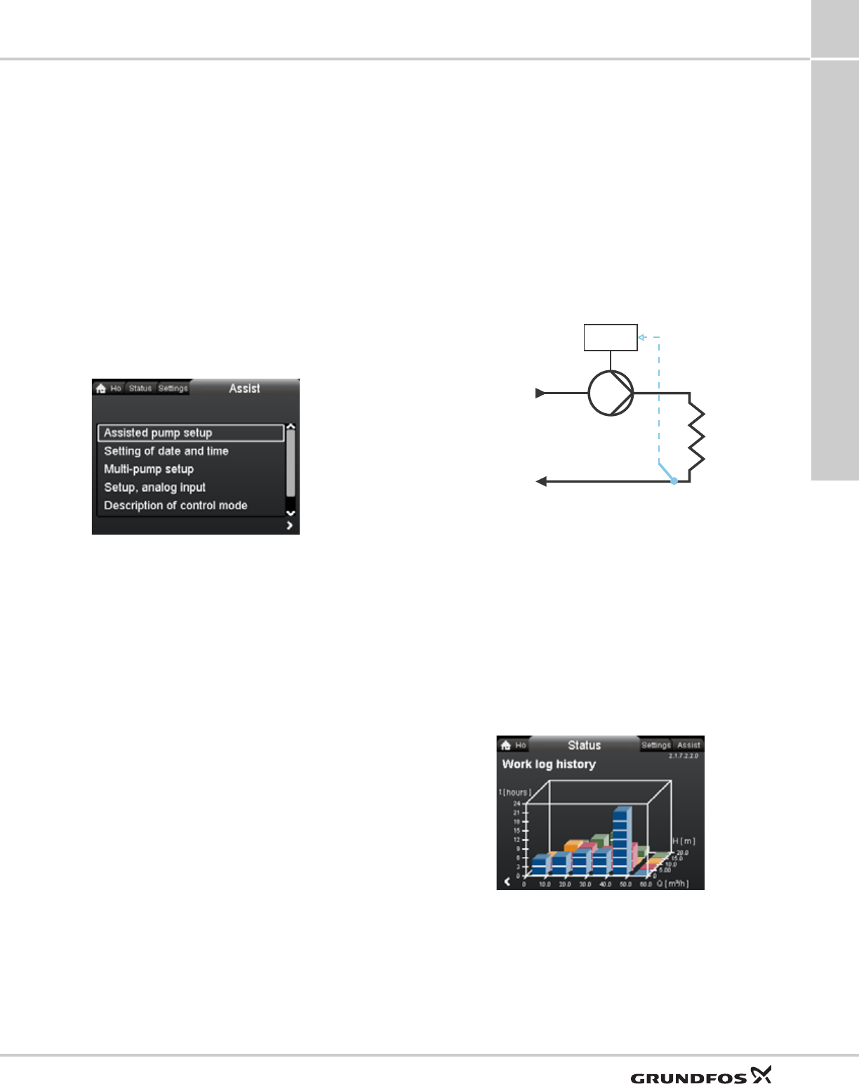
"Assist" menu
The "Assist" menu guides the user through the setting
of the pump. In each submenu, the user is presented
with a guide that assists throughout the setting.
This menu offers the following:
• Step-by-step instructions in how to set up the pump.
• A short description of the six control modes and
recommended applications.
• Assistance in fault correction.
Submenus:
•Assisted pump setup
•Setting of date and time
•Multi-pump setup
•Setup, analog input
•Description of control mode
•Assisted fault advice.
Fig. 46 "Assist" menu
Operating status
"Operating status" shows the current operating mode
and the selected control mode, if any.
Pump performance
"Pump performance" offers the following:
• Q/H graph showing current duty point, flow, head,
power and liquid temperature.
• "Resulting setpoint" shows the setpoint set on the
pump, the external influence and the resulting
setpoint.
• Liquid temperature.
• Speed.
• Operating hours.
Warning and alarm
"Warning and alarm" offers the following:
• Actual warning or alarm, if any.
• Information about when the warning/alarm occurred
and disappeared and about corrective actions.
• Warning and alarm logs.
Heat energy meter
"Heat energy meter" is a monitoring function which
makes it possible to track the heat energy distribution
and consumption within a system. This prevents
excessive energy costs caused by system imbalances.
The internal sensor has an accuracy of ± 1 % in the
general working area. In the "critical" working areas,
the measurement can vary by 10 %. This is one of the
reasons why the heat energy value cannot be used for
billing purposes. However, the value is perfect for
simple optimisation purposes.
The pump requires a temperature sensor in the flow
pipe or return pipe. This temperature sensor is not
supplied with the pump.
Fig. 47 MAGNA3 with built-in heat energy meter
Note: MAGNA3 incorporates a calculator for flow and
flow-pipe temperature.
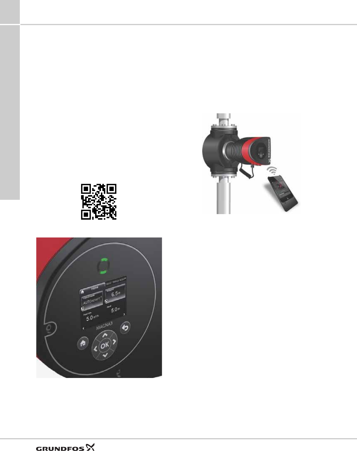
Work log history
"Work log history" offers the following:
• Every duty point and the operating conditions are
tracked and stored in the pump.
• The 3D work log and duty curve (over time) provide
instant overviews of historical pump performance
and operating conditions.
• The perfect tool for pump optimisation, replacement
and fault finding.
Fig. 48 Example of "Work log history"
Assist
TM05 5367 3612
Work log history
t
kWh
F
t
R
Functions
MAGNA3
8
36
Input for external sensor
An external differential pressure sensor can be used to
control the flow in the system to obtain the externally
set pressure, which results in following benefits:
• Minimises operating costs.
• Prevents valve noise.
• Ensures comfort (enough pressure).
Grundfos Eye
The Grundfos Eye at the top of the control panel is a
pump status indicator light providing information about
the pump operating status.
The indicator light will flash in different sequences and
provide information about the following:
• power on/off
• pump warnings
• pump alarms
• remote control.
The function of the Grundfos Eye is described in detail
in the installation and operating instructions.
Fig. 49 Grundfos Eye
Communication
The MAGNA3 enables communication via the
following:
• wireless Grundfos GO Remote
• fieldbus communication via CIM modules
• digital inputs
• relay outputs
• analog input.
Grundfos GO Remote
Fig. 50 Grundfos GO Remote
The MAGNA3 is designed for wireless communication
with the Grundfos GO Remote.
For more details, see section Grundfos GO Remote,
page 58.
The Grundfos GO Remote offers additional
possibilities of setting and status displays for the
pump.
The Grundfos GO Remote can be used for the
following functions:
• Reading of operating data.
• Reading of warning and alarm indications.
• Setting of control mode.
• Setting of setpoint.
• Selection of external setpoint signal.
• Allocation of pump number making it possible to
distinguish between pumps that are connected via
Grundfos GENIbus.
• Selection of function for digital input.
• Generation of reports (PDF).
• Assist function.
• Multi-pump setup.
• Displaying relevant documentation.
http://GRUNDFOS.COM/MANUAL-MAGNA3
TM05 3810 1612
TM05 3825 1712

Functions
MAGNA3 8
37
Wireless GENIair
The pump is designed for multi-pump connection via
the wireless GENIair connection.
The built-in wireless GENIair module enables
communication between pumps and with the Grundfos
GO Remote without the use of add-on modules.
• Multi-pump function.
See section Multi-pump function.
• Grundfos GO Remote.
See section Grundfos GO Remote.
CIM modules
Fig. 51 Grundfos CIM modules
A CIM module is an add-on Communication Interface
Module. The CIM module enables data transmission
between the pump and an external system, for
example a BMS (Building Management System) or
SCADA system.
The CIM module communicates via fieldbus protocols.
See section Available CIM modules, page 38.
Connection to network
The pump can be connected to a LON network via the
wireless GENIair connection or by fitting a CIM
module. Other types of network connections are also
possible. Contact Grundfos for further information on
how to connect to your network.
Grundfos Remote Management
Grundfos Remote Management is an easy-to-install,
low-cost solution for wireless monitoring and
management of Grundfos products. It is based on a
centrally hosted database and a web server with
wireless data collection via GSM/GPRS modem. The
system only requires an internet connection, a web
browser, a GRM modem and an antenna as well as a
contract with Grundfos allowing you to monitor and
manage Grundfos pump systems.
You have wireless access to your account anywhere,
anytime when you have an internet connection, for
example via a smartphone, tablet PC, laptop or
computer. Warnings and alarms can be sent by email
or SMS to your mobile phone or computer.
For CIM communication interface module and GSM
antennas, see section Grundfos Remote Management,
page 57.
TM05 3811 1612
Functions
MAGNA3
8
38
Available CIM modules
Module Fieldbus protocol Description Functions
CIM 050
TM05 3812 1612
GENIbus
The CIM 050 is a Grundfos communication
interface module used for communication
with a GENIbus network.
The CIM 050 has terminals for the GENIbus
connection.
CIM 100
TM05 3813 1612
LonWorks
The CIM 100 is a Grundfos communication
interface module used for communication
with a LonWorks network.
The CIM 100 has terminals for the LonWorks
connection.
Two LEDs are used to indicate the actual status
of the CIM 100 communication.
One LED is used for indication of correct
connection to the pump, and the other is used to
indicate LonWorks communication status.
CIM 150
TM05 3814 1612
PROFIBUS DP
The CIM 150 is a Grundfos communication
interface module used for communication
with a PROFIBUS network.
The CIM 150 has terminals for the PROFIBUS
DP connection.
DIP switches are used to set line termination.
Two hexadecimal rotary switches are used to set
the PROFIBUS DP address.
Two LEDs are used to indicate the actual status
of the CIM 150 communication.
One LED is used for indication of correct
connection to the pump, and the other is used to
indicate PROFIBUS communication status.
CIM 200
TM05 3815 1612
Modbus RTU
The CIM 200 is a Grundfos communication
interface module used for communication
with a Modbus RTU network.
The CIM 200 has terminals for the Modbus
connection.
DIP switches are used to select parity and stop
bits, to select transmission speed and to set line
termination.
Two hexadecimal rotary switches are used to set
the Modbus address.
Two LEDs are used to indicate the actual status
of the CIM 200 communication.
One LED is used for indication of correct
connection to the pump, and the other is used to
indicate Modbus communication status.
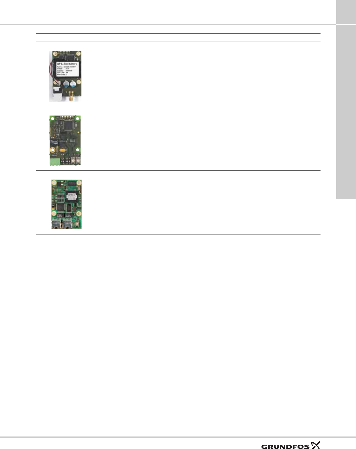
CIM 250
TM05 4432 2212
GSM/GPRS
The CIM 250 is a Grundfos communication
interface module used for GSM/GPRS
communication.
The CIM 250 is used to communicate via a
GSM network.
The CIM 250 has a SIM-card slot and an SMA
connection to the GSM antenna.
The CIM 250 also has an internal backup battery.
Two LEDs are used to indicate the actual status
of the CIM 250 communication. One LED is used
for indication of correct connection to the pump,
and the other is used to indicate GSM/GPRS
communication status.
Note: The SIM card is not supplied with the CIM
250. The SIM card from the service provider must
support data/fax service to use call service from
PC Tool or SCADA. The SIM card from the
service provider must support GPRS service to
use Ethernet service from PC Tool or SCADA.
Functions
MAGNA3 8
39
For product numbers, see section CIM modules, page 57.
CIM 270
TM05 4432 2212
Grundfos Remote
Management
The CIM 270 is a Grundfos GSM/GPRS
modem used for communication with a
Grundfos Remote Management system.
It requires a GSM antenna, a SIM card and
a contract with Grundfos.
With the CIM 270 you have wireless access to
your account anywhere, anytime when you have
an internet connection, for example via a
smartphone, tablet PC, laptop or computer.
Warnings and alarms can be sent by e-mail or
SMS to your mobile phone or computer. You will
get a complete status overview of the entire GRM
system. It allows you to plan maintenance and
service based on actual operating data.
CIM 300
TM05 3815 1612
BACnet MS/TP
The CIM 300 is a Grundfos communication
interface module used for communication
with a BACnet MS/TP network.
The CIM 300 has terminals for the BACnet
MS/TP connection.
DIP switches are used to set transmission speed
and line termination and to select the custom
Device Object Instance Number.
Two hexadecimal rotary switches are used to set
the BACnet address.
Two LEDs are used to indicate the actual status
of the CIM 300 communication.
One LED is used for indication of correct
connection to the pump, and the other is used to
indicate BACnet communication status.
CIM 500
TM05 8825 2713
Ethernet
The CIM 500 is a Grundfos communication
interface module used for data
transmission between an industrial
Ethernet network and a Grundfos product.
The CIM 500 supports various industrial Ethernet
protocols. The CIM 500 is configured via the
built-in web server, using a standard web browser
on a PC.
See the specific functional profile on the
DVD-ROM supplied with the Grundfos CIM
module.
Module Fieldbus protocol Description Functions
Guide to performance curves
MAGNA3
9
40
9. Guide to performance curves
Curve conditions
The guidelines below apply to the performance curves
on pages 42 to 55:
• Test liquid: airless water.
• The curves apply to a density of ρ = 61.38 lb/ft3
(983.2 kg/m3) and a liquid temperature of 140 °F
(+60 °C).
• All curves show average values and should not be
used as guarantee curves. If a specific minimum
performance is required, individual measurements
must be made.
• The curves apply to a kinematic viscosity of =
0.474 mm2/s (0.474 cSt).
• Reference supply voltage: 1 x 230 V, 50 Hz.
• EEI obtained according to EN 16297.
Note: Within the MAGNA3 performance range, the
constant pressure and proportional pressure curves
can be set in steps of 0.1 m head on the control panel
or with the Grundfos GO Remote.
Symbols used on the following pages
Fig. 52 Energy efficiency index (EEI)
The MAGNA3 is energy-optimized and complies with
the EuP Directive (Commission Regulation (EC) No
641/2009) which will be effective as from 1 January
2013.
For MAGNA3 pumps, the average energy efficiency
index (EEI) is 0.18 with values down to 0.17,
categorized as best in class.
Fig. 53 Old energy label
From 1 January 2013, the old A to G energy label will
be replaced by the new energy efficiency index (EEI).
Only the best of today’s A-labelled circulator pumps
will meet the new requirements.
The MAGNA3 with its AUTOADAPT function is the
preferred choice for large heating systems and a true
efficiency frontrunner.
Figure 54 shows the energy consumption index for a
typical circulator pump compared to the various EEI
limits.
Fig. 54 Energy consumption index
With an energy efficiency index (EEI) well below the
EuP benchmark level. With AUTOADAPT the savings
can be as much as 85 %, compared to a typical
circulator pump and thus a remarkably fast return on
investment. This means, of course, that the MAGNA3
more than meets the standards of the EuP legislation.
TM05 2682 0412
BEST
in class
BEST
in class
TM05 3936 1712TM05 3935 1712
Index
10
0
20
30
40
50
80
60
90
70
100
Typical
circulator
pump
EuP
2013
EuP
2015
EuP
benchmark
level
MAGNA3
labelled
labelled
EEI = 0.27
EEI = 0.23
EEI = 0.20
EEI = 0.17
Typical
circulator
pump
EuP
2013
EuP
2015
EuP
benchmark
level
MAGNA3
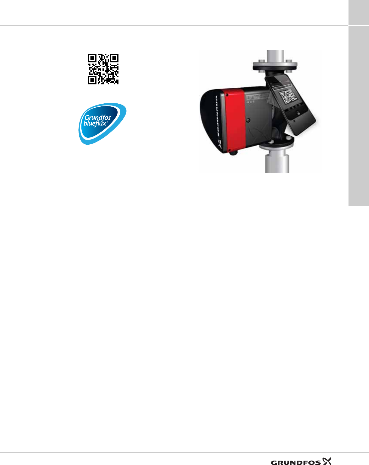
Guide to performance curves
MAGNA3 9
41
For more information about the new energy directive,
please visit:
Fig. 55 Grundfos blueflux®
The Grundfos blueflux® label is your guarantee that
the MAGNA3 incorporates the most energy-efficient
motor currently available. Grundfos blueflux® motors
are designed to cut the power consumption by up to 60
% and thus reduce CO2 emissions and operating
costs.
QR code on pump nameplate
Fig. 56 QR code on pump nameplate
With the Grundfos GO Remote or a smartphone, it is
possible to get the following information about the
MAGNA3:
• product photo
• pump performance curves
• dimensional sketches
• wiring diagram
• quotation text
• technical data
• service parts list
• PDF files, such as data booklet and installation and
operating instructions.
TM05 2683 0412
http://energy.Grundfos.com
TM05 2683 0412
TM05 3826 1712
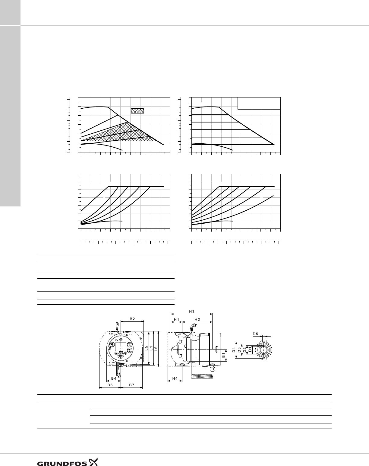
Performance curves and technical data
10
42
MAGNA3Performance curves and technical data
10. Performance curves and technical data
MAGNA3 32-60 F (N) 1 x 115-230 V, 50/60 Hz
For product numbers, see page 7.
TM06 0657 0714
0 5 10 15 20 25 30 Q [US GPM]
0
4
8
12
16
20
24
[ft]
H
0
2
4
6
8
10
[psi]
p
MAX
MIN
AUTOADAPT
0 5 10 15 20 25 30 Q [US GPM]
0
20
40
60
80
100
120
140
[W]
P1
0 2 4 6 8 Q [m³/h]
MAX
MIN
2m
5m
0 5 10 15 20 25 30 Q [US GPM]
0
4
8
12
16
20
24
[ft]
H
0
2
4
6
8
10
[psi]
p
MAGNA3 32-60 F (N)
MAX
MIN
0 5 10 15 20 25 30 Q [US GPM]
0
20
40
60
80
100
120
140
[W]
P1
0 2 4 6 8 Q [m³/h]
MAX
MIN
1m
5m
Proportional pressure Constant pressure
Speed I1/1 [A] 115 V P1 [W] 115 V I1/1 [A] 230 V P1 [W] 230 V
Min. 0.28 8.5 0.09 9
Max. 1.01 107.7 0.91 110
The pump incorporates overload protection.
Net weights [lbs (kg)] Gross weights [lbs (kg)] Ship. vol. [ft3 (m3)]
12.3 (5.5) 14.4 (6.5) 0.46 (0.014)
System pressure: Max. 175 psi (12 bar)
Liquid temperature: 14 to 230 °F (-10 °C to +110 °C)
Also available with: Stainless-steel pump housing, type N
Specific EEI: 0.18
TM06 0734 0814
Pump type Dimensions [in (mm)]
MAGNA3 32-60 F (N)
L1 L5 L6 B1 B2 B4 B6 B7 D1
6.50 (165) 6.23 (158) 6.62 (168) 2.29 (58) 4.38 (111) 2.72 (69) 4.18 (106) 4.18 (106) 1.26 (32)
D2 D3 D4 D5 H1 H2 H3 H4
1.82 (46) 2.29 (58) 3.15 (80) 0.46 (11.5) 2.13 (54) 7.37 (187) 2.49 (241) 2.76 (70)
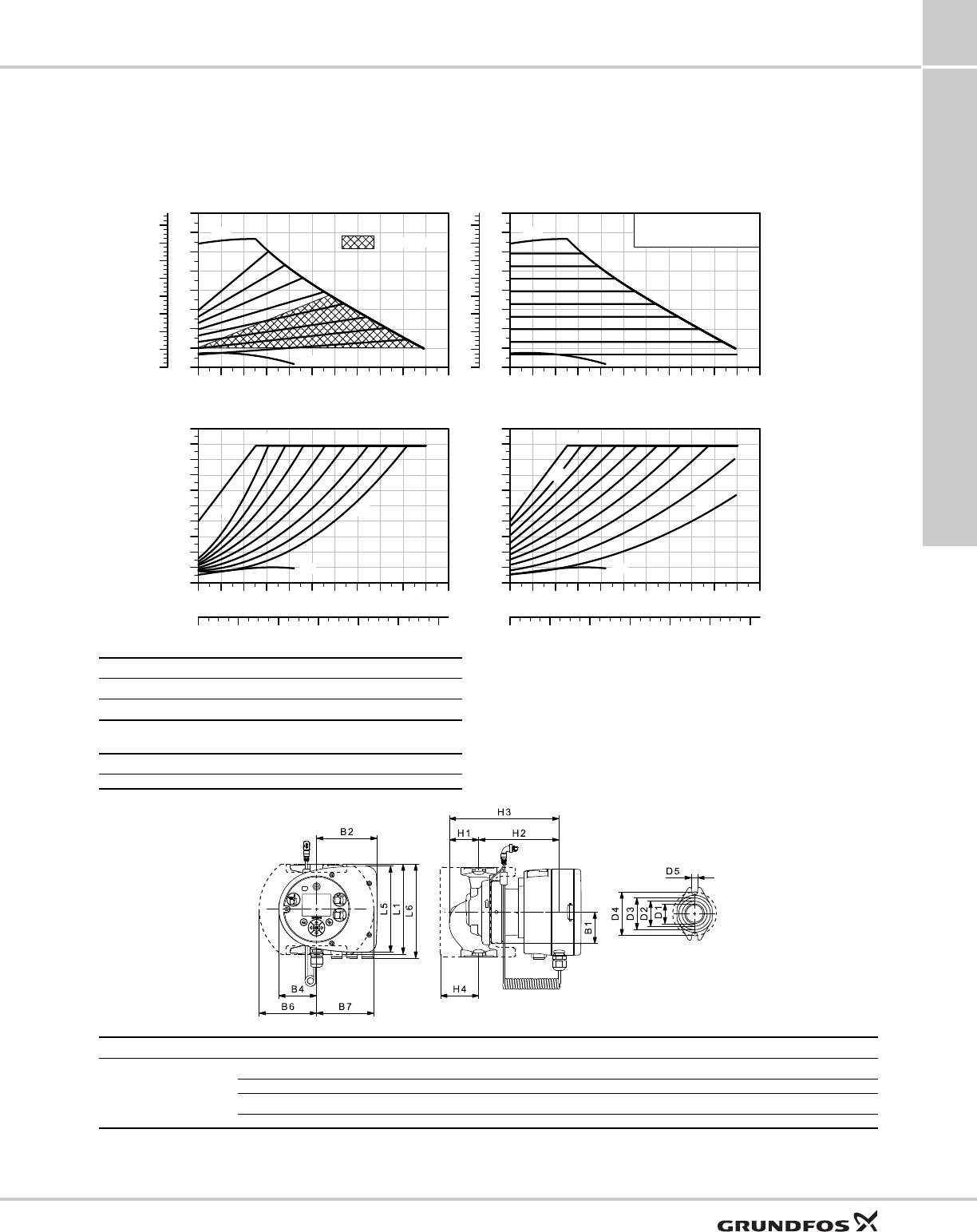
Performance curves and technical data
10
43
MAGNA3 Performance curves and technical data
MAGNA3 32-100 F (N) 1 x 115-230 V, 50/60 Hz
For product numbers, see page 7.
TM06 0659 0714
0 5 10 15 20 25 30 35 40 Q [US GPM]
0
5
10
15
20
25
30
35
40
[ft]
H
0
2
4
6
8
10
12
14
16
[psi]
p
MAX
MIN
AUTOADAPT
0 5 10 15 20 25 30 35 40 Q [US GPM]
0
20
40
60
80
100
120
140
160
180
200
[W]
P1
0 2 4 6 8 10 Q [m³/h]
MAX
MIN
2 m
9m
0 5 10 15 20 25 30 35 40 Q [US GPM]
0
5
10
15
20
25
30
35
40
[ft]
H
0
2
4
6
8
10
12
14
16
[psi]
p
MAGNA3 32-100 F (N)
MAX
MIN
0 5 10 15 20 25 30 35 40 Q [US GPM]
0
20
40
60
80
100
120
140
160
180
200
[W]
P1
0 2 4 6 8 10 Q [m³/h]
MAX
MIN
1m
9m
Proportional pressure Constant pressure
Speed I1/1 [A] 115 V P1 [W] 115 V I1/1 [A] 230 V P1 [W] 230 V
Min. 0.29 9.7 0.09 9
Max. 1.61 178.3 1.47 180
The pump incorporates overload protection.
Net weights [lbs (kg)] Gross weights [lbs (kg)] Ship. vol. [ft3 (m3)]
12.3 (5.5) 14.4 (6.5) 0.46 (0.014)
System pressure: Max. 175 psi (12 bar)
Liquid temperature: 14 to 230 °F (-10 °C to +110 °C)
Also available with: Stainless-steel pump housing, type N
Specific EEI: 0.18
TM06 0734 0814
Pump type Dimensions [in (mm)]
MAGNA3 32-100 F (N)
L1 L5 L6 B1 B2 B4 B6 B7 D1
6.50 (165) 6.23 (158) 6.62 (168) 2.29 (58) 4.38 (111) 2.72 (69) 4.18 (106) 4.18 (106) 1.26 (32)
D2 D3 D4 D5 H1 H2 H3 H4
1.82 (46) 2.29 (58) 3.15 (80) 0.46 (11.5) 2.13 (54) 7.37 (187) 2.49 (241) 2.76 (70)
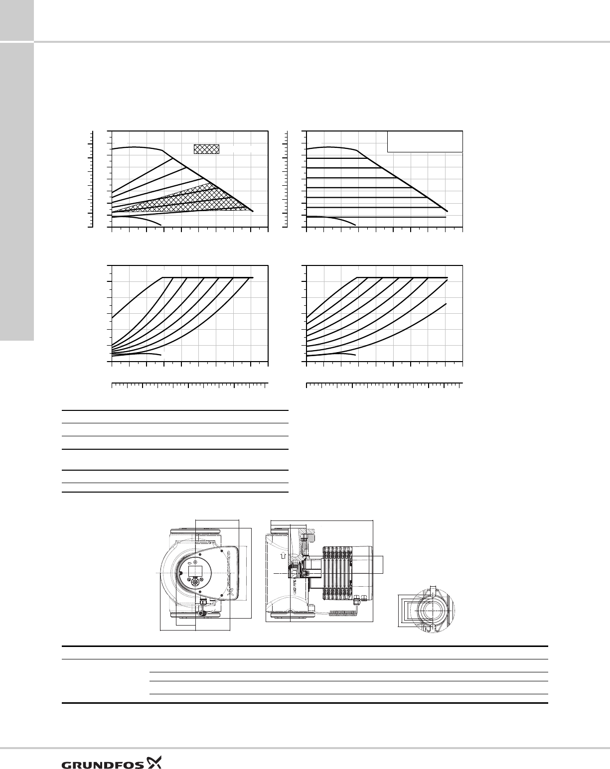
Performance curves and technical data
10
44
MAGNA3Performance curves and technical data
MAGNA3 40-80 F (N) 1 x 115 & 208-230 V, 50/60 Hz
For product numbers, see page 7.
TM05 8103 1214
0 10 20 30 40 50 60 Q [US GPM]
0
4
8
12
16
20
24
28
32
[ft]
H
0
2
4
6
8
10
12
[psi]
p
MAX
MIN
AUTOADAPT
0 10 20 30 40 50 60 Q [US GPM]
0
50
100
150
200
250
300
[W]
P1
0 2 4 6 8 10 12 14 16 Q [m³/h]
MAX
MIN
0 10 20 30 40 50 60 Q [US GPM]
0
4
8
12
16
20
24
28
32
[ft]
H
0
2
4
6
8
10
12
[psi]
p
MAGNA3 40-80 F (N)
MAX
MIN
0 10 20 30 40 50 60 Q [US GPM]
0
50
100
150
200
250
300
[W]
P1
0 2 4 6 8 10 12 14 16 Q [m³/h]
MAX
MIN
Proportional pressure Constant pressure
Speed I1/1 [A] 115 V P1 [W] 115 V I1/1 [A] 230 V P1 [W] 230 V
Min. 0.3 16 0.19 16
Max. 2.45 276 1.20 265
The pump incorporates overload protection.
Net weights [lbs (kg)] Gross weights [lbs (kg)] Ship. vol. [ft3 (m3)]
35 (15.9) 41 (18.7) 1.41 (0.04)
System pressure: Max. 175 psi (12 bar)
Liquid temperature: 14 to 230 °F (-10 °C to +110 °C)
Also available with: Stainless-steel pump housing, type N
Specific EEI: 0.19
TM05 7651 1413
B2
L5
L1
B7
B4
B6
H3
H1 H6
H4 H2
B1
D4
D3
D2
D1
D5
Pump type Dimensions [in (mm)]
MAGNA3 40-80 F (N)
L1 L5 B1 B2 B4 B6 B7 D1 D2
8.5 (216) 8.03 (204) 3.31 (84) 6.46 (164) 2.87 (73) 4.37 (111) 4.37 (111) 1.57 (40) 1.93 (49)
D3 D4 D5 H1 H2 H3 H4 H6
2.4 (60) 3.15 (80) 0.5 (12.8) - 11.97 (304) - 2.76 (70) 1.97 (50)
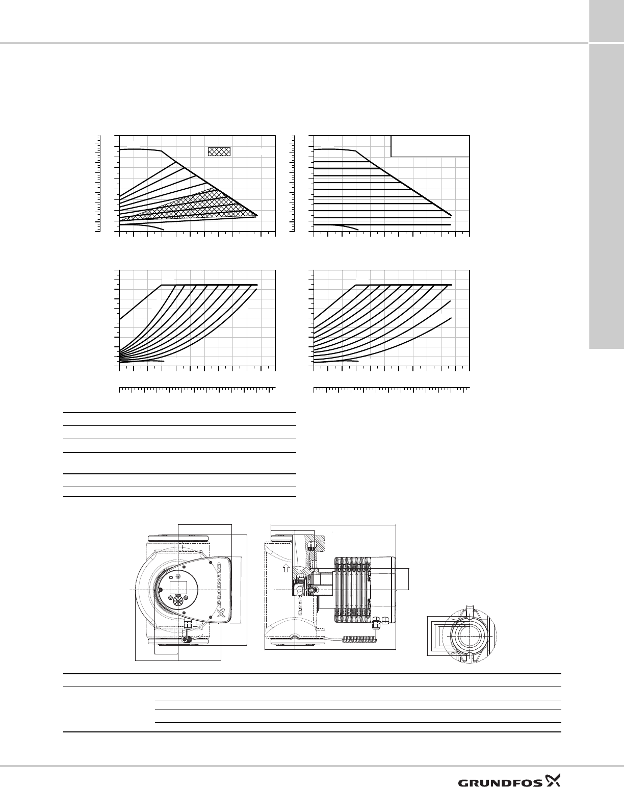
Performance curves and technical data
10
45
MAGNA3 Performance curves and technical data
MAGNA3 40-120 F (N) 1 x 115 & 208-230 V, 50/60 Hz
For product numbers, see page 7.
TM05 8104 1214
0 10 20 30 40 50 60 70 80 Q [US GPM]
0
5
10
15
20
25
30
35
40
45
[ft]
H
0
2
4
6
8
10
12
14
16
18
[psi]
p
MAX
MIN
AUTOADAPT
0 10 20 30 40 50 60 70 80 Q [US GPM]
0
50
100
150
200
250
300
350
400
450
500
[W]
P1
0 2 4 6 8 10 12 14 16 18 20 Q [m³/h]
MAX
MIN
2 m
10m
0 10 20 30 40 50 60 70 80 Q [US GPM]
0
5
10
15
20
25
30
35
40
45
[ft]
H
0
2
4
6
8
10
12
14
16
18
[psi]
p
MAGNA3 40-120 F (N)
MAX
MIN
0 10 20 30 40 50 60 70 80 Q [US GPM]
0
50
100
150
200
250
300
350
400
450
500
[W]
P1
0 2 4 6 8 10 12 14 16 18 20 Q [m³/h]
MAX
MIN
1m
10m
Proportional pressure Constant pressure
Speed I1/1 [A] 115 V P1 [W] 115 V I1/1 [A] 230 V P1 [W] 230 V
Min. 0.26 16 0.19 16
Max. 3.88 442 1.95 440
The pump incorporates overload protection.
Net weights [lbs (kg)] Gross weights [lbs (kg)] Ship. vol. [ft3 (m3)]
35 (15.9) 41 (18.7) 1.41 (0.04)
System pressure: Max. 175 psi (12 bar)
Liquid temperature: 14 to 230 °F (-10 °C to +110 °C)
Also available with: Stainless-steel pump housing, type N
Specific EEI: 0.18
TM05 7651 1413
B2
L5
L1
B7
B4
B6
H3
H1 H6
H4 H2
B1
D4
D3
D2
D1
D5
Pump type Dimensions [in (mm)]
MAGNA3 40-120 F (N)
L1 L5 B1 B2 B4 B6 B7 D1 D2
8.5 (216) 8.03 (204) 3.31 (84) 6.46 (164) 2.87 (73) 4.37 (111) 4.37 (111) 1.57 (40) 1.93 (49)
D3 D4 D5 H1 H2 H3 H4 H6
2.4 (60) 3.15 (80) 0.5 (12.8) - 11.97 (304) - 2.76 (70) 1.97 (50)
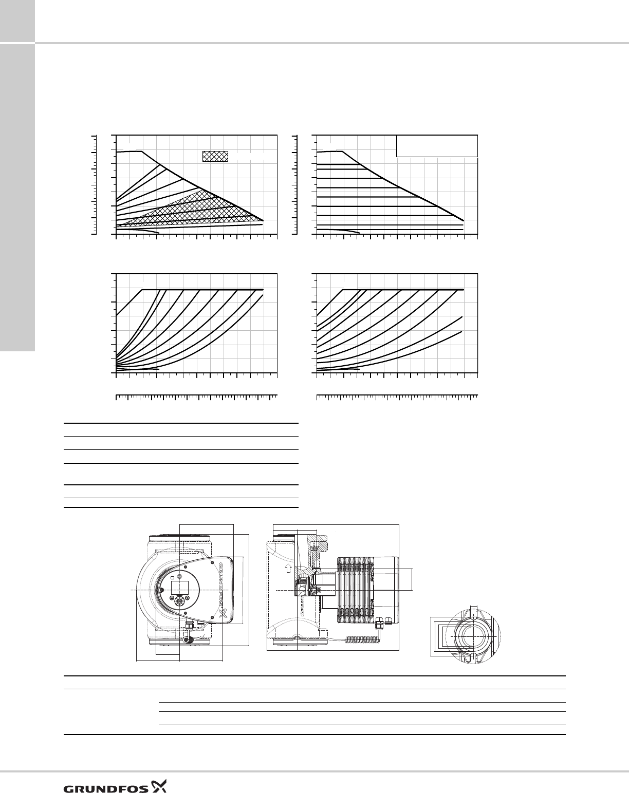
Performance curves and technical data
10
46
MAGNA3Performance curves and technical data
MAGNA3 40-180 F (N) 1 x 115 & 208-230 V, 50/60 Hz
For product numbers, see page 7.
TM05 8105 1214
0 10 20 30 40 50 60 70 80 Q [US GPM]
0
10
20
30
40
50
60
70
[ft]
H
0
5
10
15
20
25
30
[psi]
p
MAX
MIN
AUTOADAPT
0 10 20 30 40 50 60 70 80 Q [US GPM]
0
100
200
300
400
500
600
700
[W]
P1
0 2 4 6 8 10 12 14 16 18 20 22 Q [m³/h]
MAX
MIN
0 10 20 30 40 50 60 70 80 Q [US GPM]
0
10
20
30
40
50
60
70
[ft]
H
0
5
10
15
20
25
30
[psi]
p
MAGNA3 40-180 F (N)
MAX
MIN
0 10 20 30 40 50 60 70 80 Q [US GPM]
0
100
200
300
400
500
600
700
[W]
P1
0 2 4 6 8 10 12 14 16 18 20 22 Q [m³/h]
MAX
MIN
Proportional pressure Constant pressure
Speed I1/1 [A] 115 V P1 [W] 115 V I1/1 [A] 230 V P1 [W] 230 V
Min. 0.26 16 0.18 16
Max. 5.39 614 2.68 607
The pump incorporates overload protection.
Net weights [lbs (kg)] Gross weights [lbs (kg)] Ship. vol. [ft3 (m3)]
35 (15.9) 41 (18.7) 1.41 (0.04)
System pressure: Max. 175 psi (12 bar)
Liquid temperature: 14 to 230 °F (-10 °C to +110 °C)
Also available with: Stainless-steel pump housing, type N
Specific EEI: 0.18
TM05 7651 1413
B2
L5
L1
B7
B4
B6
H3
H1 H6
H4 H2
B1
D4
D3
D2
D1
D5
Pump type Dimensions [in (mm)]
MAGNA3 40-180 F (N)
L1 L5 B1 B2 B4 B6 B7 D1 D2
8.5 (216) 8.03 (204) 3.31 (84) 6.46 (164) 2.87 (73) 4.37 (111) 4.37 (111) 1.57 (40) 1.93 (49)
D3 D4 D5 H1 H2 H3 H4 H6
2.4 (61) 3.15 (80) 0.5 (12.8) - 11.97 (304) - 2.76 (70) 1.97 (50)
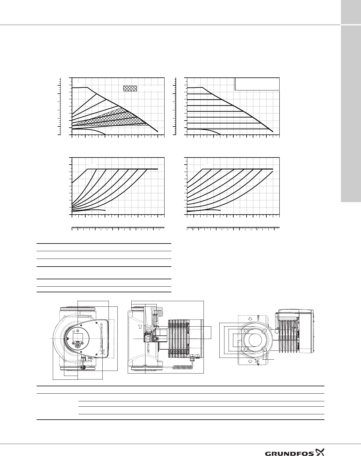
Performance curves and technical data
10
47
MAGNA3 Performance curves and technical data
MAGNA3 50-80 F (N) 1 x 115 & 208-230 V, 50/60 Hz
For product numbers, see page 7.
TM05 8106 1214
0 10 20 30 40 50 60 70 80 90 100 Q [US GPM]
0
4
8
12
16
20
24
28
32
[ft]
H
0
2
4
6
8
10
12
[psi]
p
MAX
MIN
AUTOADAPT
0 10 20 30 40 50 60 70 80 90 100 Q [US GPM]
0
50
100
150
200
250
300
350
400
[W]
P1
0 2 4 6 8 10 12 14 16 18 20 22 24 26Q [m³/h]
MAX
MIN
0 10 20 30 40 50 60 70 80 90 100 Q [US GPM]
0
4
8
12
16
20
24
28
32
[ft]
H
0
2
4
6
8
10
12
[psi]
p
MAGNA3 50-80 F (N)
MAX
MIN
0 10 20 30 40 50 60 70 80 90 100 Q [US GPM]
0
50
100
150
200
250
300
350
400
[W]
P1
0 2 4 6 8 10 12 14 16 18 20 22 24 26Q [m³/h]
MAX
MIN
Proportional pressure Constant pressure
Speed I1/1 [A] 115 V P1 [W] 115 V I1/1 [A] 230 V P1 [W] 230 V
Min. 0.31 18.5 0.22 18.5
Max. 2.81 318 1.46 325
The pump incorporates overload protection.
Net weights [lbs (kg)] Gross weights [lbs (kg)] Ship. vol. [ft3 (m3)]
37 (17.0) 45 (20.4) 1.77 (0.05)
System pressure: Max. 175 psi (12 bar)
Liquid temperature: 14 to 230 °F (-10 °C to +110 °C)
Also available with: Stainless-steel pump housing, type N
Specific EEI: 0.18
TM05 7652 1413
B2
L5
L1
B7
B4
B6
H3
H1 H6
H4 H2
B1
D1
D2
D3
D4
ØD5
Pump type Dimensions [in (mm)]
MAGNA3 50-80 F (N)
L1 L5 B1 B2 B4 B6 B7 D1 D2
9.45 (240) 8.03 (204) 3.31 (84) 6.46 (164) 2.87 (73) 5 (127) 5 (127) 1.97 (50) 3.90 (99)
D3 D4 D5 H1 H2 H3 H4 H6
4.33/4.92 (110/125) 6.5 (165) 0.55/0.75 (14/19) 2.8 (71) 12.05 (306) 14.84 (377) 3.82 (97) 2.05 (52)
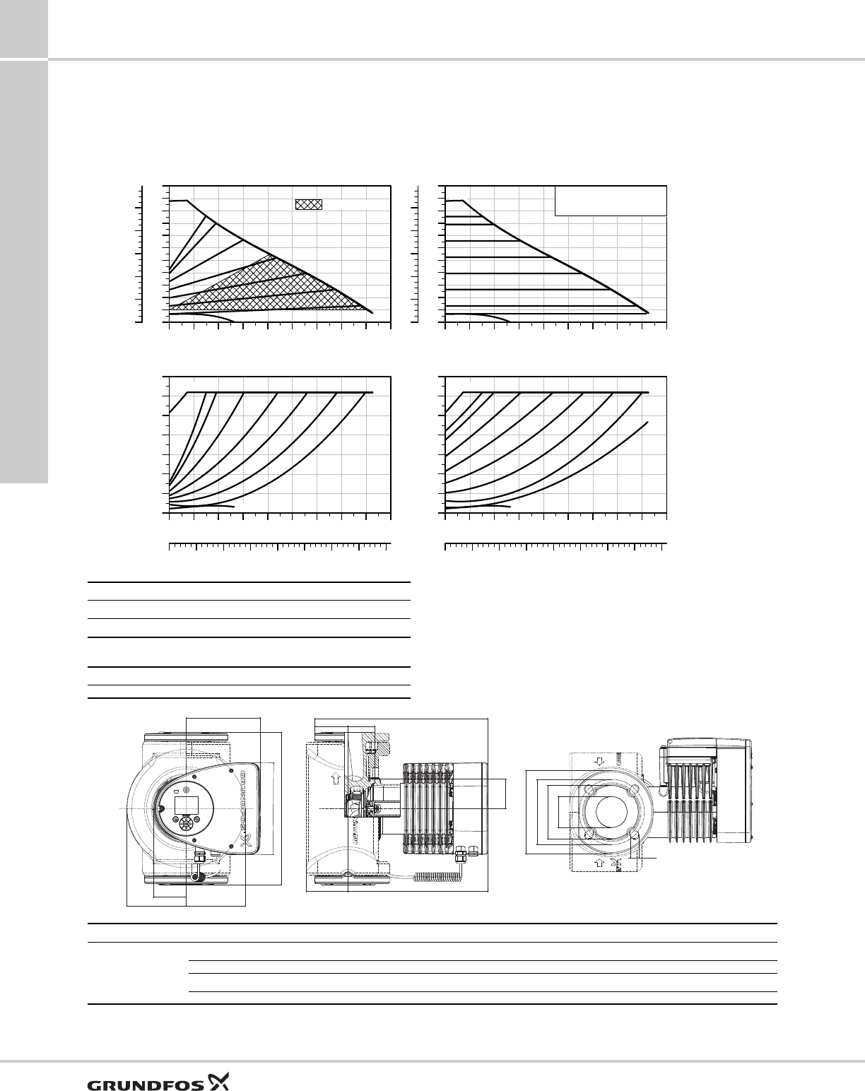
Performance curves and technical data
10
48
MAGNA3Performance curves and technical data
MAGNA3 50-150 F (N) 1 x 115 & 208-230 V, 50/60 Hz
For product numbers, see page 7.
TM05 8107 1214
0 20 40 60 80 100 120 Q [US GPM]
0
5
10
15
20
25
30
35
40
45
50
55
[ft]
H
0
4
8
12
16
20
[psi]
p
MAX
MIN
AUTOADAPT
0 20 40 60 80 100 120 Q [US GPM]
0
100
200
300
400
500
600
700
[W]
P1
0 5 10 15 20 25 30 Q [m³/h]
MAX
MIN
0 20 40 60 80 100 120 Q [US GPM]
0
5
10
15
20
25
30
35
40
45
50
55
[ft]
H
0
4
8
12
16
20
[psi]
p
MAGNA3 50-150 F (N)
MAX
MIN
0 20 40 60 80 100 120 Q [US GPM]
0
100
200
300
400
500
600
700
[W]
P1
0 5 10 15 20 25 30 Q [m³/h]
MAX
MIN
Proportional pressure Constant pressure
Speed I1/1 [A] 115 V P1 [W] 115 V I1/1 [A] 230 V P1 [W] 230 V
Min. 0.31 18.5 0.23 18.5
Max. 5.54 630 2.78 630
The pump incorporates overload protection.
Net weights [lbs (kg)] Gross weights [lbs (kg)] Ship. vol. [ft3 (m3)]
40 (18.3) 49 (22.0) 1.77 (0.05)
System pressure: Max. 175 psi (12 bar)
Liquid temperature: 14 to 230 °F (-10 °C to +110 °C)
Also available with: Stainless-steel pump housing, type N
Specific EEI: 0.17
TM05 7652 1413
B2
L5
L1
B7
B4
B6
H3
H1 H6
H4 H2
B1
D1
D2
D3
D4
ØD5
Pump type Dimensions [in (mm)]
MAGNA3 50-150 F (N)
L1 L5 B1 B2 B4 B6 B7 D1 D2
11.02 (280) 8.03 (204) 3.31 (84) 6.46 (164) 2.87 (73) 5 (127) 5 (127) 1.97 (50) 3.90 (99)
D3 D4 D5 H1 H2 H3 H4 H6
4.33/4.92 (110/125) 6.5 (165) 0.55/0.75 (14/19) 2.83 (72) 12.05 (306) 14.9 (378) 3.82 (97) 2.05 (52)
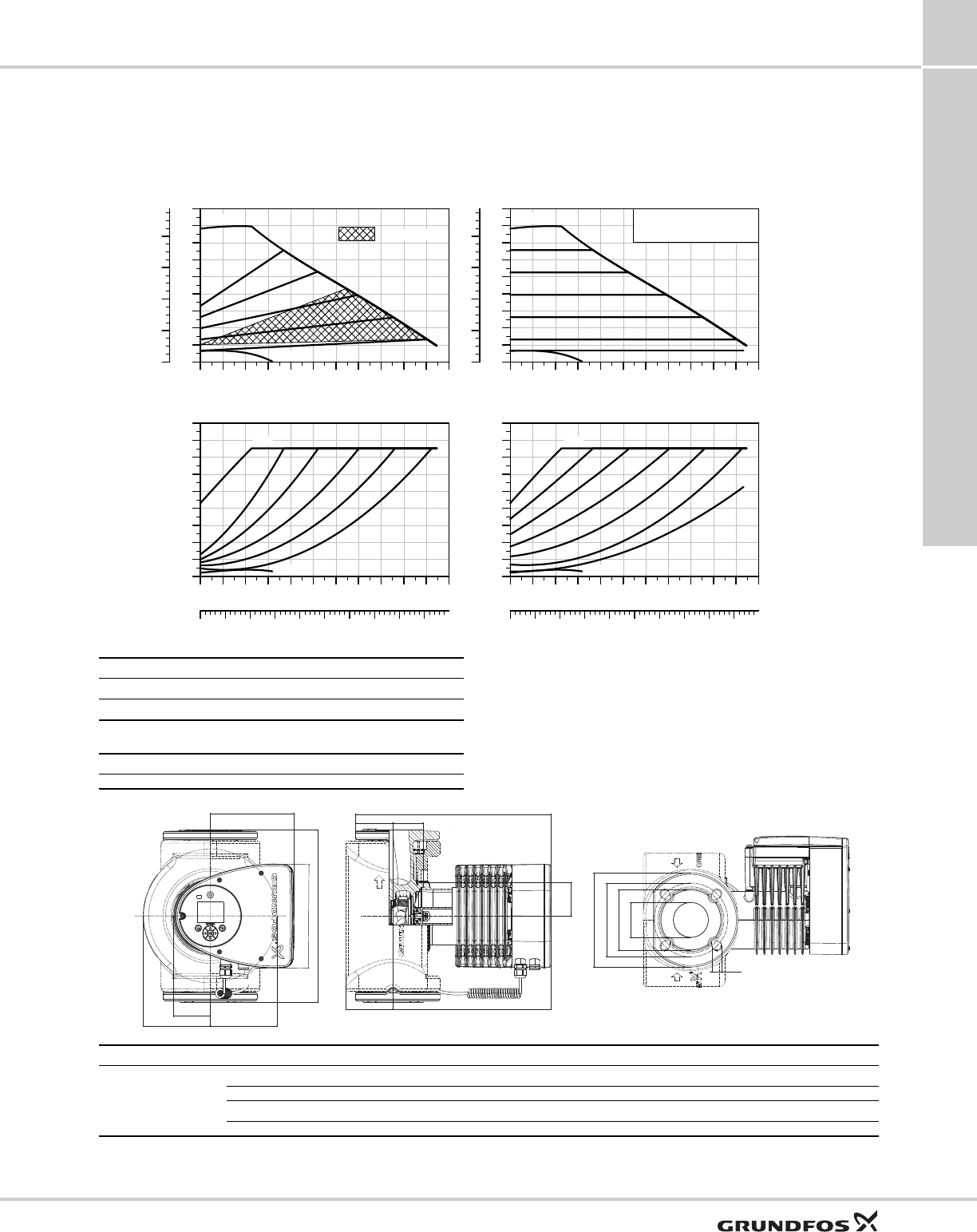
Performance curves and technical data
10
49
MAGNA3 Performance curves and technical data
MAGNA3 65-120 F (N) 1 x 115 & 208-230 V, 50/60 Hz
For product numbers, see page 7.
TM05 8108 1214
0 20 40 60 80 100 120 140 160Q [US GPM]
0
5
10
15
20
25
30
35
40
45
[ft]
H
0
4
8
12
16
[psi]
p
MAX
MIN
AUTOADAPT
0 20 40 60 80 100 120 140 160Q [US GPM]
0
100
200
300
400
500
600
700
800
900
[W]
P1
0 5 10 15 20 25 30 35 40 Q [m³/h]
MAX
MIN
0 20 40 60 80 100 120 140 Q [US GPM]
0
5
10
15
20
25
30
35
40
45
[ft]
H
0
4
8
12
16
[psi]
p
MAGNA3 65-120 F (N)
MAX
MIN
0 20 40 60 80 100 120 140 Q [US GPM]
0
100
200
300
400
500
600
700
800
900
[W]
P1
0 5 10 15 20 25 30 35 40 Q [m³/h]
MAX
MIN
Proportional pressure Constant pressure
Speed I1/1 [A] 115 V P1 [W] 115 V I1/1 [A] 230 V P1 [W] 230 V
Min. 0.36 20.5 0.18 20.5
Max. 6.67 772 3.38 769
The pump incorporates overload protection.
Net weights [lbs (kg)] Gross weights [lbs (kg)] Ship. vol. [ft3 (m3)]
46 (21.0) 54 (24.7) 2.12 (0.06)
System pressure: Max. 175 psi (12 bar)
Liquid temperature: 14 to 230 °F (-10 °C to +110 °C)
Also available with: Stainless-steel pump housing, type N
Specific EEI: 0.17
TM05 7652 1413
B2
L5
L1
B7
B4
B6
H3
H1 H6
H4 H2
B1
D1
D2
D3
D4
ØD5
Pump type Dimensions [in (mm)]
MAGNA3 65-120 F (N)
L1 L5 B1 B2 B4 B6 B7 D1 D2
13.4 (340) 8.03 (204) 3.31 (84) 6.46 (164) 2.87 (73) 5.24 (133) 5.24 (133) 2.56 (65) 4.65 (118)
D3 D4 D5 H1 H2 H3 H4 H6
5.0/5.51 (127/140) 7.28 (185) 0.63/0.75 (16/19) 2.91 (74) 12.28 (312) 15.2 (386) 3.7 (94) 2.32 (59)
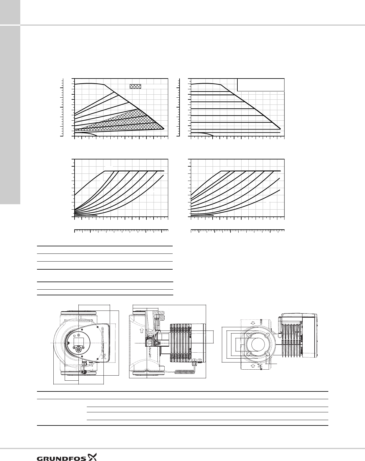
Performance curves and technical data
10
50
MAGNA3Performance curves and technical data
MAGNA3 65-150 F (N) 1 x 208-230 V, 50/60 Hz
For product numbers, see page 7.
TM05 8109 1214
0 20 40 60 80 100 120140 160180 Q [US GPM]
0
5
10
15
20
25
30
35
40
45
50
55
[ft]
H
0
4
8
12
16
20
[psi]
p
MAX
MIN
AUTOADAPT
0 20 40 60 80 100 120140 160180 Q [US GPM]
0
200
400
600
800
1000
1200
1400
1600
[W]
P1
0 5 10 15 20 25 30 35 40 45 Q [m³/h]
MAX
MIN
2m
13m
0 20 40 60 80 100120 140 160180 Q [US GPM]
0
5
10
15
20
25
30
35
40
45
50
55
[ft]
H
0
4
8
12
16
20
[psi]
p
MAGNA3 65-150 F (N)
MAX
MIN
0 20 40 60 80 100120 140 160180 Q [US GPM]
0
200
400
600
800
1000
1200
1400
1600
[W]
P1
0 5 10 15 20 25 30 35 40 45 Q [m³/h]
MAX
MIN
1m
13m
Proportional pressure Constant pressure
Speed P1 [W] I1/1 [A]
Min. 29 0.30
Max. 1301 5.68
The pump incorporates overload protection.
Net weights [lbs (kg)] Gross weights [lbs (kg)] Ship. vol. [ft3 (m3)]
53 (24.0) 61 (27.8) 2.12 (0.06)
System pressure: Max. 175 psi (12 bar)
Liquid temperature: 14 to 230 °F (-10 °C to +110 °C)
Also available with: Stainless-steel pump housing, type N
Specific EEI: 0.17
TM05 7652 1413
B2
L5
L1
B7
B4
B6
H3
H1 H6
H4 H2
B1
D1
D2
D3
D4
ØD5
Pump type Dimensions [in (mm)]
MAGNA3 65-150 F (N)
L1 L5 B1 B2 B4 B6 B7 D1 D2
13.4 (340) 8.03 (204) 3.31 (84) 6.46 (164) 2.87 (73) 5.24 (133) 5.24 (133) 2.56 (65) 4.65 (118)
D3 D4 D5 H1 H2 H3 H4 H6
5.0/5.51 (127/140) 7.28 (185) 0.63/0.75 (16/19) 2.91 (74) 12.28 (312) 15.2 (386) 3.7 (94) 2.32 (59)
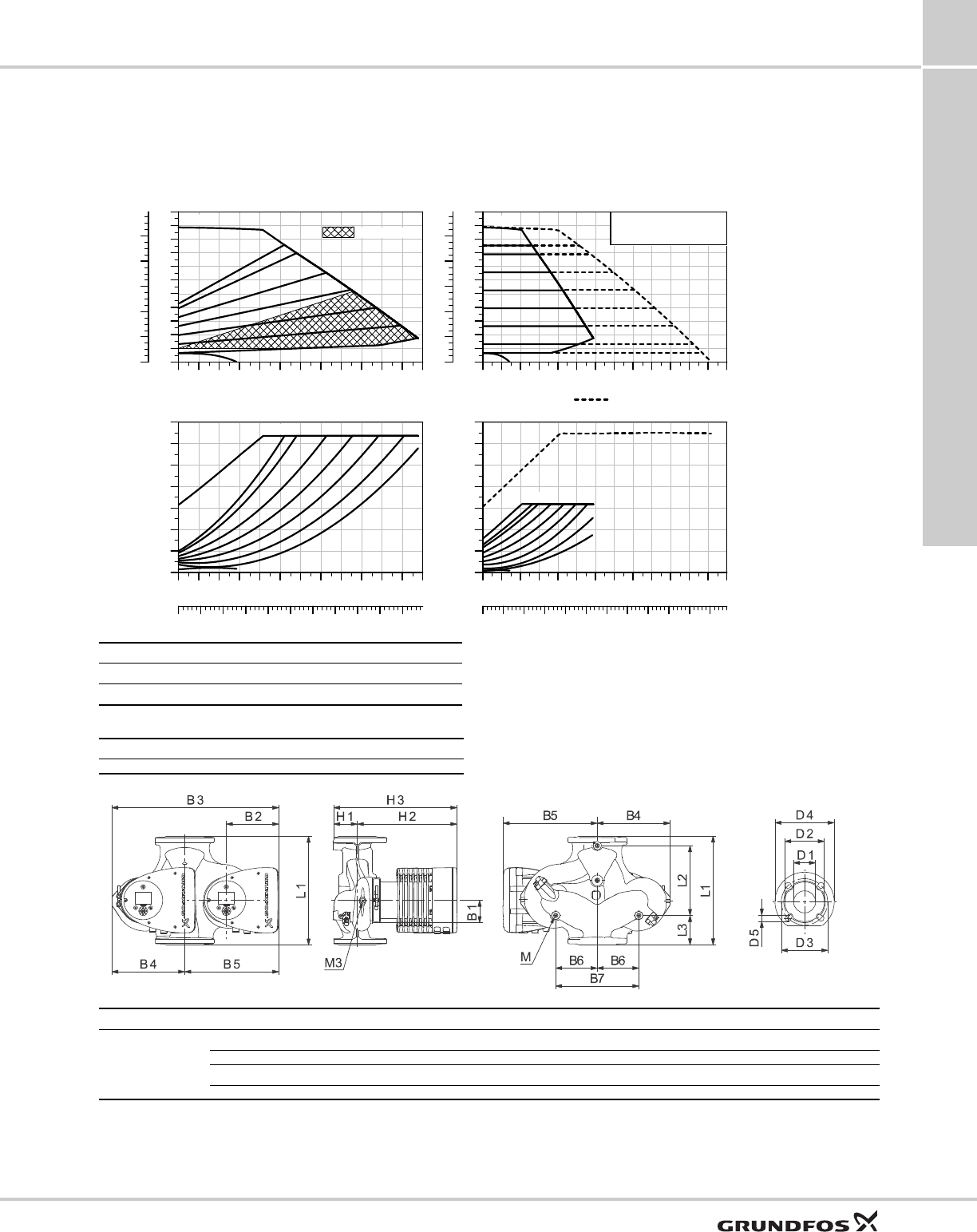
Performance curves and technical data
10
51
MAGNA3 Performance curves and technical data
MAGNA3 D 65-150 F 1 x 208-230 V, 50/60 Hz
For product numbers, see page 7.
TM05 8112 1214
0 20 40 60 80 100 120 140 160 Q [US GPM]
0
5
10
15
20
25
30
35
40
45
50
55
[ft]
H
0
4
8
12
16
20
[psi]
p
MAX
MIN
AUTOADAPT
0 20 40 60 80 100 120 140 160 Q [US GPM]
0
200
400
600
800
1000
1200
1400
[W]
P1
0 5 10 15 20 25 30 35 40 Q [m³/h]
MAX
MIN
0 40 80 120160 200240 280320 360 Q [US GPM]
0
5
10
15
20
25
30
35
40
45
50
55
[ft]
H
0
4
8
12
16
20
[psi]
p
MAGNA3 D 65-150 F
MAX
Constant Pressure Cascade
0 40 80 120160 200240 280320 360 Q [US GPM]
0
400
800
1200
1600
2000
2400
2800
[W]
P1
0 10 20 30 40 50 60 70 80 90 Q [m³/h]
MAX
Proportional pressure Constant pressure
Speed P1 [W] I1/1 [A]
Min. 29 0.30
Max. 1301 5.68
The pump incorporates overload protection.
Net weights [lbs (kg)] Gross weights [lbs (kg)] Ship. vol. [ft3 (m3)]
98 (44.6) 118 (53.7) 2.12 (0.06)
System pressure: Max. 175 psi (12 bar)
Liquid temperature: 14 to 230 °F (-10 °C to +110 °C)
Specific EEI: 0.17
TM05 2205 2214
Pump type Dimensions [in (mm)]
MAGNA3 D 65-150 F
L1 L2 L3 L4 L5 B1 B3 B4 B5
13.4 (340) 8.58 (218) 3.62 (92) 3.62 (92) 8.03 (204) 3.31 (84) 20.55 (522) 8.98 (228) 11.57 (294)
D1 D2 D3 D4 D5 D5 (2) M M1 H1
2.56 (65) 4.69 (119) 5.12/5.71 (130/145) 7.28 (185) 0.55 (14) 0.75 (19) M12 Rp 1/4 3.03 (77)
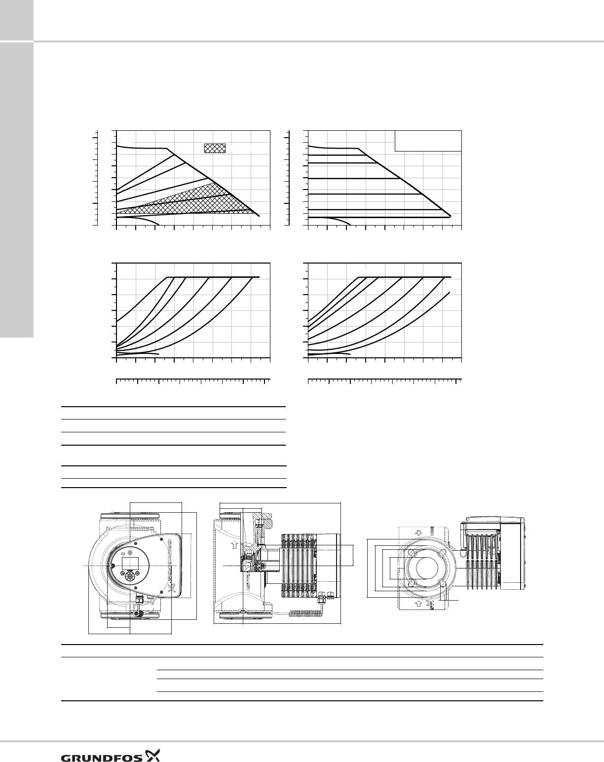
Performance curves and technical data
10
52
MAGNA3Performance curves and technical data
MAGNA3 80-100 F 1 x 208-230 V, 50/60 Hz
For product numbers, see page 7.
TM05 8110 1214
0 40 80 120 160 200 Q [US GPM]
0
5
10
15
20
25
30
35
40
[ft]
H
0
4
8
12
16
[psi]
p
MAX
MIN
AUTOADAPT
0 40 80 120 160 200 Q [US GPM]
0
200
400
600
800
1000
1200
[W]
P1
0 10 20 30 40 50 Q [m³/h]
MAX
MIN
0 40 80 120 160 200 Q [US GPM]
0
5
10
15
20
25
30
35
40
[ft]
H
0
4
8
12
16
[psi]
p
MAGNA3 80-100 F
MAX
MIN
0 40 80 120 160 200 Q [US GPM]
0
200
400
600
800
1000
1200
[W]
P1
0 10 20 30 40 50 Q [m³/h]
MAX
MIN
Proportional pressure Constant pressure
Speed P1 [W] I1/1 [A]
Min. 31 0.32
Max. 1041 4.60
The pump incorporates overload protection.
Net weights [lbs (kg)] Gross weights [lbs (kg)] Ship. vol. [ft3 (m3)]
63 (28.8) 72 (32.6) 2.47 (0.07)
System pressure: Max. 175 psi (12 bar)
Liquid temperature: 14 to 230 °F (-10 °C to +110 °C)
Specific EEI: 0.17
TM05 7652 1413
B2
L5
L1
B7
B4
B6
H3
H1 H6
H4 H2
B1
D1
D2
D3
D4
ØD5
Pump type Dimensions [in (mm)]
MAGNA3 80-100 F (N)
L1 L5 B1 B2 B4 B6 B7 D1 D2
14.17 (360) 8.03 (204) 3.31 (84) 6.46 (164) 2.87 (73) 6.42 (163) 6.42 (163) 3.15 (80) 5.2 (132)
D3 D4 D5 H1 H2 H3 H4 H6
5.91 (150) 7.87 (200) 0.75 (19) 3.7 (94) 12.52 (318) 16.22 (412) 4.53 (115) 2.6 (66)
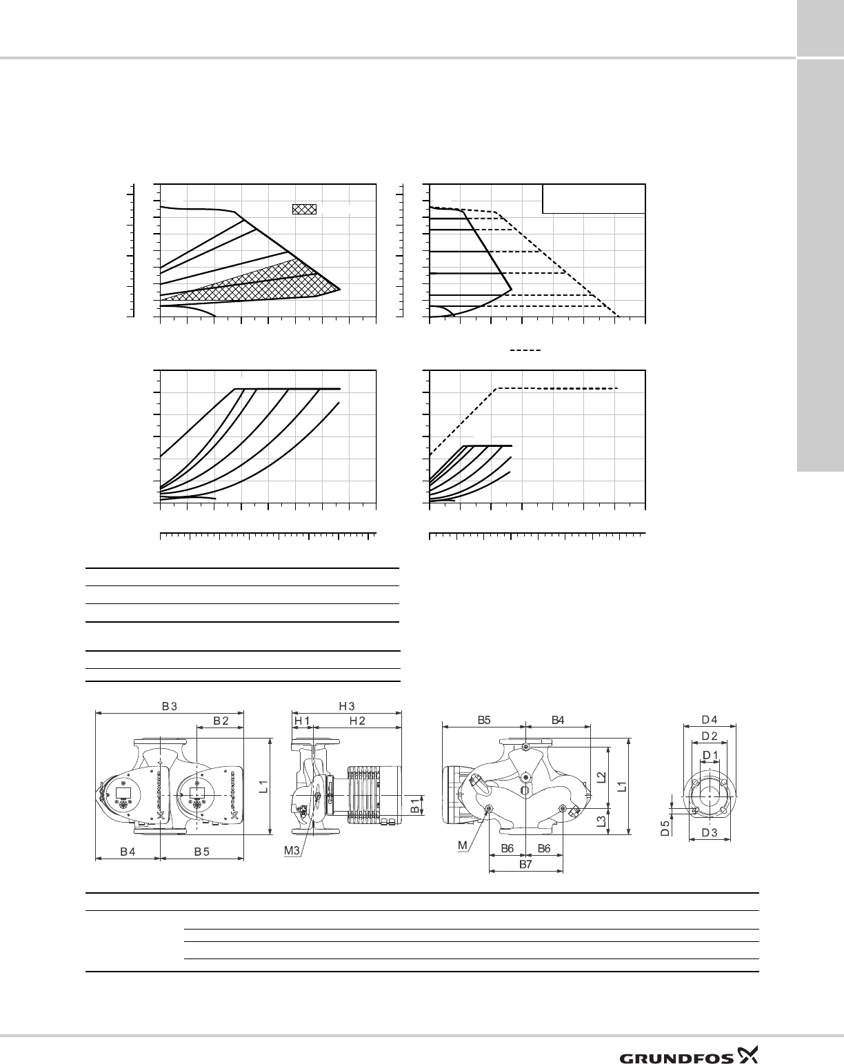
Performance curves and technical data
10
53
MAGNA3 Performance curves and technical data
MAGNA3 D 80-100 F 1 x 208-230 V, 50/60 Hz
For product numbers, see page 7.
TM05 8113 1913
0 40 80 120 160 200 Q [US GPM]
0
5
10
15
20
25
30
35
40
[ft]
H
0
4
8
12
16
[psi]
p
MAX
MIN
AUTOADAPT
0 40 80 120 160 200 Q [US GPM]
0
200
400
600
800
1000
1200
[W]
P1
0 10 20 30 40 50 Q [m³/h]
MAX
MIN
0 100 200 300 400 500 Q [US GPM]
0
5
10
15
20
25
30
35
40
[ft]
H
0
4
8
12
16
[psi]
p
MAGNA3 D 80-100 F
MAX
Constant Pressure Cascade
0 100 200 300 400 500 Q [US GPM]
0
400
800
1200
1600
2000
2400
[W]
P1
0 20 40 60 80 100 120 Q [m³/h]
MAX
Proportional pressure Constant pressure
Speed P1 [W] I1/1 [A]
Min. 32 0.32
Max. 1052 4.62
The pump incorporates overload protection.
Net weights [lbs (kg)] Gross weights [lbs (kg)] Ship. vol. [ft3 (m3)]
114 (51.6) 140 (63.4) 2.47 (0.07)
System pressure: Max. 175 psi (12 bar)
Liquid temperature: 14 to 230 °F (-10 °C to +110 °C)
Specific EEI: 0.17
TM05 2205 2214
Pump type Dimensions [in (mm)]
MAGNA3 D 80-100 F
L1 L2 L3 L4 L5 B1 B3 B4 B5
14.17 (360) 8.58 (218) 4.02 (102) 4.02 (102) 8.03 (204) 3.31 (84) 21.18 (538) 9.61 (244) 11.57 (294)
D1 D2 D3 D3 (2) D4 D5 M M1 H1
3.15 (80) 5.04 (128) 5.91 (150) 6.30 (160) 7.87 (200) 0.75 (19) M12 Rp 1/4 3.82 (97)
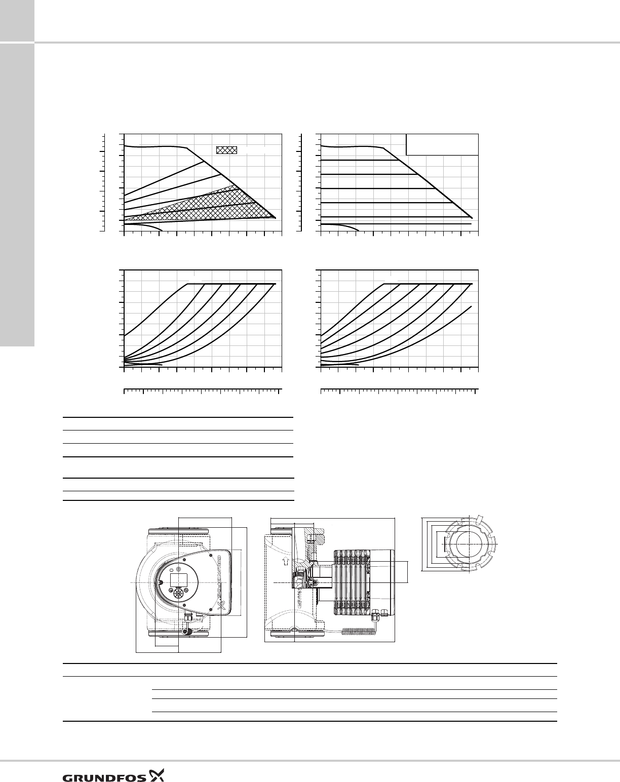
Performance curves and technical data
10
54
MAGNA3Performance curves and technical data
MAGNA3 100-120 F 1 x 208-230 V, 50/60 Hz
For product numbers, see page 7.
TM05 8111 1214
0 40 80 120 160 200 240 Q [US GPM]
0
5
10
15
20
25
30
35
40
45
[ft]
H
0
4
8
12
16
[psi]
p
MAX
MIN
AUTOADAPT
0 40 80 120 160 200 240 Q [US GPM]
0
200
400
600
800
1000
1200
1400
1600
1800
[W]
P1
0 10 20 30 40 50 60 Q [m³/h]
MAX
MIN
0 40 80 120 160 200 240 Q [US GPM]
0
5
10
15
20
25
30
35
40
45
[ft]
H
0
4
8
12
16
[psi]
p
MAGNA3 100-120 F
MAX
MIN
0 40 80 120 160 200 240 Q [US GPM]
0
200
400
600
800
1000
1200
1400
1600
1800
[W]
P1
0 10 20 30 40 50 60 Q [m³/h]
MAX
MIN
Proportional pressure Constant pressure
Speed P1 [W] I1/1 [A]
Min. 31 0.32
Max. 1576 6.97
The pump incorporates overload protection.
Net weights [lbs (kg)\ Gross weights [lbs (kg)] Ship. vol. [ft3 (m3)]
73 (33.1) 82 (37.0) 3.53 (0.1)
System pressure: Max. 175 psi (12 bar)
Liquid temperature: 14 to 230 °F (-10 °C to +110 °C)
Specific EEI: 0.17
TM05 7650 1413
B2
L5
L1
B7
B4
B6
H3
H1 H6
H4 H2
B1
D4
D3
D2
D1
D5
Pump type Dimensions [in (mm)]
MAGNA3 100-120 F (N)
L1 L5 B1 B2 B4 B6 B7 D1 D2
17.72 (450) 8.03 (204) 3.31 (84) 6.46 (164) 2.87 (73) 7.01 (178) 7.01 (178) 3.94 (100) 6.14 (156)
D3 D4 D5 H1 H2 H3 H4 H6
7.52 (191) 8.66 (220) 0.75 (19) 4.02 (102) 12.99 (330) 17.01 (432) 4.72 (120) 3.11 (79)
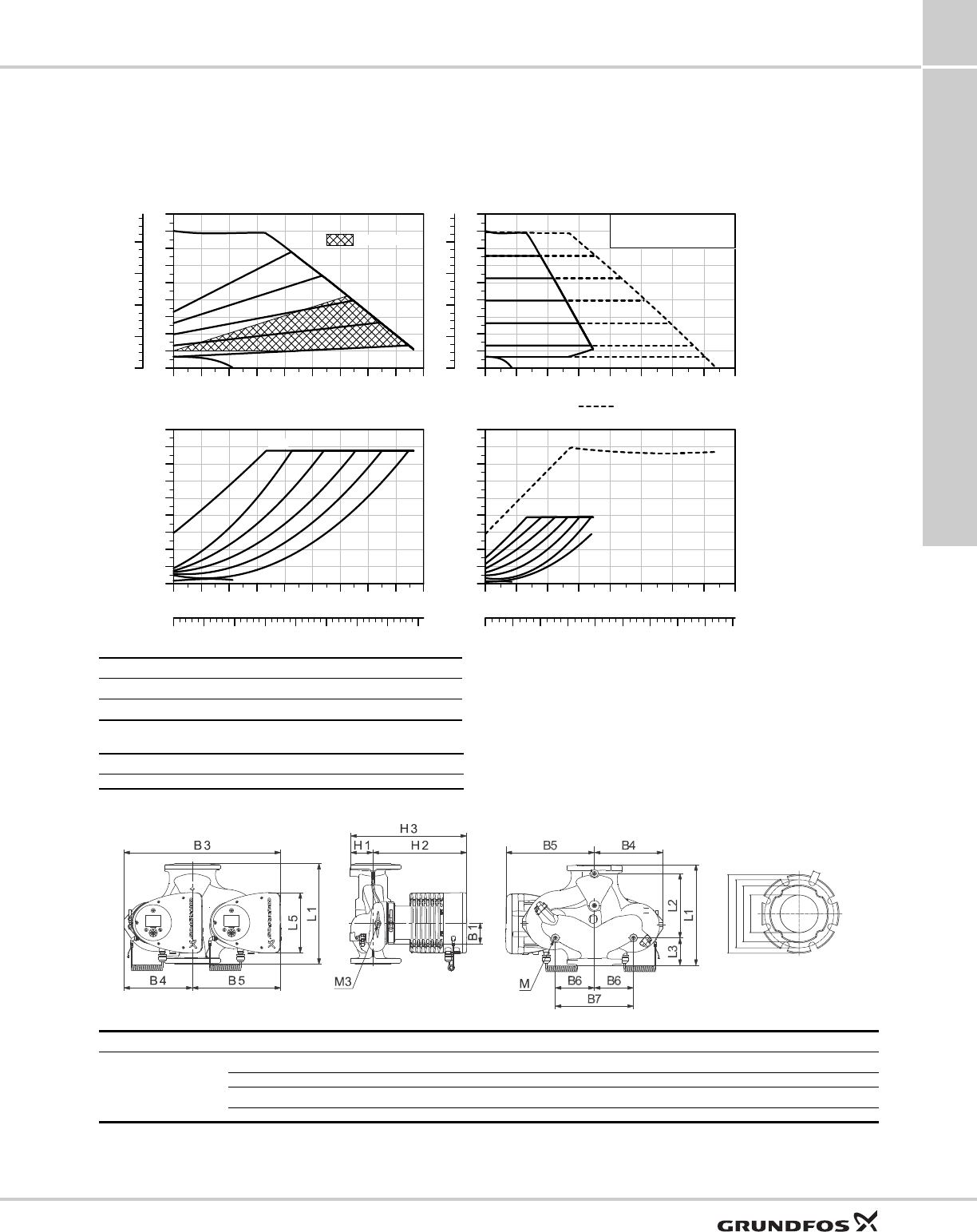
Performance curves and technical data
10
55
MAGNA3 Performance curves and technical data
MAGNA3 D 100-120 F 1 x 208-230 V, 50/60 Hz
For product numbers, see page 7.
TM05 8121 1913
0 40 80 120 160 200 240 Q [US GPM]
0
5
10
15
20
25
30
35
40
45
[ft]
H
0
4
8
12
16
[psi]
p
MAX
MIN
AUTOADAPT
0 40 80 120 160 200 240 Q [US GPM]
0
200
400
600
800
1000
1200
1400
1600
1800
[W]
P1
0 10 20 30 40 50 60 Q [m³/h]
MAX
MIN
0 100 200 300 400 500 Q [US GPM]
0
5
10
15
20
25
30
35
40
45
[ft]
H
0
4
8
12
16
[psi]
p
MAGNA3 D 100-120 F
MAX
Constant Pressure Cascade
0 100 200 300 400 500 Q [US GPM]
0
400
800
1200
1600
2000
2400
2800
3200
3600
[W]
P1
0 20 40 60 80 100 120 140 Q [m³/h]
MAX
Proportional pressure Constant pressure
Speed P1 [W] I1/1 [A]
Min. 35 0.35
Max. 1582 6.98
The pump incorporates overload protection.
Net weights [lbs (kg)] Gross weights [lbs (kg)] Ship. vol. [ft3 (m3)]
133 (60.4) 161 (72.8) 3.53 (0.1)
System pressure: Max. 175 psi (12 bar)
Liquid temperature: 14 to 230 °F (-10 °C to +110 °C)
Specific EEI: 0.17
TM05 7701 1214
D4
D3
D2
D1
D5
Pump type Dimensions [in (mm)]
MAGNA3 D 100-120 F
L1 L2 L3 L4 L5 B1 B3 B4 B5
17.72 (450) 9.57 (243) 5.79 (147) 5.79 (147) 8.03 (204) 3.31 (84) 21.69 (551) 9.92 (252) 11.77 (299)
D1 D2 D3 D4 D5 M M1 H1 H2
3.94 (100) 6.3 (160) 6.69 (170) 8.66 (220) 0.75 (19) M12 Rp 1/4 4.06 (103) 12.99 (330)

Performance curves and technical data
10
56
MAGNA3Performance curves and technical data
Technical data
Electrical data
Sound pressure data
External sensors
Adapters
Blanking flange*
* A blanking flange is used to blank off the opening when one of the
pumps of a twin-head pump is removed for service to enable
uninterrupted operation of the other pump.
Pump type MAGNA3 (D)
Enclosure class Type 2
Insulation class F.
Supply voltage 1 x 115 V ± 10 %, 50/60 Hz, PE; 1 x 208-230 V ± 10 %, 50/60 Hz, PE
Two digital inputs
External potential-free contact.
Contact load: 5 V, 10 mA.
Screened cable.
Loop resistance: Maximum 130 Ω.
Analog input 4-20 mA (load: 150 Ω).
0-10 VDC (load: > 10 kΩ).
Two relay outputs
Internal potential-free changeover contact.
Maximum load: 250 V, 2 A, AC1.
Minimum load: 5 VDC, 20 mA.
Screened cable, depending on signal level.
Bus input
Grundfos Communication Interface Modules (add-on CIM modules) for
•GENIbus
• LonWorks
•Profibus DP
•Modbus RTU
• BACnet MS/TP
• Grundfos Remote Management.
Earth leakage current Ileakage < 3.5 mA.
The leakage currents are measured in accordance with EN 60335-1.
EMC EN 55014-1:2006, EN 55014-2:1998, EN 61800-3-3:2008 and EN 61000-3-2:2006.
cos φThe MAGNA3 has a built-in active PFC (Power Factor Control) which gives a cos φ from 0.98 to 0.99, i.e. very close to 1.
Consumption then the pump is stopped 1 to 10 W, depending on activity, i.e. reading the display, use of Grundfos GO Remote, interaction with modules, etc.
4 W, when pump is stopped and no activity.
Sound pressure level ≤ 43 dB(A)
Sensor Type Measuring range
[°F (°C)] Power supply
[VDC] Transmitter output
[V] Process connection Product
number
Delta T sensor RPI/T +32 to +248 °F
(0 to +120 °C) 11 to 30 0 - 10 V G1/2 - 1/2" NPT 98477669
G1/2 - 1/4" NPT 98477668
Sensor Type Measuring range
[psi] Measuring range
[bar] Transmitter output
[mA] Power supply
[VDC] Process
connection Product number
Pressure
transmitter RPI
0-9 (0 - 0.6)
4 to 20 12-to 30 G 1/2
97748907
0-15 (0 - 1.0) 97748908
0-25 (0 - 1.6) 97748909
0-35 (0 - 2.5) 97748910
Adapter
Adapter for 1/4" NPT 98344015
Adapter for 1/4" NPT 98255244
Blanking flange Product number
All pumps 98159372
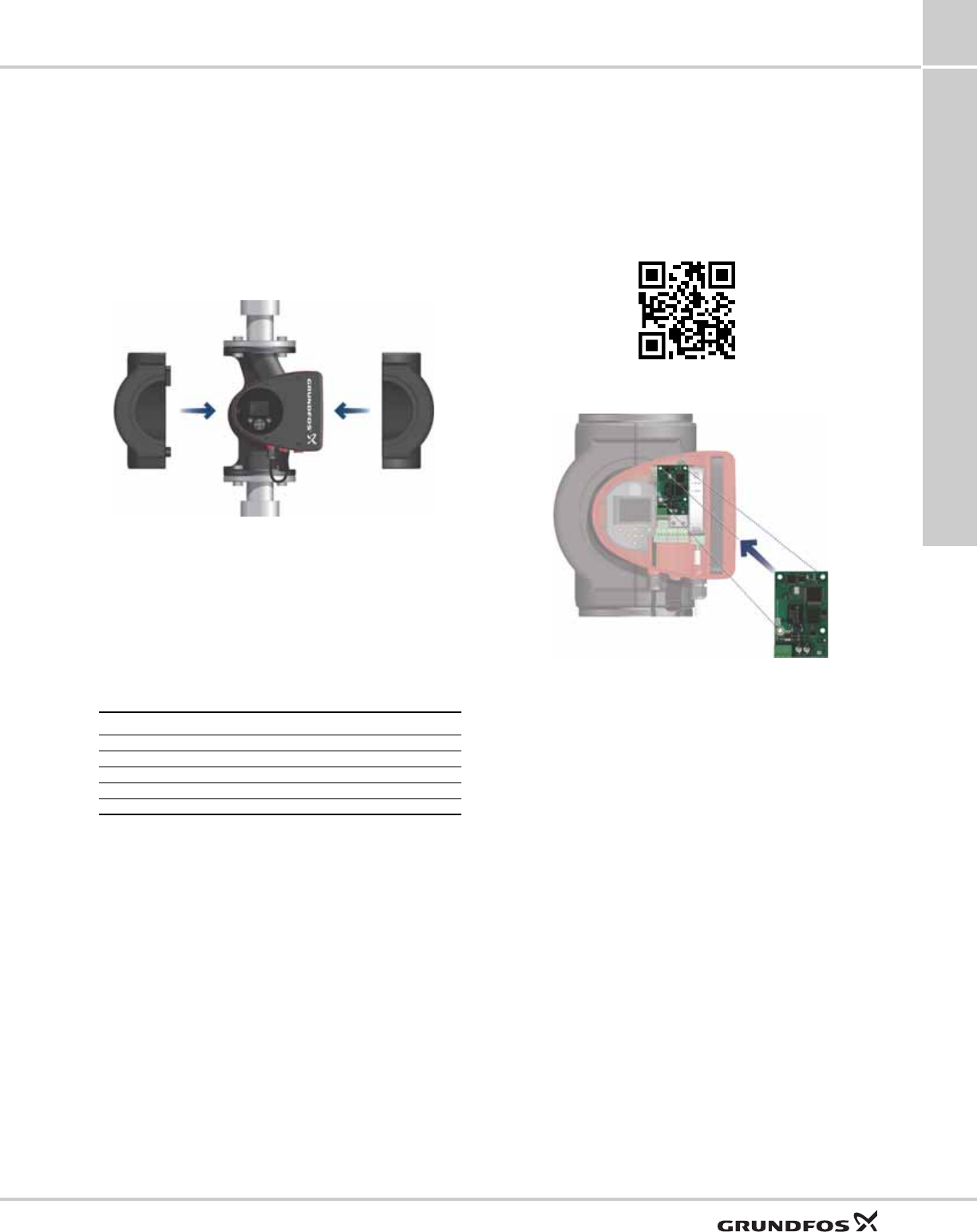
Accessories
MAGNA3 11
57
11. Accessories
Insulating for air-conditioning and
cooling systems
For cooling applications, if the supplied insulation shell
is to be used then a silicon sealant must be liberally
applied to the inside of the insulation shell to ensure all
air gaps are eliminated between the shell and pump
housing to prevent condensation inside the shell.
Fig. 57 Fitting the insulating shells to a MAGNA3 pump
CIM modules
A CIM module is an add-on Communication Interface
Module. The CIM module enables data transmission
between the pump and an external system, for
example a BMS or SCADA system.
The CIM module communicates via fieldbus protocols.
The following CIM modules are available:
For further information about data communication via
CIM modules, see the CIM documentation available in
WebCAPS.
Location of CIM module
The CIM module is fitted behind the front cover. See
fig. 58.
For installation, see separate installation and operating
instructions.
Fig. 58 Location of CIM module
TM05 2874 0412
Module Fieldbus protocol Product number
CIM 050 GENIbus 96824631
CIM 100 LonWorks 96824797
CIM 150 Profibus DP 96824793
CIM 200 Modbus RTU 96824796
CIM 300 BACnet MS/TP 96893770
http://GRUNDFOS.COM/MANUAL-MAGNA3
TM05 2914 1112
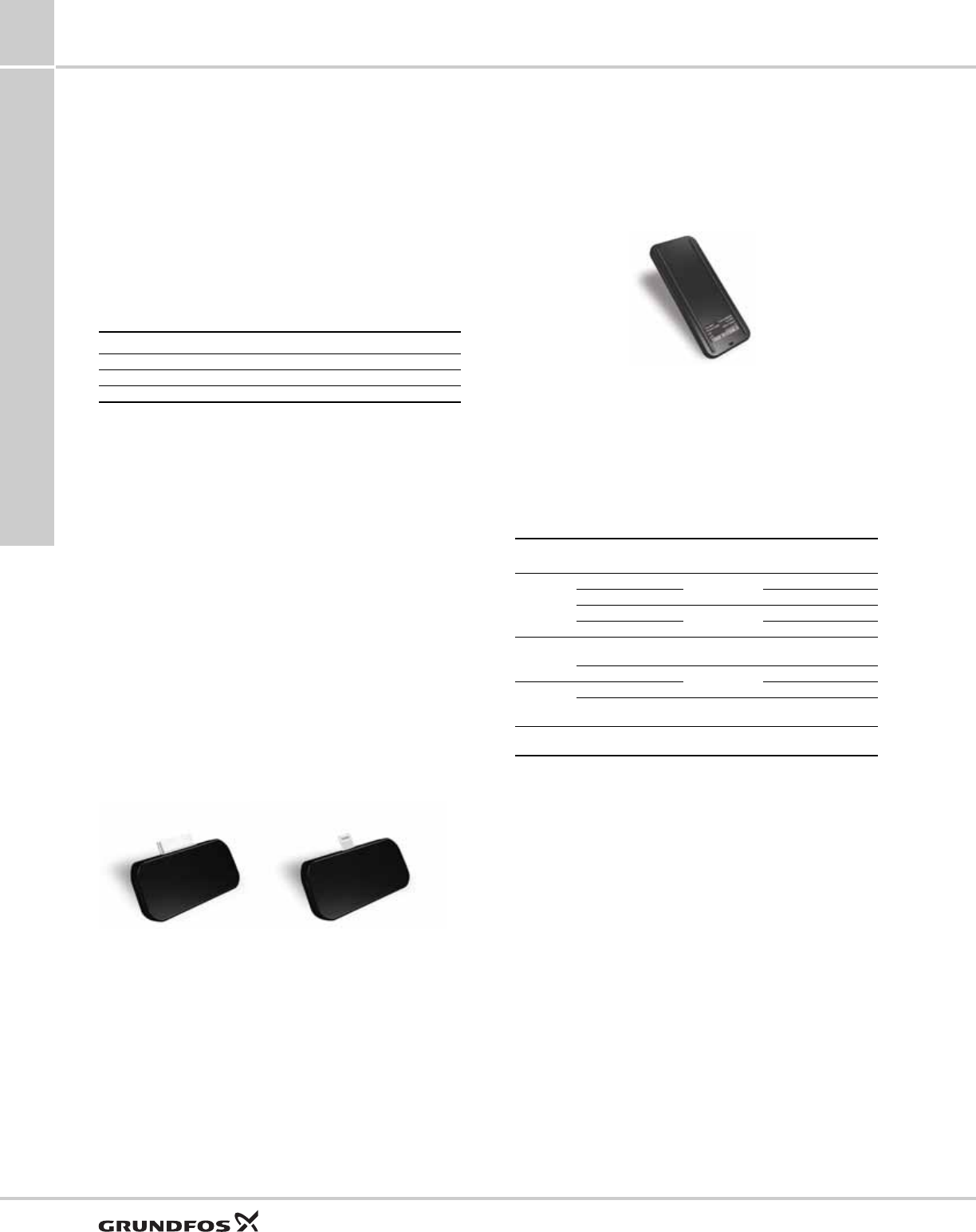
Accessories
MAGNA3
11
58
Grundfos GO Remote
The pump is designed for wireless communication with
the Grundfos GO Remote app which communicates
with the pump via radio communication.
Note: The radio communication between the pump
and the Grundfos GO Remote is encrypted to protect
against misuse.
The Grundfos GO Remote app is available from Apple
App Store and Android market.
The Grundfos GO Remote app must be used in
conjunction with one of the following Mobile Interface
devices:
The Grundfos GO Remote concept replaces the
Grundfos R100 remote control. This means that all
products supported by the R100 are supported by the
Grundfos GO Remote.
For function and connection to the pump, see separate
installation and operating instructions for the desired
type of Grundfos GO Remote setup.
Mobile interface
The available mobile interface devices are described
in the following.
MI 202 and MI 204
The MI 202 and MI 204 are add-on modules with
built-in infrared and radio communication. The MI 202
can be used in conjunction with Apple devices with
30-pin connector (iPhone 4, 4S and iPod touch 4G).
The MI 204 can be used in conjunction with Apple
devices with lightning connector (iPhone 5, 5C, 5S and
iPod touch 5G).
Fig. 59 MI 202 and MI 204
Supplied with the product:
• Grundfos MI 202 or 204
•sleeve
• quick guide
• charger cable.
MI 301
The MI 301 is a module with built-in infrared and radio
communication. The MI 301 must be used in
conjunction with an Android or iOS-based Smartphone
with a Bluetooth connection. The MI 301 has a
rechargeable Li-ion battery that must be charged
separately.
Fig. 60 MI 301
Supplied with the product:
• Grundfos MI 301
• sleeve
• battery charger
• quick guide.
Supported units
Note: Similar Android and iOS-based devices may
work as well, but are not supported by Grundfos.
Mobile interface Product number
Grundfos MI 202 98046376
Grundfos MI 204 98424092
Grundfos MI 301 98046408
TM05 3887 1612 - TM05 7704 1513
MI 202 MI 204
TM05 3887 1612
Make Model Operating
system MI
202 MI
204 MI
301
Apple
iPod touch 4G iOS 5.0 or
later
●-●
iPhone 4, 4S ●-●
iPod touch 5G iOS 6.0 or
later
-●●
iPhone 5, 5C, 5S - ●●
HTC Desire S Android 2.3.3
or later --●
Sensation Android 2.3.4
or later
--●
Samsung
Galaxy S II - - ●
Galaxy Nexus Android 4.0 or
later --●
LG Google Nexus 4 Android 4.2 or
later --●
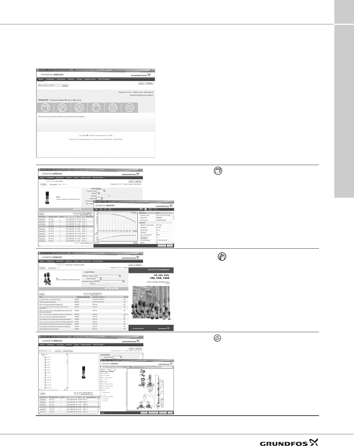
Further product information
MAGNA3 12
59
12. Further product information
WebCAPS
WebCAPS is a Web-based Computer Aided Product
Selection program available on www.grundfos.us.
WebCAPS contains detailed information on more than
220,000 Grundfos products in more than
30 languages.
Information in WebCAPS is divided into six sections:
• catalog
• literature
• service
• sizing
• replacement
• cad drawings.
Catalog
Based on fields of application and pump types, this section
contains the following:
• technical data
• curves (QH, Eff, P1, P2, etc.) which can be adapted to the
density and viscosity of the pumped liquid and show the
number of pumps in operation
• product photos
• dimensional drawings
• wiring diagrams
• quotation texts, etc.
Literature
This section contains all the latest documents of a given pump,
such as
• data booklets
• installation and operating instructions
• service documentation, such as service kit catalog and service
kit instructions
• quick guides
• product brochures.
Service
This section contains an easy-to-use interactive service catalog.
Here you can find and identify service parts of both existing and
discontinued Grundfos pumps.
Furthermore, the section contains service videos showing you
how to replace service parts.
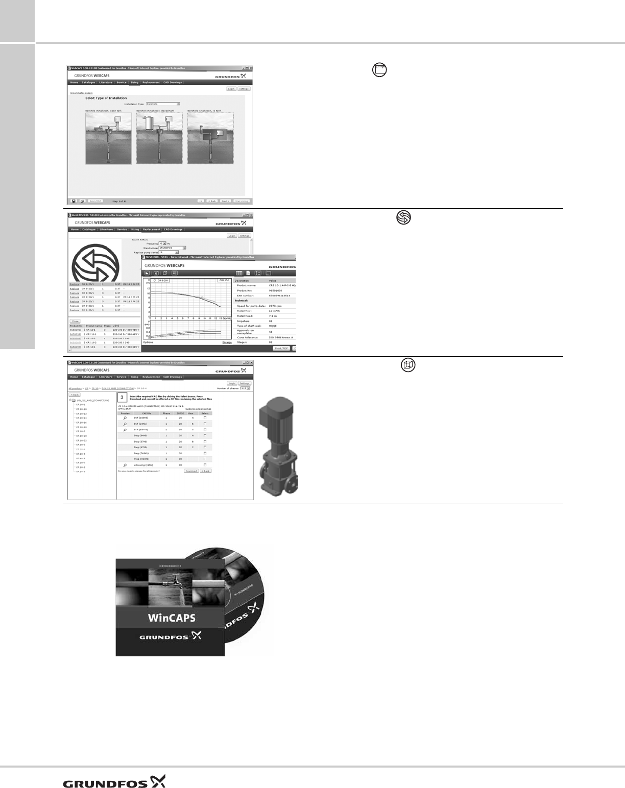
Further product information
MAGNA3
12
60
WinCAPS
Fig. 61 WinCAPS DVD
Sizing
This section is based on different fields of application and
installation examples and gives easy step-by-step instructions in
how to size a product:
• Select the most suitable and efficient pump for your
installation.
• Carry out advanced calculations based on energy,
consumption, payback periods, load profiles, life cycle costs,
etc.
• Analyze your selected pump via the built-in life cycle cost tool.
• Determine the flow velocity in wastewater applications, etc.
Replacement
In this section you find a guide to selecting and comparing
replacement data of an installed pump in order to replace the
pump with a more efficient Grundfos pump.
The section contains replacement data of a wide range of pumps
produced by other manufacturers than Grundfos.
Based on an easy step-by-step guide, you can compare
Grundfos pumps with the one you have installed on your site.
When you have specified the installed pump, the guide will
suggest a number of Grundfos pumps which can improve both
comfort and efficiency.
CAD drawings
In this section, it is possible to download 2-dimensional (2D) and
3-dimensional (3D) CAD drawings of most Grundfos pumps.
These formats are available in WebCAPS:
2-dimensional drawings:
• .dxf, wireframe drawings
• .dwg, wireframe drawings.
3-dimensional drawings:
• .dwg, wireframe drawings (without surfaces)
• .stp, solid drawings (with surfaces)
• .eprt, E-drawings.
WinCAPS is a Windows-based Computer Aided
Product Selection program containing detailed
information on more than 220,000 Grundfos products
in more than 30 languages.
The program contains the same features and
functions as WebCAPS, but is an ideal solution if no
internet connection is available.
WinCAPS is available on DVD and updated once a
year.
01

Further product information
MAGNA3 12
61
Grundfos GO
Mobile solution for professionals on the GO!
Grundfos GO is the mobile tool box for professional users on the go. It is the most comprehensive platform for mobile
pump control and pump selection including sizing, replacement and documentation. It offers intuitive, handheld
assistance and access to Grundfos online tools, and it saves valuable time for reporting and data collection.
GET IT ON
Subject to alterations.

62

63

The name Grundfos, the Grundfos logo, and be think innovate are registered trademarks owned by Grundfos Holding A/S or Grundfos A/S, Denmark. All rights reserved worldwide. © Copyright Grundfos Holding A/S
98439208 0414
ECM: 1131616
Grundfos Kansas City
17100 West 118th Terrace
Olathe, Kansas 66061
Phone: 913-227-3400
Fax: 913-227-3500
www.grundfos.us
Grundfos Canada
2941 Brighton Road
Oakville, Ontario L6H 6C9 Canada
Phone: +1-905-829-9533
Fax: +1-905-829-9512
www.grundfos.ca
Grundfos México
Boulevard TLC No. 15
Parque Industrial Stiva Aeropuerto
C.P. 66600 Apodaca, N.L. Mexico
Phone: 011-52-81-8144 4000
Fax: 011-52-81-8144 4010
www.grundfos.mx
