537341 3 Grundfos Magna3 Installation And Instructions User Manual
User Manual: Pump 537341 3 Grundfos Magna3 Installation And Instructions
Open the PDF directly: View PDF ![]() .
.
Page Count: 40
- English (US)
- 1. Limited warranty
- 2. Symbols used in this document
- 3. General information
- 4. Mechanical installation
- 5. Electrical installation
- 6. First start-up
- 7. Settings
- 8. Menu overview
- 9. Control panel
- 10. Menu structure
- 11. "Home" menu
- 12. "Status" menu
- 13. "Settings" menu
- 14. "Assist" menu
- 15. Selection of control mode
- 16. Fault finding
- 17. Sensor
- 18. Accessories
- 19. Technical data
- 20. Disposal
GRUNDFOS INSTRUCTIONS
MAGNA3
Installation and operating instructions

English (US)
2
English (US) Installation and operating instructions
Original installation and operating instructions.
CONTENTS
Page
1. Limited warranty
Products manufactured by GRUNDFOS PUMPS CORPORATION
(Grundfos) are warranted to the original user only to be free of
defects in material and workmanship for a period of 24 months
from date of installation, but not more than 30 months from date
of manufacture. Grundfos' liability under this warranty shall be
limited to repairing or replacing at Grundfos' option, without
charge, F.O.B. Grundfos' factory or authorized service station,
any product of Grundfos' manufacture. Grundfos will not be liable
for any costs of removal, installation, transportation, or any other
charges which may arise in connection with a warranty claim.
Products which are sold but not manufactured by Grundfos are
subject to the warranty provided by the manufacturer of said
products and not by Grundfos' warranty. Grundfos will not be
liable for damage or wear to products caused by abnormal
operating conditions, accident, abuse, misuse, unauthorized
alteration or repair, or if the product was not installed in
accordance with Grundfos' printed installation and operating
instructions.
To obtain service under this warranty, the defective product must
be returned to the distributor or dealer of Grundfos' products from
which it was purchased together with proof of purchase and
installation date, failure date, and supporting installation data.
Unless otherwise provided, the distributor or dealer will contact
Grundfos or an authorized service station for instructions. Any
defective product to be returned to Grundfos or a service station
must be sent freight prepaid; documentation supporting the war-
ranty claim and/or a Return Material Authorization must be
included if so instructed.
GRUNDFOS WILL NOT BE LIABLE FOR ANY
INCIDENTAL OR CONSEQUENTIAL DAMAGES, LOSSES, OR
EXPENSES ARISING FROM INSTALLATION, USE, OR ANY
OTHER CAUSES. THERE ARE NO EXPRESS OR IMPLIED
WARRANTIES, INCLUDING MERCHANTABILITY OR FITNESS
FOR A PARTICULAR PURPOSE, WHICH EXTEND BEYOND
THOSE WARRANTIES DESCRIBED OR REFERRED TO
ABOVE.
Some jurisdictions do not allow the exclusion or
limitation of incidental or consequential damages and some juris-
dictions do not allow limit actions on how long implied warranties
may last. Therefore, the above limitations or exclusions may not
1. Limited warranty 2
2. Symbols used in this document 3
3. General information 3
3.1 Applications 3
3.2 Pumped liquids 3
3.3 Operating conditions 4
3.4 Frost protection 4
3.5 Insulating shells 4
3.6 Non-return valve 4
3.7 Nameplate 5
3.8 Radio communication 6
3.9 Tools 6
4. Mechanical installation 6
4.1 Installing the pump 6
4.2 Positioning 7
4.3 Control box positions 7
4.4 Changing the control box position 8
5. Electrical installation 9
5.1 Supply voltage 9
5.2 Connection to the power supply 9
5.3 Connection diagram 11
5.4 Connection to external controllers 11
5.5 Input/output communication 11
5.6 Priority of settings 14
6. First start-up 15
7. Settings 16
7.1 Overview of settings 16
8. Menu overview 17
9. Control panel 18
10. Menu structure 18
11. "Home" menu 18
12. "Status" menu 18
13. "Settings" menu 19
13.1 Setpoint 19
13.2 Operating mode 19
13.3 Control mode 20
13.4 FLOWLIMIT 23
13.5 Automatic Night Setback 23
13.6 Relay outputs 23
13.7 Setpoint influence 24
13.8 Bus communication 25
13.9 General settings 25
14. "Assist" menu 27
14.1 Assisted pump setup 27
14.2 Setting of date and time 27
14.3 Multi-pump setup 27
14.4 Setup, analog input 27
14.5 Description of control mode 27
14.6 Assisted fault advice 27
14.7 Wireless GENIair 27
14.8 Multi-pump function 28
15. Selection of control mode 29
16. Fault finding 31
16.1 Grundfos Eye operating indications 31
16.2 Signalling communication with remote control 31
16.3 Fault finding 32
17. Sensor 33
17.1 Sensor specifications 33
18. Accessories 34
18.1 Grundfos GO Remote 34
18.2 Communication 34
18.3 Fitting the CIM module 35
19. Technical data 36
20. Disposal 36
Warning
Prior to installation, read these installation and
operating instructions. Installation and operation
must comply with local regulations and accepted
codes of good practice.
Warning
The use of this product requires experience with
and knowledge of the product.
Persons with reduced physical, sensory or
mental capabilities must not use this product,
unless they are under supervision or have been
instructed in the use of the product by a person
responsible for their safety.
Children must not use or play with this product.
3
English (US)
apply to you. This warranty gives you specific legal rights and you
may also have other rights which vary from jurisdiction to jurisdic-
tion.
2. Symbols used in this document
3. General information
The Grundfos MAGNA3 is a complete range of circulator pumps
with integrated controller enabling adjustment of pump
performance to the actual system requirements. In many
systems, this will reduce the power consumption considerably,
reduce noise from thermostatic radiator valves and similar fittings
and improve the control of the system.
The desired head can be set on the pump control panel.
3.1 Applications
The Grundfos MAGNA3 is designed for circulating liquids in the
following systems:
• heating systems
• domestic hot-water systems
• air-conditioning and cooling systems.
The pump can also be used in the following systems:
• ground source heat pump systems
• solar-heating systems.
3.2 Pumped liquids
The pump is suitable for thin, clean, non-aggressive and
non-explosive liquids, not containing solid particles or fibers that
may attack the pump mechanically or chemically.
In heating systems, the water should meet the requirements of
accepted standards on water quality in heating systems.
In domestic hot-water systems, we recommend to use MAGNA3
pumps only for water with a degree of hardness lower than
approx. 14 °dH.
In domestic hot-water systems, we recommend to keep the liquid
temperature below 150 °F (+65 °C) to eliminate the risk of lime
precipitation.
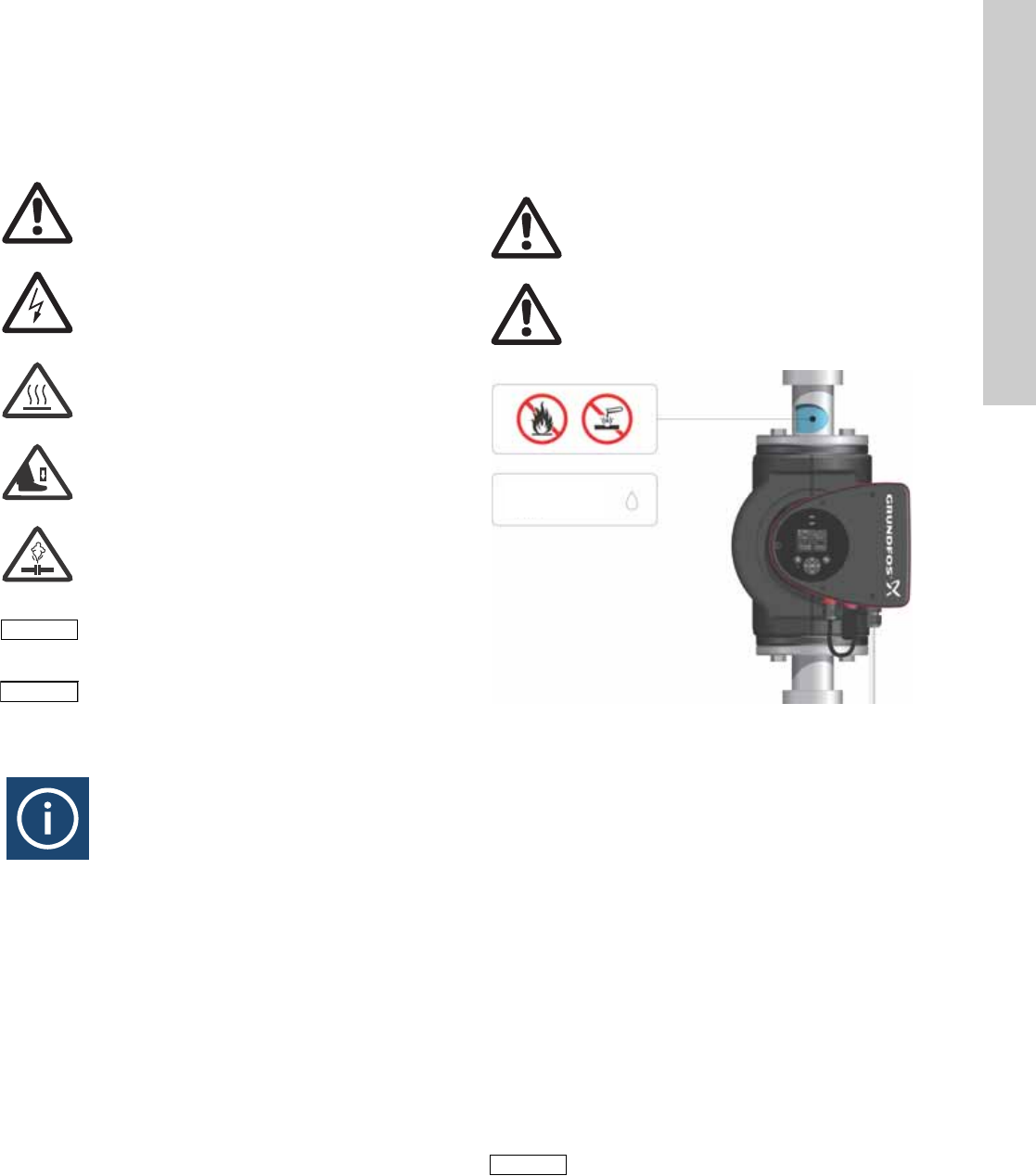
Fig. 1 Pumped liquids
3.2.1 Glycol
The pump can be used for pumping water/ethylene glycol
mixtures up to 50 %.
Maximum viscosity: 50 cSt ~ 50 % water / 50 % ethylene glycol
mixture at +14 °F (-10 °C).
The pump has a power-limiting function that protects against
overload.
The pumping of glycol mixtures will affect the max. curve and
reduce the performance, depending on the water/ethylene glycol
mixture and the liquid temperature.
To prevent the ethylene glycol mixture from degrading, avoid
temperatures exceeding the rated liquid temperature and
minimize the operating time at high temperatures.
It is important to clean and flush the system before the ethylene
glycol mixture is added.
To prevent corrosion or lime precipitation, check and maintain the
ethylene glycol mixture regularly. If further dilution of the supplied
ethylene glycol is required, follow the glycol supplier's
instructions.
Warning
If these safety instructions are not observed,
it may result in personal injury.
Warning
If these instructions are not observed, it may lead
to electric shock with consequent risk of serious
personal injury or death.
Warning
The surface of the product may be so hot that it
may cause burns or personal injury.
Warning
Risk of dropping objects which may cause
personal injury.
Warning
Escaping vapor involves the risk of personal
injury.
Caution
If these safety instructions are not observed,
it may result in malfunction or damage to the
equipment.
Note
Note
Notes or instructions that make the job easier
and ensure safe operation.
Warning
Do not use the pump for flammable liquids, such
as diesel oil and gasoline.
Warning
Do not use the pump for aggressive liquids, such
as acids and sea water.
TM05 2857 0612
Note
Note
Additives with a density and/or kinematic
viscosity higher than those/that of water will
reduce the hydraulic performance.
Max. 95 % RH
Enclosure Type 2
English (US)
4
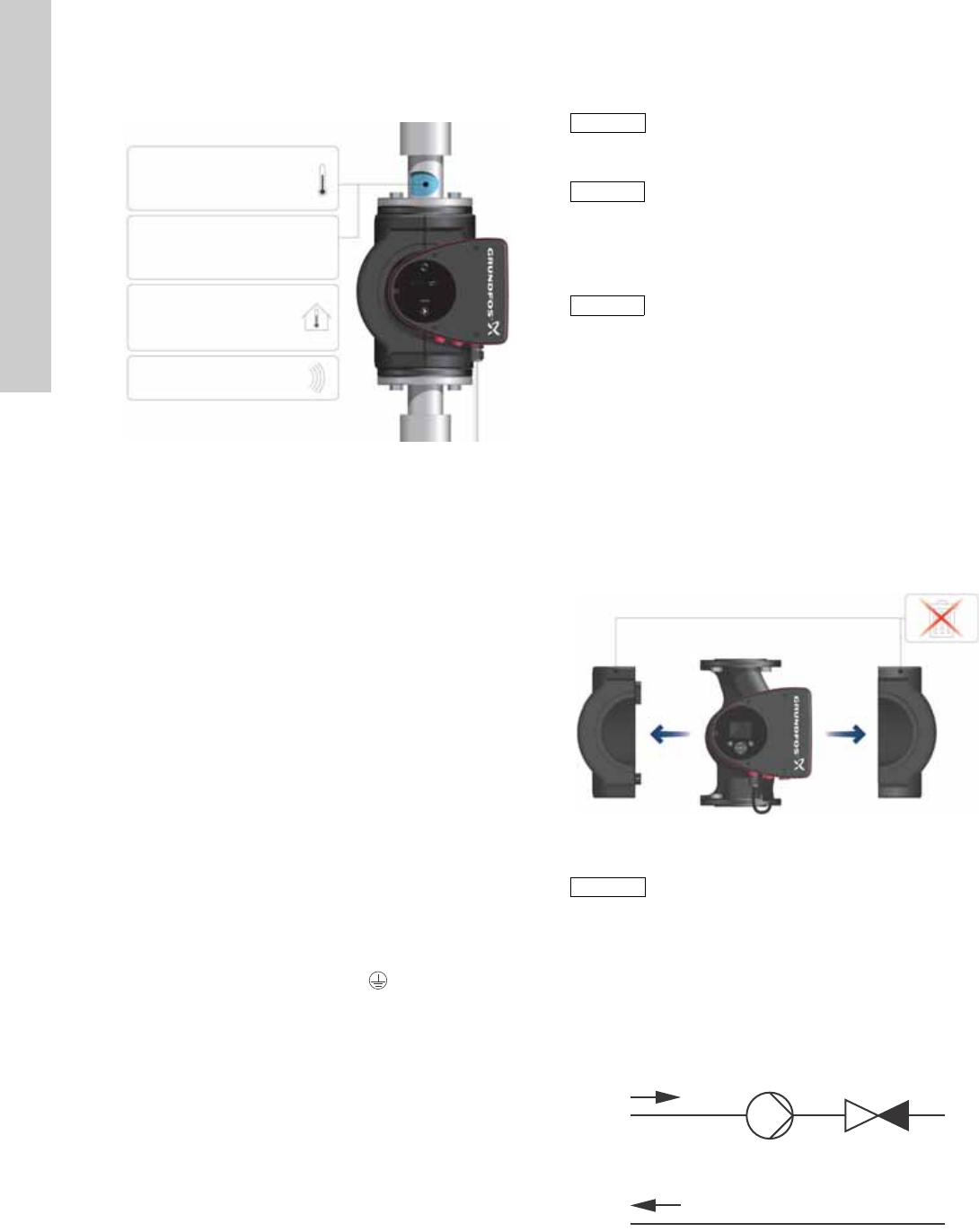
3.3 Operating conditions
Fig. 2 Operating conditions
3.3.1 Liquid temperature
See fig. 2, pos. 1.
Continuously: +14 °F to +230 °F (-10 °C to +110 °C).
Domestic hot-water systems:
• Up to +150 °F (+65 °C).
3.3.2 System pressure
See fig. 2, pos. 2.
The maximum permissible system pressure is stated on the pump
nameplate.
3.3.3 Ambient temperature
See fig. 2, pos. 3.
+32 °F to +104 °F (0 °C to +40 °C).
The control box is air-cooled. Therefore, it is important that the
maximum permissible ambient temperature is not exceeded
during operation.
During transport: -40 °F to +158 °F (-40 °C to +70 °C).
3.3.4 Sound pressure level
See fig. 2, pos. 4.
The sound pressure level of the pump is lower than 43 dB(A).
3.3.5 Approvals
• Conforms to ANSI/UL Standard 778.
• Certified to CAN/CSA Standard C22.2 No. 108.
• The protective earth (ground) symbol identifies any
terminal which is intended for connection to an external
conductor for protection against electrical shock in case of a
fault, or the terminal of a protective earth (ground) electrode.
3.4 Frost protection
3.5 Insulating shells
Insulating shells are available for single-head pumps only.
The heat loss from the pump and pipework can be reduced by
insulating the pump housing and the pipework. See fig. 3 and
fig. 10.
• Insulating shells for pumps in heating systems are supplied
with the pump; see fig. 3.
• For pumps in air-conditioning and cooling systems
(down to +14 ° (-10 °C)) it is required to apply a silicon sealant
to the internal contours of the shell in order to eliminate any air
gaps and prevent condensation between the insulation shell
and pump housing. Alternatively, the pump can also be
insulated manually in accordance with standard insulating
requirements for heating and cooling systems (fig. 10).
The fitting of insulating shells will increase the pump dimensions.
Fig. 3 Fitting insulating shells to the pump
3.6 Non-return valve
If a non-return valve is fitted in the pipe system (fig. 4), it must be
ensured that the set minimum discharge pressure of the pump is
always higher than the closing pressure of the valve. This is
especially important in proportional-pressure control mode
(reduced head at low flow). The closing pressure of a single
non-return valve is accounted for in the pump settings as the
minimum head delivered is 5 ft (1.5 m).
Fig. 4 Non-return valve
TM05 7662 1413
Min./Max.
+14 °F – 230 °F
(-10 °C – +110 °C)
175 psi (12 bar)
1
2
3
4
+32 to +104 °F
(0 to +40 °C)
<43 dB(A)
Caution
If the pump is not used during periods of frost,
necessary steps must be taken to prevent frost
bursts.
Note
Note
Additives with a density and/or kinematic
viscosity higher than those/that of water will
reduce the hydraulic performance.
Note
Note
Limit the heat loss from the pump housing and
pipework.
TM05 2859 0612
Caution
Do not insulate the control box or cover the
control panel.
TM05 3055 0912
5
English (US)
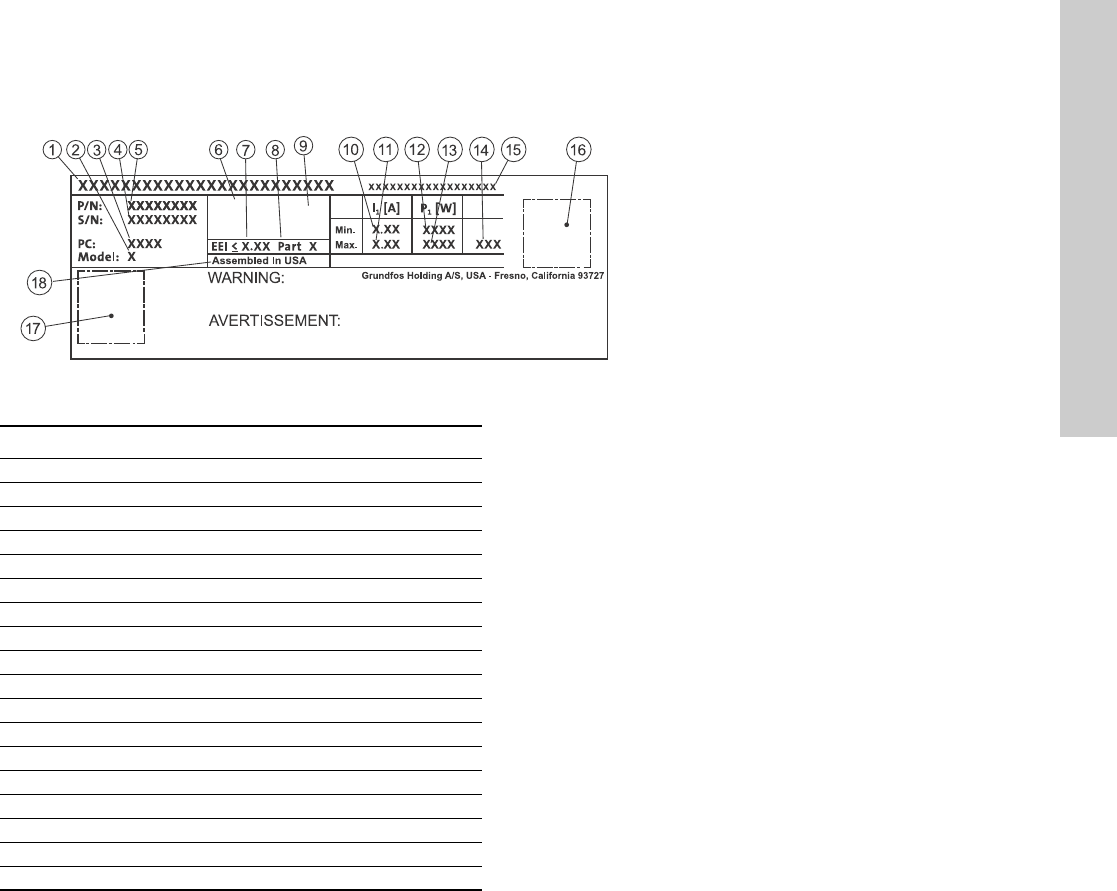
3.7 Nameplate
The pump nameplate provides the following information:
Fig. 5 Example of nameplate
TM05 6381 4612
RISQUE DE CHOC ELECTRIQUE. HORS DES EQUIPEMENT AVANT ENLEVEMENT DE LA COUVERTURE ET D’ENTRENTIEN. POUR
LE RECCORDEMENT D’ALIMENTATION, EMPLOYEZ DES FILS QUI RESISTENT AU MOINS A 90 °C UTILISEZ UNIQUEMENT DES
CONDUCTEURS DE CUIVRE. POUR RE’DUIRE LES RISQUES DE CHOC E’LECTRIQUE, CONSULTES LE MANUEL D’INSTRUCTIONS
POUR UNE INSTALLATION CORRECTE. EMPLOYER UNIQUEMENT A L’INTERIEUR.
TYPE 2
BOITIER DE TYPE 2
THERMALLY PROTECTED
Nonsubmersible Pump
RISK OF ELECTRIC SHOCK. DE-ENERGIZE EQUIPMENT BEFORE REMOVAL OF COVER & SERVICING. FOR SUPPLY
CONNECTION USE COPPER WIRE SUITABLE FOR 90 °C OR EQUIVALENT. THIS PUMP HAS NOT BEEN INVESTIGATED FOR USE
IN SWIMMING POOL OR MARINE AREAS. TO REDUCE THE RISK OF ELECTRIC SHOCK, SEE INSTRUCTION MANUAL FOR
PROPER INSTALLATION; ACCEPTABLE FOR INDOOR USE ONLY.
PSI
For use with maximum 230° F water
Contains FCC ID: OG3-RADIOM01-2G4
Pos. Description
1 Product name
2 Model
3 Production code (year and week)
4 Serial number
5 Product number
6 Enclosure type
7 Energy Efficiency Index (EEI)
8 Part (according to EEI)
9TF-class
10 Minimum current [A]
11 Maximum current [A]
12 Minimum power [W]
13 Maximum power [W]
14 Maximum pressure
15 Voltage [V] and frequency [Hz]
16 QR (Quick Response) code
17 Approvals (nameplate)
18 Assembled in USA
English (US)
6
3.8 Radio communication
The wireless radio in this product is class B.
Intended use
This product incorporates a radio for remote control.
The product can communicate with the Grundfos Go Remote and
with other MAGNA3 pumps of the same type via the built-in radio.
Only Grundfos-approved external antennae may be connected to
this product, and only by a Grundfos-approved installer.
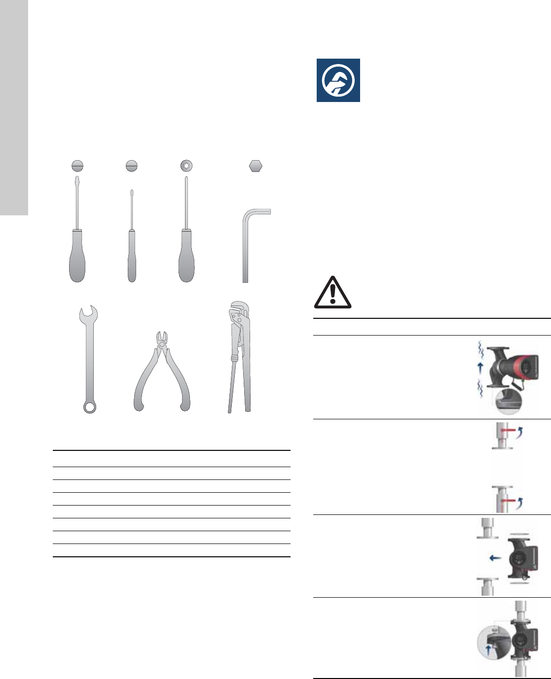
3.9 Tools
Fig. 6 Recommended tools
4. Mechanical installation
4.1 Installing the pump
The MAGNA3 is designed for indoor installation.
The pump must be installed in such a way that it is not stressed
by the pipework.
The pump may be suspended direct in the pipes, provided that
the pipework can support the pump.
Twin-head pumps are prepared for installation on a mounting
bracket or base plate.
To ensure adequate cooling of motor and electronics, the
following must be observed:
• Position the pump in such a way that sufficient cooling is
ensured.
• The temperature of the ambient air must not exceed
+104 °F (+40 °C).
TM05 6472 4712
Pos. Tool Size
1 Screwdriver, straight slot 1.2 x 8.0 mm
2 Screwdriver, straight slot 0.6 x 3.5 mm
3 Screwdriver, torx bit TX20
4 Hexagon key 5.0 mm
5 Open end wrench Depending on PN size
6 Wire cutter
7Pipe wrench
1.2 x 8.0 TX200.6 x 3.5 5.0
1234
567
Warning
Observe local regulations setting limits for
manual lifting or handling.
Step Action Illustration
1
Arrows on the pump housing
indicate the liquid flow direction
through the pump. The liquid
flow direction can be horizontal
or vertical, depending on the
control box position.
TM05 2862 0612
2
Close the isolating valves and
make sure that the system is not
pressurized during the
installation of the pump.
TM05 2863 0612
3Mount the pump with gaskets in
the pipework.
TM05 2864 0612
4
Fit bolts and nuts. Use the right
size of bolts according to system
pressure.
TM05 2865 0612
7
English (US)
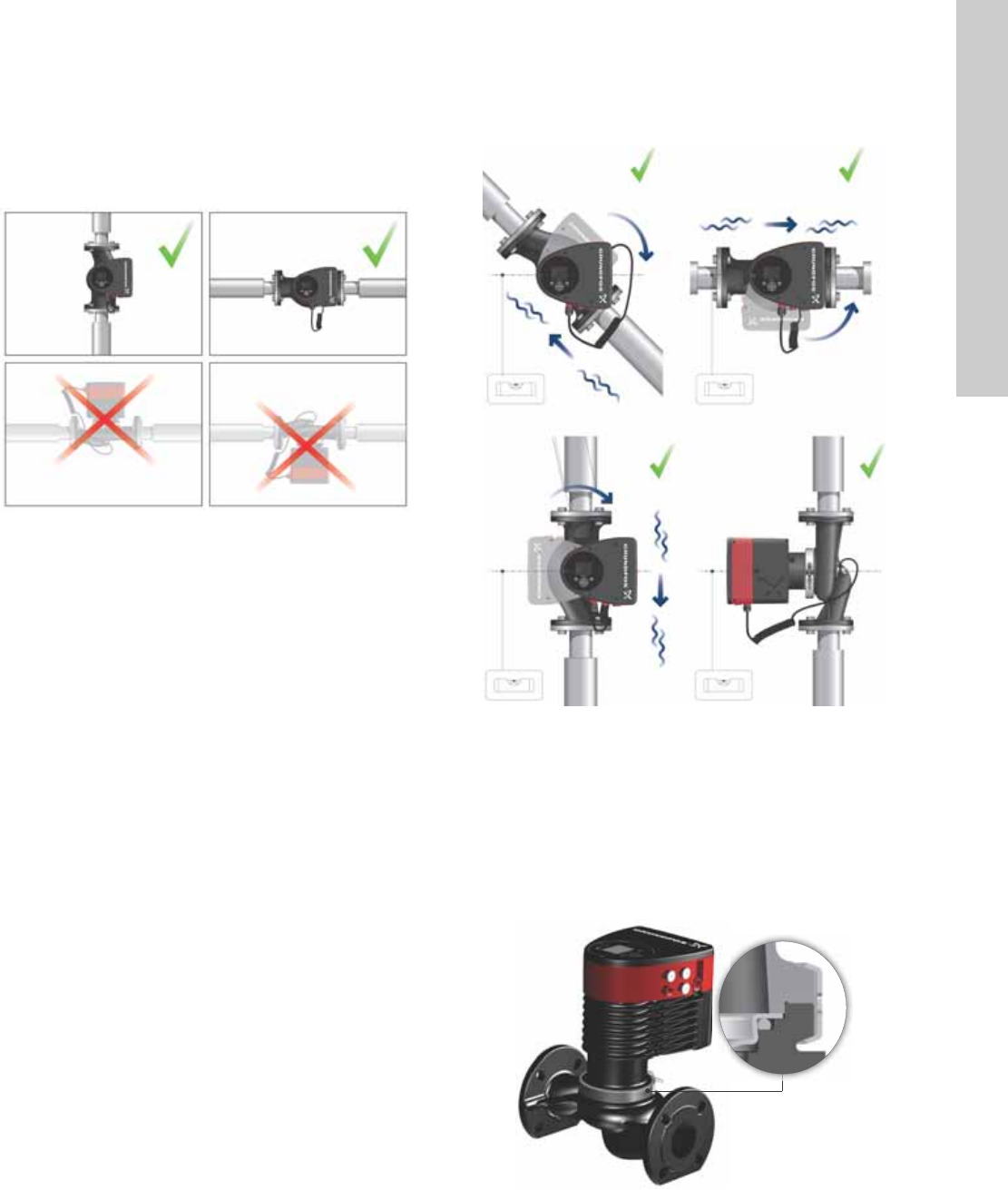
4.2 Positioning
Always install the pump with horizontal motor shaft.
• Pump installed correctly in a vertical pipe. See fig. 7, pos. A.
• Pump installed correctly in a horizontal pipe. See fig. 7, pos. B.
• Do not install the pump with vertical motor shaft. See fig. 7,
pos. C and D.
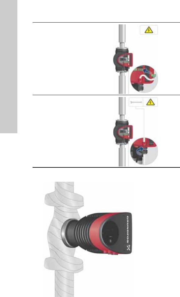
Fig. 7 Pump installed with horizontal motor shaft
4.3 Control box positions
To ensure adequate cooling, the control box must be in horizontal
position with the Grundfos logo in vertical position. See fig. 8.
Fig. 8 Pump with control box in horizontal position
If the pump head is removed before the pump is installed in the
pipework, pay special attention when fitting the pump head to the
pump housing:
1. Gently lower the pump head with rotor shaft and impeller into
the pump housing.
2. Make sure that the contact face of the pump housing and that
of the pump head are in contact before the clamp is tightened.
See fig. 9.
Fig. 9 Fitting the pump head to the pump housing
TM05 2866 0712
AB
CD
TM05 2915 0612TM05 5837 4112
English (US)
8
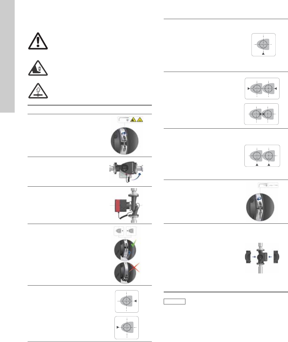
4.4 Changing the control box position
Warning
The warning symbol on the clamp holding the
pump head and pump housing together indicates
that there is a risk of personal injury. See specific
warnings below.
Warning
When loosening the clamp, do not drop the pump
head.
Warning
Risk of escaping vapor.
Step Action Illustration
1
Loosen the screw in the clamp
holding the pump head and
pump housing together.
Warning: If the screw is
loosened too much, the pump
head will be completely
disconnected from the pump
housing.
TM05 2867 0612
2
Carefully rotate the pump head
to the desired position.
If the pump head is stuck,
loosen it with a light blow of a
rubber mallet.
TM05 2868 0612
3
Position the control box in
horizontal position so that the
Grundfos logo is in vertical
position. The motor shaft must
be horizontal.
TM05 2869 0612
4
Due to the drain hole in the
stator housing, position the gap
of the clamp as shown in step
4a, 4b, 4c or 4d.
TM05 2870 0612
4a
Single-head pump.
Position the clamp so that the
gap points towards the arrow.
It can be in position 3 or
9 o’clock.
TM05 2918 0612 - TM05 2871 0612
4b
Single-head pump.
Note: The gap of the clamp can
also be in position 6 o’clock for
the following pump sizes:
• MAGNA3 65-XX
• MAGNA3 80-XX
• MAGNA3 100-XX.
TM05 2899 1912
4c
Twin-head pump.
Position the clamps so that the
gaps point towards the arrows.
They can be in position
3 or 9 o’clock.
TM05 2917 0612 - TM05 2873 0612
4d
Twin-head pump.
Note: The gap of the clamp can
also be in position 6 o’clock for
the following pump sizes:
• MAGNA3 65-XX
• MAGNA3 80-XX
• MAGNA3 100-XX.
TM05 2897 1912
6
Fit and tighten the screw
holding the clamp to minimum
6 ± 0.7 ft-lbs
(8 ± 1 Nm).
TM05 2872 0612
7
Fit the insulating shells.
Note: For air conditioning and
cooling systems a silicone
sealant must be applied inside
the insulation shell to eliminate
all air gaps and prevent
condensation between the
pump housing and insulation
shell. Alternatively, the pump
may be insulated manually in
accordance with standard
insulation practices for cooling
applications.
TM05 2874 0412
Caution
If insulating the pump manually, do not insulate
the control box or cover the control panel.
9
English (US)
5. Electrical installation
Carry out the electrical connection and protection according to
local regulations.
Check that the supply voltage and frequency correspond to the
values stated on the nameplate.
• If rigid conduit is to be used, the hub must be connected to the
conduit system before it is connected to the terminal box of the
pump.
• The pump must be connected to an external mains switch.
• The pump requires no external motor protection.
• The motor incorporates thermal protection against slow
overloading and blocking.
• When switched on via the power supply, the pump will start
pumping after approx. 5 seconds.
5.1 Supply voltage
1 x 115 V ± 10 %, 50/60 Hz, PE.
1 x 208-230 V ± 10 %, 50/60 Hz, PE.
See Pump Nameplate for rated supply voltage
The voltage tolerances are intended for mains voltage variations.
They should not be used for running pumps at other voltages than
those stated on the nameplate.
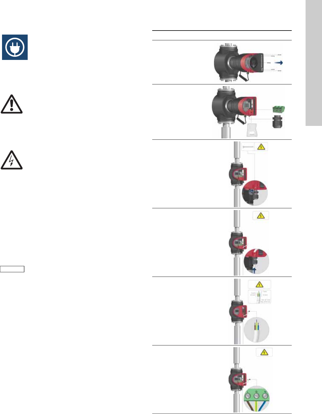
5.2 Connection to the power supply
Warning
Never make any connections in the pump control
box unless the electricity supply has been
switched off for at least 5 minutes.
Warning
The pump must be connected to an external
mains switch with a contact separation of at least
1/8 inch (3 mm) in each pole.
The ground terminal of the pump must be earth
ground. Grounding or neutralization can be used
for protection against indirect contact.
If the pump is connected to an electric
installation where a Ground Fault Circuit
Interrupt (GFCI) is used as additional protection,
this circuit breaker must trip out when ground
fault currents with DC content (pulsating DC)
occur.
Note
Note
The number of starts and stops via the power
supply must not exceed four times per hour.
Step Action Illustration
1
Remove the front
cover from the
control box.
TM05 2875 0612
2
Locate the power
supply plug and
conduit adapter in
the box supplied
with the pump.
TM05 2876 0612
3
Connect the
conduit adapter to
the control box.
TM05 2877 0612
4
Pull the power
supply cable
through the
conduit adapter
and thread on
conduit.
TM05 2878 0612
5
Strip the cable
conductors as
illustrated.
TM05 5534 3812
6
Connect the cable
conductors to the
power supply plug.
L - L or L1
Ground - Ground
N - N or L2
TM05 2880 0612
English (US)
10
Fig. 10 Insulation of pump housing and pipework
7
Insert the power
supply plug into
the male plug in
the pump control
box.
TM05 2881 0612
8
Tighten the
conduit adapter.
Refit the front
cover.
TM05 2882 0612
TM05 5549 3812
11
English (US)
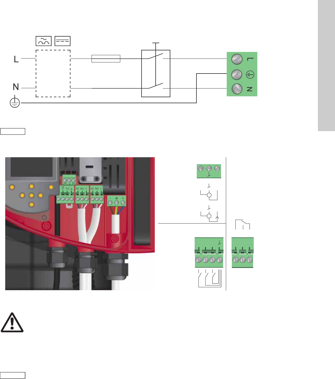
5.3 Connection diagram
Fig. 11 Example of typical connection, 1 x 230 V ± 10 %, 50/60 Hz
5.4 Connection to external controllers
Fig. 12 Connection diagram
Concerning demands on signal wires and signal transmitters,
see section 19. Technical data.
Use screened cables for external on/off switch, digital input,
sensor and setpoint signals.
5.5 Input/output communication
• Relay outputs
Alarm, ready and operating indication via signal relay.
• Digital input
– Start/Stop (S/S)
– Min. curve (MI)
– Max. curve (MA).
• Analog input
0-10 V or 4-20 mA control signal.
To be used for external control of the pump or as sensor input
for the control of the external setpoint.
The 24 V supply from pump to sensor is optional and is
normally used when an external supply is not available.
TM03 2397 0312
External switch
Fuse
(min. 10 A, time lag)
ELCB
Note
Note
All cables used must be connected in
accordance with local regulations.
TM05 2901 1912 - TM05 3343 1212
Max.
250 V AC
2 A AC1
Min.
5 V DC
20 mA
Max.
24 V DC
22 mA
0-10 V DC
4-20 mA
I
NC NO C
S/S
M
I
M
A
IN
24V
Vcc Signal
Vcc Signal
3
2
1
Warning
Wires connected to supply terminals, outputs
NC, NO, C and start/stop input must be separated
from each other and from the supply by
reinforced insulation.
Note
Note
All cables used must be heat-resistant up to
+185 °F (+85 °C).
English (US)
12
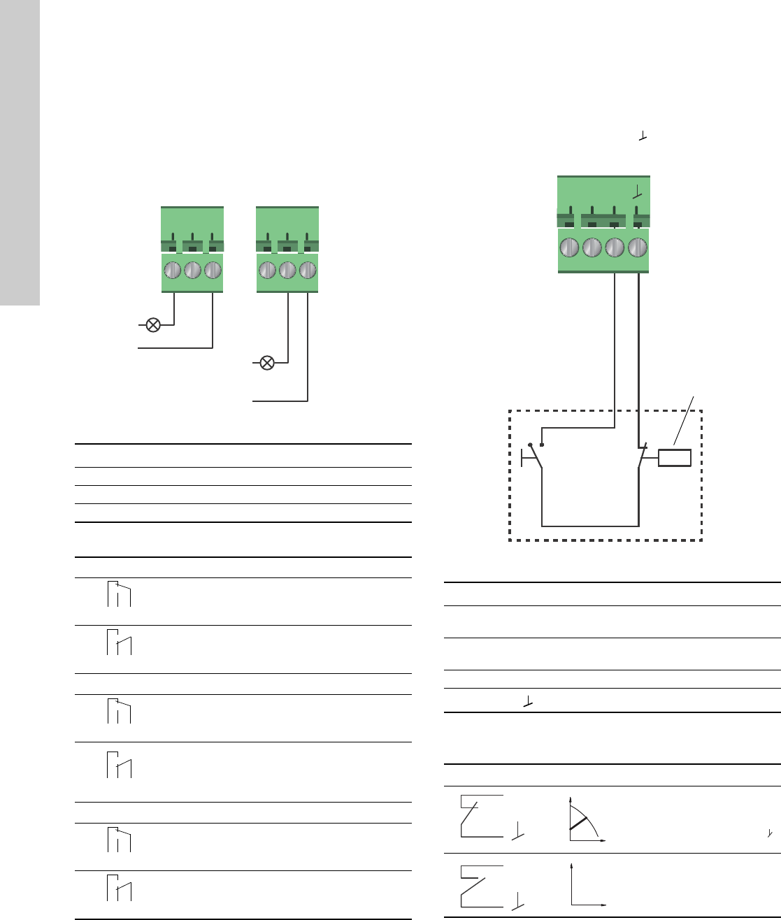
5.5.1 Relay outputs
See fig. 12, pos. 1.
The pump incorporates two signal relays with a potential-free
changeover contact for external fault indication.
The function of the signal relay can be set to "Alarm", "Ready" or
"Operation" on the pump control panel or with the Grundfos GO
Remote.
The relays can be used for outputs up to 250 V and 2 A.
Fig. 13 Relay output
The functions of the signal relays appear from the table below:
5.5.2 Digital inputs
See fig. 12, pos. 2.
The digital input can be used for external control of start/stop or
forced max. or min. curve.
If no external on/off switch is connected, the jumper between
terminals Start/Stop (S/S) and frame ( ) should be maintain ed.
This connection is the factory setting.
Fig. 14 Digital input
External start/stop
The pump can be started or stopped via the digital input.
TM05 3338 1212
Contact symbol Function
NC Normally closed
NO Normally open
C Common
Signal relay Alarm signal
Not activated:
• The power supply has been switched off.
• The pump has not registered a fault.
Activated:
• The pump has registered a fault.
Signal relay Ready signal
Not activated:
• The pump has registered a fault and is
unable to run.
Activated:
• The pump has been set to stop, but is ready
to run.
• The pump is running.
Signal relay Operating signal
Not activated:
• The pump is not running.
Activated:
• The pump is running.
NC NO C NC NO C
Alarm
Operation
Relay 1 Relay 2
132
NC NO C
132
NC NO C
12 3
NC NO C
132
NC NO C
132
NC NO C
12 3
NC NO C
132
NC NO C
132
NC NO C
12 3
NC NO C
TM05 3339 1212
Contact symbol Function
M
A
Max. curve
100 % speed
M
I
Min. curve
25 % speed
S/S Start/Stop
Frame connection
Start/stop
Normal duty
Note: Factory setting with
jumper between S/S and .
Stop
S/S
M
I
M
A
On/off timer
Start/stop
S/S
Q
H
S/S
Q
H
13
English (US)
External forced max. or min. curve
The pump can be forced to operate on the max. or min. curve via
the digital input.
Select the function of the digital input on the pump control panel
or with the Grundfos GO Remote.
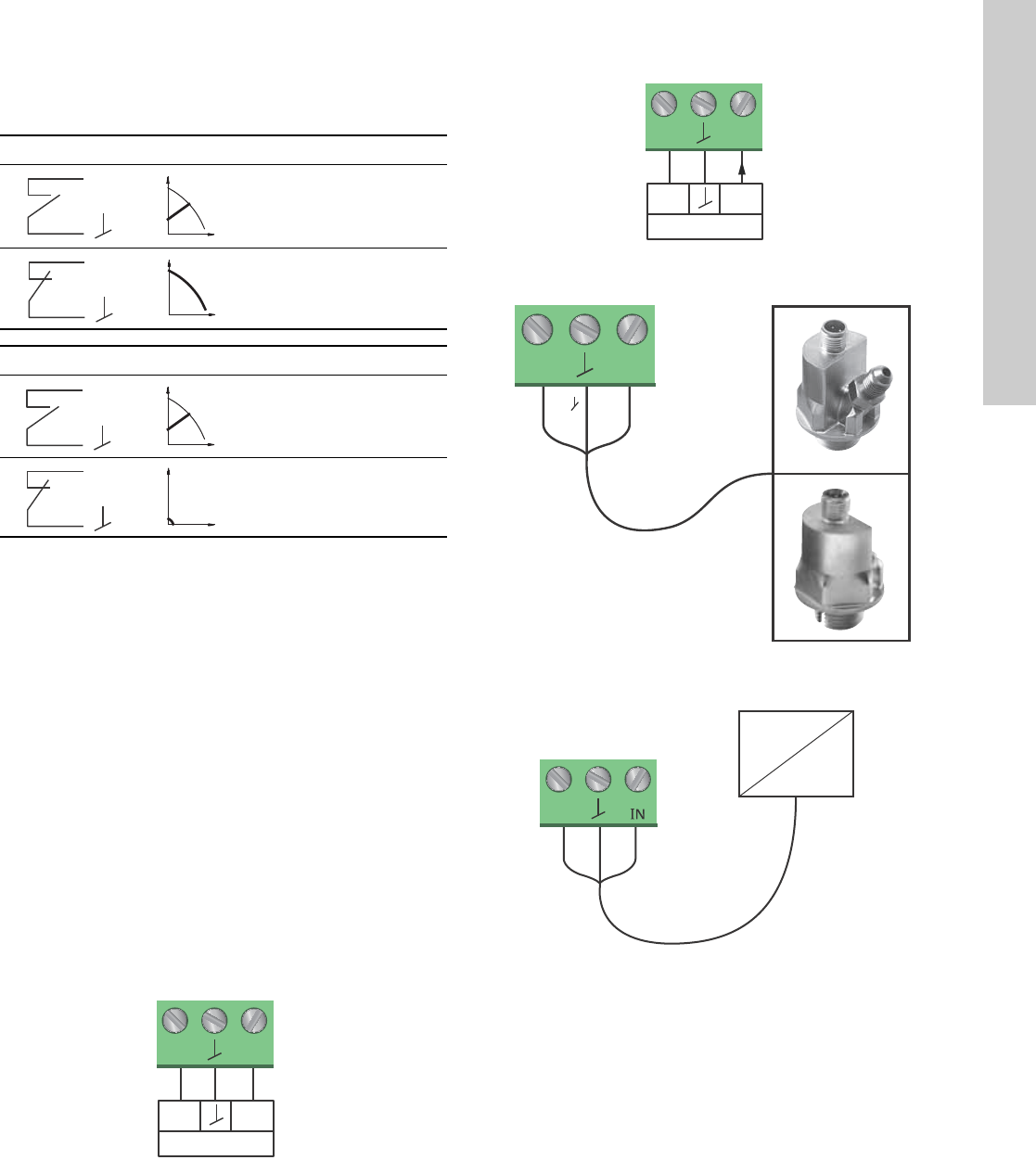
5.5.3 Analog input
See fig. 12, pos. 3.
The analog input can be used for the connection of an external
sensor for measuring temperature, pressure, flow or other
parameter. See fig. 17.
It is possible to use sensor types with 0-10 V or 4-20 mA signal.
The analog input can also be used for an external signal for the
control from a BMS system or similar control system. See fig. 18.
• When the input is used for the heat energy meter, a
temperature sensor must be installed in the return pipe.
• If the pump is installed in the return pipe of the system, the
sensor must be installed in the flow pipe.
• If the constant-temperature control mode has been enabled
and the pump is installed in the flow pipe of the system, the
sensor must be installed in the return pipe.
• If the pump is installed in the return pipe of the system, the
built-in temperature sensor can be used.
The selection of sensor type (0-10 V or 4-20 mA) can be changed
on the pump control panel or with the Grundfos GO Remote.
Fig. 15 Analog input for external sensor, 0-10 V
Fig. 16 Analog input for external sensor, 4-20 mA
Fig. 17 Examples of external sensors
Fig. 18 Examples of external signal for the control via
BMS/PLC
Max. curve
Normal duty
Max. curve
Min. curve
Normal duty
Min. curve
TM05 3221 0612
M
A
Q
H
M
A
Q
H
M
I
Q
H
M
I
Q
H
signal
sensor
Vcc
24V
I
N
signal
sensor
Vcc
24V
I
N
TM05 2948 0612TM05 2947 1212TM05 2888 0612
signal
sensor
Vcc
I
24V
I
N
24V
IN
Vcc Signal
24V
BMS
PLC

English (US)
14
5.6 Priority of settings
The external forced-control signals will influence the settings
available on the pump control panel or with the Grundfos GO
Remote. However, the pump can always be set to max. curve
duty or to stop on the pump control panel or with the
Grundfos GO Remote.
If two or more functions are enabled at the same time, the pump
will operate according to the setting with the highest priority.
The priority of the settings is as shown in the table below.
Example: If the pump has been forced to stop via an external
signal, the pump control panel or the Grundfos GO Remote can
only set the pump to max. curve.
As illustrated in the table, the pump does not react to external
signals (max. curve and min. curve) when it is controlled via bus.
For further details, please contact Grundfos.
Priority
Possible settings
Pump control
panel or
Grundfos GO
Remote
External
signals Bus signal
1 Stop
2 Max. curve
3Stop
4Stop
5Max. curve
6Min. curve
7Start
8Max. curve
9Min. curve
10 Min. curve
11 Start
15
English (US)
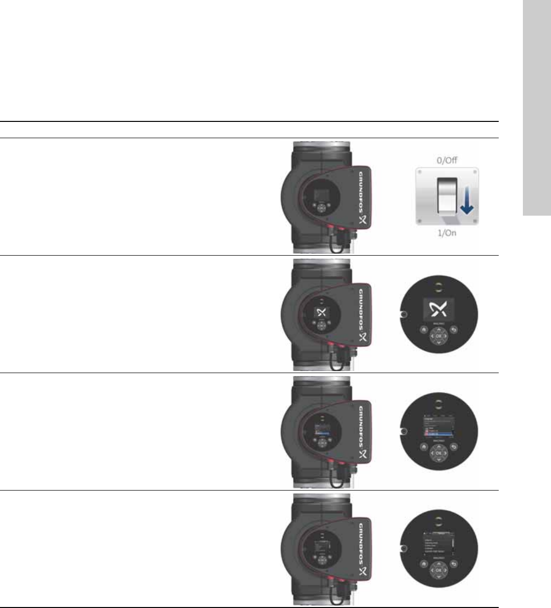
6. First start-up
Do not start the pump until the system has been filled with liquid
and vented. Furthermore, the required minimum inlet pressure
must be available at the pump inlet. See section 19. Technical
data.
The system cannot be vented through the pump. The pump is
self-venting.
Step Action Illustration
1
Switch on the power supply to the pump.
Note: When switched on, the pump will start in
AUTOADAPT after approx. 5 seconds.
TM05 2884 0612
2
Pump display at first start-up.
After a few seconds, the pump display will change to the
start-up guide.
TM05 2885 0612
3
The start-up guide will guide you through the general
settings of the pump, such as language, date and time.
If the buttons on the pump control panel are not touched
for 15 minutes, the display will go into sleep mode. When
a button is touched, the "Home" display will appear.
TM05 2886 0612
4
When the general settings have been made, select the
desired control mode or let the pump run in AUTOADAPT.
For additional settings, see section 7.
Settings
.
TM05 2887 0612

English (US)
16
7. Settings
7.1 Overview of settings
All settings can be made on the pump control panel or with the Grundfos GO Remote.
Menu Submenu Further information
Setpoint See section 13.1
Setpoint
.
Operating mode See section 13.2
Operating mode
.
•Normal
•Stop
•Min.
•Max.
Control mode See section 13.3
Control mode
.
•AUTO
ADAPT See section 13.3.1 AUTOADAPT.
•FLOW
ADAPT See section 13.3.2 FLOWADAPT.
•Prop. press. See section 13.3.3 Proportional pressure.
•Const. press. See section 13.3.4 Constant pressure.
•Const. temp. See section 13.3.5 Constant temperature.
• Differential temperature See section 13.3.6 Differential temperature.
•Constant curve See section 13.3.7 Constant curve.
FLOWLIMIT See section 13.4 FLOWLIMIT.
•Set FLOWLIMIT
Automatic Night Setback See section 13.5
Automatic Night Setback
.
•Not active
•Active
Relay outputs See section 13.6
Relay outputs
.
•Relay output 1
•Relay output 2
Setpoint influence See section 13.7
Setpoint influence
.
•External setpoint function See section 13.7.1
External setpoint function
.
•Temperature influence See section 13.7.2
Temperature influence
.
Bus communication See section 13.8
Bus communication
.
•Pump number See section 13.8.1
Pump number
.
General settings See section 13.9
General settings
.
•Language See section 13.9.1
Language
.
•Set date and time See section 13.9.2
Set date and time
.
•Units See section 13.9.3
Units
.
•Enable/disable settings See section 13.9.4
Enable/disable settings
.
•Delete history See section 13.9.5
Delete history
.
•Define Home display See section 13.9.6
Define Home display
.
•Display brightness See section 13.9.7
Display brightness
.
•Return to factory settings See section 13.9.8
Return to factory settings
.
•Run start-up guide See section 13.9.9
Run start-up guide
.

17
English (US)
8. Menu overview
Status Settings Assist
Operating status Setpoint Assisted pump setup
Operating mode, from Operating mode Setting of pump
Control mode Control mode Setting of date and time
Pump performance FLOWLIMIT Date format, date and time
Max. curve and duty point Enable FLOWLIMIT function Date only
Resulting setpoint Set FLOWLIMIT Time only
Liquid temperature Automatic Night Setback Multi-pump setup
Speed Relay outputs Setup, analog input
Operating hours Relay output 1 Description of control mode
Power and energy consumption Relay output 2 AUTOADAPT
Power consumption Not active FLOWADAPT
Energy consumption Ready Prop. press.
Warning and alarm Alarm Const. press.
Actual warning or alarm Operation Const. temp.
Warning log Setpoint influence Differential temperature
Warning log 1 to 5 External setpoint function Constant curve
Alarm log Temperature influence Assisted fault advice
Alarm log 1 to 5 Bus communication Blocked pump
Heat energy meter Pump number Pump communication fault
Heat power General settings Internal fault
Heat energy Language Internal sensor fault
Flow rate Set date and time Dry running
Volume Select date format Forced pumping
Hours counter Set date Undervoltage
Temperature 1 Select time format Overvoltage
Temperature 2 Set time External sensor fault
Differential temp. Units
Work log SI or US units
Operating hours Customized units
Trend data Pressure
Duty point over time Differential pressure
3D showing (Q, H, t) Head
3D showing (Q, T, t) Level
3D showing (Q, P, t) Flow rate
3D showing (T, P, t) Volume
Fitted modules Temperature
Date and time Differential temp.
Date Power
Time Energy
Pump identification Enable/disable settings
Multi-pump system Delete history
Operating status Delete work log
Operating mode, from Delete heat energy data
Control mode Delete energy consumption
System performance Define Home display
Duty point Select Home display type
Resulting setpoint List of data
System identification Graphical illustration
Power and energy consumption Define Home display contents
Power consumption List of data
Energy consumption Graphical illustration
Other pump 1, multi-pump sys. Display brightness
Brightness
Return to factory settings
Run start-up guide
English (US)
18
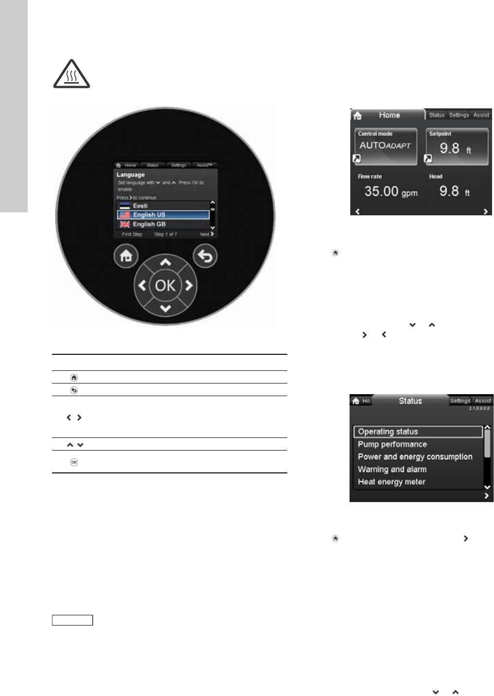
9. Control panel
Fig. 19 Control panel
10. Menu structure
The pump incorporates a start-up guide which is started at the
first start-up. After the start-up guide, the four main menus will
appear in the display. See section 6. First start-up.
1. Home
This menu shows up to four user-defined parameters with
shortcuts or a graphical illustration of a Q/H performance curve.
See section 11. "
Home
" menu.
2. Status
This menu shows the status of the pump and system as well as
warnings and alarms. See section 12. "
Status
" menu.
3. Settings
This menu gives access to all setting parameters. A detailed
setting of the pump can be made in this menu.
See section 13. "
Settings
" menu.
4. Assist
This menu enables assisted pump setup, provides a short
description of the control modes and offers fault advice.
See section 14. "
Assist
" menu.
11. "Home" menu
Navigation
Home
Press to go to the "Home" menu.
"Home" menu (factory setting)
• Shortcut to control mode settings
• Shortcut to setpoint settings
•Flow rate
•Head.
Navigate in the display with or and change between the two
shortcuts with or .
The "Home" display can be defined by the user.
See section 13.9.6
Define Home display
.
12. "Status" menu
Navigation
Home > Status
Press and go to the "Status" menu with .
"Status" menu
This menu offers the following status information:
•Operating status
•Pump performance
•Power and energy consumption
•Warning and alarm
•Heat energy meter
•Work log
•Fitted modules
•Date and time
•Pump identification
•Multi-pump system.
Navigate between submenus with or .
Warning
At high liquid temperatures, the pump housing
may be so hot that only the control panel should
be touched to avoid burns.
TM05 7642 1313
Button Function
Goes to the "Home" menu.
Returns to the previous action.
Navigates between main menus, displays and
digits.
When the menu is changed, the display will always
show the top display of the new menu.
Navigates between submenus.
Saves changed values, resets alarms and expands
the value field.
Note
Note
No settings can be made in this menu.
TM05 7929 1613
2.1.0.0.0.0 Status
19
English (US)
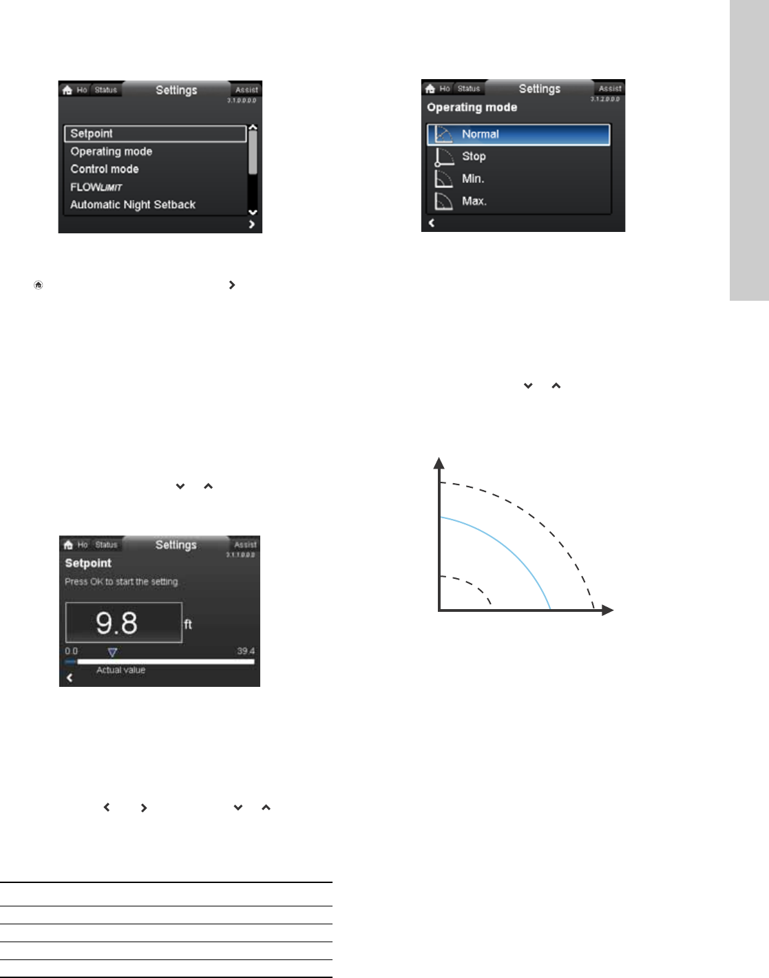
13. "Settings" menu
Navigation
Home > Settings
Press and go to the "Settings" menu with .
"Settings" menu
This menu offers the following setting options:
•Setpoint
•Operating mode
•Control mode
•FLOW
LIMIT
•Automatic Night Setback
•Relay outputs
•Setpoint influence
•Bus communication
•General settings.
Navigate between submenus with or .
13.1 Setpoint
Navigation
Home > Settings > Setpoint
Setpoint
Set the setpoint so that it matches the system.
Setting:
1. Press [OK] to start the setting.
2. Select digit with and and adjust with or .
3. Press [OK] to save.
A too high setting may result in noise in the system whereas a too
low setting may result in insufficient heating or cooling in the
system.
13.2 Operating mode
Navigation
Home > Settings > Operating mode
Operating mode
•Normal (control mode)
•Stop
•Min. (min. curve)
•Max. (max. curve).
Setting:
1. Select operating mode with or .
2. Press [OK] to save.
The pump can be set to operate according to the max. or min.
curve, like an uncontrolled pump. See fig. 20.
Fig. 20 Max. and min. curves
•Normal: The pump runs according to the selected control
mode.
•Stop: The pump stops.
•Min.: The min. curve mode can be used in periods in which a
minimum flow is required.
This operating mode is for instance suitable for manual night
setback if Automatic Night Setback is not desired.
•Max.: The max. curve mode can be used in periods in which a
maximum flow is required.
This operating mode is for instance suitable for hot-water
priority.
3.1.0.0.0.0 Settings
TM05 7925 1613
Control mode Measuring unit
Proportional pressure m, ft
Constant pressure m, ft
Constant temperature °C, °F, K
Constant curve %
3.1.2.0.0.0 Operating mode
TM05 2446 5111
H
Q
Max.
Min.
English (US)
20
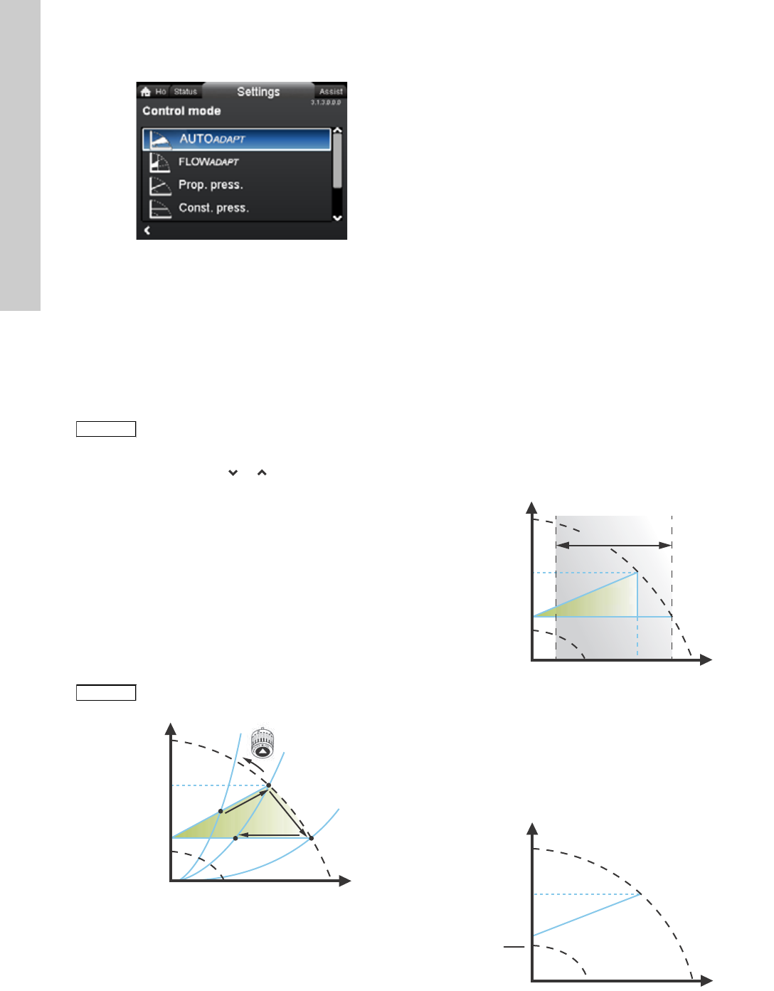
13.3 Control mode
Navigation
Home > Settings > Control mode
Control mode
•AUTO
ADAPT
•FLOW
ADAPT
•Prop. press. (proportional pressure)
•Const. press. (constant pressure)
•Const. temp.(constant temperature)
•Constant curve.
Setting:
1. Select control mode with or .
2. Press [OK] to enable.
The setpoint for all control modes, except AUTOADAPT and
FLOWADAPT, can be changed in the "Setpoint" submenu under
"Settings" when the desired control mode has been selected.
All control modes, except "Constant curve", can be combined with
Automatic Night Setback. See section 13.5
Automatic Night
Setback
.
The FLOWLIMIT function can also be combined with the last four
control modes mentioned above. See section 13.4 FLOWLIMIT.
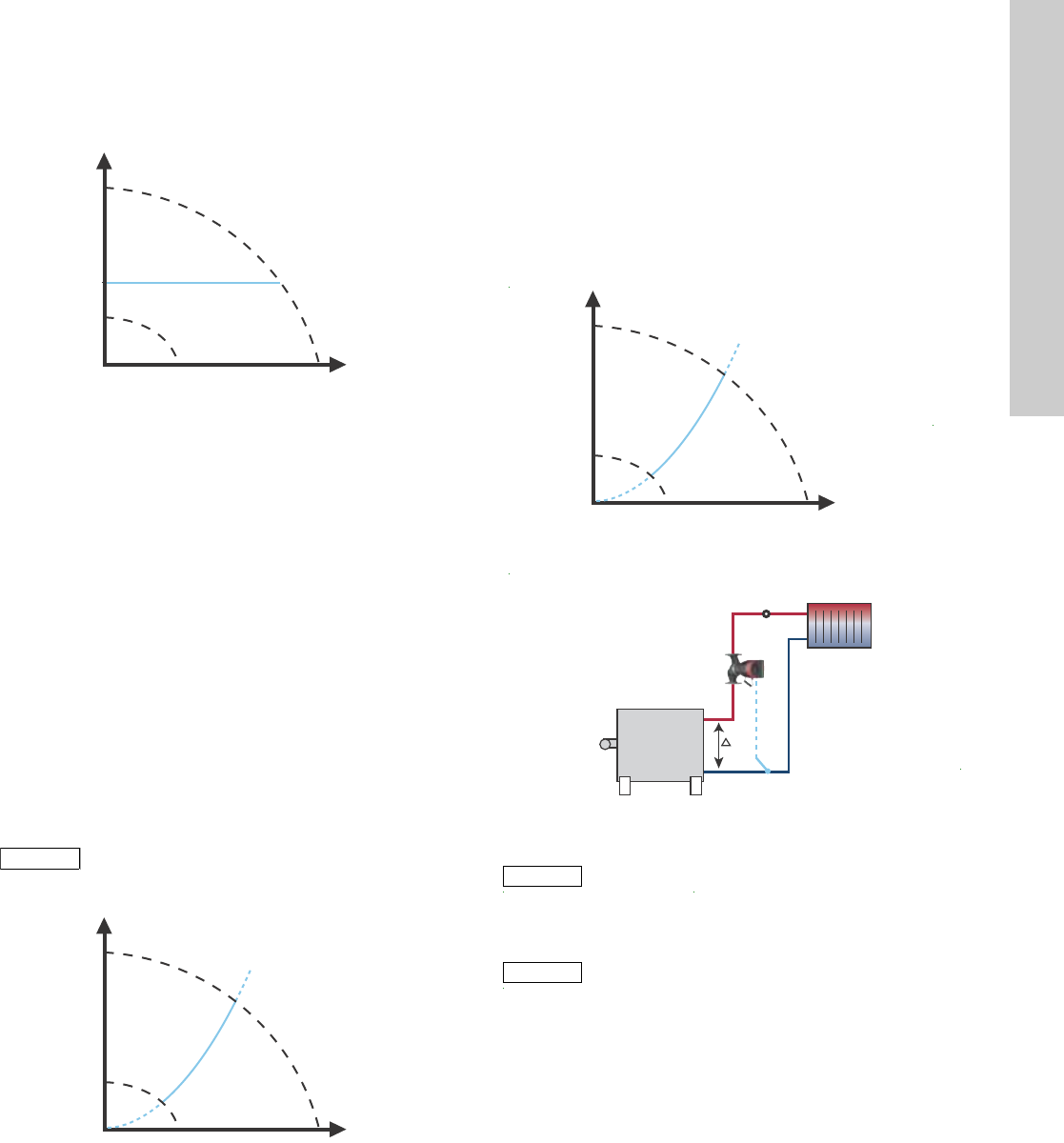
13.3.1 AUTOADAPT
The AUTOADAPT control mode continuously adapts the pump
performance according to the actual system characteristic.
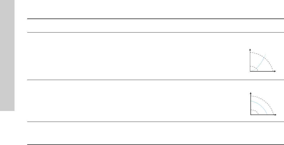
Fig. 21 AUTOADAPT
When the AUTOADAPT control mode has been enabled, the pump
will start with the factory setting, Hfac = Hset1, corresponding to
approx. 55 % of its maximum head, and then adjust its
performance to A1. See fig. 21.
When the pump registers a lower head on the max. curve, A2, the
AUTOADAPT function will automatically select a correspondingly
lower control curve, Hset2. If the valves in the system close, the
pump will adjust its performance to A3.
The AUTOADAPT control mode is a form of proportional-pressure
control where the control curves have a fixed origin, Hauto_min.
The AUTOADAPT control mode has been developed specifically
for heating systems and is not recommended for air-conditioning
and cooling systems.
To reset AUTOADAPT, see section 13.9.8
Return to factory
settings
.
13.3.2 FLOWADAPT
When FLOWADAPT is selected, the pump will run AUTOADAPT and
ensure that the flow never exceeds the entered FLOWLIMIT value.
The setting range for the FLOWLIMIT is 25 to 90 % of the Qmax of
the pump.
The factory setting of the FLOWLIMIT is the flow where the
AUTOADAPT factory setting meets the max. curve. See fig. 22.
Fig. 22 FLOWADAPT
13.3.3 Proportional pressure
The pump head is reduced at decreasing water demand and
increased at rising water demand. See fig. 23.
The setpoint can be set within the range from 1 meter (3.28 ft) to
approx. 1 meter (3.28 ft) below the maximum head, depending on
pump type.
Fig. 23 Proportional pressure
3.1.3.0.0.0 Control mode
Note
Note
The operating mode must be set to "
Normal
"
before a control mode can be enabled.
Note
Note
Manual setting of the setpoint is not possible.
TM05 2452 1312
H
Q
H
auto_min
H
fac
A
1
A
3
A
2
H
set1
H
set2
A1: Original duty point.
A2: Lower registered head on the max. curve.
A3: New duty point after AUTOADAPT control.
Hset1: Original setpoint setting.
Hset2: New setpoint after AUTOADAPT control.
Hfac.: MAGNA3 xx-60: 11.4 ft (3.5 m)
MAGNA3 xx-80: 14.7 ft (4.5 m)
MAGNA3 xx-100: 18 ft (5.5 m)
MAGNA3 xx-120: 21.3 ft (6.5 m)
MAGNA3 xx-150: 26.2 ft (8.0 m)
MAGNA3 xx-180: 31.1 ft (9.5 m).
Hauto_min: A fixed value of 4.9 ft (1.5 m).
TM05 3334 1212 TM05 2448 1212
H
Q
Q
max
25 % 90 %
H
auto_min
H
fac
Q
fac
Setting range
H
Q
Hset
Hset
2
21
English (US)
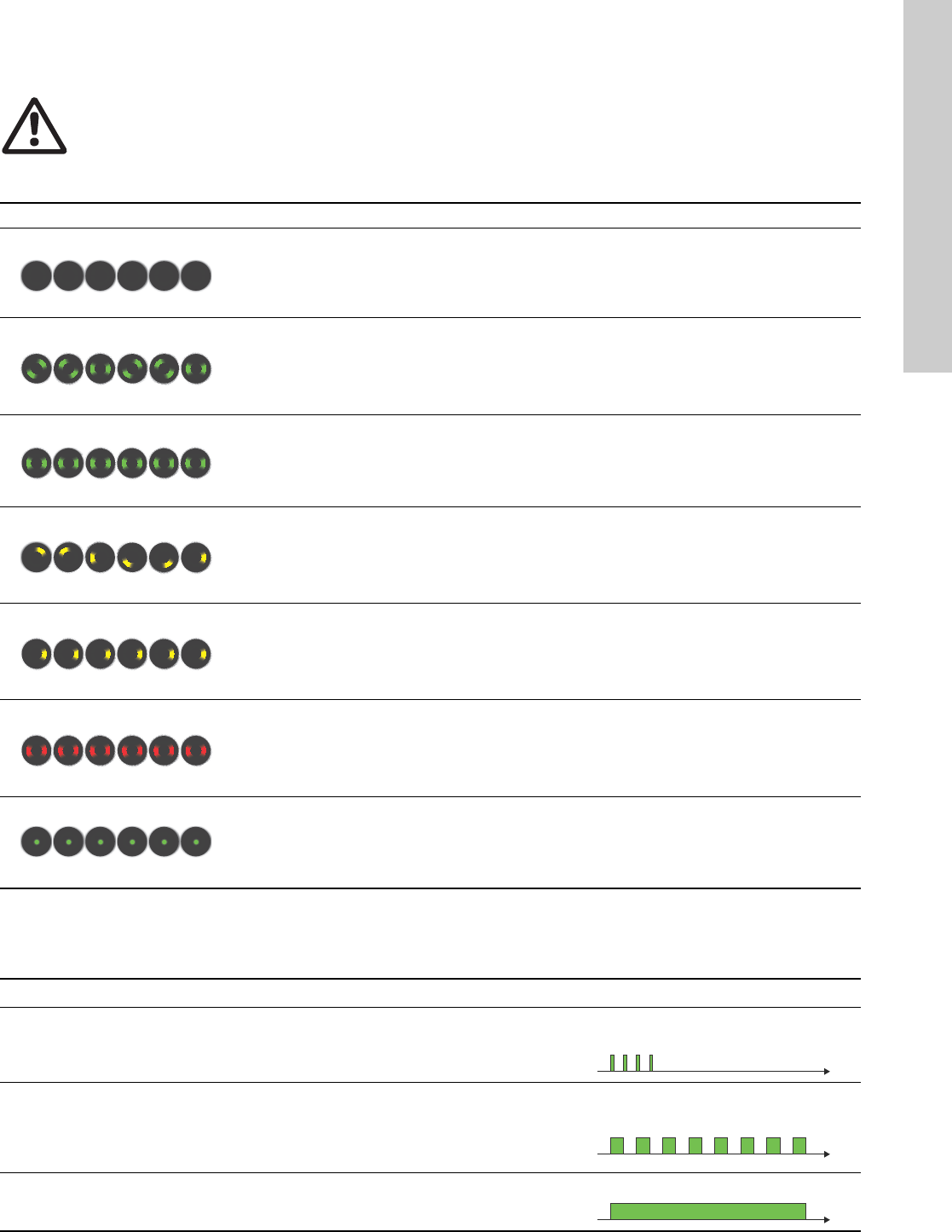
13.3.4 Constant pressure
The pump maintains a constant pressure, irrespective of water
demand. See fig. 24.
Fig. 24 Constant pressure
13.3.5 Constant temperature
This control mode ensures a constant temperature. Constant
temperature is a comfort control mode that can be used in
domestic hot-water systems to control the flow to maintain a fixed
temperature in the system. See fig. 25. When this control mode is
used, no balancing valves must be installed in the system.
If the pump is installed in the return pipe of the system, the
internal temperature sensor can be used. In this case, the pump
must be installed as close as possible to the consumer (radiator,
heat exchanger, etc.).
If the pump is installed in the flow pipe, an external temperature
sensor must be installed in the return pipe of the system. The
sensor must be installed as close as possible to the consumer
(radiator, heat exchanger, etc.).
The constant-temperature control mode also reduces the risk of
bacterial growth (for example Legionella) in the system.
It is possible to set the sensor range:
• min. +14 °F (-10 °C)
• max. +266 °F (+130 °C).
Fig. 25 Constant temperature
13.3.6 Differential temperature
This control mode ensures a constant differential temperature drop
across a heating system.
The pump should be installed in the flow pipe so the built-in sensor
measures the fluid temperature going out to the load. An external
temperature sensor must be installed in the system to measure the
fluid temperature returning from the heating load. In this mode, the
pump will maintain a constant temperature. See fig. 20. and 21.
differential between the pump and the external sensor.
Fig. 26 Differential temperature
Fig. 27 Differential temperature
See table, fig. 28.
TM05 2449 0312
Note
Note
To ensure that the pump is able to control, we
recommend to set the sensor range between
+3 °F and +257 °F (-5 and +125 °C).
TM05 2451 5111
H
Q
H
Q
TM05 2451 5111
TM05
Note
Note
Changing Kp and Ti values are only possible with
Grundfos GO.
Note
Note
Changing the Kp and Ti values will affect all
control modes. If the Control Mode is to be
changed back to another mode you must set the
Kp and Ti values back to default values. For all
other modes the default values are Kp=0.5,
Ti=0.5.
H
Q
Δt
t
English (US)
22
The table shows the suggested controller settings:
Fig. 28 Table, suggested controller settings
1. Heating systems are systems in which an increase in pump
performance will result in a rise in temperature at the sensor.
2. Cooling systems are systems in which an increase in pump
performance will result in a drop in temperature at the sensor.
L1 = Distance in [m] between pump and sensor.
L2 = Distance in [m] between heat exchanger and sensor.
How to set the PI controller
For most applications, the factory setting of the controller
constants Kp and Ti will ensure optimum pump operation.
However, in some applications an adjustment of the controller
may be needed.
Proceed as follows:
1. Increase the gain (Kp) until the motor becomes unstable.
Instability can be seen by observing if the measured value
starts to fluctuate. Furthermore, instability is audible as the
motor starts hunting up and down.
Some systems, such as temperature controls, are
slow-reacting, meaning that it may be several minutes before
the motor becomes unstable.
2. Set the gain (Kp) to half the value of the value which made the
motor unstable. This is the correct setting of the gain.
3. Reduce the integral time (Ti) until the motor becomes
unstable.
4. Set the integral time (Ti) to twice the value which made the
motor unstable. This is the correct setting of the integral time.
General rules of thumb:
• If the controller is too slow-reacting, increase Kp.
• If the controller is hunting or unstable, dampen the system by
reducing Kp or increasing Ti.
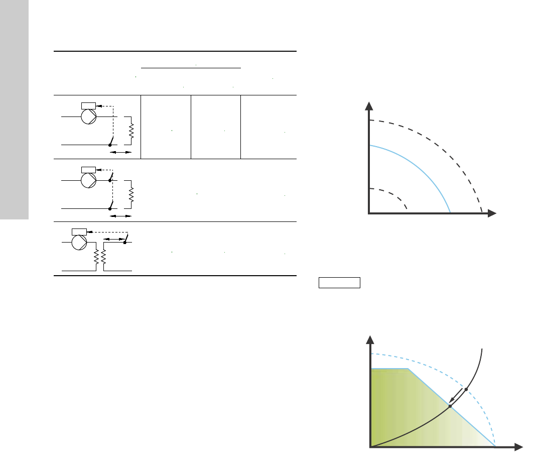
13.3.7 Constant curve
The pump can be set to operate according to a constant curve,
like an uncontrolled pump. See fig. 29.
The desired speed can be set in % of maximum speed in the
range from 25 to 100 %.
Fig. 29 Constant curve
Fig. 30 Power and pressure limitations influencing the max.
curve
System/application
Kp
Ti
Heating
system1)
Cooling
system2)
0.5 - 0.5 10 + 5L2
0.5 10 + 5L2
0.5 - 0.5 30 + 5L2
t
L2 [m]
Δt
L2 [m]
L2 [m]
t
TM05 2446 0312
Note
Note
Depending on the system characteristic and the
duty point, the 100 % setting may be slightly
smaller than the pump’s actual max. curve even
though the display shows 100 %. This is due to
power and pressure limitations built into the
pump. The deviation varies according to pump
type and pressure loss in the pipes.
TM05 3041 1212
H
Q
H [%]
Q [m
3
/h]
100 %
Max. curve
Limited
max. curve
Actual duty point
23
English (US)
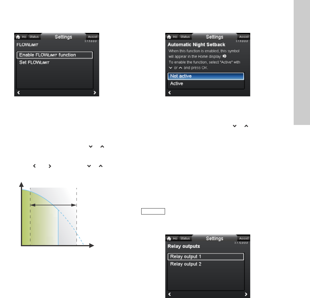
13.4 FLOWLIMIT
Navigation
Home > Settings > FLOWLIMIT
FLOWLIMIT
•Enable FLOWLIMIT function
•Set FLOWLIMIT.
Setting:
1. To enable the function, select "Active" with or and press
[OK].
2. To set the FLOWLIMIT, press [OK] to start the setting.
3. Select digit with and and adjust with or .
4. Press [OK] to save.
Fig. 31 FLOWLIMIT
The FLOWLIMIT function can be combined with the following
control modes:
•Prop. press.
•Const. press.
•Const. temp.
•Constant curve.
A flow-limiting function ensures that the flow never exceeds the
entered FLOWLIMIT value.
The setting range for FLOWLIMIT is 25 to 90 % of the Qmax of the
pump.
The factory setting of the FLOWLIMIT is the flow where the
AUTOADAPT factory setting meets the max. curve. See fig. 22.
13.5 Automatic Night Setback
Navigation
Home > Settings > Automatic Night Setback
Automatic Night Setback
To enable the function, select "Active" with or and press
[OK].
Once Automatic Night Setback has been enabled, the pump
automatically changes between normal duty and night setback
(duty at low performance).
Changeover between normal duty and night setback depends on
the flow-pipe temperature.
The pump automatically changes over to night setback when the
built-in sensor registers a flow-pipe temperature drop of more
than +18 to +27 °F (-8 to -3 °C) within approx. two hours. The
temperature drop must be at least 0.18 °F/min (0.1 °C/min).
Changeover to normal duty takes place without a time lag when
the temperature has increased by approx. +18 °F (-8 °C).
13.6 Relay outputs
Navigation
Home > Settings > Relay outputs
Relay outputs
•Relay output 1
•Relay output 2.
The relay outputs can be set to the following:
•Not active
•Ready
•Alarm
•Operation.
The pump incorporates two signal relays, terminals 1, 2 and 3, for
a potential-free alarm signal, ready signal and operating signal.
For further information, see section 5.5.1 Relay outputs.
Set the function of the signal relays, alarm signal (factory setting),
ready signal and operating signal, on the pump control panel.
The output, terminals 1, 2 and 3, is electrically separated from the
rest of the controller.
3.1.5.0.0.0 FLOWLIMIT
TM05 2445 1212
H
Q
Q
max
Q
max
Q
limit
25 % 90 %
Setting range
3.1.6.0.0.0 Automatic Night Setback
Note
Note
Automatic Night Setback cannot be enabled
when the pump is in constant-curve mode.
3.1.12.0.0.0 Relay outputs
English (US)
24
The signal relay is operated as follows:
•Not active
The signal relay is deactivated.
•Ready
The signal relay is active when the pump is running or has
been set to stop, but is ready to run.
•Alarm
The signal relay is activated together with the red indicator
light on the pump.
•Operation
The signal relay is activated together with the green indicator
light on the pump.
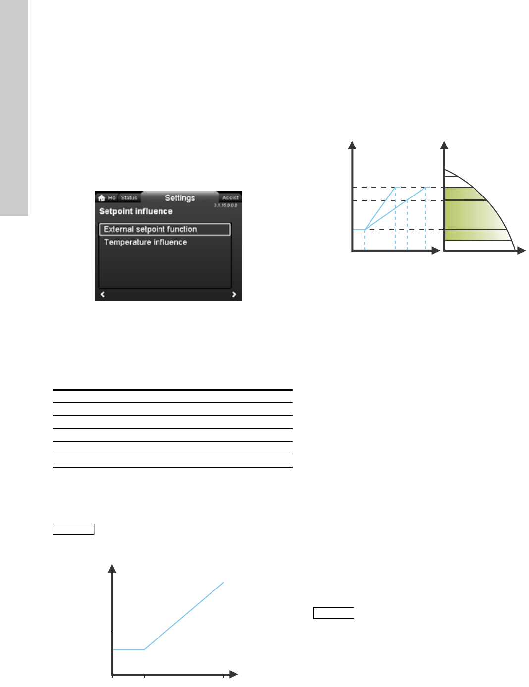
13.7 Setpoint influence
Navigation
Home > Settings > Setpoint influence
Setpoint influence
•External setpoint function
•Temperature influence.
13.7.1 External setpoint function
The external setpoint function is an external 0-10 V or 4-20 mA
signal that will control the pump speed in a range from 0 to 100 %
in a linear function. See fig. 32.
Fig. 32 External setpoint function, 0-10 V
13.7.2 Temperature influence
When this function is enabled in proportional- or
constant-pressure control mode, the setpoint for head will be
reduced according to the liquid temperature.
Temperature influence can be set to function at liquid
temperatures below +176 °F or +122 °F (80 °C or 50 °C). These
temperature limits are called Tmax.. The setpoint is reduced in
relation to the head set (= 100 %) according to the characteristics
below.
Fig. 33 Temperature influence
In the above example, Tmax. = +176 °F (+80 °C) has been
selected.
The actual liquid temperature Tactual causes the setpoint for head
to be reduced from 100 % to Hactual.
The temperature influence function requires the following:
• Proportional-pressure, constant-pressure or constant-curve
control mode.
• Pump installed in flow pipe.
• System with flow-pipe temperature control.
Temperature influence is suitable for the following systems:
• Systems with variable flows (for example two-pipe heating
systems) in which the enabling of the temperature influence
function will ensure a further reduction of the pump
performance in periods with small heating demands and
consequently a reduced flow-pipe temperature.
• Systems with almost constant flows (for example one-pipe
heating systems and underfloor heating systems), in which
variable heating demands cannot be registered as changes in
the head as is the case with two-pipe heating systems. In such
systems, the pump performance can only be adjusted by
enabling the temperature influence function.
Selection of Tmax.
In systems with a dimensioned flow-pipe temperature of:
• up to and including +131 °F (+55 °C),
select Tmax. = +122 °F (+50 °C)
• above +131 °F (+55 °C), select Tmax. = +176 °F (80 °C).
3.1.15.0.0.0 Setpoint influence
Range
4-20 mA [0-100 %]
0-10 V [0-100 %]
Control
0-20 % (e.g. 0-2 V) Setpoint = Min.
20-100 % (e.g. 2-10 V) Setpoint = Min. ↔ setpoint
Note
Note
Before the "
External setpoint function
" can be
enabled, the analog input must be set to
"
External setpoint influence
" via the "
Assist
" menu.
See section 5.5.3 Analog input.
TM05 3219 1212
rpm
V
Min.
02
Max.
10
TM05 7946 1613
Note
Note
The temperature influence function cannot be
used in air-conditioning and cooling systems.
H
T [°F]
30 %
68 122 176
T [°C]
20 50 80
100 %
Hactual
Tactual
H
Q
25
English (US)
13.8 Bus communication
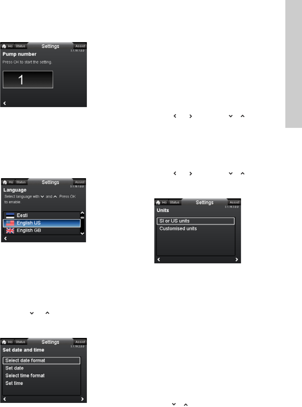
13.8.1 Pump number
Navigation
Home > Settings > Bus communication > Pump number
Pump number
A unique number can be allocated to the pump. This makes it
possible to distinguish between pumps in connection with bus
communication.
13.9 General settings
13.9.1 Language
Navigation
Home > Settings > General settings > Language
Language
The display can be shown in any of the following languages:
GB, BG, CZ, DK, DE, EE, GR, ES, FR, HR, IT, LV, LT, HU, NL,
UA, PL, PT, RU, RO, SK, SI, RS, FI, SE, TR, CN, JP or KO.
Measuring units are automatically changed according to selected
language.
Setting:
1. Select language with and .
2. Press [OK] to enable.
13.9.2 Set date and time
Navigation
Home > Settings > General settings > Set date and time
Set date and time
•Select date format
•Set date
•Select time format
•Set time.
Set the real-time clock in this menu.
Select date format
•YYYY-MM-DD
•DD-MM-YYYY
•MM-DD-YYYY.
Setting:
1. Select "Set date".
2. Press [OK] to start the setting.
3. Select digit with and and adjust with or .
4. Press [OK] to save.
Select time format
•HH:MM 24-hour clock
•HH:MM am/pm 12-hour clock.
Setting:
1. Select "Set time".
2. Press [OK] to start the setting.
3. Select digit with and and adjust with or .
4. Press [OK] to save.
13.9.3 Units
Navigation
Home > Settings > General settings > Units
Units
•SI or US units
• Customized units.
Select whether the display should shows SI or US units or select
the desired units for the parameters below.
•Pressure
•Differential pressure
•Head
•Level
•Flow rate
•Volume
•Temperature
•Differential temp.
•Power
•Energy.
Setting:
1. Select parameter and press [OK].
2. Select unit with or .
3. Press [OK] to enable.
If "SI or US units" is selected, the customized units will be reset.
3.1.18.1.0.0 Pump number
TM05 7947 1613
3.1.19.2.0.0 Set date and time
3.1.19.3.0.0 Units
English (US)
26
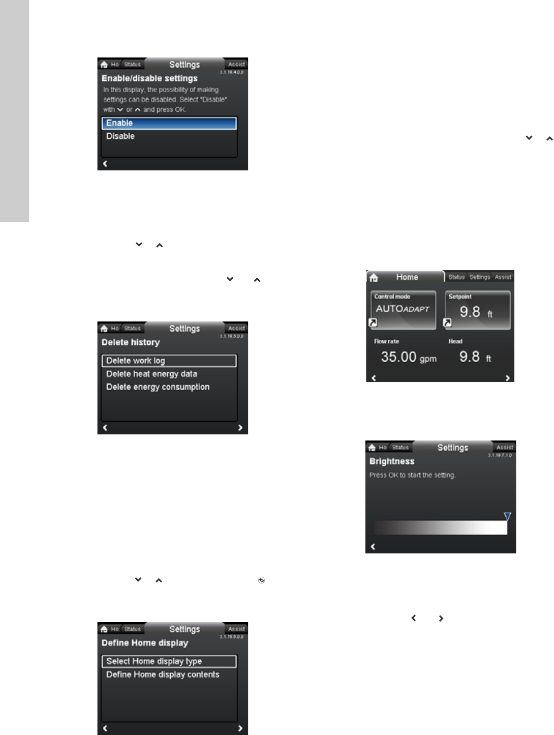
13.9.4 Enable/disable settings
Navigation
Home > Settings > General settings > Enable/disable settings
Enable/disable settings
In this display, the possibility of making settings can be disabled
for protective reasons.
Select "Disable" with or and press [OK].
The pump will now be locked for settings. Only the "Home"
display will be available.
To unlock the pump and allow settings, press and
simultaneously for at least 5 seconds.
13.9.5 Delete history
Navigation
Home > Settings > General settings > Delete history
Delete history
•Delete work log
•Delete heat energy data
•Delete energy consumption.
It is possible to delete data from the pump, for example if the
pump is moved to another system or if new data are required due
to changes to the system.
Setting:
1. Select the relevant submenu and press [OK].
2. Select "Yes" with or and press [OK] or press to
cancel.
13.9.6 Define Home display
Navigation
Home > Settings > General settings > Define Home display
Define Home display
•Select Home display type
•Define Home display contents.
The "Home" display can be set to show up to four user-defined
parameters or a graphical illustration of a performance curve.
Select Home display type
1. Select "List of data" or "Graphical illustration" with or .
2. Press [OK] to save.
To specify the contents, go to "Define Home display contents".
Define Home display contents
1. To set "List of data", press [OK] to start the setting.
A list of parameters will appear in the display.
2. Select or deselect with [OK].
Up to four parameters can be selected.
The selected parameters will be shown as illustrated below.
The arrow icon indicates that the parameter links to the "Settings"
menu and works as a shortcut for quick settings.
1. To set "Graphical illustration", press [OK] to start the setting.
2. Select the desired curve and press [OK] to save.
13.9.7 Display brightness
Navigation
Home > Settings > General settings > Display brightness
Brightness
1. Press [OK] to start the setting.
2. Set brightness with and .
3. Press [OK] to save.
3.1.19.4.0.0 Enable/disable settings3.1.19.5.0.0 Delete history3.1.19.6.0.0 Define Home display
TM05 7929 1613
3.1.19.7.1.0 Brightness
27
English (US)
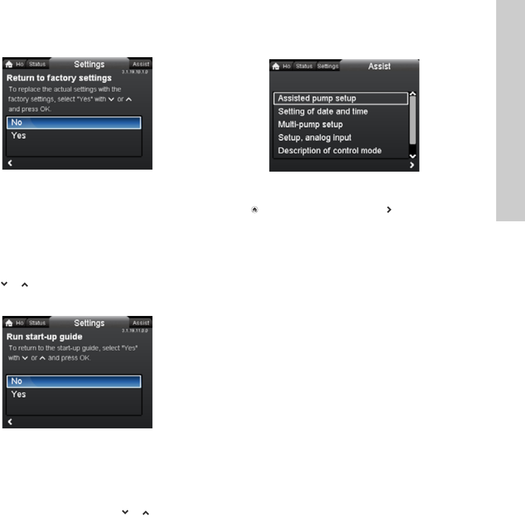
13.9.8 Return to factory settings
Navigation
Home > Settings > General settings > Return to factory settings
Return to factory settings
It is possible to recall the factory settings and overwrite the
current settings. All user settings in the "Settings" and "Assist"
menus will be set back to the factory settings. This also includes
language, units, possible setup of analog input, multi-pump
function, etc.
To overwrite the current settings with the factory settings, select
"Yes" with or and press [OK].
13.9.9 Run start-up guide
Navigation
Home > Settings > General settings > Run start-up guide
Run start-up guide
It is possible to run the start-up guide again. The start-up guide
will guide the user through the general settings of the pump, such
as language, date and time.
To run the start-up guide, select "Yes" with or and press
[OK].
14. "Assist" menu
Navigation
Home > Assist
Press and go to the "Assist" menu with .
"Assist" menu
This menu offers the following:
•Assisted pump setup
•Setting of date and time
•Multi-pump setup
•Setup, analog input
•Description of control mode
•Assisted fault advice.
The "Assist" menu guides the user through the setting of the
pump. In each submenu, the user is presented with a guide that
helps throughout the setting.
14.1 Assisted pump setup
This submenu is a step-by-step guide to complete pump setup,
starting with a presentation of the control modes and ending with
the setpoint setting.
14.2 Setting of date and time
See section 13.9.2
Set date and time
.
14.3 Multi-pump setup
This submenu assists the user in setting up a multi-pump system.
See section 14.8 Multi-pump function.
14.4 Setup, analog input
This submenu assists the user in setting up the analog input.
14.5 Description of control mode
This submenu gives a short description of each control mode.
14.6 Assisted fault advice
This submenu provides information about faults and corrective
actions.
14.7 Wireless GENIair
The pump is designed for multi-pump connection via the wireless
GENIair connection or wired via a bus system
(Building Management System).
The built-in wireless GENIair module enables communication
between pumps and with the Grundfos Go Remote without the
use of add-on modules:
• Multi-pump function.
See section 14.8 Multi-pump function.
• Grundfos GO Remote.
See section 18.1 Grundfos GO Remote.
3.1.19.10.1.0 Return to factory settings3.1.19.11.0.0 Run start-up guide
Assist

English (US)
28
14.8 Multi-pump function
The multi-pump function enables the control of single-head
pumps connected in parallel and twin-head pumps without the
use of external controllers. The pumps in a multi-pump system
communicate with each other via the wireless GENIair
connection.
A multi-pump system is set up via a selected pump, i.e. the
master pump (first selected pump). All Grundfos pumps with a
wireless GENIair connection can be connected to the multi-pump
system.
The multi-pump functions are described in the following sections.
14.8.1 Alternating operation
Only one pump is operating at a time. The change from one pump
to the other depends on time or energy. If a pump fails, the other
pump will take over automatically.
Pump system:
• Twin-head pump.
• Two single-head pumps connected in parallel. The pumps
must be of same type and size. Each pump requires a
non-return valve in series with the pump.
14.8.2 Back-up operation
One pump is operating continuously. The back-up pump is
operated at intervals to prevent seizing up. If the duty pump stops
due to a fault, the back-up pump will start automatically.
Pump system:
• Twin-head pump.
• Two single-head pumps connected in parallel. The pumps
must be of same type and size. Each pump requires a
non-return valve in series with the pump.
14.8.3 Cascade operation
Cascade operation ensures that the pump performance is
automatically adapted to the consumption by switching pumps on
or off. The system thus runs as energy-efficiently as possible with
a constant pressure and a limited number of pumps.
All pumps in operation will run at equal speed. Pump changeover
is automatic and depends on energy, operating hours and fault.
Pump system:
• Twin-head pump.
• Two single-head pumps connected in parallel. The pumps
must be of same type and size. Each pump requires a
non-return valve in series with the pump.
• The control mode must be set to "Const. press." or "Constant
curve".
29
English (US)
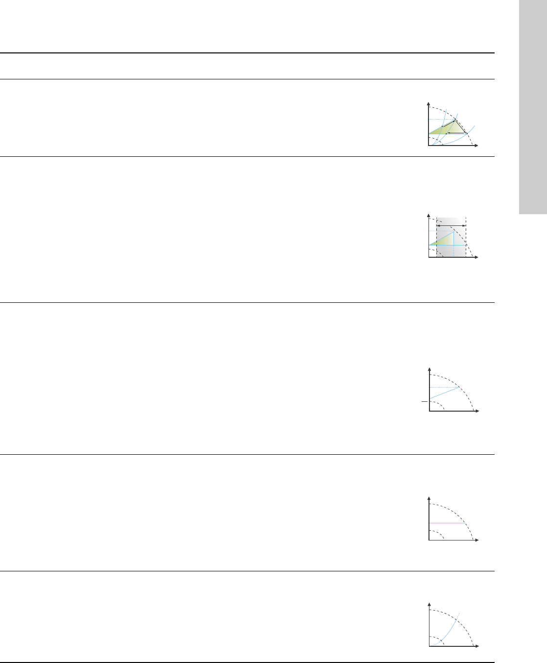
15. Selection of control mode
System application Select this control
mode
Recommended for most heating systems, especially in systems with relatively large pressure losses in the
distribution pipes. See description under proportional pressure.
In replacement situations where the proportional-pressure duty point is unknown.
The duty point has to be within the AUTOADAPT operating range. During operation, the pump automatically
makes the necessary adjustment to the actual system characteristic.
This setting ensures minimum energy consumption and noise level from valves, which reduces operating costs
and increases comfort.
AUTOADAPT
The FLOWADAPT control mode is a combination of AUTOADAPT and FLOWLIMIT.
This control mode is suitable for systems where a maximum flow limit, FLOWLIMIT, is desired. The pump
continuously monitors and adjusts the flow, thus ensuring that the selected FLOWLIMIT is not exceeded.
Main pumps in boiler applications where a steady flow through the boiler is required. No extra energy is used for
pumping too much liquid into the system.
In systems with mixing loops, the control mode can be used to control the flow in each loop.
Benefits:
• Enough water for all loops at peak load conditions if each loop has been set to the right maximum flow.
• The dimensioned flow for each zone (required heat energy) is determined by the flow from the pump.
This value can be set precisely in the FLOWADAPT control mode without the use of pump throttling valves.
• When the flow is set lower than the balancing valve setting, the pump will ramp down instead of losing energy
by pumping against a balancing valve.
• Cooling surfaces in air-conditioning systems can operate at high pressure and low flow.
FLOWADAPT
In systems with relatively large pressure losses in the distribution pipes and in air-conditioning and cooling systems.
• Two-pipe heating systems with thermostatic valves and
– a dimensioned pump head higher than 13 ft (4 meters)
– very long distribution pipes
– strongly throttled pipe balancing valves
– differential-pressure regulators
– large pressure losses in those parts of the system through which the total quantity of water flows
(for example boiler, heat exchanger and distribution pipe up to the first branching).
• Primary circuit pumps in systems with large pressure losses in the primary circuit.
• Air-conditioning systems with
– heat exchangers (fan coils)
– cooling ceilings
– cooling surfaces.
Proportional
pressure
In systems with relatively small pressure losses in the distribution pipes.
• Two-pipe heating systems with thermostatic valves and
– a dimensioned pump head lower than 6.5 ft (2 meters)
– dimensioned for natural circulation
– small pressure losses in those parts of the system through which the total quantity of water flows
(for example boiler, heat exchanger and distribution pipe up to the first branching) or
– modified to a high differential temperature between flow pipe and return pipe (for example district heating).
• Underfloor heating systems with thermostatic valves.
• One-pipe heating systems with thermostatic valves or pipe balancing valves.
• Primary circuit pumps in systems with small pressure losses in the primary circuit.
Constant pressure
In heating systems with a fixed system characteristic, for example domestic hot-water systems, the control of the
pump according to a constant return-pipe temperature may be relevant.
FLOWLIMIT can be used with advantage to control the maximum circulation flow.
Constant
temperature
H
Q
H
Q
H
Q
H
set
H
set
2
H
Q
H
Q
English (US)
30
In a heating system where a constant temperature drop across the system is desired, constant differential
temperature can be used.
Differential
temperature
If an external controller is installed, the pump is able to change from one constant curve to another, depending
on the value of the external signal.
The pump can also be set to operate according to the max. or min. curve, like an uncontrolled pump:
• The max. curve mode can be used in periods in which a maximum flow is required. This operating mode is for
instance suitable for hot-water priority.
• The min. curve mode can be used in periods in which a minimum flow is required. This operating mode is for
instance suitable for manual night setback if Automatic Night Setback is not desired.
Constant curve
In systems with pumps operating in parallel.
The multi-pump function enables the control of single-head pumps connected in parallel (two pumps) and
twin-head pumps without the use of external controllers. The pumps in a multi-pump system communicate with
each other via the wireless GENIair connection.
"Assist" menu
"Multi-pump setup"
System application Select this control
mode
H
Q
ΔT
H
Q
31
English (US)
16. Fault finding
16.1 Grundfos Eye operating indications
16.2 Signalling communication with remote control
The centre indicator light in the Grundfos Eye will indicate communication with the Grundfos GO Remote.
The table below describes the desired function of the center indicator light.
Warning
Before dismantling the pump, drain the system or close the isolating valve on either side of the pump. The pumped
liquid may be scalding hot and under high pressure.
Grundfos Eye Indication Cause
No lights on. Power off.
Pump not running.
Two opposite green indicator lights running in the
direction of rotation of the pump.
Power on.
Pump running.
Two opposite green indicator lights permanently
on.
Power on.
Pump not running.
One yellow indicator light running in the direction
of rotation of the pump.
Warning.
Pump running.
One yellow indicator light permanently on. Warning.
Pump stopped.
Two opposite red indicator lights flashing
simultaneously.
Alarm.
Pump stopped.
One green indicator light in the middle
permanently on (in addition to another
indication).
Remote-controlled.
The pump is currently being accessed by the
Grundfos GO Remote.
Case Description Signalling by the centre indicator light
Wink
The pump in question is highlighted in the Grundfos GO Remote display.
To inform the user of the location of the highlighted pump, the center
indicator light will flash four or five times once to signal "I am here".
Four or five quick flashes once to signal
"I am here".
Push me
The pump in question is selected/opened in the Grundfos GO Remote
menu. The pump will signal "Push me" to ask the user to select the
pump/allow the pump to exchange data with the Grundfos GO Remote.
The indicator light will flash continuously until a pop-up window asks the
user to press [OK] to allow communication with the Grundfos GO Remote.
Flashing continuously with 50 % duty
cycle.
I am connected
The indicator light is signalling that the pump is connected to
Grundfos GO Remote. The indicator light is permanently on as long as the
pump is selected in the Grundfos GO Remote.
Indicator light permanently on.

English (US)
32
16.3 Fault finding
A fault indication can be reset in one of the following ways:
• When the fault cause has been eliminated, the pump will
revert to normal duty.
• If the fault disappears by itself, the fault indication will
automatically be reset.
• The fault cause will be stored in the pump alarm log.
Warning and alarm codes Fault Automatic reset
and restart? Corrective actions
Pump communication fault (10)
Alarm
Communication fault between
different parts of the
electronics.
Yes Replace the pump, or call GRUNDFOS
SERVICE for assistance.
Forced pumping (29)
Alarm
Other pumps or sources force
flow through the pump even if
the pump is stopped.
Yes
Check the system for defective non-return valves
and replace, if necessary.
Check the system for correct position of
non-return valves, etc.
Undervoltage (40, 75)
Alarm
Supply voltage to the pump
too low. Yes Check that the power supply is within the
specified range.
Blocked pump (51)
Alarm The pump is blocked. No
Dismantle the pump, and remove any foreign
matter or impurities preventing the pump from
rotating.
Dry running (57)
Alarm
No water at the pump inlet or
the water contains too much
air.
No
Prime and vent the pump before a new start-up.
Check that the pump is operating correctly. If not,
replace the pump, or call GRUNDFOS SERVICE
for assistance.
Internal fault (72, 84, 155, 157)
Warning/alarm
Internal fault in the pump
electronics. Yes Replace the pump, or call GRUNDFOS
SERVICE for assistance.
Overvoltage (74)
Alarm
Supply voltage to the pump
too high. Yes Check that the power supply is within the
specified range.
Internal sensor fault (88)
Warning
The pump is receiving a signal
from the internal sensor which
is outside the normal range.
Yes
Check that the plug and cable are connected
correctly in the sensor. The sensor is located on
the back of the pump housing.
Replace the sensor, or call GRUNDFOS
SERVICE for assistance.
External sensor fault (93)
Warning
The pump is receiving a signal
from the external sensor which
is outside the normal range.
Yes
Does the electrical signal set (0-10 V or 4-20 mA)
match the sensor output signal?
If not, change the setting of the analog input, or
replace the sensor with one that matches the
setup.
Check the sensor cable for damage.
Check the cable connection at the pump and at
the sensor. Correct the connection, if required.
The sensor has been removed, but the analog
input has not been disabled.
Replace the sensor, or call GRUNDFOS
SERVICE for assistance.
Caution
If the power supply cable is damaged, it must be replaced by the manufacturer, the manufacturer’s service partner or
a similarly qualified person.
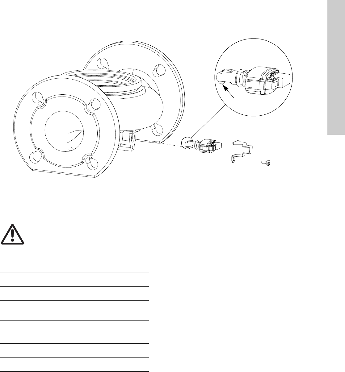
33
English (US)
17. Sensor
Fig. 34 Correct position of sensor
During maintenance and replacement of the sensor, it is
important that the sealing cap is fitted correctly on the sensor
housing.
Tighten the screw holding the clamp to 3.7 ft-lbs (5 Nm).
17.1 Sensor specifications
17.1.1 Pressure
* Full scale.
17.1.2 Temperature
TM05 3036 0812
Nose downwards
5 Nm
Warning
Before replacing the sensor, make sure that the
pump is stopped and that the system is not
pressurized.
Maximum differential pressure
during operation 29 psi / 2 bar / 0.2 MPa
Accuracy
+32 to +185 °F (0 to +85 °C) 2 % *
Accuracy
+14 to +32 °F and +185 to +266 °F
(-10 to 0 °C and +85 to +130 °C)
3 % *
Temperature range during operation +14 to +266 °F
(-10 to +130 °C)
Accuracy ± 5.6 °F
(± 2 °C)
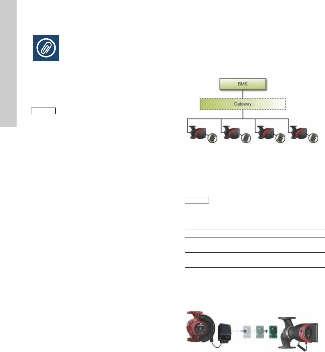
English (US)
34
18. Accessories
18.1 Grundfos GO Remote
The MAGNA3 is designed for wireless communication with the
Grundfos GO Remote app. The Grundfos GO Remote app
communicates with the pump via radio communication
(wireless GENIair).
The Grundfos GO Remote app is available from Apple AppStore
and Android market.
The Grundfos GO Remote concept replaces the Grundfos R100
remote control. This means that all products supported by the
R100 are supported by the Grundfos GO Remote.
The Grundfos GO Remote can be used for the following:
• Reading of operating data.
• Reading of warning and alarm indications.
• Setting of control mode.
• Setting of setpoint.
• Selection of external setpoint signal.
• Allocation of pump number making it possible to distinguish
between pumps that are connected via Grundfos GENIbus.
• Selection of function for digital input.
• Generation of reports (PDF).
• Assist function.
• Multi-pump setup.
• Display of relevant documentation.
For function and connection to the pump, see separate
installation and operating instructions for the desired type of
Grundfos GO Remote setup.
18.2 Communication
The pump can communicate via the wireless GENIair connection
or a CIM module.
This enables the pump to communicate with other pumps and
with different types of network solutions.
The Grundfos CIM modules (CIM = Communication Interface
Module) enable the pump to connect to standard fieldbus
networks.
Fig. 35 Building management system (BMS) with four pumps
connected in parallel
A CIM module is an add-on communication interface module.
The CIM module enables data transmission between the pump
and an external system, for example a BMS or SCADA system.
The CIM module communicates via fieldbus protocols.
The following CIM modules are available:
18.2.1 Reuse of CIM modules
A CIM module in a CIU unit used together with
GRUNDFOS MAGNA can be reused in MAGNA3.
The CIM module has to be re-configured before it is used in a
MAGNA3 pump. Contact your nearest Grundfos company.
Fig. 36 Reuse of CIM module
Note
Note
The radio communication between the pump and
the Grundfos GO Remote is encrypted to protect
against misuse.
TM05 2710 0612
Note
Note
A gateway is a device that facilitates the transfer
of data between two different networks based on
different communication protocols.
Module Fieldbus protocol Product number
CIM 050 GENIbus 96236335
CIM 100 LONworks 96753735
CIM 150 Profibus DP 96753081
CIM 200 Modbus RTU 96753082
CIM 300 BACnet MS/TP 96893769
TM05 2911 1312
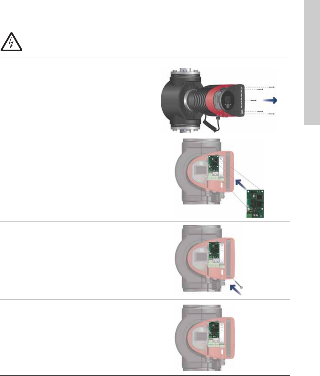
35
English (US)
18.3 Fitting the CIM module
Warning
Before fitting the module, switch off the power supply. Make sure that the power supply cannot be accidentally
switched on.
Step Action Illustration
1 Remove the front cover from the control box.
TM05 2875 0912
2 Fit the CIM module as illustrated and click it on.
TM05 2914 1112
3Fit and tighten the screw holding the CIM module and
secure the earth connection.
TM05 2912 1112
4
For connection to fieldbus networks, see separate
installation and operating instructions for the desired
CIM module.
TM05 2913 1112

English (US)
36
19. Technical data
Supply voltage
See Pump Nameplate for Rated Supply Voltage:
1 x 115 V ± 10 %, 50/60 Hz, PE.
1 x 208-230 V ± 10 %, 50/60 Hz, PE.
Motor protection
The pump requires no external motor protection.
Enclosure class
Enclosure Type 2.
Insulation class
F.
Relative air humidity
Maximum 95 %.
Ambient temperature
+32 °F to +104 °F (0 °C to +40 °C).
During transport: -40 °F to +158 °F (-40 °C to +70 °C).
Temperature class
TF110 (EN 60335-2-51).
Liquid temperature
Continuously: +14 °F to +230 °F (-10 °C to +110 °C).
Stainless-steel pumps in domestic hot-water systems:
In domestic hot-water systems, we recommend to keep the liquid
temperature below +150 °F (+65 °C) to eliminate the risk of lime
precipitation.
System pressure
The maximum permissible system pressure is stated on the pump
nameplate:
175 psi (12 bar).
Inlet pressure
Recommended inlet pressures:
Single-head pumps:
• Min. 1.5 psi / 0.10 bar / 0.01 MPa at +167 °F (+75 °C)
• Min. 5 psi / 0.35 bar / 0.035 MPa at +203 °F (+95 °C)
• Min. 9.5 psi / 0.65 bar / 0.065 MPa at +230 °F (+110 °C).
Twin-head pumps:
• Min. 13 psi / 0.90 bar / 0.09 MPa at +167 °F (+75 °C)
• Min. 17.5 psi / 1.20 bar / 0.12 MPa at +203 °F (+95 °C)
• Min. 22 psi / 1.50 bar / 0.15 MPa at +230 °F (+110 °C).
EMC (electromagnetic compatibility)
EN 55014-1:2006, EN 55014-2:1998, EN 61800-3-3:2008 and
EN 61000-3-2:2006.
Sound pressure level
The sound pressure level of the pump is lower than 43 dB(A).
Leakage current
The pump mains filter will cause a discharge current to earth
during operation. Ileakage < 3.5 mA.
Consumption when the pump is stopped
1 to 10 W, depending on activity, i.e. reading the display, use of
Grundfos GO Remote, interaction with modules, etc.
Input/output communication
cos φ
The MAGNA3 has a built-in active PFC (Power Factor Correction)
which gives a cos φ from 0.98 to 0.99, i.e. very close to 1.
20. Disposal
This product has been designed with focus on the disposal and
recycling of materials. The following disposal values apply to all
variants of Grundfos MAGNA3 pumps:
• minimum 85 % recycling
• maximum 10 % incineration
• maximum 5 % depositing.
Values in percent of total weight.
This product or parts of it must be disposed of in an
environmentally sound way according to local regulations.
Subject to alterations.
Two digital inputs
External potential-free contact.
Contact load: 5 V, 10 mA.
Screened cable.
Loop resistance: Maximum 130 Ω.
Analog input 4-20 mA (load: 150 Ω).
0-10 VDC (load: 78 kΩ).
Two relay outputs
Internal potential-free changeover contact.
Maximum load: 250 V, 2 A, AC1.
Minimum load: 5 VDC, 20 mA.
Screened cable, depending on signal level.
37
38

Grundfos companies
USA
GRUNDFOS Pumps Corporation
17100 West 118th Terrace
Olathe, Kansas 66061
Phone: +1-913-227-3400
Telefax: +1-913-227-3500
Canada
GRUNDFOS Canada Inc.
2941 Brighton Road
Oakville, Ontario
L6H 6C9
Phone: +1-905 829 9533
Telefax: +1-905 829 9512
México
Bombas GRUNDFOS de México S.A. de C.V.
Boulevard TLC No. 15
Parque Industrial Stiva
Aeropuerto
Apodaca, N.L.C.P. 66600
Phone: +52-81-8144 4000
Telefax: +52-81-8144 4010

www.grundfos.us
L-MAG-TL-09
98459408 0513
ECM: 1112321
The name Grundfos, the Grundfos logo, and be think innovate are registered trademarks owned by Grundfos Holding A/S or Grundfos A/S, Denmark. All rights reserved worldwide. © Copyright Grundfos Holding A/S
www.grundfos.com
