539169 3 Goulds Aquavar Solo Product Overview
: Pump 539169 3 Goulds Aquavar Solo Product Overview 539169_3_Goulds Aquavar Solo Product Overview pdf
Open the PDF directly: View PDF ![]() .
.
Page Count: 8
AQUAVAR SOLO™
CONSTANT PRESSURE CONTROLLERS FOR: 1Ø – 3-WIRE MOTORS,
1Ø – 2-WIRE CENTRIPRO MOTORS, 3Ø MOTORS
TECHNICAL BROCHURE
BAQSOLO R3
Residential Water Systems
CentriPro
NSF/ANSI 61-G
®
Drinking Water System Components – Health Effects
& Optional Annex G - Class 6861 18 - Mechanical
Devices - NSF/ANSI 61 - Certied to NSF/ANSI 61
Sect. 8 (including optional Annex G)
PAGE 2
CU
S
®Tested to UL 508C and CSA 22.2 0-M91, 14-95 and 0.4-
M1982 Standards By Canadian Standards Association
File #LR38549
FEATURES
NEMA 3R Enclosure: Rainproof, outdoor/indoor rated
enclosure.
Current Limit Selector Switch: Rotary switch to set
current limit to match motor Service Factor Amps
(SFA).
Dry Well Sensitivity Switch: Choice of low or high
sensitivity.
Pressure Drop: Choose a 5 or 20 PSI pressure drop for
restarts.
Low Pressure Cut-Off: Set on or off depending on
application.
Constant Pressure: Provides consistent pressure even
as ow requirements vary.
Controller acts as a pump protection and
troubleshooting device. Flashing lights indicate
system faults.
Standard pressure sensor cable is 10' long. Optional
lengths of 25', 50', 100', 150' and 200' are available.
Integrated output motor lter protects the motor
from voltage spikes and limits electrical interference
with devices such as portable telephones, radios,
televisions and garage door openers.
Cooling Fan: Allows operation in ambient tempera-
tures up to 122ºF.
AGENCY LISTINGS
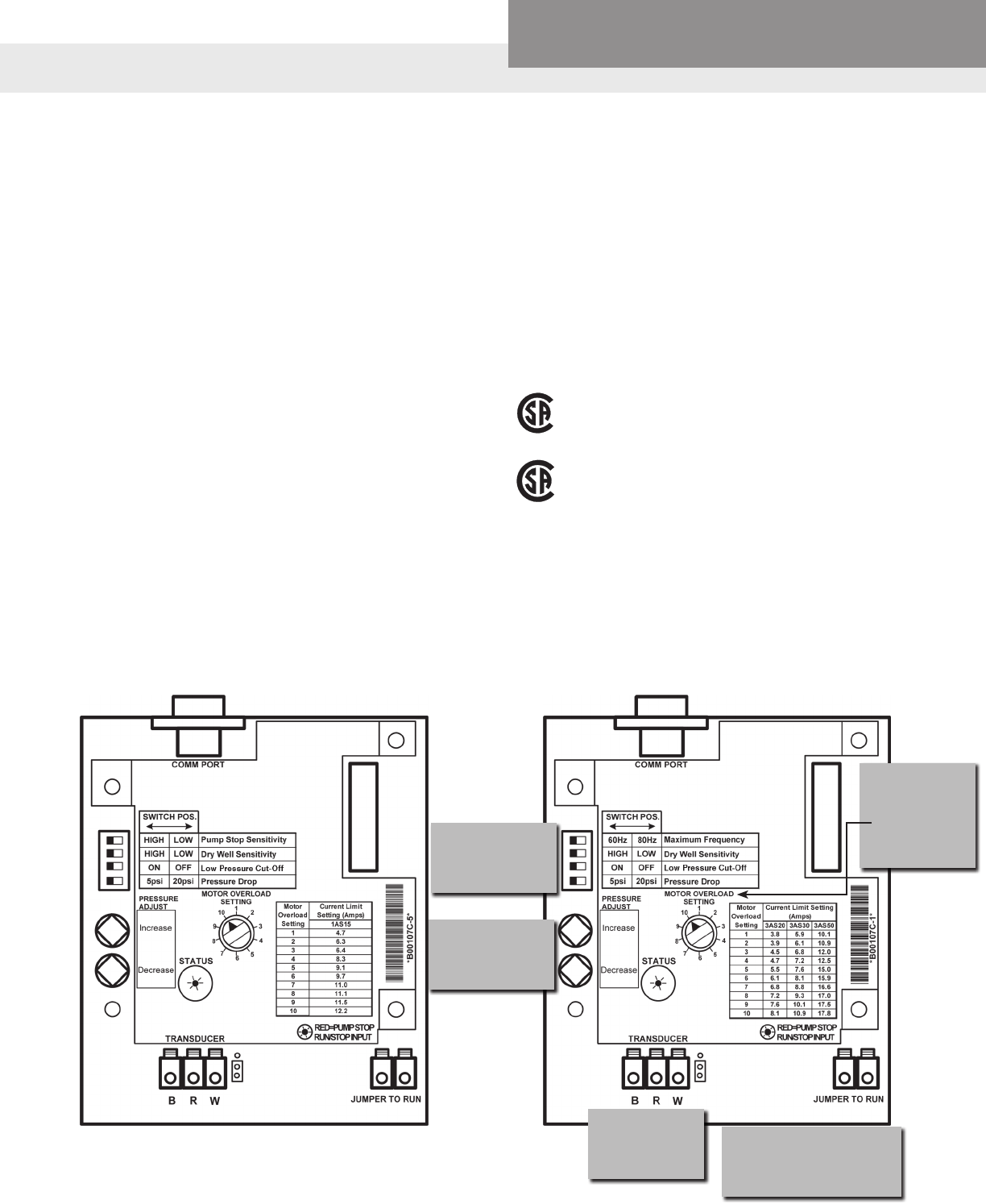
USER INTERFACE BOARD
1AS Controllers 3AS Controllers
Switch Input (Over
Pressure Protection,
Level Control)
Pressure
Transducer
Connection
Drive
Settings /
Protection
Pressure
Adjustment
Current
Limit Dial
(Motor
Overload
Protection)
Residential Water Systems
CentriPro
PAGE 3
Controller Temperature Range:
• Minimum Ambient
Temperature: 14ºF (-10ºC)
• Maximum Ambient
Temperture: 122ºF (50ºC)
Input Voltage: single-phase, 230
Volt, two (2) wire grounded sys-
tem.
Output Voltage: variable frequen-
cy, variable voltage, three-phase
power to the motor.
Speed Selector Switch: Selects
Output Frequency of either –
• 30 - 60 Hz - Use matched
HP Water End and Motor
• 30 - 80 Hz - Use mis-matched
Water End and Motor
Enclosure Dimensions:
• Height: 18.6"
• Width: 9.9"
• Depth: 5.3"
Packaged Dimensions:
• Height: 21"
• Width: 13"
• Depth: 8"
3AS20 SPECIFICATIONS
• HP Range: ¾ to 2
• Unit Weight: 19 lbs.
• Packaged Weight: 23 lbs.
• Pressure Set point adjustable
from 20 - 85 psi using the stan-
dard 100 psi sensor. ➀
3AS30 SPECIFICATIONS
• HP Range: 1½ to 3
• Unit Weight: 20 lbs.
• Packaged Weight: 24 lbs.
• Pressure Set point adjustable
from 20 - 85 psi using the stan-
dard 100 psi sensor. ➀
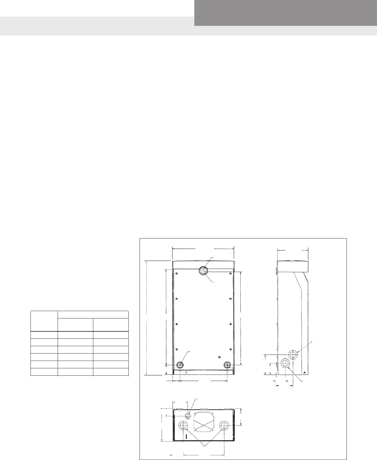
DIMENSIONS (inches) – ALL MODELS
SPECIFICATIONS – 3Ø MODELS / 1Ø INPUT AND 3Ø OUTPUT
3AS50 SPECIFICATIONS
• HP Range: 3 to 5
• Unit Weight: 25 lbs.
• Packaged Weight: 29 lbs.
• Pressure Set point adjustable
from 20 - 100 psi using the
standard 200 psi sensor. ➀
➀ Higher pressures are available using
a higher pressure sensor. See page
4.
9.9 5.3
18.6 15.6 15.2
1.6
1.2 7.50
2X (.28 DIA.)
5.3
1.2
2.4
2.7
1.7 6.5
½" KNOCKOUT
(TRANSDUCER)
½" x 1" KNOCKOUTS
.28 DIA.
.28 DIA.
.50 DIA.
3.3
1.9
1.5
2.7
¾ & 1"
COMBINATION
KNOCKOUTS
BOTH SIDES
Motor Compatibility with
3AS_ _ Models
Three Phase
HP CentriPro & Franklin &
Pentek XE Grundfos
¾ Yes Yes
1 Yes Yes
1½ Yes Yes
2 Yes Yes
3 Yes Yes
5 Yes Yes
½" x 1"
Residential Water Systems
CentriPro
PAGE 4
Controller Temperature Range:
• Minimum Ambient
Temperature: 14ºF (-10ºC)
• Maximum Ambient
Temperture: 122ºF (50ºC)
Input Voltage: single-phase, 230
Volt, two (2) wire grounded system.
Output Voltage: 1Ø, variable volt-
age, variable frequency, single
phase power to the 2-wire or
3-wire motor
Speed/Frequency: 30-60 only
Enclosure Dimensions:
• Height: 18.6"
• Width: 9.9"
• Depth: 5.3"
Packaged Dimensions:
• Height: 21"
• Width: 13"
• Depth: 8"
SPECIFICATIONS – 1AS15 – 1Ø MODEL – 1Ø INPUT AND 1Ø OUTPUT
1AS15 SPECIFICATIONS
• Unit Weight: 19 lbs.
• Packaged Weight: 23 lbs.
• Pressure Set point adjustable
from 20 - 85 psi using the stan-
dard 100 psi transducer.
• HP Range:
Diaphragm Tank Sizing and Pre-Set Pressure
Recommendations:
Diaphragm type (captive air) tanks are required on
these systems.
Table 1: Tank Sizing Selection
Use Total Tank Volume, not drawdown volume, to
select the proper tank size. The total tank volume
should be approximately 20% of the pump’s
maximum ow. For example, when using a 10 gpm
pump the system requires a minimum 2 gallon (total
volume) tank.
The tank sizing recommendations are eld proven to
prevent objectionable pressure drops on start-up and
provide smooth operation for the majority of variable
speed pump systems.
When using the default, 5 PSI pressure drop, setting:
Set the tank pressure, while tank is empty of water, to
20 psi below the desired system pressure setting. Ex.
for a 50 psi system pressure, charge the tank to 30 psi.
See IOM for other settings or if using a large tank.
TANK SIZING
Motor Compatibility with Aquavar SOLO 1AS15
Single Phase 2-Wire Single Phase 3-Wire
HP CentriPro & Franklin & CentriPro & Franklin &
Pentek XE Grundfos Pentek XE Grundfos
½ Yes Yes Yes Yes
¾ Yes Yes Yes Yes
1 Yes Yes Yes Yes
1½ Yes Yes Yes Yes
2 No No Yes ➀
➀ Amps are higher than controller overload range - use of these motors will current limit and provide
reduced performance.
Maximum
Pump GPM
Recommended Tanks
Total Volume Order Number
10 1.9 V6P
24 4.9 V15P
36 7.3 V25P
70 13.9 V45
100 19.9 V60
Residential Water Systems
CentriPro
PAGE 5
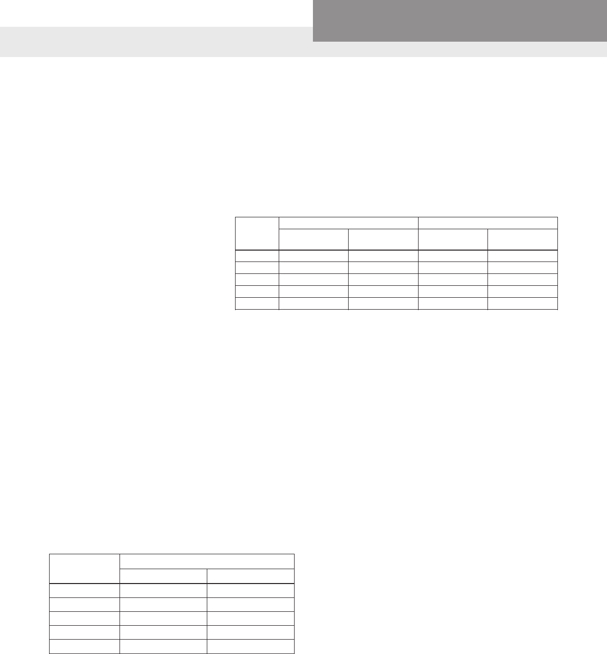
Table 3: Service Factor Amps All Motors
Transducer 1AS15 / 3AS20 3AS30 3AS50
Minimum PSI Maximum PSI Minimum PSI Maximum PSI Minimum PSI Maximum PSI
100 PSI ➀ 20 85 20 85 10 50
200 PSI ➁ 40 170 40 170 20 100
300 PSI 60 255 60 255 30 150
➀ Standard on 1AS15/3AS20, 3AS30 ➁ Standard on 3AS50
Warning! Exploding tank can injure or kill, some combinations of Transducer and Controller allow system pressure adjustment to exceed
the maximum working pressure of the tank and piping.
Ensure system pressure is set below the maximum working pressure of the tank and system piping.
Protect tank and piping against overpressure, install a properly sized pressure relief valve (PRV) able to pass full pump ow at the
maximum working pressure of the tank. In nished basements or where PRV blow-off can cause property damage, pipe the PRV
to a suitable drain.
PRESSURE RANGES FOR ALL AVAILABLE TRANSDUCERS
Motor Controller Model ➁ Circuit Generator ➃
HP Voltage ➀ 1AS15 3AS20 3AS30 3AS50
Breaker ➂ (VA)
½ 230
2200
200
¾ 230
15 2900
200
1 230
3500
200
1½ 230
20 4400
200
2 230
6100
200 30
230
3 200 8100
40
5 230
50 13300
200
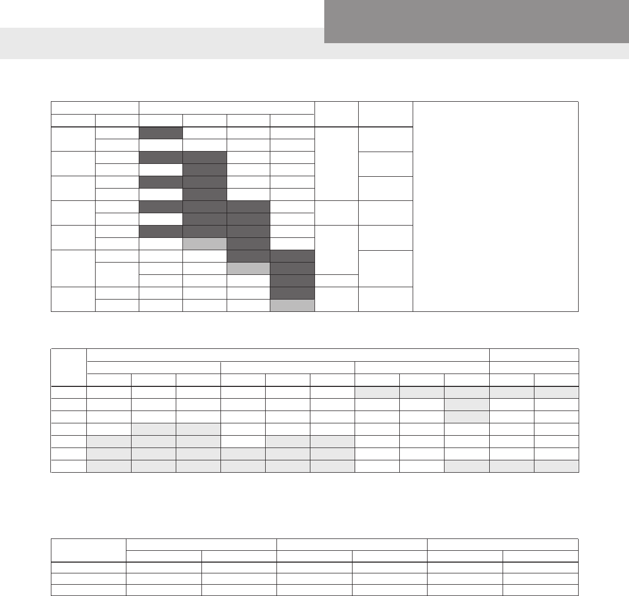
Table 2: Controller, Breaker, Generator Sizing
➀ Supply voltage must be 196
VAC – 265 VAC.
➁ Shaded areas indicate which
controller models can be used
with which motors. Lighter
shading indicates combina-
tions where controller will limit
peak performance to 85% of
catalog value for pump/motor.
➂ Circuit Breaker or Dual Element
Time Delay Fuse Size (Amps)
protecting branch circuit sup-
plying controller.
➃ Minimum size of single phase
240 V generator required.
230 Volt 200 Volt
HP 1Ø 2-Wire 1Ø 3-Wire 3Ø 3Ø
CentriPro1 Franklin Grundfos CentriPro Franklin Grundfos CentriPro Franklin Grundfos CentriPro Franklin
½ 4.7/4.7 6 6 6.3 6 6 N/A N/A N/A N/A N/A
¾ 6.4/6.2 8 8.4 8.3 8 8.4 3.9 3.8 N/A 4.5 4.4
1 9.1/8.1 9.8 9.8 9.7 9.8 9.8 4.7 4.7 N/A 5.5 5.4
1½ 11.0/10.4 13.12 13.12 11.1 11.5 11.6 6.1 5.9 7.3 7.2 6.8
2 N/A N/A N/A 12.2 13.22 13.22 7.6 8.1 8.7 8.8 9.3
3 N/A N/A N/A N/A N/A N/A 10.1 10.9 12.2 12 12.5
5 N/A N/A N/A N/A N/A N/A 17.5 17.8 19.82 20.22 20.52
1. CentriPro 2-Wire motors have Generation 1 and Generation 2 amp ratings, see motor nameplate or motor data sticker that was supplied with motor.
2. Amps are higher than controller overload range - use of these motors will current limit and provide reduced performance.
Residential Water Systems
CentriPro
PAGE 6
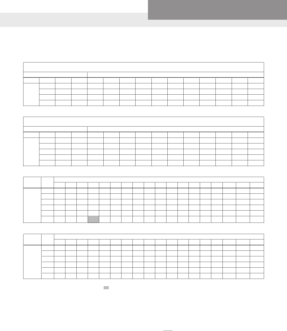
The lengths in each of the Wire Sizing tables represent 100% of the allowable voltage drop when motor is running at full
load. When sizing wire, the voltage drop of each wire segment must be included. The total must not exceed 100% of the al-
lowable drop. Take for example a 1.5 HP motor with a distance from Service Entrance to Controller of 100' and 500' between
the Controller and Motor.
• Service Entrance to Controller = 100' of 10 AWG (100/455) = 22 % (455' is from the S.E. to Controller chart)
• Controller to Motor = 500' of 12 AWG (500/709) = 71 % (709' is from the Controller to Motor chart)
Total Drop (must be ≤ 100%) 93 %
If the distance from the Controller to Motor was 600' (600/709) = 85% + 22% = 107%, we would need to use #10 wire for that
segment, ex. 600/1126 = 53% + 22% (for 100' of #10) = 75% which is acceptable. It is also acceptable to use different wire
sizes for the Buried and Well sections of wire.
All Models – Service Entrance to Controller
Controller Motor Copper Wire Size 75ºC Insulation Exposed to a Maximum of 50ºC (122ºF) Ambient Temperature ②
Input HP 14 12 10 8 6 4 3 2 1 1/0 2/0 3/0 4/0 250 300 350 400 500
¾ 279 445 706 1020 1608 2552 3186 4019 5065 6383 8055
1 226 360 571 824 1300 2064 2576 3250 4095 5161 6513 8201
230V 1½ * 286 455 657 1036 1644 2052 2589 3262 4111 5188 6533 8236 9710
1 PH 2 * * 331 478 754 1197 1495 1886 2376 2995 3779 4759 5999 7073 8455 9852
3 * * 246 355 561 890 1111 1401 1766 2225 2808 3536 4458 5256 6283 7321 8343
5 * * * 218 343 545 680 858 1081 1363 1720 2165 2730 3219 3847 4483 5109 6348
3AS20, 30, 50 Controller to Motor – Controllers with 3Ø Motors
Controller Motor Copper Wire Size 75ºC Insulation Exposed to a Maximum of 50ºC (122ºF) Ambient Temperature ②
Output HP 14 12 10 8 6 4 3 2 1 1/0 2/0 3/0 4/0 250 300 350 400 500
¾ 690 1100 1748 2523 3978 6316 7884 9945
1 558 890 1413 2040 3216 5106 6375 8041
230V 1½ 445 709 1126 1625 2562 4068 5078 6406 8072
3 PH 2 324 516 820 1184 1866 2963 3699 4666 5879 7410 9351
3 241 384 609 880 1387 2202 2749 3467 4369 5506 6949 8750
5 * 235 373 539 849 1348 1683 2123 2675 3372 4255 5358 6755 7964 9520
① Reduce lengths by 13% for 200 V systems. * Wire does not meet the N.E.C. ampacity requirement.
② Lengths in bold require 90º C wire. Shading indicates 40º C maximum ambient.
Table 4: Wire Sizing
Maximum Cable Lengths in Feet to Limit Voltage Drop to 5% for 230 V Systems ①
1AS15 Controller to Motor – Controllers with 2-Wire 1Ø Motors
Motor Lead Lengths - CentriPro 2-Wire Motors -
Based on Service Factor Amps, 30º C Ambient and 5% Voltage Drop
Motor Rating 60º C & 75º C Insulation - AWG Copper Wire Size
Volts HP kW SFA 14 12 10 8 6 4 2 1/0 2/0 3/0 4/0
½ 0.37 4.7 466 742 1183 1874 2915 4648 7379 11733 14803 18688 23544
230 ¾ 0.55 6.4 342 545 869 1376 2141 3413 5419 8617 10871 13724 17290
1 0.75 9.1 241 383 611 968 1506 2400 3811 6060 7646 9652 12160
1½ 1.1 11.0 199 317 505 801 1246 1986 3153 5013 6325 7985 10060
1AS15 Controller to Motor – Controllers with 3-Wire 1Ø Motors
Motor Lead Lengths - CentriPro 3-Wire Motors (CSIR) -
Based on Service Factor Amps, 30º C Ambient and 5% Voltage Drop
Motor Rating 60º C & 75º C Insulation - AWG Copper Wire Size
Volts HP kW SFA 14 12 10 8 6 4 2 1/0 2/0 3/0 4/0
½ 0.37 6.3 348 553 883 1398 2175 3467 5505 8753 11044 13942 17564
¾ 0.55 8.3 264 420 670 1061 1651 2632 4178 6644 8383 10582 13332
230 1 0.75 9.7 226 359 573 908 1413 2252 3575 5685 7173 9055 11408
1½ 1.1 11.1 197 314 501 793 1234 1968 3124 4968 6268 7913 9969
2 1.5 12.2 180 286 456 722 1123 1790 2843 4520 5703 7199 9070
Residential Water Systems
CentriPro
PAGE 7
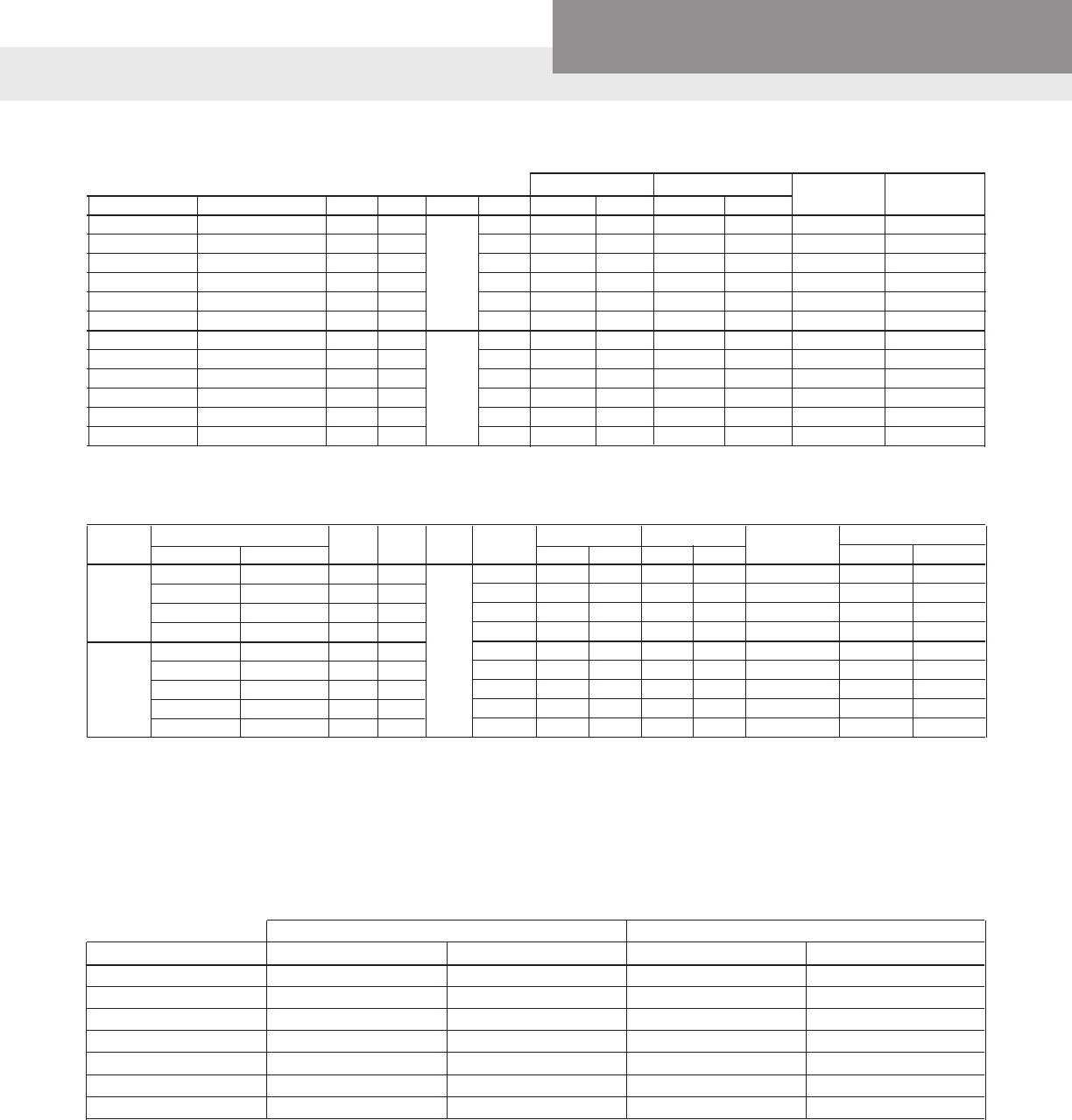
3Ø, 4" MOTORS – ELECTRICAL DATA, 60 HERTZ 3450 RPM
Full Load Service Factor Locked Line - Line
CentriPro # Red Jacket # HP kW Volts SF Amps Watts Amps Watts Rotor Amps Resistance
M07430 75C323 0.75 0.55 1.5 3.8 812 4.5 1140 32 2.6-3.0
M10430 100C323 1 0.75 1.4 4.6 1150 5.5 1500 29 3.4-3.9
M15430 150C323 1.5 1.1 200 1.3 6.3 1560 7.2 1950 40 1.9-2.5
M20430 200C323 2 1.5 1.25 7.5 2015 8.8 2490 51 1.4-2.0
M30430 300C323 3 2.2 1.15 10.9 2890 12.0 3290 71 0.9-1.3
M50430 500C323 5 3.7 1.15 18.3 4850 20.2 5515 113 0.4-0.8
M07432 75C313 0.75 0.55 1.5 3.3 850 3.9 1185 27 3.3-4.3
M10432 100C313 1 0.75 1.4 4.0 1090 4.7 1450 26.1 4.1-5.1
M15432 150C313 1.5 1.1 230 1.3 5.2 1490 6.1 1930 32.4 2.8-3.4
M20432 200C313 2 1.5 1.25 6.5 1990 7.6 2450 44 1.8-2.4
M30432 300C313 3 2.2 1.15 9.2 2880 10.1 3280 58.9 1.3-1.7
M50432 500C313 5 3.7 1.15 15.7 4925 17.5 5650 93 .85-1.25
The AQUAVAR SOLO™ 1AS15 model 30-60 hertz speeds only.
The AQUAVAR SOLO™ 3AS models provide the option of operating the system at either 30-60 or 30-80
hertz speeds.
30 - 60 Hertz (Standard Speed) Setting 30 - 80 Hertz (High Speed) Setting
Controller Water End Motor HP Water End Motor HP
3AS20 1 1 ½ 1
3AS20 1½ 1½ ¾ 1½
3AS20 2 2 1 2
3AS30 1½ 1½ ¾ 1½
3AS30 2 2 1 2
3AS30 3 3 1½ 3
3AS50 5 5 3 5
When using the “80 hertz” setting with mis-matched water ends and motors, use the larger pump curve as the
top curve. The bottom, or 30 hertz, curve is calculated using the smaller wet end curve and the Afnity Laws. The
ProPak Bulletins dene performance curves. See BGPROPAK60 or BGPROPAK80 for curves.
Type Motor Order Number HP KW Volts SF Full Load Service Factor Locked Winding Resistance
CentriPro Red Jacket Amps Watts Amps Watts Rotor Amps Main Start
M05422 50C211 0.5 0.37 1.6 3.7 834 4.7 1073 19.5 4.5-5.2 –
2 Wire M07422 75C211 0.75 0.55 1.5 5.0 1130 6.4 1459 24.8 3.0-4.8 –
PSC M10422 100C211 1.0 0.75 1.4 7.9 1679 9.1 1990 21.7 4.2-5.2 –
M15422 150C211 1.5 1.1 1.3 9.2 2108 11.0 2520 42.0 1.9-2.3 –
M05412 50C311 0.5 0.37 230 1.6 5.5 745 6.3 1033 22.3 4.2-4.9 17.4-18.7
M07412 75C311 0.75 0.55 1.5 7.2 1014 8.3 1381 32.0 2.6-3.6 11.8-13
3 Wire M10412 100C311 1 0.75 1.4 8.4 1267 9.7 1672 41.2 2.2-3.2 11.3-12.3
M15412 150C311 1.5 1.1 1.3 9.7 1693 11.1 2187 47.8 1.6-2.3 7.9-8.7
M20412 200C311 2 1.5 1.25 9.9 2170 12.2 2660 49.4 1.6-2.2 10.8-12.0
1Ø, 4" MOTORS – ELECTRICAL DATA, 60 HERTZ 3450 RPM

Xylem Inc.
2881 East Bayard Street Ext., Suite A
Seneca Falls, NY 13148
Phone: (866) 325-4210
Fax: (888) 322-5877
www.centripro.com
CentriPro and Aquavar SOLO are trademarks of Xylem Inc. or one of its subsidiaries.
© 2012 Xylem Inc. BAQSOLO R3 May 2014
1) The tissue in plants that brings water upward from the roots;
2) a leading global water technology company.
We’re 12,500 people unied in a common purpose: creating innovative solutions
to meet our world’s water needs. Developing new technologies that will improve
the way water is used, conserved, and re-used in the future is central to our work.
We move, treat, analyze, and return water to the environment, and we help people
use water efciently, in their homes, buildings, factories and farms. In more than
150 countries, we have strong, long-standing relationships with customers who
know us for our powerful combination of leading product brands and applications
expertise, backed by a legacy of innovation.
For more information on how Xylem can help you, go to www.xyleminc.com
Xylem
