548320 1 B&G Hydronic Heating And Plumbing Brochure
548319 1 B&G Hydronic Heating And Plumbing Brochure 548319_1_B&G Hydronic Heating and Plumbing Brochure
548318 1 B&G Hydronic Heating And Plumbing Brochure 548318_1_B&G Hydronic Heating and Plumbing Brochure 548318_1_B&G Hydronic Heating and Plumbing Brochure pdf pumpproducts
: Pump 548320 1 B&G Hydronic Heating And Plumbing Brochure 548320_1_B&G Hydronic Heating and Plumbing Brochure pdf
Open the PDF directly: View PDF ![]() .
.
Page Count: 44

A-50R
Hydronic Heating
and Plumbing Products
Service and support from the most
trusted name in the industry – Bell & Gossett®
.
The Bell & Gossett name has always stood for uncompromising quality and dependability. That’s evident
in the way our products are built and backed by our outstanding customer service and support team.
Your local Bell & Gossett representative is available any time and is an experienced professional with
a wealth of technical expertise. In addition to expert system and product application assistance and
a wide product inventory warehoused locally, we offer our award-winning ESP-PLUS® software
selection program.
ESP-PLUS is a special set of Bell & Gossett software that helps you design uid handling systems
accurately, effectively and quickly. You get fast, precise equipment selection, pump performance
curves, automatic calculations of payback and annual operating costs, equipment schedules,
submittals, specications and more. ESP-PLUS includes:
• Bell & Gossett centrifugal pumps, packaged systems, hydronic specialties and heat exchangers
• Domestic® Pump condensate transfer equipment
• Hoffman Specialty® steam specialties

Table of Contents Page Number
Pumps
ecocirc Series Heating/Cooling Circulators ........................................ 4-5
ecocirc XL Series Heating/Cooling Circulators .................................... 6-8
ecocirc e3 Series Potable Water Pumps .............................................. 9
ecocirc wireless Potable Water Kit ....................................................... 10
autocirc Series Potable Water Pumps .................................................. 11
LS Condensate Removal Pump ........................................................... 12
ecocirc SC Solar Pump ..........................................................................13
NRF (Cast Iron, Maintenance-Free Wet Rotor) ............................... 14-15
NBF (Bronze, Maintenance-Free Wet Rotor) .................................. 16-17
SSF (Stainless Steel, Maintenance-Free Wet Rotor) ........................16-17
Series LR™ (Compact Maintenance-Free) ............................................17
Series PL™ (Maintenance-Free Dry Motor) ..........................................18
Three Piece – Oil Lubricated Series 100, HV, PR, 2”, 2-1/2” LD-3,
HD-3, PD-35, PD-37, PD-38, PD-40 ................................................19
Series 60 (In-Line Mounted) ...........................................................20-21
Pump Accessories
Check-Trol™ Isolation Flow Control Flange .........................................22
Isolation and Companion Flanges .......................................................23
Controls
ecocirc Series Timer ............................................................................. 24
NBF Aquastats and Timer .................................................................... 24
Relays
AZ-1A Snap-On Pump Control ............................................................. 25
ZONETROL™ Switching Relays ............................................................ 26
Valves
Snap Zone Valve .................................................................................. 27
Circuit Setter® Plus ............................................................................. 28
Circuit Sentry™ Flo-Setter™ ................................................................29
Flow Control Valves Flo-ControlTM ........................................................ 30
Flow Control Valves HydrotrolTM ........................................................... 31
Differential Bypass Valves ................................................................... 31
Pressure Reducing Valves ................................................................... 32
ASME Safety Relief Valves .................................................................. 32
Monoflo® Fittings ............................................................................... 33
Air Separators
IAS (Inline Air Separators) ................................................................... 33
EAS (Enhanced Air Separator) ............................................................. 34
EASB-JR (Enhanced Air Separator) ...................................................... 34
Hydronic Specialties
Air Vents ..............................................................................................35
Vacuum Breaker .................................................................................. 35
Drain-O-Tank® Air Charger ................................................................. 35
Thermoflo® Balancer .......................................................................... 35
Primary/Secondary Header ..................................................................36
Tanks
HFT Pre-Charged Hydronic Heating Tanks ........................................... 37
Plain Steel Compression Tanks ........................................................... 37
ATF (Airtrol® Tank Fittings) .................................................................. 37
PT Diaphragm Tanks ........................................................................... 38
WTX Diaphragm Tanks ........................................................................ 38
Tank Purge Valves ............................................................................... 39
Heat Exchangers
Brazed Plate Heat Exchangers ...................................................... 40-41
Wastewater Pumps
Submersible Sump Pumps - SC, SCS, SS, BSP, BBSP, 2WT........... 42-43
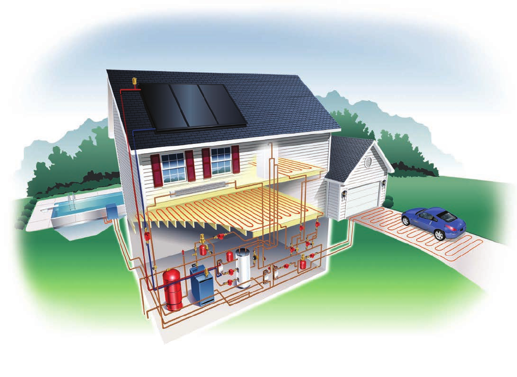
The Most Complete Line
of Hydronic Heating and
Plumbing Products.
All from a Single Source – Bell & Gossett.
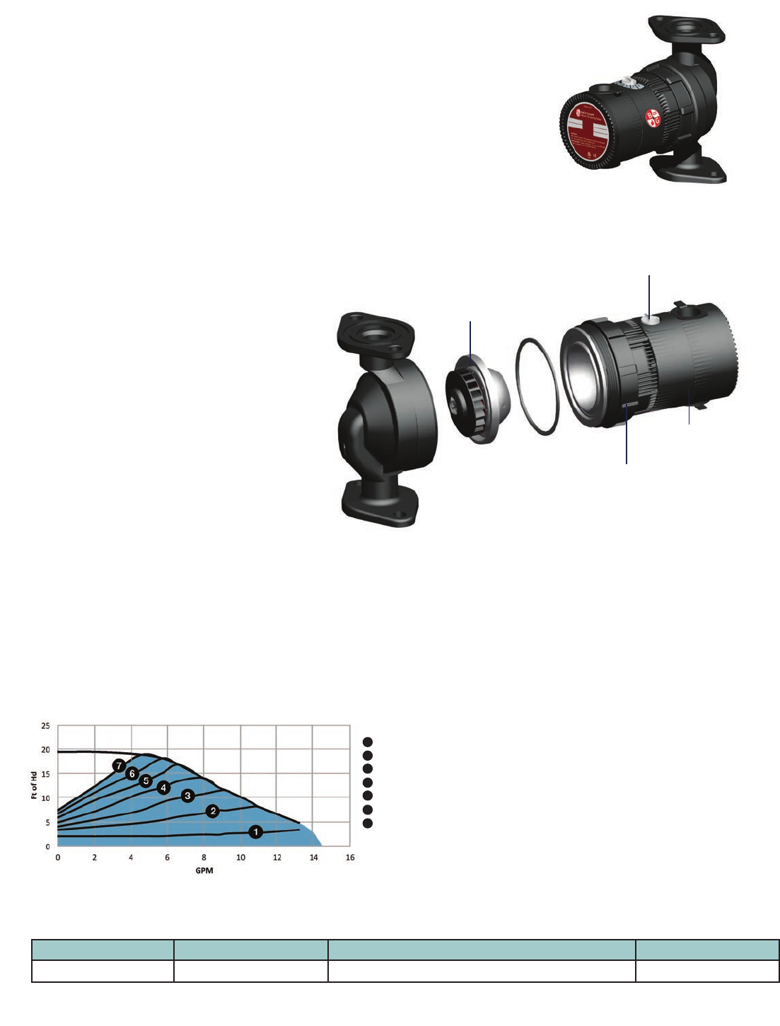
CIRCULATORS ecocirc® auto
Heating/Cooling Circulator
4
High efciency
ECM motor
Step-less speed dial with LED for
pump status and troubleshooting
Magnetically centered
spherical impeller/rotor
Model Number Part Number Control Mode Shipping Weight
ecocirc 19-14 auto 6050B2000 auto – Proportional Pressure 9.25 lb
Description
ecocirc 19-14 auto are designed, with highly efcient electronically commutated
permanent magnet motor (ECM/PM Technology), specically for hydronic systems.
Ideal for hydronic systems with zone or thermostatic valves, the ecocirc 19-14 auto can
be used as replacements for existing circulators with induction motors as well as new
construction as primary or zone circulators.
The ecocirc 19-14 auto has a proportional pressure control logic, which allows the pump to
slow down automatically as it approaches shut off condition (as the valve closes) then ramp
up when the demand increases (as the valve opens).
It includes a step-less dial to adjust the speed to meet the system requirements.
Materials of Construction
Pump Body: Cast Iron
O-Ring: EPDM
Bearing: Carbon/Alumina Ceramic
Impeller: Nylon/PPO
Motor: High Efciency ECM/PM
All Other Wetted Parts: Stainless Steel
Operating Data
Maximum Working Pressure: 150 PSI (10 Bar)
Maximum Working Temperature: 203°F (95°C)
Minimum Working Temperature: 40°F (4°C)
Motor
ECM/PM Spherical Motor
115 Volts, 60 HZ, 1 Phase
60 Watts Max Power Consumption
Automatic Overload Protection
Low in-rush current
Piping Connection
Flanged, 2-Bolt
For use with ¾, 1, 1¼, or 1½ inch pipe
auto
Setting 1
Setting 2
Setting 3
Setting 4
Setting 5
Setting 6
Setting 7
1
2
3
4
5
6
7
auto pump curves
Built-in Software Protection (for auto and vario)
ecocirc 19-14 has built-in protection to protect from installation
errors and improper usage.
There is an overload protection to protect the electronics from
over-current or over-voltage input. To further protect the electronics
from damage, there is an over-temperature protection. This built-in
protection will rst slow the speed down to continue operation, but
will shut down if the temperature of the electronics continues to rise
to high levels.
The circulator is also protected against dry-run condition. Built-in
software will recognize a change in performance and determine that
the circulator is dry-running. Automatically the circulator will stop
operating and will need to be reset to continue operation.
The circulator continually monitors the system for any change in
power input or dry-run condition or electronic’s temperature. If any
error is detected, the circulator will shut down and will need to be
reset to continue operation after the error has been xed.
Always easy to access. The screw ring design
results in a pump motor that can be rotated in
any position around the 360° circle. Therefore the
electrical connection as well as the control dial is
easy to access.
vario
6.5” (65mm)
4.97” (126.1mm)
6.05” (153.6mm)
7.46” (189.6mm)
Materials of Construction
Pump Body: Cast Iron
O-Ring: EPDM
Bearing: Carbon/Alumina Ceramic
Impeller: Nylon/PPO
Motor: High Efciency ECM/PM
All Other Wetted Parts: Stainless Steel
Operating Data
Maximum Working Pressure: 150 PSI (10 Bar)
Maximum Working Temperature: 203°F (95°C)
Minimum Working Temperature: 40°F (4°C)
Motor
ECM/PM Spherical Motor
115 Volts, 60 HZ, 1 Phase
60 Watts Max Power Consumption
Automatic Overload Protection
Low in-rush current
Piping Connection
Flanged, 2-Bolt
For use with ¾, 1, 1¼, or 1½ inch pipe
5
4.17” (106mm)
2.68” (68mm)
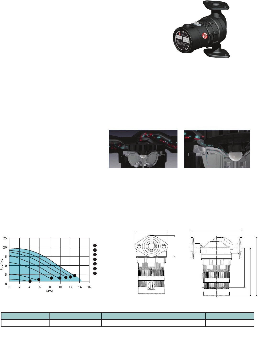
CIRCULATORS ecocirc® vario
Heating/Cooling Circulator
Model Number Part Number Control Mode Shipping Weight
ecocirc 19-14 vario 6050B2001 vario – Constant Curve 9.25 lb
vario pump curves
1
6
5
4
3
2
7
vario Pump Curves
Setting 1
Setting 2
Setting 3
Setting 4
Setting 5
Setting 6
Setting 7
1
2
3
4
5
6
7
Our design separates the magnetic chamber from the ow
(for auto and vario)
Magnetite and sludge, which are both found in the pumped liquid and are both
magnetic, can accumulate at the permanent magnetic parts of a high efciency
pump, and therefore block and damage it. The Anti-Block Technology separates the
main ow of the pumped media completely from the permanent magnetic parts.
It is virtually impossible for the ecocirc auto or vario to block-up even in an old
open system.
The main ow of the pumped media
(blue) and its magnetite and sludge
particles (red) ow outside the inuence
area of the permanent magnet rotor
(bottom).
The side ow of the wet running
circulators, which is required for
lubrication and cooling of the bearing,
is separated from the main ow with its
magnetite and sludge.
Description
ecocirc 19-14 vario circulators are designed, with highly efcient electronically
commutated permanent magnet motor (ECM/PM technology), specially for
hydronic systems.
The ecocirc 19-14 vario has a constant curve control, which allows the pump to
follow the natural hydraulic curve of a circulator. Basically acts the same as a
standard 3-speed pump except with a step-less dial resulting in innite
speed control.
ecocirc 19-14 vario is ideal for replacement for existing circulators with induction
motors as well as new construction as primary or zone circulators.
Dimension (for auto and vario)
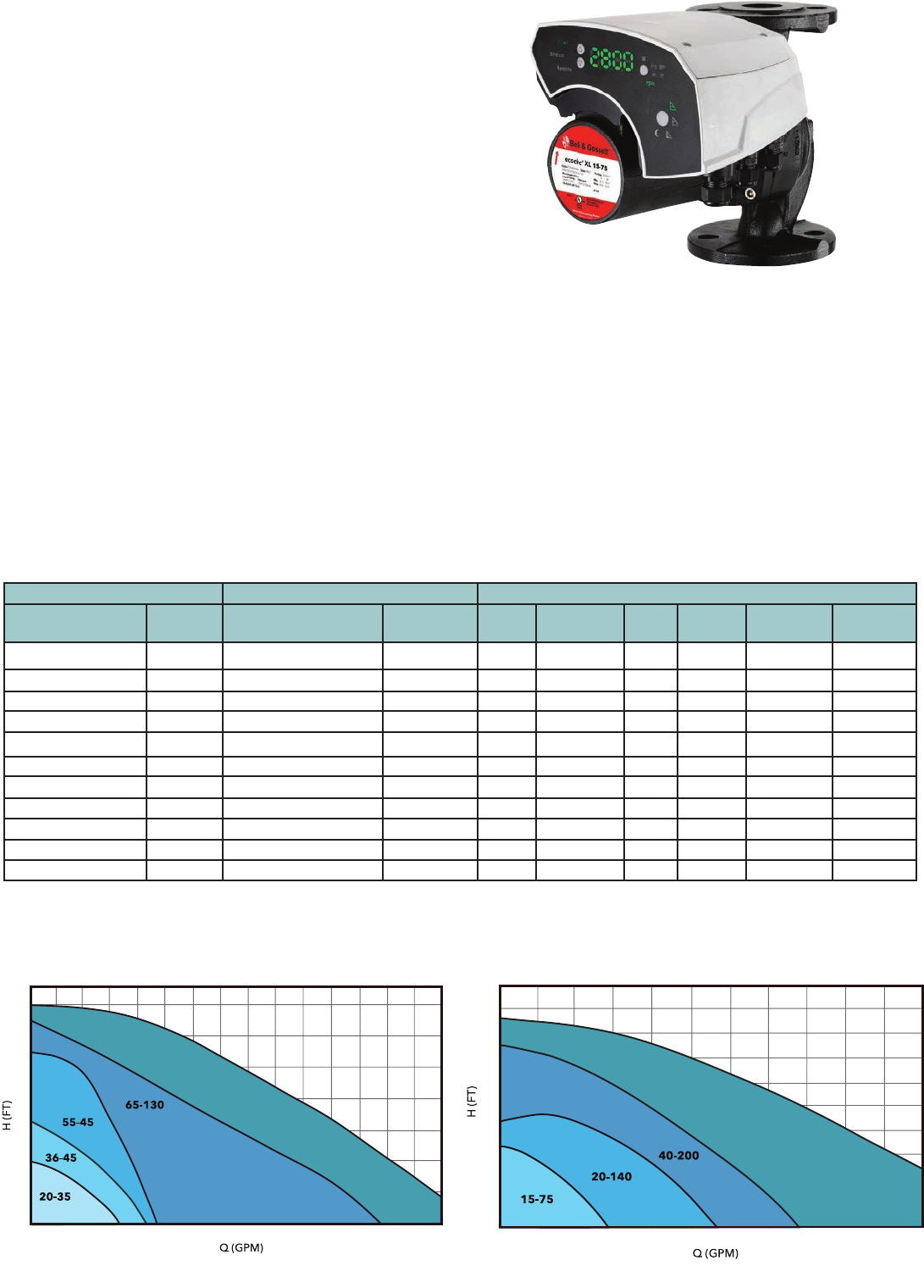
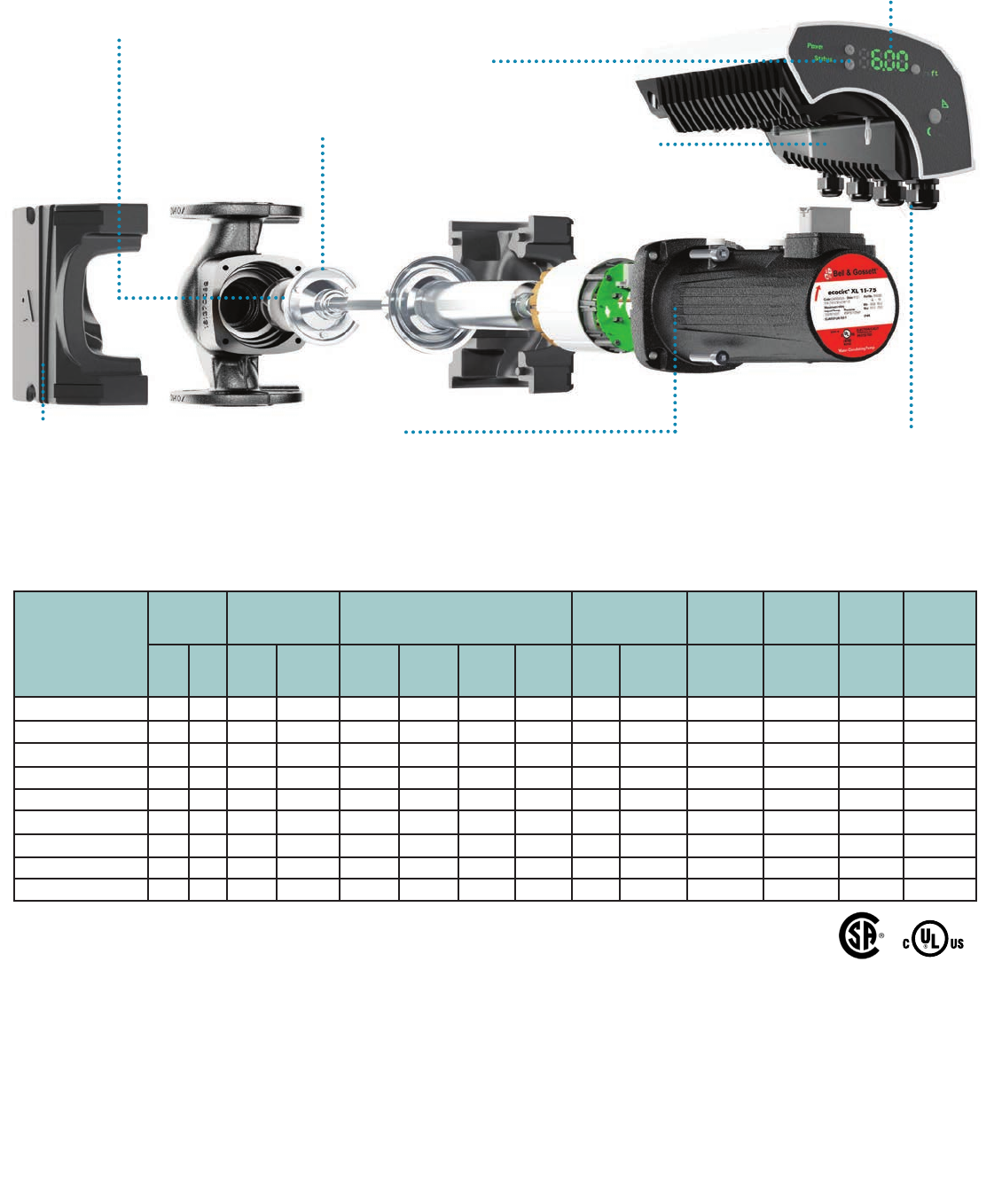
CIRCULATORS ecocirc® XL
High efciency large wet rotor pump for heating,
cooling and potable water systems
6
Description
The ecocirc XL is a high efciency, variable speed, wet rotor pump with
integrated drive. The circulator is available in cast iron or lead-free bronze and
has a broad operating temperature range of 14°F to 230°F (-10°C to 110°C).
The ecocirc XL is suitable for both hot and chilled water systems.
The ecocirc XL circulator is designed with a highly efcient electronically
commutated permanent magnet motor (ECM/PM Technology). This circulator
can enhance hydronics systems with superior quality and dependability. State-
of-the-art hydraulics, advanced motor design, intelligent controls, and smart
communication capabilities highlight expert engineering across a board range
of HVAC and plumbing applications.
Materials of Construction
Pump Body: Cast Iron or Lead-Free* Bronze
Impeller: Poly-phenylene Sulde or Stainless Steel
Shaft: AISI 420 Stainless Steel
Rotor: Permanent Magnet
Bearing: Carbon Sleeve
Gasket/O-Ring: EPDM
All Other Wetted Parts: AISI 304 Stainless Steel
Motor Type: Electronically Commutated Motor /Permanent Magnet
Motor Insulation Class: F
Operating Data
Maximum Working Pressure: 175 PSI (12 Bar)
Minimum Working Temperature: 14°F (-10°C)
Maximum Working Temperature: 230°F (110°C)
Ambient Temperature Range: 32°F - 104°F (0°C - 40°C)
Safety Standards And Protection
• Enclosure: Class 2, IP44 (equivalent to NEMA Type 2)
• UL Listed to UL 778; UL 1004-1, 1004-7; and UL 60730-1
• cUL Listed to C22.2 #108
• Electronically Thermally Protected (Integrated Motor Protection)
• Motor Insulation Class: F
• CSA certied to NSF/ANSI 372 that product contains less than
0.25% lead content by weight on wetted surface
ecocirc XL High Head Performance Range ecocirc XL High Flow Performance Range
Note: Where potable water is pumped, use a lead-free bronze booster. ecocirc XL pumps are recommended for indoor use only.
*CSA certied to NSF/ANSI 372 that product contains less than 0.25% lead content by weight on wetted surface.
** Nominal HP
Cast Iron Body Lead-Free Bronze Body* Rated Motor Characteristics
Model Number Part
Number Model Number Part
Number HP** Voltage Phase Hz Watts Range AMP Range
ecocirc XL 20-35 104300 ecocirc XL B 20-35 104400LF 1/12 115 1 50/60 6-85 0.1 – 1.3
ecocirc XL 36-45 104301 ecocirc XL B 36-45 104401LF 1/6 115 1 50/60 20-200 0.1 – 3.0
ecocirc XL 36-45 104302 ecocirc XL B 36-45 104402LF 1/6 208-230 1 50/60 20-200 0.1 – 1.5
ecocirc XL 15-75 104303 ecocirc XL B 15-75 104403LF 1/6 115 1 50/60 30-150 0.1 – 2.3
ecocirc XL 15-75 104304 ecocirc XL B 15-75 104404LF 1/6 208-230 1 50/60 30-150 0.1 – 1.1
ecocirc XL 55-45 104306 ecocirc XL B 55-45 104406LF 1/2 208-230 1 50/60 30-500 0.2 – 2.0
ecocirc XL 20-140 104308 ecocirc XL B 20-140 104408LF 1/2 208-230 1 50/60 35-470 0.2 – 2.0
ecocirc XL 65-130 104309 ecocirc XL B 65-130 104409LF 1 208-230 1 50/60 45 - 825 0.5 – 3.5
ecocirc XL 40-200 104312 ecocirc XL B 40-200 104412LF 1 208-230 1 50/60 50 - 825 0.5 – 3.5
ecocirc XL 70-145 104315 ecocirc XL B 70-145 104415LF 2 208-230 1 50/60 55 - 1400 0.6 – 6.0
ecocirc XL 40-275 104318 ecocirc XL B 40-275 104418LF 2 208-230 1 50/60 50 - 1400 0.5 – 6.0
75
70
65
60
55
50
45
40
35
30
25
20
15
10
5
0
70-145
0 10 20 30 40 50 60 70 80 90 100 110 120 130 140 150
50
45
40
35
30
25
20
15
10
5
0
0 25 50 75 100 125 150 175 200 225 250 275
40-275
CIRCULATORS ecocirc® XL
High efciency large wet rotor pump for heating, cooling and potable water systems
7
Product Range Chart
Model Number
Version Power Supply Flange Connection Pump Body Fluid
Temp.
Range
Ambient
Temp.
Range
Max.
Pressure
Range
Protection
Class
High
Head
High
Flow
Single
Phase
115V
Single
Phase
208-230V
Small
Booster
(2 Bolts)
Large
Booster
(2 Bolts)
2”
Booster
(4 Bolts)
3”
Booster
(4 Bolts)
Cast
Iron
Lead-Free
Bronze* 14ºF - 230ºF 32ºF - 104ºF 175 PSI IP44
ecocirc XL 20-35 • • • • • • • • •
ecocirc XL 36-45 • • • • • • • • • •
ecocirc XL 15-75 • • • • • • • • • •
ecocirc XL 55-45 • • • • • • • • •
ecocirc XL 20-140 • • • • • • • • •
ecocirc XL 65-130 • • • • • • • • •
ecocirc XL 40-200 • • • • • • • • •
ecocirc XL 70-145 • • • • • • • • •
ecocirc XL 40-275 • • • • • • • • •
*CSA certied to NSF/ANSI 372 that product contains less than 0.25% lead content by weight on wetted surface.
• Small Booster (2 bolts) has a bolt hole to bolt hole dimension of 3-3/16”.
• Large Booster (2 bolts) has a bolt hole to bolt hole dimension of 3-7/16”.
High visibility
Even in dark mechanical rooms, a
bright display with large gures
and symbols makes it easy to view
pump status.
User-friendly interface
With only four logically placed buttons on
an intuitive interface, it’s easy to set and
operate the new ecocirc XL. Advanced
settings enable custom programming,
accessible via a PC, smartphone or wireless
enabled device.
Sensorless technology
The ecocirc XL variable speed drive has the pump’s hydraulic
performance mapped in memory for multiple RPMs with
corresponding electric current values (similar to the ITSC Sensorless
VS Drive). The Delta P value associated with the pump’s actual
operating point is compared to the setpoint Delta P and the
controller makes speed adjustments using current to minimize
the differences between actual Delta P and setpoint Delta P.
Chilled water applications
Electronics are separated from the pump
to prevent condensation for worry free
operation even at 14ºF (-10ºC).
Increase your control options
Multiple inputs including start-stop,
temperature control, pressure regulation
and advanced Modbus or BACnet
control provide dynamic system
management.
Economical operation
A highly efcient ECM motor
combined with optimized pump
hydraulics, keeps operational
costs at a minimum.
Keep it hot or cold
A closed, perfectly molded
insulation shell preserves a
constant temperature of the
pumped liquid.
Input Signals
• One 0-10V (Analog): Speed Control by external controller
• One 4-20mA (Analog): Connection with an external differential pressure
sensor for the pressure control mode (two different pressure sensor
range: 0-15 PSI PN: 104503 and 0-30 PSI PN: 104504
• One external temperature sensor input for either Constant Temperature
or Temperature Inuenced modes. Sensor PN: 104502
• One built-in temperature sensor for either Constant Temperature or
Temperature Inuenced modes.
Remote Building Management System Capabilities
• The pump can be monitored or controlled by a signal from a BMS
(Building Management System). Built-in protocols are BACnet and
Modbus. Direct connection to a PC is available.
• An optional wireless module can be added to create a short range
wireless eld for remote connection to the pump. An internet browser
or an App can be used to program the advanced settings.
Module PN: 104500
NSF/ANSI 372
Self-ushing membrane
Allows clean water to cool and
lubricate the motor bearing.
Restricts entry of abrasive
particles.
CIRCULATORS ecocirc® XL
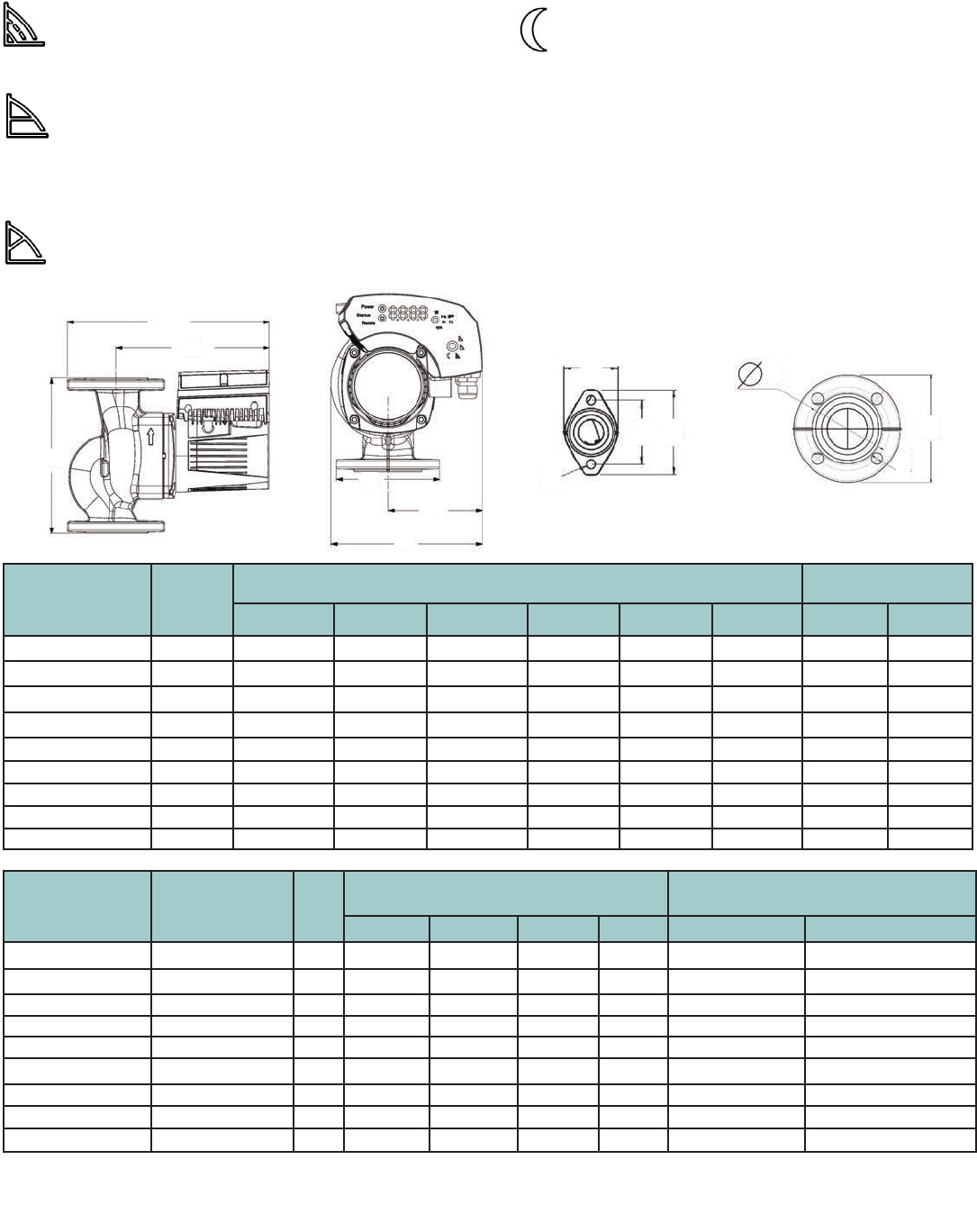
High efciency large wet rotor pump for heating, cooling and potable water systems
Model Number Nominal
Motor HP
Dimenstions - Inches (mm) Approx. Shipping
Weight Lbs. (kg)
A B C D E F Cast Iron Bronze
ecocirc XL 20-35 1/12 9.94 (252) 6.38 (162) 8.20 (208) 4.19 (106) 7.20 (183) 4.72 (120) 19.8 (9) 22 (10)
ecocirc XL 36-45 1/6 9.94 (252) 6.38 (162) 8.20 (208) 4.19 (106) 7.20 (183) 4.72 (120) 19.8 (9) 22 (10)
ecocirc XL 15-75 1/6 11.04 (280) 8.5 (216) 8.39 (213) 5.19 (132) 7.57 (192) 4.72 (120) 26.4 (12) 28.6 (13)
ecocirc XL 55-45 1/2 11.89 (302) 6.38 (162) 10.18 (258) 4.19 (106) 8.12 (206) 5.02 (127) 26.4 (12) 28.6 (13)
ecocirc XL 20-140 1/2 13.39 (340) 11.5 (292) 10.41 (264) 5.19 (132) 8.20 (208) 5.02 (127) 35.2 (16) 39.6 (18)
ecocirc XL 65-130 1 14.84 (377) 11.5 (292) 11.80 (299) 4.62 (117) 9.53 (242) 5.77 (146) 39.6 (18) 44 (20)
ecocirc XL 40-200 1 15.17 (385) 11.5 (292) 11.80 (299) 5.19 (132) 9.53 (242) 5.77 (146) 41.8 (19) 46.2 (21)
ecocirc XL 70-145 2 14.84 (377) 11.5 (292) 11.80 (299) 4.62 (117) 9.53 (242) 5.77 (146) 38.4 (17) 44 (20)
ecocirc XL 40-275 2 16.04 (407) 12.0 (305) 12.57 (319) 6.00 (152) 10.07 (256) 5.77 (146) 49.6 (23) 55 (25)
Model Number Flange Size
Inches - NPT
# of
Bolts
Dimenstions - Inches (mm) B&G Companion Fange
(Set of 2)
G H J K Cast Iron PN Bronze PN
ecocirc XL 20-35 3/4, 1, 1-1/4, 1-1/2 2 4.19 (106) 3.16 (80) 2.62 (66) 0.47 (12) 101001 - 101004* 101011LF - 101014LF*
ecocirc XL 36-45 3/4, 1, 1-1/4, 1-1/2 2 4.19 (106) 3.16 (80) 2.62 (66) 0.47 (12) 101001 - 101004* 101011LF - 101014LF*
ecocirc XL 15-75 2 4 5.18 (132) 4.06 (103) - 0.56 (14) 101215 10216LF
ecocirc XL 55-45 3/4, 1, 1-1/4, 1-1/2 2 4.19 (106) 3.16 (80) 2.62 (66) 0.47 (12) 101001 - 101004* 101011LF - 101014LF*
ecocirc XL 20-140 2 4 5.19 (132) 4.06 (103) - 0.56 (14) 101215 10216LF
ecocirc XL 65-130 1, 1-1/4, 1-1/2 2 4.62 (117) 3.44 (87) 2.86 (73) 0.47 (12) 101005 - 101007* 101015LF - 101017LF*
ecocirc XL 40-200 2 4 5.19 (132) 4.06 (103) 4.06 (103) 0.56 (14) 101215 10216LF
ecocirc XL 70-145 1, 1-1/4, 1-1/2 2 4.62 (117) 3.44 (87) 2.86 (73) 0.47 (12) 101005 - 101007* 101015LF - 101017LF*
ecocirc XL 40-275 3 4 6.00 (152) 5.06 (129) - 0.53 (13) 101217 10218LF
* Part numbers represent a Master Carton of 12 anges with fasteners pack.
1-1/2” is the diameter of the suction and discharge for the 2-bolt models.
STANDARD OPERATING MODES
Constant Speed
The pump maintains a constant speed at any ow rate. The desired
speed is set on the interface panel of the pump.
Constant Pressure (Δp-c)
The pump maintains a constant differential pressure at any ow
demand until the maximum speed is reached. The desired head of
the pump can be set via user interface. Recommended for use in
systems with small or constant pressure losses.
Proportional Pressure (Δp-v)
The differential pressure continuously increases or deceases based
on the ow demand. The set point head can be set on the pump
user interface. Use for systems with large pressure losses.
8
A
B
C
D
F
E
K
J
HGG
H
K
Night Mode
The pump will automatically reduce speed when there is
an abrupt change in uid temperature. The change in uid
temperature is from a boiler operating in night time setback
mode. The built-in temperature sensor is used. (Fixed Speed,
Constant Pressure, Proportional Pressure)
CONSTANT TEMPERATURE SPEED CONTROL
T- Constant Control
This control mode will use a PI algorithm to vary the speed of the pump
in order to maintain a constant temperature of the uid media.
ΔT-Constant Control
This control mode will use a PI algorithm to vary the speed of the pump
in order to maintain a constant differential temperature between the
built-in temperature sensor and external temperature sensor.
9
CIRCULATORS ecocirc® Series
Potable Hot Water Recirculation Pumps - Whole House
e3 – 4, e3 – 6
2 3/4” 4 1/4”
5 1/2”
5 1/2”
UltraCirc Pump Housing
(Union with Ball & Check Valve)
Standard Pump Housing
(Sweat & Threaded)
4 3/16”
2 3/4”
1/2”
2 1/2”
Description
e3 circulators are energy ef cient circulators using permanent magnet, ECM (electronically
commutated motor) technology. The e3 circulators are designed speci cally for potable
water applications. These circulators are lead-free* and come with a variety of options
including a temperature sensor, various body styles, assembled with electrical cord and
plug. Timer sold as an accessory (See page 24 for more information).
Materials of Construction
Pump Body: Lead-Free* Brass
O-Ring: EPDM or Viton
Bearing: Carbon/Alumina Ceramic
Impeller: Nylon/PPO
Motor: High Ef ciency ECM
All Other Wetted Parts: Type 316 Stainless Steel,
Shaft-less and seal-less construction
Operating Data
Pump
Maximum Working Pressure: 150 PSI (10.3 Bar)
Maximum Working Temperature: 203°F (95°C)
Minimum Working Temperature: 50°F (10°C)
Motor
ECM Spherical Motor
10-28 Watts Power Consumption
Automatic Overload Protection
Low in-rush current
Adjustable Speed Switch
(Models Without Temp Sensor)
In nitely variable-speed switch to manually
adjust motor speed.
Adjustable Temperature Sensor
(Fixed Speed Only)
Adjustable Set Point from 68°F to 158°F
(20°C to 70°C)
Turns circulator OFF when water temperature
reaches set point
Turns circulator ON when water temperature is
10°F (6°C) below set point
Connections
1/2” UltraCirc with Ball & Check Valve
1/2” Sweat
1/2” FNPT Threaded
*CSA certi ed to NSF/ANSI 372 that product contains less than 0.25% lead content by weight on wetted surface.
e3 Timer
(See Page 20)
Model
Number
Part
Number Materials Connection Adjustable
Speed
Adjustable
Thermostat Plug
Size Type
e3-4V/BSPYZ LHB08100101 Lead-Free Brass 1/2” Sweat • •
e3-4_/BSXRZ LHB08100102 Lead-Free Brass 1/2” Sweat •
e3-4V/BTXYZ LHB08100104 Lead-Free Brass 1/2” FNPT •
e3-4_/BTPRZ LHB08100106 Lead-Free Brass 1/2” FNPT • •
e3-6V/BSPYZ LHB08100109 Lead-Free Brass 1/2” Sweat • •
e3-6V/BTXYZ LHB08100112 Lead-Free Brass 1/2” FNPT •
e3-6V/BTPYZ LHB08100110 Lead-Free Brass 1/2” FNPT • •
e3-4V/BUPYZ 6050B5002 Lead-Free Brass 1/2” Union • •
e3-4_/BUPRZ 6050B5003 Lead-Free Brass 1/2” Union • •
e3-6V/BUPYZ 6050B5004 Lead-Free Brass 1/2” Union • •
e3-6_/BSPRZ 6050B5006 Lead-Free Brass 1/2” Union • •
e3-Timer LHB08260002 - - -
---- UltraCirc Housing Energy Consumption
---- NPT/Sweat Housing Energy Consumption
UltraCirc Housing Flow
NPT/Sweat Housing Flow
0123456 0123456
30
25
20
15
10
5
0
12
10
8
6
4
2
0
12
10
8
6
4
2
0
6
5
4
3
2
1
0
Flow (GPM) Flow (GPM)
Head (ft)
Head (ft)
Power Consumption (W)
Power Consumption (W)
e3 - 4 Pump Curves e3 - 6 Pump Curves
Pump Curves
The system can be controlled using
the timer and/or the built in thermostat
and has the option for a wireless push
button start.
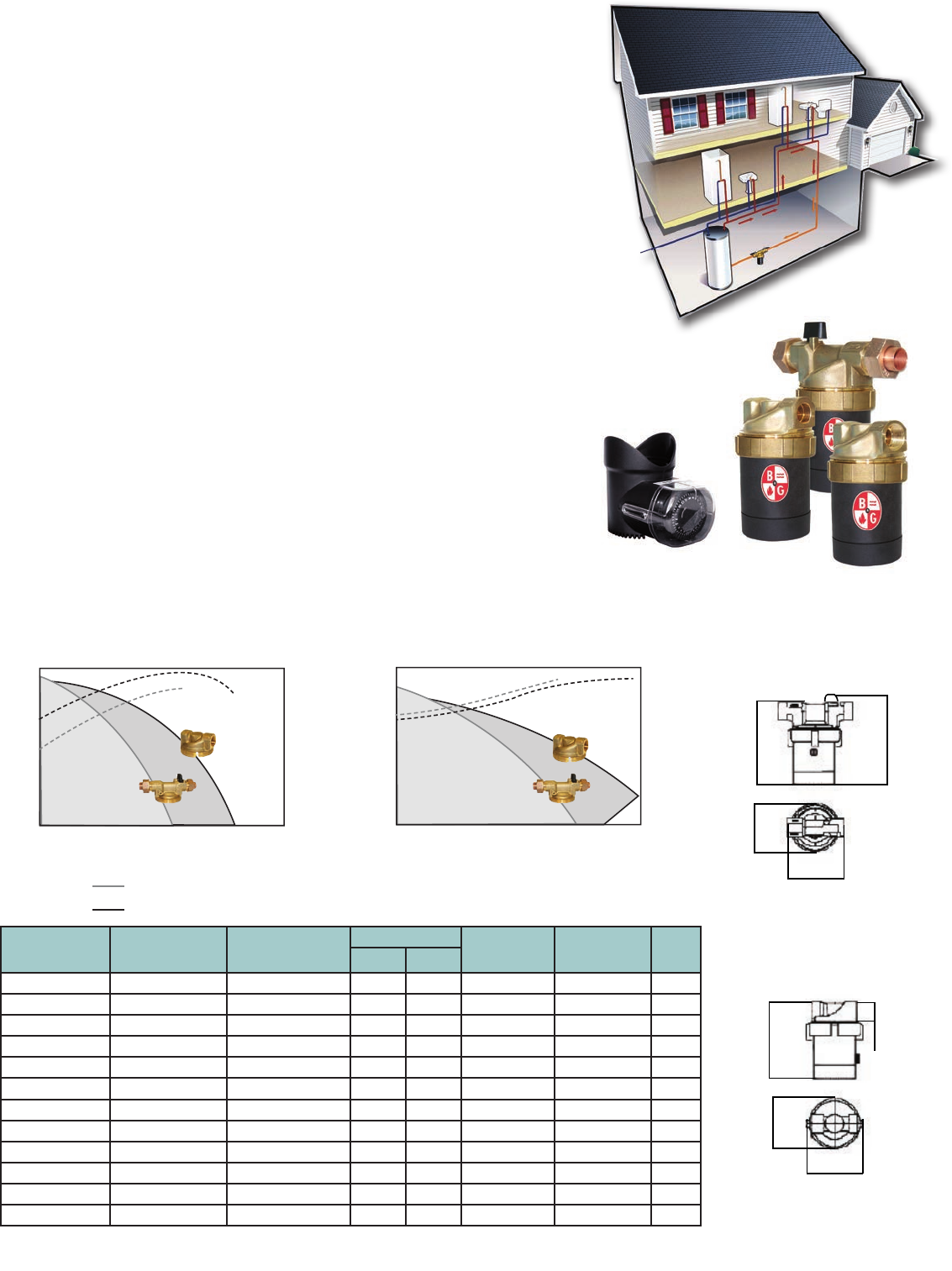
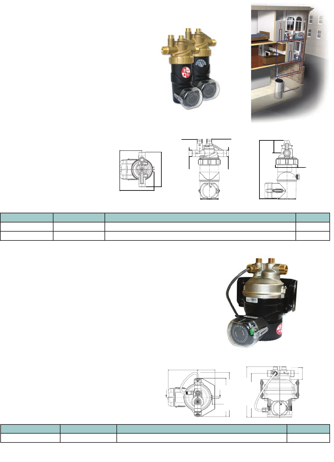
water
heater
hot water
cold water
Optional push
button/signal repeater
(not included in kit).
Can be plugged into
any standard electrical
outlet in the house.
ecocirc
recirculation
pump
paired
mixing
valve
CIRCULATORS ecocirc® wireless
Potable Hot Water Recirculation Kit
10
Description
The ecocirc wireless is a potable hot water recirculation kit (a pump and valve
combination) for instant supply of hot water supply throughout the entire house.
The ecocirc pump is installed on the supply side of the hot water source and the
mixing valve under the sink farthest away from the hot water source. The pump
and valve are in constant wireless communication.
How it Works
The desired water temperature at the valve is set directly on the pump with the
thermostat dial. The water temperature is constantly checked by the valve and the
temperature values are sent to the pump. At approximately 5°F below the desired
water temperature, the pump will begin to circulate hot water. This circulation will
open the valve for hot water to cross into the cold water line, which creates a return
loop back to the hot water source. When the desired temperature is reached, the
pump will stop circulating. This is to prevent continuous circulation.
An Optional Push Button / Signal Repeater
A wireless device to provide instant hot water with a push of a button. The push button
device will override the timer operation and activate the pump to circulate hot water
until the desired temperature is met at the valve. This device also functions as a signal
repeater when the pump and valve have a weak signal due to distance or interference.
Model Number Part Number Connection
Dimension Inches (mm) Shipping
WT.
LBS. (kg)
A B C D E F G W X Y Z
ecocirc wireless
Recirculation Kit 6050B4000 Pump: 3/4” M/F NPT
Valve: 1/2” MNPT x
3/8” compression
4.84
(123)
6.87
(174.6)
4.47
(113.5)
1.97
(50.1)
2.93
(74.4)
4.74
(120.5)
2.68
(68)
3.5
(89)
1.1
(28)
0.87
(22)
5.45
(138.5)
3.9
(1.8)
Push Button/
Signal Repeater 6099B1500
Operating Data
Maximum Operating Temperature: 203°F (95°C)
Maximum Operating Pressure: 145 PSI (10 Bar)
Power Supply: 115 Volts, 60 HZ, 1 Phase
Power Consumption: 20 Watts
Operating Noise Level: 30 dB
Batteries: 2 AA Alkaline
Estimated Battery Life: 2 Years
Maximum Transmitter Range: 150 ft
Materials of Construction
Circulator Pump
Body: Lead-Free* Brass
Seals: EPDM
Impeller: Nylon/PPO
Internals: 316 Stainless Steel
*CSA certied to NSF/ANSI 372 that product contains less than 0.25% lead
content by weight on wetted surface.
Paired Mixing Valve
Body: Lead-Free* Brass
Springs: Stainless Steel
Valve Insert: Acetal Plastic
Seals: EPDM
Transmitter Housing: ABS Plastic
A
B
C
DE
F
G
W
XY
Z
4 13/32”
2 13/16”
4 3/8”
1/2” 14 NPT
9/16” 24 UNEF9/16” 24 UNEF
1/2” 14 NPT
1 19/32”
2 13/16”
7 7/16”
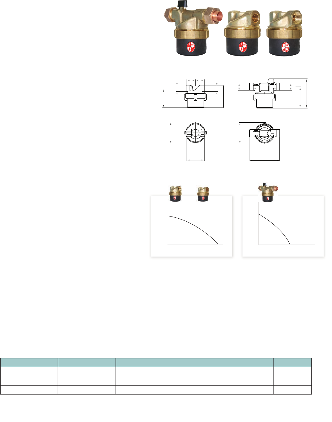
CIRCULATORS autocirc® Series
Potable Hot Water Recirculation Pumps - Undersink
11
Description
autocirc® circulators are energy ef cient using permanent magnet, ECM
(electronically commutated motor) technology. The autocirc circulators
are designed speci cally for standard water heaters. These circulators are
lead-free* and are assembled with a timer, cord and plug.
*CSA certi ed to NSF/ANSI 372 that product contains less than 0.25% lead content by weight on wetted surface.
ecocirc B 23-5 ACT
Materials of Construction
Pump Body: Lead-Free* Brass
O-Ring: EPDM
Bearing: Carbon/Ceramic
Impeller: Nylon/PPO
Motor: High Ef ciency ECM
All Other Wetted Parts: Type 316 Stainless Steel,
Shaft-less and Seal-less construction.
Operating Data Pump
Maximum Working Pressure: 145 PSI (10 Bar)
Maximum Working Temperature: 203ºF (95ºC)
Minimum Working Temperature: 50ºF (10ºC)
Motor
ECM Spherical Motor
115 Volt 60 Hz, 1 Phase
14 Watts Power Consumption
Automatic Overload Protection
Low in-rush current
Model Number Part Number Description Weight
e3-4_-/BDPQC LHB08100098 Lead-Free Brass autocirc 1/2” Fixed Thermostat with Timer 4 lbs.
e3-4_-/BDPRC LHB08100099 Lead-Free Brass autocirc 1/2” Adjustable “ON” Thermostat with Timer 4 lbs.
e3-4_-/BDPQC
e3-4_-/BDPRC
Materials of Construction
Pump Body: Lead-Free* Brass
O-Ring: EPDM
Bearing: Carbon/Ceramic
Impeller: Nylon/PPO
Motor: High Ef ciency ECM
All Other Wetted Parts: Type 316 Stainless Steel,
Shaft-less and Seal-less construction
Operating Data Pump
Maximum Working Pressure: 145 PSI (10 Bar)
Maximum Working Temperature: 203ºF (95ºC)
Minimum Working Temperature: 50ºF (10ºC)
Description
The ecocirc B 23-5 ACT lead-free* pump was designed with highly ef cient electronically
commutated permanent magnet motor (ECM/PM technology) speci cally for potable water
systems. This unique design is perfect for retro ts and systems with tankless water heaters.
No recirculation pipe is required.
CIRCULATORS ecocirc® B 23-5 ACT
Potable Hot Water Recirculation Pumps - Undersink
Motor
ECM Spherical Motor
115 Volt 60 Hz, 1 Phase
60 Watts Power Consumption
Automatic Overload Protection
Low in-rush current
Model Number Part Number Description Weight
ecocirc B 23-5 ACT 6050B7016 Lead-Free Brass autocirc 1/2” Fixed Thermostat with Timer 6.50 lbs.
*CSA certi ed to NSF/ANSI 372 that product contains less than 0.25% lead content by weight on wetted surface.
6.76” (71.7mm)
5.85” (48.7mm)
1.61” (40.8mm)
5.97” (151.74mm)
5.19” (132mm)
2.32” (59mm)3.98” (101mm)
Description
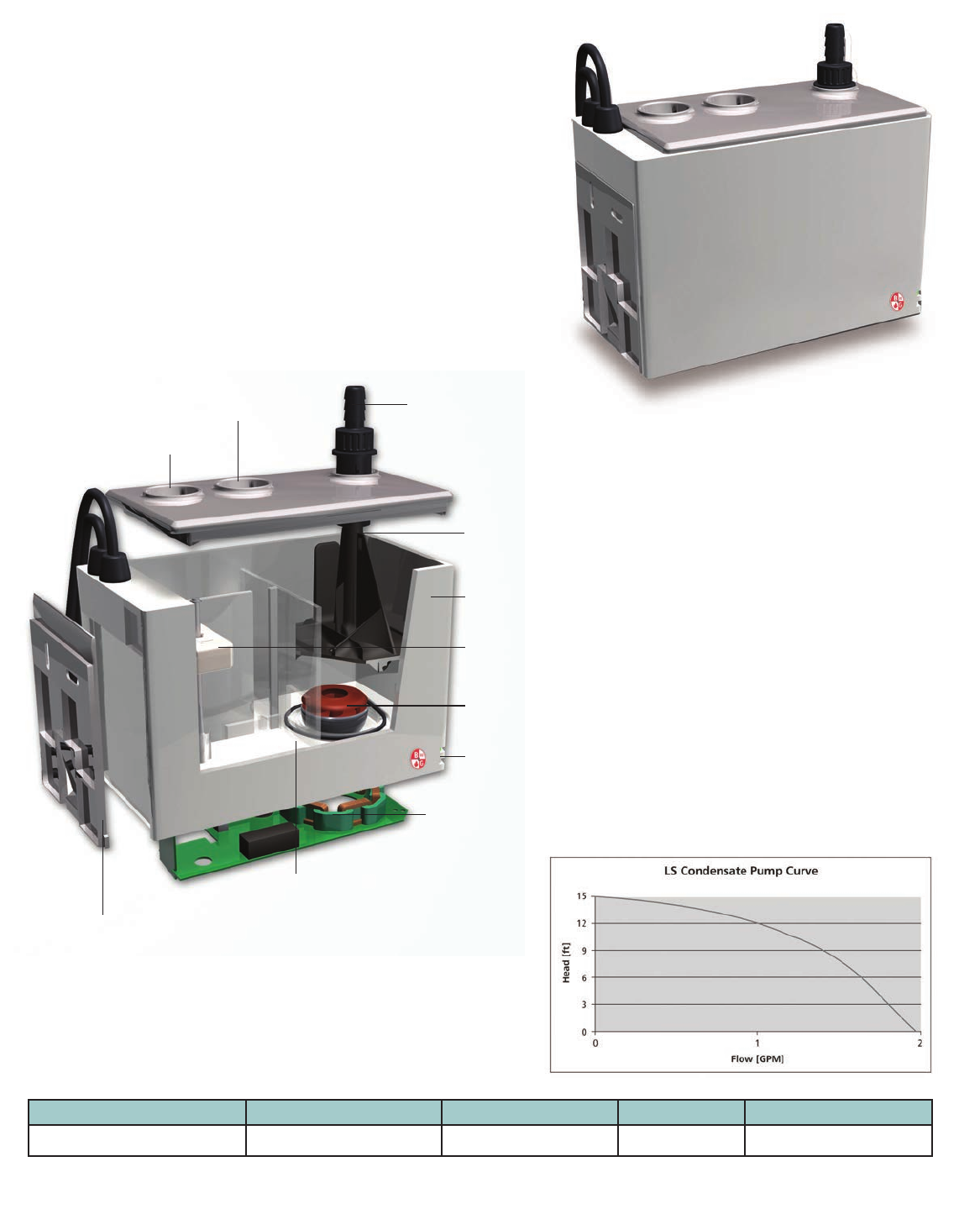
The LS condensate removal pumps are energy efcient lifting stations that
use permanent magnet, ECM (electronically commutated motor) technology.
The LS condensate removal pumps are designed specically for use in
applications where the removal of condensate uid is not possible by gravity.
Materials of Construction
Pump Housing: ABS Material
O-Ring: EPDM or Viton
Bearing: Carbon/Alumina Ceramic
Impeller: Nylon/PPO
Motor: High Efciency ECM
All Other Wetted Parts: Type 316 Stainless Steel,
Shaft-less and Seal-less Construction
Standard Features
Motors are designed with a shaft-less
spherical motor with permanent magnet
technology for improved efciency.
Motor
ECM Spherical Motor
Phase: Single 60 Hz
Voltage: 100-140 volts
Power Consumption: 20 watts
Current draw: 0.1 - 0.2A
Automatic Overload Protection
Low in-rush current
Acid Resistant
All LS condensate removal pumps are made
from acid resistant ABS material
Non-return valve
with bayonet xing
Additional inlet
with cover
Inlet opening
Mounting
bracket with clip
LED signals
Tank
Pressure socket
Permanent magnetic
rotor/impeller unit
Stator of the high efciency
ball bearing pump
Pump sump
Magnetic oat
CIRCULATORS LS Condensate Removal Pump
For Condensing Boilers and Air Conditioning /Cooling Systems
Model Part Number Housing Material Motor Weight
LS Condensate Pump 6098B0000 ABS ECM 3.5 lbs
12
14
12
10
8
6
4
2
001234567
14
12
10
8
6
4
2
001234567
14
12
10
8
6
4
2
001234567
14
12
10
8
6
4
2
001234567
e3-SC4U
GPM
Feet of Head
GPM
Feet of Head
e3-SC6S
e3-SC6N
CIRCULATORS ecocirc® SC Solar Pump
Spherical Motor Pump
Application
• The ecocirc solar pump can be used for most circulation pump
applications without connection to the power grid with direct
connection to a photovoltaic panel.
• This pump is perfect for single family home thermal
solar systems or any circulation pump application where
conventional power is not available, on closed loop systems
Design
• The only moving part is a hemispherical rotor/impeller unit
which sits on an ultra-hard, wear-resistant ceramic ball.
• There are no conventional shaft bearings or seals eliminating
bearing noise and seal leaks.
• This pump is robust and has an estimated service life in excess
of 50,000 hours.
• All parts exposed to the uid are completely corrosion resistant.
Soft Start-up
• When the photovoltaic panel provides suf cient power, the
pump goes through the alignment phase by turning the rotor
into the position required for start-up.
• The processor then waits until the capacitor is suf ciently
charged.
• This enables a start-up with minimal power (less than one watt).
Over-temperature Safety Device
• The ecocirc solar pump comes with an integrated over-
temperature safety device which shuts off the pump electronics
when reaching temperatures over 230°F.
• After reaching a critical temperature 203°F the pump will lower
its speed automatically in order to avoid a total shutdown.
Materials of Construction
Pump Body: Lead-Free* Brass
O-Ring: EPDM
Bearing: Carbon/Alumina Ceramic
Impeller: PPO
Motor: High Ef ciency ECM
All Other Wetted Parts: Type 316 Stainless Steel
Shaft-less, Seal-less Construction
1.18” 1.37”
2.7”
1/2”
1/2”
1 - 18 UNS
3.07”
4.21”
3.14”
3.15”
2.56” 2.56”
e3-SC6N and e3-SC6S e3-SC4U
Technical Data
Motor Design: Electronically commutated spherical motor with permanent magnet rotor/impeller
Voltage: 12 - 24 Volt
Maxium System Temperature: 203ºF (95ºC)
Maxium Pressure: 150 PSI
Power Consumption*: Min. start-up power consumption less than 1 Watt, max. power consumption 22 Watts
Current Draw: 0.25 - 1.46 A
Acceptable Media: Potable hot water recirculation, heating water, water/glycol mixtures, other media on request**
Environment: IP 42
Insulation Class: Class F
* Power consumption and start may vary in different installations. **Please check pump performance with more than 20% glycol.
Available Models
13
*CSA certi ed to NSF/ANSI 372 that product contains less than 0.25% lead content by weight on wetted surface.
** Built-in ball check valve and purge valve.
Model Part Number Description Weight
e3-SC6S 6055B2000 Lead-Free Brass* Solar Circulator 1/2” Sweat 2 lbs.
e3-SC6N 6055B2001 Lead-Free Brass* Solar Circulator 1/2” NPT 2 lbs.
e3-SC4U 6055B2002 Lead-Free Brass* Solar Circulator 1/2” Union Sweat** 2 lbs.
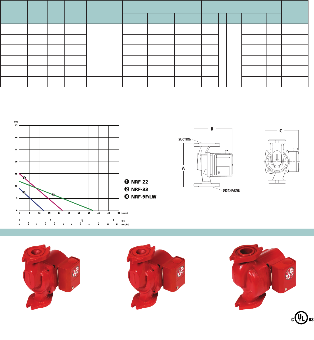
CIRCULATORS Bell & Gossett Cast Iron Wet Rotor Circulators / NRF
14
Description
A residential or light commercial, maintenance free, axial flanged,
in-line, cast iron, wet rotor circulation pump for hydronic heating
systems. UL and cUL Listed.
Operating Data
Maximum Working Pressure: 150 PSI (10 bar)
Maximum Operating Temperature:
NRF-22 & NRF-9F/LW: 240°F (115°C)
NRF-25, NRF-33, NRF-36 & NRF-45: 225°F (107°C)
Materials of Construction
Pump Body: Cast Iron
Impeller: Noryl
Shaft: Ceramic
Bearings: Double-Sintered Carbon
Warranty
Bell & Gossett offers a warranty of 3 years from date of manufacture or
18 months from date of installation (which ever comes first) against
failure as a result of defects in materials and workmanship.
Specifications
Model
Number
Single
Speed
Three
Speed
Part
Number
Flange Sizes
Inches - NPT
Dimensions Inches (mm) Standard 60 Cycle Motor Characteristics* Shipping
Weight
lbs. (Kg)
A B C Watts øVolts F.L. Amps RPM
NRF-9F/LW •103267
3/4, 1, 11/4, 11/2
63/8 (162) 63/16 (157) 51/8 (130) 41
1115
0.40 2800 9.3 (4.2)
NRF-22 •103251 63/8 (162) 63/16 (157) 51/8 (130) 92 0.80 2940 9.3 (4.2)
NRF-25 •103417 63/8 (162) 63/16 (157) 51/8 (130) 125 1.20 2950 10.4 (4.7)
NRF-33 •103350 63/8 (162) 59/16 (141) 47/8 (124) 125 1.10 2950 10.4 (4.7)
NRF-36 •103400 63/8 (162) 67/8 (175) 53/4 (146) 270 2.30 3300 13.1 (6.0)
NRF-45 •103404 1, 11/4, 11/2 81/2 (216) 73/8 (187) 53/4 (146) 270 2.30 3300 14.5 (6.6)
NRF-9F/LW, NRF-22, NRF-25 and NRF-33 are impedance protected.
NRF-36 and NRF-45 are thermally protected.
Dimensions are approximate and subject to change. Contact factory for certified dimensions.
Single Speed NRF Circulator Performance Curves
NRF-33NRF-22NRF-9F/LW
Single Speed NRF Circulators
CIRCULATORS Bell & Gossett Cast Iron Wet Rotor Circulators / NRF
15
Optional Zone Pump Relay Control
The ZoneTrol II AZ-1A is a single zone pump
relay that turns the pump and boiler on when
the thermostat calls for heat. The AZ-1A is ideal
when adding a zone to an existing system
and can be daisy-chained together to control
multiple zones (See page 25.)
NRF-25 NRF-36 NRF-45
Three-Speed NRF Circulators
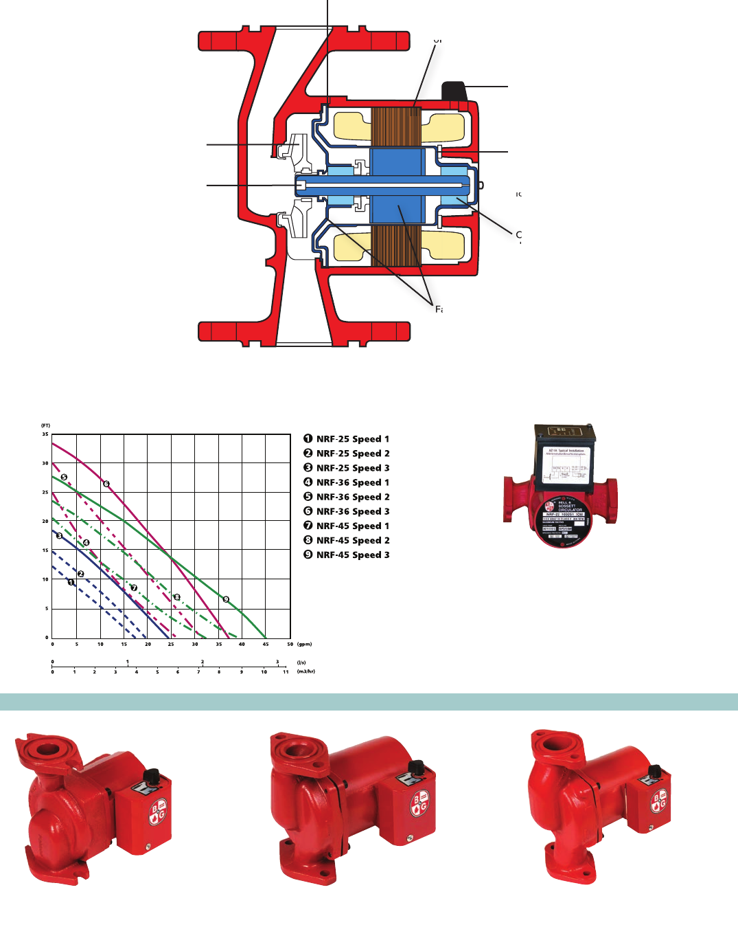
Reliable, maintenance-free, whisper quiet wet
rotor circulators designed for residential and
light commercial heating systems.
DuraGlide™ Bearing System (blue areas in
cutaway illustration) incorporates several
components working together to eliminate
seasonal freeze-up
Powerful motor with high
starting torque provides years
of trouble-free operation
Three speed motors on
select models offer a
wide range of hydraulic
capabilities
One-piece, high-nickel
stainless steel stator can
isolate the stator
from system fluid and
maintains precision
bearing alignment for
longer bearing life
Carbon bearings,
diamond-like ceramic
shaft and generous
clearances are more
resistant to lime, chloride
and oxide build-up
Face plate and rotor sleeve feature
corrosion resistant stainless steel
construction for longer life
Stabilized, heat resis-
tant, non-metallic
impeller. Its closed
design improves
operating efficiency
Self-cleaning particle
shield protects the
shaft and bearings
from system start-up
debris
Three-Speed NRF Circulator Performance Curves
Face plate and rotor sleeve feature
Face plate and rotor sleeve feature
of trouble-free operation
longer bearing life
Carbon bearings,
diamond-like ceramic
CIRCULATORS Lead-Free Wet Rotor Circulators
for Potable Water / NBF & SSF
16
Description
A residential or light commercial, maintenance-free, in-line, lead-free*
bronze or stainless steel, wet rotor circulator for potable water systems
and other applications. Flanged, union or sweat models available.
UL and cUL listed.
Operating Data
Maximum Working Pressure: 150 PSI (10 bar)
Maximum Operating Temperature:
NBF-25, NBF-33, NBF-36, NBF-45: 225°F (107°C)
All Others: 230°F (110°C)
Materials of Construction
Pump Body NBF: 100% Lead-Free* Bronze
SSF: Stainless Steel
Impeller : Noryl
Shaft: Ceramic
Bearings: Double-Sintered Carbon
Warranty
Bell & Gossett offers a warranty of three years from date of manufacture
or 18 months from date of installation (which ever comes first) against
failure as a result of defects in materials and workmanship.
*CSA certied to NSF/ANSI 372 that product contains less than 0.25% lead content by
weight on wetted surface.
SSF-9 NBF-9
Cross Reference
BELL & GOSSETT GRUNDFOS* TACO**
NBF-8S/LW UM 15-10B5 003B
NBF-9U/LW UP 15-18SU 006B
NBF-10S/LW UP 15-18B5 006B
NBF-12U/LW UP 15-42SU 005B
NBF-12F/LW UP 15-42SF 005B
NBF-18S UP 15-42B5 —
NBF-22U UP 25-64SU 007B
NBF-22 UP 25-64SF 007B
SSF-22 UP25-64SF 007B
NBF-25 UPS15-58 00R-MS
NBF-33 — 0010B
NBF-36 UP26-96BF 0011B
UP26-99BF 0013B
UP26-64SF 0014B
NBF-45 UP43-75BF —
Model
Number
Part
Number Connections
Dimensions
Inches (mm)
ABCWatts Volts
115
F.L. Amps RPM
Shipping
Weight
lbs. (Kg)
Standard 60 Cycle
Motor Characteristics*
1
O
103257LF
103258LF
103259LF
103260LF
103261LF
103316LF
103252LF
103255LF
103418LF
103351LF
103401LF
103405LF
103360LF
103358LF
103361LF
103357LF
103362LF
0.39
0.40
0.46
0.48
0.48
0.74
0.80
0.80
1.10
1.10
2.30
9.0 (4.1)
9.3 (4.2)
9.0 (4.1)
9.5 (4.3)
9.3 (4.2)
9.0 (4.1)
9.5 (4.3)
9.3 (4.2)
10.4 (4.7)
10.4 (4.7)
13.1 (6.0)
14.5 (6.6)
9.3 (4.2)
9.5 (4.3)
9.3 (4.2)
9.5 (4.3)
9.3 (4.2)
39
41
55
55
55
90
92
92
125
125
270
270
41
55
55
92
92
3000
2800
2940
2950
3300
1/2" Sweat
Union**
1/2" Sweat
Flange 3/4, 1, 11/4, 11/2
Union**
1/2" Sweat
Flange 3/4, 1, 11/4, 11/2
Union**
Flange 3/4, 1, 11/4, 11/2
Flange 3/4, 1, 11/4, 11/2
Flange 3/4, 1, 11/4, 11/2
Flange 1, 11/4, 11/2
Union**
Flange 3/4, 1, 11/4, 11/2
Union**
Flange 3/4, 1, 11/4, 11/2
Union**
5 (127)
6 1/8 (156)
5 (127)
6 3/8 (162)
6 1/8 (156)
5 (127)
6 3/8 (162)
6 1/8 (156)
6 3/8 (162)
6 3/8 (162)
6 3/8 (162)
8 1/2 (216)
6 1/8 (156)
6 3/8 (162)
6 1/8 (156)
6 3/8 (162)
6 1/8 (156)
5 7/32 (132)
5 1/16 (129)
5 7/32 (132)
5 9/16 (141)
5 1/16 (129)
5 7/32 (132)
5 9/16 (141)
5 1/16 (129)
6 3/16 (157)
6 3/16 (157)
6 7/8 (175)
7 3/8 (187)
5 1/16 (129)
5 9/16 (141)
5 1/16 (129)
5 9/16 (141)
5 1/16 (129)
4 7/8 (124)
4 7/8 (124)
4 7/8 (124)
4 7/8 (124)
4 7/8 (124)
4 7/8 (124)
4 7/8 (124)
4 7/8 (124)
5 1/8 (130)
5 1/8 (130)
5 3/4 (146)
5 3/4 (147)
4 7/8 (124)
4 7/8 (124)
4 7/8 (124)
4 7/8 (124)
4 7/8 (124)
* Impedance protected
** Union Connections are available in 3/4" NPT, 1/2" sweat & 3/4" sweat.
NBF-8S/LW
NBF-9U/LW
NBF-10S/LW
NBF-12F/LW
NBF-12U/LW
NBF-18S
NBF-22
NBF-22U
NBF-25
NBF-33
NBF-36
NBF-45
SSF-9U/LW
SSF-12F/LW
SSF-12U/LW
SSF-22
SSF-22U
0.40
0.48
0.80
2800
2940
*Grundfos is a registered trademark of Grundfos Pumps Corp.
**Taco is a registered trademark of Taco, Inc.
C
DISCHARGE
SUCTION
A
B
Specifications
Single Speed–NBF/SSF 60 HZ Performance Curve Three Speed–NBF 60 HZ Performance Curve
17
CIRCULATORS Lead-Free Wet Rotor Circulators
for Potable Water / NBF & SSF – continued
CIRCULATORS Series LR™ Maintenance-Free Circulators
Operating Data
Maximum Working Pressure: 150 PSI (10 bar)
Maximum Operating Temperature: 225°F (107°C)
Specifications
LR-20
LR-15B
A
BC
Model
Number
Part
Number
Pump
Body
Material
Flange
Sizes
Inches-NPT
Dimension Inches (mm) Standard 60Hz
Motor Characteristics* Approx.
Shpg. Wt.
lbs (Kg)
A B C Watts ØF.L. Amps FL Amps RPM
LR-20WR 106507 Cast Iron 3/4, 1, 1-1/4, 1-1/2 6-3/8 (162) 6 (152) 3-7/8 (98) 125 1 115 1.10 2950 10.4 (4.7)
LR-15BWR 106514LF Bronze 3/4, 1, 1-1/4, 1-1/2
Materials of Construction
Pump Body: LR-20WR: Cast Iron
LR-15BWR: Lead-Free* Bronze
Impeller: Noryl®
Shaft: Ceramic
Bearings: Carbon
*CSA certied to NSF/ANSI 372 that product contains less than
0.25% lead content by weight on wetted surface.
CIRCULATORS Maintenance-Free Circulators
a superior alternative to large wet rotor pumps
�
PL-50
PL-55
PL-75
PL-130
PL-45
PL-36
PL-30
1
B&G’s powerful, dry-motor design delivers
exceptional performance. . . . 25% more
efficient than competition.
2
Precision-machined and balanced alloy steel
rotor for superior performance.
3
Quick-connect wire nut leads and dual
knock-outs make for fast, sure hook-ups.
4
Solid “Stiff-Shaft” design is constructed of
high-strength alloy steel impervious to
cracking caused by thermal stresses.
5
XL-11™ Precision-Crafted Bearing System...
is permanently oil lubricated... completely
maintenance free...precisely positioned for
long-life and isolated for quiet operation.
6
Advanced close-coupled design increases
pump life and efficiency, assures
dependable seasonal start-ups and can
easily handle difficult water conditions.
7
Tough, durable seal system features a
carbon/silicon carbide seal on a stainless
steel shaft sleeve for long life and
rugged operation.
8
Double sided I-Seal™ design for optimum
efficiency.
123
4
5
6
7
8
Specifications
* 230/60/1 motors available upon request. Models PL-75 and PL-130 have four bolt hole flange connection, all others have two bolt hole flange connectors.
Dimensions are approximate and subject to changes. Contact factory for certified dimensions.
Operating Data
Maximum Working Pressure: 150 PSI (10.3 bar)
Maximum Operating Temperature: 225°F (107°C)
18
PL-30, 36, 45, 50, 55 PL-75, 130
Materials of Construction
Booster Body: Cast Iron or Lead-Free* Bronze
Face Plate: Stainless Steel
Impeller: 30% Glass Filled Noryl® (PL-55 & PL-130): Glass Filled PPS
Shaft: Carbon Steel (PL-55 & PL-130): Stainless Steel
Shaft Sleeve: Stainless Steel (PL-55 & PL-130): None
Seal: Mechanical, Carbon on Silicon Carbide
Motor Bearings: Sealed Precision Steel Ball Bearing Permanently Lubricated
Motor Type: ODP
Elastomers: EPDM
*CSA certied to NSF/ANSI 372 that product contains less than 0.25% lead content by weight
on wetted surface.
Flange Motor Characteristics* Dimensions in inches (mm) Approx.
Cast Iron Lead Free Size @ 60 Hz (Open Drip-Proof) Shipg. Wt.
Model No. Part No. Model No. Part No. Inches - NPT HP ø Voltage RPM A B C D E Ibs. (Kg)
3/4, 1,
PL-30 1BL012 PL-30B 1BL013LF 1 1/4, 1 1/2 1/12 2650 8 5/8 (219) 6 3/8 (162) 7 1/8 (181) 43/16 (106) 4 3/8 (111) 11.6 (5.3)
PL-36 1BL001 PL-36B 1BL003LF 1 1/4, 1 1/2 1/6 3300 8 5/8 (219) 6 3/8 (162) 7 1/8 (181) 4 3/16 (106) 4 3/8 (111) 13.1 (6.0)
1, 1 1/4
PL-45 1BL002 PL-45B 1BL004LF 1 1/2 1/6 3300 9 1/8 (232) 8 1/2 (216) 7 1/4 (184) 4 5/8 (117) 4 1/2 (114) 14.5 (6.6)
1, 1 1/4
PL-50 1BL016 PL-50B 1BL017LF 1 1/2 1/6
1 115 3300 9 1/8 (232) 8 1/2 (216) 7 1/4 (184) 4 5/8 (117) 4 1/2 (114) 14.5 (6.6)
PL-55 1BL032 PL-55B 1BL068LF 1 1/4, 1 1/2 2/5 3250 9 9/16 (243) 6 3/8 (162) 7 15/16 (202) 4 3/16 (106) 4 3/4 (121) 13.1 (6.0)
PL-75 1BL034 PL-75B 1BL035LF 2 1/6 3400 9 15/16 (252) 8 1/2 (216) 7 3/8 (187) 5 3/16 (132) 4 5/8 (117) 18.5 (8.4)
PL-130/ 2” 1BL063 PL-130B/ 2” 1BL065LF 2 2/5 3200 10 3/4 (273) 8 1/2 (216) 8 1/4 (210) 5 3/16 (132) 5 1/8 (130)
PL-130/ 3” 1BL070 PL-130B/ 3” 1BL072LF 2 1/2 & 3 2/5 3200 10 3/4 (273) 8 1/2 (216) 8 1/4 (210) 6 (152) 5 1/8 (130) 27 (12.2)
3/4, 1,
3/4, 1,
22 (10)
19
Specifications
NBF-8S/TP
NBF-10S/TP
NBF-9U/TP
SSF-9U/TP
With Timer & Cord
Series 100
Series PR
Series HV
2"
2-1/2"
LD3
HD3
PD-35S
PD-35T
PD-37S
PD-37T
PD-38S
PD-38T
PD-40S
PD-40T
Model
Number
100NFI
100BI
PR
PR BI
HV NFI
HV BI
2 NFI
2 BI
2-1/2
2-1/2 BI
LD3
LD3 BI
HD3
HD3 BI
PD35S
PD35S BI
PD35T
PD35T BI
PD37S
PD37S BI
PD37T
PD37T BI
PD38S
PD38S BI
PD38T
PD38T BI
PD40S
PD40S BI
PD40T
PD40T BI
Model Number Part Number
Cast Iron
106189
106190
102206
102207
102210
102230
102214
102232
102218
102219
102222
102223
102226
102227
105089
105090
105093
105094
105097
105098
105101
105102
105121
105122
105133
105134
105151
105152
105137
105138
Model Number Part Number
Bronze
100 AB
100 BNFI
PR AB
HV AB
HV BNFI
2AB
2 BNFI
2-1/2 AB
LD3 AB
HD3 AB
PDB35S
PDB35T
PDB37S
PDB37T
PDB38S
PDB38T
PDB40S
PDB40T
106192LF
106197LF
102208LF
102231LF
102213LF
102233LF
102217LF
102220LF
102224LF
102228LF
105092LF
105096LF
105100LF
105104LF
105123LF
105135LF
105153LF
105139LF
3/4, 1
1-1/4, 1-1/2
3/4, 1
1-1/4, 1-1/2
1, 1-1/4,
1-1/2
2
2-1/2
3
3
3
3
3
3
3
3
3
3
Flange
Size
Inches
(NPT) HP
Motor Characteristics*
@ 60 Hz
1/12
1/6
1/6
1/6
1/4
1/4
1/3
1/2
1/2
3/4
3/4
1
1
1-1/2
1-1/2
1
1
3
1
3
1
3
1
3
115 - with
built-in
overload
protection
115/230
115/230
208-230/460
115/230
208-230/460
115/230
208-230/460
115/230
208-230/460
14-7/8 (378)
15-1/4 (387)
15-3/8 (391)
16-5/8 (422)
17-1/4 (438)
17-1/4 (438)
17-1/2 (445)
20-1/4 (514)
20-1/4 (514)
20-1/4 (514)
20-1/4 (514)
22-3/4 (578)
24 (610)
24-3/4 (629)
21-7/8 (556)
AVoltage
6-3/8 (162)
8-1/2 (216)
8-1/2 (216)
8-1/2 (216)
10 (254)
10 (254)
10 (254)
12 (305)
12 (305)
12 (305)
12 (305)
14-1/2 (368)
14-1/2 (368)
14-1/2 (368)
14-1/2 (368)
B
Dimensions in Inches (mm)
(Open Drip-Proof)
12-3/4 (324)
12-3/4 (324)
13 (330)
14 (356)
14 (356)
14 (356)
14-1/4 (362)
16-7/8 (429)
16-7/8 (429)
16-7/8 (429)
16-7/8 (429)
19 (483)
20-1/4 (514)
21 (533)
18-1/8 (460)
C Cast Iron
20 (9)
30 (14)
28 (13)
36 (16)
54 (24)
53 (24)
55 (25)
75 (34)
75 (34)
75 (34)
75 (34)
128 (58)
125 (57)
130 (59)
127 (58)
Bronze
21 (10)
32 (15)
30 (14)
39 (18)
58 (26)
57 (26)
59 (27)
80 (36)
80 (36)
80 (36)
80 (36)
138 (63)
135 (61)
140 (64)
137 (62)
Approximate Shpg.
Wt. lbs. (Kg)
PD-38 and PD-40 are ball bearing, maintenance-free design.
*
Special motors available upon request. Dimensions are approximate and subject to changes.
Contact factory for certified dimension.
1
B&G Motor — The heart of the booster.
The finest circulator motor available.
Sleeve bearing, oil lubricated with
replaceable resilient motor mounts.
B&G motors are designed and
manufactured specifically for the
B&G boosters.
2
Noise dampening coupler. B&G’s own
flexible spring design adds to quiet
operation. Do not accept a substitute.
3
Long bronze sleeve bearings maintain
exact shaft alignment. Provides for constant
circulation of oil over bearing surfaces.
4
Precision ground pump shaft is
oversized to provide large bearing
surfaces. Hardened integral thrust
collar minimizes end-thrust to
ensure long seal and bearing life.
5
The B&G mechanical seal is
designed to withstand the wide
range of water temperatures,
pressures, additives and dissolved
solids common in hydronic
systems.
6
Centrifugal impeller prevents
accumulation of air at seal faces to assure
long life. Close impeller/body tolerances
minimize water slippage and maximize
efficiency.
PD40
PD38
PD37
PD35
HD3
HV
2”
2-1/2” & LD3
PR
SER100
123
4
5
6
Operating Data
Maximum Working Pressure: 125 PSI (8.6 bar)
Maximum Operating Temperature:
Standard Seal: 225°F (107°C) continuous
Special Seals: 250°F (121°C) continuous
CIRCULATORS Oil Lubricated Circulators Three-Piece
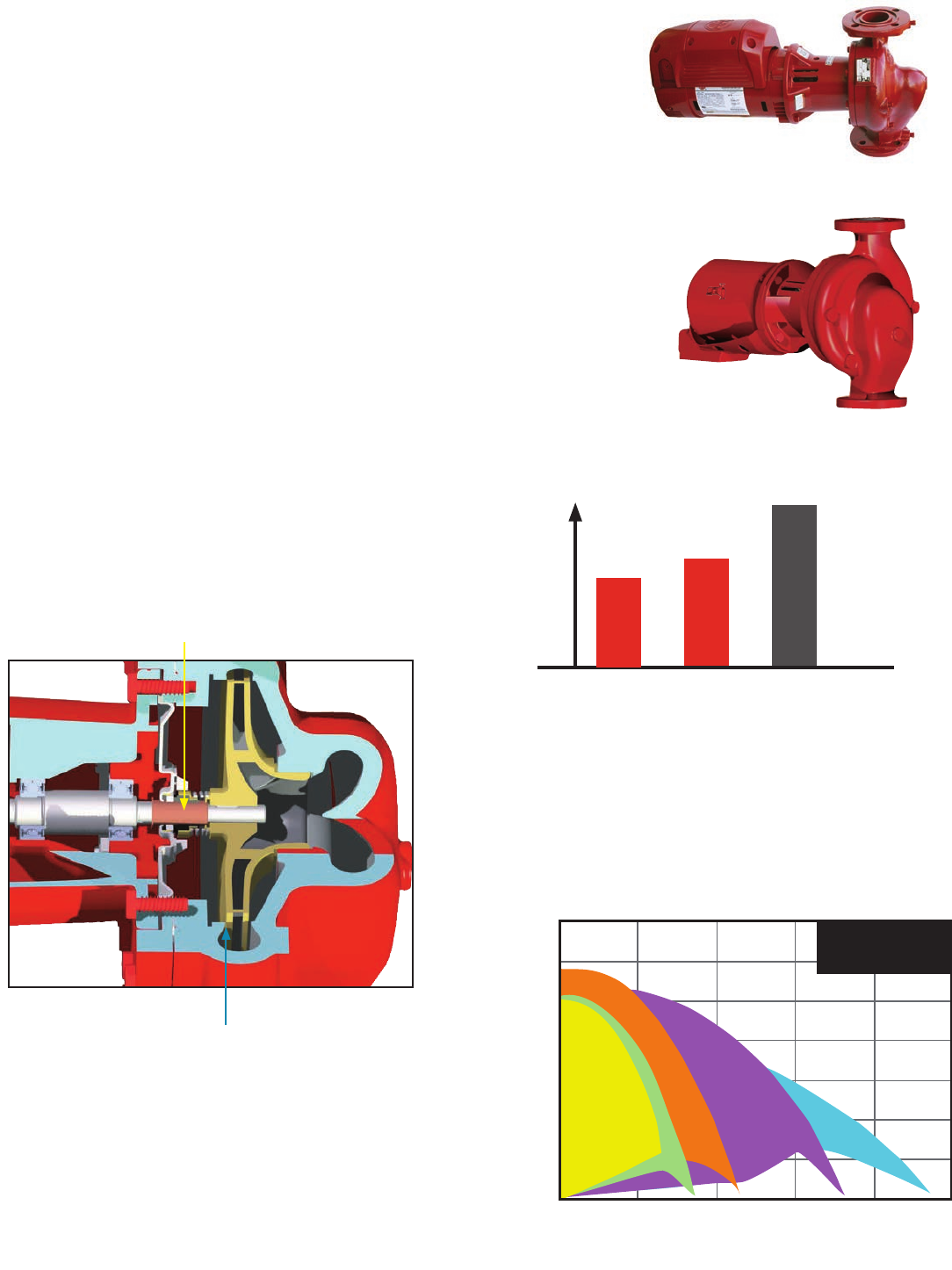
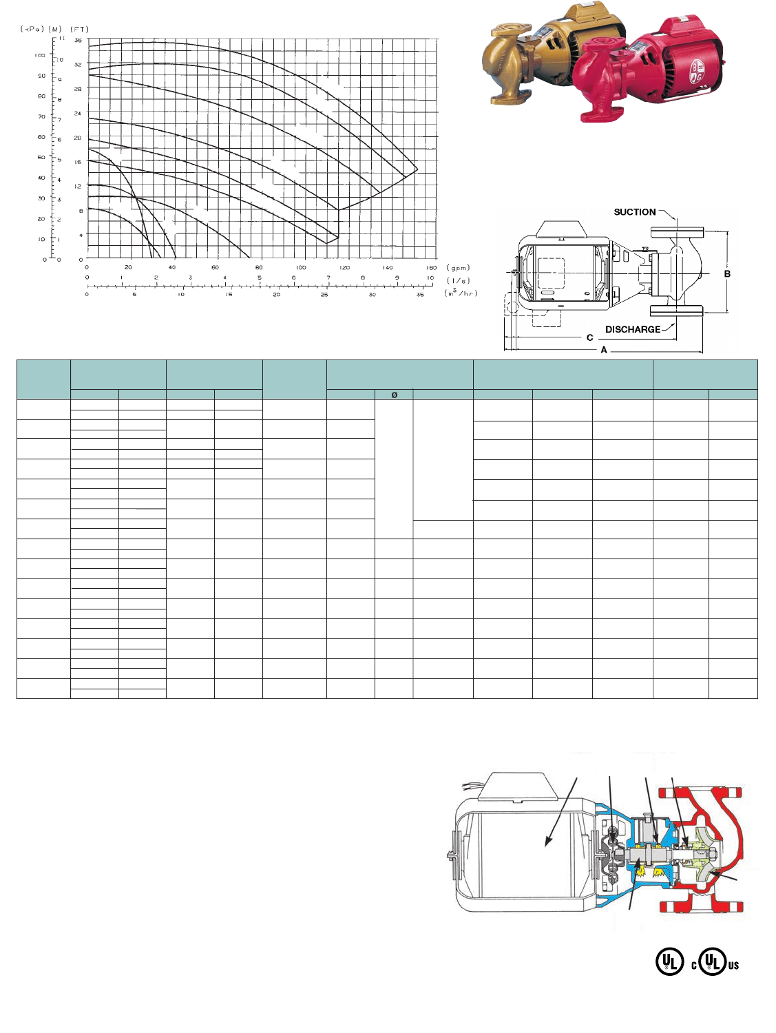
CIRCULATORS Series 60 In-Line Mounted Centrifugal Pump
Now Available with ECM Motor
20
Quiet operation
The XL-11® Precision-Crafted Bearing System, advanced fluid
passage design and B&G permanently lubricated motor come
together to deliver smooth, quiet, maintenance-free performance.
Internally self-flushing seal
Bell & Gossett’s open-seal chamber design provides superior
flow circulation around the seal faces, resulting in reduced heat
buildup, increased particle removal and superior seal-face flushing.
It all adds up to long, trouble-free seal performance.
Impeller
State-of-the-art hydraulically balanced impellers and resilient-
mounted motors provide smooth, quiet operation.
Materials of Construction
Body: Cast Iron (Bronze Fitted)
Cast Bronze (All Bronze)
Impeller: Cast Bronze
Motor Shaft: Alloy Steel
Pump Shaft: Steel
Volute Gasket: Cellulose Fiber
Shaft Sleeve: Copper Alloy
Bracket: Cast Iron with Stainless Steel
Face Plate: 304 Stainless Steel
Mechanical Seal: Buna/Carbon-Ceramic
Standard: -20°F to 225°F
Operating Data
Maximum working pressure: 175 PSI
Operating temperature: 225°F
Description
A maintenance-free, in-line, cast iron centrifugal
pump for header pump applications.
Designed for a variety
of applications
• Hydronic heating & cooling systems
• Domestic water
• Fluid transfer
Product Features
• Maintenance-free pump and motor design
• Internally self-ushing mechanical seal
• XL11® lubrication system
• Factory tested, Qualtiy Product
• ISO 9001 certied
• Neoprene coupling
• Compact design
• Easy installation
• Wide range of standard sizes
• Backed by B&G three-year warranty
Noise Level
Series 60
Pump
Competitor’s
Pump
Series 60 with
ECM Motor
Pump
Series 60 with ECM Motor Pump is 5% quieter
than standard Series 60
Shown with optional ECM motor
35
30
25
20
15
10
5
00 50 100 150 200 250
Hydraulic Curve Performance Range e-60 @ 1725 RPM
Head (Feet)
Flow (GPM)
656S
655S
654S
650S
651S
652S
653S
Hydraulic Curve Performance Range
Series 60 with ECM
ECM Performance Curves
Series 60 ECM
Variable Speeds
CIRCULATORS Series 60 In-Line Mounted Centrifugal Pump
21
Model
Suction And
Discharge
Size
Inches NPT
Pump Dimension in Inches (mm)
F G K L M N P R S T
601,602 & 603 1 6-7/16 (164) 3-7/16 (87) 3-5/8 (92) 1-3/8 (35) 2-1/2 (64) 7-1/2 (190) 3/4 (19) 5 (127) 6 (152) 11 (279)
604,605 & 606 1-1/4 6-7/16 (164) 3-7/16 (87) 3-5/8 (92) 1-3/8 (35) 2-1/2 (64) 7-1/2 (190) 3/4 (19) 5 (127) 6 (152) 11 (279)
607,608 & 609 1-1/2 6-9/16 (167) 3-5/8 (92) 3-3/4 (95) 1-3/8 (35) 2-3/4 (70) 7-7/8 (200) 3/4 (19) 5 (127) 6-1/2 (165) 11-1/2 (292)
613,614 & 621 1-1/2 6-11/16 (170) 3-3/8 (86) 4-1/16 (103) 1 (25) 3-9/16 (90) 8-9/16 (217) 3/4 (19) 6-1/2 (165) 7 (176) 13-1/2 (343)
617,618,622 &
623 1-1/2 9-3/8 (238) 3-1/4 (83) 4-5/8 (117) 1 (25) 3-7/8 (98) 9-1/2 (241) 3/4 (19) 6-1/2 (165) 7 (176) 13-1/2 (343)
610,611 & 612 2 6-11/16 (164) 3-3/4 (95) 3-3/4 (95) 1-3/8 (35) 2-7/8 (73) 8 (203) 13/16 (21) 5 (127) 6-1/2 (165) 11-1/2 (292)
615,616 2 6-15/16 (170) 3-1/2 (89) 4-3/8 (111) 1 (25) 4 (102) 9-3/8 (238) 13/16 (21) 6-1/2 (165) 7 (176) 13-1/2 (343)
619,620 &624 2 9-3/8 (238) 3-1/2 (89) 4-3/4 (121) 1 (25) 4-1/8 (105) 9-7/8 (251) 13/16 (21) 6-1/2 (165) 7-1/2 (165) 14 (356)
Maximium working pressure 175 PSI (12 Bar)
Specications
Series 60
Standard Sizes
1750 RPM
Series 60
Standard Sizes
1750 RPM
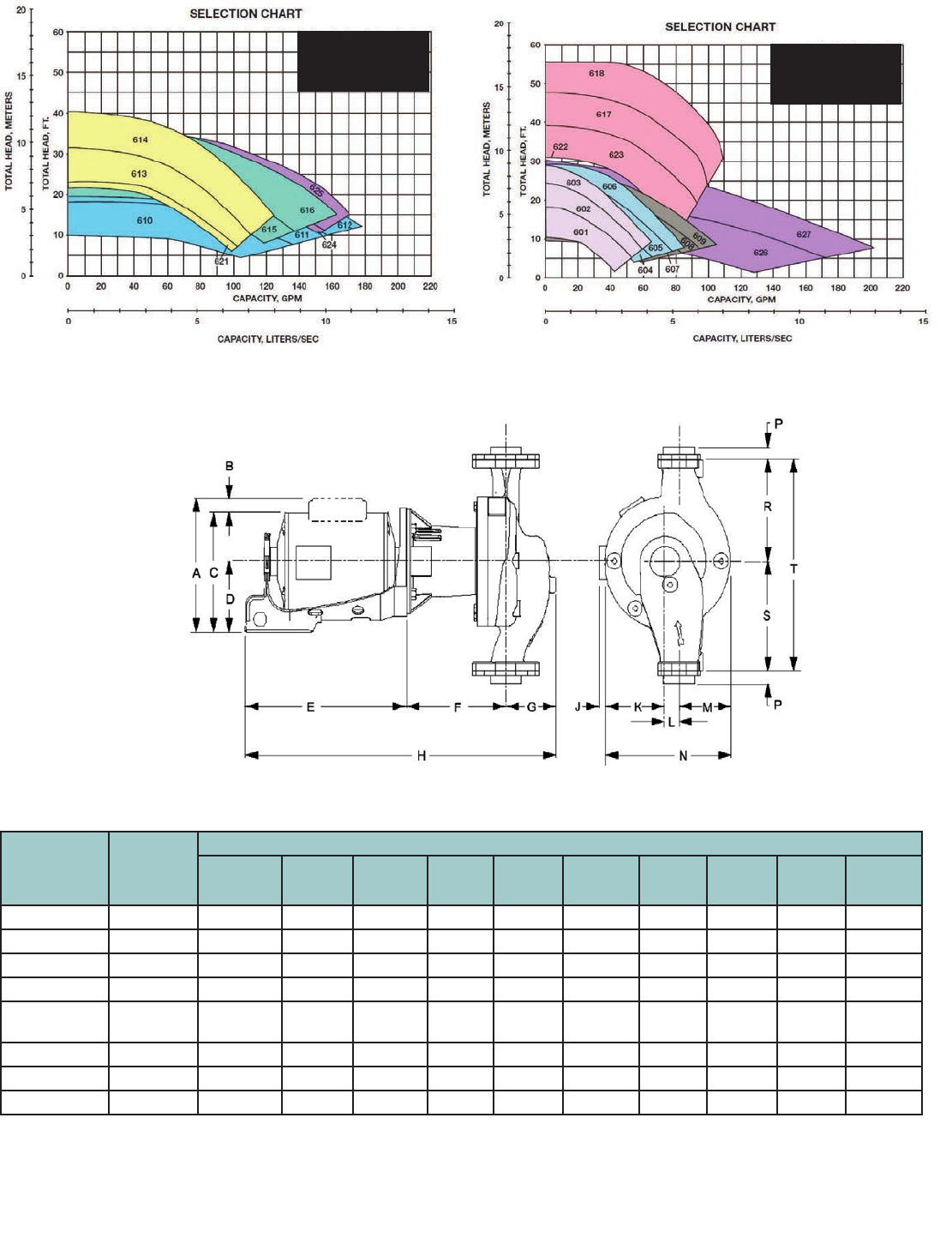
FLANGES Check-Trol™ Isolation Flow Control Flange
22
Description
The Check-Trol flange is a combination isolation valve, flow control
valve, and companion flange for circulators. The ball valve allows
the circulator to be removed from the system without draining the
system. The internal spring check prevents gravity circulation. Free
floating companion flange makes pump installation a snap.
Specifications
Operating Data
Maximum Working Pressure: 150 PSI (10 bar)
Maximum Operating Temperature: 200°F (93°C)
* Not for use with NRF/NBF-45, HV anges required.
Dimensions and weights are approximate and subject to change. Contact factory for certied dimensions. Check-Trol ange is sold with an isolation ange as a pair.
** B1 Dimension is overall length of isolation ange. The part numbers and shipping weights are for one Check-Trol ange and one isolation ange, capscrews and nuts.
Companion
Flange
Flow Control
Valve
Isolation
Valve
Materials of Construction
Valve Body: Lead-Free* Brass
Flange: Chrome Plated Steel
Ball: Chrome Plated Lead-Free* Brass
Packing: PTFE
Seat Ring: PTFE
Stem: Lead-Free* Brass
Spring Check: Nitrile, Acetal, Stainless Steel
*CSA certied to NSF/ANSI 372 that product contains less than
0.25% lead content by weight on wetted surface.
Model
Number
Size
Inches
Use with
Following
Circulators
Dimensions - Inches (mm)
Following Circulators Approx.
Shpg. Wt.
Ibs. (Kg)
A B
B1**
C D
101231LF
3/4” NPT x Flange ecocirc auto and vario
ecocirc XL 20-35,
36-45, 55-45
NRF/NBF/SSF
Wet Rotors*
Series PL-30, PL-36,
PL-55
Series 100, PR and LR
3/4” NPT
3-7/64” (79) 2-27/64” (61.5)
2” (50.5)
4-23/32” (120)
3.4 (1.5)
)
101232LF
1” NPT x Flange
1” NPT
3-15/16” (100) 2-57/64” (73.3)
2-5/32” (54.7)
4-23/32” (120)
4.4 (2.0)
101233LF
1-1/4” NPTx Flange
1-1/4” NPT
4-25/32” (121.4) 3-19/64” (84)
3” (76.2) 6-7/32” (158)
6.3 (2.8)
101245LF
1-1/2” NPT x Flange
1-1/2” NPT
4-27/32” (122.9) 3-23/64” (85.5)
3” (76.2) 6-7/32” (158)
6.6 (3.0)
101236LF
3/4” SWT x Flange
3/4” SWT
3-21/64” (84.5) 2-41/64” (67)
2” (50.5) 4-23/32” (120)
3.4 (1.5)
101237LF
1” SWT x Flange
1” SWT
4-1/64” (102) 3” (75.3)
2-5/32” (54.7) 4-23/32” (120)
4.2 (1.9)
101238LF
1-1/4” SWT x Flange
1-1/4” SWT
4-55/64” (123.4) 3-25/64” (86)
3” (76.2) 6-7/32” (158)
5.9 (2.7)
101247LF
1-1/2” SWT x Flange
1-1/2” SWT
5-1/64” (127.4) 3-35/64” (90)
3” (76.2) 6-7/32” (158)
6.5 (3.0)
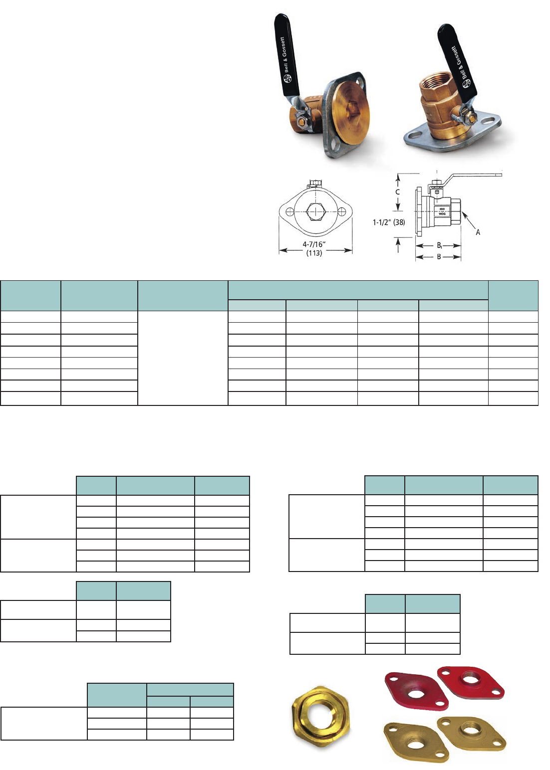
Description
The isolation flange is a combination of an isolation ball valve and
a companion flange for circulators. The isolation flange allows easy
service or replacement of the circulator without the need to drain
the system. The isolation flange fits the Bell & Gossett NRF/NBF/SSF
wet rotors, Series PL, Series 100, HV, PR and LR circulators.
ISOLATION FLANGES
Operating Data
Maximum Working Pressure: 150 PSI (10 bar)
Maximum Operating Temperature: 250°F (121°C)
Materials of Construction
Valve Body: Lead-Free* Brass
Flange: Chrome Plated Steel
Ball: Chrome Plated Lead-Free* Brass
Packing: PTFE
Seat Ring: PTFE
Stem: Lead-Free*Brass
*CSA certied to NSF/ANSI 372 that product contains less than
0.25% lead content by weight on wetted surface.
Specifications
23
Union Connection for NBF Circulators
Flanges for Cast Iron Circulators
Companion Flanges
Flanges for Bronze Circulators
Model
Number
Size
Inches
Use with
Following
Circulators
Dimensions - Inches (mm)
Following Circulators Approx.
Shpg. Wt.
Ibs. (Kg)
A B C D
101221LF 3/4” NPTF IF
ecocirc auto and vario
ecocirc XL 20-35,
36-45, 55-45
NRF/NBF/SSF
wet rotors
Series PL-30,
PL-36, PL-55
Series 100, PR and LR
Does not include
NRF/NBF-45
3/4” NPT 2-27/64” (61.5) 2” (50.5) 4-47/64” (120) 3.2 (1.5)
101222LF 1” NPTF IF 1” NPT 2-57/64” (73.3) 2-5/32” (54.7) 4-47/64” (120) 4.1 (1.9)
101223LF 1-1/4” NPTF IF 1-1/4” NPT 3-19/64” (84) 3” (76.2) 6-7/32” (158) 5.8 (26)
101241LF 1-1/2” NPTF IF 1-1/2” NPT 3-23/64” (85.5) 3” (76.2) 6-7/32” (158) 6.1 (28)
101226LF 3/4” SWT IF 3/4” SWT 2-41/64” (67) 2” (50.5) 4-23/32” (120) 3.2 (1.5)
101227LF 1” SWT IF 1” SWT 3” (75.3) 2-5/32” (54.7) 4-23/32” (120) 3.9 (1.8)
101228LF 1-1/4” SWT IF 1-1/4” SWT 3-25/64” (86) 3” (76.2) 6-7/32” (158) 5.4 (25)
101243LF 1-1/2” SWT IF 1-1/2” SWT 3-35/64” (90) 3” (76.2) 6-7/32” (158) 6 (27)
“IF” = “Isolation Flange”
Note: Dimensions and weights are approximate and subject to change. Contact factory for certified dimensions.
The part numbers and shipping weights are for two isolation flanges, capscrews and nuts.
Size
(NPT)
Master Carton of 12
Part No.
Set of 2
Part No.
Series 100, PR
NRF-22, NRF-9F/LW,
NRF-33, NRF-36
PL-30, PL-36, PL-55
ecocirc XL
3/4”
101001 101201
1”
101002 101202
1-1/4”
101003 101203
1-1/2”
101004 101204
Series HV, PL-45
PL-50, NRF-45
ecocirc XL
1”
101005 101205
1-1/4”
101006 101206
1-1/2”
101007 101207
Size
(NPT)
Set of 2
Part No.*
PL-75, PL-130/2
”
ecocirc XL 15-75 2”
101215
PL-130/3
”
ecocirc XL 40-275
2-1/2”
101219
3”
101217
Union
Connection
Set of Two
Model No. Part No.
NBF-22U, NBF-12U/LW
NBF-9U/LW
1/2” sweat
UC-1/2S 113203LF
3/4” sweat
UC-3/4S 113201LF
3/4” NPT
UC-3/4NPT 113202LF
Size
(NPT)
Master Carton of 12
Part No.
Set of 2
Part No.
Series 100B, PRAB,
NBF-22, NBF-12F/LW,
NBF-33, NBF-36
PL-30B, PL-36B
ecocirc XLB
3/4”
101011LF 101208LF
1”
101012LF 101209LF
1-1/4”
101013LF 101210LF
1-1/2”
101014LF 101211LF
Series HV, PL-45B
PL-50B, NBF-45
ecocirc XLB
1”
101015LF 101212LF
1-1/4”
101016LF 101213LF
1-1/2”
101017LF 101214LF
Size
(NPT)
Set of 2
Part No.*
PL-75B, PL-130B/2
”
ecocirc XLB 15-75 2”
101216LF
PL-130B/3
”
ecocirc XLB 40-275
2-1/2”
101220LF
3”
101218LF
*Includes Fasteners
*Includes Fasteners
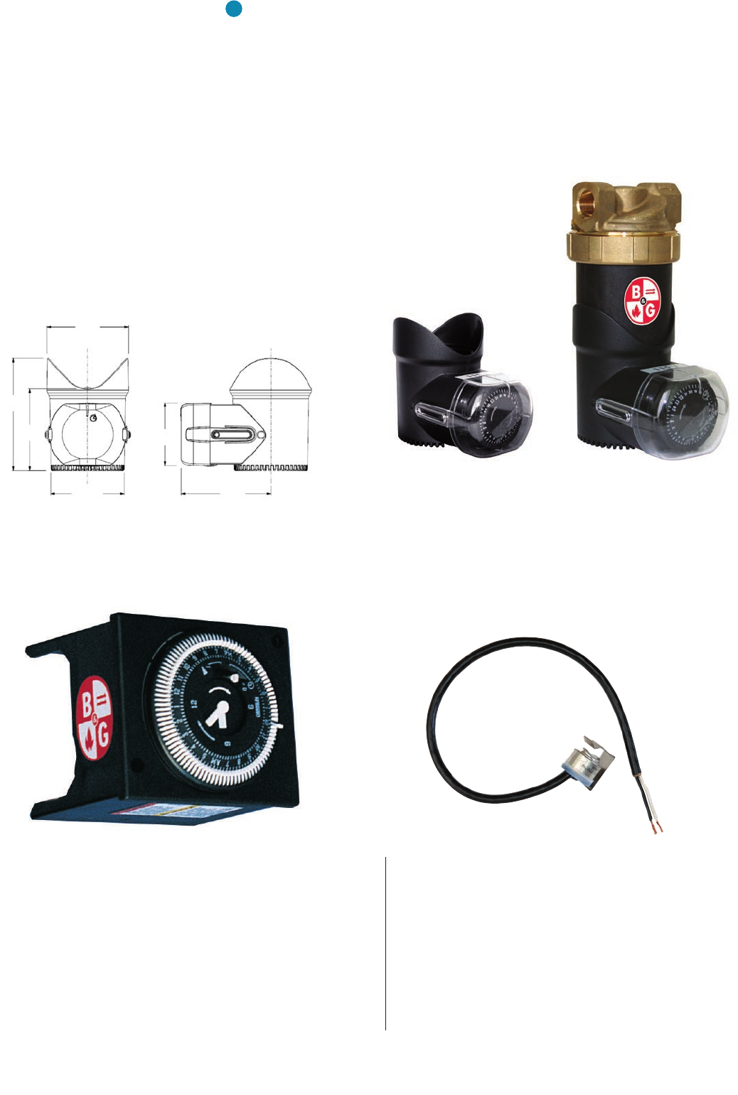
CONTROLS ecocirc® SERIES TIMER
24
TC-1 Automatic Timer Kit (Part No. 113210)
To increase the overall efficiency of a hot water recirculation
system, the TC-1 timer control kit can be installed for use on any
B&G NBF circulator. The TC-1 timer control is programmable to
turn the circulator ON and OFF automatically at preset times. This
permits the user to have the pump circulate hot water only during
those times when high usage can be expected throughout the
day. Power supply minimum interval switch is 15 minutes.
Run modes maximum switch current is 16 amps.
Description
To increase the overall efficiency of a domestic hot water recirculating system and to reduce water
wasted while waiting for hot water, the e3 Timer can be installed on all e3 pumps. The timer is easily
installed by removing the motor end cap, plugging in the timer and setting the timer schedule
without any wiring. The timer can be used in 3-different selections: ON, OFF and TIMER. The ON
selection operates the pump continuously, the OFF selection turns the pump OFF and the TIMER
selection (depicted by a clock on the timer) turns the pump on when programmed.
Operational Limits
Power Supply: Internally powered by the e3 circulating pump
Minimum Switch Interval: 30 minutes
Run Modes: ON (Continuous), OFF (Off at all times) and TIMER
(run at programmed intervals)
AQS-1/2 (Part No. 113223) and
AQS-3/4 (Part No. 113224) Aquastat
Designed to thermostatically turn any B&G NBF circulator ON and
OFF. The AQ-1/2 or AQ-3/4 will switch the pump OFF at 120ºF
(48.9ºC) and ON at 100ºF (37.8ºC). The aquastats are available
in separate models that will sense the temperature for either
1/2” or 3/4” copper pipe.
AQS-1/2” clips onto 1/2” copper pipe or 3/8” steel pipe
AQS-3/4” clips onto 3/4” copper pipe or 1/2” steel pipe
e
3
2.56”
(65)
3.49”
(88.7)
2.53”
(62.3)
2.30”
(58.4)
2.80”
(71.1)
1.95”
(49.6)
CONTROLS for NBF Circulators
e3 Timer
(Part No. LHB08260002)
Pump not included
25
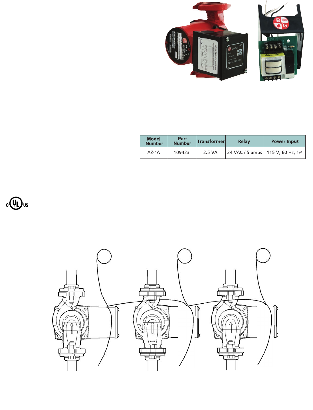
RELAYS ZONETROL II AZ-1A™ Snap-On Pump Relay
Description
The ZONETROL II AZ-1A snap on relay box is an easy to install single zone
pump controller that mounts directly on any Bell & Gossett wet rotor circulator
NRF/NBF or Series PL booster. The AZ-1A turns the pump and boiler ON as
thermostat calls for heat. Using the wire nuts provided with the package, the
AZ-1A is quickly assembled onto any NRF/NBF or 1/12 to 1/6 HP Series PL.
The clearly marked TT terminals for the thermostat and the XX isolated end
switch terminals make the rest of the hook-up a snap. The AZ-1A can be
daisy-chained together to form a maximum of three zones.
The Bell & Gossett AZ-1A is ideal for any single to three zone pump
application. Or can be used when adding a zone to an existing system. There’s
no more need to have a pump controller hanging on the wall, simply install
the AZ-1A to our NRF/NBF or Series PL circulators and you are finished.
Features
• Snap-on design allows the AZ-1A to be quickly attached
to any B&G wet rotor circulator, reducing your inventory
investment (no need to carry “special” circulators with
factory mounted controllers)
• Clearly marked terminals make for sure, fast wiring of
the system
• Compact design fits in tight locations and presents a
clean professional appearence
• 100% factory tested assures reliable operation
• 5 year warranty — the best in the industry
• Daisy-Chain the AZ-1A relays to form up to three zones
• Can be used on any B&G model NRF, NBF or 1/12 to 1/6
HP Series PL pumps
Dimensions (L x W x H): 2-7/8” X 3-1/4” X 2-5/8”
Approximate Shipping Weight: 0.75 lbs
Specifications
///
ThermostatThermostat Thermostat
115V
AZ—1A
115V
AZ—1A
115V
AZ—1A
The AZ-1A can be
daisy-chained to
form up to three
zones with
simplified wiring.
Low voltage
wiring makes
multiple relay
connections
a snap.
26
• 100% factory tested - guarantees operation
• Five year limited warranty - the best in the business
• Replaceable, standard “ice cube” type relays allow up to 10 amps,
1/3 HP per individual zone
• Selectable priority for domestic hot water
• 30 minute built-in priority timer helps prevent house freeze up - no additional
plug-in cards required
• Automatically resetable fuse protects controller from overload - eliminates
“no heat” call backs due to blown fuse
• Powerful transformers operate up to six zones
• LED diagnostic lights installed internal to the box cover keeps the trouble
shooting in the hands of the authorized heating professionals
• Can be used with “tankless coil” or “cold start” applications
Specifications
Specifications
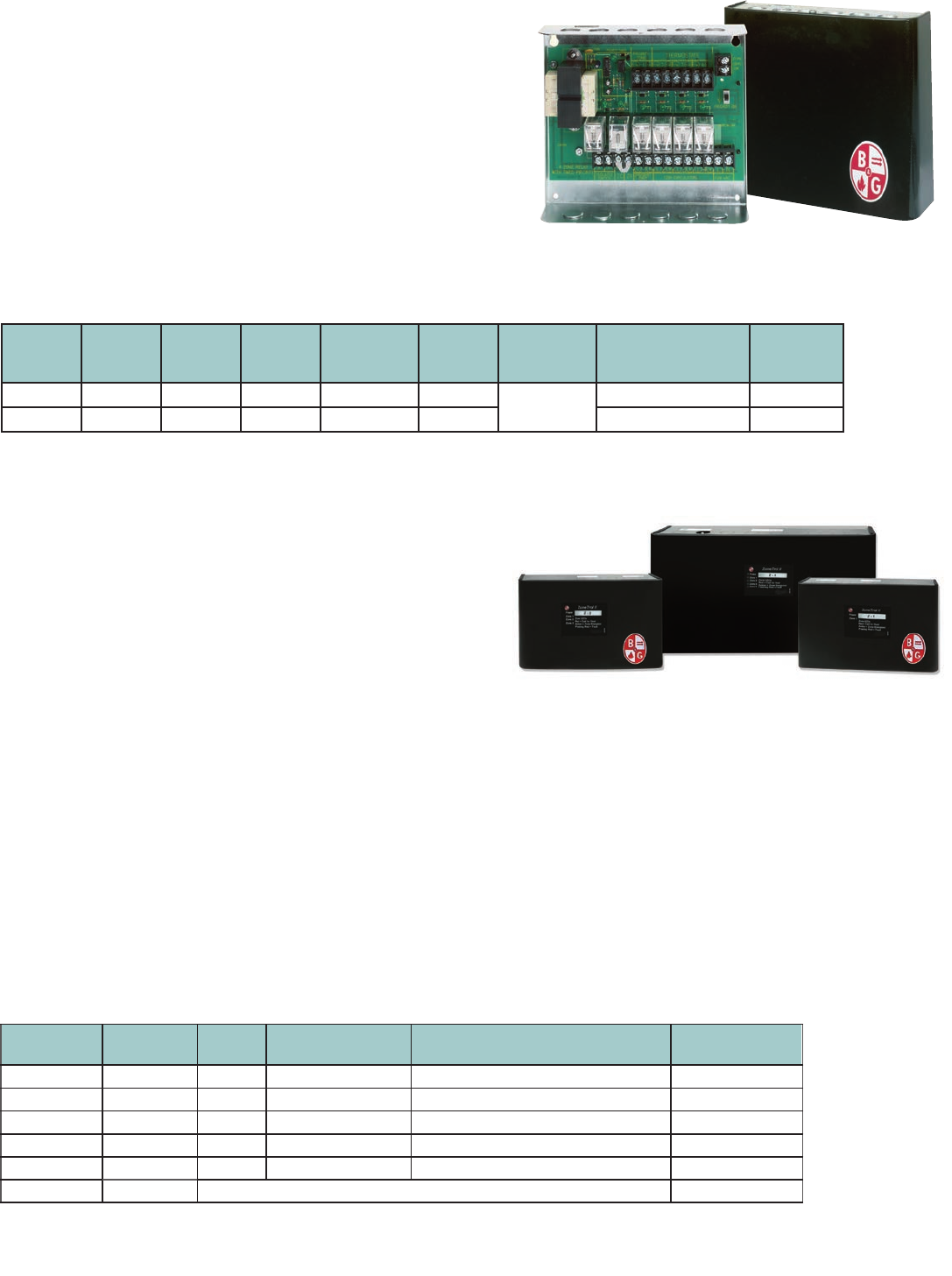
RELAYS ZONETROL™ Switching Relays
for Zoning with Valves
Features
Model
Number
Part
Number Zones Priority
Feature
Transformer
Output
at 24 Volts
Relay
Switching
Action
Each End
Switch Contact
Rating
Dimension
W x H x D (inches)
Approx.
Shpg. Wt.
(lbs.)
ZTV-4 109407 4 yes 40 VA DPDT 5A, 1/8 HP
@ 120VAC
9-1/4 x 7-1/4 x 2-3/4 4.6
ZTV-6 109408 6 yes 75 VA DPDT 11-3/8 x7-1/4 x 3-3/4 6.9
RELAYS ZONETROL II Switching Relays
with Reset Option for Zoning with Pumps
Description
Bell & Gossett’s ZoneTrol II is a ready-to-install controller for hydronic
circulators in residential and light commercial applications. All ZoneTrol II
controllers are UL and cUL listed and feature multi-function LEDs that are
visible without removing the cover for easy start-up and troubleshooting.
All units are compatible with analog and digital 24 VAC thermostats,
including “power stealing” designs. The multi-zone controllers feature an
advanced microprocessor design that provides domestic hot water (DHW)
priority & timer, pump exercise and a post purge timer without the need
for add-on circuit boards or modules.
Four and six zone controllers are field expandable for up to 18 pumps.
* fits 4 and 6 zone controllers only – one required for each slave controller.
Model
Number
Part
Number
Zones Combined Load
(max.) @ 120 VAC
Dimensions W x L x D
Inches (mm)
Weight
Lbs (kg)
Z-1109424 15 amps 6.5 x 5 x 3 (165 x 127 x 76) 2.6 (1.18)
Z-2109425 220 amps 6.5 x 5 x 3 (165 x 127 x 76) 3 (1.36)
Z-3109426 320 amps 6.5 x 5 x 3 (165 x 127 x 76) 3.1 (1.4)
Z-4109427 420 amps 13.5 x 8.25 x 3.25 (343 x 210 x 83) 7.3 (3.3)
Z-6109430 613.5 x 8.25 x 3.25 (343 x 210 x 83) 7.5 (3.4)
ZC-11* 109454 Communication cable for connection of multiple controllers0.1 (0.05)
20 amps
Standard Features (multiple zone controllers only)
• Priority: Enables DHW zone to have priority over heating zones for limited period of time. User adjustable settings include OFF (disables priority
functionality), 30 minutes and 60 minutes.
• Post Purge Timer: Circulator(s) will continue to run for 90 seconds after thermostat opens and allows additional extraction of BTUs from high
mass boilers. User adjustable settings are OFF and ON.
• Exercise: Runs each circulator for 10 seconds after each 72 hours of inactivity. User adjustable settings are ON and OFF.
• Expandability: 4 and 6 zone controllers can easily be connected via a ZC-11 cable to accommodate systems consisting of up to 18 circulators.
• Five-year Warranty
The next generation of zone controllers
from Bell & Gossett brings 21st century
technology to residential controls.
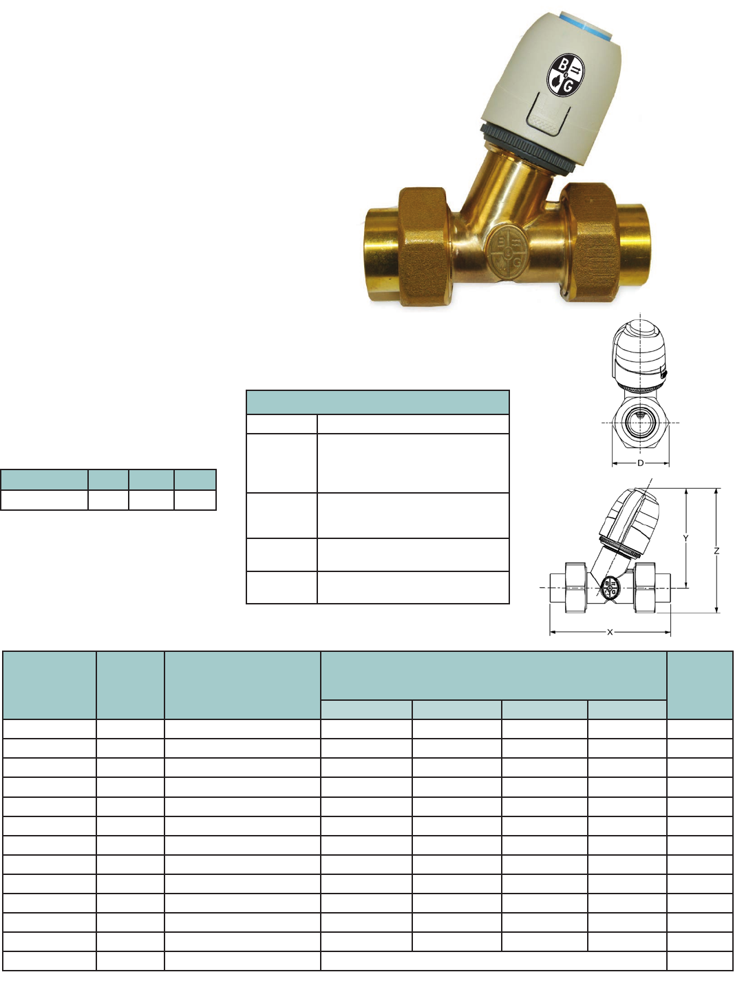
27
VALVES Snap Zone™ Valve
Specifications
Model Number Part Number Description Dimensions, in inches (mm) Shipping
Weight,
lbs (kg)
D X Y Z
SZV-050S-4WE 109500 ½” SWT Zone Valve, 4 Wire 1.59 (40.3) 3.48 (88.5) 3.55 (90.2) 4.24 (107.7) 1.4 (0.6)
SZV-075S-4WE 109501 ¾” SWT Zone Valve, 4 Wire 2.02 (51.3) 4.28 (108.7) 3.55 (90.2) 4.42 (112.5) 1.4 (0.6)
SZV-100S-4WE 109502 1” SWT Zone Valve, 4 Wire 2.24 (56.9) 4.28 (108.7) 3.55 (90.2) 4.52 (114.9) 1.4 (0.6)
SZV-050N-4WE 109506 ½” NPT Zone Valve, 4 Wire 1.59 (40.3) 3.58 (91.0) 3.55 (90.2) 4.24 (107.7) 1.4 (0.6)
SZV-075N-4WE 109507 ¾” NPT Zone Valve, 4 Wire 2.02 (51.3) 4.18 (106.1) 3.55 (90.2) 4.42 (112.5) 1.4 (0.6)
SZV-100N-4WE 109508 1” NPT Zone Valve, 4 Wire 2.24 (56.9) 4.44 (112.7) 3.55 (90.2) 4.52 (114.9) 1.4 (0.6)
SZV-050S-000 109512 ½” Sweat Body 1.59 (40.3) 3.48 (88.5) – – 1.0 (0.4)
SZV-075S-000 109513 ¾” Sweat Body 2.02 (51.3) 4.28 (108.7) – – 1.0 (0.4)
SZV-100S-000 109514 1” Sweat Body 2.24 (56.9) 4.28 (108.7) – – 1.0 (0.4)
SZV-050N-000 109515 ½” NPT Body 1.59 (40.3) 3.58 (91.0) – – 1.0 (0.4)
SZV-075N-000 109516 ¾” NPT Body 2.02 (51.3) 4.18 (106.1) – – 1.0 (0.4)
SZV-100N-000 109517 1” NPT Body 2.24 (56.9) 4.44 (112.7) – – 1.0 (0.4)
SZV-000-4WE 109518 4 Wire Actuator w/ES – 0.4 (0.2)
Description
Snap Zone valves are precision engineered four wire thermoelectrically operated valves
designed for heating and cooling systems. The valve opens and closes based upon the
voltages applied to the actuator. Use the Bell & Gossett Snap Zone Valves to speed
installation time and reduce callback times to customers. The actuator can be installed
or removed at any angle on the adapter ring. The compact design and universality in the
actuator mounting position allows for easy installation in the most difcult positions.
Operating Data
Maximum Operating Temperature: 212°F (100°C)
Minimum Operating Temperature: 32°F (0°C)
Maximum Operating Pressure: 240 PSI
Maximum Differential Closeoff: 60 PSI
Open/Close Speed: 3 min.
Electrical Rating: 24V 60Hz
Power Consumption: 1.8W, 75mA (6 per 40VA)
End Switch Rating: 1.0A @ 24VAC
Materials of Construction
Body: Forged Brass
Bonnet/Packing Box: Brass
Plunger Assembly: Brass, EPDM Seals
Stem: Stainless Steel
Union Nuts: Brass
Tailpieces: Brass
O-Rings: EPDM
Actuator: Polyamide Housing
Cable: PVC
Model Number Naming Convention
SZV Snap Zone Valve
050 Body Size
050 = 0.500”
075 = 0.750”
100 – 1.000”
N Connection Type
S = Sweat Body
N = FNPT Threaded
4W Actuator Type
4W = 4 Wire
E End Switch
E = Endswitch
Snap Zone Size 1/2” 3/4” 1”
Cv 1.8 2.8 2.8
Cv Ratings
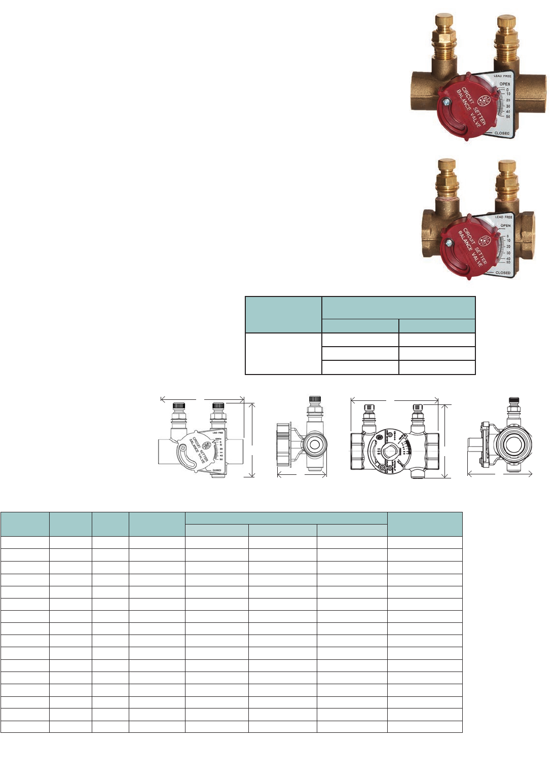
28
BALANCE VALVES Lead-Free* Circuit Setter® Plus
Specifications
Model
Number
Part
Number Size Connection
Type
Dimensions** in Inches (mm) Weight
in lbs. (kg)
A B C
RF-1/2S LF 117410LF 1/2" Sweat 2.91 (73.9) 1.82 (46.2) 2.85 (72.4) 0.6 (0.27)
RF-3/4S LF 117411LF 3/4" Sweat 3.51 (89.2) 2.05 (52.1) 3.10 (78.7) 0.75 (0.34)
CB-1/2S LF 117412LF 1/2" Sweat 2.91 (73.9) 1.82 (46.2) 2.85 (72.4) 1 (0.45)
CB-3/4S LF 117413LF 3/4" Sweat 3.51 (89.1) 2.05 (52.1) 3.10 (78.7) 1.25 (0.6)
CB-1S LF 117401LF 1" Sweat 4.29 (109) 2.33 (59.2) 3.33 (84.6) 2 (0.91)
CB-11/4S LF 117402LF 11/4” Sweat 4.91 (124.7) 3.08 (78.2) 3.69 (93.7) 3.5 (1.6)
CB-11/2S LF 117403LF 11/2” Sweat 5.21 (132.3) 3.27 (83) 3.95 (100.3) 3.8 (1.7)
CB-2S LF 117404LF 2” Sweat 6.31 (160.3) 3.83 (97.3) 4.44 (112.8) 6.2 (2.8)
CB-1/2 LF 117414LF 1/2"NPT 2.94 (74.7) 1.98 (50.3) 3.02 (76.7) 1.25 (0.6)
CB-3/4 LF 117415LF 3/4"NPT 3.06 (77.7) 2.17 (55.1) 3.12 (79.2) 1.5 (0.7)
CB-1 LF 117416LF 1" NPT 3.81 (96.8) 2.47 (62.7) 3.42 (86.9) 2 (0.9)
CB-11/4 LF 117103LF 11/4”NPT 4.41 (112) 3.19 (81) 3.69 (93.7) 3.5 (1.6)
CB-11/2 LF 117104LF 11/2”NPT 4.42 (112.3) 3.37 (85.6) 3.95 (100.3) 3.8 (1.7)
CB-2 LF 117105LF 2” NPT 5.13 (130.3) 3.98 (101.1) 4.44 (112.8) 6.2 (2.8)
CB-21/2 LF 117106LF 21/2”NPT 6.00 (152.4) 4.51 (114.6) 4.83 (122.7) 9 (4.1)
CB-3 LF 117107LF 3” NPT 6.50 (165.1) 5.12 (130.0) 5.44 (138.2) 12 (5.4)
** All dimensions +/-0.125 (3.2 mm) tolerance. Dimensions are subject to change. Not to be used for construction purposes unless certified.
B
END VIEW
1/2"-1"
TOP VIEW
1/2"-1"
A
C
TOP VIEW 1
1/4”-3” END VIEW 1
1/4”-3”
A
C
B
Save time, energy and water with the lead-free
Circuit Setter Plus and Circuit Setter Plus RF.
• Designed for all plumbing and HVAC systems.
• Provides equal ow throughout all circuits to
conserve water and optimize system efciency.
• Calibrated accurate ow control and
measurement.
• Bi-directional design allows any installation
conguration.
• Externally adjustable manual balance
valve for easy adjustment.
• Reduces pump energy requirements.
• Meets or exceeds stringent codes for
potable water.
• Includes memory stop indicator.
• Provides drain option.
• Provides positive shut off and isolation.
• Includes pressure/temperature ports.
Description
The Circuit Setter Plus and Circuit Setter Plus RF
provide the perfect balance of adjustability and
efciency for potable water and HVAC systems.
They are precisely calibrated for use as a
presettable balance valve, variable orice ow
meter and positive shut-off service valve. They
are also designed for optimal system efciency
and water conservation. The Circuit Setter Plus
and Circuit Setter Plus RF can provide the perfect
balancing solutions for your potable water and
HVAC system.
Materials of Construction
Body: Brass ASTM B283-C69300*
Ball: 304 Stainless Steel
Seat Rings: Glass and Carbon lled TFE
Readout Valves: Brass with EPT check valves
Stem “O” Ring: EPDM
Maximum Working Pressure
NPT Models: 400 PSIG (2758 kPa)
Sweat Models: See table below
Maximum Operating Temperature
-4°F (-20°C) to 250°F (121°C)
Type Solder
Maximum Pressure Limitations
for 1/2” - 1” with Solder Connections
Pressure PSI kPa Temp ºF (ºC)
95-5
Tin-Antimony
300 (2068) 200 (93)
250 (1724) 225 (107)
200 (1379) 250 (121)
*CSA certied to NSF/ANSI 372 that product contains less than
0.25% lead content by weight on wetted surface.
CB-1LF
CB-1SLF
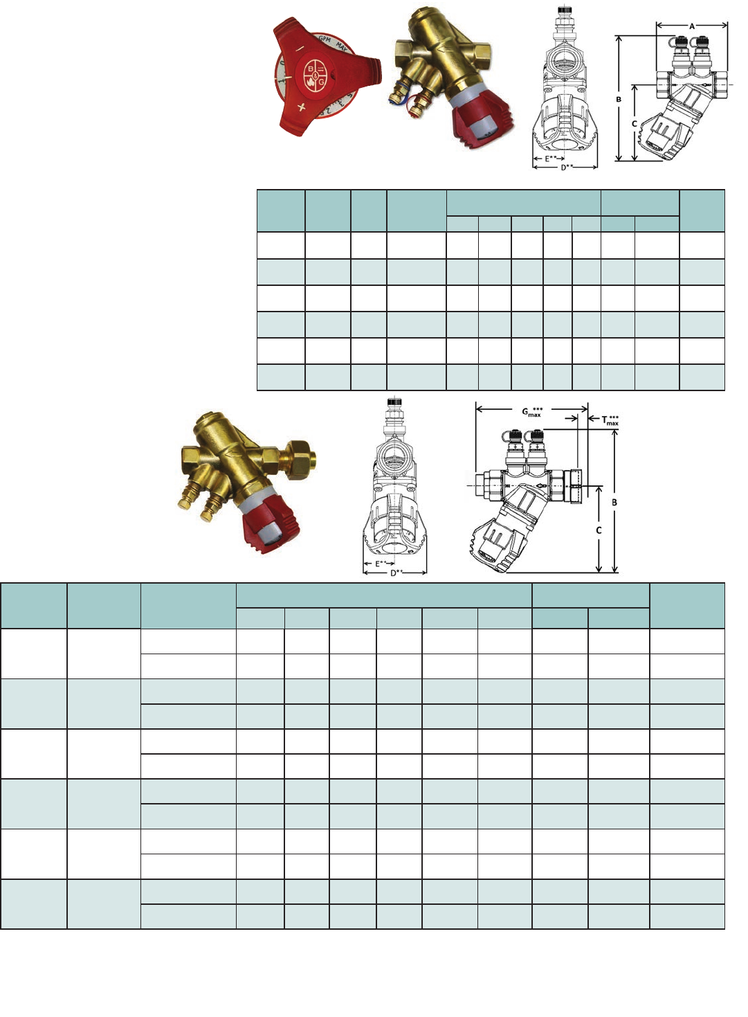
29
BALANCE VALVES Circuit SentryTM Flo-SetterTM
Model
Number
Part
Number Size Connection
Type
DIMENSIONS* IN INCHES (mm) Flow Capacity
in GPM (L/hr) Approx.
Weight
lbs. (kg)
A B C D** E** Min. Max.
FS-1/2 117630 1/2" NPT
Female
2.9
(75)
5.6
(144)
3.4
(87)
2.24
(57)
1.12
(28)
0.26
(60)
4.75
(1,080)
1.1
(0.5)
FS-3/4 117632 3/4" NPT
Female
3.1
(79)
5.6
(144)
3.4
(87)
2.24
(57)
1.12
(28)
0.45
(102)
8.50
(1,930)
1.3
(0.6)
FS-1 117643 1" NPT
Female
3.9
(100)
6.8
(173)
4.3
(110)
2.54
(65)
1.27
(33)
060
(136)
10.56
(2,400)
2.8
(1.3)
FS-1-1/4 117636 1 1/4" NPT
Female
4.0
(104)
7.0
(178)
4.3
(110)
2.54
(65)
1.27
(33)
0.88
(200)
22.01
(5,000)
3.1
(1.4)
FS-1-1/2 117637 1 1/2" NPT
Female
5.4
(138)
7.9
(201)
5.1
(131)
3.60
(92)
1.80
(46)
3.17
(719)
32.58
(7,400)
6.6
(3.0)
FS-2 117638 2" NPT
Female
5.4
(138)
8.1
(207)
5.1
(131)
3.60
(92)
1.8
(46)
3.96
(900)
45.57
(10,350)
7.5
(3.4)
*All dimensions +/- 0.125” (3.2 mm) tolerance. Dimensions are subject to change. Not to be used for construction purposes unless certified.
**Dimension is of maximum width of the handle or body, whichever is greater.
***Includes tailpiece. Measurement of maximum length tailpiece available.
For minimum differential requirements please refer to submittal A-611 on our website. Maximum differential pressure is 58 PSID.
Minimum temperature is 14°F (-10°C) to 248°F (120°C). Maximum operating pressure is 375 PSI.
Model AF Specifications (
includes union tailpiece)
Circuit Sentry Flo-Setter Specifications
Model AF
Circuit Sentry Flo-Setter
Description
The Circuit Sentry Flo-Setter valve is a field adjustable
pressure independent flow limiter that maintains set
flow rates regardless of pressure fluctuations in the
system; eliminates overflow.
• The unique GPM dial is easy to set.
Requires no instruments, charts or wheels
• Saves pump energy and improves coil efficiency
• No minimum straight pipe lengths required
• Integrated pressure / temperature ports included
• Large open flow paths for clog-free operation
• Integrated isolation/shut-off capability
Materials of Construction
Body: DZR Brass
Flow Setting: PA6 20% Glass
Spring: Stainless Steel
Diaphragm: HNBR
O-Rings: EPDM
Maximum Working Pressure
375 PSIG (2585 kPa)
Maximum Operating Temperature
14°F (-10°C) to 248°F (110°C)
Control Range
Maximum 58 PSI (399 kPa) Delta P
Accuracy
+/ - 5%
New GPM dial
NOTE: Model AF valves are configured valves and therefore have no part numbers. They include union tail pieces and can be selected to include optional ball isolation/shut-off valve.
Model
Number
Valve Size
Fixed End
Connection Fixed
End
DIMENSIONS* IN INCHES (mm) Flow Capacity in GPM
(L/hr) Approx. Weight
lbs. (kg)
B C D** E** G Max*** T Max*** Min. Max.
AF-1/2 1/2"
Sweat Female 5.6
(144)
3.4
(87)
2.24
(57)
1.12
(28)
5.6
(142)
1.55
(39)
0.26
(60)
4.75
(1,080)
1.2
(0.5)
NPT Female 5.6
(144)
3.4
(87)
2.24
(57)
1.12
(28)
5.0
(127)
1.55
(39)
0.26
(60)
4.75
(1,080)
1.2
(0.5)
AF-3/4 3/4"
Sweat Female 5.6
(144)
3.4
(87)
2.24
(57)
1.12
(28)
6.3
(160)
1.55
(39)
0.45
(102)
8.50
(1,930)
1.5
(0.7)
NPT Female 5.6
(144)
3.4
(87))
2.24
(57)
1.12
(28)
5.3
(135)
1.55
(39)
0.45
(102)
8.50
(1,930))
1.5
(0.7)
AF-1 1"
Sweat Female 6.8
(173)
4.3
(110)
2.54
(65)
1.27
(33)
7.6
(193)
2.00
(51)
0.60
(136)
10.56
(2,400)
3.1
(1.4)
NPT Female 6.8
(173)
4.3
(110)
2.54
(65)
1.27
(33)
6.4
(163)
2.00
(51)
0.60
(136)
10.56
(2,400)
3.1
(1.4)
AF-1-1/4 1 1/4"
Sweat Female 7.0
(178)
4.3
(110)
2.54
(65)
1.27
(33)
7.9
(201)
2.00
(51)
0.88
(200)
22.01
(5,000)
3.6
(1.6)
NPT Female 7.0
(178)
4.3
(110)
2.54
(65)
1.27
(33)
6.7
(170)
2.00
(51)
0.88
(200)
22.01
(5,000)
3.6
(1.6)
AF-1-1/2 1 1/2"
Sweat Female 7.9
(201)
5.1
(131)
3.60
(92)
1.8
(46)
10.6
(269)
2.52
(64)
3.17
(719)
32.58
(7,400)
7.6
(3.4)
NPT Female 7.9
(201)
5.1
(131)
3.60
(92)
1.8
(46)
9.2
(234)
2.52
(64)
3.17
(719)
32.58
(7,400)
7.6
(3.4)
AF-2 2"
Sweat Female 8.1
(207)
5.1
(131)
3.6
(92)
1.80
(46)
11.7
(297)
3.14
(80)
3.96
(900)
45.57
(10,350)
8.7
(3.9)
NPT Female 8.1
(207)
5.1
(131)
3.6
(92)
1.80
(46)
9.7
(246)
3.14
(80)
3.96
(900)
45.57
(10,350)
8.7
(3.9)
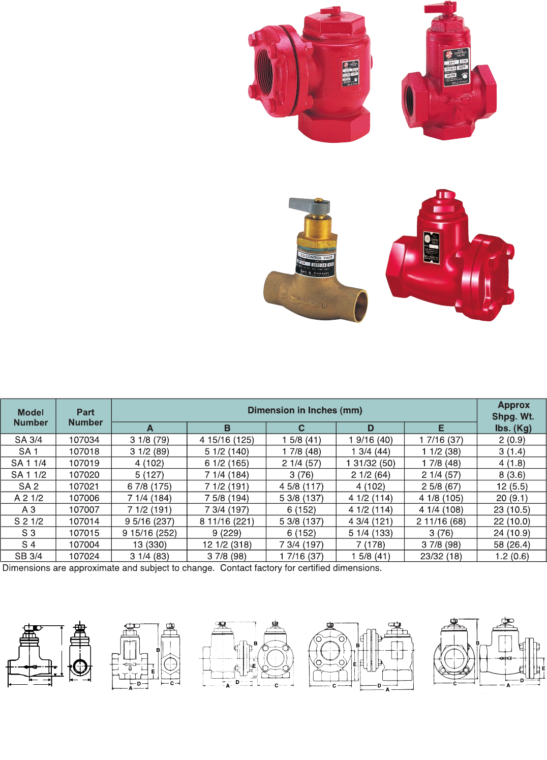
30
VALVES Flo-Control™ Valves
D
B
C
A
E
Angle Pattern
2-1/2”, 3”
Straight-Angle Pattern
3/4”, 1”, 1-1/4”, 1-1/2”, 2”
Straight Pattern
2-1/2”, 3”, 4”
Bronze Straight
Pattern 3/4”
Sizes 3/4”
Bronze Straight Valve
Sizes 3/4”, 1”, 1-1/4”, 1-1/2”
Straight Angle Valves
Sizes 2-1/2”, 3”, 4”
Straight Valves
Sizes 2”
Straight Angle Valves
Sizes 2-1/2”, 3”
Angle Valves
Description
Flo-Control valves prevent gravity flow in forced hot water
systems, and permit summer/winter operation of indirect
water heaters.
Features
• Combination straight/angle configurations in sizes
3/4” to 2” for ease of installation.
• Removable cap allows easy cleaning and service
without removing pipe connections.
• Manual operating position for vertical lift disc to
permit gravity circulation.
Operating Data
Maximum Working Pressure: 125 PSIG (862 kPa)
Maximum Operating Temperature: 250°F (121°C)
Specifications
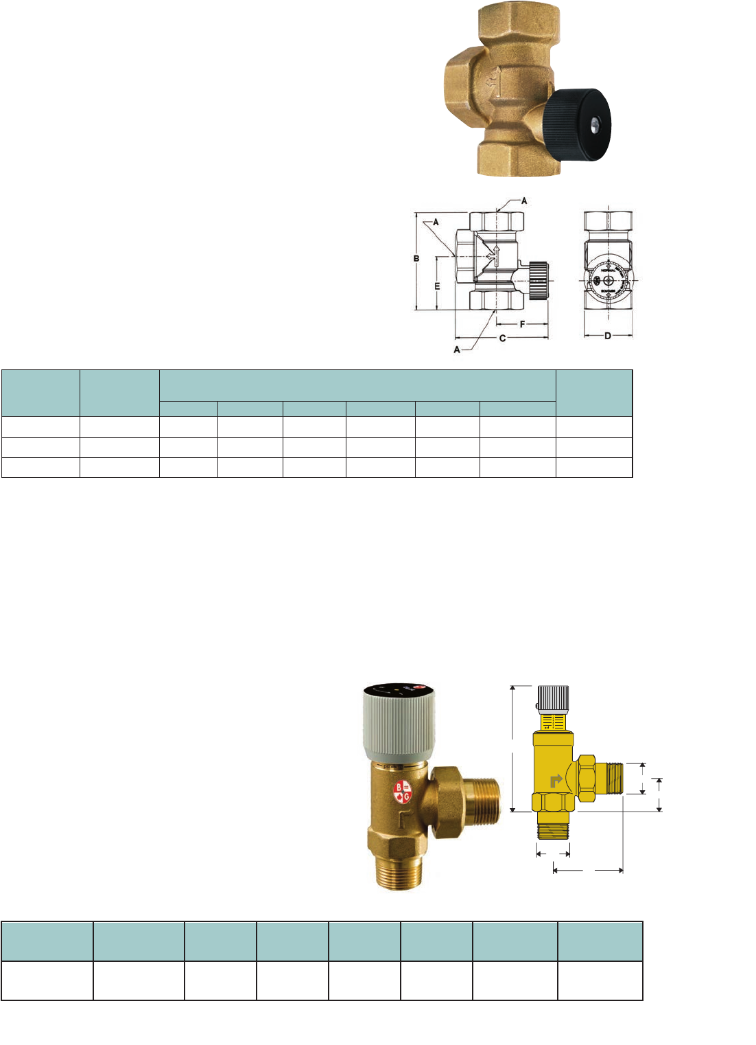
Dimensions — Inches (mm)
Model Part
Number Number
Approx.
Shpg. Wt.
lbs. (Kg)
HT-3/4
HT-1
HT - 1-1/4
107035
107037
107038
1.3 lbs. (0.6)
1.2 lbs. (0.5)
1.8 lbs. (0.8)
1-11/16" (43)
1-11/16" (43)
1-7/8" (48)
Do not use for construction. Dimensions are approximate and subject to change. Contact factory for certified dimensions.
ABCDEF
3/4" NPTF
1" NPTF
1-1/4" NPTF
3-3/16" (82)
3-5/8" (93)
4" (101)
3" (76)
3-3/16" (82)
3-11/16" (93)
1-9/16" (40)
1-9/16" (40)
1-11/16" (43)
1-3/4" (44)
1-15/16" (50)
2-1/4" (57)
31
VALVES Hydrotrol
™
Flow Control Valves
Operating Data
Maximum Working Pressure: 150 PSI (10 bar)
Maximum Operating Temperature: 250°F (121°C)
Materials of Construction
Body: Brass
Internal Components: Non-Ferrous
Specifications
Description
The Hydrotrol (HT) flow control valve is used to prevent overheating of zones
due to gravity flow in hydronic heating systems and will permit summer-winter
operation of indirect water heater. The HT valve allows fluid to pass when the
system or zone pumps start. When the system or zone pumps are not operating,
the HT valve remains closed, preventing gravity circulation. The HT valves are
designed with a 1/2 turn knob that can be manually opened when draining
the system or for bypass purposes. The HT valve can be installed in either the
horizontal or vertical orientation.
VALVES DB–Differential Bypass Valve
Specifications
D
A
B
A
C
Description
The differential bypass valve is used in systems where heating
loads may be excluded from the circuit as zone valves close.
It controls the excess flow in the system by acting as a bypass
while ensuring adequate flow to the remaining open circuits.
The differential bypass valve helps reduce velocity noise
caused by excess flow through the circuits while maintaining
the pump head at a constant value.
Operating Data
Maximum Working Pressure: 150 PSIG (1,034 kPa)
Maximum Operating Temperature: 230°F (110 °C)
Adjustment Range: 2 to 10 PSI
Materials of Construction
Valve Body: Brass
Seals: EPDM
Spring: Stainless Steel
Knob: ABS
For hydronic systems utilizing zone valve
• Controls excess flow in the system when there
is reduction in demand
• Available in 3/4” connection
• All brass body with non-ferrous internals
Model
Number
Part
Number
A
(mm)
B
(mm)
C
(mm)
D
(mm)
Connection
Type
Weight (LB)
DB-3/4 113247 3/4”
(19)
2-5/16”
(59)
1”
(26)
4”
(104)
M
NPT
1

Part
Number
Model
Number
Part
Number
Model
Number
Description
Reducing valves fill the system
to a preset pressure for optimum
performance.
Features
• Fast fill feature reduces
start-up time and labor.
• Low inlet pressure check valve
helps prevent loss of system
pressure if the supply water
drops below system pressure.
• Convenient cleanable strainer
is designed to prevent dirt and
sediment from entering the
system.
• Union connection available
with 1/2” male NPT thread and
1/2” female sweat tail-piece for
fast, flexible system connection.
• Lead-Free brass body construction
is ideal for potable water systems.
VALVES Pressure Reducing Valves
32
ASME Safety Relief Valves
Model
Number Body
Specifications
Description
ASME Safety Relief Valves
p
rotect fired and unfired hot water
vessels against hazardous operating pressures.
Features
• Engineered in accordance with Section IV of the ASME
boiler and pressure code for heating boilers with capacities
certified by the National Board of Boiler and Pressure
Vessel Inspectors.
• Offer the highest BTUH ratings available on the market
today for valves in their class (790,000 to 5,999,000 BTUH)
• EPDM diaphragm operated (cast iron models) and
diaphragm assisted (bronze models) have an effective
area approximately 5 times greater than conventional
“pop-type” relief valves to help overcome the effects of fouling.
• Low differential between opening and closing pressures
helps to prevent conditions under which system water
might flash to steam and cause hammering.
Models 3301 & 4100
Iron Body Valves
Nos. 3301 & 4100 Nos. 790 & 1170
Models 790 & 1170
Bronze Body Valves
F-3TU
FB-38 FB-38TU B-38 B-38TU
Specifications for Pressure Reducing Valve
Specifications for Combination “Dual Units”
PRV's
PRESSURE REDUCING VALVES
Factory Adjustable
Body Conncection Setting Range Dimensions in Inches (mm)
Material Size - Inches (PSIG) (PSIG) ABCD
B-38 110190 1/2 3 1/16 (78) 4 13/16 (122) 3 11/16 (94) 1 1/8 (29)
B7-12 110196 3/4 NPT 3 (76) 4 31/32 (126) 3 21/32 (93) 1 5/16 (33)
B-38TU 110191 1/2 Union* 12 10 - 25 4 31/32 (126)
FB-38 110192 Brass 1/2 NPT 3 1/16 (78) 4 13/16 (122) 3 11/16 (94) 1 1/8 (29)
FB-38TU 110193 1/2 Union* 4 31/32 (126)
6 110194 1/2 3 1/16 (78)
7 110195 3/4 NPT 45 25 - 60 3 (76) 4 31/32 (126) 3 21/32 (93) 1 5/16 (33)
* Models ending in "TU" feature 1/2" sweat/NPT union connection
COMBINATION "DUAL UNITS"
Connection in Inches Dimensions in Inches (mm) Approx.
Component Body Between Overall Shpg. Wt.
Model
Number
Part
Number Valves Material Boiler Fill Connections Height lbs. (Kg)
Relief
8
110199LF
B-38 1/2 NPT 6 7/16 (164) 4 (1.8)
5 3/8 (137)
Relief
F-3 110197LF FB-38 1/2 NPT 1/2 NPT 6 7/16 (164) 3 3/4 (1.7)
Relief 1/2 Union
F-3TU 110198LF FB-38TU
Lead-Free
Brass
NPT/Sweat 8 5/8 (219)
6 (152)
4 (1.8)
PRESSURE SETTING:
Relief 30 PSI
Reducing 12 PSI standard; field adustable range: 10 - 25 PSI
Maximum operating temperature 225°F (107°C) - Maximum operating pressure 125 PSIG (862 kPa)
Approx.
Shpg. Wt.
lbs. (Kg)
1 3/4 (0.8)
2 1/4 (1.0)
2 (0.9)
1 3/4 (0.8)
2 (0.9)
1 3/4 (0.8)
2 1/4 (1.0)
Lead-Free Brass meets NSF 372 certification
Model
Number
Part
Number
Models ending in TU feature 1/2” sweat/NPT union connection.
NSF/ANSI 372
*CSA certied to NSF/ANSI 372 that product contains less than 0.25% lead content by
weight on wetted surface.
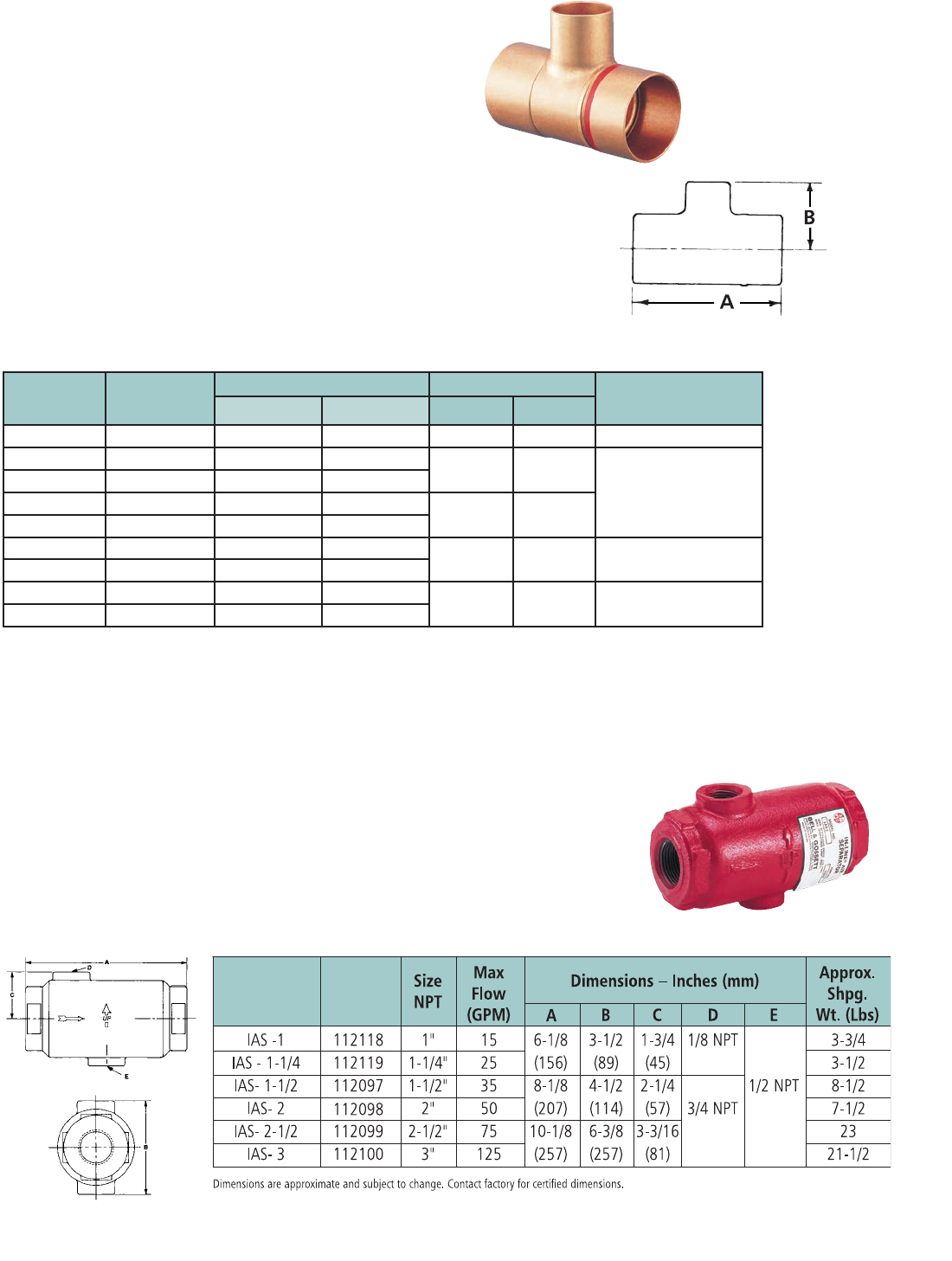
33
AIR SEPARATORS Inline Air Separator
ACCESSORIES Copper Red Ring Monoflo® Fittings
Specifications
Description
Copper Red Ring Monoflo Fittings let you use
a single pipe to serve as both supply and return main.
Features
• Connect risers to the main, assuring proper diversion of water
to each heating unit regardless of type and its position
in the system.
• Recommended for most installations including cast iron
non-ferrous base boards, free-standing radiation or convectors.
• Only one fitting is needed for most installations for adequate
diversion for upfeed radiation. For most applications, a second
fitting can be used if higher resistance is required.
Operating Data
Maximum Working Pressure: 150 PSIG (1,034 kPa)
Maximum Operating Temperature: 300°F (149°C)
Operating Data
Maximum Working Pressure: 175 PSIG (1,207 kPa)
Maximum Operating Temperature: 300°F (149°C)
Materials of Construction
One Piece Cast Iron
Model
Number
Part
Number
Specifications
Description
The B&G In-Line Air Separator
is specificaly designed to
efficiently separate air from
circulating water in hydronic
heating and cooling systems to
assure a quiet operation.
Part Number Size
Inches
Dimensions-Inches (mm)* Cv Ratings** Approx. Shpg.
Wt. lbs. (Kg)
A B 1 FTG 2 FTG
108119 3/4 x 1/2*** 2-7/32 (56) 1 (25) 4.2 –– 1/4 (0.1)
108120 1 x 1/2 2-9/16 (65) 1-5/32 (30) 14.5 8.7
1/2 (0.2)
108121 1 x 3/4 2-3/4 (70) 1-3/8 (35)
108122 1-1/4 x 1/2 2-3/4 (70) 1-7/32 (31) 24.0 15.5
108123 1-1/4 x 3/4 2-27/32 (72) 1-3/8 (35)
108124 1-1/2 x 3/4 3-3/32 (78) 1-11/16 (42) 39.0 25.0 1-1/4 (0.6)
108125 1-1/2 x 1 3-3/8 (86) 1-11/16 (42)
108126 2 x 3/4 3-1/2 (89) 1-27/32 (47) 80.0 55.0 1-3/4 (0.8)
108127 2 x 1 3-13/16 (97) 2-1/32 (52)
* Do not use for construction. Dimensions are approximate and subject to change. Contact factory for certied dimesions.
** With Side Branch plugged.
*** Return only.
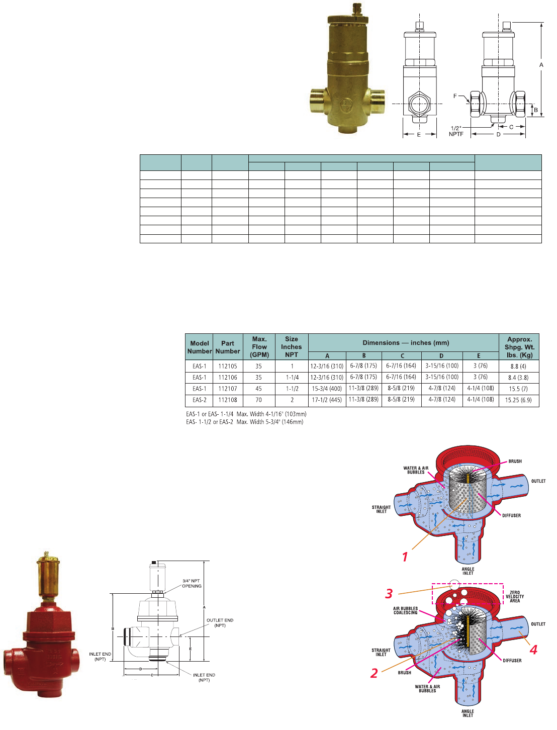
34
Enhanced Air Separator
AIR SEPARATORS EASB-Jr Enhanced Air Separator
Description
Bell & Gossett’s Model EAS Enhanced Air
Separator is a patented, innovative design in air
separators. It has been engineered to remove
entrained air from hydronic heating and cooling
systems providing far superior air removal
compared with other devices available today.
The EAS is ideal for residential, institutional
and light commercial applications.
Operating Data
Maximum Working Pressure: 150 PSI (10.3 bar)
Maximum Operating Temperature: 250°F (121°C)
Materials of Construction
Body & Cap: Cast Iron
Internals: Stainless Steel
3/4” Large Capacity Air Vent: Brass Body Nonferrous Internals
Operating Data
Maximum Working Pressure: 150 PSI (10 bar)
Maximum Operating Temperature: 250°F (121°C)
Materials of Construction
Body & Cap: Brass
Coalescing Medium: Stainless Steel
Venting Mechanism: Non-Ferrous
Specifications
Specifications
Dimensions & Weights
Description
Bell & Gossett’s Model EASB-
JR Enhanced Air Separator
automatically removes entrained
air bubbles in hydronic systems. As
fluid enters the EASB-JR, the velocity
is decreased creating a low pressure
area. The small bubbles are released
from fluid and then collected on the
coalescing medium. As the bubbles
coalesce, they rise to the top of the
air separator where they are released
to atmosphere through the built-in
automatic air vent. The air separator
has a bottom 1/2” NPT connection
to accommodate a B&G diaphragm
expansion tank. The compact design
and brass body construction make
the EASB-JR ideal for residential
and commercial hydronic heating
systems.
How It Works
1 As system fluid enters
through the inlet, (either
straight or angle) the diffuser
distributes flow evenly across
the stainless steel, wire
brush-like medium.
2 Air bubbles, even micro air
bubbles, stick to the brush
filaments.
3 Trapped air rises above the
diffuser through a baffle (not
pictured), where the air is
then released through
an opening on top.
4 Deaerated water then goes
back into the system.
Model
)mm( sehcnI ni noisnemiDtraP
Approx. Shpg. Wt.
Number Number Size ABCDEF Lbs. (Kg)
EASB-3/4JR 112111 3/4"NPT 67/8(175) 15/8(41) 113/16 (46) 35/8(92)2
1/4(57) 3/4"NPTF 2.5 (1)
EASB-3/4S JR 112114 3/4" Sweat 67/8(175) 15/8(41) 113/16 (46) 35/8(92)2
1/4(57) 3/4" Sweat2.5 (1)
EASB-1 JR 112112 1" NPT6
7/8(175) 15/8(41) 113/16 (46) 35/8(92)2
1/4(57)1"NPTF 2.5 (1)
EASB-1S JR 112115 1" Sweat 67/8(175) 15/8(41) 113/16 (46) 35/8(92)2
1/4(57)1" Sweat 2.5 (1)
EASB-11/4JR 112113 11/4" NPT 71/2(191) 17/8(48) 25/16 (59) 45/8(117) 31/8(79)1
1/4"NPTF 4 (1.8)
EASB-11/4S JR 112116 11/4" Sweat 71/2(191) 17/8(48) 25/16 (59) 45/8(117) 31/8(79)1
1/4" Sweat 4 (1.8)
EASB-11/2JR 112117 11/2" NPT 71/2(191) 17/8(48) 25/16 (59) 45/8(117) 31/8(79)1
1/2"NPTF 4 (1.8)
EASB-2 JR 112464 2" NPT 71/2(191) 2 (51) 21/2(64) 5 (127)3
1/8(79)2"NPTF5 (2.3)
Dimensions are approximate and subject to change. Contact factory for certified dimensions.
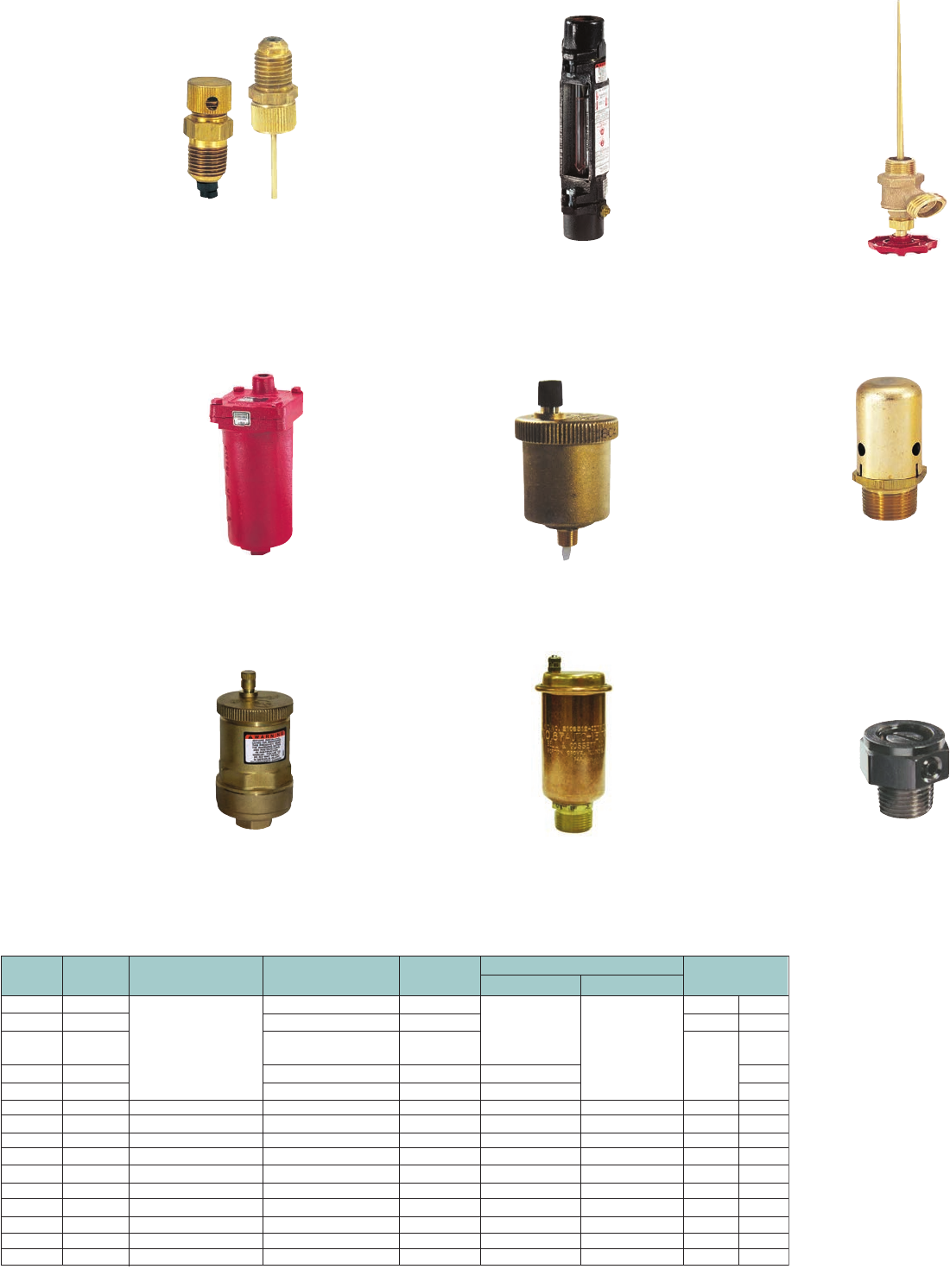
35
HYDRONIC SPECIALTIES
AIR VENTS
Approx. Shpg.
Wt. (Lbs)
Carton Of
1.8
Part
Number
Model
Number
Maximum
Pressure Temperature
Dimensions
(W x H)
System
Connection
Description
107A
7
67
87
97
RV-125A
26
4V
TB-1
TB-3/4
1/8" P/T
1/4" P/T
113076
113001
113020
113021
113222
113100
113075
113055
127002
127001
G97030
V58050PK
High Capacity Air Vent
Automatic Air Vent
Readout Valve
Vacuum Breaker
Manual Air Vent
Balance Valve
Balance Valve
Readout Valve
Readout Valve
3/4" NPTF
1/8" NPTF
1/8" NPTM
Combination
3/4" NPTM 1/2" NPTF
1/8" NPTM
1/8" NPTM
3/4" NPTM
1/8" NPTM
1" NPTF
3/4" NPTF
1/8" NPTM
1/4" NPTM
4-1/2" x 9-5/8"
1-1/2" x 3-3/16"
2-1/4" x 4-3/4"
1-7/8" x 3-1/8"
1-1/8" x 9/16"
1-1/4" x 3"
5/8" x 5/8"
2" x 9-1/4"
2" x 9-1/4"
1-1/8" x 1-1/4"
1-1/4" x 1-1/4"
2-3/16" x 4-1/16"
150 PSIG
75 PSIG
35 PSIG
150 PSIG
300 PSIG
150 PSIG
125 PSIG
300 PSIG
250ºF
240ºF
250ºF
300ºF
250ºF
250ºF
240ºF
10
.5
.25
.61
4
3
2
26
26
.5
.1
1
1
50 pairs
6
48
6
6
1
1
240 PSIG
300 PSIG
125 PSIG
250ºF
250ºF
1.8
98 113246 3/4" NPTM 4-1/2" x 9-5/8" 250ºF
DT-2
RP-250B
113041
113102
Drain-O-Tank
Readout Probe
1/2" NPTM
N/A
2-1/4" x 6-5/16"
2" x 5/8"
125 PSIG
250ºF
240ºF .67
1
1
6 pairs
300 PSIG
TB– Thermoflo® Balancer
A device for instant visual balancing
of hot or cold water flows. With a
B&G Thermoflo balancer installed
in each circuit or zone, the entire
system can be quickly balanced to
meet original design calculation.
No. TB-3/4”- Capacity 1 to 5 GPM.
No. TB-1”- Capacity 2 to 10 GPM.
125 PSIG Working Pressure —
250ºF Maximum Operating
Temperature
DT-2 Drain-O-Tank®
Air Charger
The Drain-O-Tank Air Charger offers a
sure, quick way to recharge a water-
logged compression tank.
125 PSIG Working Pressure —
240ºF Maximum Operating
Temperature
Model No. 107A High
Capacity Air Vent
A rugged High Capacity Air Vent
designed to purge free air from
liquid systems at operating
pressures up to 150 PSIG.
The Model 107A Air Vent has
a cast iron body and bonnet,
with stainless steel, brass and
EPDM internal components
and is suitable for a maximum
operating temperature of
250ºF. The Air Vent has a 3/4”
NPT inlet and 3/8” NPT outlet.
No. 98
A high capacity automatic air
vent that is designed to remove
air in closed loop systems.
Materials of construction: Brass
body with non-ferrous internals.
Maximum Working
Pressure: 150 PSI. Maximum
Operating Temperature: 250ºF
No. 97 Automatic
Air Vent
A float type vent designed to
vent troublesome air from
hydronic heating systems. The
brass body and the non-ferous
internals provide years of reliable
service. The compact design
(3-1/8” x 1-7/8”) and high operating
pressure/temperature (240ºF @ 150 PSIG)
limitations make the No. 97 a must in any
hydronic heating system.
No. 87, 67 and 7
Automatic Air Vents
Designed to vent the
accumulation of troublesome
air wherever it can be trapped.
These non-ferrous automatic
air vents are 4-3/4” x 2-1/4”,
3-3/16” x 1-1/2” and 4-1/16”
x 2-3/16” (height and width),
respectively, and are rated for
a maximum operating temperature of
240ºF at pressures of 150, 35 and 75 PSI,
respectively. The No. 87 has a combination of
1/2” FPT/3/4” MPT connection, whereas No’s. 67
and 7 have 1/8” MPT, and FPT connections.
No. 26 Vacuum Breaker
Designed to protect closed
vessels and piping systems
against collapse when the
induced vacuum exceeds design
conditions. When used on
steam heating systems, the No.
26 Vacuum Breaker controls
induced vacuum, permitting normal
return of condensate to the boiler.
Adjustable range 1/4” to 20” (mercury)
vacuum. Factory set to 4” — 240 PSIG
Maximum Working Pressure —
300ºF Maximum Operating
Temperature
No. 4V “Coin-Operated”
Air Vent
Specially designed for the new
types of radiators. An important
feature is that it projects only
slightly, being almost flush with
the radiator. 150 PSIG Working
Pressure — 250ºF Maximum
Operating Temperature
RV-125A Readout Valve and
RP-250B Readout Probe
The RV-125A is designed
for use wherever pressure
tappings are required to
monitor flow or pressures.
The Readout Valve is fitted
with an EPT insert which
incorporates a unique check
valve feature designed
to check flow when the
Readout Valve is not being
used to monitor flow. Use companion RP-250B
Readout Probes with the RV-125A Readout
Valve. 300 PSIG Working Pressure —
250ºF Maximum Operating Temperature
RP-250
RV-125
Specifications
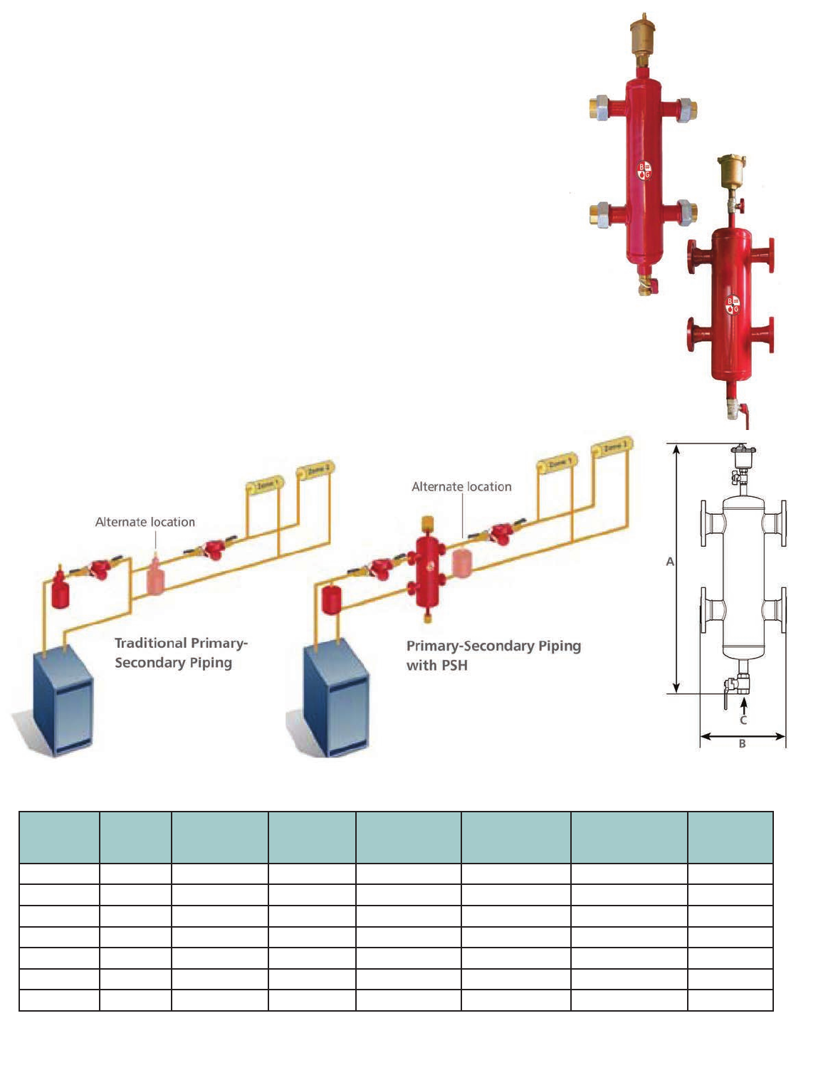
36
ACCESSORIES PSH - Primary/Secondary Header
Description
The B&G low-loss header, Model PSH, is a
combination air separator and manifold that
creates independent primary and secondary
circuits. The B&G Model PSH is equipped
with a purge valve allowing the user to
remove any debris deposited on the bottom
of the vessel and an air vent releasing
trapped air in the system. The insulation,
which is provided as standard, prevents
water vapors entering from the outside and
eliminates the formation of condensate on
the PSH body.
Operating Data
With Insulation:
Working Pressure: 150 PSI
Operating Temperature Threaded: 32°- 210°F
Operating Temperature Flanged: 32°- 220°F
Without Insulation:
Working Pressure: 150 PSI
Operating Temperature Threaded & Flanged: 32°-230°F
Materials of Construction
Body: Steel
Air Vent: Brass
Drain Valve: Brass
Insulation-Threaded: PEX
Insulation-Flanged: Polyurethane Foam
Connection
1”, 1-1/4” and 1-1/2” Female NPT
2”, 2-1/2”, 3” and 4” ANSI 150 CLASS Flange
Specifications
Model
Number
Part
Number
Connection Size
Inches (mm)
Max Flow
GPM (m3/h)
A
Inches (mm)
B
Inches (mm)
C - Drain
Connection Size
Inches (mm) NPT
Weight
LBS (Kg)
PSH-1 112465 1 (25.4) 11 (2.5) 24-3/8 (619) 8-7/8 (225) 1/2 (12.7) 6.0 (2.7)
PSH-1.25 112466 1-1/4 (31.75) 18 (4) 26-3/4 (679) 9-3/4 (248) 1/2 (12.7) 8.3 (3.8)
PSH-1.5 112467 1-1/2 (38.1) 26 (6) 28-1/3 (719) 11-1/8 (282) 1/2 (12.7) 12.6 (5 .7)
PSH-2 112468 2 (50.8) 40 (9) 42 (1069) 13-13/16 (350) 1-1/4(31.7) 78.7 (35.7)
PSH-2.5 112469 2-1/2 (63.5) 80 (18) 42 (1069) 13-13/16 (350) 1-1/4(31.7) 87.7 (39.8)
PSH-3 112470 3 (76.2) 124 (28) 50-3/8 (1279) 18-3/8 (466) 1-1/4(31.7) 108.0 (49)
PSH-4 112471 4 (101.6) 247 (56) 50-3/8 (1279) 18-1/2 (470) 1-1/4(31.7) 116.8 (53)
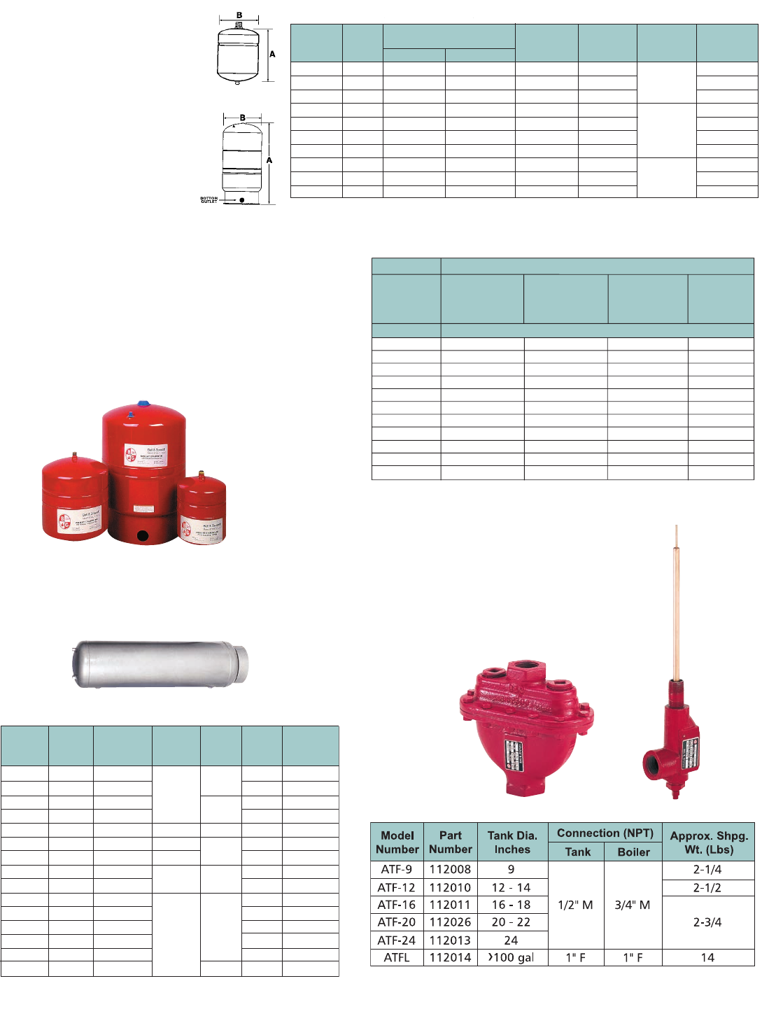
City of
Los
Angeles
Model
Number
HFT-15
HFT-30
HFT-60
HFT-90
HFT-30V
HFT-40V
HFT-60V
HFT-90V
HFT-110V
HFT-160V
5 (2.3)
9 (4.1)
14 (6.4)
23 (10.4)
24 (11)
34 (15.5)
52 (23.6)
64 (29)
89 (40.5)
116 (53)
Approx.
Shpg. Wt.
lbs. (Kg)
Part
Number Tank
Volume Gallons (Liters)
Acceptance
Height (A)
Inches (mm)
Diameter (B)
Inches (mm)
System
Connection
1BN326
1BN327
1BN328
1BN329
1BN330
1BN331
1BN332
1BN333
1BN334
1BN335
2 (7.5)
4.4 (16.6)
7.6 (28.7)
14 (53)
14 (53)
20 (75.7)
32 (121.1)
44 (166.5)
62 (234.6)
86 (325.5)
1.0 (3.7)
2.5 (9.4)
2.5 (9.4)
11.3 (42.8)
11.3 (42.8)
11.3 (42.8)
11.3 (42.8)
34 (128.7)
34 (128.7)
46 (174.1)
12-5/8 (321)
14 (355)
17-1/4 (438)
21 (533)
24-3/4 (629)
32-1/2 (826)
47-1/2 (1207)
36-1/2 (927)
48-1/2 (1232)
46 (1168)
8 (203)
11 (279)
11 (279)
15-3/8 (390)
15-3/8 (390)
15-5/8 (390)
15-5/8 (390)
22 (559)
22 (559)
22 (559)
1/2" NPTM
1" NPTF
1-1/4" NPTF
Materials: Steel Shell Diaphragm
System Connection: Steel
Maximum Operating Temperature=240F (116C); Maximum Working Pressure= 100 PSI (689 kPa);
Standard Factory Precharge=12 PSI (83 kPa)
Model
Number
PT-5
PT-12
PT-25V
PT-30V
PT-42V
PT-60V
PT-80V
PT-180V
PT-210V
5 (2.3)
9 (4.1)
23 (10.4)
25 (11.3)
33 (15)
69 (31.2)
69 (31.2)
92 (41.7)
123 (55.8)
Approx.
Shpg. Wt.
lbs. (Kg)
Part
Number Tank
Volume Gallons (Liters)
Acceptance
Height (A)
Inches (mm)
Diameter (B)
Inches (mm)
System
Connection
1BN317
1BN318
1BN319
1BN320
1BN321
1BN322
1BN323
1BN324
1BN325
2 (8)
4.4 (17)
10.3 (39)
14 (53)
20 (76)
34 (129)
44 (167)
62 (235)
86 (326)
1.0 (4)
3.2 (12)
10.3 (39)
11.3 (43)
11.3 (43)
34 (129)
34 (129)
34 (129)
46.4 (176)
12-5/8 (321)
15 (381)
19-1/4 (489)
23-7/8 (605)
31-5/8 (802)
29-5/8 (752)
36 (914)
46-3/4 (1187)
47-1/4 (1200)
8 (203)
11 (279)
15-3/8 (391)
15-3/8 (391)
15-3/8 (391)
22 (559)
22 (559)
22 (559)
26 (660)
3/4" NPTM
1" NPTF
1-1/4" NPTF
Materials: Steel Shell, Polypropylene Liner, Buty Diaphragm
System Connection: Brass
Maximum Operating Temperature=200F (93C); Maximum Working Pressure= 150 PSI (1,034 kPa);
Standard Factory Precharge=40 PSI (276 kPa)
Larger sizes and ASME constructed models are available.
Code approvals: PT-5, PT-12 PT-25V thru PT-210
37
TANKS HFT Diaphragm Tanks • Expansion Tanks for Hydronic Heating
Airtrol® Tank Fittings
Directs free air to the compression tank. Restricts thermal
circulation to boiler. Establishes initial tank air level.
Allows compression tank size reduction.
Description
Bell & Gossett HFT expansion tanks
are designed to absorb the force
of thermal expansion in hydronic
heating systems. Series HFT tanks
for hydronic heating systems are
available in sizes from 2—86 gallons.
The Series HFT tank is designed
to absorb the force of thermal
expansion of heating water to
maintain proper pressurization in a
closed hydronic system. The heavy
duty butyl diaphragm separates
system water from the air in the tank
preventing water logging problems.
Specifications
HFT-15 thru HFT-90
HFT-30V thru HFT-160V
Model
Number
Part
Number
Capcity
Gallons
Required
Airtrol
Fitting
Approx.
Shpg.
Wt. (Lbs)
Tank
Dia.
Inches
Tank
Length
Inches
15
24
30
40
60
80
100
120
135
175
220
240
305
400
505
116029
116030
116031
116032
116033
116034
116035
116036
116037
116038
116039
116040
116041
116042
116840
15
24
30
40
60
80
100
120
135
175
220
240
305
400
505
ATF-12
ATF-16
ATF-20
ATF-20
ATF-24
ATFL
12
14
16
20
24
30
36
33
51
48
63
72
62
78
65
72
62-1/4
77
84
105-3/4
93
116
50
72
80
104
134
160
186
217
230
320
370
420
482
656
745
Dimensions are approximate and subject to change. Consult factory for certified dimensions.
Part numbers in table above are for paint steel tanks.
Specifications
Specifications
25,000
50,000
75,000
100,000
125,000
150,000
200,000
250,000
300,000
350,000
400,000
HFT-15
HFT-15
HFT-30
HFT-30
HFT-30
HFT-30
HFT-60
HFT-60
HFT-90
HFT-30V
HFT-30V
Finned Tube
Baseboard or
Radiant Panel
Boiler Size Type of Radiation
Convectors
or
Unit Heaters
Radiators
Cast Iron
Baseboard
Cast Iron
BTU/HR Use Tank Model
Net Output
HFT-15
HFT-15
HFT-30
HFT-60
HFT-60
HFT-60
HFT-60
HFT-90
HFT-30V
HFT-30V
HFT-40V
HFT-15
HFT-30
HFT-30
HFT-60
HFT-60
HFT-90
HFT-30V
HFT-30V
HFT-30V
HFT-40V
HFT-40V
HFT-15
HFT-30
HFT-60
HFT-60
HFT-90
HFT-90
HFT-30V
HFT-40V
HFT-40V
HFT-60V
HFT-60V
Assumptions: fill pressure 12 PSI, relief pressure 30 PSI, avg. system temp. 200˚F,
system fluid is water, consult factory with requirements not shown
Operating Data
Maximum Working Pressure: 100 PSI (689 kPa)
Maximum Operating Temperature: 240°F (115°C)
Standard Factory Pre-charge: 12 PSI (83 kPa)
Materials of Construction
Shell: Carbon Steel
Diaphragm: Heavy Duty Butyl Rubber
Connection: Steel
Compression Tanks
Air-tight, ASME constructed. Available in painted steel.
Sizes 15 to 505 gallons. Gauge glass tappings are standard.
Always use with B&G Airtrol Tank Fittings.
Sizing Guideline
* DT-2 Drain-O-Tank Air Charger comes with ATFL model
*
ATFL ATF
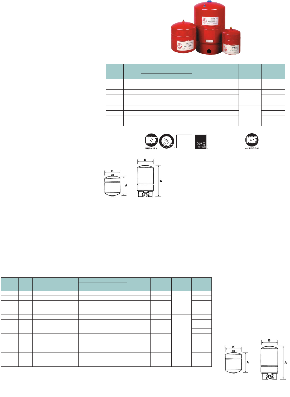
City of
Los
Angeles
Model
Number
PT-5
PT-12
PT-25V
PT-30V
PT-42V
PT-60V
PT-80V
PT-180V
PT-210V
5 (2.3)
9 (4.1)
23 (10.4)
25 (11.3)
33 (15)
69 (31.2)
69 (31.2)
92 (41.7)
123 (55.8)
Approx.
Shpg. Wt.
lbs. (Kg)
Part
Number Tank
Volume Gallons (Liters)
Acceptance
Height (A)
Inches (mm)
Diameter (B)
Inches (mm)
System
Connection
1BN317LF
1BN318LF
1BN319LF
1BN320LF
1BN321LF
1BN322LF
1BN323LF
1BN324LF
1BN325LF
2 (8)
4.4 (17)
10.3 (39)
14 (53)
20 (76)
34 (129)
44 (167)
62 (235)
86 (326)
1.0 (4)
3.2 (12)
10.3 (39)
11.3 (43)
11.3 (43)
34 (129)
34 (129)
34 (129)
46.4 (176)
12-5/8 (321)
15 (381)
19-1/4 (489)
23-7/8 (605)
31-5/8 (802)
29-5/8 (752)
36 (914)
46-3/4 (1187)
47-1/4 (1200)
8 (203)
11 (279)
15-3/8 (391)
15-3/8 (391)
15-3/8 (391)
22 (559)
22 (559)
22 (559)
26 (660)
1" NPTF
1-1/4" NPTF
Larger sizes and ASME constructed models are available.
Code approvals: PT-5, PT-12 PT-25V thru PT-210
Model
Number
HFT-15
HFT-30
HFT-60
HFT-90
HFT-30V
HFT-40V
HFT-60V
HFT-90V
HFT-110V
HFT-160V
5 (2.3)
9 (4.1)
14 (6.4)
23 (10.4)
25 (11.3)
33 (14.9)
43 (19.5)
69 (31.2)
92 (41.7)
123 (55.8)
Approx.
Shpg. Wt.
lbs. (Kg)
Part
Number Tank
Volume Gallons (Liters)
Acceptance
Height (A)
Inches (mm)
Diameter (B)
Inches (mm)
System
Connection
1BN326
1BN327
1BN328
1BN329
1BN330
1BN331
1BN332
1BN333
1BN334
1BN335
2 (7.5)
4.4 (16.6)
7.6 (28.7)
14 (53)
14 (53)
20 (75.7)
32 (121.1)
44 (166.5)
62 (234.6)
86 (325.5)
1.0 (3.7)
2.5 (9.4)
2.5 (9.4)
11.3 (42.8)
11.3 (42.8)
11.3 (42.8)
11.3 (42.8)
34 (128.7)
34 (128.7)
46 (174.1)
12-5/8 (321)
15-1/2 (394)
23 (584)
21 (533)
24-3/4 (629)
32-1/2 (826)
47-1/2 (1207)
36 (914)
46-3/4 (1186)
47-1/4 (1199)
8 (203)
11 (279)
11 (279)
15-3/8 (390)
15-3/8 (390)
15-5/8 (390)
15-5/8 (390)
22 (559)
22 (559)
22 (559)
1/2" NPTM
1" NPTF
1-1/4" NPTF
Materials: Steel Shell Diaphragm
System Connection: Steel
Maximum Operating Temperature=240F (116C); Maximum Working Pressure= 100 PSI (689 kPa);
Standard Factory Precharge=12 PSI (83 kPa)
3/4" NPTM
3/4" NPTF
38
TANKS PT Diaphragm Tanks
Expansion Tanks for Potable Water Systems
Specifications
PT-5 thru PT-12 PT-25V thru PT-210V
WTX Diaphragm Tanks
Description
Bell & Gossett PT expansion tanks are designed to absorb the force of thermal
expansion in domestic potable water systems. Tanks for potable water systems,
Series PT and PTA (ASME construction) are available in sizes from 2—528 gallons.
WTX-10S thru WTX-119S
WTX-2 thru WTX-14
Residential/Light Commercial
Non-ASME Diaphragm Tanks
Operating Data
Maximum Working Pressure:
PT-5 & PT-12: 150 PSI (1035 kPa)
PT-25V thru PT-210V: 100 PSI (689 kPa)
Maximum Operating Temperature: 200°F (93°C)
Materials of Construction
Shell: Carbon Steel
Liner: Polypropylene
Diaphragm: Heavy Duty Butyl Rubber
System Connection: PT-25V thru PT-210V are
stainless steel. All others are brass
Factory Pre-charge: 40 PSI (276 kPa)
Commercial Non-ASME Bladder Tanks
Maximum Working Pressure : 150 PSI (1035 kPa)
Maximum Operating Temperature: 240°F (116°C)
Materials of Construction
Shell: Carbon Steel
Liner: Polypropylene
Diaphragm: Heavy Duty Butyl Rubber
System Connection: Bronze
Factory Pre-charge: 55 PSI (379 kPa)
Specifications
Description
The Series WTX tanks will help protect the pump and pressure switches against short cycling. The potable well
tank delivers adequate water under pressure between pump cycles to meet the required demand. It will provide
economical system operation by minimizing pump starts, extending pump motor life, and saving energy. The
WTX tank will also assist the pump in meeting peak demands.
Operating Data
Maximum Operating Temperature:
200ºF (93ºC)
Maximum Working Pressure:
100 PSI (689 kPa)
Materials of Construction
Shell: Carbon Steel
Liner: Polypropylene
Diaphragm: Heavy Duty Butyl Rubber
System Connection: WTX-2 thru
WTX-14 = Copper Lined Steel Fitting;
all others are Steel with Stainless Steel
Elbow
Factory Pre-charge:
WTX-2, WTX.5 = 18 PSI (124 kPa);
WXT-8 = 28 PSI (193 kPa);
All other WTX tanks = 38 PSI (262 kPa)
Model
Number
WTX-2
WTX-5
WTX-8
WTX-10
WTX-14
WTX-10S
WTX-14S
WTX-20S
WTX-26S
WTX-32S
WTX-34S
WTX-44S
WTX-62S
WTX-81S
WTX-86S
WTX-119S
5 (2.3)
9 (4)
15 (7)
20 (9)
22(10)
23 (10)
25 (11)
33 (15)
36 (16)
43 (20)
61 (28)
69 (31)
92 (41)
103 (47)
123 (56)
166 (75)
Approx.
Shpg. Wt.
lbs. (Kg)
Part
Number Tank
Volume Gallons (Liters)
Acceptance Factor
Height (A)
Inches (mm)
Diameter (B)
Inches (mm)
System
Connection
1BN300
1BN301
1BN302
1BN303
1BN304
1BN305
1BN306
1BN307
1BN308
1BN309
1BN310
1BN311
1BN312
1BN313
1BN315
1BN316
2 (8)
4.4 (17)
7.6 (33)
10.3 (39)
14 (53)
10.3 (39)
14 (53)
20 (76)
26 (98)
32 (121)
34 (129)
44 (167)
62 (235)
81 (307)
86 (326)
119 (450)
0.45
0.55
0.42
1.00
0.81
1.00
0.81
0.57
0.44
0.35
1.00
0.77
0.55
0.41
0.54
0.39
12-5/8 (321)
15 (381)
22-1/4 (629)
17-3/4 (451)
22 (559)
19-1/4 (489)
23-7/8 (605)
31-5/8 (802)
38-1/4 (972)
46-1/2 (1181)
29-5/8 (752)
36 (914)
46-3/4 (1187)
56-3/8 (1432)
47-1/4 (1200)
61-7/8 (1572)
8 (203)
11 (279)
11 (279)
15-3/8 (390)
15-3/8 (390)
15-3/8 (390)
15-5/8 (390)
15-3/8 (390)
15-3/8 (390)
15-5/8 (390)
22 (559)
22 (559)
22 (559)
22 (559)
26 (660)
26 (660)
3/4" NPTM
1" NPTM
1" NPTF
1-1/4" NPTM
System Connection: WTX-2 thru WTX-14 = Copper Lined Steel Fitting; All others = Steel with Stainless Steel Elbow
Factory Pre-Charge: WTX-2. WTX-5 = 18PSI (124kPa); WTX-8 = 28 PSI (193 kPa); All other WTX tanks = 38 PSI (262 kPa)
0.8
1.8
3.1
4.1
5.6
4.1
5.6
8.0
10.5
–
13.7
17.7
24.9
32.6
34.6
47.8
20/40 30/50 40/60
System Drawdown in Gallons
PSIG
0.7
1.5
2.6
3.5
4.8
3.5
4.8
6.8
8.8
10.9
11.6
15
21.1
27.5
29.2
40.5
0.6
1.3
2.2
3.0
4.1
3.0
4.1
5.9
7.6
9.4
10.0
12.9
18.2
23.8
25.3
35.0
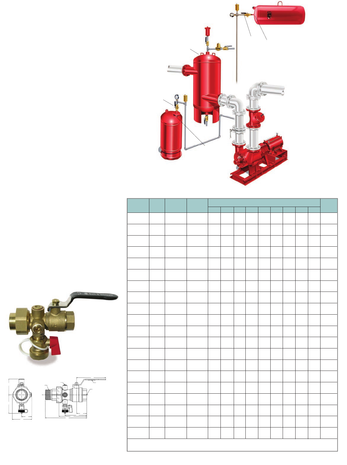
39
VALVES TPV – Tank Purge Valves
Operating Data
Maximum Working Pressure:
400 PSIG (2,758 kPa)
Maximum Operating Temperature:
-4°F (-20°C) to 250°F (121°C)
Materials of Construction
Valve Body: Brass
Ball: Chrome Plated
Ball Seal: PTFE
Stem: Explosion Proof
O-Ring: EPDM
*snoisnemiD knaT metsyS traP ledoM Inch (mm) Approx.
Number Number Connection Connection A B C D E F G H J Weight Lbs.
TPV-1/2SF 113226 1/2” Female 1/2” Female 1.67 2.25 3.15 3.82 0.84 1.60 2.36 1.75 3.34 1.0
SWT NPT (42.4) (57.2) (80.0) (97.0) (21.3) (40.6) (59.9) (44.5) (84.8) (0.5)
TPV-1/2FF 113227 1/2” Female 1/2” Female 1.19 2.00 2.90 3.55 0.84 1.60 2.36 1.75 3.34 1.0
NPT NPT (30.2) (50.8) (73.7) (90.4) (21.3) (40.6) (59.9) (44.5) (84.8) (0.5)
TPV-1/2SM 113228 1/2” Female 1/2” Male 1.29 2.25 3.15 4.73 0.84 1.60 2.36 1.75 3.34 1.0
SWT NPT (32.2) (57.2) (80.0) (120.1) (21.3) (40.6) (59.9) (44.5) (84.8) (0.5)
TPV-1/2FM 113229 1/2” Female 1/2” Male 1.06 2.00 2.90 4.47 0.84 1.60 2.36 1.75 3.34 1.0
NPT NPT (26.9) (50.6) (73.7) (113.6) (21.3) (40.6) (59.9) (44.5) (84.8) (0.5)
TPV-3/4SF 113230 3/4” Female 3/4” Female 1.67 2.85 3.72 4.53 1.06 1.95 2.66 1.89 3.50 1.24
SWT NPT (42.2) (72.4) (94.5) (115.1) (26.9) (49.5) (67.6) (48.0) (88.9) (0.6)
TPV-3/4FF 113231 3/4” Female 3/4” Female 1.19 2.50 3.26 4.06 1.06 1.95 2.66 1.69 3.50 1.24
NPT NPT (30.2) (63.5) (82.8) (103.1) (26.9) (49.5) (67.6) (48.0) (68.9) (0.6)
TPV-3/4SM 113232 3/4” Female 3/4” Male 1.67 2.85 3.72 5.50 1.06 1.95 2.66 1.69 3.50 1.25
SWT NPT (42.4) (72.4) (94.5) (14.0) (26.9) (49.5) (67.6) (48.0) (68.9) (0.6)
TPV-3/4FM 113233 3/4” Female 3/4” Male 1.19 2.50 3.26 5.03 1.06 1.95 2.66 1.69 3.50 1.25
NPT NPT (30.2) (63.5) (82.8) (127.6) (26.9) (49.5) (67.6) (48.0) (68.9) (0.6)
TPV-1SF 113234 1” Female 1” Female 1.95 3.18 4.14 5.05 1.23 2.06 2.71 2.00 4.00 1.71
SWT NPT (49.5) (80.6) (105.2) (126.3) (31.2) (52.3) (68.6) (50.8) (101.6) (0.8)
TPV-1FF 113235 1” Female 1” Female 1.46 2.63 3.60 4.50 1.23 2.06 2.71 2.00 4.00 1.71
NPT NPT (36.8) (66.5) (91.4) (114.3) (31.2) (52.3) (68.6) (50.8) (101.6) (0.8)
TPV-1SM 113236 1” Female 1” Male 1.95 3.18 4.14 6.16 1.23 2.06 2.71 2.00 4.00 1.75
SWT NPT (49.5) (80.6) (105.2) (156.5) (31.2) (52.3) (68.6) (50.8) (101.6) (0.8)
TPV-1FM 113237 1” Female 1” Male 1.45 2.53 3.60 5.60 1.23 2.06 2.71 2.00 4.00 1.75
NPT NPT (36.8) (60.8) (91.4) (142.2) (31.2) (52.3) (68.6) (50.8) (101.6) (0.8)
TPV-11/4SF 113238 11/4” Female 11/4” Female 2.13 3.94 5.14 6.10 1.34 2.71 2.96 2.45 4.50 3.15
SWT NPT (54.1) (100.1) (130.6) (154.9) (34.0) (68.8) (75.2) (62.2) (114.3) (1.5)
TPV-11/4FF 113239 11/4” Female 11/4” Female 1.55 3.37 4.56 5.50 1.34 2.71 2.96 2.45 4.50 3.15
NPT NPT (39.4) (85.6) (115.6) (139.7) (34.0) (68.8) (75.2) (62.2) (114.3) (1.5)
TPV-11/4SM 113240 11/4” Female 11/4” Male 2.13 3.94 5.14 7.11 1.34 2.71 2.96 2.45 4.50 3.19
SWT NPT (54.1) (100.1) (130.6) (180.6) (34.0) (68.8) (75.2) (62.2) (114.3) (1.5)
TPV-11/4FM 113241 11/4” Female 11/4” Male 1.55 3.37 4.55 6.52 1.34 2.71 2.96 2.45 4.50 3.19
NPT NPT (39.4) (85.6) (115.6) (165.6) (34.0) (68.8) (75.2) (62.2) (114.3) (1.5)
TPV-11/2SM 113242 11/2” Female 11/2” Male 2.54 4.66 5.90 8.32 1.85 3.25 3.38 3.00 5.30 5.50
SWT NPT (84.5) (118.4) (149.9) (211.3) (47.0) (82.6) (85.9) (76.2) (134.5) (2.5)
TPV-11/2FM 113243 11/2” Female 11/2” Male 1.91 3.97 5.12 7.64 1.85 3.25 3.38 3.00 5.30 5.50
NPT NPT (48.5) (100.8) (130.1) (194.1) (47.0) (82.6) (85.9) (76.2) (134.5) (2.5)
TPV-2SM 113244 2” Female 2” Male 2.89 4.57 6.80 9.80 2.00 4.00 3.52 3.33 6.12 8.00
SWT NPT (72.4) (116.1) (172.7) (248.9) (50.8) (101.6) (89.4) (84.6) (155.5) (3.63)
TPV-2FM 113245 2” Female 2” Male 2.06 4.65 5.85 8.87 2.00 4.00 3.52 3.33 6.12 8.00
NPT NPT (62.3) (118.1) (148.6) (225.3) (50.8) (101.6) (89.4) (84.6) (155.5) (3.63)
*All dimensions +/– 0.125 (3.2 mm) tolerance. Dimensions are subject to change. Not to be used for construction purposes unless certified.
Specifications
Description
Combination full port shut-off valve and drain valve used
to connect an expansion tank to the system. It is important
that the pre-charge in an expansion tank be maintained at
the proper pressure at all times. This pressure is the lowest
system operating pressure. When the tank’s pressure is
adjusted, there should be no system liquid in it. This
pre-charge should be checked and adjusted when:
• Tank is first installed
• If system is started or operating with the incorrect
tank pre-charge
• Annually to assure proper pre-charge pressure at all times
The TPV (Tank Purge Valve) is ideal for this as the tank can
be isolated from the system, drained and the pre-charge
checked and adjusted without draining or shutting down
the system.
The TPV also serves as a service valve should the tank need to
be removed or have the bladder changed. These valves are
furnished standard with a drain valve with a standard 5/8”
hose connection.
These valves are not recommended to be used on
potable water tanks.
Vertical Tank Installation
with Rolairtrol Air
Separator
Horizontal Tank
Installation with
Rolairtrol Air
Separator
TPV Diaphragm Tank
TPV
Expansion
Tank
Rolairtrol
H
G
E
F
A
B
C
D
1/4” NPT
DRAIN VALVE
TANK
CONNECTION
(2) 1/4” NPT
PIPE PLUGS
SYSTEM
CONNECTION
WARNING LABEL
(V56873)
J
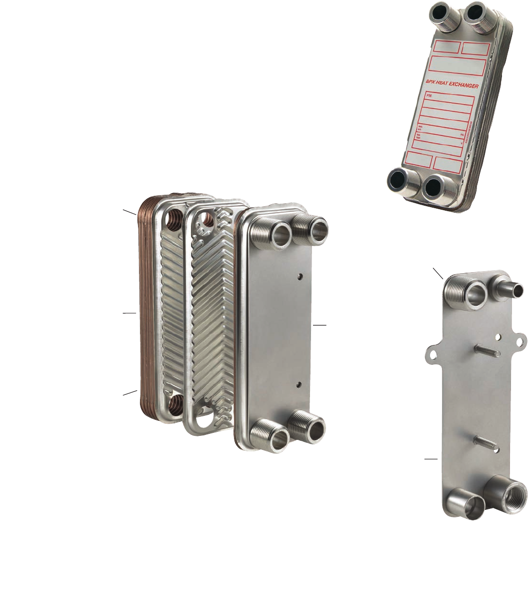
40
HEAT EXCHANGERS Brazed Plate Heat Exchangers
Description
Model BPX brazed plate heat exchangers offer the highest level
of thermal efficiency and durability in a compact, low cost unit.
The corrugated plate design provides very high heat transfer
coefficients, resulting in a more compact design. The unit’s
stainless steel plates are vacuum brazed together to form a
durable, integral piece that can withstand high pressure
and temperature.
The BPX heat exchangers offer a compact design compared to
shell and tube exchangers
• 1/6 the size of shell and tube
• 1/5 the weight of shell and tube
• 1/8 the liquid required of shell and tube
• 1/3 to 1/5 of the surface area required
BPX units are ideal for a wide variety
of hydronic applications such as:
• Radiant Floor Heating
• Domestic Water Heating
• Snow MELT Systems
• Swimming Pool Heating
Operating Data
Design Pressure: 435 PSI (30 bar)
Design Temperature: 450°F (232°C)
Plates: Stainless Steel
Braze Material: Copper
Connections: From 1/2 inch to 4 inch
Capacity: Up to 800 GPM
Construction Codes : UL, CRN, ASME Code
Stamp Option
Designed for dependability – Small size. Big impact.
Mechanical Design:
Design pressures up to 435 PSIG.
Maximum design temperature
up to 450˚F. Minimum design
temperature to -310˚F.
Capacity:
Up to 800 GPM and
350 sq.ft. of surface area.
Construction Codes:
Available codes include UL, CRN,
and ASME code stamp.
Materials:
Stainless steel 316L plates.
Copper brazed material.
Connections:
From 1/2-inch to 4-inch. Standard
connection options include NPT,
SAE flanged and sweat. Custom
connections available.
Mounting:
Reduce mounting costs with
optional threaded studs or
integral mounting bracket.
Also available in double-wall design.
41
HEAT EXCHANGERS Brazed Plate Heat Exchangers
Quick Selection Tables
Outdoor Wood Boiler
Boiler Side: Water 180º F supply, 155º F return
House Side: Water 140º F supply, 165º F return
Heat Boiler Side House Side
Model Exchanged Flow Pressure Drop Flow Pressure Drop
BTU/Hr GPM PSI GPM PSI
BP400-20LP (¾" MPT) 30,500 2.52 0.4 2.5 0.3
BP400-30LP (¾" MPT) 50,000 4.12 0.5 4.1 0.4
BP400-40LP (¾" MPT) 70,000 5.77 0.6 5.7 0.6
BP410-20LP (1" MPT) 80,000 6.60 1.9 6.5 1.6
BP410-30LP (1" MPT) 130,000 10.72 2.2 10.6 1.92
BP410-40LP (1" MPT) 179,500 14.80 2.3 14.6 2.2
BP410-50LP (1" MPT) 229,500 18.92 2.5 18.7 2.4
BP410-60LP (1" MPT) 279,000 23.00 2.8 22.8 2.6
BP410-70LP (1" MPT) 329,000 27.13 3.0 26.8 2.9
BP410-80LP (1" MPT) 378,500 31.21 3.3 30.9 3.2
BP410-90LP (1" MPT) 428,500 35.33 3.7 34.9 3.6
BP410-100LP (1" MPT) 478,000 39.41 4.0 39.0 4.0
Solar Heating
Solar Side: 45% Propylene Glycol 149° F supply, 113° F return
Storage Tank Side: Water 104° F supply, 140° F return
Heat Solar Side Storage Tank Side
Model Exchanged Flow Pressure Drop Flow Pressure Drop
BTU/Hr GPM PSI GPM PSI
BP410-10 (1" MPT) 2,100 0.13 < 0.10 0.12 < 0.10
BP410-20 (1" MPT) 6,100 0.38 < 0.10 0.34 < 0.10
BP410-30 (1" MPT) 10,100 0.62 < 0.10 0.57 < 0.10
BP410-40 (1" MPT) 14,100 0.87 < 0.10 0.79 < 0.10
BP415-20 (1" MPT) 24,500 1.51 0.24 1.38 0.13
BP415-24 (1" MPT) 30,800 1.90 0.25 1.73 0.15
BP415-30 (1" MPT) 40,100 2.47 0.27 2.25 0.16
BP415-34 (1" MPT) 46,500 2.86 0.28 2.61 0.17
BP415-40 (1" MPT) 56,100 3.45 0.29 3.15 0.18
BP415-50 (1" MPT) 72,000 4.43 0.30 4.04 0.20
BP415-60 (1" MPT) 87,900 5.41 0.32 4.94 0.21
Swimming Pool Heating
Boiler Side: Water 180º F supply, 130º F return
Pool Side: Water 70º F supply, 107º F return
Pool Heat Boiler Side Pool Side
Model
3
Size Exchanged Flow Pressure Drop Flow
2
Pressure Drop
Gallons
1
BTU/Hr GPM PSI GPM PSI
BP400-10 (¾" MPT) 2,000 33,300 1.37 0.5 1.8 0.6
BP400-10 (¾" MPT) 6,000 99,900 4.10 4.1 5.4 5.0
BP400-20 (¾" MPT) 8,000 133,200 5.50 1.7 7.3 2.5
BP400-30 (¾" MPT) 15,000 250,234 10.00 2.7 14.0 4.5
BP412-20 (1" MPT) 20,000 333,645 13.00 2.5 18.0 3.4
BP412-20 (1" MPT) 30,000 500,467 20.70 5.6 27.2 7.7
BP412-30 (1" MPT) 40,000 667,290 27.00 3.9 36.0 6.9
BP424-20 (2" MPT) 60,000 1,000,936 40.00 2.3 54.0 3.6
BP424-30 (2" MPT) 80,000 1,334,581 53.00 1.9 72.0 3.1
BP424-30 (2" MPT) 100,000 1,668,226 67.00 2.8 90.0 4.7
BP424-40 (2" MPT) 120,000 2,001,871 82.50 2.5 108.0 4.2
BP424-50 (2" MPT) 150,000 2,502,000 103.20 2.7 135.6 4.7
Larger models are available upon request.
1) Provides approx. 2º F per hour heating with 180º F boiler to achieve 80º F pool temperature.
2) Pool water flow rate usually requires flow by pass from main pool circulation.
3) Chlorinated pool water can be corrosive to SS316L and Copper. Proper control of chlorine levels is
required or alternate materials of construction should be considered.
Estimate how much heat you need:
Flow x Temperature Rise x 500 = Heat load
Example: (20 GPM) (20º F) (500) = 200,000 BTU/Hr
For a Radiant Heating Application, the choice would
be a BP400-40.
Quick Selection Tables
Radiant Floor Heating
Boiler Side: Water 180º F supply, 160º F return
Radiant Floor Side: Water 100º F supply, 120º F return
Heat Boiler Side Radiant Floor Side B&G Pipe
Model Exchanged Flow Pressure Drop Flow Pressure Drop Pump Size
††
BTU/Hr GPM PSI GPM PSI Selection
†
BP400-10 (¾" MPT) 30,000 3.1 2.4 3.0 1.6 NRF-25 ¾"
BP400-10 (¾" MPT) 50,000 5.2 6.1 5.0 4.2 NRF-36 1"
BP400-20 (¾" MPT) 100,000 10.3 5.2 10.1 4.4 NRF-36 1¼"
BP400-30 (¾" MPT) 150,000 15.5 5.3 15.2 4.9 NRF-36 1½"
BP400-40 (¾" MPT) 200,000 20.6 5.8 20.2 5.5 NRF-36 1½"
BP411-20 (1" MPT) 250,000 25.8 3.3 25.2 3.0 PL-36 2"
BP411-20 (1" MPT) 350,000 36.1 6.3 35.3 5.6 PL-55 2"
BP411-30 (1" MPT) 450,000 46.4 6.1 45.4 5.8 607 2"
BP424-20 (2" MPT) 600,000 61.8 4.8 60.6 4.2 609 2½"
BP424-30 (2" MPT) 900,000 92.7 4.8 90.9 4.5 611 3"
BP424-40 (2" MPT) 1,200,000 123.6 5.1 121.2 5.0 625 3"
BP424-50 (2" MPT) 1,350,000 139.1 4.7 136.3 4.6 619 3"
Larger models are available upon request.
† Assumptions: Longest radiant loop is 200 ft. PEX.
†† Pipe size shown isn’t the connection size of the heat exchanger.
Snow Melt Applications
Boiler Side: Water 180º F supply, 160º F return
Snow Side: Water 40% P. G. 100º F supply, 130º F return
Heat Boiler Side Snow Melt Side B&G Pipe
Model Exchanged Flow Pressure Drop Flow Pressure Drop Pump Size
††
BTU/Hr GPM PSI GPM PSI Selection
†
BP400-10 (¾" MPT) 30,000 3.1 2.4 2.1 0.9 NRF-25 ¾"
BP400-10 (¾" MPT) 45,000 4.6 5.1 3.2 2.1 NRF-35 ¾"
BP400-14 (¾" MPT) 60,000 6.2 4.2 4.3 1.9 NRF-25 1"
BP400-20 (¾" MPT) 100,000 10.3 5.4 7.1 2.7 NRF-36 1"
BP400-40 (¾" MPT) 175,000 18.0 5.2 12.5 2.8 NRF-36 1½"
BP412-30 (1" MPT) 250,000 25.8 4.1 17.9 2.1 PL-36 1½"
BP412-30 (1" MPT) 300,000 30.9 5.8 21.4 2.9 PL-55 2"
BP412-50 (1" MPT) 450,000 46.4 6.2 32.1 3.3 613 2"
BP424-20 (2" MPT) 600,000 61.8 4.8 42.9 2.8 609 2"
BP424-30 (2" MPT) 900,000 92.7 4.8 64.3 3.0 614 2½"
BP424-40 (2" MPT) 1,200,000 123.6 5.1 85.7 3.2 625 3"
BP424-50 (2" MPT) 1,350,000 139.1 4.7 96.4 2.9 625 3"
Larger models are available upon request.
† Assumptions: Longest radiant loop is 250 ft. PEX.
†† Pipe size shown isn't the connection size of the heat exchanger.
Domestic Water Heating
Boiler Side: Water 180º F supply, 130º F return
Domestic Water Side: Water 50º F supply, 140º F return
Heat Boiler Side Domestic Water Side B&G Pipe
Model Exchanged Flow Pressure Drop Flow Pressure Drop Pump Size
††
BTU/Hr GPM PSI GPM PSI Selection
†
BP400-10 (¾" MPT) 60,000 2.5 1.6 1.3 0.3 NBF-9U 5/8"
BP400-20 (¾" MPT) 150,000 6.2 2.1 3.3 0.6 NBF-9U ¾"
BP400-30 (¾" MPT) 225,000 9.3 2.2 5.0 0.7 NBF-9U 1"
BP400-40 (¾" MPT) 350,000 14.4 3.4 7.8 1.0 NBF-12 1¼"
BP410-30 (1" MPT) 450,000 18.6 6.2 10.0 1.8 NBF-25 1¼"
BP410-40 (1" MPT) 600,000 24.8 6.2 13.3 2.0 NBF-25 1½"
BP410-50 (1" MPT) 800,000 33.0 6.9 17.8 2.4 NBF-25 1½"
BP410-60 (1" MPT) 900,000 37.1 6.9 20.0 2.2 NBF-25 2"
BP410-80 (1" MPT) 1,100,000 45.4 6.8 24.4 2.2 NBF-36 2"
BP423-30 (2" MPT) 1,500,000 61.9 4.6 33.3 1.4 NBF-45 2"
BP423-40 (2" MPT) 2,000,000 82.5 4.6 44.4 1.4 PL-45B 2½"
BP423-50 (2" MPT) 2,500,000 103.1 4.8 55.5 1.5 PL-75B 2½"
Larger models are available upon request. † Assumptions: 200 ft. TEL of copper pipe with (6) 90 degree
elbows. †† Pipe size shown is not the connection size of the heat exchanger.
Larger models are available upon request.
Normal Panel Capacity = 190 BTU/Hr•Ft2
Larger models are available upon request.
Domestic Water Heating - Double Wall
Boiler Side: Water 180º F supply, 130º F return
Domestic Water Side: Water 50º F supply, 140º F return
Heat
Boiler Side Domestic Water Side
Model
Exchanged
Flow
Pressure Drop
Pressure Drop
BTU/Hr
GPM PSI GPM PSI
BPDW410-20 (1" MPT) 60,000 2.5 0.2 1.3 0.1 NBF-9U 5/8”
150,000 6.2 0.4 3.3 0.1 NBF-9U 3/4”
225,000 9.3 3.8 5.0 0.9 NBF-9U 1”
350,000 14.4 4.5 7.8 1.1 NBF-12 1-1/4”
450,000 18.6 5.4 10.0 1.4 NBF-25 1-1/4”
600,000 24.8 4.6 13.3 1.2 NBF-25 1-1/2”
800,000 33.0 5.1 17.8 1.4 NBF-25 1-1/2”
900,000 37.1 4.8 20.0 1.8 NBF-25 2”
1,100,000 45.4 6.3 24.4 3.1 NBF-36 2”
1,500,000
†††
61.9 4.5 33.3 1.3 NBF-45 2”
2,000,000
†††
82.5 5.9 44.4 1.7 NBF-45B 2-1/2”
† Assumptions: 20 ft. of copper pipe with (6) 90 degree elbows.
†† Pipe size shown isn't the connection size of the heat exchanger.
††† Two units are required in parallel.
BPDW410-34 (1" MPT)
BPDW415-24 (1" MPT)
BPDW415-34 (1" MPT)
BPDW415-40 (1" MPT)
BPDW415-60 (1" MPT)
BPDW415-80 (1" MPT)
BPDW415-100 (1" MPT)
BPDW415-110 (1" MPT)
(2)BPDW415-80 (1" MPT)
(2)BPDW415-100 (1" MPT)
B&G Pump
Selection
†
Pipe
Size
††
Flow
Outdoor Wood Boiler
Boiler Side: Water 180º F supply, 155º F return
House Side: Water 140º F supply, 165º F return
Heat Boiler Side House Side
Model Exchanged Flow Pressure Drop Flow Pressure Drop
BTU/Hr GPM PSI GPM PSI
BP400-20LP (¾" MPT) 30,500 2.52 0.4 2.5 0.3
BP400-30LP (¾" MPT) 50,000 4.12 0.5 4.1 0.4
BP400-40LP (¾" MPT) 70,000 5.77 0.6 5.7 0.6
BP410-20LP (1" MPT) 80,000 6.60 1.9 6.5 1.6
BP410-30LP (1" MPT) 130,000 10.72 2.2 10.6 1.92
BP410-40LP (1" MPT) 179,500 14.80 2.3 14.6 2.2
BP410-50LP (1" MPT) 229,500 18.92 2.5 18.7 2.4
BP410-60LP (1" MPT) 279,000 23.00 2.8 22.8 2.6
BP410-70LP (1" MPT) 329,000 27.13 3.0 26.8 2.9
BP410-80LP (1" MPT) 378,500 31.21 3.3 30.9 3.2
BP410-90LP (1" MPT) 428,500 35.33 3.7 34.9 3.6
BP410-100LP (1" MPT) 478,000 39.41 4.0 39.0 4.0
Solar Heating
Solar Side: 45% Propylene Glycol 149° F supply, 113° F return
Storage Tank Side: Water 104° F supply, 140° F return
Heat Solar Side Storage Tank Side
Model Exchanged Flow Pressure Drop Flow Pressure Drop
BTU/Hr GPM PSI GPM PSI
BP410-10 (1" MPT) 2,100 0.13 < 0.10 0.12 < 0.10
BP410-20 (1" MPT) 6,100 0.38 < 0.10 0.34 < 0.10
BP410-30 (1" MPT) 10,100 0.62 < 0.10 0.57 < 0.10
BP410-40 (1" MPT) 14,100 0.87 < 0.10 0.79 < 0.10
BP415-20 (1" MPT) 24,500 1.51 0.24 1.38 0.13
BP415-24 (1" MPT) 30,800 1.90 0.25 1.73 0.15
BP415-30 (1" MPT) 40,100 2.47 0.27 2.25 0.16
BP415-34 (1" MPT) 46,500 2.86 0.28 2.61 0.17
BP415-40 (1" MPT) 56,100 3.45 0.29 3.15 0.18
BP415-50 (1" MPT) 72,000 4.43 0.30 4.04 0.20
BP415-60 (1" MPT) 87,900 5.41 0.32 4.94 0.21
Swimming Pool Heating
Boiler Side: Water 180º F supply, 130º F return
Pool Side: Water 70º F supply, 107º F return
Pool Heat Boiler Side Pool Side
Model
3
Size Exchanged Flow Pressure Drop Flow
2
Pressure Drop
Gallons
1
BTU/Hr GPM PSI GPM PSI
BP400-10 (¾" MPT) 2,000 33,300 1.37 0.5 1.8 0.6
BP400-10 (¾" MPT) 6,000 99,900 4.10 4.1 5.4 5.0
BP400-20 (¾" MPT) 8,000 133,200 5.50 1.7 7.3 2.5
BP400-30 (¾" MPT) 15,000 250,234 10.00 2.7 14.0 4.5
BP412-20 (1" MPT) 20,000 333,645 13.00 2.5 18.0 3.4
BP412-20 (1" MPT) 30,000 500,467 20.70 5.6 27.2 7.7
BP412-30 (1" MPT) 40,000 667,290 27.00 3.9 36.0 6.9
BP424-20 (2" MPT) 60,000 1,000,936 40.00 2.3 54.0 3.6
BP424-30 (2" MPT) 80,000 1,334,581 53.00 1.9 72.0 3.1
BP424-30 (2" MPT) 100,000 1,668,226 67.00 2.8 90.0 4.7
BP424-40 (2" MPT) 120,000 2,001,871 82.50 2.5 108.0 4.2
BP424-50 (2" MPT) 150,000 2,502,000 103.20 2.7 135.6 4.7
Larger models are available upon request.
1) Provides approx. 2º F per hour heating with 180º F boiler to achieve 80º F pool temperature.
2) Pool water flow rate usually requires flow by pass from main pool circulation.
3) Chlorinated pool water can be corrosive to SS316L and Copper. Proper control of chlorine levels is
required or alternate materials of construction should be considered.
Estimate how much heat you need:
Flow x Temperature Rise x 500 = Heat load
Example: (20 GPM) (20º F) (500) = 200,000 BTU/Hr
For a Radiant Heating Application, the choice would
be a BP400-40.
Quick Selection Tables
Radiant Floor Heating
Boiler Side: Water 180º F supply, 160º F return
Radiant Floor Side: Water 100º F supply, 120º F return
Heat Boiler Side Radiant Floor Side B&G Pipe
Model Exchanged Flow Pressure Drop Flow Pressure Drop Pump Size
††
BTU/Hr GPM PSI GPM PSI Selection
†
BP400-10 (¾" MPT) 30,000 3.1 2.4 3.0 1.6 NRF-25 ¾"
BP400-10 (¾" MPT) 50,000 5.2 6.1 5.0 4.2 NRF-36 1"
BP400-20 (¾" MPT) 100,000 10.3 5.2 10.1 4.4 NRF-36 1¼"
BP400-30 (¾" MPT) 150,000 15.5 5.3 15.2 4.9 NRF-36 1½"
BP400-40 (¾" MPT) 200,000 20.6 5.8 20.2 5.5 NRF-36 1½"
BP411-20 (1" MPT) 250,000 25.8 3.3 25.2 3.0 PL-36 2"
BP411-20 (1" MPT) 350,000 36.1 6.3 35.3 5.6 PL-55 2"
BP411-30 (1" MPT) 450,000 46.4 6.1 45.4 5.8 607 2"
BP424-20 (2" MPT) 600,000 61.8 4.8 60.6 4.2 609 2½"
BP424-30 (2" MPT) 900,000 92.7 4.8 90.9 4.5 611 3"
BP424-40 (2" MPT) 1,200,000 123.6 5.1 121.2 5.0 625 3"
BP424-50 (2" MPT) 1,350,000 139.1 4.7 136.3 4.6 619 3"
Larger models are available upon request.
† Assumptions: Longest radiant loop is 200 ft. PEX.
†† Pipe size shown isn’t the connection size of the heat exchanger.
Snow Melt Applications
Boiler Side: Water 180º F supply, 160º F return
Snow Side: Water 40% P. G. 100º F supply, 130º F return
Heat Boiler Side Snow Melt Side B&G Pipe
Model Exchanged Flow Pressure Drop Flow Pressure Drop Pump Size
††
BTU/Hr GPM PSI GPM PSI Selection
†
BP400-10 (¾" MPT) 30,000 3.1 2.4 2.1 0.9 NRF-25 ¾"
BP400-10 (¾" MPT) 45,000 4.6 5.1 3.2 2.1 NRF-35 ¾"
BP400-14 (¾" MPT) 60,000 6.2 4.2 4.3 1.9 NRF-25 1"
BP400-20 (¾" MPT) 100,000 10.3 5.4 7.1 2.7 NRF-36 1"
BP400-40 (¾" MPT) 175,000 18.0 5.2 12.5 2.8 NRF-36 1½"
BP412-30 (1" MPT) 250,000 25.8 4.1 17.9 2.1 PL-36 1½"
BP412-30 (1" MPT) 300,000 30.9 5.8 21.4 2.9 PL-55 2"
BP412-50 (1" MPT) 450,000 46.4 6.2 32.1 3.3 613 2"
BP424-20 (2" MPT) 600,000 61.8 4.8 42.9 2.8 609 2"
BP424-30 (2" MPT) 900,000 92.7 4.8 64.3 3.0 614 2½"
BP424-40 (2" MPT) 1,200,000 123.6 5.1 85.7 3.2 625 3"
BP424-50 (2" MPT) 1,350,000 139.1 4.7 96.4 2.9 625 3"
Larger models are available upon request.
† Assumptions: Longest radiant loop is 250 ft. PEX.
†† Pipe size shown isn't the connection size of the heat exchanger.
Domestic Water Heating
Boiler Side: Water 180º F supply, 130º F return
Domestic Water Side: Water 50º F supply, 140º F return
Heat Boiler Side Domestic Water Side B&G Pipe
Model Exchanged Flow Pressure Drop Flow Pressure Drop Pump Size
††
BTU/Hr GPM PSI GPM PSI Selection
†
BP400-10 (¾" MPT) 60,000 2.5 1.6 1.3 0.3 NBF-9U
5
/
8
"
BP400-20 (¾" MPT) 150,000 6.2 2.1 3.3 0.6 NBF-9U ¾"
BP400-30 (¾" MPT) 225,000 9.3 2.2 5.0 0.7 NBF-9U 1"
BP400-40 (¾" MPT) 350,000 14.4 3.4 7.8 1.0 NBF-12 1¼"
BP410-30 (1" MPT) 450,000 18.6 6.2 10.0 1.8 NBF-25 1¼"
BP410-40 (1" MPT) 600,000 24.8 6.2 13.3 2.0 NBF-25 1½"
BP410-50 (1" MPT) 800,000 33.0 6.9 17.8 2.4 NBF-25 1½"
BP410-60 (1" MPT) 900,000 37.1 6.9 20.0 2.2 NBF-25 2"
BP410-80 (1" MPT) 1,100,000 45.4 6.8 24.4 2.2 NBF-36 2"
BP423-30 (2" MPT) 1,500,000 61.9 4.6 33.3 1.4 NBF-45 2"
BP423-40 (2" MPT) 2,000,000 82.5 4.6 44.4 1.4 PL-45B 2½"
BP423-50 (2" MPT) 2,500,000 103.1 4.8 55.5 1.5 PL-75B 2½"
Larger models are available upon request. † Assumptions: 200 ft. TEL of copper pipe with (6) 90 degree
elbows. †† Pipe size shown is not the connection size of the heat exchanger.
Larger models are available upon request.
Normal Panel Capacity = 190 BTU/Hr•Ft2
Larger models are available upon request.
Domestic Water Heating - Double Wall
Boiler Side: Water 180º F supply, 130º F return
Domestic Water Side: Water 50º F supply, 140º F return
Heat Boiler Side Domestic Water Side
Model
Exchanged Flow Pressure Drop Pressure Drop
BTU/Hr GPM PSI GPM PSI
BPDW410-20 (1" MPT) 60,000 2.5 0.2 1.3 0.1 NBF-9U 5/8”
150,000 6.2 0.4 3.3 0.1 NBF-9U 3/4”
225,000 9.3 3.8 5.0 0.9 NBF-9U 1”
350,000 14.4 4.5 7.8 1.1 NBF-12 1-1/4”
450,000 18.6 5.4 10.0 1.4 NBF-25 1-1/4”
600,000 24.8 4.6 13.3 1.2 NBF-25 1-1/2”
800,000 33.0 5.1 17.8 1.4 NBF-25 1-1/2”
900,000 37.1 4.8 20.0 1.8 NBF-25 2”
1,100,000 45.4 6.3 24.4 3.1 NBF-36 2”
1,500,000
†††
61.9 4.5 33.3 1.3 NBF-45 2”
2,000,000
†††
82.5 5.9 44.4 1.7 NBF-45B 2-1/2”
† Assumptions: 20 ft. of copper pipe with (6) 90 degree elbows.
†† Pipe size shown isn't the connection size of the heat exchanger.
††† Two units are required in parallel.
BPDW410-34 (1" MPT)
BPDW415-24 (1" MPT)
BPDW415-34 (1" MPT)
BPDW415-40 (1" MPT)
BPDW415-60 (1" MPT)
BPDW415-80 (1" MPT)
BPDW415-100 (1" MPT)
BPDW415-110 (1" MPT)
(2)BPDW415-80 (1" MPT)
(2)BPDW415-100 (1" MPT)
B&G Pump
Selection
†
Pipe
Size
††
Flow
Outdoor Wood Boiler
Boiler Side: Water 180º F supply, 155º F return
House Side: Water 140º F supply, 165º F return
Heat Boiler Side House Side
Model Exchanged Flow Pressure Drop Flow Pressure Drop
BTU/Hr GPM PSI GPM PSI
BP400-20LP (¾" MPT) 30,500 2.52 0.4 2.5 0.3
BP400-30LP (¾" MPT) 50,000 4.12 0.5 4.1 0.4
BP400-40LP (¾" MPT) 70,000 5.77 0.6 5.7 0.6
BP410-20LP (1" MPT) 80,000 6.60 1.9 6.5 1.6
BP410-30LP (1" MPT) 130,000 10.72 2.2 10.6 1.92
BP410-40LP (1" MPT) 179,500 14.80 2.3 14.6 2.2
BP410-50LP (1" MPT) 229,500 18.92 2.5 18.7 2.4
BP410-60LP (1" MPT) 279,000 23.00 2.8 22.8 2.6
BP410-70LP (1" MPT) 329,000 27.13 3.0 26.8 2.9
BP410-80LP (1" MPT) 378,500 31.21 3.3 30.9 3.2
BP410-90LP (1" MPT) 428,500 35.33 3.7 34.9 3.6
BP410-100LP (1" MPT) 478,000 39.41 4.0 39.0 4.0
Solar Heating
Solar Side: 45% Propylene Glycol 149° F supply, 113° F return
Storage Tank Side: Water 104° F supply, 140° F return
Heat Solar Side Storage Tank Side
Model Exchanged Flow Pressure Drop Flow Pressure Drop
BTU/Hr GPM PSI GPM PSI
BP410-10 (1" MPT) 2,100 0.13 < 0.10 0.12 < 0.10
BP410-20 (1" MPT) 6,100 0.38 < 0.10 0.34 < 0.10
BP410-30 (1" MPT) 10,100 0.62 < 0.10 0.57 < 0.10
BP410-40 (1" MPT) 14,100 0.87 < 0.10 0.79 < 0.10
BP415-20 (1" MPT) 24,500 1.51 0.24 1.38 0.13
BP415-24 (1" MPT) 30,800 1.90 0.25 1.73 0.15
BP415-30 (1" MPT) 40,100 2.47 0.27 2.25 0.16
BP415-34 (1" MPT) 46,500 2.86 0.28 2.61 0.17
BP415-40 (1" MPT) 56,100 3.45 0.29 3.15 0.18
BP415-50 (1" MPT) 72,000 4.43 0.30 4.04 0.20
BP415-60 (1" MPT) 87,900 5.41 0.32 4.94 0.21
Swimming Pool Heating
Boiler Side: Water 180º F supply, 130º F return
Pool Side: Water 70º F supply, 107º F return
Pool Heat Boiler Side Pool Side
Model
3
Size Exchanged Flow Pressure Drop Flow
2
Pressure Drop
Gallons
1
BTU/Hr GPM PSI GPM PSI
BP400-10 (¾" MPT) 2,000 33,300 1.37 0.5 1.8 0.6
BP400-10 (¾" MPT) 6,000 99,900 4.10 4.1 5.4 5.0
BP400-20 (¾" MPT) 8,000 133,200 5.50 1.7 7.3 2.5
BP400-30 (¾" MPT) 15,000 250,234 10.00 2.7 14.0 4.5
BP412-20 (1" MPT) 20,000 333,645 13.00 2.5 18.0 3.4
BP412-20 (1" MPT) 30,000 500,467 20.70 5.6 27.2 7.7
BP412-30 (1" MPT) 40,000 667,290 27.00 3.9 36.0 6.9
BP424-20 (2" MPT) 60,000 1,000,936 40.00 2.3 54.0 3.6
BP424-30 (2" MPT) 80,000 1,334,581 53.00 1.9 72.0 3.1
BP424-30 (2" MPT) 100,000 1,668,226 67.00 2.8 90.0 4.7
BP424-40 (2" MPT) 120,000 2,001,871 82.50 2.5 108.0 4.2
BP424-50 (2" MPT) 150,000 2,502,000 103.20 2.7 135.6 4.7
Larger models are available upon request.
1) Provides approx. 2º F per hour heating with 180º F boiler to achieve 80º F pool temperature.
2) Pool water flow rate usually requires flow by pass from main pool circulation.
3) Chlorinated pool water can be corrosive to SS316L and Copper. Proper control of chlorine levels is
required or alternate materials of construction should be considered.
Estimate how much heat you need:
Flow x Temperature Rise x 500 = Heat load
Example: (20 GPM) (20º F) (500) = 200,000 BTU/Hr
For a Radiant Heating Application, the choice would
be a BP400-40.
Quick Selection Tables
Radiant Floor Heating
Boiler Side: Water 180º F supply, 160º F return
Radiant Floor Side: Water 100º F supply, 120º F return
Heat Boiler Side Radiant Floor Side B&G Pipe
Model Exchanged Flow Pressure Drop Flow Pressure Drop Pump Size
††
BTU/Hr GPM PSI GPM PSI Selection
†
BP400-10 (¾" MPT) 30,000 3.1 2.4 3.0 1.6 NRF-25 ¾"
BP400-10 (¾" MPT) 50,000 5.2 6.1 5.0 4.2 NRF-36 1"
BP400-20 (¾" MPT) 100,000 10.3 5.2 10.1 4.4 NRF-36 1¼"
BP400-30 (¾" MPT) 150,000 15.5 5.3 15.2 4.9 NRF-36 1½"
BP400-40 (¾" MPT) 200,000 20.6 5.8 20.2 5.5 NRF-36 1½"
BP411-20 (1" MPT) 250,000 25.8 3.3 25.2 3.0 PL-36 2"
BP411-20 (1" MPT) 350,000 36.1 6.3 35.3 5.6 PL-55 2"
BP411-30 (1" MPT) 450,000 46.4 6.1 45.4 5.8 607 2"
BP424-20 (2" MPT) 600,000 61.8 4.8 60.6 4.2 609 2½"
BP424-30 (2" MPT) 900,000 92.7 4.8 90.9 4.5 611 3"
BP424-40 (2" MPT) 1,200,000 123.6 5.1 121.2 5.0 625 3"
BP424-50 (2" MPT) 1,350,000 139.1 4.7 136.3 4.6 619 3"
Larger models are available upon request.
† Assumptions: Longest radiant loop is 200 ft. PEX.
†† Pipe size shown isn’t the connection size of the heat exchanger.
Snow Melt Applications
Boiler Side: Water 180º F supply, 160º F return
Snow Side: Water 40% P. G. 100º F supply, 130º F return
Heat Boiler Side Snow Melt Side B&G Pipe
Model Exchanged Flow Pressure Drop Flow Pressure Drop Pump Size
††
BTU/Hr GPM PSI GPM PSI Selection
†
BP400-10 (¾" MPT) 30,000 3.1 2.4 2.1 0.9 NRF-25 ¾"
BP400-10 (¾" MPT) 45,000 4.6 5.1 3.2 2.1 NRF-35 ¾"
BP400-14 (¾" MPT) 60,000 6.2 4.2 4.3 1.9 NRF-25 1"
BP400-20 (¾" MPT) 100,000 10.3 5.4 7.1 2.7 NRF-36 1"
BP400-40 (¾" MPT) 175,000 18.0 5.2 12.5 2.8 NRF-36 1½"
BP412-30 (1" MPT) 250,000 25.8 4.1 17.9 2.1 PL-36 1½"
BP412-30 (1" MPT) 300,000 30.9 5.8 21.4 2.9 PL-55 2"
BP412-50 (1" MPT) 450,000 46.4 6.2 32.1 3.3 613 2"
BP424-20 (2" MPT) 600,000 61.8 4.8 42.9 2.8 609 2"
BP424-30 (2" MPT) 900,000 92.7 4.8 64.3 3.0 614 2½"
BP424-40 (2" MPT) 1,200,000 123.6 5.1 85.7 3.2 625 3"
BP424-50 (2" MPT) 1,350,000 139.1 4.7 96.4 2.9 625 3"
Larger models are available upon request.
† Assumptions: Longest radiant loop is 250 ft. PEX.
†† Pipe size shown isn't the connection size of the heat exchanger.
Domestic Water Heating
Boiler Side: Water 180º F supply, 130º F return
Domestic Water Side: Water 50º F supply, 140º F return
Heat Boiler Side Domestic Water Side B&G Pipe
Model Exchanged Flow Pressure Drop Flow Pressure Drop Pump Size
††
BTU/Hr GPM PSI GPM PSI Selection
†
BP400-10 (¾" MPT) 60,000 2.5 1.6 1.3 0.3 NBF-9U
5
/
8
"
BP400-20 (¾" MPT) 150,000 6.2 2.1 3.3 0.6 NBF-9U ¾"
BP400-30 (¾" MPT) 225,000 9.3 2.2 5.0 0.7 NBF-9U 1"
BP400-40 (¾" MPT) 350,000 14.4 3.4 7.8 1.0 NBF-12 1¼"
BP410-30 (1" MPT) 450,000 18.6 6.2 10.0 1.8 NBF-25 1¼"
BP410-40 (1" MPT) 600,000 24.8 6.2 13.3 2.0 NBF-25 1½"
BP410-50 (1" MPT) 800,000 33.0 6.9 17.8 2.4 NBF-25 1½"
BP410-60 (1" MPT) 900,000 37.1 6.9 20.0 2.2 NBF-25 2"
BP410-80 (1" MPT) 1,100,000 45.4 6.8 24.4 2.2 NBF-36 2"
BP423-30 (2" MPT) 1,500,000 61.9 4.6 33.3 1.4 NBF-45 2"
BP423-40 (2" MPT) 2,000,000 82.5 4.6 44.4 1.4 PL-45B 2½"
BP423-50 (2" MPT) 2,500,000 103.1 4.8 55.5 1.5 PL-75B 2½"
Larger models are available upon request. † Assumptions: 200 ft. TEL of copper pipe with (6) 90 degree
elbows. †† Pipe size shown is not the connection size of the heat exchanger.
Larger models are available upon request.
Normal Panel Capacity = 190 BTU/Hr•Ft2
Larger models are available upon request.
Domestic Water Heating - Double Wall
Boiler Side: Water 180º F supply, 130º F return
Domestic Water Side: Water 50º F supply, 140º F return
Heat
Boiler Side Domestic Water Side
Model
Exchanged
Flow
Pressure Drop
Pressure Drop
BTU/Hr
GPM PSI GPM PSI
BPDW410-20 (1" MPT) 60,000 2.5 0.2 1.3 0.1 NBF-9U 5/8”
150,000 6.2 0.4 3.3 0.1 NBF-9U 3/4”
225,000 9.3 3.8 5.0 0.9 NBF-9U 1”
350,000 14.4 4.5 7.8 1.1 NBF-12 1-1/4”
450,000 18.6 5.4 10.0 1.4 NBF-25 1-1/4”
600,000 24.8 4.6 13.3 1.2 NBF-25 1-1/2”
800,000 33.0 5.1 17.8 1.4 NBF-25 1-1/2”
900,000 37.1 4.8 20.0 1.8 NBF-25 2”
1,100,000 45.4 6.3 24.4 3.1 NBF-36 2”
1,500,000
†††
61.9 4.5 33.3 1.3 NBF-45 2”
2,000,000
†††
82.5 5.9 44.4 1.7 NBF-45B 2-1/2”
† Assumptions: 20 ft. of copper pipe with (6) 90 degree elbows.
†† Pipe size shown isn't the connection size of the heat exchanger.
††† Two units are required in parallel.
BPDW410-34 (1" MPT)
BPDW415-24 (1" MPT)
BPDW415-34 (1" MPT)
BPDW415-40 (1" MPT)
BPDW415-60 (1" MPT)
BPDW415-80 (1" MPT)
BPDW415-100 (1" MPT)
BPDW415-110 (1" MPT)
(2)BPDW415-80 (1" MPT)
(2)BPDW415-100 (1" MPT)
B&G Pump
Selection
†
Pipe
Size
††
Flow
Outdoor Wood Boiler
Boiler Side: Water 180º F supply, 155º F return
House Side: Water 140º F supply, 165º F return
Heat Boiler Side House Side
Model Exchanged Flow Pressure Drop Flow Pressure Drop
BTU/Hr GPM PSI GPM PSI
BP400-20LP (¾" MPT) 30,500 2.52 0.4 2.5 0.3
BP400-30LP (¾" MPT) 50,000 4.12 0.5 4.1 0.4
BP400-40LP (¾" MPT) 70,000 5.77 0.6 5.7 0.6
BP410-20LP (1" MPT) 80,000 6.60 1.9 6.5 1.6
BP410-30LP (1" MPT) 130,000 10.72 2.2 10.6 1.92
BP410-40LP (1" MPT) 179,500 14.80 2.3 14.6 2.2
BP410-50LP (1" MPT) 229,500 18.92 2.5 18.7 2.4
BP410-60LP (1" MPT) 279,000 23.00 2.8 22.8 2.6
BP410-70LP (1" MPT) 329,000 27.13 3.0 26.8 2.9
BP410-80LP (1" MPT) 378,500 31.21 3.3 30.9 3.2
BP410-90LP (1" MPT) 428,500 35.33 3.7 34.9 3.6
BP410-100LP (1" MPT) 478,000 39.41 4.0 39.0 4.0
Solar Heating
Solar Side: 45% Propylene Glycol 149° F supply, 113° F return
Storage Tank Side: Water 104° F supply, 140° F return
Heat Solar Side Storage Tank Side
Model Exchanged Flow Pressure Drop Flow Pressure Drop
BTU/Hr GPM PSI GPM PSI
BP410-10 (1" MPT) 2,100 0.13 < 0.10 0.12 < 0.10
BP410-20 (1" MPT) 6,100 0.38 < 0.10 0.34 < 0.10
BP410-30 (1" MPT) 10,100 0.62 < 0.10 0.57 < 0.10
BP410-40 (1" MPT) 14,100 0.87 < 0.10 0.79 < 0.10
BP415-20 (1" MPT) 24,500 1.51 0.24 1.38 0.13
BP415-24 (1" MPT) 30,800 1.90 0.25 1.73 0.15
BP415-30 (1" MPT) 40,100 2.47 0.27 2.25 0.16
BP415-34 (1" MPT) 46,500 2.86 0.28 2.61 0.17
BP415-40 (1" MPT) 56,100 3.45 0.29 3.15 0.18
BP415-50 (1" MPT) 72,000 4.43 0.30 4.04 0.20
BP415-60 (1" MPT) 87,900 5.41 0.32 4.94 0.21
Swimming Pool Heating
Boiler Side: Water 180º F supply, 130º F return
Pool Side: Water 70º F supply, 107º F return
Pool Heat Boiler Side Pool Side
Model
3
Size Exchanged Flow Pressure Drop Flow
2
Pressure Drop
Gallons
1
BTU/Hr GPM PSI GPM PSI
BP400-10 (¾" MPT) 2,000 33,300 1.37 0.5 1.8 0.6
BP400-10 (¾" MPT) 6,000 99,900 4.10 4.1 5.4 5.0
BP400-20 (¾" MPT) 8,000 133,200 5.50 1.7 7.3 2.5
BP400-30 (¾" MPT) 15,000 250,234 10.00 2.7 14.0 4.5
BP412-20 (1" MPT) 20,000 333,645 13.00 2.5 18.0 3.4
BP412-20 (1" MPT) 30,000 500,467 20.70 5.6 27.2 7.7
BP412-30 (1" MPT) 40,000 667,290 27.00 3.9 36.0 6.9
BP424-20 (2" MPT) 60,000 1,000,936 40.00 2.3 54.0 3.6
BP424-30 (2" MPT) 80,000 1,334,581 53.00 1.9 72.0 3.1
BP424-30 (2" MPT) 100,000 1,668,226 67.00 2.8 90.0 4.7
BP424-40 (2" MPT) 120,000 2,001,871 82.50 2.5 108.0 4.2
BP424-50 (2" MPT) 150,000 2,502,000 103.20 2.7 135.6 4.7
Larger models are available upon request.
1) Provides approx. 2º F per hour heating with 180º F boiler to achieve 80º F pool temperature.
2) Pool water flow rate usually requires flow by pass from main pool circulation.
3) Chlorinated pool water can be corrosive to SS316L and Copper. Proper control of chlorine levels is
required or alternate materials of construction should be considered.
Estimate how much heat you need:
Flow x Temperature Rise x 500 = Heat load
Example: (20 GPM) (20º F) (500) = 200,000 BTU/Hr
For a Radiant Heating Application, the choice would
be a BP400-40.
Quick Selection Tables
Radiant Floor Heating
Boiler Side: Water 180º F supply, 160º F return
Radiant Floor Side: Water 100º F supply, 120º F return
Heat Boiler Side Radiant Floor Side B&G Pipe
Model Exchanged Flow Pressure Drop Flow Pressure Drop Pump Size
††
BTU/Hr GPM PSI GPM PSI Selection
†
BP400-10 (¾" MPT) 30,000 3.1 2.4 3.0 1.6 NRF-25 ¾"
BP400-10 (¾" MPT) 50,000 5.2 6.1 5.0 4.2 NRF-36 1"
BP400-20 (¾" MPT) 100,000 10.3 5.2 10.1 4.4 NRF-36 1¼"
BP400-30 (¾" MPT) 150,000 15.5 5.3 15.2 4.9 NRF-36 1½"
BP400-40 (¾" MPT) 200,000 20.6 5.8 20.2 5.5 NRF-36 1½"
BP411-20 (1" MPT) 250,000 25.8 3.3 25.2 3.0 PL-36 2"
BP411-20 (1" MPT) 350,000 36.1 6.3 35.3 5.6 PL-55 2"
BP411-30 (1" MPT) 450,000 46.4 6.1 45.4 5.8 607 2"
BP424-20 (2" MPT) 600,000 61.8 4.8 60.6 4.2 609 2½"
BP424-30 (2" MPT) 900,000 92.7 4.8 90.9 4.5 611 3"
BP424-40 (2" MPT) 1,200,000 123.6 5.1 121.2 5.0 625 3"
BP424-50 (2" MPT) 1,350,000 139.1 4.7 136.3 4.6 619 3"
Larger models are available upon request.
† Assumptions: Longest radiant loop is 200 ft. PEX.
†† Pipe size shown isn’t the connection size of the heat exchanger.
Snow Melt Applications
Boiler Side: Water 180º F supply, 160º F return
Snow Side: Water 40% P. G. 100º F supply, 130º F return
Heat Boiler Side Snow Melt Side B&G Pipe
Model Exchanged Flow Pressure Drop Flow Pressure Drop Pump Size
††
BTU/Hr GPM PSI GPM PSI Selection
†
BP400-10 (¾" MPT) 30,000 3.1 2.4 2.1 0.9 NRF-25 ¾"
BP400-10 (¾" MPT) 45,000 4.6 5.1 3.2 2.1 NRF-35 ¾"
BP400-14 (¾" MPT) 60,000 6.2 4.2 4.3 1.9 NRF-25 1"
BP400-20 (¾" MPT) 100,000 10.3 5.4 7.1 2.7 NRF-36 1"
BP400-40 (¾" MPT) 175,000 18.0 5.2 12.5 2.8 NRF-36 1½"
BP412-30 (1" MPT) 250,000 25.8 4.1 17.9 2.1 PL-36 1½"
BP412-30 (1" MPT) 300,000 30.9 5.8 21.4 2.9 PL-55 2"
BP412-50 (1" MPT) 450,000 46.4 6.2 32.1 3.3 613 2"
BP424-20 (2" MPT) 600,000 61.8 4.8 42.9 2.8 609 2"
BP424-30 (2" MPT) 900,000 92.7 4.8 64.3 3.0 614 2½"
BP424-40 (2" MPT) 1,200,000 123.6 5.1 85.7 3.2 625 3"
BP424-50 (2" MPT) 1,350,000 139.1 4.7 96.4 2.9 625 3"
Larger models are available upon request.
† Assumptions: Longest radiant loop is 250 ft. PEX.
†† Pipe size shown isn't the connection size of the heat exchanger.
Domestic Water Heating
Boiler Side: Water 180º F supply, 130º F return
Domestic Water Side: Water 50º F supply, 140º F return
Heat Boiler Side Domestic Water Side B&G Pipe
Model Exchanged Flow Pressure Drop Flow Pressure Drop Pump Size
††
BTU/Hr GPM PSI GPM PSI Selection
†
BP400-10 (¾" MPT) 60,000 2.5 1.6 1.3 0.3 NBF-9U
5
/
8
"
BP400-20 (¾" MPT) 150,000 6.2 2.1 3.3 0.6 NBF-9U ¾"
BP400-30 (¾" MPT) 225,000 9.3 2.2 5.0 0.7 NBF-9U 1"
BP400-40 (¾" MPT) 350,000 14.4 3.4 7.8 1.0 NBF-12 1¼"
BP410-30 (1" MPT) 450,000 18.6 6.2 10.0 1.8 NBF-25 1¼"
BP410-40 (1" MPT) 600,000 24.8 6.2 13.3 2.0 NBF-25 1½"
BP410-50 (1" MPT) 800,000 33.0 6.9 17.8 2.4 NBF-25 1½"
BP410-60 (1" MPT) 900,000 37.1 6.9 20.0 2.2 NBF-25 2"
BP410-80 (1" MPT) 1,100,000 45.4 6.8 24.4 2.2 NBF-36 2"
BP423-30 (2" MPT) 1,500,000 61.9 4.6 33.3 1.4 NBF-45 2"
BP423-40 (2" MPT) 2,000,000 82.5 4.6 44.4 1.4 PL-45B 2½"
BP423-50 (2" MPT) 2,500,000 103.1 4.8 55.5 1.5 PL-75B 2½"
Larger models are available upon request. † Assumptions: 200 ft. TEL of copper pipe with (6) 90 degree
elbows. †† Pipe size shown is not the connection size of the heat exchanger.
Larger models are available upon request.
Normal Panel Capacity = 190 BTU/Hr•Ft2
Larger models are available upon request.
Domestic Water Heating - Double Wall
Boiler Side: Water 180º F supply, 130º F return
Domestic Water Side: Water 50º F supply, 140º F return
Heat Boiler Side Domestic Water Side
Model
Exchanged Flow Pressure Drop Pressure Drop
BTU/Hr GPM PSI GPM PSI
BPDW410-20 (1" MPT) 60,000 2.5 0.2 1.3 0.1 NBF-9U 5/8”
150,000 6.2 0.4 3.3 0.1 NBF-9U 3/4”
225,000 9.3 3.8 5.0 0.9 NBF-9U 1”
350,000 14.4 4.5 7.8 1.1 NBF-12 1-1/4”
450,000 18.6 5.4 10.0 1.4 NBF-25 1-1/4”
600,000 24.8 4.6 13.3 1.2 NBF-25 1-1/2”
800,000 33.0 5.1 17.8 1.4 NBF-25 1-1/2”
900,000 37.1 4.8 20.0 1.8 NBF-25 2”
1,100,000 45.4 6.3 24.4 3.1 NBF-36 2”
1,500,000
†††
61.9 4.5 33.3 1.3 NBF-45 2”
2,000,000
†††
82.5 5.9 44.4 1.7 NBF-45B 2-1/2”
† Assumptions: 20 ft. of copper pipe with (6) 90 degree elbows.
†† Pipe size shown isn't the connection size of the heat exchanger.
††† Two units are required in parallel.
BPDW410-34 (1" MPT)
BPDW415-24 (1" MPT)
BPDW415-34 (1" MPT)
BPDW415-40 (1" MPT)
BPDW415-60 (1" MPT)
BPDW415-80 (1" MPT)
BPDW415-100 (1" MPT)
BPDW415-110 (1" MPT)
(2)BPDW415-80 (1" MPT)
(2)BPDW415-100 (1" MPT)
B&G Pump
Selection
†
Pipe
Size
††
Flow
Outdoor Wood Boiler
Boiler Side: Water 180º F supply, 155º F return
House Side: Water 140º F supply, 165º F return
Heat Boiler Side House Side
Model Exchanged Flow Pressure Drop Flow Pressure Drop
BTU/Hr GPM PSI GPM PSI
BP400-20LP (¾" MPT) 30,500 2.52 0.4 2.5 0.3
BP400-30LP (¾" MPT) 50,000 4.12 0.5 4.1 0.4
BP400-40LP (¾" MPT) 70,000 5.77 0.6 5.7 0.6
BP410-20LP (1" MPT) 80,000 6.60 1.9 6.5 1.6
BP410-30LP (1" MPT) 130,000 10.72 2.2 10.6 1.92
BP410-40LP (1" MPT) 179,500 14.80 2.3 14.6 2.2
BP410-50LP (1" MPT) 229,500 18.92 2.5 18.7 2.4
BP410-60LP (1" MPT) 279,000 23.00 2.8 22.8 2.6
BP410-70LP (1" MPT) 329,000 27.13 3.0 26.8 2.9
BP410-80LP (1" MPT) 378,500 31.21 3.3 30.9 3.2
BP410-90LP (1" MPT) 428,500 35.33 3.7 34.9 3.6
BP410-100LP (1" MPT) 478,000 39.41 4.0 39.0 4.0
Solar Heating
Solar Side: 45% Propylene Glycol 149° F supply, 113° F return
Storage Tank Side: Water 104° F supply, 140° F return
Heat Solar Side Storage Tank Side
Model Exchanged Flow Pressure Drop Flow Pressure Drop
BTU/Hr GPM PSI GPM PSI
BP410-10 (1" MPT) 2,100 0.13 < 0.10 0.12 < 0.10
BP410-20 (1" MPT) 6,100 0.38 < 0.10 0.34 < 0.10
BP410-30 (1" MPT) 10,100 0.62 < 0.10 0.57 < 0.10
BP410-40 (1" MPT) 14,100 0.87 < 0.10 0.79 < 0.10
BP415-20 (1" MPT) 24,500 1.51 0.24 1.38 0.13
BP415-24 (1" MPT) 30,800 1.90 0.25 1.73 0.15
BP415-30 (1" MPT) 40,100 2.47 0.27 2.25 0.16
BP415-34 (1" MPT) 46,500 2.86 0.28 2.61 0.17
BP415-40 (1" MPT) 56,100 3.45 0.29 3.15 0.18
BP415-50 (1" MPT) 72,000 4.43 0.30 4.04 0.20
BP415-60 (1" MPT) 87,900 5.41 0.32 4.94 0.21
Swimming Pool Heating
Boiler Side: Water 180º F supply, 130º F return
Pool Side: Water 70º F supply, 107º F return
Pool Heat Boiler Side Pool Side
Model3 Size Exchanged Flow Pressure Drop Flow2 Pressure Drop
Gallons1 BTU/Hr GPM PSI GPM PSI
BP400-10 (¾" MPT) 2,000 33,300 1.37 0.5 1.8 0.6
BP400-10 (¾" MPT) 6,000 99,900 4.10 4.1 5.4 5.0
BP400-20 (¾" MPT) 8,000 133,200 5.50 1.7 7.3 2.5
BP400-30 (¾" MPT) 15,000 250,234 10.00 2.7 14.0 4.5
BP412-20 (1" MPT) 20,000 333,645 13.00 2.5 18.0 3.4
BP412-20 (1" MPT) 30,000 500,467 20.70 5.6 27.2 7.7
BP412-30 (1" MPT) 40,000 667,290 27.00 3.9 36.0 6.9
BP424-20 (2" MPT) 60,000 1,000,936 40.00 2.3 54.0 3.6
BP424-30 (2" MPT) 80,000 1,334,581 53.00 1.9 72.0 3.1
BP424-30 (2" MPT) 100,000 1,668,226 67.00 2.8 90.0 4.7
BP424-40 (2" MPT) 120,000 2,001,871 82.50 2.5 108.0 4.2
BP424-50 (2" MPT) 150,000 2,502,000 103.20 2.7 135.6 4.7
Larger models are available upon request.
1) Provides approx. 2º F per hour heating with 180º F boiler to achieve 80º F pool temperature.
2) Pool water flow rate usually requires flow by pass from main pool circulation.
3) Chlorinated pool water can be corrosive to SS316L and Copper. Proper control of chlorine levels is
required or alternate materials of construction should be considered.
Estimate how much heat you need:
Flow x Temperature Rise x 500 = Heat load
Example: (20 GPM) (20º F) (500) = 200,000 BTU/Hr
For a Radiant Heating Application, the choice would
be a BP400-40.
Quick Selection Tables
Radiant Floor Heating
Boiler Side: Water 180º F supply, 160º F return
Radiant Floor Side: Water 100º F supply, 120º F return
Heat Boiler Side Radiant Floor Side B&G Pipe
Model Exchanged Flow Pressure Drop Flow Pressure Drop Pump Size††
BTU/Hr GPM PSI GPM PSI Selection†
BP400-10 (¾" MPT) 30,000 3.1 2.4 3.0 1.6 NRF-25 ¾"
BP400-10 (¾" MPT) 50,000 5.2 6.1 5.0 4.2 NRF-36 1"
BP400-20 (¾" MPT) 100,000 10.3 5.2 10.1 4.4 NRF-36 1¼"
BP400-30 (¾" MPT) 150,000 15.5 5.3 15.2 4.9 NRF-36 1½"
BP400-40 (¾" MPT) 200,000 20.6 5.8 20.2 5.5 NRF-36 1½"
BP411-20 (1" MPT) 250,000 25.8 3.3 25.2 3.0 PL-36 2"
BP411-20 (1" MPT) 350,000 36.1 6.3 35.3 5.6 PL-55 2"
BP411-30 (1" MPT) 450,000 46.4 6.1 45.4 5.8 607 2"
BP424-20 (2" MPT) 600,000 61.8 4.8 60.6 4.2 609 2½"
BP424-30 (2" MPT) 900,000 92.7 4.8 90.9 4.5 611 3"
BP424-40 (2" MPT) 1,200,000 123.6 5.1 121.2 5.0 625 3"
BP424-50 (2" MPT) 1,350,000 139.1 4.7 136.3 4.6 619 3"
Larger models are available upon request.
† Assumptions: Longest radiant loop is 200 ft. PEX.
†† Pipe size shown isn’t the connection size of the heat exchanger.
Snow Melt Applications
Boiler Side: Water 180º F supply, 160º F return
Snow Side: Water 40% P. G. 100º F supply, 130º F return
Heat Boiler Side Snow Melt Side B&G Pipe
Model Exchanged Flow Pressure Drop Flow Pressure Drop Pump Size††
BTU/Hr GPM PSI GPM PSI Selection†
BP400-10 (¾" MPT) 30,000 3.1 2.4 2.1 0.9 NRF-25 ¾"
BP400-10 (¾" MPT) 45,000 4.6 5.1 3.2 2.1 NRF-35 ¾"
BP400-14 (¾" MPT) 60,000 6.2 4.2 4.3 1.9 NRF-25 1"
BP400-20 (¾" MPT) 100,000 10.3 5.4 7.1 2.7 NRF-36 1"
BP400-40 (¾" MPT) 175,000 18.0 5.2 12.5 2.8 NRF-36 1½"
BP412-30 (1" MPT) 250,000 25.8 4.1 17.9 2.1 PL-36 1½"
BP412-30 (1" MPT) 300,000 30.9 5.8 21.4 2.9 PL-55 2"
BP412-50 (1" MPT) 450,000 46.4 6.2 32.1 3.3 613 2"
BP424-20 (2" MPT) 600,000 61.8 4.8 42.9 2.8 609 2"
BP424-30 (2" MPT) 900,000 92.7 4.8 64.3 3.0 614 2½"
BP424-40 (2" MPT) 1,200,000 123.6 5.1 85.7 3.2 625 3"
BP424-50 (2" MPT) 1,350,000 139.1 4.7 96.4 2.9 625 3"
Larger models are available upon request.
† Assumptions: Longest radiant loop is 250 ft. PEX.
†† Pipe size shown isn't the connection size of the heat exchanger.
Domestic Water Heating
Boiler Side: Water 180º F supply, 130º F return
Domestic Water Side: Water 50º F supply, 140º F return
Heat Boiler Side Domestic Water Side B&G Pipe
Model Exchanged Flow Pressure Drop Flow Pressure Drop Pump Size††
BTU/Hr GPM PSI GPM PSI Selection†
BP400-10 (¾" MPT) 60,000 2.5 1.6 1.3 0.3 NBF-9U
5
/
8
"
BP400-20 (¾" MPT) 150,000 6.2 2.1 3.3 0.6 NBF-9U ¾"
BP400-30 (¾" MPT) 225,000 9.3 2.2 5.0 0.7 NBF-9U 1"
BP400-40 (¾" MPT) 350,000 14.4 3.4 7.8 1.0 NBF-12 1¼"
BP410-30 (1" MPT) 450,000 18.6 6.2 10.0 1.8 NBF-25 1¼"
BP410-40 (1" MPT) 600,000 24.8 6.2 13.3 2.0 NBF-25 1½"
BP410-50 (1" MPT) 800,000 33.0 6.9 17.8 2.4 NBF-25 1½"
BP410-60 (1" MPT) 900,000 37.1 6.9 20.0 2.2 NBF-25 2"
BP410-80 (1" MPT) 1,100,000 45.4 6.8 24.4 2.2 NBF-36 2"
BP423-30 (2" MPT) 1,500,000 61.9 4.6 33.3 1.4 NBF-45 2"
BP423-40 (2" MPT) 2,000,000 82.5 4.6 44.4 1.4 PL-45B 2½"
BP423-50 (2" MPT) 2,500,000 103.1 4.8 55.5 1.5 PL-75B 2½"
Larger models are available upon request. † Assumptions: 200 ft. TEL of copper pipe with (6) 90 degree
elbows. †† Pipe size shown is not the connection size of the heat exchanger.
Larger models are available upon request.
Normal Panel Capacity = 190 BTU/Hr•Ft2
Larger models are available upon request.
Domestic Water Heating - Double Wall
Boiler Side: Water 180º F supply, 130º F return
Domestic Water Side: Water 50º F supply, 140º F return
Heat
Boiler Side Domestic Water Side
Model
Exchanged
Flow
Pressure Drop
Pressure Drop
BTU/Hr
GPM PSI GPM PSI
BPDW410-20 (1" MPT) 60,000 2.5 0.2 1.3 0.1 NBF-9U 5/8”
150,000 6.2 0.4 3.3 0.1 NBF-9U 3/4”
225,000 9.3 3.8 5.0 0.9 NBF-9U 1”
350,000 14.4 4.5 7.8 1.1 NBF-12 1-1/4”
450,000 18.6 5.4 10.0 1.4 NBF-25 1-1/4”
600,000 24.8 4.6 13.3 1.2 NBF-25 1-1/2”
800,000 33.0 5.1 17.8 1.4 NBF-25 1-1/2”
900,000 37.1 4.8 20.0 1.8 NBF-25 2”
1,100,000 45.4 6.3 24.4 3.1 NBF-36 2”
1,500,000
†††
61.9 4.5 33.3 1.3 NBF-45 2”
2,000,000
†††
82.5 5.9 44.4 1.7 NBF-45B 2-1/2”
† Assumptions: 20 ft. of copper pipe with (6) 90 degree elbows.
†† Pipe size shown isn't the connection size of the heat exchanger.
††† Two units are required in parallel.
BPDW410-34 (1" MPT)
BPDW415-24 (1" MPT)
BPDW415-34 (1" MPT)
BPDW415-40 (1" MPT)
BPDW415-60 (1" MPT)
BPDW415-80 (1" MPT)
BPDW415-100 (1" MPT)
BPDW415-110 (1" MPT)
(2)BPDW415-80 (1" MPT)
(2)BPDW415-100 (1" MPT)
B&G Pump
Selection
†
Pipe
Size
††
Flow
Outdoor Wood Boiler
Boiler Side: Water 180º F supply, 155º F return
House Side: Water 140º F supply, 165º F return
Heat Boiler Side House Side
Model Exchanged Flow Pressure Drop Flow Pressure Drop
BTU/Hr GPM PSI GPM PSI
BP400-20LP (¾" MPT) 30,500 2.52 0.4 2.5 0.3
BP400-30LP (¾" MPT) 50,000 4.12 0.5 4.1 0.4
BP400-40LP (¾" MPT) 70,000 5.77 0.6 5.7 0.6
BP410-20LP (1" MPT) 80,000 6.60 1.9 6.5 1.6
BP410-30LP (1" MPT) 130,000 10.72 2.2 10.6 1.92
BP410-40LP (1" MPT) 179,500 14.80 2.3 14.6 2.2
BP410-50LP (1" MPT) 229,500 18.92 2.5 18.7 2.4
BP410-60LP (1" MPT) 279,000 23.00 2.8 22.8 2.6
BP410-70LP (1" MPT) 329,000 27.13 3.0 26.8 2.9
BP410-80LP (1" MPT) 378,500 31.21 3.3 30.9 3.2
BP410-90LP (1" MPT) 428,500 35.33 3.7 34.9 3.6
BP410-100LP (1" MPT) 478,000 39.41 4.0 39.0 4.0
Solar Heating
Solar Side: 45% Propylene Glycol 149° F supply, 113° F return
Storage Tank Side: Water 104° F supply, 140° F return
Heat Solar Side Storage Tank Side
Model Exchanged Flow Pressure Drop Flow Pressure Drop
BTU/Hr GPM PSI GPM PSI
BP410-10 (1" MPT) 2,100 0.13 < 0.10 0.12 < 0.10
BP410-20 (1" MPT) 6,100 0.38 < 0.10 0.34 < 0.10
BP410-30 (1" MPT) 10,100 0.62 < 0.10 0.57 < 0.10
BP410-40 (1" MPT) 14,100 0.87 < 0.10 0.79 < 0.10
BP415-20 (1" MPT) 24,500 1.51 0.24 1.38 0.13
BP415-24 (1" MPT) 30,800 1.90 0.25 1.73 0.15
BP415-30 (1" MPT) 40,100 2.47 0.27 2.25 0.16
BP415-34 (1" MPT) 46,500 2.86 0.28 2.61 0.17
BP415-40 (1" MPT) 56,100 3.45 0.29 3.15 0.18
BP415-50 (1" MPT) 72,000 4.43 0.30 4.04 0.20
BP415-60 (1" MPT) 87,900 5.41 0.32 4.94 0.21
Swimming Pool Heating
Boiler Side: Water 180º F supply, 130º F return
Pool Side: Water 70º F supply, 107º F return
Pool Heat Boiler Side Pool Side
Model
3
Size Exchanged Flow Pressure Drop Flow
2
Pressure Drop
Gallons
1
BTU/Hr GPM PSI GPM PSI
BP400-10 (¾" MPT) 2,000 33,300 1.37 0.5 1.8 0.6
BP400-10 (¾" MPT) 6,000 99,900 4.10 4.1 5.4 5.0
BP400-20 (¾" MPT) 8,000 133,200 5.50 1.7 7.3 2.5
BP400-30 (¾" MPT) 15,000 250,234 10.00 2.7 14.0 4.5
BP412-20 (1" MPT) 20,000 333,645 13.00 2.5 18.0 3.4
BP412-20 (1" MPT) 30,000 500,467 20.70 5.6 27.2 7.7
BP412-30 (1" MPT) 40,000 667,290 27.00 3.9 36.0 6.9
BP424-20 (2" MPT) 60,000 1,000,936 40.00 2.3 54.0 3.6
BP424-30 (2" MPT) 80,000 1,334,581 53.00 1.9 72.0 3.1
BP424-30 (2" MPT) 100,000 1,668,226 67.00 2.8 90.0 4.7
BP424-40 (2" MPT) 120,000 2,001,871 82.50 2.5 108.0 4.2
BP424-50 (2" MPT) 150,000 2,502,000 103.20 2.7 135.6 4.7
Larger models are available upon request.
1) Provides approx. 2º F per hour heating with 180º F boiler to achieve 80º F pool temperature.
2) Pool water flow rate usually requires flow by pass from main pool circulation.
3) Chlorinated pool water can be corrosive to SS316L and Copper. Proper control of chlorine levels is
required or alternate materials of construction should be considered.
Estimate how much heat you need:
Flow x Temperature Rise x 500 = Heat load
Example: (20 GPM) (20º F) (500) = 200,000 BTU/Hr
For a Radiant Heating Application, the choice would
be a BP400-40.
Quick Selection Tables
Radiant Floor Heating
Boiler Side: Water 180º F supply, 160º F return
Radiant Floor Side: Water 100º F supply, 120º F return
Heat Boiler Side Radiant Floor Side B&G Pipe
Model Exchanged Flow Pressure Drop Flow Pressure Drop Pump Size
††
BTU/Hr GPM PSI GPM PSI Selection
†
BP400-10 (¾" MPT) 30,000 3.1 2.4 3.0 1.6 NRF-25 ¾"
BP400-10 (¾" MPT) 50,000 5.2 6.1 5.0 4.2 NRF-36 1"
BP400-20 (¾" MPT) 100,000 10.3 5.2 10.1 4.4 NRF-36 1¼"
BP400-30 (¾" MPT) 150,000 15.5 5.3 15.2 4.9 NRF-36 1½"
BP400-40 (¾" MPT) 200,000 20.6 5.8 20.2 5.5 NRF-36 1½"
BP411-20 (1" MPT) 250,000 25.8 3.3 25.2 3.0 PL-36 2"
BP411-20 (1" MPT) 350,000 36.1 6.3 35.3 5.6 PL-55 2"
BP411-30 (1" MPT) 450,000 46.4 6.1 45.4 5.8 607 2"
BP424-20 (2" MPT) 600,000 61.8 4.8 60.6 4.2 609 2½"
BP424-30 (2" MPT) 900,000 92.7 4.8 90.9 4.5 611 3"
BP424-40 (2" MPT) 1,200,000 123.6 5.1 121.2 5.0 625 3"
BP424-50 (2" MPT) 1,350,000 139.1 4.7 136.3 4.6 619 3"
Larger models are available upon request.
† Assumptions: Longest radiant loop is 200 ft. PEX.
†† Pipe size shown isn’t the connection size of the heat exchanger.
Snow Melt Applications
Boiler Side: Water 180º F supply, 160º F return
Snow Side: Water 40% P. G. 100º F supply, 130º F return
Heat Boiler Side Snow Melt Side B&G Pipe
Model Exchanged Flow Pressure Drop Flow Pressure Drop Pump Size
††
BTU/Hr GPM PSI GPM PSI Selection
†
BP400-10 (¾" MPT) 30,000 3.1 2.4 2.1 0.9 NRF-25 ¾"
BP400-10 (¾" MPT) 45,000 4.6 5.1 3.2 2.1 NRF-35 ¾"
BP400-14 (¾" MPT) 60,000 6.2 4.2 4.3 1.9 NRF-25 1"
BP400-20 (¾" MPT) 100,000 10.3 5.4 7.1 2.7 NRF-36 1"
BP400-40 (¾" MPT) 175,000 18.0 5.2 12.5 2.8 NRF-36 1½"
BP412-30 (1" MPT) 250,000 25.8 4.1 17.9 2.1 PL-36 1½"
BP412-30 (1" MPT) 300,000 30.9 5.8 21.4 2.9 PL-55 2"
BP412-50 (1" MPT) 450,000 46.4 6.2 32.1 3.3 613 2"
BP424-20 (2" MPT) 600,000 61.8 4.8 42.9 2.8 609 2"
BP424-30 (2" MPT) 900,000 92.7 4.8 64.3 3.0 614 2½"
BP424-40 (2" MPT) 1,200,000 123.6 5.1 85.7 3.2 625 3"
BP424-50 (2" MPT) 1,350,000 139.1 4.7 96.4 2.9 625 3"
Larger models are available upon request.
† Assumptions: Longest radiant loop is 250 ft. PEX.
†† Pipe size shown isn't the connection size of the heat exchanger.
Domestic Water Heating
Boiler Side: Water 180º F supply, 130º F return
Domestic Water Side: Water 50º F supply, 140º F return
Heat Boiler Side Domestic Water Side B&G Pipe
Model Exchanged Flow Pressure Drop Flow Pressure Drop Pump Size
††
BTU/Hr GPM PSI GPM PSI Selection
†
BP400-10 (¾" MPT) 60,000 2.5 1.6 1.3 0.3 NBF-9U 5/8"
BP400-20 (¾" MPT) 150,000 6.2 2.1 3.3 0.6 NBF-9U ¾"
BP400-30 (¾" MPT) 225,000 9.3 2.2 5.0 0.7 NBF-9U 1"
BP400-40 (¾" MPT) 350,000 14.4 3.4 7.8 1.0 NBF-12 1¼"
BP410-30 (1" MPT) 450,000 18.6 6.2 10.0 1.8 NBF-25 1¼"
BP410-40 (1" MPT) 600,000 24.8 6.2 13.3 2.0 NBF-25 1½"
BP410-50 (1" MPT) 800,000 33.0 6.9 17.8 2.4 NBF-25 1½"
BP410-60 (1" MPT) 900,000 37.1 6.9 20.0 2.2 NBF-25 2"
BP410-80 (1" MPT) 1,100,000 45.4 6.8 24.4 2.2 NBF-36 2"
BP423-30 (2" MPT) 1,500,000 61.9 4.6 33.3 1.4 NBF-45 2"
BP423-40 (2" MPT) 2,000,000 82.5 4.6 44.4 1.4 PL-45B 2½"
BP423-50 (2" MPT) 2,500,000 103.1 4.8 55.5 1.5 PL-75B 2½"
Larger models are available upon request. † Assumptions: 200 ft. TEL of copper pipe with (6) 90 degree
elbows. †† Pipe size shown is not the connection size of the heat exchanger.
Larger models are available upon request.
Normal Panel Capacity = 190 BTU/Hr•Ft2
Larger models are available upon request.
Domestic Water Heating - Double Wall
Boiler Side: Water 180º F supply, 130º F return
Domestic Water Side: Water 50º F supply, 140º F return
Heat
Boiler Side Domestic Water Side
Model
Exchanged
Flow
Pressure Drop
Pressure Drop
BTU/Hr
GPM PSI GPM PSI
BPDW410-20 (1" MPT) 60,000 2.5 0.2 1.3 0.1 NBF-9U 5/8”
150,000 6.2 0.4 3.3 0.1 NBF-9U 3/4”
225,000 9.3 3.8 5.0 0.9 NBF-9U 1”
350,000 14.4 4.5 7.8 1.1 NBF-12 1-1/4”
450,000 18.6 5.4 10.0 1.4 NBF-25 1-1/4”
600,000 24.8 4.6 13.3 1.2 NBF-25 1-1/2”
800,000 33.0 5.1 17.8 1.4 NBF-25 1-1/2”
900,000 37.1 4.8 20.0 1.8 NBF-25 2”
1,100,000 45.4 6.3 24.4 3.1 NBF-36 2”
1,500,000
†††
61.9 4.5 33.3 1.3 NBF-45 2”
2,000,000
†††
82.5 5.9 44.4 1.7 NBF-45B 2-1/2”
† Assumptions: 20 ft. of copper pipe with (6) 90 degree elbows.
†† Pipe size shown isn't the connection size of the heat exchanger.
††† Two units are required in parallel.
BPDW410-34 (1" MPT)
BPDW415-24 (1" MPT)
BPDW415-34 (1" MPT)
BPDW415-40 (1" MPT)
BPDW415-60 (1" MPT)
BPDW415-80 (1" MPT)
BPDW415-100 (1" MPT)
BPDW415-110 (1" MPT)
(2)BPDW415-80 (1" MPT)
(2)BPDW415-100 (1" MPT)
B&G Pump
Selection
†
Pipe
Size
††
Flow
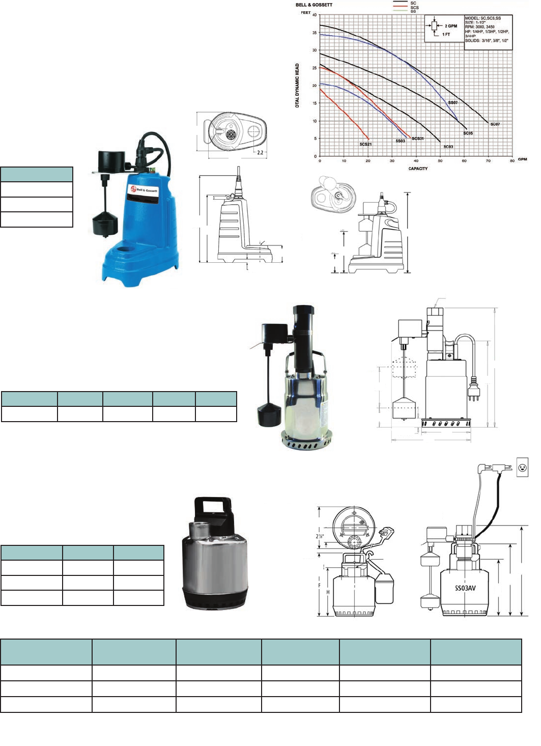
42
WASTEWATER Submersible Sump Pumps
Description
Sump pumps are specically designed for basement draining, dewatering
and water transfer. It has a range of capacities up to 70 GPM and maximum
heads of 37 TDH ranging from 1/4 HP to 3/4 HP. The stainless steel or cast
iron construction is available with 1-1/2” discharge connections. Battery
back-up sump pumps also available for emergency back up service in the
event of a power outage.
Part Number W1 (in.) W2 (in.) H1 (in.) H3 (in.)
SCS31V 5.9 9.6 10.4 15.1
Part Number F H
SS0311AT 9-3/4 7-5/8
SS0711ATF 11-1/4 9-1/8
SS0311AV 9-3/4 7-5/8
SCS
Specications
• Maximum solids: 3/16” spherical
• Manual operation available
SC
Specications
• Maximum solids 1/2”
SS
Specications
• Maximum solids: 3/8” spherical
Submersible
Sump Pumps NPT Discharge Solids Handling Capacities Maximum Head Housing Material
Construction
SC 1-1/2” 1/2” 70 GPM 37 feet TDH Cast Iron
SCS 1-1/2” 3/8” 38 GPM 25 feet TDH Stainless Steel
SS 1-1/2” 3/8” 55 GPM 34 feet TDH Stainless Steel
Part Number
SC0311AV
SC0511AV
SC0711AV
6 1/8” DIA.
1 1/2” NPT
DISCHARGE
POWER CORD:
16/3 SJTW WITH
THREE PRONG
GROUNDING PLUG
12”
F
H
SC05 and SC07
9.6”
6.4”
15.4”
12”
.6”
3.1”
1-1/2” NPT
DISCHARGE
SC03
3.5”
PUMP
ON 14”
8”
PUMP
OFF
1-1/2” NPT
H2
H1
W1
W2
1” MIN.
6”
ON
2.5”
OFF
Performance Chart
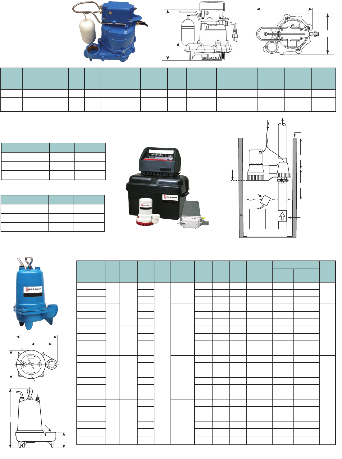
43
WASTEWATER Submersible Sump Pumps
GSP0311
From Goulds Water
Technology
Cast Iron
Sump Pump
Model
Number
Part
Number HP Volts Amps
Min.
Circuit
Breaker
Phase
Float
Switch
Style
Cord
Length
Discharge
Connection
Min.
On
Level
Min.
Off
Level
Min.
Basin
Diameter
Max.
Solids
Size
Shipping
Weight
GSP GSP0311 1/3 115 10 15A 1 Vertical 9’ 1-1/2” 7-1/4” 3-1/2” 1’ 1/2” 27 lbs
GSP GSP0311M 1/3 115 10 15A 1 Not
Supplied 9’ 1-1/2” — — 1’ 1/2” 27 lbs
2WT Sewage Effluent Pump
BBSP Battery Back-up Sump Pump
12"
8
1
/
4
"
KICK-BACK
6
1
/
4
"
19"
5
3
/
4
"
2" NPT
ROTATION
105/9”
75/9”
Discharge Heights GPH Battery Life
5’ 2250 7 hours
10’ 1500 8 hours
13’ 1000 9 hours
BBSP Performance Chart
Discharge Heights GPH Battery Life
5’ 1380 9 hours
10’ 900 9 hours
13’ 480 11 hours
Part
Number HP Phase Volts RPM Impeller
Dia. (in.)
Max.
Amps LRA KVA
Code
Full Load
Motor Eff.
Resistance Wt.
(lbs.)
Start Line-Line
2WT0311
0.33
1
115
1750
4.69
10.7 30.0 M 54 11.9 1.7
632WT0318 208 6.8 19.5 K 51 9.1 4.2
2WT0312 230 4.9 14.1 L 53 14.5 8.0
2WT0511
0.5
115
5.00
14.5 31.1 J 55 9.3 1.4
65
2WT0518 208 8.0 19.5 K 51 9.1 4.2
2WT0512 230 7.3 16.5 J 54 11.7 5.6
2WT0538
3
200 3.8 12.3 K 75 NA 6.7
2WT0532 230 3.3 9.7 K 75 NA 9.9
2WT0534 460 1.7 4.9 K 75 NA 39.4
2WT0537 575 1.4 4.3 K 68 NA 47.8
2WT0718
0.75
1208
5.38
11.0 39.0 K 65 2.6 1.4
85
2WT0712 230 9.4 24.8 J 57 4.8 2.3
2WT0738
3
200 4.1 21.2 H 74 NA 4.3
2WT0732 230 3.6 17.3 J 76 NA 5.6
2WT0734 460 1.8 8.9 J 76 NA 22.4
2WT0737 575 1.5 7.3 J 71 NA 29.2
2WT1018
1
1208
5.75
14.0 39.0 K 65 2.6 1.4
2WT1012 230 12.3 30.5 H 60 4.3 1.8
2WT1038
3
200 6.0 21.2 H 74 NA 4.3
2WT1032 230 5.8 17.3 J 76 NA 5.6
2WT1034 460 2.9 8.9 J 76 NA 22.4
2WT1037 575 2.4 7.3 J 71 NA 29.2
12"
8
1
/
4
"
KICK-BACK
6
1
/
4
"
19"
5
3
/
4
"
2" NPT
ROTATION
C
L
Standard Installation
TEE
SW
FLOAT
SW
BACK UP
PUMP
11⁄2
MAX.
SUMP CHECK VALVE
Must be installed to
prevent recirculation
into sump.
“ON” POSITION
(Primary pump normal
high water level)
TOP OF SUMP
2" MIN.
1.6 REF.
11⁄2
MAX.
2" MIN.
101/8”
31/4”
BBSP2 Performance Chart
Specifications
Specifications
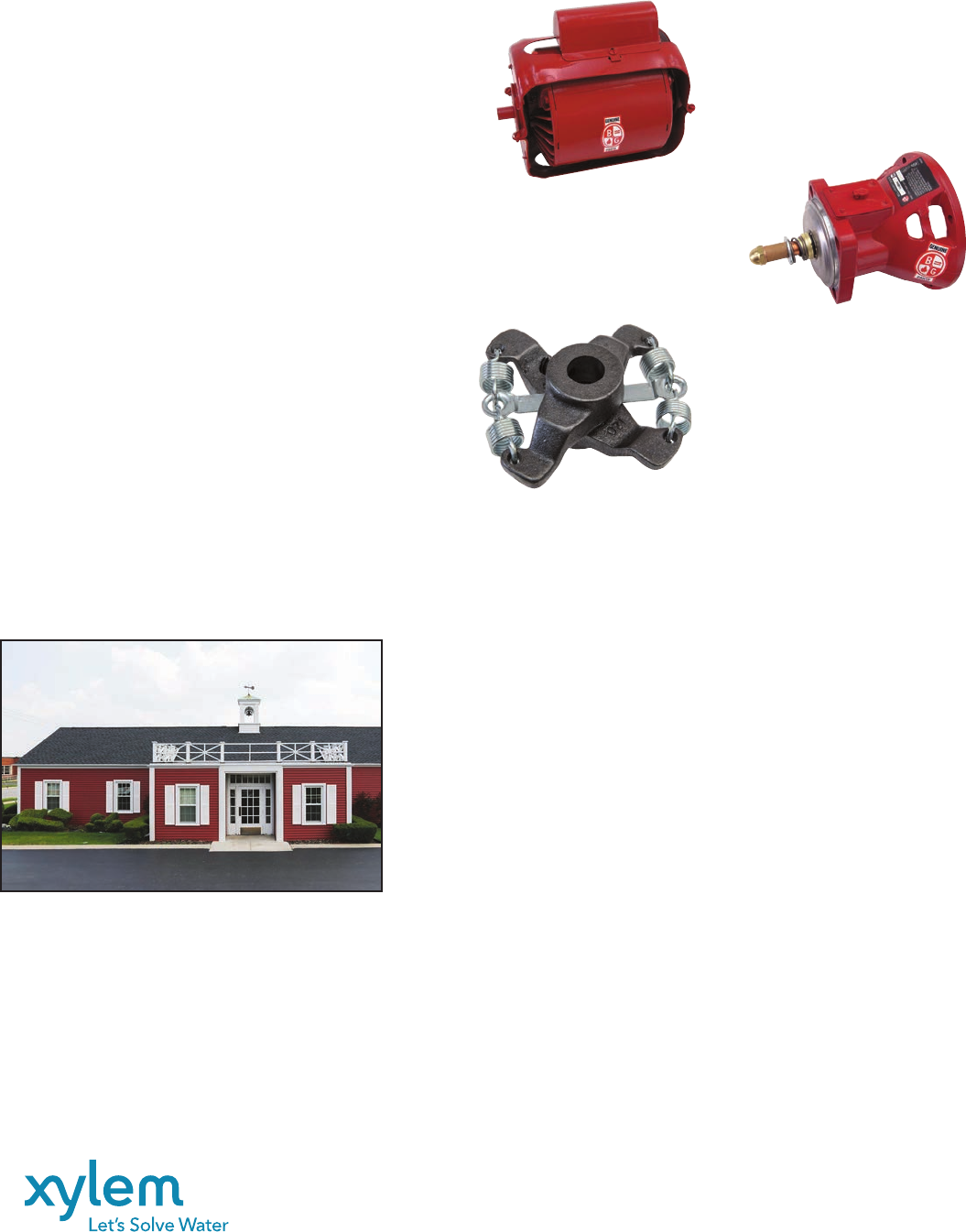
Bell & Gossett is a trademark of Xylem Inc. or one of its subsidiaries.
© 2016 Xylem Inc. A-50R April 2016
Xylem Inc.
8200 N. Austin Avenue
Morton Grove, Illinois 60053
Phone: (847) 966-3700
Fax: (847) 965-8379
www.bellgossett.com
The Little Red Schoolhouse® - Training the Industry
Genuine Bell & Gossett Parts
When replacing parts in your customers’ B&G booster or other
hydronic specialties, don’t settle for anything other than genuine
B&G parts. You owe it to your customers and to yourself to do it
right the first time.
Bell & Gossett parts are designed and engineered strictly for the
Bell & Gossett boosters. Substitute parts may seem to cost less.
But more often than not, they actually cost a lot more, when they
do not hold up on the job. Then you are faced with callbacks and
your reputation is at stake.
So why risk having to replace a replacement part?
Stick with the real thing — from Bell & Gossett.
Visit our website at
www.bellgossett.com
Go to ESP Plus and click on Sizing &
Selection Tools to use ESP Parts, to view an
exploded drawing and bill of material.
B&G designs our own motors
to exacting circulating pump
specifications.
B&G bearing assembly bracket.
Restores pump to like
new conditions.
B&G flexible spring coupler
dampens vibration and noise.
Bell & Gossett has long been known for its dedication to
training. The “Little Red Schoolhouse
®
“ has graduated over
60,000 students since it was founded in 1954.
Graduates from the “Little Red Schoolhouse” may be found
throughout North America, Europe, Africa, Asia and Australia.
For applications to attend these seminars, please contact
a Bell & Gossett Representative in your area. They will
have the schedule dates for all seminars and will make all
the arrangements for you. As a service and a continuing
educational source to the HVAC industry, these seminars are
offered free of charge. IACET certified CEU credits are awarded
for each seminar.
* The USGBC has approved the technical and instructional
quality of the Modern Hydronic Heating Systems - Basic
Seminar (15 GBCI CE Hours) and the Large Chilled Water
Design Seminar (11 GBCI CE Hours). These courses are
approved for GBCI Continuing Education Hours towards
LEED Credential Maintenance Programs.
Seminars currently offered are:
• Modern Hydronic System Design - Basic*
• Modern Hydronic System Design - Advanced*
• Design & Application of Water Based HVAC Systems
• Large Chilled Water System Design*
• Pump Service & Maintenance School
• Steam Systems Design & Applications
• Steam System Operation & Maintenance
• Plumbing Systems Design
