550810 5 Goulds (100 275H) 6 Inch And Larger High Capacity Pump End Technical Data Fundamentals
550829 5 Goulds Xtreme Duty Motors Single Phase Water Products Technical Data And Pump Fundamentals 550829_5_Goulds Xtreme Duty Motors Single Phase Water Products Technical Data and Pump Fundamentals
550826 5 Goulds Xtreme Duty Motors Single Phase Water Products Technical Data And Pump Fundamentals 550826_5_Goulds Xtreme Duty Motors Single Phase Water Products Technical Data and Pump Fundamentals
550831 5 Goulds Xtreme Duty Motors Single Phase Water Products Technical Data And Pump Fundamentals 550831_5_Goulds Xtreme Duty Motors Single Phase Water Products Technical Data and Pump Fundamentals
551073 4 Goulds Bf03S Shallow Well Jet Pump Water Products Technical Data 551073_4_Goulds BF03S Shallow Well Jet Pump Water Products Technical Data
551095 6 Goulds J05X Convertible Pump-Tank Package Data Sheet 551095_6_Goulds J05X Convertible Pump-Tank Package data sheet
: Pump 550810 5 Goulds (100-275H) 6 Inch And Larger High Capacity Pump End Technical Data And Pump Fundamentals 550810_5_Goulds (100-275H) 6 Inch And Larger High Capacity Pump End Technical Data And Pump Fundamentals pdf
Open the PDF directly: View PDF ![]() .
.
Page Count: 56
Water Products
Technical Data and Pump Fundamentals
FOR GOULDS WATER TECHNOLOGY, BELL & GOSSETT, RED JACKET SERIES AND CENTRIPRO
TECHNICAL MANUAL
TTECHWP R3

PAGE 2
Residential Water Systems
Goulds Water Technology,
Bell & Gossett, Red Jacket Series, CentriPro
TECHNICAL DATA
Friction loss ................................................................... 1-4
Website Addresses .......................................................... 5
Jet and Submersible Pump Selection
Private Residences, Yard Fixtures, Public Buildings,
Farm Use, Boiler Feed Requirements ........................6
Tank Selection .............................................................. 7-9
Centrifugal Pump Fundamentals
NPSH and Cavitation, Vapor Pressure of Water ...10-12
Electrical Data
NEMA Panel Enclosures ................................................13
General Data
Determining Water Level ..............................................14
Use of Tail Pipe with Jet Pumps .................................... 15
Determining Flow Rates ..........................................16-17
Theoretical Discharge of Nozzles in
U.S. Gallons per Minute..............................................17
Terms and Usable Formulas
Calculating Suction Lift ..................................................19
Denitions ....................................................................... 20
Basic Formulas ...............................................................20
Afnity Laws ....................................................................22
Conversion Charts ...................................................23-26
Pipe Volume and Velocity
Storage of Water in Various Size Pipes ........................27
Minimum Flow to Maintain 2 Ft./Sec. ..........................27
Storage of Water in Various Sizes of Wells .................27
Motor Data
A.O. Smith Motor Data and Parts .................................28
Terminal Board and Voltage Change Plug .................29
Capacitor Start Induction Run – Motor Wiring ...........29
Emerson Motor Wiring
115/230 Voltage ............................................................30
Pressure Switch Wiring and Adjustments
CentriPro® and Square “D” Switches ............................ 31
Furnas Pro Control .........................................................31
Wiring Diagrams AWA501, AWA502 .................... 32-33
Preventing a Suction Vortex .......................................... 34
Check Valve - Operation, Water Hammer,
Maintenance .......................................................... 35-36
PUMP FUNDAMENTALS
Sources of Water - Well Types ......................................37
Typical Pump Installations ....................................... 38-40
Booster and Low Yield Well Installations .............. 41-43
Pump Types, Motors, Tanks and Accessories .......44-46
Pump System Sizing Questions and Answers ...... 47-53
INDEX
PAGE 1
Residential Water Systems
Goulds Water Technology,
Bell & Gossett, Red Jacket Series, CentriPro
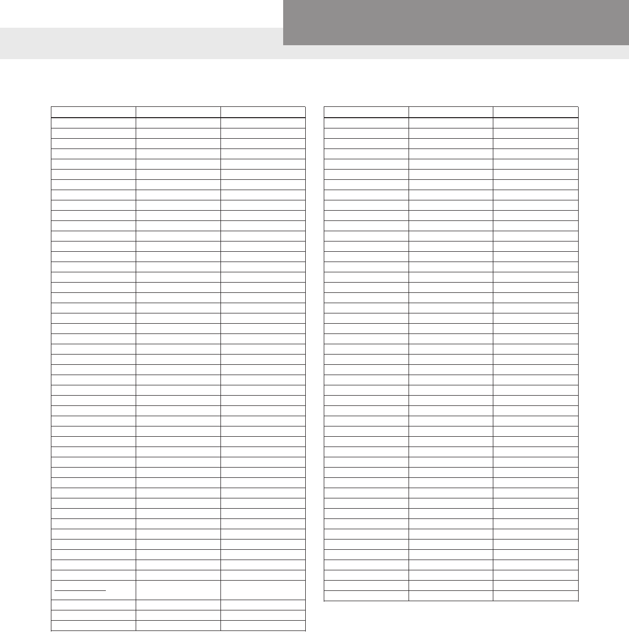
SCH 40 – PLASTIC PIPE: FRICTION LOSS (IN FEET OF HEAD) PER 100 FT.
GPM GPH 3⁄8" ½" ¾" 1" 1¼" 1½" 2" 2½" 3" 4" 6" 8" 10"
ft. ft. ft. ft. ft. ft. ft. ft. ft. ft. ft. ft. ft.
1 60 4.25 1.38 .356 .11
2 120 15.13 4.83 1.21 .38 .10
3 180 31.97 9.96 2.51 .77 .21 .10
4 240 54.97 17.07 4.21 1.30 .35 .16
5 300 84.41 25.76 6.33 1.92 .51 .24
6 360 36.34 8.83 2.69 .71 .33 .10
8 480 63.71 15.18 4.58 1.19 .55 .17
10 600 97.52 25.98 6.88 1.78 .83 .25 .11
15 900 49.68 14.63 3.75 1.74 .52 .22
20 1,200 86.94 25.07 6.39 2.94 .86 .36 .13
25 1,500 38.41 9.71 4.44 1.29 .54 .19
30 1,800 13.62 6.26 1.81 .75 .26
35 2,100 18.17 8.37 2.42 1.00 .35 .09
40 2,400 23.55 10.70 3.11 1.28 .44 .12
45 2,700 29.44 13.46 3.84 1.54 .55 .15
50 3,000 16.45 4.67 1.93 .66 .17
60 3,600 23.48 6.60 2.71 .93 .25
70 4,200 8.83 3.66 1.24 .33
80 4,800 11.43 4.67 1.58 .41
90 5,400 14.26 5.82 1.98 .52
100 6,000 7.11 2.42 .63 .08
125 7,500 10.83 3.80 .95 .13
150 9,000 5.15 1.33 .18
175 10,500 6.90 1.78 .23
200 12,000 8.90 2.27 .30
250 15,000 3.36 .45 .12
300 18,000 4.85 .63 .17
350 21,000 6.53 .84 .22
400 24,000 1.08 .28
500 30,000 1.66 .42 .14
550 33,000 1.98 .50 .16
600 36,000 2.35 .59 .19
700 42,000 .79 .26
800 48,000 1.02 .33
900 54,000 1.27 .41
950 57,000 .46
1000 60,000 .50
NOTE: See page 5 for website addresses for pipe manufacturers – there are many types of new plastic pipe available now.
FRICTION LOSS

PAGE 2
Residential Water Systems
Goulds Water Technology,
Bell & Gossett, Red Jacket Series, CentriPro
STEEL PIPE: FRICTION LOSS (IN FEET OF HEAD) PER 100 FT.
GPM GPH 3⁄8" ½" ¾" 1" 1¼" 1½" 2" 2½" 3" 4" 5" 6" 8" 10"
ft. ft. ft. ft. ft. ft. ft. ft. ft. ft. ft. ft. ft. ft.
1 60 4.30 1.86 .26
2 120 15.00 4.78 1.21 .38
3 180 31.80 10.00 2.50 .77
4 240 54.90 17.10 4.21 1.30 .34
5 300 83.50 25.80 6.32 1.93 .51 .24
6 360 36.50 8.87 2.68 .70 .33 .10
7 420 48.70 11.80 3.56 .93 .44 .13
8 480 62.70 15.00 4.54 1.18 .56 .17
9 540 18.80 5.65 1.46 .69 .21
10 600 23.00 6.86 1.77 .83 .25 .11 .04
12 720 32.60 9.62 2.48 1.16 .34 .15 .05
15 900 49.70 14.70 3.74 1.75 .52 .22 .08
20 1,200 86.10 25.10 6.34 2.94 .87 .36 .13
25 1,500 38.60 9.65 4.48 1.30 .54 .19
30 1,800 54.60 13.60 6.26 1.82 .75 .26
35 2,100 73.40 18.20 8.37 2.42 1.00 .35
40 2,400 95.00 23.50 10.79 3.10 1.28 .44
45 2,700 30.70 13.45 3.85 1.60 .55
70 4,200 68.80 31.30 8.86 3.63 1.22 .35
100 6,000 62.20 17.40 7.11 2.39 .63
150 9,000 38.00 15.40 5.14 1.32
200 12,000 66.30 26.70 8.90 2.27 .736 .30 .08
250 15,000 90.70 42.80 14.10 3.60 1.20 .49 .13
300 18,000 58.50 19.20 4.89 1.58 .64 .16 .0542
350 21,000 79.20 26.90 6.72 2.18 .88 .23 .0719
400 24,000 103.00 33.90 8.47 2.72 1.09 .279 .0917
450 27,000 130.00 42.75 10.65 3.47 1.36 .348 .114
500 30,000 160.00 52.50 13.00 4.16 1.66 .424 .138
550 33,000 193.00 63.20 15.70 4.98 1.99 .507 .164
600 36,000 230.00 74.80 18.60 5.88 2.34 .597 .192
650 39,000 87.50 21.70 6.87 2.73 .694 .224
700 42,000 101.00 25.00 7.93 3.13 .797 .256
750 45,000 116.00 28.60 9.05 3.57 .907 .291
800 48,000 131.00 32.40 10.22 4.03 1.02 .328
850 51,000 148.00 36.50 11.50 4.53 1.147 .368
900 54,000 165.00 40.80 12.90 5.05 1.27 .410
950 57,000 184.00 45.30 14.30 5.60 1.41 .455
1000 60,000 204.00 50.20 15.80 6.17 1.56 .500
FRICTION LOSS

PAGE 3
Residential Water Systems
Goulds Water Technology,
Bell & Gossett, Red Jacket Series, CentriPro
COPPER PIPE: FRICTION LOSS (IN FEET OF HEAD) PER 100 FT.
GPM GPH 3⁄8" ½" ¾" 1" 1¼" 1½" 2" 2½" 3" 4"
ft. ft. ft. ft. ft. ft. ft. ft. ft. ft.
1 60 6.2 1.8 .39
2 120 19.6 6.0 1.2
5 300 30.0 5.8 1.6
7 420 53.0 11.0 3.2 2.2
10 600 19.6 5.3 3.9
15 900 37.0 9.9 6.2 2.1
18 1,080 55.4 16.1 6.9 3.2
20 1,200 18.5 10.4 3.9
25 1,500 27.7 14.3 5.3 1.5
30 1,800 39.3 18.7 7.6 2.1
35 2,100 48.5 25.4 10.2 2.8
40 2,400 30.0 13.2 3.5 1.2
45 2,700 39.3 16.2 4.2 1.6
50 3,000 19.4 5.1 1.8
60 3,600 27.7 6.9 2.5 1.1
70 4,200 40.0 9.2 3.5 1.4
75 4,500 41.6 9.9 3.7 1.6
80 4,800 45.0 11.6 4.2 1.8
90 5,400 50.8 13.9 4.8 2.2
100 6,000 16.9 6.2 2.8
125 7,500 25.4 8.6 3.7
150 9,000 32.3 11.6 4.8 1.2
175 10,500 41.6 16.2 6.9 1.7
200 12,000 57.8 20.8 9.0 2.2
250 15,000 32.3 13.9 3.5
300 18,000 41.6 18.5 4.6
350 21,000 32.3 5.8
400 24,000 39.3 7.2
450 27,000 44.0 9.2
500 30,000 11.1
750 45,000 23.1
1000 60,000 37.0
FRICTION LOSS
RUBBER HOSE: FRICTION LOSS (IN FEET OF HEAD) PER 100 FT.
Actual Inside Diameter in Inches
GPM ¾" 1" 1¼" 1½" 2" 2½" 3" 4"
15 70 23 5.8 2.5 .9 .2
20 122 32 10 4.2 1.6 .5
25 182 51 15 6.7 2.3 .7
30 259 72 21.2 9.3 3.2 .9 .2
40 122 35 15.5 5.5 1.4 .7
50 185 55 23 8.3 2.3 1.2
60 233 81 32 11.8 3.2 1.4
70 104 44 15.2 4.2 1.8
80 134 55 19.8 5.3 2.5
90 164 70 25 7 3.5 .7
100 203 85 29 8.1 4 .9
125 305 127 46 12.2 5.8 1.4
150 422 180 62 17.3 8.1 1.6
175 230 85 23.1 10.6 2.5
200 308 106 30 13.6 3.2
Actual Inside Diameter in Inches
GPM ¾" 1" 1¼" 1½" 2" 2½" 3" 4"
250 162 44 21 4.9
300 219 62 28 6.7
350 292 83 39 9.3
400 106 49 11.8
500 163 74 17.1
600 242 106 23
700 344 143 30
800 440 182 40
900 224 51
1000 270 63
1250 394 100
1500 525 141
1750 185
2000 230

PAGE 4
Residential Water Systems
Goulds Water Technology,
Bell & Gossett, Red Jacket Series, CentriPro
Example:
(A) 100 ft. of 2" plastic pipe with one (1) 90º elbow and one (1) swing check valve.
90º elbow – equivalent to 5.5 ft. of straight pipe
Swing check – equivalent to 13.0 ft. of straight pipe
100 ft. of pipe – equivalent to 100 ft. of straight pipe
118.5 ft. = Total equivalent pipe
Figure friction loss for 118.5 ft. of pipe.
(B) Assumeowtobe80GPMthrough2"plasticpipe.
1. Friction loss table shows 11.43 ft. loss per 100 ft. of pipe.
2. In step (A) above we have determined total ft. of pipe to be 118.5 ft.
3. Convert 118.5 ft. to percentage 118.5 ÷ 100 = 1.185
4. Multiply 11.43
x 1.185
13.54455 or 13.5 ft.=Totalfrictionlossinthissystem.
OFFSET JET PUMP PIPE FRICTION
Where the jet pump is offset horizontally from the well site, add the additional friction loss from the chart below to the vertical lift to approxi-
mate what capacity the pump will produce.
EQUIVALENT NUMBER OF FEET STRAIGHT PIPE FOR DIFFERENT FITTINGS
① Therearemanynew,fullportvalvedesignsavailabletodaywhicharemoreefcientandcreatemuchlessfrictionloss,consultwithvalvesuppliersfornewdata.
FRICTION LOSS
Size of ttings, Inches ½" ¾" 1" 1¼" 1½" 2" 2½" 3" 4" 5" 6" 8" 10"
90° Ell 1.5 2.0 2.7 3.5 4.3 5.5 6.5 8.0 10.0 14.0 15 20 25
45° Ell 0.8 1.0 1.3 1.7 2.0 2.5 3.0 3.8 5.0 6.3 7.1 9.4 12
Long Sweep Ell 1.0 1.4 1.7 2.3 2.7 3.5 4.2 5.2 7.0 9.0 11.0 14.0
Close Return Bend 3.6 5.0 6.0 8.3 10.0 13.0 15.0 18.0 24.0 31.0 37.0 39.0
Tee-Straight Run 1 2 2 3 3 4 5
Tee-Side Inlet or Outlet
orPitlessAdapter 3.3 4.5 5.7 7.6 9.0 12.0 14.0 17.0 22.0 27.0 31.0 40.0
①BallorGlobeValveOpen 17.0 22.0 27.0 36.0 43.0 55.0 67.0 82.0 110.0 140.0 160.0 220.0
①AngleValveOpen 8.4 12.0 15.0 18.0 22.0 28.0 33.0 42.0 58.0 70.0 83.0 110.0
GateValve-FullyOpen 0.4 0.5 0.6 0.8 1.0 1.2 1.4 1.7 2.3 2.9 3.5 4.5
CheckValve(Swing) 4 5 7 9 11 13 16 20 26 33 39 52 65
InLineCheckValve(Spring)
orFootValve 4 6 8 12 14 19 23 32 43 58
PIPE FRICTION FOR OFFSET JET PUMPS
Additional Friction Loss in Feet Per 100 Feet Offset
JET SIZE
HP
SUCTION AND PRESSURE PIPE SIZES (in inches)
1¼ x 1 1¼ x 1¼ 1½ x 1¼ 1½ x 1½ 2 x 1½ 2 x 2 2½ x 2 2½ x 2½ 3 x 2½ 3 x 3
1⁄312 8 6 4
½18 12 8 6 3 2
¾22 16 11 6 4
125 16 9 6
1½
Operations Below Line
Not Recommended
13 8 5 3
220 13 7 5
313 9 6 4
NOTE: The amount of additional Friction Loss from the Table above is added to the Total Suction Lift on a Shallow Well System or the
Depth to Jet Assembly on a Deep Well System.
Example: If using a 1 HP jet pump with a 150’ offset from a deep well. Using 1 ½” and 1 ½” pipes will be the same as having an extra 16’
of lift per 100’ of pipe, so with a 150’ offset (150’/100’ = 1.5), you will have 1.5 x 16’ = 24’ of additional lift. Add the 24’ to the Depth to Jet
Assembly to see what the performance will be. If you upsize to 2” & 2” pipe the additional friction loss will only be 1.5 x 6’ = 9’.

PAGE 5
Residential Water Systems
Goulds Water Technology,
Bell & Gossett, Red Jacket Series, CentriPro
WEBSITE ADDRESSES FOR PIPE MANUFACTURERS, CHECK VALVE
INFORMATION AND XYLEM
Pipe and Plastic Well Casing Manufacturer’s
websites:
www.shur-align.com or www.modernproducts.net
• Drop pipe - many types
www.certainteed.com
• Kwik-set® threaded drop pipe in Sch 80 and
120
• Solvent weld pressure pipe in Sch 40 and 80,
class 160 (SDR26), class 200 (SDR 21) and
class 315 (SDR 13.5)
• PVC sewer and drain pipe
www.pweaglepipe.com
• PW Eagle PVC Pipe - many types
TECHNICAL DATA
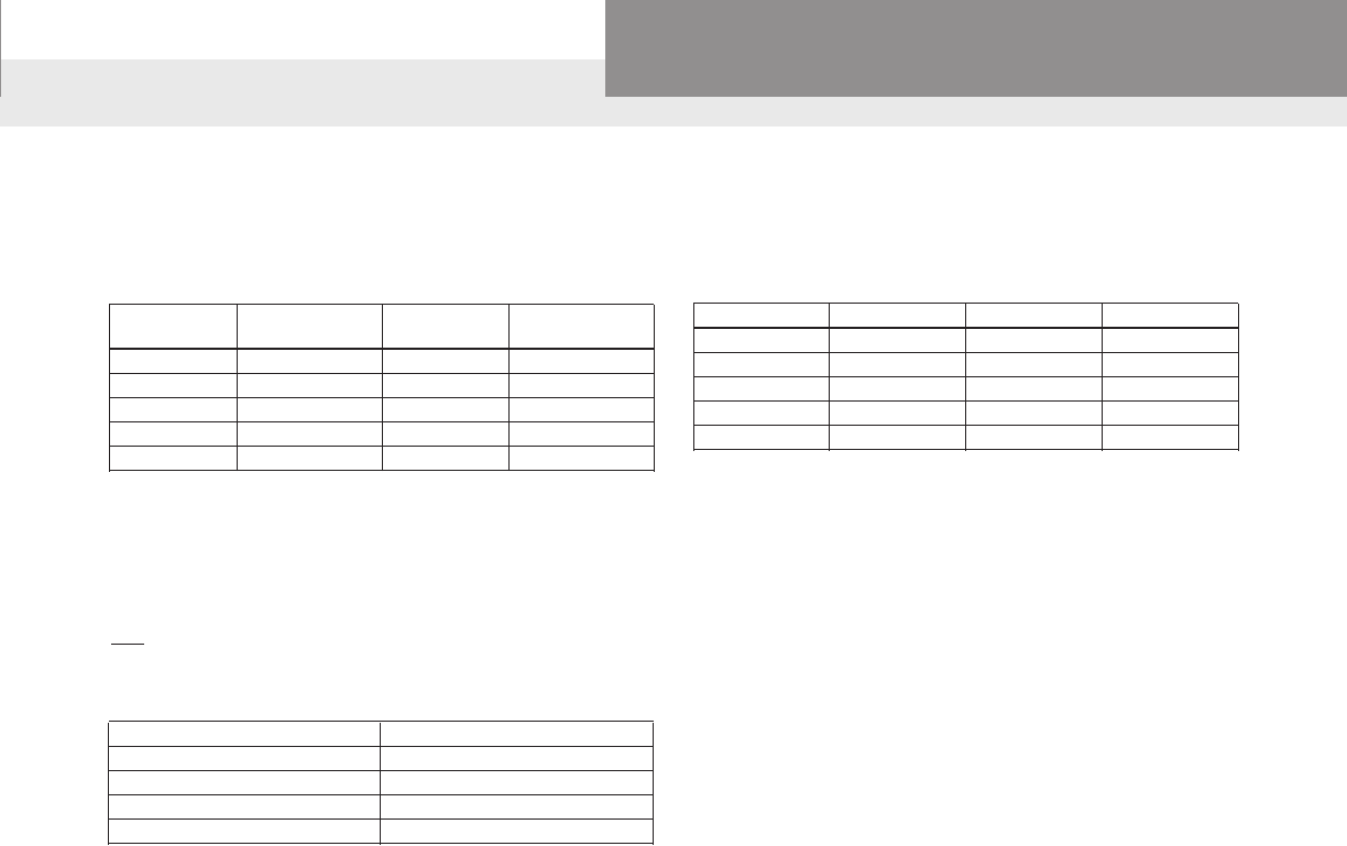
TUBING DIMENSIONS AND WEIGHTS
(ASTM F 876/877)
Size (in.) Outside Diameter
(in.)
Weight
(lbs./ft. of tubing)
3/8 0.500 0.0413
1/2 0.625 0.0535
3/4 0.875 0.1023
1 1.125 0.1689
FRICTION LOSSES
Insert tting friction losses are shown in table below.
Consult manufacturer for other tting friction losses.
METAL INSERT FITTING FRICTION LOSS
Type of
Fitting
Equivalent Length of Tubing (ft.)
3/8" size 1/2" size 3/4" size 1" size
Coupling 2.9 2.0 0.6 1.3
Elbow 90º 9.2 9.4 9.4 10.0
Tee-branch 9.4 10.4 8.9 11.0
Tee-run 2.9 2.4 1.9 2.3
* 1" ttings have an increased total length
FRICTION LOSS AND VELOCITY VS. FLOW RATE PEX PLUMBING TUBING (CTS) (ASTM F-876/877)
Tubing water ow rate, velocity and frictional losses are given in the following table. Long-radius tubing bends have the
same head loss as straight tubing.
Nominal Size
Average ID 3/8" 0.350 1/2" 0.475 3/4" 0.671 1" 0.863
GPM Friction Loss Velocity Friction Loss Velocity Friction Loss Velocity Friction Loss Velocity
1 7.0 3.33 1.6 1.81 0.3 0.96 0.1 0.55
2 25.4 6.67 5.8 3.62 1.1 1.81 0.3 1.10
3 53.9 10.00 12.2 5.43 2.3 2.72 0.7 1.65
4 91.8 13.34 20.8 7.24 3.9 3.63 1.1 2.19
5 31.4 9.05 5.9 4.54 1.7 2.74
6 44.0 10.86 8.2 5.44 2.4 3.29
7 58.6 12.67 10.9 6.35 3.2 3.84
8 14.0 7.26 4.1 4.39
9 17.4 8.17 5.1 4.94
10 21.1 9.07 6.2 5.48
11 25.2 9.98 7.4 6.03
12 29.6 10.89 8.7 6.58
13 34.3 11.79 10.1 7.13
14 39.4 12.70 11.6 7.68
15 13.2 8.23
16 14.8 8.78
NOTE: Friction Loss based on Hazen-Williams Formula (C=150). CTS Tubing manufactured per ASTM F-876/877. Friction Loss - psi per 100 ft. of tubing. Velocity
(VEL) feet per second.
Check Valve Manufacturer’s websites:
www.omatic.com
• Danfoss Flomatic Valves
www.simmonsmfg.com
• Simmons Mfg.
Xylem Inc.:
www.gouldswatertechnology.com
• Goulds Water Technology Water and
Wastewater Products
www.centripro.com
• CentriPro Accessories, Motors and Control
Boxes and Wastewater Panels

PAGE 6
Residential Water Systems
Goulds Water Technology,
Bell & Gossett, Red Jacket Series, CentriPro
JET AND SUBMERSIBLE PUMP SELECTION
PRIVATE RESIDENCES
Total Usage Bathrooms in Home
Outlets Flow Rate GPM Gallons 1 1½ 2-2 ½ 3-4
Shower or Bathtub 5 35 35 35 53 70
Lavatory 4 2 2 4 6 8
Toilet 4 5 5 10 15 20
Kitchen Sink 5 3 3 3 3 3
Automatic Washer 5 35 – 18 18 18
Dishwasher 2 14 – – 3 3
Normal seven minute* 45 70 98 122
peak demand (gallons)
Minimumsizedpumprequired
tomeetpeakdemandwithout 7GPM(420GPH) 10GPM(600GPH) 14GPM(840GPH) 17GPM(1020GPH)
supplementalsupply
Notes:
Valuesgivenareaverageanddonotincludehigherorlowerextremes.
*Peakdemandcanoccurseveraltimesduringmorningandeveninghours.
**Countthenumberofxturesinahomeincludingoutsidehosebibs.Supplyonegallonperminuteeach.
YARD FIXTURES
GardenHose–½" 3GPM
GardenHose–¾" 6GPM
Sprinkler–Lawn 3-7GPM
PUBLIC BUILDINGS
Pump Capacity Required in U.S. Gallons per Minute
per xture for Public Buildings
Total Number of Fixtures
Type of Building 25 or 26- 51- 101- 201- 401- Over
Less 50 100 200 400 600 600
Hospitals 1.00 1.00 .80 .60 .50 .45 .40
MercantileBuildings 1.30 1.00 .80 .71 .60 .54 .48
OfceBuildings 1.20 .90 .72 .65 .50 .40 .35
Schools 1.20 .85 .65 .60 .55 .45
Hotels,Motels .80 .60 .55 .45 .40 .35 .33
Apartment Buildings .60 .50 .37 .30 .28 .25 .24
1. Forlessthan25xtures,pumpcapacityshouldnotbelessthan75%ofcapacity
requiredfor25xtures.
2. Whereadditionalwaterisrequiredforsomespecialprocess,thisshouldbeaddedto
pumpcapacity.
3. Wherelaundriesorswimmingpoolsaretobesupplied,addapproximately10%to
pumpcapacityforeither.
4. Whereadditionaloccupancyisgreaterthannormal,addapproximately20%topump
capacity.
FARM USE
Horse,Steer 12Gallonsperday
DryCow 15Gallonsperday
MilkingCow 35Gallonsperday
Hog 4Gallonsperday
Sheep 2Gallonsperday
Chickens/100 6Gallonsperday
Turkeys/100 20Gallonsperday
Fire 20-60GPM
BOILER FEED REQUIREMENTS
Boiler Boiler Boiler Boiler Boiler
HP GPM HP GPM HP GPM HP GPM HP GPM
20 1.38 55 3.80 90 6.21 160 11.1 275 19.0
25 1.73 60 4.14 100 6.90 170 11.7 300 20.7
30 2.07 65 4.49 110 7.59 180 12.4 325 22.5
35 2.42 70 4.83 120 8.29 190 13.1 350 24.2
40 2.76 75 5.18 130 8.97 200 13.8 400 27.6
45 3.11 80 5.52 140 9.66 225 15.5 450 31.1
50 3.45 85 5.87 150 10.4 250 17.3 500 34.5
1. BoilerHorsepowerequals34.5lb.waterevaporatedatandfrom212ºF,andrequires
feed water at a rate of 0.069 gpm.
Selecttheboilerfeedpumpwithacapacityof2to3timesgreaterthantheguresgiven
aboveatapressure20to25%abovethatofboiler,becausethetablegivesequivalents
ofboilerhorsepowerwithoutreferencetouctuatingdemands.
PAGE 7
Residential Water Systems
Goulds Water Technology,
Bell & Gossett, Red Jacket Series, CentriPro
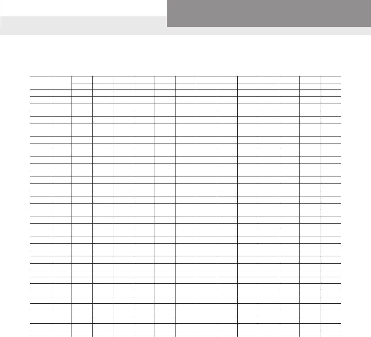
TABLE 2 – PRESSURE FACTORS
Pump Cut-In Pressure – PSIG
20 25 30 35 40 45 50 55 60 65 70 75 80 85 90 95 100 105 110 115
30 .22
35 .30 .20
40 .37 .27 .18
45 .42 .34 .25 .17
50 .46 .39 .31 .23 .15
55 .50 .43 .36 .29 .22 .14
60 .54 .47 .40 .33 .27 .20 .13
65 .50 .44 .38 .31 .25 .19 .13
70 .53 .47 .41 .35 .30 .24 .18 .12
75 .50 .45 .39 .33 .28 .22 .17 .11
80 .53 .48 .42 .37 .32 .26 .21 .16 .11
85 .50 .45 .40 .35 .30 .25 .20 .15 .10
90 .53 .48 .43 .38 .33 .29 .24 .19 .14 .10
95 .50 .46 .41 .36 .32 .27 .23 .18 .14 .09
100 .52 .48 .44 .39 .35 .31 .26 .22 .17 .13 .09
105 .50 .46 .42 .38 .33 .29 .25 .21 .17 .13 .08
110 .52 .46 .44 .40 .36 .32 .28 .24 .20 .16 .12
115 .50 .46 .42 .39 .35 .31 .27 .23 .19 .15 .12 .06
120 .52 .48 .45 .41 .37 .33 .30 .26 .22 .19 .15 .11
125 .50 .47 .43 .39 .36 .32 .29 .25 .21 .16 .14 .11 .07
Todeterminetankdrawdownofoperatingpressurerangesotherthanthoselistedintable,usefollowingprocedure:
Multiplytotaltankvolume(table1)bypressurefactor(table4).
Example:Operatingrange:35/55
Tankbeingused:V-200
65.1 = Total volume of tank (table 1)
x.29 Pressurefactor(table4)
18.9= Drawdowningallonsat35/55PSIoperatingrange.
Pump Cut-Out Pressure – PSIG
TABLE 1 – TANK MODELS – SeeyourFullLineCatalogTankBulletinsforalistingofallavailablemodels.
① Drawdown based on a 22 psi differential and Boyle’s Law. Temperature,
elevation and pressure can all affect drawdown volume.
V6P 2.0 0.8 0.7 0.6 1.2
V15P 4.5 1.8 1.5 1.3 2.7
V25P 8.2 3.3 2.8 2.4 4.5
V45P 13.9 5.6 4.7 4.1 8.4
V45B 13.9 5.6 4.7 4.1 8.4
V45 13.9 5.6 4.7 4.1 8.4
V60B 19.9 8.0 6.8 5.8 12.1
V60 19.9 8.0 6.8 5.8 12.1
V80 25.9 10.4 8.8 7.6 13.9
V80EX 25.9 10.4 8.8 7.6 13.9
V100 31.8 12.8 10.8 9.4 13.8
V100S 31.8 12.8 10.8 9.4 13.8
V140B 45.2 18.2 15.4 13.3 27.3
V140 45.2 18.2 15.4 13.3 27.3
V200B 65.1 26.2 22.1 19.2 39.3
V200 65.1 26.2 22.1 19.2 39.3
V250 83.5 33.6 28.4 25.6 50.8
V260 84.9 34.1 28.9 25.0 44.7
V350 115.9 46.6 39.4 34.1 70.5
Model
No.
Total
Volume
(Gals.)
① Drawdown in Gals. at System
Operating Pressure Range of
18/40 28/50 38/60
PSIG PSIG PSIG
Maximum
Drawdown
Vol. (Gals.)
HYDROPRO AND CENTRIPRO TANK SELECTION
Tank Drawdown Pressure Factors Using an
“Extra” 2 PSI of Drawdown
Pressure Differential Factor with extra 2 psi*
18 – 40 .402
28 – 50 .340
38 – 60 .295
48 – 70 .260
ToCalculatedrawdowncapacitymultiply:FactorxTankVolume.
PAGE 8
Residential Water Systems
Goulds Water Technology,
Bell & Gossett, Red Jacket Series, CentriPro
90
80
70
60
50
40
30
20
10
Gauge
Pressure
lb./sq. in.
Percent of
Tank Volume
100
80
60
50
40
35
30
25
20
87.2
84.5
80.3
77.3
73.2
70.4
67.2
63.0
57.7
90
70 86.0
82.7
15
10
5
50.5
40.5
25.4
15.5%
Based on an
atmospheric
pressure of
14.7 lb./sq. in.
at sea level.
Percent of Tank Height
90
80
70
60
50
40
30
20
10
Percent of Tank Height
Gauge
Pressure
lb./sq. in.
Percent
of Tank Volume
100
80
60
50
40
90
70 86.0
82.7
87.2
84.5
80.3
77.3
73.2
35 70.4
30
25 67.2
63.0
20
15 57.7
50.5
10 40.5
5 25.4
15.5%
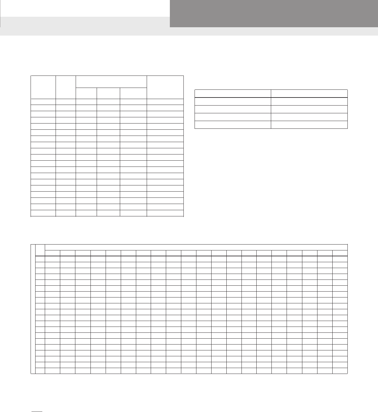
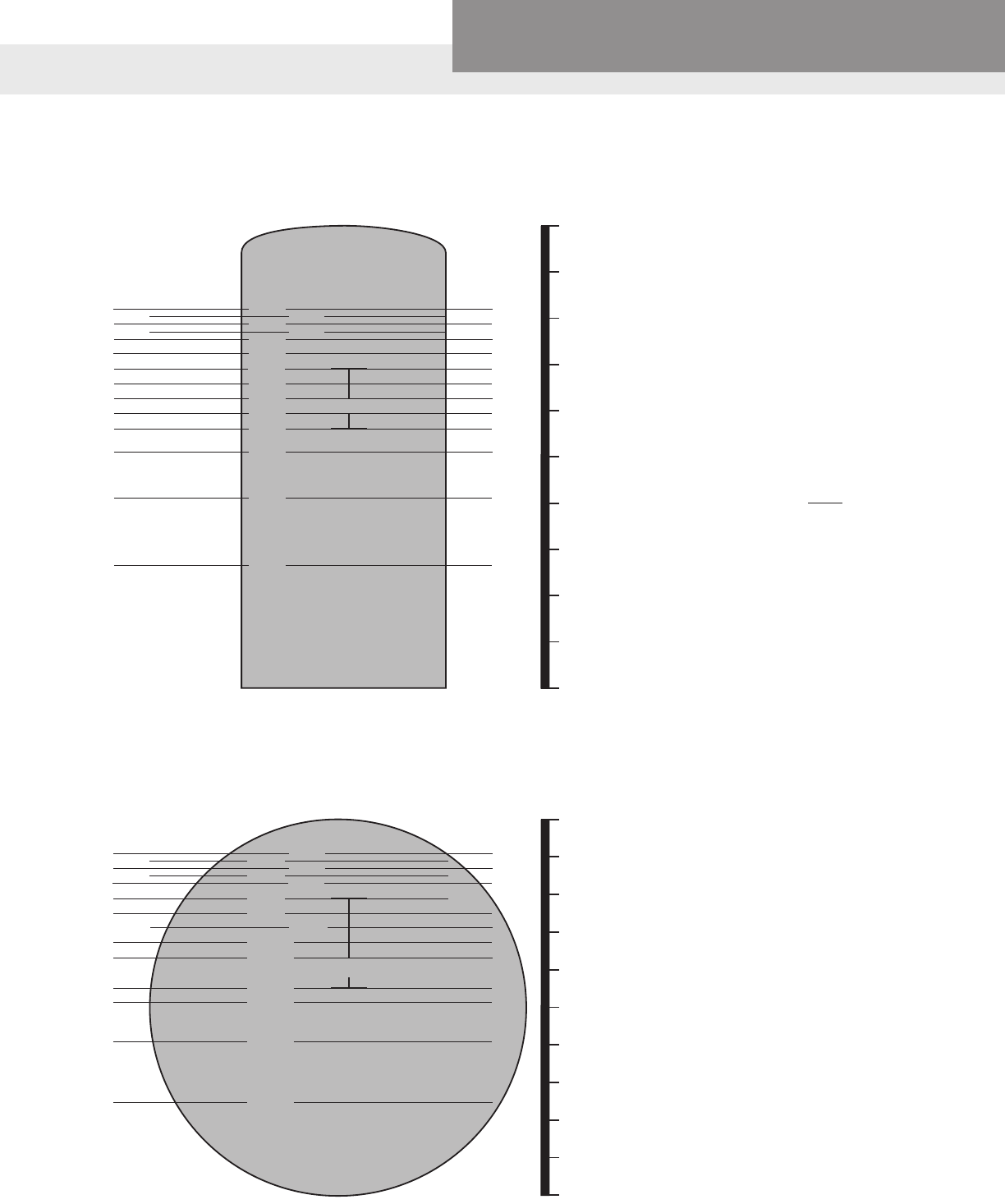
HORIZONTAL
TANK TABLE
VERTICAL
TANK TABLE
When using large standard galvanized
tanks, a constant air cushion is required for
proper operation of the water system.
The illustrations show the percent of tank
volume as related to the pressure gauge
reading. To determine the amount of water
you will receive as drawoff from the tank,
you should subtract the smaller number
from the larger number to get the percent-
age. Then multiply by the size of the tank
to get the gallons drawoff.
Example:
50 lbs. = 77.3
minus 30 lbs. = 67.2
= 10.1%
x 120 gallon size
(size of tank)
= 12.12 gallons
drawoff
TANK SELECTION

PAGE 9
Residential Water Systems
Goulds Water Technology,
Bell & Gossett, Red Jacket Series, CentriPro
Dia. in
inches
CAPACITIES OF TANKS OF VARIOUS DIMENSIONS
Length of Cylinder
1" 1' 5' 6' 7' 8' 9' 10' 11' 12' 13' 14' 15' 16' 17' 18' 20' 22' 24'
1 0.04 0.20 0.24 0.28 0.32 0.36 0.40 0.44 0.48 0.52 0.56 0.60 0.64 0.68 0.72 0.80 0.88 0.96
2 0.01 0.16 0.80 0.96 1.12 1.28 1.44 1.60 1.76 1.92 2.08 2.24 2.40 2.56 2.72 2.88 3.20 3.52 3.84
3 0.03 0.37 1.84 2.20 2.56 2.92 3.30 3.68 4.04 4.40 4.76 5.12 5.48 5.84 6.22 6.60 7.36 8.08 8.80
4 0.05 0.65 3.26 3.92 4.58 5.24 5.88 6.52 7.18 7.84 8.50 9.16 9.82 10.5 11.1 11.8 13.0 14.4 15.7
5 0.08 1.02 5.10 6.12 7.14 8.16 9.18 10.2 11.2 12.2 13.3 14.3 15.3 16.3 17.3 18.4 20.4 22.4 24.4
6 0.12 1.47 7.34 8.80 10.3 11.8 13.2 14.7 16.1 17.6 19.1 20.6 22.0 23.6 25.0 26.4 29.4 32.2 35.2
7 0.17 2.00 10.0 12.0 14.0 16.0 18.0 20.0 22.0 24.0 26.0 28.0 30.0 32.0 34.0 36.0 40.0 44.0 48.0
8 0.22 2.61 13.0 15.6 18.2 20.8 23.4 26.0 28.6 31.2 33.8 36.4 39.0 41.6 44.2 46.8 52.0 57.2 62.4
9 0.28 3.31 16.5 19.8 23.1 26.4 29.8 33.0 36.4 39.6 43.0 46.2 49.6 52.8 56.2 60.0 66.0 72.4 79.2
10 0.34 4.08 20.4 24.4 28.4 32.6 36.8 40.8 44.8 48.8 52.8 56.8 61.0 65.2 69.4 73.6 81.6 89.6 97.6
11 0.41 4.94 24.6 29.6 34.6 39.4 44.4 49.2 54.2 59.2 64.2 69.2 74.0 78.8 83.8 88.8 98.4 104.0 118.0
12 0.49 5.88 29.4 35.2 41.0 46.8 52.8 58.8 64.6 70.4 76.2 82.0 87.8 93.6 99.6 106.0 118.0 129.0 141.0
13 0.57 6.90 34.6 41.6 48.6 55.2 62.2 69.2 76.2 83.2 90.2 97.2 104.0 110.0 117.0 124.0 138.0 152.0 166.0
14 0.67 8.00 40.0 48.0 56.0 64.0 72.0 80.0 88.0 96.0 104.0 112.0 120.0 128.0 136.0 144.0 160.0 176.0 192.0
15 0.77 9.18 46.0 55.2 64.4 73.6 82.8 92.0 101.0 110.0 120.0 129.0 138.0 147.0 156.0 166.0 184.0 202.0 220.0
16 0.87 10.4 52.0 62.4 72.8 83.2 93.6 104.0 114.0 125.0 135.0 146.0 156.0 166.0 177.0 187.0 208.0 229.0 250.0
17 0.98 11.8 59.0 70.8 81.6 94.4 106.0 118.0 130.0 142.0 153.0 163.0 177.0 189.0 201.0 212.0 236.0 260.0 283.0
18 1.10 13.2 66.0 79.2 92.4 106.0 119.0 132.0 145.0 158.0 172.0 185.0 198.0 211.0 224.0 240.0 264.0 290.0 317.0
19 1.23 14.7 73.6 88.4 103.0 118.0 132.0 147.0 162.0 177.0 192.0 206.0 221.0 235.0 250.0 265.0 294.0 324.0 354.0
20 1.36 16.3 81.6 98.0 114.0 130.0 147.0 163.0 180.0 196.0 212.0 229.0 245.0 261.0 277.0 294.0 326.0 359.0 392.0
21 1.50 18.0 90.0 108.0 126.0 144.0 162.0 180.0 198.0 216.0 238.0 252.0 270.0 288.0 306.0 324.0 360.0 396.0 432.0
22 1.65 19.8 99.0 119.0 139.0 158.0 178.0 198.0 218.0 238.0 257.0 277.0 297.0 317.0 337.0 356.0 396.0 436.0 476.0
23 1.80 21.6 108.0 130.0 151.0 173.0 194.0 216.0 238.0 259.0 281.0 302.0 324.0 346.0 367.0 389.0 432.0 476.0 518.0
24 1.96 23.5 118.0 141.0 165.0 188.0 212.0 235.0 259.0 282.0 306.0 330.0 353.0 376.0 400.0 424.0 470.0 518.0 564.0
25 2.12 25.5 128.0 153.0 179.0 204.0 230.0 255.0 281.0 306.0 332.0 358.0 383.0 408.0 434.0 460.0 510.0 562.0 612.0
26 2.30 27.6 138.0 166.0 193.0 221.0 248.0 276.0 304.0 331.0 359.0 386.0 414.0 442.0 470.0 496.0 552.0 608.0 662.0
27 2.48 29.7 148.0 178.0 208.0 238.0 267.0 297.0 326.0 356.0 386.0 416.0 426.0 476.0 504.0 534.0 594.0 652.0 712.0
28 2.67 32.0 160.0 192.0 224.0 256.0 288.0 320.0 352.0 384.0 416.0 448.0 480.0 512.0 544.0 576.0 640.0 704.0 768.0
29 2.86 34.3 171.0 206.0 240.0 274.0 309.0 343.0 377.0 412.0 446.0 480.0 514.0 548.0 584.0 618.0 686.0 754.0 824.0
30 3.06 36.7 183.0 220.0 257.0 294.0 330.0 367.0 404.0 440.0 476.0 514.0 550.0 588.0 624.0 660.0 734.0 808.0 880.0
32 3.48 41.8 209.0 251.0 293.0 334.0 376.0 418.0 460.0 502.0 544.0 586.0 628.0 668.0 710.0 752.0 836.0 920.0 1004.0
34 3.93 47.2 236.0 283.0 330.0 378.0 424.0 472.0 520.0 566.0 614.0 660.0 708.0 756.0 802.0 848.0 944.0 1040.0 1132.0
36 4.41 52.9 264.0 317.0 370.0 422.0 476.0 528.0 582.0 634.0 688.0 740.0 792.0 844.0 898.0 952.0 1056.0 1164.0 1268.0
Capacities,inU.S.Gallons,ofcylindersofvariousdiametersandlengths.
Volume = πd2 x H(Cylinder),LxWxH(Cube)
4
TANK SELECTION

PAGE 10
Residential Water Systems
Goulds Water Technology,
Bell & Gossett, Red Jacket Series, CentriPro
NET POSITIVE SUCTION HEAD (NPSH) AND CAVITATION
The Hydraulic Institute denes NPSH as the total
suction head in feet absolute, determined at the
suction nozzle and corrected to datum, less the vapor
pressure of the liquid in feet absolute. Simply stated, it
is an analysis of energy conditions on the suction side
of a pump to determine if the liquid will vaporize at
the lowest pressure point in the pump.
The pressure which a liquid exerts on its surroundings
is dependent upon its temperature. This pressure,
called vapor pressure, is a unique characteristic of
every uid and increases with increasing temperature.
When the vapor pressure within the uid reaches the
pressure of the surrounding medium, the uid begins
to vaporize or boil. The temperature at which this
vaporization occurs will decrease as the pressure of
the surrounding medium decreases.
A liquid increases greatly in volume when it vaporizes.
One cubic foot of water at room temperature
becomes 1700 cu. ft. of vapor at the same
temperature.
It is obvious from the above that if we are to pump a
uid effectively, we must keep it in liquid form. NPSH
is simply a measure of the amount of suction head
present to prevent this vaporization at the lowest
pressure point in the pump.
NPSH required is a function of the pump design. As
the liquid passes from the pump suction to the eye of
the impeller, the velocity increases and the pressure
decreases. There are also pressure losses due to
shock and turbulence as the liquid strikes the impeller.
The centrifugal force of the impeller vanes further
increases the velocity and decreases the pressure of
the liquid. The NPSH Required is the positive head
in feet absolute required at the pump suction to
overcome these pressure drops in the pump and
maintain the liquid above its vapor pressure. The
NPSH required varies with speed and capacity within
any particular pump. Pump manufacturer’s curves
normally provide this information.
NPSH available is a function of the system in which the
pump operates. It is the excess pressure of the liquid
in feet absolute over its vapor pressure as it arrives
at the pump suction. Fig. 4 shows four typical suction
systems with the NPSH available formulas applicable
to each. It is important to correct for the specic
gravity of the liquid and to convert all terms to units of
“feet absolute” in using the formulas.
In an existing system, the NPSH available can be
determined by a gage reading on the pump suction.
The following formula applies:
NPSHA = PB - VP ± Gr + hV
Where Gr = Gage reading at the pump suction
expressed in feet (plus if above
atmospheric, minus if below
atmospheric) corrected to the pump
centerline.
hv = Velocity head in the suction pipe at
the gage connection, expressed in
feet.
Cavitation is a term used to describe the phenomenon
which occurs in a pump when there is insufcient
NPSH available. The pressure of the liquid is reduced
to a value equal to or below its vapor pressure and
small vapor bubbles or pockets begin to form. As
these vapor bubbles move along the impeller vanes
to a higher pressure area, they rapidly collapse.
The collapse, or “implosion” is so rapid that it may be
heard as a rumbling noise, as if you were pumping
gravel. The forces during the collapse are generally
high enough to cause minute pockets of fatigue
failure on the impeller vane surfaces. This action may
be progressive, and under severe conditions can
cause serious pitting damage to the impeller.
The accompanying noise is the easiest way to
recognize cavitation. Besides impeller damage,
cavitation normally results in reduced capacity due to
the vapor present in the pump. Also, the head may be
reduced and unstable and the power consumption
may be erratic. Vibration and mechanical damage
such as bearing failure can also occur as a result of
operating in cavitation.
The only way to prevent the undesirable effects of
cavitation is to insure that the NPSH available in the
system is greater than the NPSH required by the
pump.
CENTRIFUGAL PUMP FUNDAMENTALS
PAGE 11
Residential Water Systems
Goulds Water Technology,
Bell & Gossett, Red Jacket Series, CentriPro
NET POSITIVE SUCTION HEAD (NPSH) AND CAVITATION
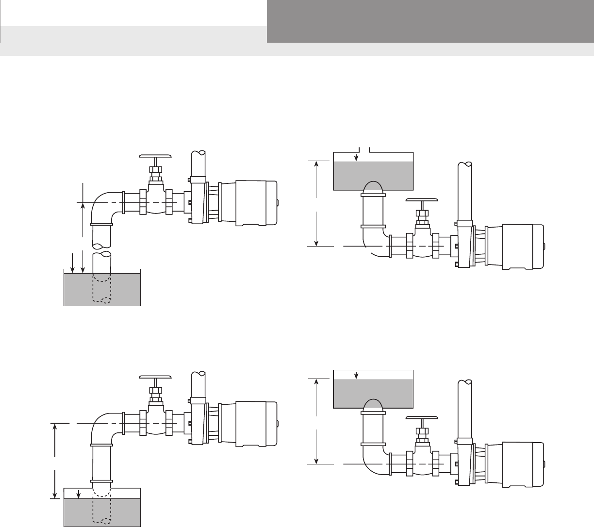
4a SUCTION SUPPLY OPEN TO ATMOSPHERE
– with Suction Lift
4b SUCTION SUPPLY OPEN TO ATMOSPHERE
– with Suction Head
4c CLOSED SUCTION SUPPLY
– with Suction Lift
4d CLOSED SUCTION SUPPLY
– with Suction Head
NPSHA=PB–(VP + LS + hf)
NPSHA=PB + LH–(VP + hf)
NPSHA =
p
– (LS+VP + hf)
NPSHA =
p
+ LH–(VP + hf)
p
LS
C
L
LS
C
L
PB
LH
C
L
PB
LH
C
L
PB = Barometric pressure, in feet absolute.
VP = Vapor pressure of the liquid at maximum pumping temperature, in feet absolute (see next page).
p
= Pressure on surface of liquid in closed suction tank, in feet absolute.
LS = Maximum static suction lift in feet.
LH = Minimum static suction head in feet.
h
f
= Friction loss in feet in suction pipe at required capacity.
Note: See page 23, atmospheric pressure chart.
p
CENTRIFUGAL PUMP FUNDAMENTALS
PAGE 12
Residential Water Systems
Goulds Water Technology,
Bell & Gossett, Red Jacket Series, CentriPro
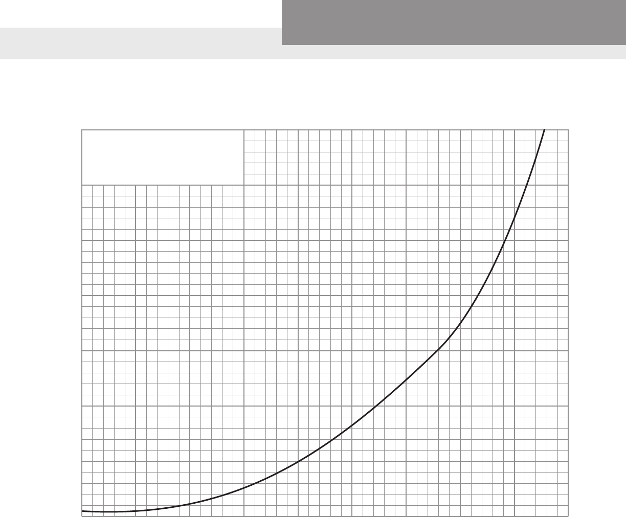
VAPOR PRESSURE OF WATER
5
10
20
25
30
35
40 100 120 140 160 180 200 220
Water Temperature ºF.
Vapor Pressure in Feet of Water
60 80
15
Deduct Vapor Pressure in
Feet of Water From the
Maximum Allowable Suction
Head at Sea Level.
CENTRIFUGAL PUMP FUNDAMENTALS

PAGE 13
Residential Water Systems
Goulds Water Technology,
Bell & Gossett, Red Jacket Series, CentriPro
NEMA CONTROL PANEL ENCLOSURES
Enclosure Rating Explanation
NEMA1 Topreventaccidentalcontactwithenclosedapparatus.Suitableforapplicationindoors
GeneralPurpose wherenotexposedtounusualserviceconditions.
NEMA2 Topreventaccidentalcontact,andinaddition,toexcludefallingmoistureordirt.
Driptight
NEMA3 Protectionagainstspeciedweatherhazards.Suitableforuseoutdoors.
Weatherproof
(Weatherproof Resistant)
NEMA3R Protectsagainstentranceofwaterfromabeatingrain.Suitableforgeneraloutdoor
Raintight application not requiring sleetproof.
NEMA4 Designedtoexcludewaterappliedinformofhosestream.Toprotectagainststreamof
Watertight waterduringcleaningoperations,etc.
NEMA4X Designedtoexcludewaterappliedinformofhosestream.Toprotectagainststreamof
Watertight & Corrosion Resistant
waterduringcleaningoperations,etc.CorrosionResistant.
NEMA5 Constructedsothatdustwillnotenterenclosedcase.BeingreplacedinsomeDustTight
Dusttight equipmentbyNEMA12.
NEMA6 Intendedtopermitenclosedapparatustobeoperatedsuccessfullywhentemporarily
Watertight,Dusttight submergedinwater.
NEMA7 DesignedtomeetapplicationrequirementsofNationalElectricalCodeforClass1,
HazardousLocations HazardousLocations(explosiveatmospheres).Circuitinterruptionoccursinair.
Class I
NEMA8 IdenticaltoNEMA7above,excepttheapparatusisimmersedinoil.
HazardousLocations
A,B,CorD
Class II – Oil Immersed
NEMA9 DesignedtomeetapplicationrequirementsofNationalElectricalCodeforClassII
ClassII–HazardousLocations HazardousLocations(combustibledusts,etc.).E,FandG.
NEMA10 MeetsrequirementsofU.S.BureauofMines.Suitableforuseincoalmines.
BureauofMines
Permissible
NEMA11 Providesoilimmersionofapparatussuchthatitissuitableforapplicationwhere
Dripproof equipment is subject to acid or other corrosive fumes.
Corrosion Resistant
NEMA12 Foruseinthoseindustrieswhereitisdesiredtoexcludedust,lint,bersandyings,or
Driptight,Dusttight oilorIndustrialcoolantseepage.
ELECTRICAL DATA
PAGE 14
Residential Water Systems
Goulds Water Technology,
Bell & Gossett, Red Jacket Series, CentriPro
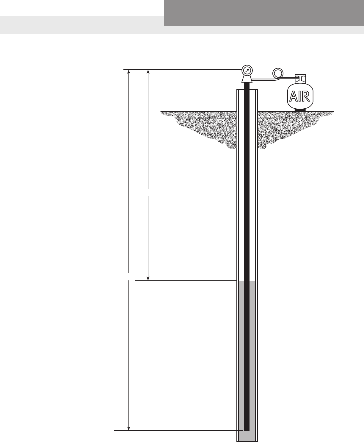
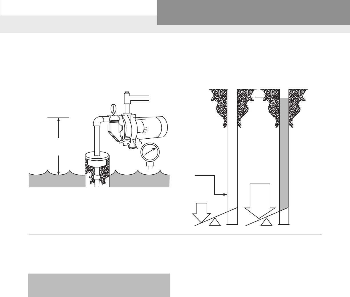
Install 1⁄8" or ¼" tubing long
enough to be 10' to 15' below
low water level. Measure the
tubing length as it is lowered
into the well.
Once the tubing is xed in a
stationary position at the top,
connect an air line and pres-
sure gauge. Add air to the tub-
ing until the pressure gauge
reaches a point that it doesn't
read any higher. Take a gauge
reading at this point.
A. Depth to water
(to be determined).
B. Total length of air line
(in feet).
C. Water pressure on air
tubing. Gauge reads in
pounds. Convert to feet by
multiplying by 2.31.
Example:
If the air tube is 100' long,
and the gauge reads 20 lbs.
20 lbs. x 2.31 = 46.2 ft.
Length of tube = 100 ft.
minus 46.2 ft. = 53.8 ft.
Depth to water (A) would be
53.8 ft.
A
B
DETERMINING WATER LEVEL
PAGE 15
Residential Water Systems
Goulds Water Technology,
Bell & Gossett, Red Jacket Series, CentriPro
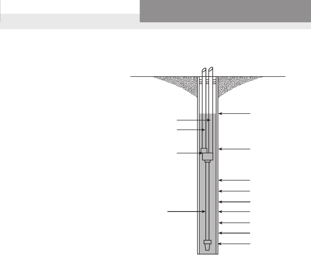
Pipe below the jet, or “tail pipe” as it is
commonly known, is used when you
have a weak deep well. Under normal
conditions, the jet assembly with the
foot valve attached is lowered into the
well. You receive your rated capacity at
the level you locate the jet assembly. On
a weak well, as the water level lowers
to the level of the foot valve (attached
to the bottom of the jet assembly), air
enters the system. By adding 34' of tail
pipe below the jet assembly with the foot
valve attached to the bottom of the 34'
length of pipe, it will not be possible to
pull the well down and allow air to enter
the system. The drawing indicates the
approximate percentage of rated capacity
you will receive with tail pipe.
Using a tail pipe, the pump delivery
remains at 100% at sea level of the rated
capacity down to the jet assembly level. If
water level falls below that, ow decreases
in proportion to drawdown as shown
in the illustration. When pump delivery
equals well inow, the water level remains
constant until the pump shuts off.
This rule can also be used when
determining suction pipe length on
shallow well systems.
HOW TO USE TAIL PIPE ON DEEP WELL JET PUMPS
DRIVEPIPE
SUCTIONPIPE
JETASSEMBLY
TAILPIPE
34FT.WILLPREVENT
BREAKINGSUCTION
STATICLEVEL
100%
33.9'MAXIMUM
DRAWDOWN0%
10'PIPE80%
15'PIPE70%
20'PIPE57%
25'PIPE40%
28'PIPE25%
29'PIPE17%
TAIL PIPE
PAGE 16
Residential Water Systems
Goulds Water Technology,
Bell & Gossett, Red Jacket Series, CentriPro
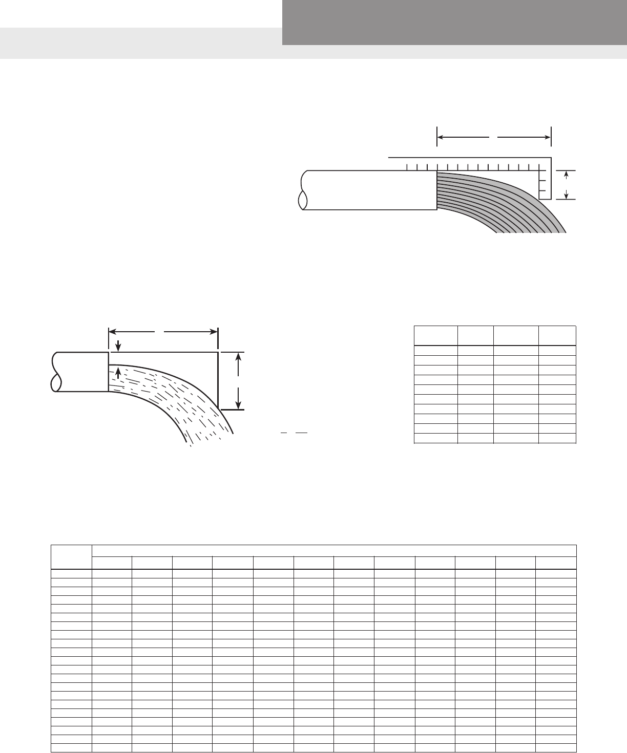
An L-shaped measuring square can be used to
estimate ow capacity, using the chart below. As
shown in illustration, place 4" side of square so that
it hangs down and touches the water. The horizontal
distance shown “A” is located in the rst column of
the chart and you read across to the pipe diameter
(ID) to nd the gallons per minute discharge rate.
Example: A is 8" from a 4" ID pipe
= a discharge rate of 166 GPM.
FULL PIPE FLOW – CALCULATION OF DISCHARGE RATE USING HORIZONTAL OPEN DISCHARGE FORMULA
Flow (GPM) = A x D x 1.093 x F
A = Area of pipe in square inches
D = Horizontal distance in inches
F = Effective area factor from chart
Area of pipe equals inside Dia.2 x 0.7854
Example: Pipeinsidediameter=10in.
D = 20 in.
F=2½in.
A = 10 x 10 x 0.7854 = 78.54 square in.
R% = F
=2½ = 25%
D 10
F = 0.805
Flow=78.54x20x1.039x0.805=1314GPM
PIPE NOT RUNNING FULL – CALCULATION OF DISCHARGE RATE USING AREA FACTOR METHOD
Flow From Horizontal Pipe (Not Full)
Ratio Eff. Area Ratio Eff. Area
F/D = R % Factor F F/D = R % Factor F
5 0.981 55 0.436
10 0.948 60 0.373
15 0.905 65 0.312
20 0.858 70 0.253
25 0.805 75 0.195
30 0.747 80 0.142
35 0.688 85 0.095
40 0.627 90 0.052
45 0.564 95 0.019
50 0.500 100 0.000
DISCHARGE RATE IN GALLONS PER MINUTE/NOMINAL PIPE SIZE (ID)
A
4"
F
D
12"
DETERMINING FLOW RATES
Horizontal Pipe Diameter
Dist. (A) 1" 1¼" 1½" 2" 2½" 3" 4" 5" 6" 8" 10" 12"
Inches
4 5.7 9.8 13.3 22.0 31.3 48.5 83.5
5 7.1 12.2 16.6 27.5 39.0 61.0 104 163
6 8.5 14.7 20.0 33.0 47.0 73.0 125 195 285
7 10.0 17.1 23.2 38.5 55.0 85.0 146 228 334 380
8 11.3 19.6 26.5 44.0 62.5 97.5 166 260 380 665 1060
9 12.8 22.0 29.8 49.5 70.0 110 187 293 430 750 1190 1660
10 14.2 24.5 33.2 55.5 78.2 122 208 326 476 830 1330 1850
11 15.6 27.0 36.5 60.5 86.0 134 229 360 525 915 1460 2100
12 17.0 29.0 40.0 66.0 94.0 146 250 390 570 1000 1600 2220
13 18.5 31.5 43.0 71.5 102 158 270 425 620 1080 1730 2400
14 20.0 34.0 46.5 77.0 109 170 292 456 670 1160 1860 2590
15 21.3 36.3 50.0 82.5 117 183 312 490 710 1250 2000 2780
16 22.7 39.0 53.0 88.0 125 196 334 520 760 1330 2120 2960
17 41.5 56.5 93.0 133 207 355 550 810 1410 2260 3140
18 60.0 99.0 144 220 375 590 860 1500 2390 3330
19 110 148 232 395 620 910 1580 2520 3500
20 156 244 415 650 950 1660 2660 3700
21 256 435 685 1000 1750 2800
22 460 720 1050 1830 2920
23 750 1100 1910 3060
24 1140 2000 3200

PAGE 17
Residential Water Systems
Goulds Water Technology,
Bell & Gossett, Red Jacket Series, CentriPro
THEORETICAL DISCHARGE OF NOZZLES IN U.S. GALLONS PER MINUTE
Velocity of
Head Discharge Diameter of Nozzle in Inches
Feet
Pounds Feet Per Second 1⁄16 1⁄8 3⁄16 1⁄4 3⁄8 1⁄2 5⁄8 3⁄4 7⁄8
10 23.1 38.6 0.37 1.48 3.32 5.91 13.3 23.6 36.9 53.1 72.4
15 34.6 47.25 0.45 1.81 4.06 7.24 16.3 28.9 45.2 65.0 88.5
20 46.2 54.55 0.52 2.09 4.69 8.35 18.8 33.4 52.2 75.1 102
25 57.7 61.0 0.58 2.34 5.25 9.34 21.0 37.3 58.3 84.0 114
30 69.3 66.85 0.64 2.56 5.75 10.2 23.0 40.9 63.9 92.0 125
35 80.8 72.2 0.69 2.77 6.21 11.1 24.8 44.2 69.0 99.5 135
40 92.4 77.2 0.74 2.96 6.64 11.8 26.6 47.3 73.8 106 145
45 103.9 81.8 0.78 3.13 7.03 12.5 28.2 50.1 78.2 113 153
50 115.5 86.25 0.83 3.30 7.41 13.2 29.7 52.8 82.5 119 162
55 127.0 90.4 0.87 3.46 7.77 13.8 31.1 55.3 86.4 125 169
60 138.6 94.5 0.90 3.62 8.12 14.5 32.5 57.8 90.4 130 177
65 150.1 98.3 0.94 3.77 8.45 15.1 33.8 60.2 94.0 136 184
70 161.7 102.1 0.98 3.91 8.78 15.7 35.2 62.5 97.7 141 191
75 173.2 105.7 1.01 4.05 9.08 16.2 36.4 64.7 101 146 198
80 184.8 109.1 1.05 4.18 9.39 16.7 37.6 66.8 104 150 205
85 196.3 112.5 1.08 4.31 9.67 17.3 38.8 68.9 108 155 211
90 207.9 115.8 1.11 4.43 9.95 17.7 39.9 70.8 111 160 217
95 219.4 119.0 1.14 4.56 10.2 18.2 41.0 72.8 114 164 223
100 230.9 122.0 1.17 4.67 10.5 18.7 42.1 74.7 117 168 229
105 242.4 125.0 1.20 4.79 10.8 19.2 43.1 76.5 120 172 234
110 254.0 128.0 1.23 4.90 11.0 19.6 44.1 78.4 122 176 240
115 265.5 130.9 1.25 5.01 11.2 20.0 45.1 80.1 125 180 245
120 277.1 133.7 1.28 5.12 11.5 20.5 46.0 81.8 128 184 251
125 288.6 136.4 1.31 5.22 11.7 20.9 47.0 83.5 130 188 256
130 300.2 139.1 1.33 5.33 12.0 21.3 48.0 85.2 133 192 261
135 311.7 141.8 1.36 5.43 12.2 21.7 48.9 86.7 136 195 266
140 323.3 144.3 1.38 5.53 12.4 22.1 49.8 88.4 138 199 271
145 334.8 146.9 1.41 5.62 12.6 22.5 50.6 89.9 140 202 275
150 346.4 149.5 1.43 5.72 12.9 22.9 51.5 91.5 143 206 280
175 404.1 161.4 1.55 6.18 13.9 24.7 55.6 98.8 154 222 302
200 461.9 172.6 1.65 6.61 14.8 26.4 59.5 106 165 238 323
Note:
Theactualquantitieswillvaryfromthesegures,theamountofvariationdependingupontheshapeofnozzleandsizeofpipeatthepointwherethepressureisdetermined.With
smoothtapernozzlestheactualdischargeisabout94percentoftheguresgiveninthetables.
DETERMINING FLOW RATES

PAGE 18
Residential Water Systems
Goulds Water Technology,
Bell & Gossett, Red Jacket Series, CentriPro
THEORETICAL DISCHARGE OF NOZZLES IN U.S. GALLONS PER MINUTE (continued)
Velocity of
Head Discharge Diameter of Nozzle in Inches
Feet
Pounds Feet Per Second 1 11⁄8 1
1⁄4 1
3⁄8 1
1⁄2 1
3⁄4 2 2
1⁄4 2
1⁄2
10 23.1 38.6 94.5 120 148 179 213 289 378 479 591
15 34.6 47.25 116 147 181 219 260 354 463 585 723
20 46.2 54.55 134 169 209 253 301 409 535 676 835
25 57.7 61.0 149 189 234 283 336 458 598 756 934
30 69.3 66.85 164 207 256 309 368 501 655 828 1023
35 80.8 72.2 177 224 277 334 398 541 708 895 1106
40 92.4 77.2 188 239 296 357 425 578 756 957 1182
45 103.9 81.8 200 253 313 379 451 613 801 1015 1252
50 115.5 86.25 211 267 330 399 475 647 845 1070 1320
55 127.0 90.4 221 280 346 418 498 678 886 1121 1385
60 138.6 94.5 231 293 362 438 521 708 926 1172 1447
65 150.1 98.3 241 305 376 455 542 737 964 1220 1506
70 161.7 102.1 250 317 391 473 563 765 1001 1267 1565
75 173.2 105.7 259 327 404 489 582 792 1037 1310 1619
80 184.8 109.1 267 338 418 505 602 818 1070 1354 1672
85 196.3 112.5 276 349 431 521 620 844 1103 1395 1723
90 207.9 115.8 284 359 443 536 638 868 1136 1436 1773
95 219.4 119.0 292 369 456 551 656 892 1168 1476 1824
100 230.9 122.0 299 378 467 565 672 915 1196 1512 1870
105 242.4 125.0 306 388 479 579 689 937 1226 1550 1916
110 254.0 128.0 314 397 490 593 705 960 1255 1588 1961
115 265.5 130.9 320 406 501 606 720 980 1282 1621 2005
120 277.1 133.7 327 414 512 619 736 1002 1310 1659 2050
125 288.6 136.4 334 423 522 632 751 1022 1338 1690 2090
130 300.2 139.1 341 432 533 645 767 1043 1365 1726 2132
135 311.7 141.8 347 439 543 656 780 1063 1390 1759 2173
140 323.3 144.3 354 448 553 668 795 1082 1415 1790 2212
145 334.8 146.9 360 455 562 680 809 1100 1440 1820 2250
150 346.4 149.5 366 463 572 692 824 1120 1466 1853 2290
175 404.1 161.4 395 500 618 747 890 1210 1582 2000 2473
200 461.9 172.6 423 535 660 790 950 1294 1691 2140 2645
Note:
Theactualquantitieswillvaryfromthesegures,theamountofvariationdependingupontheshapeofnozzleandsizeofpipeatthepointwherethepressureisdetermined.With
smoothtapernozzlestheactualdischargeisabout94percentoftheguresgiveninthetables.
DETERMINING FLOW RATES
PAGE 19
Residential Water Systems
Goulds Water Technology,
Bell & Gossett, Red Jacket Series, CentriPro
CALCULATING SUCTION LIFT
Suction lift is measured with a vacuum gauge. The gauge can be
calibrated in feet suction lift or inches vacuum.
14.7 lbs.
x 2.31 ft.
33.9 ft.
1 lb.
B. C.
2.31 ft.
14.7 lbs.
A. 1 inch vacuum equals 1.13
feet suction lift.
A reading of 20" on a vacuum gauge placed on the suction side of the
pumpwouldtellyouthatyouhadavacuumorsuctionliftof22.6feet.
20" x 1.13' = 22.6 feet
C. Atmospheric pressure of 14.7 x 2.31 =
33.9 feet which is the maximum suction lift at sea level.
Vacuum
Gauge
22.6'
VerticalLift
PlusFriction
20"
A.
A vacuum gauge indicates total suction lift (vertical lift + friction loss
=totallift)ininchesofmercury.1"onthegauge=1.13ft.oftotal
suction lift (based on pump located at sea level).
RULE OF THUMB
Practicalsuctionliftatsealevelis25ft.Deduct1ft.of
suction lift for each 1000 ft. of elevation above sea level.
Shallow Well System
Install vacuum gauge in shallow well adapter. When pump is run-
ning,thegaugewillshownovacuumiftheendofsuctionpipeisnot
submergedorthereisasuctionleak.Ifthegaugeshowsaveryhigh
vacuum(22inchesormore),thisindicatesthattheendofsuctionpipe
isburiedinmud,thefootvalveorcheckvalveisstuckclosedorthe
suctionliftexceedscapabilityofpump.
High Vacuum (22 inches or more)
• Suction pipe end buried in mud
• Foot valve or check valve stuck closed
•Suctionliftexceedscapabilityofthepump
Low Vacuum (or 0 vacuum)
• Suction pipe not submerged
• Suction leak
TERMS AND USABLE FORMULAS

PAGE 20
Residential Water Systems
Goulds Water Technology,
Bell & Gossett, Red Jacket Series, CentriPro
BASIC FORMULAS AND SYMBOLS
Theterm“head”byitselfis
rather misleading. It is
commonlytakentomeanthe
difference in elevation
between the suction level and
the discharge level of the liquid
being pumped. Although this
ispartiallycorrect,itdoesnot
include all of the conditions that
should be included to give an
accurate description.
■ Friction Head:
The pressure expressed in lbs./
sq. in. or feet of liquid needed to
overcome the resistance to the
owinthepipeandttings.
■ Suction Lift: Exists when the
sourceofsupplyisbelowthe
center line of the pump.
■ Suction Head: Exists when
thesourceofsupplyisabovethe
center line of the pump.
■ Static Suction Lift:
The vertical distance from
the center line of the pump
down to the free level of the
liquid source.
■ Static Suction Head:
The vertical distance from the
center line of the pump up to the
free level of the liquid source.
■ Static Discharge Head: The
vertical elevation from the center
line of the pump to the point of
free discharge.
■ Dynamic Suction Lift:
Includesstaticsuctionlift,fric-
tionheadlossandvelocityhead.
■ Dynamic Suction Head:
Includes static suction head
minus friction head minus veloc-
ityhead.
■ Dynamic Discharge Head:
Includes static discharge head
plusfrictionheadplusvelocity
head.
■ Total Dynamic Head:
Includesthedynamicdischarge
headplusdynamicsuctionliftor
minusdynamicsuctionhead.
■ Velocity Head: The head
needed to accelerate the liquid.
Knowingthevelocityoftheliq-
uid,thevelocityheadlosscanbe
calculatedbyasimpleformula
Head=V2/2g in which g is accel-
erationduetogravityor32.16
ft./sec.Althoughthevelocity
headlossisafactoringuring
thedynamicheads,thevalueis
usuallysmallandinmostcases
negligible. See table.
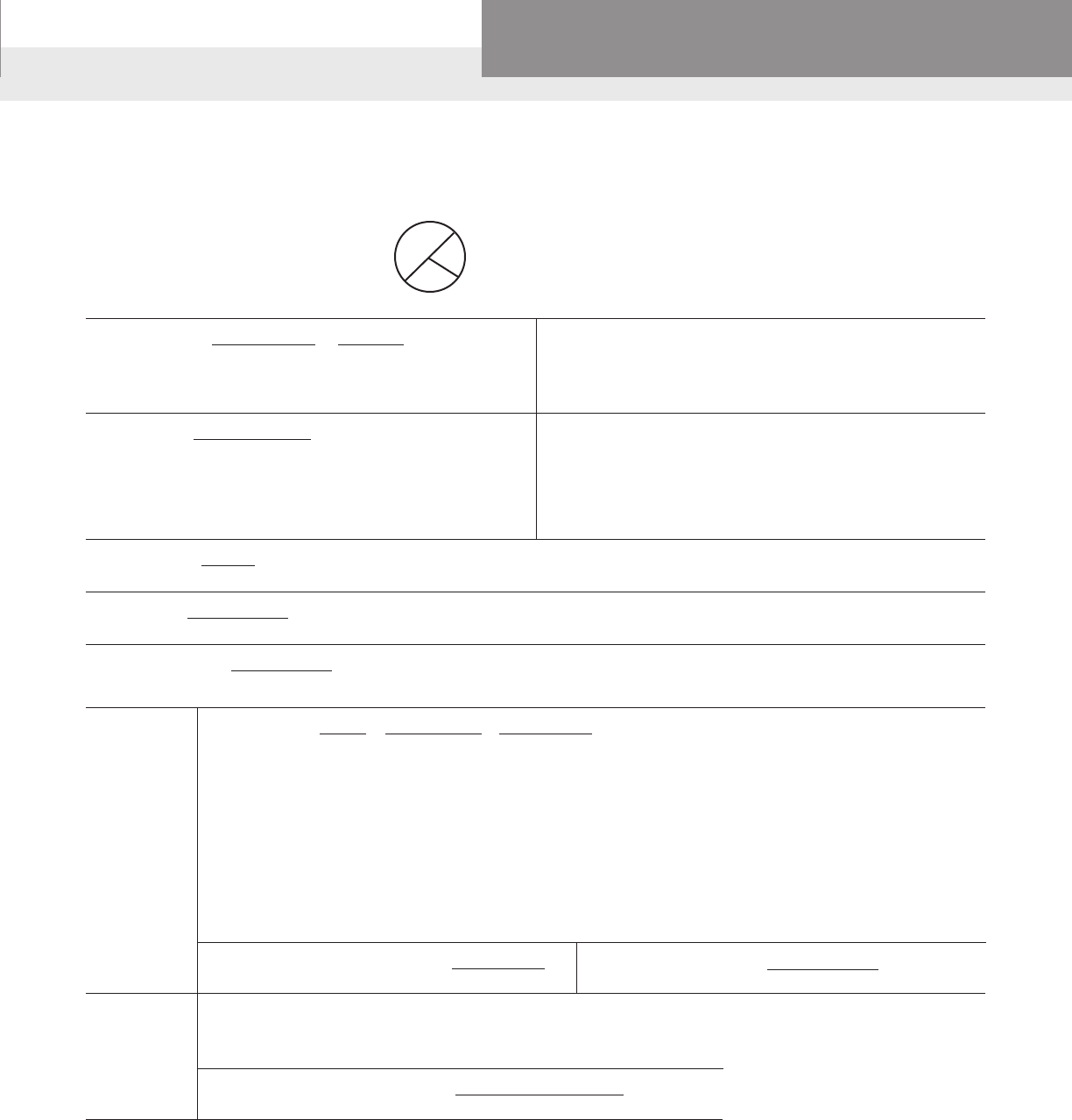
Formulas
GPM = Lb./Hr.
500xSp.Gr.
H= 2.31xpsi
Sp.Gr.
H= 1.134xIn.Hg.
Sp.Gr.
HV = V2 =0.155V2
2g
V = GPMx0.321 = GPMx0.409
A (I.D.)2
BHP = GPMxHxSp.Gr.
3960 x Eff.
Eff. = GPMxHxSp.Gr.
3960xBHP
NS = N√GPM
H
3/4
H = V2
2g
Symbols
GPM = gallons per minute
Lb. = pounds
Hr. = hour
Sp. Gr. = specicgravity
H = head in feet
psi = pounds per square inch
In. Hg. = inchesofmercury
hv = velocityheadinfeet
V = velocityinfeetpersecond
g = 32.16 ft./sec.2
(accelerationofgravity)
A = area in square inches (πr2)
(for a circle or pipe)
ID = inside diameter in inches
BHP = brake horsepower
Eff. = pumpefciency
expressed as a decimal
NS = specicspeed
N = speed in revolutions
per minute
D = impeller in inches
Approximate Cost of Operating Electric Motors
*Average kilowatts input *Av. kw input or cost
Motor or cost based on 1 cent Motor per hr. based on
HP per kilowatt hour HP 1 cent per kw hour
1 Phase 3 Phase 3 Phase
1⁄3 .408 20 16.9
1⁄2 .535 .520 25 20.8
3⁄4 .760 .768 30 26.0
1 1.00 .960 40 33.2
11⁄2 1.50 1.41 50 41.3
2 2.00 1.82 60 49.5
3 2.95 2.70 75 61.5
5 4.65 4.50 100 81.5
71⁄2 6.90 6.75 125 102
10 9.30 9.00 150 122
200 162
TERMS AND USABLE FORMULAS
PAGE 21
Residential Water Systems
Goulds Water Technology,
Bell & Gossett, Red Jacket Series, CentriPro
BASIC FORMULAS AND SYMBOLS
Water Horsepower = GPMx8.33xHead = GPMxHead
33000 3960
Temperature conversion
DEG.C = (DEG.F–32)x.555
DEG.F = (DEG.Cx1.8)+32
Area of a Circle
A = area; C = circumference.
A = πr2; π = 3.14
C = 2πr
r
CIRCLE
d
Where:
GPM = GallonsperMinute
8.33 = Poundsofwaterpergallon
33000 = Ft. Lbs. per minute in one horsepower
Head = Differenceinenergyheadinfeet(eldhead).
Laboratory BHP = HeadxGPMxSp.Gr.
3960 x Eff.
Field BHP = LaboratoryBHP+ShaftLoss
Total BHP = FieldBHP+ThrustBearingLoss
Where:
GPM = GallonsperMinute
Head = Lab.Head(includingcolumnloss)
Eff. = Lab.Eff.ofPumpBowls
Shaft Loss=HPlossduetomechanicalfrictionoflineshaftbearings
Thrust Bearing Loss=HPLossindriverthrustbearings
(See(1)belowunderMisc.)
Input Horsepower= TotalBPH
MotorEff.
Motor Eff. from Motor mfg. (as a decimal)
Field Efciency = WaterHorsepower
TotalBHP
Water HP as determined above
Total BHP as determined above
Overall Plant Efciency = WaterHorsepower
InputHorsepower
(See (2) below under Misc.)
Water HP as determined above
Input HP as determined above
Input Horsepower = BHP = 4.826xKxMxR = 1.732xExIxPF
Mot.Eff. T 746
BHP = BrakeHorsepowerasdeterminedabove
Mot. Eff. = RatedMotorEfciency
K = PowerCompanyMeterConstant
M = PowerCompanyMeterMultiplier,orRatioofCurrentandPotential
Transformers connected with meter
R = Revolutions of meter disk
T = Time in Sec. for R
E = VoltageperLegappliedtomotor
I = Amperes per Leg applied to motor
PF = Powerfactorofmotor
1.732 = Factor for 3-phase motors. This reduces to 1 for single phase motors
Electrical
Miscellaneous
Kilowatt input to Motor = .746xI.H.P. = 1.732xExIxPF
1000
KW-Hrs. Per 1000 Gallons of = HDinft.x0.00315
Cold Water Pumped Per Hour PumpEff.xMot.Eff.
(1) Thrust Bearing Loss=.0075HPper100RPMper1000lbs.thrust.*
(2) Overall Plant Efciency sometimes referred to as “Wire to Water” Efciency
*Thrust (in lbs.)=(thrustconstant(k)laboratoryhead)+(settinginfeetxshaftwt.perft.)
Note: Obtain thrust constant from curve sheets
Discharge Head (in feet of uid pumped) = DischargePressure(psi)x2.31
Sp.Gr.ofFluidPumped
D = diameter
r = radius
TERMS AND USABLE FORMULAS
PAGE 22
Residential Water Systems
Goulds Water Technology,
Bell & Gossett, Red Jacket Series, CentriPro
)
)
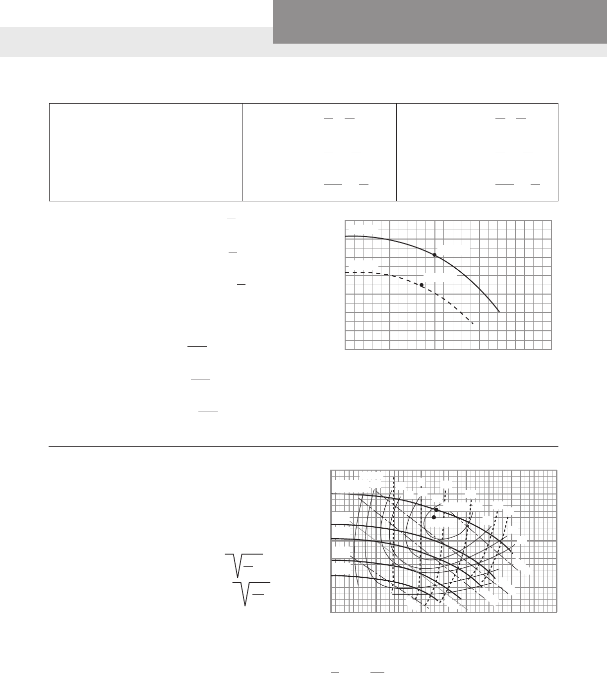
Toillustratetheuseoftheselaws,lets
look at a particular point (1) on a pump
curve(gure1).Thediameterofthe
impeller for this curve is 6 inches. We
willdeterminebytheuseoftheAfn-
ityLawswhathappenstothispointif
we trim the impeller to 5 inches.
From the 6 inch diameter curve we
obtain the following informa-
tion:
D1 = 6" Dia. D2 = 5" Dia.
Q1=200GPM Q2 = TBA
H1=100Ft. H2 = TBA
BHP1=7.5HP BHP2 = TBA
The equations 4 through 6 above
with speed (N) held constant will be
used and rearranged to solve for the
following:
Equation 4 Q2 = D2 x Q1
D1
Equation 5H
2 = D2
2
x H1
D1
Equation 6 BHP2 = D2
3
x BHP1
D1
(
(
The 6 inch information is put into the
formulas and the new 5 inch diameter point
iscalculated:
Q2 = 5"dia. x 200GPM =167 GPM
6" dia.
H2 = 5" dia. 2 x 100 Ft. = 69 Ft.
6" dia.
BHP2 = 5" dia. 3 x 7.5BHP = 4.3 BHP
6" dia.
(
(
The5inchdiameterHead/Capacityperformancepointcanbeplottedonthegraph
(gure1;point2).BytakingadditionalHead/Capacitypointsonthe6"diametercurve
lineandusingthisprocedure,anewHead/Capacitycurvelinecanbeproducedforthe5
inch diameter impeller.
This same procedure and equations 1 through 3 can be used when pump speed changes
and the impeller diameter remains constant.
Calculating impeller trim
using Afnity Laws:
Example:
Assumearequirementof225GPMat
160'ofHead(point2,gure2).Note
this point falls between 2 existing curve
lines with standard impeller diameters.
To determine the trimmed impeller
diametertomeetourrequirement,draw
a line from the required point (point 2)
perpendicular to an existing curve line
(point 1). Notice point 1 has an impeller
diameter (D1) of 63⁄4" and produces 230
GPM(Q1)at172'TDH(H1).
ApplyingAfnityLaw5tosolveforour
new impeller diameter (D2).
Point 1 (Known)
D1 = 63⁄4" Dia. Impeller
H
1 = 172'TDH
Q1 = 230GPM
Point 2 (Unknown)
D2 = Unknown
H
2 = 160'TDH
Q2 = 225GPM
Rearranging law 5 to solve for D2:
D2 = D1 x H2
H
1
D2 = 6.75 x 160
172
D2 = 6.55 = 69⁄16"
Determinethatthenewimpellerwillmeettherequiredcapacity:
Rearranging law 4 to solve for Q2:
Q2 = D2 x Q1 = 6.55 x 230 = 223
D1 6.75
20
140
100
CAPACITY (Q)
TOTAL HEAD (H)
FIGURE 1
0
40
60
80
120
100
0 200 300 400 GPM
6” DIA.
5” DIA.
POINT 1
POINT 2
240
100
CAPACITY (Q)
FIGURE 2
0
40
80
160
120
0 200 300 400 GPM
200
50 150 250 350
57⁄8"
53⁄8"
45⁄8"
41⁄8"
POINT 2
POINT 1
73
73
70
15'
65
20'
60
65
60
12'
15 HP
10 HP
7.5 HP
5 HP
3 HP
63⁄4" DIA.
EFF. 40
50 8'
70
10'
)
)
The afnity laws express the mathematical relationship
between several variables involved in pump performance.
They apply to all types of centrifugal and axial ow
pumps. They are as follows:
Q = Capacity,GPM
H = TotalHead,Feet
BHP = BrakeHorsepower
N = PumpSpeed,RPM
D = Impeller Diameter (in.)
Use equations
1 through 3
when
speed
changes
and
impeller
diameter
remains
constant
Use equations
4 through 6
with
impeller
diameter
changes
and
speed
remains
constant
1. Q1 = N1
Q2 N2
2. H1 = N1
2
H
2 N2
3. BHP1 = N1
3
BHP2 N2
( )
)
4. Q1 = D1
Q2 D2
5. H1 = D1
2
H
2 D2
6. BHP1 = D1
3
BHP2 D2
( )
( )(
AFFINITY LAWS

PAGE 23
Residential Water Systems
Goulds Water Technology,
Bell & Gossett, Red Jacket Series, CentriPro
Decimal and Millimeter Equivalents of Fraction Atmospheric Pressure, Barometer Reading and
Boiling Point of Water at Various Altitudes
Head and Pressure Equivalents
Inches Inches
Fractions Decimals Millimeters Fractions Decimals Millimeters
1⁄64 .015625 .397 33⁄64 .515625 13.097
1⁄32 .03125 .794 17⁄32 .53125 13.494
3⁄64 .046875 1.191 35⁄64 .546875 13.891
1⁄16 .0625 1.588 9⁄16 .5625 14.288
5⁄64 .078125 1.984 37⁄64 .578125 14.684
3⁄32 .09375 2.381 19⁄32 .59375 15.081
7⁄64 .109375 2.778 39⁄64 .609375 15.487
1⁄8 .125 3.175 5⁄8 .625 15.875
9⁄64 .140625 3.572 41⁄64 .640625 16.272
5⁄32 .15625 3.969 21⁄32 .65625 16.669
11⁄64 .171875 4.366 43⁄64 .671875 17.066
3⁄16 .1875 4.763 11⁄16 .6875 17.463
13⁄64 .203125 5.159 45⁄64 .703125 17.859
7⁄32 .21875 5.556 23⁄32 .71875 18.256
15⁄64 .234375 5.953 47⁄64 .734375 18.653
1⁄4 .250 6.350 3⁄4 .750 19.050
17⁄64 .265625 6.747 49⁄64 .765625 19.447
9⁄32 .28125 7.144 25⁄32 .78125 19.844
19⁄64 .296875 7.541 51⁄64 .796875 20.241
5⁄16 .3125 7.938 13⁄16 .8125 20.638
21⁄64 .328125 8.334 53⁄64 .828125 21.034
11⁄32 .34375 8.731 27⁄32 .84375 21.431
23⁄64 .359375 9.128 55⁄64 .859375 21.828
3⁄8 .375 9.525 7⁄8 .875 22.225
25⁄64 .390625 9.922 57⁄64 .890625 22.622
13⁄32 .40625 10.319 29⁄32 .90625 23.019
27⁄64 .421875 10.716 59⁄64 .921875 23.416
7⁄16 .4375 11.113 15⁄16 .9375 23.813
29⁄64 .453125 11.509 61⁄64 .953125 24.209
15⁄32 .46875 11.906 31⁄32 .96875 24.606
31⁄64 .484375 12.303 63⁄64 .984375 25.003
1⁄2 .500 12.700 1 1.000 25.400
1. Feet Head of Water and Equivalent Pressures
To change head in feet to pressure in pounds, multiply by .434
Feet PSI Feet PSI Feet PSI Feet PSI
Head Head Head Head
1 .43 30 12.99 140 60.63 300 129.93
2 .87 40 17.32 150 64.96 325 140.75
3 1.30 50 21.65 160 69.29 350 151.58
4 1.73 60 25.99 170 73.63 400 173.24
5 2.17 70 30.32 180 77.96 500 216.55
6 2.60 80 34.65 190 82.29 600 259.85
7 3.03 90 38.98 200 86.62 700 303.16
8 3.46 100 43.31 225 97.45 800 346.47
9 3.90 110 47.64 250 108.27 900 389.78
10 4.33 120 51.97 275 119.10 1000 433.09
20 8.66 130 56.30 - - - -
Altitude Barometer Reading Atmos. Press. Boiling Pt. of
Feet Meters In. Hg. Mm. Hg. Psia Ft. Water Water ºF
- 1000 - 304.8 31.0 788 15.2 35.2 213.8
- 500 - 152.4 30.5 775 15.0 34.6 212.9
0 0.0 29.9 760 14.7 33.9 212.0
+ 500 + 152.4 29.4 747 14.4 33.3 211.1
+ 1000 304.8 28.9 734 14.2 32.8 210.2
1500 457.2 28.3 719 13.9 32.1 209.3
2000 609.6 27.8 706 13.7 31.5 208.4
2500 762.0 27.3 694 13.4 31.0 207.4
3000 914.4 26.8 681 13.2 30.4 206.5
3500 1066.8 26.3 668 12.9 29.8 205.6
4000 1219.2 25.8 655 12.7 29.2 204.7
4500 1371.6 25.4 645 12.4 28.8 203.8
5000 1524.0 24.9 633 12.2 28.2 202.9
5500 1676.4 24.4 620 12.0 27.6 201.9
6000 1828.8 24.0 610 11.8 27.2 201.0
6500 1981.2 23.5 597 11.5 26.7 200.1
7000 2133.6 23.1 587 11.3 26.2 199.2
7500 2286.0 22.7 577 11.1 25.7 198.3
8000 2438.4 22.2 564 10.9 25.2 197.4
8500 2590.8 21.8 554 10.7 24.7 196.5
9000 2743.2 21.4 544 10.5 24.3 195.5
9500 2895.6 21.0 533 10.3 23.8 194.6
10000 3048.0 20.6 523 10.1 23.4 193.7
15000 4572.0 16.9 429 8.3 19.2 184.0
2. Pressure and Equivalent Feet Head of Water
To change pounds pressure to feet head, multiply by 2.3
PSI Feet PSI Feet PSI Feet PSI Feet
Head Head Head Head
1 2.31 20 46.18 120 277.07 225 519.51
2 4.62 25 57.72 125 288.62 250 577.24
3 6.93 30 69.27 130 300.16 275 643.03
4 9.24 40 92.36 140 323.25 300 692.69
5 11.54 50 115.45 150 346.34 325 750.41
6 13.85 60 138.54 160 369.43 350 808.13
7 16.16 70 161.63 170 392.52 375 865.89
8 18.47 80 184.72 180 415.61 400 922.58
9 20.78 90 207.81 190 438.90 500 1154.48
10 23.09 100 230.90 200 461.78 1000 2309.00
15 34.63 110 253.98 - - - -
CONVERSION CHARTS

PAGE 24
Residential Water Systems
Goulds Water Technology,
Bell & Gossett, Red Jacket Series, CentriPro
English measures – unless otherwise designated, are those used in
the United States.
Gallon – designates the U.S. gallon. To convert into the Imperial
gallon, multiply the U.S. gallon by 0.83267. Likewise, the word ton
designates a short ton, 2,000 pounds.
Properties of water – it freezes at 32ºF., and is at its maximum
density at 39.2ºF. In the multipliers using the properties of water,
calculations are based on water at 39.2ºF. in a vacuum, weighing
62.427 pounds per cubic foot, or 8.345 pounds per U.S. gallon.
Multiply By To Obtain
Acres 43,560 Squarefeet
Acres 4047 Square meters
Acres 1.562 x 10³ Square miles
Acres 4840 Squareyards
Atmospheres 76.0 Cms.ofmercury
Atmospheres 29.92 Inchesofmercury
Atmospheres 33.90 Feet of water
Atmospheres 10,332 Kgs./sq.meter
Atmospheres 14.70 Lbs./sq. inch
Atmospheres 1.058 Tons/sq. ft.
Barrels-Oil 42 Gallons-Oil
Barrels-Beer 31 Gallons-Beer
Barrels-Whiskey 45 Gallons-Whiskey
Barrels/Day-Oil 0.02917 Gallons/Min-Oil
Bagsorsacks-cement 94 Pounds-cement
Board feet 144 sq. in. x 1 in. Cubic inches
B.T.U./min. 12.96 Foot-lbs./sec.
B.T.U./min. 0.02356 Horsepower
B.T.U./min. 0.01757 Kilowatts
B.T.U./min. 17.57 Watts
Centimeters 0.3937 Inches
Centimeters 0.01 Meters
Centimeters 10 Millimeters
Cubic feet 2.832 x 10⁴ Cubic cms.
Cubic feet 1728 Cubic inches
Cubic feet 0.02832 Cubic meters
Cubicfeet 0.03704 Cubicyards
Cubicfeet 7.48052 Gallons
Cubic feet 28.32 Liters
Cubicfeet 59.84 Pints(liq.)
Cubic feet 29.92 Quarts (liq.)
Cubic feet/min. 472.0 Cubic cms./sec.
Cubicfeet/min. 0.1247 Gallons/sec.
Cubic feet/min. 0.4719 Liters/sec.
Cubic feet/min. 62.43 Lbs. of water/min.
Cubicfeet/sec. 0.646317 Millionsgals./day
Cubicfeet/sec. 448.831 Gallons/min.
Cubic inches 16.39 Cubic centimeters
Cubic inches 5.787 x 10⁻⁴ Cubic feet
Cubic inches 1.639 x 10⁻⁵ Cubic meters
Cubic inches 2.143 x 10⁻⁵ Cubicyards
Multiply By To Obtain
Cubic inches 4.329 x 10⁻³ Gallons
Cubic inches 1.639 x 10⁻² Liters
Cubicinches 0.03463 Pints(liq.)
Cubic inches 0.01732 Quarts (liq.)
Cubicyards 764,544.86 Cubiccentimeters
Cubicyards 27 Cubicfeet
Cubicyards 46,656 Cubicinches
Cubicyards 0.7646 Cubicmeters
Cubicyards 202.0 Gallons
Cubicyards 764.5 Liters
Cubicyards 1616 Pints(liq.)
Cubicyards 807.9 Quarts(liq.)
Cubicyards/min. 0.45 Cubicfeet/sec.
Cubicyards/min. 3.366 Gallons/sec.
Cubicyards/min. 12.74 Liters/sec.
Fathoms 6 Feet
Feet 30.48 Centimeters
Feet 12 Inches
Feet 0.3048 Meters
Feet 1/3 Yards
Feet of water 0.0295 Atmospheres
Feetofwater 0.8826 Inchesofmercury
Feet of water 304.8 Kgs./sq. meter
Feet of water 62.43 Lbs./Sq. ft.
Feet of water 0.4335 Lbs./sq. inch
Feet/min. 0.5080 Centimeters/sec.
Feet/min. 0.01667 Feet/sec.
Feet/min. 0.01829 Kilometers/hr.
Feet/min. 0.3048 Meters/min.
Feet/min. 0.01136 Miles/hr.
Feet/sec. 30.48 Centimeters/sec.
Feet/sec. 1.097 Kilometers/hr.
Feet/sec. 0.5924 Knots
Feet/sec. 18.29 Meters/min.
Feet/sec. 0.6818 Miles/hr.
Feet/sec. 0.01136 Miles/min.
Feet/sec./sec. 30.48 Cms./sec./sec.
Feet/sec./sec. 0.3048 Meters/sec./sec.
Foot-pounds 1.286 x 10³ BritishThermalUnits
Foot-pounds 5.050 x 10⁷ Horsepower-hrs.
Foot-pounds 3.240 x 10⁴ Kilogram-calories
CONVERSION CHARTS

PAGE 25
Residential Water Systems
Goulds Water Technology,
Bell & Gossett, Red Jacket Series, CentriPro
Multiply By To Obtain
Foot-pounds 0.1383 Kilogram-meters
Foot-pounds 3.766 x 10⁷ Kilowatt-hours
Gallons 3785 Cubiccentimeters
Gallons 0.1337 Cubicfeet
Gallons 231 Cubicinches
Gallons 3.785x10⁻³ Cubic meters
Gallons 4.951x10⁻³ Cubicyards
Gallons 3.785 Liters
Gallons 8 Pints(liq.)
Gallons 4 Quarts(liq.)
Gallons-Imperial 1.20095 U.S.gallons
Gallons-U.S. 0.83267 Imperialgallons
Gallonswater 8.345 Poundsofwater
Gallons/min. 2.228x10⁻³ Cubic feet/sec.
Gallons/min. 0.06308 Liters/sec.
Gallons/min. 8.0208 Cu.ft./hr.
Gallons/min. .2271 Meters3/hr.
Grains/U.S.gal. 17.118 Parts/million
Grains/U.S.gal. 142.86 Lbs./milliongal.
Grains/Imp.gal. 14.254 Parts/million
Grams 15.43 Grains
Grams .001 Kilograms
Grams 1000 Milligrams
Grams 0.03527 Ounces
Grams 2.205x10⁻³ Pounds
Horsepower 42.44 B.T.U./min.
Horsepower 33,000 Foot-lbs./min.
Horsepower 550 Foot-lbs./sec.
Horsepower 1.014 Horsepower(metric)
Horsepower 0.7457 Kilowatts
Horsepower 745.7 Watts
Horsepower(boiler) 33,493 B.T.U./hr.
Horsepower(boiler) 9.809 Kilowatts
Horsepower-hours 2546 B.T.U.
Horsepower-hours 1.98x10⁶ Foot-lbs.
Horsepower-hours 2.737x10⁵ Kilogram-meters
Horsepower-hours 0.7457 Kilowatt-hours
Inches 2.540 Centimeters
Inchesofmercury 0.03342 Atmospheres
Inchesofmercury 1.133 Feetofwater
Inchesofmercury 345.3 Kgs./sq.meter
Inchesofmercury 70.73 Lbs./sq.ft.
Inchesofmercury(32°F) 0.491 Lbs./sq.inch
Inches of water 0.002458 Atmospheres
Inchesofwater 0.07355 Inchesofmercury
Inches of water 25.40 Kgs./sq. meter
Inches of water 0.578 Ounces/sq. inch
Inches of water 5.202 Lbs. sq. foot
Inches of water 0.03613 Lbs./sq. inch
Kilograms 2.205 Lbs.
Multiply By To Obtain
Kilograms 1.102 x 10⁻³ Tons (short)
Kilograms 103 Grams
Kiloliters 103 Liters
Kilometers 105 Centimeters
Kilometers 3281 Feet
Kilometers 103 Meters
Kilometers 0.6214 Miles
Kilometers 1094 Yards
Kilometers/hr. 27.78 Centimeters/sec.
Kilometers/hr. 54.68 Feet/min.
Kilometers/hr. 0.9113 Feet/sec.
Kilometers/hr. .5399 Knots
Kilometers/hr. 16.67 Meters/min.
Kilowatts 56.907 B.T.U./min.
Kilowatts 4.425 x 10⁴ Foot-lbs./min.
Kilowatts 737.6 Foot-lbs./sec.
Kilowatts 1.341 Horsepower
Kilowatts 103 Watts
Kilowatt-hours 3414.4 B.T.U.
Kilowatt-hours 2.655 x 10⁶ Foot-lbs.
Kilowatt-hours 1.341 Horsepower-hrs.
Kilowatt-hours 3.671 x 10⁵ Kilogram-meters
Liters 103 Cubic centimeters
Liters 0.03531 Cubic feet
Liters 61.02 Cubic inches
Liters 10–3 Cubic meters
Liters 1.308 x 10⁻³ Cubicyards
Liters 0.2642 Gallons
Liters 2.113 Pints(liq.)
Liters 1.057 Quarts (liq.)
Liters/min. 5.886 x 10⁻⁴ Cubic ft./sec.
Liters/min. 4.403 x 10⁻³ Gals./sec.
Lumber Width (in.) x
Thickness (in.) Length (ft.) Board feet
12
Meters 100 Centimeters
Meters 3.281 Feet
Meters 39.37 inches
Meters 10–3 Kilometers
Meters 103 Millimeters
Meters 1.094 Yards
Miles 1.609x10⁵ Centimeters
Miles 5280 Feet
Miles 1.609 Kilometers
Miles 1760 Yards
Miles/hr. 44.70 Centimeters/sec.
Miles/hr. 88 Feet/min.
Miles/hr. 1.467 Feet/sec.
Miles/hr. 1.609 Kilometers/hr.
Miles/hr. 0.8689 Knots
CONVERSION CHARTS
PAGE 26
Residential Water Systems
Goulds Water Technology,
Bell & Gossett, Red Jacket Series, CentriPro
Multiply By To Obtain
Square kilometers 247.1 Acres
Square kilometers 10.76 x 10⁶ Square feet
Square kilometers 106 Square meters
Square kilometers 0.3861 Square miles
Square kilometers 1.196 x 10⁶ Squareyards
Square meters 2.471 x 10⁻⁴ Acres
Square meters 10.76 Square feet
Square meters 3.861 x 10⁻⁷ Square miles
Squaremeters 1.196 Squareyards
Square miles 640 Acres
Square miles 27.88 x 10⁶ Square feet
Square miles 2.590 Square kilometers
Square miles 3.098 x 10⁶ Squareyards
Squareyards 2.066x10⁻⁴ Acres
Squareyards 9 Squarefeet
Squareyards 0.8361 Squaremeters
Squareyards 3.228x10⁻⁷ Square miles
Temp (ºC)+273 1 Abs. temp. (ºC)
Temp. (ºC)+17.78 1.8 Temp. (ºF)
Temp. (ºF)+460 1 Abs. temp. (ºF)
Temp. (ºF)-32 5/9 Temp (ºC)
Tons (metric) 103 Kilograms
Tons(metric) 2205 Pounds
Tons(short) 2000 Pounds
Tons(short) 32,000 Ounces
Tons (short) 907.1843 Kilograms
Tons (short) 0.89287 Tons (long)
Tons (short) 0.90718 Tons (metric)
Tonsofwater/24hrs. 83.333 Poundswater/hr.
Tonsofwater/24hrs. 0.16643 Gallons/min.
Tons of water/24 hrs. 1.3349 Cu. ft./hr.
Watts 0.05686 B.T.U./min.
Watts 44.25 Foot-lbs./min.
Watts 0.7376 Foot-lbs./sec.
Watts 1.341 x 10⁻³ Horsepower
Watts 0.01434 Kg.-calories/min.
Watts 10–3 Kilowatts
Watt-hours 3.414 B.T.U.
Watt-hours 2655 Foot-lbs.
Watt-hours 1.341 x 10⁻³ Horsepower-hrs.
Watt-hours 0.8604 Kilogram-calories
Watt-hours 367.1 Kilogram-meters
Watt-hours 10–3 Kilowatt-hours
Yards 91.44 Centimeters
Yards 3 Feet
Yards 36 Inches
Yards 0.9144 Meters
Multiply By To Obtain
Miles/hr. 26.82 Meters/min.
Miles/min. 2682 Centimeters/sec.
Miles/min. 88 Feet/sec.
Miles/min. 1.609 Kilometers/min.
Miles/min. 60 Miles/hr.
Ounces 16 Drams
Ounces 437.5 Grains
Ounces 0.0625 Pounds
Ounces 28.3495 Grams
Ounces 2.835 x 10⁻⁵ Tons (metric)
Parts/million 0.0584 Grains/U.S.gal.
Parts/million 0.07015 Grains/Imp.gal.
Parts/million 8.345 Lbs./milliongal.
Pounds 16 Ounces
Pounds 256 Drams
Pounds 7000 Grains
Pounds 0.0005 Tons(short)
Pounds 453.5924 Grams
Poundsofwater 0.01602 Cubicfeet
Poundsofwater 27.68 Cubicinches
Poundsofwater 0.1198 Gallons
Poundsofwater/min. 2.670x10⁻⁴ Cubic ft./sec.
Pounds/cubicfoot 0.01602 Grams/cubiccm.
Pounds/cubicfoot 16.02 Kgs./cubicmeters
Pounds/cubicfoot 5.787x10⁻⁴ Lbs./cubic inch
Pounds/cubicinch 27.68 Grams/cubiccm.
Pounds/cubicinch 2.768x10⁴ Kgs./cubic meter
Pounds/cubicinch 1728 Lbs./cubicfoot
Pounds/foot 1.488 Kgs./meter
Pounds/inch 1152 Grams/cm.
Pounds/sq.foot 0.01602 Feetofwater
Pounds/sq.foot 4.882 Kgs./sq.meter
Pounds/sq.foot 6.944x10⁻³ Pounds/sq.inch
Pounds/sq.inch 0.06804 Atmospheres
PSI 2.307 Feetofwater
PSI 2.036 Inchesofmercury
PSI 703.1 Kgs./sq.meter
Quarts(dry) 67.20 Cubicinches
Quarts (liq.) 57.75 Cubic inches
Square feet 2.296 x 10⁻⁵ Acres
Square feet 929.0 Square centimeters
Square feet 144 Square inches
Square feet 0.09290 Square meters
Square feet 3.587 x 10⁻⁴ Square miles
Squarefeet 1/9 Squareyards
1 8.0208 Overowrate
sq. ft./gal./min. (ft./hr.)
Square inches 6.452 Square centimeters
Square inches 6.944 x 10⁻³ Square feet
Square inches 645.2 Square millimeters
CONVERSION CHARTS
PAGE 27
Residential Water Systems
Goulds Water Technology,
Bell & Gossett, Red Jacket Series, CentriPro
STORAGE OF WATER IN VARIOUS SIZE PIPES
Pipe Size Volume in Pipe Size Volume in
Gallons per Foot Gallons per Foot
1¼ .06 6 1.4
1½ .09 8 2.6
2 .16 10 4.07
3 .36 12 5.87
4 .652
MINIMUM FLOW TO MAINTAIN 2FT./SEC.
*SCOURING VELOCITY IN VARIOUS PIPES
Pipe Size Minimum GPM Pipe Size Minimum GPM
1¼ 9 6 180
1½ 13 8 325
2 21 10 500
3 46 12 700
4 80
*Failuretomaintainorexceedthisvelocitywillresultincloggedpipes.Basedon
schedule 40 nominal pipe.
STORAGE OF WATER IN VARIOUS SIZES OF WELLS
D2 = Gals.ofStorageperFoot
24.5
Where:D=Insidediameterofwellcasingininches
Examples:
2"Casing =.16Gals.perft.Storage 8"Casing =2.6Gals.perft.Storage
3"Casing =.36Gals.perft.Storage 10"Casing =4.07Gals.perft.Storage
4"Casing =.652Gals.perft.Storage 12"Casing =5.87Gals.perft.Storage
5"Casing =1.02Gals.perft.Storage 14"Casing =7.99Gals.perft.Storage
6"Casing =1.4Gals.perft.Storage 16"Casing =10.44Gals.perft.Storage
PIPE VOLUME AND VELOCITY
PAGE 28
Residential Water Systems
Goulds Water Technology,
Bell & Gossett, Red Jacket Series, CentriPro
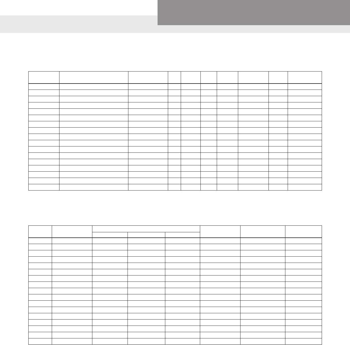
A.O. SMITH MOTOR DATA
ELECTRICAL COMPONENTS
GWT Where Used A.O. Smith HP Volts Phase Service Max. Load Watts Circuit
Number Factor Amps Breaker
J04853 J05,HB705 C48J2DB11C3HF ½ 115/230 1 1.6 10.8/5.4 880 25/15
J05853 JL07N,HSJ07,XSH07,HB C48K2DB11A4HH ¾ 115/230 1 1.5 14.8/7.4 1280 30/15
J06853 JL10N,HSJ10,SJ10,XSH10,HB C48L2DB11A4HH 1 115/230 1 1.4 16.2/8.1 1440 30/20
J07858 HSJ15,SJ15,HB,XSH15 C48M2DB11A1HH 1½ 115/230 1 1.3 20.0/10.0 1866 40/20
J08854 HSJ20,HSC20,XSH20 K48N2DB11A2HH 2 115/230 1 1.2 22.6/11.3 2100 25/15
② J09853 GT30,HSC30 _-196427 3 230 1 1.15 13.3 3280 30
② J04853L J5(S),GB C48A93A06 ½ 115/230 1 1.6 10.8/5.4 968 25/15
② J05853L J7(S),GB,GT07,(H)SJ07,HSC07 C48A94A06 ¾ 115/230 1 1.5 14.8/7.4 1336 30/15
② J06853L J10(S),GB,GT10,(H)SJ10,HSC10 C48A95A06 1 115/230 1 1.4 16.2/8.1 1592 30/20
② J07858L J15(S),GB,GT15,HSJ15,HSC15 C48M2DC11A1 1½ 115/230 1 1.3 21.4/10.7 1950 40/20
①② J08854L HSJ20,GB,GT20,HSC20 K48A34A06 2 230 1 1.2 12.9 2100 25
SFJ04853 JB05 S48A90A06 ½ 115/230 1 1.6 9.4/4.7 900 20/10
SFJ05853 JB07 C48A77A06 ¾ 115/230 1 1.5 13.6/6.8 1160 25/15
SFJ06853 JB10 C48A78A06 1 115/230 1 1.4 15.8/7.9 1400 30/20
② SFJ04860 JRS5,JRD5,JB05 C48C04A06 ½ 115/230 1 1.6 12.6/6.3 990 25/15
② SFJ05860 JRS7,JRD7,JB07 C48C05A06 ¾ 115/230 1 1.5 14.8/7.4 1200 30/15
② SFJ06860 JRS10,JRD10,JB10 C48C06A06 1 115/230 1 1.4 16.2/8.1 1400 30/20
①EffectiveJuly,1998,230Vonly.② Current production motor
GWT Motor A.O. Smith Motor Overload with Leads Run Capacitor Start Capacitor Switch⑤
Model Motor Model ④ Old Version ③ New Version T.I. Number and MFD MFD Rating
J04853 C48J2DB11C3HF 61424671 — MET38ABN 6108071:124/148 6290022
J05853 C48K2DB11A4HH 61424620 — CET63ABN 6108072:161/192 6290022
J06853 C48L2DB11A4HH 6142469 — CET52ABN 6108072:161/192 6290022
J07858 C48M2DB11A1HH 61424679 — CET38ABM 6108072:161/192 6290022
J08854 K48N2DB11A2HH N/A — BRT44ABM 6145294:25 6108071:124/148 6290022
J09853 _ - 196427-20 611106 22 61110636 BRB2938 628318314:55 61080711;36-43 6290022
J04853L C48A93A06 614246 98 62712143 MET39ABN-CL 6108071:124/148 6290022
J05853L C48A94A06 614246 20 62712138 CET63ABN 6108072:161/192 6290022
J06853L C48A95A06 614246 9 6271217 CET52ABN 6108072:161/192 6290022
J07858L C48C53A06 — 61112321 BRT45ABM 6108077:189/227 6290022
J08854L K48A34A06 616861 10 62711910 CET31ABN 628318308:30 61080733:64-77 6290022
SFJ04853 S48A90A06 6218631 — MEJ38ABN N/A 3945C91A01
SFJ05853 C48A77A06 6218634 — CET55ABN 6108072:161/192 3945C91A01
SFJ06853 C48A78A06 6218635 — CET49ABN 6108072:161/192 3945C91A01
SFJ04860 C48C04A06 614246 67 62712148 MET36ABN 6108072:161/192 6290022
SFJ05860 C48C05A06 614246 20 62712138 CET63ABN 6108072:161/192 6290022
SFJ06860 C48C06A06 614246 9 6271217 CET52ABN 6108072:161/192 6290022
③ These new overload part numbers are for use with the new plastic terminal board with the quick change voltage plug.
④ Usethissufxifyourmotorhastheoldstylebrownterminalboardwithoutquickchangevoltageplug.
⑤ 6290022replaces6142341,2,and6.
JET PUMP MOTOR DATA AND ELECTRICAL COMPONENTS
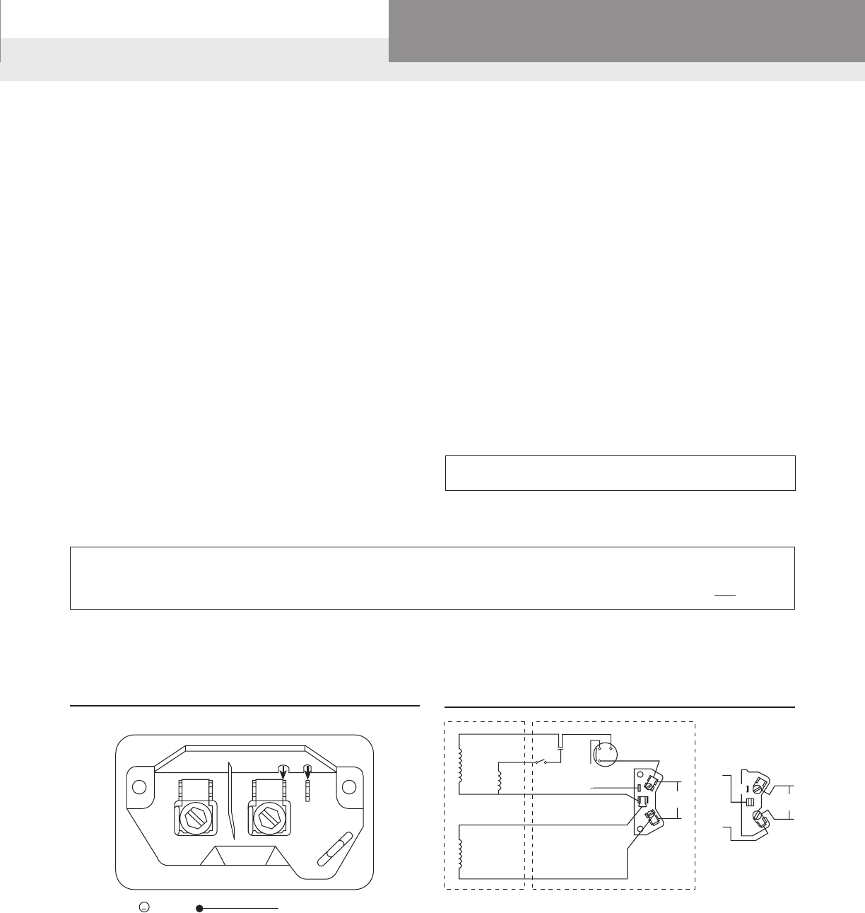
PAGE 29
Residential Water Systems
Goulds Water Technology,
Bell & Gossett, Red Jacket Series, CentriPro
TERMINAL BOARD AND VOLTAGE CHANGE PLUG
A change has been made to use
a new terminal board on the A.O.
Smith two compartment motor
models. This terminal board is
used on both dual voltage and
single voltage motors.
FEATURES
■ Voltage Plug: Dual voltage
motors use a voltage plug
that retains the terminals for
the Black and Black Tracer
leads.Tochangevoltage,lift
the black plug and align the
arrow with the desired volt-
age on terminal board. See
Figure 1 for an example of
the dual voltage connection
diagram.
■ Screws with ¼" drive: The
terminal screw accepts either
a ¼" nut driver or a slotted
screw driver.
■ Line Wire Connection: The
space under the screw will
accept#16,#14,#12,#10,or
#8 wire. The rib at the bottom
edge of the screw allows the
wire to be placed straight
into the space under the
screw. This rib retains the wire
under the head of the screw
andfor#12,#10,or#8wireit
isnotnecessarytowrapthe
wire around the screw.
■½HPwired115V,¾HPand
upwired230Vatfactory.
■ Quick Connect Terminals:
Each terminal has provision
for ¼" quick connect termi-
nals in addition to the screw.
■ Molded Plastic Material:
The terminal board is made
fromanextremelytough
white plastic material with
L1,L2,andAmarkings
molded into the board.
■ Lead Channel: A channel
adjacent to the conduit hole
directs wiring to the top of
the board.
■ Governor Guard: An
integral backplate prevents
leads from entering the area
around the governor.
■ Ground Guard: To
prevent the bare ground wire
from touching the “live” L2
terminal,thegroundwire
must be placed above this
guard.
115 V 230 V
L1 L2
A
FIGURE1
LINE
GRD Green(Ground)
Alignblackplugto115Vor230Varrow.
½HPwired115V,¾HPandupwired230V
atfactory.
CAPACITOR START INDUCTION RUN – SINGLE
SPEED (OLD STYLE – UP TO APRIL, 1999)
MAINMAIN
PHASE
YELLOW YELLOW
RED
BLACK
PURPLE
WHITE
RED
BLACK TRACER
230V
L2
L1
L2
L1
A
B
BLACK
TRACER
115V
L2
L1
A
B
BLACK
TO WIRE FOR 230 V:
BLACK TRACER TO B
BLACK TO A
TO WIRE FOR 115 V:
BLACK TRACER TO A
BLACK TO L1
WARNING:
DISCONNECT POWER SOURCE BEFORE CHECKING. DO NOT MAKE ANY CHANGES WITH POWER ON.
123
CAPACITOR START INDUCTION RUN – SINGLE
SPEED (NEW STYLE – AFTER APRIL, 1999)
“Black Tracer” is a black and white wire
VOLTAGE CHANGES ARE MADE INSIDE THE
MOTOR COVER NOT IN THE PRESSURE SWITCH.
JET PUMP MOTOR WIRING A.O. SMITH MOTORS

PAGE 30
Residential Water Systems
Goulds Water Technology,
Bell & Gossett, Red Jacket Series, CentriPro
115/230 VOLTAGE CONNECTIONS
115 Voltage 230 Voltage TO CHANGE MOTOR VOLTAGE:
Black—A Black—1 Models without a Switch
Wht./Blk.Tracer—1 Wht./Blk.Tracer—B 115V to 230V 230V to 115V
Line1—2 Line1—2 MoveWht./Blk.tracertoB MoveBlk.toA
Line2—A Line2—A MoveBlk.to1 MoveWht./Blk.tracerto1
(Blue—3) (Blue—3) Models with Voltage Change Switch
•Movetoggleswitchbetween115Vor230V.
LINE 1
1
2
B
WHT/BLK
TRACER
LINE 2
BLACK
LINE 1
1
2
A
WHT/BLK
TRACER
B
BLACK
CONNECTIONS
115 VOLTAGE 230 VOLTAGE
3 3
A
LINE 2
Motorisnon-reversibleCCWrotationshaftend.
Supplyconnections,usewiressizedonthebasisof60ºCampacityandratedminimum90ºC.
A – has 2 male
connectors and
1 screw connector
2 – has 2 male
connectors and
1 screw connector
B–isadummyterminal
used to hold the Wht./
Blk.Tracerfor230V
wiring
EMERSON MOTOR WIRING
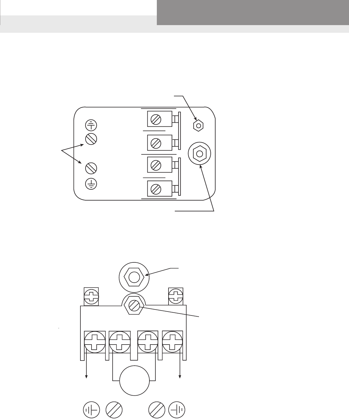
PAGE 31
Residential Water Systems
Goulds Water Technology,
Bell & Gossett, Red Jacket Series, CentriPro
CENTRIPRO AND SQUARE "D" SWITCHES
Grounding
Provisions
#8-32 screws
Range: adjust
for cut-in point
Differential: adjust
for cut-out point
ADJUSTMENT
Line
L1
Load
Load
Line
L2
LINE LOAD LOAD LINE
MOTOR
L1 L2
MAIN SPRING ADJUSTMENT
Turn clockwise to increase both cut-out
and cut-in pressure. (2 PSI/turn)
DIFFERENTIAL
ADJUSTMENT
Turn clockwise to increase
cut-out pressure without
affecting cut-in. (3 PSI/turn)
HUBBELL (FURNAS) PRO CONTROL SWITCH
Adjust in proper sequence:
1.CUT-IN:Turnnutdownforhighercut-in
pressure,orupforlowercut-in.
2.CUT-OUT:Turnnutdownforhighercut-
outpressure,orupforlowercut-out.
CAUTION:TOAVOIDDAMAGE,DONOT
EXCEEDTHEMAXIMUMALLOWABLE
SYSTEMPRESSURE.CHECKSWITCH
OPERATIONAFTERRESETTING.
PRESSURE SWITCH WIRING AND ADJUSTMENTS
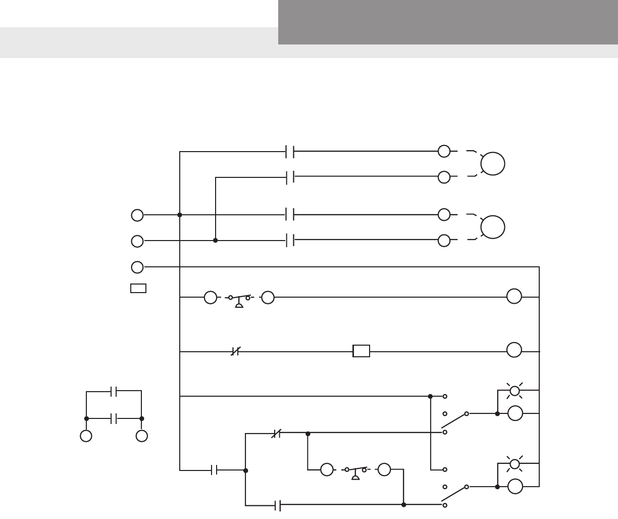
PAGE 32
Residential Water Systems
Goulds Water Technology,
Bell & Gossett, Red Jacket Series, CentriPro
1
2
1T
2T
PUMP NO. 1
1
2
PUMP NO. 2
3 HP MAX
S1
S2
S2
RUN
HAND
OFF
AUTO
S2
RUN
HAND
OFF
AUTO
3 4
A
A
LAG PUMP ON/OFF
R1
1 2
LEAD PUMP
R1
TD A
R1
L1
L2
N
GND
230 VAC
SINGLE PHASE
60 HZ
5 6
S1–AUX
S2–AUX
TO
CHEMICAL
FEED PUMP
FACTORY WIRED FOR 230 VAC.
FOR 115 VAC POWER SUPPLY,
WIRE HOT LEG TO (L1) AND
NEUTRAL TO (L2), JUMP
(L2) TO (N).
WIRING DIAGRAMS AWA501/AWA502
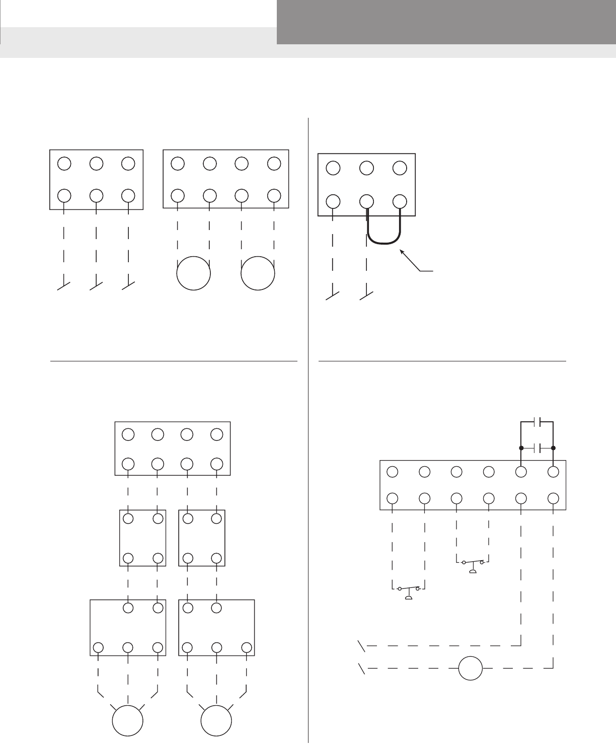
PAGE 33
Residential Water Systems
Goulds Water Technology,
Bell & Gossett, Red Jacket Series, CentriPro
PUMP
NO. 1PUMP
NO. 2
L1 L2 N121 2
1T 2T
INCOMING
SINGLE PHASE
POWER
230 VAC ONLY
POWER CONNECTION 230 VOLT
AWA501, AWA502
L1 L2 N
INCOMING
SINGLE PHASE
POWER
115 VAC ONLY
POWER CONNECTION
AWA501 115 VOLT
FACTORY WIRED FOR 230 VAC.
FOR 115 VAC POWER SUPPLY,
WIRE HOT LEG TO (L1) AND
NEUTRAL TO (L2), JUMP
(L2) TO (N).
FIELD-INSTALLED
JUMPER
1212
1T 2T
OPTIONAL CENTRIPRO CONTROL BOX
AND PUMPSAVER WITH
AWA501 AND AWA502 ONLY
PUMP
SAVER PUMP
SAVER
CONTROL BOXCONTROL BOX
PUMP
NO. 1PUMP
NO. 2
1234
FIELD CONNECTIONS:
AWA501, AWA502
56
S1-AUX
S2-AUX
LEAD PUMP
START/STOP
PRESSURE SWITCH
LAG PUMP
START/STOP
PRESSURE SWITCH
(OPTIONAL)
SEPARATE
115 VAC
SUPPLY
CHEMICAL FEED PUMP (OPTIONAL)
WIRING DIAGRAMS POWER/PUMP CONNECTIONS: AWA501/AWA502
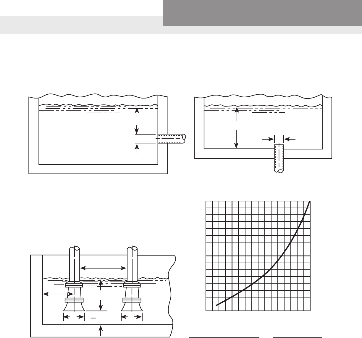
PAGE 34
Residential Water Systems
Goulds Water Technology,
Bell & Gossett, Red Jacket Series, CentriPro
• Insure that the size and minimum liquid submergence, over the suction inlet, is sufcient to prevent air from
entering suction through a suction vortex. See typical intake piping arrangement in following diagrams.
TO PREVENT A SUCTION VORTEX
H min.
DD
H min.
DD
1.5D
min.
3.0D
min.
H min.
D min.
2
16
15
14
13
12
11
10
9
8
7
6
5
4
3
2
1
H = Min. Submergence in feet
H
12345678910111213141516 V
V = Velocity in feet per second =
Quan. (GPM) x 0.321
Area (inches)2
GPM x 0.4085
D2
or
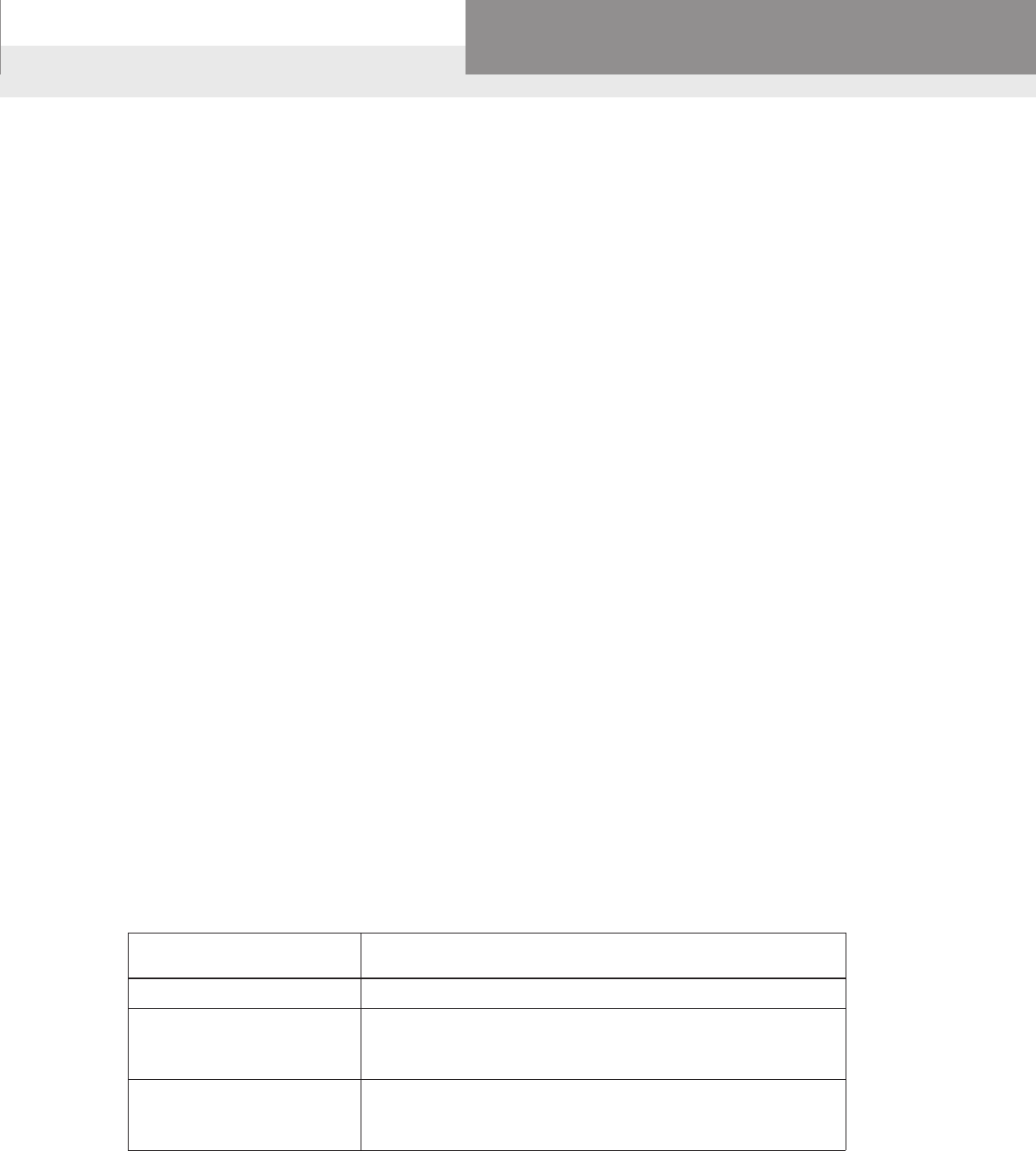
PAGE 35
Residential Water Systems
Goulds Water Technology,
Bell & Gossett, Red Jacket Series, CentriPro
OPERATION AND MAINTENANCE SUBMERSIBLE PUMP CHECK VALVES
OPERATION
Check valves are designed to give years of trouble free operation without maintenance when properly installed
and in a properly selected pumping application with regards to ow and maximum system pressures.
CONSTRUCTION
Check valve bodies have been constructed to handle the rated system ow and pressures as stated and in
addition support the weight of the submersible pump, pipe and the water in the riser pipe. In addition the valves
have been uniquely designed to absorb some of the hydraulic water shocks associated with well water pumping
when the check valve installation instruction are followed below.
IMPORTANT INSTALLATION INSTRUCTIONS
If the installation instructions are not followed warranty or any warranty claims may be void.
NOTE: On initial system start-up gradual priming of vertical water column is recommended to avoid valve
damage due to water shock.
It is very important to install a check valve properly to help insure a trouble free water system. If the installation
instructions are not followed warranty or any warranty claims may be void. On the back of this page is a diagram
of a typical submersible valve installation (Fig. 1).
A. Pipe ow: When selecting a submersible check valve insure that the valve is sized properly to ows
normally not to exceed 10 feet per second. Higher ow velocities will increase friction losses, hydraulic
shocks and the possibility of destructive water hammer (explained below in more detail) leading to severe
system failure.
B. System pressure: It is important to take the total system hydraulics into the calculation and not only the
pump’s well setting when selecting valve type and model. In general, valves are pressure rated 400 psi or
920 feet of water pressure. This does not mean that a valve can be set at a well depth of 920 feet. To elevate
and reduce the hydraulic shocks in the riser pipe it is recommended that a check valve be installed every
200 feet in the riser pipe. See Recommend Check Valve Installation chart below.
C. Prior to installing check valve: Make sure that the check valve is free from defects and that the valve’s
spring-loaded poppet mechanism is operating freely. Remove any foreign material (IE. PIPE DOPE) from
valve seat.
D. Install check valve vertically with arrow pointed up in direction of liquid ow.
E. In submersible pump applications, the rst check valve should be installed directly on the discharge head
of the pump or maximum one pipe length (20 feet) above pump.
F. If the pump has a built-in check valve, the second check valve should be installed no more than 25 feet
above the lowest pumping level in the well.
Submersible pump Recommended Check Valve Installation
setting in well
200 feet or less One check valve on pump discharge and one on
200 feet to One check valve on pump discharge and additional check
600 feet valves installed at maximum 200 ft intervals and one at the
surface of well.
600 feet to 800 feet One check valve on pump discharge and additional check
(for deeper settings valves installed at maximum 200 ft intervals and one at the
contact factory) surface of well.
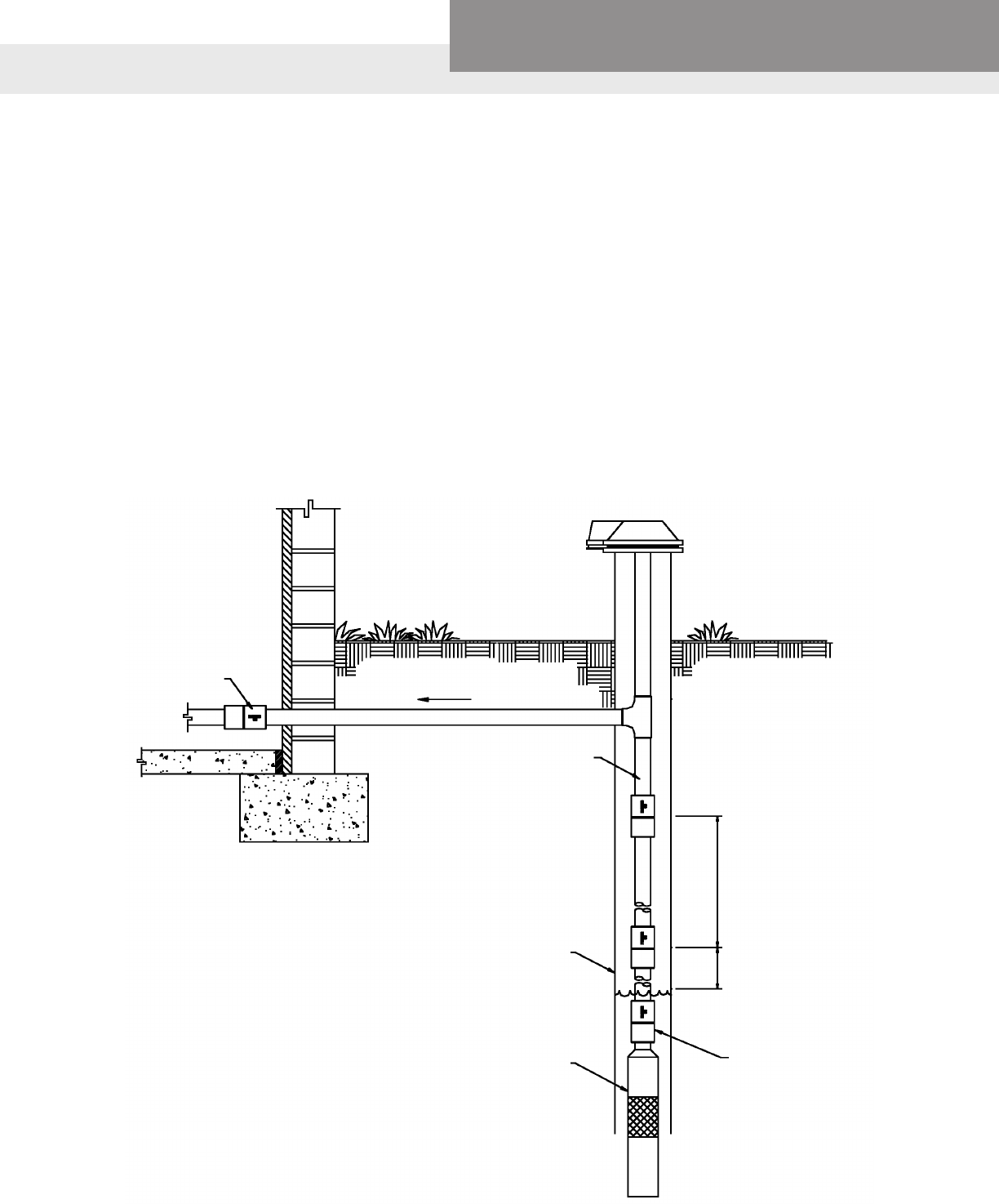
PAGE 36
Residential Water Systems
Goulds Water Technology,
Bell & Gossett, Red Jacket Series, CentriPro
WATER HAMMER
Water pumped and owing through a piping system has a certain amount of energy (weight x velocity). If the
pumping is stopped, the water continues to move and its remaining energy must be absorbed in some way. This
absorption of energy can sometimes create undesirable noise and/or damage. This is called water hammer.
Water hammer can destroy piping systems, valves and related equipment. Water hammer varies in intensity de-
pending on the velocity with which the water is traveling when the pump shuts down. It is very important for the
installer to realize water hammer potential, and he must take this into consideration when sizing the system and
deciding what material the valves should be made from.
It has been proven that for every foot per second of velocity 54 psi of backpressure is created. This means, in a
1" pipe, a ow of only 10 gpm could create a back pressure of 370 psi or more when the pump shuts down and
the water column reverses. In a 4" pipe, a ow of 350 gpm could create a backpressure of 860 psi. This does not
take in consideration the weight of the water column in the well. Check valves are designed to help lessen the
sometimes-damaging effects of water hammer on piping and related equipment.
Check valve installation instructions provided courtesy of Danfoss Flomatic Corp.
Figure 1
OPERATION AND MAINTENANCE SUBMERSIBLE PUMP CHECK VALVES
CHECK VALVE
AT SURFACE TO PLUMBING SYSTEM
RISER PIPE
WELL CASING
SUBMERSIBLE
PUMP
200 FT MAX
BETWEEN
VALVES
LOWEST CHECK VALVE
25 FT MAX ABOVE
PUMPING LEVEL
CHECK VALVE MOUNTED
DIRECTLY ON PUMP
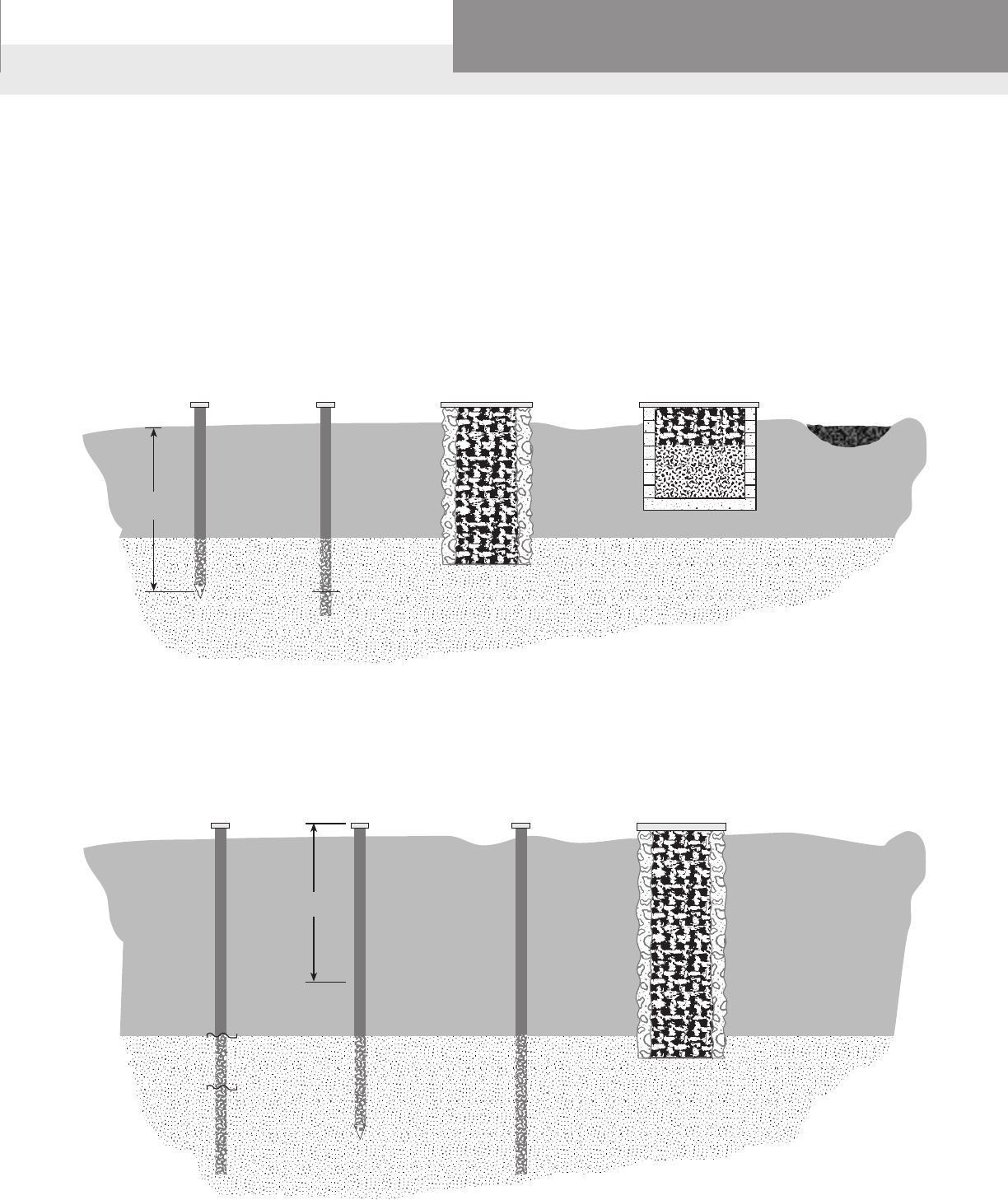
PAGE 37
Residential Water Systems
Goulds Water Technology,
Bell & Gossett, Red Jacket Series, CentriPro
25 ft.
SOURCES OF WATER
A source of water or a well is often referred to as shallow or deep. These terms are referring to the depth of the
water source or well.
A shallow well is one where the water is within 25 feet of the ground surface.
A deep well is where the static water level is more than 25 feet down.
The standing water level in a well is called the static level. This is the water level when the pump is not operat-
ing. When the pump comes on and is running there often is a change in the water level. This is referred to as
drawdown. The drawdown occurs and the water level reaches what is referred to as the pumping level. This is
the operating level of the pump. The lowest level to which the water will drop is the level from which it must be
pumped.
25 ft.
Driven Well Drilled Well Dug Well Cistern Spring, Lake, or
Surface Water
A SHALLOW WELL
Is any source of water where the water is within 25 feet of ground level. When water is pumped from a well the
water level will draw down. The lowest level to which it will drop is the level from which it must be pumped.
A DEEP WELL
Is any source of water where the low water level is more than 25 feet below the ground level.
Driven Well Drilled Well Dug Well
Static Level
Pumping
Level
Draw
Down
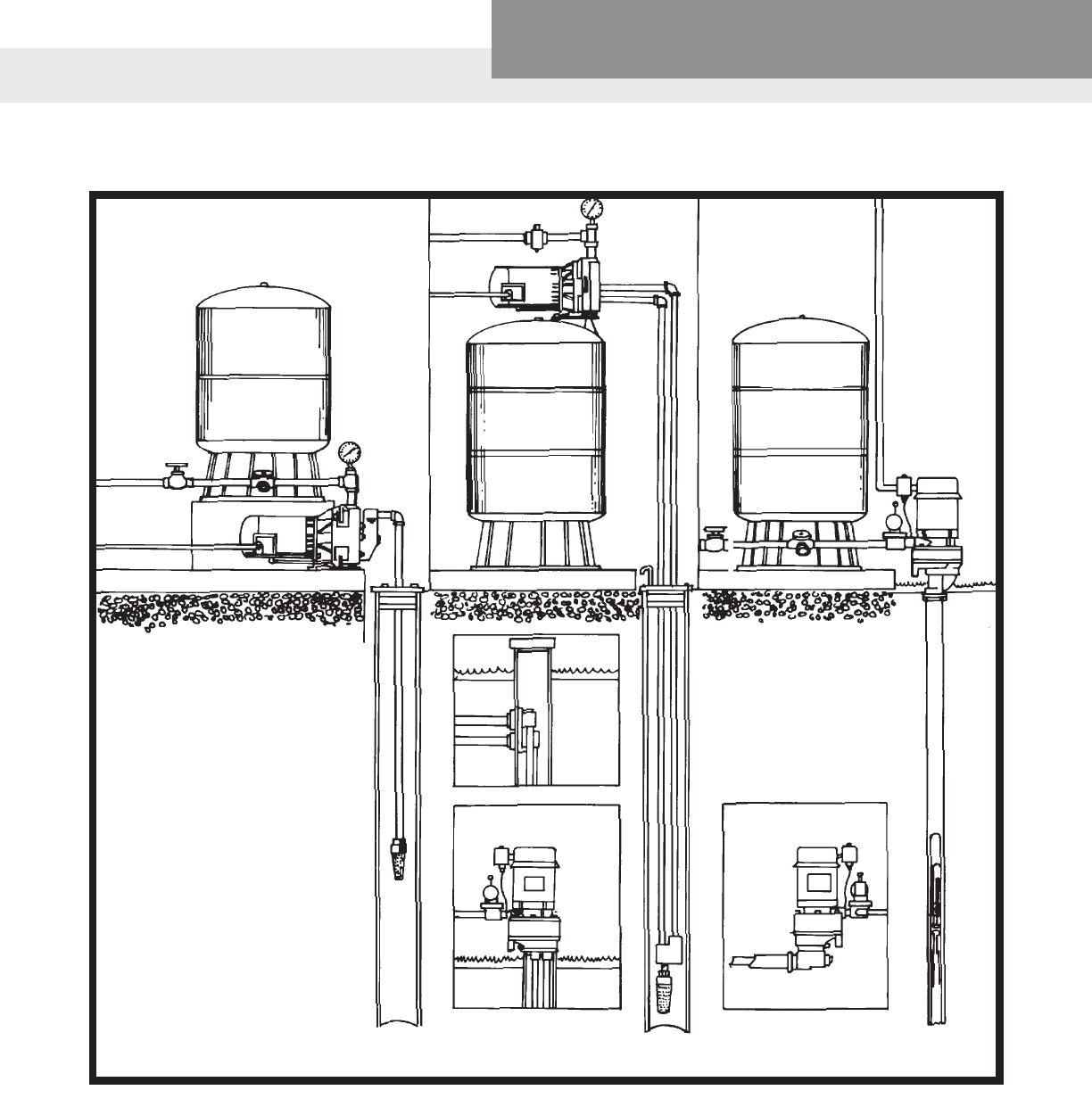
PAGE 38
Residential Water Systems
Goulds Water Technology,
Bell & Gossett, Red Jacket Series, CentriPro
Typical Jet Pump Installations
SHALLOW
WELL SYSTEM
TWIN PIPE
DEEP WELL
SYSTEM
PACKER
DEEP WELL
SYSTEM
2-PIPE
PITLESS
ADAPTER
OFFSET ADAPTER
OVER THE WELL
JET PUMPS TYPICAL INSTALLATIONS
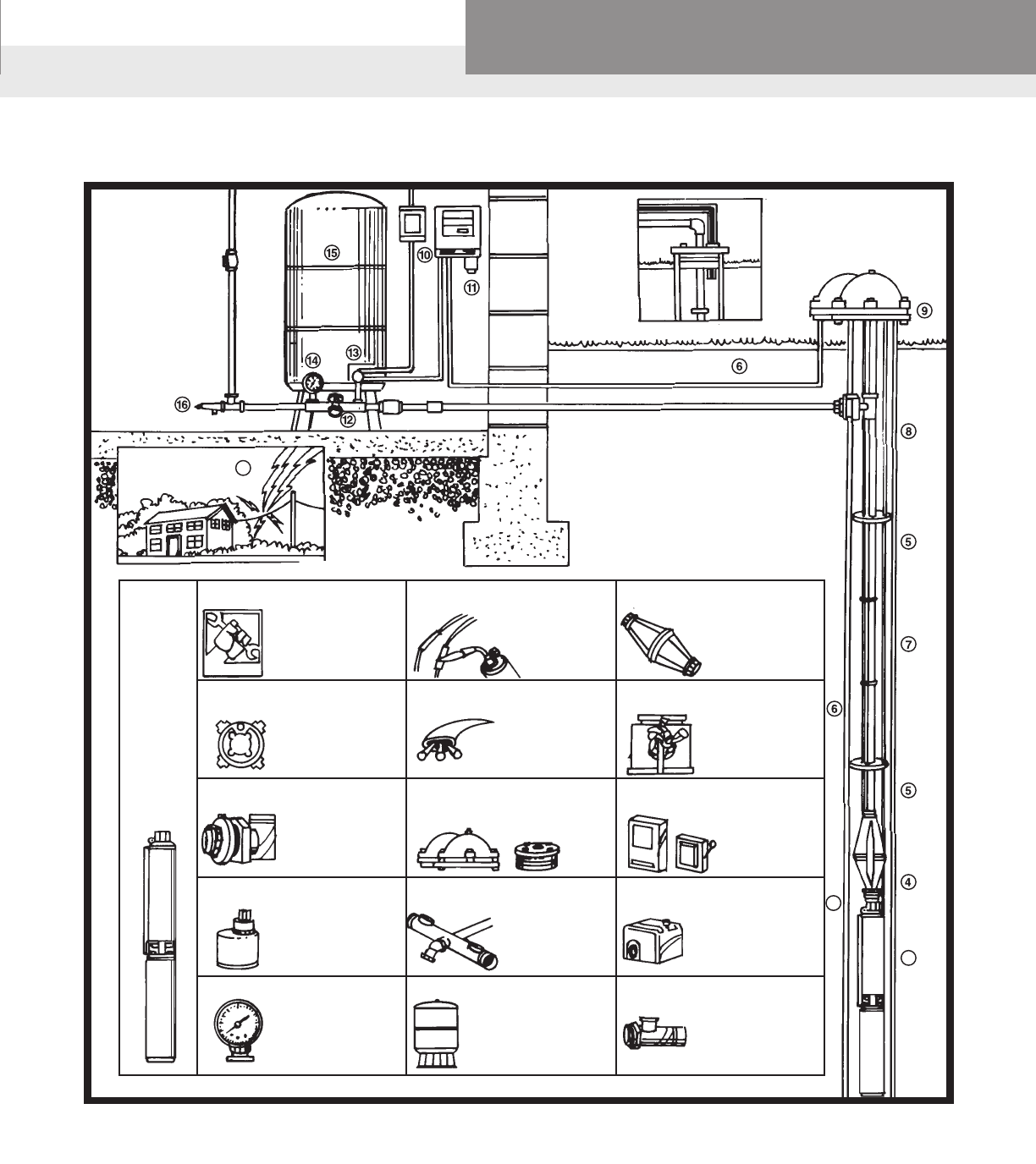
PAGE 39
Residential Water Systems
Goulds Water Technology,
Bell & Gossett, Red Jacket Series, CentriPro
2. WARRANTY CERTIFICATE
1. PUMP
Two or three
wire models
available.
5. TORQUE STOPS
11. LIGHTNING ARRESTOR
8. PITLESS ADAPTER
14. PRESSURE GAUGE
3. SPLICE KIT 4. TORQUE ARRESTOR
6. ELECTRIC CABLE
9. WELL CAP OR
WELL SEAL
12. FITTINGS
15. STORAGE TANK
7. SAFETY ROPE
10. CONTROL BOX
13. PRESSURE SWITCH
16. PRESSURE RELIEF
VALVE
(include stop and waste valve in illustration)
Connecter crimps
and heat-shrink tubing
seals wire lead
connections to
electric.
Either three-wire or
two-wire. Selection of
proper size wire assures
required voltage to
motor.
Keeps debris out of well.
Allows entry into the well.
Offers water storage for
fewer lump cycles.
Provides air cushion to
operate against. Tank
should be sized so that
draw down is equal to
capacity of pump.
Plumbing fittings usually included
in typical water system
hook-ups include tank
cross tee, boiler drain
fittings, unions and
other necessary items.
Absorbs thrust of motor
start-ups; keeps pump
centered in well.
Various types are
available.
Sometimes used to
support the weight of the
pump and prevents pump
from falling to the bottom
of the well.
Contains components of
the motor required with
all three-wire models.
ABOVE GROUND
INSTALLATION
1
2
3
5-year Warranty
covers pump with
CentriPro motor against
failure due to wear,
abrasion, corrosion
or even lightning.
Spaced at regular
distances apart in the
well, to keep wire from
rubbing against the
side of the wall.
For underground
connection of well
pipe to horizontal pipe
providing a sanitary
seal.
Recommended for units
over 1 1/2 h.p. Models
up to 1 1/2 h.p. have
lightning protection
built right into the motor.
Indicates system
pressure at all times.
Senses system pressure
and automatically turns
pump on and off.
Protection against pres-
sure build-up. Particularly
vital where the pump is
capable of producing
more pressure than the
working limits of the tank.
4" SUBMERSIBLES TYPICAL INSTALLATIONS
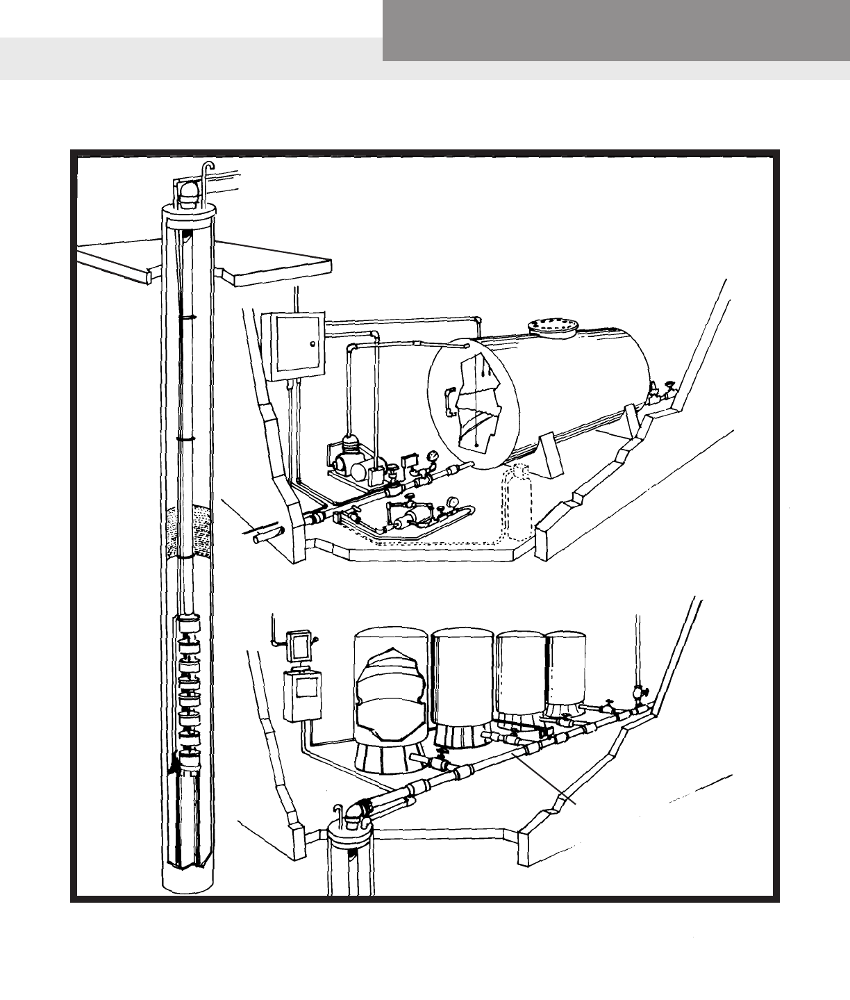
PAGE 40
Residential Water Systems
Goulds Water Technology,
Bell & Gossett, Red Jacket Series, CentriPro
Typical High Capacity Submersible Pump Installations
NOTE: Header pipe must be large
enough to get enough water to all
tanks equally.
HIGH CAPACITY SUBMERSIBLE PUMPS TYPICAL INSTALLATIONS
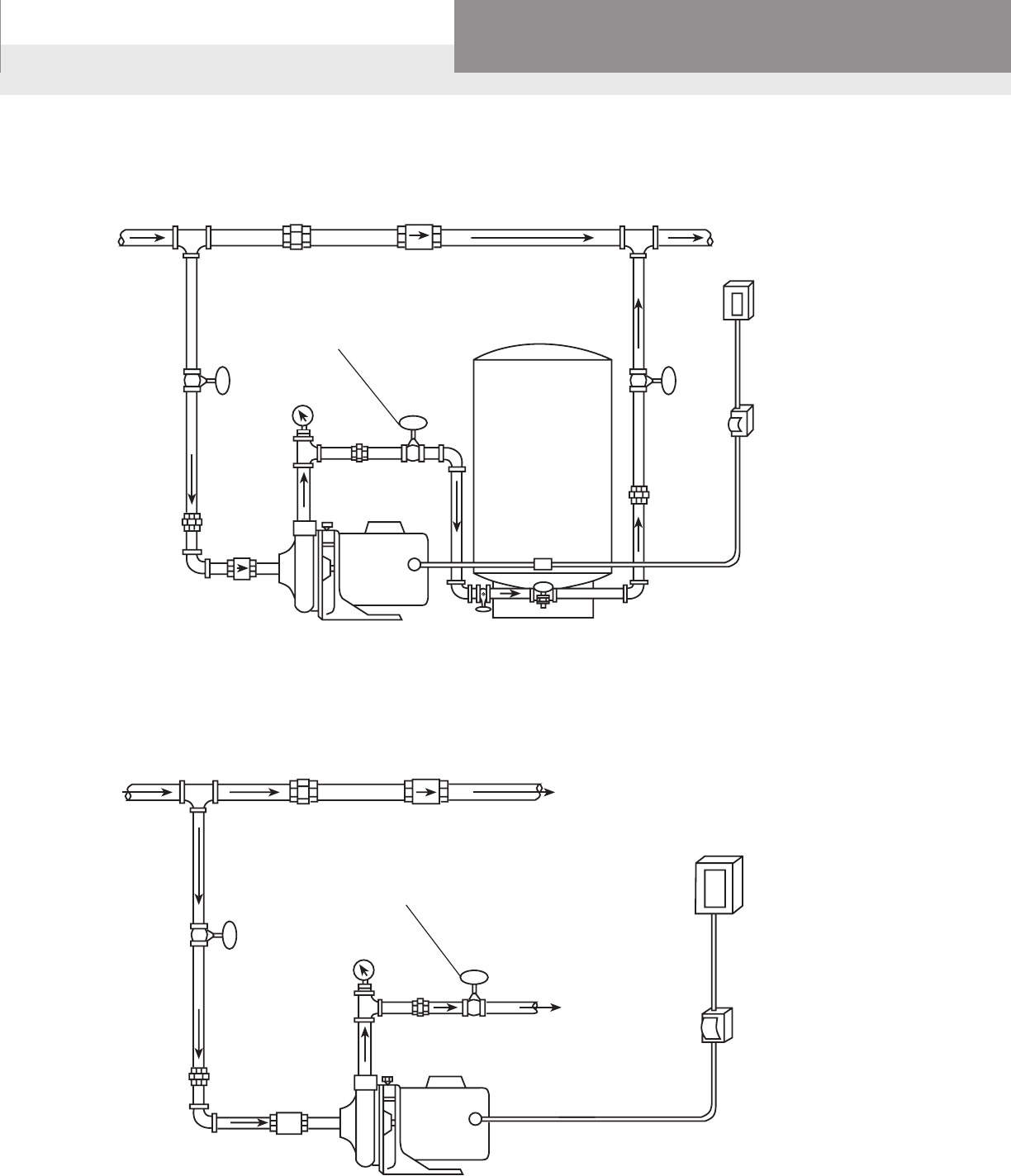
PAGE 41
Residential Water Systems
Goulds Water Technology,
Bell & Gossett, Red Jacket Series, CentriPro
AUTOMATIC OPERATION
HOUSEWATERMAIN
MANUAL OPERATION
HOUSEWATERMAIN
UNION CHECK
VALVE
GATE
VALVE BALL
VALVE
UNION
PRESSURE
GAUGE
UNION
CHECK
VALVE
PUMPDISCHARGE
TOSPRINKLERS FUSEBOX
OR
SWITCH
MAINPOWERBOX
UNION CHECK
VALVE
GATE
VALVE BALL
VALVE
UNION
GAUGE
UNION
CHECK
VALVE
TO SIZE TANK
PROPERLY –
MATCHDRAWDOWN
OFTANKTOCAPACITY
OFPUMP.
FUSEBOX
OR
SWITCH
MAINPOWERBOX
PRESSURE
SWITCH
*RELIEF
VALVE
Useowcontrolormanualvalveondischarge
tothrottlepump.Mustbesized,orset,toload
motor below max. nameplate amps.
Useowcontrolormanualvalveondischarge
tothrottlepump.Mustbesized,orset,toload
motor below max. nameplate amps.
*NOTE:Requiredifsystempressurecanexceed100PSI.
CENTRIFUGAL BOOSTER PUMP INSTALLATIONS
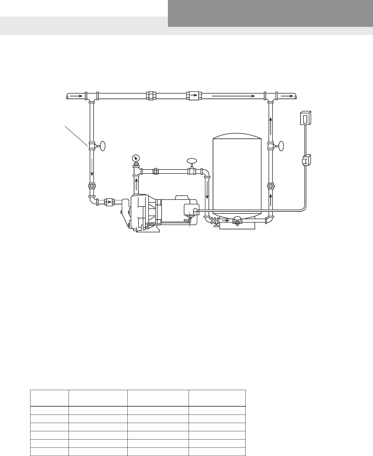
PAGE 42
Residential Water Systems
Goulds Water Technology,
Bell & Gossett, Red Jacket Series, CentriPro
AUTOMATIC OPERATION
JET PUMP - SHALLOW WELL OR CONVERTIBLE WITH INJECTOR
HOUSEWATERMAIN
UNION CHECK
VALVE
BALL
VALVE GATE
VALVE
UNION
GAUGE
UNION
CHECK
VALVE
TO SIZE TANK
PROPERLY –
MATCH
DRAWDOWN OF
TANKTOCAPACITY
OFPUMP.
FUSEBOX
OR
SWITCH
MAINPOWERBOX
PRESSURE
SWITCH
*RELIEF
VALVE
Useowcontrol
or manual valve on
suction to throttle
pump.Mustbesized,
orset,toloadmotor
below max. nameplate
amps.
*NOTE:Requiredifsystempressurecanexceed100PSI.
SIZING THE BOOSTER PUMP
Booster system pumps are sized the same as shallow well jet pumps with the exception being, we add the
incoming city pressure to what the pump provides. The required ow is determined by the number of bathrooms
or number of xtures being used at any given time. City water is supplied under pressure, low incoming pressure
is caused by undersized, crushed or severely corroded pipes or large elevation differences, such as a hill,
between the city water line and the house.
Verify the incoming pressure with the water owing to nd the “dynamic suction pressure”, static pressure is what
you see with no water owing. Use the dynamic suction pressure to calculate pump performance and selection.
The J5S and the high pressure version, J5SH are very popular as booster pumps. The J5SH is a good choice
for booster applications because of its narrow ow range and higher pressure capability. In the absence of
performance data for 0’ we use the 5’ Total Suction Lift performance data. Add the incoming dynamic pressure
to the pump’s discharge pressure to nd the total discharge pressure. Make a chart showing the ow, incoming
dynamic pressure, pump discharge pressure and total discharge pressure for each job. It would look like this if
using a J5SH pump with 15 PSI of incoming dynamic pressure:
Flow Rate Pump Discharge Incoming Dynamic Total Discharge
GPM Pressure (PSI) Pressure (PSI) Pressure (PSI)
11.5 20 15 35
11.3 30 15 45
11 40 15 55
7.7 50 15 65
4.8 60 15 75
0 83 15 98
JET BOOSTER PUMP INSTALLATIONS
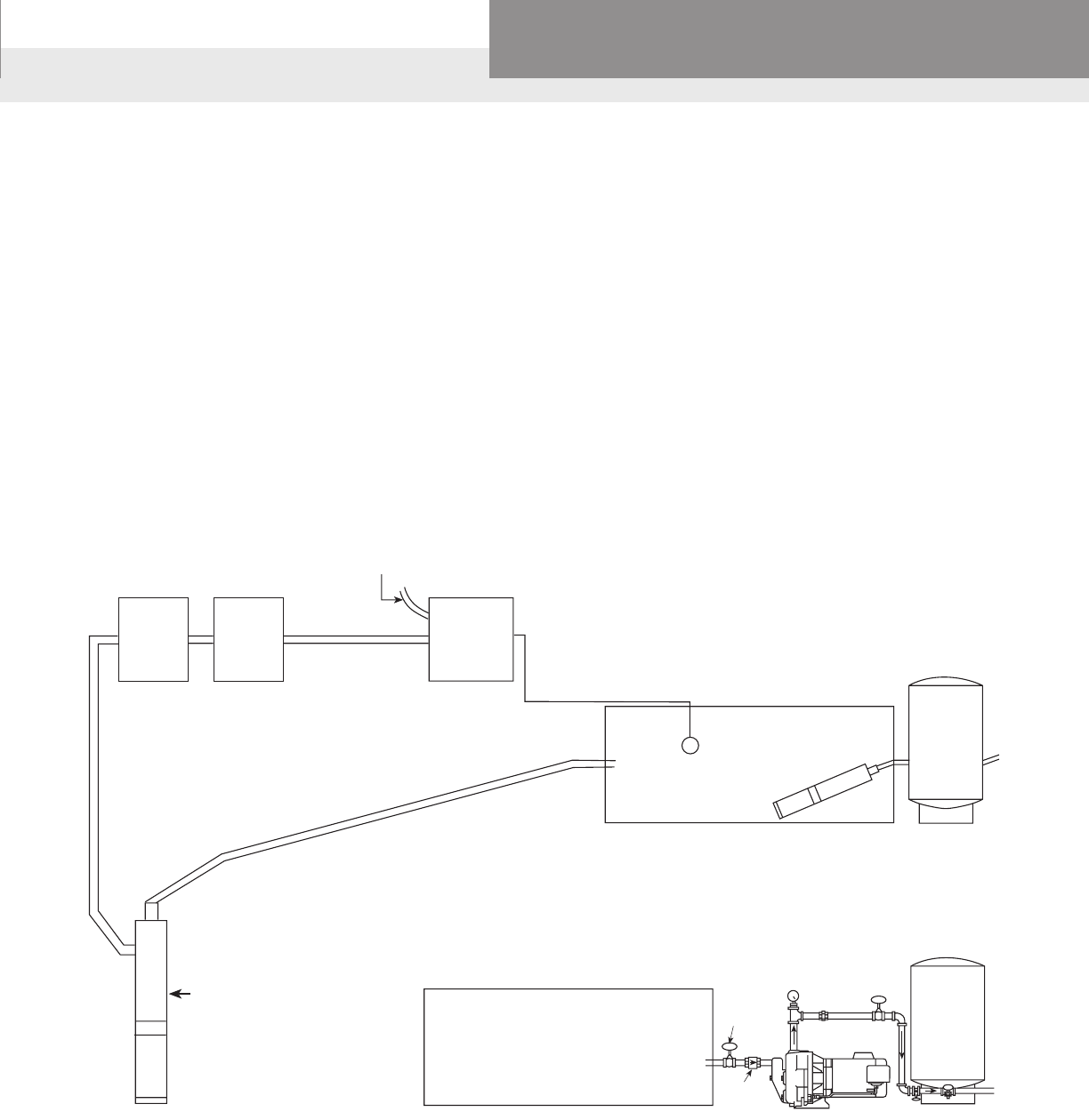
PAGE 43
Residential Water Systems
Goulds Water Technology,
Bell & Gossett, Red Jacket Series, CentriPro
PUMP
CONTROL
BOX
PUMP
SAVER MAGNETIC
CONTACTOR
INCOMING POWER
SUPPLY
NORMALLY
CLOSED
SWITCH
STORAGE TANK
WELL
PUMP
PUMP
PRESSURE
TANK
IF A 2 WIRE PUMP IS USED
DELETE THE CONTROL BOX
STORAGE TANK GATE
VALVE
CHECK
VALVE
JET PUMP
PRESSURE
TANK
COMPONENTS FOR A LOW YIELD WELL WITH A BOOSTER SYSTEM
• Submersible or jet pump to ll atmospheric tank
• Storage tank - usually at least a 500 gallon size
• Magnetic contactor - makes wiring simple and fast
• Normally closed oat switch for automatic operation
• Booster pump - sub or jet to pressurize water from storage tank
• Pressure tank sized for 1 minute minimum pump cycle
• Pressure switch
• Check valve and gate valve between the open storage tank and jet pump,
or a gate valve between the submersible and pressure tank
LOW YIELD WELL COMPONENTS
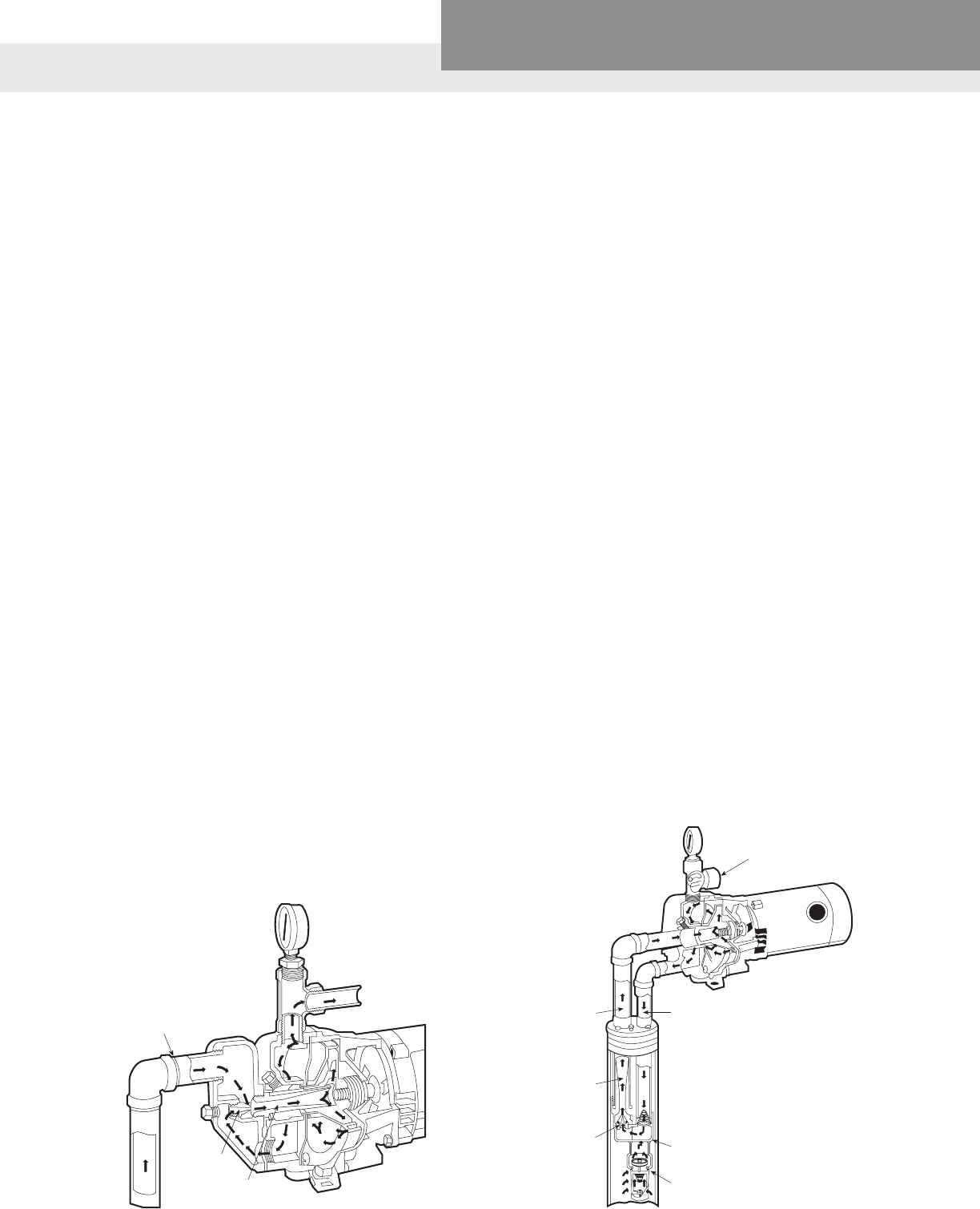
PAGE 44
Residential Water Systems
Goulds Water Technology,
Bell & Gossett, Red Jacket Series, CentriPro
TYPES OF PUMPS – JET SYSTEMS
TherstquestionwithJetPumpsiswhatisthesuctionchamberand
how is the vacuum created.
TheJetAssemblyitselfformsthesuctionchamberandthevacuumis
createdbytheveryhighvelocityofastreamofwaterpassingthrough
thejet.Basically,thejetassemblyiscomposedoftwoparts.First,a
nozzlewhichproducesthehighvelocitystreamofwater.Thishigh
velocitystreamofwaterisinjectedthroughasmallcompartment
whichisthesuctionchamber,therebycausingthevacuum.Obviously,
the suction pipe is connected to this compartment or suction chamber.
Thevacuumcausedbythejetpermitsthegreaterpressureof
atmosphereonthesurfaceofabodyofwatertoforcewaterintothe
suction chamber.
ThesecondbasicpartoftheJetAssemblyistheventuritube.Itis
installed in the discharge of the suction chamber. Its function is to
convertthevelocityofthewaterintopressure.Thisisaccomplished
bytheshapeofitswaterpassage.Perhapsyoucanbestvisualize
thisbythinkingofanozzleinreverse.Thenozzlespeedsuptheow
ofthedrivewaterconvertingpressureintovelocityandwhenithas
passedthroughthesuctionchamber,theventurislowsitdownagain
convertingthevelocitybackintopressure.
“Drive water” is that water which is piped under pressure to the jet
assemblyorsuctionchamber.Thedischargefromthesuctionchamber
orjetassemblyiscomposedofboththedrivewaterandthatwater
pumped from the well. The total amount pumped from the well can be
usedasdischargefromthesystemandistheoutputorcapacity.
SHALLOW WELL JET PUMP
From the foregoing discussion it is obvious that the operation of the
JetsystemisdependentonthecombinedfunctionsofboththeJet
Assemblyorsuctionchamberandthecentrifugalpump.Also,that
thesetwomaincomponentsofthesystemareentirelyseparateand
their locations with respect to each other is a matter of design.
Inshallowwelljetpumpsthejetassemblyisbuiltintothepump
casingasintheGouldsWaterTechnologyJ5S.Or,thejetassembly,
shallowwelladapters,canbeboltedtothecentrifugalpump.Ineither
casethereisonlyonepipeextendingintothewell...thesuctionpipe.
DEEP WELL JET PUMP
TheonlybasicorfundamentaldifferencebetweenShallowWelland
DeepWellJetPumpsisthelocationoftheJetAssembly.Itmustalways
be located in such a position that the total suction lift between it and
the pumping level of the water to be pumped does not exceed that
whichcanbeovercomebythepressureofatmosphere.This,ofcourse,
means that when this pumping level is at a distance lower than the
groundlevelwhichcannotbeovercomebyatmosphericpressure,the
JetAssemblymustbelocatedatleastvefeetbelowthelowwaterin
the well.
Wemusthaveaclosedcompartmentinwhichtoinstallthenozzleand
the venturi and to form the suction chamber. This part is called the jet
body.Itsshapeissuchthatitwilltintothecasingofadrilledwelland
thepipeconnectionsarelocatedforaccessibility.Therearetwoonthe
topside,oneforconnectiontothepressurepipewhichsuppliesthe
drivewater,theotherforconnectiontothesuctionpipewhichreturns
both the drive water and the water pumped from the well. For this
reason,thisconnectionisonepipesizelargerthanthatforthepressure
pipe. Water from the well enters through a third opening which is on
thebottomsideofthejetbody.
ThelastaccessoryfortheJetSystemisthepressurecontrolvalve.Itis
a valve installed in the discharge piping from the centrifugal pump
between the pump and the tank; in the pump when the pump is
mountedonatank.Usedonlyindeepwellsystems,itspurposeitto
assure a minimum operating pressure for the jet.
Install Check
Valve Here
Or
Foot Valve
at End of
Suction Pipe
Nozzle
Venturi Foot Valve
Twin Pipe
Deep Well
Jet Assembly
Nozzle
Venturi
Suction
Pipe Pressure Pipe
Pressure
Control
Valve (AV22)
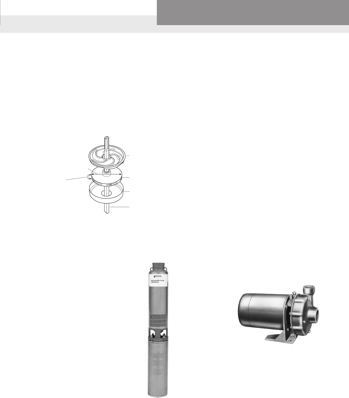
PAGE 45
Residential Water Systems
Goulds Water Technology,
Bell & Gossett, Red Jacket Series, CentriPro
SUBMERSIBLE PUMP
Submersiblepumpsaresonamedbecausethewholeunit,pumpand
motor is designed to be operated under water. This means the pump
doesnothavetobeprimed.Onceinstalledandturnedon,waterows
up the pipe.
Thepumpendisamultistage(manyimpellers)centrifugalpump,
close coupled to a submersible electric motor. All of the impellers of
themultistagesubmersiblerotateinthesamedirectionbyasingle
shaft.Eachimpellersitsinabowlandtheowfromtheimpellerisdi-
rectedtothenextimpellerthroughadiffuser.Thesethreeparts(bowl,
impeller and diffuser) are known as a stage.
Thecapacityofamultistagecentrifugalpump(submersible)islargely
determinedbythewidthoftheimpelleranddiffuser,regardlessofthe
numberofstages.Thepressureisdeterminedbythediameterofthe
impeller,thespeedatwhichitrotatesandthenumberofimpellers.
Thediameterislimitedtothesizeofwellsdrilled.Mostsubmersibles
aredesignedtotinfourorsixinchwells(orlarger).
A½HPpumpwithsevenimpellers(designedforcapacity)
woulddelivermorewaterat80'thana½HPpumpwith
15 impellers (designed for pressure) but the latter pump
would be able to raise water from a greater depth.
Well water enters the unit through screened openings
at the middle of the unit between the pump and motor.
Thereisonlyonepipeconnectionwhichisatthetopof
the pump. This is the discharge pipe. A check valve is
located at the top of the unit to prevent water from the
systemdrainingbackwhenthepumpisn’trunning.
Submersiblepumpsaresomuchmoreefcientthan
jet pumps and the installation so much simpler that a
submersiblepumpshouldbeconsideredrstforallpump
applicationswherethephysicaldimensionsofthesource
of the water will accommodate the unit in a submerged
position.
Example: 60 ft. pumping level;
30-50lbs.Pressure.
½HPsubmersible .......................................................... 11 gpm
½HPjetsystem................................................................6 gpm
CENTRIFUGAL PUMP
The centrifugal pump does two things. It circulates the drive water at
thepressurerequiredtoproducethenecessaryvelocityintheJet.It
also boosts the pressure of that water being pumped from the well
deliveringitthroughthedischargeofthesystematasatisfactory
servicepressure.Sincetheonereturnpipefromthejetassembly
containsboththesequantitiesofwater,thisreturnpipeisconnected
direct to the suction opening of the centrifugal pump. The action of
the centrifugal pump can be thought of as that of a paddlewheel. The
impeller is a multi-vane (or blade) wheel and its design is such that
itssize,shapeandspeedimpartsufcientenergytothewaterinthe
systemtocirculateitatthedesiredrate.
Asthewaterisdischargedfromthecentrifugalpump,itisdivided.The
drivewater,orthatamountrequiredtooperatetheJetispipeddirectly
totheJetthroughthepressurepipe.Itiscontinuouslyrecirculatedso
long as the centrifugal pump is running. That amount pumped from
thewellisdischargedfromthecentrifugalpumpdirectlyintothetank
andisthecapacityofthesystem.
Centrifugal Pump Characteristics
•ImpellerattachedtoaMotor/Driver
•ImpellerdrawstheHPofftheMotor/Driver
• Flexible machine; capable of a range of performances at good ef-
ciencies
•Willoverloadmotor(pumpsmaximumcapacity)
•LimitedSuctionLiftcapability(15-25')
•Impellermakesownpressure(PSI)
•Addsitspressuretoanyincomingpressure
•Poorair-handlingcapability(Cavitation,lossofsuction/prime,and
air-binding)
Diffuser
Impeller
Bowl
Shaft
Diameter of Impeller
Affects Pressure
Width of Impeller Vanes
Affects Capacity
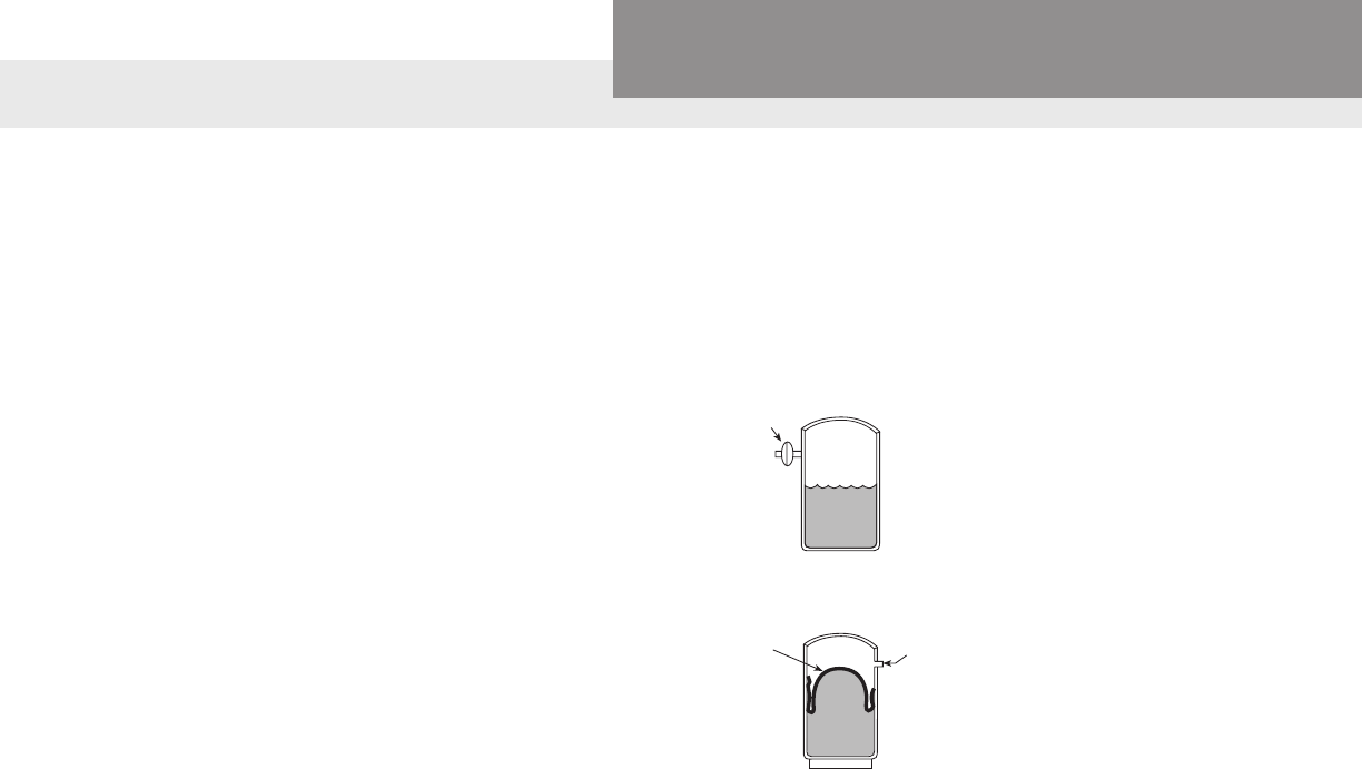
PAGE 46
Residential Water Systems
Goulds Water Technology,
Bell & Gossett, Red Jacket Series, CentriPro
ACCESSORIES
Whenapplyingapumptoanyspecicproblempertainingtodomestic
watersupply,ourobjectiveinpracticallyeverycaseshouldbetopro-
vide automatic running water under pressure – a water service compa-
rabletothatwhichmightbeexpectedfromconnectiontoacitywater
main.But,apumpalonecanhardlyperformtheseveralnecessary
functions.Certainotheraccessoriesarenecessary,andthecombination
ofthemallformswhatwecallawatersystem.
MOTORS
Therstaccessoryisthedrivemediumwhichonpracticallyallwater
systemsoftodayisanelectricmotor.Youshouldrememberthatsome
ofourpumps,inparticularthejetpumpsinlargemotorsizesand
submersiblepumps,arefurnishedwithmotorsofcurrentcharacteris-
ticsasspecied.Therefore,whenorderingthese,wemustbeadvised
the electrical characteristics.
PRESSURE SWITCH
Thenextaccessoryrequiredisapressureswitchtostartandstopthe
motorautomaticallyatapredeterminedpressure.Atubeconnectsthe
switchtosomepointinthesystemonthedischargesideofthepump.
Thepressureinthesystemthenactsdirectlyonadiaphragminthe
switch which in turn actuates the contacts in the switch.
PRESSURE TANKS
Therateatwhichwatercanbeusedinahome,school,motel,orany
other place can be as little as one gallon a minute (60 gallons per
hour) (brushing teeth or rinsing hands). Or the maximum can be
hundreds or thousands of gallons per hour depending on the number
ofwaterusingxturesand,orappliancesinuseatthesametime.
Apumpcapableofdeliveringacapacityequaltothemaximumde-
mandcannotnecessarilybethrottledtotheminimumdemand.
Themainpurposesofapressuretankaretopressurizethesystem
tomakeitoperateautomaticallyandtoproperlycyclethepumpto
properlycoolthemotor.Thispreventsexcessiveshortcycling(too
rapidstartingandstopping).Thepumpcapacityandsizemotorshould
alwaysbeconsidered.Thelargeramotorisinhorsepowerthemore
startingpowerrequired;therefore,thelessfrequentlyitshouldbe
started.
Itisgoodpracticetosizethetanktorequirethepumptorunatleast
oneminutepercyclewhenusingfractionalhorsepowermotorsand
two to three minutes for larger motors.
Therearetwobasictypesoftanksinusetoday:
Conventional or
Galvanized Type
Requires an air volume
control device to keep
proper amount of air
cushion in the tank.
Sealed Diaphragm Type
Water and air are perma-
nently separated by sealed
diaphragm; therefore, the
amount of air never changes.
The amount of draw-off also
never changes.
RELIEF VALVE
Asaprecautionorprotectionagainstthepossibilityoftheswitch
becoming stuck at some time allowing the pump to continue running
aftersufcientpressurehasbeenobtained,areliefvalveisnecessary
withallsystemscapableofdevelopingpressuresinexcessofthe
working limits of the tank. A relief valve is a spring controlled valve
locatedsomewhereclosetoorinthepumponthedischargeside,or
on the tank. The tension of the spring is so adjusted that it will permit
the valve to open and allow the water to escape if the pressure in the
systemexceedsbymorethanabout10lbs.Thatatwhichthepressure
switch is set to cut off the current to the motor.
FOOT VALVE
A foot valve is a combination check valve and strainer.
AIR
WATER
AIR VOLUME
CONTROL
AIR
WATER
AIR VALVE
DIAPHRAGM
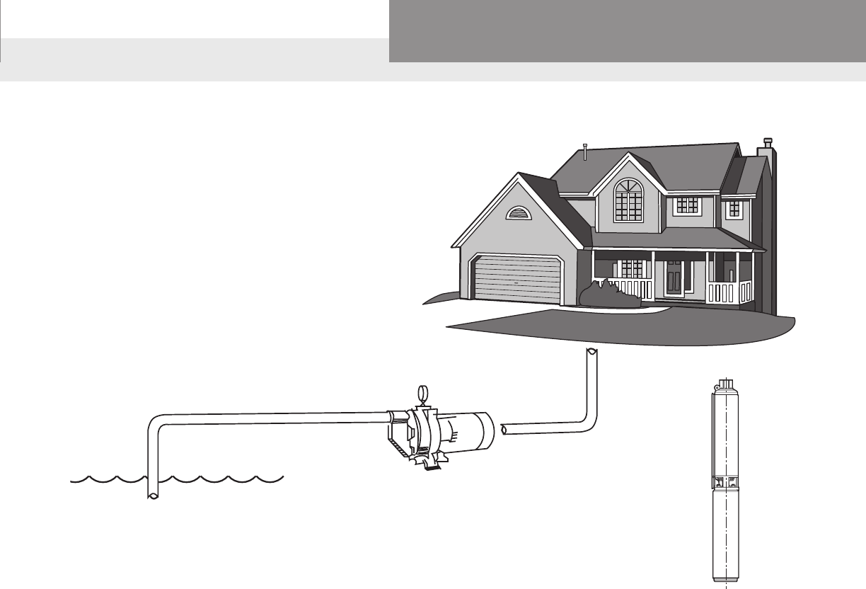
PAGE 47
Residential Water Systems
Goulds Water Technology,
Bell & Gossett, Red Jacket Series, CentriPro
THE 3 BASIC QUESTIONS
1. Capacity Needed
Howbigmustthepumpbe?
2. Well Conditions
Isashallowordeepwellpumpneeded?
3. Discharge Conditions
Howmuchpressureisneeded?
Theillustrationaboveposesatypicalwatersystemproblem.Thesourceofwaterisinnearlyallcaseslowerthanthehouseor
building.Thisiswhyapumpisneeded–toraisethewateruptothefaucetsandxtures.Thesearethethreequestionstobe
considered:
1. Capacity Needed
Howmuchwateringallonsperhourorgallonsperminuteareneeded?Thisdetermineswhatsizepumptouse.
2. Well Conditions
Whatisthetotalsuctionlift?Whatismeantby“totalsuction”?Welearnfromthiswhattoexpectfromashallowwellpumpandwhenandwhy
to use a deep well pump.
3. Discharge Conditions
Howmuchpressureisneededatthepump?Howmuchpressurewillresultatthefaucet?
Wheneverandwhereverapumpistobeused,thecorrectanswerstothesethreequestionswilltelltheactualpumpingconditionsorspecically–
whatisrequiredofthepump.Withthisinformation,youcanalwaysselecttherightpumpfromthecatalog.
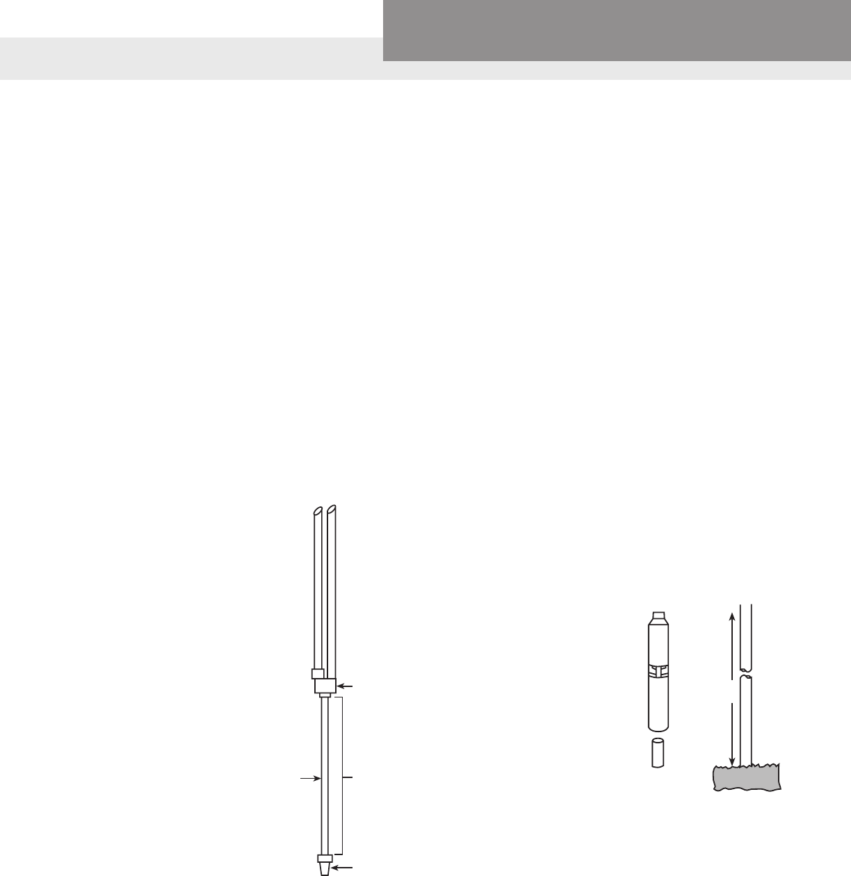
PAGE 48
Residential Water Systems
Goulds Water Technology,
Bell & Gossett, Red Jacket Series, CentriPro
1. CAPACITY NEEDED
Howmuchwaterisavailable? Howmuchwaterisneeded? Howlargemustthepumpbe?
LIMITING FACTORS
Howmuchwaterisavailable?
Before we select a pump based
on need we must determine if
thesupplyisadequate.Many
areas have what we refer to as
lowyieldwells,Wellrecovery
ratesmaybeaslowas1GPM
or less.
Atypicallowyield(1–2GPM)
well,cannotsupplythe10-12
GPMrequiredbyanaverage
home.Ifwepumpat12GPM
and the water enters the well
at2GPMwewillsoonrunthe
pumpdry.Thissystemwould
require a pump protection de-
vice to turn the pump off when it
runs out of water.
Fortunatelysomelowyield
wells have a great deal of water
stored in the well due to high
static water levels. There are
500' deep wells with static water
levels,whennotbeingpumped,
of 20'. A 4" well casing stores
approximately.652gallonsper
foot or 1.4 gallons per foot in
a6"well.Inthiscase,a4"well
stores 312 gallons and a 6"
stores 672 gallons. It is possible
tousea7or10GPMpumpand
not over pump the well due to
the large amount of water stored
in the casing. While lawn water-
inganddailymultipleloadsof
laundryareoutofthequestion,
this application could provide
acosteffective,reliablewater
supplywithouttheuseoflarge
expensive storage tanks and
booster pumps. The customer
should be made aware of the
limitations of the well and the
options available.
If using a deep well jet pump in
alowyieldwellyoushoulduse
a 34' tail pipe on the bottom of
thejetassembly.Thiswillpre-
vent over pumping a deep well.
SeethesectiononUsingTail
PipesintheTechnicalManualof
yourcatalog.
2" Casing
4"
Sub
Well
Too Small
2"
Casing
Low Water
Level
200'
Tail Pipe
Foot
Valve
34'
Jet
Assembly
Another weak well scenario is
to select a submersible pump
sizedforamaximumpumping
depth somewhat less than the
actual depth at which the pump
will be installed. It will then
be impossible for the pump to
overpumpthewellandrundry.
Another option is to install a low
waterlevelcutoffsystemwith
electrodes to turn the pump off
at a predetermined level. It can
besetuptoautomaticallyreset
whenthewaterlevelrises.Unlike
totallyelectronicprotection
devices the electrodes must be
installed in the well.
Ifthesourceofsupplyisadeep
casedwell,thecasingdiameter
and depth to water are limiting
factors in how much water can
be pumped. A 2" casing cannot
accommodate a submersible
pump.A2"diameterlimitsyou
to a deep well jet pump with a
packerorsinglepipesystem.A
2"packersystemcansupplyap-
proximately3.3GPMfroma200'
waterlevelat30PSI.However,a
submersible pump in a 4" diam-
eter,200'deepwellcaneasily
supplyover60GPMat60PSI.
Therefore,wecanseethatsmall
diameter wells limit the available
owthatcanbesupplied.Small
diameter,deepwellsequallow
capacitypumps.Theyalsodictate
thepumpstylethatcanbeused.
Example:
Customer has a 2" well casing
with a 100' pumping level. What
is the correct pump and what
willitproduce?
Themaximumpumpcapacityis
about9GPMusinga2"packer
assemblywitha2HP,2stage
jet pump.
In cases where we have no limit-
ingfactors,wherewehaveallthe
water required and a well that
willaccommodateareasonably
sizedpump.Wecanproceedto
determinethecorrectcapacity
neededtosatisfythecustomers
requirements.
Physical Restrictions

PAGE 49
Residential Water Systems
Goulds Water Technology,
Bell & Gossett, Red Jacket Series, CentriPro
DEMAND
Thecapacityrequiredofthe
pumpisdeterminedbythe
numberofcontinuouslyowing
demands(showers,sprinkling,
llingatuborstocktrough,etc.)
whicharelikelytobeinuse
at the same time with consid-
eration given to a minimum
rateofowfromeachofthese
outlets which can be considered
assatisfactory.
APPROXIMATE WATER
SUPPLY REQUIRE-
MENTS
Home Fixtures
FillingOrdinaryLavatory–2gal.
Filling avg. Bath Tub – 30 gal.
Flushing Water Closet – 6 gal.
EachShowerBath–Upto60gal.
DishwashingMachine–
15 gal./load
AutomaticLaundryMachine–
Upto50gal./load
Backwashing Domestic Water Softener –
Upto100gal.
Yard Fixtures
½"HosewithNozzle–3gpm
¾"HosewithNozzle–5gpm
Lawn Sprinkler – 2 gpm
Thecapacityofawatersystem
orpumpdeterminesitssize.The
biggeritis,thehigheritsprice.
Consequently,inmanycasesthe
smallestsizeavailableisused
andmanyusersaredissatised
withtheresults.Theyeither
can’ttakeashowerorllatub
whilesprinklingthelawn,orif
atoiletisushedwhentakinga
shower,theshowerdiminishes
toadribble,orsomesimilar
interruption occurs. The trouble
of course is that the too small
pumpcan’tdeliverwaterfast
enoughtosupplythedemand–
itscapacityistoolittle.
Determininghowmuchcapacity
is required is not an exact sci-
ence. The objective is to provide
a water service similar to that
availablefromagoodcitywater
system.Thisprovidespractically
anunlimitedrateofowfrom
anyorallthefaucetsorother
outlets either one at a time or all
used at the same time. A home
watersystemcanprovidethis
typeservicebuttherearefew
domestic well that will furnish
suchaquantityanditisn’tat
alllikelythatallthefaucetsina
home will be opened wide at the
same time.
It can be assumed that in the
averagehomeanytwofaucetsor
outletsmaybeopenedatonce.
Thepumpmusthavesufcient
capacitytosupplythem.This
willpreventthedifcultyofnot
being able to use the shower
whenthekitchensinkisinuse,
and vice versa.
Therateofowfromafaucetor
xturedependsonitstypeand
size,thelengthandsizeofpipe
supplyingitandthedifference
in elevation between it and the
pumportank.Furthermore,it
isimpossibletodetermineby
sighttheexactrateofowbeing
delivered from a faucet.
Ithasbeendeterminedbytest
andbyobservationthatthe
smallest or minimum rate of
owfromafaucetshouldbe
about three gallons per minute
(3GPM).Anylessthanthis
approaches what appears to be
a dribble; somewhat more is
muchmoresatisfactory.Accord-
ingtothis,ifapumporwater
systeminahomeistosupply
two faucets or outlets such as a
shower and a kitchen sink at the
sametime,itscapacityshould
be two times three or six gallons
per minute (360 gallons per
hour).
Thisofcourseisnotalways
practical.Thecapacityofpumps
changes with pumping condi-
tions such as pumping level
of the water and the operating
pressure.Accordingly,itisgood
practice to provide a pump
capacityfortheaveragehome
of from 10 to 12 gpm when
available.
The water from the pump or tank
willnotnecessarilyowtox-
tures or faucets at the rates just
discussed. This is determined
bytheresistancetowaterow
in the house plumbing and is
explained in the third step of the
procedure – Discharge Condi-
tions.Itshould,however,be
obvious now that in order to use
water from more than one outlet
atatime,thecapacityofthe
pump should be greater than
therateofowinGPMavailable
fromanyonefaucet.
Piping
kitchen sink to shower
head equivalent length 20'
Piping
pump tank to kitchen
sink, equivalent
length 30'
23'
20'
10'
30'
Static
water level,
pump not
running
Pumping
water level,
pump
running
Shower in use same time as kitchen sink faucet on.
2 continuous uses require 6 GPM minimum
The capacity required of the pump is determined by the number of continuous use
outlets in use at the same time. You can't use water at one or a number of outlets
any faster than the pump supplies it.
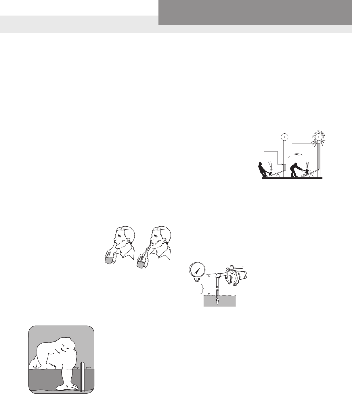
PAGE 50
Residential Water Systems
Goulds Water Technology,
Bell & Gossett, Red Jacket Series, CentriPro
2 WELL CONDITIONS
The level of the water to be
pumpedispracticallyalwaysbe-
lowground.Itcanbeonlyafew
feetasinaspring,shallowwell,
pond,etc.,oritcanbemanyfeet
as in a deep well. If we could
alwayslocatethepumping
mechanisminthewater,aswe
dowithsubmersiblepumps,
our problem would be simpler
because then the water would
owintothepump.However,
standard electric motors and
switches are not designed for
submerged operation. Therefore
theymustbelocatedabove
ground.Thisposesthequestion:
Howdoesthewatergetintothe
pump?
Wecallitsuction,butwhatisit?
Whatactuallymakesthewater
owuphillintothepump?
Howhighcanweraisewaterby
suction?
1. The atmosphere all around us
has weight and therefore ex-
erts pressure equal to about
14.7 lbs. per square inch at
sea level. When the pressure
of atmosphere is removed
from inside of a pump the re-
sulting condition is a vacuum
or partial vacuum. It is also
called suction.
The vacuum or suction
chamber of a pump is piped
(suction pipe) to a source
of water. The surface of the
water should be exposed to
the pressure of atmosphere.
When the pump operates
it develops an unbalanced
pressure condition due to
the suction or vacuum it
produces. This unbalanced
pressure (14.7 lbs. per sq.
in. atmospheric pressure
on the surface of the water
with vacuum or absence of
pressure in the pump) causes
water from the source to
owupthesuctionpipeinto
the pump. From this we can
determine how high water
canberaisedbysuction.
First,let’sconsidertermsof
measurement and their relation
to each other.
Pressureisusuallyexpressedin
poundspersquareinch(PSI).
Pressureisusedtoraisewaterto
a height expressed in feet. This
height is also expressed as feet
head.
Vacuumismeasuredwitha
vacuum gauge. The gauge can
be calibrated in feet suction lift
or inches vacuum.
A. 1 inch vacuum equals
1.13 feet suction.
B. 1 pound pressure
equals 2.31 feet head.
C. Atmospheric pressure
of14.7x2.31=33.9ft.head,
which is the maximum pos-
sible lift at sea level.
Atmospheric
Pressure
14.7 LBS.
Water Level
Atmospheric Pressure
Try to lift soda from a bottle by
closing your mouth over the
mouth of the bottle. It can’t be
done. When you use a straw,
it is easy – you are creating a
partial vacuum in your mouth,
exposing the surface liquid
to atmospheric pressure, the
difference in pressure raises
the liquid.
NOTE:Youloseapproximately
one foot of suction lift per 1000
ft. of elevation.
Example:Denver,COisap-
proximately5000ft.abovesea
level. The total suction lift would
onlybe28.9ft.not33.9ft.like
at sea level.
Vacuum
Gauge
22.6'
VERTICAL LIFT
PLUS FRICTION
A. 20
A reading of 20" on a vacuum
gauge placed on a suction side
of the pump would tell you that
you had a vacuum or suction
lift of 22.6 ft.
20" x 1.13' = 22.6 ft.
14.7 lbs.1 lb.
2.31 ft.
B. C.
14.7 lbs.
2.31 ft.
33.9 ft.
X
G
O
N
G
!
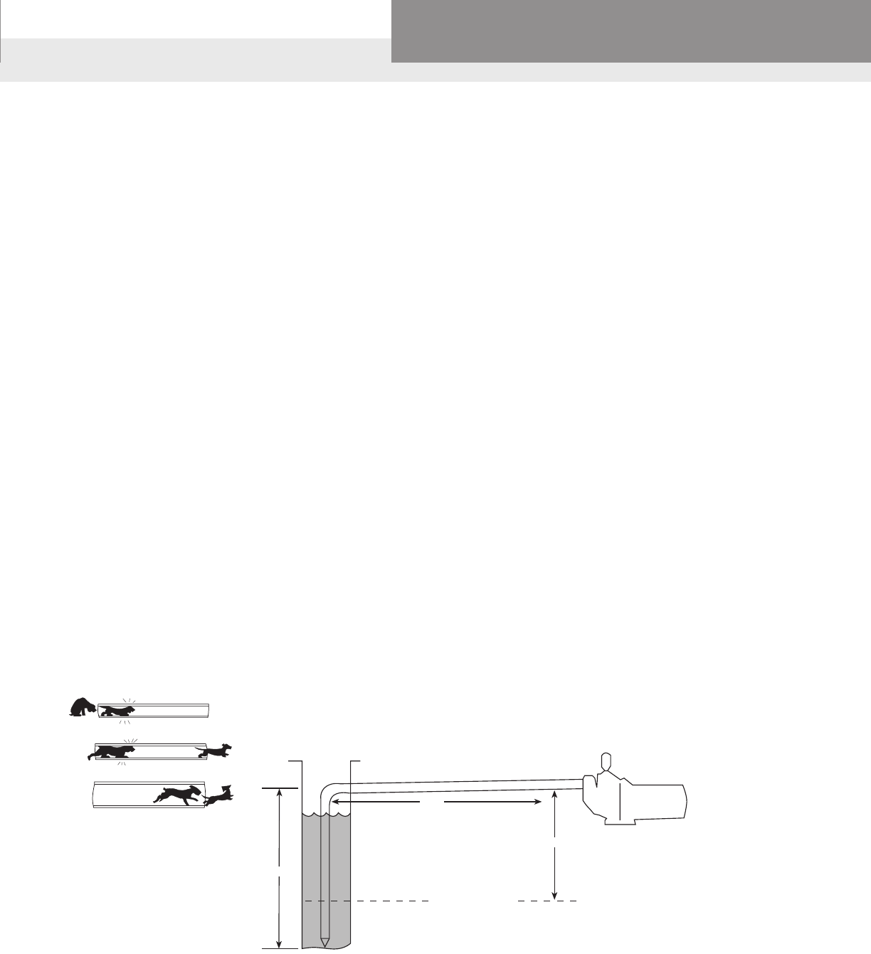
PAGE 51
Residential Water Systems
Goulds Water Technology,
Bell & Gossett, Red Jacket Series, CentriPro
SUMMING THIS UP:
When the atmospheric pressure
is 14.7 lbs. per sq. inch a perfect
vacuum should be 30 inches
andthiswouldliftwaterbysuc-
tion to a height of 33.9 ft.
Mostshallowwellorsuction
pumps are capable of develop-
inganearperfectvacuum,and
atsealeveltheycanliftwater
aboutthirtyfeet.However,suc-
tion lifts of more than 25 ft. at
sea level are not recommended.
Shallow well jet pumps deliver
inadequatecapacityonliftsover
25 ft.
Suctionconditions,ortotal
suction lift must include all
resistancestotheowofthe
water through the suction pipe
uptothepump.Heightorverti-
cal lift is one resistance. Friction
between the water and the pipe
walls is the other resistance.
FRICTION LOSS
Whenwaterowsthroughpipe,
the inner wall of the pipe resists
theowofthewater.Thisresis-
tance is called pipe friction.
Pipefrictionmeansextrawork
forthepumporsystemand
presentsatotalloss.Therefore,
it is desirable to keep friction
loss as low as is practicable in
order to waste the least possible
amount of work. Keep in mind
that all work being done on
the suction side of the pump
isactuallyperformedbythe
pressure of atmosphere. Since
in common practice we consider
thispressureissufcientto
overcomeonly25ft.,the25ft.
mustalwaysincludeanylosses
due to friction.
Wedon’thavetobetoocon-
cernedwithhoworwhyfriction
lossisincurred,butitisessential
that we accept it as occurring al-
wayswhenwaterowsthrough
pipes.Itis,also,mostessential
that we understand how it is
measured.
Inourdiscussionofsuctionlift,
atmospheric pressure and the
height this pressure will raise
water,weestablishedthefact
that 14.7 lb. pressure will raise
water to a height of 33.9 ft.
Although there is no relation
between atmospheric pressure
andfrictionloss,therelation
between pounds pressure and
feet elevation or head as we call
it,isthesamewhetherthepres-
sure is coming from atmosphere
oranyothersource.So,asstated
before,14.7lbs.pressurefrom
anysourcewillraisewater33.9
ft. and this gives us the conver-
sion factor to change our terms
from pressure to feet or the
reverseofthis.Therefore,1lb.of
pressureisalwaysequalto2.31
ft.(33.9dividedby14.7equals
2.31).
Nowgettingbacktofrictionloss,
the amount of this loss increases
asthequantityofwaterowing
throughagivensizepipeis
increased. There are formulas to
determinetheamountofow
andanypipesize.Butwedon’t
havetobeconcernedwiththis,
sinceithasallbeencarefullycal-
culated and set up in the friction
loss table as shown below.
PUMPING LEVEL
OF WATER
23 ft.
STATIC LEVEL OF WATER
TOTAL LENGTH OF SUCTION PIPE IS 100’ CAPACTIY OF PUMP IS
7 GALLONS PER MINUTE
VERTICAL LIFT (ELEVATION) = 23' . . . . . . . . . 23'
FRICTION OF 7 GPM
IN 100 FT. OF PIPE 1" = 3.56' 11⁄4" = .93'
TOTAL SUCTION LIFT = 26.56' . . . . . . . . . 24'
OBVIOUSLY 11⁄4" PIPE MUST BE USED.
25 ft.
75 ft.
Friction Loss Increases
when Capacity Increases
or Pipe Length Increases
Example: The example at the
top of the page shows that using
thecorrectsizepipewillreduce
frictionloss.Onsomejobs,a
smaller pump with larger pipe
willdothesamework(ow)asa
larger pump with smaller pipe.
Larger pipe is not much more
expensive but larger pumps are.
Larger pumps also use more
energy.Usingthecorrectpipe
sizesavesmoneyinthelong
run. Calculating friction loss is
especiallyimportantifyouare
not sure of the well drawdown.
Itisaverygoodruleofthumbto
alwaysuseasuctionpipethatis
thesamesizeorlargerthanthe
pump suction.
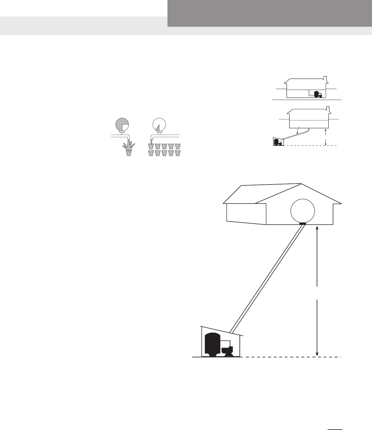
PAGE 52
Residential Water Systems
Goulds Water Technology,
Bell & Gossett, Red Jacket Series, CentriPro
3 DISCHARGE CONDITIONS
What are the conditions under
whichthewatersystemmust
dischargeitscapacity?
Thecapacityofthepumphas
alreadybeenestablishedsowe
arenowconcernedonlywiththe
pressurerequiredofthesystem.
It seems that the pressure and
its use in a domestic water
systemaregenerallymisun-
derstood,soperhapssome
explanation is in order. Quite
often it is stated that a particular
pumpisdeliveringsufcient
capacitybutfailstodevelopad-
equate pressure. In most cases
this is a misstatement and the
opposite condition is true. This
complaintisgenerallymade
whenaparticularsystemfailsto
providesufcientowthrough
several outlets at the same time.
This is caused in most cases
bythedemandinrateofow
beinggreaterthanthecapacity
ofthesystem.Ifthesystemhas
sufcientcapacitytosupplythe
maximum number of outlets
whicharelikelytobeusedat
thesametime,ouronlyconcern
with pressure is that we have
sufcientpressuretoovercome
theresistancetoowwhichwill
beencountered.Ifyouhaveany
doubtsaboutthis,consideryour
answertothisquestion:
Wouldyouratherhaveata
faucet one gallon per minute at
a hundred pounds pressure or
ten gallons per minute at ten
poundspressure?Whichwillll
atubquicker?
Nowastotheresistancetoow
whichwillbeencountered,there
are three causes. These are (1)
theresistancebytheoutletitself
suchasapartiallyrustedshower
head,(2)frictionlossinpipe
lines,and(3)thatresistancedue
to difference in elevations.
Actuallynoneofthesewillhave
to be computed in most applica-
tionsbecauseusuallythepump
isinstalledatthehouse,andthe
standard pressure range of the
systemissufcienttoovercome
these resistances and deliver its
capacitytothevariousoutlets.
An example in which these
computations must be made
iswhenthepumporsystemis
located at considerable distance
from the point of use and on a
lower elevation.
In such a case the difference in
elevation must be determined
(1lb.Pressureisnecessaryto
overcome each 2.3 ft. elevation);
the friction loss in feet calculated
and changed to pounds pressure
(againthesamerelation,1lb.
Pressureequals2.3ft.orthiscan
bereaddirectlyfromthetable
in lbs.); the service pressure or
pressure required at the faucet
must be decided; the total of
these three will be the discharge
conditions or operating pressure
required of the pump.
Example
Service pressure desired – 30 lbs. minimum ...............................30 lbs.
Elevation 23 ft.
1 lb. = 2.3 ft.
23 ft. / 2.3 ft. = 10 lbs. .................................................................10 lbs.
Friction:
Pump capacity is 7 GPM
This ow through 200 ft. of 1" pipe
gives a friction loss of 3.06 lbs. ....................................................... 3 lbs.
43 lbs.
Pressure switch setting at the pump would be (43-63 lbs.)
PSI PRESSURE
1 GALLON
PER MINUTE
PSI
100 10
10 GALLONS
PER MINUTE
FRICTION LOSS?
ELEVATION?
UNUSUAL CONDITION
NO PROBLEM
AVERAGE CONDITIONS
This means when the
pressure switch cuts the
pump on at about 43 lbs.
Tank pressure, the pres-
sure at the house will
be 30 lbs. When the
water is owing at
a rate of 7 gallons
per minute.
30
PSI
200'
1" PIPE
23'
ELEVATION
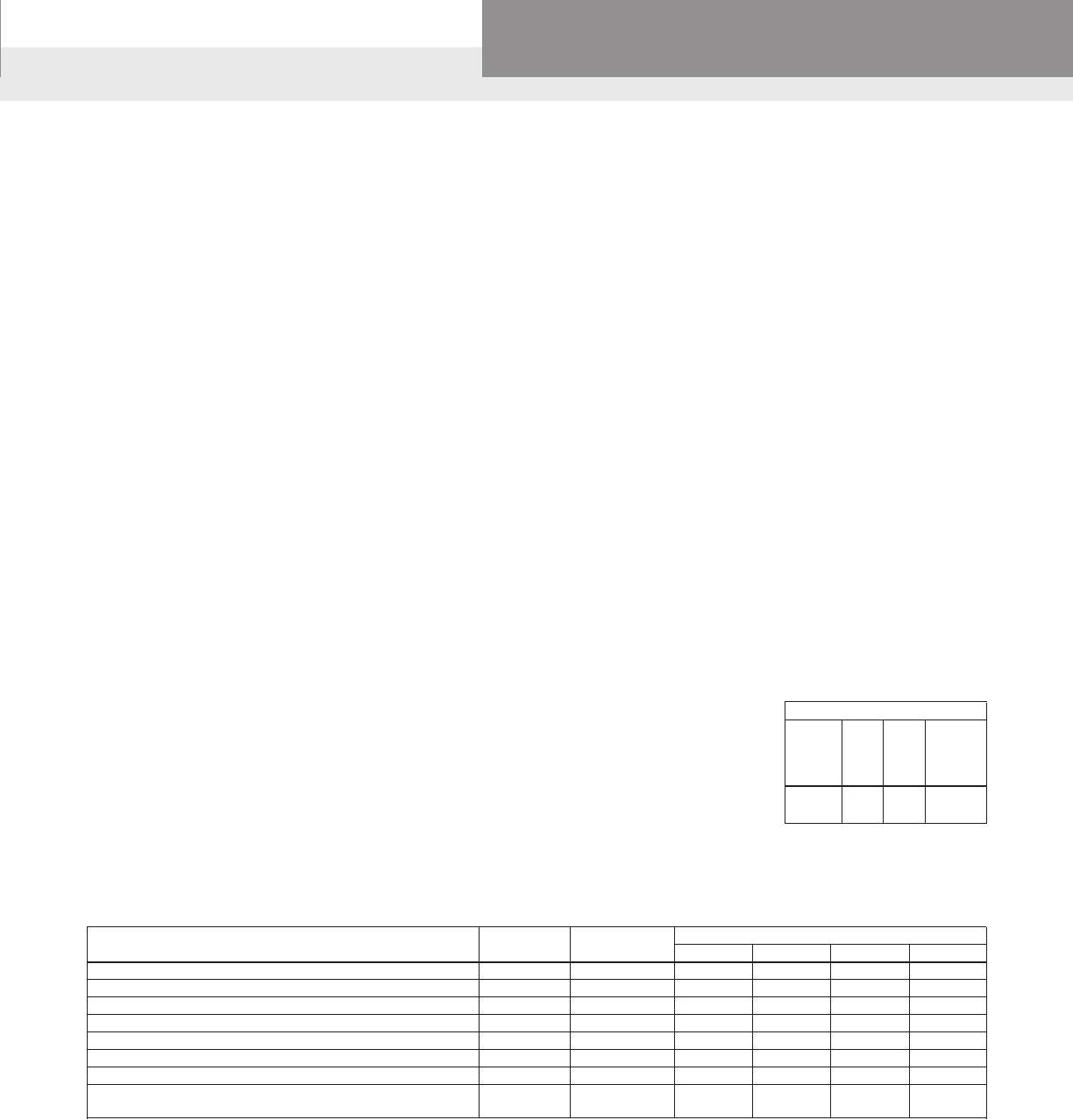
PAGE 53
Residential Water Systems
Goulds Water Technology,
Bell & Gossett, Red Jacket Series, CentriPro
SUMMARY
Now let’s summarize briey
the points we’ve covered.
We have shown that in a
water system application,
there are three factors to
consider:
1. Water Needed or
Determination of Capacity
2. Suction Conditions, and
3. Discharge Conditions.
We have concluded that
capacity required is deter-
mined by the maximum
number of outlets which will
be in continuous use
at the same time with a mini-
mum ow of three gallons
per minute per outlet.
We have shown that all jet
pumps, whether shallow
well or deep well, have a
water end in which there is
a suction chamber; that the
suction chamber is actu-
ally a closed container in
which a partial vacuum is
created. This allows atmo-
spheric pressure to force
in the water. The suction
chamber must be located
within about 25 feet vertical
distance above the pump-
ing level of the water.
The main difference
between shallow well and
deep well pumps is that in
the former the water end is
built onto the power end.
The water end of deep well
jet pumps is a separate part.
It is installed in the water
and is used to pump water
from levels below a 25 feet
depth. We have shown that
a submersible should be
used when source will allow.
Since the submersible is
submerged in water only
discharge conditions apply.
We’ve established three
distinct forms of resistance
to ow encountered as
Discharge Conditions and
shown that they must be
considered but computed
only in special cases. Also,
that the pump is only part
of the system necessary
to provide an automatic
service. Other accessories
are necessary and we’ve
established the need and
function of each of these
accessories.
We have mentioned 3 GPM
as a minimum acceptable
ow rate per outlet. But
a larger ow rate is more
desirable and the following
table should be used as an
average supply required
when the source of supply
will allow it.
We would like to leave you
with one thought. That is,
capacity and pressure are
inversely related. When one
goes up, the other goes
down. Always check the rat-
ing chart or curve of a pump
to make sure if you raise the
pressure you will still receive
the needed supply of water
at your outlets.
Using the rating chart below,
we would be getting 8 GPM
from the pump at 20 lbs.
pressure. If we were trying to
supply two outlets at once,
this would give us approxi-
mately 4 GPM at each one.
If we increase the pressure
to 30 lbs. pressure, we only
get 6 GPM which will give
us approximately 3 GPM at
each outlet. By raising the
pressure we have reduced
the amount of water at each
outlet by approximately
25%.
Always check the pump
performance rating before
making a change.
Seven Minute Peak Demand Period Usage
Outlets Flow Rate Total Usage Bathrooms In Home
GPM Gallons 1 1½ 2-2½ 3-4
Shower or Bath Tub 5 35 35 35 53 70
Lavatory 4 2 2 4 6 8
Toilet 4 5 5 10 15 20
Kitchen Sink 5 3 3 3 3 3
Automatic Washer 5 35 – 18 18 18
Dishwasher 2 14 – – 3 3
Normal seven minute*peak demand (gallons) 45 70 98 122
Minimum sized pump required to meet peak 7 GPM 10 GPM 14 GPM 17 GPM
demand without supplemental supply (420) (600) (840) (1020)
Note: Values given are average and do not include higher or lower extremes.
*Peak demand can occur several times during morning and evening hours.
Additional Requirements: Farm, irrigation and sprinkling requirements are not shown. These values must be added to the peak demand
gures if usage will occur during normal demand periods.
Performance Rating in
Gallons per Minute
Pump Discharge Pressure
Total Max.
Suction 20 30 Shut-
Lift PSI PSI Off
in Lbs.
5 feet 8 6 51 lbs.
GPM GPM

Xylem Inc.
2881 East Bayard Street Ext., Suite A
Seneca Falls, NY 13148
Phone: (866) 325-4210
Fax: (888) 322-5877
www.xyleminc.com
Goulds is a registered trademark of Goulds Pumps, Inc. and is
used under license. Bell & Gossett, Red Jacket Water Products and
CentriPro are trademarks of Xylem Inc. or one of its subsidiaries.
© 2017 Xylem Inc. TTECHWP R3 February 2017
1) The tissue in plants that brings water upward from the roots;
2) a leading global water technology company.
We’re a global team unied in a common purpose: creating advanced technology
solutions to the world’s water challenges. Developing new technologies that will
improve the way water is used, conserved, and re-used in the future is central to our
work. Our products and services move, treat, analyze, monitor and return water to the
environment, in public utility, industrial, residential and commercial building services,
and agricultural settings. With its October 2016 acquisition of Sensus, Xylem added
smart metering, network technologies and advanced data analytics for water, gas
and electric utilities to its portfolio of solutions. In more than 150 countries, we have
strong, long-standing relationships with customers who know us for our powerful
combination of leading product brands and applications expertise with a strong
focus on developing comprehensive, sustainable solutions.
For more information on how Xylem can help you, go to www.xyleminc.com
Xylem
