551692 1 Grundfos SQ Series Brochure
: Pump 551692 1 Grundfos Sq Series Brochure 551692_1_Grundfos SQ Series Brochure pdf
Open the PDF directly: View PDF ![]() .
.
Page Count: 64
- 1. Product introduction
- 2. Applications
- SQ with pressure switch and pressure tank
- Constant-pressure control with CU 301 - residential water supply
- Constant-pressure control with CU 301 - irrigation
- Maintaining a constant water table
- Emptying or filling a tank
- Pumping from one tank to another
- Setting of operating parameters
- SQE with manual speed control
- 3. Performance range
- 4. Installation
- 5. Sizing and selection
- 6. Cable sizing
- 7. SQ curve charts
- 8. Technical data
- 9. Construction
- 10. Control units
- 11. CU331SP variable frequency drive
- 12. Accessories
- 13. Further product documentation
GRUNDFOS DATA BOOKLET
SQ, SQE, SQE-NE,
CU331SP

Table of contents
2
SQ, SQE, SQE-NE,
CU331SP
1. Product introduction 3
Features and benefits 3
Identification 5
2. Applications 6
SQ with pressure switch and pressure tank 6
Constant-pressure control with
CU 301 - residential water supply 7
Constant-pressure control with
CU 301 - irrigation 8
Maintaining a constant water table 9
Emptying or filling a tank 10
Pumping from one tank to another 11
Setting of operating parameters 12
SQE with manual speed control 13
3. Performance range 14
4. Installation 15
5. Sizing and selection 16
System sizing guide 16
6. Cable sizing 17
Cable sizing chart 17
7. SQ curve charts 18
5 SQ, SQE 18
10 SQ, SQE 19
15 SQ, SQE 20
22 SQ, SQE 21
30 SQ, SQE 22
10 SQE-NE 23
22 SQE-NE 24
8. Technical data 25
Electrical data 25
Operating conditions 25
Motor data 26
Dimensions and weights 27
9. Construction 28
Materials of construction 28
Material specification 29
10. Control units 30
CU 301 30
CU 300 33
11. CU331SP variable frequency drive 37
Features 37
Applications 37
System components 37
Identification 38
CU331SP product range 39
CU331SP performance range 39
CU331SP sizing 39
CU331SP operation 40
CU331SP installation 44
CU331SP electrical connection 45
CU331SP technical data 51
CU331SP curve charts 53
12. Accessories 59
CU331SP Constant Pressure
Drive Kits (with sensor) 59
CU 301 Constant Pressure System 59
CU 300 Status Box & R100 59
SQ, SQE flow sleeves 59
13. Further product documentation 60
WebCAPS 60
WinCAPS 61
Product introduction
SQ, SQE, SQE-NE,
CU331SP 1
3
1. Product introduction
3-inch SQ, SQE submersible well pumps for 3-inch
and larger wells
SQ, SQE pumps are suitable for both continuous and
intermittent operation for a variety of applications:
• Domestic water supply
• light commercial
• irrigation
• tank applications.
Features and benefits
SQ, SQE pumps offer these features:
• Dry-run protection
• high efficiency pump and motor
• protection against up-thrust
•soft-start
• over-voltage and under-voltage protection
• over-temperature protection
• high starting torque.
Additionally, SQE pumps offer these advantages:
• Constant pressure control
• variable speed
• electronic control and communication.
SQ, SQE innovative motor technology
SQ, SQE pumps feature an innovative motor design
incorporating permanent-magnet technology. By
combining permanent-magnet motors and a Grundfos
micro-frequency converter, we are able to deliver
unmatched performance and the ability to control and
communicate with the pump in ways never before
possible. A few of the features that result from this
combined technology are Constant Pressure Control,
Soft-Start, and Integrated Dry-Run Protection, but
these are just a few of the features these pumps offer.
SQ pump models operate at a constant speed much
like today’s conventional pumps. The difference is that
SQ delivers the benefits of an electronically controlled
permanent-magnet motor that cannot be achieved with
a conventional induction motor.
SQ pumps are available for single-phase power; a
simple 2-wire design makes installation easy.
SQE pumps are equipped with a Grundfos "Smart
Motor." Like the SQ models, SQ pumps have a high
efficiency permanent-magnet motor — but we add the
ability to communicate.
The "Smart Motor" communicates via the CU301
status box through the power leads.
It is not necessary to run any additional wires down the
well. Communication with the pump provides Constant
Pressure Control and the highly useful ability to
change the pump performance while the pump is
installed in the well. Like the SQ motor, this is also a 2-
wire motor designed for single-phase operation.
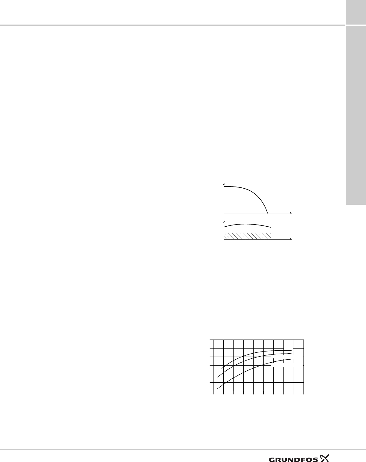
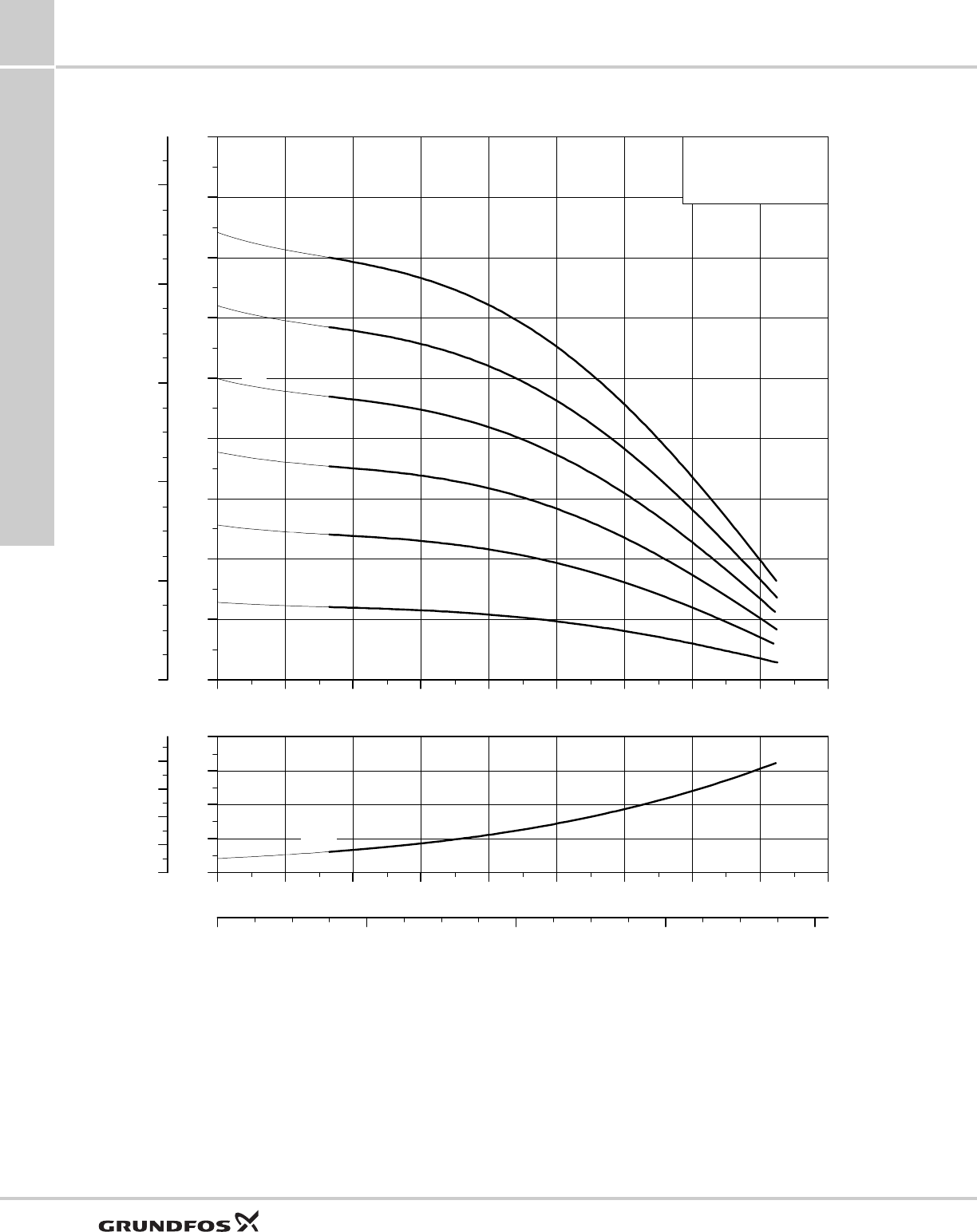
Dry-running protection
The pumps are protected against dry running. A value
of Pcut-out ensures cut-out of the pump in case of lack
of water in the borehole thus preventing a burnout of
the motor.
Pcut-out is factory-set both for the SQ and SQE, SQE-
NE pumps.
Fig. 1 Pcut-out curve
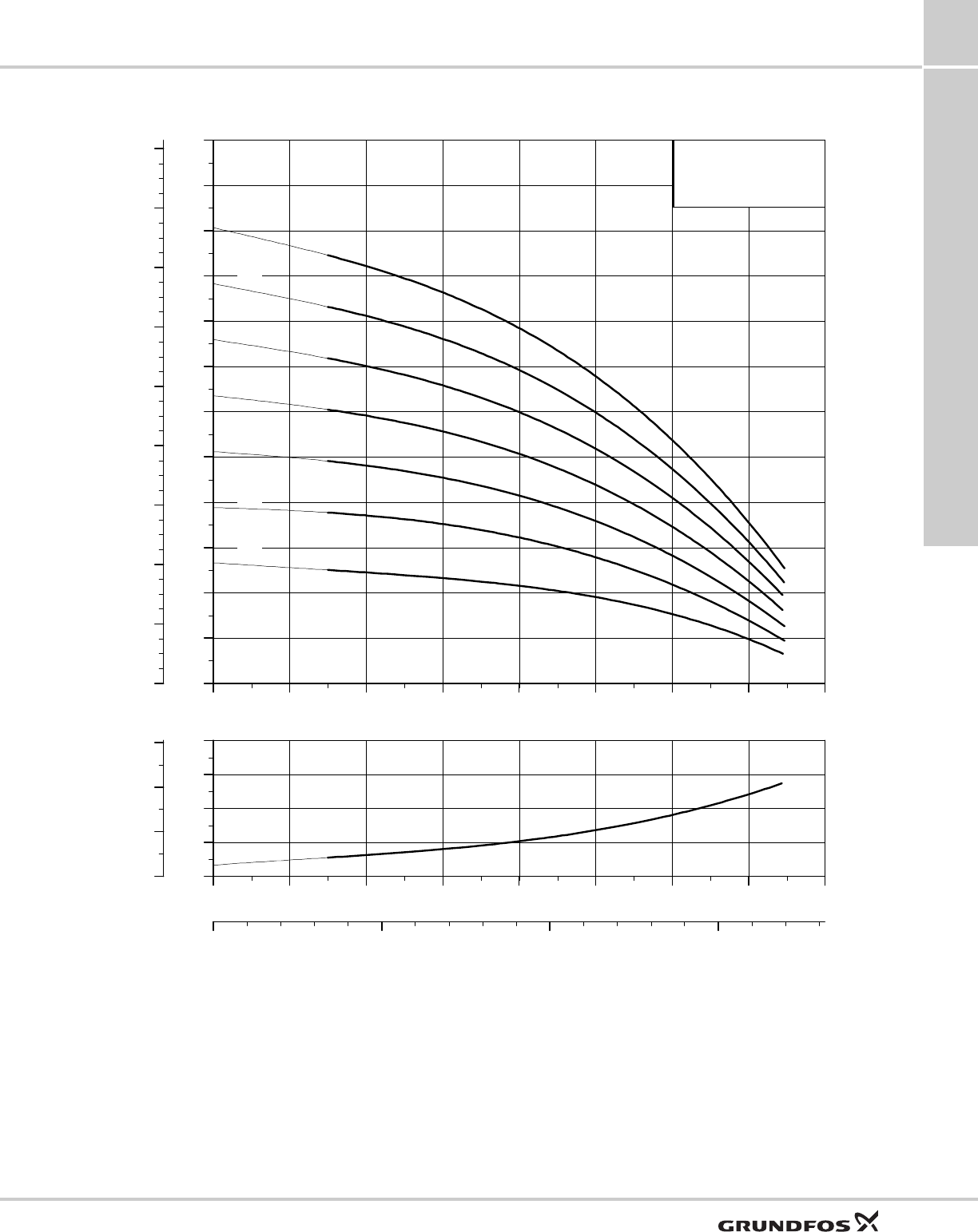
High pump efficiency
The hydraulic pump components are polyamide
reinforced with 30 % glass fiber. The hydraulic design
provides for high pump efficiency resulting in low
energy consumption and therefore low energy costs.
High motor efficiency
The motors are based on a permanent magnet rotor
(PM motor) featuring high efficiency within a wide load
range.
Fig. 2 Efficiency curves of Grundfos SQ motor
versus conventional motors
TM01 2751 2298TM01 2698 2298
H
Q
cut-out
P
Q
P1
P
cut-out
200 250 300 350 400 450 500 550 P2 [W]
45
50
55
60
65
70
[%]
Eta
Conventional 1 ph
Conventional 3 ph
MS 3
Conventional 3-ph.
Conventional 1-ph.
SQ.
Product introduction
SQ, SQE, SQE-NE,
CU331SP
1
4
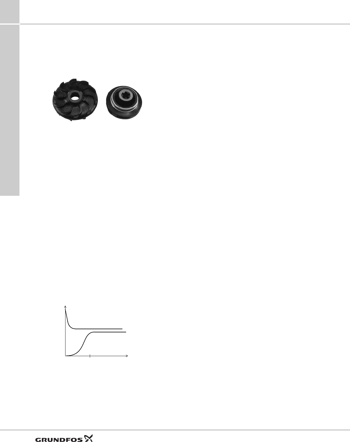
Wear resistance
The pump design features "floating" impellers (not
fastened to the shaft). Each impeller has its own
tungsten carbide/ceramic bearing. The construction
and materials ensure high wear resistance to sand for
long product life.
Fig. 3 Example of Grundfos floating impeller
Protection against upthrust
Starting up a pump with a very low counter pressure
involves the risk of the entire impeller stack being
lifted, also called upthrust. Upthrust may cause
breakdown of both pump and motor.
SQ, SQE, SQE-NE motors are fitted with a top bearing
protecting both pump and motor against upthrust, thus
preventing breakdown during the critical start-up
phase.
Excellent starting capabilities
The integrated electronic unit of the motor features soft
starting. Soft start reduces the starting current and
thus gives the pump a smooth and steady
acceleration.
The soft starter minimizes the risk of wear on the pump
and prevents overloading of the mains during start-up.
The excellent starting capabilities are a result of the
high locked-rotor torque of the permanent magnet
motor together with the few pump stages. The high
starting reliability also applies in case of low voltage
supply.
Fig. 4 Soft-start feature
Overvoltage and undervoltage protection
Overvoltage and undervoltage may occur in case of
unstable voltage supply.
The integrated protection of all motors prevents
damage to the motor in case the voltage moves
outside the permissible voltage range.
The pump will cut out if the voltage falls below 150 V or
rises above 315 V. The motor is automatically cut in
again when the voltage again falls within the
permissible voltage range. Therefore no extra
protection relay is needed.
Overload protection
Exposure of the pump to heavy load causes the
current consumption to rise. The motor will
automatically compensate for this by reducing the
speed to 3000 rpm. Further overload will lead to stop.
If the rotor is being prevented from rotating, this will
automatically be detected and the power supply will be
cut out. Consequently, no extra motor protection is
needed.
Overtemperature protection
A permanent magnet motor gives off very little heat to
its surroundings. In combination with an efficient
internal circulation system leading the heat away from
the rotor, stator and bearings, this ensures optimum
operating conditions for the motor.
As an extra protection, the electronic unit has a built-in
temperature sensor. When the temperature rises too
high, the motor is cut out; when the temperature has
dropped, the motor is automatically cut in again.
Reliability
The motors are built for high reliability and feature:
• Tungsten carbide / ceramic bearings
• thrust bearings protecting against downthrust
• product life time equal to conventional AC motors.
Variable speed
The SQE motor enables continuously variable speed
control from 3,000 to 10,700 rpm. The pump can be set
to operate in any duty point in the range between the
3,000 and 10,700 rpm performance curves of the
pump. Consequently, the pump performance can be
adapted to any specific requirement.
The variable speed control facility requires the use of
the CU 300 or CU 301 control unit.
For the calculation of pump speed, the program
"SQE Speed Calculation" is available on CD-ROM as
an accessory.
TM01 3141 3498TM01 3479 4198
Current [A]
DOL (direct-on-line starting)
Soft start
3Time [s]

Product introduction
SQ, SQE, SQE-NE,
CU331SP 1
5
Identification
Type key example SQ, SQE, SQE-NE
10 SQ E 05 - 160 N E
Rated gallons per minute
Basic version (without
communication)
Electronic communication
Horsepower
Total Dynamic Head in (ft) at rated flow
Stainless steel 316
Environmental, PVDF impellers
Applications
SQ, SQE, SQE-NE,
CU331SP
2
6
2. Applications
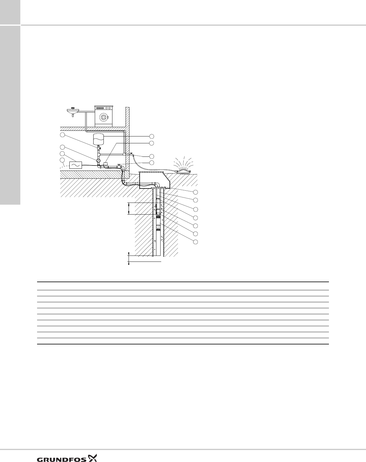
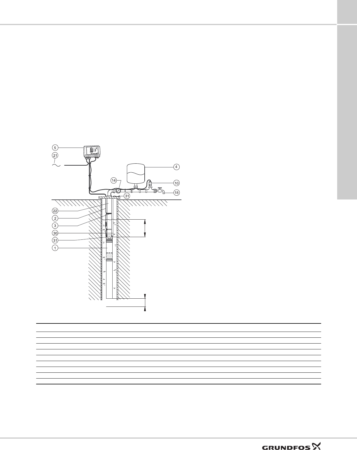
SQ with pressure switch and pressure tank
SQ is ideally suited for domestic water supply in
single- family dwellings or summer homes which are
not connected to municipal waterworks. SQ is easy to
install and operate.
Fig. 5 Application example: SQ with pressure switch and pressure tank
TM01 2447 1798
Pos. Part Type No. of units Product number Unit price Total price
1Pump SQ
2 Cable
3 Cable clips
4 Pressure tank
12 Pressure switch
14 Pressure gauge
20 Mains switch
30 Safety cable
31 Wire clamp
17
14
22
2
3
4
12
18
20
21 17
31
30
31
1
1 Pump, SQ
2 Cable
3 Cable clips
4 Pressure tank
12 Pressure switch
14 Pressure gauge
17 Isolating valve
18 Tap
20 Mains switch
21 Mains connection
22 Riser pipe
30 Safety cable
31 Wire clamp
Recommended min.
20 inches (0.5 m)
Min. 20 inches
(0.5 m)
Applications
SQ, SQE, SQE-NE,
CU331SP 2
7
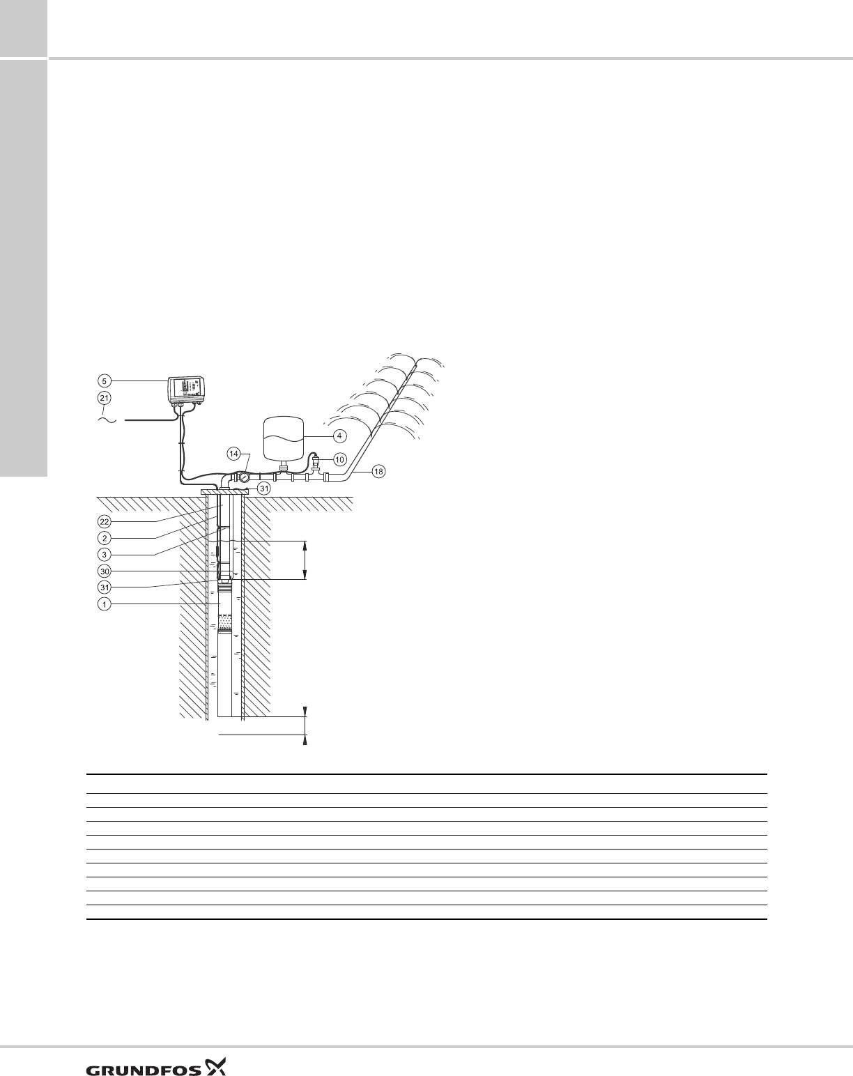
Constant-pressure control with
CU 301 - residential water supply
The system maintains a constant pressure within the
maximum pump performance in spite of a varying
water consumption.
The pressure is registered by the pressure sensor and
transmitted to the CU 301. The CU 301 adjusts the
pump performance accordingly.
Function
When a tap is opened the pressure in the tank will start
to drop. At a flow lower than approximately 1 gpm
(0.18 m3/h), the pressure will drop slowly.
When the pressure in the tank is 7 psi (0.5 bar) below
setpoint, the pump will start. The pump will run until the
pressure is 7 psi (0.5 bar) above setpoint. This way of
operation is called on/off operation.
At a flow higher than approximately 1 gpm (0.18 m3/h),
the pressure will drop quickly and the pump will start
immediately and maintain a constant pressure.
During operation, the CU 301 will regulate the pump
speed to maintain a constant pressure. If there is no
consumption, the pump will boost the pressure to 7 psi
(0.5 bar) above setpoint and stop after a few seconds.
Fig. 6 Application example: Constant-pressure control with CU 301 - residential water supply
TM03 3429 0406
Pos. Part Type No. of units Product number Unit price Total price
1Pump SQE
2 Cable
3 Cable clips
4 Pressure tank 2 gal (8 liters)
5 Control unit CU 301
10 Pressure sensor 0 - 120 psi (0 - 6 bar)
14 Pressure gauge
30 Safety cable
31 Wire clamp
Recommended min.
20 inches (0.5 m)
Min. 20 inches
(0.5 m)
1Pump, SQE
2Cable
3Cable clips
4 Pressure tank, 2 gal (8 liters)
5 Control unit, CU 301
10 Pressure sensor, 0 - 120 psi (0 - 6 bar)
14 Pressure gauge
18 Tap
21 Mains connection
22 Riser pipe
30 Safety cable
31 Wire clamp
Applications
SQ, SQE, SQE-NE,
CU331SP
2
8
Constant-pressure control with
CU 301 - irrigation
The system maintains a constant pressure within the
maximum pump performance in spite of a varying
water consumption.
The pressure is registered by means of the pressure
sensor and transmitted to the CU 301. The CU 301
adjusts the pump performance accordingly.
Function
When the sprinkler system is started, the pressure in
the tank will start to drop.
At a flow lower than approximately 1 gpm (0.18 m3/h),
the pressure will drop slowly. When the pressure in the
tank is 7 psi (0.5 bar) below setpoint, the pump will
start. The pump will run until the pressure is 7 psi (0.5
bar) above setpoint. This way of operation is called
on/off operation.
At a flow higher than approximately 1 gpm (0.18 m3/h),
the pressure will drop quickly and the pump will start
immediately and maintain a constant pressure.
During operation, the CU 301 will regulate the pump
speed to maintain a constant pressure. If there is no
consumption, the pump will boost the pressure to 7 psi
(0.5 bar) above setpoint and stop after a few seconds.
Fig. 7 Application example: Constant-pressure control with CU 301 - irrigation
TM03 3428 2810
Pos. Part Type No. of units Product number Unit price Total price
1Pump SQE
2 Cable
3 Cable clips
4 Pressure tank 2 gal (8 liter)
5 Control unit CU 301
10 Pressure sensor 0 - 120 psi (0 - 6 bar)
14 Pressure gauge
30 Safety cable
31 Wire clamp
Min. 20 inches
(0.5 m)
Recommended min.
20 inches (0.5 m)
1 Pump, SQE
2 Cable
3 Cable clips
4 Pressure tank 2 gal (8 liter)
5 Control unit, CU 301
10 Pressure sensor, 0 - 120 psi (0-6 bar)
14 Pressure gauge
18 Sprinkler system
21 Mains connection
22 Riser pipe
30 Safety cable
31 Wire clamp
Applications
SQ, SQE, SQE-NE,
CU331SP 2
9
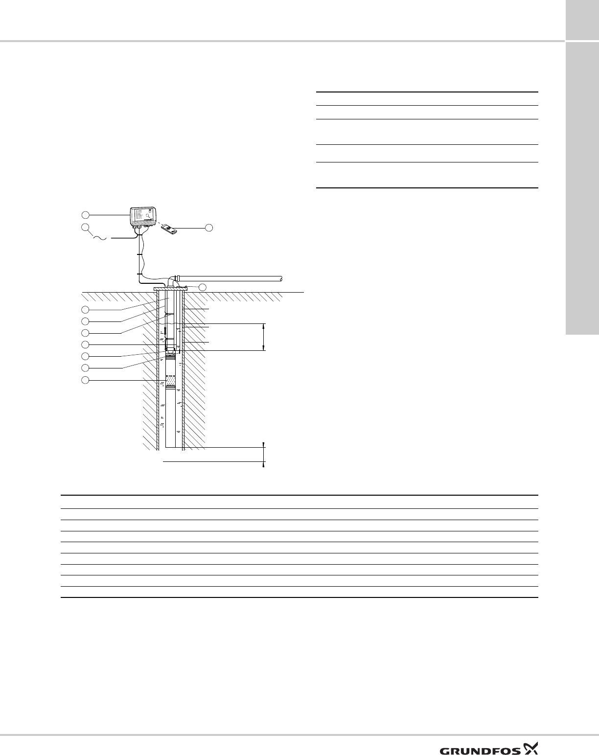
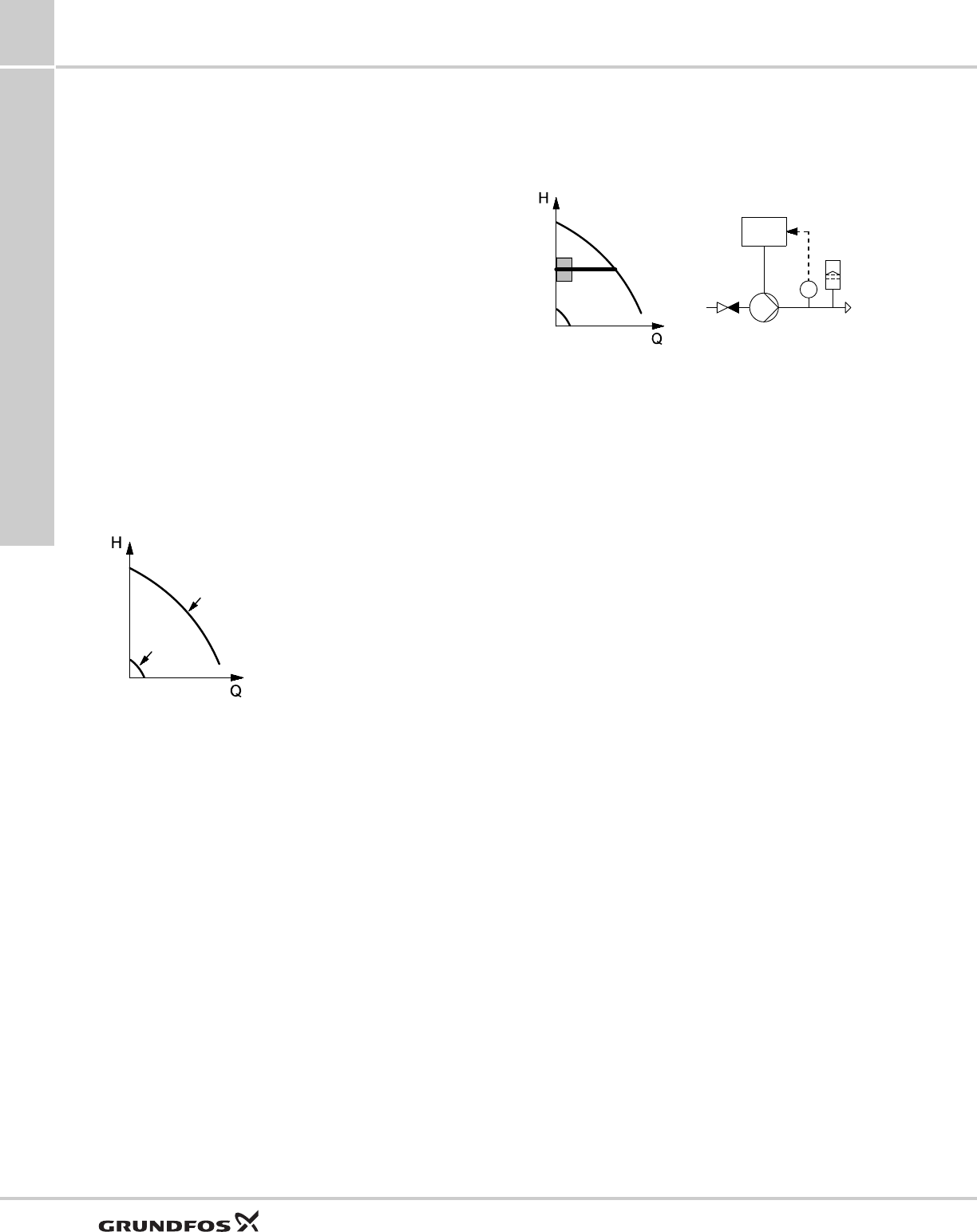
Maintaining a constant water table
A constant water table can be maintained by adjusting
pump performance. It may be important to maintain a
constant water table, e.g. in connection with keeping
out the groundwater on a building site or water
remediation projects.
The example shows how to maintain a constant water
table by adjusting pump performance.
Sensors
Fig. 8 Application example: Maintaining a constant water table
Level Description Reaction
Level sensor (pos. 11)
Warning (max.)
Too high water level.
Possible cause: Insufficient
pump capacity.
Alarm relay
operates.
Desired level The water level which should
be maintained.
Warning (min.)
Too low water level.
Possible cause: Too high
pump capacity.
Alarm relay
operates.
TM01 2459 2810
22
31
2
3
30
31
11
R100
5
21 29
1
1 Pump, SQE
2 Cable
3 Cable clips
5 Control unit, CU 300
11 Level sensor
21 Mains connection
22 Riser pipe
29 Remote control, R100
30 Safety cable
31 Wire clamp
R100
Warning (max.)
Desired level
Warning (min.) Recommended min. 20 inches (0.5 m)
Min. 0.5 m
Pos. Part Type No. of units Product number Unit price Total price
1Pump SQE
2 Cable
3 Cable clips
5 Control unit CU 300
11 Level sensor
29 Remote control R100
30 Safety cable
31 Wire clamp
Applications
SQ, SQE, SQE-NE,
CU331SP
2
10
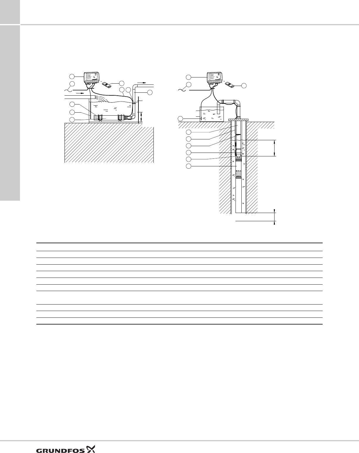
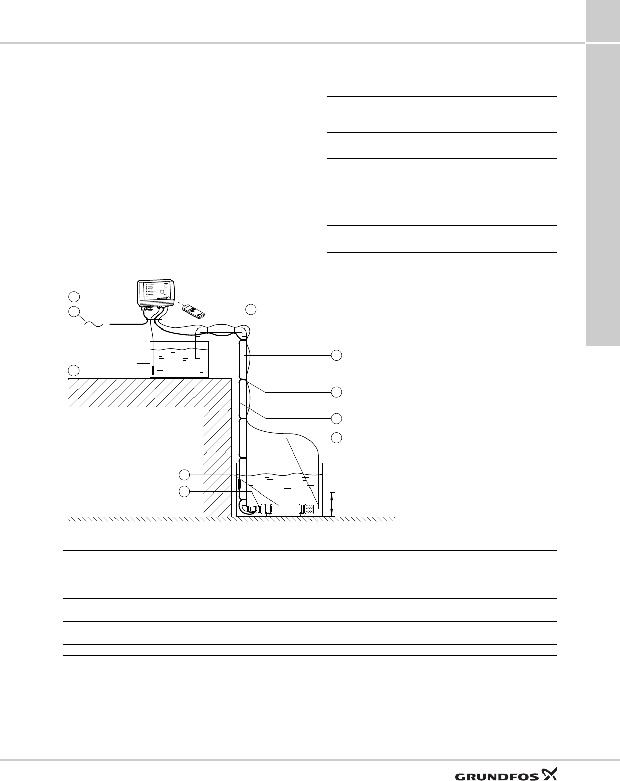
Emptying or filling a tank
The SQE pump with CU 300 is ideal for emptying or
filling a tank.
Fig. 9 Application example: Emptying or filling a tank
TM01 8649 4801
Pos. Part Type No. of units Product number Unit price Total price
1Pump SQE
2 Cable
3 Cable clips
5 Control unit CU 300
11 Level sensor
22 Riser pipe
27 Flow sleeve with strainer and
supporting brackets
29 Remote control R100
30 Safety cable
31 Wire clamp
22
29
2
3
30
1
31
29
R100
22
3
2
5
21
27
11
1
5
21
R100
11
Min. 20 inches
(0.5 m)
Recommended
min. 20 inches
(0.5 m)
1 Pump, SQE
2 Cable
3 Cable clips
5 Control unit, CU 300
11 Level sensor
21 Mains connection
22 Riser pipe
27 Flow sleeve with strainer and supporting brackets
29 Remote control, R100
30 Safety cable
31 Wire clamp
R100 R100
Max. (start)
Min. (stop)
Recommended
min. 20 inches
(0.5 m)
Applications
SQ, SQE, SQE-NE,
CU331SP 2
11
Pumping from one tank to another
The SQE pump is ideal for pumping water from one
tank to another.
Sensors
Fig. 10 Application example: Pumping from one tank to another
Level Description Light indication on
CU 300
Level sensor (pos. 11, tank at top)
Max. (stop) When the water has reached
this level, the pump stops.
Green indicator light
in on/off button is
flashing.
Min. (start) When the water has dropped
to this level, the pump starts.
Green indicator light
in on/off button is
permanently on.
Level sensor (pos. 11, tank at bottom)
Max. (start) When the water has reached
this level, the pump starts.
Green indicator light
in on/off button is
on.
Min. (stop) When the water has dropped
to this level, the pump stops.
Green indicator light
in on/off button is
flashing.
TM01 2454 4801
Pos. Part Type No. of units Product number Unit price Total price
1Pump SQE
2 Cable
3 Cable clips
5 Control unit CU 300
11 Level sensor
27 Flow sleeve with strainer and
supporting brackets
29 Remote control R100
22
3
2
1
27
11
21
5
11
R100
29
1 Pump, SQE
2 Cable
3 Cable clips
5 Control unit, CU 300
11 Level sensor
21 Mains connection
22 Riser pipe
27 Flow sleeve with strainer and supporting brackets
29 Remote control, R100
R100
Max. (start)
Min. (stop)
Recommended min. 20 inches
(0.5 m)
Max. (stop)
Min. (start)
Applications
SQ, SQE, SQE-NE,
CU331SP
2
12
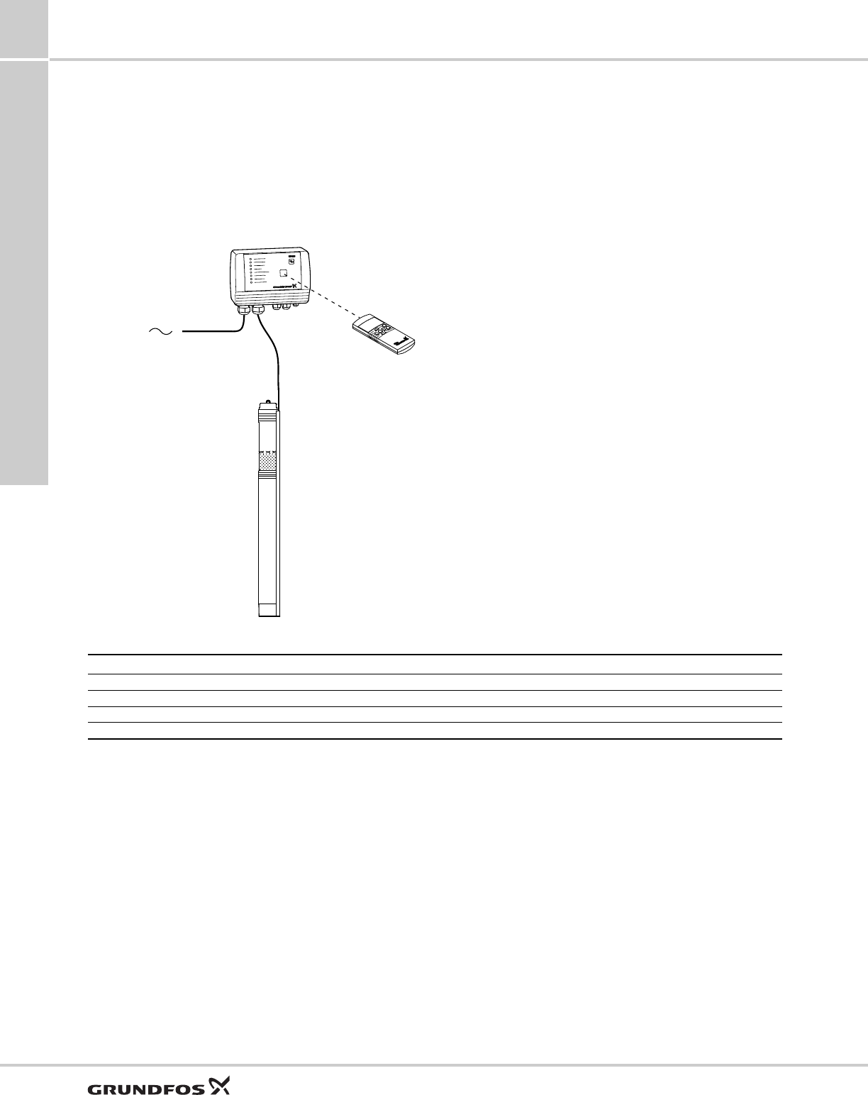
Setting of operating parameters
Using the R100 and the CU 300 enables change of the
motor speed and thereby setting of the pump to a
specific performance.
The software program "SQE Speed Calculation" has
been developed for the calculation of the speed in
order to obtain the required flow rate and head.
Dry-running protection
The value Pcut-out, ensuring dry-running protection, is
factory-set for the SQE pump.
If the speed of the SQE pump is reduced by more than
1000 rpm, the Pcut-out value must be readjusted by
means of the CU 300 and R100.
Fig. 11 Application example: Workshop setting of operating parameters
TM01 8650 4801
Part Type No. of units Product number Unit price Total price
Pump SQE
Remote control R100
Control unit CU 300
SQE Speed Calculation program
Note: The SQE pump must not be started until the
pump has been completely submerged below the water
table. However, the change of the motor speed can be
made even if the pump is not submerged.
R100
CU 300
SQE
Applications
SQ, SQE, SQE-NE,
CU331SP 2
13
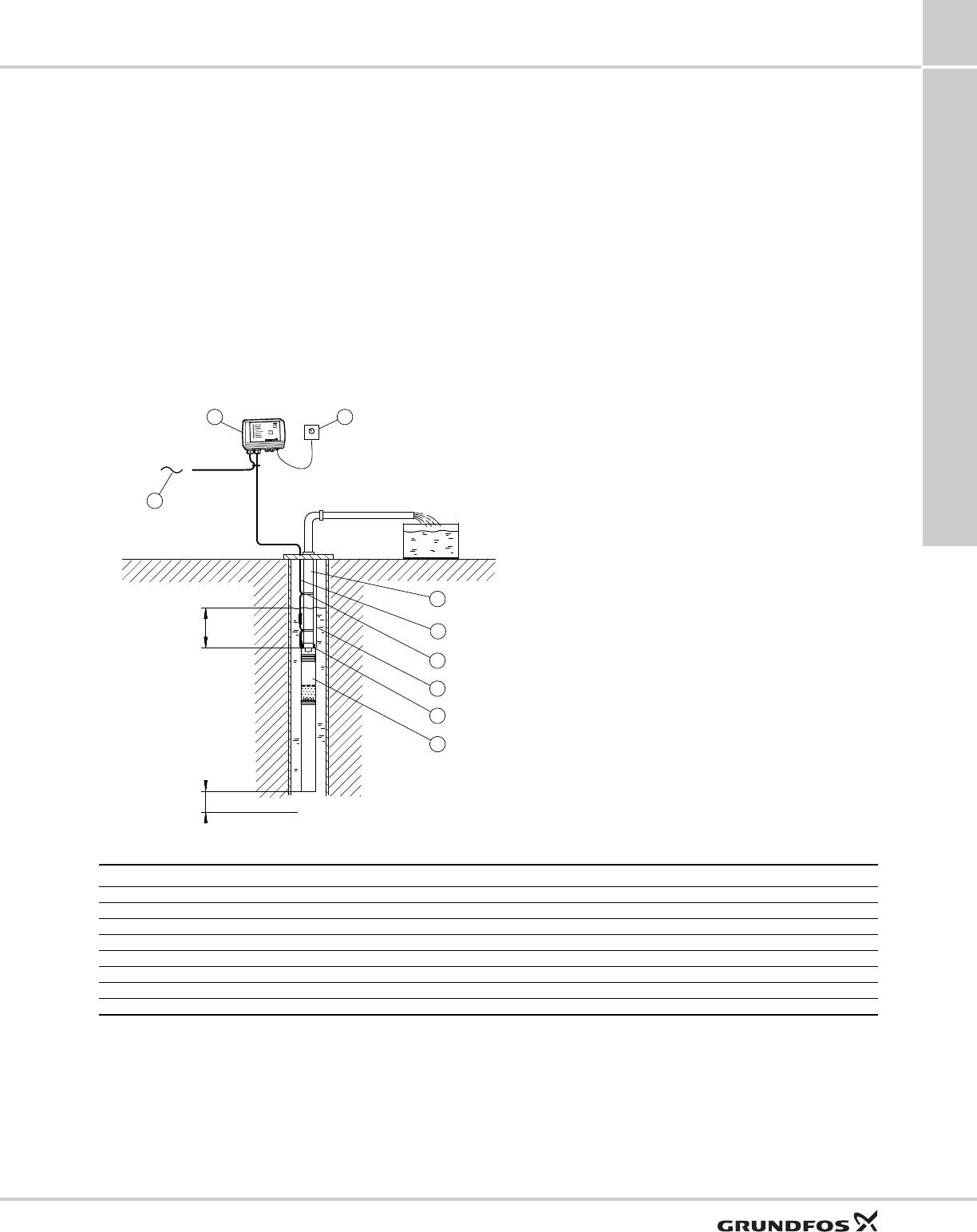
SQE with manual speed control
Functioning and benefits
Manual speed control of the SQE pumps is possible by
means of R100 and an SPP 1 potentiometer.
This application is especially suitable for sampling
from groundwater monitoring wells. The monitoring
well is purged at high speed and the sample is taken at
a low speed (quiet flow). For contaminated
groundwater the SQE-NE type range is recommended.
In case frequent sampling is required, dedicated
installation of the pump is recommended, thus
eliminating wear caused by frequent assembly and
dismantling the installation.
Furthermore, dedicated installations saves the costs of
assembling and dismantling the installation.
Important: Through dedicated installation the transfer
of contamination from one monitoring well to another is
avoided.
Dry-running protection
The value Pcut out, ensuring dry-running protection, is
factory-set for the SQE pump. If the speed of the pump
is reduced more than 1,000 rpm, the value of Pcut out
must be readjusted by means of CU 300 and R100.
Fig. 12 Application example: Sampling/manual speed control of SQE
TM01 9028 4801
21
325
22
2
3
31
1
30
1 SQE pump
2 Cable
3 Cable clips
5 Control unit, CU 300
21 Mains connection
22 Riser pipe
30 Stainless-steel safety cable
31 Stainless-steel wire clamps, 2 per lifting eye
32 Potentiometer, SPP 1
Recommended
min. 20 inches
(0.5 m)
Min. 20 inches
(0.5 m)
Pos. Part Type No. of units Product number Unit price Total price
1Pump SQE
2Cable
3Cable clips
5 Control unit CU 300
22 Riser pipe
30 Stainless-steel safety cable
31 Wire clamps 2 per lifting eye
32 Potentiometer SPP 1
Performance range
SQ, SQE, SQE-NE,
CU331SP
3
14
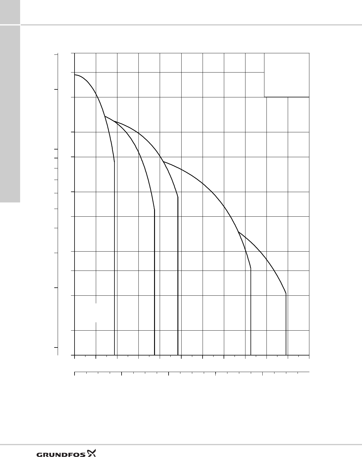
3. Performance range
TM02 9975 2010
0 4 8 12 16 20 24 28 32 36 Q [US GPM]
30
40
60
80
100
150
200
300
400
600
800
[ft]
H
0 2 4 6 8 Q [m³/h]
1010
20
30
40
50
60
70
80
90
100100
200
[m]
H
SQ
ISO 9906 Annex A
SQE
SQE-NE
5 SQ, SQE
10 SQ, SQE, SQE-NE
15 SQ, SQE
22 SQ, SQE, SQE-NE
30 SQ, SQE
Installation
SQ, SQE, SQE-NE,
CU331SP 4
15
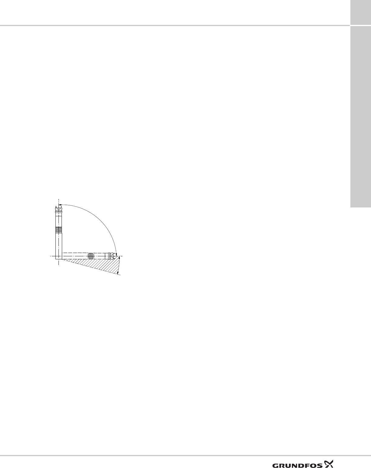
4. Installation
The SQ and SQE, SQE-NE may be installed vertically,
horizontally or in any position in between.
Note: The pump must not fall below the horizontal
level in relation to the motor.
The following features ensure simple installation of the
pump:
• Built-in check valve with spring
• low weight ensuring user-friendly handling
• installation in 3" or larger boreholes
• only on/off switch is needed, which means that no
extra motor starter / starter box is necessary.
For horizontal installation a flow sleeve is
recommended in order to:
• ensure sufficient flow velocity past the motor and
thus provide sufficient cooling
• prevent motor and electronic unit from being buried
in sand or mud.
Fig. 13 SQE installation
TM01 1375 1498
Allowed
Not allowed
Sizing and selection
SQ, SQE, SQE-NE,
CU331SP
5
16
5. Sizing and selection
System sizing guide
Step 1
Calculate minimum head requirements at no flow conditions:
Hmax (required) = dynamic head + system pressure (in feet) + above grade elevation + friction loss
Step 2
Select pump from chart as follows:
• Choose model family based on the desired flow rate (i.e. 15SQE for a flow rate of 15 gpm)
• Select the first model with a value in Column 2 greater than the Hmax calculated in Step 1
(For example: the choice for a 22 gpm model with an Hmax of 140 ft would be the 22SQE-160).
• Double check your selection in the performance curves; see 7. SQ curve charts on p. 18.
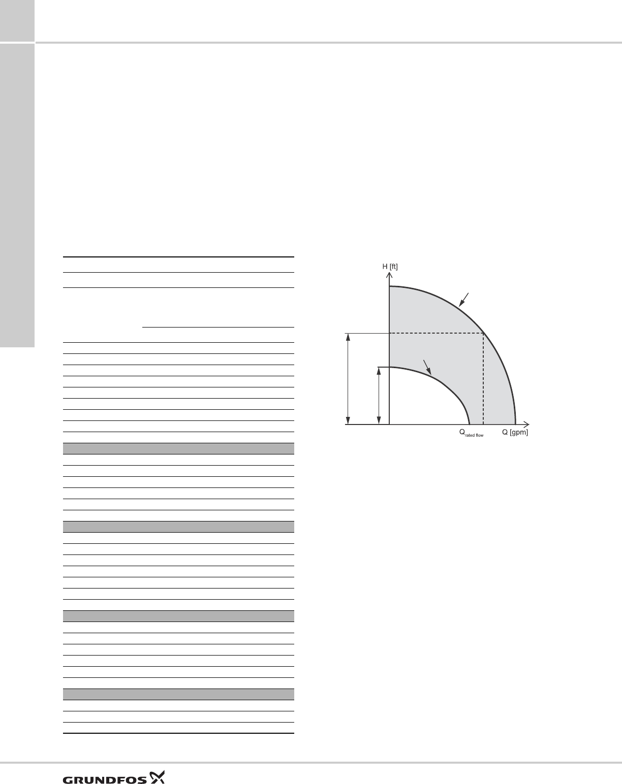
Fig. 14 Recommended sizing
Note: All calculated head requirements must lie
between the selected pump models minimum and
maximum speed curves.
System sizing matrix
Column 1 Column 2
Pump type
Model B
Shutoff head (0
gpm)
@ 3000 rpm
min. speed
Head @ rated gpm
@ 10700 rpm
max. speed
TDH [feet] TDH [feet]
5SQE-90 11 86
5SQE-140 17 131
5SQE-180 22 177
5SQE-230 28 222
5SQE-270 34 270
5SQE-320 39 315
5SQE-360 45 360
5SQE-410 51 405
5SQE-450 56 450
10SQE-110 12 105
10SQE-160 17 164
10SQE-200 23 215
10SQE-240 29 267
10SQE-290 34 328
10SQE-330 40 390
15SQE-70 10 75
15SQE-110 14 123
15SQE-150 19 164
15SQE-180 24 205
15SQE-220 29 246
15SQE-250 33 287
15SQE-290 38 328
22SQE-40 5 36
22SQE-80 9 77
22SQE-120 14 117
22SQE-160 18 159
22SQE-190 23 200
22SQE-220 27 240
30SQE-40 5 33
30SQE-90 11 82
30SQE-130 16 126
TM01 8547 0400
Pump curve
at 10,700 ft
Pump curve
at 3,000 rpm
Max. head at rated flow
Max. head at no flow
Cable sizing
SQ, SQE, SQE-NE,
CU331SP 6
17
6. Cable sizing
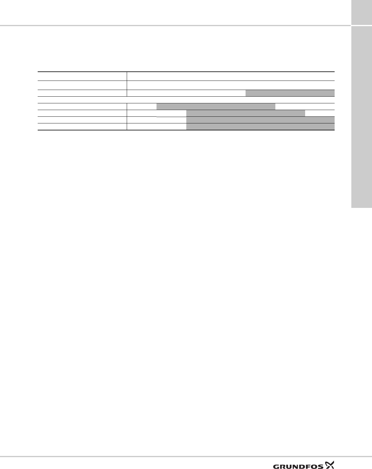
Cable sizing chart
Cable length in feet.
Note: shaded values do not apply when using a CU 301 as its max. recommended cable length is 650 ft.
Motor rating Copper wire size (AWG)
VoltsHpAmps1412108642
115 0.5 12 140 220 360 550 880 1390 2260
230 0.5 5.2 640 1000 1660 2250 4060 — —
230 0.75 8.4 400 620 1030 1580 2510 3970 —
230 1 11.2 300 460 770 1190 1890 2980 4850
230 1.5 12 280 430 720 1110 1760 2780 4530
SQ curve charts
SQ, SQE, SQE-NE,
CU331SP
7
18
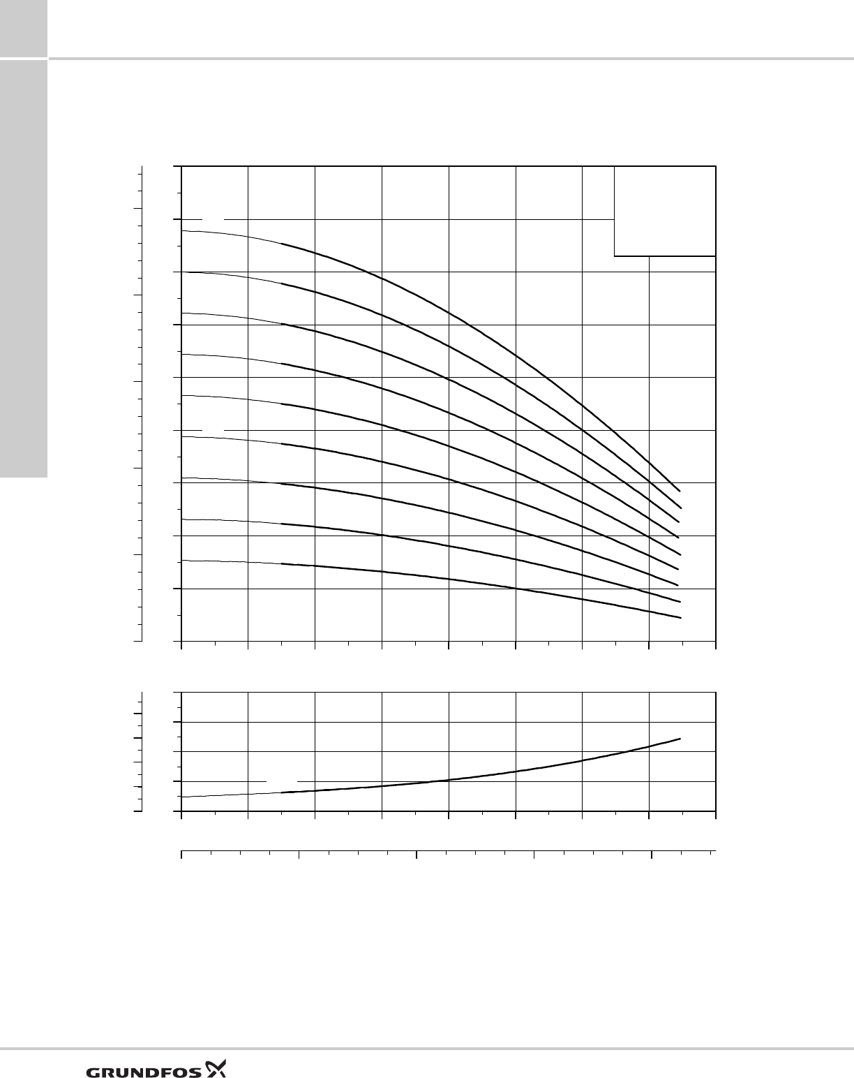
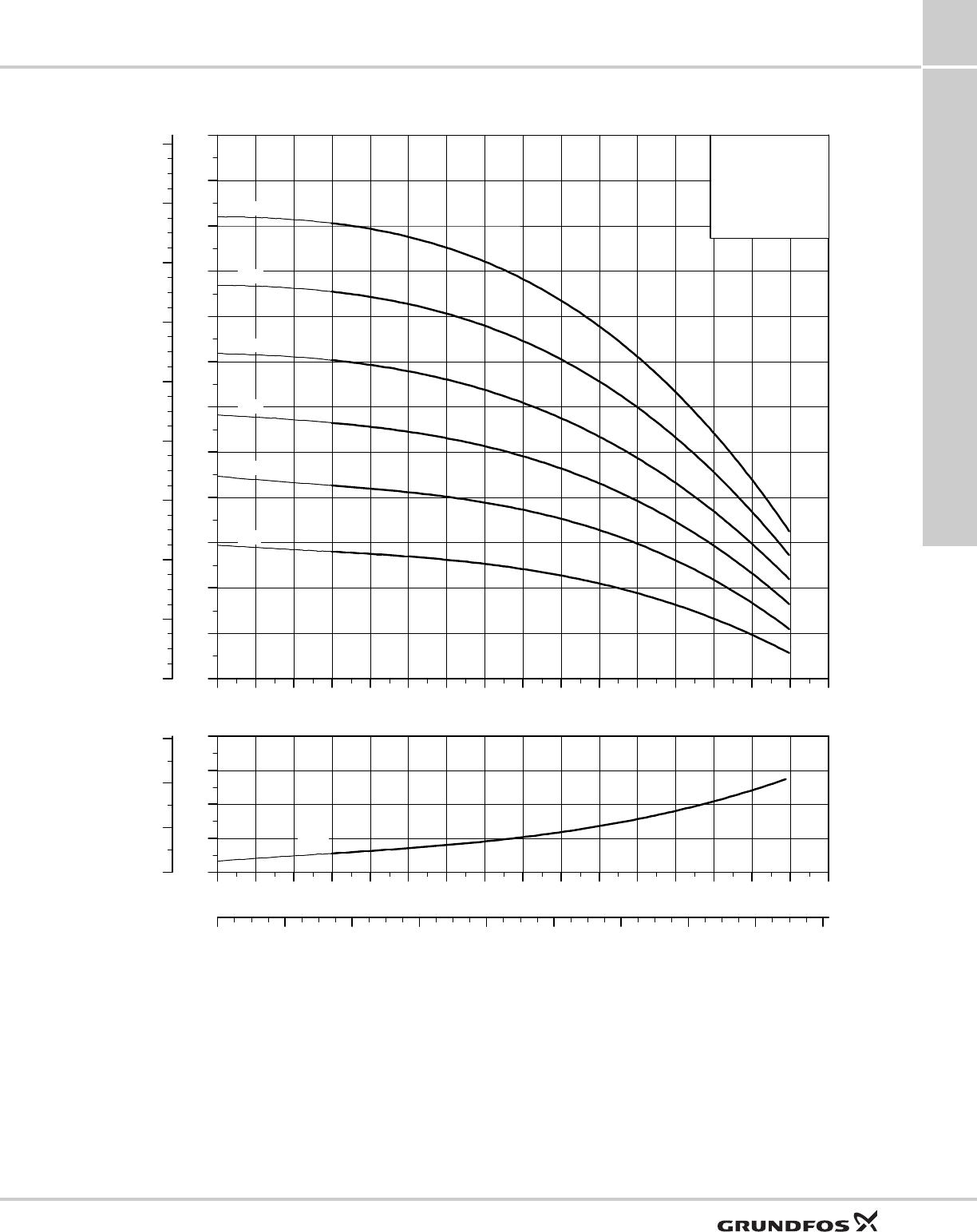
7. SQ curve charts
5 SQ, SQE
TM04 7463 2010
0 1 2 3 4 5 6 Q [US GPM]
0
100
200
300
400
500
600
700
800
[ft]
H
0
50
100
150
200
250
[m]
H
5 SQ
ISO 9906 Annex A
5 SQE
-450
-410
-360
-320
-270
-230
-180
-140
-90
0 1 2 3 4 5 6 Q [US GPM]
0
8
16
24
[ft]
H
0
2
4
6
[m]
H
0.0 0.4 0.8 1.2 1.6 Q [m³/h]
NPSH
SQ curve charts
SQ, SQE, SQE-NE,
CU331SP 7
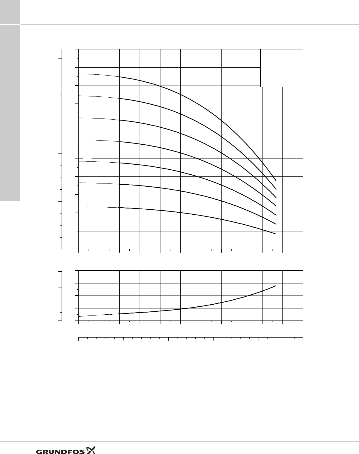
19
10 SQ, SQE
TM04 7464 2010
0 1 2 3 4 5 6 7 8 9 10 11 12 13 Q [US GPM]
0
50
100
150
200
250
300
350
400
450
500
550
[ft]
H
0
20
40
60
80
100
120
140
160
[m]
H
10 SQ
ISO 9906 Annex A
10 SQE
-330
-290
-240
-200
-160
-110
0 1 2 3 4 5 6 7 8 9 10 11 12 13 Q [US GPM]
0
10
20
30
[ft]
H
0
4
8
[m]
H
0.0 0.4 0.8 1.2 1.6 2.0 2.4 2.8 3.2 Q [m³/h]
NPSH
SQ curve charts
SQ, SQE, SQE-NE,
CU331SP
7
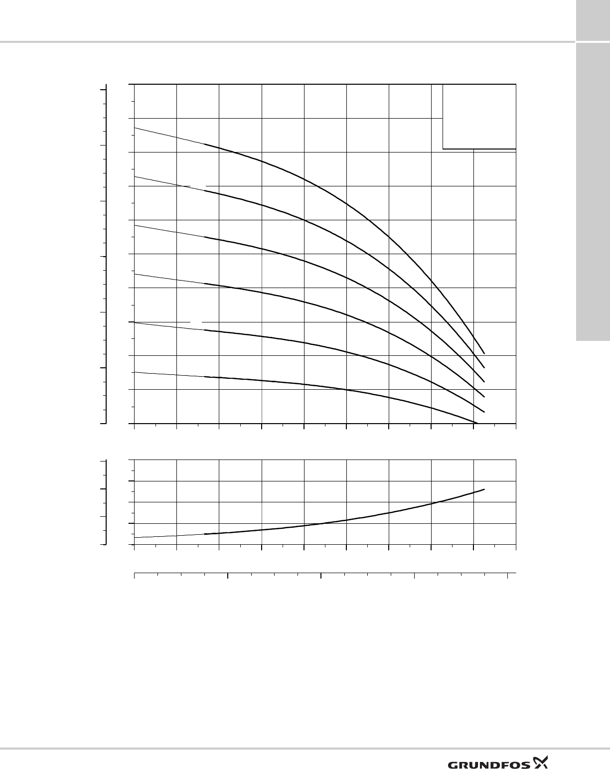
20
15 SQ, SQE
TM04 7465 2010
0 2 4 6 8 10 12 14 16 18 Q [US GPM]
0
50
100
150
200
250
300
350
400
450
500
[ft]
H
0
40
80
120
[m]
H
15 SQ
ISO 9906 Annex A
15 SQE
-290
-250
-220
-180
-150
-110
-70
0 2 4 6 8 10 12 14 16 18 Q [US GPM]
0
10
20
30
[ft]
H
0
4
8
[m]
H
0 1 2 3 4 Q [m³/h]
NPSH
SQ curve charts
SQ, SQE, SQE-NE,
CU331SP 7
21
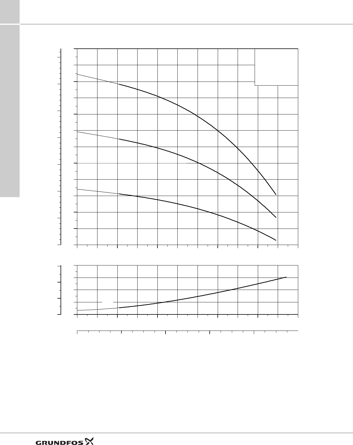
22 SQ, SQE
TM04 7466 2010
0 4 8 12 16 20 24 28 Q [US GPM]
0
40
80
120
160
200
240
280
320
360
[ft]
H
0
20
40
60
80
100
[m]
H
22 SQ
ISO 9906 Annex A
22 SQE
-220
-190
-160
-120
-80
-40
0 4 8 12 16 20 24 28 Q [US GPM]
0
10
20
30
[ft]
H
0 2 4 6 Q [m³/h]
0
4
8
[m]
H
NPSH
SQ curve charts
SQ, SQE, SQE-NE,
CU331SP
7
22
30 SQ, SQE
TM04 7467 2010
0 4 8 12 16 20 24 28 32 36 Q [US GPM]
0
20
40
60
80
100
120
140
160
180
200
220
[ft]
H
0
10
20
30
40
50
60
[m]
H
30 SQ
ISO 9906 Annex A
30 SQE
-130
-90
-40
0 4 8 12 16 20 24 28 32 36 Q [US GPM]
0
10
20
30
[ft]
H
0
4
8
[m]
H
0 2 4 6 8 Q [m³/h]
NPSH
SQ curve charts
SQ, SQE, SQE-NE,
CU331SP 7
23
10 SQE-NE
TM04 7468 2010
0 2 4 6 810 12 Q [US GPM]
0
50
100
150
200
250
300
350
400
450
500
550
[ft]
H
0
20
40
60
80
100
120
140
160
[m]
H
ISO 9906 Annex A
10 SQE - NE
-340
-300
-260
-220
-180
-140
-100
0 2 4 6 810 12 Q [US GPM]
0
10
20
30
[ft]
H
0
4
8
[m]
H
0 1 2 3Q [m³/h]
NPSH
SQ curve charts
SQ, SQE, SQE-NE,
CU331SP
7
24
22 SQE-NE
TM04 7469 2010
0 4 812 16 20 24 28Q [US GPM]
0
40
80
120
160
200
240
280
320
[ft]
H
0
20
40
60
80
100
[m]
H
ISO 9906 Annex A
22 SQE - NE
-210
-180
-140
-110
-80
-40
0 4 812 16 20 24 28Q [US GPM]
0
8
16
24
[ft]
H
0
2
4
6
[m]
H
0 2 4 6 Q [m³/h]
NPSH

Technical data
SQ, SQE, SQE-NE,
CU331SP 8
25
8. Technical data
Electrical data
Control units CU 300 and CU 301
Operating conditions
Storage conditions
Supply voltage: 1x200-240V +6%/-10%, 50/60 Hz, PE
1x100-115V +6%/-10%, 50/60 Hz, PE
Operation via generator: As a minimum, the generator output must be equal to the motor P1[kw] + 10%
Starting current: The motor starting current is equal to the highest value stated on the motor nameplate
Starting: Soft Start
Run-up time: Maximum: 2 seconds
Motor protection:
Motor is protected against:
– Dry running
– overvoltage
– undervoltage
– overload
– overtemperature.
Power factor: PF=1
Motor cable: 3 wire, 14AWG XLPE, 5 ft
Motor liquid: Type SML 2
pH Values: SQ and SQE: 5 to 9
SQE-NE: 2 to 13
Liquid temperature: The temperature of the pumped liquid must not exceed 86 °F (30 °C)
Note: If liquids with a viscosity higher than that of water are to be pumped, please contact Grundfos.
Voltage: 1 x 100-240 V – 10 %/+ 6 %, 50/60 Hz, PE
Power consumption: 5 W
Current consumption: Maximum 130 mA
Enclosure class: IP 55
Ambient temperature: During operation: –22 °F to +122 °F (–30 °C to +50 °C)
During storage: –22 °F to 140 °F ( –30 °C to +60 °C)
Relative air humidity: 95 %.
Pump cable: Maximum length between CU 300 or CU 301 and pump: 650 ft (198 m)
Back-up fuse: Maximum: 16 A
Radio noise: CU 300 and CU 301 comply with EMC Directive 89/336/EEC.
Approved according to the standards EN 55014 and EN 55014-2
Marking: CE, cUL (CU 301)
Load: Max. 100 mA
Minimum ambient fluid temperature: +34 °F (+1 °C)
Maximum ambient fluid temperature: +86 °F (+30 °C)
Well diameter: 3-inch or larger
Installation depth (maximum): 500 feet below static water level
Minimum ambient temperature: –4 °F (–20 °C)
Maximum ambient temperature: +140 °F (+60 °F)
Frost protection: If the pump has to be stored after use, it must be stored at a frost-free location, or it must be ensured that
the motor liquid is frost-proof.

Technical data
SQ, SQE, SQE-NE,
CU331SP
8
26
Motor data
Pump type Hp Voltage Full load amps Overload amps Min.
well
diameter Discharge
230V 115V 230V 115V
5SQE05-90 1/2 230V / 115V 2.1 4.2 5 11 3" 1" NPT
5SQE05-140 1/2 230V / 115V 2.9 6.0 5 11 3" 1" NPT
5SQE05-180 1/2 230V / 115V 3.7 7.7 5 11 3" 1" NPT
5SQE07-230 3/4 230V 4.6 - 8 - 3" 1" NPT
5SQE07-270 3/4 230V 5.3 - 8 - 3" 1" NPT
5SQE07-320 3/4 230V 6.2 - 8 - 3" 1" NPT
5SQE10-360 1 230V 7.2 - 11 - 3" 1" NPT
5SQE10-410 1 230V 8.1 - 11 - 3" 1" NPT
5SQE15-450 1 1/2 230V 9.2 - 12 - 3" 1" NPT
10SQE05-110 1/2 230V / 115V 2.9 6.1 5 11 3" 1 1/4" NPT
10SQE05-160 1/2 230V / 115V 4.1 8.6 8 11 3" 1 1/4" NPT
10SQE07-200 3/4 230V 5.3 - 8 - 3" 1 1/4" NPT
10SQE7-240 3/4 230V 6.0 - 8 - 3" 1 1/4" NPT
10SQE10-290 1 230V 7.7 - 11 - 3" 1 1/4" NPT
10SQE15-330 1 1/2 230V 8.9 - 12 3" 1 1/4" NPT
15SQE05-70 1/2 230V / 115V 2.9 6.0 5 11 3" 1 1/4" NPT
15SQE05-110 1/2 230V / 115V 4.0 8.3 5 11 3" 1 1/4" NPT
15SQE07-150 3/4 230V 5.1 - 8 - 3" 1 1/4" NPT
15SQE07-180 3/4 230V 6.2 - 8 - 3" 1 1/4" NPT
15SQE10-220 1 230V 7.4 - 11 - 3" 1 1/4" NPT
15SQE10-250 1 230V 8.4 - 11 - 3" 1 1/4" NPT
15SQE15-290 1 1/2 230V 9.7 - 12 - 3" 1 1/4" NPT
22SQE05-40 1/2 230V / 115V 1.9 3.9 5 - 3" 1 1/2" NPT
22SQE05-80 1/2 230V / 115V 3.4 7.2 5 - 3" 1 1/2" NPT
22SQE07-120 3/4 230V 4.9 - 8 - 3" 1 1/2" NPT
22SQE10-160 1 230V 6.4 - 8 - 3" 1 1/2" NPT
22SQE10-190 1 230V 7.9 - 11 - 3" 1 1/2" NPT
22SQE15-220 1 1/2 230V 9.5 - 12 - 3" 1 1/2" NPT
30SQE05-40 1/2 230V / 115V 2.8 5.7 5 - 3" 1 1/2" NPT
30SQE07-90 3/4 230V 5.2 - 8 - 3" 1 1/2" NPT
30SQE10-130 1 230V 7.6 - 11 - 3" 1 1/2" NPT

Technical data
SQ, SQE, SQE-NE,
CU331SP 8
27
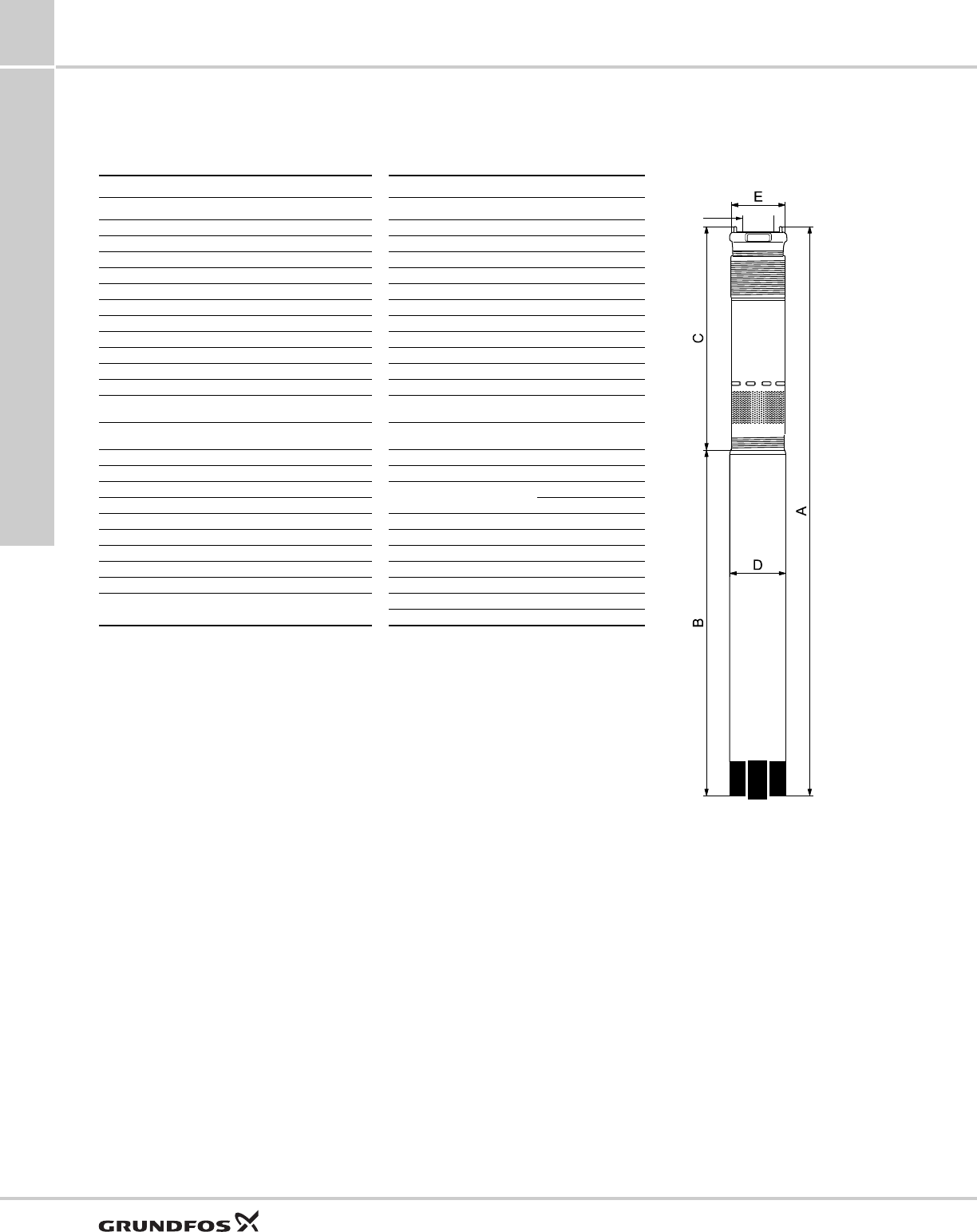
Dimensions and weights
SQ, SQE
SQE-NE
Model Hp Motor
size Discharge
size
Dimensions in inches Approx.
ship. wt.
ABCDE
5SQ/SQE05-90 1/2 3" 1" NPT 30.4 19.8 10.6 2.6 2.9 12
5SQ/SQE05-140 1/2 3" 1" NPT 30.4 19.8 10.6 2.6 2.9 12
5SQ/SQE05-180 1/2 3" 1" NPT 31.5 19.8 11.6 2.6 2.9 12
5SQ/SQE07-230 3/4 3" 1" NPT 33.6 19.8 13.7 2.6 2.9 13
5SQ/SQE07-270 3/4 3" 1" NPT 33.6 19.8 13.7 2.6 2.9 13
5SQ/SQE07-320 3/4 3" 1" NPT 34.6 19.8 14.8 2.6 2.9 13
5SQ/SQE10-360 1 3" 1" NPT 38.2 21.3 16.9 2.6 2.9 16
5SQ/SQE10-410 1 3" 1" NPT 38.2 21.3 16.9 2.6 2.9 16
5SQ/SQE15-450 1 1/2 3" 1" NPT 39.3 21.3 18.0 2.6 2.9 16
10SQ/SQE05-110 1/2 3" 1 1/4" NPT 30.4 19.8 10.6 2.6 2.9 12
10SQ/SQE05-160 1/2 3" 1 1/4" NPT 30.4 19.8 10.6 2.6 2.9 12
10SQ/SQE07-200 3/4 3" 1 1/4" NPT 31.5 19.8 11.6 2.6 2.9 13
10SQ/SQE07-260 3/4 3" 1 1/4" NPT 33.6 19.8 13.7 2.6 2.9 13
10SQ/SQE10-290 1 3" 1 1/4" NPT 35.0 21.3 13.7 2.6 2.9 16
10SQ/SQE15-330 1 1/2 3" 1 1/4" NPT 36.14 21.3 14.8 2.6 2.9 16
15SQ/SQE05-70 1/2 3" 1 1/4" NPT 30.4 19.8 10.6 2.6 2.9 12
15SQ/SQE05-110 1/2 3" 1 1/4" NPT 30.4 19.8 10.6 2.6 2.9 12
15SQ/SQE07-150 3/4 3" 1 1/4" NPT 31.5 19.8 11.6 2.6 2.9 13
15SQ/SQE07-180 3/4 3" 1 1/4" NPT 33.6 19.8 13.7 2.6 2.9 13
15SQ/SQE10-220 1 3" 1 1/4" NPT 35.0 21.3 13.7 2.6 2.9 16
15SQ/SQE10-250 1 3" 1 1/4" NPT 36.1 21.3 14.8 2.6 2.9 16
15SQ/SQE10-290 1 1/2 3" 1 1/4" NPT 38.2 21.3 16.9 2.6 2.9 16
22SQ/SQE05-40 1/2 3" 1 1/2" NPT 30.4 19.8 10.6 2.6 2.9 12
22SQ/SQE05-80 1/2 3" 1 1/2" NPT 30.4 19.8 10.6 2.6 2.9 12
22SQ/SQE07-120 3/4 3" 1 1/2" NPT 31.5 19.8 11.6 2.6 2.9 13
22SQ/SQE10-160 1 3" 1 1/2" NPT 33.6 19.8 13.7 2.6 2.9 13
22SQ/SQE10-190 1 3" 1 1/2" NPT 38.2 21.3 16.9 2.6 2.9 16
22SQ/SQE15-220 1 1/2 3" 1 1/2" NPT 38.2 21.3 16.9 2.6 2.9 16
30SQ/SQE05-40 1/2 3" 1 1/2" NPT 30.4 19.8 10.6 2.6 2.9 12
30SQ/SQE07-90 3/4 3" 1 1/2" NPT 30.4 19.8 10.6 2.6 2.9 13
30SQ/SQE10-130 1 3" 1 1/2" NPT 35.0 21.3 13.7 2.6 2.9 13
10SQE-05-100NE 1/2 3" 1 1/4" NPT 30.4 19.8 10.6 2.6 2.9 12
10SQE-05-140NE 1/2 3" 1 1/4" NPT 30.4 19.8 10.6 2.6 2.9 12
10SQE-05-180NE 3/4 3" 1 1/4" NPT 31.5 19.8 11.6 2.6 2.9 13
10SQE-07-220NE 3/4 3" 1 1/4" NPT 33.6 19.8 13.7 2.6 2.9 13
10SQE-10-260NE 1 3" 1 1/4" NPT 35.0 21.3 13.7 2.6 2.9 16
10SQE-10-300NE 1 3" 1 1/4" NPT 36.1 21.3 14.8 2.6 2.9 16
10SQE-10-340NE 1 3" 1 1/4" NPT 38.2 21.3 16.9 2.6 2.9 16
22SQE05-40NE 1/2 3" 1 1/2" NPT 30.4 19.8 10.6 2.6 2.9 12
22SQE05-80NE 1/2 3" 1 1/2" NPT 30.4 19.8 10.6 2.6 2.9 12
22SQE07-110NE 3/4 3" 1 1/2" NPT 31.5 19.8 11.6 2.6 2.9 13
22SQE07-140NE 3/4 3" 1 1/2" NPT 33.6 19.8 13.7 2.6 2.9 13
22SQE10-180NE 1 3" 1 1/2" NPT 38.2 21.3 16.9 2.6 2.9 16
22SQE10-210NE 1 3" 1 1/2" NPT 38.2 21.3 16.9 2.6 2.9 16
Construction
SQ, SQE, SQE-NE,
CU331SP
9
28
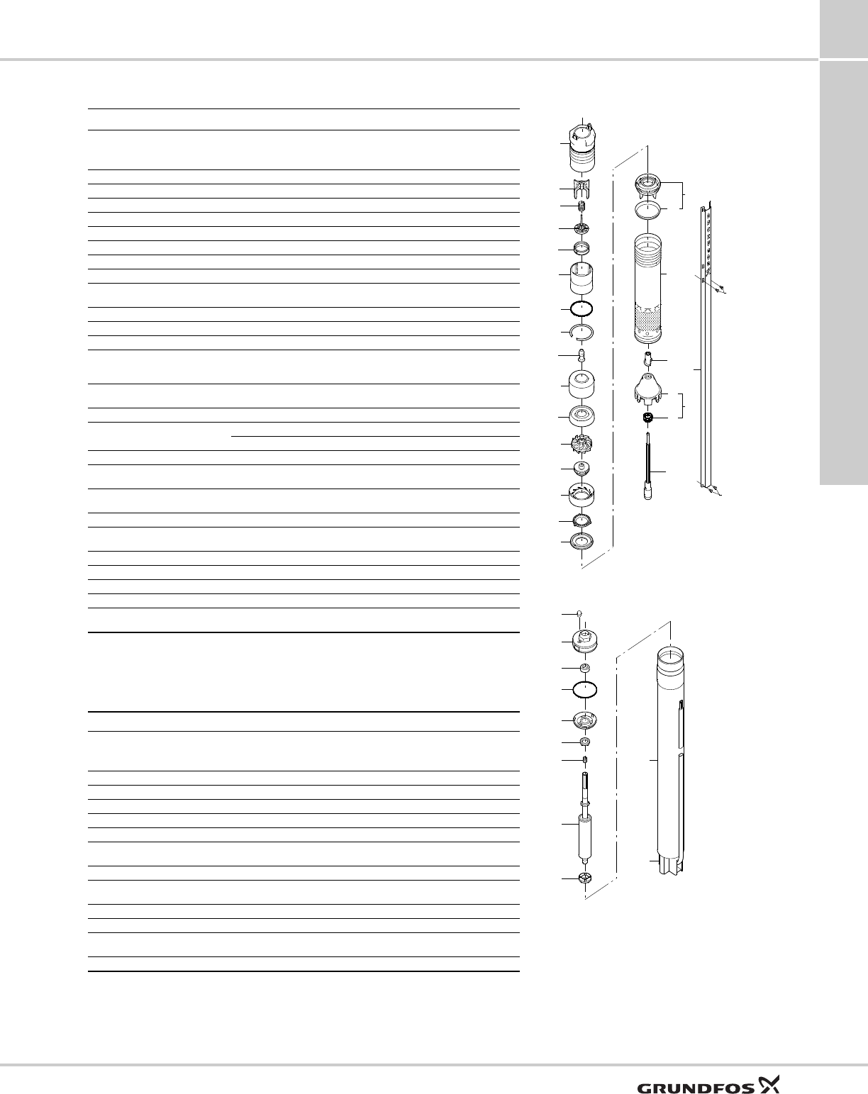
9. Construction
Materials of construction
SQ, SQE SQE-NE
TM04 7522 2110
Component Splined shaft Component Splined shaft
Valve casing Polyamide Valve casing PVDF
Discharge chamber 304 stainless steel Discharge chamber 316 stainless steel
Valve guide Polyamide O-ring FPM rubber
Valve spring 316LN stainless steel Valve cone PVDF
Valve cone Polyamide Valve seat FPM rubber
Valve seat NBR rubber Top chamber PVDF
O-ring NBR rubber Empty chamber PVDF
Lock ring 310 stainless steel Top bearing FPM rubber
Top bearing NBR rubber Neck ring PVDF
Top chamber Polyamide Lock ring 316 stainless steel
Guide vanes Polyamide Guide vanes PVDF
Impeller Polyamide w/ tungsten
carbide bearings Bottom chamber PVDF
Bottom chamber Polyamide Impeller w/ tungsten
carbide bearing PVDF
Neck ring TPU / PBT Suction interconnector PVDF
Bearing Aluminum oxide Ring 316 stainless steel
Suction interconnector Polyamide Shaft w/coupling Sintered steel
Ring 304 stainless steel 316 stainless steel
Pump sleeve 304 stainless steel Cable guard 316 stainless steel
Pressure equalization cone Polyamide Cable guard screws 316 stainless steel
Spacer Polyamide Pressure equalization cone PVDF
Sand trap 316 stainless steel Valve spring 316 stainless steel
Shaft w/coupling 304 stainless steel Pump sleeve 316 stainless steel
Cable guard 304 stainless steel Valve guide PVDF
Spacer 316 stainless steel
Discharge sizes:
1" NPT
1 1/4" NPT
1 1/2" NPT
5 SQ/SQE
10 - 15 SQ/SQE
22-30 SQ/SQE
Construction
SQ, SQE, SQE-NE,
CU331SP 9
29
Material specification
Pump
Pos. Component Material DIN
W-Nr.
SQ/SQE AISI DIN
W-Nr.
SQ/-NE AISI
1 Valve casing Polyamide 1.4301 304 1.4401 316
1a Discharge chamber Stainless steel
1d O-ring NBR rubber
2 Valve cup Polyamide
3 Valve seat NBR rubber
4a Empty chamber Polyamide
6 Top bearing NBR rubber
7 Neck ring TPU / PBT
7a Lock ring Stainless
spring steel 1.4301 310 1.4401 316
7b Neck ring retainer Polyamide
9b Chamber top Polyamide
9c Chamber bottom Polyamide
13
Impeller with
tungsten carbide
bearing
Polyamide
14 Suction
inter-connector Polyamide
14a Ring Stainless steel 1.4301 304 1.4401 316
16 Shaft with coupling Stainless steel 1.4301 304 1.4401 316
Sintered steel
18 Cable guard Stainless steel 1.4301 304 1.4401 316
18a
18b Screws for cable guard Stainless steel 1.4301 316 1.4401 316
30 Cone for pressure
equalization Polyamide
32 Guide vanes Polyamide
39 Spring Stainless
spring steel 1.4406 316LN 1.4406 316LN
55 Pump sleeve Stainless steel 1.4301 304 1.4401 316
64 Priming screw Polyamide
70 Valve guide Polyamide
86 Lip seal ring NBR rubber
87 Cone for pressure
equalization complete
Polyamide /
NBR rubber
TM01 2745 2010
Motor
Pos. Component Material DIN
W-Nr.
SQ-SQE AISI DIN
W-Nr.
SQE-NE AISI
201 Stator Stainless steel 1.4301 304 1.4401 316
202 Rotor Stainless steel 1.4301 304 1.4401 316
202a Stop ring PP
202b Filter Polyester
203 Thrust bearing Carbon
205 Radial bearing Ceramic
tungsten carbine
220 Motor cable with plug EPR
222a Filling plug MS 3: NBR
MSE 3: FKM
224 O-ring FKM
225 Top cover PPS
232 Shaft seal MS 3: NBR
MSE 3: FKM
Motor liquid SML-2
1d
7a
1
70
2
39
3
1a
55
16
30
86
87
64
18
18b
18a
6
4a
9b
32
13
9c
7
14
14a
7b
202a
202
202b
222a
232
203
224
205
225
201
220
Control units
SQ, SQE, SQE-NE,
CU331SP
10
30
10. Control units
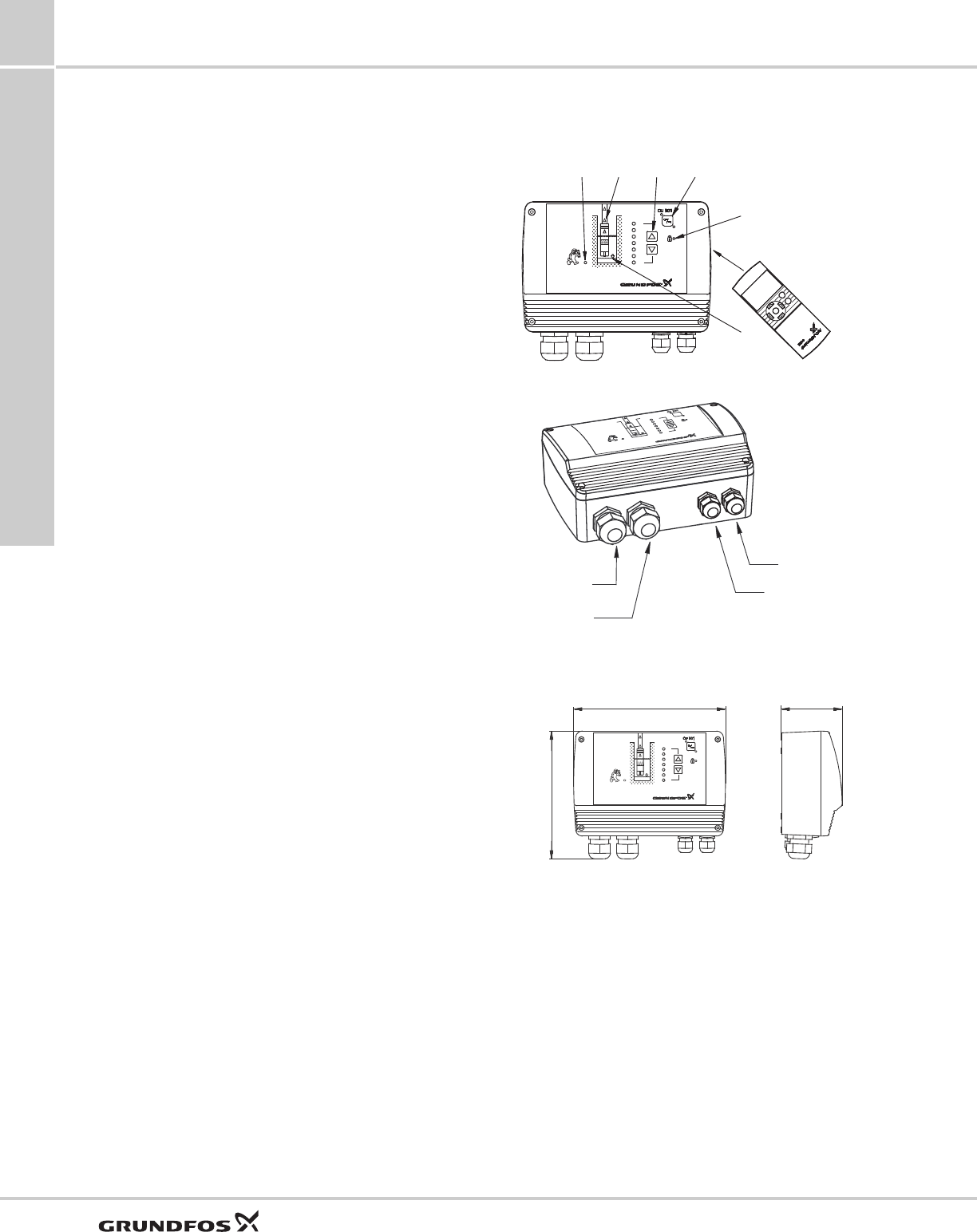
CU 301
The CU 301 is a control and communication unit
developed especially for the SQE submersible pumps
in constant-pressure applications.
The CU 301 control unit provides:
• Full control of the SQE pumps
• two-way communication with the SQE pumps
• possibility of adjusting the pressure
• alarm indication (LED) when service is needed
• possibility of starting, stopping and resetting the
pump simply by means of a push-button
• configuration with R100 remote control.
The CU 301 communicates with the pump via mains
borne signalling (Power Line Communication),
meaning that no extra cables are required between the
CU 301 and the pump.
The CU 301 features the following indications
(see drawing in right column):
1. Pump running indicator
2. System pressure setting
3. System ON/OFF
4. Button lock indicator
5. Dry-running indicator
6. Service needed in case of:
– – no contact to pump
– overvoltage
– undervoltage
– speed reduction
– overtemperature
– overload
– sensor defective.
The CU 301 incorporates:
• External signal input for pressure sensor
• connection to an operating relay for indication of
pump operation.
Optional R100 remote control
Wireless infrared remote control of the CU 301 is
possible by means of the R100.
Using the R100, it is possible to monitor and change
the operating parameters, see the R100 menu
structure on page 31.
The R100 is a valuable tool in case fault finding is
required.
Fig. 15 CU 301 control unit
Fig. 16 CU 301 entry ports
Fig. 17 CU 301 dimensions
TM03 3426 0406TM02 3427 0406TM03 3003 2010
bar
5.0
4.5
4.0
3.5
3.0
2.5
2.0
23
4
1
5
6
R 100
R100
Pressure
sensor entry
Power supply
entry
Submersible drop
cable entry
Operating
relay entry
9.13 in.
(232 mm)
4.49 in.
(114 mm)
7.68 in.
(195 mm)
bar
5.0
4.5
4.0
3.5
3.0
2.5
2.0
Control units
SQ, SQE, SQE-NE,
CU331SP 10
31
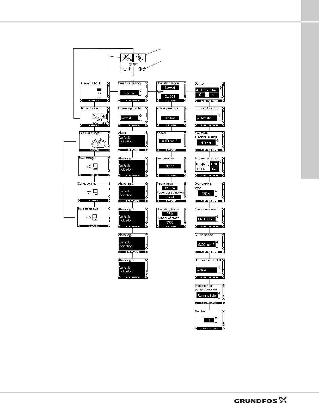
R100 menu structure for CU 301 control unit
1.1
1.2
1.3
2.1
2.2
2.3
2.4
2.5
2.6
3.1
3.2
3.3
3.4
3.5
3.6
3.7
3.8
3.9
1.4
1.5
1.6
1.7
1.8
Note: This menu is an example, not the factory setting.
Start
Contrast
Setting
Light
0. General 1. Operation 2. Status 3. Installation
3.10
USB
version
only

Control units
SQ, SQE, SQE-NE,
CU331SP
10
32
R100 menus for CU 301
0. General
1. Operation
1.1 Setpoint setting
1.2 Selection of operating mode
1.3 Alarm indication.
2. Status
The indication of:
2.1 Actual operating mode
2.2 Actual pressure
2.3 Actual motor speed
2.4 Actual motor temperature
2.5 Actual power input and accumulated motor power
consumption
2.6 Accumulated number of operating hours and
accumulated number of starts.
3.Installation
3.1 Sensor parameters
3.2 Choice of sensor
3.3 Setting of maximum pressure setpoint
3.4 Setting of automatic restart time
3.5 Setting of the dry-running stop limit
3.6 Setting of the maximum motor speed
3.7 Setting of the cut-in motor speed
3.8 Activating or deactivating the on/off-button and
the buttons for system pressure setting on the
CU 301
3.9 Indication of pump operation
3.10 Allocation of identification number.
Control units
SQ, SQE, SQE-NE,
CU331SP 10
33
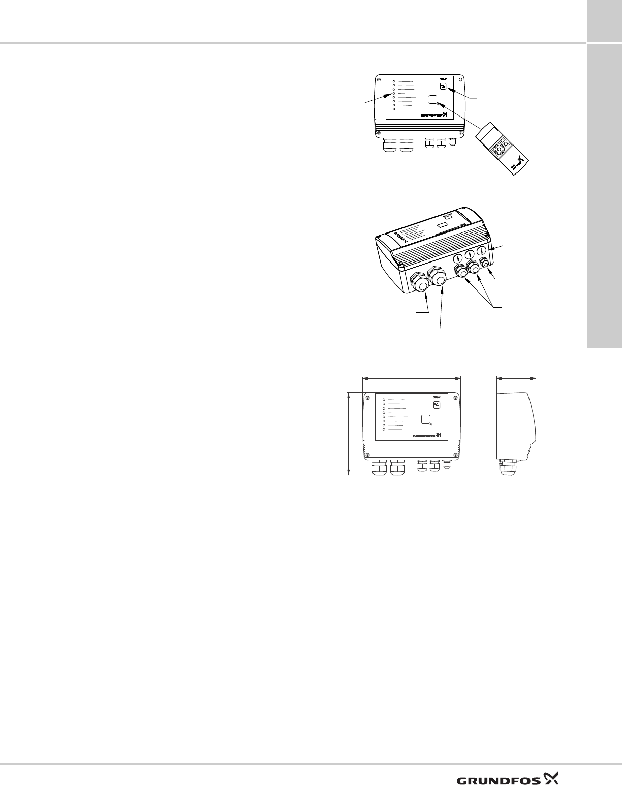
CU 300
The CU 300 is a control and communication unit
developed especially for the SQE submersible pumps
for control applications other than constant pressure.
The CU 300 control unit provides:
• Flexible pump control based on various sensor
inputs
• two-way communication with the SQE pumps
• alarm indication of pump operation by LED’s on the
front
• possibility of starting, stopping and resetting the
pump simply by means of a push-button
• communication with R100 remote control.
The CU 300 communicates with the pump via mains
borne signalling (Power Line Communication),
meaning that no extra cables are required between the
CU 300 and the pump.
The following alarms can be indicated by the CU 300:
• No contact
•overvoltage
• undervoltage
• dry running
• speed reduction
• overtemperature
•overload
• sensor alarm.
The CU 300 incorporates:
• External signal input for two analog sensors and
one digital sensor
• relay output for external alarm indication
• control according to the signals received, e.g. of
flow, pressure, water level and conductivity.
R100 remote control
Wireless infrared remote control of the CU 300 is
possible by means of the R100.
Using the R100, it is possible to monitor and change
the operating parameters, see the R100 menu
structure on page 34.
The R100 is a valuable tool in case fault finding is
required.
Fig. 18 CU 300 control unit with R100
Fig. 19 CU 300 control unit, external entry ports
Fig. 20 CU 300 dimensions
TM01 2760 4801TM01 2761 4801TM01 2781 2010
LED alarm
indication On/Off button with
red and green
indicator lights
IR communication
R100
Power supply entry
Submersible drop
cable entry
Extra cable
entries
Fieldbus
entry
Sensor
entries
9.14 in.
(232 mm) 4.49 in.
(114 mm)
7.68 in.
(195 mm)
Control units
SQ, SQE, SQE-NE,
CU331SP
10
34
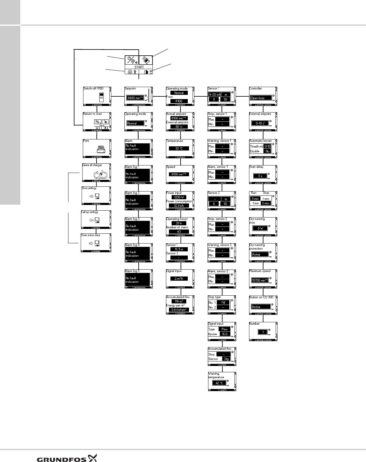
R100 menu structure for the CU 300
1.1
1.2
1.3
2.1
2.2
2.3
2.4
2.5
2.6
2.7
2.8
3.1
3.2
3.3
3.4
3.5
3.6
3.7
3.8
3.9
3.10
3.11
4.1
4.2
4.3
4.4
4.5
4.6
4.7
4.8
3.12
4.9
2.9
4.10
1.4
1.5
1.6
1.7
1.8
Start
Contrast
Setting
Light
0. General 1. Operation 2. Status 4. Installation3. Limits
Note: This menu is an example, not the factory setting.
USB
version
only

Control units
SQ, SQE, SQE-NE,
CU331SP 10
35
R100 menus for CU 300
0. General
1. Operation
1.1 Setpoint setting
1.2 Selection of operating mode
1.3 Alarm indication.
2. Status
The indication of:
2.1 Actual operating mode
2.2 Actual and external setpoint
2.3 Actual motor temperature
2.4 Actual motor speed
2.5 Actual power input and accumulated motor power
consumption
2.6 Accumulated number of operating hours and
accumulated number of starts
2.7 Actual values of sensors 1 and 2, respectively
2.8 Actual values of the digital input
2.9 Accumulated flow, and the power used to pump.
R100 offers the possibility of making a number of
settings.
3. Limits
The setting of:
3.1 Sensor 1 parameters
3.2 Min. and max. stop limits of sensor 1
3.3 Min. and max. warning limits of sensor 1
3.4 Min. and max. alarm limits of sensor 1
3.5 Sensor 2 parameters
3.6 Min. and max. stop limits of sensor 2
3.7 Min. and max. warning limits of sensor 2
3.8 Min. and max. alarm limits of sensor 2
3.9 Filling or emptying
3.10 Setting of the function of the digital sensor
connected to the digital input
3.11 The setting of the water quantity stop limit and
the setting of the sensor to detect water quantity
3.12 The setting of the temperature warning limits of
the motor electronics.
4. Installation
4.1 Selection of controller — open loop, closed loop
4.2 Setting of external setpoint
4.3 Setting of automatic restart time
4.4 Allocation of individual start delays
4.5 Setting of the stop and run times for the
dewatering function
4.6 Setting of the dry-running stop limit
4.7 Activating or deactivating the dry-running
protection
4.8 Setting of the maximum motor speed
4.9 Activating or deactivating the on/off-button on the
CU 300
4.10 Allocation of ID number where more than one
CU 300 is installed.

Control units
SQ, SQE, SQE-NE,
CU331SP
10
36
Examples of R100 displays
Menu OPERATION
Setpoint setting
1.1
From factory, the pump is set to maximum speed,
10,700 rpm. R100 makes it possible to reduce the
pump speed by changing the setpoint. The speed can
be set to 3,000 - 10,700 rpm, at 100 rpm intervals.
The unit of the setpoint is automatically changed
according to the unit of the sensor connected to sensor
input 1.
Example: Sensor input 1 is connected to a pressure
sensor using the unit feet (ft) and the range 0-60.
Consequently, the setpoint of display 1.1 can be set to
between 0-60 ft.
Menu STATUS
The displays appearing in this menu are status
displays only. It is not possible to change settings in
this menu.
Accumulated flow
2.9
In display 2.9, the water quantity (m3)* pumped is
shown. The value shown is the accumulated flow
registered by the sensor selected in display 3.11.
The power used to pump 1 m3 is shown in the display
as energy per m3 (kWh/m3).
It is possible to read the status of the accumulated flow
and energy per m3 at any time.
*Water quantity in units of gpm can be chosen.
Accumulated number of operating hours and
number of starts
2.6
The number of operating hours and the number of
starts are values accumulated from the time of
installation and they cannot be reset.
Both values are stored in the motor electronics, and
they are kept even if the CU 300 is replaced.
The number of operating hours is registered every two
hours of continuous operation.
Menu LIMITS
Sensor 1
3.1
The setting of sensor 1.
Depending on the type of sensor, the following settings
can be made:
• Sensor outputs:
– (not active), 0-10 V, 2-10 V, 0-20 mA, 4-20 mA
• setting range unit: m3/h, m, %, gpm, ft
• sensor minimum value: 0-249 (0, 1, 2, 3.....249)
• sensor maximum value: 1-250 (1, 2, 3, 4.....250).
CU331SP variable frequency drive
SQ, SQE, SQE-NE,
CU331SP 11
37
11. CU331SP variable frequency drive
Features
User interface
The user interface offers these possibilities:
• Local operation via a control panel with graphic
display where the menu structure is based on the
well-known system from Grundfos E-pumps.
• Monitoring of operating status via indicator lights
and signal relays.
• Display of alarm or warning and logging of the last
five alarms and warnings.
Functions
Control mode: Constant pressure
The CU331SP has only one control mode, Constant
pressure. The pressure is kept constant,
independently of the flow rate.
Start-up guide
The CU331SP has a start-up guide, which is launched
at the first power up. Parameters are set manually on
the basis of the installation. The start-up guide can be
repeated, if necessary.
Thanks to the start-up guide, the installer can quickly
set a few parameters and put the CU331SP into
operation.
Direction of rotation test
During start-up, the CU331SP automatically tests and
sets the correct direction of rotation without changing
the cable connections. The direction of rotation test
can be performed manually if it fails for any reason.
Dry-running protection
To protect the pump, the CU331SP will automatically
set up dry-run protection so that water shortage can be
detected. The dry-run alarm will automatically reset 30
minutes after the alarm is declared.
Low-flow stop function
The low-flow stop function is used for changing
between on/off operation at low flow rate and
continuous operation at high flow rate.
The low-flow stop function protects the pump and
saves energy.
Applications
For 4" or larger wells. Main applications:
• Domestic and light commercial water supply
• irrigation
• livestock watering
• water transfer.
System components
• Compact, efficient, and reliable variable frequency
drive
• rugged stainless steel pump end and proven,
reliable, 3-phase motor
• pressure sensor
• diaphragm tank (sold separately).
Fig. 21 CU331SP variable frequency drive and sensor
TM05 5801 4012
CU331SP variable frequency drive
SQ, SQE, SQE-NE,
CU331SP
11
38
Identification
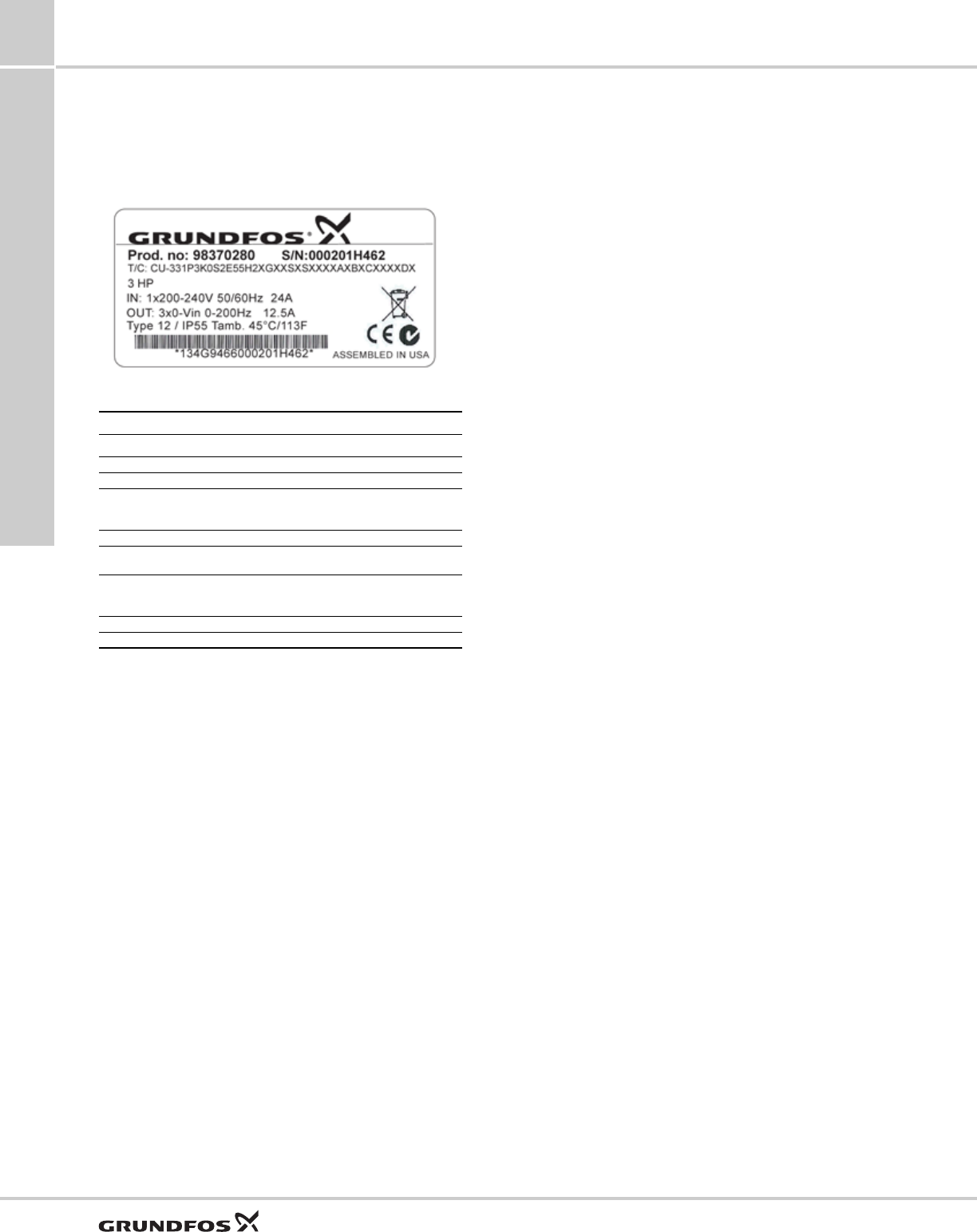
Nameplate
The CU331SP can be identified by means of the
nameplate. An example is shown below.
Fig. 22 Example of nameplate
TM05 6001 4012
Key
Text Description
T/C: CU-331 (product name)
Prod.no: Product number (98370280)
S/N:
Serial number (000201H462)
The last four digits indicate the production date. In
this case, 46 is the week, and 2 is the year 2012.
3.0 hp Typical shaft power on the motor
IN: Supply voltage, frequency and maximum input
current.
OUT:
Motor voltage, frequency and maximum output
current. The maximum output frequency usually
depends on the pump type.
Type 12 / IP55 Enclosure class
Tamb. Maximum ambient temperature
CU331SP variable frequency drive
SQ, SQE, SQE-NE,
CU331SP 11
39
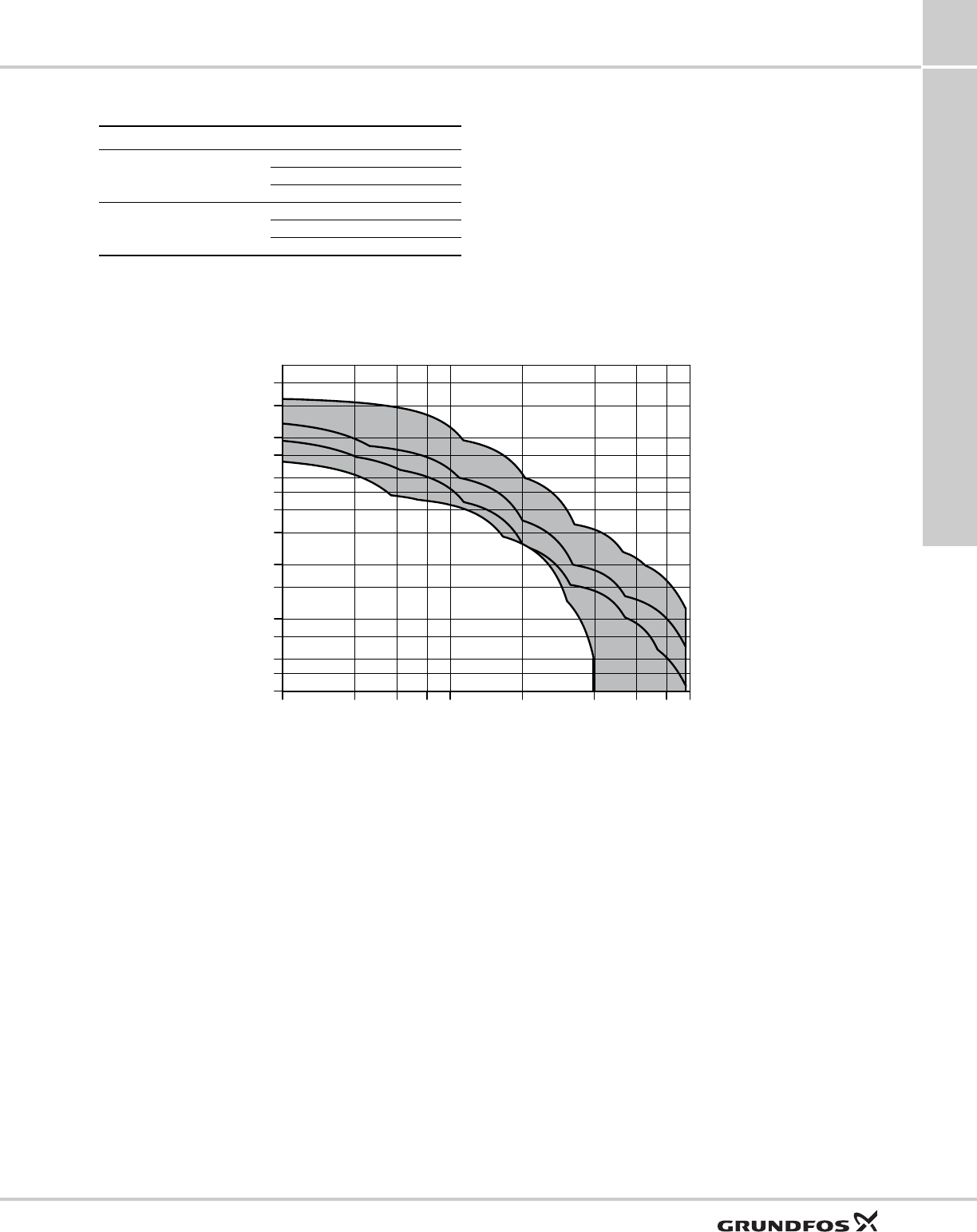
CU331SP product range
CU331SP performance range
CU331SP sizing
Step 1
Calculate maximum head requirements at rated flow
conditions:
Hmax=dynamic head + system psi (in feet) +
friction loss + above grade elevation.
Step 2
Select pump from performance curves as follows:
Select a model in which the calculated value of Hmax is
within the maximum performance curve of the pump.
Refer to section CU331SP curve charts on page 53.
Step 3
Select the CU331SP that corresponds to the correct
motor Hp and enclosure type.
Enclosure type NEMA Hp Input Ph Input volts
Indoor Type 12
2 1 200 - 240
3 1 200 - 240
5 1 200 - 240
Outdoor Type 4X
2 1 200 - 240
3 1 200 - 240
5 1 200 - 240
TM05 6380 5012
2 4 6 8 10 20 40 60 80 100
Q [US GPM]
40
50
60
80
100
150
200
300
400
500
600
800
1000
1500
2000
[ft]
H
SQE
2 Hp
2 Hp
3 Hp
5 Hp

CU331SP variable frequency drive
SQ, SQE, SQE-NE,
CU331SP
11
40
CU331SP operation
Menu structure
The CU331SP has a start-up guide, which is launched
at the first power up. After the start-up guide, the
CU331SP has a menu structure divided into four main
menus:
0. GENERAL gives access to the start-up guide for
the general setting of the CU331SP.
1. OPERATION enables the setting of setpoint and
resetting of alarms. It is also possible to see the
latest five warnings and alarms.
2. STATUS shows the status of the CU331SP and the
pump. It is not possible to change or set values.
3. INSTALLATION gives access to available
parameters.
CU331SP variable frequency drive
SQ, SQE, SQE-NE,
CU331SP 11
41
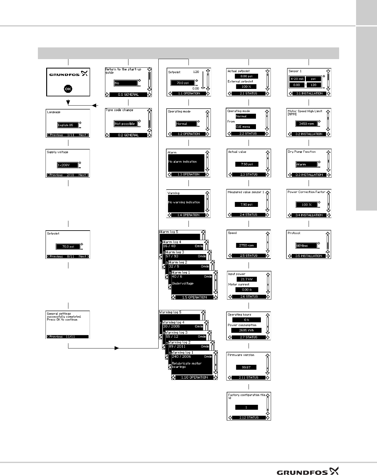
CU331SP menu overview
Fig. 23 Menu overview
START-UP GUIDE 0. GENERAL 1. OPERATION 2. STATUS 3. INSTALLATION
0.1 1.1 2.1 3.1
1/11 0.2 1.2 2.2 3.2
2/11 1.3 2.3 3.3
1.4 2.4 3.4
3/11-7/11
Automatic or manual
setting of the
direction of rotation
8/11 1.5 - 1.9 2.5 3.5
2.6
9/11-10/11
Automatic setting of
Stop and Dry-run
functions
11/11 1.10-1.14 2.7
2.11
2.12
CU331SP variable frequency drive
SQ, SQE, SQE-NE,
CU331SP
11
42
Operating modes
These operating modes can be selected with the
CU331SP:
• Normal
•Stop
•Min.
•Max.
The operating modes can be set without changing the
setpoint setting.
Normal
The pump operates in constant pressure mode.
Stop
The pump has been stopped by user.
Min. curve
The pump is running at a set minimum speed value.
See fig. 24.
For instance, this operating mode can be used during
periods with a very small flow requirement.
Max. curve
The pump is running at a set maximum speed value.
Fig. 24 Min. and max. curves
Control mode
The CU331SP has been developed specifically to
operate submersible pumps in Constant Pressure
mode. This Closed-Loop control mode uses an analog
pressure transducer to provide pressure feedback to
the drive.
Constant pressure with stop function
The outlet pressure is kept constant at high flow rate
(Q > Qmin). On/off operation at low flow rate. See fig.
25.
Fig. 25 Constant pressure with stop function
The pump is controlled according to a constant
pressure measured after the pump.This means that the
pump offers a constant pressure in the Q-range of
Qmin to Qmax, represented by the horizontal line in the
QH diagram.
Setting the setpoint by means of the
OPERATION menu
The setpoint can be set or changed during operation
using the setpoint display in the "OPERATION" menu
shown below. It is not necessary to run the start guide
to change the setpoint.
Low flow and stop functions
The pump will check the flow regularly by reducing the
speed for a short time. If there is no or only a small
change in pressure, this means that there is low flow.
The speed will be increased until the stop pressure
(actual setpoint + 0.5 x ΔH) is reached and the pump
will stop after a few moments. The pump will restart at
the latest when the pressure has fallen to the start
pressure (actual setpoint - 0.5 x ΔH).
TM03 8813 2507
Max.
Min.
TM03 8477 2507
TM03 8807 3307
Hset
Qmin Qmax
CU331SP
CU331SP variable frequency drive
SQ, SQE, SQE-NE,
CU331SP 11
43
Operating conditions for the stop
function
It is only possible to use the stop function if the system
incorporates a pressure sensor, a non-return valve and
a diaphragm tank.
The non-return valve must always be installed before
the pressure sensor.
Fig. 26 Position of the pressure sensor and diaphragm
tank
Diaphragm tank
The stop function requires a diaphragm tank of a
certain minimum size. The tank must be installed as
close as possible after the pump and the precharge
pressure must be 0.7 x actual setpoint.
Recommended diaphragm tank size:
If a diaphragm tank of the above size is installed in the
system, the factory setting of ΔH is the correct setting.
If the tank installed is too small, the pump will start and
stop too often.
Setting the direction of rotation
The start-up guide is started the first time the
CU331SP is connected to supply voltage. Then while
going through the start-up guide, the CU331SP tests
and sets the correct direction of rotation without
changing the cable connections to the motor.
The correct direction of rotation can be set in these
ways:
• automatic setting.
• manual setting when the direction of rotation is not
visible.
Automatic setting
The CU331SP automatically tests and sets the correct
direction of rotation without changing the cable
connections.
Automatic setting requires a sensor.
This test is not suitable for all pump types and will in
certain cases not be able to determine for certainty the
correct direction of rotation. In these cases, the
CU331SP changes over to manual setting where the
direction of rotation is determined on the basis of the
installer’s observations.
Manual setting when the direction of rotation is not
visible
The correct direction of rotation is set manually without
changing the cable connections. This requires that it is
possible to observe the head or flow rate.
Status functions
The CU331SP shows the following data:
• power consumption
• operating hours
• measured value
• speed
• input power
• motor current.
The status information can be shown in the display.
Power consumption
The value of the power consumption is an
accumulated value calculated from the pump’s startup
date and cannot be reset. No additional sensor is
required.
Operating hours
The value of operating hours is an accumulated value
calculated from the pump’s startup date and cannot be
reset. No additional sensor is required.
Measured value
Sensor display will show the actual pressure as
received from the pressure transducer.
Speed
Display will show the motor speed in RPM's
(calculated).
Input power
Display will show the power consumption in kW.
Motor current
Display will show the actual motor current being used.
Logging functions
Alarm and warning log
The latest five alarms and five warnings are logged
with a timestamp corresponding to the power-on time
after the fault has occurred. The alarm and warning log
can be shown directly on the display.
See section Warning and alarm list.
TM05 5804 4012
Rated flow
of pump
[gpm (m3/h)]
Typical
diaphragm tank size
[gal (l)]
0-26 (0-6) 2 (7.5)
27-105 (7-24) 4 (15.1)
Pump with non return valve
Diaphragm tank
Pressure sensor
CU331SP variable frequency drive
SQ, SQE, SQE-NE,
CU331SP
11
44
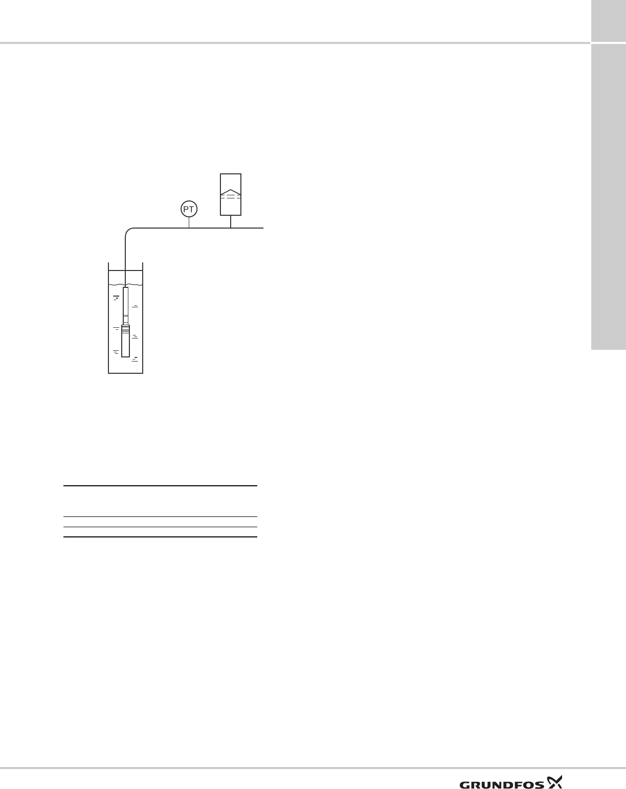
Signal relays
The table shows the function of the signal relays.
See also fig. 27.
Fig. 27 Terminals for signal relays (normal state, not
activated)
CU331SP installation
Mechanical installation
The individual CU331SP cabinet sizes are
characterized by their enclosures. The table in section
CU331SP technical data shows the relationship of
enclosure class and enclosure type.
Reception and storage
Check on receipt that the packaging is intact, and the
unit is complete. In case of damage during transport,
contact the transport company to file a claim.
Note that the CU331SP is delivered in a packaging
which is not suitable for outdoor storage.
Transportation and unpacking
The CU331SP must only be unpacked at the
installation site to prevent damage during the transport
to the site.
The packaging contains accessory bag(s),
documentation and the unit itself. See fig. 28.
Fig. 28 CU331SP packaging
Space requirements and air circulation
CU331SP units can be mounted side by side, but as a
sufficient air circulation is required for cooling these
requirements must be met:
• Sufficient free space above and below the
CU331SP
• Ambient temperature up to 122°F (50 °C)
• Hang the CU331SP directly on the wall, or fit it with
a back plate. See fig. 29.
Fig. 29 CU331SP hung directly on the wall or fitted with a
back plate
Required free space above and below the CU331SP:
For information about enclosure, see section Enclosure.
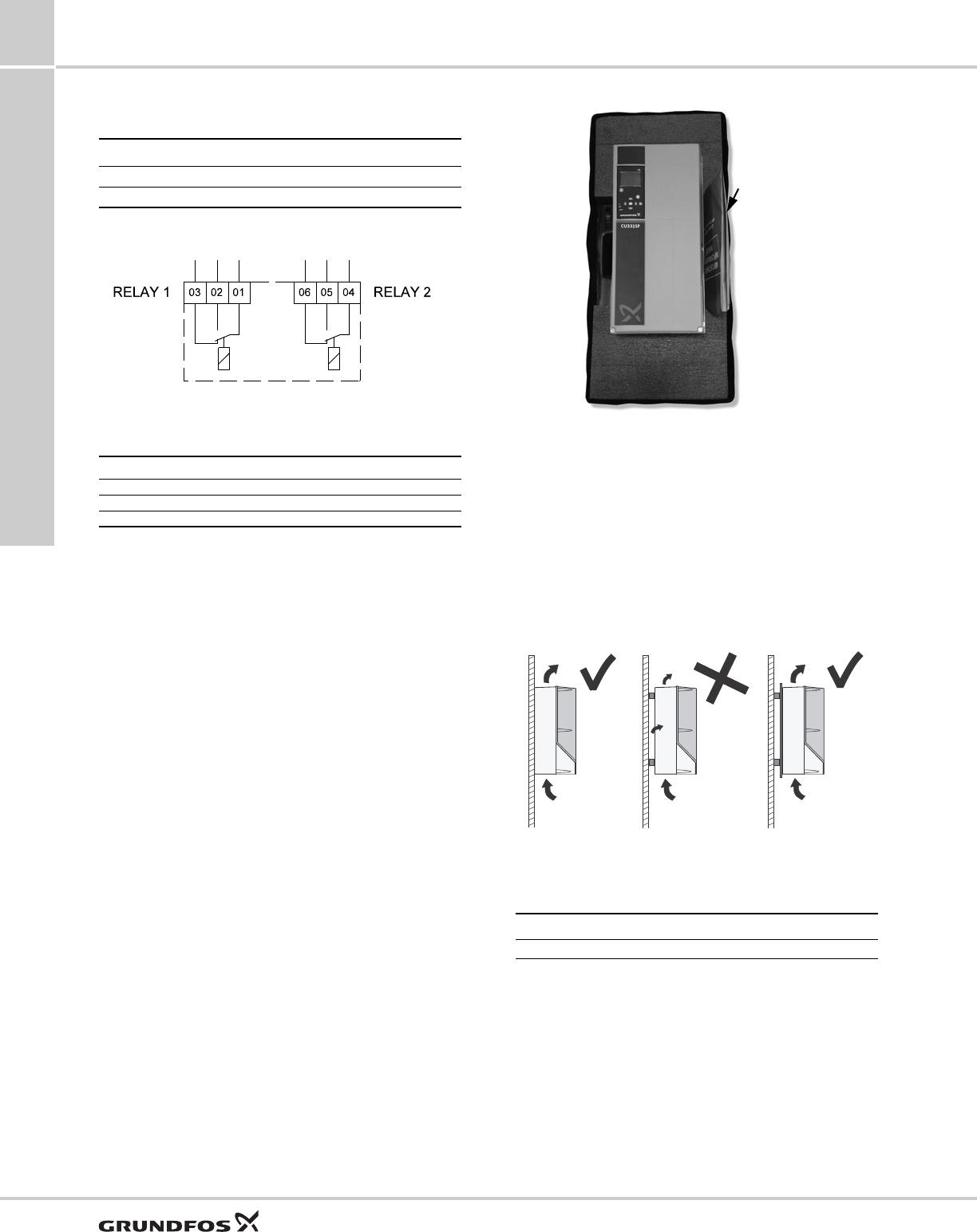
Mounting
The CU331SP must be mounted securely on a firm
surface. Ensure that screws are sized appropriately for
the weight of the CU331SP (approximately 60 lbs) and
anchored securely to the mounting surface.
1. Mark and drill holes. See fig. 30; also see
section Main dimensions and weight.
2. Fit the screws, but leave loose. Mount the
CU331SP, and tighten the four screws.
Type Function
Relay 1 • Pump running
Relay 2 •Alarm
TM03 8801 3407
Terminal Function
C1 C2 Common
NO 1 NO 2 Normally open contact
NC1 NC2 Normally closed contact
TM05 5990 4012
TM03 8859 2607
Enclosure Space [in (mm)]
B1 7.9 (200)
Accessory bag
CU331SP variable frequency drive
SQ, SQE, SQE-NE,
CU331SP 11
45
Fig. 30 Drilling holes for mounting
CU331SP electrical connection
Ensure the correct grounding and protection
procedures are used for the installation. Before the
electrical installation, ensure that the power supply and
other voltage inputs are switched off.
Electrical protection
Protection against electric shock, indirect contact
The leakage current to ground exceeds 3.5 mA, and a
reinforced ground connection is required.
Protective conductors must always have a yellow/
green (PE) or yellow/green/blue (PEN) color marking.
Instructions according to EN IEC 61800-5-1:
• The CU331SP must be stationary, installed
permanently and connected permanently to the
mains supply.
• The ground connection must be carried out with
duplicate protective conductors or with a single
reinforced protective conductor with a cross-section
of minimum AWG 7 (10 mm2).
Protection against short-circuit, fuses
The CU331SP and the supply system must be
protected against short-circuit.
Grundfos requires that the back-up fuses are used for
protection against short-circuit.
The CU331SP offers complete short-circuit protection
in case of a short-circuit on the motor output.
Additional protection
The leakage current to ground exceeds 3.5 mA.
If the CU331SP is connected to an electrical
installation where an earth leakage circuit breaker
(ELCB) is used as additional protection, the circuit
breaker must be of a type marked with the following
symbols:
Fig. 31 Circuit breaker type B
The total leakage current of all the electrical equipment
in the installation must be taken into account.
During start and in asymmetrical supply systems, the
leakage current can be higher than normal and may
cause the ELCB to trip.
Motor protection
The motor requires no external motor protection. The
CU331SP protects the motor against thermal
overloading and blocking.
Protection against overcurrent
The CU331SP has an internal overcurrent protection
for overload protection on the motor output.
Protection against mains voltage transients
The CU331SP is protected against mains voltage
transients according to EN 61800-3, second
environment.
Mains and motor connection
The supply voltage and frequency are marked on the
CU331SP nameplate. Make sure that the CU331SP is
suitable for the power supply of the installation site.
The maximum output voltage of the CU331SP is equal
to the input.
Example: if the supply voltage is rated at 208V choose
a 208V motor for operation.
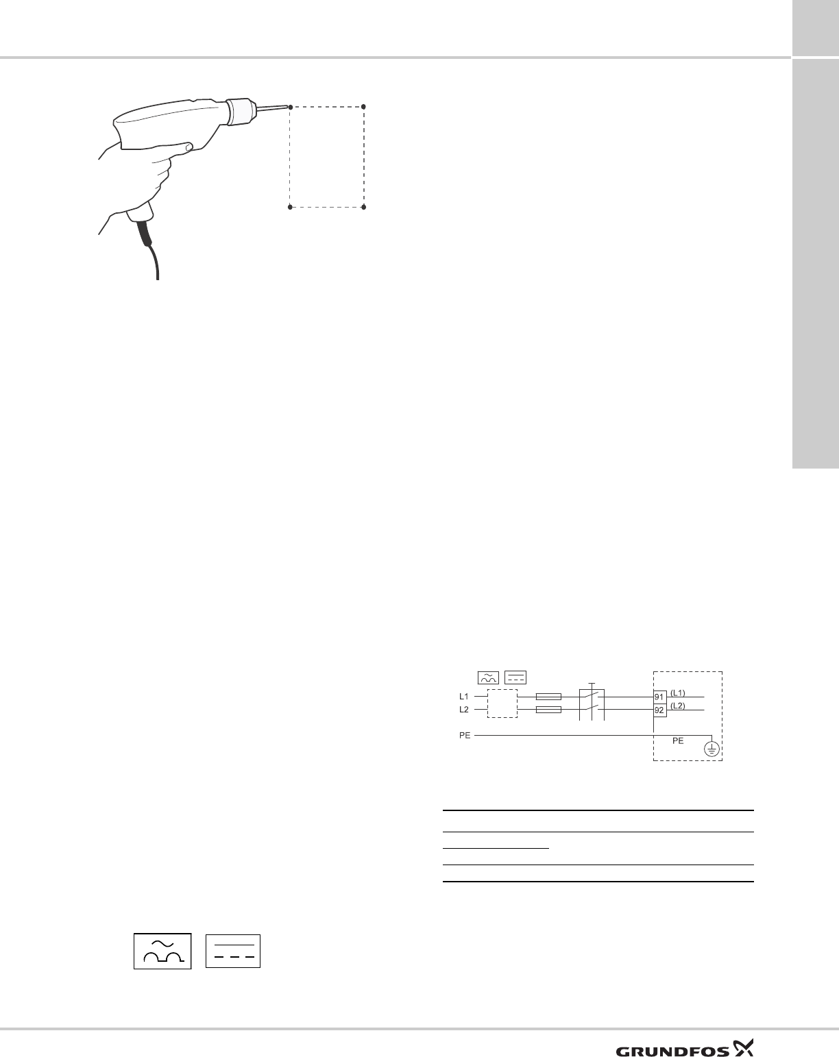
Mains switch
A mains switch can be installed before the CU331SP
according to local regulations. See fig. 32.
Wiring diagram
The wires in the terminal box must be as short as
possible. Excepted from this is the ground wire, which
must be so long that it is the last one to be
disconnected in case the cable is inadvertently pulled
out of the cable entry.
Fig. 32 CU331SP wiring diagram
For single-phase connection, use L1 and L2.
TM03 8860 2607
b
a
a
b
ELCB
TM05 5867 3912
Terminal Function
91 (L1) Single-phase supply
92 (L2)
95/99 (PE) Ground connection
CU331SP variable frequency drive
SQ, SQE, SQE-NE,
CU331SP
11
46
Mains connection
Check that mains voltage and frequency correspond to
the values on the nameplate of the CU331SP and the
motor.
1. Connect the ground wire to terminal 95 (PE). See
fig. 33.
2. Connect the power leads to the terminals 91 (L1),
92 (L2).
3. Fix the mains cable with a cable clamp.
Fig. 33 Mains connection
CU331SP drive is usable with 3-phase input power by
connecting leads to 91 (L1), 92 (L2), and 93 (L3).
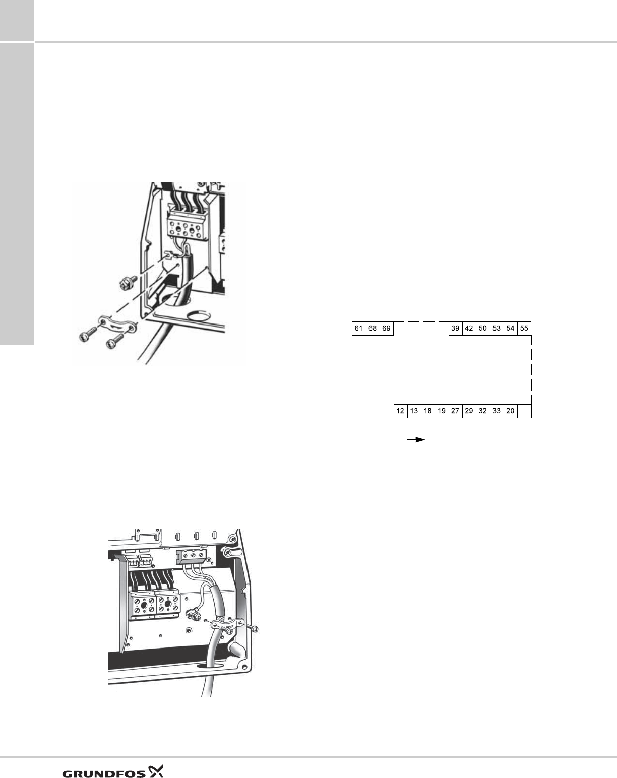
Motor connection
The motor cable must be screened for the CU331SP to
meet EMC requirements.
1. Connect the ground wire to terminal 99 (PE). See
fig. 34.
2. Connect the motor leads to the terminals 96 (U), 97
(V), 98 (W).
3. Fix the screened cable with a cable clamp.
Fig. 34 Motor connection
The cable screen must be exposed and in physical
contact with the mounting plate and clamp
11.1 Connecting the signal terminals
As a precaution, signal cables must be separated from
other groups by reinforced insulation in their entire
lengths.
If no external on/off switch is connected, short-circuit
terminals 18 and 20 using a short wire.
Connect the signal cables according to the guidelines
for good practice to ensure EMC-correct installation.
See section EMC-correct installation.
• Use screened signal cables with a conductor cross-
section of min. AWG 20 (0.5 mm2) and max. AWG
16 (1.5 mm2).
• Use a 3-conductor screened bus cable in new
systems.
Minimum connection, signal terminal
Operation is only possible when the terminals 18 and
20 are connected, for instance by means of an external
on/off switch or a short wire.
Fig. 35 Required minimum connection, signal terminal
TM03 9020 2807
TM03 9057 3207
Start/stop
GND
Jumper wire
CU331SP variable frequency drive
SQ, SQE, SQE-NE,
CU331SP 11
47
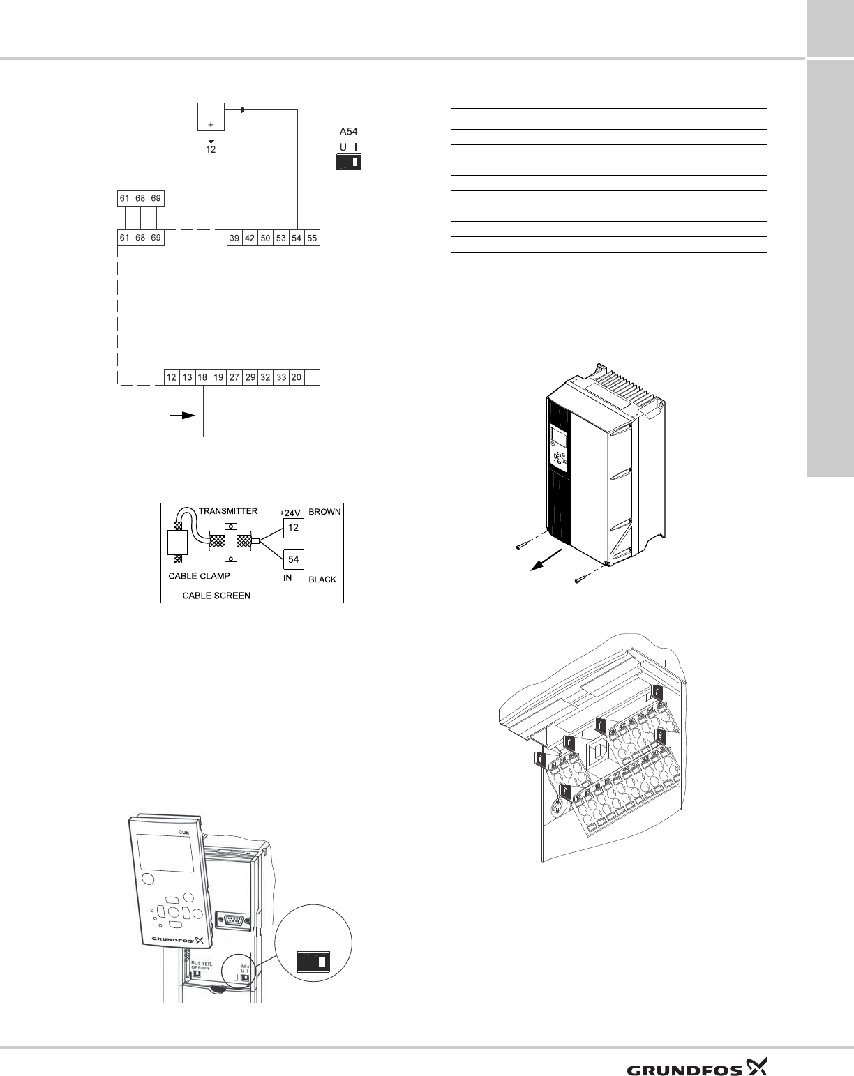
Fig. 36 Wiring diagram for CU331SP
Fig. 37 Sensor wiring diagram
Setting the analog input 54
The contact A54 is positioned behind the control panel
and is used for setting the signal type of the analog
input.
The factory setting of the inputs is voltage signal "U".
This setting must be changed to "I" prior to starting the
CU331SP. Be sure the power supply is switched off.
Remove the control panel to set the contact. See
fig. 38.
Fig. 38 Setting contact A54 to current signal "I"
Terminal key
The RS-485 screen must be connected to frame.
Access to signal terminals
All signal terminals are behind the terminal cover of the
CU331SP front. Remove the terminal cover as shown
in fig. 39.
Fig. 39 Access to signal terminals
Fig. 40 Signal terminals
TM05 5802 3913
TM05 6776 5112TM05 5803 3912
0/4-20 mA
Terminals
Sensor 1
GND
GND
+24 V out
Start/stop
RS-485 GND Y
RS-485 B
RS-485 A
Switch position
must be
changed to "I"
prior to startup
Jumper wire
UI
A54
Terminal Type Function
12 +24 V out Supply to sensor
18 DI 1 Digital input, start/stop
20 GND Common frame for digital inputs
55 GND Common frame for analog inputs
54 AI 2 Sensor input, sensor 1, 0/4-20 mA
61 RS-485 GND Y GENIbus, frame
68 RS-485 A GENIbus, signal A (+)
69 RS-485 B GENIbus, signal B (-)
TM03 9004 2807
TM03 9025 2807
CU331SP variable frequency drive
SQ, SQE, SQE-NE,
CU331SP
11
48
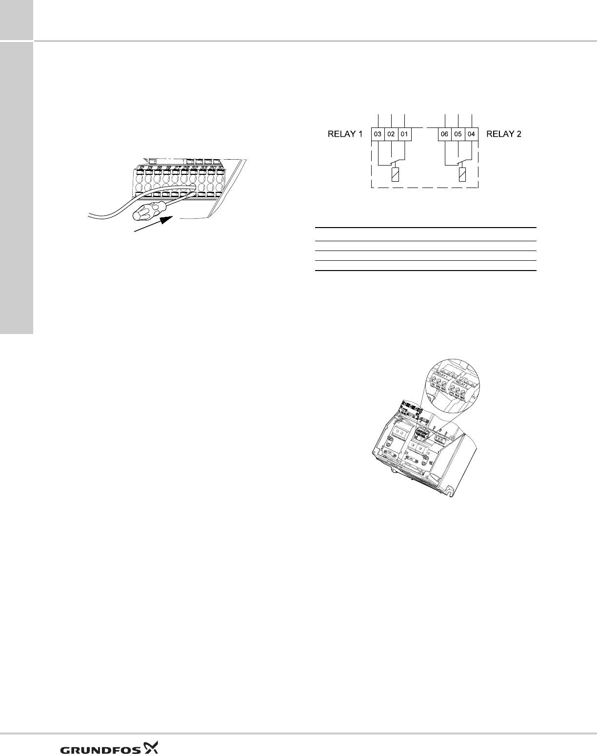
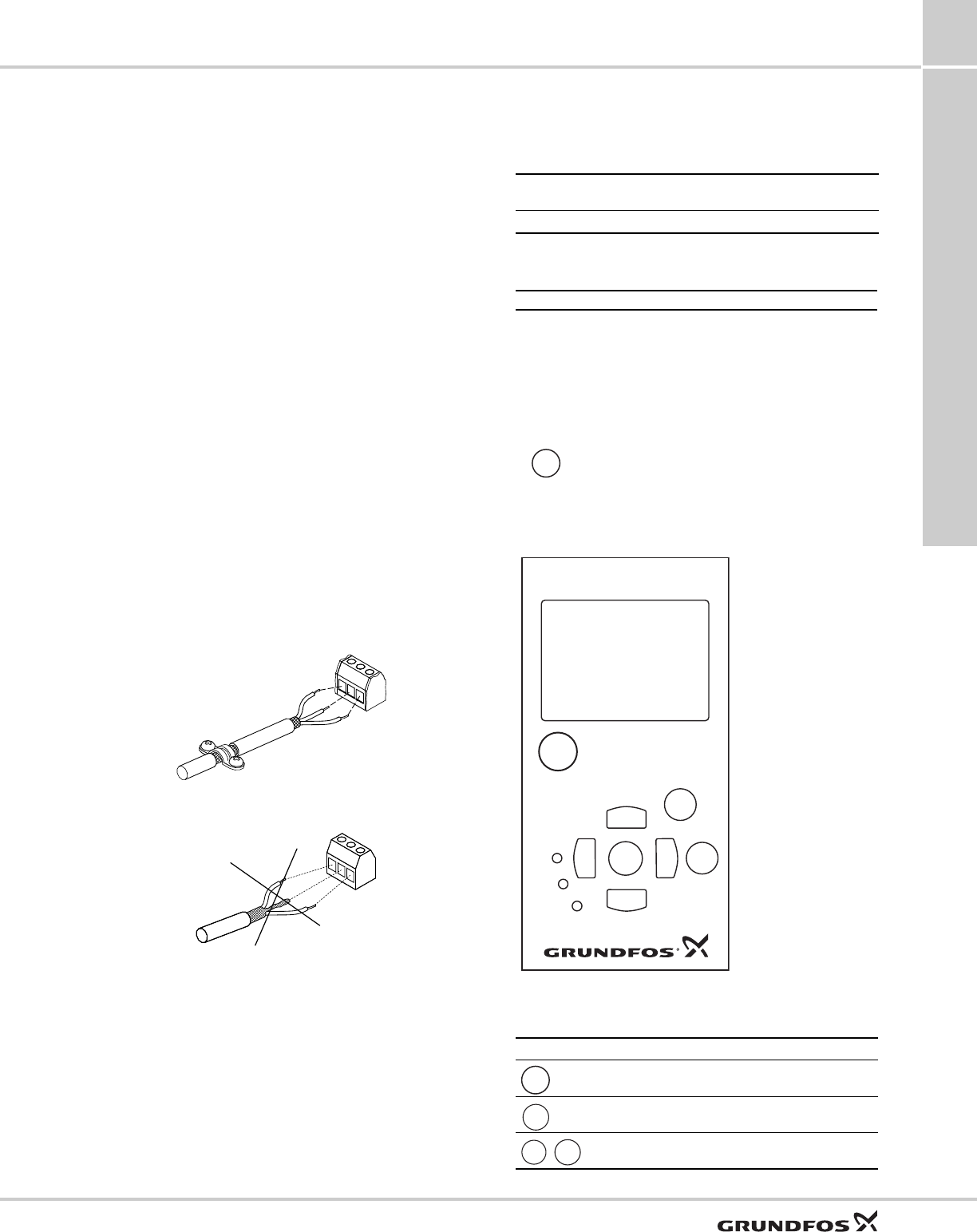
Fitting the conductor
1. Remove the insulation at a length of
0.35 to 0.40 inches (9 to 10 mm).
2. Insert a screwdriver with a tip of maximum
0.015 X 0.1 in (0.4 X 2.5 mm) into the square hole.
3. Insert the conductor into the corresponding round
hole. Remove the screwdriver. The conductor is
now fixed in the terminal.
Fig. 41 Fitting the conductor into the signal terminal
Connecting the signal relays
As a precaution, signal cables must be separated from
other groups by reinforced insulation in their entire
lengths.
Fig. 42 Terminals for signal relays (normal state, not
activated)
Signal relay
The signal relays on the CU331SP are predefined as
follows:
Relay 1: Pump running
Relay 2: Alarm
Fig. 43 Terminals for relay connection
TM03 9026 2807
TM03 8801 2507
Terminal Function
C 1 C 2 Common
NO 1 NO 2 Normally open contact
NC 1 NC 2 Normally closed contact
TM03 9008 2807
C 1
NC 1
NO 1
NC 2
NO 2
C2
CU331SP variable frequency drive
SQ, SQE, SQE-NE,
CU331SP 11
49
EMC-correct installation
This section gives guidelines for good practice when
installing the CU331SP. Follow these guidelines to
meet EN 61800-3, first environment.
• Use only motor and signal cables with a braided
metal screen in applications without output filter.
• There are no special requirements to supply cables,
apart from local requirements.
• Leave the screen as close to the connecting
terminals as possible. See fig. 44.
• Avoid terminating the screen by twisting the ends.
See fig. 45. Use cable clamps or EMC screwed
cable entries instead.
• Connect the screen to frame at both ends for both
motor and signal cables. If the controller has no
cable clamps, connect only the screen to the
CU331SP.
• Avoid unscreened motor and signal cables in
electrical cabinets with variable frequency drives.
• Make the motor cable as short as possible in
applications without output filter to limit the noise
level and minimize leakage currents.
• Screws for frame connections must always be
tightened whether a cable is connected or not.
• Keep main cables, motor cables and signal cables
separated in the installation, if possible.
Other installation methods may give similar EMC
results if the above guidelines for good practice are
followed.
Fig. 44 Example of stripped cable with screen
Fig. 45 Do not twist the screen ends
Line disturbance and transient protection
To protect itself from AC line voltage disturbances, the
CU331SP monitors the input power supply and
interrupts drive operation in the event of phase loss or
imbalance. Transients on the AC line are suppressed
by MOVs as well as zener diodes for extreme
transients. The CU331SP meets VDE 0160 (European
standard - 2.3 x line voltage for 1.3 msec) for transient
protection.
RFI filters
To meet the EMC requirements, the CU331SP comes
with the following types of built-in radio frequency
interference filter (RFI).
*Single-phase input - three-phase output.
Description of RFI filter types
RFI filter types are according to EN61800-3
Control panel
The on/off button on the control panel does not
disconnect the CU331SP from the power supply and
must therefore not be used as a safety switch.
The control panel is used for local setting of the
CU331SP. The functions available are preset in the
CU331SP.
Fig. 46 Control panel of the CU331SP
Editing buttons
TM02 1325 0901TM03 8812 2507
Voltage Typical shaft power P2 RFI filter type
1 x 200-240 V * 1.5 - 10 hp C1
C1: For use in domestic areas.
The On/Off button has the highest priority.
In "Off" condition, pump operation is not
possible.
TM03 8719 2507
Button Function
Makes the pump ready for operation/starts and stops
the pump.
Saves changed values, resets alarms and expands the
value field.
Changes values in the value field.
On/On/
Off
+
-
CU
CUE
>
>
>
>
OK
On/
On/
Off
On
On
Off
Alarm
Alarm
On/
On/
Off
OK
+
-
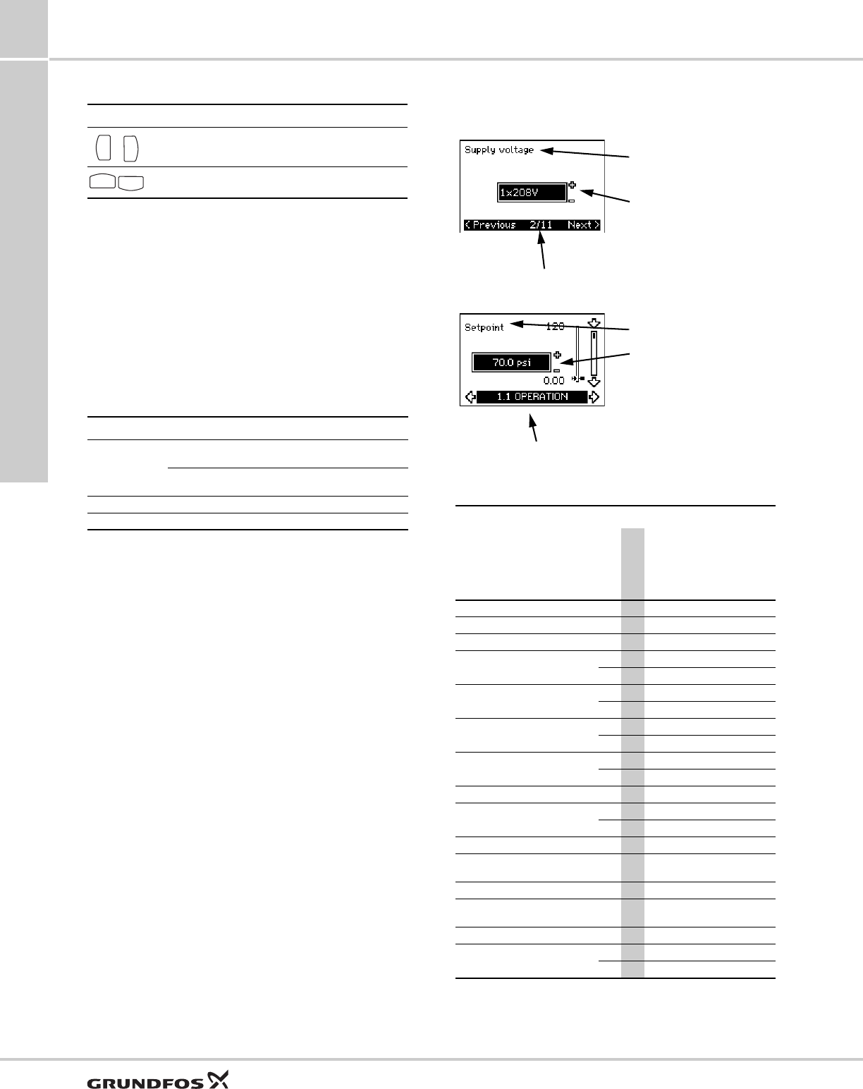
CU331SP variable frequency drive
SQ, SQE, SQE-NE,
CU331SP
11
50
Navigating buttons
Adjusting the display contrast
Press OK and + for darker display.
Press OK and - for brighter display.
Button lock
To lock the buttons on the panel press and hold the up
and down arrows simultaneously.
Indicator lights
The operating condition of the pump is indicated by the
indicator lights on the front of the control panel. See
fig. 46.
The table shows the function of the indicator lights.
Displays, general terms
Figures 47 and 48 show the general terms of the
display.
Fig. 47 Example of display in the start-up guide
Fig. 48 Example of display in the user menu
Warning and alarm list
1) In case of an alarm, the CU331SP will change the
operating mode depending on the pump type.
2) Warning is reset in display 3.20.
Button Function
Navigates from one menu to another. When the menu
is changed, the display shown will always be the top
display of the new menu.
Navigates up and down in the individual menu.
Indicator light Function
On (green)
The pump is running or has been stopped by a stop
function.
If flashing, the pump has been stopped by the user
(CU331SP menu), external start/stop or bus.
Off (orange) The pump has been stopped with the on/off button.
Alarm (red) Indicates an alarm or a warning.
>
>
>
>
Code and display text
Status
Operating
mode Resetting
Warning
Alarm
Locked alarm
1 Too high leakage current ●Stop Man.
2 Mains phase failure ●Stop Aut.
3 External fault ●Stop Man.
16 Other fault
● Stop Aut.
●Stop Man.
32 Overvoltage
●-Aut.
●Stop Aut.
40 Undervoltage
●-Aut.
●Stop Aut.
48 Overload
●Stop Aut.
●Stop Man.
49 Overload ●Stop Aut.
55 Overload
●-Aut.
●Stop Aut.
57 Dry running ●Stop Aut.
64 Too high CU331SP
temperature ●Stop Aut.
89 Sensor 1 outside range ●1) Aut.
96 Setpoint signal outside
range ●1) Aut.
155 Inrush fault ●Stop Aut.
241 Motor phase failure
●-Aut.
●Stop Aut.
Display name
Current display / total number
Value field
Display name
Display number, menu name
Value field
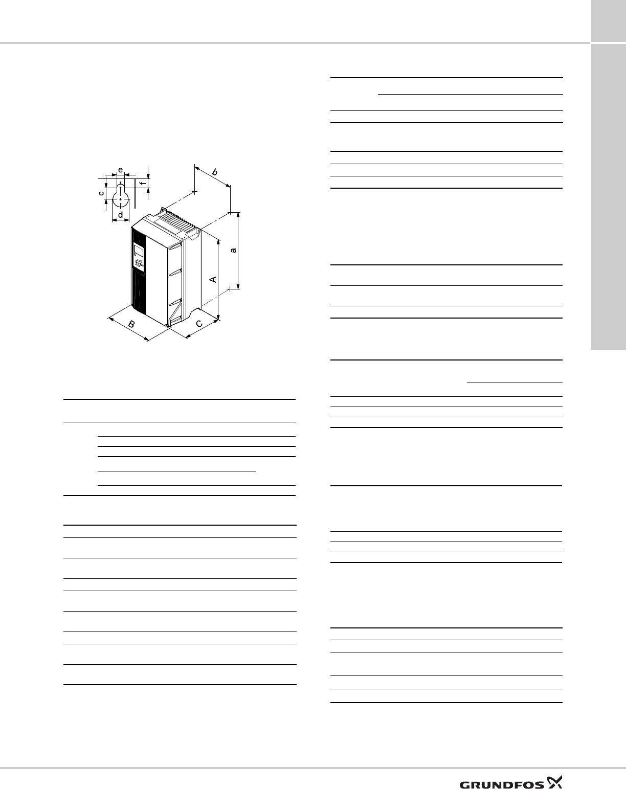
CU331SP variable frequency drive
SQ, SQE, SQE-NE,
CU331SP 11
51
CU331SP technical data
Enclosure
All CU331SP enclosures are size B1.
The enclosure rating can be either IP 55 / TYPE 12 or
IP 66 / TYPE 4X.
Main dimensions and weight
Fig. 49 Enclosure B1
1) The dimensions are maximum height, width and depth.
Surroundings
The CU331SP comes in a packaging which is not
suitable for outdoor storage.
Terminal tightening torques
Cable length
Fuses and cable cross-section
Always comply with national and local regulations as to
cable cross-sections.
Cable cross-section to signal terminals
Non-UL fuses and conductor cross-
section to mains and motor
1) Screened motor cable, unscreened supply cable.
UL fuses and conductor cross-section to
mains and motor
1) Screened motor cable, unscreened supply cable.
Inputs and outputs
Mains supply (L1, L2)
Do not use the power supply for switching the
CU331SP on and off.
TM03 9002 2807
Enclo-
sure Height
[in] Width
[in] Depth
[in]
B1
AaBbC
18.9 17.9 9.5 8.3 10.2
Screw holes [in] Weight
[lbs]
cdef
0.47 0.75 0.35 0.35 50.7
Relative humidity 5-95 % RH
Ambient temperature Max. 122 °F
(50 °C)
Average ambient temperature over 24 hours Max. 113 °F
(45 °C)
Minimum ambient temperature at full operation 32 °F (0 °C)
Minimum ambient temperature at reduced
operation 14 °F (-10 °C)
Temperature during storage and transportation -13 to 150 °F
(-25 to 65 °C)
Storage duration Max. 6 months
Maximum altitude above sea level without
performance reduction 3280 ft (1000 m)
Maximum altitude above sea level with
performance reduction 9840 ft (3000 m)
Enclosure Tightening torque [ft-lb]
Mains Motor Earth Relay
B1 1.3 1.3 2.2 0.4
Maximum length, screened motor cable 500 ft (152 m)
Maximum length, unscreened motor cable 1000 ft (305 m)
Maximum length, signal cable 1000 ft (305 m)
Maximum cable cross-section to signal terminals,
rigid conductor AWG 14
Maximum cable cross-section to signal terminals,
flexible conductor AWG 18
Minimum cable cross-section to signal terminals AWG 20
Typical shaft
power P2
[Hp]
Maximum
fuse size
[A]
Fuse
type
Maximum conductor
cross section1
[AWG] [mm2]
240gG710
340gG710
580gG710
Typical shaft
power P2
[Hp]
Maximum
fuse size
[A]
Bussmann
RK1
Maximum
conductor
cross section1
[AWG}
240KTN-R407
340KTN-R407
580KTN-R807
Supply voltage 200-240 V ± 10 %
Supply frequency 60 Hz
Maximum temporary imbalance
between phases 3 % of rated value
Leakage current to earth > 3.5 mA
Number of cut-ins Max. 1 time/min.
CU331SP variable frequency drive
SQ, SQE, SQE-NE,
CU331SP
11
52
Motor output (U, V, W)
1) Output voltage in % of supply voltage.
RS-485 GENIbus connection
The RS-485 circuit is functionally separated from other
central circuits and galvanically separated from the
supply voltage (PELV).
Digital inputs
All digital inputs are galvanically separated from the
supply voltage (PELV) and other high-voltage
terminals.
Signal relays
1) IEC 60947, parts 4 and 5.
The relay contacts are galvanically separated from
other circuits by reinforced insulation (PELV).
Analog input
1) The factory setting is voltage signal "U".
All analog inputs are galvanically separated from the
supply voltage (PELV) and other high-voltage
terminals.
Sound pressure level
The sound pressure of the CU331SP is maximum 70
dB(A).
The sound pressure level of a motor controlled by a
Variable frequency drive may be higher than that of a
corresponding motor which is not controlled by a
variable frequency drive.
Output voltage 0-100 % 1)
Output frequency 0-60 Hz
Switching on output Not recommended
Terminal number 68 (A), 69 (B), 61 GND (Y)
Terminal number 18
Voltage level 0-24 VDC
Voltage level, open contact > 19 VDC
Voltage level, closed contact < 14 VDC
Maximum voltage on input 28 VDC
Input resistance, RiApprox. 4 kΩ
Relay 01, terminal number 1 (C), 2 (NO), 3 (NC)
Relay 02, terminal number 4 (C), 5 (NO), 6 (NC)
Maximum terminal load (AC-1) 1) 240 VAC, 2 A
Maximum terminal load (AC-15) 1) 240 VAC, 0.2 A
Maximum terminal load (DC-1) 1) 50 VDC, 1 A
Minimum terminal load 24 V DC 10 mA
24 V AC 20 mA
CCommon
NO Normally open
NC Normally closed
Terminal number 54
Current signal A54 = "I" 1)
Current range 0-20, 4-20 mA
Input resistance, RiApprox. 200 Ω
Maximum current 30 mA
Maximum fault, terminals 53, 54 0.5 % of full scale
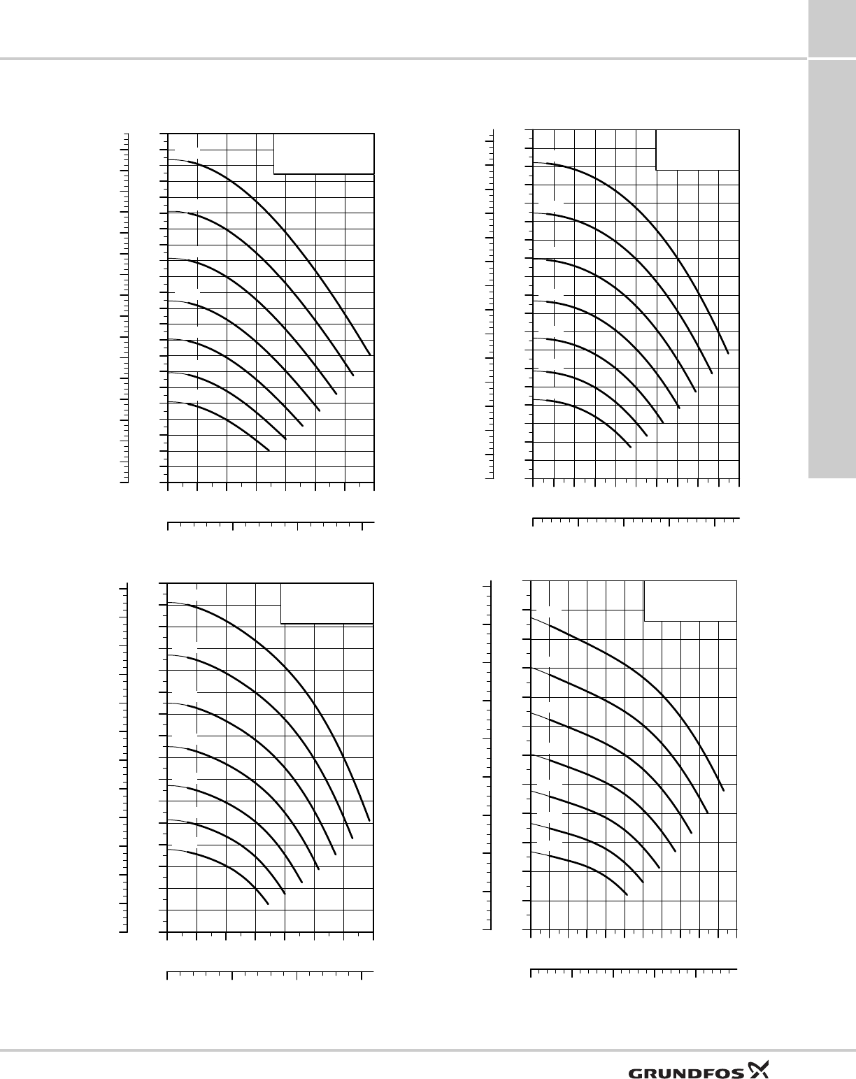
CU331SP variable frequency drive
SQ, SQE, SQE-NE,
CU331SP 11
53
CU331SP curve charts
TM05 6410 5012
TM05 6412 5012
0 1 2 3 4 5 6 7
Q [US GPM]
0
50
100
150
200
250
300
350
400
450
500
550
600
650
700
750
800
850
900
950
1000
1050
[ft]
H
0.0 0.5 1.0 Q [m³/h]
0
20
40
60
80
100
120
140
160
180
200
220
240
260
280
300
320
[m]
H
5S20-39ds
60 Hz
30 Hz
35 Hz
40 Hz
45 Hz
50 Hz
55 Hz
0 2 4 6 8 10 12 14
Q [US GPM]
0
50
100
150
200
250
300
350
400
450
500
550
600
650
700
750
[ft]
H
0 1 2 Q [m³/h]
0
20
40
60
80
100
120
140
160
180
200
220
[m]
H
10S20-27
60 Hz
30 Hz
35 Hz
40 Hz
45 Hz
50 Hz
55 Hz
TM05 6411 5012
TM05 6413 5012
0 1 2 3 4 5 6 7 8 9 10
Q [US GPM]
0
50
100
150
200
250
300
350
400
450
500
550
600
650
700
750
800
850
900
[ft]
H
0.0 0.5 1.0 1.5 Q [m³/h]
0
20
40
60
80
100
120
140
160
180
200
220
240
260
[m]
H
7S20-32
60 Hz
30 Hz
35 Hz
40 Hz
45 Hz
50 Hz
55 Hz
0 2 4 6 8 10 12 14 16 18 20 22
Q [US GPM]
0
50
100
150
200
250
300
350
400
450
500
550
[ft]
H
0 1 2 3 Q [m³/h]
0
20
40
60
80
100
120
140
160
[m]
H
16S20-18
60 Hz
30 Hz
35 Hz
40 Hz
45 Hz
50 Hz
55 Hz
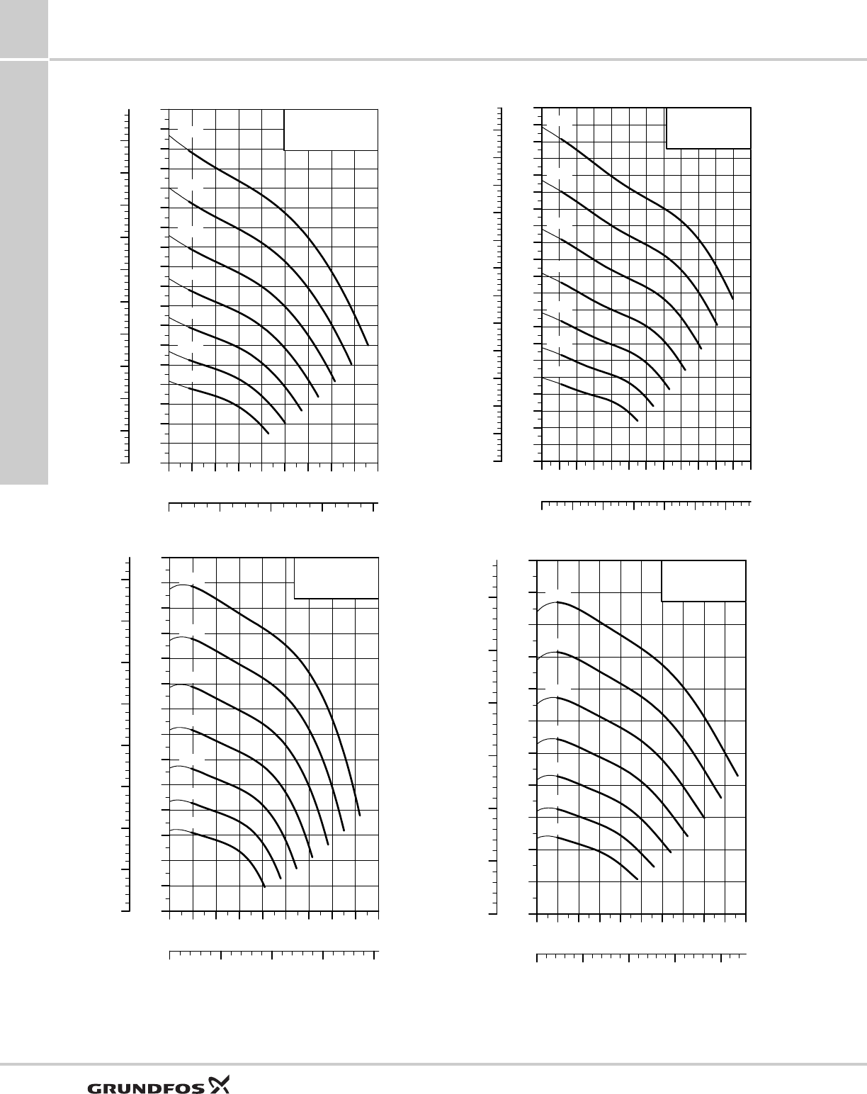
CU331SP variable frequency drive
SQ, SQE, SQE-NE,
CU331SP
11
54
TM05 6414 5012
TM05 6416 5012
0 4 8 12 16 20 24 28 32 36
Q [US GPM]
0
20
40
60
80
100
120
140
160
180
200
220
240
260
280
300
320
340
[ft]
H
0 2 4 6 Q [m³/h]
0
10
20
30
40
50
60
70
80
90
100
[m]
H
25S20-11
60 Hz
30 Hz
35 Hz
40 Hz
45 Hz
50 Hz
55 Hz
0 10 20 30 40 50 60 70 80 90
Q [US GPM]
0
10
20
30
40
50
60
70
80
90
100
110
120
130
[ft]
H
0 5 10 15 Q [m³/h]
0
5
10
15
20
25
30
35
40
[m]
H
60S20-4
60 Hz
30 Hz
35 Hz
40 Hz
45 Hz
50 Hz
55 Hz
TM05 6415 5012
TM05 6417 5012
0 5 10 15 20 25 30 35 40 45 50 55 60
Q [US GPM]
0
10
20
30
40
50
60
70
80
90
100
110
120
130
140
150
160
170
180
190
200
[ft]
H
0 2 4 6 8 10 Q [m³/h]
0
5
10
15
20
25
30
35
40
45
50
55
60
[m]
H
40S20-7
60 Hz
30 Hz
35 Hz
40 Hz
45 Hz
50 Hz
55 Hz
0 10 20 30 40 50 60 70 80 90 100
Q [US GPM]
0
10
20
30
40
50
60
70
80
90
100
[ft]
H
0 5 10 15 Q [m³/h]
0
5
10
15
20
25
30
[m]
H
75S20-3
60 Hz
30 Hz
35 Hz
40 Hz
45 Hz
50 Hz
55 Hz
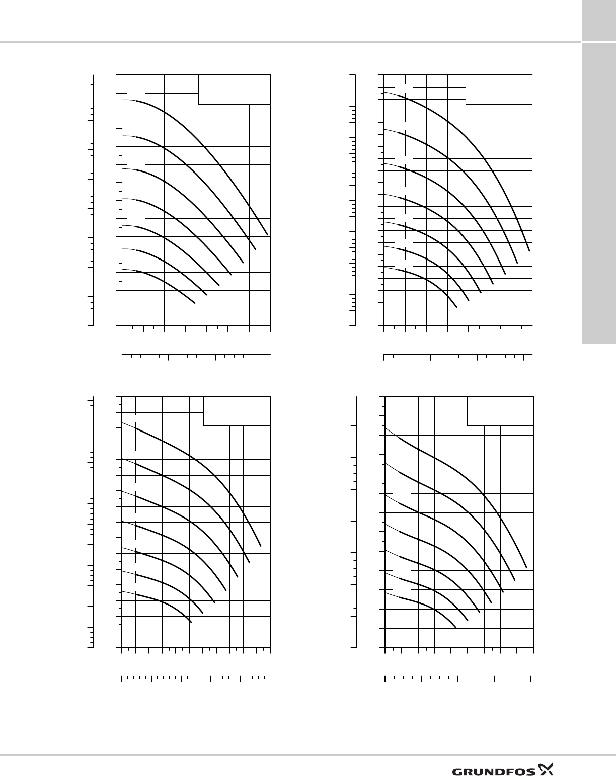
CU331SP variable frequency drive
SQ, SQE, SQE-NE,
CU331SP 11
55
TM05 6418 5012
TM05 6420 5012
0 1 2 3 4 5 6 7
Q [US GPM]
0
100
200
300
400
500
600
700
800
900
1000
1100
1200
1300
[ft]
H
0.0 0.5 1.0 Q [m³/h]
0
50
100
150
200
250
300
350
400
[m]
H
5S30-48ds
60 Hz
30 Hz
35 Hz
40 Hz
45 Hz
50 Hz
55 Hz
0 2 4 6 8 10 12 14 16 18 20 22
Q [US GPM]
0
50
100
150
200
250
300
350
400
450
500
550
600
650
700
750
[ft]
H
0 1 2 3 Q [m³/h]
0
20
40
60
80
100
120
140
160
180
200
220
[m]
H
16S30-24
60 Hz
30 Hz
35 Hz
40 Hz
45 Hz
50 Hz
55 Hz
TM05 6419 5012
TM05 6421 5012
0 2 4 6 8 10 12 14
Q [US GPM]
0
50
100
150
200
250
300
350
400
450
500
550
600
650
700
750
800
850
900
950
1000
[ft]
H
0 1 2 Q [m³/h]
0
20
40
60
80
100
120
140
160
180
200
220
240
260
280
300
[m]
H
10S30-34
60 Hz
30 Hz
35 Hz
40 Hz
45 Hz
50 Hz
55 Hz
0 4 8 12 16 20 24 28 32 36
Q [US GPM]
0
40
80
120
160
200
240
280
320
360
400
440
480
[ft]
H
0 2 4 6 Q [m³/h]
0
20
40
60
80
100
120
140
[m]
H
25S30-15
60 Hz
30 Hz
35 Hz
40 Hz
45 Hz
50 Hz
55 Hz
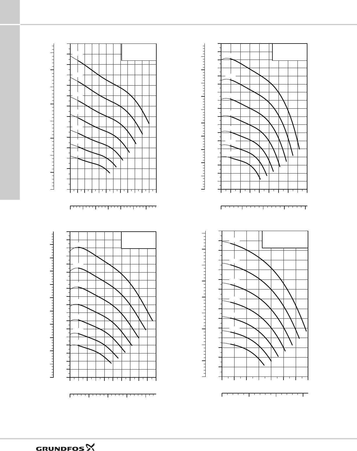
CU331SP variable frequency drive
SQ, SQE, SQE-NE,
CU331SP
11
56
TM05 6422 5012
TM05 6424 5012
0 5 10 15 20 25 30 35 40 45 50 55 60
Q [US GPM]
0
20
40
60
80
100
120
140
160
180
200
220
240
260
[ft]
H
0 2 4 6 8 10 Q [m³/h]
0
10
20
30
40
50
60
70
80
[m]
H
40S30-9
60 Hz
30 Hz
35 Hz
40 Hz
45 Hz
50 Hz
55 Hz
0 10 20 30 40 50 60 70 80 90 100
Q [US GPM]
0
10
20
30
40
50
60
70
80
90
100
110
120
130
140
150
160
170
[ft]
H
0 5 10 15 Q [m³/h]
0
5
10
15
20
25
30
35
40
45
50
[m]
H
75S30-5
60 Hz
30 Hz
35 Hz
40 Hz
45 Hz
50 Hz
55 Hz
TM05 6423 5012TM05 6425 5012
0 10 20 30 40 50 60 70 80 90
Q [US GPM]
0
10
20
30
40
50
60
70
80
90
100
110
120
130
140
150
160
170
[ft]
H
0 5 10 15 Q [m³/h]
0
5
10
15
20
25
30
35
40
45
50
[m]
H
60S30-5
60 Hz
30 Hz
35 Hz
40 Hz
45 Hz
50 Hz
55 Hz
0 2 4 6 8 10 12 14
Q [US GPM]
0
100
200
300
400
500
600
700
800
900
1000
1100
1200
1300
1400
[ft]
H
0 1 2 Q [m³/h]
0
50
100
150
200
250
300
350
400
[m]
H
10S50-48ds
60 Hz
30 Hz
35 Hz
40 Hz
45 Hz
50 Hz
55 Hz
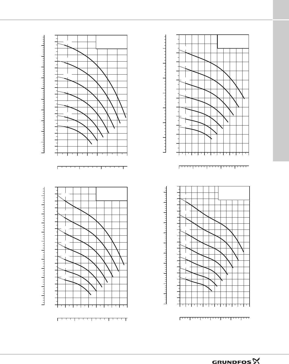
CU331SP variable frequency drive
SQ, SQE, SQE-NE,
CU331SP 11
57
TM05 6426 5012TM05 6428 5012
0 2 4 6 8 10 12 14
Q [US GPM]
0
100
200
300
400
500
600
700
800
900
1000
1100
1200
1300
1400
1500
1600
1700
[ft]
H
0 1 2 Q [m³/h]
0
50
100
150
200
250
300
350
400
450
500
[m]
H
10S50-58
60 Hz
30 Hz
35 Hz
40 Hz
45 Hz
50 Hz
55 Hz
0 4 8 12 16 20 24 28 32 36
Q [US GPM]
0
50
100
150
200
250
300
350
400
450
500
550
600
650
700
750
800
[ft]
H
0 2 4 6 Q [m³/h]
0
20
40
60
80
100
120
140
160
180
200
220
240
[m]
H
25S50-26
60 Hz
30 Hz
35 Hz
40 Hz
45 Hz
50 Hz
55 Hz
TM05 6427 5012TM05 6429 5012
0 2 4 6 8 10 12 14 16 18 20 22
Q [US GPM]
0
100
200
300
400
500
600
700
800
900
1000
1100
1200
[ft]
H
0 1 2 3 Q [m³/h]
0
50
100
150
200
250
300
350
[m]
H
16S50-38
60 Hz
30 Hz
35 Hz
40 Hz
45 Hz
50 Hz
55 Hz
0 5 10 15 20 25 30 35 40 45 50 55 60
Q [US GPM]
0
20
40
60
80
100
120
140
160
180
200
220
240
260
280
300
320
340
360
[ft]
H
0 2 4 6 8 10 Q [m³/h]
0
10
20
30
40
50
60
70
80
90
100
110
[m]
H
40S50-12
60 Hz
30 Hz
35 Hz
40 Hz
45 Hz
50 Hz
55 Hz
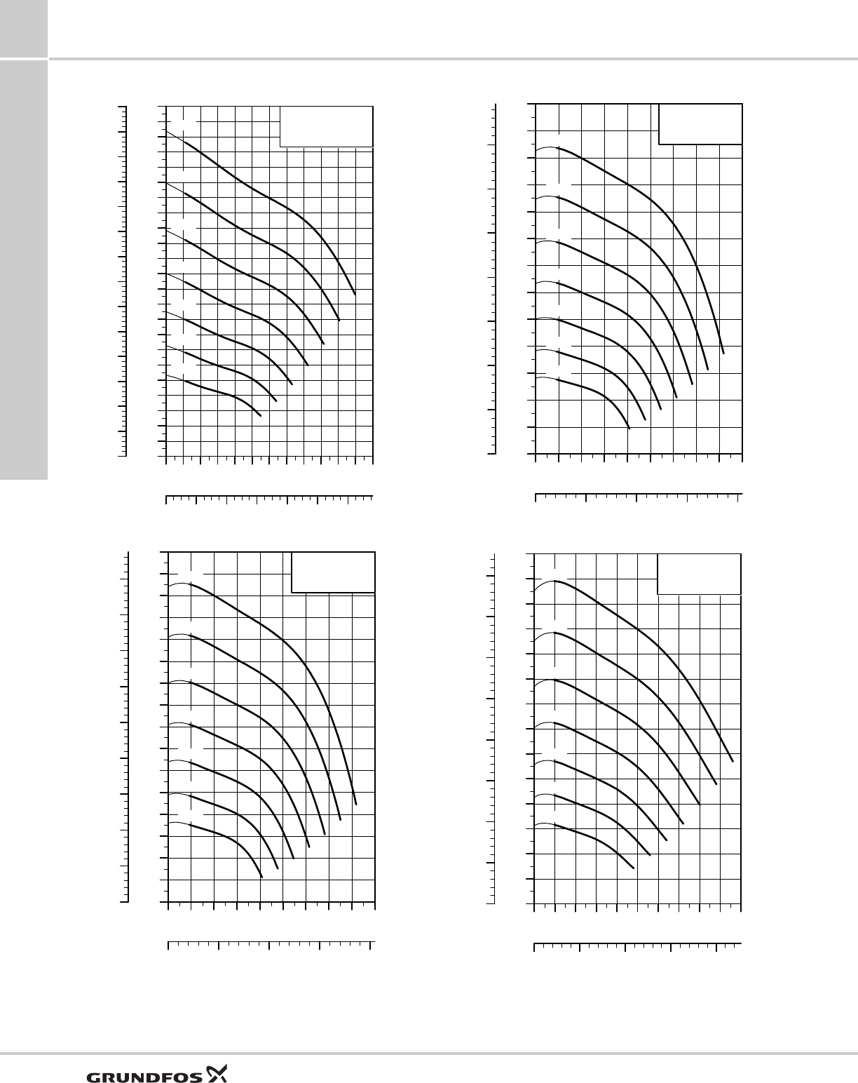
CU331SP variable frequency drive
SQ, SQE, SQE-NE,
CU331SP
11
58
TM05 6430 5012
TM05 6432 5012
0 5 10 15 20 25 30 35 40 45 50 55 60
Q [US GPM]
0
20
40
60
80
100
120
140
160
180
200
220
240
260
280
300
320
340
360
380
400
420
440
[ft]
H
0 2 4 6 8 10 Q [m³/h]
0
10
20
30
40
50
60
70
80
90
100
110
120
130
[m]
H
40S50-15
60 Hz
30 Hz
35 Hz
40 Hz
45 Hz
50 Hz
55 Hz
0 10 20 30 40 50 60 70 80 90
Q [US GPM]
0
20
40
60
80
100
120
140
160
180
200
220
240
260
280
300
[ft]
H
0 5 10 15 Q [m³/h]
0
10
20
30
40
50
60
70
80
90
[m]
H
60S50-9
60 Hz
30 Hz
35 Hz
40 Hz
45 Hz
50 Hz
55 Hz
TM05 6431 5012
TM05 6433 5012
0 10 20 30 40 50 60 70 80 90
Q [US GPM]
0
20
40
60
80
100
120
140
160
180
200
220
240
[ft]
H
0 5 10 15 Q [m³/h]
0
10
20
30
40
50
60
70
[m]
H
60S50-7
60 Hz
30 Hz
35 Hz
40 Hz
45 Hz
50 Hz
55 Hz
0 10 20 30 40 50 60 70 80 90 100
Q [US GPM]
0
20
40
60
80
100
120
140
160
180
200
220
240
260
[ft]
H
0 5 10 15 Q [m³/h]
0
10
20
30
40
50
60
70
80
[m]
H
75S50-8
60 Hz
30 Hz
35 Hz
40 Hz
45 Hz
50 Hz
55 Hz
Accessories
SQ, SQE, SQE-NE,
CU331SP 12
59
12. Accessories
CU331SP Constant Pressure
Drive Kits (with sensor)
CU 301 Constant Pressure System
CU 300 Status Box & R100
SQ, SQE flow sleeves
TM05 5801 4012
Enclosure type NEMA Hp Input Ph Input volts Product number Approx.
ship wt.
[lbs]
Indoor Type 12
2 1 200 - 240 98370277 60
3 1 200 - 240 98370280 60
5 1 200 - 240 98370304 60
Outdoor Type 4X
2 1 200 - 240 98370279 60
3 1 200 - 240 98370301 60
5 1 200 - 240 98370305 60
TM04 7509 2110
Description Product number
Constant Pressure Kit (CU 301 and Transducer) 96438895
TM04 7508 2110
Description Product number
CU300 Status Box 96422776
Description Product number
R100 (for wireless infrared communication with the
CU 301 / CU 300) 96615297
TM01 3292 3798
Description Product number
SQ, SQE flow sleeve, complete 98148594
55050
88
650 100
50210
250
max. ø100
ø90
Further product documentation
SQ, SQE, SQE-NE,
CU331SP
13
60
13. Further product documentation
WebCAPS WebCAPS is a Web-based Computer Aided Product
Selection program available on www.grundfos.com.
WebCAPS contains detailed information on more than
185,000 Grundfos products in more than 20
languages.
In WebCAPS, all information is divided into 6 sections:
• Catalog
• Literature
• Service
• Sizing
• Replacement
• CAD drawings.
Catalog
This section is based on fields of application and pump types,
and contains
• technical data
• curves (QH, Eta, P1, P2, etc) which can be adapted to the
density and viscosity of the pumped liquid and show the
number of pumps in operation
• product photos
• dimensional drawings
• wiring diagrams
• quotation texts, etc.
Literature
In this section you can access all the latest documents of a given
pump, such as
• product guides
• installation and operating instructions
• service documentation, such as Service kit catalog
and Service kit instructions
• quick guides
• product brochures, etc.
Service
This section contains an easy-to-use interactive service catalog.
Here you can find and identify service parts of both existing and
discontinued Grundfos pumps.
Furthermore, this section contains service videos showing you
how to replace service parts.
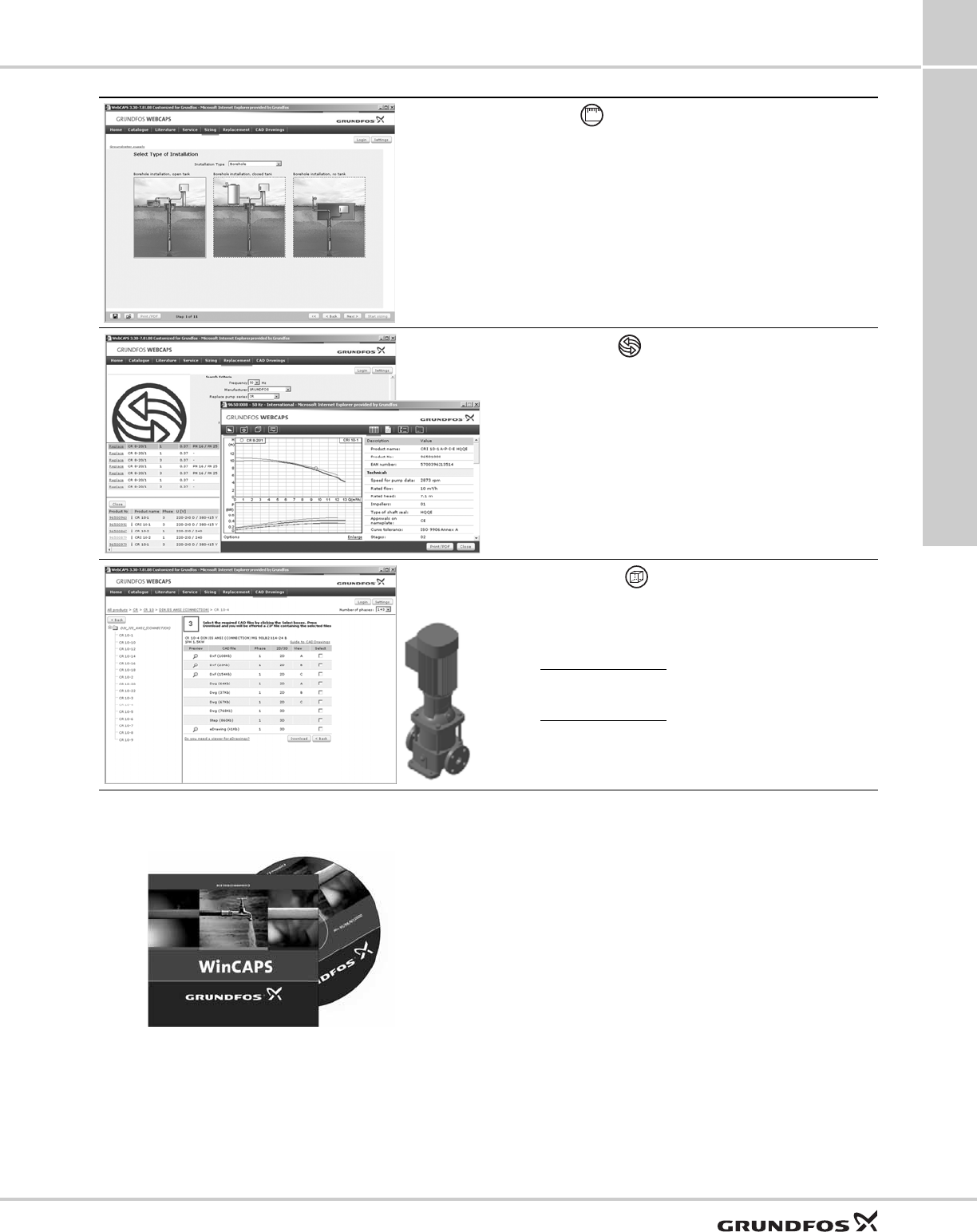
Further product documentation
SQ, SQE, SQE-NE,
CU331SP 13
61
WinCAPS
Fig. 50 WinCAPS CD-ROM
WinCAPS is a Windows-based Computer Aided
Product Selection program containing detailed
information on more than 185,000 Grundfos products
in more than 20 languages.
The program contains the same features and functions
as WebCAPS, but is an ideal solution if no Internet
connection is available.
WinCAPS is available on CD-ROM and updated once
a year.
Sizing
This section is based on different fields of application and
installation examples, and gives easy step-by-step instructions in
how to
• select the most suitable and efficient pump for your installation
• carry out advanced calculations based on energy
consumption, payback periods, load profiles, life cycle costs,
etc.
• analyse your selected pump via the built-in life cycle cost tool
• determine the flow velocity in wastewater applications, etc.
Replacement
In this section you find a guide to selecting and comparing
replacement data of an installed pump in order to replace the
pump with a more efficient Grundfos pump.
The section contains replacement data of a wide range of pumps
produced by other manufacturers than Grundfos.
Based on an easy step-by-step guide, you can compare
Grundfos pumps with the one you have installed on your site.
When you have specified the installed pump, the guide will
suggest a number of Grundfos pumps which can improve both
comfort and efficiency.
CAD drawings
In this section it is possible to download 2-dimensional (2D) and
3-dimensional (3D) CAD drawings of most Grundfos pumps.
These formats are available in WebCAPS:
2-dimensional drawings:
• .dxf, wireframe drawings
• .dwg, wireframe drawings.
3-dimensional drawings:
• .dwg, wireframe drawings (without surfaces)
• .stp, solid drawings (with surfaces)
• .eprt, E-drawings.
01

62

63

The name Grundfos, the Grundfos logo, and be think innovate are registered trademarks owned by Grundfos Holding A/S or Grundfos A/S, Denmark. All rights reserved worldwide. © Copyright Grundfos Holding A/S
L-SQ-PG-001
98440904 0313
ECM: -
GRUNDFOS Pumps Corporation
17100 West 118th Terrace
Olathe, Kansas 66061
Phone: +1-913-227-3400
Telefax: +1-913-227-3500
GRUNDFOS Canada Inc.
2941 Brighton Road
Oakville, Ontario L6H 6C9
Canada
Phone: +1-905 829 9533
Telefax: +1-905 829 9512
Bombas GRUNDFOS de Mexico S.A. de C.V.
Boulevard TLC No. 15
Parque Industrial Stiva Aeropuerto
Apodaca, N.L. Mexico 66600
Phone: +52-81-8144 4000
Telefax: +52-81-8144 4010
