Puretek Co PT-3050 USB Modem User Manual 1
Puretek Industrial Co Ltd USB Modem 1
Manual
USB ModemUSB Modem
USB ModemUSB Modem
USB Modem
User’User’
User’User’
User’ s Manuals Manual
s Manuals Manual
s Manual
VV
VV
Verer
erer
er ..
..
.
A A
A A
A
3050 - 99103050 - 9910
3050 - 99103050 - 9910
3050 - 9910

i
Pan-European ApprovalPan-European Approval
Pan-European ApprovalPan-European Approval
Pan-European Approval
The equipment has been approved in accordance
with Council Decision 98/482/EC for pan-
European single terminal connection to the public
switched telephone network (PSTN). However,
due to differences between the individual PSTNs
provided in different countries, the approval does
not, of itself, give an unconditional assurance of
successful operation on every PSTN network
termination point.
In the event of problems, you should contact your
equipment supplier in the first instance.
WW
WW
Warning Notice to Aarning Notice to A
arning Notice to Aarning Notice to A
arning Notice to Australian Userustralian User
ustralian Userustralian User
ustralian User ss
ss
s
All telecommunications devices are required to be
la belled with a Telecommunications Compliance
Label, ensuring their compliance with ACA
Technical Standards. To ensure continuing compli-
ance to A C A Technical Standards, please ensure
the following AT commands are maintained:
ATB0 (ITU/CCITT operation)
AT&G (No Guard tone)
AT&P1 (33/36 pulse dial make/break
ratio)
ATS0=0 (No answer or answer greater
than 1ring) or ATS0>1
ATS6=N (Blind dial delay - acceptable
range is 2-5 seconds)
ATS11=95 (DTMF period between 70-
255ms)

ii
A total of 3 calls attempts are allowed to a
telephone number, with a minimum period
between calls of 2 seconds: if the call doesn‘t
connect after 3 attempts, 30 minutes must expire
before automatic redialling may be initiated.
Failure to set the modem (and any associated
communications software) to the above setting
may result in the modem being non-compliant
with A C A Technical Standards. Under these
circumstance a permit would no longer be valid,
with the user subject to significant penalties under
the Telecommunications Act.
The modem card must only be used in a data
terminal equipment (DTE) e.g. computer, that has
a screw down cover /lid. As unsafe voltages (TNV)
exist on the modem card, disconnect the modem
card from the telephone line while the cover (lid)
of the DTE (computer) is removed.
1. While installing the internal modem
card, please ensure there is at least
2mm of air gap between the PCB
card and other components in the
DTE.
2. For Safety reasons, only connect a
Telephone marked with a
Telecommunications Compliance
Label to the phone port.
3. For Safety reasons, only connect
equipment with a
Telecommunications Compliance
CautionCaution
CautionCaution
Caution
!!
!!
!

Label. This includes customer
equipment previously labelled,
permitted or certified.
Notice for New Zealand UsersNotice for New Zealand Users
Notice for New Zealand UsersNotice for New Zealand Users
Notice for New Zealand Users
§ The gr ant of a Teleper mit for a device in no
w ay indicates Telecom acceptance of
responsibility for the correct operation of
that device under all operating conditions.
In particular the higher speeds at which
this modem is capable of operating cannot
always be expected on network designed
to delivery voice telephony be customers.
Failure to operate should not be reported
as a f ault to Telecom.
§ In addition to satisfactory line conditions a
modem can only work properly if:
- It is compatible with the modem at the
other end of the call and
- The application using the modem is
compatible with the application at the
other end of the call. E.g. accessing the
Internet requires suitable software in
addition to a modem.
§ This equipment shall not be used in any
manner which could constitute a nuisance
to other Telecom customers.
§ Some parameters required for compliance
with Telecom’s PTC Specifications ar e
iii

dependent on the equipment (PC)
associated with this modem. The
associated equipment shall be set to
operate within the following limits for
compliance with Telecom Specifications:
- Not more than a total of 10 call
attempts shall be made to the same
number for any single manual call
initiation within a 30 minutes period.
- There shall be at least 60 seconds
between call attempts to the same
number.
- Automatic calls to different numbers
shall be not less than 5 seconds apart.
Immediately disconnect this equipment
should it become physically damaged, and
arrange for its disposal repair.
§ The correct settings for use with this
modem in New Zealand are as following:
ATB0 (CCITT operation)
AT&G2 (1800 Hz guard tone)
AT&P1 (Decadic dialling make-
break ratio=33% /67%)
ATS0=0 (not auto answer)
ATS11=65 (DTMF dialling on/off
duration = 65 ms)
ATX2 (dial tone detect, but not
(U.S.A) can progress
detect)
iv

§ When used in the Auto Answer mode, the
S0 register must be set with a value
between 2 and 10. This ensures:
- A person calling your modem will hear
a short burst of ringing before the
modem answers. This confirms that the
call has been successfully switched
through the network.
- Caller identification information (which
occurs between the first and second
ring cadances) is not destroyed.
§ This equipment does not fully meet
Telecom’s impedance r equirements.
Performance limitations may occur when
used in conjunction with some parts of the
network. Telecom will accept no
responsibility should difficulties arise in
such circumstances.
§ It is recommended that this equipment be
disconnected from the Telecom line during
electrical storms.
§ When relocating the equipment, always
disconnect the Telecom line connection
before the power connection, and
reconnect the power first.
Please note that fault callouts caused by
any of the above causes may incur a
char ge from Telecom.
v

General ConditionsGeneral Conditions
General ConditionsGeneral Conditions
General Conditions
As required by PTC 100, please ensure that this
office is advised of any changes to the specifica-
tions of these products which might affect
compliance with the relevant PTC specifications.
The gr ant of this Teleper mit is specif ic to the above
products with the marketing description as stated
on the Teleper mit la bel ar t w ork. The Teleper mit
may not be assigned to other parties or other
products without Telecom approval. A Telepermit
artwork for each device is included from which you
m ay prepare any number of Teleper mit la bels
subject to the general instructions on formal size
and colour quoted on the attached sheet. The
Teleper mit label must be display ed on the product
at all times as proof to purchasers and service
personal that the product is able to be legitimately
connected to the Telecom network. The Teleper mit
label may also be shown on the packaging of the
product and in the sales literature, as explained in
PTC 100.
Canadian DOC NoticeCanadian DOC Notice
Canadian DOC NoticeCanadian DOC Notice
Canadian DOC Notice
The Canadian Department of Communication label
identifies certified equipment. This certification
means that the equipment meets certain telecom-
munications network protective, operational, and
safety requirements. The Department does not
guarantee the equipment will work to the user
satisfaction.
vi

Before installing the equipment, users should
ensure that it is permissible to be connected to the
facilities of the local telecommunication company.
The equipment must also be installed using an
acceptable method of connection. In some cases,
the company inside wiring associated with a single
line individual service may be extended by means
of a certified connector assembly (telephone
extension cord). The customer should be aware
that compliance with the above conditions may
not prevent degradation of service in some
situations. Repair to certified equipment should be
made by an authorized Canadian maintenance
facility designated by the supplier. Any repairs or
alterations made by the user to this equipment, or
equipment malfunctions, may give the telecommu-
nications company cause to request the user to
disconnect the equipment. Users should ensure for
their own protection that the electrical ground
connections to the power utility, telephone lines,
and internal metallic water pipe systems, if
present, are connected together. This precaution
may be particularly important in rural areas.
Users should not attempt to make such
connections themselves, but should
contact the appropriate electric
inspection authority, or electrician, as
appropriate.
The Load Number (LN) assigned to each terminal
device denotes the percentage of the total load to
be connected to a telephone loop which is used by
the device, to prevent overloading. The termina-
vii
CautionCaution
CautionCaution
Caution
!!
!!
!

tion on a loop may consist of any combination of
devices subject only to the requirement that the
total of the load numbers of all the devices does
not exceed 100.
FCC ComplianceFCC Compliance
FCC ComplianceFCC Compliance
FCC Compliance
To comply with the a pplica ble sections of FCC
Rules and Regulations, Parts 68 and 15, please
follow these instructions:
§ Do not connect your modem to a party
line
or to a coin-operated telephone.
§ If your modem should cause a problem on
the telephone line, it should be
disconnected from the line until it can be
determined whether the modem or
another device on the phone line caused
the problem.
§ Only the manufacturer can make repairs to
the modem. Other repair methods will void
your warranty.
§ If you have an external modem, use a
properly constructed shielded cable to
connect it to your computer.
§ If your telephone company asks for the
following information, please make it
available:
- Modem manufacturer
- Model of modem
viii

- FCC Registration Number
- Ringer Equivalence Number (REN)
FCC Part 15FCC Part 15
FCC Part 15FCC Part 15
FCC Part 15
Operation is subject to the following two
conditions:
1. This device may not cause harmful
interference.
2. This device must accept any interference
received including interference that may
cause undesired operation.
This equipment has been tested and found to
comply with the limits for a Class B digital device,
pursuant to Part 15 of the FCC Rules. These limits
are designed to provide reasonable protection
against harmful interference when the equipment
is operated in a residential installation. This
equipment generates, uses, and can radiate
frequency energy and if not installed and used in
accordance with the instructions, may cause
harmful interference to radio communications.
However, ther e is no guar antee that the interfer-
ence to radio or television reception, which can be
determined by turning the equipment off and on,
the user is encouraged to try to correct the
interference by one or more of the following
measures:
§ Reorient or relocate the receiving antenna.
§ Increase the separation between the
ix

equipment and receiver.
§ Connect the equipment into an outlet on a
circuit different from that to which the
receiver is connected.
§ Consult the dealer or an experienced radio/
TV technician for help.
Any changes or modifications not
expressly approved by the grantee of
this device could void the user authority
to operate the equipment.
FCC Part 68 NoticeFCC Part 68 Notice
FCC Part 68 NoticeFCC Part 68 Notice
FCC Part 68 Notice
This equipment complies with Part 68 of the FCC
rules. On the base of this unit is a label that
contains, among other information, the FCC
registration number and Ringer Equivalence
Number (REN) for this equipment. If requested,
this information must be given to your telephone
company.
The REN is used to determine the quantity of
devices you may connect to your telephone line
and still have all of those devices ring when your
number is called. In most, but not all areas, the
sum of the RENs of all devices should not exceed
five (5.0). To be cer tain of the number of devices
you may connect to your line, as determined by
the total RENs, you should call your local tel-
ephone company to determine the maximum RENs
for your calling area.
x
CautionCaution
CautionCaution
Caution
!!
!!
!

If the telephone company suspects a problem with
your telephone line is related to an add-on
electronic device, such as your modem, they have
the right to temporarily suspend your service. It is
your responsibility to remove from the telephone
line any malfunctioning electronic communications
equipment to avoid damage to the telephone
system.
If your equipment causes harm to the telephone
network, the telephone company may discontinue
your service temporarily. If possible, they will notify
you in advance. But if advance notice is not
practical, you will be notified as soon as possible.
You will be infor med of your r ight to file a com-
plaint with the FCC. Your telephone company may
m ake changes to its facilities, equipment, oper-
ations, or procedures that could affect the proper
functioning of your equipment. If they do, you will
be notified in advance to give you an opportunity
to maintain uninterrupted telephone service.
The telephone company may ask that you discon-
nect this equipment from the network until the
problem has been corrected or until you are sure
that the equipment is not malfunctioning.
This equipment may not be used on coin service
provided by the telephone company. Connection
to party lines is subjected to state tariffs.
If you experience trouble with this telephone
equipment, please contact your place of purchase
for information on obtaining service or repairs.
xi
TT
TT
Tabab
abab
able of Contentsle of Contents
le of Contentsle of Contents
le of Contents
Chapter 1 IntroductionChapter 1 Introduction
Chapter 1 IntroductionChapter 1 Introduction
Chapter 1 Introduction
Features .........................................
System Requirements .....................
Package Checklist ...........................
Chapter 2 InstallationsChapter 2 Installations
Chapter 2 InstallationsChapter 2 Installations
Chapter 2 Installations
Hardware Installation .....................
Installation Procedures for
Win 98 ..........................................
Communication Software
Installation .....................................
Chapter 3 CommandsChapter 3 Commands
Chapter 3 CommandsChapter 3 Commands
Chapter 3 Commands
Typing Commands .........................
AT Commands ...............................
S-Register Definitions .....................
1
2
2
3
5
7
8
9
14

1
Chapter 1
IntroductionIntroduction
IntroductionIntroduction
Introduction
The Voice/Fax/Data USB Modem connects your
computer to Internet, all kinds of BBS, and other
fax modems. This manual describes the features,
installation procedures and AT commands.
FeaturesFeatures
FeaturesFeatures
Features
This modem supports the following communica-
tion standards. ITU-T is known as CCITT.
DataData
DataData
Data
§ ITU-T V.90 and Rockwell K56flex
§ ITU-T V.34, V.32bis, V.32, V.22bis, V.22
§ Bell 103 & 212A
§ V.42bis & MNP 5 (Data compression)
§ V.42 & MNP2-4 (Error correction)
§ V.29 (9600bps FAX)
§ V.27ter (4800bps FAX)
§ Full-Duplex speakerphone
FaxFax
FaxFax
Fax
§ V.17 (14400bps FAX)
VV
VV
Voiceoice
oiceoice
oice
§ Voice/Audio mode
§ AudioSpan (Simultaneous Audio / Voice /
Data;SAVD)

2
Chapter 1
System RequirementsSystem Requirements
System RequirementsSystem Requirements
System Requirements
§ USB Port
§ Windows™ 98
§ 16MB RAM
Package ChecklistPackage Checklist
Package ChecklistPackage Checklist
Package Checklist
The package contains the following items:
§ One USB modem
§ One piece of phone cable
§ One CD
§ The USB modem user’s manual
§ USB Cable
If any of these items are missing or damaged,
please contact your dealer or sales representative
for assistance.
3
Chapter 2
InstallationsInstallations
InstallationsInstallations
Installations
This chapter describes how to install fax modem.
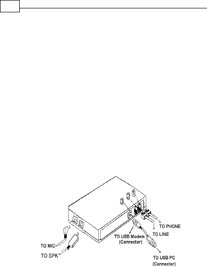
Hardware InstallationHardware Installation
Hardware InstallationHardware Installation
Hardware Installation
Phone : Telephone
Line : Telephone line jack
USB : USB Connector
MIC : Microphone jack
SPK : Speaker (for Stereo
only) jack
1. Plug the device terminal of the USB cable into
the connector marked on the back of the
modem .
2. Plug the other end of this cable into the USB
port on the back of your computer .
ƒ

4
Chapter 2
same line, plug one end of the optional
phone cable into the PHONE jack on
the modem; plug the other end into the
phone .Lift the telephone handset and
listen for a DIALTONE to check the connection.
3. Plug one end of the phone cable into the
modem’s LINE jack .Plug the other end
into the phone outlet .
4. To use telephone and the modem on the
•
‚
5
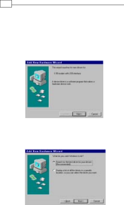
Chapter 2
2. Select the Search for the best driver for
your device (Recommended) option, then
click Next.
Installation Procedures forInstallation Procedures for
Installation Procedures forInstallation Procedures for
Installation Procedures for
Windows™ 98Windows™ 98
Windows™ 98Windows™ 98
Windows™ 98
1. When hardware installation complete,
Win 98 will auto detect your USB modem,
the following dialog box will appear,
click Next .
Chapter 2
6
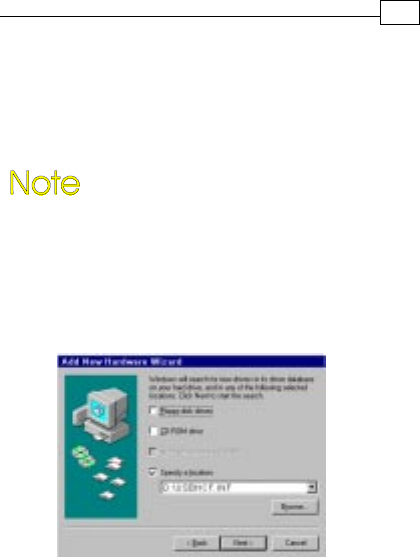
3. Place the CD containing driver for Win 98
into your CD ROM drive. Specify the
location of the modem driver, e.g.,
E:\USB_MODEM\CE_Country\WIN98\USB
MODEM.INF. Click Next.
CE_COUNTRYCE_COUNTRY
CE_COUNTRYCE_COUNTRY
CE_COUNTRY stands for all the
countries included in Pan-European
Approval, i.e., Austria, Belgium,
Denmark, Finland, France, Germany,
Greece, Iceland, Ireland, Italy,
Luxembourg, Norway, Portugal,
Spain, Switzerland, Holland, Sweden
and UK.
.
7
Chapter 2
Communication Software InstallationCommunication Software Installation
Communication Software InstallationCommunication Software Installation
Communication Software Installation
To install the communication software, ref er to
the manual contained on the provided CD.
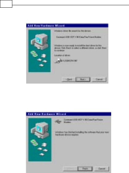
5. The installation has been completed. Click
Finish.
4. Windows will locate your driver. Click Next.

Chapter 3
CommandsCommands
CommandsCommands
Commands
Most people use the communication software
programs to tell modems what to do. Therefore,
you may not use the commands in this chapter.
However, if you prefer to communicate with your
modem directly, you can type the commands
described below.
This chapter describes how to work in the
terminal mode.
The CD bundled in your fax modem
package contains setails on AT
commands (file path:X:ROCKWELL\
PCIMODEM\AT_COMMAND.PDF).
TT
TT
Typing Commandsyping Commands
yping Commandsyping Commands
yping Commands
§ Use the BACKSPACE key to delete typing
errors.
§ Every command (except AA
AA
A/ and +++) must
begin with the AA
AA
ATT
TT
T or atat
atat
at prefix and be
entered by pressing the <Enter> key. For
example, to execute the VV
VV
V command, you
w ould type AA
AA
ATVTV
TVTV
T V and press the <Enter> key.
§ When you see an
nn
nn
n
, replace the
nn
nn
n
with one
of the letter or numeric options listed for that
command. For example, for the
EnEn
EnEn
En
command, you might type AA
AA
ATE1TE1
TE1TE1
TE1.
8

§ All defaults are based on the &F&F
&F&F
& F Hardware
Flow Control template load in NVRAMNVRAM
NVRAMNVRAM
NVRAM when
the modem is shipped.
AA
AA
AT CommandsT Commands
T CommandsT Commands
T Commands
A/A/
A/A/
A/ Re-executes the last issued command.
Used mainly to redial.
AA
AA
A Go off-hook and attempt to answer a
call.
AA
AA
ATS?TS?
TS?TS?
TS? Read Selected S-Register.Read Selected S-Register.
Read Selected S-Register.Read Selected S-Register.
Read Selected S-Register.
This command reads and displays the
selected S-Register. An S-Register can be
selected by using the AA
AA
ATSTS
TSTS
TS
n n
n n
n
command.
DD
DD
D
nn
nn
n
DialDial
DialDial
Dial
0-9 DTMF digits 0 to 9
P Pulse (rotary) dial
TTone dial
W Wait for second dial tone (X3 or
higher) ; linked to S6 register.
^Toggles calling tone ena ble/disa ble.
EE
EE
E
nn
nn
n
Command EchoCommand Echo
Command EchoCommand Echo
Command Echo
E0 Disable command echo
E1E1
E1E1
E1 Enable command echo
HH
HH
H
nn
nn
n
Disconnect (Hang-up)Disconnect (Hang-up)
Disconnect (Hang-up)Disconnect (Hang-up)
Disconnect (Hang-up)
H 0 Hang up (goes on-hook)
H 1 Go off-hook
II
II
I
nn
nn
n
IdentificationIdentification
IdentificationIdentification
Identification
9
Chapter 3

10
Chapter 3
I0 Report product code
I1 Report “OK”
I2 Report “OK” or “ERROR”
I3 Report firmware revision
I4 Report OEM defined identifier string
I6 Report modem data pump model and
internal code revision
MM
MM
M
nn
nn
n
Speaker ControlSpeaker Control
Speaker ControlSpeaker Control
Speaker Control
M 0 Speaker is always off
M1M1
M1M1
M 1 Speaker ON until CONNECT
M 2 Speaker is always on.
M 3 Speaker off during dialing and receiving
carrier and turn speaker on during
answering.
OO
OO
O
nn
nn
n
Return to On-Line Data ModeReturn to On-Line Data Mode
Return to On-Line Data ModeReturn to On-Line Data Mode
Return to On-Line Data Mode
O 0 Go on-line
O 1 Go on-line and retrain
PP
PP
PSet Pulse DialSet Pulse Dial
Set Pulse DialSet Pulse Dial
Set Pulse Dial
(for phone line that does not support
touch-tone dialing)
SS
SS
S
r=nr=n
r=nr=n
r=n
Set Register Set Register
Set Register Set Register
Set Register
rr
rr
r
to to
to to
to
nn
nn
n
SS
SS
S
nn
nn
n
??
??
?Display contents of S-Register Display contents of S-Register
Display contents of S-Register Display contents of S-Register
Display contents of S-Register
nn
nn
n
VV
VV
V
nn
nn
n
Result Code FormResult Code Form
Result Code FormResult Code Form
Result Code Form
V0 Numeric codes
V1V1
V1V1
V 1 Verbal codes
ZZ
ZZ
Z
nn
nn
n
Soft Reset and Restore ProfileSoft Reset and Restore Profile
Soft Reset and Restore ProfileSoft Reset and Restore Profile
Soft Reset and Restore Profile
Z0 Restore stored profile 0 after warm
reset.
Z1 Restore stored profile 1 after warm
reset.

&C&C
&C&C
&C
nn
nn
n
Control Carrier Detect (CD) SignalControl Carrier Detect (CD) Signal
Control Carrier Detect (CD) SignalControl Carrier Detect (CD) Signal
Control Carrier Detect (CD) Signal
&C0 CD override
&C1&C1
&C1&C1
& C 1 Normal CD operations
&D&D
&D&D
&D
nn
nn
n
DTR OptionDTR Option
DTR OptionDTR Option
DTR Option
& D 0 Ignore an on-to-off transition of DTR.
& D 1 Switch to on-line command mode
without disconnection.
&D2&D2
&D2&D2
& D 2 Normal DTR operations.
& D 3 Modem re-initialized. &Y determines
which profile is loaded.
&F&F
&F&F
&F
nn
nn
n
Load Factory ConfigurationLoad Factory Configuration
Load Factory ConfigurationLoad Factory Configuration
Load Factory Configuration
(Profile)(Profile)
(Profile)(Profile)
(Profile)
&F0 Restore factory configuration 0
&F1 Restore factory configuration 1
&W&W
&W&W
&W
nn
nn
n
Store Current ConfigurationStore Current Configuration
Store Current ConfigurationStore Current Configuration
Store Current Configuration
& W 0 Store the current configuration as
profile 0.
& W 1 Store the current configuration as
profile 1.
+MS+MS
+MS+MS
+MS Select ModulationSelect Modulation
Select ModulationSelect Modulation
Select Modulation
This command selects the modulation,
optionally enables or disables
automode, and optionally specifies the
lowest and highest connection rates
using one to four subparameters.
The format is:
AA
AA
AT+MS=<carrier>,<automode>,T+MS=<carrier>,<automode>,
T+MS=<carrier>,<automode>,T+MS=<carrier>,<automode>,
T+MS=<carrier>,<automode>,
<min_tx_rate>,<min_tx_rate>,
<min_tx_rate>,<min_tx_rate>,
<min_tx_rate>, <max_tx_rate>,<max_tx_rate>,
<max_tx_rate>,<max_tx_rate>,
<max_tx_rate>,
<min_rx_rate>,<max_rx_rate><min_rx_rate>,<max_rx_rate>
<min_rx_rate>,<max_rx_rate><min_rx_rate>,<max_rx_rate>
<min_rx_rate>,<max_rx_rate>
11
Chapter 3

CarrierCarrier
CarrierCarrier
Carrier Modula-Modula-
Modula-Modula-
Modula- Data RatesData Rates
Data RatesData Rates
Data Rates
tiontion
tiontion
tion (bps)(bps)
(bps)(bps)
(bps)
V21 V.21 300
V22 V.22 1200
V22B V.22bis 2400, 1200
V23C V.23 1200
V32 V.32 9600, 4800
V32B V.32bis 14400, 1200,
9600, 7200,
4800
V34 V.34 33600, 31200,
28800, 26400,
24000, 21600,
19200, 16800,
14400, 12000,
9600, 7200,
4800, 2400
V90V90
V90V90
V 9 0 V.90 56000, 54667,
53333, 52000,
50667, 49333,
48000, 46667,
45333, 42667,
41333, 40000,
38667, 37333,
36000, 34667,
33333, 32000,
30667, 29333,
28000
12
Chapter 3

13
Chapter 3
K56K56
K56K56
K56 K56 56000, 54000,
52000, 50000,
48000, 46000,
44000, 42000,
40000, 38000,
36000,34000,
32000
B103 Bell 103 30 0
B212 Bell 212 1200
<automode><automode>
<automode><automode>
<automode> Option SelectedOption Selected
Option SelectedOption Selected
Option Selected
0 Automode disabled
1 Automode enabled
For example:
AT+MS=K56,1,75,33600,75,56000
Where: K56 : select K56FLEX
1 : automode enabled
75 : min_rate data speed
300 bps
56000 : max_rate data speed
56000 bps
If you want to select V.34 28800 bps only,
please insure AT+MS=V34,0,75,28800,
75,28800.

14
Chapter 3
S-Register DefinitionsS-Register Definitions
S-Register DefinitionsS-Register Definitions
S-Register Definitions
S0S0
S0S0
S0 Number of Rings to Auto-AnswerNumber of Rings to Auto-Answer
Number of Rings to Auto-AnswerNumber of Rings to Auto-Answer
Number of Rings to Auto-Answer
The number of rings the modem waits
for before it auto answers.
Range: 0-255 (rings)
Default: 0
S6S6
S6S6
S6 Wait Time before Blind DialingWait Time before Blind Dialing
Wait Time before Blind DialingWait Time before Blind Dialing
Wait Time before Blind Dialing
The time to pause after off-hook before
blind dialing.
Range: 2-255 (U.S.)
Default: 2 (Country dependent)
S7S7
S7S7
S7 Waiting Time before Carrier DetectWaiting Time before Carrier Detect
Waiting Time before Carrier DetectWaiting Time before Carrier Detect
Waiting Time before Carrier Detect
The time to wait for a carrier from the
remote modem before hanging up.
Range: 1-255
Default: 50 (seconds)
S8S8
S8S8
S8 Pause Time For Dial DelayPause Time For Dial Delay
Pause Time For Dial DelayPause Time For Dial Delay
Pause Time For Dial Delay
The time to pause for the pause dial
modifier, “Comma”.
Range: 0-255
Default: 2 (seconds)
S9S9
S9S9
S9 Carrier Detect Response TimeCarrier Detect Response Time
Carrier Detect Response TimeCarrier Detect Response Time
Carrier Detect Response Time
The time a signal is detected an
qualified as a carrier. This timing lets
your modem ignore spurious signals
that are the same frequency as the
carrier. Higher S9 values reduce the
chance of a carrier being detected.

Range: 1-255
Default: 6 (0.6 second)
S10S10
S10S10
S10 Lost Carrier Lost Carrier
Lost Carrier Lost Carrier
Lost Carrier TT
TT
To Hang Up Delao Hang Up Dela
o Hang Up Delao Hang Up Dela
o Hang Up Delayy
yy
y
The time the modem waits before
hanging up for carrier loss.
Range: 1-255
Default: 14 (1.4 seconds)
S11S11
S11S11
S11 DTMF DTMF
DTMF DTMF
DTMF TT
TT
Tone Durationone Duration
one Durationone Duration
one Duration
The time for DTMF tone dialing and
the time between the tone spacing.
Range: 50-255
Default: 95 (0.95 second, country
dependent)
15
Chapter 3