Q MAC Electronics HF90 HF-90 User Manual Acrobat Distiller Job 8
Q-MAC Electronics Pty Ltd HF-90 Acrobat Distiller Job 8
Contents
- 1. User guide
- 2. Technical manual
- 3. Technical Manual
- 4. User Guide
User Guide
HF-90 Operation & Installation Guide

HF-90 Operation & Installation Guide
No part of this manual may be copied, transcribed, translated
or reproduced in any manner or form whatsoever, for
commercial purposes, without obtaining prior written
permission from Q-MAC Electronics Pty Ltd. However,
limited copying is permitted for private use providing
authorship is acknowledged.
© Copyright of Q-MAC Electronics Pty Ltd.
Print date: Feb 2004
Literature Reference Number: GUIDE07.PUB

HF-90 Operation & Installation Guide
TABLE OF CONTENTS
TABLE OF CONTENTSTABLE OF CONTENTS
TABLE OF CONTENTS
Introduction
1.1 About this Guide ..................................................... 1
1.2 Safe working distances ............................................ 2
1.2 Glossary of terms ..................................................... 2
Understanding HF/SSB
2.1 What is HF/SSB? ..................................................... 3
2.2 How does HF/SSB work? ........................................ 4
2.3 Factors which affect HF/SSB communications ....... 7
Speaking on air
3.1 How to make a voice call ........................................ 9
3.2 Radio alphabet ....................................................... 11
Overview of the HF-90
4.1 HF-90 Versions and Models .................................. 12
4.2 Operating the HF-90 .............................................. 14
Standard functions
5.1 ON/OFF switch ..................................................... 16
5.2 Volume control knob ............................................. 18
5.3 Channel up/down scroll keys ................................. 19
5.4 Clarifier up/down scroll keys ................................ 21
5.5 USB/LSB mode selection key ............................... 23
5.6 Tune key ................................................................ 25
5.7 LED display ........................................................... 26
5.8 Erase function ........................................................ 27
5.9 Press to talk (PTT) switch ....................................... 28
Section 1
Section 2
Section 3
Section 4
Section 5

HF-90 Operation & Installation Guide
Advanced functions
6.1 Selcall .................................................................... 29
6.2 Telcall .................................................................... 33
6.3 Beacon ................................................................... 38
6.4 Selcall Scan ........................................................... 40
6.5 Selcall Mute .......................................................... 41
6.6 Advanced functions summary ............................... 42
Compatible products
7.1 TA-90 autotune system ......................................... 44
Installation
8.1 Mobile systems ...................................................... 45
8.2 Vehicle systems ..................................................... 48
8.3 Base station systems .............................................. 51
External connectors .............................................. 54
Accessories ........................................................... 55
Further reading ...................................................... 56
Notes ....................................................................... 57
Section 6
Section 7
Section 8
Section 9
Section 10
Section 11
Addendum
Notes

HF-90 Operation & Installation Guide
1
1. INTRODUCTION
1. INTRODUCTION1. INTRODUCTION
1. INTRODUCTION
About this Guide
The main purpose of this guide is to provide you, the HF-90
user, with all the information you require to ensure optimum
performance from your HF-90 radio.
The Guide explains in detail how to operate the HF-90 once it
has been programmed by an authorised Q-MAC
Representative. It also contains an Addendum concerning
Field Programming, which is relevant only to international
users (outside of Australia) who are licensed to program their
own operating frequencies.
The Guide also covers basic principals of installation by way
of check-lists. It does not give comprehensive instructions on
how to install the HF-90. We recommend that the installation
of your HF-90 be carried out by a qualified Q-MAC
Representative.
This device complies with Part 90 of the FCC Rules.
Operation is subject to the condition that this device does not
cause harmful interference.
Section 1.1
HF-90 Operation & Installation Guide
Section 1.2
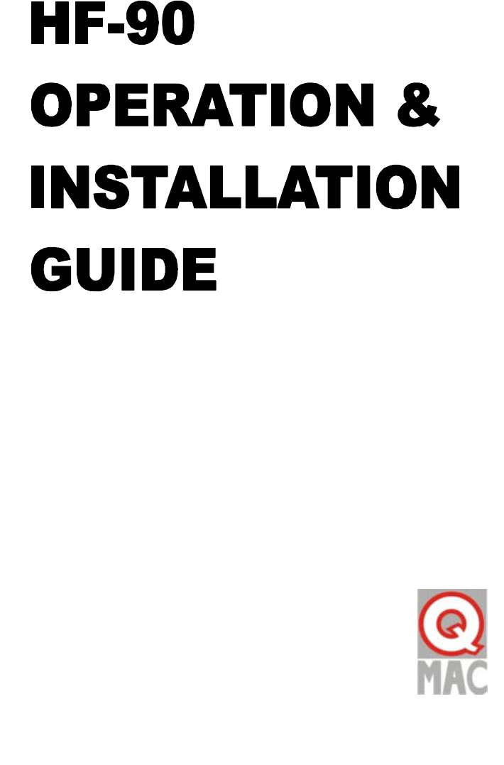
Safe Working Distances for Q-MAC Antennas
1. HF-90 used with QM7005 Portable End-Fed Broadband Antenna
Safe working distance 0.2m (20cm)
Do not touch antenna wire
No RF burn risk
WARNING LABEL
2. HF-90 used with QM7001 Broadband Dipole Antenna
Safe working distance 0.2m (20cm)
Do not touch antenna wire
No RF burn risk
WARNING LABEL
2
HF-90 Operation & Installation Guide
Section 1.2
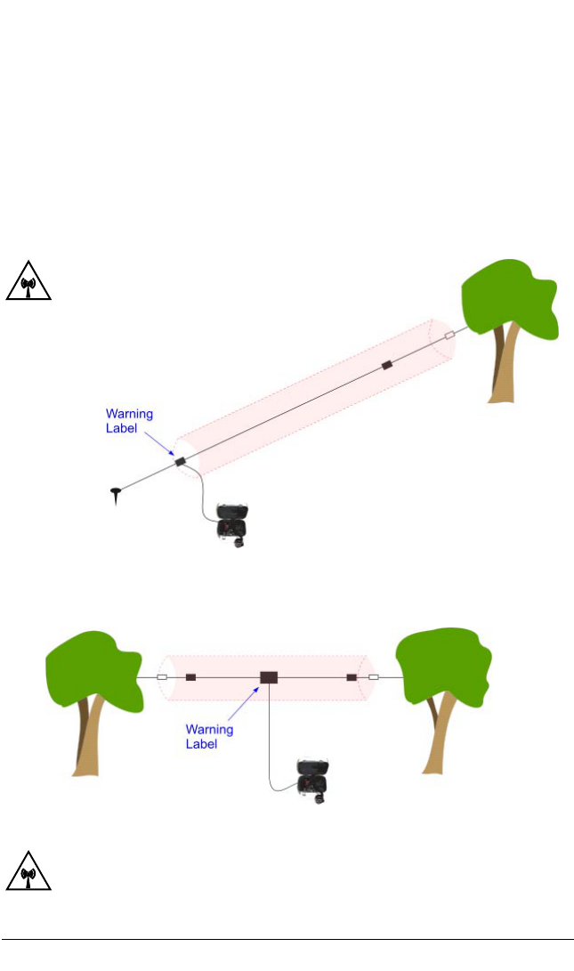
3. HF-90 used with ML-90 Vehicle Loop Antenna
4. HF-90 used with TA-90 Vehicle Tuner and QM7131 or
QM7133 continuously loaded whip antenna.
Safe working distance 1.0m (100cm)
Do not touch antenna arm during transmission
RF burn risk
WARNING LABEL
Safe working distance 1.0m (100cm)
Do not touch whip or spring during
transmission
RF burn risk
WARNING LABEL
3
HF-90 Operation & Installation Guide
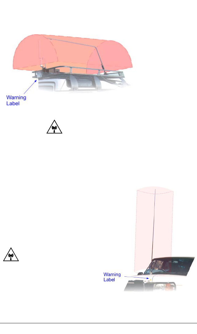
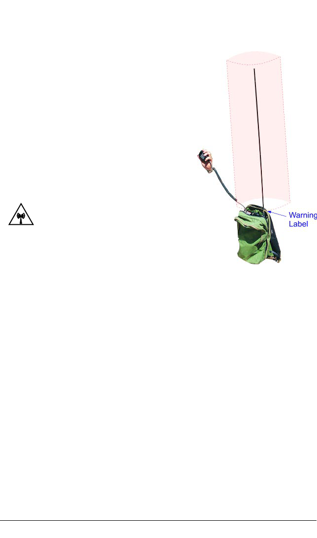
5. HF-90 used with TA-99 or TM-90 whip tuner and
QM7301 3m 6-section whip or
QM7303 3m 8-section whip or
QM7302 1m 2-section whip or
QM7304 1m 4-section whip or
QM7309 1m tape whip
Safe working distance 0.6m (60cm)
Do not touch antenna during transmission
RF burn risk
WARNING LABEL
Section 1.2
4

HF-90 Operation & Installation Guide
Glossary of terms
ATU Antenna Tuning Unit
BITE Built In Test Equipment
CB Citizen Band
DTMF Dual Tone Multi Frequency (touch-pad)
HF High Frequency
Hz Hertz (measure of frequency)
ID Identification
kHz Kilohertz (measure of frequency)
LSB Lower Sideband
MHz Megahertz (measure of frequency)
PSU Power Supply Unit
PTT Press To Talk
RFDS Royal Flying Doctor Service
Selcall Selective Call
SSB Single Sideband
Telcall Selective Call with Telephone Call facility
USB Upper Sideband
5
Section 1.3

HF-90 Operation & Installation Guide
2. UNDERSTANDING HF/
2. UNDERSTANDING HF/2. UNDERSTANDING HF/
2. UNDERSTANDING HF/SSB
SSBSSB
SSB
What is HF/SSB?
HF (High Frequency) is the section of the radio spectrum
between 1.6 and 30 MHz. SSB (Single Sideband) is a form of
radio modulation. HF/SSB combines the characteristics of
HF frequencies with SSB modulation to provide very
efficient, flexible and inexpensive communications.
HF/SSB will enable short, medium and long range
communications over flat, hilly or mountainous terrain -
without the need for expensive re-transmission devices, such
as the repeaters used in VHF (Very High Frequency)
communications. Also, unlike satellite communications,
there is no dependence on a service provider with all the
associated ongoing costs.
In many remote areas around the globe, and in certain
conditions, HF/SSB is the only form of communication
possible.
6
Section 2.1

HF-90 Operation & Installation Guide
How does HF/SSB work?
When HF/SSB radio waves are generated there are usually
two components:-
The ground-wave, which travels directly from the
transmitting antenna to the receiving antenna
following the contours of the earth, and ...
The sky-wave, which travels upward and at an angle
from the transmitting antenna, until it reaches the
ionosphere (an ionised layer high above the earth’s
surface) and is refracted back down to earth, to the
receiving antenna.
Generally speaking, ground-wave is used to communicate
over shorter distances (in most cases less than 50km).
However, because ground-wave follows the contours of the
earth, it is affected by the type of terrain it passes over. For
example, ground-wave is rapidly attenuated (reduced) when it
passes over hilly or mountainous terrain.
Sky-wave is used to communicate over medium range and
longer distances (up to 3,000km and beyond in good
conditions). Because of the nature of sky-wave propagation,
it is not affected by the type of terrain it passes over. This
means that communications can be achieved over medium
and long distances in mountainous areas, using HF/SSB sky-
wave. However, sky-wave propagation is affected
significantly by other factors as outlined in Section 2.3 of this
Guide.
Ground-wave and sky-wave examples are illustrated on the
following page.
7
Section 2.2
HF-90 Operation & Installation Guide
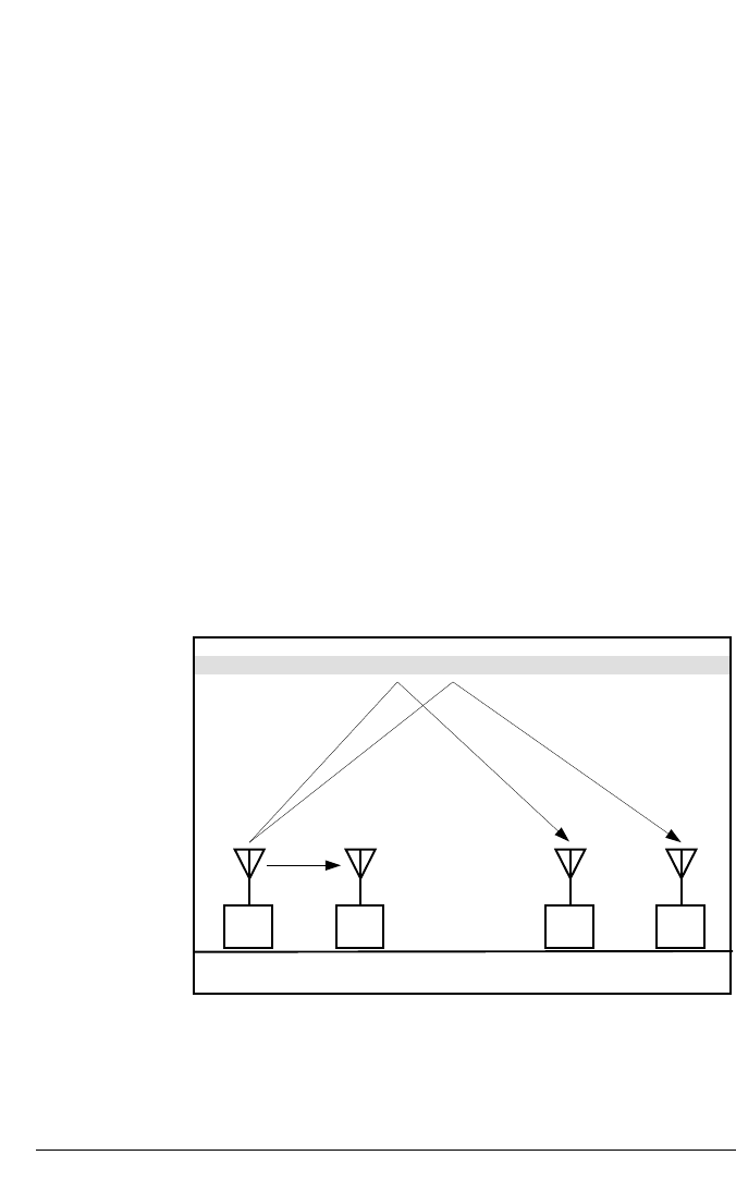
A
Not to scale
20 km 2,000 km 800 km
D C B
The following illustrations show the characteristics of
ground-wave and sky-wave propagation during the day time
and night time. Each illustration clearly shows the level of
the ionosphere.
In both illustrations Station A communicates with Stations B,
C and D. Propagation from Station A to B is via ground-
wave. You will notice how the time of day, and level of the
ionosphere, does not affect ground-wave.
Propagation from Station A to C and D is via sky-wave. You
will notice how the time of day, and level of the ionosphere,
affects sky-wave.
Under each diagram there are recommended working
frequencies listed. Please note that these will vary according
to time of year and other factors. They are intended only as a
guide and are subject to change.
8
Section 2.2
Ionosphere
A to B - Recommended working frequency is 3 MHz
A to C - Recommended working frequency is 7 - 9 MHz
A to D - Recommended working frequency is 13 - 16 MHz
DAY TIME:
Sun is higher
Ionosphere is
higher
Optimum working
frequency is
higher
Radio propagation illustrated
HF-90 Operation & Installation Guide
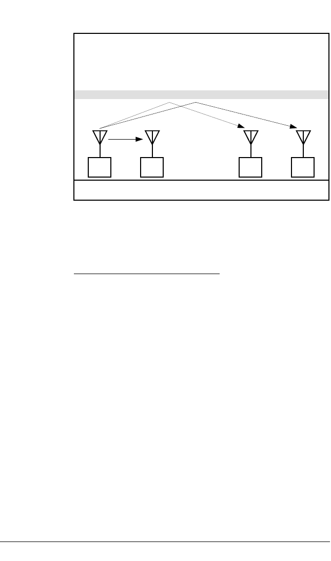
Not to scale
D
C B
A
2,000 km 800 km 20 km
Ionosphere
A to B - Recommended working frequency is 3 MHz
A to C - Recommended working frequency is 5 to 7 MHz
A to D - Recommended working frequency is 9 to 12 MHz
NIGHT TIME:
Sun is lower
Ionosphere is
lower
Optimum working
frequency is lower
9
Section 2.2

HF-90 Operation & Installation Guide
Factors which affect HF/SSB communications
10
Section 2.3
As a rule, the higher the sun is, the smaller the distance
covered - for a particular frequency. This means that you can
use a low frequency to communicate during times when the
sun is low in the sky (early morning, late afternoon and
evening), but you will need to use a higher frequency to cover
the same distance during times when the sun is high in the sky
(midday). You will need to observe the above rule carefully if
your radio has a limited number of frequencies programmed
into it, as you may only be able to communicate effectively at
certain times of the day.
There are a number of different factors which will affect the
success of your communications via HF/SSB radio. These
are outlined below:-
Your choice of frequency
Generally speaking the higher the frequency you select, the
longer the distance covered. Frequency selection is perhaps
the most important factor which will impact on the success of
your HF/SSB communications.
Correct frequency selection is made easier with the use of a
Beacon facility (refer to Section 6.3 of this Guide for details
on the HF-90 Beacon).
Time of day
Season
The above rule (the higher the sun is, the smaller the distance
covered - for a particular frequency) also applies to the
season, or month of the year. Generally speaking, you will
need to use a higher frequency to communicate effectively
during Summer months, than you would need to in Winter.

HF-90 Operation & Installation Guide
The equipment you choose and the way in which it is set up
will also affect the success of your HF/SSB communications.
With respect to system configuration, your choice of antenna
system and power supply is critical. What is good for one
system is not necessarily good for another. The way in which
your system is installed is also extremely important. Certain
rules which must be observed for HF/SSB installations, such
as correct antenna positioning and proper grounding, will
affect the success of your communications, sometimes quite
dramatically. Installation is covered in more detail in Section
8 of this Guide.
To ensure no mistakes are made with your system
configuration and/or installation, you should speak to your Q-
MAC Representative.
Please note that communications on any HF/SSB radio will sound
different to that on a VHF (Very High Frequency) radio, UHF (Ultra
High Frequency) radio or telephone. Because of the nature of HF/
SSB propagation, a marginal level of background noise is always
expected. This is normal.
11
Section 2.3
Weather conditions
Certain weather conditions will also affect the success of your
HF/SSB communications. You may find that in stormy
conditions the background noise on your radio will increase,
as a result of ‘static’ caused by lightning.
Man-made electrical interference
Interference of an electrical nature can be caused by
overhanging power lines, high power generators, air-
conditioners, thermostats, refrigerators and vehicle engines,
when in close proximity to your antenna. The result of such
interference may be a continuous or intermittent increase in
the level of background noise.
System configuration and installation
Special Note:

HF-90 Operation & Installation Guide
3. SPEAKING ON AIR
3. SPEAKING ON AIR3. SPEAKING ON AIR
3. SPEAKING ON AIR
How to make a voice call
Here follow a number of rules you should observe when
making a voice call on your HF-90 radio (or any HF/SSB
radio):-
Select the appropriate channel (according to its
frequency).
Before voice calling the other station, listen to the
channel to see if it is busy. If the channel is busy you
should wait until communications have ceased. If the
channel is free you can proceed with your call.
Press and hold down the PTT switch on your
microphone/handset and give a long voice call (5-10
seconds), indicating the station you are calling on.
“Perth base, Perth base, Perth base, this is Mobile 5ABC, Mobile
5ABC, Mobile 5ABC, calling on Channel 50 - Over”.
Please note this is also the recommended method of
voice calling any Telstra Radphone Station or RFDS
(Royal Flying Doctor Service) Station
(relevant only to
users within Australia).
It is better if you can end all of your communications
with the word “OVER”. This indicates clearly to the
other user that you have finished what you wish to say,
so that they may speak. This is very important,
particularly when you are speaking to someone who is
on a telephone (via a telephone interconnect unit).
Example:
12
Section 3.1

HF-90 Operation & Installation Guide
Ensure that your mouth is always close to the
microphone (or mouthpiece on a telephone handset)
when speaking over HF/SSB radio.
As a general rule, you should speak clearly and a little
slower and louder than normal, when speaking over HF/
SSB radio.
Instructions for making a Selcall (Selective Call) are outlined
in Section 6.1 of this Guide.
13
Section 3.1

HF-90 Operation & Installation Guide
Radio alphabet
When it is necessary to spell out words over the radio, you
should use the following words to denote individual letters.
The Radio Alphabet, listed below, is used in all countries as
an International Standard.
Letter Word Letter Word
A
Alpha
N
November
B
Bravo
O
Oscar
C
Charlie
P
Papa
D
Delta
Q
Quebec
E
Echo
R
Romeo
F
Foxtrot
S
Sierra
G
Golf
T
Tango
H
Hotel
U
Uniform
I
India
V
Victor
J
Juliet
W
Whisky
K
Kilo
X
X-ray
L
Lima
Y
Yankee
M
Mike
Z
Zulu
14
Section 3.2

HF-90 Operation & Installation Guide
4. OVERVIEW OF THE H
4. OVERVIEW OF THE H4. OVERVIEW OF THE H
4. OVERVIEW OF THE HF
FF
F-
--
-90
9090
90
HF-90 Models
the HF-90 is available in two different formats. Namely:-
The Standard Model, and ...
The Advanced Model.
Section 4.1
15
If you require basic functions, the Standard Model HF-90 is
quite suitable. However, if you require advanced functions
such as Selcall related facilities, then you will need the
Advanced Model HF-90. This is an additional option.
If you have a Standard Model HF-90, you can have this
upgraded to an Advanced Model easily and cost effectively.
The upgrade comprises of new operating software and a
DTMF (Dual Tone Multi Frequency) microphone or handset.
Simply enquire with your Q-MAC Representative.
Section 6 of this Guide covers functions which are available
only on the Advanced Model HF-90. All other Sections of
this Guide are relevant to both Models.
HF-90 Operation & Installation Guide
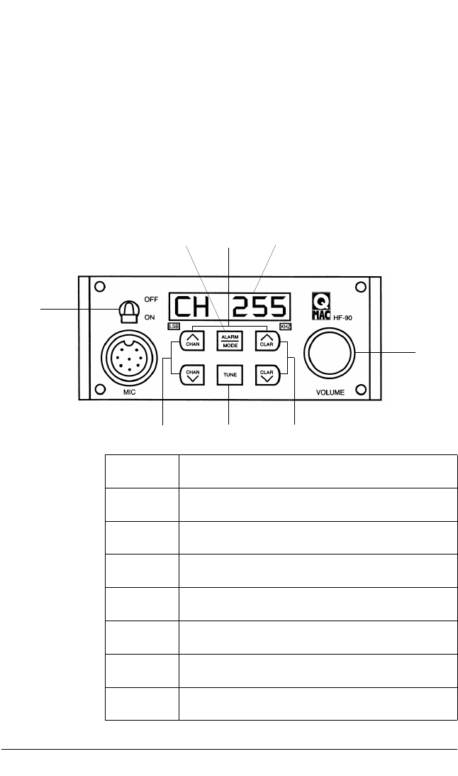
Operating the HF-90
The following illustration shows the operating controls which
are on the front panel of the HF-90 radio. The next Section of
this Guide (Section 5) gives detailed instruction on how to use
each of these controls.
Section 4.2
Front panel controls
16
ON/OFF switch
Volume control knob
Channel up/down scroll keys
Clarifier up/down scroll keys
Alarm key & USB/LSB mode selection key
Tune key
LED display
Erase function
HF-90 Operation & Installation Guide
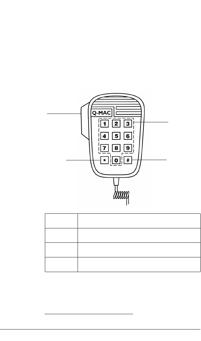
The following illustration shows the operating controls which
are on the DTMF microphone/handset, supplied with the
Advanced Model HF-90. Section 6 of this Guide gives
detailed instruction on how to use each of these controls.
Section 4.2
DTMF microphone/handset controls
17
Press to talk (PTT) switch
STAR key
Numeric keys
HASH key
HF-90 Operation & Installation Guide
5. STANDARD FUNCTION
5. STANDARD FUNCTION5. STANDARD FUNCTION
5. STANDARD FUNCTIONS
SS
S
ON/OFF switch
To switch the HF-90 on, move the ON/OFF switch downward
to the ON position. When the set is switched on an audible
beep is heard and the front panel display appears as follows:-
18
Section 5.1
Switching the HF-90 on

HF-90 Operation & Installation Guide
The display on the previous page will be shown for half a
second, immediately followed by another display showing
relevant software information. For example:-
This display shows: Option Level 1 - Release 1,
Version 05.
19
Section 5.1
The display showing software information will also time-out
after half a second. If you have an Advanced Model HF-90,
the display will then show your Selcall ID (4 digits) for one
second. At this point the HF-90 will revert to the default
channel/frequency display (refer to Section 5.8 of this Guide).
The channel/frequency shown will be the one which was last
in use.
Switching the HF-90 off
To switch the HF-90 off, move the ON/OFF switch upward to
the OFF position.

HF-90 Operation & Installation Guide
Volume control knob
To increase the volume (of received signal) on the HF-90
rotate the VOLUME control knob in a clockwise direction.
Or, to decrease the volume on the HF-90 rotate the VOLUME
control knob in an anti-clockwise direction.
The VOLUME control knob on the HF-90 uses an
Incremental Shaft Encoder. This means that there are no
physical high/low limits when adjusting the volume - ie. the
knob will keep rotating without coming to a stop. As you
rotate the knob you will detect the high/low limits. Once a
limit is reached, turning the knob in the same direction will no
longer affect the volume. A small audible click occurs with
each increase and decrease of volume.
Please note that the VOLUME control knob can also be used as a
Selcall Mute control on the HF-90 Advanced Model. Please refer
to Section 6.5 of this Guide.
Special Note:
Advanced Model
20
Section 5.2
Adjusting volume

HF-90 Operation & Installation Guide
Channel up/down scroll keys
To select a channel higher than the one in use press the
CHAN (up) key. By pressing and releasing the CHAN (up)
key you will proceed to the next (higher) programmed
channel. By pressing and holding down the CHAN (up) key
you can scroll upward through a number of channels rapidly.
When the desired channel number is reached you simply
release the CHAN (up) key and the display will stop on the
new channel number. For example:-
21
Section 5.3
Selecting a channel
To select a channel lower than the one in use, press the
CHAN (down) key in the same manner as mentioned above
for the CHAN (up) key.
This display shows that the selected channel is
Channel 200.
If you are operating an International Version HF-90, the
channel display will time out after two seconds, after which
time the operating frequency (receive frequency) will appear.
For example:-
This display shows a channel frequency of
12650.0kHz (which is the same as 12.65MHz).

HF-90 Operation & Installation Guide
22
Section 5.3
When scrolling up and down channels you may notice that
your channel numbers do not follow a regular sequence such
as 1, 2, 3, 4, 5. For example, they could appear as 1, 2, 13,
56, 245. This will depend on how your HF-90 has been
programmed and for what use.
The maximum number of channels you can have programmed
into the HF-90 is 255. Please note that when scrolling, the
channel numbers will ‘wrap around’ from highest to lowest
and vice versa. For example, the channels on your HF-90
could appear in a sequence such as this;
253, 254, 255, 1, 2, 3.
If you have an Advanced Model HF-90 you may notice, when
scrolling between the lowest and highest channel number, that the
display shows the word “SCAN”. This is a separate channel
designated for Selcall Scan (refer to Section 6.4 of this Guide).
Special Note:
Advanced Model
Channel configuration
Once the appropriate channel has been selected, you are ready
to commence communication. To transmit, simply press and
hold down the PTT switch on your microphone/handset (refer
to Section 3.1 of this Guide).
Please note that, if you are using the HF-90 in conjunction with a
Q-MAC Electronics autotune system, you will hear a continuous
high pitched tone for a few seconds, once you have pressed the
PTT switch for the first time on a new channel. This is the Tuner
entering its tune sequence (refer to Section 7.1 of this Guide).
Special Note:
Using an autotune
system
HF-90 Operation & Installation Guide
Clarifier up/down scroll keys
The clarifier function allows you to adjust the quality of audio
(to obtain maximum intelligibility) by fine tuning the pitch of
the received signal. A clarifier adjustment may be required
when receiving a signal which is slightly off-frequency.
Clarifier does not work while the set is in transmit mode and
will not affect the transmit frequency.
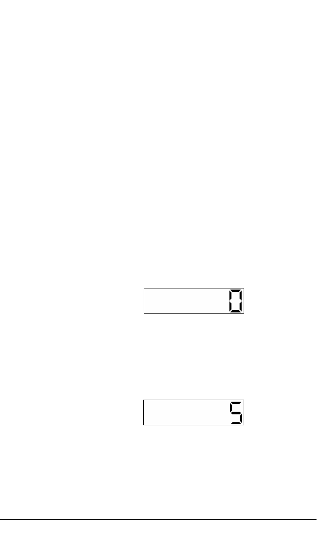
The zero in the above display indicates that the
clarifier has not yet been adjusted - ie. it is at
zero level.
Press and release the CLAR (up) key again. This time the
display will appear as follows:-
This display shows that the clarifier has been
adjusted by +5 units.
Section 5.4
Adjusting clarifier
The CLAR keys on the HF-90 will adjust the clarifier by
increments of 5 units. The clarifier function enables a
maximum adjustment of ±100 units.
To adjust the clarifier level on your HF-90 in an upward
direction (thus increasing the receive frequency), press and
release the CLAR (up) key. The first time you press the
CLAR (up) key, the display will appear as follows:-
23

HF-90 Operation & Installation Guide
Each subsequent press of the CLAR (up) key will increase the
receive frequency by another 5 units, until the upper limit of
100 units is reached.
To adjust the clarifier level on your HF-90 in a downward
direction (thus decreasing the receive frequency), press and
release the CLAR (down) key. The first time you press the
CLAR (down) key the display will show the numeral zero (as
illustrated on the previous page). Press and release the CLAR
(down) key again. This time the display will appear as
follows:-
This display shows that the clarifier has been
adjusted by -5 units.
Each subsequent press of the CLAR (down) key will decrease
the receive frequency by another 5 units, until the lower limit
of -100 units is reached.
Once the clarifier has been adjusted for a particular channel
the new setting will remain in place until another channel is
selected or until the HF-90 is switched off. When returning
back to the original channel the clarifier setting is not saved -
ie. it will be set back at the zero level.
Section 5.4
24

HF-90 Operation & Installation Guide
USB/LSB mode selection key
The HF-90 will operate in either USB (Upper Sideband) or
LSB (Lower Sideband) mode.
This display shows that the channel in use
(Channel 245) is set to LSB mode. Note the
LSB label below the display window.
To change the operating mode for a particular channel, first
select the appropriate channel (refer to Section 5.3 of this
Guide), then press and release the MODE key. The new
mode will now be selected and the display will show this
change. For example:-
This display shows that USB mode is selected.
OR ...
LSB
Section 5.6
LSB decimal indicator
If LSB channels are pre-programmed in the HF-90 or
manually selected, a decimal indicator will appear on the
bottom left of the display. The decimal indicator appears just
above the LSB label (which is printed below the display
window). For example, if Channel 245 is selected and it is set
to LSB mode, the display appears as follows:-
Changing the operating mode
25

HF-90 Operation & Installation Guide
This display shows that LSB mode is selected.
Subsequent presses of the MODE key will simply allow you
to move back and forth between USB and LSB modes.
Once the operating mode has been changed for a particular
channel, this setting will remain in place until another channel
is selected or until the HF-90 is switched off. When returning
back to the original channel, the operating mode is not saved -
ie. it will go back to its original programmed setting.
This display shows that the mode selection
function is “CLOSED” - ie. disabled.
When you see the above message on the display you will
know that the operating mode cannot be manually adjusted.
Some countries have restrictions regarding the operating mode(s)
which can be used on an HF radio.
Warning:
Section 5.6
When mode selection has been disabled ...
Please note that if manual mode selection has been disabled
on your set you will not be able to alter the pre-programmed
mode settings. In this instance, when you press and release
the MODE key, your display will show the word “CLOSED”.
It will appear as follows:-
26

HF-90 Operation & Installation Guide
Tune key
The tune function allows you to transmit a continuous carrier
signal at reduced power for manually tuning long wire
antennas and un-tuned whips, when used in conjunction with
an antenna tuning unit (ATU).
This display shows that the tune function is in
process.
Section 5.7
Activating the tune function
To activate the tune function press and release the TUNE key.
Your HF-90 will transmit a continuous carrier signal at
reduced power for several seconds. You will hear a
continuous tone and the display will appear as follows:-
27

HF-90 Operation & Installation Guide
The default display on your HF-90 will appear as follows:-
It will show the frequency last in use
.
This default
display is always preceded by the channel last in use
(which times out after approximately two seconds).
Your HF-90 radio will always revert to a default display in
the following circumstances:-
When it is first switched on.
When you have cancelled a function, or ...
When a function has automatically timed out.
Default display
The HF-90 incorporates an automatic display time-out
facility, which applies to the use of most advanced functions
within the set (such as sending Selcalls, Telcalls or Beacon
Requests).
The time-out facility will take effect once you have pressed a
function key from the DTMF keypad on your microphone/
handset. Once the function is completed, or if another key is
not pressed, the new display will automatically time-out after
a period of five seconds. At this point the HF-90 will revert
to the default display.
Automatic display time-out
LED display
28
Section 5.8
HF-90 Operation & Installation Guide
The HF-90 incorporates a direct entry Erase Function which
allows the operator to quickly and easily erase the memory of
the HF-90. This feature may be required if you wish to
ensure that channel/frequency information remains secure
.
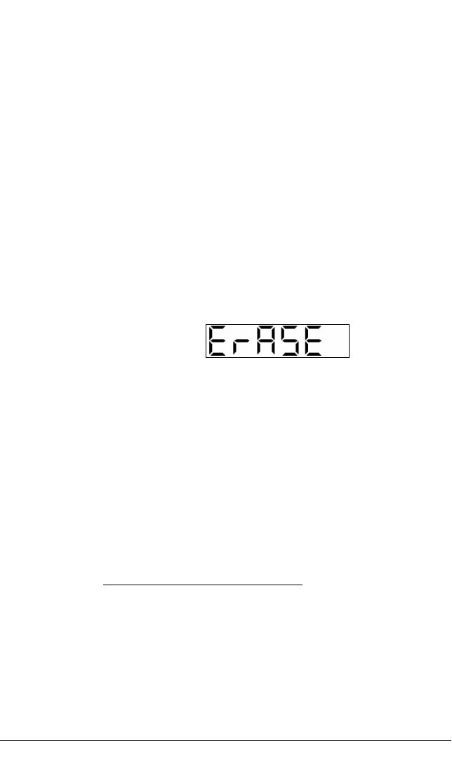
To erase the memory of the HF-90, simply hold down the
CHAN (up) and CLAR (up) keys together for six seconds.
The display will appear as follows:-
Erase function
This display shows that the Erase Function is in
progress.
The display will show the word “ErASE” for twelve seconds
whilst the memory is being erased. Finally the HF-90 will
reset as though being turned on for the first time (refer to
Section 5.1 of this Guide).
Please note that this function will erase all channels in memory
except for one - the lowest channel. This is because the HF-90
requires a minimum of one channel programmed in memory at all
times.
Special Note:
29
Section 5.9

HF-90 Operation & Installation Guide
To cancel any function, simply press and release the PTT
switch on your microphone/handset. This will immediately
cancel the function and the current display. The HF-90 will
then revert back to the default display.
This display shows a transmit frequency of
12650.0kHz (which is the same as 12.65MHz).
Viewing the transmit frequency
To view the transmit frequency, simply press the PTT switch
on your microphone or handset. The display will show the
frequency in kHz. Because the channel resolution of the HF-
90 is 100Hz, the frequency is displayed to one decimal place.
For example:-
Press to talk (PTT) switch
To begin communications (ie. to transmit), simply press and
hold down the PTT switch on your microphone/handset and
then communicate in accordance with radio protocol (refer to
Section 3 of this Guide).
Please note that, if you are using the HF-90 in conjunction with a
Q-MAC Electronics autotune system, you will hear a continuous
high pitched tone for a few seconds, once you have presses the
PTT switch for the first time on a new channel. This is the Tuner
entering its tune sequence (refer to Section 7.1 of this Guide).
Special Note:
Using the autotune
system
To begin communications
Cancelling a function
30
Section 5.10

HF-90 Operation & Installation Guide
6. ADVANCED FUNCTION
6. ADVANCED FUNCTION6. ADVANCED FUNCTION
6. ADVANCED FUNCTIONS
SS
S
Selcall
Selcall (short for Selective Call) allows you to make and
receive calls to/from another radio easily and directly, by a
simple method of digital signalling. Selcall allows you to
send a coded alarm signal to alert a specific radio user that
they are being called. If the Selcall is received successfully
by the other radio user, their set will automatically transmit a
positive confirmation alarm back to your set.
For you to be able to use Selcall, the radio which you wish to
communicate with must also have the Selcall function. The
HF-90 uses a Selcall format which is compatible with all
major Australian brands and Telstra Radphone Services.
Please refer to the end of Section 6.1 for instructions on how
to program the Selcall ID number.
To send a Selcall
use the DTMF
keypad on your
mic./handset
(or front panel - if
using HF-90 with
avionics interface).
This display shows that Selcall has been
initiated.
Sending a Selcall
Prior to sending a Selcall, ensure you are on the correct
Selcall channel. We recommend using the Beacon facility to
select the appropriate Selcall channel (refer to Section 6.3 of
this Guide).
First press the STAR (*) key. Pressing this key initiates the
Selcall procedure. Your display will appear as follows:-
31
Section 6.1

HF-90 Operation & Installation Guide
Next, press the numeric keys to select the appropriate Selcall
ID (four digits) of the station you wish to contact. As you
press each individual numeric key, the corresponding number
will appear on the display until all numbers have been
selected. At this point all numbers will appear on the display
together. For example:-
This display shows that Selcall ID 1234 has
been selected.
If in the process of selecting the Selcall ID you press an
incorrect number, you can clear the display by pressing and
releasing the PTT switch on the microphone.
Once the Selcall ID has been correctly selected, press the
STAR key again to send the Selcall. You will hear a varying
high pitched tone as the Selcall is being transmitted, and your
display will appear as follows:-
This display shows that Selcall is being sent - ie.
in transmit mode.
Several seconds after pressing the STAR key to send the
Selcall, you should hear a series of high pitched beeps. This
is your positive confirmation (known as the Selcall
Confirmation) being transmitted from the called station to let
you know that your Selcall has been received successfully. If
you do not hear the Selcall Confirmation you should repeat
the procedure outlined above, on the same channel or a new
channel. If your Selcall is not successful this may be due to
inappropriate frequency selection or excessive interference
(refer to Section 2.3 of this Guide). In the event of strong
interference, it may be necessary to repeat Selcall up to three
times.
32
Section 6.1
HF-90 Operation & Installation Guide
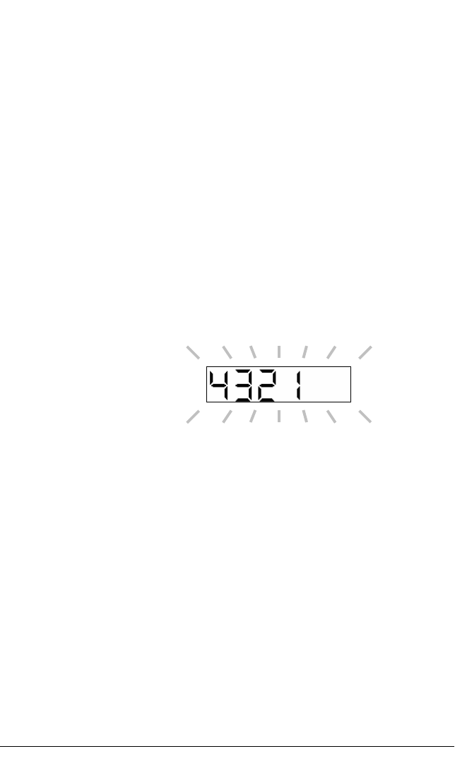
Your display will revert to the default channel display as soon
as a Selcall confirmation is received, or if the call is
unsuccessful.
This flashing display shows that you have
received a call from Station No. 4321.
You can respond to the call immediately by pressing your
microphone PTT switch and commencing communications
with the calling station. Pressing the PTT switch immediately
cancels the Selcall Alarm. Once the Selcall Alarm has been
cancelled, the display will revert to the default channel
display.
When a Selcall is being received you should not adjust the
user controls, as this may result in the incoming call being
lost.
Receiving a Selcall
When receiving a Selcall you will hear a series of continuous
loud beeps (which cannot be adjusted with the VOLUME
control knob) - this is the Selcall Alarm. In addition your
display will flash the Selcall ID of the station that is calling
you. For example:-
Selcall Resend
Please note that you can resend the last recorded Selcall
quickly and easily, by pressing the STAR key twice.
33
Section 6.1

HF-90 Operation & Installation Guide
If the Selcall Alarm is not cancelled the audible alarm will
time-out after sixty seconds. However, the display will
continue to show that a call has been received by flashing the
Selcall ID of the calling station, until the PTT switch is
pressed. This provides a call recording facility for when the
radio is unattended. However, if another call is received
before the radio operator returns, the new call will be
recorded and the previous call will be overwritten.
If you leave your radio unattended and then return to find that
someone has sent you a Selcall, you will know immediately
who has called you by looking at the flashing Selcall ID on
your display. To return their call simply press the STAR key
twice. This will initiate the Selcall Resend function.
Please note that, if you are using the HF-90 in conjunction with the
TA-90 autotune system, you may hear a continuous high pitched
tone for a few seconds, having received a valid Selcall, prior to the
transmission of the Selcall Confirmation. This is the TA-90 Tuner
entering its tune sequence (refer to Section 7.1 of this Guide).
Special Note:
Using the TA-90
autotune system
34
Section 6.1

HF-90 Operation & Installation Guide
Telcall
Telcall (ie. Selcall incorporating a telephone call facility)
allows you to make and receive direct calls to/from a normal
DTMF (touch-pad) telephone, without the need for a
telephone operator.
Telcall must be used in conjunction with an approved
Telephone Interconnect Unit or Service.
This display shows that Selcall has been
initiated.
Next, press the numeric keys to select the appropriate Selcall
ID (four digits). This will be the Selcall ID of the Telephone
Interconnect Station. As you press each individual numeric
key, the corresponding number will appear on the display
until all numbers have been selected. As this point all
numbers will appear on the display together. An example is
illustrated on the following page:-
Sending a Telcall
To send a Telcall
use the DTMF
keypad on your
mic./handset
Prior to sending a Telcall, ensure you are on the correct
Selcall/Telcall channel. We recommend using the Beacon
facility to select the appropriate Selcall/Telcall channel (refer
to Section 6.3 in this Guide).
First press the STAR (*) key. Pressing the STAR key will
initiate Selcall - the first step required in sending a Telcall.
Your display will appear as follows:-
35
Section 6.2

HF-90 Operation & Installation Guide
This display shows that Selcall ID 5678 has
been selected.
Once the Selcall ID has been correctly selected, press the
HASH (#) key. This tells the HF-90 that you wish to send a
Telcall as opposed to just a Selcall. Your display will now
appear as follows:-
This display shows that Telcall has been
initiated.
Next, press the numeric keys to select the telephone number.
As you press each individual numeric key, the corresponding
number will appear on the display until all numbers have been
selected. Please note that the display can only show a
maximum of six digits/characters, therefore as you enter the
telephone number the digits will scroll across the left side of
the screen. For example:-
This display shows that a telephone number has
been selected - with 224555 as the last six
digits.
If, in the process of selecting the telephone number, you press
an incorrect number, you can clear the display by pressing
and releasing the PTT switch on the microphone.
Once the telephone number has been correctly selected, press
the STAR key again to send the Telcall. You will hear a
varying high pitched tone as the Selcall (the first part of your
command) is being transmitted.
36
Section 6.2

HF-90 Operation & Installation Guide
At this point your display will appear as follows:-
This display shows that the Selcall is being
sent - ie. in transmit mode.
Several seconds after pressing the STAR key to send the
Telcall, you should hear a series of high pitched beeps. This
is the Telcall Confirmation being transmitted from the
Telephone Interconnect Station to let you know that your
Telcall has been received successfully. If you do not hear the
Telcall Confirmation you should repeat the procedure
outlined above, on the same channel or a new channel. If
your Selcall is not successful this may be due to inappropriate
frequency selection or excessive interference (refer to Section
2.3 of this Guide).
If your Telcall is successful (ie. you hear the Telcall
Confirmation) you will hear the telephone ring at the other
end. This will take several seconds as the Telephone
Interconnect Unit has to complete its dialling. After the
person at the other end picks up the telephone, you will
generally have to wait for a start tone before proceeding with
your call.
Please note that communications will be in simplex mode (HF
radio mode) therefore you should inform the telephone user that
you are calling from an HF radio and that all speech should be
ended with the word “OVER”.
If the telephone at the other end is not picked up try again
later.
Important:
Telcall Hang-up
If your Telcall is successful and you have managed to get
through to the telephone user, you should complete the call
(ie. hang up) by pressing the HASH key twice.
37
Section 6.2

HF-90 Operation & Installation Guide
This display shows that Telcall hang-up has
been executed.
The HANGUP display will time-out after three seconds and
the default channel display will reappear.
This flashing display shows that you have
received a call from Station No. 6101.
If the hang-up command is not executed your call will still be in
progress until the auto time-out is activated.
After pressing the HASH key twice, your display will appear
as follows:-
Receiving a Telcall
When receiving a Telcall (from a telephone user) you will
hear the Selcall Alarm. In addition your display will flash the
Selcall ID of the station that is calling you - ie. the Telephone
Interconnect Station. For example:-
Telcall Resend
Please note that you can resend the last recorded Telcall
quickly and easily, by pressing the following keys in
sequence:- STAR, HASH, STAR.
Warning:
38
Section 6.2

HF-90 Operation & Installation Guide
You can respond to the call immediately by pressing your
microphone PTT switch and beginning communications with
the telephone user. Pressing the PTT switch will immediately
cancel the Selcall Alarm. Once the Selcall Alarm has been
cancelled, your display will revert to the default channel
display.
If the Selcall Alarm is not cancelled, the audible alarm will
automatically time-out after sixty seconds. However, the
display will continue to show that a call has been received by
flashing the Selcall ID of the calling station, until the PTT
switch is pressed. This provides a call recording facility for
when the radio is unattended. However, if another call is
received before the radio operator returns, the new call will be
recorded and the previous call will be overwritten.
If you ever leave your radio unattended and then return to find
that someone has sent you a Telcall, you will know
immediately which station has called you by looking at the
Selcall ID on your display. If the telephone user has left their
telephone number for you to call them back, you can retrieve
this number by pressing the STAR key followed by the
HASH key. The telephone number will scroll across the left
side of the display. After pressing these two keys to retrieve
the telephone number, press the STAR key once more to
return their call. These three key presses in sequence will
initiate the Telcall Resend function.
Please note that, if you are using the HF-90 in conjunction with a
Q-MAC Electronics autotune system, you may hear a continuous
high pitched tone for a few seconds, having received a valid
Telcall, prior to the transmission of the Telcall Confirmation. This
is the Automatic Tuner entering its tune sequence (refer to Section
7.1 of this Guide).
Special Note:
Using an
autotune system
39
Section 6.2

HF-90 Operation & Installation Guide
Beacon
The Beacon facility is used to check the signal strength
between two HF-90s, or between an HF-90 and another HF
transceiver fitted with the same Selcall format. It is
recommended that you make use of the Beacon facility prior
to making a Selcall or Telcall so that you can ascertain which
frequency (on which channel) will enable the most effective
communications for a particular time of day, and for
particular environmental conditions. In short, Beacon takes
the ‘guess work’ out of HF/SSB communications.
To send a Beacon
Request use the
DTMF keypad on
your mic./handset
This display shows that the Beacon Request is
being sent - ie. in transmit mode.
Sending a Beacon Request
Sending a Beacon Request is very simple. It is almost the
same procedure as sending a Selcall - the only difference
being that, instead of pressing the STAR (*) key to initiate a
normal Selcall, you press the HASH (#) key to initiate a
Beacon Request. The rest of the procedure is the same as if
you were sending a normal Selcall.
The procedure is as follows:-
Press the HASH (#) key, followed by the Selcall ID (of the
station you wish to communicate with), then press the STAR
key to send the Beacon Request. You will hear the same
varying high pitched tone as you do with a Selcall and your
display will appear as follows:-
40
Section 6.3

HF-90 Operation & Installation Guide
If your HF-90 receives a Beacon Request, the response from
your radio is automatic - ie. there is no need for you to
respond manually. No Selcall Alarm will be received or
recorded when receiving a Beacon Request. If your HF-90 is
in scan mode when you receive a Beacon Request, the scan
sequence will restart immediately, once the Beacon has been
transmitted.
Please note that, if you are using the HF-90 in conjunction with a
Q-MAC Electronics autotune system, you may hear a continuous
high pitched tone for a few seconds, having received a valid
Beacon Request, prior to the transmission of the Beacon. This is
the Automatic Tuner entering its tune sequence (refer to Section
7.1 of this Guide).
Several seconds after pressing the STAR key to send the
Beacon Request, you will hear the Beacon as a series of three
or four tones (depending on which station you are making
contact with). The strength of these tones will indicate
whether or not you are on a suitable channel to communicate
with the other station. If the Beacon is very weak, you should
repeat the above procedure on another channel. Once you
have achieved a strong Beacon, you can then proceed with
your Selcall or Telcall to that station.
Receiving a Beacon Request
Special Note:
Using an autotune
system
41
Section 6.3

HF-90 Operation & Installation Guide
Selcall Scan
The HF-90 Advanced Model incorporates a Selcall Scan
function. Selcall Scan allows you to monitor up to eight
programmed channels for incoming Selcalls/Telcalls.
The optimum number of channels which should be programmed
for Selcall Scan is no more than six.
This display shows that Scan is selected.
Once Scan been selected and the key released, scanning will
commence. You will see the channels being scanned in
sequence and hear a clicking sound as each new channel
temporarily locks into place.
Selcall Scan will continue until an incoming Selcall/Telcall is
received, at which point the HF-90 will stop scanning and
lock on the appropriate channel. The HF-90 will then respond
in accordance with normal Selcall/Telcall procedure, as
described in Sections 6.1 and 6.2 of this Guide.
Scanning may be cancelled manually by pressing the PTT
switch on your microphone or one of the CHAN scroll keys.
Activating Selcall Scan
To activate Selcall Scan simply press the 0 key on your
DTMF keypad. Alternatively, you may select Scan by using
the CHAN scroll keys on the front panel of the HF-90. Scan
lies between the highest and lowest channels programmed in
your radio - think of it as being Channel 0. When scan is
initiated your display will temporarily appear as follows:-
Special Note:
42
Section 6.4

HF-90 Operation & Installation Guide
When you receive an incoming Selcall/Telcall (whilst Selcall
Mute is activated), the HF-90 immediately detects the
incoming Selcall and ‘breaks’ the mute. In other words, the
volume level on the set is automatically reset to an audible
level, so that you can begin communications when necessary.
The incoming Selcall/Telcall is then received normally, as
outlined in Sections 6.1 and 6.2 of this Guide.
If you wish to reset the Selcall Mute once you have received a
Selcall, simply repeat the procedure as outlined above.
Please note that an audio mute (squelch) facility is also available
via the Q-MAC External Mount Speaker.
Selcall Mute
The Selcall Mute function is used to mute the HF-90 receiver
whilst you wait for an incoming Selcall/Telcall. The Selcall
Mute cuts out all noise on the receiver including voice - ie. it
is not selective. You can operate Selcall Mute when the set is
tuned to a particular channel or when it is in Scan Mode.
Activating Selcall Mute
To activate Selcall Mute simply turn the VOLUME control
knob in an anti-clockwise direction, until the noise level is
diminished. The volume level on your set will remain at the
new setting until an incoming Selcall/Telcall is received.
Receiving a Selcall
Special Note:
Audio Mute
43
Section 6.5
HF-90 Operation & Installation Guide
Advanced functions summary
Send Selcall
(DTMF keypad)
Resend last Selcall
(DTMF keypad)
Send Telcall
(DTMF keypad)
Resend last
Telcall
(DTMF
keypad)
Telcall Hang-up
(DTMF keypad)
Below is a summary of the steps (key presses) involved in
working through the advanced functions. Please note that the
letter “X” is used to denote any individual number.
4 digit Selcall ID
Telephone No.
4 digit Selcall ID
44
Section 6.6
HF-90 Operation & Installation Guide
CHAN
Send Beacon Request
(DTMF keypad)
Initiate Selcall Scan
(DTMF keypad)
(front panel keypad)
Press down or to select Scan.
Programming the Selcall ID Number
(front panel keypad /
DTMF keypad)
The above instruction only applies to the
Australian Version (or the International Version which has
not been set up for Field Programming).
CHAN
CHAN
4 digit Selcall ID
CLAR
CLAR
4 digit Selcall ID
45
Section 6.6

HF-90 Operation & Installation Guide
TA-90 autotune system
Changing channel and transmitting
When using the HF-90 in conjunction with the TA-90
autotune system (for vehicle use) there are certain operating
characteristics which you should be aware of. In short,
whenever the HF-90 transmits for the first time on a given
channel (prior to a channel change), the TA-90 Tuner will
enter its tune sequence. As the TA-90 tunes, you will hear a
high pitched tone for a few seconds (only if your volume
level has not been muted), after which voice communications
can commence as normal.
Note Safe Working Distances on page 2 to 4 of this guide.
If you are scanning channels when you receive a valid Selcall/
Telcall or Beacon Request, the HF-90 will stop scanning, lock
on the relevant channel and the TA-90 will enter its tune
sequence prior to transmitting the Selcall/Telcall
Confirmation or Beacon.
Receiving Selcall/Telcall or Beacon Request in scan mode
When you change channel and then press the PTT switch on
your microphone/handset to transmit for the first time, you
will hear the TA-90 enter its tune sequence (as outlined
above).
Aside from pressing the PTT switch, your HF-90 also
transmits when receiving a valid Selcall/Telcall or Beacon
Request. It transmits by way of a Selcall/Telcall
Confirmation or Beacon back to the originating radio (refer
to Section 6 in this Guide). When this happens, and you have
not transmitted previously on the given channel, the TA-90
enters its tune sequence prior to transmitting.
7. COMPATIBLE PRODUC
7. COMPATIBLE PRODUC7. COMPATIBLE PRODUC
7. COMPATIBLE PRODUCTS
TSTS
TS
46
Section 7.1

HF-90 Operation & Installation Guide
8. INSTALLATION
8. INSTALLATION8. INSTALLATION
8. INSTALLATION
Mobile systems
When using the HF-90 in a mobile system, we recommend
that you use the Q-MAC Canvas Backpack or Weather-proof
Fibreglass Carry Case. These are designed to house the HF-
90 radio and its accessories, in a safe and convenient manner.
All HF-90s which are purchased as part of a Mobile Package
are supplied with a Quick Reference Guide, which explains
how you can get the best results from your radio, battery and
antenna system.
Those users who are not supplied with a Mobile Package or
Quick Reference Guide should observe the following check-
list.
47
Section 8.1
Using the HF-90 inside a backpack or carry case
Ensure that the HF-90 is placed in a position which
allows easy access for operation.
The HF-90 must be placed in a position which allows a
free flow of air through the rear heatsink (cooling
fins).
Do not leave the HF-90 exposed to direct sunlight for
long periods of time.

HF-90 Operation & Installation Guide
You should use the HF-90 in conjunction with a Q-
MAC Battery. If you plan to use any other type of
battery pack you must contact your Q-MAC
Representative to ensure that the battery you have
chosen is suitable.
The HF-90 must be properly connected to a suitably
charged 12 - 24 Volt battery. If the set does not
receive adequate voltage it will not operate properly -
there may be speech distortion on transmit and the
LED display will begin to dim.
Q-MAC recommends that you have a fuse in-line with
the battery cable, so as to avoid damage to the cable
and battery in the event of a short circuit.
Q-MAC offers a variety of battery charger options, so
that you can charge your battery from a solar source,
mains power terminal or vehicle battery.
Power source
Grounding
In all mobile systems, an adequate ground (earth) is
essential for satisfactory operation of the HF-90 radio.
If a counterpoise is provided with your wire antenna
system, ensure this is fully extended.
If a ground stake is provided with your wire antenna
system, ensure this is placed into the ground as far as
possible.
Grounding will also be improved where the
surrounding soil is wet or damp.
48
Section 8.1

HF-90 Operation & Installation Guide
For portable use, an end-fed broadband antenna or
TM-90 Tuner with Q-MAC Long Wire Antenna Kit
are the most efficient options. These are simple to
deploy and have omni-directional characteristics.
You should discuss your antenna requirements with
your Q-MAC Representative.
Instructions on how to set up and operate manpack/
portable antennas are provided with all Manpack/
Portable Packages (on the Quick Reference Guide).
If you are using a whip type antenna, avoid touching
the antenna as this will detune it. There is also a risk of
receiving an RF burn if touching the antenna when the
radio is transmitting.
Radio Frequency Field Exposure: The HF-90
generates high radio frequency fields. Observe safe
working distance label on antenna. Note Safe
Working Distances on page 2 to 4 of this guide.
Antenna
49
Section 8.1
CAUTION:

HF-90 Operation & Installation Guide
Vehicle systems
All HF-90s which are purchased as part of a Vehicle Package
are supplied with a Quick Reference Guide, which explains
how you can get the best results from your radio and antenna
system.
Those users who are not supplied with a complete Vehicle
Package or Quick Reference Guide should observe the
following check-list.
Positioning the HF-90
Ensure that the HF-90 is mounted in a position which
allows easy access for operation. In addition, the
loudspeaker should be positioned close to where the
operator will sit.
The HF-90 must be mounted in a position which
allows a free flow of air through the rear heatsink
(cooling fins).
When mounting the HF-90 in a vehicle you should use
the Q-MAC HF-90 Mounting Cradle. Assembly
instructions are provided with each cradle.
In a vehicle installation the HF-90 may be mounted
under the dashboard of the vehicle, in the centre
console, up against the centre console (with the front
panel facing upward) or in an overhead shelf/console.
The HF-90 should not be mounted on top of a vehicle
dashboard where it is exposed to direct sunlight. In
some places, the temperature within a car can reach
temperatures in excess of 60°C. The top of the
dashboard is usually the hottest part of a vehicle.
50
Section 8.2

HF-90 Operation & Installation Guide
The HF-90 must be properly connected to a suitably
charged 12 - 24 Volt battery. If the set does not
receive adequate voltage it will not operate properly -
there may be speech distortion on transmit and the
LED display will begin to dim.
The power cable supplied by Q-MAC is designed to
minimise voltage drop between the vehicle battery and
the HF-90. Installing a light core cable will result in
severe transmitter distortion and could damage the
radio.
In a vehicle installation, Q-MAC recommends that you
fit a cartridge fuse (20 Amp) in the active wire, close
to the battery. This will protect the power cable from
the risk of damage through short circuit.
Power source
Grounding
Antenna
Where a bull bar is fitted, a vehicle whip antenna should be
mounted on the front of a vehicle (on a special bracket
welded to the bull bar, on the passenger side of the vehicle).
51
Section 8.2
In a vehicle system adequate grounding is provided by
the metal body of the vehicle. The area of metal is
sufficient to allow good ground coupling.
Ensure that the ground on your antenna system (tapped
whip antenna or automatic tuner) makes a good
connection to the chassis of the vehicle. Failure to do
this may substantially reduce the radiation efficiency
of the antenna.

HF-90 Operation & Installation Guide
Minimising engine interference
Correct grounding will go a long way toward
minimising engine interference.
Q-MAC can also provide an interference suppression
kit which further reduces the likelihood of engine
interference.
52
Section 8.2
When using the TA-90 autotune system ensure that;
the whip antenna is undamaged, the white antenna
insulator is clean and undamaged, the red wire
feeding the top of the insulator is clear of metalwork
by at least 50mm and that the ground connection to the
TA-90 Tuner is adequate.
When using a tapped whip antenna always ensure that
the tap selected corresponds to the channel/frequency
in use on your HF-90 radio (usually the channel/
frequency is engraved next to the tap). In addition, the
excess portion of the wander lead should be wrapped
tightly around the antenna.
When using the HF-90 in a base station configuration, you
Radio Frequency Field Exposure: The HF-90 generates high
radio frequency fields. Observe safe working distance label
on antenna. Note Safe Working Distances on page 2 to 4 of
this guide.
CAUTION:

HF-90 Operation & Installation Guide
should observe the following check-list.
Base station systems
Positioning the HF-90
Ensure that the HF-90 is mounted in a position which
allows easy access for operation. In addition, the
loudspeaker should be positioned close to where the
operator will sit.
The HF-90 must be mounted in a position which
allows a free flow of air through the rear heatsink
(cooling fins).
When installing the HF-90 in a base station you should
use the Q-MAC HF-90 Mounting Cradle. Assembly
instructions are provided with each cradle.
Do not expose the HF-90 to direct sunlight for
extended periods.
In a base station installation the HF-90 should not be
placed directly on top of the Mains PSU. Some PSUs
can generate an excessive amount of heat.
53
Section 8.3
Power source
Do not connect the HF-90 directly with AC mains
supply. This will cause serious damage to the HF-90
and may result in personal injury.

HF-90 Operation & Installation Guide
You should use the HF-90 in conjunction with the Q-
MAC Power Supply Unit (PSU). If you plan to use
any other type of PSU you must contact your Q-MAC
Representative to ensure that the unit you have chosen
is suitable.
The HF-90 must be properly connected to a 12 - 24
Volt PSU. If the set does not receive adequate voltage
it will not operate properly - there may be speech
distortion on transmit and the LED display will begin
to dim.
The PSU used in conjunction with the HF-90 must be
capable of providing 10 Amp continuous. PSUs which
are manufactured for use with CB radios are generally
not suitable.
The power cable supplied by Q-MAC is designed to
minimise voltage drop between the PSU and the
HF-90. Installing a light core cable is not
recommended.
The HF-90 is protected against irregular power surges.
However, if you are installing the radio in a location
where there is a danger of lightning, you should take
adequate measures to further protect the HF-90, as the
set cannot withstand a direct lightning strike. Please
enquire with your Q-MAC Representative about the
different types of lightning protection available.
54
Section 8.3
If the length of antenna coaxial cable is unusually
long, it is good practice to ground the coaxial
connector where it enters the radio. This can be done
by using heavy copper braid connected to a local
ground stake. This may also result in improved
rejection of local noise.
Grounding

HF-90 Operation & Installation Guide
Antenna
The best antenna for a base station system, in terms of
radiation efficiency, is one which has been cut to
length and pre-tuned. These antennas usually
accommodate a limited number of frequencies.
If you wish to have maximum flexibility in terms of
frequency selection, a broadband dipole is the best
type of base station antenna.
You should discuss your antenna requirements with
your Q-MAC Representative.
Ensure that the coaxial cable (which connects the
antenna to the HF-90) is no longer than necessary.
Base station antennas must be mounted away from
overhanging power lines and telephone lines.
Ensure that your base station antenna is mounted away
from high power generators, air-conditioners,
thermostats or refrigerators.
55
Section 8.3
Radio Frequency Field Exposure: The HF-90 generates high
radio frequency fields. Observe safe working distance label
on antenna. Note Safe Working Distances on page 2 to 4 of
this guide.
CAUTION:
HF-90 Operation & Installation Guide
9. EXTERNAL CONNECTO
9. EXTERNAL CONNECTO9. EXTERNAL CONNECTO
9. EXTERNAL CONNECTORS
RSRS
RS
Pin No. Function
1 Microphone 1
2 Transmit data
3 Receive data
4 Loud speaker
5 Press to talk
6 Ground
7 Microphone 2
8 +5 Volt
The illustration above shows the pin
numbers on the front panel
microphone connector.
56
Section 9
Microphone connector (front panel) - male
Pin No. Function
1 Ground
2 Loud speaker
3 Aux. power
4 +12 to +28
Volt
The illustration above shows the pin
numbers on the rear panel power
connector.
Power connector (rear panel) - male

HF-90 Operation & Installation Guide
10. ACCESSORIES
10. ACCESSORIES10. ACCESSORIES
10. ACCESSORIES
Q-MAC supplies a whole range of support accessories for the
HF-90 transceiver. Whether you intend to use your HF-90
as a mobile, vehicle-mount, base station, or multi-role
transceiver, Q-MAC can provide suitable accessories for
your requirement. Some of the accessories which we supply
include:-
Antennas and antenna tuning units - mobile, portable,
vehicle and base station.
Batteries - rechargeable and non-rechargeable.
Battery chargers - mains power, vehicle battery and
solar.
Mains power supply units.
Canvas backpacks (olive drab or blue) and weather-
proof fibreglass carry cases (grey or red).
External speakers c/w audio mute (squelch) facility,
microphones and telephone handsets.
CW/Telegraph keys and headphones.
Vehicle Installation Kits.
For more information on the accessories which are supplied
by Q-MAC, you should speak to your Q-MAC
Representative.
57
Section 10

HF-90 Operation & Installation Guide
11. FURTHER READING
11. FURTHER READING11. FURTHER READING
11. FURTHER READING
Other publications and documents produced by Q-MAC
include:-
HF-90 Technical Manual
TA-90 Technical Manual
Quick Reference Guide
HF-90 Programming Package
Quick Reference Guide
HF-90 Mobile Package
Quick Reference Guide
HF-90 Vehicle Package
In addition to the above, Q-MAC can supply Data Sheets on
the various HF-90 packages and accessories which are
available. Please ask your Q-MAC Representative for further
details.
58
Section 11

HF-90 Operation & Installation Guide
NOTES
NOTESNOTES
NOTES
59
Notes

HF-90 Operation & Installation Guide
Q-MAC Electronics Pty Ltd
HEAD OFFICE:
PO Box 1334, Osborne Park Business Centre, Western Australia 6916
Phone: +61 (0) 8 9242 2900 Fax: +61 (0) 8 9242 3900
E-mail: sales@qmac.com Website: http://www.qmac.com
HF-90 Operation & Installation Guide
Q-MAC Electronics Pty Ltd
Western Australia
Represented by: