QI Systems M210-3G RFID READER User Manual USERS MANUAL
QI Systems Inc. RFID READER USERS MANUAL
UserManual.wiki
>
QI Systems
>
M210 3G User Manual
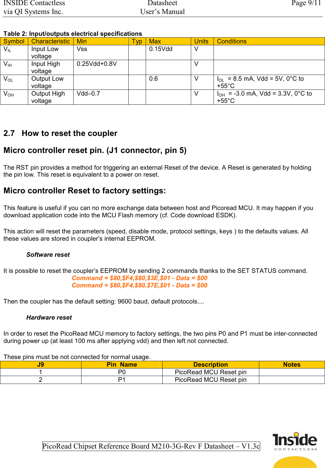
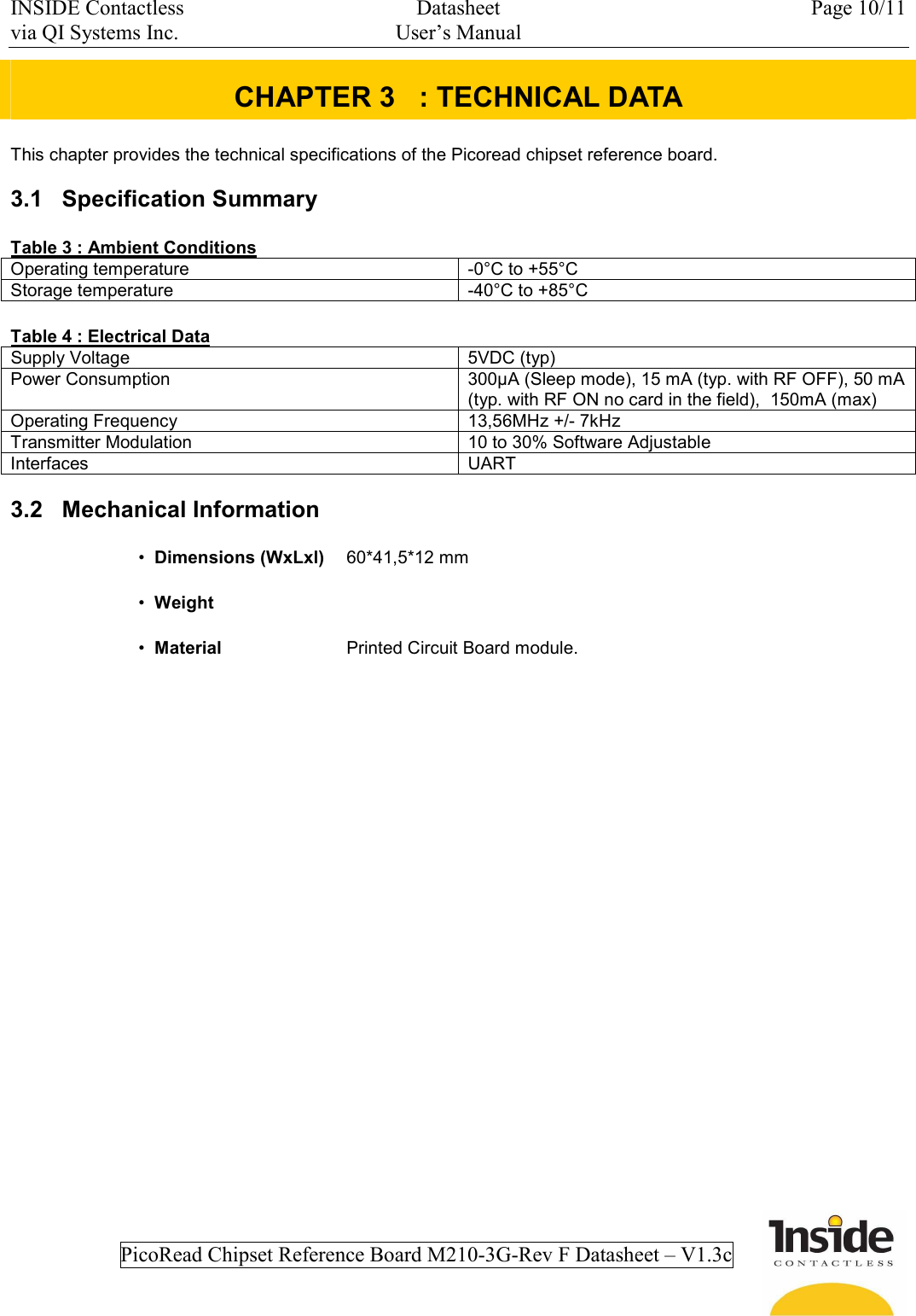
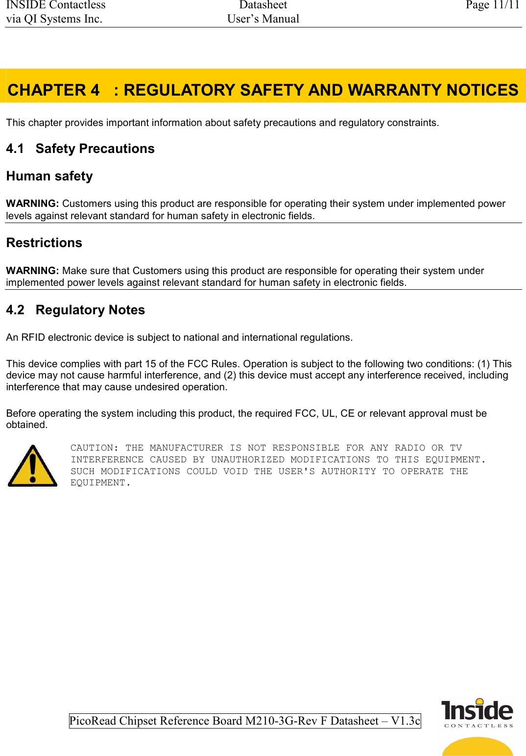
USERS MANUAL
Navigation menu
Upload a User Manual
Namespaces
Wiki Guide
HTML
PDF
Info
Views
User Manual
Discussion / Help
Navigation