QI Systems M210-3G RFID READER User Manual USERS MANUAL
QI Systems Inc. RFID READER USERS MANUAL
USERS MANUAL
INSIDE Contactless Datasheet Page 1/11
via QI Systems Inc. User’s Manual
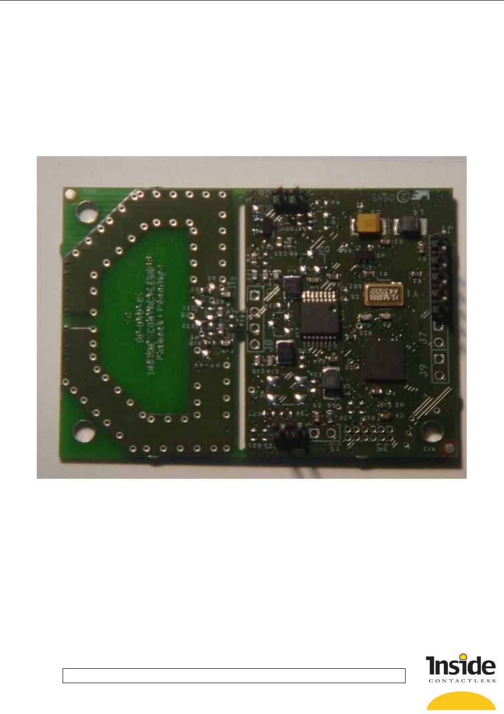
PicoRead Chipset Reference Board M210-3G-Rev F Datasheet – V1.3c
PICOREAD™ CHIPSET
Reference Board M210-3G-Rev F
User’s Guide

INSIDE Contactless Datasheet Page 2/11
via QI Systems Inc. User’s Manual
PicoRead Chipset Reference Board M210-3G-Rev F Datasheet – V1.3c
Version 1.3c
Author : OC
Date : November, 28th 2005
Modified: AL
-Added FCC Disclaimer & QI Systems in header
Date: April 4, 2007
Published by:
INSIDE Contactless
11A, Parc Club du Golf
13856 Aix-en-Provence Cedex 3
France
Tel.: +33 (0)4 42 39 63 00 - Fax: +33 (0)4 42 39 63 19
E-mail: info@insidefr.com - Web site: http://www.insidecontactless.com
INSIDE Contactless reserves the right to make changes, without notice, to any product herein
to improve reliability, functionality, or design. INSIDE Contactless advises its customers to
obtain the latest version of device data sheets to verify, before placing orders, that the
information being relied upon by the customer is current.
Information furnished by INSIDE Contactless is believed to be accurate and reliable. However,
INSIDE Contactless does not assume any liability resulting from the application or use of any
product described within.
INSIDE Contactless‘ products are not authorized for use as critical components in life support
devices or systems unless a specific written agreement pertaining to such intended use is
executed between the manufacturer and INSIDE Contactless board.
Life support devices or systems are devices or systems that (a) are intended for surgical
implant to the body or (b) support or sustain life, and whose failure to perform, when properly
used in accordance with instructions for use provided in the labeling, can be reasonably
expected to result in a significant injury to the user.
A critical component is any component of a life support device or system whose failure to
perform can be reasonably expected to cause the failure of the life support device or system,
or to affect its safety or effectiveness.
Brand and product names may be registered trademarks or trademarks of their respective
holders.
© INSIDE Contactless – 2005 - All rights reserved

INSIDE Contactless Datasheet Page 3/11
via QI Systems Inc. User’s Manual
PicoRead Chipset Reference Board M210-3G-Rev F Datasheet – V1.3c
CHAPTER 1 : PRODUCT DESCRIPTION.............................................................................................4
1.1 Introduction.......................................................................................................................................4
1.2 Main features....................................................................................................................................4
1.4 System integration............................................................................................................................5
CHAPTER 2 : PRODUCT SPECIFICATIONS & INSTALLATION ........................................................6
2.1 General.............................................................................................................................................6
2.2 Mechanical Information & Connectors (W*L*H): 41,5x60x12mm.....................................................6
2.3 Supply Connector : J1 ......................................................................................................................7
2.4 Antenna Connector : J8....................................................................................................................7
2.5 UART (RS232 logic CMOS) Connector : J1.....................................................................................8
2.6 Input/Outputs Connector : J2,J3.......................................................................................................8
2.7 How to reset the coupler...................................................................................................................9
Software reset..........................................................................................................................................9
Hardware reset.........................................................................................................................................9
CHAPTER 3 : TECHNICAL DATA ........................................................................................................10
3.1 Specification Summary....................................................................................................................10
3.2 Mechanical Information ...................................................................................................................10
CHAPTER 4 : REGULATORY, SAFETY AND WARRANTY NOTICES................................................11
4.1 Safety Precautions...........................................................................................................................11
Human safety..........................................................................................................................................11
Restrictions.............................................................................................................................................11
4.2 Regulatory Notes.............................................................................................................................11

INSIDE Contactless Datasheet Page 4/11
via QI Systems Inc. User’s Manual
PicoRead Chipset Reference Board M210-3G-Rev F Datasheet – V1.3c
About this manual
This product description is written for PicoRead Chipset Reference Board users and integrators.
Abstract
The PicoRead Chipset reference board is a low-cost, low power, multi-standard 13.56 MHz contactless coupler.
CHAPTER 1 : PRODUCT DESCRIPTION
1.1 Introduction
The Picoread Chipset reference board is a low-cost 13.56 MHz contactless coupler compliant with ISO 14443
A&B and ISO 15693 standards and with capability to communicate with FeliCa™ chips. By operating in
transparent mode, the board allows communication with any chip compliant with these standards.
1.2 Main features
• ISO14443 A&B, ISO15693 and FeliCa™
• Operating distance up to 6 cm
• Small size: 6 x 4.2 cm with on board antenna (3 x 4,2 cm when the antenna is removed)
• Low power: 50 mA in active mode / 300 µA in sleep mode
• Automatic card detection from sleep mode
• Cryptographic security management
• Easy system integration
• Serial interface to standard micro controllers
• Extra memory space for application software download
• 250 bytes communication buffer
• Evaluation kit available
INSIDE Contactless Datasheet Page 5/11
via QI Systems Inc. User’s Manual
PicoRead Chipset Reference Board M210-3G-Rev F Datasheet – V1.3c
Product Ordering Code
Product Ordering code Package Description
PicoRead Chipset
Reference Board
M210-3G U03 PCB
13,56 Mhz coupler
PicoRead Chipset Kit PicoRead Chipset
U03
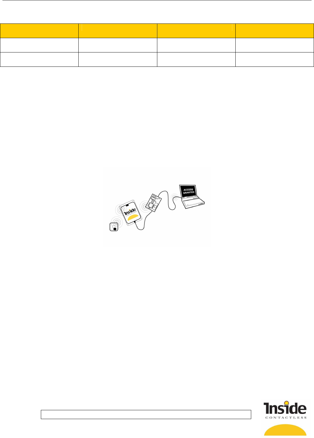
1.4 System integration
Two different modes are available:
• Connected mode: the PicoRead Chipset reference board acts as a coupler and process commands
requested by a host system (PC, PLC,µC...)
• Stand alone mode: the PicoRead Chipset reference board executes application code from internal flash
memory. Refer to the Embedded Software Development Kit (ESDK tool).
INSIDE Contactless Datasheet Page 6/11
via QI Systems Inc. User’s Manual
PicoRead Chipset Reference Board M210-3G-Rev F Datasheet – V1.3c
CHAPTER 2 : PRODUCT SPECIFICATIONS & INSTALLATION
2.1 General
This chapter provides a description of the product hardware. It also provides the electrical specifications of inputs
and outputs.
Important care must be taken during the coupler mounting. Bad connection may
damage the coupler or the power supply.
Make sure that the power is switched off during coupler mounting and cable
connection.
The product has been designed with easy installation in mind. The following information provides you with any
details that you will need to know.
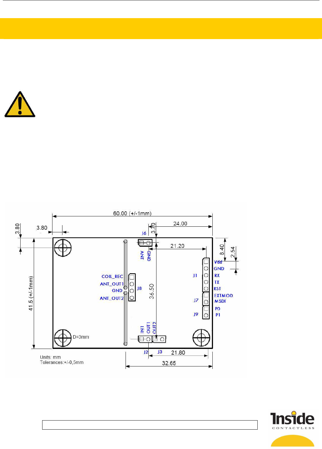
2.2 Mechanical Information & Connectors (W*L*H):
41,5x60x12mm
Mounting is accomplished using the three 3 mm holes located on the module corners.
Figure 1
INSIDE Contactless Datasheet Page 7/11
via QI Systems Inc. User’s Manual
PicoRead Chipset Reference Board M210-3G-Rev F Datasheet – V1.3c
2.3 Supply Connector: J1
The PicoRead chipset reference board must be powered using connector J1.
J1 Pin Name Description Notes
1 Vdd Positive supply voltage VDC
2 Gnd 0 volts
Parameter Min Typical Max
Supply voltage VDC 4.5 VDC 5VDC 5.5VDC
Supply Current ICC 50mA 150mA
Ripple 20mV
Sleep mode 300µA
Table 1: Supply connector specification
CAUTIONS:
• Reversing the power supply may destroy the device
• There is no over current protection on the board itself. Make sure that it exists on the power
supply unit.
• If you are using a switch power supply you must ensure that the switching frequency is below
100kHz or above 1Mhz. Such a supply may generate noise, add communication holes and
reduce read range.
• Linear power supplied must be used to get the best performances from the reference board.
2.4 Antenna Connector: J8
The PicoRead chipset reference design has been also designed for custom antenna connection using J8
connector.
J8 Pin Name Description Notes
1 Coil Rec Antenna Coil Input
2 Ant_Out1 PicoRead RF ANT1 output 1
3 Gnd 0 volts
4 Ant_Out2 PicoRead RF ANT2 output 1
Note 1: A 16Mhz low pass LC Filter is inserted between the PicoRead RF output and this pin.
CAUTIONS:
Refer to the “PicoRead Chipset Datasheet” and Applications Notes for antenna design rules.
Refer to the PicoRead Chipset Reference design Application Note for schematics and components
details.
INSIDE Contactless Datasheet Page 8/11
via QI Systems Inc. User’s Manual
PicoRead Chipset Reference Board M210-3G-Rev F Datasheet – V1.3c
2.5 UART (RS232 logic CMOS) Connector: J1
The PicoRead MCU provides a standard Universal Asynchronous Receiver Transmitter.
It allows configurable High Speed half duplex communication with host through the RX and TX pins.
Refer to the Inside Reference Manual for details regarding the byte and frame format.
J1 Pin Name Description Notes
1 Vdd Positive supply voltage
2 Gnd Ground, 0v
3 Rx PicoRead MCU UART Input
Receive Data Line (must be connected to the host
transmit data line)
4 Tx PicoRead MCU UART
Output
Transmit Data Line (must be connected to the host
Receive Data line)
5 RST
2.6 Input/Outputs Connector: J2,J3
1 digital input (IN1) and 2 outputs (OUT1, OUT2) are available on the Picoread MCU for general purpose use.
These I/Os are located on J2 and J3 connectors.
J2 Pin Name Description Notes
1 IN1 Logic Input
2 OUT1 Logic Output 2
J3 Pin Name Description Notes
1 OUT2 Logic Output 2
2 1kOhm Pulled up to Vdd Can be used for led connection
Note 2: Make sure that current on those pins does not exceed +/- 20mA.
INSIDE Contactless Datasheet Page 9/11
via QI Systems Inc. User’s Manual
PicoRead Chipset Reference Board M210-3G-Rev F Datasheet – V1.3c
Table 2: Input/outputs electrical specifications
Symbol
Characteristic
Min Typ
Max Units Conditions
V
IL
Input Low
voltage
Vss 0.15Vdd V
V
IH
Input High
voltage
0.25Vdd+0.8V V
V
OL
Output Low
voltage
0.6 V I
OL
= 8.5 mA, Vdd = 5V, 0°C to
+55°C
V
OH
Output High
voltage
Vdd–0.7 V I
OH
= -3.0 mA, Vdd = 3.3V, 0°C to
+55°C
2.7 How to reset the coupler
Micro controller reset pin. (J1 connector, pin 5)
The RST pin provides a method for triggering an external Reset of the device. A Reset is generated by holding
the pin low. This reset is equivalent to a power on reset.
Micro controller Reset to factory settings:
This feature is useful if you can no more exchange data between host and Picoread MCU. It may happen if you
download application code into the MCU Flash memory (cf. Code download ESDK).
This action will reset the parameters (speed, disable mode, protocol settings, keys ) to the defaults values. All
these values are stored in coupler’s internal EEPROM.
Software reset
It is possible to reset the coupler’s EEPROM by sending 2 commands thanks to the SET STATUS command.
Command = $80,$F4,$80,$3E,$01 - Data = $00
Command = $80,$F4,$80,$7E,$01 - Data = $00
Then the coupler has the default setting: 9600 baud, default protocols....
Hardware reset
In order to reset the PicoRead MCU memory to factory settings, the two pins P0 and P1 must be inter-connected
during power up (at least 100 ms after applying vdd) and then left not connected.
These pins must be not connected for normal usage.
J9 Pin Name Description Notes
1 P0 PicoRead MCU Reset pin
2 P1 PicoRead MCU Reset pin
INSIDE Contactless Datasheet Page 10/11
via QI Systems Inc. User’s Manual
PicoRead Chipset Reference Board M210-3G-Rev F Datasheet – V1.3c
CHAPTER 3 : TECHNICAL DATA
This chapter provides the technical specifications of the Picoread chipset reference board.
3.1 Specification Summary
Table 3 : Ambient Conditions
Operating temperature -0°C to +55°C
Storage temperature -40°C to +85°C
Table 4 : Electrical Data
Supply Voltage 5VDC (typ)
Power Consumption 300µA (Sleep mode), 15 mA (typ. with RF OFF), 50 mA
(typ. with RF ON no card in the field), 150mA (max)
Operating Frequency 13,56MHz +/- 7kHz
Transmitter Modulation 10 to 30% Software Adjustable
Interfaces UART
3.2 Mechanical Information
• Dimensions (WxLxl) 60*41,5*12 mm
• Weight
• Material Printed Circuit Board module.
INSIDE Contactless Datasheet Page 11/11
via QI Systems Inc. User’s Manual
PicoRead Chipset Reference Board M210-3G-Rev F Datasheet – V1.3c
CHAPTER 4 : REGULATORY SAFETY AND WARRANTY NOTICES
This chapter provides important information about safety precautions and regulatory constraints.
4.1 Safety Precautions
Human safety
WARNING: Customers using this product are responsible for operating their system under implemented power
levels against relevant standard for human safety in electronic fields.
Restrictions
WARNING: Make sure that Customers using this product are responsible for operating their system under
implemented power levels against relevant standard for human safety in electronic fields.
4.2 Regulatory Notes
An RFID electronic device is subject to national and international regulations.
This device complies with part 15 of the FCC Rules. Operation is subject to the following two conditions: (1) This
device may not cause harmful interference, and (2) this device must accept any interference received, including
interference that may cause undesired operation.
Before operating the system including this product, the required FCC, UL, CE or relevant approval must be
obtained.
CAUTION: THE MANUFACTURER IS NOT RESPONSIBLE FOR ANY RADIO OR TV
INTERFERENCE CAUSED BY UNAUTHORIZED MODIFICATIONS TO THIS EQUIPMENT.
SUCH MODIFICATIONS COULD VOID THE USER'S AUTHORITY TO OPERATE THE
EQUIPMENT.