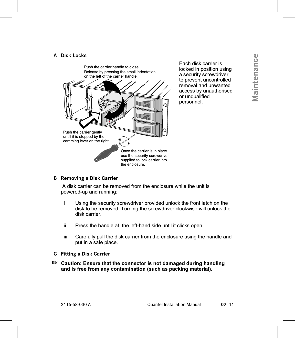
QUANTEL 2116-914M IQ Hand Control Unit (RAT) User Manual
QUANTEL LTD IQ Hand Control Unit (RAT) Users Manual
UserManual.wiki
>
QUANTEL
>
2116 914M User Manual
Users Manual
Navigation menu
Upload a User Manual
Namespaces
Wiki Guide
HTML
PDF
Info
Views
User Manual
Discussion / Help
Navigation
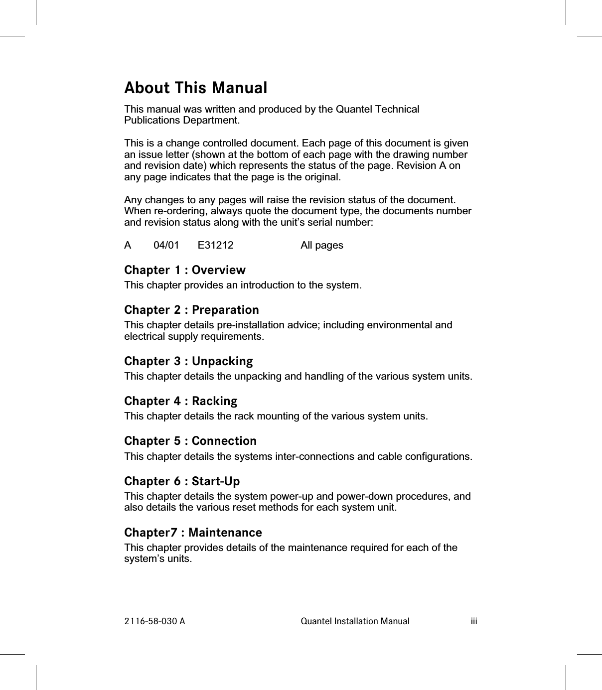


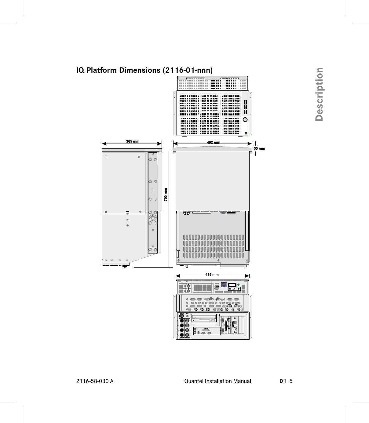

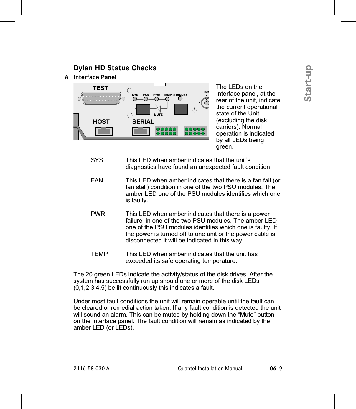
![GeneralEquipment LocationThe cabinet required tohouse the system is astandard 19 inch (483mm) width withdimensions as detailedin the diagram.The cabinet must besituated such thatsufficient access space(1 metre if possible) isprovided at both sidesand the rear of thecabinets as detailed inthe diagram. Values of[a] to [e] in the diagrammust be correct to allowthe system’s units to becorrectly installed andto allow maintenance tobe performed.The system is suppliedwith a rack mounting kitfor each unit andincludes rack slides andreinforcing plates to befitted as described inthe “Racking” chapter.Note access toCD-ROM at rear isrequired for servicingpurposes. The CD trayextends 140mm fromthe rear of the unit.2116-58-030 A Quantel Installation Manual 02 3PreparationRear DoorIf Fitted ShouldBe Ventilated[a] 450 mmMinimum ApertureBetween RackMounting Angles[b] Allow 740 mmFor Cablingand Ventilation[d] 300 mm Minimum500 mm Preferred[e] 60 mmMaximum[c] Allow 400 mmMinimum For SideAccess To PCBSIn MainframeFront of CabinetRear Rack MountingAngles Should BeAdjustable](https://usermanual.wiki/QUANTEL/2116-914M/User-Guide-219973-Page-23.png)
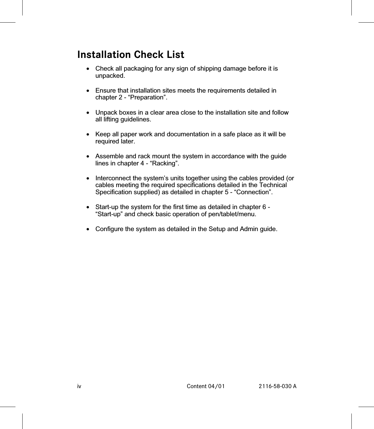
![[a] The smallest aperture into which a unit can be fitted.[b] The internal depth of the cabinet must exceed this value to ensure correctventilation.[c] The distance from the side of the unit and any obstruction (such as a wallor pillar) must be greater than this value to allow access to the side mountedPCBs in the unit.[d] The distance from the rear of the cabinet and any obstruction (such as awall or another cabinet) must be greater than this value to ensure correctairflow through the units and allow access.[e] The distance between the front of the rack mounting bars and theabsolute front of the cabinet must not exceed this value otherwise access tothe side mounted PCBs is not possible.The cabling should be carried out using the cables provided or using theshortest possible lengths, to avoid interference from stray electromagneticfields.The cabinets should be fitted with units from bottom to top to prevent thecabinets falling forward.It is strongly recommended that cabinets with extending feet are used toensure that the cabinet remains stable during installation and during anymaintenance.☛WARNING (WI 2) Rack Slides - Never have more than one equipmentunit on extended rack slides as this may cause the cabinet to fallresulting in personal injury and possible other damage. (12/97)02 4 Preparation 04/01 2116-58-030 APreparation](https://usermanual.wiki/QUANTEL/2116-914M/User-Guide-219973-Page-24.png)