QUANTEL 2116-914M IQ Hand Control Unit (RAT) User Manual
QUANTEL LTD IQ Hand Control Unit (RAT) Users Manual
QUANTEL >
Users Manual

iQ System
Installation Manual
Model Number: 2116-01-nnn
Notice
Quantel Limited accepts no
responsibility for the accuracy of the
information contained herein and
reserves the right to change the
contents without prior notice. This
document does not form part of the
product’s Technical or Functional
Specification and does not form part of
any contractual agreement.
This manual is a change controlled
document. Please quote the revision
status of this manual when re-ordering.
The revision status is determined by the
content, any change in any part being
reflected in the manual revision status.
This Manual is Revision A.
Copyright © Quantel Ltd 2000-2001
2116-58-030 A Quantel Installation Manual i

Notices
Important Product Information
WARNING: Read the Important Product
Information book before use.
Conventions Used
☛WARNINGS: Indicate danger to life and limb if the indicated statements
are ignored, or the indicated procedures are not performed correctly.
☞Cautions: Indicate possible damage to (or misalignment of) the
equipment if the indicated statements are ignored, or the indicated
procedures are not performed correctly.
Maintenance
☛WARNING (WM 2) Service Personnel - Maintenance and Calibration
within the equipment enclosure is only to be carried out by SERVICE
PERSONNEL. (12/97)
Equipment Isolation
☛WARNING (WI 5) Equipment Isolation - The plug on the power supply
cord, for Pluggable Equipment, is considered to be the isolation device
and therefore the socket-outlet must be installed near the equipment
and shall always be accessible for this purpose. For permanently
connected equipment, where the unit’s mains supply inlet is
permanently connected, a readily accessible disconnect device must
be incorporated in the fixed wiring. (12/97)
Trade Marks
Most of the product names mentioned in this manual are manufacturer trade
marks and are used within this manual only for the purpose of identification.
iQ is a registered trademark is of Quantel Limited.
ii Content 04/01 2116-58-030 A
About This Manual
This manual was written and produced by the Quantel Technical
Publications Department.
This is a change controlled document. Each page of this document is given
an issue letter (shown at the bottom of each page with the drawing number
and revision date) which represents the status of the page. Revision A on
any page indicates that the page is the original.
Any changes to any pages will raise the revision status of the document.
When re-ordering, always quote the document type, the documents number
and revision status along with the unit’s serial number:
A 04/01 E31212 All pages
Chapter 1 : Overview
This chapter provides an introduction to the system.
Chapter 2 : Preparation
This chapter details pre-installation advice; including environmental and
electrical supply requirements.
Chapter 3 : Unpacking
This chapter details the unpacking and handling of the various system units.
Chapter 4 : Racking
This chapter details the rack mounting of the various system units.
Chapter 5 : Connection
This chapter details the systems inter-connections and cable configurations.
Chapter 6 : Start-Up
This chapter details the system power-up and power-down procedures, and
also details the various reset methods for each system unit.
Chapter7 : Maintenance
This chapter provides details of the maintenance required for each of the
system’s units.
2116-58-030 A Quantel Installation Manual iii
Installation Check List
•Check all packaging for any sign of shipping damage before it is
unpacked.
•Ensure that installation sites meets the requirements detailed in
chapter 2 - “Preparation”.
•Unpack boxes in a clear area close to the installation site and follow
all lifting guidelines.
•Keep all paper work and documentation in a safe place as it will be
required later.
•Assemble and rack mount the system in accordance with the guide
lines in chapter 4 - “Racking”.
•Interconnect the system’s units together using the cables provided (or
cables meeting the required specifications detailed in the Technical
Specification supplied) as detailed in chapter 5 - “Connection”.
•Start-up the system for the first time as detailed in chapter 6 -
“Start-up” and check basic operation of pen/tablet/menu.
•Configure the system as detailed in the Setup and Admin guide.
iv Content 04/01 2116-58-030 A
Contents
01 - Description
Overview 1-3
System Components 1-3
IQ Platform 1-3
Dylan HD Disk Arrays 1-3
IQ Workstation 1-3
IQ Platform Dimensions
(2116-01-nnn) 1-5
Dylan HD Dimensions (2110-12-nnn
Serial) 1-6
Tablet Dimensions 1-7
Keyboard Dimensions 1-8
Hand Unit & Docking Port Dimensions
1-9
Control Interface Box Dimensions1-10
Fader Panel Dimensions 1-11
Jog / Shuttle Panel Dimensions 1-12
02 - Preparation
General 2-3
Equipment Location 2-3
System Air Flow 2-5
Electrical Supply 2-7
Description 2-7
Electrical Supply Quality 2-8
Environment 2-9
Operating Environment 2-9
Shipment & Storage Environment2-10
03 - Unpacking
General 3-3
Unpacking Advice 3-3
iQ Platform 3-3
04 - Racking
Rack Mounting 4-3
Important Information 4-3
Rack Layout 4-4
IQ Platform Rack Mounting Procedure
4-5
Dylan HD Disk Arrays 4-9
Fitting the Rails to the Cabinet
4-9
Securing the Enclosure to the Rails
4-10
Fitting the PSU Modules 4-11
Fitting the Interface Module 4-12
Fitting the Disk Carriers 4-13
Workstation 4-15
Workstation Layout 4-15
Mounting the Tablet 4-15
Mounting the Keyboard 4-15
Mounting the Fader Panel 4-16
Mounting the Jog / Shuttle Panel 4-16
Assembling the Hand Unit / Mounting
the Docking Port 4-16
Important Battery Information4-16
2116-58-030 A Quantel Installation Manual v
05 - Connection
System Connection 5-3
System Connection Overview 5-3
Electrical Supply Considerations 5-4
Cabling Considerations 5-4
IQ Platform 5-5
Rear Panel Layout 5-5
Mains Connection 5-5
Digital Video Connections 5-6
General 5-6
SD Video Inputs and Outputs 5-6
HD Video Inputs and Outputs 5-7
Serial Control Connections 5-7
General 5-7
VCR Connections 5-8
Workstation Connection 5-8
SCSI Port 5-8
Locking References 5-9
SVGA Monitor Output 5-10
Analogue Audio Monitor 5-11
Digital Audio Connections 5-11
Fibre Optic Connection 5-12
Description 5-12
Important Information 5-12
Connection 5-12
Disconnection 5-12
Attention Connection 5-13
Description 5-13
Dylan HD 5-15
Back Panel Details 5-15
Mains Connection 5-15
Host Connection 5-15
Workstation 5-17
Inter-connection 5-17
06 - Start-up
Startup & Shutdown Procedures
6-3
IQ Platform 6-3
Initial Start-up 6-3
Normal Start-up 6-3
Power-down Procedure 6-4
Dylan HD 6-5
Initial Start-up 6-5
Normal Start-up 6-5
Power-Down Procedure 6-5
System Reset 6-6
System Status 6-7
Correct Operation 6-7
IQ Platform 6-7
Dylan HD Status Checks 6-9
Interface Panel 6-9
Disk Carriers 6-10
Workstation 6-10
Control Interface Box 6-10
Tablet 6-11
Fader Panel 6-11
Jog / Shuttle Panel 6-11
Keyboard 6-11
Hand Unit / Docking Port 6-11
vi Content 04/01 2116-58-030 A
07 - Maintenance
Routine Maintenance 7-3
Workstation 7-3
Tablet Care 7-3
Pen Care 7-3
Changing the Pen Nib 7-4
Fibre Optic Connections 7-4
Corrective Maintenance 7-5
Important User Information 7-5
Information for Service Personnel7-5
iQ Platform Configuration 7-5
Links and Switches 7-5
Image Processor Unit Board
Locations 7-6
PC Sub-system 7-6
Carrier Assembly 7-7
Removing the PC Sub-system 7-8
Hot Changing a Dylan HD PSU Module
7-9
Removing a PSU Module with the
Power On 7-9
Fitting a PSU Module with the
Power On 7-10
Hot Changing a Dylan HD Disk Carrier
7-10
Disk Locks 7-11
Removing a Disk Carrier 7-11
Fitting a Disk Carrier 7-11
2116-58-030 A Quantel Installation Manual vii
viii Content 04/01 2116-58-030 A

iQ System
Installation Manual
01 - Description
2116-58-030 A Quantel Installation Manual 01 1
Description
01 2 Description 04/01 2116-58-030 A
Description
Overview
System Components
A IQ Platform
The iQ Platform is an 8U, 19 inch rack unit containing the system’s major
electronic circuitry, disk storage and power supply.
The rack unit is divided into three compartments; The top compartment
holding a PSU; the front compartment holding the image processing circuitry
and the unit’s disk storage and the rear compartment holding an ATX PC
motherboard, CD-ROM drive, ATX power supply and PCI printed circuit
boards.
☞Note that the Quantel iQ platform and operating system are designed
only to run content creation packages developed using the Quantel iQ
SDK.
B Dylan HD Disk Arrays
The Dylan HD units allow the system to store standard video (SD) and high
definition video (HD) in the ‘Native Format’ in which it was originated. This
video is processed by the iQ Platform in real time whatever the field/frame
rate, aspect ratio, bit depth or colour space. Each Dylan HD is a 4U disk
array containing 12 disk drives and two independent power supply modules.
C IQ Workstation
The iQ Workstation consists of a tablet & pen, a qwerty keyboard, a hand
unit with docking port, a fader panel and jog/shuttle panel. These in
conjunction with the systems monitor output for on-screen menu displays
provide the system’s user interface.
Digitising Tablet & Pen: These provide the positional co-ordinates and
pressure information for the system for use with the on-screen menus and
direct editing.
Keyboard: Provides text entry, macro setup and other shortcuts.
2116-58-030 A Quantel Installation Manual 01 3
Description
Hand Unit: A supplementary device allowing additional control to that of the
menu structure via the thumb-switch and four buttons. A docking port may
be supplied for remote control and to allow the Hand Unit to re-charged
when not in use.
☞Note that the docking port can only be supplied where local
regulations permit the use of the specific radio frequency employed by
the Hand Unit and docking port. In these cases the Hand Unit
connected via a cable.
Fader Panel: A unit providing manual control over audio edits, consisting of
8 dynamic level controls, master level control, pan control knobs and track
mute switches.
Jog/Shuttle Panel: Another supplementary device which can be used for
navigation through clips freeing up the pen and tablet for menu selection.
01 4 Description 04/01 2116-58-030 A
Description
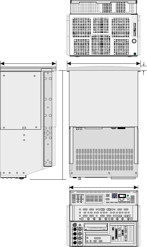
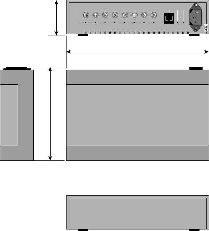
IQ Platform Dimensions (2116-01-nnn)
2116-58-030 A Quantel Installation Manual 01 5
Description
365 mm
700 mm
435 mm
482 mm
55 mm
HD IN
SD IN
HD OUT
SD OUT
HD OUT
SD OUT
SD IN
HD IN
DISK A DISK B
CPU A CPU B
ATTENTION
A
REF IN
B
REF OUT
TX
RX
VGA 1
LINK A
RAID
W/S
VGA 2
LINK B
VTR B
VTR A
KB L
MOUSE
WORD
KBD USB
1
0
PARALLEL
CLOCK
MONITOR
AES/EBU OUTAES/EBU IN
1/2
3/4
5/6
7/8
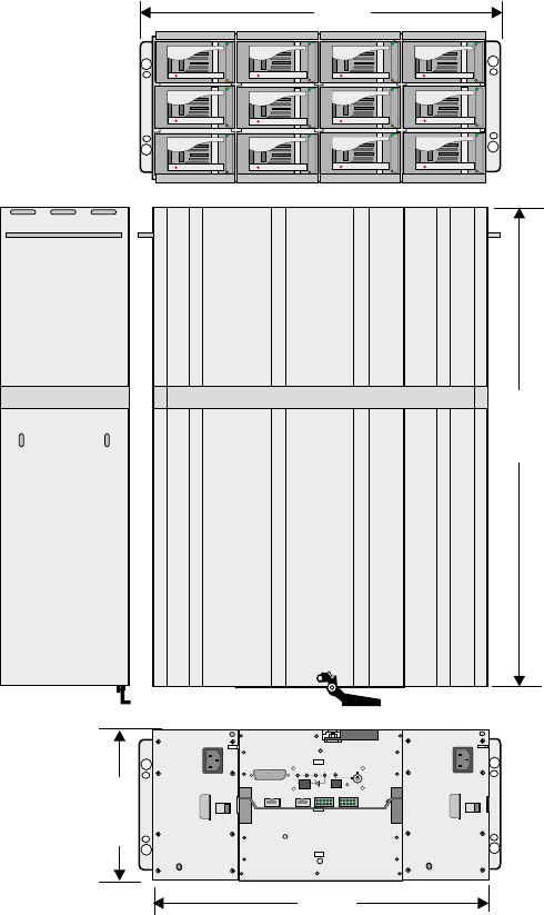
Dylan HD Dimensions (2110-12-nnn Serial)
01 6 Description 04/01 2116-58-030 A
Description
447 mm
571.5mm
176.3mm
482 mm
TEST
SERIAL HOST
SYS FAN
RUN
PWR
MUTE
TEMP STANDBY

Tablet Dimensions
2116-58-030 A Quantel Installation Manual 01 7
Description
365mm
470mm
12mm
5mm
15mm
20mm
152mm
12mm
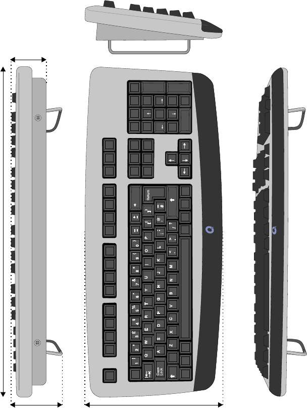
Keyboard Dimensions
01 8 Description 04/01 2116-58-030 A
Description
Shift Shift
|
\
Home
F1 F2 F3 F4 F5 F6 F7 F8 F9 F10 F13
Insert Num
Lock
Delete
Home
End
F11 F14
Home /
End
F12 F15
Page
Up *-
+
Enter
Page
Down PgUp
PgDn
Backspace
Esc
Alt
Alt
Ctrl Ctrl
7
1
8
2
9
3
4
0
56
.
Ins
Del
485mm
90
mm
60mm
21
0
mm
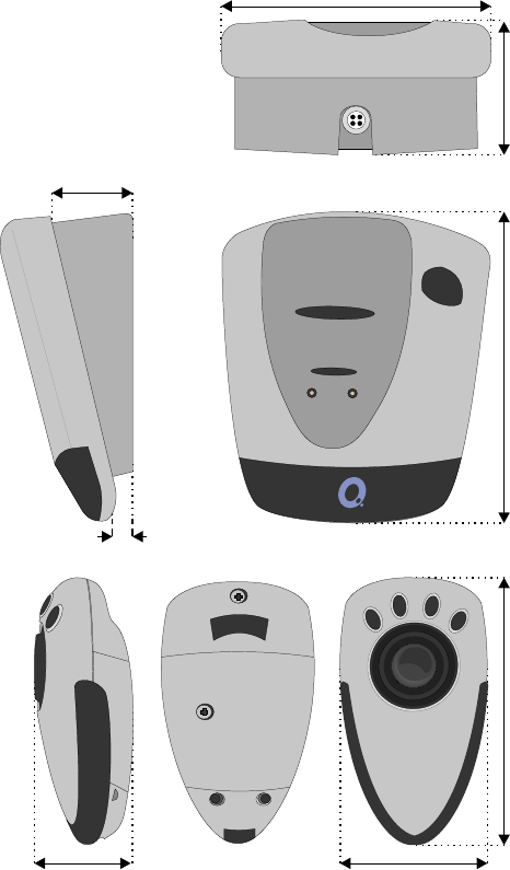
Hand Unit & Docking Port Dimensions
Note that the docking port may not be supplied in some countries.
2116-58-030 A Quantel Installation Manual 01 9
Description
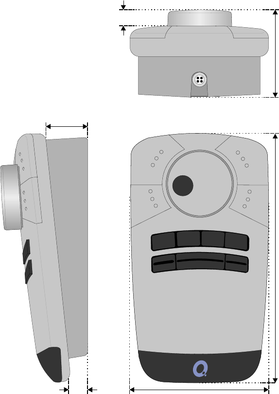
110
mm
30mm
10mm
58
mm4
3
mm
50mm 135mm 105mm
Control Interface Box Dimensions
01 10 Description 04/01 2116-58-030 A
Description
M/F
O/L
OK
O/L W/S
60mm
233mm
160mm
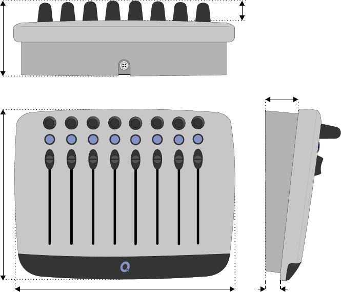
Fader Panel Dimensions
2116-58-030 A Quantel Installation Manual 01 11
Description
235mm
35mm
15mm
25mm
21
0
mm
80mm
Jog / Shuttle Panel Dimensions
01 12 Description 04/01 2116-58-030 A
Description
11
5
mm
35mm
15mm
15mm
210mm 75mm

iQ System
Installation Manual
02 - Preparation
2116-58-030 A Quantel Installation Manual 02 1
Preparation
02 2 Preparation 04/01 2116-58-030 A
Preparation
General
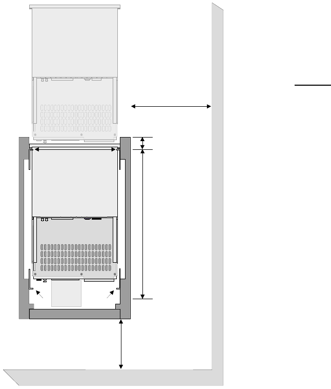
Equipment Location
The cabinet required to
house the system is a
standard 19 inch (483
mm) width with
dimensions as detailed
in the diagram.
The cabinet must be
situated such that
sufficient access space
(1 metre if possible) is
provided at both sides
and the rear of the
cabinets as detailed in
the diagram. Values of
[a] to [e] in the diagram
must be correct to allow
the system’s units to be
correctly installed and
to allow maintenance to
be performed.
The system is supplied
with a rack mounting kit
for each unit and
includes rack slides and
reinforcing plates to be
fitted as described in
the “Racking” chapter.
Note access to
CD-ROM at rear is
required for servicing
purposes. The CD tray
extends 140mm from
the rear of the unit.
2116-58-030 A Quantel Installation Manual 02 3
Preparation
Rear Door
If Fitted Should
Be Ventilated
[a] 450 mm
Minimum Aperture
Between Rack
Mounting Angles
[b] Allow 740 mm
For Cabling
and Ventilation
[d] 300 mm Minimum
500 mm Preferred
[e] 60 mm
Maximum
[c] Allow 400 mm
Minimum For Side
Access To PCBS
In Mainframe
Front of Cabinet
Rear Rack Mounting
Angles Should Be
Adjustable
[a] The smallest aperture into which a unit can be fitted.
[b] The internal depth of the cabinet must exceed this value to ensure correct
ventilation.
[c] The distance from the side of the unit and any obstruction (such as a wall
or pillar) must be greater than this value to allow access to the side mounted
PCBs in the unit.
[d] The distance from the rear of the cabinet and any obstruction (such as a
wall or another cabinet) must be greater than this value to ensure correct
airflow through the units and allow access.
[e] The distance between the front of the rack mounting bars and the
absolute front of the cabinet must not exceed this value otherwise access to
the side mounted PCBs is not possible.
The cabling should be carried out using the cables provided or using the
shortest possible lengths, to avoid interference from stray electromagnetic
fields.
The cabinets should be fitted with units from bottom to top to prevent the
cabinets falling forward.
It is strongly recommended that cabinets with extending feet are used to
ensure that the cabinet remains stable during installation and during any
maintenance.
☛WARNING (WI 2) Rack Slides - Never have more than one equipment
unit on extended rack slides as this may cause the cabinet to fall
resulting in personal injury and possible other damage. (12/97)
02 4 Preparation 04/01 2116-58-030 A
Preparation
System Air Flow
The air flow through the iQ Platform is front to back, that is air is drawn
through the front panels of each unit and expelled at the rear of the unit. The
cabinets that are to hold the system should be located carefully to ensure
adequate clearance to provide for the correct cooling of the system.
If the system is operated in a confined area, additional external forced air
cooling may be required.
☞Caution (CI 1) Equipment Ventilation - Ensure that hot air expelled from
one unit is not drawn into another as this may cause overheating and
subsequent damage. (12/97)
2116-58-030 A Quantel Installation Manual 02 5
Preparation
02 6 Preparation 04/01 2116-58-030 A
Preparation

Electrical Supply
Description
☛WARNING (WI 6) Earthing - The equipment must be reliably connected
to earth. (12/97)
The cables supplied with the equipment should be connected directly
(shortest cable length) to an earthed electrical supply outlet.
American Standard: Black Live
White Neutral
Green Earth
European Standard Brown Live
Blue Neutral
Green/Yellow Earth
This product is a Class 1 apparatus (as defined in IEC 536) and its
accessible conductive parts must always be connected to the protective
(earthing) conductor of the supply installation by the green or green/yellow
conductor of the supplied 3-core cable, to ensure continued safety of both
apparatus and user. The supply installation should be protected so as to
safely interrupt prospective short circuit currents at the apparatus in excess
of 300 A.
Quantel supplies a 3-core Mains cordset, of the correct current rating, with
each item of equipment it despatches. These are full moulded assemblies
with a socket to IEC 320 sheet C13 or C19 at the equipment end and a plug
to either BS 1363 (for the UK market), CEE 7/7 (for much of the European
market), or NEMA 5-15 (for the US and Japanese markets).
Should it prove necessary to replace or modify a Mains cordset provided by
Quantel, either through loss, damage or incompatibility with local outlets, do
so only with an approved item of equal or higher electrical ratings which also
complies with local regulations for materials and construction (for example,
the UK IEE regulations or the US NEC).
2116-58-030 A Quantel Installation Manual 02 7
Preparation
In particular, the plug to be used in the following countries should comply
with the listed standards:
Austria: A5 3112
Denmark: Heavy current regulations AFSNIT 107-2-D.
DO NOT USE THE STANDARD EUROPEAN CEE 7/7 PLUG; although
the live and neutral pins will make contact, THE EQUIPMENT WILL NOT
BE GROUNDED.
INDIA: BS 546
ISRAEL: IS 32
ITALY: CEI 23-16/VII
RUSSIA: GOST 7396
SWITZERLAND: SEV 1011, SEV 6534-2. 1991
The colour coding of the conductors within the cordset supplied by Quantel
will comply with one of 2 colour coded cable types detailed previously.
Modifications to the cordset must only be undertaken by suitably qualified
persons. Any plug cut off during modification must be disposed of safety;
making it unusable and preventing any hazards arising from its re-use such
as accidental insertion into a mains outlet.
Electrical Supply Quality
It is recommended that the unit is connected to a “Technical Electrical
Supply”; free from interference and low frequency transients etc. The
electrical supply should be clean and sinusoidal, to prevent large transient
currents during the peaks of the supply cycle.
02 8 Preparation 04/01 2116-58-030 A
Preparation
Environment
Operating Environment
Care should be taken in the choice of installation environment to ensure
reliability. The following points should be remembered when installing the
system, to minimize possible failure:
iAvoid installations near sources of direct heat and avoid exposure to
direct sunlight or any other strong direct lights. These may cause heat
build-up within the unit.
ii Ensure that good air circulation around the rack is provided to prevent
heat build-up. Air holes should be given adequate clearance. Ensure
that no ventilation holes on the unit are restricted, because over
heating will occur.
iii Ensure that power and data cables are not run together and that they
are tied back to avoid obstructing the air flow.
iv Avoid areas where large temperature changes are possible as this
may unduly stress components, and may also cause condensation
damage to the system’s magnetic disk media.
vAvoid areas subject to vibration and areas where dust contamination
is possible.
vi It is recommended that the unit is connected to a “Technical Electrical
Supply”; free from interference and low frequency transients etc. The
electrical supply should be clean and sinusoidal, to prevent large
transient currents when the unit’s switch mode power supply unit is in
operation.
☞Caution (CT 2) Static Discharges - The Integrated Circuits and other
components within the equipment can be irreparably damaged by
static fields or discharge. Therefore, adequate precautions must be
taken to prevent possible damage. (12/97)
2116-58-030 A Quantel Installation Manual 02 9
Preparation

Shipment & Storage Environment
Before powering up the equipment it must be given the minimum
acclimatization time in the operating environment. Powering up the
equipment before it has had time to acclimatize may cause damage due to
condensation.
If the equipment has just been received or removed from a climate with
temperatures at or below 50°F (10°C), do not open the container until the
following conditions are met, otherwise condensation could occur and
damage to the equipment result. Place packing in the operating environment
for the time duration indicated below.
Previous Temperature Acclimatising Time
+40°F +4°C 13 Hours
+30°F -1°C 15 Hours
+20°F -7°C 16 Hours
+10°F-12°C 17 Hours
0°F-18°C 18 Hours
-10°F -23°C 20 Hours
-20°F -29°C 22 Hours
-20°F -34°C 27 Hours
02 10 Preparation 04/01 2116-58-030 A
Preparation

iQ System
Installation Manual
03 - Unpacking
2116-58-030 A Quantel Installation Manual 03 1
Unpacking
03 2 Unpacking 04/01 2116-58-030 A
Unpacking
General
Unpacking Advice
The various sections of this document detail the unpacking and handling of
equipment as it was delivered. Use the shipping list and the content guide to
check that all contents are correct and that no damage has occurred in
transit.
Care should be taken when unpacking the equipment, to ensure that all
packing material is removed, from around the individual units and their
connectors.
☛WARNING (WT 1) Heavy or Bulky Equipment - This equipment may be
heavy or have awkward dimensions. Attempting to lift or move the
equipment may cause personal injury if due care and consideration are
not taken. Before attempting, read any unpacking/handling instructions
and always comply with the Health & Safety rules. (12/97).
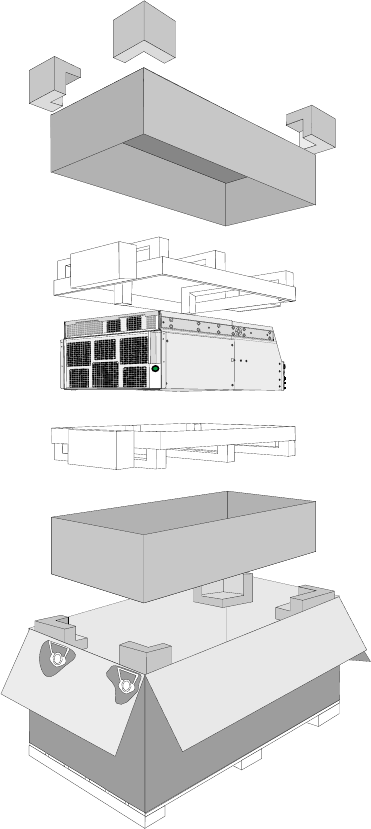
iQ Platform
It is recommended that three people should remove the iQ Platform from its
packing and to mount it in the cabinet to avoid damage to the unit and those
who are unpacking it.
One person should hold the packing still while two people, one either side of
the unit, lift it straight up and out of the packing using the handles provided.
The packing can then be removed from beneath.
☞Caution (CT 1) Disk Drives - This equipment may contain disk drives
which are prone to mechanical shock damage (12/97).
2116-58-030 A Quantel Installation Manual 03 3
Unpacking
03 4 Unpacking 04/01 2116-58-030 A
Unpacking

iQ System
Installation Manual
04 - Racking
2116-58-030 A Quantel Installation Manual 04 1
Racking
04 2 Racking 04/01 2116-58-030 A
Racking
Rack Mounting
Important Information
The cabinets required to house the iQ Platform system are standard 19 inch
(483 mm) as detailed chapter 2 “Preparation”.
This system is delivered with the iQ Platform (8U) and 2 Dylan HD disk
arrays (8U in total) which require 16U of contiguous rack space.
The system is supplied with a rack mounting kit and includes rack slides and
reinforcing plates to be fitted as described in this chapter.
It is strongly recommended that cabinets with extending feet are used to
ensure that the cabinet remains stable during installation and during any
maintenance.
The cabinets should be fitted with units from bottom to top to prevent the
cabinets falling forward.
☛WARNING (WT 1) Heavy or Bulky Equipment - This equipment may be
heavy or have awkward dimensions. Attempting to lift or move the
equipment may cause personal injury if due care and consideration are
not taken. Before attempting, read any unpacking/handling instructions
and always comply with Health & Safety rules. (12/97)
☛WARNING (WI 2) Rack Slides - Never have more than one equipment
unit on extended rack slides as this may cause the cabinet to fall
resulting in personal injury and possible other damage. (12/97)
☞Caution (CT 1) Disk Drives - This equipment may contain disk drives
which are prone to mechanical shock damage. (12/97)
2116-58-030 A Quantel Installation Manual 04 3
Racking
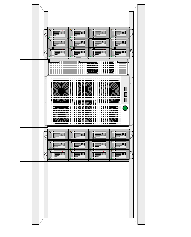
Rack Layout
The system’s units should be mounted as shown.
04 4 Racking 04/01 2116-58-030 A
Racking
8U iQ Platform
Dylan HD
Disk A
Dylan HD
Disk B
4U
4U
IQ Platform Rack Mounting Procedure
The system’s rack mounting kit should be fitted to the cabinet in the following
order.
iLocate and fit the two inner slides to the unit as shown below using 4
off M4 x 12 pan head screws and wavy washers:
2116-58-030 A Quantel Installation Manual 04 5
Racking
Inner Slide
M4x12
Pan Head
Poz Screws
Release Button
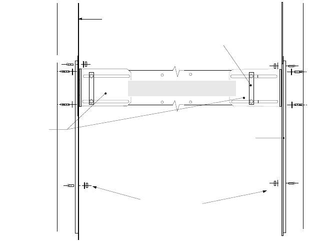
ii Assemble the outer slides as shown below:
iii Locate four identical mounting bars and fix them to the front and rear
of the cabinet using the screws (11-01-3899), washers (10597-126)
and nuts (12-01-0508). Ensure that the screw heads do not protrude
from the mount bar.
iv Fit the relevant outer slide assemblies to the cabinet with the clamp
bars (2047-10-127) using screws (10597-127) and washers
(13-01-0170).
04 6 Racking 04/01 2116-58-030 A
Racking
Slide Mount
Bracket
(2048-16-101)
FRONT
Slide Outer Assembly
(55-02-0582)
Pan Head Poz Screw
(11-01-3899)
Special Washer
(10597-129)
Full Nut
(12-01-0508)
Mount Bar
M5 Wavey Washer
(13-01-0170)
Pan Head Poz Screw
(11-01-1454)
Clamp Bar
(2048-15-102)
Front Mounting
Angle of Cabinet
Special Screw
(10597-127)
Wavey Washer
M5 (13-01-0170)
Note that when fixing the clamp bars, loosely secure them in the first
instance in order that the outer slide assembly may be inserted between
the clamp bar and the cabinet frame before tightening completely.
vBefore proceeding, first lift off the front panel from the unit. These will
be replaced when the loading operation is complete.
2116-58-030 A Quantel Installation Manual 04 7
Racking
SCREW
10597-127
SCREW
10597-127
WASHER WAVEY
13-01-0170
WASHER WAVEY
13-01-0170
MOUNT BAR
CLAMP BAR
2047-10-127
CABINET FRAME
SLIDE
ASSEMBLY
CABINET
FRONT
CABINET
LEFT-HAND
SIDE
vi When fitting the unit into the cabinet, first line up the inner slides at the
rear of the unit (left and right), with the outer slides at the front of the
cabinet. When the inner and outer slides are aligned, begin pushing
the unit gently onto the rack slides.
vii The unit will move onto the rack a short way before the ‘buttons’ on
each side of the unit’s inner slides, will catch against the outer slides
and stop any more movement.
viii To continue loading, hold the buttons down and advance the outer
slides a short way so that the outer slides themselves hold the buttons
down. The unit can now be pushed further onto the rack.
ix The left and right buttons will stop the unit once more before it is fully
loaded into the cabinet. Again, manually hold the buttons down and
gently advance the outer slides a short way so that they press the
buttons down themselves.
xContinue pushing the unit all the way onto the rack slides and so into
the cabinet.
xi Once on the rack slides and in the cabinet, the unit should be secured
to prevent it accidentally being pulled out. The unit can be secured
with the screws (11-01-1454) and washers (13-01-0196). These
screws fit through the front of the unit and into the mount bar.
Note that when the unit is to be pulled out on the rack slides, these
screws are released but should always be secured again when work on
the slides is complete.
xii Once the unit is successfully loaded onto the rack slides and secured
into the cabinet, the front panel of the unit can be replaced.
04 8 Racking 04/01 2116-58-030 A
Racking
Dylan HD Disk Arrays
The Dylan HD disk arrays are rack mounted on the angles provided. .
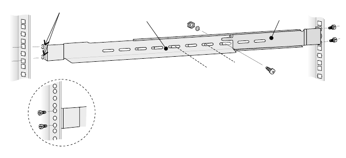
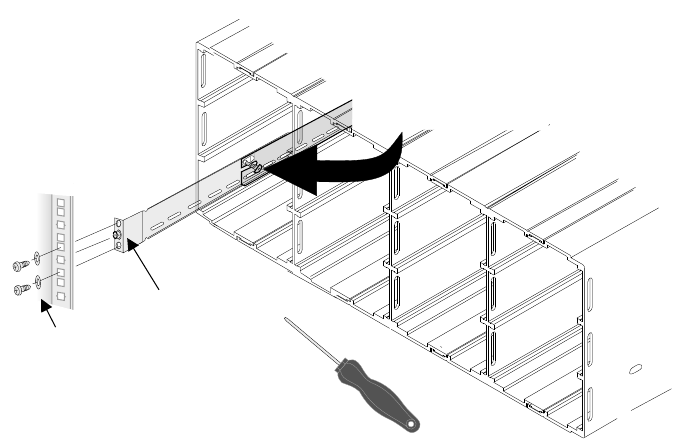
A Fitting the Rails to the Cabinet
The unit must be rack mounted on the angles provided. The unit is 19"
(483mm) wide and can be mounted into most standard 19" cabinets.
iFit 2 locator pins (16931-02) and washers to the end of the left-hand
rail (16889-1). Fit 1 locator pin and washer into the middle hole in the
end of the left-hand support (16891-2)
ii Place the left-hand support behind the left-hand rail and extend the
pair until they are approximately the same length as the distance
between the front and back flanges of the cabinet.
iii Fit3xM5PanHead screws, washers and nuts finger tight to join the
left-hand rail and left-hand support together.
iv Place the location pins (on the front end of the left-hand rail), from the
inside, into the correct square slots in the cabinet front flange. Adjust
the length of the left-hand rail/support assemble so that the locator pin
on the end of the left-hand support fits into the correct square hole on
the inside of the cabinet’s rear flange.
2116-58-030 A Quantel Installation Manual 04 9
Racking
Left-hand Rail (16889-01)
(right-hand 16890-01)
For cabinets with holes instead of square slots,
fit the locator pins from the outside.
Left-hand Support (16891-02)
(right-hand 16892-02)
Locator Pins
vSecure the rear of the assembly to the cabinet rear flange using 2 x
M5 Pan Head screws and washers.
vi Ensuring that the assembly is fitted tightly between the front and rear
cabinet flanges tighten the 3 M5 Pan Head screws joining together the
left-hand rail and support.
vii Repeat for the right-hand side using the right-hand rail (16890-1) and
the right-hand support (16892-2)
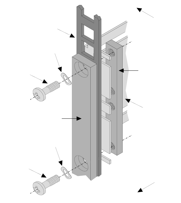
B Securing the Enclosure to the Rails
iSecure Enclosure into rack angles, via the two PSU compartments
using2xM5countersunk screws. These fit into the captive nuts in the
left-hand and right-hand rails.
04 10 Racking 04/01 2116-58-030 A
Racking
Fix M5 countersunk crosshead
screw through enclosure into rail.
Locator Pin
& Washer
M5 Cross head screws
and Washers
C Fitting the PSU Modules
There are two identical Power Supply Modules which are fitted into the left
(bay 1) and right (bay 4) positions at the rear of the enclosure.
☛Warning: Ensure that no mains supply is connected to either PSU
module before attempting to fit the Interface Module.
Hold the latch while pushing the module gently home into the bay, ensure
that it is fully engaged and that the retention latches are engaged into the
enclosure bay. Fit and tighten retaining screw on each PSU module panel.
☛Warning: The screws must be fitted to prevent unauthorised removal
of either PSU module and exposure to energy hazards.
2116-58-030 A Quantel Installation Manual 04 11
Racking
Hole for PSU
retaining screw
LED
Retention Latch
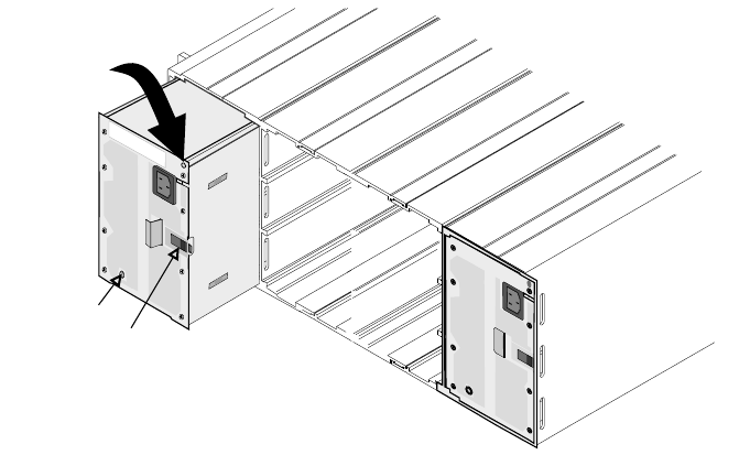
D Fitting the Interface Module
The Interface Module is fitted into the rear of the enclosure between the 2
PSU modules as shown bellow.
Before attempting to fit the Interface Module ensure that all packing has
been removed from around the connectors and that there is no damage to
the connectors.
☛Warning: Ensure that no mains supply is connected to either PSU
module before attempting to fit the Interface Module.
With both hand carefully slide the Interface Module into the enclosure
locating the handle into the guide as shown.
Apply a firm pressure the rear panel of Interface Module until the rear panel
is flush with the PSU Modules already fitted. The use the handle to lock the
Interface Module in position.
04 12 Racking 04/01 2116-58-030 A
Racking

☞Caution: Excessive pressure or misalignment of the module can cause
irreparable damage to the module and the enclosure.
Fit and secure the 4 fixing screws in the 4 corners of the Interface Module’s
back panel.
☛Warning: The screws must be fitted to prevent unauthorised removal
of the Interface module and exposure to energy hazards.
E Fitting the Disk Carriers
☞When delivered the disk drives within the carriers are formatted but
have no nominated position within the enclosure. Once data has been
saved on these disks, however, their position within the enclosure is
critical.
2116-58-030 A Quantel Installation Manual 04 13
Racking
Once the carrier is in place
use the security screwdriver
supplied to lock carrier into
the enclosure.
Push the carrier handle to close.
Release by pressing the small indentation
on the left of the carrier handle.
Push the carrier gently
untill it is stopped by the
camming lever on the right.
iCarefully slide the each disk carrier into an empty compartment in the
enclosure.
ii Push the carrier gently until it is stopped by the camming lever on the
right hand side of the carrier handle.
iii Push the carrier handle on the left-hand side until it clicks in to
position.
iv Secure the carrier in enclosure using the security screw driver
provided. Turning the screwdriver anti-clockwise will lock the carrier
and prevent accidental release of the disk carrier during operation.
04 14 Racking 04/01 2116-58-030 A
Racking
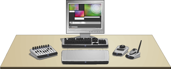
Workstation
Workstation Layout
The workstation consists of a tablet and pen, hand unit (with docking port),
fader panel, jog / shuttle panel and a keyboard as shown below. The
connection between the control system and iQ Platform is via a serial link.
The tablet should be situated away from stray magnetic fields and
electromagnetic interference. The workstation requires a VGA monitor to
display the output of the system, situated in the best position for the
operator.
Mounting the Tablet
The tablet is normally placed on top of the desk but can be mounted flush
with the desk surface if required. There are no fixing points to secure the
tablet to the desk top and therefore desks with steep inclines, or smooth
surfaces should be avoided.
☞Caution: Do not dismantle the tablet or its controller as the delicate
electronics can be easily damaged.
Mounting the Keyboard
The keyboard is normally placed on the desk. There are no fixing points to
secure the keyboard to the desk top and, therefore, desks with steep inclines
or those with smooth surfaces should be avoided.
2116-58-030 A Quantel Installation Manual 04 15
Racking
Mounting the Fader Panel
The fader panel is normally placed on the desk. There are no fixing points to
secure the panel to the desk top and, therefore, desks with steep inclines or
those with smooth surfaces should be avoided.
Mounting the Jog / Shuttle Panel
The jog / shuttle panel is normally placed on the desk. There are no fixing
points to secure the panel to the desk top and, therefore, desks with steep
inclines or those with smooth surfaces should be avoided.
Assembling the Hand Unit / Mounting the Docking Port
☞The hand unit is designed for wired operation. Where the local
environment and regulations permitand where the docking port is
provided it can be used in wireless mode.
☞Note that the docking port can only be supplied where local
regulations permit the use of the specific radio frequency employed by
the Hand Unit and docking port.
A Important Battery Information
☞Please ensure that this information is made available to installers,
users and service personnel.
☞Do not fit batteries in the Hand Unit if the cable is connected.
☛Warning: Do not open or mutilate a battery, dispose of in a fire, expose
to heat above 54°C (130°F), immerse in water, install improperly or
short battery terminals. These actions may cause the battery to
overheat, leak or explode causing burns and personal injury.
☛Warning: Do not solder battery terminals.
☛Warning: Do not store or carry batteries in a way that could lead to the
terminals being short-circuited.
☛Warning: Do not store batteries in a hot or humid place.
04 16 Racking 04/01 2116-58-030 A
Racking

iQ System
Installation Manual
05 - Connection
2116-58-030 A Quantel Installation Manual 05 1
Connection
05 2 Connection 04/01 2116-58-030 A
Connection
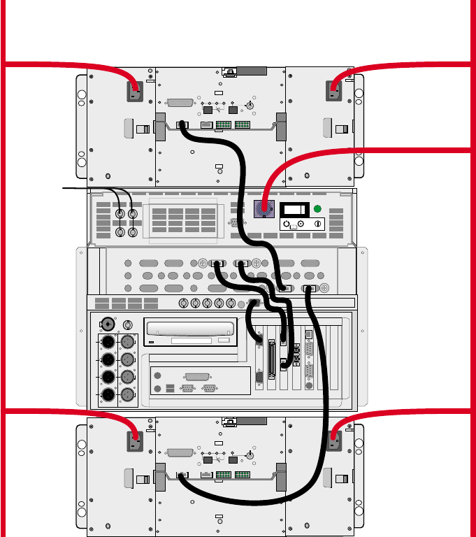
System Connection
System Connection Overview
2116-58-030 A Quantel Installation Manual 05 3
Connection
HD IN
SD IN
HD OUT
SD OUT
HD OUT
SD OUT
SD IN
HD IN
DISK A DISK B
CPU A CPU B
ATTENTION
A
REF IN
B
REF OUT
TX
RX
VGA 1
LINK A
RAID
W/S
VGA 2
LINK B
VTR B
VTR A
KB L
MOUSE
WORD
KBD USB
1
0
PARALLEL
CLOCK
MONITOR
AES/EBU OUTAES/EBU IN
1/2
3/4
5/6
7/8
VIDEO IN 1
Y/G U/B V/R HV
EQ
TEST
HOST SERIAL
SYS FAN
RUN
PWR
MUTE
TEMP STANDBY
TEST
HOST SERIAL
SYS FAN
RUN
PWR
MUTE
TEMP STANDBY
Dylan HD
"Disk A"
Disk A
Dylan HD
"Disk B"
POWER
SOURCE 2
POWER
SOURCE 1
Locking
Reference
Loop
Through
Disk B

Connect From Using Cable To
IQ Platform “VGA 1” IQ Platform “Video In 1”
IQ Platform “CPU A” 31-10-9020 IQ Platform “LINK A”
IQ Platform “CPU B” 31-10-9020 IQ Platform “LINK B”
IQ Platform “Disk A” 31-10-9015 Dylan Disk A “Serial”
IQ Platform “Disk B” 31-10-9015 Dylan Disk B “Serial”
Electrical Supply Considerations
The Dylan HD disk arrays have dual independent electrical supply inputs,
switching and PSUs to provide fault tolerance. It is therefore recommended
that the two separate mains inputs to each unit are supplied from a separate
mains supply spur (of the same phase) to maintain the fault tolerance of the
compete system.
The System Connection schematic shows the left-hand electrical supply
input of each unit connected to supply 1 and the right-hand connected to
supply 2. It is recommended that supply 1 and supply 2 have separate circuit
breakers so if one of the pair is tripped by a fault condition the system will
remain operational.
☛WARNING: BOTH OF THE MAINS ELECTRICAL SUPPLY CONNECTIONS TO EACH
UNIT MUST BE REMOVED TO GIVE COMPLETE ELECTRICAL ISOLATION.
Cabling Considerations
The cable connections to the rear middle panel of the iQ Platform must be
looped and tied back so that the PC Sub-system can be removed for
maintenance purposes.
05 4 Connection 04/01 2116-58-030 A
Connection
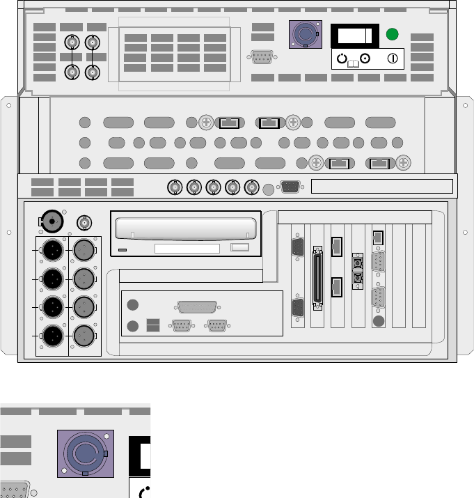
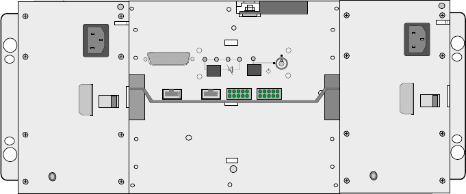
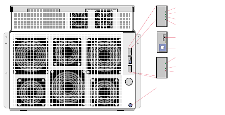
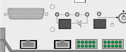
IQ Platform
Rear Panel Layout
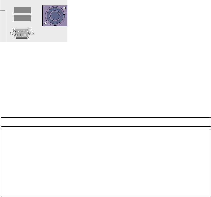
Mains Connection
The iQ Platform’s mains connector and mains
switch/circuit breaker are situated on the rear
panel. The connector is a 20 amp Nuetrik
Powercon NAC3FCA type which is supplied with
a mating cable (21 amp rated, 13 amp fused).
2116-58-030 A Quantel Installation Manual 05 5
Connection
HD IN
SD IN
HD OUT
SD OUT
HD OUT
SD OUT
SD IN
HD IN
DISK A DISK B
CPU A CPU B
ATTENTION
A
REF IN
B
REF OUT
TX
RX
VGA 1
LINK A
RAID
W/S
VGA 2
LINK B
VTR B
VTR A
KB L
MOUSE
WORD
KBD USB
1
0
PARALLEL
CLOCK
MONITOR
AES/EBU OUTAES/EBU IN
1/2
3/4
5/6
7/8
VIDEO IN 1
Y/G U/B V/R HV
EQ
T
ENTION

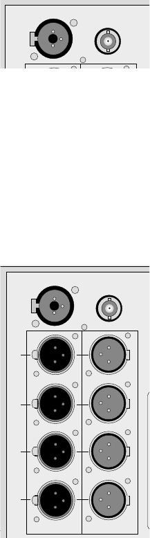
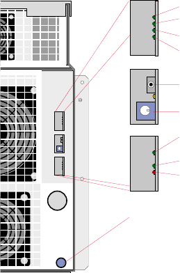
Digital Video Connections
A General
The iQ Platform provides the following digital video connections on the rear
middle panel :
2 x SD (standard video) inputs
2 x SD (standard video) outputs
2 x HD (high definition video) inputs
2 x HD (high definition video) outputs
☞Caution: This equipment provides full broadcast specification video
outputs when connected to a full broadcast specification studio
locking reference. If the system is operated in ‘free run’ mode it cannot
provide the accuracy of line frequency required for full broadcast
specification video output. The ‘free run’ mode should only therefore
be used for setup, configuration and test purposes.
B SD Video Inputs and Outputs
The iQ Platform provides 2 independent SD inputs (”SD IN A” and “SD IN B”)
it also provides 2 independent SD outputs (”SD OUT A” and “SD OUT B”).
These inputs and outputs are assigned within the iQ applications.
These SD bit-serial digital video connections (with embedded audio
conforming to ANSI/SMPTE 272M-A) allow the system to be connected
directly into bit-serial environments and to equipment conforming to ITU-R
BT 606 & 656-2. See iQ Platform Technical Specification for full details.
05 6 Connection 04/01 2116-58-030 A
Connection
IN
HD SD
OUT OUT IN
HD SD HD SD HD SD
When embedded audio is decoded from the input video “Group 1” is used.
When embedded audio is output by the iQ Platform the audio “Group 1” is
be used.
Each embedded audio input must have present one packet of 4 channels of
digital audio (even if it is silent). The audio must be synchronous to 48 kHz.
C HD Video Inputs and Outputs
The iQ Platform provides 2 independent HD inputs (”HD IN A” and “HD IN
B”) it also provides 2 independent SD outputs (”HD OUT A” and “HD OUT
B”). These inputs and outputs are assigned within the iQ applications.
These HD bit-serial digital video connections (with embedded audio
conforming to SMPTE 299M) allow the system to be connected directly into
bit-serial environments and to equipment conforming to SMPTE 274M,
SMPTE 292M, SMPTE 295M and SMPTE 296M. See iQ Platform Technical
Specification for full details.
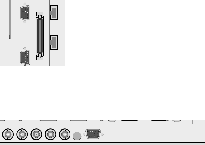
Serial Control Connections
A General
The system provides a dedicated workstation
control connection (”W/S”) and 2 VTR control
connections on the rear panel.
For the workstation a shielded RJ-45 connector is
used and for the VTR connections two 9-way
D-subminiature female (DE-9S) with metric (M3)
female screw-lock are used with the following
signal connections.
2116-58-030 A Quantel Installation Manual 05 7
Connection
TX
RX
LINK A
W/S
LINK B
VTR B
VTR A
KB L
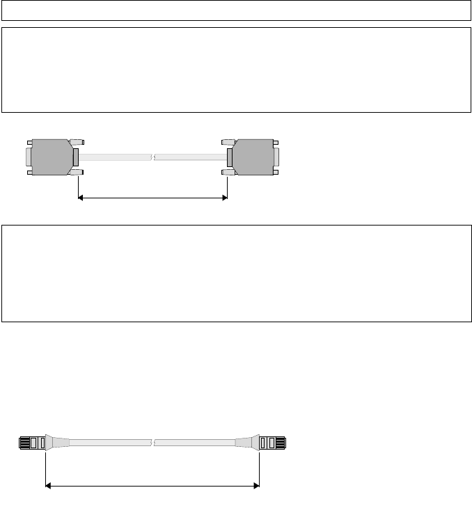
B VCR Connections
The VCR connectors have the following pin-outs.
Pin Function Pin Function
1 *Chassis Gnd 6 0 V
2 Receive - 7 *Receive +
3 *Transmit + 8 Transmit -
4 0 V Transmit 9
5
A10 metre VTR control
cable is provided. This
is a screened 6-core (3
x twisted pair) cable
with the following
connections.
9-way Male 9-way Male
Pin 2 Receive - (red) Pin 2
Pin 7 Receive + (white) Pin 7
Pin 3 Transmit + (brown) Pin 3
Pin 8 Transmit - (white) Pin 8
Pin 9 Ground (b/w) Pin 9
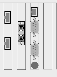
C Workstation Connection
This serial connection is designated for use by the workstation and connects
to the “W/S” socket on the Control interface box.
A10 metre workstation
control cable is
provided. This is a
shielded 8-core cable
which has pin to pin
connections.
SCSI Port
The iQ Platform provides a SCSI port for test purposes only.
05 8 Connection 04/01 2116-58-030 A
Connection
2.00 m
10.00 m
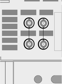
Locking References
The iQ Platform uses input reference (obtained
from the selected input video source) and 2
output locking references (A for Standard video
and B for HD video to match the video standard
to be output by the system).
The SD reference input “A” allows the iQ Platform
to accept an analogue reference signal
conforming to ITU-R BT 601 & 656-2 and lock the
system’s output to this standard.
This HD reference input “B” input allows the iQ
Platform to accept an analogue video reference
signal conforming to SMPTE 274M and lock the
system’s output to this standard.
2116-58-030 A Quantel Installation Manual 05 9
Connection
A
REF IN
B
REF OUT
SVGA Monitor Output
The platform provides 2 standard VGA monitor
outputs. The “VGA 1” output is connected
directly to the local workstation monitor (or to a
remote workstation monitor via the video
equaliser). The “VGA 2” output is for secondary
output and diagnostics purposes.
On platforms that include a Video Equaliser (for installations where the
Workstation is to be located away from the platform) a monitor quality
standard SVGA output is provided via 5 BNC connections. These BNC
outputs are connected to the SVGA workstation monitor. On platforms fitted
with the Video Equaliser the “VGA 1” connection is connected directly to the
“Video In 1” connection using a short cable.
The Video Equaliser has 3 settings which are made using the rotary switch
on the panel:
0 - cable lengths from 0 to 15m
1 - cable lengths from 15m to 50m
2 - cable lengths from 50m to 100m
Note that the 5 cables must be same length and of the same cable type to
ensure that the video image that appears on the Workstation monitor is not
distorted.
05 10 Connection 04/01 2116-58-030 A
Connection
SD IN
HD OUT
SD OUT
HD OUT
SD OUT
SD IN
HD IN
VIDEO IN 1
Y/G U/B V/R HV
EQ
TXRX
VGA 1
LINK A
RAID
VGA 2
LINK B
Analogue Audio Monitor
This combination socket provides both an
analogue audio monitor output via an audio jack
socket and an AES/EBU audio monitor output via
the 3-pin XLR socket.
The analogue audio is a high impedance connection with a minimum load of
15kΩused for diagnostic output only. This output is not clean and should
not be used as an analogue output device.
☛Warning: If headphones are used on this output an approved audio
limiter must be used.
The 3-pin XLR audio connector provide a twin-channel digital AES/EBU 48
kHz audio outputs.
Digital Audio Connections
AES/EBU Inputs: the four 3-pin XLR audio
connectors allow the are iQ Platform to accept
four twin-channel (stereo) digital AES/EBU 48
kHz audio inputs.
The system must be provided with synchronous
digital audio, ie; the audio sample rate must be
synchronised to the video reference signal that
the system is receiving, as set out in the
AES/EBU standard.
AES/EBU Outputs: The four 3-pin XLR audio
connectors provide the iQ Platform’s four
twin-channel digital AES/EBU 48 kHz audio
outputs.
Word Clock Output:: This is the 48 kHz word
clock output used to lock an external analogue to
digital converter.
2116-58-030 A Quantel Installation Manual 05 11
Connection
WORD
CLOCK
MONITOR
AES/EBU OUTAES/EBU IN
1/2
3/4
5/6
7/8
WORD
CLOCK
MONITOR
Fibre Optic Connection
A Description
A standard SC duplex fibre optic connection is
provided on the rear panel of the iQ Platform for
1000base-SX Gigabit Ethernet. This is used to
connect the iQ Platform into a Clipnet network of
Quantel and 3rd party products via 62.5/125 µm
(or 50µm) fibre optic cabling. A connection can be
made directly to another unit or via a HUB.
Clipnet is implemented using Gigabit Ethernet as a network carrier, with
TCP/IP as a low level network protocol, and the Quantel Clipnet Protocol
(QCP) as a high level protocol.
B Important Information
The Modules contain a class 1 laser product. Although the standard EN
60950 does not require a warning to be made, avoid eye contact with the
beam emitted and follow any special instructions given by the manufacturer
when attending to the devices.
C Connection
Do not remove dust cover until immediately prior to installation.
Clean the connector as detailed in the Maintenance chapter.
To insert the connector hold the connector by the strain relief boot directly
behind the connector housing.
Insert the connector into the socket in the correct orientation so that keys in
the connector and socket match and both latching arms ‘click’ into place.
D Disconnection
Grasp the connector housing and disconnect the housing from the unit.
Cover connector ends with clean dust caps when not in use.
05 12 Connection 04/01 2116-58-030 A
Connection
TX
RX
LIN
K
RAID
LINK B
VTR B
RA
Attention Connection
A Description
The “Attention” port on the rear panel of the iQ
Platform provides a remote monitoring facility that
can be used to raise an alarm if a fault condition
occurs. This connection should be used to inform
the installation engineer that the machine
requires attention.
Connections to a change over relay are provided with a fused +5V supply
and 0V.
If a ‘loop back’ connector (Pin 7 connected to Pin 9, Pin 3 to Pin 5) is
installed here, then an alarm device inside the crate will sound when
attention is required.
Alternatively, an equivalent device or indicator can be connected externally
and situated in a suitable ‘Engineering’ location.
Pin Function Pin Function
1 0 V, Relay 6 0 V
common 7 +5V, Internal
2 buzzer
3 Fused +5V 8 Fused +5V
Supply Supply
4 Relay normally 9 Relay common
open
5 Relay normally
closed
Note (1): The relay rating is 0.25 A.
Note (2): Relay state for attention is ‘Normal’.
This means that, for an externally wired circuit, the relay of a machine that is
powered off will be in the ‘attention’ state, but the +5V supply from it will be
off. Therefore, if positive indication of a powered off machine is required, an
external power supply will be necessary.
2116-58-030 A Quantel Installation Manual 05 13
Connection
ATTENTION
05 14 Connection 04/01 2116-58-030 A
Connection
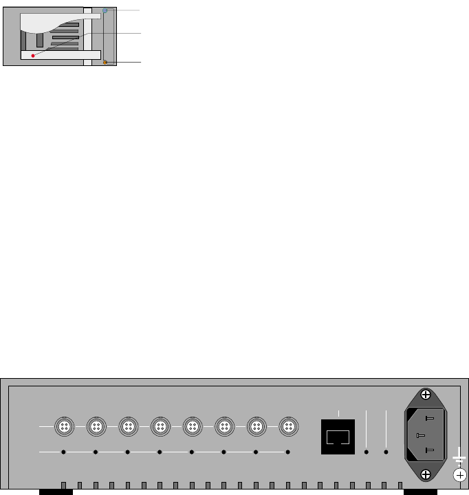
Dylan HD
Back Panel Details
Mains Connection
The two independent power supply modules require individual Mains
connections.
☞Caution: The PSU Modules are not auto-ranging, therefore failure to
select the correct range will damage the modules.
☞Caution: When the Dylan HD is shipped to certain countries an
additional Electrical Supply Filter unit is provided to comply with
applicable standards in those countries. When this filter unit is
supplied it must be used.
Host Connection
The “Host” socket on the rear of the Interface panel is connected to the iQ
Platform as detailed in the “System Connection” section.
2116-58-030 A Quantel Installation Manual 05 15
Connection
TEST
HOST SERIAL
SYS FAN
RUN
PWR
MUTE
TEMP STANDBY
05 16 Connection 04/01 2116-58-030 A
Connection
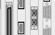
Workstation
Inter-connection
The Control Interface box is connected to the iQ Platform “W/S” socket
(RJ-45) and the Control Interface box “M/F” socket (RJ-45) using the serial
cable provided.
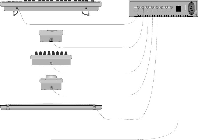
The components of the Workstation are connected to the Control interface
box as shown:
All Workstation units connect to the Control Interface box using identical
leads provided and can be plugged into any of the “W/S” sockets.
☞Note that if the docking port is not provided a cable must be fitted
directly between the Hand Unit and the Control Interface unit.
2116-58-030 A Quantel Installation Manual 05 17
Connection
M/F
O/L
OK
O/L W/S
Keyboard
Hand Unit / Docking Port
Fader Panel
Jog/Shuttle Panel
Tablet
iQ Platform "W/S"
05 18 Connection 04/01 2116-58-030 A
Connection

iQ System
Installation Manual
06 - Start-up
2116-58-030 A Quantel Installation Manual 06 1
Start-up
06 2 Start-up 04/01 2116-58-030 A
Start-up
Startup & Shutdown Procedures
IQ Platform
The iQ Platform contains 2 separate
power supply units. One for the
Image Processor unit (in the front
compartment) and the other for the
PC sub-system (in the rear
compartment). These are turned on
using the switches on the rear top
panel of the unit.
The system is designed to be powered and operating continually. However,
when the system is to be powered-down and powered-up, the following
should be remembered.
A Initial Start-up
Before attempting to power-up the system for the first time, ensure that it has
the correct mains supply and that the system’s components are correctly
connected together.
B Normal Start-up
Always ensure that the control station components are turned on before the
iQ Platform is turned on or reset.
1. Install power connector. This supplies power to the
ATX PSU (in the PC sub-system) and activates the ATX
standby DC O/P supplying power to the rear panel
illumination LED's. Note that the front panel LED will
show Red as power is connected.
2. Switch on the breaker. This activates the standby
mode of the Image Processor unit PSU. Note that the
front panel LED will show Red.
3. Press the green button. This is the remote power
on/off switch and turns on the ATX PSU to supply power
to the PC sub-system and turns on the Image Processor
PSU to power to the Image Processor unit the unit’s fans.
Note that the front panel LED will flash red during system
startup then turn solid blue when the iQ program is
running to indicate that the system is ready for use.
2116-58-030 A Quantel Installation Manual 06 3
Start-up

Note that from power up the windows operating system takes approximately
1 minute to boot up then the system is available for use.
C Power-down Procedure
Always ensure that any graphics items have been saved.
1. Shut down the iQ operating system.
2. Press and hold the green button for five seconds, this
remotely turns off all main outputs returning both PSU's
to Standby.
3. Switch off the breaker, this turns off the Image
Processor PSU. At this point the rear panel illumination
LED's are still on.
4. Remove power connector.
Note that if the breaker is switched off before the ATX PSU main output,
then the PC sub-system remains powered and operating. Only the Image
Processor unit is powered down. To re-apply power to the Image Processor
unit, simply turn on the breaker.
06 4 Start-up 04/01 2116-58-030 A
Start-up
Sh t Down...u
Dylan HD
A Initial Start-up
Before attempting to power-up the system for the first time, ensure that it has
the correct mains supply and that the system is correctly connected together.
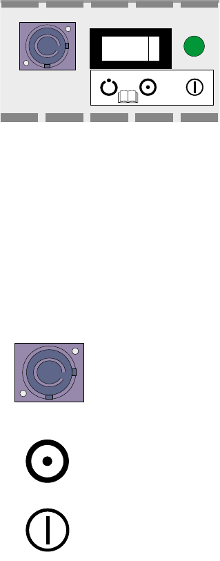
B Normal Start-up
The unit can be set to either enable or disable user power on and off. This is
done using the lockable switch on the Interface panel on the rear of the unit.
If this switch is in the “Run” position the unit will be powered up and run
continuously. If the switch is in the “Standby” position the black button under
the “standby” LED will power up and run the unit. This button must be held
for several seconds until the unit powers-up.
Note that the “standby” LED when lit indicates that there is power connected
to at least one of the PSU modules.
Always ensure that all externally connected disk drives are turned on before
the iQ Platform is turned on or reset.
C Power-Down Procedure
The system is designed to be powered-up and operating continually.
However, when the system is to be powered-down and then powered-up,
the following should be remembered.
If the lockable switch is in the “Run” position it should be moved to the
“Standby” position then pressing the black button under the “standby” LED
for several seconds will run-down the disks then power-down the unit.
2116-58-030 A Quantel Installation Manual 06 5
Start-up
System Reset
The system can be
reset by using the
system’s reset button
(inside the front panel
and accessed through
the hole in the front of
the unit.
Resetting will reboot the
system operating
software after a few
minutes. From power
down it takes longer.
06 6 Start-up 04/01 2116-58-030 A
Start-up
Blue - System OK
Blue Flashing - PC Sleep
Red - Standby
Red Flashing - Fault
System Reset
S/W Boot Address
+12 Volt Rail ok
-5 Volt Rail ok
+5 Volt Rail ok
+3.3 Volt Rail ok
Green-PC Poweron
Flashing - PC Sleep
Green - CPU Happy
Red - CPU Unhappy
System Status
Correct Operation
There are various indications that the system’s individual units are operating
correctly. These can give a quick indication of the system status if there
appears to be a failure.
IQ Platform
The status of the iQ
Platform itself can be
determined by the
diagnostics LEDs
behind the front panel
and via remotely via the
“Attention” port on the
rear of the unit.
The light in the bottom right-hand corned of the panel indicates the current
status of the iQ Platform:
Solid Blue System Happy (ie the unit is powered up and running
correctly).
Flashing Blue PC Sleep Mode (ie the unit is powered up and
operational but the PC sub-system has entered on of its
power saving sleep modes). Sleep mode is automatically
instigated if the PC sub-system has not been used for a
period of time.
Solid Red Standby Mode (ie the Mains is connected to the platform
but the unit’s PSU are not yet operational). A solid red
can indicate that the rear panel Mains switch (breaker) in
not in the correct position or that a PSU unit has failed.
2116-58-030 A Quantel Installation Manual 06 7
Start-up
Blue - System OK
Blue Flashing - PC Sleep
Red - Standby
Red Flashing - Fault
System Reset
S/W Boot Address
+12 Volt Rail ok
-5 Volt Rail ok
+5 Volt Rail ok
+3.3 Volt Rail ok
Green-PC Poweron
Flashing - PC Sleep
Green - CPU Happy
Red - CPU Unhappy
Flashing Red Fault Condition (ie a fan has failed in the unit or the
system has exceeded its normal operating temperature.
The four LEDs visible through top hole the on the right-hand side of the front
panel indicate that all four power rails are present.
The three LEDs visible through the bottom hole on the right-hand side of the
front panel indicate the following:
Top Green On - PC Powered up
Top Green Flashing - PC Sleep Mode
Middle Green On - CPU Happy
Bottom Red On - CPU Unhappy
06 8 Start-up 04/01 2116-58-030 A
Start-up
Dylan HD Status Checks
A Interface Panel
The LEDs on the
Interface panel, at the
rear of the unit, indicate
the current operational
state of the Unit
(excluding the disk
carriers). Normal
operation is indicated
by all LEDs being
green.
SYS This LED when amber indicates that the unit’s
diagnostics have found an unexpected fault condition.
FAN This LED when amber indicates that there is a fan fail (or
fan stall) condition in one of the two PSU modules. The
amber LED one of the PSU modules identifies which one
is faulty.
PWR This LED when amber indicates that there is a power
failure in one of the two PSU modules. The amber LED
one of the PSU modules identifies which one is faulty. If
the power is turned off to one unit or the power cable is
disconnected it will be indicated in this way.
TEMP This LED when amber indicates that the unit has
exceeded its safe operating temperature.
The 20 green LEDs indicate the activity/status of the disk drives. After the
system has successfully run up should one or more of the disk LEDs
(0,1,2,3,4,5) be lit continuously this indicates a fault.
Under most fault conditions the unit will remain operable until the fault can
be cleared or remedial action taken. If any fault condition is detected the unit
will sound an alarm. This can be muted by holding down the “Mute” button
on the Interface panel. The fault condition will remain as indicated by the
amber LED (or LEDs).
2116-58-030 A Quantel Installation Manual 06 9
Start-up
TEST
HOST SERIAL
SYS FAN
RU
N
PWR
MUTE
TEMP STANDBY
B Disk Carriers
The two LEDs on each
disk carrier indicate its
current status.
When the unit is switched on both the blue and amber LEDs will be lit in all
12 disk carriers. Once each individual disk has run-up the amber LED will
turn off and the blue LED should be lit to indicate that the disk is running
normally.
During operation the blue LEDs will turn off briefly to indicate disk access.
The harder the disks are working the more the blue LEDs will be off. If an
amber LED appear on any disk carrier this indicates a fault condition.
Workstation
A Control Interface Box
The green “OK” LED on the Control Interface box should be lit when the unit
is connected to the Mains electrical supply to indicate the PSU within the box
is operating.
The red “O/L” (overload) LEDs should all be off. If any are lit this indicates
that the is a fault condition with the channel or with the unit connected to it.
06 10 Start-up 04/01 2116-58-030 A
Start-up
M/F
O/L
OK
O/L W/S
Blue LED Disk OK
Security Lock
Amber LED Disk Not Ready
B Tablet
The LED on the tablet should be lit when the pen is in proximity to the tablet
surface. This indicates that the tablet is powered-up and operating correctly.
C Fader Panel
The Quantel Log on this unit should be illuminated. This indicates that the
unit is powered-up.
D Jog / Shuttle Panel
The Quantel Log on this unit should be illuminated. This indicates that the
unit is powered-up.
E Keyboard
The Quantel Log on this unit should be illuminated. This indicates that the
unit is powered-up.
F Hand Unit / Docking Port
The Quantel Log on the docking port (if supplied) should be illuminated.
This indicates that the unit is powered-up.
2116-58-030 A Quantel Installation Manual 06 11
Start-up
06 12 Start-up 04/01 2116-58-030 A
Start-up

iQ System
Installation Manual
07 - Maintenance
2116-58-030 A Quantel Installation Manual 07 1
Maintenance
07 2 Maintenance 04/01 2116-58-030 A
Maintenance
Routine Maintenance
Workstation
A Tablet Care
The tablet itself is made of an expanded foam moulding. The combination of
different plastics and paints used in the production of the tablet restricts the
use of cleaning agents that can be used to ones that are alcohol based.
As with any cleaning substances test that no damage is caused to the plastic
and metal surfaces by applying the cleaning agent to an unobtrusive part
first.
Never clean the tablet using abrasive materials.
☛WARNING (WM 4) Cleaning - Always isolate the equipment from the
electrical supply before cleaning it, especially when using liquid
cleaners. Refer to procedures in the Installation and Technical manual
where supplied. Take note of the types of cleaner that may or may not
be used. (12/97)
B Pen Care
The pressure sensitive pen used with the control station is a delicate device,
and therefore great care must be taken to avoid damage when it is being
used or when it is stored. The following guide lines should be remembered
so that the full operational life of the pen can be ensured:
iDo not attempt to take the pen apart, as this will permanently damage
the pen.
ii The only user adjustment on the pen is replacing the nib. (See next
section).
iii Avoid using excessive pressure when using the pen as this will stress
the pen and increase wear on the tablet surface.
iv Avoid heavy tapping of the pen on the tablet or any hard surface as
this will cause damage to the delicate moving parts inside the pen.
vWhen the pen is not in use for long periods, the pen should be stored
away from areas of strong light as this may cause the plastic to
deteriorate and become brittle.
2116-58-030 A Quantel Installation Manual 07 3
Maintenance
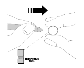
C Changing the Pen Nib
The pen nib, when worn-out can be
replaced with one of the spare nibs
supplied. To do this the nib extractor,
also supplied with the pen, should be
used as shown.
Grip the pen nib with the extraction
tool and pull, firmly, in the direction
shown by the arrow.
The new pen nib can be inserted and gently pressed into place.
Fibre Optic Connections
The fibre optic transceivers used by this equipment are precision devices
and therefore care should be taken to extend their life and provide a reliable
connection at all times.
Before inserting a fibre optic ferrule into its socket follow these instructions.
•Always use a lint-free, isopropyl alcohol dampened cloth to thoroughly
wipe the side and end of the ferrule.
•Blow dry ferrule with clean compressed air.
•Visually inspect the ferrule for lint.
•After every de-mating cycle, clean and blow-dry the ferrule before
re-mating.
•Do not interchange connectors from one unit to another unit without
first cleaning the connector. Otherwise, ti may cause transferring of
small particles, which may cause damage to the device.
•If a problem persists, clean the inside of the precision bore by gently
rotating a lint-free swab with alcohol.
07 4 Maintenance 04/01 2116-58-030 A
Maintenance

Corrective Maintenance
Important User Information
☛Warning: Unqualified personnel must not remove any panels or
modules from the enclosure as this will expose energy hazards.
Disk carriers have been provided with security locking systems
specifically designed to prevent access to non Service Personnel.
Information for Service Personnel
☛Warning the information contained in this section is for qualified
Service Personnel only.
WARNING: Read the Important Product
Information book before use.
A security screwdriver is provided to lock and unlock the disk carriers
to prevent access non Service Personnel. This MUST BE USED.
☛Warning: Removing any of the modules with the mains supplies
connected will expose energy hazzards. Disconnect the Mains
electrical from both PSU modules for complete insolation.
iQ Platform Configuration
The internal hardware configuration of the iQ Platform is factory preset. All
user configuration and setup is made using the Configure application.
The printed circuit boards within the system are configured both physically
(by links and switches) and by software control from the operating system.
Any links and switches are factory set for correct operation, therefore this
section should be considered as reference information only.
A Links and Switches
Any hardware links or switches on the printed circuit boards are used for
local configuration of the printed circuit boards themselves and to configure
the appropriate board addresses so that the operating systems can be
correctly booted and in turn correctly initialise the printed circuit boards.
2116-58-030 A Quantel Installation Manual 07 5
Maintenance
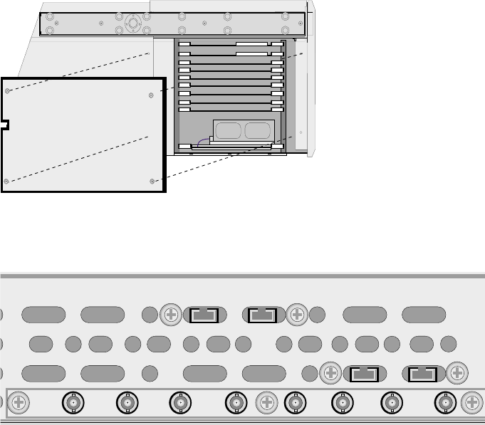
B Image Processor Unit Board Locations
The hardware configuration of the system is factory pre-set. The printed
circuit boards for the Image Processor unit are located behind the left-hand
side panel of the iQ Platform.
2099-81-005 CPU
Link64
2099-76-005 Disk IF
2116-76-005 Vid IO
2116-75-005 Picstore
2116-66-005 PC Disks
☞Caution: All boards (except the Pic Store and the PC disk) cannot be
removed from the board frame until the retaining screws on the
connector panels are removed from the rear panel of the unit.
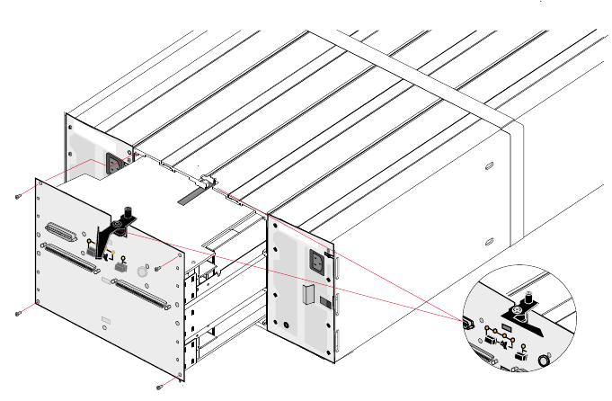
C PC Sub-system
The PC sub-system is mounted on a tray which fits into the rear of the iQ
Platform.
07 6 Maintenance 04/01 2116-58-030 A
Maintenance
HD IN
SD IN
HD OUT
SD OUT
HD OUT
SD OUT
SD IN
HD IN
DISK A DISK B
CPU A CPU B
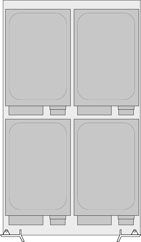
D Carrier Assembly
2116-58-030 A Quantel Installation Manual 07 7
Maintenance
Disk 1 - System
Disk 3 - Audio
Disk 2 - Audio
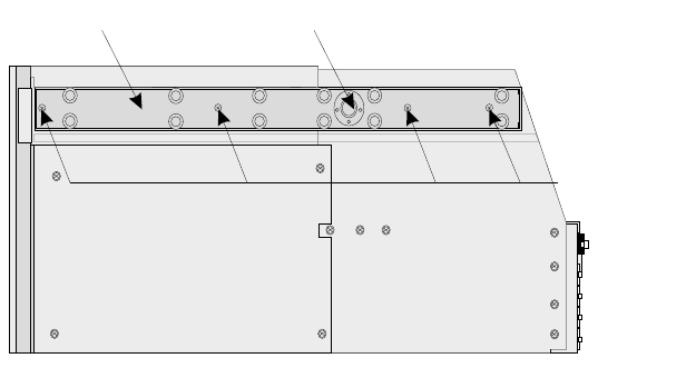
Disk 0 - System
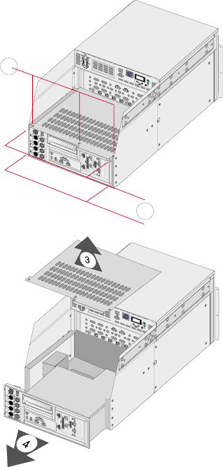
Removing the PC Sub-system
Remove the mains connector.
Remove connections to the PC rear panel.
Remove the screws from the PC
rear panel and PC top panel as
shown in the diagram.
Keep the screws safe as they will be
needed later.
Remove the PC top panel and slide
out the PC tray as shown in the
diagram.
07 8 Maintenance 04/01 2116-58-030 A
Maintenance
1
2
Hot Changing a Dylan HD PSU Module
There are two identical power supply modules fitted in the rear of the
enclosure. The fans within these units are independent of the actual module
and the fans in both PSU modules will remain operational even if one PSU
module fails.
If the PSU module or its fans fail the module should be left in place until a
replacement is available. The unit must not be run without both PSU
modules fitted.
☛Warning energy hazards are exposed if either PSU Module is removed.
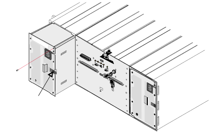
A Removing a PSU Module with the Power On
Once a replacement
unit is available the
faulty unit can be
removed from the
enclosure.
iRemove the mains cable from the PSU unit.
ii Unscrew and remove the single retaining screw.
iii Press the retention latch to the left and pull the module out of the
enclosure using the handle.
iv Carefully remove the PSU Module form the enclosure and place
carefully in a safe place.
2116-58-030 A Quantel Installation Manual 07 9
Maintenance
PSU
Retaining
Screw
Retention Latch
B Fitting a PSU Module with the Power On
Carefully slide the PSU Module into the enclosure until the retention latch
clicks into place then secure using the single screw as shown in the diagram
above.
☞Caution: Ensure that the connector is not damaged during handling
and is free from any contamination (such as packing material).
Hot Changing a Dylan HD Disk Carrier
The unit contains 12 identical disk carriers which contain both data and
parity information. Once the unit has been used to store data the position of
the disk carriers in the enclosure must not be changed otherwise the data
and parity information will become corrupt.
If a single disk carrier becomes faulty (indicated by its amber LED being lit
continuously) it can be changed while the unit is running with a replacement
disk carrier. When a new disk carrier is installed the unit will recreate the
correct data on that disk using the data and parity information from the other
11 disk carriers.
If more than 1 disk carrier indicates a fault advise should be obtained and
under no circumstances should a disk carrier be changed without instruction
from Quantel. A multiple disk fault may indicate an underlying problem that
can be solved without replacing disk carriers.
☞Caution: Changing more than 1 disk at a time will cause permanent and
irreparable data corruption.
07 10 Maintenance 04/01 2116-58-030 A
Maintenance
A Disk Locks
Each disk carrier is
locked in position using
a security screwdriver
to prevent uncontrolled
removal and unwanted
access by unauthorised
or unqualified
personnel.
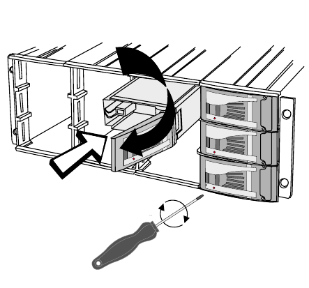
B Removing a Disk Carrier
A disk carrier can be removed from the enclosure while the unit is
powered-up and running:
iUsing the security screwdriver provided unlock the front latch on the
disk to be removed. Turning the screwdriver clockwise will unlock the
disk carrier.
ii Press the handle at the left-hand side until it clicks open.
iii Carefully pull the disk carrier from the enclosure using the handle and
put in a safe place.
C Fitting a Disk Carrier
☞Caution: Ensure that the connector is not damaged during handling
and is free from any contamination (such as packing material).
2116-58-030 A Quantel Installation Manual 07 11
Maintenance
Once the carrier is in place
use the security screwdriver
supplied to lock carrier into
the enclosure.
Push the carrier handle to close.
Release by pressing the small indentation
on the left of the carrier handle.
Push the carrier gently
untill it is stopped by the
camming lever on the right.
07 12 Maintenance 04/01 2116-58-030 A
Maintenance
Index
Air Flow 2-5
Attention Connection
iQ Platform 5-13
Configuration
Carrier Assembly 7-7
Links and Switches 7-5
Connection
Workstation 5-17
Control Interface Box
Dimensions 1-10
Dimensions
Control Interface Box 1-10
Docking Unit 1-9
Fader Panel 1-11
Hand Unit 1-9
iQ Platform 1-5
Jog / Shuttle Panel 1-12
Keyboard 1-8
Tablet 1-7
Docking Unit
Dimensions 1-9
Dylan HD
Mains Connection 5-15
Electrical Supply 2-7
Quality 2-8
Environment
Operating 2-9
Shipment & Storage 2-10
Equipment Location 2-3
Fader Panel
Dimensions 1-11
Fibre Optic Connection
iQ Platform 5-12
Hand Unit
Dimensions 1-9
iQ Platform
Analogue Audio Monitor 5-11
Attention Connection 5-13
Digital Audio Connections 5-11
Digital Video Connections 5-6
Dimensions 1-5
Fibre Optic Connection 5-12
Locking References 5-9
Mains Connection 5-5
Rear Panel 5-5
SCSI Expansion Port 5-8
Serial Control Connections 5-7
System Monitor Output 5-10
Jog / Shuttle Panel
Dimensions 1-12
Keyboard
Dimensions 1-8
Mains Connection
iQ Platform 5-5
Mains Connection
Dylan HD 5-15
Maintenance
Pen 7-3
Tablet 7-3
Workstation 7-3
Operating Environment 2-9
Overview
System Components 1-3
Workstation 1-3
Power-down 6-4
Power-Down 6-5
Racking 4-3
Procedure 4-5
Rear Panel
iQ Platform 5-5
Reset 6-6
Shipment & Storage Environment 2-10
Start-up 6-3
Initial Start-up 6-3
Normal Start-up 6-3
System
Reset 6-6
System Components
Overview 1-3
System Status
iQ Platform 6-7
Workstation 6-10
Tablet
Dimensions 1-7
Unpacking 3-3
iQ Platform 3-3
Workstation
Connection 5-17
2116-58-030 A Quantel Installation Manual 1
Index
2 Index 04/01 2116-58-030 A
Index