Qcom Technology LR802UKN 802.11 b/g/n Wireless USB module User Manual FMIx User Manual MED
Qcom Technology Inc. 802.11 b/g/n Wireless USB module FMIx User Manual MED
UserManual.wiki
>
Qcom Technology
>
LR802UKN User Manual
>
User Manual
Contents
1.
Manual
2.
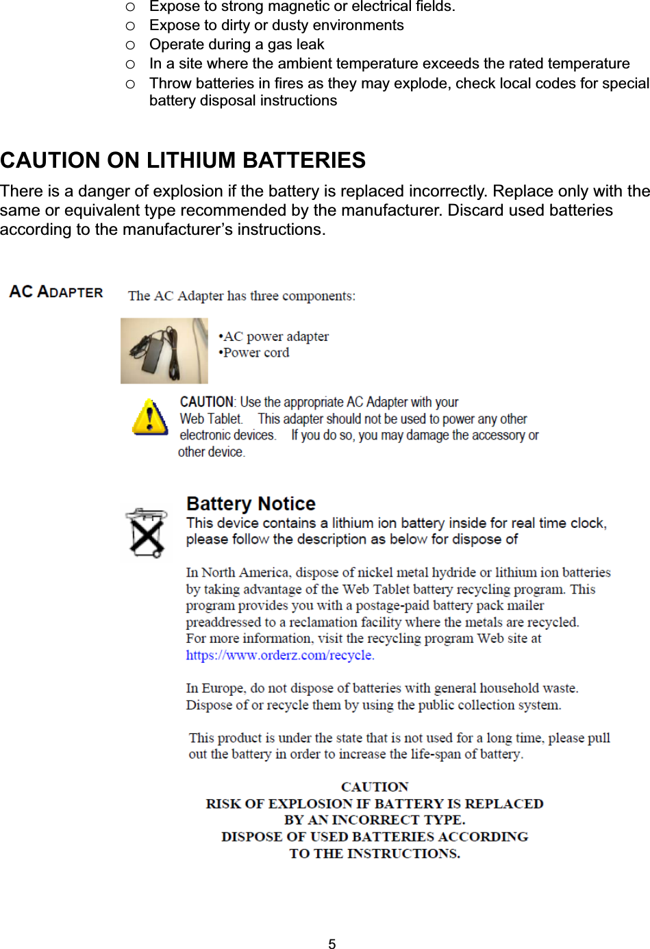
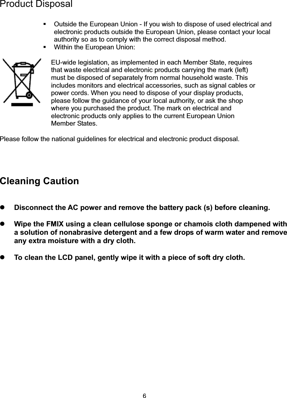
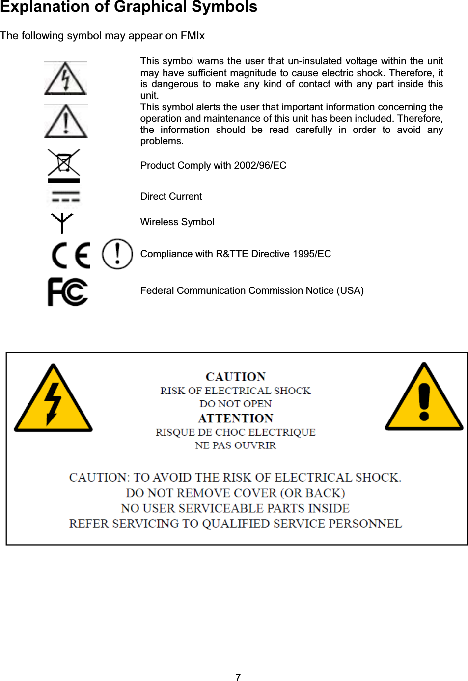
User Manual
User Manual
Navigation menu
Upload a User Manual
Namespaces
Wiki Guide
HTML
PDF
Info
Views
User Manual
Discussion / Help
Navigation