Qcom Technology LR802UKN 802.11 b/g/n Wireless USB module User Manual FMIx User Manual MED
Qcom Technology Inc. 802.11 b/g/n Wireless USB module FMIx User Manual MED
Contents
- 1. Manual
- 2. User Manual
User Manual

FMIx User Manual
2010 August V1.0c
2
Copyright 2010 August
All Rights Reserved
Manual Version 1.0c
The information contained in this document is subject to change without notice.
We make no warranty of any kind with regard to this material, including, but not limited to,
the implied warranties of merchantability and fitness for a particular purpose. We shall not
be liable for errors contained herein or for incidental or consequential damages in
connection with the furnishing, performance, or use of this material.
This document contains proprietary information that is protected by copyright. All rights are
reserved. No part of this document may be photocopied, reproduced or translated to
another language without the prior written consent of the manufacturer.
TRADEMARK
Intel®, Pentium® and MMX are registered trademarks of Intel® Corporation. Microsoft®
and Windows® are registered trademarks of Microsoft Corporation.

3
International Standard Compliance
Safety
Authentication sign of Standard Ispe3ction Bureau for U.S.A. Complies with UL 60601-1
and CAN/CSA C22.2 NO. 601.1
CE MARK
This device complies with the requirements of the EEC directive 89/336/EEC
with regard to “Electromagnetic compatibility” and 73/23/EEC “Low Voltage
Directive”.
FCC
This device complies with part 15 of the FCC rules. Operation is subject to the following
two conditions:
(1) This device may not cause harmful interference.
(2) This device must accept any interference received, including interference that
may cause undesired operation.

4
Safety Precautions
General Safety Precautions
Please ensure the following safety precautions are adhered to at all times.
Follow the electrostatic precautions outlined below whenever the FMIx is
opened.
Do not apply voltage levels that exceed the specified voltage range. Doing
so may cause fire and/or an electrical shock.
Electric shocks can occur if the FMIx chassis is opened when the FMIx is
running.
Do not drop or insert any objects into the ventilation openings of the FMIx.
If considerable amounts of dust, water, or fluids enter the FMIx, turn off the
power supply immediately, unplug the power cord and battery pack, and contact
the FMIx vendor.
To prevent the risk of electric shock, make sure power cord is unplugged from
wall socket. To fully disengage the power to the unit, please disconnect the
power cord from the ac outlet.
Grounding reliability can only be achieved when the equipment is connected to
an equivalent receptacle marked “Hospital Only” or “Hospital Grade”.
The signal input parts or signal output parts (SIP/SOP) need to be connected
properly and any unused SIP/SOP shall not be accessible to unqualified
personnel after the LCD is integrated into a medical system.
The unit is 60601-1 certified equipment outside the patient environment.
Equipment connected to the analog or digital interfaces must comply with the
respective IEC standards (e.g. IEC 60950 for data processing equipment and
IEC 60601-1 for medical equipment).
DO NOT:
oDrop the FMIx against a hard surface.
oStrike or exert excessive force onto the LCD panel.
oTouch any of the LCD panels with a sharp object
5
oExpose to strong magnetic or electrical fields.
oExpose to dirty or dusty environments
oOperate during a gas leak
oIn a site where the ambient temperature exceeds the rated temperature
oThrow batteries in fires as they may explode, check local codes for special
battery disposal instructions
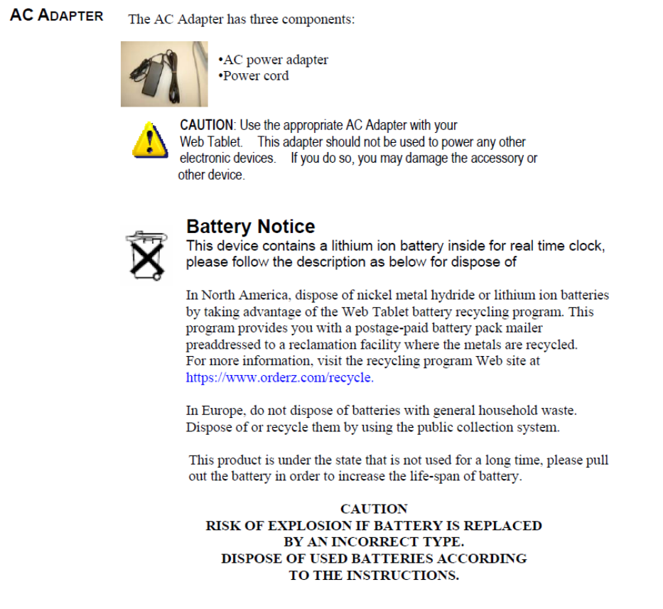
CAUTION ON LITHIUM BATTERIES
There is a danger of explosion if the battery is replaced incorrectly. Replace only with the
same or equivalent type recommended by the manufacturer. Discard used batteries
according to the manufacturer’s instructions.

6
Product Disposal
Outside the European Union - If you wish to dispose of used electrical and
electronic products outside the European Union, please contact your local
authority so as to comply with the correct disposal method.
Within the European Union:
EU-wide legislation, as implemented in each Member State, requires
that waste electrical and electronic products carrying the mark (left)
must be disposed of separately from normal household waste. This
includes monitors and electrical accessories, such as signal cables or
power cords. When you need to dispose of your display products,
please follow the guidance of your local authority, or ask the shop
where you purchased the product. The mark on electrical and
electronic products only applies to the current European Union
Member States.
Please follow the national guidelines for electrical and electronic product disposal.
Cleaning Caution
zDisconnect the AC power and remove the battery pack (s) before cleaning.
zWipe the FMIX using a clean cellulose sponge or chamois cloth dampened with
a solution of nonabrasive detergent and a few drops of warm water and remove
any extra moisture with a dry cloth.
zTo clean the LCD panel, gently wipe it with a piece of soft dry cloth.
7
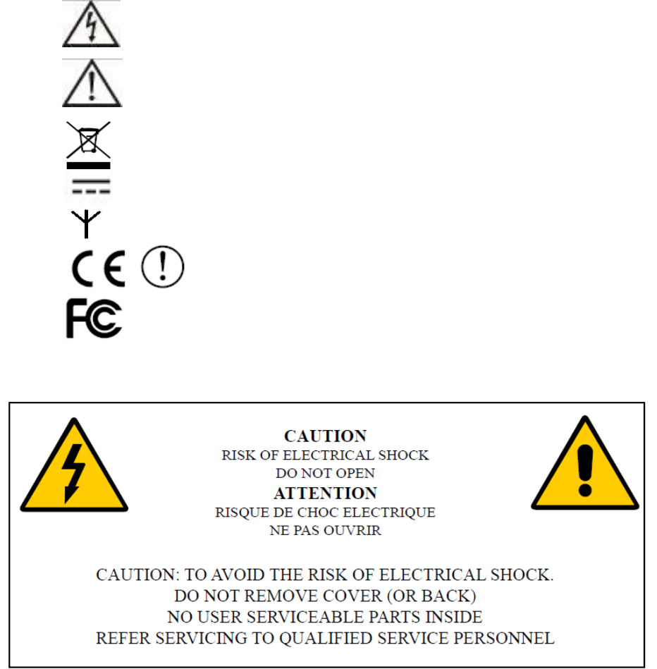
Explanation of Graphical Symbols
The following symbol may appear on FMIx
This symbol warns the user that un-insulated voltage within the unit
may have sufficient magnitude to cause electric shock. Therefore, it
is dangerous to make any kind of contact with any part inside this
unit.
This symbol alerts the user that important information concerning the
operation and maintenance of this unit has been included. Therefore,
the information should be read carefully in order to avoid any
problems.
Product Comply with 2002/96/EC
Direct Current
Wireless Symbol
Compliance with R&TTE Directive 1995/EC
Federal Communication Commission Notice (USA)
8
Table of Contents
1. Introduce ......................................................................................................................9
Applications...........................................................................................................9
2. Item Checklist ............................................................................................................10
3. System View .............................................................................................................. 11
3.1. Front View........................................................................................................... 11
3.2.1. Left Side View ...........................................................................................13
3.2.2. Right Side View.........................................................................................14
3.2.3. Up Side View ............................................................................................15
3.2.4. Bottom Side View......................................................................................15
3.3. Rear View............................................................................................................16
4. Basic Operations........................................................................................................17
4.1. Install the Battery Pack........................................................................................17
4.2. Connect the AC Power Adapter...........................................................................17
4.3. Turn ON the FMIx................................................................................................18
4.4. Using the Stylus Pen ...........................................................................................18
5. Mounting ....................................................................................................................19
Wall Mounting Installation ...................................................................................19
6. Drivers Installation......................................................................................................20
6.1. Chipset Driver Installation ...................................................................................20
6.2. Touch Panel Driver Installation(USB Interface) ...................................................21
6.3. VGA Driver Installation ........................................................................................24
6.4. LCD Brightness setting .......................................................................................26
6.5. Screen Rotation Setting ......................................................................................26
6.6. Audio Driver Installation.......................................................................................27
6.7. Button Driver Installation .....................................................................................28
6.8. LAN Driver Installation.........................................................................................30
6.9. Wireless LAN Driver Installation..........................................................................30
7. Replace Components.................................................................................................32
7.1. Remove the Battery Pack ...................................................................................32
7.2. Replace the Memory Module ..............................................................................32
7.3. Replace the Storage Device................................................................................33
8. Specification...............................................................................................................34
8.1 Detail Product Specification ..........................................................................34
8.2 Classification.................................................................................................35
9. Contact Information....................................................................................................36
9
1. Introduce
FM1x, an Intel Atom platform based WebPAD with 12.1” LCD, it provides two USB2 host ports,
10/100/1000 base-T RJ45 port, standard CRT port, headphone-out and Ext. Microphone-in jacks
for I/O interface, Also contains 4 function keys for customized programming, built-in
IEEE802.11b/g/n WLAN for wireless communication. Likewise, FM1x offers the storage expansion
capability through the SD/MMC slot, and security identify function via optional Smart Card reader
and RFID reader, The FM1x absolutely be a perfect model for hospital/business IT management,
entertainment, VOIP application and distinctive application in various fields.
Applications
The FMIx series Web PC is designed to fit hospital environments. This product will not use
in Patient vicinity. Its durability and strength also makes it an ideal choice for public access
computers. Some possible applications include:
Preoperative Information System (PIS)
oPre-operative data recording
oPost-operative data recording
Bedside terminal
oReal-time patient data recording
oPatient communication system
oBedside entertainment
Medical information processing
oComputer-based testing center
oElectronic medical record
oMobile nursing station
oInteractive clinical education
oElectronic booking system
10
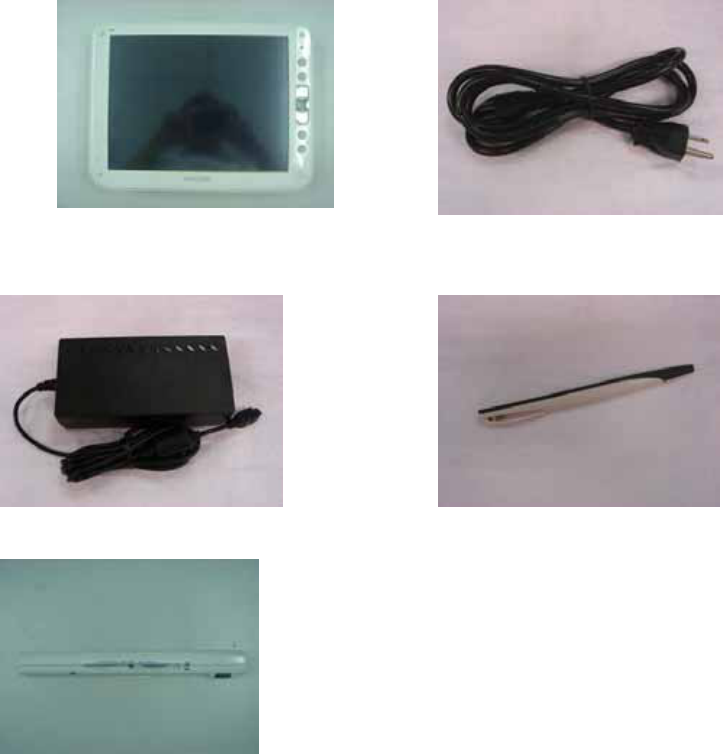
2. Item Checklist
Take out the system unit from the carton. Remove the unit by carefully clutching the foam
inserts and remove slowly to protect the system. The following contents should be found in
the carton:
a. System b. Medical Grade Power cord for US
Standard
c. Medical Power Adapter d. Stylus Pen
f. Battery Pack(4S1P)
11
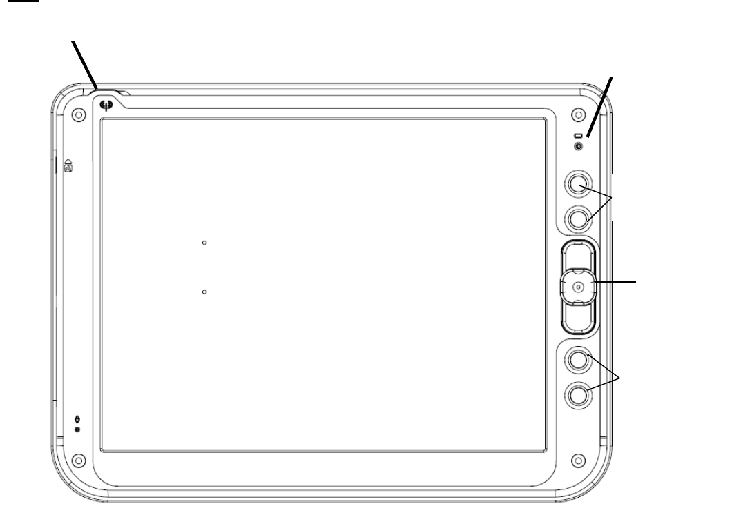
3. System View
Refer to the pictures below to identify the components.
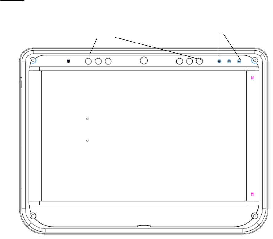
3.1. Front View
4:3
Trackpoint
Programmable
Buttons
Wireless LED
Power/ Char
g
er LED
Programmable
Buttons
12
16:10
Programmable
Buttons
LED Indicator
13
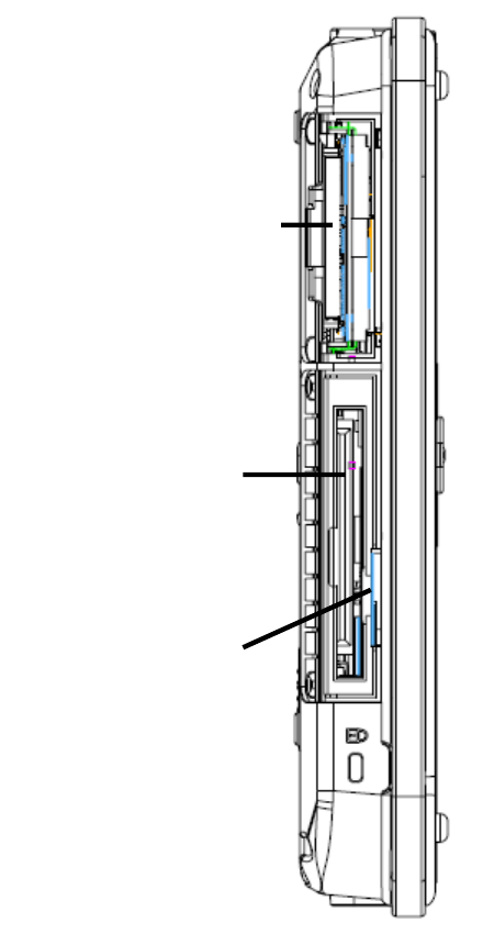
3.2.1. Left Side View
Stora
g
e Device Ba
y
Smart Card Reade
r
SD/MMC Reader
14
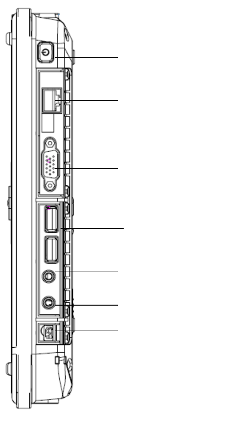
3.2.2. Right Side View
LAN Jack
USB Port x 2
DC-In Jack
Ear
p
hone Jack
Ext. Micro
p
hone Jack
VGA Port
Power On/Off Button
15
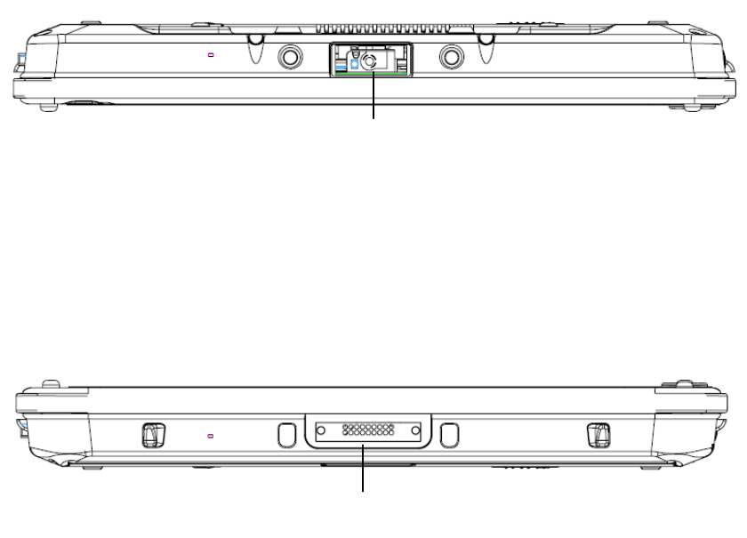
3.2.3. Up Side View
3.2.4. Bottom Side View
Bar Code Reader
Cradle Port
16
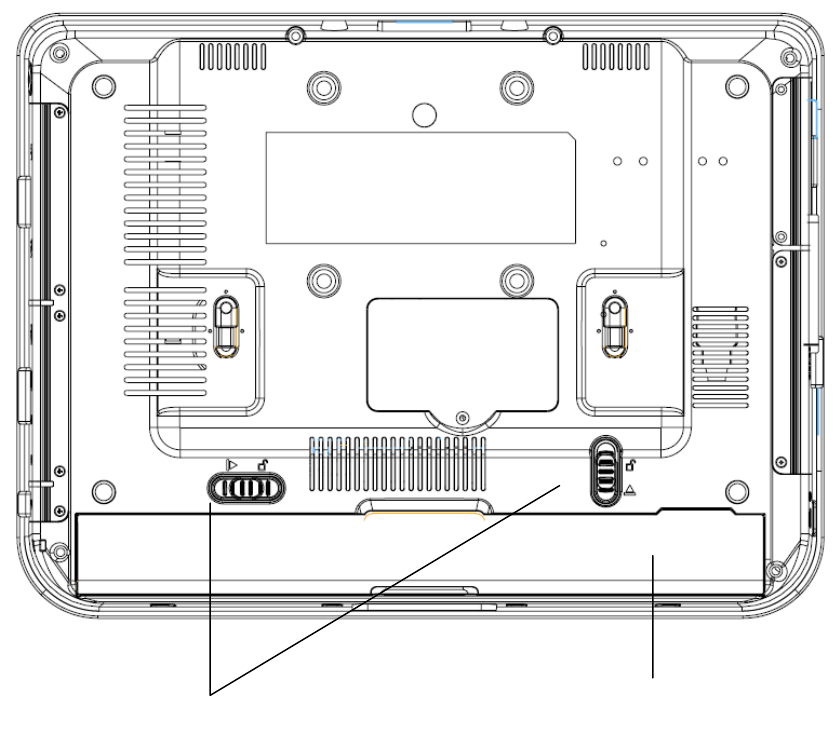
3.3. Rear View
Batter
y
Pack
Batter
y
Pack Latch
17
4. Basic Operations
This section helps you to start using your FM1X-A12.
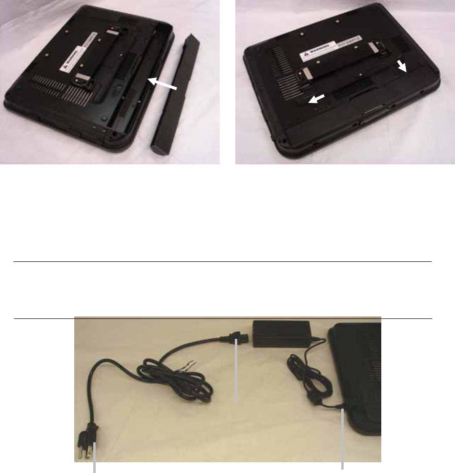
4.1. Install the Battery Pack
a. Insert the battery pack until it clicks into
place.
b. Slide both Battery Release tabs to the
lock position.
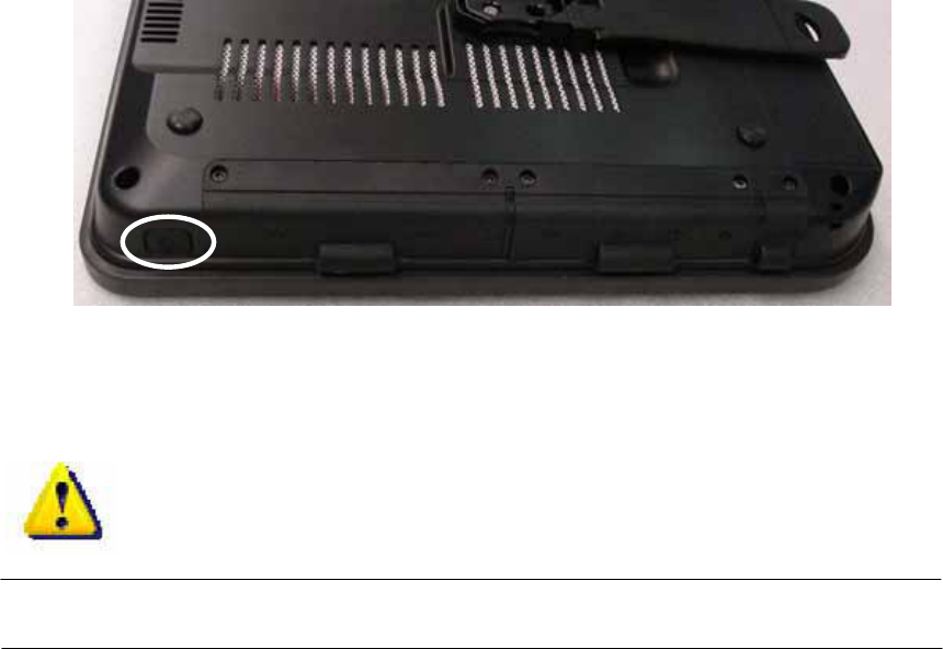
4.2. Connect the AC Power Adapter
IMPORTANT! Damage may occur if you use a different adapter to power the FMIx or
use the FMIx’s adapter to power other electrical devices. You may damage both your
battery pack(s) and the FMIX with a faulty AC-DC adapter.
(3) Insert the
DC power plug
(1) Connect this
end of the power
cord to the AC-DC
converte
r
(2) Plug the AC
power cord into an
electrical outlet
18
4.3. Turn ON the FMIx
a. Press the power button and release at the right side of the system.
4.4. Using the Stylus Pen
IMPORTANT! DO NOT touch the screen with sharp objects or any other type of
writing instrument. It can damage the screen.
The FMIx has a touch-sensitive screen. It allows you to use your stylus pen or finger to
interact with the device. With the FMIx, you can input data using the full screen area.
19
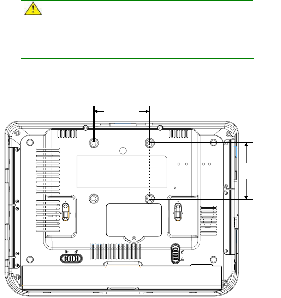
5. Mounting
The FMIx Web PAD can be mounted onto the wall or stand.
CAUTION:
When mounting the monitor, take care to tighten the retention screws or bolts
until fully secure, but do not over tighten. Over tightening the retention screws or
bolts may cause them to become stripped, rendering them useless.
Wall Mounting Installation
The FMIx has Video Electronics Standards Association (VESA) standard mounting holes
tapped into the rear panel. The standard holes are M4 set at 75 mm x 75 mm apart
75 mm
75 mm
20
6. Drivers Installation
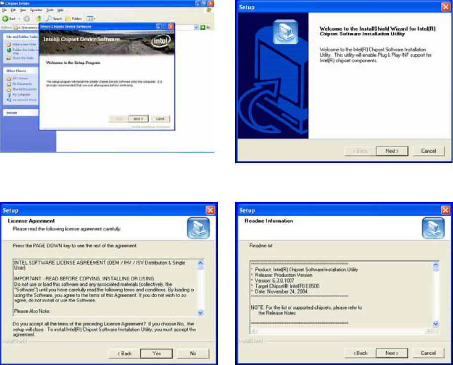
6.1. Chipset Driver Installation
a. Click the Setup.exe on the My
Computer window.
b. Click the “Next” button on the Setup
window.
c. Click the “Yes” button on the Setup
window.
d. Click the “Next” button on the Setup
window.
21
e. Select “Yes, I want to restart my
computer now” and click the “Finish”
button on the Setup window.
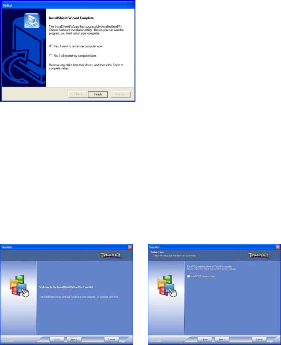
6.2. Touch Panel Driver Installation(USB Interface)
a. Click Setup.exe b. Click “Next” Button
22
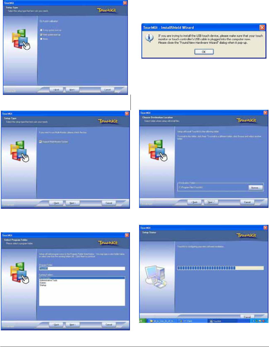
Click the “Next” button Click the “OK” button
Enable check box, and Click the “Next”
button
c. Click the ”Next” button
Click the “Next” button
23
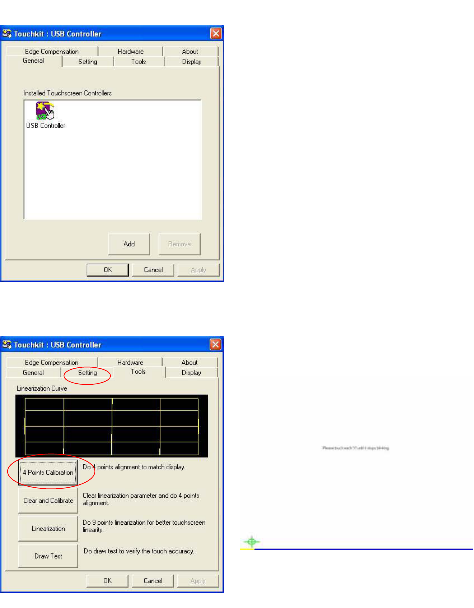
Click the “OK” button
Select “Setting for Touch Panel Calibration Click “+” to Calibrate touch panel”
24
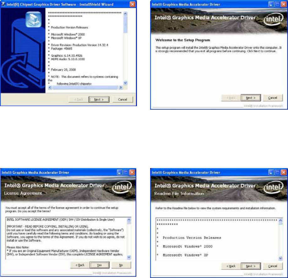
6.3. VGA Driver Installation
a. Click the “Setup.exe” on the My
Computer window.
Click the “Next” button on the Intel(R)
Chipset Graphics Driver Software-
InstallShield(R) Wizard window.
Click the “Yes” button b. Click the “Next” button
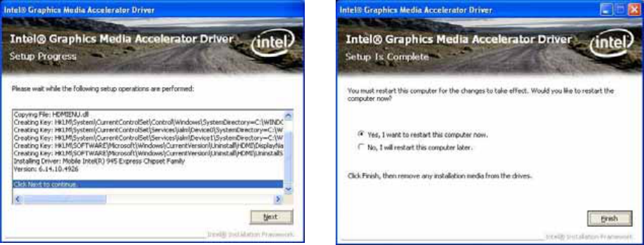
25
c. Click the “Next” button d. Select “Yes, I want to restart my , and
Click the “Finish” button
26
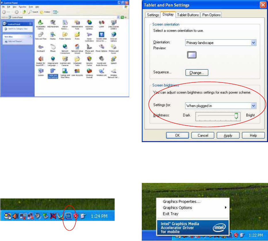
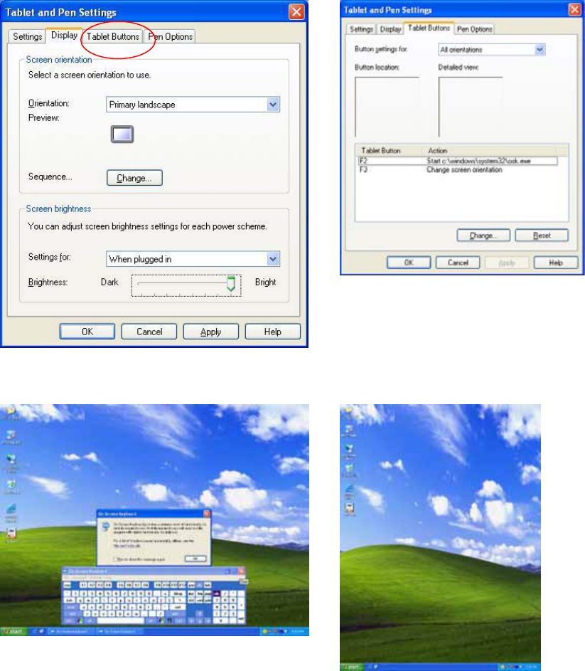
6.4. LCD Brightness setting
Choose “Tablet & Pen settings” icon a. LCD Brightness setting
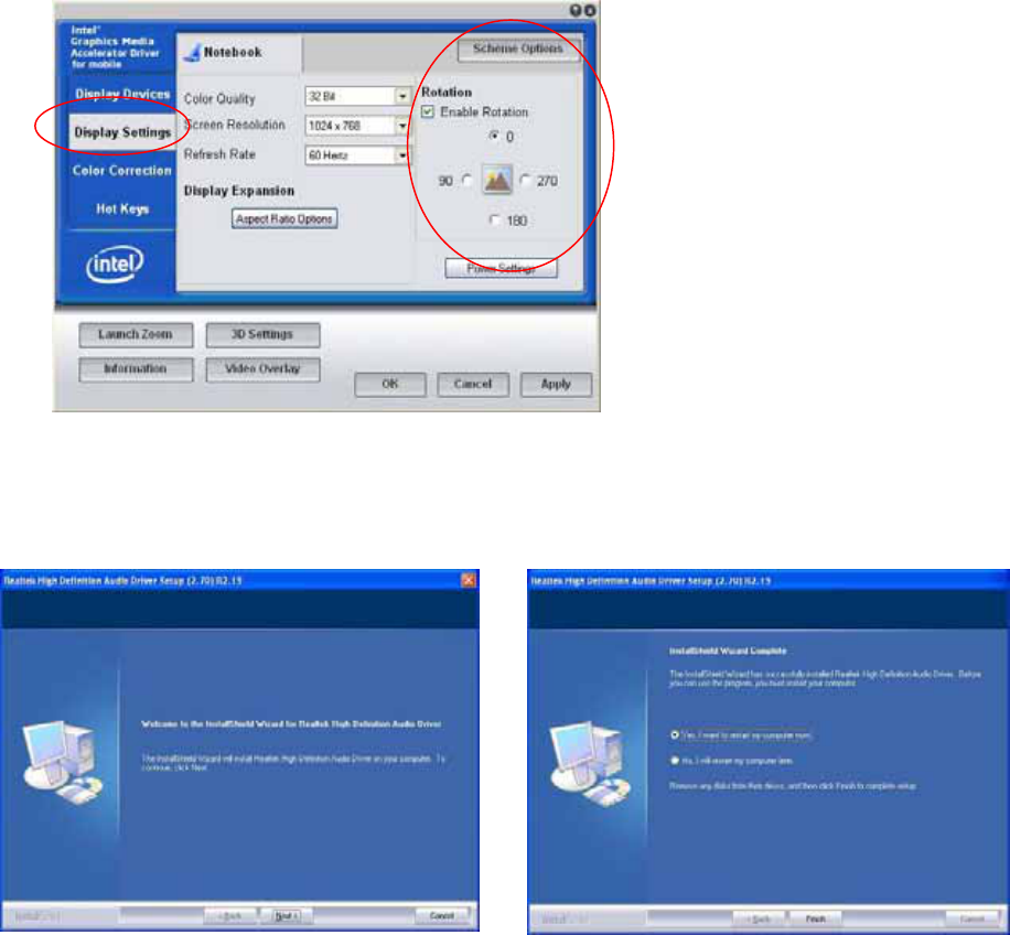
6.5. Screen Rotation Setting
Choose “Intel chipset Graphics setting” icon b. Select “Graphics Properties”
27
a.) Choose “Display setting
b.) Enable Rotation setting
6.6. Audio Driver Installation
a. Select “Setup.exe “ on Audio driver
folder
Finished. Select “Yes, I want to restart my
computer now” and click the “Finish”
button.
28
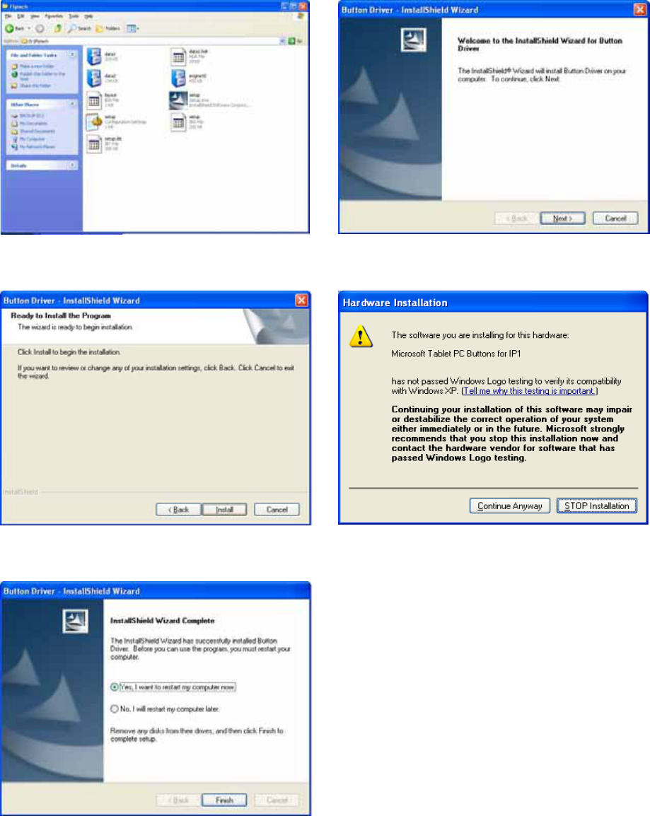
6.7. Button Driver Installation
Select “Setup” on the My Computer
window.
Click the “Next” button on the Button
Driver – InstallShield Wizard window.
Click the “Install” button on the Button
Driver – InstallShield Wizard window.
Click the “Continue Anyway” button on the
Hardware Installation window.
Select “Yes, I want to restart my computer
now” and click the “Finish” button.
29
6.7.1. Programmable Software Buttons-“Customize Setting”
F2 - On Screen Keyboard F3 – Screen Rotation
30
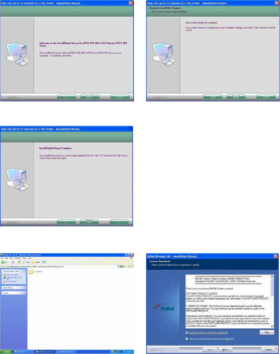
6.8. LAN Driver Installation
a. Select “Setup.exe” on the My
Computer window.
b. Select “next” button on the My
Computer window.
c. Select “finish” button
6.9. Wireless LAN Driver Installation
a. Click the “setup.exe” on the My
Computer window.
b. Select “I agree”, and Click the “Next”
Button
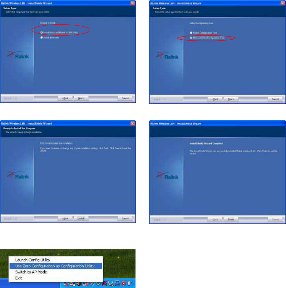
31
c. Click the “Next” Button d. Click the “Next” button
e. Click the “Next” button. f. Click the “Finish” button.
You can Select “Use Zero Configuration”
setting on the “Ralink Wireless Utility” to
change Wireless utility through “Microsoft
wireless utility”
32
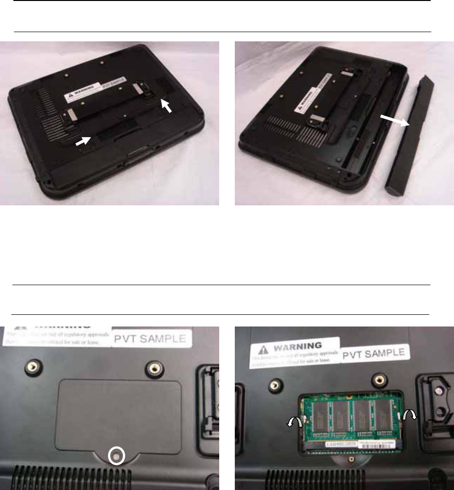
7. Replace Components
7.1. Remove the Battery Pack
IMPORTANT! Never attempt to remove the battery pack while the FMIX is turned ON,
as this may result in the loss of working data.
a. Slide both battery release tabs to the
unlock position.
b. Pull the battery pack away from the
body.
7.2. Replace the Memory Module
IMPORTANT! DO NOT touch the golden contacts as this can damage the Ensure
memory that the notches in the memory module line up with the DIMM slot keys.
a. Remove the screw (1). b. Use your fingers to push the two metal
latches on the side of the slot click.
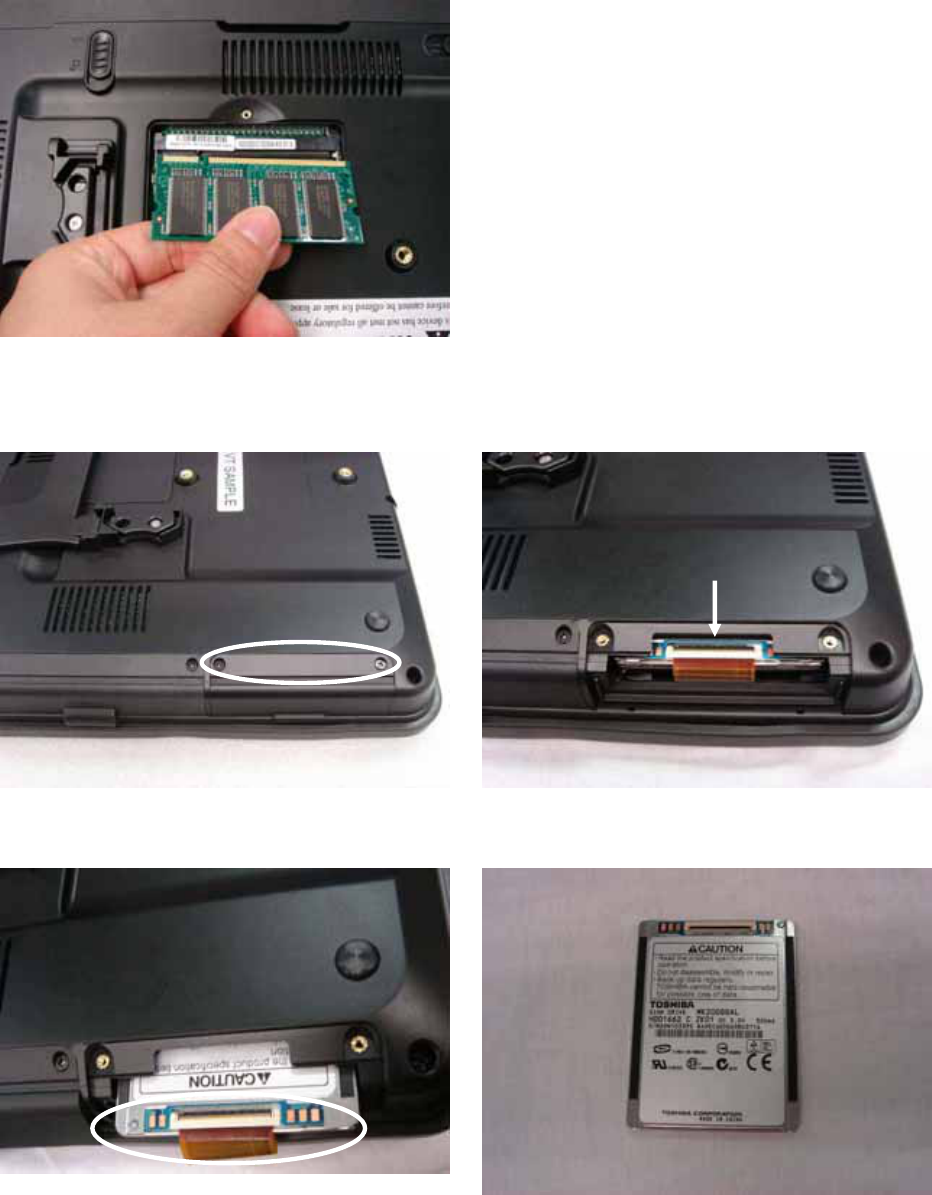
33
c. Remove the memory module from the
slot.
7.3. Replace the Storage Device
a. Remove the screws (2) that secure the
HDD cover.
b. Slide the HDD towards you.
c. Disconnect the HDD cable carefully. d. Replace the 1.8” HDD.

34
8. Specification
8.1 Detail Product Specification
Model FMIx
Motherboard CPU Intel Atom N270 @1.6GHz
Core Logic Intel 945GSE
SO-DIMM (DRR II) Standard 1GB, Max. 2GB
VGA & Graphic Built-in Intel 945GSE
LCD & Touch LCD Size 12.1” TFT LCD, Normal LCD 4:3
Or 12.1” TFT LCD, Wide Screen LCD 16:10
Brightness Around 200 nits
Resolution XGA 1024 x 768 , with CCFL BL
Or WXGA 1280 x 800, with LED BL
Touch Type 12.1” Resistive Type Touch Screen
Storage & Expansion HDD or
Compact Flash
1.8” SATA SSD 16/32 GB
or Compact Flash Card 2/4/8/16GB
Card Reader SD/MMC/ Option slot x 1 & Smart Card Reader x 1
Mini PCIe Slot Mini PCIe Internal Slot x 1
Input/Output Ports USB2.0 Two ports
LAN 1 x RJ45 connecter (10/100/1000 Mbps)
Audio Jack 1 x Headphone Jack
CRT Output 1 x 15-pin female connecter
Microphone 1 x External Jack & 1 x Built-in
Cradle Connector 18-pin connecter
Built-in Audio Mono microphone and stereo speakers
Indicators & Buttons LED 2 (Power/Charge & Wireless for 4:3)
Or 3 (Power/Charge, Storage Access & Wireless for
16:10)
Hotkeys 6 for 4:3 Bezel (2 mouse key included)
6 for 16:10 Bezel
Wireless Wi-Fi Built-in 802.11 b/g/n module (USB)

35
Bluetooth-Option Built-in V2.1 +EDR odule (USB)
Power & Battery Power Adapter Cincon Electronics Co., LTD
TR60M19
Input: 90 ~240Vac
Output: DC19V, 3.15A
Battery Pack Rechargeable Li-ion Battery
(4S1P 14.8V @2400mAh)
Battery Running Time 3~4 hours for Normal usage
Environmental EMC & Safety CE/FCC Class B, cUL
Operating Temperature +41 堕to +95 堕F (+5 堕to +35 堕C)
Storage Temperature/
Transportation
Temperature: 0°C ~ 45°C
Humidity: 10% ~ 95% Non-condensing
Atmospheric pressure: 500~1060 hPa
IP Level IPX0
Product Life Time 3 years
Dimension (W x H x D) 12.32 x 9.25 x 1.40 Inch (313 x 235 x 35.7 mm)
Net Weight 3.74 lbs (1.7 kgs, with Battery)
Options Operating System Windows XPe, -Home, -Pro-Home, Vista
Bar Code Scanner Symbol SE4400
Stylus Pen 1
8.2 Classification
oPower by Class I power adapter:
oNo protection against the ingress of water: IPX0
oMode of operation: Continuous Operation
oThe equipment not suitable for use in the presence of a
flammable anesthetic mixture with air or with oxygen or nitrous
oxide: Not AP or APG Category
oNot for LifeͲSupport

36
9. Contact Information
MoBitS Electronic, Inc.
Phone: +886-2-2603-9288
Fax: +886-2-2601-2877
World Wide Web: www.mo-bits.com
Sales Email: sales@mo-bits.com
Federal Communication Commission Interference Statement
This equipment has been tested and found to comply with the limits for a Class B digital device,
pursuant to Part 15 of the FCC Rules. These limits are designed to provide reasonable
protection against harmful interference in a residential installation. This equipment generates,
uses and can radiate radio frequency energy and, if not installed and used in accordance with
the instructions, may cause harmful interference to radio communications. However, there is
no guarantee that interference will not occur in a particular installation. If this equipment does
cause harmful interference to radio or television reception, which can be determined by turning
the equipment off and on, the user is encouraged to try to correct the interference by one or
more of the following measures:
zReorient or relocate the receiving antenna.
zIncrease the separation between the equipment and receiver.
zConnect the equipment into an outlet on a circuit different from that to which the receiver
is connected.
zConsult the dealer or an experienced radio/TV technician for help.
FCC Caution: Any changes or modifications not expressly approved by the party responsible
for compliance could void the user's authority to operate this equipment.
This device complies with Part 15 of the FCC Rules. Operation is subject to the following two
conditions: (1) This device may not cause harmful interference, and (2) this device must
accept any interference received, including interference that may cause undesired operation.
Radiation Exposure Statement
This EUT is compliance with SAR for general population/uncontrolled exposure limits in
ANSI/IEEE C95.1-1999/ IC RSS-102 and had been tested in accordance with the
measurement methods and procedures specified in OET Bulletin 65 Supplement C.