Qingdao Hisense Intelligent Commercial System HM518 Tablet POS User Manual HM518
Qingdao Hisense Intelligent Commercial System Co., Ltd. Tablet POS HM518
User Manual

TabletPOS
HM518USERMANUAL
QingdaoHisenseIntelligentCommercialSystemCo.,Ltd.
Part1.SystemIntroduction
01.SafetyNoticesBeforeInstallationorUse
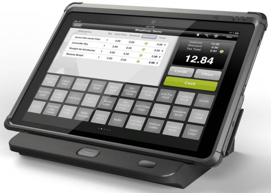
02.SystemIntroduction
03.GeneralSpecifications
04.FrontView
05.BackView
06.Dimension
07.I/OView
Part2.SystemInstallation
01.CheckingtheLocationforInstallation
02.BeforeConnectingPeripherals
03.ConnectingDCpowersupplycable
04.Package
Part3.ProductLayout
01.Motherboardlayout
02.MotherboardModule&Function
03.Productlayout
04.ProductModule&Function

Part1.SystemIntroduction
01. SafetyNoticesBeforeInstallationorUse
Caution:
☆ Itisrequiredgroundedwellandthesupplyvoltageshallbestable,andyoumust
confirmthatthevoltageoftheoutletprovidesshallbeinlinewiththevoltage
markedonthelableoftheunit.
☆ Besurenottosprinkleanyliquidorfallanyobjectintotheunit.
☆ Besurenottokeepheavy,strenuousmovement,shake&heavystrikeaway
fromthePOS.
☆ Donotswitchonoroffthehostfrequently,becauseitiseasytoresultin
damageonthemachine.
☆ Besurenottounplugorpluginanylivepartorexternaldevicewhentheyarein
energizedstate,andtheconnectingcablesofthePOSbetweenpartsshallbe
connectedsecurely.
☆ Besureneithertolengthencablenortoreplacepartsatyourwill,ifyouhave
anydemand,pleasecontactwiththereseller.
☆ Theunitshallbeusedunderdry,ventilated&cleanenvironmentawayfrom
sunlight.
☆ Incaseofsafetyfault,suchaspeculiarsmell,abnormalsound,leakageand
otherfaults,youmustswitchoffthepowersupplyatonceandthencontact
withreseller.
☆ TheRJ11portatthebackofthehostisconnectedwiththecashdrawer,asitis
notacommunicationport,usersshallnotusetheportfordial‐upnetworking.
☆ TheproductisaLevelBone,itmaycauseradiointerferenceinliving
environment.Insuchcase,usersmayneedtotakepractical&feasiblemeasures
againsttheinterference.
☆ WhenthePOSisnotinuse,youshallswitchoffpowersupply.
☆ Staticmaydamagetotheintegratedcircuitinthehostmachine.
☆ Pleaseuseoriginalcharger,Otherwise,Itmayresulttodanger.Whenyouusea
chargerforcharging,adaptershallbeinstalledneartheequipmentandshallbe
easilyaccessible.
DescriptionManufacturer ModelInputOutput
Switching
PowerAdapter
FSPGROUP
INC.FSP040‐RHAN2AC100~240V DC12V/3.33A
DockingStation
Qingdao
Hisense
Intelligent
Commercial
SystemCo.,Ltd
HM518DC12V/3.33A DC12V/3.33A

☆ ThisproductconformswithstandardEN50332.Usecarefulwiththeearphone
maybepossibleexcessivesoundpressurefromearphonesandheadphonescan
causehearingloss.
☆ TheproductshallonlybeconnectedtoaUSBinterfaceofversionUSB2.0,this
interfacecanprovidemaximumcurrentof500mA.
☆ ExtremeOperatingTemperature:40℃
☆ ThedevicecomplieswithRFspecificationswhenthedeviceusedat10mmform
yourbody.
☆ DeclarationOfConformityHereby,ThisTabletPOSisincompliancewiththe
essentialrequirementsandotherrelevantprovisionsofdirective1995/5/EC.
☆ Customercannotmodifysystemsoftware,including"root"oranyothercrack
methods.Thesemethodsarenotpermitted.Ifyoudothis,youwillloseour
Guarentee.
CAUTION:RISKOFEXPLOSIONIFBATTERYISREPLACEDBYANINCORRECTTYPE.
DISPOSEOFUSEDBATTERIESACCORDINGTOTHEINSTRUCTIONS.
Warning:
1.Forcontinuedprotectionagainstriskofelectrostatic,itcanresultinsystemorPOS
terminaldamaged
2.Dangerofexplosionifbatteryisincorrectlyreplaced.Replaceonlywiththesameor
equivalenttypeasrecommendedbythemanufacturer,Discardusedbatteries
accordingtothemanufacturer’sinstructions.
3.Donotremovetheperipheraldevicebeforeturnoffthesystem.
Turnonthesystemafterturningonperipheraldevice,andturnoffperipheraldevice
afterturnoffthesystem
FCCWarning:
ThisequipmenthasbeentestedandfoundtocomplywiththelimitsforaClassB
digitaldevice,pursuanttopart15oftheFCCRules.Theselimitsaredesignedto
providereasonableprotectionagainstharmfulinterferenceinaresidential
installation.Thisequipmentgenerates,usesandcanradiateradiofrequencyenergy
and,ifnotinstalledandusedinaccordancewiththeinstructions,maycauseharmful
interferencetoradiocommunications.However,thereisnoguaranteethat
interferencewillnotoccurinaparticularinstallation.Ifthisequipmentdoescause
harmfulinterferencetoradioortelevisionreception,whichcanbedeterminedby
turningtheequipmentoffandon,theuserisencouragedtotrytocorrectthe
interferencebyoneormoreofthefollowingmeasures:
•Reorientorrelocatethereceivingantenna.
•Increasetheseparationbetweentheequipmentandreceiver.
•Connecttheequipmentintoanoutletonacircuitdifferentfromthattowhichthe
receiverisconnected.
•Consultthedealeroranexperiencedradio/TVtechnicianforhelp.
Caution:Anychangesormodificationstothisdevicenotexplicitlyapprovedby
manufacturercouldvoidyourauthoritytooperatethisequipment.
Thisdevicecomplieswithpart15oftheFCCRules.Operationissubjecttothe
followingtwoconditions:(1)Thisdevicemaynotcauseharmfulinterference,and(2)
thisdevicemustacceptanyinterferencereceived,includinginterferencethatmay
causeundesiredoperation.
Themanufacturerhastherighttomodifycontentsoftheinstructionbookbut
withoutpriorannouncements!
02.SystemIntroduction
Theexteriordesignandspecificationsofproductcanbechangedwithoutprior
noticeinordertoimprovequality.

03.GeneralSpecifications
Item Description
CPU Intel Celeron, N2807
Memory 2G Byte RAM
Storage 32GByte eMMC
System Win8.1 Pro/Embedded/with Bing
Operating Temperature 0℃ ~ +40℃
Operating Humidity 10% ~ 90%
Display
TFT LCD 10.1"TFT LCD,1280*800
Brightness 300cd/m²
Touch Screen Multi-touch capacitive touch panel(10points)
Port
Tablet
MSR 3 Tracks
Scanner 1x1D Scanner
Camera Rear:5MP, AF focus
NFC Supports MIFARE one and MIFARE CPU card
IC Card Reader 1 xIC Card Reader
Micro SD 1 x Micro SD slot
SIM Card 1x SIM slot (WCDMA)
Audio Built-in 1W speaker ;Microphone; 1 x 3.5-mm stereo
headphone
USB 1x USB2.0 Host
WIFI Wi-Fi® 802.11a/b/g/n/ac 2.4GHz/5GHz
BT BT 4.1
DC input 1 x DC jack (12V)
Docki
ng
station
VGA 1 * VGA reserved for 2nd display
USB 3x USB2.0 Host
LAN 1 * RJ-45 (100Mbps LAN)
Cash Drawer 1 * RJ-11 12V/24V for cash drawer(24V default)
Serial Ports 2* RS-232 COM,
COM1(RX/TX/GND),COM2(RX/TX/GND/DTR/DSR)
DC input 1 x DC jack (12V)
Power adapter AC 100-240V / DC 12V 3.33A
Battery 4000mAh 7.4V
Dimensions
Tablet(mm) 276 x 193 x 23.8
Tablet Weight(kg) 1.0
Docking station(mm) 280 x 170.8 x 72.3
Docking station Weight(kg) 0.8
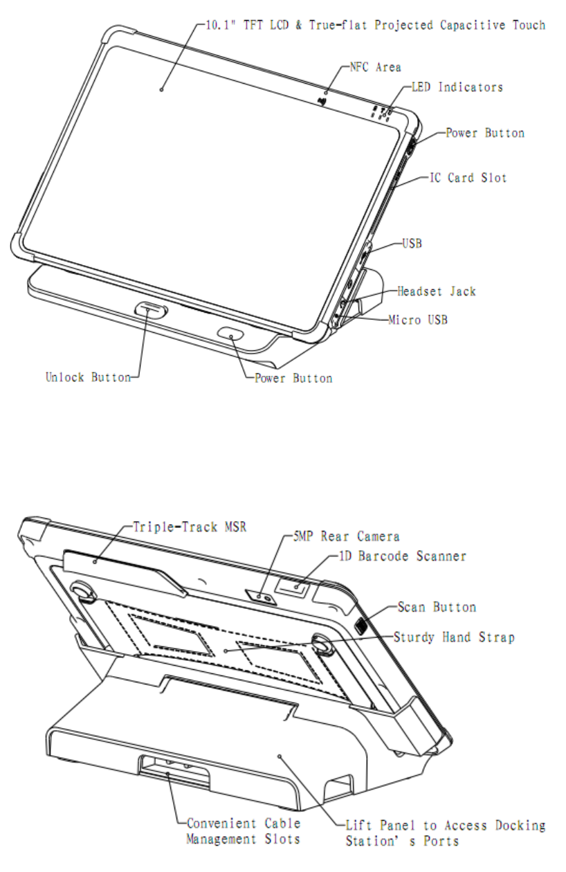
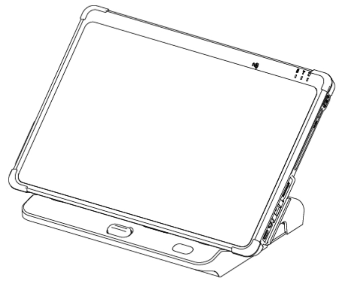
04.FrontView
05.BackView
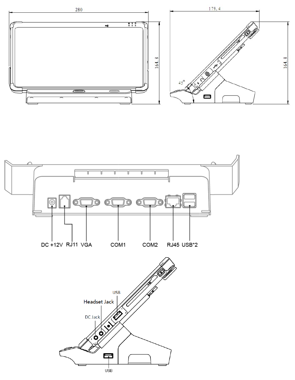
06.Dimension
07.I/OView
Part2.SystemInstallation
01.CheckingtheLocationforInstallation
Itisimportanttochooseasafeandsecureplacetoinstalltheterminal.
••Chooseadeskortablebigandstrongenoughtosupporttheweightofthe
systemandperipherals.
••Chooseaflat,hardsurface.Carpetedareacangeneratestaticelectricitythatcan
altermemoryordamagesystemcomponents.
••Makesureasysteminstalledinawell‐ventilatedplaceandkeepthespacefree
aroundthesystem.
••Chooseappropriateenvironmentalconditionssuchascoolanddryplaces.Avoid
humidanddustyplaces.Alsoavoiddirectsunlight,rapidlychangingtemperatures,or
placingthesystemnearheatsources.
••Selecttheappropriatevoltage.Connectalltheequipmentintoanisolatedoutlet
topreventstaticelectricityandshortcircuit.
••wheresufficientpoweroutletsareavailableforprintersandotherperipheral
devices.
••Donotinstallnearelectromagneticandelectricaldevices,suchasphonesand
electricmoters,thatcancausesystemdamage.
••Thesocket‐outletshallbeinstalledneartheequipmentandshallbeeasily
accessible.
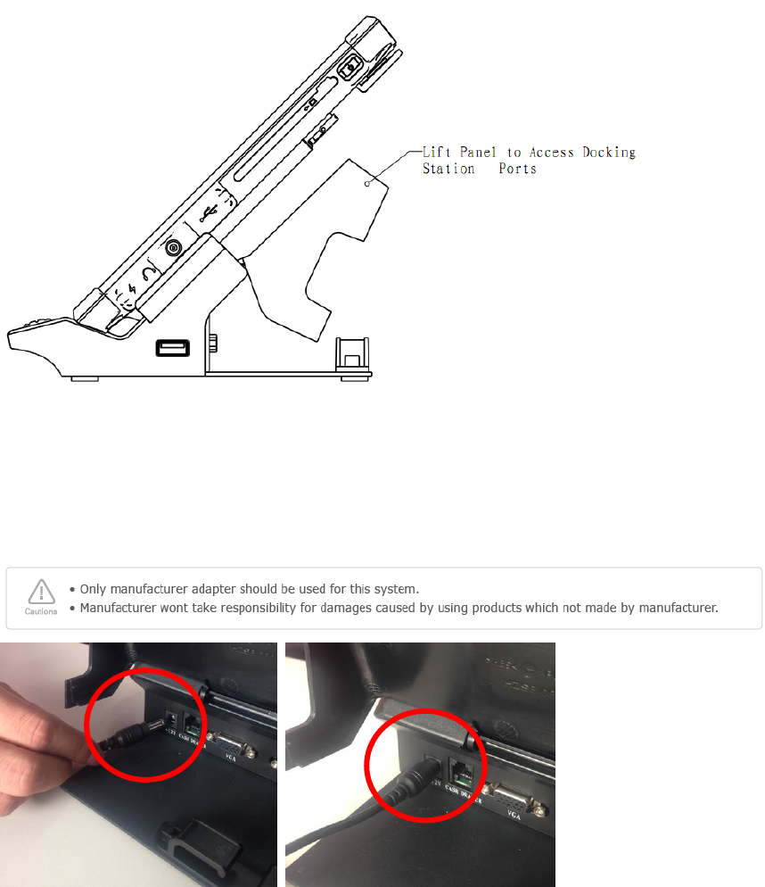
02.BeforeConnectingPeripherals
Toconnectperipheralsfirstremovethe'Interfacecover',whichisinthebottomof
thesystem.
03.ConnectingDCpowersupplycable
Dockingstation:ConnecttheDCpowercabletotheDCpowerinputconnectorat
thebottomofthesystem.(Adapter100V‐240Vfreevoltageofthesystemcanbeused.)
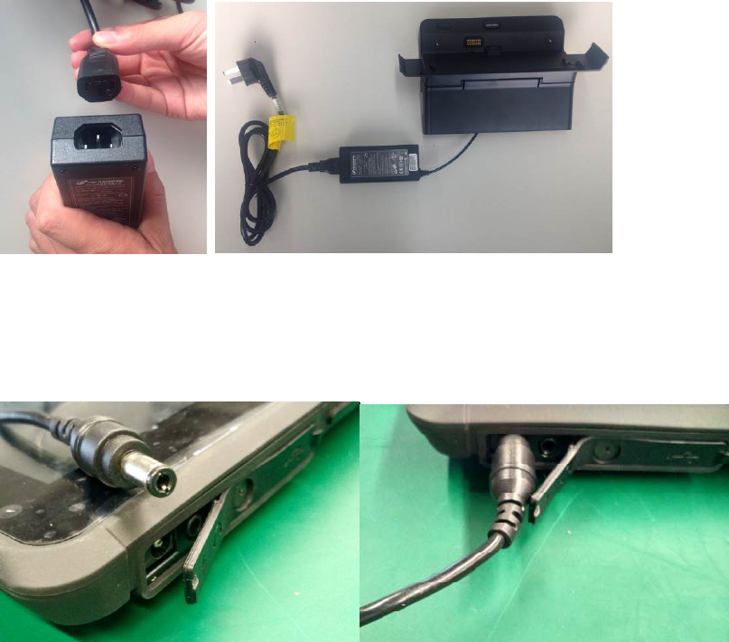
Tablet:whenusing12Vadapterfortabletcharging,ConnecttheDCpowerinputcableto
theDCpowerinputPortatthesideofthetablet.
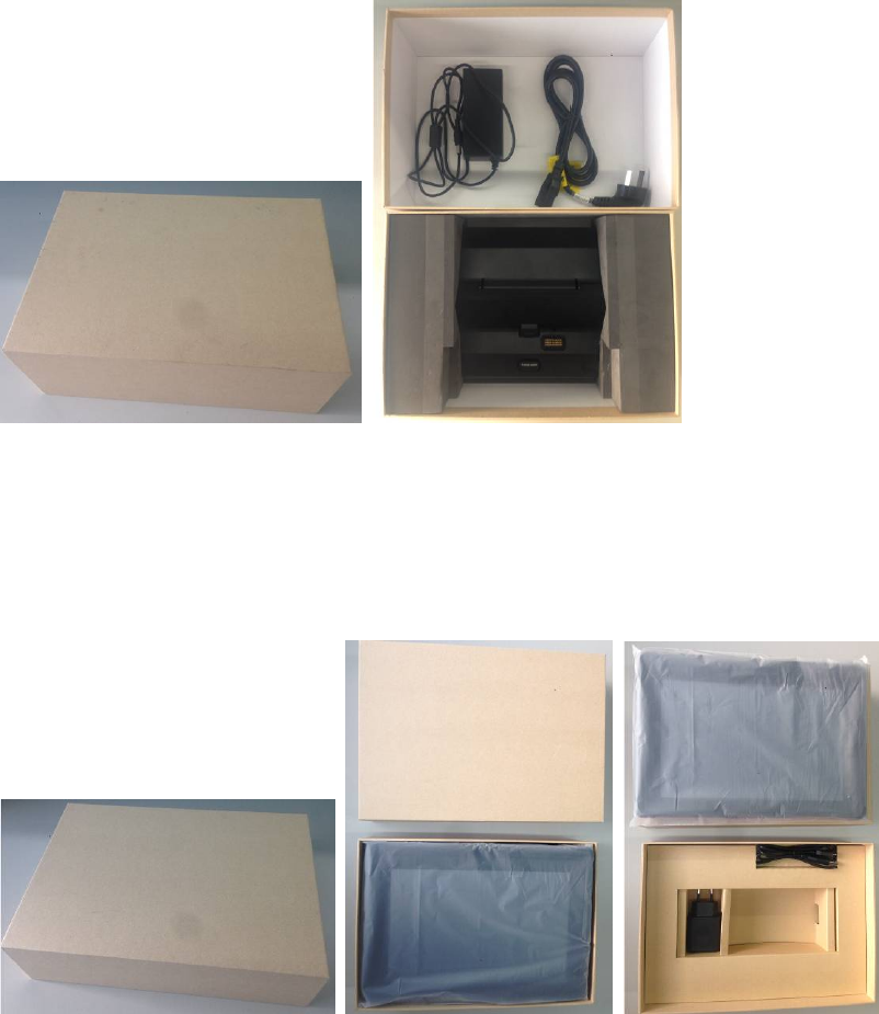
04.Package
a.DockingstationPackage:
ACadapter,PowerCord,Dockingstation
b.TabletPackage:
ACadapter,PowerCord,Tablet
Part3.ProductLayout
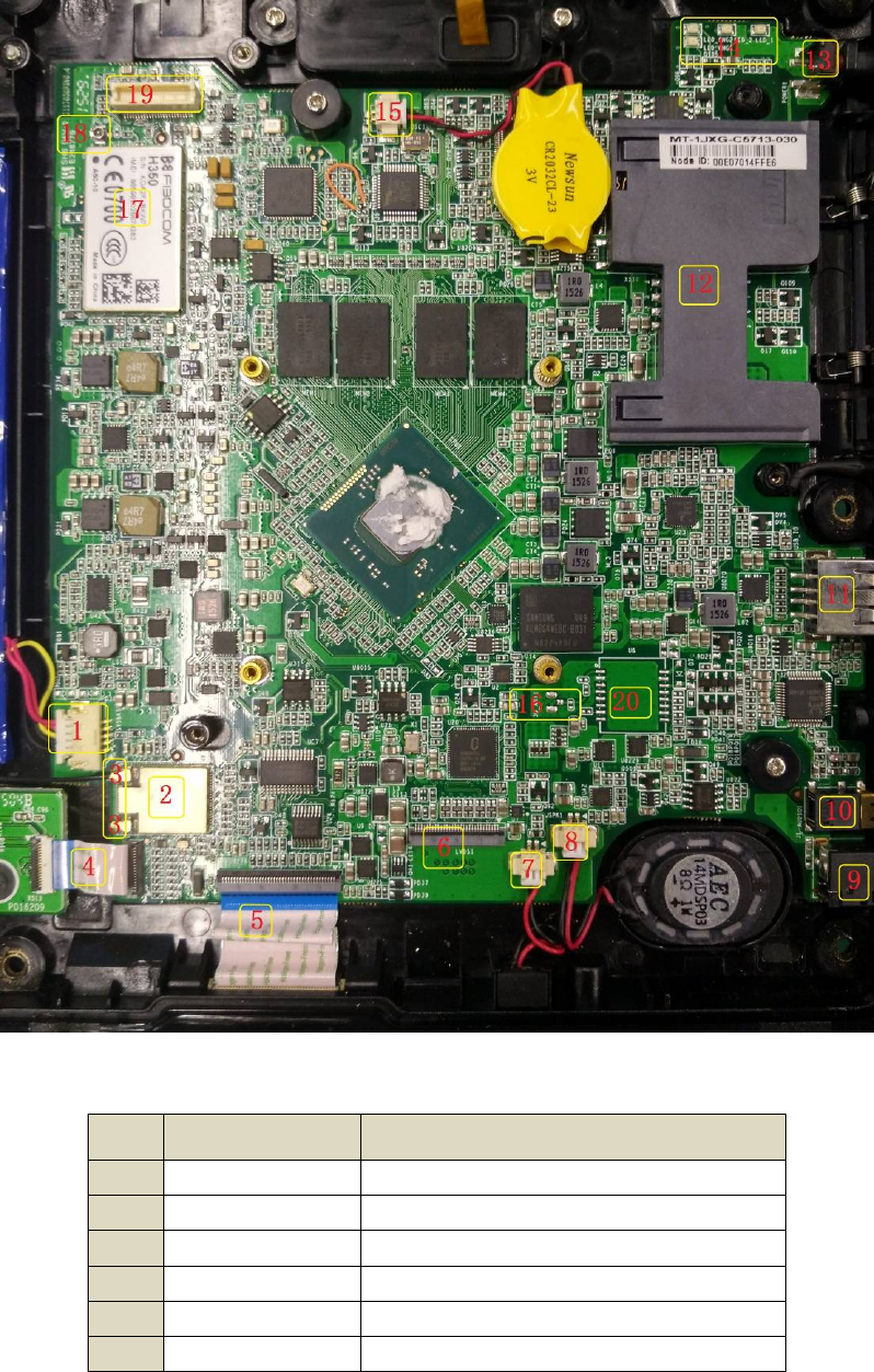
01. MotherboardLayout
02. MotherboardModulesandFunctions
Num Module Function Description
1 Li-battery Li-battery connector
2 WIFI+BT Wifi+BT module
3 WIFI+BT Wifi+BT antenna connector
4 micro SD+SIM Micro SD+SIM board connector
5 Pogo Pogo connector
6 LCD+TP LCD+TP connector
7 MIC MIC connector
8 Speaker Speaker connector
9 DC Jack DC Jack connector
10 Audio 3.5mm stereo headphone
11 USB USB2.0 connector
12 IC IC card acceptor
13 Button Power button
14 LED LED Indicators
15 BIOS-battery
connector BIOS-battery connector
16 GPS GPS antenna connector
17 3G 3G antenna connector
18 3G 3G module
19 Camera/card
reader Camera/Card reader board connector
20 GPS GPS module
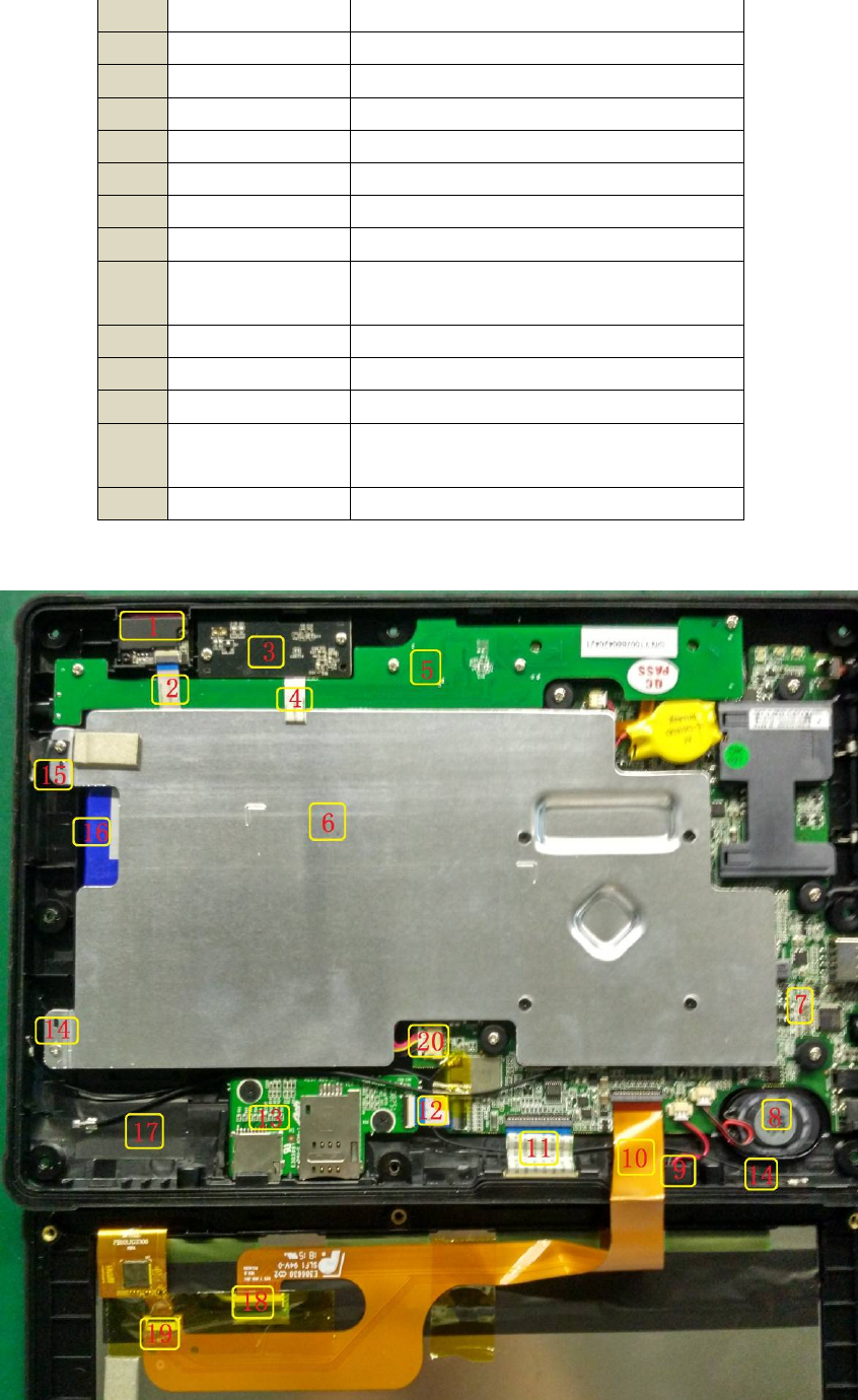
03. ProductLayout

02. Modules&Functions
Num Module Function Description
1 Scanner 1D Barcode Scanner
2 FFC Scanner FFC cable
3 PCB Camera Board PCB
4 FFC Camera Board FFC cable
5 PCB MSR & RFID Board PCB
6 Aluminum plate Aluminum Thermal Spreader
7 PCB Mother Board PCB
8 Speaker 8 Ohm, 1 Watt Speaker
9 MIC MIC
10 FPC LCD Screen and TP FPC cable
11 FFC Pogo FFC cable
12 FFC micro-SD/3G FFC cable
13 PCB micro-SD/3G Board PCB
14 Antenna Wifi+BT antenna
15 Antenna 3G antenna
16 Li-battery 4000mAh 7.4V Li-battery
17 Antenna GPS antenna(optional)
18 LCD LCD Connector
19 Touch Panel Touch Panel Connector
20 FFC Li-battery FFC cable