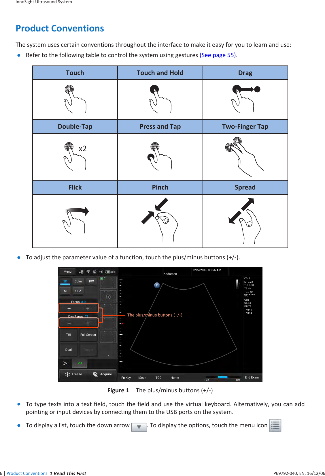
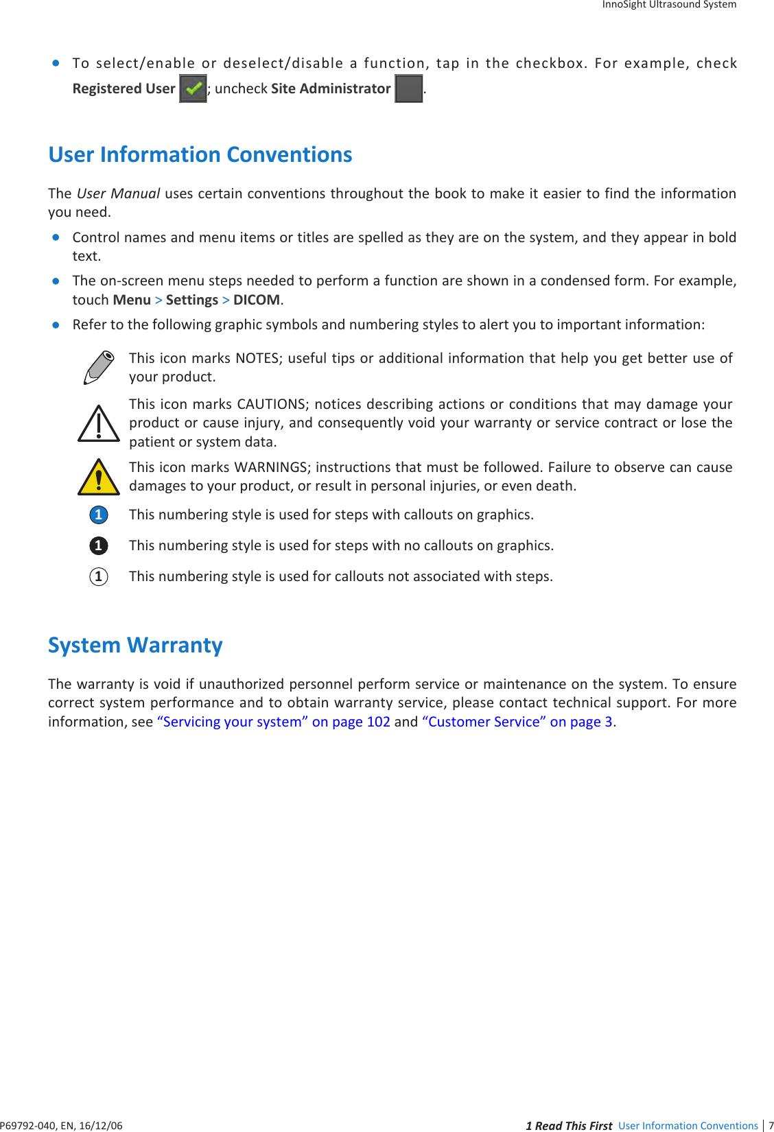
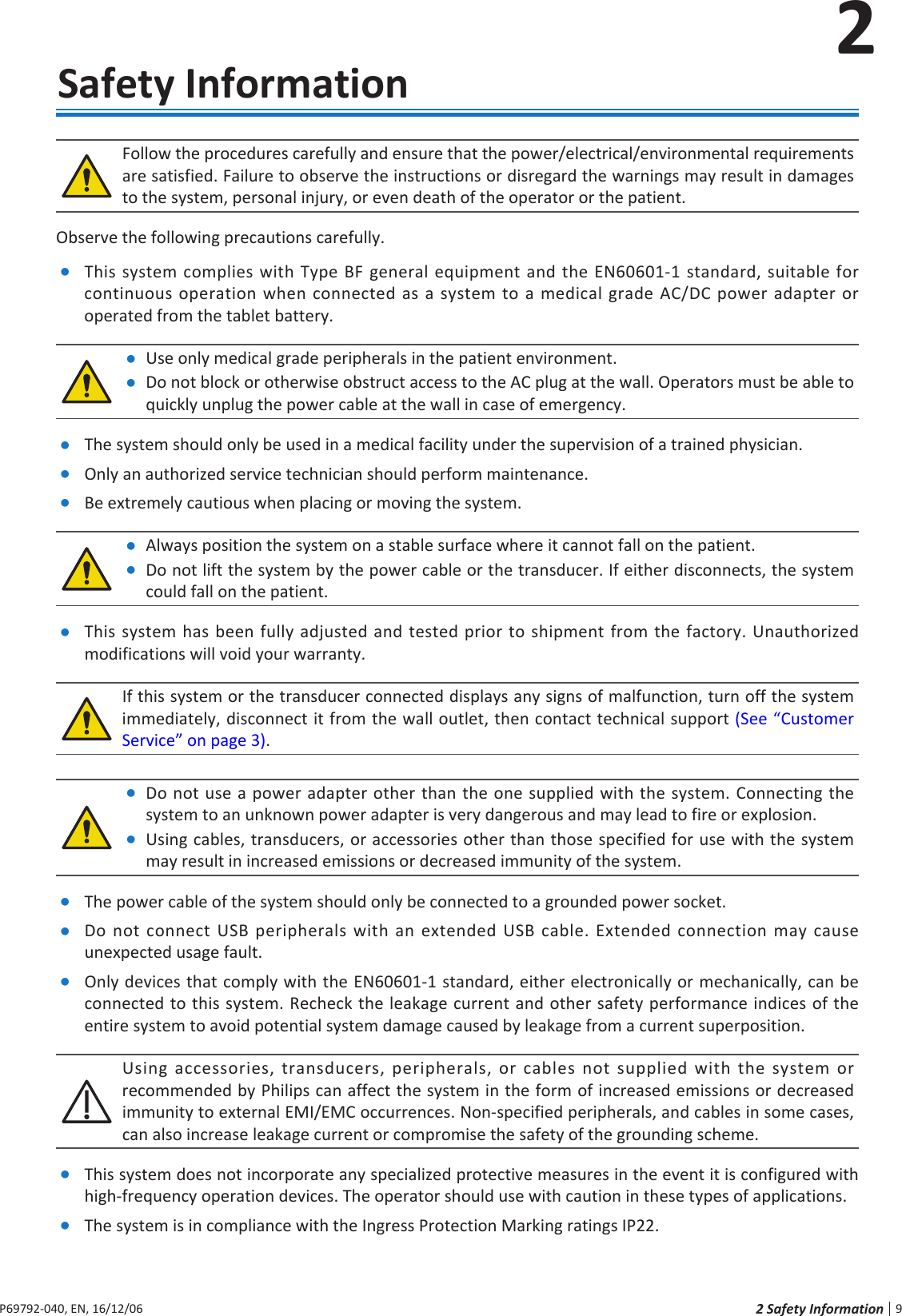
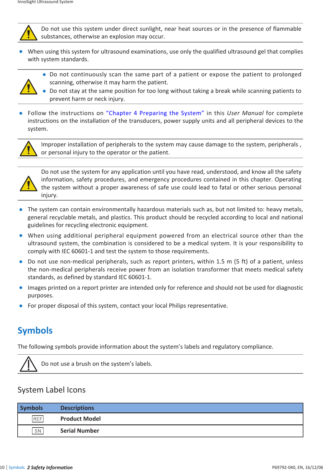
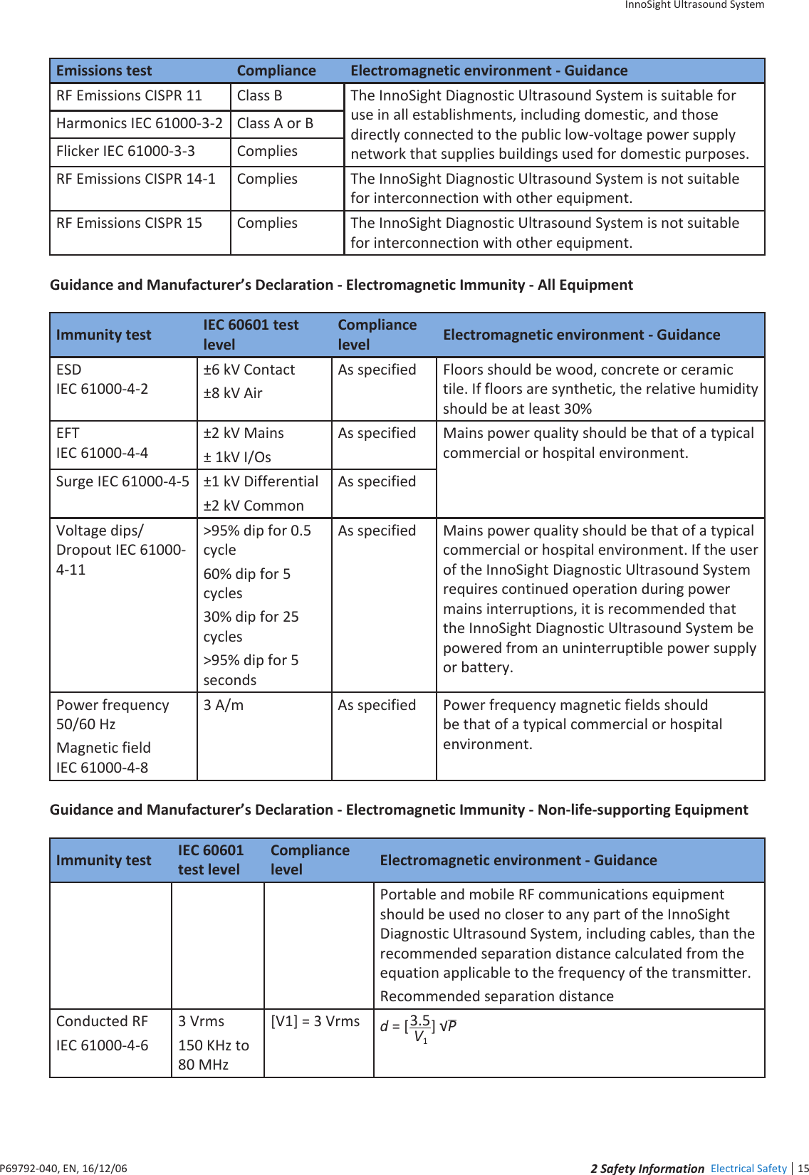
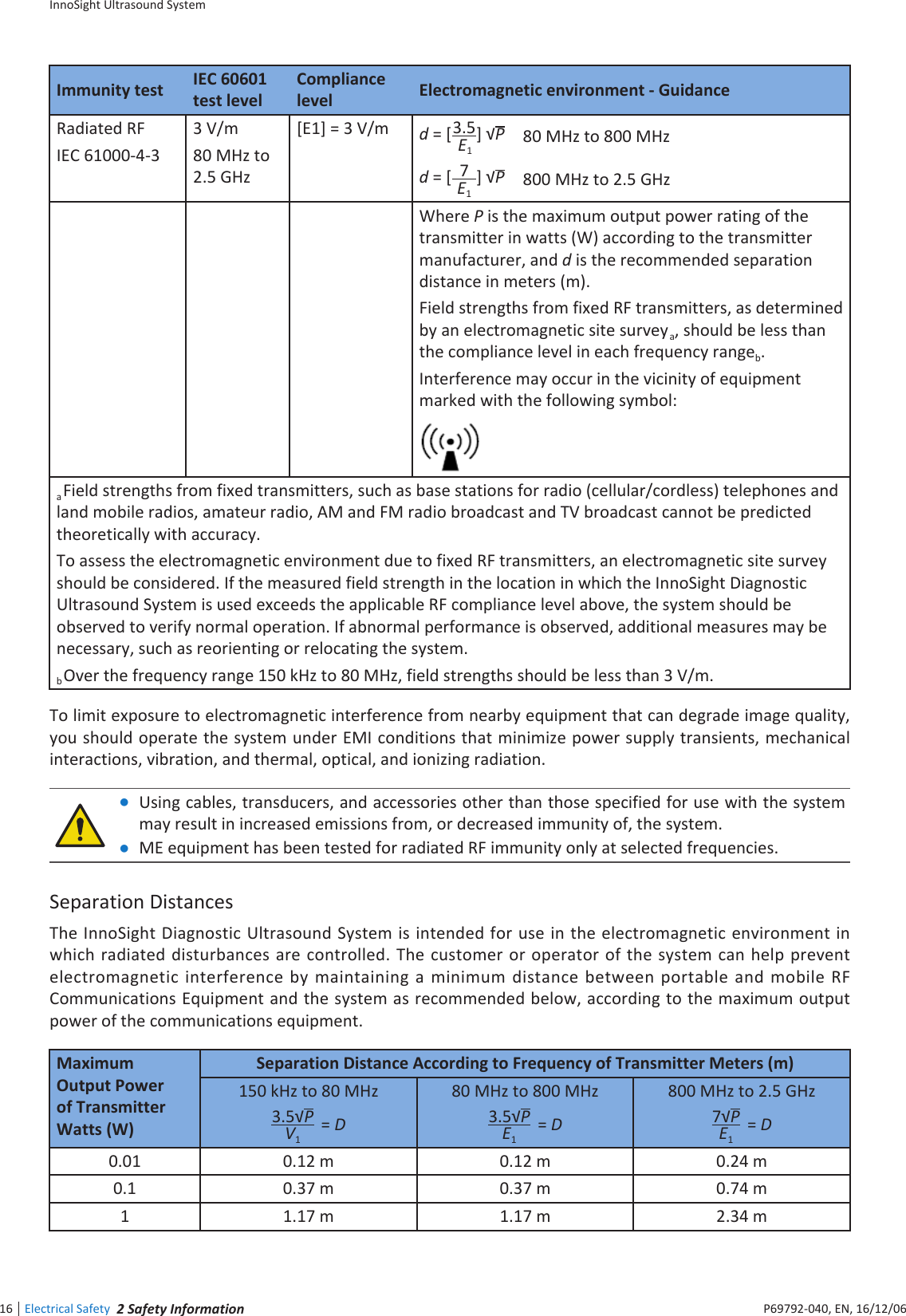
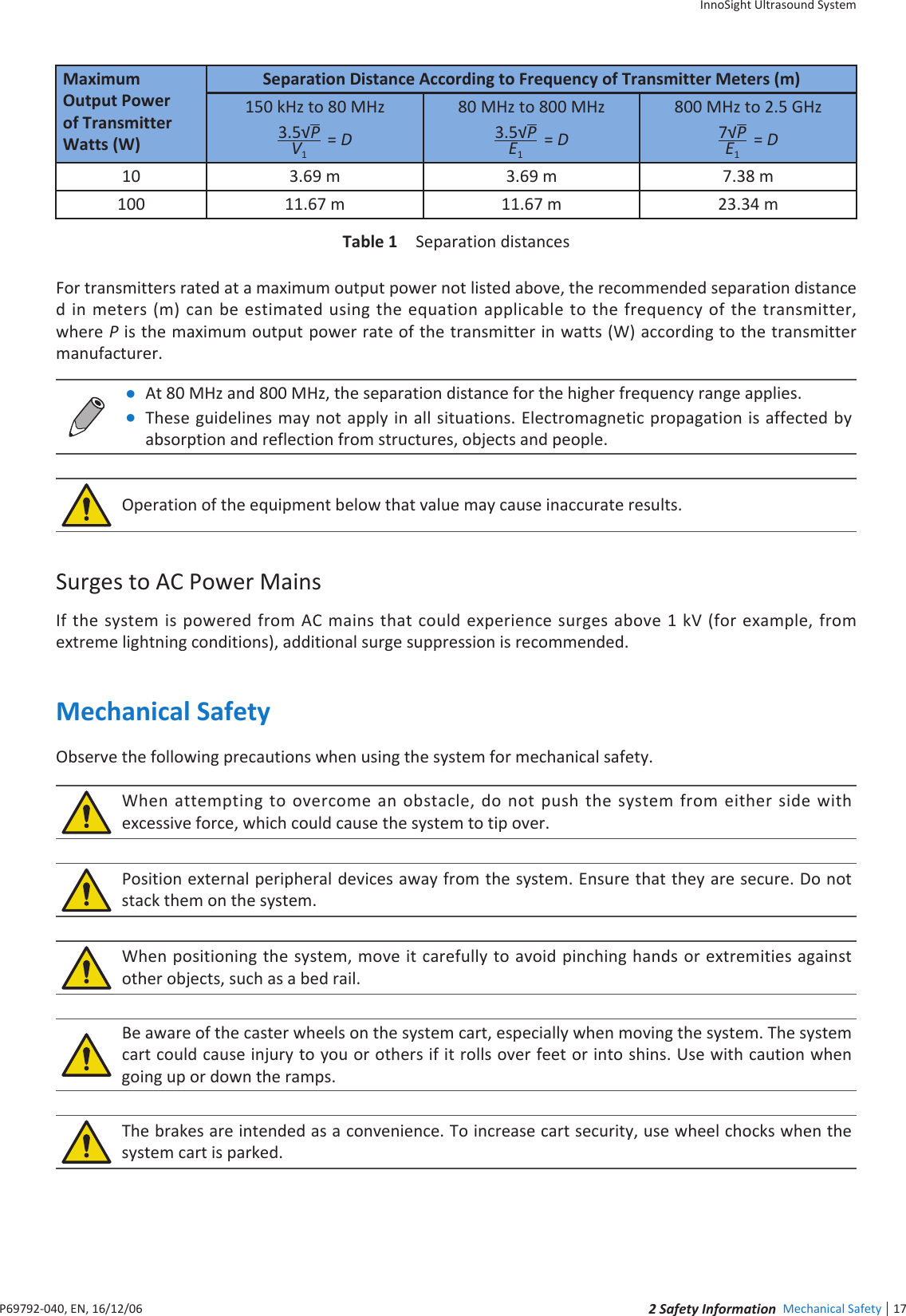
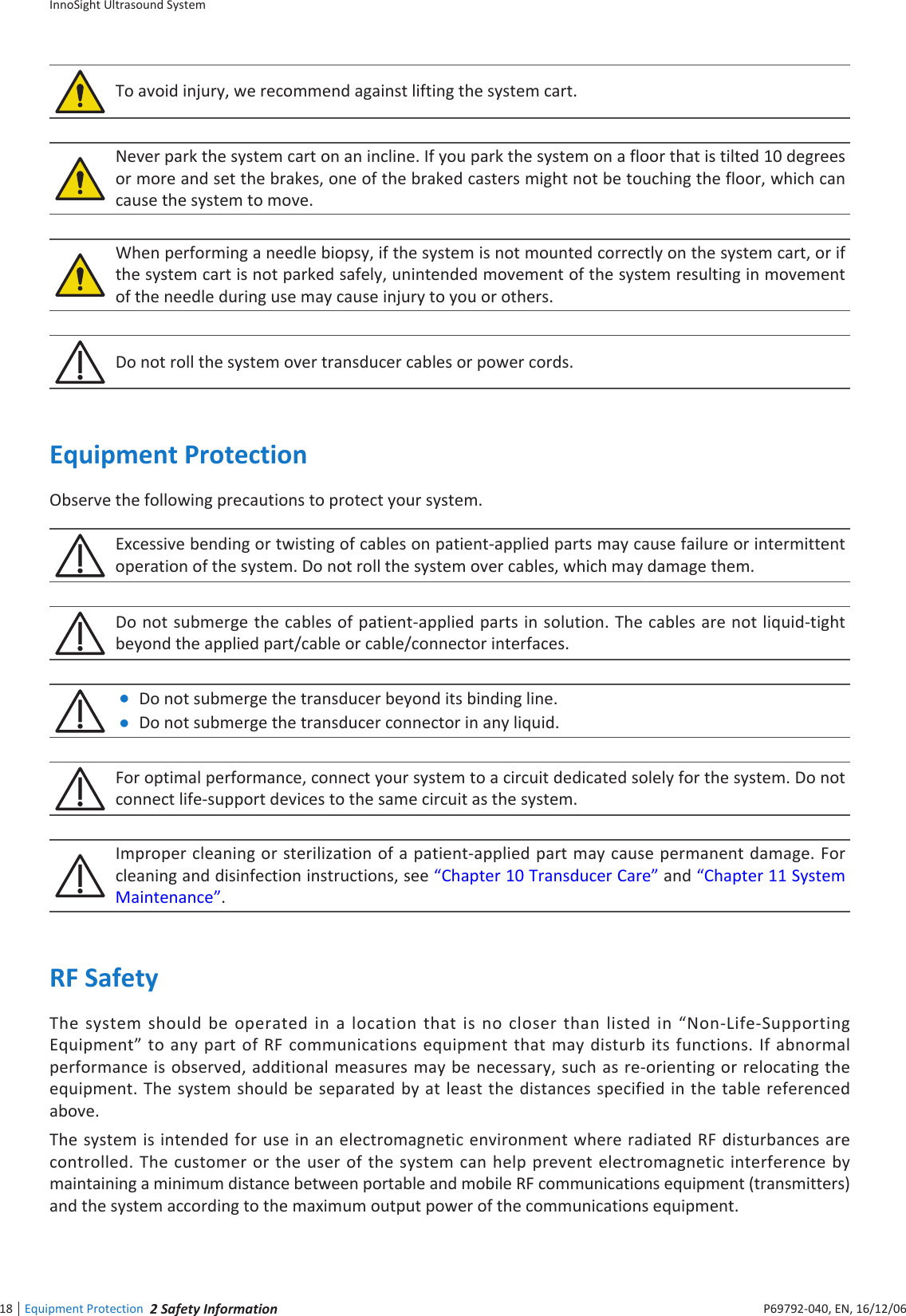
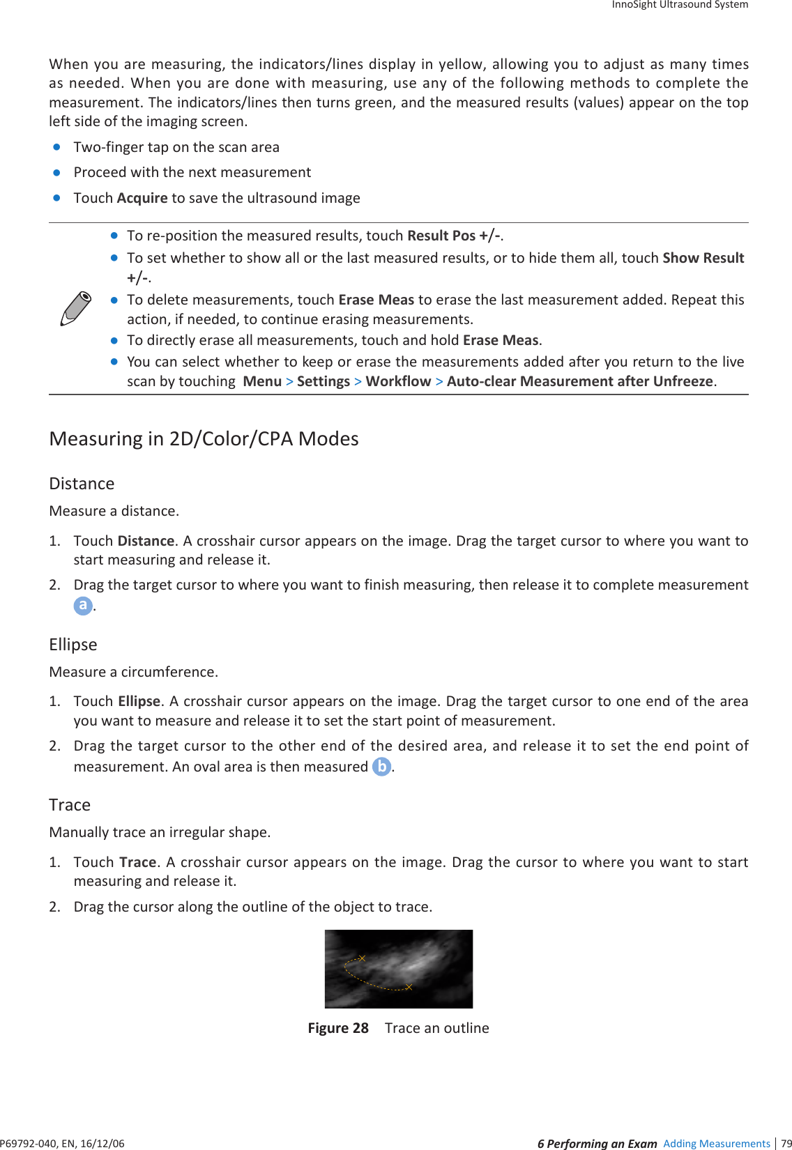
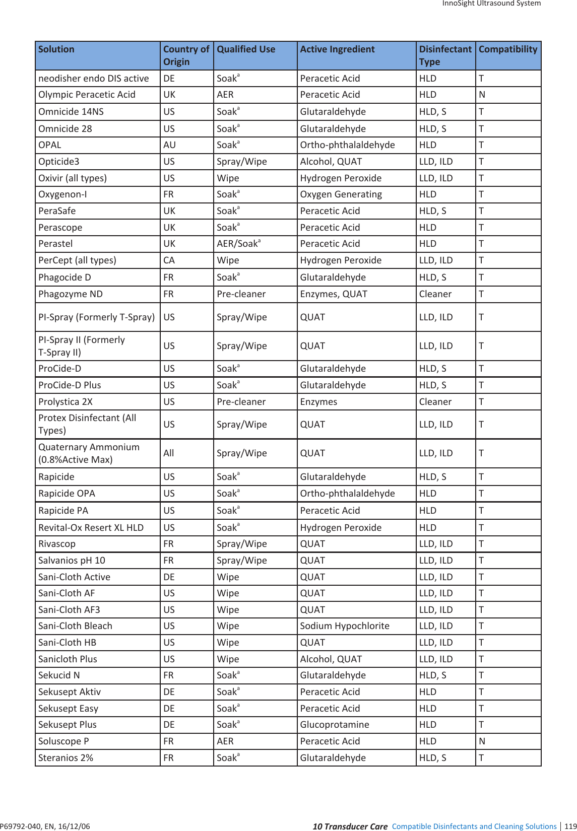
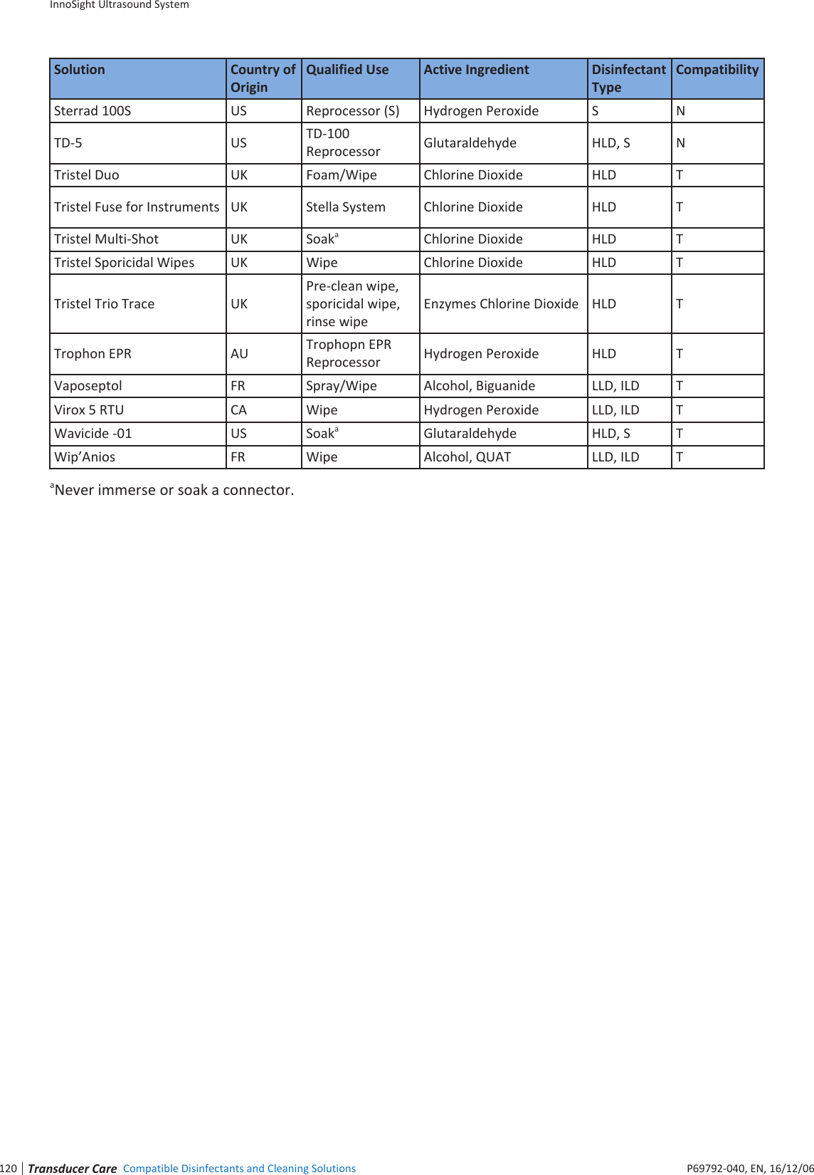
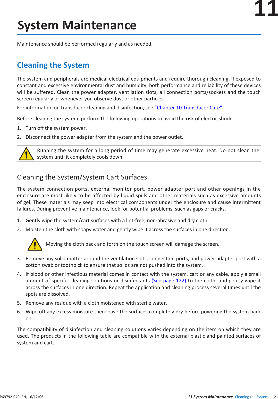
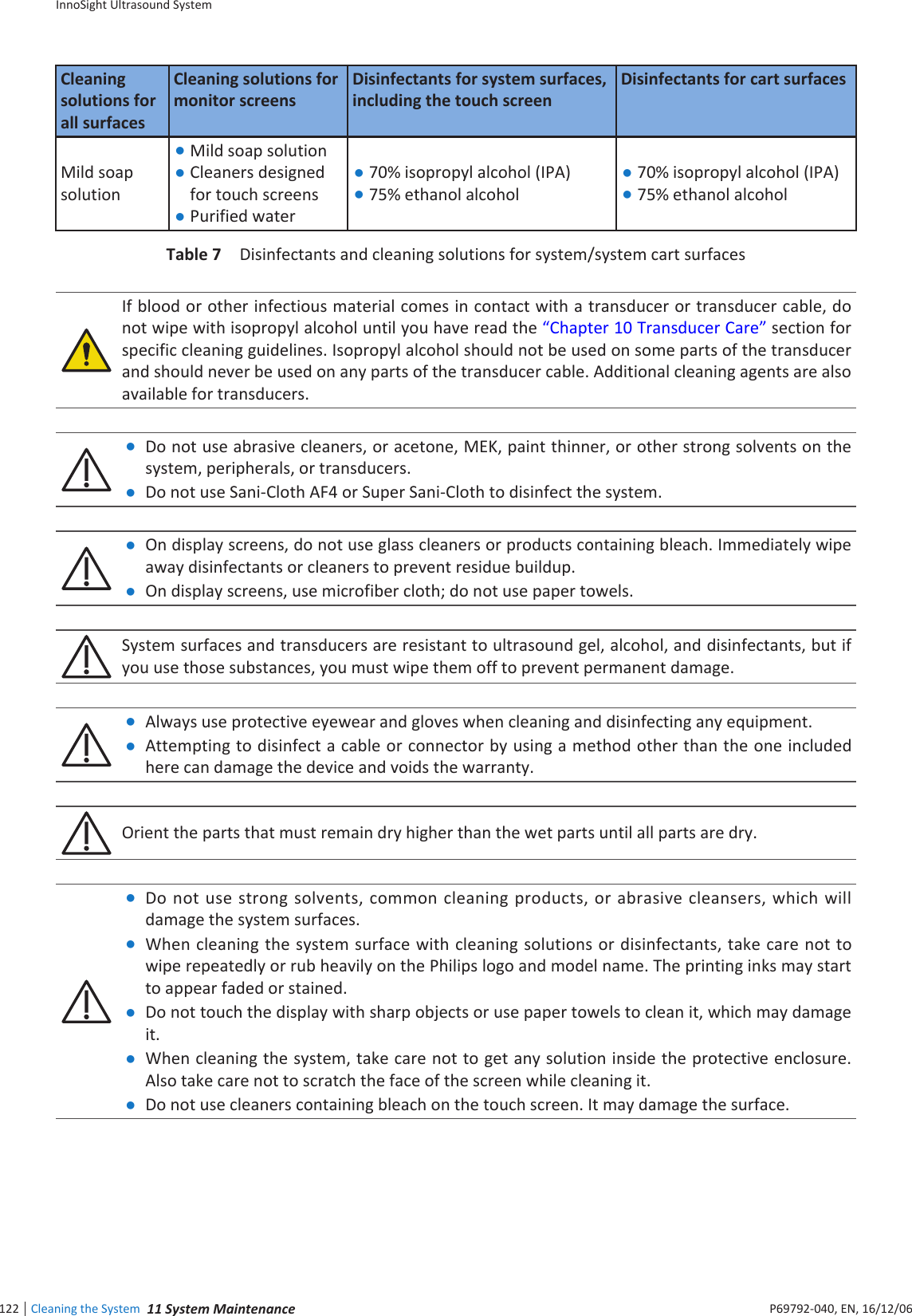
Qisda APOLLO Diagnostic Ultrasound System User Manual

Qisda Corporation Diagnostic Ultrasound System Users Manual

Users Manual

InnoSightDiagnostic Ultrasound SystemUser Manual
iii  ContentsInnoSight Ultrasound SystemP69792-040, EN, 16/12/06ContentsChapter 1  Read This First ................................................................................................ 1Intended Audience ............................................................................................................................................ 1Intended Use ..................................................................................................................................................... 1Warnings ........................................................................................................................................................... 2Upgrades and Updates ...................................................................................................................................... 2Supplies and Accessories ................................................................................................................................... 3Customer Service .............................................................................................................................................. 3Recycling, Reuse, and Disposal .......................................................................................................................... 3Passing Your System to Another User ......................................................................................................... 4Final Disposal of Your System ..................................................................................................................... 4Perchlorate Material ................................................................................................................................... 4Discarding the Tablet and Batteries ............................................................................................................ 4Equipment List ................................................................................................................................................... 5User Information Components.......................................................................................................................... 5Product Conventions ......................................................................................................................................... 6User Information Conventions .......................................................................................................................... 7System Warranty ............................................................................................................................................... 7Chapter 2  Safety Information .......................................................................................... 9Symbols ........................................................................................................................................................... 10System Label Icons .................................................................................................................................... 10System Button ........................................................................................................................................... 11Shipping Label Icons .................................................................................................................................. 12Electrical Safety ............................................................................................................................................... 12Battery Usage/Disposal ............................................................................................................................. 14Electrical Fast Transients (EFT) .................................................................................................................. 14Electromagnetic Interference (EMI) .......................................................................................................... 14Surges to AC Power Mains ........................................................................................................................ 17Mechanical Safety ........................................................................................................................................... 17Equipment Protection ..................................................................................................................................... 18RF Safety .......................................................................................................................................................... 18Biological Safety .............................................................................................................................................. 19Heating ...................................................................................................................................................... 19Cavitation .................................................................................................................................................. 19Safe Scanning Guideline ............................................................................................................................ 19FDA Medical Alert on Latex ....................................................................................................................... 21Operator Safety ............................................................................................................................................... 21Repetitive Strain Injury.............................................................................................................................. 22Philips Transducers ................................................................................................................................... 22Glutaraldehyde Exposure .......................................................................................................................... 22Infection Control ....................................................................................................................................... 22Waterproof and Dustproof Ratings ................................................................................................................. 23Understanding the MI/TI Display .................................................................................................................... 23
InnoSight Ultrasound System  Contentsiv P69792-040, EN, 16/12/06TI ............................................................................................................................................................... 25MI .............................................................................................................................................................. 25Display and Report in Different Modes ..................................................................................................... 26Operator Control Features ........................................................................................................................ 26Transducer Surface Temperature Rise ............................................................................................................ 26Chapter 3  Overview .......................................................................................................27System Capabilities ......................................................................................................................................... 27Imaging ...................................................................................................................................................... 27Transducer Types ...................................................................................................................................... 27Measurements .......................................................................................................................................... 27Calculations ............................................................................................................................................... 28Image Acquisition and Review .................................................................................................................. 28Patient Data Protection ............................................................................................................................. 28Connectivity .............................................................................................................................................. 28Peripherals (optional) ................................................................................................................................ 28Service ....................................................................................................................................................... 28System Overview ............................................................................................................................................. 29Front and Side Views ................................................................................................................................. 29Rear and Top/Bottom Views ..................................................................................................................... 30Transducer Overview ...................................................................................................................................... 31Clinical Applications and Transducers ....................................................................................................... 31System Cart Overview ..................................................................................................................................... 32Front View ................................................................................................................................................. 32Rear View .................................................................................................................................................. 33Indications for Use and Supporting Transducers ............................................................................................ 34Chapter 4  Preparing the System .....................................................................................39Inserting a microSD Card ................................................................................................................................. 39Using the Stand ............................................................................................................................................... 40Charging the System ........................................................................................................................................ 41Connecting the Transducer ............................................................................................................................. 42Removing the Transducer ............................................................................................................................... 42Using the System On The Go ........................................................................................................................... 43Using the Wheel Brakes .................................................................................................................................. 44Placing the Transducer Holder ........................................................................................................................ 44Mounting the System to the System Cart ....................................................................................................... 45Adjusting the System Cart Height ................................................................................................................... 46Connecting an External Printer ....................................................................................................................... 47Tilting the System ............................................................................................................................................ 48Unmounting the System From the System Cart .............................................................................................. 49Moving the System .......................................................................................................................................... 49Outputting the System Display to an HDMI-Enabled TV or Monitor .............................................................. 50Supported External Printers ............................................................................................................................ 50Chapter 5  Using the System ...........................................................................................51
v  ContentsInnoSight Ultrasound SystemP69792-040, EN, 16/12/06Turning On/Off the System ............................................................................................................................. 51Logging Into the System .................................................................................................................................. 51Creating a New Administrator Account .................................................................................................... 52Adding a New User Account ...................................................................................................................... 52Switching Users ......................................................................................................................................... 52Managing User Settings ............................................................................................................................ 53Launching the Main Screen ............................................................................................................................. 53Setting the System Time and Date .................................................................................................................. 54Controlling the System .................................................................................................................................... 55Gestures for Controlling the Real-time/Frozen Imaging Screens .............................................................. 55Gestures for Controlling the Real-time Imaging Screen ............................................................................ 56Gestures for Controlling the Frozen Imaging Screen ................................................................................ 56Setting the System Language .......................................................................................................................... 56Identifying the Main Screen Layout ................................................................................................................ 57System Menu Screen ................................................................................................................................. 57Imaging Screen (Real-time) ....................................................................................................................... 58Imaging Screen (Frozen) ............................................................................................................................ 60Switching the Control Panel Pages .................................................................................................................. 62Managing the System Power ........................................................................................................................... 63Sleep Mode ............................................................................................................................................... 64Managing Disk Space ....................................................................................................................................... 64Network Configuration .................................................................................................................................... 65Connecting the System to the Network by Ethernet ................................................................................ 65Connecting the System to the Wireless Network ..................................................................................... 65Connecting the System to a Bluetooth Device .......................................................................................... 66DICOM Configuration ...................................................................................................................................... 66Modality Interface ..................................................................................................................................... 66Adding Servers .......................................................................................................................................... 66Local Host .................................................................................................................................................. 67Managing Outgoing Queue ....................................................................................................................... 67Chapter 6  Performing an Exam ......................................................................................69Starting a New Exam ....................................................................................................................................... 69Adding a New Patient ...................................................................................................................................... 70Updating Patient Information ................................................................................................................... 70Loading a Worklist ........................................................................................................................................... 71Selecting a Preset ............................................................................................................................................ 72Customizing a Preset ................................................................................................................................. 72Modifying a Preset .................................................................................................................................... 72Managing Presets ...................................................................................................................................... 72Exporting and Importing Customized Presets ........................................................................................... 73Setting the Transducer Orientation ................................................................................................................. 73Selecting/Switching a Scan Mode ................................................................................................................... 73Adjusting the Displayed Image ........................................................................................................................ 73Enlarging an Area of the Image ................................................................................................................. 73Splitting the Imaging Screen ..................................................................................................................... 74
InnoSight Ultrasound System  Contentsvi P69792-040, EN, 16/12/06Freezing an Image ........................................................................................................................................... 76Adding Annotations ......................................................................................................................................... 76Arrow ........................................................................................................................................................ 76Label .......................................................................................................................................................... 77Body Mark ................................................................................................................................................. 77Adding Measurements .................................................................................................................................... 78Measuring in 2D/Color/CPA Modes .......................................................................................................... 79Measuring in M-Mode .............................................................................................................................. 80Measuring in Spectral Doppler Mode ....................................................................................................... 81Saving and Printing the Image ......................................................................................................................... 82Saving an Image Loop ................................................................................................................................ 83Saving an Image ........................................................................................................................................ 83Printing an Image ...................................................................................................................................... 83Reviewing the Image ....................................................................................................................................... 83Performing Multiple Selections ................................................................................................................. 84Comparing Images .................................................................................................................................... 84Generating a Report .................................................................................................................................. 85Exporting the Exam ......................................................................................................................................... 85Managing the Exam List .................................................................................................................................. 86Ending the Exam .............................................................................................................................................. 87Chapter 7  Using Image Controls .....................................................................................892D Mode Image Controls ................................................................................................................................ 89Overview ................................................................................................................................................... 89Adjusting Gain ........................................................................................................................................... 89Adjusting Frequency.................................................................................................................................. 89Adjusting Time Gain Compensation (TGC) ................................................................................................ 90Adjusting the Scan Depth .......................................................................................................................... 90Adjusting the Focus Depth, Focal Zone and Focal span ............................................................................ 90Adjusting Dynamic Range .......................................................................................................................... 90Using Tissue Harmonic Imaging (THI) ........................................................................................................ 90Adjusting Persistence ................................................................................................................................ 90Adjusting Sharpness and Smoothing ......................................................................................................... 90Adjusting Gray Map ................................................................................................................................... 90Adjusting Chroma Map ............................................................................................................................. 91Adjusting Steer Angle ................................................................................................................................ 91Adjusting the Sector Width and Position .................................................................................................. 91Adjusting Power ........................................................................................................................................ 91Using Trapezoidal Imaging ........................................................................................................................ 91Adjusting Density ...................................................................................................................................... 91Using Compound Imaging ......................................................................................................................... 91Using ENV (Enhanced Needle Visualization) ............................................................................................. 91Color/CPA Mode Image Controls .................................................................................................................... 92Overview ................................................................................................................................................... 92Adjusting Pulse Repetition Frequency (PRF) ............................................................................................. 93Adjusting Wall Filter (WF) ......................................................................................................................... 93Applying the Smoothing Filter ................................................................................................................... 93
vii  ContentsInnoSight Ultrasound SystemP69792-040, EN, 16/12/06Adjusting the Color Priority ....................................................................................................................... 93Inverting the Color Display ........................................................................................................................ 94Using Directional Power ............................................................................................................................ 94M-Mode Image Controls ................................................................................................................................. 94Overview ................................................................................................................................................... 94Using Steer M ............................................................................................................................................ 95Adjusting Sweep Speed ............................................................................................................................. 95Selecting M Process .................................................................................................................................. 95Inverting the M-Mode Trace Display ........................................................................................................ 95Spectral Doppler Mode Image Controls .......................................................................................................... 95Overview ................................................................................................................................................... 95Adjusting Baseline ..................................................................................................................................... 96Adjusting Sample Volume (SV) Size ........................................................................................................... 96Adjusting Correction Angle ....................................................................................................................... 97Updating the 2D Display ............................................................................................................................ 97Chapter 8  System Customization and Service .................................................................99Customizing Your System ................................................................................................................................ 99General ...................................................................................................................................................... 99Preset ........................................................................................................................................................ 99Patient ....................................................................................................................................................... 99Exam .......................................................................................................................................................... 99Workflow ................................................................................................................................................... 99Imaging .................................................................................................................................................... 100Annotation .............................................................................................................................................. 100Body Mark ............................................................................................................................................... 101Measurement .......................................................................................................................................... 101Report ..................................................................................................................................................... 101DICOM ..................................................................................................................................................... 101Networking .............................................................................................................................................. 101Print ......................................................................................................................................................... 102Configuring Security Policies ......................................................................................................................... 102Security Policies....................................................................................................................................... 102User Management .................................................................................................................................. 102Servicing your system .................................................................................................................................... 102Reinstalling Software .............................................................................................................................. 103Checking the Software Version ............................................................................................................... 103Checking the System’s Serial Number ..................................................................................................... 103Checking the Tablet’s Serial Number ...................................................................................................... 103Checking the License Status .................................................................................................................... 103Resetting User Settings ........................................................................................................................... 104Backing Up System Settings and Patient Data ........................................................................................ 104Restoring System Settings and Patient Data ........................................................................................... 104Resetting Your System ............................................................................................................................ 104Testing the System .................................................................................................................................. 104Exporting System Logs ............................................................................................................................ 105Reading the User Manual ........................................................................................................................ 105
InnoSight Ultrasound System  Contentsviii P69792-040, EN, 16/12/06Chapter 9  Transducers .................................................................................................107Transducer Maintenance .............................................................................................................................. 107Acoustic artifacts ........................................................................................................................................... 107Transducer Covers ......................................................................................................................................... 109Transducer Storage ....................................................................................................................................... 110Storage for Transport .............................................................................................................................. 110Daily and Long-Term Storage .................................................................................................................. 110Chapter 10  Transducer Care .........................................................................................111Transducer Care and Operator Safety ........................................................................................................... 111Latex Product Alert ................................................................................................................................. 113Inspecting the Transducer ............................................................................................................................. 113Transducer Care Methods ............................................................................................................................. 113Transducer and Cable Cleaning ..................................................................................................................... 113Cleaning Instructions ............................................................................................................................... 114Low-Level Disinfecting of Transducers .......................................................................................................... 114High-Level Disinfecting of Transducers ......................................................................................................... 115Ultrasound Transmission Gels ....................................................................................................................... 115Compatible Disinfectants and Cleaning Solutions ......................................................................................... 116Chapter 11  System Maintenance .................................................................................121Cleaning the System ...................................................................................................................................... 121Cleaning the System/System Cart Surfaces ............................................................................................. 121Cleaning the Power Adapter ................................................................................................................... 123Troubleshooting ............................................................................................................................................ 123Chapter 12  Appendix ...................................................................................................127Appendix A: Specifications ............................................................................................................................ 127System ..................................................................................................................................................... 127Battery ..................................................................................................................................................... 128Transducer .............................................................................................................................................. 129Power Adapter ........................................................................................................................................ 129Appendix B: Connectivity and Security ......................................................................................................... 130Introduction ............................................................................................................................................ 130Specifications .......................................................................................................................................... 130Security ................................................................................................................................................... 130Information Flow ..................................................................................................................................... 131IT Network Failure Recovery Measures .................................................................................................. 131Appendix C: System Acoustic Output Default Tables .................................................................................... 133C6-2 Transducer ...................................................................................................................................... 133L12-4 Transducer ..................................................................................................................................... 135S4-2 Transducer ...................................................................................................................................... 137C9-4v Transducer .................................................................................................................................... 138Appendix D: Acoustic Output Reporting Tables for Track 3 .......................................................................... 139Definition of Terms Used in Acoustic Output Tables .............................................................................. 139Acoustic Output Tables for InnoSight Transducers ................................................................................. 141Appendix D: FCC Statement .......................................................................................................................... 169
11 edii Intended Audience1P6992-4, EN, 16/12/61  Read This FirstThe InnoSight Diagnostic Ultrasound System (hereinafter called system) is an easy-to-use, portable ultrasound imaging instrument intended for use by a qualified operator for ultrasound evaluation and clinical analysisThe User Manual provides important procedures and information on how to operate the system and service the system correctly and safely Before attempting to operate the system, read this manual and strictly observe all warnings and cautions Pay extra attention to the information from Chapter 2 Safety InformationThis manual aims to provide the most updated and accurate information to customers and thus all contents may be modified from time to time without prior notice No part of this publication may be reproduced, transmitted, transcribed, stored in a retrieval system or translated into any language or computer language, in any form or by any means, electronic, mechanical, magnetic, optical, chemical or manual We make no representations or warranties, either expressed or implied, with respect to the contents hereof and specifically disclaims any warranties, merchantability or fitness for any particular purpose Further, we reserve the right to revise this publication and to make changes from time to time in the contents hereof without obligation to notify any person of such revision or changesChroma, Color Power Angio, High Q, SonoCT, and RES are trademarks of oninklijke Philips NVNon-Philips product names may be trademarks of their respective ownersDistributed by Philips Ultrasound, Inc.221 Bothell Everett Hwy, Bothell, WA 921-431 USAManufactured by Qisda CorporationNo1, Shan-Ying Road, Shan-Ting Li, Gueishan Dist, Taoyuan City, Taiwan, ROCIntended AudienceThis document  is intended  for sonographers,  physicians, and  biomedical engineers  who  operate and maintain the system and are familiar with ultrasound techniquesIntended UseThe system is designed for use as a diagnostic ultrasound imaging tool and fluid flow analysis of the human body The system shall provide the ability for gathering clinically acceptable images and ultrasound data for the clinical applications and anatomies The clinical environments where the system can be used include clinics, hospitals, and clinical point-of-care for diagnosis of patientsThe system is intended to be installed, used, and operated only in accordance with the safety procedures and operating instructions given in the system user information, and only for the purposes for which it was designedThe system should only be operated by someone who has received proper training in the use and operation of an ultrasound system This system produces images derived from sound echoes those images must be interpreted by a qualified medical professional This system in no way interprets these images or provides a medical diagnosis of the patient being examined
InnoSight Ultrasound SystemWarnings 1 edii2P6992-4, EN, 16/12/6Do not use the system for purposes other than those intended and expressly stated above Do not misuse the system, and do not use or operate the system incorrectlyInstallation, use, and operation of the system are subject to the law in the jurisdictions in which it is used Install, use, and operate the system only in such ways that do not conflict with applicable laws or regulations, which have the force of law Use of the system for purposes other than those intended and expressly stated here, as well as incorrect use or operation, may relieve us or our agents from all or some responsibilities for resultant noncompliance, damage, or injurySystem users are responsible for image quality and diagnosis Inspect the data that is being used for the analysis and diagnosis, and ensure that the data is sufficient both spatially and temporally for the measurement approach being usedWarningsBefore using the system, read these warnings and Chapter 2 Safety InformationDo not attempt to disassemble or modify the system There are no user serviceable parts inside this system Necessary modifications must be made only by the manufacturer or its designated agentsDo not allow any liquid to get inside this system Water and moisture may cause short-circuit to the electronic components and lead to malfunctionsDo not drop or apply shock/vibration to this system Strong impacts may damage the components insideDo not cut, bend, modify, place heavy objects, or step on the cable of the power adapter Otherwise the external insulation may be damaged and result in short-circuit or fireDo not use this system near strong electromagnetic sources, such as a microwave oven The electromagnetic interference may cause this system to malfunctionTo avoid electrical shock, use only supplied power cords and connect only to properly grounded wall (wall/mains) outletsThe system should not be used adjacent to or stacked with other equipment If adjacent or stacked use is necessary, the system should be observed to verify normal operation in the configuration in which it will be usedUpgrades and UpdatesPhilips is committed to innovation and continued improvement Upgrades may be announced that consist of hardware or software improvements Updated user information will accompany those upgrades
31 edii Supplies and AccessoriesInnoSight Ultrasound SystemP6992-4, EN, 16/12/6Supplies and AccessoriesTo order transducer covers and other supplies and accessories, contact CIVCO Medical Solutions:CIVCO Medical Solutions12 First Street South, alona, IA 224 99Telephone:  44 641 (USA and Canada), 1 319 24 6 (International)Fax:  329 242 (USA and Canada), 1 319 24 666 (International)E-mail: infocivcocomInternet: wwwcivcocomTo order the items listed in the following table, see the referenced information and contact your Philips representativeSystem AccessoriesItem Additional InformationPrinters See Supported External Printers on page Transducers See Clinical Applications and Transducers on page 31Customer ServiceCustomer service representatives are available worldwide to answer questions and to provide maintenance and service Please contact your local Philips representative for assistance You can also contact the following office for referral to a customer service representative, or visit the Philips Contact Us website:wwwhealthcarephilipscom/main/about/officelocator/indexwpdPhilips Ultrasound Headquarters221 Bothell Everett Hwy, Bothell, WA 921-431, USA-22-93Recycling, Reuse, and DisposalPhilips is concerned with helping protect the natural environment and helping ensure continued safe and effective use of this system through proper support, maintenance, and training Philips designs and manufactures equipment in compliance with relevant guidelines for environmental protection As long as the equipment is properly operated and maintained, it presents no risk to the environment However, the equipment may contain materials that could be harmful to the environment if disposed of incorrectly Use of such materials is essential for the implementation of certain functions and for meeting certain statutory and other requirementsThe European Union Directive on Waste Electrical and Electronic Equipment (WEEE) requires producers of electrical and electronic equipment to provide reuse and treatment information for each product This product complies with WEEE
InnoSight Ultrasound SystemRecycling, Reuse, and Disposal 1 edii4P6992-4, EN, 16/12/6Passing Your System to Another UserIf you pass this system to another user who will use the system for its intended purpose, then pass it on in its complete state Particularly, ensure  that all the product-support documentation, including all instructions for use, are passed on to the new user Make the new user aware of the support services that Philips provides for installing, commissioning, and maintaining the system, and for comprehensive operator training Existing users must remember that passing on medical electrical equipment to new users may present serious technical, medical, privacy, and legal risks The original user may remain liable, even if the equipment is given awayPhilips strongly advises you to seek advice from your local Philips representative before agreeing to pass on any equipmentAfter you pass the system to a new user, you might still receive important safety-related information, such as bulletins and field change orders In many jurisdictions the original owner has a clear duty to communicate such safety-related information to new users If you are unable or unprepared to do this, inform Philips about the new user, so that Philips can provide the new user with safety-related informationFinal Disposal of Your SystemFinal disposal is when you dispose of the system in such a way that it can no longer be used for its intended purposesDo not dispose of this system (or any parts of it) with industrial or domestic waste The system may contain materials such as lead, tungsten, or oil, or other hazardous substances that can cause serious environmental pollution The system also contains privacy-sensitive information, which should be properly removed (scrubbed) Philips advises you to contact your Philips service organization before disposing of this systemPerchlorate MaterialIn this system, perchlorate material is present in lithium coin cells or batteries Special handling may apply to those items For more information, see this website:wwwdtsccagov/hazardous waste/perchlorateDiscarding the Tablet and BatteriesThe tablet and internal batteries should be discarded in an environmentally safe manner Properly dispose of batteries according to local regulationsDo not disassemble, puncture, or incinerate batteries Be careful not to short the battery terminals, because that could result in a fire hazardUse caution when handling, using, and testing the batteries Do not short circuit, crush, drop, mutilate, puncture, apply reverse polarity, expose to high temperatures, or disassemble Misuse or abuse could cause physical injury
1 edii Equipment ListInnoSight Ultrasound SystemP6992-4, EN, 16/12/6If electrolyte leakage occurs, wash your skin with large amounts of water to prevent skin irritation and inflammationEquipment ListCheck the sales package for the following items If any item is missing or damaged, contact your place of purchase immediately Philips Ultrasound System Medical grade AC/DC power adapter Quick Install Guide Operating Notes Philips System S/N Reference Card User Manual (this document) AC plugs One or more Philips Transducers Two USB flash drives containing the PDF file of the User Manual (this document) and the system software System cart (optional) SONY UP-9MD thermal printer (optional) AC plug types vary by country/region The system supports different external printers For a list of supported printers, see Supported External Printers on page  Using accessories, transducers, or power supply units other than those specified may cause the warranty to void and result in increased electromagnetic emissions, decreased EMI immunity of the system, or even damages to the system and personal injuries Use of other accessories results in non-complianceUser Information ComponentsThe user information provided with your product and included also on the USB flash drive contains the following components: User Manual: Introduces you to features and concepts, helps you set up and use your system, includes important safety information and provides reference and descriptions of all controls and display elements This manual also includes acoustic output tables Quick Install Guide: Contains illustrated instructions step-by-step on how to get the system ready for use, including installation of the peripherals Operating Notes: Contains  information that  clarifies  certain  product  responses  that  might  be misunderstood or cause user difficulty New Product Bulletin: Contains updated information about the features of your system
InnoSight Ultrasound SystemProduct Conventions 1 edii6P6992-4, EN, 16/12/6Product ConventionsThe system uses certain conventions throughout the interface to make it easy for you to learn and use: Refer to the following table to control the system using gestures (See page )Touch Touch and Hold DragDouble-Tap Press and Tap Two-Finger Tapx2Flick Pinch Spread To adjust the parameter value of a function, touch the plus/minus buttons (+/-)2D Color PWM CPAFocus8.0Dyn Range78THI Full ScreenDual ToggleFreeze AcquireFn Key iScan TGC Home2DMenuEnd ExamPen ResAbdomen12/5/2016 08:56 AMC6-2MI 0.72TIS 0.0376 Hz16.0 cm2DGenGn 43DR 781/ 0/ 11/ 0/ 415The plus/minus buttons (+/-)Figure 1The plus/minus buttons (/-) To type texts into a text field, touch the field and use the virtual keyboard Alternatively, you can add pointing or input devices by connecting them to the USB ports on the system To display a list, touch the down arrow   To display the options, touch the menu icon  
71 edii User Information ConventionsInnoSight Ultrasound SystemP6992-4, EN, 16/12/6 To select/enable or deselect/disable a function, tap in the checkbox For example, check Registered User  uncheck Site Administrator  User Information ConventionsThe User Manual uses certain conventions throughout the book to make it easier to find the information you need Control names and menu items or titles are spelled as they are on the system, and they appear in bold text The on-screen menu steps needed to perform a function are shown in a condensed form For example, touch Menu > Settings > DICOM Refer to the following graphic symbols and numbering styles to alert you to important information:This icon marks NOTES useful tips or additional information that help you get better use of your productThis icon marks CAUTIONS notices describing actions or conditions that may damage your product or cause injury, and consequently void your warranty or service contract or lose the patient or system dataThis icon marks WARNINGS instructions that must be followed Failure to observe can cause damages to your product, or result in personal injuries, or even death1This numbering style is used for steps with callouts on graphics1This numbering style is used for steps with no callouts on graphics1This numbering style is used for callouts not associated with stepsSystem WarrantyThe warranty is void if unauthorized personnel perform service or maintenance on the system To ensure correct system performance and to obtain warranty service, please contact technical support For more information, see Servicing your system on page 12 and Customer Service on page 3
InnoSight Ultrasound System  1 P6992-4, EN, 16/12/6
92 enin  2P6992-4, EN, 16/12/62  Safety InformationFollow the procedures carefully and ensure that the power/electrical/environmental requirements are satisfied Failure to observe the instructions or disregard the warnings may result in damages to the system, personal injury, or even death of the operator or the patientObserve the following precautions carefully This system complies with Type BF general equipment and the EN661-1 standard, suitable for continuous operation when connected as a  system to  a  medical grade AC/DC power adapter or operated from the tablet battery Use only medical grade peripherals in the patient environment Do not block or otherwise obstruct access to the AC plug at the wall Operators must be able to quickly unplug the power cable at the wall in case of emergency The system should only be used in a medical facility under the supervision of a trained physician Only an authorized service technician should perform maintenance Be extremely cautious when placing or moving the system Always position the system on a stable surface where it cannot fall on the patient Do not lift the system by the power cable or the transducer If either disconnects, the system could fall on the patient This system has been fully adjusted and tested prior to shipment from the factory Unauthorized modifications will void your warrantyIf this system or the transducer connected displays any signs of malfunction, turn off the system immediately, disconnect it from the wall outlet, then contact technical support (See Customer Service on page 3) Do not use a power adapter other than the one supplied with the system Connecting the system to an unknown power adapter is very dangerous and may lead to fire or explosion Using cables, transducers, or accessories other than those specified for use with the system may result in increased emissions or decreased immunity of the system The power cable of the system should only be connected to a grounded power socket Do not connect USB peripherals with an extended USB cable Extended connection may cause unexpected usage fault Only devices that comply with the EN661-1 standard, either electronically or mechanically, can be connected to this system Recheck the leakage current and other safety performance indices of the entire system to avoid potential system damage caused by leakage from a current superpositionUsing accessories, transducers, peripherals, or cables not supplied with the system or recommended by Philips can affect the system in the form of increased emissions or decreased immunity to external EMI/EMC occurrences Non-specified peripherals, and cables in some cases, can also increase leakage current or compromise the safety of the grounding scheme This system does not incorporate any specialized protective measures in the event it is configured with high-frequency operation devices The operator should use with caution in these types of applications The system is in compliance with the Ingress Protection Marking ratings IP22
InnoSight Ultrasound SystemSymbols 2 enin1 P6992-4, EN, 16/12/6Do not use this system under direct sunlight, near heat sources or in the presence of flammable substances, otherwise an explosion may occur When using this system for ultrasound examinations, use only the qualified ultrasound gel that complies with system standards Do not continuously scan the same part of a  patient or expose the patient to prolonged scanning, otherwise it may harm the patient Do not stay at the same position for too long without taking a break while scanning patients to prevent harm or neck injury Follow the instructions on Chapter  4  Preparing the System in this User Manual for complete instructions on the installation of the transducers, power supply units and all peripheral devices to the systemImproper installation of peripherals to the system may cause damage to the system, peripherals , or personal injury to the operator or the patientDo not use the system for any application until you have read, understood, and know all the safety information, safety procedures, and emergency procedures contained in this chapter Operating the system without a proper awareness of safe use could lead to fatal or other serious personal injury The system can contain environmentally hazardous materials such as, but not limited to: heavy metals, general recyclable metals, and plastics This product should be recycled according to local and national guidelines for recycling electronic equipment When using additional peripheral equipment powered from an electrical source other than the ultrasound system, the combination is considered to be a medical system It is your responsibility to comply with IEC 661-1 and test the system to those requirements Do not use non-medical peripherals, such as report printers, within 1 m ( ft) of a patient, unless the non-medical peripherals receive power from an isolation transformer that meets medical safety standards, as defined by standard IEC 661-1 Images printed on a report printer are intended only for reference and should not be used for diagnostic purposes For proper disposal of this system, contact your local Philips representativeSymbolsThe following symbols provide information about the system’s labels and regulatory complianceDo not use a brush on the system’s labelsSystem Label IconsSymbols DescriptionsProduct ModelSerial Number
112 enin SymbolsInnoSight Ultrasound SystemP6992-4, EN, 16/12/6Symbols DescriptionsSVCPhilips Service CodeUDIUnique Device IdentificationManufacturer MarkManufacturerQisda Corporation manufactures the system201X-XX-XXManufacture DateEU/EC European Authorized Representative   0120CE Marking Certification with Notified Body Number 0120Compliance to R&TTE Directive710435Notify Body CertificateFinal Disposal of Your SystemFinal disposal is when you dispose of the system in such a way that it can no longer be used for its intended purposesFor more information, see Recycling, Reuse, and Disposal on page 3Refer to the User ManualIndicates that the user should read the User Manual for information on using this equipmentOperating instructionsIndicates that the user should see the instructions for use for safety informationIdentifies ESD (electrostatic-discharge) sensitivity of a connector that is not tested as specified in IEC 661-1-2 Do not touch exposed connector pins Touching exposed pins can cause electrostatic discharge, which can damage the productType BF Equipment Applied PartThe Ultrasound System provides protection against electric shockInclude RF transmitters, apply RF electromagnetic energy for diagnosisTablet IP Code, International Protection MarkingSystem ButtonSymbols DescriptionsPower buttonPress and hold the Power button to turn on/off the system
InnoSight Ultrasound SystemElectrical Safety 2 enin12 P6992-4, EN, 16/12/6Shipping Label IconsSymbols DescriptionsThis Side UpFragileMaximum Stacking HeightSun and RainTemperatureThe system must be stored in the original shipping container in environments between -2C and 6C (-13F and 14F) The temperature while operating the system should be kept between 1C and 4C (32F and 14F)HumidityThe system must be stored in the original shipping container in environments with 2 to 9 relative humidity and non-condensing The humidity while operating the system should be kept between 2 to  relative humidity and non-condensingAir PressureThe system must be stored in the original shipping container in environments between  hPa (2 mmHg) and 16 hPa (9 mmHg) air pressureElectrical SafetyOnly trained medical personnel should operate this system This system complies with the following standards:
132 enin Electrical SafetyInnoSight Ultrasound SystemP6992-4, EN, 16/12/6 Electrical: »IEC 661-1:2AMD1:212, EN 661-1:26A12:214, Medical electrical equipment - Part 1: General requirements for basic safety and essential performance »IEC 661-1-2:2 Medical electrical equipment - Part 1-2: General requirements for basic safety and essential performance - Collateral standard: Electromagnetic compatibility - Requirements and tests  CISPR 11: 21 AMD1:216 Industrial, scientific and medical equipment - Radio-frequency disturbance characteristics - Limits and methods of measurement »IEC 661-2-3:2AMD1:21, Medical electrical equipment - Part 2-3: Particular requirements for the basic safety and essential performance of ultrasonic medical diagnostic and monitoring equipment EMC/EMI: »IEC 661-1-2:2/AC:21, CISPR 11 Group I Class B Harmful liquid protection: »For the main system: IP22 »For the transducer: IPx »For the power adapter: IP21 »For maximum safety, observe the following guidelines strictly:The system and patient-applied parts meet the standard IEC 661-1 Applied voltages exceeding the standard, although unlikely, may result in electrical shock to the patient or operator Shock hazards exist if the power adapter is damaged or is not properly grounded Use only the supplied medical grade power adapterDo not remove or try to circumvent the grounding wire If the protective grounding of the system is questionable, disconnect the system from the power source and run it on its internal battery Plug the system into a hospital-grade, three-hole outlet, and do not circumvent the power cordTo avoid the risk of electric shock, connect the system only to properly grounded wall (wall/mains) outlets Only authorized service technicians can make internal replacements of the systemDo not operate the system in the presence of flammable gases or anesthetics Explosion can result The system is not compliant in AP/APG environments as defined by IEC 661-1 Do not use a transducer if the transducer or cable is damaged Contact technical support for replacement of the damaged equipment (See Customer Service on page 3) All peripheral devices connected to the system must comply with IEC 661 or IEC 69-1To avoid risk of electrical shock hazards, always inspect the transducer before use Check the face, housing, and cable before use Do not use if the face is cracked, chipped, or torn the housing is damaged or the cable is abraded Transducer cables have strain reliefs at terminations Inspect cables regularly to detect damaged, frayed, or broken cables that might contact a patient C9-4v are invasive transducers The operator should immediately stop using the C9-4v transducer when its surface temperature reaches 43C
InnoSight Ultrasound SystemElectrical Safety 2 enin14 P6992-4, EN, 16/12/6Battery Usage/Disposal Do not disassemble the system Use only the supplied battery Using an unapproved battery may cause the system to explode and result in serious damage to your health or property Do not replace, heat, crush, puncture, short external contacts, or incinerate the battery Use only the supplied power adapter to charge the batteryIncorrect use of the battery may cause a leak of chemicals or explosion The leak of chemicals may harm the skin If any chemicals leak from the device, use a dry cloth to wipe it clean and contact your local Philips representative for helpDispose of used batteries according to the instructionsElectrical Fast Transients (EFT)The system complies with the IEC 661-1-2 3rd edition standard for susceptibility to electrical fast transients (EFT) on the power line However, if the system experiences EFT on the power line, artifacts (vertical lines, excessive noise in image, etc) may appear on the ultrasound image To eliminate these artifacts caused by an EFT condition, the operator should either: Disconnect the system from the power source by unplugging the power cord from the tablet, and run the system on its internal batteryOr Unplug the power cord from the wall and move to a different power source that is not experiencing this conditionElectromagnetic Interference (EMI)Medical electrical equipment such as the system requires special precautions regarding electromagnetic compatibility, and must be installed and put into service according to the following electromagnetic tablesAll EquipmentThe system is intended for use in the electromagnetic environment specified below The customer or operator of the InnoSight Diagnostic Ultrasound System should ensure that it is used in such an environmentOn connectors labeled with the ESD sensitivity symbol  , do not touch the connector pins, and always observe the preceding ESD precautions when handling or connecting transducersGuidance and Manufacturer’s Declaration - Electromagnetic Emissions - All EquipmentEmissions test Compliance Electromagnetic environment - GuidanceRF Emissions CISPR 11 Group 1 The InnoSight Diagnostic Ultrasound System uses RF energy only for its internal function Therefore, its RF emissions are very low and are not likely to cause any interference in nearby electronic equipment
12 enin Electrical SafetyInnoSight Ultrasound SystemP6992-4, EN, 16/12/6Emissions test Compliance Electromagnetic environment - GuidanceRF Emissions CISPR 11 Class B The InnoSight Diagnostic Ultrasound System is suitable for use in all establishments, including domestic, and those directly connected to the public low-voltage power supply network that supplies buildings used for domestic purposesHarmonics IEC 61-3-2 Class A or BFlicker IEC 61-3-3 CompliesRF Emissions CISPR 14-1 Complies The InnoSight Diagnostic Ultrasound System is not suitable for interconnection with other equipmentRF Emissions CISPR 1 Complies The InnoSight Diagnostic Ultrasound System is not suitable for interconnection with other equipmentGuidance and Manufacturer’s Declaration - Electromagnetic Immunity - All EquipmentImmunity test IEC 60601 test levelCompliance level Electromagnetic environment - GuidanceESD IEC 61-4-26 kV Contact kV AirAs specified Floors should be wood, concrete or ceramic tile If floors are synthetic, the relative humidity should be at least 3EFT IEC 61-4-42 kV Mains 1kV I/OsAs specified Mains power quality should be that of a typical commercial or hospital environmentSurge IEC 61-4- 1 kV Differential2 kV CommonAs specifiedVoltage dips/Dropout IEC 61-4-119 dip for  cycle6 dip for  cycles3 dip for 2 cycles9 dip for  secondsAs specified Mains power quality should be that of a typical commercial or hospital environment If the user of the InnoSight Diagnostic Ultrasound System requires continued operation during power mains interruptions, it is recommended that the InnoSight Diagnostic Ultrasound System be powered from an uninterruptible power supply or batteryPower frequency /6 HzMagnetic field IEC 61-4-3 A/m As specified Power frequency magnetic fields should be that of a typical commercial or hospital environmentGuidance and Manufacturer’s Declaration - Electromagnetic Immunity - Non-life-supporting EquipmentImmunity test IEC 60601 test levelCompliance level Electromagnetic environment - GuidancePortable and mobile RF communications equipment should be used no closer to any part of the InnoSight Diagnostic Ultrasound System, including cables, than the recommended separation distance calculated from the equation applicable to the frequency of the transmitterRecommended separation distanceConducted RFIEC 61-4-63 Vrms1 Hz to  MHzV1  3 Vrms d         P3V1
InnoSight Ultrasound SystemElectrical Safety 2 enin16 P6992-4, EN, 16/12/6Immunity test IEC 60601 test levelCompliance level Electromagnetic environment - GuidanceRadiated RFIEC 61-4-33 V/m MHz to 2 GHzE1  3 V/m d         P3E1 MHz to  MHzd         P7E1 MHz to 2 GHzWhere P is the maximum output power rating of the transmitter in watts (W) according to the transmitter manufacturer, and d is the recommended separation distance in meters (m)Field strengths from fixed RF transmitters, as determined by an electromagnetic site surveya, should be less than the compliance level in each frequency rangebInterference may occur in the vicinity of equipment marked with the following symbol:aField strengths from fixed transmitters, such as base stations for radio (cellular/cordless) telephones and land mobile radios, amateur radio, AM and FM radio broadcast and TV broadcast cannot be predicted theoretically with accuracyTo assess the electromagnetic environment due to fixed RF transmitters, an electromagnetic site survey should be considered If the measured field strength in the location in which the InnoSight Diagnostic Ultrasound System is used exceeds the applicable RF compliance level above, the system should be observed to verify normal operation If abnormal performance is observed, additional measures may be necessary, such as reorienting or relocating the systembOver the frequency range 1 kHz to  MHz, field strengths should be less than 3 V/mTo limit exposure to electromagnetic interference from nearby equipment that can degrade image quality, you should operate the system under EMI conditions that minimize power supply transients, mechanical interactions, vibration, and thermal, optical, and ionizing radiation Using cables, transducers, and accessories other than those specified for use with the system may result in increased emissions from, or decreased immunity of, the system ME equipment has been tested for radiated RF immunity only at selected frequenciesSeparation DistancesThe InnoSight Diagnostic Ultrasound System is intended for use in the electromagnetic environment in which radiated disturbances are controlled The customer or operator of the system can help prevent electromagnetic interference by maintaining a minimum distance between portable and mobile RF Communications Equipment and the system as recommended below, according to the maximum output power of the communications equipmentMaximum Output Power of Transmitter Watts (W)Separation Distance According to Frequency of Transmitter Meters (m)1 kHz to  MHz  D3PV1 MHz to  MHz  D3PE1 MHz to 2 GHz  DPE11 12 m 12 m 24 m1 3 m 3 m 4 m1 11 m 11 m 234 m
12 enin Mechanical SafetyInnoSight Ultrasound SystemP6992-4, EN, 16/12/6Maximum Output Power of Transmitter Watts (W)Separation Distance According to Frequency of Transmitter Meters (m)1 kHz to  MHz  D3PV1 MHz to  MHz  D3PE1 MHz to 2 GHz  DPE11 369 m 369 m 3 m1 116 m 116 m 2334 mTale 1Separation distancesFor transmitters rated at a maximum output power not listed above, the recommended separation distance d in meters (m) can be estimated using the equation applicable to the frequency of the transmitter, where P is the maximum output power rate of the transmitter in watts (W) according to the transmitter manufacturer At  MHz and  MHz, the separation distance for the higher frequency range applies These guidelines may not apply in all situations Electromagnetic propagation is affected by absorption and reflection from structures, objects and peopleOperation of the equipment below that value may cause inaccurate resultsSurges to AC Power MainsIf the system is powered from AC mains that could experience surges above 1 kV (for example, from extreme lightning conditions), additional surge suppression is recommendedMechanical SafetyObserve the following precautions when using the system for mechanical safetyWhen attempting to overcome an obstacle, do not push the system from either side with excessive force, which could cause the system to tip overPosition external peripheral devices away from the system Ensure that they are secure Do not stack them on the systemWhen positioning the system, move it carefully to avoid pinching hands or extremities against other objects, such as a bed railBe aware of the caster wheels on the system cart, especially when moving the system The system cart could cause injury to you or others if it rolls over feet or into shins Use with caution when going up or down the rampsThe brakes are intended as a convenience To increase cart security, use wheel chocks when the system cart is parked
InnoSight Ultrasound SystemEquipment Protection 2 enin1 P6992-4, EN, 16/12/6To avoid injury, we recommend against lifting the system cartNever park the system cart on an incline If you park the system on a floor that is tilted 1 degrees or more and set the brakes, one of the braked casters might not be touching the floor, which can cause the system to moveWhen performing a needle biopsy, if the system is not mounted correctly on the system cart, or if the system cart is not parked safely, unintended movement of the system resulting in movement of the needle during use may cause injury to you or othersDo not roll the system over transducer cables or power cordsEquipment ProtectionObserve the following precautions to protect your systemExcessive bending or twisting of cables on patient-applied parts may cause failure or intermittent operation of the system Do not roll the system over cables, which may damage themDo not submerge the cables of patient-applied parts in solution The cables are not liquid-tight beyond the applied part/cable or cable/connector interfaces Do not submerge the transducer beyond its binding line Do not submerge the transducer connector in any liquidFor optimal performance, connect your system to a circuit dedicated solely for the system Do not connect life-support devices to the same circuit as the systemImproper cleaning or sterilization of a patient-applied part may cause permanent damage For cleaning and disinfection instructions, see Chapter 1 Transducer Care and Chapter 11 System MaintenanceRF SafetyThe system should be operated in  a  location that is no closer than listed in Non-Life-Supporting Equipment to any part of RF communications equipment that may disturb its functions If abnormal performance is observed, additional measures may be necessary, such as re-orienting or relocating the equipment The system should be separated by at least the distances specified in the table referenced aboveThe system is intended for use in an electromagnetic environment where radiated RF disturbances are controlled The customer or the user of the system can help prevent electromagnetic interference by maintaining a minimum distance between portable and mobile RF communications equipment (transmitters) and the system according to the maximum output power of the communications equipment
192 enin Biological SafetyInnoSight Ultrasound SystemP6992-4, EN, 16/12/6Biological SafetyThis product, as with all ultrasound equipment, should be used only for valid reasons and should be used both for the shortest period of time and at the lowest power settings necessary (ALARA - As Low As Reasonably Achievable) to produce diagnostically acceptable images The AIUM offers the following guidelines:Clinical Safety Quoted from AIUMApproved March 26, 1997Diagnostic ultrasound has been in use since the late 1950s. Given its known benefits and recognized efficacy for medical diagnosis, including use during human pregnancy, the American Institute of Ultrasound in Medicine herein addresses the clinical safety of such use.There are no confirmed biological effects on patients or instrument operators caused by exposures from present diagnostic ultrasound instruments. Although the possibility exists that such biological effects may be identified in the future, current data indicate that the benefits to patients of the prudent use of diagnostic ultrasound outweigh the risks, if any that may be present.HeatingElevating tissue temperature during obstetrical examinations creates medical concerns At the embryo development stage, the rise in temperature and the length of time exposed to heat combine to determine potential detrimental effects Exercise caution, particularly during Color imaging exams The Thermal Index (TI) provides a statistical estimate of the potential temperature elevation (in centigrade) of tissue temperature Two forms of TI are available: TIS, for soft tissue exposures and TIB, for instances when bone lies near the beam focusCavitationCavitation may occur when sound passes through an area that contains a cavity, such as a gas bubble or air pocket (in the lung or intestine, for example) During the process of cavitation, the sound wave may cause the bubble to contract or resonate This oscillation may cause the bubbles to explode and damage the tissue The Mechanical Index (MI) has been created to help operators accurately evaluate the likelihood of cavitation and the related adverse effectsSafe Scanning Guideline Ultrasound should only be used for medical diagnosis and only by trained medical personnel Diagnostic ultrasound procedures should be done only by personnel fully trained in the use of the system, in the interpretation of the results and images, and in the safe use of ultrasound (including education as to potential hazards) Operators should understand the likely influence of the machine controls, the operating mode (eg 2D mode, Color or Spectral Doppler) and the transducer frequency on thermal and cavitation hazards Use a low output power default setting for each new patient Output should only be increased during the examination if penetration is still required to achieve a satisfactory result, and after the Gain control has been adjusted to its maximum value Maintain the shortest examination time necessary to produce a useful diagnostic result
InnoSight Ultrasound SystemBiological Safety 2 enin20 P6992-4, EN, 16/12/6 Take particular care to reduce output and minimize exposure time of an embryo or fetus when the temperature of the mother is already elevated Take particular care to reduce the risk of thermal hazard during diagnostic ultrasound when exposing an embryo less than eight weeks after gestation, or the head, brain or spine of any fetus or neonate Although applicable to any transducer, take particular care during trans-vaginal exams during the first eight weeks of gestation During continuous operation, the system temperature may become too high If the following system message displays during a real-time scan, touch OK and the system displays frozen imaging screen To resume scanning, wait until the system engine cools downSystem temperature is high. Please cease the current scan for a few minutes.OK Operators should continually monitor the on-screen thermal index (TI) and mechanical index (MI) values and use control settings that keep these settings as low as possible while still achieving diagnostically useful results In obstetric examinations, TIS (soft tissue thermal index) should be monitored during scans carried out in the first eight weeks after gestation, and TIB (bone thermal index) thereafter MI 3 Minor damage is likely to happen to neonatal lung or intestine If such exposure is necessary, reduce the exposure time as much as possible MI  Risk of cavitation exists if an ultrasound contrast agent containing gas microspheres is being used There is a theoretical risk of cavitation without the presence of ultrasound contrast agents The risk increases with MI values above this threshold TI   The overall exposure time of an embryo or fetus should be restricted in accordance with the following table as a referenceTI Maximum exposure time (minutes) 601 31 12 42 1Tale 2Maximum exposure time recommended for an embryo or fetus Diagnostic ultrasound has the potential for both false positive and false negative results Misdiagnosis is far more dangerous than any effect that might result from the ultrasound exposure Therefore, diagnostic ultrasound should be performed only by those with sufficient training and education Non-diagnostic use of ultrasound equipment is not generally recommended Examples of non-diagnostic uses of ultrasound equipment include repeated scans for operator training, equipment demonstration using normal subjects, and the production of souvenir pictures or videos of a fetus For equipment of which the safety indices are displayed over their full range of values, the TI should always be less than  and the MI should always be less than 3 Avoid frequent repeated exposure of any subject Scans in the first trimester of pregnancy should not be carried out for the sole purpose of producing souvenir videos or photographs, nor should their production involve increasing the exposure levels or extending the scan times beyond those needed for clinical purposes
212 enin Operator SafetyInnoSight Ultrasound SystemP6992-4, EN, 16/12/6FDA Medical Alert on LatexMarch 29, 1991, Allergic reactions to latex-containing medical devicesBecause of reports of severe allergic reactions to medical devices containing latex (natural rubber), the FDA is advising health care professionals to identify their latex sensitive patients and be prepared to treat allergic reactions promptly Patient reactions to latex have ranged from contact urticaria to systemic   Latex is a component of many medical devices, including surgical and examination gloves, catheters, intubation tubes, anesthesia masks, and dental damsReports to the FDA of allergic reactions to latex-containing medical devices have increased lately One brand of latex cuffed enema tips was recently recalled after several patients died as a result of anaphylactoid reactions during barium enema procedures More reports of latex sensitivity have also been found in the medical literature Repeated exposure to latex both in medical devices and in other consumer products may be part of the reason that the prevalence of latex sensitivity appears to be increasing For example, it has been reported that 6 to  of surgical personnel and 1 to 4 of spina bifida patients are latex sensitiveProteins in the latex itself appear to be the primary source of the allergic reactions Although it is not now known how much protein is likely to cause severe reactions, the FDA is working with manufacturers of latex-containing medical devices to make protein levels in their products as low as possibleFDA’s recommendations to health professionals in regard to this problem are as follows: When taking general histories of patients, include questions about latex sensitivity For surgical and radiology patients, spina bifida patients and health care workers, this recommendation is especially important Questions about itching, rash or wheezing after wearing latex gloves or inflating a toy balloon may be useful Patients with positive histories should have their charts flagged If latex sensitivity is suspected, consider using devices made with alternative materials, such as plastic For example, a health professional could wear a non-latex glove over the latex glove if the patient is sensitive If both the health professional and the patient are sensitive, a latex middle glove could be used (Latex gloves labeled Hypoallergenic may not always prevent adverse reactions) Whenever latex-containing medical devices are used, especially when the latex comes in contact with mucous membranes, be alert to the possibility of an allergic reaction If an allergic reaction does occur and latex is suspected, advise the patient of a possible latex sensitivity and consider an immunologic evaluation Advise the patient to tell health professionals and emergency personnel about any known latex sensitivity before undergoing medical procedures Consider advising patients with severe latex sensitivity to wear a medical identification braceletThe FDA is asking health professionals to report incidents of adverse reactions to latex or other materials used in medical devices (See the October 199 FDA Drug Bulletin) To report an incident, contact the FDA Problem Reporting Program, MedWatch, at 1--332-1, or on the Internet:wwwfdagov/Safety/MedWatch/For a single copy of a reference list on latex sensitivity, write to: LATE, FDA, HFZ-22, Rockville, MD 2Operator SafetyThe following issues and situations can affect operator safety when you are using an ultrasound system
InnoSight Ultrasound SystemOperator Safety 2 enin22 P6992-4, EN, 16/12/6Repetitive Strain InjuryRepetitive ultrasound scanning has been associated with carpal tunnel syndrome (CTS) and related musculoskeletal problems Some investigators have looked at a large population of sonographers with different types of equipment An article, with feedback from a smaller geographical area, makes the following recommendations: Maintain your joints in optimum positions with a balanced posture while scanning Allow frequent breaks to give soft tissue a chance to recuperate from awkward positions and repetitive movement Avoid gripping the transducer with excessive forceRepetitive Strain ReferencesPike, I, et al Prevalence of Musculoskeletal Disorders and Related Work and Personal Factors Among Diagnostic Medical Sonographers ournal of Diagnostic Medical Sonographers, Vol 13,No : 219-22, September 199Necas, M Musculoskeletal Symptomatology and Repetitive Strain Injuries in Diagnostic Medical Sonographer Journal of Diagnostic Medical Sonographers, 266-22, November/December 1996Philips TransducersUse only transducers that are approved by Philips for use with your Philips ultrasound system See Clinical Applications and Transducers on page 31 for a list of the transducers that are compatible with your system In the United States, the FDA 1(k) regulatory clearance for use of the product is applicable only when Philips-manufactured transducers are connected to the systemGlutaraldehyde ExposureThe United States Occupational Safety and Health Administration (OSHA) has issued a regulation covering levels of acceptable glutaraldehyde exposure in the working environment Philips does not sell glutaraldehyde-based disinfectants with its products, but this type of disinfectant is recommended for the disinfection of transducers used in TEE, intraoperative, endocavity, and biopsy procedures To reduce the presence of glutaraldehyde fumes in the air, be sure to use a covered or ventilated soaking basin Such systems are commercially available The most-current information about disinfection products and Philips transducers can be found on the Philips Transducer Care website:wwwPhilipscom/transducercareInfection ControlIssues related to infection control affect the operator and the patient Follow the infection-control procedures established in your facility for the protection of both the staff and the patientRemoving Blood and Infectious Material from the SystemIt is important to clean and maintain the ultrasound system and peripherals If the equipment has come in contact with blood or infectious material, clean and disinfect the system and peripherals according to the instructions in Chapter 11 System MaintenanceDisposable DrapeIf you believe contamination of the system might occur during an exam, Philips recommends that you take universal precautions and cover the system with a disposable drape Consult your facility’s rules regarding equipment use in the presence of infectious disease
232 enin Waterproof and Dustproof RatingsInnoSight Ultrasound SystemP6992-4, EN, 16/12/6Position the disposable drape so that it does not block the vents on the system, the monitors, or the peripheralsWaterproof and Dustproof RatingsThe system has a degree of protection from ingress of water and particulate matter, but the tablet is not approved for use where it would be exposed to liquids If it is used in environments where it might be exposed to liquids, the tablet must be covered by a drape, such as a Civco 66-16 These environments include, but are not limited to, outpatient and private office procedures such as biopsies, office visits, and other traditional, non-invasive scanningThe following table lists the applied parts and their levels of protectionComponent Use IP levelUltrasound System Ultrasound system IP22C6-2 transducer Ultrasound transducer IP (at transducer head)L12-4 transducer Ultrasound transducer IP (at transducer head) S4-2 transducer Ultrasound transducer IP (at transducer head) C9-4v transducer Ultrasound transducer IP (at transducer head) Tale 3Waterproof and dustproof ratingsUnderstanding the MI/TI DisplayThe system allows full software control of acoustic output When powering on the system or creating a new exam, scan parameters should be set to default preset All of the default presets are compliant with FDA requirements TI/MI information are displayed in real-time in the scan properties area2D Color PWM CPAFocus8.0Dyn Range78THI Full ScreenDual Toggle Fn Key iScan TGC Home2DMenuEnd ExamPen ResAbdomen12/5/2016 08:56 AMC6-2MI 0.72TIS 0.0316.0 cm2DGenGn 43DR 781/ 0/ 11/ 0/ 415Figure 2MI/TI on-screen display formatIn the following table, the MI or TI index is equal or greater than 1 for transducer/mode combinations marked V
InnoSight Ultrasound SystemUnderstanding the MI/TI Display 2 enin24 P6992-4, EN, 16/12/6Mode / Transducer C6-2 Curved Linear Array 2-6 MHzL12-4 Linear Array 4-12 MHzS4-2 Phased Array 64 elements 2-4 MHzC9-4v Micro Curved Linear Array 4-9 MHz2D    2DM-Mode    THI, 2D    THI, 2DM-Mode    PW Doppler    2DColor   V THIColor, 2D   V Tale 4MI/TI generating from applicable transducer/mode combinationsTrack-3 follows the Output Display Standard for systems which include fetal Doppler applications The acoustic output will not be evaluated on an application-specific basis, but the global maximum de-rated Ispta must be  2 mW/cm2 and either the global maximum MI must be  19, or the global maximum de-rated Isppa must be  19 W/cm2 An exception is for ophthalmic use, in which case the TImax (TIS) is not to exceed 1 Ispta3   mW/CM2, and MI  23 Track-3 gives the operator the freedom to increase the output acoustic power for a specific exam, and still limit output acoustic power within the global maximum de-rated Ispta  2 mW/cm2 under an Output Display StandardThe system design allows full software control of the acoustic output, entry of new patient identification data or change from a non-foetal to a foetal application, and the system may switch to an appropriate default setting upon powering on These default setting levels are established before shipping and may be reconfigured by the operatorFor any ultrasound systems, Track-3 provides an Output Indices Display Standard The ultrasound system and its User Manual contain the information regarding an ALARA (As Low As Reasonably Achievable) education program from the clinical end-user and the acoustic output indices, MI and TI The MI describes the likelihood of cavitation, and the TI offers the predicted maximum temperature rise in tissue as a result of the diagnostic examination In general, a temperature increase of 2C must be present consistently at one spot for 2 hours to cause possible fetal abnormalities Avoiding a local temperature rise above 1C should ensure that no thermally induced biologic effect occurs When referring to the TI for potential thermal effect, a TI equal to 1 does not mean the temperature will rise 1C It only means an increased potential for thermal effects can be expected as the TI increases A high index does not mean that bioeffects are occurring, but only that the potential exists and there is no consideration in the TI for the scan duration, so minimizing the overall scan time will reduce the potential for effects These operator control and display features move the safety responsibility from the manufacturer to the operator So it is very important to have the ultrasound systems display the acoustic output indices correctly and the well-educated operator to interpret the value appropriatelyRF: De-rating factorIn Situ intensity and pressure cannot currently be measured Therefore, the acoustic power measurement is normally done in the water tank, and when soft tissue replaces water along the ultrasound path, a decrease in intensity is expected The fractional reduction in intensity caused by attenuation is denoted by the de-rating factor (RF),RF  1 (-1 afz)Where a is the attenuation coefficient in dB cm-1 MHz-1, f is the transducer center frequency, and z is the distance along the beam axis between the source and the point of interest
22 enin Understanding the MI/TI DisplayInnoSight Ultrasound SystemP6992-4, EN, 16/12/6De-rating factor RF for the various distances and frequencies with attenuation coefficient 3 dB cm-1 MHz-1 in homogeneous soft tissue is listed in the following table An example is if the operator uses  MHz frequency, the power will be attenuated by  at  cm, or 3 x  x   -112 dB The De-rated Intensity is also referred to as 3’ at the end (eg Ispta3)Distance (cm) Frequency (MHz)1 3 5 7.51 9332 12  921 66 12 343 12 3 34 211346 436 212 129  34 1 666 24 129 4476166 2344 91 266 4 193 631 1Tale 5I’  I  RFWhere I’ is the intensity in soft tissue, I is the time-averaged intensity measured in waterTITI is defined as the ratio of the In Situ acoustic power (W3) to the acoustic power required to raise tissue temperature by 1C (Wdeg),TI  W3 / WdegThree TIs corresponding to soft tissue (TIS) for abdominal bone (TIB) for fetal and neonatal cephalic and cranial bone (TIC) for pediatric and adult cephalic, have been developed for applications in different examsAn estimate of the acoustic power in milliwatts necessary to produce a 1C temperature elevation in soft tissue is:Wdeg  21 / fcFor model 1 to 4, where fc is the center frequency in MHzWdeg  4    DFor model  and 6, where  (beam shape factor) is 1, D is the aperture diameter in cm at the depth of interestMICavitation is more likely to occur at high pressures and low frequencies in pulse ultrasound wave in the tissue, which contains a bubble or air pocket (for instance, the lung, intestine, or scan with gas contrast agents) The threshold under optimum conditions of pulsed ultrasound is predicted by the ratio of the peak pressure to the square root of the frequencyMI  Pr’ / sqrt(fc)Pr’ is the de-rated (3) peak rare-fractional pressure in Mpa at the point where PII is the maximum, and fc is the center frequency in MHz PII is the Pulse Intensity Integral that the total energy per unit area carried by the wave during the time duration of the pulse The peak rare-fractional pressure is measured in hydrophone maximum negative voltage normalized by the hydrophone calibration parameter
InnoSight Ultrasound SystemTransducer Surface Temperature Rise 2 enin26 P6992-4, EN, 16/12/6Display GuidelineThermal Index (TI) consists of two indices: soft tissue (TIS) and bone (TIB) TIB is only displayed in non-scanning modes, such as M-mode, PW mode and CW mode TIS is displayed in all scan modes The index is continuously displayed over a range of 1 to 6 in increments of 1 Mechanical Index (MI) is continuously displayed over a range of 1 to 19 in increments of 1Display and Report in Different ModesFor 2D ModeDisplay and report only MI and TISFor Color ModeDisplay and report only MI and TIS For Doppler ModeDisplay and report MI, TIS and TIBBelow is a simple guideline for the operator when TI exceeds one limit exposure time to 4(6-TI) minutes based on the ‘National Council on Radiation Protection. Exposure Criteria for Medical Diagnostic Ultrasound: I. Criteria Based on Thermal Mechanisms. Report No.113 1992’Operator Control FeaturesThe operator should be aware that certain operator controls may affect the acoustic output It is recommended to use the default (or lowest) output power setting and compensate using Gain control to acquire an image Other than the output power setting in the Soft Menu, which has the most direct impact on the power the PRF (Pulse Repetition Frequency), image sector size, frame rate, depth, and focal position also slightly affect the output power The default setting is normally around , occasionally 9, of the allowable power, depending on the exam typeTransducer Surface Temperature RiseThe table below lists the measured surface temperature rise from ambient (23C  3C) of transducers used on the system The temperatures were measured in accordance with EN 661-2-3 cl2111 and cl2113 with controls and settings positioned to give maximum temperaturesTest External use (°C) Non-external Use (°C)C6-2 S4-2 L12-4 C9-4vSimulated use 1 14 3 19Still air 3 36 6 33Tale 6Transducer surface temperature rise
27 eie System Capabilities3P6992-4, EN, 16/12/63  OverviewAcquaint yourself with the system and its components in this chapterSystem CapabilitiesThe InnoSight Diagnostic Ultrasound System is intended for Obstetric imaging, and OB/GYN, Gynecology imaging, Cardiac imaging, Vascular imaging, and general imaging purpose, and related analysis The system cart is ergonomically designed to be both highly mobile and adjustable for a range of users and operating conditions The system can be used for 2D grayscale, M-Mode, Color, Doppler, PW, and CW imaging depending on the transducer The system also supports duplex, and triplex imaging The system provides measurement tools, analysis options, and DICOM network capabilities Refer to the following standard featuresImagingThe following scan modes and features are available, if supported by the transducer for the application: 2D M-mode Anatomical M-mode Color Doppler Color Power Angio (CPA) Directional CPA Tissue Harmonic Imaging (THI) Pulse Inversion THI RES image processing SonoCT Real-time Compound Imaging High Q Automatic DopplerThe system does not support the biopsy guide function Do not use nor assemble any kind of needle guide kits/brackets on the transducer supported to avoid transducer damage or hurting the patientTransducer TypesThe available transducer types are a curved linear array transducer, a linear array transducer, a phased array transducer, and a micro-curved linear array transducer Applications for specific transducers are listed in Indications for Use and Supporting Transducers on page 34MeasurementsThe system provides tools and controls for measuring distance, ellipse, angle, area and IMTAfter you perform measurements, the system makes the pertinent calculations and organizes the measurements, calculations, and patient information, which can be added into a patient report
InnoSight Ultrasound SystemSystem Capabilities  eie28 P6992-4, EN, 16/12/6CalculationsCalculations are organized in collections  for the applications included in the system The system uses measurement values to make calculations and create a patient reportImage Acquisition and ReviewYou can acquire and review single images and cineloop sequences Images and cineloop sequences can be stored on USB devices, or sent over a wireless network to an archive server, or printed out from supported external printerPatient Data ProtectionThe data security feature, if enabled on your system, limits access to previously stored patient data and images To gain access to such data, you must first log into the system using a password When you are finished using the system, the system will log you off after a set period of time if automatic logoff is enabled, or you can simply shut down the system, which logs you off automatically For more information on protecting patient data, see Logging Into the System on page 1 and Configuring Security Policies on page 12ConnectivityThe following network features are standard: Image and waveform export to removable media USB and Bluetooth connectivity to peripheral devices such as eyboard (not supplied with the system) HDMI connectivity to secondary monitors Printing to local/network printers Wireless DICOM transfer DICOM Networking Patient data imported from MWL server Image export to network storage serversPeripherals (optional)Peripheral devices include a system cart on which the system can be mounted and a BW image printer or a color image printer (supported printers) for printing ultrasound images and studies For information on installation of these peripheral devices, see Chapter 4 Preparing the System on page 39ServiceThe InnoSight Ultrasound System is designed to be a reliable robust system In the event of a failure the system has on board service features and diagnostics which will allow for easy diagnosis Some functionality may require technical assistance See Servicing your system on page 12
29 eie System OverviewInnoSight Ultrasound SystemP6992-4, EN, 16/12/6System OverviewFront and Side Views3546810711121229No. Component Function1Touch screen Display system information and allow you to perform operations using different gestures2Speakers Built-in speakers for playing sounds, which are software-controlled3Transducer connection socket Connect a transducer to the system (See page 42)4Battery indicatorWhen the system is turned off and connected to power, the battery indicator behaves in the following lighting patterns: Steadily on orange when the battery is charging Steadily on green after the battery is chargedWhen the system is turned on and connected to power, the battery indicator lights off To monitor the battery level, see Battery Status Icons on page 645Power indicator Blink blue after the system enters Sleep mode (See page 64)6MicroSD card slot Insert a microSD card into the microSD card slot to exchange data from/to the system (See page 39)7AU port For use by authorized service personnel only8HDMI port Connect the system to an HDMI (High-Definition Multimedia Interface) device (See page )9Ethernet socket Connect the system to an Ethernet-based network (See page 6)10USB 2 port Connect the system to USB 2/3 devices, such as keyboards, pointing devices, or portable storage devices11USB 3 port12Headphone jack Connect the system to an audio device, such as headphones or speakers
InnoSight Ultrasound SystemSystem Overview  eie3 P6992-4, EN, 16/12/6The system supports access to only one external storage device at a time If you connect more than one external storage device, they function in the following priority order: USB 3  USB 2  microSD cardRear and Top/Bottom Views17131415161414No. Component Function13Power button Press and hold the Power button to turn on/off the system14Ventilation slots Release excessive heat during operation to keep the system in a safe operating temperature15Rotating stand Pull the rotating stand out to sustain the system on a flat surface (See Using the Stand on page 4) Can be used as a handle to carry the system around (See Using the System On The Go on page 43)16Power input socket Used to connect the system to power (See Charging the System on page 41)17Anti-theft lock slot Used to lock the system securely to a solid surface to protect it from theft
31 eie Transducer OverviewInnoSight Ultrasound SystemP6992-4, EN, 16/12/6Transducer Overview28375164Figure 3Transducer overview (Example transducer: C6-2)No. Component No. Component1Orientation marker2Transducer handle3Transducer cable4Transducer connector5Release latch6Connector strain relief7Transducer strain relief8Transducer lensUse only transducers that are approved by Philips for use with the systemClinical Applications and TransducersA clinical application, available for one or more transducers, optimizes the system for a specific application A clinical application consists of exam-specific presets, and the corresponding measurement and calculation packagesThe clinical applications for each transducer available for the system are listed in the following tableTransducer Clinical ApplicationsC6-2 Abdomen, OB, GYN, Renal, UrologyL12-4 Carotid, Arterial, Venous,Thyroid, Breast, Bowel, MS, NerveS4-2 CardiacC9-4v OB, GYN, ProstateFor more information, see Indications for Use and Supporting Transducers on page 34
InnoSight Ultrasound SystemSystem Cart Overview  eie32 P6992-4, EN, 16/12/6System Cart OverviewThe system cart is available for purchase as an optional itemFront View1124335No. Item No. Item1Transducer/gel holder2Cart pillar3Caster wheel with brake4Printer holder5Work table
33 eie System Cart OverviewInnoSight Ultrasound SystemP6992-4, EN, 16/12/6Rear View91069810117No. Item No. Item6nurled thumb knob7Mount plate8Height-adjustment button9Cable collector10Transducer hanger11Rear containerObserve the precautions and warnings listed in Mechanical Safety on page 1 and Moving the System on page 49 before using the system cart to avoid injury and system failure
InnoSight Ultrasound SystemIndications for Use and Supporting Transducers  eie34 P6992-4, EN, 16/12/6Indications for Use and Supporting TransducersInnoSight Diagnostic Ultrasound System is a general-purpose ultrasonic imaging instrument intended for use by a qualified physician for evaluation of Abdomen, Cardiac, Small Organ (breast, testes, thyroid), heart soft tissue, Peripheral Vascular, Musculoskeletal, Fetal and OB/GYNThe following tables provide Diagnostic Ultrasound Indications for Use Forms for the transducers offered with the InnoSight Diagnostic Ultrasound SystemDIAGNOSTIC ULTRASOUND INDICATIONS FOR USE FORMSystem: InnoSight Diagnostic Ultrasound SystemIntended Use: Diagnostic ultrasound imaging or fluid flow analysis of the human body as follows:Clinical application Mode of operationGeneral(Track 1 only)Specific(Track 1 and 3) 2D M-Mode PW DopplerCW Doppler Color CPA Other CombinedTissue Harmonic ImagingOphthalmic OphthalmicFetal imaging and othersFetal N N N N N Note 1 NAbdominal N N N N N Note 1 NIntra-operative SpecifyIntra-operative NeuroLaparoscopicPediatricSmall Organ (breast, thyroid, testes)N N N N N Note 1 NNeonatal CephalicAdult CephalicTrans-rectal N N N N N Note 1 NTrans-vaginal N N N N N Note 1 NTrans-urethralTrans-esoph (non-Card)Musculoskeletal (Conventional)Musculoskeletal (Superficial)IntravascularOther (OB/GYN) N N N N N Note 1 NCardiacCardiac Adult N N N N N N Note 1 NCardiac PediatricIntravascular (Cardiac)Trans-esoph (Cardiac)Intra-cardiacOther (specify)Peripheral vesselPeripheral Vessel N N N N N Note 1 NOther (specify)
3 eie Indications for Use and Supporting TransducersInnoSight Ultrasound SystemP6992-4, EN, 16/12/6N  new indication   P  previously cleared by FDA   E  added under this appendixNote 1: Combined modes include: 2DM-Mode 2DPW Doppler 2DColor 2DCPA 2DColorPW Doppler and 2DCPAPW DopplerDIAGNOSTIC ULTRASOUND INDICATIONS FOR USE FORMSystem: InnoSight Diagnostic Ultrasound SystemTransducer: C6-2 (Curved Linear Array 2-6 MHz)Intended Use: Diagnostic ultrasound imaging or fluid flow analysis of the human body as follows:Clinical application Mode of operationGeneral(Track 1 only)Specific(Track 1 and 3) 2D M-Mode PW DopplerCW Doppler Color CPA Other CombinedTissue Harmonic ImagingOphthalmic OphthalmicFetal imaging and othersFetal N N N N N Note 1 NAbdominal N N N N N Note 1 NIntra-operative SpecifyIntra-operative NeuroLaparoscopicPediatricSmall Organ (breast, thyroid, testes)Neonatal CephalicAdult CephalicTrans-rectalTrans-vaginalTrans-urethralTrans-esoph (non-Card)Musculoskeletal (Conventional)Musculoskeletal (Superficial)IntravascularOther (OB/GYN) N N N N N Note 1 NCardiacCardiac AdultCardiac PediatricIntravascular (Cardiac)Trans-esoph (Cardiac)Intra-cardiacOther (specify)Peripheral vesselPeripheral VesselOther (specify)N  new indication   P  previously cleared by FDA   E  added under this appendixNote 1: Combined modes include: 2DM-Mode 2DPW Doppler 2DColor 2DCPA 2DColorPW Doppler and 2DCPAPW Doppler
InnoSight Ultrasound SystemIndications for Use and Supporting Transducers  eie36 P6992-4, EN, 16/12/6DIAGNOSTIC ULTRASOUND INDICATIONS FOR USE FORMSystem: InnoSight Diagnostic Ultrasound SystemTransducer: L12-4 (Linear Array 4-12 MHz)Intended Use: Diagnostic ultrasound imaging or fluid flow analysis of the human body as follows:Clinical application Mode of operationGeneral(Track 1 only)Specific(Track 1 and 3) 2D M-Mode PW DopplerCW Doppler Color CPA Other CombinedTissue Harmonic ImagingOphthalmic OphthalmicFetal imaging and othersFetalAbdominal N N N N N Note 1 NIntra-operative SpecifyIntra-operative NeuroLaparoscopicPediatricSmall Organ (breast, thyroid, testes)N N N N N Note 1 NNeonatal CephalicAdult CephalicTrans-rectalTrans-vaginalTrans-urethralTrans-esoph (non-Card)Musculoskeletal (Conventional) N N N N N Note 1 NMusculoskeletal (Superficial)IntravascularOther (OB/GYN)CardiacCardiac AdultCardiac PediatricIntravascular (Cardiac)Trans-esoph (Cardiac)Intra-cardiacOther (specify)Peripheral vesselPeripheral Vessel N N N N N Note 1 NOther (specify)N  new indication   P  previously cleared by FDA   E  added under this appendixNote 1: Combined modes include: 2DM-Mode 2DPW Doppler 2DColor 2DCPA 2DColorPW Doppler and 2DCPAPW Doppler
3 eie Indications for Use and Supporting TransducersInnoSight Ultrasound SystemP6992-4, EN, 16/12/6DIAGNOSTIC ULTRASOUND INDICATIONS FOR USE FORMSystem: InnoSight Diagnostic Ultrasound SystemTransducer: S4-2 (Phase Array 64 elements 2-4 MHz)Intended Use: Diagnostic ultrasound imaging or fluid flow analysis of the human body as follows:Clinical application Mode of operationGeneral(Track 1 only)Specific(Track 1 and 3) 2D M-Mode PW DopplerCW Doppler Color CPA Other CombinedTissue Harmonic ImagingOphthalmic OphthalmicFetal imaging and othersFetalAbdominalIntra-operative SpecifyIntra-operative NeuroLaparoscopicPediatricSmall Organ (breast, thyroid, testes)Neonatal CephalicAdult CephalicTrans-rectalTrans-vaginalTrans-urethralTrans-esoph (non-Card)Musculoskeletal (Conventional)Musculoskeletal (Superficial)IntravascularOther (OB/GYN)CardiacCardiac Adult N N N N N N Note 1 NCardiac PediatricIntravascular (Cardiac)Trans-esoph (Cardiac)Intra-cardiacOther (specify)Peripheral vesselPeripheral VesselOther (specify)N  new indication   P  previously cleared by FDA   E  added under this appendixNote 1: Combined modes include: 2DM-Mode 2DPW Doppler 2DColor 2DCPA 2DColorPW Doppler and 2DCPAPW Doppler
InnoSight Ultrasound SystemIndications for Use and Supporting Transducers  eie3 P6992-4, EN, 16/12/6DIAGNOSTIC ULTRASOUND INDICATIONS FOR USE FORMSystem: InnoSight Diagnostic Ultrasound SystemTransducer: C9-4v (Micro-curved Linear Array 4-9 MHz)Intended Use: Diagnostic ultrasound imaging or fluid flow analysis of the human body as follows:Clinical application Mode of operationGeneral(Track 1 only)Specific(Track 1 and 3) 2D M-Mode PW DopplerCW Doppler Color CPA Other CombinedTissue Harmonic ImagingOphthalmic OphthalmicFetal imaging and othersFetalAbdominalIntra-operative SpecifyIntra-operative NeuroLaparoscopicPediatricSmall Organ (breast, thyroid, testes)Neonatal CephalicAdult CephalicTrans-rectal N N N N N Note 1 NTrans-vaginal N N N N N Note 1 NTrans-urethralTrans-esoph (non-Card)Musculoskeletal (Conventional)Musculoskeletal (Superficial)IntravascularOther (OB/GYN) N N N N N Note 1 NCardiacCardiac AdultCardiac PediatricIntravascular (Cardiac)Trans-esoph (Cardiac)Intra-cardiacOther (specify)Peripheral vesselPeripheral VesselOther (specify)N  new indication   P  previously cleared by FDA   E  added under this appendixNote 1: Combined modes include: 2DM-Mode 2DPW Doppler 2DColor 2DCPA 2DColorPW Doppler and 2DCPAPW Doppler
39 epinee Inserting a microSD Card4P6992-4, EN, 16/12/64  Preparing the SystemFollow the information and procedures in this section to help you prepare the system for useInserting a microSD CardUse the microSD card to import/export data to/from your system, such as patient information or user settings Supported microSD card format:SDC (up to 12GB) SDHC Class 1 (up to 32GB) The microSD card is not supplied with the system1  Flip the port cover open2  Align the microSD card with the mark next to the microSD card slot3  Fully insert the microSD card into the card slot until it clicks into place You can use the system’s service tools to back up system settings and patient data when the system is connected to an external storage device For detailed instructions, see Backing Up System Settings and Patient Data on page 14 The system supports access to only one external storage device at a time If you connect more than one external storage device, they function in the following priority order: USB 3  USB 2  microSD card
InnoSight Ultrasound SystemUsing the Stand  epinee40 P6992-4, EN, 16/12/6Using the Stand1  Rotate the rotating stand clockwise by 9 degreesLay the rotating stand completely flat before rotation2  Gently pull out the rotating stand to the degree that suits your preferred viewing angle
41 epinee Charging the SystemInnoSight Ultrasound SystemP6992-4, EN, 16/12/6Charging the SystemThe system is only partially charged when first unpacked Charge the battery fully for  hours before using the system for the first time Use only the supplied power adapter and AC plugs for charging AC plug and electric outlet types vary by country/region a Do not try to repair or replace the battery or the power adapter Any attempt to disassemble the system and the supplied accessories may cause damage to the system or result in personal injury2143a11  Lift the protective rubber cover open2  Connect the power adapter’s connector into the system’s power input socket3  Insert the matching AC plug fully into the power adapter4  Plug the AC plug of your power adapter into an electric outlet to start charging The battery indicator lights up in solid orange eep good ventilation during charging Do not cover the power adapter with paper or objects that will reduce cooling Do not interrupt the connection during charging to avoid possible damage  After the battery is fully charged (around 3 hours), the battery indicator turns green
InnoSight Ultrasound SystemConnecting the Transducer  epinee42 P6992-4, EN, 16/12/6Connecting the TransducerFlip the transducer cover open a and insert the transducer carefully into the transducer connection socket until it is locked in placeaRemoving the TransducerPress and hold the release latch, and carefully pull out the transducer
43 epinee Using the System On The GoInnoSight Ultrasound SystemP6992-4, EN, 16/12/6Using the System On The Go1  Rotate the rotating stand counterclockwise by 9 degreesLay the rotating stand completely flat before rotation2  Use the rotating stand as a handle to carry the system around
InnoSight Ultrasound SystemUsing the Wheel Brakes  epinee44 P6992-4, EN, 16/12/6Using the Wheel BrakesUse the brakes on the system cart wheels to help keep the cart stationary while in use To engage the brakes, press down on the lever with your foot To disengage the brakes, push the levers upward with your foot until they are fixed in place Never park the system cart on an incline If you park the system on a floor that is tilted 1 degrees or more and set the brakes, one of the braked casters might not be touching the floor, which can cause the system to move Observe the precautions and warnings listed in Mechanical Safety on page 1Placing the Transducer HolderPlace the transducer holders evenly onto the slots on the system cart and gently push them in until they are fixed in place
4 epinee Mounting the System to the System CartInnoSight Ultrasound SystemP6992-4, EN, 16/12/6Mounting the System to the System Cart The system cart is available by separate purchase Before mounting the system to the system cart, ensure that the caster wheels are locked in place, and the rotating stand is fixed as a handle (See page 43)1  Hold the system firmly and position it precisely to the front of the mount plate on the cart where the four screws on the back of the system and the hole patterns of the plate meet2  Attach the system fully onto the plate until you hear a click sound, indicating that it is locked in place
InnoSight Ultrasound SystemAdjusting the System Cart Height  epinee46 P6992-4, EN, 16/12/6Adjusting the System Cart HeightAdjust the height of the system cart to suit different operators and operating positions1  Open the protective cover2  Press and hold the height adjustment button to loosen the cart pillar Without releasing the button, slide the cart pillar up and down until the desired height is reached3  Release the button to lock the pillar in place
47 epinee Connecting an External PrinterInnoSight Ultrasound SystemP6992-4, EN, 16/12/6Connecting an External Printer Before connecting the system to an external printer, turn off the system and disconnect the power adapter from the power outlet External printers are available by separate purchase For a list of supported printers, see Supported External Printers on page Before connection, secure your printer onto the printer holder with the straps1  Insert one end of an USB cable into your printer’s USB port2  Insert the other end of the USB cable into the system’s USB port3  Insert the DC output connector of the power cord into the power socket of the printer4  Plug the power cord into an power outlet2134
InnoSight Ultrasound SystemTilting the System  epinee4 P6992-4, EN, 16/12/6  Turn on the printer, then turn on the system The system installs the printer drivers automatically6  After successful installation of the new printer drivers, on the system imaging screen, go to Menu  Settings  Print and select the printer name The printer is now ready for useSee your printer documentation included in the sales package for detailed information on connections and settingsTilting the SystemYour system, while mounted on the system cart, can be rotated and tilted to reach various viewing anglesHold the rotating stand as a handle to rotate the system
49 epinee Unmounting the System From the System CartInnoSight Ultrasound SystemP6992-4, EN, 16/12/6Unmounting the System From the System CartPull out the knurled thumb knob to unlock the system a, and simultaneously lift the system from the mount plate babMoving the SystemBefore moving the system mounted on the system cart, secure all cables, transducers, and accessories so that they do not interfere with the caster wheelsObserve the precautions and warnings below and listed in Mechanical Safety on page 1 before moving the system mounted on a cartEnsure that the cables for all patient-applied parts are secure before moving the systemPosition external peripheral devices away from the system Ensure that they are secure Do not stack them on the systemWhen transporting the system in a vehicle, avoid exposing the monitor to direct sunlight Exposure to direct sunlight can permanently damage the monitorIf system operation is abnormal after you move or transport the system, contact your Philips representative immediately System components are installed securely and can withstand considerable shock, but excessive shock can cause a system failure1  Ensure the system is mounted and locked firmly on the system cart 2  Disengage the wheel brakes3  Move the cart using the handle at the front of the cart
InnoSight Ultrasound SystemOutputting the System Display to an HDMI-Enabled TV or Monitor  epinee P6992-4, EN, 16/12/6Outputting the System Display to an HDMI-Enabled TV or Monitor1  Insert one end of an HDMI cable to the system’s HDMI port Ensure that the arrow side faces up2  Insert the other end of the HDMI cable to your HDMI-enabled TV’s or monitor’s HDMI port3  Connect the TV or monitor to power4  On the TV or monitor, select the proper input sourceSee the documentation of your HDMI-enabled television or monitor for detailed information on connections and settingsSupported External PrintersYou can connect an external printer to your systemFor thermal printers:Use only the printer listed here with your systemPrinter type Printer manufacturer and model numberSupport USB printingSupport network printingBlack-and-white (thermal) image printers Sony UP-9MD Yes NoFor report printers: To  print out ultrasound images  through  USB  ports, select  printers equipped  with PostScript3 language emulation To print out ultrasound images through network connection, select printers that support network print protocols of Raw Port/Port 91/Port 91 Direct ModeImages printed on a report printer are intended only for reference and should not be used for diagnostic purposes
51 inee Turning On/Off the System5P6992-4, EN, 16/12/65  Using the SystemBefore performing an ultrasound exam, understand and learn the features of the systemTurning On/Off the SystemPress and hold the Power button to turn on the system The system enters the user login screen after system startupPress and hold the Power button until the Power off menu appears on the screen, then touch OK to turn off the system If the system is turned off abnormally, powering on the system the next time will take longer than usual for a system hardware check If the system does not respond to any operations, press and hold the Power button to forcefully turn off the system As the number of files saved in the system storage increases, the time it takes to power on the system will take longer than before Consider backing up files and freeing up disk space regularly or when you are informed to do so (See Managing Disk Space on page 64)If an error message occurs after system startup, follow the on-screen instructions to fix the problem If the problem persists, contact technical support (See  Customer  Service  on page 3)Logging Into the SystemWhen data security is enabled, you must log into the system before you are able to view or load patient filesUSER1USER2USER3USER4Administrator Start as a guestSelected UserFigure 4User login screen
InnoSight Ultrasound SystemLogging Into the System  inee52 P6992-4, EN, 16/12/6Creating a New Administrator Account1  After system startup, the default user account with administrative privileges appears on the screen To begin the first-time-logging-in process, touch the account name, enter the default password and touch LoginDefault User ID: SiteAdminDefault Password: System’s serial number To check your system’s serial number: On the system imaging screen, touch Menu > Settings > About Refer to the system label on the back of the system Each time after a fresh installation or restoring the system to its factory state, the system requires logging in using the default site administrator credentials2  Enter your personal credentials to create a new site administrator account, and touch OK The default site administrator account will then be deleted automaticallyLogging into the administrator account enables full access to complete safety settings, but not operations To perform exams and functions, the user logged in needs to be a registered user To enable this role, check Registered User 3  Follow the instructions in each section to set up the security policies (See page 12) Touch Save to save the settingsIf you choose to start the system as a guest, only restricted operations can be performed To return to the user login screen at any time, touch Menu > Security > Go to Login ScreenAdding a New User AccountContinue logged in as the administrator to have access to adding new users1  Touch Menu > User Management2  Touch Add User Enter personal credentials to create a new user account, and touch OKIf you wish to enable this user as a second administrator with access to security settings, check Site Administrator 3  The user account is added with default security policies To add more users, repeat step 1-2To protect user security, the next time the operator logs in as the new user, he or she is required to change the passwordSwitching UsersIf you are on the user settings screen, touch   first to log off current user and enter the user login screenOn the user login screen, touch the desired user from the user list on the left, the selected user with its user ID appears on the right Touch  , enter the password and touch Login
3 inee Launching the Main ScreenInnoSight Ultrasound SystemP6992-4, EN, 16/12/6Managing User SettingsThe users without administrative privileges can modify personal credentials as well as limited security settings To modify personal credentials, touch Menu > Security > User Edit To set an automated logout after a specified period of inactivity, touch Menu > Security > Security PoliciesLaunching the Main ScreenAfter successfully logging in as a registered user, one of the following main screens appears If no transducer is connected, the system enters the system menu screenPatient Worklist Exam List ReportPreset Review Settings SecurityNo probe is connected. If a transducer is connected, the system enters the real-time 2D imaging screen (default)2D Color PWM CPAFocus8.0Dyn Range78THI Full ScreenDual ToggleFreeze AcquireFn Key iScan TGC Home2DMenuEnd ExamPen ResAbdomen12/5/2016 08:56 AMC6-2MI 0.72TIS 0.0232 Hz16.0 cm2DGenGn 44DR 781/ 0/ 13/ 0/ 635
InnoSight Ultrasound SystemSetting the System Time and Date  inee54 P6992-4, EN, 16/12/6If a transducer is connected and the system displays the message No probe is connected, remove then re-connect the transducer If the system still cannot detect the transducer, turn off the system Wait for a few seconds and restart the systemYou can choose the screen to enter after starting and logging in the system (with the transducer connected) Go to Menu > Settings > Workflow > Screen after Enter UltrasoundSetting the System Time and DateManaging pertinent patient data and scanning results require accurate system time and date After logging in the system for the first time, set current time and date based on your location The system then maintains time and date settings even when the system is turned off and disconnected from power2D Color PWM CPAFocus8.0Dyn Range78THI Full ScreenDual ToggleFreeze AcquireFn Key iScan TGC Home2DMenuEnd ExamPen ResAbdomen12/5/2016 08:56 AMC6-2MI 0.72TIS 0.0232 Hz16.0 cm2DGenGn 44DR 781/ 0/ 13/ 0/ 6158:56 AM12/6/2016MondayLong press button to launch settings page.Cast Display OffLan ConnectedStorage Usage 85%DICOM ConnectedTouch to set current time and date.System toolbar21Figure 5Setting the system time and date1  Touch anywhere on the system toolbar to open the system tools menu (See page 61)2  Touch the time  date section  Set time/Set date To set the time, scroll to select the hours, minutes, and am or pm To set the date, scroll to select the date, month and year3  Touch Done Touch   to leave the settingCheck and correct current system time and date based on your location every month to ensure the accuracy
55 inee Controlling the SystemInnoSight Ultrasound SystemP6992-4, EN, 16/12/6Controlling the SystemThe system requires operations with multi-touch controls by finger movements called gestures Alternatively, you can add pointing or input devices by connecting them to the USB ports on the systemTouch Touch and Hold DragDouble-Tap Press and Tap Two-Finger Tapx2Flick Pinch SpreadFigure 6GesturesGestures for Controlling the Real-time/Frozen Imaging ScreensAction GestureToggle between Real-time and frozen imaging screensDouble-tap on the scan areaTo use this gesture, go to Menu > Settings > General > (Enable freeze gesture) > YesSave a single image/cine loop(Available in full screen mode only) Touch and hold on the scan area of the real-time/frozen imaging screens to save a cine loop/single image If you play an image loop on the frozen imaging screen, touch and hold on the scan area saves a cine loopZoom/unzoom Spread two fingers apart/pinch two fingers togetherMove the zoomed image Touch and hold the zoomed image, and drag to move the imageMove and resize ROI Touch inside the ROI and drag to move it Touch on the four corners of the ROI and drag to resize itMove the BDM/annotation/arrow indicatorsTouch and hold the indicator, and drag to move itScroll the thumbnail list Flick vertically on the thumbnail area to scroll through the thumbnail list
InnoSight Ultrasound SystemSetting the System Language  inee56 P6992-4, EN, 16/12/6Action GestureDisplay the second control panel page/Return to the first control panel pageOn the control panel area, flick right to display the second page, flick left to return to the first page (See Switching the Control Panel Pages on page 62)Gestures for Controlling the Real-time Imaging ScreenAction GestureAdjust depth Flick vertically on the scan area to increase (flick down) or decrease (flick up) depth Adjust gain Flick horizontally on the scan area/time series window to increase (flick right) or decrease gain (flick left)Adjust the sample volume size1  Touch and hold one finger on the scan line2  Flick another finger up or downMove the scan line/sample volume Touch the scan line or sample volume, and drag to move itAdjust the PW/CW correction angle1  Touch and hold one finger on the scan line2  Flick another finger to the left or rightAdjust the PW/CW baseline 1  Touch and hold on the baseline 2  Flick vertically to change the baseline positionGestures for Controlling the Frozen Imaging ScreenAction GesturePlay/pause image loops (Available in full screen mode only) Two-finger tap on the scan areaScroll frames (Available in full screen mode only) Flick horizontally on the scan area/time series window to scroll through the image frames/waveformsSetting the System LanguageTo set the system language you are using, touch Menu > Settings > General > Language, and the system reboots automatically for the localized language to take effect2D Color PWM CPAFocus8.0Dyn Range78THI Full ScreenDual ToggleFreeze AcquireFn Key iScan TGC Home2DMenuEnd ExamPen ResAbdomen12/5/2016 08:56 AMC6-2MI 0.72TIS 0.0376 Hz16.0 cm2DGenGn 43DR 781/ 0/ 11/ 0/ 415
57 inee Identifying the Main Screen LayoutInnoSight Ultrasound SystemP6992-4, EN, 16/12/6If you are unsure of a function displayed in localized languages, switch the system language back to English, and check again the function you want to use If the problem persists, contact technical support (See Customer Service on page 3)Identifying the Main Screen LayoutSystem Menu ScreenTouch Menu to display the following system menu screen Touch an icon to perform its functionPatient Worklist Exam List ReportPreset Review Settings Security12345678Figure 7System menu screenNo. Function Description1Patient Edit current or add new patient information2Worklist Load the DICOM Modality Worklist (MWL) that contains patient information as well as the requested procedure electronically via the MWL query3Exam List View a list of patients with their exam results You can proceed with unfinished exams/reviews, or export exams according to the selection criteria all at once4Report Display exam information including patient data, exam type, study specific data, comments and saved ultrasound images5Security Manage users and permissions to control access to ePHI (Electronic Protected Health Information) data on the system and the system features6Settings Customize the system based on the operator’s habitual needs Use the service tools to update software, backup/restore data or examine the system functionality (See Servicing your system on page 12)7Review View, add annotations and measurements to, and export a saved exam8Preset Select the predefined preset compatible with the connected transducer for optimized image control settings
InnoSight Ultrasound SystemIdentifying the Main Screen Layout  inee58 P6992-4, EN, 16/12/6Imaging Screen (Real-time)With the transducer connected correctly, the system enters the real-time imaging screen each time after pressing the Home button2D Color PWM CPAFocus8.0Dyn Range78THI Full ScreenDual ToggleFreeze Acquire Fn Key iScan TGC Home2DMenuEnd ExamPen ResTransducerMITIS12137146512438910115Figure 8Real-time imaging screen (example)No. Function No. Function1System menu buttonEnter the system menu screen2System toolbarDisplay information about current battery level, volume, system storage, and network connection status Touch anywhere on the system toolbar to open the system tool menu for system configuration (See page 61)3Patient name4Patient ID5Depth scale6Transducer orientation icon (See page 3)7Patient age/gender/DOB (date of birth)8Application name9Current date and time10User name11Institution name12Grayscale/spectrum wedge13Scan properties display areaDisplay information about the current scan14Ultrasound imaging areaDisplay the 2D imaging window in all scan modes By default, the top area is close to the region located near the transducer surface (near field) When scanning in M-Mode/PW Doppler/Triplex modes, the Time Series window displays under the 2D imaging window The time increases from left to right and re-starts from the left again The imaging area displays as common usage
59 inee Identifying the Main Screen LayoutInnoSight Ultrasound SystemP6992-4, EN, 16/12/62D Color PWM CPAFocus8.0Dyn Range78THI Full ScreenDual ToggleFreeze Acquire Fn Key iScan TGC Home2DMenuEnd ExamPen ResTransducerMITIS16171518192021222526272824235Figure 9Real-time imaging screen (example)No. Function No. Function15ROI (region of interest) areaUse the Zoom function to zoom in and pan across the current image16End Exam buttonClose the current exam for the current patient, and start a new exam for the next patient All the value settings adjusted during this exam will be stored automatically17 Res (High Resolution): Drag the cursor to the right for a clearer yet superficial image Pen (Deep Penetration): Drag the cursor to the left for a deeper yet less clear image18Home buttonReturn to the real-time imaging screen19TGC (Time Gain Compensation)Slide any of the  TGC sliders to adjust the gain for the desired section of the 2D image20iScan buttonOptimize the image quality during a real-time scan21Fn Key buttonAssign this button as a shortcut to perform a function22Thumbnail areaThumbnails of the scanned images/loops that are saved Flick vertically to scroll through the list23 Acquire buttonSave a default set of image frames as a loop to the system hard drive24Scan mode (image control) buttonsWhen using duplex or triplex modes, touch the scan mode (image control) buttons here to display and adjust its corresponding image control settings 2725 Freeze buttonFreeze the current scan26Open the next page of the image control settings (See page 6)27Image control settings (See page 9)28Scan mode buttonsThe system does not allow acquiring images/loops with no patient name and ID A temporary patient name will be added if you proceed with saving
InnoSight Ultrasound SystemIdentifying the Main Screen Layout  inee60 P6992-4, EN, 16/12/6Imaging Screen (Frozen)During an exam, touch Freeze to review all the ultrasound images stored in the cine buffer frame by frame, or play back these frames in a continuous loop You can also measure, calculate and add annotations to the frozen images or loopsControl panelDistance DepthEllipse TraceAngle CalcIMT Erase MeasAnnot LabelArrow Body MarkErase AnnotReport PlayFreeze Acquire Fn Key Set Start Set End HomeMenuEnd Exam1 30TransducerMITIS2D104679352121151813Figure 10Frozen imaging screen (example)No. Function No. Function1This image is added to a report2Image loop3The progress barUsed to track the frames (in a continuous image loop) just scanned and the number of the current frame4Home buttonReturn to the real-time imaging screen5Set End buttonDuring playback of the image loop, touch this button to set the end point of the image loop6Set Start buttonDuring playback of the image loop, touch this button to set the start point of the image loop7 Acquire buttonSave a frozen image from an image loop to the system hard drive8Play buttonReview the image loop just scanned Touch repeatedly to start/pause the playback9 Freeze button (Enabled)Touch this button again to return to the real-time scan10Open the next page of the image control settings (See page 62)11Add annotations, including arrows, texts and body marks, to the current image using the virtual keyboard12Perform measurements and calculations on the current image13Report buttonGenerate a report from the current scan
61 inee Identifying the Main Screen LayoutInnoSight Ultrasound SystemP6992-4, EN, 16/12/6System ToolsTouch anywhere on the system toolbar to open the system tools menu Touch an item to adjust its setting2D Color PWM CPAFocus8.0Dyn Range78THI Full ScreenDual ToggleFreeze AcquireFn Key iScan TGC Home2DMenuEnd ExamPen ResAbdomen12/5/2016 08:56 AMC6-2MI 0.72TIS 0.0376 Hz16.0 cm2DGenGn 43DR 781/ 0/ 11/ 0/ 4158:56 AM 12/5/2016MondayLong press button to launch settings page.Cast Display OffLan ConnectedStorage Usage 85%DICOM Connected987612345System toolbarFigure 11System tool menuNo. Function No. Function1Set current date and time (See page 4)2Enable/disable the Bluetooth function (See page 66)3Manage the LAN connection (See page 6) : LAN Disconnected : LAN Connected4Check and manage outgoing queues to the DICOM server (See page 66) : DICOM Disconnected : DICOM Connected5Adjust the brightness6Adjust the volume7Display the percentage of the system storage used (See page 64) : Storage usage empty : Storage usage full8Cast the system screen to an external display : Cast Display Off : Cast Display On9Enable/disable the WiFi function (See page 6)Virtual eyboardWhenever you need to enter text in a text field, simply touch the field, and a virtual keyboard appears on the lower part of the screenTouch a letter to enter text when finishing inputs, touch DoneFigure 12Virtual keyboard
InnoSight Ultrasound SystemSwitching the Control Panel Pages  inee62 P6992-4, EN, 16/12/6To switch the keyboard input language, touch   on the virtual keyboard and select your target languageScan Properties DisplayThe imaging window includes a text display information about the current scan1C6-2MI 1.04TIS 0.2812 Hz12.0 cm2DGenGn 41ColorGenGn 471/ 1/ 5Filter 20.0Hz15-1512453Figure 14Scan properties display (example)No. Function No. Function1Transducer type2Thermal index/Mechanical index3Depending on the transducer connected and the scan mode selected, corresponding scan parameters are displayed (See Chapter  Using Image Controls on page 9)4Color/CPA wedge5Grayscale wedgeSwitching the Control Panel PagesUse the virtual buttons or gestures to switch the control panel pagesThe functions available on the control panel vary, depending on the scan mode and the transducer connected
63 inee Managing the System PowerInnoSight Ultrasound SystemP6992-4, EN, 16/12/6 Use buttons:Menu Abdomen12/5/2016 08:56 AMPersist4XRES1Gray Map1Chroma0Focal Zone1Focal Span1SteerTrap DensityHighL/R U/D FQBeam1SonoCT0ENV AngleENV2DFreeze AcquireFn Key iScan TGC HomePen Res12D Color PWM CPAFocus8.0Dyn Range78THI Full ScreenDual Toggle52DFreeze AcquireFn Key iScan TGC HomePen ResMenu Abdomen12/5/2016 08:56 AM1Touch to open the next page (page 2)Page 1Touch to display more functions (page 3)Page 2Depth16.0 Gain39Sector Width256 Sector PosPower80.0Body Mark ZoomAnnot Label Arrow Erase AnnolMenu Abdomen12/5/2016 08:56 AM2DFreeze AcquirePen Res1Fn Key iScan TGC HomeTouch to return to  the first page (page 1)Touch to return to the previous page (page 2)Page 3 Use gestures:Depth16.0 Gain39Sector Width256 Sector PosPower80.0Body Mark ZoomAnnot Label Arrow Erase AnnotMenu Abdomen12/5/2016 08:56 AM2DFreeze AcquirePen Res1Fn Key iScan TGC HomePage 2, 3Menu Abdomen12/5/2016 08:56 AMPersist4XRES1Gray Map1Chroma0Focal Zone1Focal Span1SteerTrap DensityHighL/R U/D FQBeam1SonoCT0ENV AngleENV2D Fn Key iScan TGC HomePen Res1Page 2, 32D Color PWM CPAFocus8.0Dyn Range80THI Full ScreenDual Toggle2DFreeze AcquireFn Key iScan TGC HomePen ResMenu Abdomen12/5/2016 08:56 AM15Page 1Managing the System PowerThe system receives its power from the power adapter whenever it is connected to the system and starts charging the battery, unless the battery is fully charged already Battery remains charging even when the system is turned off, as long as the adapter is connected to the system and to AC power The system can also operate on battery power The battery status icon (See page 64) along with the percentage of battery power remaining are shown on the system toolbar (See page 61) Always monitor the power level of the battery when you operate the system on battery power
InnoSight Ultrasound SystemManaging Disk Space  inee64 P6992-4, EN, 16/12/6Battery Status IconsThe battery level is indicated by icons shown on the system toolbarBattery status icon MeaningThe battery is fully chargedThe battery is  to 99 chargedThe battery is 6 to 9 chargedThe battery is 4 to 9 chargedThe battery is 2 to 39 chargedThe battery is critically lowThe battery is chargingThe battery cannot be identifiedBattery temperature is too high or too low and the battery stops charging When the battery level reaches a critically low state, the system shuts down automaticallySleep ModeSleep mode is a low-power mode that conserves battery power and allows quick startup of the system It should be used only for short periods of time, such as when you transport the system between exam locationsTo enter/exit Sleep mode, press the Power buttonIf automatic logoff is enabled, the current user is logged off when the system enters Sleep modeManaging Disk SpaceAlways beware of the amount of free space in the system storage If the disk space on the system drive is full, the system cannot acquire images To check the system storage used, open the system tool menu and watch the number of percentage next to Storage UsageThe system sends warning messages when its available disk space reaches any of the following level: Low on disk space: The disk space available for storing images is low Delete some stored exams to ensure that there will be enough room for new images Critically low on disk space: The disk space available for storing images is critically low Immediately delete some stored exams to free up your disk space Disk Full: No disk space is available and no images can be saved You must delete stored exams in order to have space for acquiring new imagesTo free up storage space, go to Menu > Settings > Exam, and delete stored exams in the appointed number of weeks
65 inee Network ConfigurationInnoSight Ultrasound SystemP6992-4, EN, 16/12/6Network ConfigurationThe system network is configured from the system tool menu (See page 61) The configuration information for the system includes the IP address, port number, and other attributes required for transmitting images and other study data across a network The system network must be configured before you use either the standard network support or the capabilities available through the DICOM networking optionsConnecting the System to the Network by Ethernet1  Connect one end of the provided network connection cable to the wall receptacle for your network2  Connect the other end of the cable to the Ethernet socket on the system3  On the imaging screen, open the system tools menu (See page 61)4  Touch   to go to its settings  Check Ethernet   to  enable the  Ethernet function If your system  does  not  use  Dynamic  Host Configuration Protocol (DHCP) to specify the addresses of domain name servers, continue to the next step6  Touch Ethernet configuration Touch Static IP and configure the DNS settingsConsult your network administrator about the appropriate settings  Touch Save Touch   to leave the setting If the connection is successful,   appears on the system toolbarConnecting the System to the Wireless Network Wireless connection quality can be affected by many factors The system may experience a connection interruption while a network job is in progress If this occurs, the job remains in the job queue When the connection is restored, the system resumes the job automatically The system supports the following wireless security standard: WEP, WPA/WPA2 and WPS It is your responsibility to configure the wireless network security mechanisms that are compatible with your network1  Open the system tools menu (See page 61)2  Touch   to enable the wireless network function, then touch and hold this button to go to its settings3  On the available network list, select an access point on an existing wireless network with your DICOM server, and enter the required settingsConsult your network administrator about the appropriate settings4  Touch   to leave the settings If the connection is successful,   appears on the system toolbar indicating the network strength
InnoSight Ultrasound SystemDICOM Configuration  inee66 P6992-4, EN, 16/12/6Connecting the System to a Bluetooth DeviceYou can connect the system to another pointing or input device via Bluetooth Using features requiring a Bluetooth connection may consume more battery power To extend battery life between charges, turn off Bluetooth when not using it Maximum distance between two connected Bluetooth devices cannot exceed  meters1  Open the system tools menu (See page 61)2  Touch   to enable the Bluetooth function, then touch and hold this button to go to its settings3  The system scans for and displays the IDs of available Bluetooth devices within rangeTo make your system visible to nearby devices, touch your system’s name so that it shows Visible to all nearby Bluetooth devices4  Touch the ID of the Bluetooth device to pair with it  Confirm the passkey that appears and touch Pair On the other Bluetooth device, accept the identical passkey for pairing6  Touch   to leave the settings Once your system pairs with the device,   appears on the system toolbar, and they stay paired until you unpair themUnpair a Bluetooth DeviceTouch   beside the connected device you want to unpair, and touch UnpairDICOM ConfigurationThe system conforms to the Digital Imaging and Communications in Medicine (DICOM) standard DICOM format is used for patient studies that are transferred among PACS, which make up a hospital information management system, and for studies that are accessed by physicians at remote viewing stationsThe DICOM networking option settings are usually obtained from a network administratorBefore DICOM configuration, ensure that the system is successfully connected to a wireless or wired networkTo configure DICOM settings, touch Menu > Settings > DICOMModality InterfaceDICOM standard DICOM conformance statements for Philips products are available at this website:wwwhealthcarephilipscom/main/about/connectivity/dicomconformancemainwpdAdding Servers1  Select a storage/worklist SCP and touch Edit Storage SCP: Used to take responsibility for and provide receipt of content sent by the system Worklist SCP: Contain scheduled patient procedure data and is used to import the data into the patient information form
67 inee DICOM ConfigurationInnoSight Ultrasound SystemP6992-4, EN, 16/12/62  Assign a name to the server and enter it in the Name field3  Enter the IP Address, Port and AE Title specified by your network administrator in the respective fields4  To test the server connection, touch Test in the Echo Test section A verification message confirms a successful connection within a few seconds  Repeat step 1-4 to add more servers based on your needs If you add a second storage SCP, when you export an exam or an image/video to the DICOM server, two tasks are created in the outgoing queues To start exams by loading patient information in a worklist, you need to configure the worklist SCP first Consult your network administrator about the appropriate settingsLocal HostIn the Local Host section, touch EditThe system’s default Name and IP Address, if connected successfully to the network, display in the respective fieldsIn the AE Title field, enter the application entity title of your system, which identifies you as the sender and must be unique on its networkConsult your network administrator about the appropriate settingsManaging Outgoing QueueWhen you export an exam or an image/video to the DICOM server, you can monitor its status in the outgoing queue The system provides three ways of exporting the exam For more information, see Exporting the Exam on page  Task status icon* Description  Upload is pending  Upload is processing  Upload is complete  Upload failedIf you export an exam as a report, the task status icon includes  In the Outgoing Queue section, touch Edit To re-send the task to the DICOM server, touch Retry To cancel the ongoing task, touch Stop To clear all tasks from the outgoing queue, touch Clear all
InnoSight Ultrasound System   68 P6992-4, EN, 16/12/6
69 einnx Starting a New Exam6P6992-4, EN, 16/12/66  Performing an ExamTo perform an exam, complete the general procedure:1  Start an exam It can be a new exam, or a previously saved/paused exam To start a new patient exam, add a new patient (Patient screen) To load a work list (Worklist screen) To resume a previously saved/paused exam (Exam List screen)2  Select an exam type and preset (Preset screen)3  Start real-time imaging (Imaging screen (Real-time))4  Set the transducer orientation (See page 3)  Select a scan mode (See page 3) and adjust image controls (See page 9)6  When the desired anatomy is shown, freeze the image (Imaging screen (Frozen))  Add annotations (See page 6) and measurements (See page )  Save or print the image (See page 2)9  (Optional) Review the images (See page 3), generate a report and export the exam (See page )1 End the exam (See page )Refer to the following sections for detailed instructionsStarting a New ExamThe system allows skipping entering patient information if you need to start the ultrasound exam immediately However, the system will add a temporary name/ID automatically if you wish to save the images and cine loops You can enter the patient screen to complete the patient information during or after the examTo avoid confusion and to generate reports, define the patient within the system before scanning
InnoSight Ultrasound SystemAdding a New Patient  einnx70 P6992-4, EN, 16/12/6Adding a New Patient1  On the imaging screen, touch Menu > PatientPatient informationLast Name Middle Name First NameID Gender DOB AgeExam InformationAbdomen Cardiology GYN OB Small Part Urology VascularHeight cm Weight kg BSA m2Heart Rate bpmBlood Press / mmHgAccession Institution OperatorReferring Physician Interpreting PhysicianDescriptionCommentNew PatientStart ExamMenu PatientHome Previous End ExamFigure 15Patient screen2  Touch New Patient Enter the patient information as much detailed as possible: »Touch in a text entry field, and use the virtual keyboard to input contents »Touch Next on the keyboard to go to the next field »Touch Done on the keyboard The patient information is saved automaticallyTo create a valid patient profile, at least the patient’s Last Name and ID number should be filled in3  To start scanning the patient, touch Start ExamUpdating Patient Information1  During real-time scanning, touch Menu > Patient Existing information of the current patient displays on the patient screen2  Enter the new information in the desired fields3  The patient information is  saved automatically Proceed with  real-time scanning  of this patient by touching Start Exam
1 einnx Loading a WorklistInnoSight Ultrasound SystemP6992-4, EN, 16/12/6Loading a WorklistThe system conforms with the Digital Imaging and Communications in Medicine (DICOM) standard, which is the industrial standard for the communication and management of patient data between devices in the hospital You can load patient information in a worklist via the DICOM serverFor more information on configuring DICOM settings, see DICOM Configuration on page 661  On the imaging screen, touch Menu > WorklistName ID Accession# Gender DOBStart ExamMenu WorklistHome PreviousQuery WorklistName ID Accession#Worklist: 0 2016.07.06 AllDetails2Figure 16Worklist screen2  Select the number of patients to scan on the worklist from the drop-down menu 3  Select a patient, then touch Start Exam to start scanningTo scan patients following a specific rule, enter the query criteria in any of the Name / ID / Accession# fields, and touch   to start the query Patients matching the query criteria will be listed on the screen
InnoSight Ultrasound SystemSelecting a Preset  einnx72 P6992-4, EN, 16/12/6Selecting a PresetThe system provides predefined presets for all supported transducers Choosing an exam loads optimized presets for image control settings, based on the anatomy to be scanned, the transducer used, and the scan mode The presets also specify the measurements appropriate for the exams You can directly use the optimized presets, or adjust any of the image control settings as necessary for the specific patient and the specific exam1  On the imaging screen, touch Menu > Preset All the available presets compatible with the connected transducer display on the preset screenCreate NewManagementExportImportMenu PresetHome PreviousSelect PresetCustom1 Custom2Abdomen OB Renal UrologyC6-2GYNCustomized presetsPredefined presetsDefault presetCurrently used presetFigure 17Preset screen2  Touch the preset to scan, and you will be redirected automatically to the real-time imaging screenCustomizing a Preset1  On the preset screen, touch Create New2  Enter a name for the customized (currently used) preset and touch SaveModifying a PresetIf you have modified the parameters of an existing preset, whether default or customized, go to the preset screen and touch Modify Current to save changesManaging Presets1  On the preset screen, touch Management Touch Move, and drag to re-arrange the order of the presets To set a frequently used preset as default, touch Set default > the desired preset To hide an unwanted predefined preset, touch Hide & Show and touch Off on the preset To further edit customized presets, touch   on the preset to edit its name touch   on the unwanted preset to delete it2  Touch Save to save changes
73 einnx Setting the Transducer OrientationInnoSight Ultrasound SystemP6992-4, EN, 16/12/6Exporting and Importing Customized PresetsOn the preset screen, touch Export/Import to export/import customized presets to/from your external storageSetting the Transducer OrientationUpon entering all scan modes, the orientation marker ( ) displays at the default location (usually at the top left side of the image), and suggests you the direction of holding the transducer The orientation marker on the screen corresponds to the position of the orientation marking on the side of the transducerOrientation markerFigure 18Transducer orientation (Example transducer: C6-2)You can change the left/right orientation of the image (real-time or frozen) in various imaging (single or dual) without rotating the transducer head itself To reverse left and rightOn the imaging screen (real-time or frozen), touch   > L/R To reverse up and downOn the imaging screen (real-time or frozen), touch   > U/DSelecting/Switching a Scan ModeOn the real-time imaging screen, directly touch the scan mode buttons on the control panel to select/switch the scan mode in useTo view a list of available scan modes, see Imaging on page 2Adjusting the Displayed ImageOn the real-time imaging screen, touch the corresponding scan mode (image control) button to select a scan mode Use the image control settings to further optimize the image (See Chapter  Using Image Controls on page 9)You can also perform the following operations to adjust the contents of the imaging windowEnlarging an Area of the ImageTo further examine the anatomy by enlarging a region of the image (real-time or frozen), use the zoom function
InnoSight Ultrasound SystemAdjusting the Displayed Image  einnx74 P6992-4, EN, 16/12/61  On the imaging screen, touch   > Zoom The ROI (Region of Interest) box appears on the center of the imageFreeze AcquireFn Key iScan TGC Home2DMenuEnd ExamPen ResAbdomen12/5/2016 08:56 AM3C6-2MI 0.72TIS 0.0232 Hz16.0 cm2DGenGn 44DR 781/ 0/ 13/ 0/ 6ROI boxDepth Gain44Sector Width256 Sector PosPower80.0Body Mark ZoomAnnot Label Arrow Erase AnnotFigure 19Enlarge an ROI (normal image)Touch and drag inside of the ROI box to move it to the area to enlarge Touch on any of the box’s four corners and drag to resize the ROI box2  Touch anywhere outside the ROI box to enlarge the selected areaFreeze AcquireFn Key iScan TGC Home2DMenuEnd ExamPen ResAbdomen12/5/2016 08:56 AM3C6-2MI 0.72TIS 0.0232 Hz16.0 cm2DGenGn 44DR 781/ 0/ 13/ 0/ 6Depth Gain44Sector Width256 Sector PosPower80.0Body Mark ZoomAnnot Label Arrow Erase AnnotFigure 20Enlarge an ROI (zoomed image)3  To move the enlarged area, press and hold anywhere on the image, then drag to move itSplitting the Imaging ScreenThe system allows splitting the imaging screen into two sections to view two current scans for a patient You can acquire one scan for the patient, enable dual screen, then acquire another scan from a different angle, location or with a different scan mode This function is only available in 2D, 2DColor and 2DCPA modes
75 einnx Adjusting the Displayed ImageInnoSight Ultrasound SystemP6992-4, EN, 16/12/6When in 2D Mode:On the imaging screen, touch Dual The system immediately freezes the current scan, and copies the current settings for the image to the second screen Two yellow bars will be added to the top/bottom of the currently active screen To toggle between screens, touch Toggle Only one screen can be active at a time2D Color PWM CPAFocus8.0Dyn Range78THI Full ScreenDual ToggleFreeze AcquireFn Key iScan TGC Home2DMenuEnd ExamPen ResAbdomen12/5/2016 08:56 AM33C6-2MI 0.72TIS 0.0232 Hz16.0 cm2DGenGn 44DR 781/ 0/ 13/ 0/ 65Figure 21Dual screen: Frozen 2D mode (left)  Real-time 2D mode (right) imagesYou can compare then apply any image control settings and use scan modes independently to either screen For example, you can acquire a 2D scan, activate dual screen, then acquire a Color scan in the second screenWhen in 2DColor or 2DCPA Mode:On the imaging screen, touch Dual The system copies the current settings for the image to the second screen in 2D mode Both screens are in real-time but you get a clearer view under the ROI in 2D mode 2D Color PWM CPAScaleSteerInvert Full ScreenDual ToggleFreeze AcquireFn Key iScan TGC Home2D ColorMenuEnd ExamPen ResRenal12/5/2016 08:56 AMC6-2MI 0.89TIS 0.1613 Hz16.0 cm2DGenGn 44ColorGenGn 452/ 1/ 5Filter 20.0Hz3315-155cm/sFigure 22Dual screen: Real-time 2D mode (left)  Real-time 2DColor mode (right) imagesTouching Dual again freezes the 2D real-time scan and turns it into a frozen 2DColor or 2DCPA mode imageTo leave the dual screen, touch DualTo enable dual screen when the scan is frozen, touch Compare
InnoSight Ultrasound SystemFreezing an Image  einnx76 P6992-4, EN, 16/12/6Freezing an ImageDuring a real-time scan, touch Freeze to freeze live ultrasound images recorded by frame and stored temporarily in the cine buffer Depending on the mode selected, a certain number of frames are recorded To play back saved images in a continuous cine loop, touch Play To adjust the playback speed, touch   >    Loop Speed +/- To view the saved images frame by frame or to find a specific frame, touch  /  or drag the frame indicator   horizontally To restart a new real-time scan, touch Freeze again If no frozen image or cine loop are saved, restarting real-time scanning erases the frame data Make sure any needed images are saved or printed before acquiring new scan data To change the screen to enter after you freeze the scan, on the system’s imaging screen, touch Menu > Settings > Workflow > (Status after Freeze) > Select an optionAdding AnnotationsOn the frozen imaging screen, you can add annotations to the ultrasound images in order to explain the anatomyLeft RightUpper LowerMedial LateralAnterior PosteriorSAG TRANSPROX MIDLT Kidney RT KidneyLT Lobe RT LobeAorta LiverCBD IVCDuodenum FluidAppendix PancreasGallbladder SpleenCaudate BowelClose Delete Set home Go home HomeMenuEnd ExamAbdomen12/5/2016 08:56 AM11 56C6-2MI 0.72TIS 0.0232 Hz16.0 cm2DGenGn 44DR 781/ 0/ 13/ 0/ 6bacTumorLowerFigure 23Add annotationsYou can select whether to keep or erase the annotations added after you return to the live scan by touching Menu > Settings > Workflow > Auto-clear Annotation after UnfreezeArrowTouch Arrow An arrow appears at the text home position Drag the arrow to the desired location, and release it to place the arrow aText1  Touch Annot A virtual keyboard and a text cursor (I-beam) appear at the text home position
77 einnx Adding AnnotationsInnoSight Ultrasound SystemP6992-4, EN, 16/12/62  Type the texts directly Touch Done on the keyboard to finish inputs3  Drag the text cursor to where you want the new texts to be, and release it to place the texts bSetting the Text Home PositionYou can choose a specified position in the image display as the starting location, which is the text home position1  Move a set of existing texts to the desired text home position2  Touch the texts directly, and touch Done to close the keyboard3  Touch Set homeTo restore the texts to the default text home position, simply touch the texts, close the keyboard, then touch Go homeLabel1  Touch Label A predefined text menu appears at the control panel area c, and a text cursor (I-beam) appears at the text home position2  Select a text label to place it at the current cursor position, and touch Close3  Drag the cursor/label to where you want the texts to beThe text labels are still editable Touch the label to display the virtual keyboard, and start editing the texts Touch Done on the keyboard to finish editingBody Mark1  Touch Body Mark to display the body mark menuDistanceEllipseAngleIMTAnnotArrowReportFreeze AcquireFn Key Set start Set end HomeMenuEnd Exam1 56Abdomen12/5/2016 08:56 AM1C6-2MI 0.72TIS 0.0333 Hz16.0 cm2DGenGn 43DR 781/ 0/ 13/ 0/ 6Body Mark (7)Close EraseFigure 24Add a body mark
InnoSight Ultrasound SystemAdding Measurements  einnx P6992-4, EN, 16/12/62  Select a body mark A pictogram of the body mark with a transducer indicator displays on the imageFigure 25Pictogram of the body mark (example)3  Touch anywhere on the image, and drag the transducer indicator to the desired location on the body mark4  Touch anywhere on the image and move to rotate the transducer indicator  Touch and hold the pictogram, and drag it to the desired location on the image To delete annotations, including texts and arrows, touch Erase Annot to erase the last annotation added Repeat this action, if needed, to continue erasing annotations To directly erase all annotations, touch and hold Erase Annot To delete the body mark added, touch Body Mark > Erase To set whether to show all or the last annotations, or to hide them all, touch Show Annot +/-Adding MeasurementsMeasurements accompanying ultrasound images supplement other clinical procedures available to the attending physician You can perform as many measurements as needed 1Distance DepthEllipse TraceAngle CalcIMT Erase MeasAnnot LabelArrow Body MarkErase AnnotReport Play5Freeze AcquireFn Key Set start Set end HomeMenuEnd Exam1 56Abdomen12/5/2016 08:56 AM2D1  Distance 87.5 mm2  Ellipse EA 119.8 mm2 EP 122.6 mm Ea 61.2 mm Eb 2.5 mm3  Trace TA 21.05 cm2 TB 2.78 cm4  Angle 36.545  IMT Max 1.02 mm Min 0.81 mm Avg 0.95 mm Std 0.06 mmC6-2MI 0.72TIS 0.0376 Hz16.0 cm2DGenGn 54DR 781/ 0/ 11/ 0/ 4a1b23c5e4dFigure 26Perform measurementsItem Measurement type Reference pageaDistance (See page 9)bEllipse (See page 9)eTrace (See page 9)dAngle (See page )eIMT (See page )
79 einnx Adding MeasurementsInnoSight Ultrasound SystemP6992-4, EN, 16/12/6When you are measuring, the indicators/lines display in yellow, allowing you to adjust as many times as needed When you are done with measuring, use any of the following methods to complete the measurement The indicators/lines then turns green, and the measured results (values) appear on the top left side of the imaging screen Two-finger tap on the scan area Proceed with the next measurement Touch Acquire to save the ultrasound image To re-position the measured results, touch Result Pos +/- To set whether to show all or the last measured results, or to hide them all, touch Show Result +/- To delete measurements, touch Erase Meas to erase the last measurement added Repeat this action, if needed, to continue erasing measurements To directly erase all measurements, touch and hold Erase Meas You can select whether to keep or erase the measurements added after you return to the live scan by touching  Menu > Settings > Workflow > Auto-clear Measurement after UnfreezeMeasuring in 2D/Color/CPA ModesDistanceMeasure a distance1  Touch Distance A crosshair cursor appears on the image Drag the target cursor to where you want to start measuring and release it2  Drag the target cursor to where you want to finish measuring, then release it to complete measurement aEllipseMeasure a circumference1  Touch Ellipse A crosshair cursor appears on the image Drag the target cursor to one end of the area you want to measure and release it to set the start point of measurement2  Drag the target cursor to the other end of the desired area, and release it to set the end point of measurement An oval area is then measured bTraceManually trace an irregular shape1  Touch Trace A crosshair cursor appears on the image Drag the cursor to where you want to start measuring and release it2  Drag the cursor along the outline of the object to traceFigure 28Trace an outline
InnoSight Ultrasound SystemAdding Measurements  einnx P6992-4, EN, 16/12/63  When the tracing is nearly done, release the cursor and the system completes the loop by drawing a line from the current cursor position to the starting point cAngleMeasure an angle1  Touch Angle A crosshair cursor appears on the image Drag the target cursor to the desired location and release it to set the start point of measurement2  Drag the first target cursor along one side of the desired area, and release it to draw the first line3  Drag the second target cursor along the other side of the area, and release it to draw the second line The angle between the two lines is then formed dIMTMeasure IMT (Intimal Media Thickness) of the carotid artery, which is useful for detecting early signs of arteriosclerosis1  Touch IMT A crosshair cursor appears on the image Drag the target cursor to the desired location and release it to set the start point of measurement2  Drag the target cursor to the other end of the desired area, and release it to set the end point of measurement eCalculation PackagePerform a set of predefined measurements based on the scan mode/calculation method you select1  Touch Calc to open the calculation package menu2  Touch a desired calculation method The items to measure display in a list of order under the selected method3  Touch the first item and the screen displays the corresponding cursor Drag it to perform measurement4  After you have finished with the measurement, touch the second item The first item is checked automatically   with the measured result  Repeat step 3-4 to perform the rest of the measurements on the listFor measurement accuracy and precision in 2D measurement: Linear distance measurement errors will be less than  Perimeter, and ellipse circumference measurement errors will be less than  Area measurement errors are related to the linear distance measurement and will be less than 1Measuring in M-ModeDistanceMeasure the length between two horizontal lines that lean on two cursors The position of the vertical time lines does not affect the distance measurement1  Touch Distance A crosshair cursor with horizontal and vertical axes appears on the time series window Drag the cursor to a desired start point on the vertical axis and release it2  A second cursor appears Drag it to the end point on the vertical axis then release it to complete measurement
1 einnx Adding MeasurementsInnoSight Ultrasound SystemP6992-4, EN, 16/12/6SlopeMeasure the length between the intersections of two cursors Slope can be positive or negative and measures the rate of change between the two points defined by the intersections of the cursors in cm/sec1  Touch Slope A crosshair cursor with horizontal and vertical axes appears on the time series window Drag the cursor to a desired start point and release it2  A second cursor appears Drag it to the end point then release it to complete measurementThe slope measurement is not restricted to either the horizontal or the vertical axis of the start markerTimeMeasure the length between two vertical time lines created by two cursors The position of the horizontal distance lines does not affect time measurements1  Touch Time A crosshair cursor with horizontal and vertical axes appears on the time series window Drag the cursor to a desired start point on the horizontal axis and release it2  A second cursor appears Drag it to the end point on the horizontal axis then release it to complete measurementHeart RateMeasure the length between two vertical lines created by two cursors in beat per minute (BPM) The position of the horizontal distance lines does not affect the heart rate1  Touch Heart Rate A crosshair cursor with horizontal and vertical axes appears on the time series window Drag the cursor to a desired start point on the horizontal axis and release it2  A second cursor appears Drag it to the end point on the horizontal axis then release it to complete measurementMeasuring in Spectral Doppler ModeAuto TraceTrace the spectrum of Doppler waveformsTouch High Q The trace for the Doppler spectrum will be performed automatically with measurements calculated and displayed on the screenSemi-TraceTrace the Doppler spectrum with better accuracy in the measurement calculation1  Touch Semi Trace A crosshair cursor with vertical axis appears on the time series window Drag the cursor to a desired peak of the graph and release it2  A second cursor appears Drag it to end diastole on the graph then release it3  A third cursor appears Drag it to the second peak of the graph and release it4  Touch anywhere on the screen to complete the traceTo obtain an accurate auto-trace and measurement result, a quality Spectral Doppler image with clean noise background is required
InnoSight Ultrasound SystemSaving and Printing the Image  einnx2 P6992-4, EN, 16/12/6TraceManually trace the Doppler spectrum1  Touch Semi Trace A crosshair cursor with vertical axis appears on the time series window Drag the cursor to a desired peak of the graph and release it2  A second cursor appears Drag it to end diastole on the graph then release it3  A third cursor appears Drag it to the second peak of the graph and release it to complete the traceVelocityMeasure the blood flow velocityDisplay item Contents (units)VFlow Velocity (mm/s)PG Pressure gradient (mmHg)Touch Velocity A crosshair cursor with vertical axis appears on the time series window Drag the cursor to the measurement point, and release your finger to place itGeneral MeasurementUsed to perform a set of basic Spectral Doppler measurements including peak systolic velocity, velocity time integral, end diastolic velocity, pressure gradient and acceleration timeDisplay item Contents (units)V1 Peak systolic velocity (mm/s)V2 End diastole velocity (mm/s)P1/P2 Pressure gradient (mmHg)Accl Acceleration time (mm/s2)Time Time (s)1  Touch 2-Points A crosshair cursor with vertical axis appears on the time series window Drag the cursor to a desired peak of the graph and release it2  A second cursor appears Drag it to end diastole on the graph and release it The measured results (values) appear on the screenFor measurement accuracy and precision in PW Doppler measurement: Velocity measurement will be less than 12The measured results of performing Trace, Semi-Trace and Auto Trace vary depending on the transducer connectedSaving and Printing the ImageAfter adding annotations/measurements to the image, you can save or print the image
3 einnx Reviewing the ImageInnoSight Ultrasound SystemP6992-4, EN, 16/12/6Saving an Image LoopOn the real-time imaging screen, touch Acquire to save a default set of frames as an image loop The saved image loop will be displayed in the thumbnail listSaving an ImageOn the frozen imaging screen, touch Acquire to save the current frame as an image The saved image will be displayed in the thumbnail listPrinting an ImageOn the frozen imaging screen, touch Print to print out the current imageReviewing the ImageOn the frozen imaging screen, flick vertically on the thumbnail list to view the thumbnails of all the saved images/loopsTo further examine one or a set of images/loops, touch the thumbnail of the desired image or image loop to display the review screenAdd to Report ReportExport exam DeletePlayMulti-Select1*1Multi-Compare1*1Print Exam List2/11 Fn Key Set Start Set End HomeMenuEnd ExamAbdomen12/5/2016 08:56 AMC6-2MI 0.72TIS 0.0232 Hz16.0 cm2DGenGn 44DR 781/ 0/ 13/ 0/ 632D1 56Figure 29Review the image
InnoSight Ultrasound SystemReviewing the Image  einnx4 P6992-4, EN, 16/12/6Performing Multiple SelectionsYou can perform actions to more than one image/loop at a time Fn Key Select All Deselect All HomeMenuEnd ExamAdd to Report ReportExport exam DeletePlay3*31*1Print Exam List2DAbdomen12/5/2016 08:56 AMC6-2MI 0.72TIS 0.0318 Hz16.0 cm2DGenGn 39DR 801/ 0/ 11/ 0/ 41Cardiac12/5/2016 08:56 AMS4-2MI 1.31TIS 1.0976 Hz14.0 cm2DGenGn 44PWGenGn 50Angle 606.91 cmFilter 280.0Hz1UpdateAbdomen12/5/2016 08:56 AM1C6-2MI 0.72TIS 0.0318 Hz16.0 cm2DGenGn 39DR 801/ 0/ 11/ 0/ 4Abdomen12/5/2016 08:56 AM1C6-2MI 0.72TIS 0.0318 Hz16.0 cm2DGenGn 39DR 801/ 0/ 11/ 0/ 4Renal12/5/2016 08:56 AM115-15C6-2MI 1.04TIS 0.3412 Hz12.0 cm2DGenGn 41ColorGenGn 471/ 1/ 5Filter 20.0HzLiver12/5/2016 08:56 AM115-15C6-2MI 1.04TIS 0.3412 Hz12.0 cm2DGenGn 41ColorGenGn 471/ 1/ 5Filter 20.0HzAbdomen12/5/2016 08:56 AM115-15C6-2MI 1.04TIS 0.3412 Hz12.0 cm2DGenGn 41ColorGenGn 471/ 1/ 5Filter 20.0HzCardiac12/5/2016 08:56 AM1UpdateS4-2MI 1.31TIS 1.0976 Hz14.0 cm2DGenGn 44PWGenGn 50Angle 606.91 cmFilter 280.0HzCardiac12/5/2016 08:56 AM1UpdateS4-2MI 1.03TIS 3.1476 Hz14.0 cm2DGenGn 44CWGenGn 50Angle 07.0 cmFilter 80.0Hz2132/11Figure 30Perform multiple selections1  Touch Multi-Select +2  Flick vertically on the thumbnail window and touch to select up to 9 images/loops To quickly select all images, touch Select All To cancel all selections, touch Deselect All3  Touch an action button For example, touch Delete to delete all selected images/loopsComparing ImagesYou can compare the scanned images/loops by displaying selected ones on the screenAdd to Report Gen ReportExport exam DeletePlay1*12*2Print Exam ListPlease press thumbnail to add to review list Fn Key HomeMenuEnd ExamAbdomen12/5/2016 08:56 AMPlease press thumbnail to add to review list11Please press thumbnail to add to review list2D21Figure 31Compare images1  Touch the Multi-Compare +2  Flick vertically on the thumbnail list, and touch to select up to 4 images/loops to display for comparison3  Touch an action button
 einnx Exporting the ExamInnoSight Ultrasound SystemP6992-4, EN, 16/12/6Generating a Report1  On the review screen, touch the thumbnails of the desired images and touch Add to Report2  Touch Gen Report to display the following screenStudy date: 2015/09/03LiverInstitution:Referring:Interpreting:Signature:Template CardiacPatient informationLast Name M.I. First NameID DOB AgePrint Print Preview1 columnAdd Image Delete ImageExam List ExportOne Page ReportMenu ReportHome Previous End ExamStudy Specific InformationHeight cm Weight kg BSA: M2HR bpmBlood Press / mmHgPrompts FindingsFigure 32Report screen3  Fill in information about the patient and the study, if not complete, and add comments using the virtual keyboard4  Flick down to review the images added, and add comments to individual images, if neededYou can still add/remove images to/from the report without going back to the review screen Touch Add Image to display the image editing screen Check/uncheck the desired images and touch Add to Report  Touch Image Layout + to select the numbers of columns for placing the images on a report6  To save the report, touch Export, select the file format and directory, enter the file name then touch Save as fileTo save the report, an external storage device must be connected to the system  To print out the entire report with scanned images, first touch Print Preview to preview the report, then touch PrintTo print out the report in texts only, touch One Page Report > PrintOn the print review screen, you can choose different ways to preview the reportExporting the ExamYou can export exams and images to an external storage or the DICOM server When exporting an exam, an image or a cine loop, the system creates a uniquely named subdirectory for each exam, image or loop1  The system provides three ways of exporting the exam: On the review screen, touch Export exam On the Exam List screen, check the completed exams, and touch Export Exam
InnoSight Ultrasound SystemManaging the Exam List  einnx6 P6992-4, EN, 16/12/6 On the report screen, touch Export2  Touch Export exam to DICOM, Export exam to external storage or Export media image to external storage To set the default export directory, export to DICOM automatically after ending the exam and more, touch Menu > Settings For more information on configuring DICOM settings, see DICOM Configuration on page 66Managing the Exam ListYou can check and update status of all the stored exams from the Exam list screenOn the imaging screen, touch Menu > Exam List Refer to the Status column to check the status of each exam To review images/video clips of an exam, touch  Name ID Type Study date Image StatusNew ExamContinueCompleteDelete ExamExport ExamImportMenu Exam ListHome PreviousSearch ExamName ID DateExam ListExam Image & ClipCompletePauseProcessingFigure 33Exam list screenAlternatively, you can enter the query in any of the Name/ID/Date fields, and touch   to start the query Patients matching the query will be listed on the screenResuming an ExamTo resume an exam, check the exam   and touch Continue to enter real-time scanning Starting a New ExamTo start a new exam from a patient with an existing exam, check the exam   and touch New ExamFinishing ExamsTo update the exam status as Complete, multi-check the exams   and touch CompleteDeleting ExamsMulti-check the exams   and touch Delete to delete exams
 einnx Ending the ExamInnoSight Ultrasound SystemP6992-4, EN, 16/12/6Exporting ExamsTo export exams, multi-check the exams  , touch Export Exam and select an export method The task status icon (See page 6) next to the checkbox indicates the uploaded result of the examImporting ExamsMulti-check the exams   and touch Import from an external storageEnding the ExamAn exam is not complete if you proceed with a new exam without ending the previous oneTo end the exam, touch End Exam on the imaging screenTo check the exam status, go to Menu > Exam List
InnoSight Ultrasound System    P6992-4, EN, 16/12/6
89 inen 2D Mode Image Controls7P6992-4, EN, 16/12/67  Using Image ControlsAll of the information in this chapter pertains to real-time imaging Many of the controls and functions change when you freeze the scan For information on using functions when the scan is frozen, see Adding Annotations on page 6 and Adding Measurements on page On the real-time imaging window: Touch the scan mode (image control) buttons to select the scan mode (See Imaging Screen (Real-time) on page ) Touch   >   to switch the control panel pages to go through the available functions (See Switching the Control Panel Pages on page 62)2D Mode Image ControlsOverviewThe system delivers 2-dimensional digital imaging using 26-level gray map This scan mode delivers excellent image uniformity, tissue contrast resolution, and steering flexibility in frequencies from 2 MHz to 1 MHz   TGC   2D  PWM8.078THI Zoom 52D C6-22D1Figure 342D mode real-time scanAdjusting GainAdjust amplification of the returning echoes, which adjusts the amount of echo information displayed in an image The overall brightness of the image can be elevated, but the noise may also be added to the image with excessive increase in gainTouch Gain +/- or flick horizontally on the scan area to adjust the gain valueAdjusting FrequencyChange the scan frequency to obtain higher resolution as frequency increases, or deeper penetration as frequency decreasesTo increase the frequency, touch Res To decrease the frequency, touch Pen
InnoSight Ultrasound System2D Mode Image Controls  inen9 P6992-4, EN, 16/12/6Adjusting Time Gain Compensation (TGC)Adjust the gain which compensates for the attenuation (a reduction in sound amplitude) of the echo signals in proportion to their depth (based on travel time)Touch TGC to display the TGC sliders on the screen To increase/decrease the gain at the desired section (depth) of the image, drag the corresponding slider to the right/leftAdjusting the Scan DepthAdjust the field of view To view larger or deeper structures, increase the depth To enlarge the display of structures near the skin line, decrease the depth The system automatically adjusts the frame rate (FPS) and acoustic power indices (TI/MI) based on the scan depthTouch Depth +/- or flick horizontally on the scan area to set the scan depthAdjusting the Focus Depth, Focal Zone and Focal spanFocus optimizes the image by increasing the resolution for a specific area and is displayed by a red arrow marker indicated at the depth ruler Depending on the transducer in use and the mode selected, multiple focus depths can be added Increasing the number of focal zones decreases the frame rate If the frame rate is not high enough, try decreasing the number of focal zonesTouch Focus +/- to adjust the depth value Touch Focal Zone +/- to select the desired number of focal zones Touch Focal Span +/- to adjust the distance between the focal zonesAdjusting Dynamic RangeControl the range of acoustic levels displayed in the image, which affects the contrast of the imageTouch Dyn Range +/- to adjust the amount of compressionUsing Tissue Harmonic Imaging (THI)Reduce superficial artifact and provide better gray scale contract by processing an integer multiple of the fundamental frequency, a harmonic waveTouch THI to enable this functionAdjusting PersistenceAdjust the amount of frame averaging from real-time images or loops Higher persistence produces less speckled and smoother image but reduces the temporal resolutionTouch Persist +/- to adjust the valueAdjusting Sharpness and SmoothingImprove the sharpness of the image by enhancing the edge contrast and smoothening the tissue speckleTouch XRES +/- to adjust the valueAdjusting Gray MapChange how the amplitude is converted to brightnessTouch Gray Map +/- to adjust the value
91 inen 2D Mode Image ControlsInnoSight Ultrasound SystemP6992-4, EN, 16/12/6Adjusting Chroma MapAdjust the chroma (color tone and saturation) value with different brightnessTouch Chroma +/- to adjust the toneAdjusting Steer AngleOptimize  the  viewing area by  adjusting the steer  angle  This  function works  only with linear  array transducersTouch Steer +/- to adjust the angleAdjusting the Sector Width and PositionAdjust the ROI of the imaging area for image width and image position A smaller sector width increases the frame rateTouch Sector Width +/- to adjust the width Touch Sector Pos +/- to adjust the positionAdjusting PowerAdjust the acoustic output power value to the expected targetTouch Power +/- to adjust the valueUsing Trapezoidal ImagingIncrease the range of view of the ultrasound image when using a linear transducerTouch Trap to enable trapezoidal imagingAdjusting DensityAdjust the density of the scan lines Higher density obtains better horizontal resolution with lower frame rate, while lower density obtains higher frame rateTouch Density repeatedly to select a desired line densityUsing Compound ImagingReduce speckles and improve contrast resolution Frequency compounding: Combine multiple images acquired from different frequencies Touch FQBeam to enable frequency compounding Spatial compounding: Combine multiple images acquired from different beam angles Touch SonoCT repeatedly to enable and adjust spatial compoundingUsing ENV (Enhanced Needle Visualization)When performing a biopsy with the supported transducer, the system offers on-screen needle guides to further enhance imaging of the needle Before using the ENV function, make sure the following conditions are met: 2D mode is selected An L12-4 transducer is connected to the system
InnoSight Ultrasound SystemColor/CPA Mode Image Controls  inen92 P6992-4, EN, 16/12/6 A patient profile is selectedTouch ENV to enable this functionA diverging dotted green line show in the Imaging window The point of the needle should be close to vertical to the dotted line The part of the needle image that goes beyond the limit will not be brightened and can’t be seen Tap ENV Angle repeatedly, if needed, to toggle between lines angled from upper left to lower right and lines angled from upper right to lower leftThe system does not support the biopsy guide function Do not use nor assemble any kind of needle guide kits/brackets on the transducer supported to avoid transducer damage or hurting the patientColor/CPA Mode Image ControlsOverviewColor mode is used to detect the presence, direction, and relative velocity of blood flow by assigning color-coded information to these parameters The color is depicted in a region of interest (ROI) that is overlaid on the 2D image Non-inverted flow towards the transducer is assigned shades of red, and flow away from the transducer displays in shades of blueAll forms of ultrasound-based imaging of red blood cells are derived from the received echo of the transmitted signal The primary characteristics of this echo signal are its frequency and its amplitude (or power) The frequency shift is determined by the movement of the red blood cells relative to the transducer  flow towards the transducer produces a higher-frequency  signal and flow  away from the transducer produces a lower-frequency signal Amplitude depends on the amount of moving blood within the volume sampled by the ultrasound beam Large frequency shift generated by rapid flow is displayed in lighter colors, and smaller frequency shift in darker colors2D  PWM     TGC 2D  C6-22D115-155Figure 35Color mode real-time scan
93 inen Color/CPA Mode Image ControlsInnoSight Ultrasound SystemP6992-4, EN, 16/12/6In CPA (Color Power Angio) mode, low flow rate in small vessels are clearly observed Colors are carried out only to demonstrate the blood flow, but contain no velocity information, thus, offer no directional information2D  PWM     TGC 2D  C6-22D15Figure 36CPA mode real-time scanBoth Color and CPA modes can work with other scan modes to form duplex and triplex modesAdjusting Pulse Repetition Frequency (PRF)Adjust the velocity range of the color flow display The maximum velocity range depends on the transducer in use and the location of the sample volume Set the PRF high enough to prevent aliasing, and low enough to provide adequate detection of slow blood flow Upon adjusting the PRF value, the velocity scale shown on the Color/CPA wedge and the Wall Filter setting are changed accordinglyTouch Scale +/- to adjust the valueAdjusting Wall Filter (WF)Reduce or eliminate unwanted low-frequency, high-intensity signals generated by movements of blood vessel walls or by rapid movement of the transducer Set the wall filter high enough to ensure that the Color Doppler flash artifacts from tissue or wall motion are not displayed, but low enough to display slow flow The adjustable range of the Wall Filter value is related to the current PRF valueTouch Wall Filter +/- to adjust the valueApplying the Smoothing FilterReduce color noise by applying a smoothing filter to the imageTouch Smoothing +/- to adjust the valueAdjusting the Color PriorityDefine the amount of color displayed over bright echoes, and help confine color within the vessel wallsTouch Priority +/- to adjust the value
InnoSight Ultrasound SystemM-Mode Image Controls  inen94 P6992-4, EN, 16/12/6Inverting the Color DisplayInvert the color display in relation to the blood flow  direction in Color mode Normally, the color red is assigned to positive frequency shifts (flow toward the transducer), and blue is assigned to negative frequency shifts (flow away from the transducer) Use this function to reverse this color assignment and invert the colors on the color wedgeTouch Invert to invert the color scaleUsing Directional PowerActivate Directional Power in CPA mode for use in applications where sensitivity and directional information are both requiredTouch Directional to enable this functionM-Mode Image ControlsOverviewM-Mode imaging is used simultaneously with 2-dimensional (2D mode) imaging to determine patterns of motion for objects within the ultrasound beam M-Mode displays scan data of the anatomy in the 2D Imaging window a, and the motion scan in the Time Series window b The M-Mode cursor line (M-line) appears vertically in the central area of the active 2D image, indicating the position of the M-Mode beam Typically, this mode is used for viewing motion patterns of the heartDrag the M-line to the target position to determine the presence of motion occurred along the singular line2D  PWM CW0 Zoom 5   TGC 2D M 2DM1ba21Figure 37M-Mode real-time scan1Touch Update to initiate the M-Mode trace which produces a scrolling display of movement (along the vertical Y axis), plotted against time (along the horizontal  axis)2Touch M to enable M-Mode image controls
9 inen Spectral Doppler Mode Image ControlsInnoSight Ultrasound SystemP6992-4, EN, 16/12/6Using Steer MAllow steering the sample volume to any angle you choose by adding multiple M-lines, rather than sampling in a strict vertical position This function is particularly useful in cardiological applications1  Touch Steer M +2  A crosshair cursor appears on the image Drag the cursor to where you want to start sampling and release it3  Drag the cursor to where you want to end sampling and release it4  Touch Steer M + to add a second line Repeat step 2-3 to place it Up to 3 M-lines can be addedAdjusting Sweep SpeedAdjust how fast the timeline is scanned across the Time Series windowTouch Speed repeatedly to select a desired velocitySelecting M ProcessSelect the detection method processing the M-Mode trace display The system provides retrieving average or peak scan data from the M-Mode traceTouch M Process repeatedly to select a desired methodInverting the M-Mode Trace DisplayInvert the M-Mode trace display in relation to brightnessTouch Video Invert to swap the colors on the M-Mode trace displaySpectral Doppler Mode Image ControlsOverviewPulsed-Wave Doppler (PW) and Continuous Wave Doppler (CW) are collectively called Spectral Doppler mode A Spectral Doppler scan produces a series of pulses used to study the motion of blood flow selectively in the region of interest PW/CW modes display scan data of the anatomy in the 2D Imaging window for monitoring the exact location of the sample volume, and the PW/CW data acquired in the Time Series window The  axis of the graph represents time, and the Y axis represents Doppler frequency shift The shift in frequency between successive ultrasound pulses, caused mainly by moving red blood cells, can be converted into velocity and flow if an appropriate angle between the insonating beam and blood flow is knownPW mode examines blood flow data selectively in a small region along a desired ultrasound cursor (the Spectral Doppler cursor), called the sample volume or sample gate A short line across the sample volume is called the Flow Direction cursor This cursor line should be aligned to the blood flow direction when measuring the flow velocity
InnoSight Ultrasound SystemSpectral Doppler Mode Image Controls  inen96 P6992-4, EN, 16/12/6Drag the sample gate to the proper location2D  PWM CW5 Zoom -60,0,605   TGC 2D PW 2DPW1Figure 38PW Doppler mode real-time scanCW mode examines the flow data along the Spectral Doppler cursor rather than a small region2D  PWM CW5 Zoom 5   TGC 2D CW 2DCW1Figure 39CW Doppler mode real-time scanAdjusting BaselineAdjust the zero baseline up or down in the Time Series windowTouch Baseline +/- to adjust the value Touch and hold the baseline in Time Series window, then drag the baseline vertically to move itAdjusting Sample Volume (SV) SizeAdjust the SV size which controls the size of the Doppler region being examined in PW modeTo adjust the SV size: Touch SV Size +/- Touch and hold one finger on the scan line, then flick another finger up or down
97 inen Spectral Doppler Mode Image ControlsInnoSight Ultrasound SystemP6992-4, EN, 16/12/6Adjusting Correction AngleAdjust the correction angle to obtain accurate velocity At angles greater than , the error in the velocity calculation is usually too large to use To toggle the angle between -6 and 6, touch Angle -60,0,60 repeatedly To manually adjust the angle, touch and hold one finger on the scan line, then flick another finger to the left or rightUpdating the 2D DisplaySelect whether or not to continue scanning the anatomy while acquiring PW Doppler scan dataTouch Duplex to enable/disable this function
InnoSight Ultrasound SystemSpectral Doppler Mode Image Controls  inen98 P6992-4, EN, 16/12/6
99 eiinndeie Customizing Your System8P6992-4, EN, 16/12/68  System Customization and ServiceCustomizing Your SystemYou can customize your system to streamline your workflow and increase efficiency Use the setup tools to adjust sets of controls for defaults and other settingsOn the system, touch Menu > Settings The setup tools are categorized into various sections Touch each section to access the settingsGeneral Dock Control Panel at: Set the control panel at the left or right side of the screen Enable freeze gesture: Enable double-tapping the screen to freeze the real-time scan Language: Set the system language, and the system restarts automatically Export Settings/Import Settings: Insert an external storage, touch Export/Import and select the storage directoryPreset Default preset/Preset list: Touch Edit, set the default preset and re-arrange the preset list on the Preset screen, then touch Save (See Selecting a Preset on page 2) Export preset/Import preset: Export/import customized presets to/from your external storage (See Selecting a Preset on page 2)Patient Auto-create Patient Name and ID: Enable creating a set of patient name and ID every time you start a new exam Show Patient Information: If you want to protect patient privacy, disable this function to conceal patient information during real-time scanning However, the system does not allow acquiring images/loops without patient name Show Study Information: If you want to protect physician privacy, disable this function to conceal physician and institution information during real-time scanning Patient Information Unit: Set the measurement unit for filling in patient informationExam Add logos and names for the institutions and physicians Delete exams before: Set the number of weeks ago the exams are done, then touch Delete > OKWorkflow Screen after Enter Ultrasound: Select the screen to enter after starting/logging in the system Auto-freeze after Minutes: Set the number of minutes of waiting before the scan is frozen automatically Status after Freeze: Assign the first action to perform after freezing the scan
InnoSight Ultrasound SystemCustomizing Your System  eiinndeie1 P6992-4, EN, 16/12/6Body mark Auto-clear Body Mark after Unfreeze: Enable  clearing the  body mark  added automatically  after returning to the real-time scan Auto-add Body Mark after Live Scan: Enable adding a body mark each time you start a new scanAnnotation Auto-clear Annotation after Unfreeze: Enable clearing all the annotations added automatically after returning to the real-time scanMeasurement Auto-clear Measurement after Unfreeze: Enable clearing all the measurements added automatically after returning to the real-time scan Continue Next Measurement: Enable initiating a second measurement automatically after the first one is completeExam Screen after End Exam: Select the screen to enter after touching End Exam Export DICOM after End Exam: Enable exporting data via DICOM automatically after touching End ExamPrint Print while Save: Enable printing out the scanned image automatically after touching SaveFunction eyThe system provides a function (configurable) key for quick access to your frequently used action Function Key Actions: Touch Edit, assign a desired action to the function key, then touch Save Function Key Display Name: Edit the name for the function keyImaging Auto Focus by following CROI/Auto CROI by following SV: Enable re-positioning ROI to the center of the image automatically upon entering Color/CPA/PW/CW modes Auto Zoom-in Image for PW/CW Mode/Auto Zoom-in Ratio: Enable zooming-in images automatically with the assigned ratio upon entering PW/CW modes To change the zoom ratio, select a desired percentage Image format: Select the scanned image format Cine Loop Length in Seconds (Length may vary depending on frame rate): Set the cine loop length for each recording PW Output Unit/CW Output Unit: Set the velocity display unit in PW/CW modesDisplay Layout M Mode Display Format/PW Mode Display Format/CW Mode Display Format: Set the aspect ratio between the 2D imaging window and the time series window on the imaging screenAnnotation Annotation Font Size/Arrow Size: Select a desired size
11 eiinndeie Customizing Your SystemInnoSight Ultrasound SystemP6992-4, EN, 16/12/6 Label List: Touch Edit, select an application and check/uncheck each label to re-arrange the label list, then touch SaveBody Mark Default Body Mark for Application: Touch Edit, select an application and touch a desired body mark to set it as default, then touch Save  Body Mark List: Touch Edit, select an application and enable/disable each body mark to re-arrange the body mark list, then touch SaveMeasurement User Defined Measurement List/User Defined Calculation List: Customize measurements/calculationsTouch Edit Select a scan mode to display its available measurements/calculations »To add a new measurement/calculation, touch New, or use existing measurement types/equations by selecting a measurement/calculation and touching Copy Edit the measurement/calculation name and measurement types/equations using the Properties buttons, then touch Apply »To edit or delete a customized measurement/calculation, select the measurement/calculation and touch Edit or Delete Configuration of Calculation List: Touch Edit and check/uncheck each item to re-arrange the calculation list, then touch Save Result Unit: Set the measurement unit Caliper Size/Set Result Font Size: Select options Show Measure Line: Enable showing the measuring lines while performing a measurement Result Position: Set the position of the measured results Show Result: Set whether to show all or the last measured results, or to hide them allReport Default Report Template: Set the default report template based on the application selected Built-in Prompt String/Built-in Finding String/Built-in Comment String: Touch Edit, then edit or add built-in strings used in the report Report Display: Touch Edit, and select the display unit of the Calculation Package in the reportDICOMConfigure DICOM settings For more information, see DICOM Configuration on page 66Networking Display the network connection status of the system in the Information window »Current Status: The IP address currently connected »Detailed Status: All the IP addresses and MAC addresses connected Configure the system network »WLAN Configurations: See Connecting the System to the Wireless Network on page 6 »Ethernet Configurations: See Connecting the System to the Network by Ethernet on page 6
InnoSight Ultrasound SystemConfiguring Security Policies  eiinndeie12 P6992-4, EN, 16/12/6Print Image Printer/Report Printer: Assign the printer for use when printing images/reports Network Printing: Configure printer settings Image Color Invert: Print out the image with colors invertedConfiguring Security PoliciesAfter creating user accounts, the administrator needs to enable the data security feature in order to protect patient dataBefore security configuration, log in as the administrator The ID/Name of the administrator are shown in the Current User sectionSecurity PoliciesApplying Restriction ModesThree restriction modes are available for selection No restriction: All the system features are available to the guest users Only Patient data is locked: All the system features except access to ePHI information are available to guest users Complete system is locked: None of the system features are available to guest usersSetting the Password PolicyEnhance the user login security by applying rules to setting the password, including restricting password length, uniqueness and complexitySetting the Account Lockout PolicyDetermine the rules of locking a user account after invalid logon attemptsEnabling Auto Log OffSet an automated logout after a specified period of inactivityUser ManagementModify personal credentials and change roles of the users1  Touch User Management2  In the User List section, to modify a user, touch   to delete a user, touch  Servicing your systemIf you encounter any problem using the system, need to update software, backup and restore data or use the on board diagnostic tools, select the service tools Some functionality may require access keys which are available from technical support
13 eiinndeie Servicing your systemInnoSight Ultrasound SystemP6992-4, EN, 16/12/6On the system, touch Menu > Settings > Service The service tools are categorized into the following sections Managing your system: Touch System Management System information, software update and backing up and restoring data can be found here Testing your system: Touch Test & Utilities Use the diagnostic tools here to test the system functionality Exporting system logs: Touch System Logs Test results of the system functionality can be found here  About your system: Touch About The system’s main version, serial number (default password for the first-time-logging-in) and this User Manual can be found hereReinstalling SoftwareThis requires further assistance, contact technical support (See Customer Service on page 3)  An access key is required Once the access key is provided, the installation will require a USB flash drive with the software ZIP file Please allow five to ten minutes for installation The system will restart after completed All settings and patient data are preserved but it is good practice to ensure recent backups have been performedTouch System Management > (Software Maintenance) > (Reinstall Software) > UpdateEnsure regular backups of patient data and settings It may be important in the event of a failure to have current configuration dataChecking the Software VersionThis may be required when contacting Technical SupportTouch System Management > (Software Maintenance) > (Software Version)Checking the System’s Serial NumberThe System Serial Number is the unique Philip’s Customer Identifier It may need to be edited with assistance from technical support when a replacement tablet is received and no backup is available to restore fromTouch System Management > (System Information) > (System Serial Number) > EditChecking the Tablet’s Serial NumberList the serial number of the tablet This is assigned and cannot be changedTouch System Management > (System Information) > (Tablet Serial Number)Checking the License StatusList current licenses and options that are installed It may need to be reinstalled with assistance from technical support when a replacement tablet is received and no licenses are installedTouch System Management > (System Information) > (License Status)
InnoSight Ultrasound SystemServicing your system  eiinndeie14 P6992-4, EN, 16/12/6Resetting User SettingsPerforming this action will reset all system settings of the current user and is irreversible Consider backing up your settings to an external storage device firstTouch System Management > (System Configuration) > (Reset Configuration) > ResetBacking Up System Settings and Patient Data Before backing up system settings and patient data, ensure that the system is connected to an external storage device It is recommended that you perform regular backups on system settings and patient data to prevent data loss1  Touch System Management2  In the System Configuration section, touch Backup in the following fields: Backup System Settings & Patient Data: All the system settings, presets and exams are saved to the external storage device The following file naming convention is applied to the backup file:BackupYYYYMMDDHHMMSS Backup Patient Data: All the exams are saved to the external storage device The following file naming convention is applied to the backup file:BackupPATIENTYYYYMMDDRestoring System Settings and Patient DataBefore restoring system settings and patient data, ensure that the system is connected to an external storage device containing stored system settings and patient data1  Touch System Management2  In the System Configuration section, touch Restore in the following fields, and select a backup file: Restore System Settings & Patient Data: All the system settings, presets and exams are restored to the system from the external storage device Restore Patient Data: All the exams are restored to the system from the external storage deviceResetting Your SystemThis action is irreversible Consider backing up your up system settings and patient data to an external storage device firstPerforming this action will restore your system to its factory state and erase all your user settings and patient data from the system storageTouch System Management > (System Configuration) > (Factory Reset) > EraseTesting the SystemThe system provides diagnostic tools to examine all the functionality of the system components However, these operations may require assistance from technical support (See Customer Service on page 3)Touch Test & Utilities > (System Test) > (Test mode)
1 eiinndeie Servicing your systemInnoSight Ultrasound SystemP6992-4, EN, 16/12/6Exporting System LogsBefore exporting system logs, ensure that the system is connected to an external storage deviceAfter testing the system, the test results will be logged and available for review You can view all task records concerning DICOM transmission from the System Logs window, or export the log file to an external storage device and send it to your service contact (See Customer Service on page 3)Touch System Logs > ExportReading the User ManualThis User Manual is also available in an electronic formatTouch About > (User Manual) > Open File
InnoSight Ultrasound System   16 P6992-4, EN, 16/12/6
107 nde Transducer Maintenance9P6992-4, EN, 16/12/69  TransducersThe transducer is the most important factor in image quality Optimal imaging cannot be obtained without the correct transducer The system is optimized for use based on your transducer selectionTransducer MaintenanceTransducers require proper care, cleaning, and handling Reasonable care includes inspection,cleaning, and disinfection or sterilization, as necessary Inspect the transducer, cable, and lens before each use Check for cracks or other damage that jeopardizes the integrity of the transducer Report any transducer damage to your Philips representative, and discontinue use of the transducerFor all information on transducer cleaning and disinfection, see Chapter 1 Transducer Care on page 111For all information about the use of acoustic coupling gels, see Ultrasound Transmission Gels on page 11If you encounter poor image quality or transducer problems, see Troubleshooting on page 123Some ultrasound coupling gels, as well as some solutions for pre-cleaning, disinfecting, and sterilizing can damage a transducer Before using a gel or solution on a transducer, see Ultrasound Transmission Gels on page 11 or Chapter 1 Transducer Care on page 111 You can also contact your local Philips representative For contact information, see Customer Service on page 3Acoustic artifactsThe transducer adds its own signature to the echo information in the form of beam width effects, axial resolution limitations, and frequency characteristics The control choices made by the sonographer that affect amplification, signal processing, and echo signal display can lead to significant differences in the displayed appearance of echo data Following is a brief discussion of acoustic artifacts An understanding of the physical basis for the production of signals displayed on ultrasound images is helpful in minimizing artifacts on images and interpreting the results of studiesAn artifact is an echo displayed in a different position than its corresponding reflector in the body Artifacts can also be caused by intervening tissue properties Artifacts can originate from external noise, reverberations, multi-path reflections, or misadjusted equipment They can also come from the ultrasonic beam geometry and unusual changes in beam intensity Artifacts and their manifestations are listed below, and following are some definitions of various artifacts Added objects displayed as speckle, section thickness, reverberation, mirror image, comet tail, or ring down Missing objects due to poor resolution Incorrect object brightness due to shadowing or enhancement Incorrect object location due to refraction, multi-path reflections, side lobes, grating lobes,speed error, or range ambiguity Incorrect object size due to poor resolution, refraction, or speed error Incorrect object shape due to poor resolution, refraction, or speed error
InnoSight Ultrasound Systemnde Acoustic artifacts108 P6992-4, EN, 16/12/6Acoustic saturation occurs when received signals reach a system’s high-amplitude limit At that point the system becomes unable to distinguish or display signal intensities At the point of saturation, increased input will not increase outputAliasing occurs when the detected Doppler frequency exceeds the Nyquist limit It is characterized on the spectral display by the Doppler peaks going off the display, top or bottom, and then continuing on the other side of the baseline On the Color display an immediate change in color from one Nyquist limit to the other is seenComet tail is a form of reverberation artifact produced when two or more strong reflectors are close together and have a high propagation speed In this case, sound does not travel directly to a reflector and back to the transducer and a strong linear echo appears at the reflector and extends deeper than the reflectorEnhancement is an increased relative amplitude of echoes caused by an intervening structure of low attenuation Focal enhancement, also known as focal banding, is the increased intensity in the focal region that appears as a brightening of the echoes on the displayMirror imaging artifact is most commonly seen around the diaphragm this artifact results from sound reflecting off another reflector and backMirroring is the appearance of artifacts on a spectral display when there is improper separation of forward and reverse signal processing channels Consequently, strong signals from one channel mirror into the otherMulti-path positioning and refraction artifacts describe the situation in which the paths to and from a reflector are different The longer the sound takes traveling to or from a reflector, the greater the axial error in reflector positioning (increased range) Refraction and multi-path positioning errors are normally relatively small and contribute to general degradation of the image rather than to gross errors in object locationPropagation speed errors occur when the assumed value for propagation speed by the ultrasound system is incorrect If the actual speed is greater than that assumed, the calculated distance to a reflector is too small, and the reflector will be displayed too far from the transducer Speed error can cause a structure to be displayed with incorrect size and shapeRange ambiguity can occur when reflections are received after the next pulse is transmitted In ultrasound imaging, it is assumed that for each pulse produced, all reflections are received before the next pulse is sent out The ultrasound system calculates the distance to a reflect or from the echo arrival time assuming that all echoes were generated by the last emitted pulse The maximum depth to be imaged unambiguously by the system determines its maximum pulse repetition frequencyReverberation is the continuing reception of a particular signal because of reverberation rather than reflection from a particular acoustic interface This phenomenon is analogous to the effect created by mirrors positioned on opposite walls when an object, a head for instance, is placed between the mirrors The image of the head is reflected back and forth infinitely between the two mirrors, creating the optical illusion of multiple heads Reverberations are easily identifiable, because they are equally spaced on the displayScattering is the diffuse, low-amplitude sound waves that occur when acoustic energy reflects off tissue interfaces smaller than a wavelength In diagnostic ultrasound, Doppler signals come primarily from acoustic energy back-scattered from red blood cellsShadowing is the reduction in echo amplitude from reflectors that lie behind a strongly reflecting or attenuating structure This phenomenon occurs when scanning a lesion or structure with an attenuation rate higher than that of the surrounding tissue The lesion causes a decrease in beam intensity, which results in decreased echo signals from the structures beyond the lesion Consequently, a dark cloud behind the lesion image forms on the display This cloud, or shadow, is useful as a diagnostic clueSide lobes (from single-element transducers) and grating lobes (from array transducers) cause objects that are not directly in front of the transducer to be displayed incorrectly in lateral position
109 nde Transducer CoversInnoSight Ultrasound SystemP6992-4, EN, 16/12/6Speckle appears as tissue texture close to the transducer but does not correspond to scatterers in tissue It is produced by ultrasound wave interference and results in general image degradationSpectral broadening is a display phenomenon that occurs when the number of energy-bearing Fourier frequency components increases at any given point in time As a consequence, the spectral display is broadened Spectral broadening can indicate the disturbed flow caused by a lesion, and therefore it is important diagnostically However, broadening can also result from interaction between flow and sample volume size, in which case it is an artifactSpeed of sound artifacts occur if the sound propagation path to a reflector is partially through bone, and the speed of sound is greater than in the average soft tissue Echo position registration artifacts will be produced Reflectors appear closer to the transducer than their actual distance because of this greater speed of sound, resulting in a shorter echo transit time than for paths not containing boneTransducer CoversTo prevent contamination by blood-borne pathogens, sterile transducer covers are required for intraoperative procedures in China, sterile covers are also required for transrectal and intravaginal procedures the protective covers are mandatory in China and apan We recommend the use of qualified coversLatex and talc are commonly used in sheaths marketed to help with infection control in endocavity and intraoperative imaging applications Examine the packaging to confirm latex and talc content Studies have shown that patients can experience allergic reactions with natural rubber latex See the FDA Medical Alert, March 29, 1991, reprinted in FDA Medical Alert on Latex on page 21 In intraoperative applications, sterilized transducers should be used with sterile gel and a sterile transducer cover Sterile transducer covers are disposable and must not be reused Inspect transducer covers before and after use Do not apply the transducer cover until you are ready to perform the procedureIf an installed transducer  cover is cut  or  contaminated before use,  the transducer should be cleaned and disinfected or sterilized, and a new sterile cover installedWhen using C9-4v endocavity transducers, the transducers must be protected with a transducer sheathIf a sterile transducer cover becomes compromised during an intraoperative application involving a patient with transmissible spongiform encephalopathy, such as Creutzfeldt-akob disease, follow the guidelines of the US Centers for Disease Control and this document from the World Health Organization: WHO/CDS/ APH/2/3, WHO Infection Control Guidelines for Transmissible Spongiform Encephalopathies The transducers for your system cannot be decontaminated using a heat process
InnoSight Ultrasound Systemnde Transducer Storage110 P6992-4, EN, 16/12/6Transducer StorageUse the appropriate guidelines for storing transducers for transport, and daily and long-term storage For information on temperature and humidity requirements, see Appendix A: Specifications on page 12Storage for TransportIf a carrying case is provided with your transducer, always use the carrying case to transport the transducer from one site to another Follow these guidelines to properly store transducers for transport: Make sure that the transducer is clean and disinfected before placing it in the case to avoid contaminating the foam that lines the carrying case Place the transducer in the case carefully to prevent kinking of the cable Before closing the lid, make sure no part of the transducer is protruding from the case Wrap the case in plastic material containing air-filled pockets (such as Bubble Wrap material), and pack the wrapped case in a cardboard cartonDaily and Long-Term StorageFollow these guidelines to protect your transducer: Always store transducers in the transducer holders on your system cart or on a securely mounted wall rack when you are not using them Ensure the transducer holders are clean before storing transducers Avoid storing transducers in areas of temperature extremes or in direct sunlight Store transducers separately from other instruments to avoid inadvertent transducer damage Before storing transducers, make sure they are thoroughly dry
1111 ndee Transducer Care and Operator Safety10P6992-4, EN, 16/12/610  Transducer CareAll Philips transducers require proper care, cleaning, and handling This section contains information and instructions to help you effectively clean, disinfect, and sterilize the transducers that are compatible with your system Additionally, these instructions help avoid damage during cleaning, disinfection, and sterilization, which could void your warrantyReasonable care includes inspection, cleaning, and disinfection or sterilization, as necessary Transducers must be cleaned after each use Inspect all parts of the transducer carefully before each use Check for cracks or other damage that jeopardizes the integrity of the transducerTransducer Care and Operator SafetyObserve the following warnings and cautions during all cleaning, disinfection, and sterilization procedures and when using disinfectants More specific warnings and cautions are included within the care and cleaning procedures and on the labels of the cleaning or disinfection solutionsDisinfectants are recommended because of their chemical compatibility with product materials, not their biological effectiveness For the biological effectiveness of a disinfectant, see the guidelines and recommendations of the disinfectant manufacturer, the US Food and Drug Administration, and the US Centers for Disease ControlThe level of disinfection required for a device is dictated by the type of tissue it will contact during use Ensure the disinfectant type is appropriate for the type of transducer and the transducer application For information on the levels of disinfection requirements, see Transducer Care Methods on page 113 Also, see the disinfectant label instructions and the recommendations of the Association for Professionals in Infection Control, the US Food and Drug Administration, and the US Centers for Disease Control Do not drop the transducer on the hard surface, as this will damage the transducer elements and compromise the electrical safety of the transducer Avoid kinking or pinching the transducer cable Do not allow sharp objects, such as scissors, scalpels, or cauterizing knives, to touch transducers or cables Do not use damaged or flawed transducersDo not expose transducers to direct heat such as strong sunlight or local heat sources Heat ages the crystal and causes loss of sensitivity Transducers are highly-sensitive instruments and are easily damaged due to improper operations Use the transducers with extra care and avoid damages when not in use Perform regular testing and periodic maintenance including inspection of the transducer assembly for cracks that allow the ingress of conductive fluidDo not immerse the transducer into liquids beyond its binding line, and never immerse the transducer connector into any liquids Use only the approved ultrasound coupling gels Use only couplants specifically designed for ultrasound examinations Do not use mineral-oil or vegetable-based couplants, which can damage transducers
InnoSight Ultrasound Systemndee Transducer Care and Operator Safety112 P6992-4, EN, 16/12/6If a pre-mixed solution is used, be sure to observe the solution expiration date Transducers must be cleaned after each use Cleaning the transducer is an essential step before effective disinfection or sterilization Be sure to follow the manufacturer’s instructions when using disinfectants When sterilizing a transducer, ensure that the sterilant solution’s strength and duration of contact are appropriate for sterilization Be sure to follow the manufacturer’s instructionsFollow the recommendations of the disinfectant manufacturerAttempting to clean or disinfect a transducer, cable, or connector by using a method other than the procedures provided here can damage the device and voids the warranty Do not use a surgeon’s brush when cleaning transducers Even the use of soft brushes can damage transducers Do not use a brush on the transducer labelDo not use paper products or products that are abrasive when cleaning the transducer They damage the soft lens of the acoustic window of the transducerDuring cleaning, disinfection, and sterilization, orient the connector and cable that must remain dry higher than the wet parts, until all parts are dry This helps keep liquid from entering unsealed areas of the transducer When cleaning and disinfecting transducers, do not allow any fluid to enter electrical connections or metal portions of the connector Damage due to fluids in these areas is not covered by the warranty or your service contract To keep fluids from entering the transducer, do not disconnect the cable from the transducer during cleaning and disinfectionWhen using an enzymatic cleaner, be sure to use the proper concentration and rinse thoroughlyBefore storing transducers, ensure that they are thoroughly dry If it is necessary to dry the transducer lens or acoustic window after cleaning, use a soft cloth and a blotting motion, instead of a wiping motion Using non-recommended disinfectants, using  incorrect solution strengths, or immersing a transducer deeper or longer than recommended can damage or discolor the transducer and void the transducer warranty Use only liquid solutions to sterilize transducers Using autoclave, gas (EtO), or other methods not approved by Philips will damage your transducer and void your warrantyDo  not soak  the  transducer for  extended periods  of  time  Limit the  time and  depth that transducers are soaked in disinfectant solution to the minimum time recommended by the disinfectant manufacturerFor information on ordering transducer supplies, contact CIVCO Medical Solutions  (See Supplies and Accessories on page 3)
1131 ndee Inspecting the TransducerInnoSight Ultrasound SystemP6992-4, EN, 16/12/6Latex Product AlertTransducer covers may contain natural rubber latex Those covers may cause allergic reactions in some individuals For information on allergic reactions to latex-containing medical devices, see FDA Medical Alert on Latex on page 21Inspecting the TransducerInspect the transducer’s acoustic lens, outer cover, the cable, and the transducer connector before each use Check the transducer carefully and see if there are cracks, cuts, or any other damages which may admit fluids Do not use the transducer if it is damagedIf the transducer is dropped, examine it immediately for signs of damage Perform a sample scan to make sure it operates correctly Contact Philips for service or replacement if any abnormalities are found For more information on transducer care, refer to the Philips Transducer Care website:wwwPhilipscom/transducercareTo avoid any possibilities of hurting the patient, check if the transducer has a smooth edge and an even surface before each useTransducer Care MethodsTransducer care methods are based on the use of the transducer For more information on transducer care, refer to the Philips Transducer Care website:wwwPhilipscom/transducercareCare Methods by Transducer UseTransducer Use Example Classification Care MethodContact intact skin Curved, linear, and sector transducers Noncritical Low-level disinfectionContacts mucous membranes Endocavity transducer Semi-critical High-level disinfectionThe care method for your transducer determines the appropriate disinfectant for your transducerTransducer and Cable CleaningThese general cleaning instructions are indicated for all supported transducers, cables, and connectors It is important that you clean the transducer, cable, and connector according to the following procedures Before cleaning a transducer, read Chapter 2 Safety Information on page 9 and Transducer Care and Operator Safety on page 111 After cleaning, you must disinfect or sterilize transducers by following the appropriate procedures
InnoSight Ultrasound Systemndee Low-Level Disinfecting of Transducers114 P6992-4, EN, 16/12/6 Always use protective eyewear and gloves when cleaning and disinfecting any equipment When cleaning and disinfecting transducers, do not allow any fluid to enter electrical connections or metal portions of the connector Damage due to fluids in these areas is not covered by the warranty or your service contractCleaning Instructions1  After every patient exam, use a moist cloth to remove the ultrasound transmission gel from the transducer2  Disconnect the transducer from the system, and remove any accessories attached to or covering the transducer3  To remove all organic matter and other residue, use a pre-cleaner or detergent to assist in removing protein residuals Enzymatic cleaners must be diluted prior to use per the manufacturer’s instructions for dilution Enzymatic cleaners are generically approved for use4  When cleaning the lens, use a blotting motion rather than a wiping motion  To remove remaining particulate and cleaning residue, use cleaning wipes according to the manufacturer’s instructions You may rinse thoroughly with water up to the immersion point shown in the figure following the procedure The transducer may be immersed up to the immersion point No other part of the transducer, cable, or connector can be soaked or immersed in fluidsImmersion pointFigure 40Immersion point for surface transducers (Example transducer-C6-2)Do not immerse beyond this point,  cm (2 in) from the strain relief this is the maximum allowable immersion of the cable you are not required to immerse to this point if it is unnecessary6  Wipe with a dry cloth if necessary To dry the lens, use a soft cloth and a blotting motion instead of a wiping motion  Examine the device and cable for damage such as cracks, splitting, sharp edges, or projections If damage is evident, discontinue use of the device and contact your Philips representativeIf you use cleaning wipes, it may be unnecessary to rinse the transducer with water Always follow the product label recommendationsLow-Level Disinfecting of TransducersLow-level disinfection of transducers uses the spray or wipe method, with a low-level or intermediate-level disinfectant1  Clean the transducer and cable according to the procedures in Transducer and Cable Cleaning on page 113 Observe all warnings and cautions2  After cleaning, choose the low- or intermediate-level disinfection solutions compatible with your transducer, cable, and connector For a list of disinfectants compatible with your transducer,
1151 ndee High-Level Disinfecting of TransducersInnoSight Ultrasound SystemP6992-4, EN, 16/12/6see Ultrasound Transmission Gels on page 11 Follow the label instructions for preparation, temperature, solution strength and duration of contact Ensure that the solution strength and duration of contact are appropriate for the intended clinical use of the device If a pre-mixed solution is used, be sure to observe the solution expiration date3  Wipe or spray the transducer, cable, strain relief, and connector with the disinfectant, following the disinfectant label instructions for temperature, wipe durations, and duration of disinfectant contact Ensure that the disinfectant solution does not enter the device or the connector Do not allow any type of fluid to enter the connector Ensure that fluid does not enter through the strain relief, through the connector, or through the electrical contacts Fluid in the connector may void the device warranty4  Air dry or towel dry with a sterile cloth according to the instructions on the disinfectant label  Examine the transducer for damage, such as cracks, splitting, fluid leaks, or sharp edges or projections If damage is evident, discontinue use of the transducer and contact your Philips representativeHigh-Level Disinfecting of TransducersHigh-level disinfection of transducers typically uses an immersion method1  Clean the transducer and cable according to the procedures in Transducer and Cable Cleaning on page 113 Observe all warnings and cautions2  After cleaning, choose the high-level disinfection solutions compatible with your transducer, cable, and connector For a list of disinfectants compatible with your transducer, see Ultrasound Transmission Gels on page 11 Follow the label instructions for preparation, temperature, solution strength and duration of contact Ensure that the solution strength and duration of contact are appropriate for the intended clinical use of the device If a pre-mixed solution is used, be sure to observe the solution expiration date3  Using an appropriate disinfectant for the transducer cable, wipe or spray the cable, strain relief,and connector, following disinfectant label instructions for temperature, wipe durations, solution strengths, and duration of disinfectant contact Ensure that the disinfectant solution does not enter the device or the connector When disinfecting the transducer cable, wipe or spray only the outer surfaces do not allow any type of fluid to enter through the strain relief or electrical contacts4  Immerse the transducer into the appropriate disinfectant for your transducer as shown in the figure following the procedure Follow the instructions on the disinfectant label for the duration of transducer immersion Do not immerse transducers longer than the minimum time needed for your level of disinfection The transducer may be immersed up to the immersion point shown in the figure following the procedure No other part of the transducer or transducer cable can be soaked or immersed in fluids  Using the instructions on the disinfectant label, rinse the transducer up to the point of immersion Do not soak or immerse any other part of the transducer or cable6  Air dry or towel dry with a sterile cloth according to the instructions on the disinfectant label  Examine the transducer for damage, such as cracks, splitting, fluid leaks, or sharp edges or projections If damage is evident, discontinue use of the transducer and contact your Philips representativeUltrasound Transmission GelsFor proper transmission of the acoustic beam, use the ultrasound transmission gel supplied by or recommended by Philips, or another glycol-, glycerol-, or water-based acoustic coupling mediumFor intraoperative applications, use only the Sterile Aquasonic or Sterile Ultraphonic gel provided with the transducer cover
InnoSight Ultrasound Systemndee Compatible Disinfectants and Cleaning Solutions116 P6992-4, EN, 16/12/6Do not use hand sanitizing gelsDo not apply the transducer gel until you are ready to perform the procedure Transducers should not be left soaking in gelGels listed here are recommended because of their chemical compatibility with product materialsSome recommended gels include: Aquasonic 1 Aquasonic Clear Carbogel-ULT ECG Gel (Nicom) Nemidon Gel ScanCompatible Disinfectants and Cleaning SolutionsThe following table lists the disinfectants and cleaning solutions compatible with the transducers available for the systemThe only parts of the transducer that may be cleaned with isopropyl alcohol are the transducer housing and lens or acoustic window Ensure that the solution is only  alcohol or less Do not wipe any other part of a transducer with isopropyl alcohol (including cables, connectors, or strain reliefs), as it can damage those parts of the transducer This damage is not covered by the warranty or your service contract
1171 ndee Compatible Disinfectants and Cleaning SolutionsInnoSight Ultrasound SystemP6992-4, EN, 16/12/6Disinfectants and Cleaning Solutions Table LegendCountry of Origin Disinfectant Type Compatibility AU  Australia CA  Canada DE  Germany ES  Spain FR  France P  apan U  United ingdom US  United States CL  Cleaner HLD  High-level disinfectant ILD  Intermediate-level disinfectant LLD  Low-level disinfectant S  Sterilant C  Approved for use on the cable and connector (never immerse or soak a connector) T  Approved for use on the transducer N  Not approved for useT (Transducer) C (Cable, connector and strain reliefs)Figure 41Transducer parts (Example transducer: C6-2)Disinfectants and Cleaning Solutions CompatibilitySolution Country of OriginQualified Use Active Ingredient Disinfectant TypeCompatibility Isopropyl Alcohol All Spray/Wipe Alcohol LLD, ILD TAbcoCide US SoakaGlutaraldehyde HLD, S TAbcoCide 2 US SoakaGlutaraldehyde HLD, S TAccel Wipes (all types) CA Wipe Hydrogen Peroxide LLD, ILD TAcecide JP SoakaPeracetic Acid HLD, S NAidal Plus AU SoakaGlutaraldehyde HLD, S TAlkaspray FR Spray/Wipe Alcohol, Alkylamine  LLD, ILD TAmpholysine Basique FR Spray/Wipe Biguanide/QUAT LLD, ILD TAniosept Activ FR SoakaPeracetic Acid HLD, S TANIOY DM FR SoakaPeracetic Acid HLD, S TAnioxyde 1 FR SoakaPeracetic Acid HLD TAntigermix E1 FR E1 System UV-C HLD NAntigermix S1 FR S1 System UV-C HLD TBanicide Plus US SoakaGlutaraldehyde HLD, S TBleach (6 NaOCl Max) All Spray/Wipe Sodium Hypochlorite LLD, ILD TCaviWipes US Wipe Alcohol, QUAT LLD, ILD TCidex US SoakaGlutaraldehyde HLD, S TCidex  US SoakaGlutaraldehyde HLD, S TCidex OPA US SoakaOrtho-phthalaldehyde HLD T
InnoSight Ultrasound Systemndee Compatible Disinfectants and Cleaning Solutions11 P6992-4, EN, 16/12/6Solution Country of OriginQualified Use Active Ingredient Disinfectant TypeCompatibilityCidex PAE 14 FR SoakaGlutaraldehyde HLD, S TCidex Plus US SoakaGlutaraldehyde HLD, S TCleanisept Wipes DE Spray/Wipe QUAT LLD, ILD TClorox Healthcare Bleach Germicidal Cleaner US Spray/Wipe Sodium Hypochlorite LLD, ILD TClorox Healthcare Hydrogen Peroxide Cleaner DisinfectantsUS Spray/Wipe Hydrogen Peroxide LLD, ILD TCombi-Instruments-N FR SoakaGlutaraldehyde-formacetale blend HLD TDescoton Extra DE SoakaGlutaraldehyde HLD, S TDispatch US Spray/Wipe Sodium Hypochlorite LLD, ILD TEndosporine FR SoakaGlutaraldehyde HLD, S TEnzol US Pre-cleaner Enzymes Cleaner TEpizyme Rapid AU Pre-Cleaner Enzymes Cleaner TGigasept FF (neu) DE SoakaSuccinic dialdehyde HLD TGigasept PA DE SoakaPeracetic Acid HLD NGigasept PAA Concentrate DE SoakaPeracetic Acid HLD NIncidin DE Spray/Wipe Alcohol LLD, ILD TIncidur Spray DE Spray/Wipe Alcohol, QUAT, Aldehyde LLD, ILD TInstruzyme FR Pre-cleaner Enzymes, QUAT, Biguanide Cleaner Tlenzyme US Pre-cleaner Enzymes Cleaner Torsolex Basic FR SoakaAldehyde Releasing HLD Torsolex Extra FR SoakaAldehydes/QUAT HLD Torsolex PAE FR SoakaGlutaraldehyde HLD, S TMaxiCide Plus US SoakaGlutaraldehyde HLD, S TMedDis U SoakaQUAT, Sulfamic Acid HLD TMedistel U SoakaQUAT, Sulfamic Acid HLD TMedizyme AU SoakaEnzymes Cleaner TMetriCide US SoakaGlutaraldehyde HLD, S TMetriCide 2 US SoakaGlutaraldehyde HLD, S TMetriCide OPA Plus US SoakaOrtho-phthalaldehyde HLD TMetriCide Plus 3 US SoakaGlutaraldehyde HLD, S TMetriZyme US Pre-cleaner Enzymes Cleaner Tmikrozid PAA wipes DE Wipe Peracetic Acid LLD, ILD TMild Soap Solution All Pre-cleaner Surfactants/Soap Cleaner TMilton AU Spray/Wipe Sodium Hypochlorite LLD, ILD TNDP Med Concentrated Plus ES SoakaN-Duopropenide, Alkylamine HLD Tneodisher endo CLEAN/neodisher endo SEPT PAC DE AER Cleaner/Peracetic Acid HLD N
1191 ndee Compatible Disinfectants and Cleaning SolutionsInnoSight Ultrasound SystemP6992-4, EN, 16/12/6Solution Country of OriginQualified Use Active Ingredient Disinfectant TypeCompatibilityneodisher endo DIS active DE SoakaPeracetic Acid HLD TOlympic Peracetic Acid U AER Peracetic Acid HLD NOmnicide 14NS US SoakaGlutaraldehyde HLD, S TOmnicide 2 US SoakaGlutaraldehyde HLD, S TOPAL AU SoakaOrtho-phthalaldehyde HLD TOpticide3 US Spray/Wipe Alcohol, QUAT LLD, ILD TOxivir (all types) US Wipe Hydrogen Peroxide LLD, ILD TOxygenon-I FR SoakaOxygen Generating HLD TPeraSafe U SoakaPeracetic Acid HLD, S TPerascope U SoakaPeracetic Acid HLD TPerastel U AER/SoakaPeracetic Acid HLD TPerCept (all types) CA Wipe Hydrogen Peroxide LLD, ILD TPhagocide D FR SoakaGlutaraldehyde HLD, S TPhagozyme ND FR Pre-cleaner Enzymes, QUAT Cleaner TPI-Spray (Formerly T-Spray) US Spray/Wipe QUAT LLD, ILD TPI-Spray II (Formerly T-Spray II) US Spray/Wipe QUAT LLD, ILD TProCide-D US SoakaGlutaraldehyde HLD, S TProCide-D Plus US SoakaGlutaraldehyde HLD, S TProlystica 2 US Pre-cleaner Enzymes Cleaner TProtex Disinfectant (All Types) US Spray/Wipe QUAT LLD, ILD TQuaternary Ammonium (Active Max) All Spray/Wipe QUAT LLD, ILD TRapicide US SoakaGlutaraldehyde HLD, S TRapicide OPA US SoakaOrtho-phthalaldehyde HLD TRapicide PA US SoakaPeracetic Acid HLD TRevital-Ox Resert L HLD US SoakaHydrogen Peroxide HLD TRivascop FR Spray/Wipe QUAT LLD, ILD TSalvanios pH 1 FR Spray/Wipe QUAT LLD, ILD TSani-Cloth Active DE Wipe QUAT LLD, ILD TSani-Cloth AF US Wipe QUAT LLD, ILD TSani-Cloth AF3 US Wipe QUAT LLD, ILD TSani-Cloth Bleach US Wipe Sodium Hypochlorite LLD, ILD TSani-Cloth HB US Wipe QUAT LLD, ILD TSanicloth Plus US Wipe Alcohol, QUAT LLD, ILD TSekucid N FR SoakaGlutaraldehyde HLD, S TSekusept Aktiv DE SoakaPeracetic Acid HLD TSekusept Easy DE SoakaPeracetic Acid HLD TSekusept Plus DE SoakaGlucoprotamine HLD TSoluscope P FR AER Peracetic Acid HLD NSteranios 2 FR SoakaGlutaraldehyde HLD, S T
InnoSight Ultrasound Systemndee Compatible Disinfectants and Cleaning Solutions120 P6992-4, EN, 16/12/6Solution Country of OriginQualified Use Active Ingredient Disinfectant TypeCompatibilitySterrad 1S US Reprocessor (S) Hydrogen Peroxide S NTD- US TD-1 Reprocessor Glutaraldehyde HLD, S NTristel Duo U Foam/Wipe Chlorine Dioxide HLD TTristel Fuse for Instruments U Stella System Chlorine Dioxide HLD TTristel Multi-Shot U SoakaChlorine Dioxide HLD TTristel Sporicidal Wipes U Wipe Chlorine Dioxide HLD TTristel Trio Trace UPre-clean wipe, sporicidal wipe, rinse wipeEnzymes Chlorine Dioxide HLD TTrophon EPR AU Trophopn EPR Reprocessor Hydrogen Peroxide HLD TVaposeptol FR Spray/Wipe Alcohol, Biguanide LLD, ILD TVirox  RTU CA Wipe Hydrogen Peroxide LLD, ILD TWavicide -1 US SoakaGlutaraldehyde HLD, S TWip’Anios FR Wipe Alcohol, QUAT LLD, ILD TaNever immerse or soak a connector
12111 einenne Cleaning the System11P6992-4, EN, 16/12/611  System MaintenanceMaintenance should be performed regularly and as neededCleaning the SystemThe system and peripherals are medical electrical equipments and require thorough cleaning If exposed to constant and excessive environmental dust and humidity, both performance and reliability of these devices will be suffered Clean the power adapter, ventilation slots, all connection ports/sockets and the touch screen regularly or whenever you observe dust or other particlesFor information on transducer cleaning and disinfection, see Chapter 1 Transducer CareBefore cleaning the system, perform the following operations to avoid the risk of electric shock1  Turn off the system power2  Disconnect the power adapter from the system and the power outletRunning the system for a long period of time may generate excessive heat Do not  clean the system until it completely cools downCleaning the System/System Cart SurfacesThe system connection ports, external monitor port, power adapter port and other openings in the enclosure are most likely to be affected by liquid spills and other materials such as excessive amounts of gel These materials may seep into electrical components under the enclosure and cause intermittent failures During preventive maintenance, look for potential problems, such as gaps or cracks1  Gently wipe the system/cart surfaces with a lint-free, non-abrasive and dry cloth2  Moisten the cloth with soapy water and gently wipe it across the surfaces in one directionMoving the cloth back and forth on the touch screen will damage the screen3  Remove any solid matter around the ventilation slots, connection ports, and power adapter port with a cotton swab or toothpick to ensure that solids are not pushed into the system4  If blood or other infectious material comes in contact with the system, cart or any cable, apply a small amount of specific cleaning solutions or disinfectants (See page 122) to the cloth, and gently wipe it across the surfaces in one direction Repeat the application and cleaning process several times until the spots are dissolved  Remove any residue with a cloth moistened with sterile water6  Wipe off any excess moisture then leave the surfaces completely dry before powering the system back onThe compatibility of disinfection and cleaning solutions varies depending on the item on which they are used The products in the following table are compatible with the external plastic and painted surfaces of system and cart
InnoSight Ultrasound SystemCleaning the System 11 einenne122 P6992-4, EN, 16/12/6Cleaning solutions for all surfacesCleaning solutions for monitor screensDisinfectants for system surfaces, including the touch screenDisinfectants for cart surfacesMild soap solution Mild soap solution Cleaners designed for touch screens Purified water  isopropyl alcohol (IPA)  ethanol alcohol  isopropyl alcohol (IPA)  ethanol alcoholTale 7Disinfectants and cleaning solutions for system/system cart surfacesIf blood or other infectious material comes in contact with a transducer or transducer cable, do not wipe with isopropyl alcohol until you have read the Chapter 1 Transducer Care section for specific cleaning guidelines Isopropyl alcohol should not be used on some parts of the transducer and should never be used on any parts of the transducer cable Additional cleaning agents are also available for transducers Do not use abrasive cleaners, or acetone, ME, paint thinner, or other strong solvents on the system, peripherals, or transducers Do not use Sani-Cloth AF4 or Super Sani-Cloth to disinfect the system On display screens, do not use glass cleaners or products containing bleach Immediately wipe away disinfectants or cleaners to prevent residue buildup On display screens, use microfiber cloth do not use paper towelsSystem surfaces and transducers are resistant to ultrasound gel, alcohol, and disinfectants, but if you use those substances, you must wipe them off to prevent permanent damage Always use protective eyewear and gloves when cleaning and disinfecting any equipment Attempting to disinfect a cable or connector by using a method other than the one included here can damage the device and voids the warrantyOrient the parts that must remain dry higher than the wet parts until all parts are dry Do not use strong solvents, common cleaning products, or abrasive cleansers, which will damage the system surfaces When cleaning the system surface with cleaning solutions or disinfectants, take care not to wipe repeatedly or rub heavily on the Philips logo and model name The printing inks may start to appear faded or stained Do not touch the display with sharp objects or use paper towels to clean it, which may damage it When cleaning the system, take care not to get any solution inside the protective enclosure Also take care not to scratch the face of the screen while cleaning it Do not use cleaners containing bleach on the touch screen It may damage the surface
12311 einenne TroubleshootingInnoSight Ultrasound SystemP6992-4, EN, 16/12/6Cleaning the Power Adapter Do not immerse the power adapter eep moisture and liquid away from the power adapter Do not spill or spray liquid on the adapter1  Wipe the power adapter with a dry cloth2  If spot cleaning is necessary, wipe with a cloth dampened with soapy water If disinfection is necessary, wipe with an alcohol-moistened cloth3  Remove any solid matter with a cotton swab or toothpick to ensure that solids are not pushed into the adapter4  Wipe off any excess moisture then leave the power adapter completely dry before plugging it into the system or power outletTroubleshootingFrequently asked questions and common problems that may occur while using the system are explained in this section Observe the following table containing a list of symptoms and the actions to take to solve the problemsIf a problem persists after performing the following actions, contact technical support (See Customer Service on page 3)Symptom Possible cause and corrective actionThe system does not power on Battery fully discharged. Connect the AC power adapter Power adapter does not function correctly. »Check if the power adapter has blue light illuminated »Check if the AC plug is connected firmly and correctly to the power adapter and matches the plug type of your country »Check if the power adapter is connected firmly and correctly to the system (See Charging the System on page 41)The system can’t charge or experience short runtime between chargesPower supply is damaged/battery reaches end of life. »Allow the battery to charge overnight and check again the battery status »Contact technical supportUnsure of a function displayed in localized languages »Switch the system language back to English from Menu > Settings > General > Language, and check again the function you want to use »Contact technical supportThe system can’t read/write data from the microSD card One or two USB storage devices are connected to the system at the same time.* »Remove all the connected USB storage devices from the system The microSD card is damaged. »Insert the microSD card into a computer for inspection »Use the diagnostic tools to test the functionality of the microSD (See Testing the System on page 14) This requires assistance from technical support The microSD card slot is damaged. »Insert another microSD card into the system for inspection
InnoSight Ultrasound SystemTroubleshooting 11 einenne124 P6992-4, EN, 16/12/6Symptom Possible cause and corrective actionThe system can’t read/ write data from the USB storage device Two USB storage devices are connected to the system at the same time.* »Ensure the USB storage device you wish to read/write data from is connected to the system through the USB 3 port The USB storage device is damaged. »Insert the USB storage device into a computer for inspection The USB ports are damaged. »Insert another USB storage device into the system for inspectionNo image or abnormal display on the system screenThe system screen is not functioning. »Output the system display to an external monitor (See page ) and check if images display normally on the external screen »Contact technical supportImage Artifacts occur on the imaging screen Electrical interference occurs. »Move system away from any electromagnetic sources »Remove the power adapter and other external devices (if any) from the system while keeping the transducer plugged for inspection The transducer connected is damaged. »Replace current transducer with another for inspection »Use the diagnostic tools to test the functionality of the ultrasound engine and the transducer (See Testing the System on page 14) This requires assistance from technical supportSoftware installation failed Check if the USB flash drives or the system’s USB ports are damagedThe system is overheating The system’s fans are not functioning. »Use the diagnostic tools to test the functionality of the fan and the temperature (See Testing the System on page 14) This requires assistance from technical support Ventilation slots are blocked.  »Place the system in a well-ventilated area »Remove any dust particles or stains found on or nearby the ventilation slotsThe Power button does not functionThe system power reaches a critically low state and is not connected to power. »Connect the system to power »If the power buttonThe system encounters unexpected shutdowns several timesA system disk error occurred. »Reinstall the software (See Reinstalling Software on page 13) This requires assistance from technical supportTouch screen is unresponsive or misconfigured Touch screen is damaged. »Inspect the panel surface carefully for cracks, cuts or any other damages Software malfunctions. »Connect a pointing device to the system through the USB port, and check if the pointer is displayed correctly on the screen »Use the diagnostic tools to test the functionality of the touch screen (See Testing the System on page 14) This requires assistance from technical support
12511 einenne TroubleshootingInnoSight Ultrasound SystemP6992-4, EN, 16/12/6Symptom Possible cause and corrective actionNo audio or noise comes from the system speakers The system is muted.Open the system tool menu and adjust the volume The speakers are damaged. »Contact technical supportHDMI does not functionThe HDMI cable/port is damaged. »Use another HDMI cable for connection »Connect the system to a computer through HDMI connection for inspectionBluetooth connection failed The Bluetooth settings are not correct. »Turn off the Bluetooth function, then turn it back on The Bluetooth module is not functioning. »Connect another Bluetooth device to the system for inspectionDICOM connection failedThe DICOM server is not responding or the DICOM settings are not correct. »Go to Menu  DICOM  Storage SCP and touch Edit  Test for verificationEthernet does not function The Ethernet settings are not correct. »Contact your network administrator The Ethernet cable/socket is damaged. »Use another Ethernet cable for connection »Connect the system to a computer through Ethernet connection for inspectionWireless connection failed The wireless device is turned off or not functioning. »Check the power of the wireless device »Restart the wireless device »Connect another wireless product to this device for inspection The wireless network settings are not correct. »Open the system tool menu and check if the wireless network function is enabled »Contact your network administratorThe system supports access to only one external storage device at a time If you connect more than one external storage device, they function in the following priority order: USB 3  USB 2  microSD card
InnoSight Ultrasound System  11 126 P6992-4, EN, 16/12/6
12712 Appendix Appendix A: Specifications12P6992-4, EN, 16/12/612  AppendixAppendix A: SpecificationsSpecifications are subject to change without prior noticeSystemItem SpecificationsForm factor TabletWeight 42 lb (246 kg): With the rotating stand and 4 locator pins DimensionsLength 12 (3196 mm)Width 9 (2232 mm)Height (Thickness)12 (31 mm): Without the rotating stand2 (26 mm): With the rotating stand Without 4 locator pins24 (623 mm): With the rotating stand and 4 locator pinsMaterials Plastic, metal, rubberColor WhiteSpeaker 2 built-in speakersConsole Touch screenPrimary monitor 116 1366x6Number of transducer connectors 1 transducerStand 1 standWall mount Standard VESA M4 screw when removing 4 locator pinsHoles: mm x mm/1mm x 1mmWater resistant level IP22CPU Qualcomm APQ4ABUser Interface Languages English, T/S Chinese, French, German, Spanish, RussianMemory 16GB eMMCStorage mSATA 12GB SSD  support up to 12GBConnectivity HDMI x 1 Audio output x 1 Ethernet R4 x1 USB 2 x1 USB 3 x1 MicroSD slot x1 Transducer x1Power Battery power/chargeable with up to 19V AC adapterBattery Non-removable battery with 1 hour run-time
InnoSight Ultrasound SystemAppendix A: Specifications 12 Appendix12 P6992-4, EN, 16/12/6Item SpecificationsAccessories Power adapterInput: AC 1  24V,   6Hz, Max 1AOutput: 19Vdc, 34A TransducerS4-2, L12-4, C6-2, C9-4v System cartSupport Tilt and Swivel oints, Height Adjustment, Instant dock and undock functionStorage/transportTemperature: -2  6CHumidity 2  9 RHAir pressure   16hPaEnvironmental operating conditionsTemperature: 1  4CHumidity: 2   RH, no condensationAir pressure:   16 hPaProduct life  yearsBatteryModel: QIC3Battery type (non-removable): 3S2P Panasonic-3mAh, compliant with IEC62133 standardItem Rate performance RemarkBattery Cell 3 mAh PanasonicTypical capacity Above 614 mAh Rate discharge capacity after rate chargeNominal capacity Above 33 mAh Rate discharge capacity after rate chargeNominal voltage 1 V Mean operation voltage during rate discharge after rate chargeMaximum charge voltage 126 V CV mode charging voltageVoltage at end discharge 9 V Stop discharge when any cell reaches tc 2  2 VSuggested charge current (Standard) 12 ASuggested charge current (maximum) 3 ASuggested continuous discharge current 3 A  33 WSuggested maximum discharge current  A   WEND of charge condition 1 mA 1 minOperating temperature  4C1  4C-  6CStandard chargingIn max chargingStandard discharging
12912 Appendix Appendix A: SpecificationsInnoSight Ultrasound SystemP6992-4, EN, 16/12/6Item Rate performance RemarkStorage temperature and humidity range-2  3C-2  4C-2  4C-2  CWithin 1 year, 4 to  RHWithin 6 months, 4 to  RHWithin 1 month, 4 to  RHWithin 1 week, 4 to  RHPower consumptionNormal modeSleep modeShutdown mode 62 A 12 A 42 ATransducerTransducer Elements Descriptions ApplicationsS4-2 64 Phased array transducer with a maximum depth of 2 mm and a user-controllable field-of-view Adult abdominal OB/GYN Cardiac Abdominal vascular Fetal heart RenalC6-2 12 Curved array transducer with a maximum depth of 2 mm and a user-controllable field-of-view Adult abdominal OB/GYN Fetal heart Abdominal vascular RenalL12-4 12 Linear array transducer with a maximum depth of 1 mm and a user-controllable field-of-view Dialysis access Small parts Musculoskeletal Peripheral vascular Medium depth arterial and venous studies BreastC9-4v 12 Curved linear array transducer with a maximum depth of 2 mm and a user-controllable field-of-view OB/GYN Fetal birth defects Placenta previa Cysts and fibroids Ectopic pregnancy Pelvic pain InfertilityPower AdapterItem SpecificationsBrand PowerBoxModel EM  12-1Input Universal AC 1  24V,   6Hz, Max 1AOutput 19VDC, 34ACase Dimension 11 (L) x  (W) x 4 (H) mm without AC plugs
InnoSight Ultrasound SystemAppendix B: Connectivity and Security 12 Appendix13 P6992-4, EN, 16/12/6Item SpecificationsWater resistant level IP21Efficiency Eff (av)  Safety Approved according to IEC 661-1 Edition 3EMC IEC 661-1-2, IEC 6124-3, EN 11 Class BProtection OVP (Over Voltage Protection), SCP (Short Circuit Protection), OCP (Over Current Protection)Features Highest output power on the market of wall plug adapters Exchangeable AC-plugs for universal use Suitable to power up medical systems up to BF classAppendix B: Connectivity and SecurityIntroductionTo exchange ultrasound images and patient data, the system conforms with the Digital Imaging and Communications in Medicine (DICOM)  standard and can  therefore be connected to Picture Archiving and Communication System (PACS) and Modality Worklist (MWL) The former allows the system to store the acquired examination data (static images or image loops) in PACS, while the latter allows the system to query examination orders from the MWL server and start the examinations In order to achieve the purposes above, the system offers two ways of connecting to the IT network, hard-wired LAN and wireless LAN connections, for DICOM communicationTo  ensure the data security, use an IT network isolated from the external environment by a firewallSpecificationsHardware211 a/b/g/n, Gigabit EthernetSoftwareThe system is connected to PACS and MWL by DICOM standardRead the system’s DICOM Conformance Statement for detailed instructionsSecurityThe system has no listening ports open to the WLAN interface So a network entity cannot initiate a connection to the system from the WLAN However, the system can initiate a connection to servers on the WLAN, Gigabit Ethernet and beyond Computer access to the system through the USB port is blockedThe system allows connection via Bluetooth with limited devices (HID) onlyUse the following TCP/IP ports for outgoing communication to the WLAN and Gigabit Ethernet
13112 Appendix Appendix B: Connectivity and SecurityInnoSight Ultrasound SystemP6992-4, EN, 16/12/6 Port for DICOM communication (typically port 14, 262 or 11112 to specify the port, on the system’s imaging screen, touch Menu >Settings > DICOM Port  for HTTP web servers (not supported by the system) Anti-virus software is not installed on the systemInformation FlowInnoSightWorklist serverPACS serverWorklist queryWorklist responseDICOM storage/Echo requestEcho responseFigure 43Information flowRead the system’s DICOM Conformance Statement for detailed instructions DICOM conformance statements for Philips products are available at this website:wwwhealthcarephilipscom/main/about/connectivity/dicomconformancemainwpdIT Network Failure Recovery MeasuresIT network connection stability depends on many factors Unreliable connection may later lead to failure and cause the following hazardous situationsAny connection of the equipment, this system (InnoSight) or/and other systems, to the IT network risks the unidentified data leakage of the patients, operators or third parties It is recommended to set up the device in a secure network and behind the firewall The potential risks and suitable countermeasures are evaluated and identified in the following table before connecting the equipment to an uncontrolled IT network Therefore, you must evaluate and identify all potential risks as well as prepare suitable countermeasures before connecting the equipment to an uncontrolled IT network For guidance addressing these risks, refer to IEC 1-1:21
InnoSight Ultrasound SystemAppendix B: Connectivity and Security 12 Appendix132 P6992-4, EN, 16/12/6IT Network failure Impact on the equipment Hazard System countermeasuresIT network becomes unstableUnable to transmit exam data to a PACS Delay of diagnosisExam data is stored in the system’s internal storage After the IT network has resumed stability, you can re-initiate the data transferDelay of transmission to a PACSIncorrect data transmitted to a PACS Mis-diagnosis The system uses the TCP/IP and DICOM protocols to ensure the integrity of the data Unable to retrieve order data from an MWL server Delay of exam You can initiate/create a new exam from the systemDelay of retrieving order data from an MWL serverIncorrect data from a MWL server Incorrect exam The system uses the TCP/IP and DICOM protocols to ensure the integrity of the data Firewall has broken downAttack via network Manipulation of the exam dataThe system closes unnecessary network portsInfection by computer virusExam data leakageThe system forbids installation of any software by any userTale 8IT network failure recovery measuresEven when the connection to an IT network is trusted, any change of the network settings requires immediate  checkup  and possible measures taken Should any  of  the  changes below occur, perform additional evaluation to the IT network Changes in the network configuration (IP address, router, proxy, and so on) Connection of additional items Disconnection of items Equipment update Equipment upgrade
13312 Appendix Appendix C: System Acoustic Output Default TablesInnoSight Ultrasound SystemP6992-4, EN, 16/12/6Appendix C: System Acoustic Output Default TablesC6-2 TransducerExam Type Preset Mode TI Label Default TI Default MIAbdominal Abdomen2DColorCPAMPWTHIColorTHICPATHIM2DColorPW (Triplex)2DCPAPW (Triplex)Fetal OB2DColorCPAMPWTHIColorTHICPATHIM2DColorPW (Triplex)2DCPAPW (Triplex)
InnoSight Ultrasound SystemAppendix C: System Acoustic Output Default Tables 12 Appendix134 P6992-4, EN, 16/12/6Exam Type Preset Mode TI Label Default TI Default MIUrologyRenal2DColorCPAMPWTHIColorTHICPATHIM2DColorPW (Triplex)2DCPAPW (Triplex)Urology2DColorCPAMPWTHIColorTHICPATHIM2DColorPW (Triplex)2DCPAPW (Triplex)GYN GYN2DColorCPAMPWTHIColorTHICPATHIM2DColorPW (Triplex)2DCPAPW (Triplex)
1312 Appendix Appendix C: System Acoustic Output Default TablesInnoSight Ultrasound SystemP6992-4, EN, 16/12/6L12-4 TransducerExam Type Preset Mode TI Label Default TI Default MICardiac VascularCarotid2DColorCPAMPWTHIColorTHICPATHIM2DColorPW (Triplex)2DCPAPW (Triplex)Arterial2DColorCPAMPWTHIColorTHICPATHIM2DColorPW (Triplex)2DCPAPW (Triplex)Venous2DColorCPAMPWTHIColorTHICPATHIM2DColorPW (Triplex)2DCPAPW (Triplex)
InnoSight Ultrasound SystemAppendix C: System Acoustic Output Default Tables 12 Appendix136 P6992-4, EN, 16/12/6Exam Type Preset Mode TI Label Default TI Default MISmall Organ (breast, thyroid)Thyroid2DColorCPAMPWTHIColorTHICPATHIM2DColorPW (Triplex)2DCPAPW (Triplex)Breast2DColorCPAMPWTHIColorTHICPATHIM2DColorPW (Triplex)2DCPAPW (Triplex)Abdominal Bowel2DColorCPAMPWTHIColorTHICPATHIM2DColorPW (Triplex)2DCPAPW (Triplex)Muscle MS2DColorCPAMPWTHIColorTHICPATHIM2DColorPW (Triplex)2DCPAPW (Triplex)
1312 Appendix Appendix C: System Acoustic Output Default TablesInnoSight Ultrasound SystemP6992-4, EN, 16/12/6Exam Type Preset Mode TI Label Default TI Default MINerve Nerve2DColorCPAMPWTHIColorTHICPATHIM2DColorPW (Triplex)2DCPAPW (Triplex)S4-2 TransducerExam Type Preset Mode TI Label Default TI Default MICardiac Cardiac2DColorCPAMPWTHIColorTHICPATHIM2DColorPW (Triplex)2DCPAPW (Triplex)
InnoSight Ultrasound SystemAppendix C: System Acoustic Output Default Tables 12 Appendix13 P6992-4, EN, 16/12/6C9-4v TransducerExam Type Preset Mode TI Label Default TI Default MITrans-vaginalCardiacOB2DColorCPAMPWTHIColorTHICPATHIM2DColorPW (Triplex)2DCPAPW (Triplex)GYN2DColorCPAMPWTHIColorTHICPATHIM2DColorPW (Triplex)2DCPAPW (Triplex)Trans-rectal Prostate2DColorCPAMPWTHIColorTHICPATHIM2DColorPW (Triplex)2DCPAPW (Triplex)
13912 Appendix Appendix D: Acoustic Output Reporting Tables for Track 3InnoSight Ultrasound SystemP6992-4, EN, 16/12/6Appendix D: Acoustic Output Reporting Tables for Track 3We follow Track 3 of the FDA’s information for manufacturers seeking marketing clearance of diagnostic ultrasound systems and transducers All table entries have been obtained at the same operating conditions that give rise to the maximum index value Due to the complexities of the system user interface, it may be difficult to exactly replicate the declared condition For more information, contact PhilipsDefinition of Terms Used in Acoustic Output TablesSymbols used in the tables are described below:: Acoustic attenuation coefficient is the coefficient intended to account for ultrasonic attenuation of tissue between the source and a specified pointAaprt: -12 dB output beam area is the area of the ultrasonic beam derived from the -12 dB output beam dimensionsCMI: Normalizing coefficient 1 MPa MHz-1/2Deq: Equivalent aperture diameter is the diameter of a circle whose area is the -12dB output beam area and given by Deq   Aaprt4d-6: Pulse beam width is the distance between two points, on a specified surface in a specified direction, passing through the point of maximum pulse-pressure-squared integral (pi) in that surface, at which the pulse-pressure-squared integral is a specified fraction of the maximum value in that surfacedeq: Equivalent beam diameter is the value of the diameter of the acoustic beam at the distance z, in terms of the equivalent beam area, and given by deq(z)   Aeq(z)4fawf: Acoustic working frequency is the arithmetic mean of the most widely separated frequencies f1 and f2 at which the amplitude of the pressure spectrum of the acoustic signal is 3 dB lower than the peak amplitudeIpa: Pulse-average intensity is the ratio of the pulse-intensity integral Ipi to the pulse duration tdIpa, : Attenuated pulse-average intensity is the value of the acoustic pulse-average intensity after attenuation and at a specified point and given by Ipa,   Ipa(z)1(awf/1)Ipi: Pulse-intensity integral is the time integral of the instantaneous intensity at a particular point in an acoustic field integrated over the acoustic pulse waveformIpi, : Attenuated pulse-intensity integral is the value of the pulse-intensity integral after attenuation, at a specified point, and given by Ipi,   Ipi10(awf/1)Isppa, : Attenuated spatial-peak pulse-average intensityIspta: Spatial-peak temporal-average intensityIspta, : Attenuated spatial-peak temporal-average intensityIta(z): Temporal-average intensity is the time-average of the instantaneous intensity at a particular point in an acoustic fieldIta, (z): Attenuated temporal-average intensity is the value of the temporal-average intensity  after attenuation, at a specified point, and given by Ita, (z)  Ita(z)1(awf/1)Izpta(z): Spatial-peak temporal-average intensity is the maximum value of the temporal-average intensity in a specified plane at a specified distance z from the transducerIzpta, (z): Attenuated spatial-peak temporal-average intensity is the value of the spatial-peak temporal-average intensity after attenuation, at a specified distance z, and given by Izpta, (z)  Izpta(z)1(awf/1)MI: Mechanical index is given by MI   CMIPrafawf-1/2npps: Number of pulses per ultrasonic scan line
InnoSight Ultrasound SystemAppendix D: Acoustic Output Reporting Tables for Track 3 12 Appendix140 P6992-4, EN, 16/12/6P: Output power is the time-average power radiated by an ultrasonic transducer into an approximately free field under specified conditions in a specified medium, preferably waterP: Attenuated output power is the value of the acoustic output power after attenuation, at a specified distance from the transducer, and given by p  p10(awf/1)pi: Pulse-pressure-squared integral is the time integral of the square of the instantaneous acoustic pressure at a particular point in an acoustic field integrated over the acoustic pulse waveformpii: Pulse-intensity integralpii: Attenuated Pulse-intensity integralpr: Peak-rarefactional acoustic pressure is the maximum of the modulus of the negative instantaneous acoustic pressure in an acoustic field during an acoustic repetition periodpr, : Attenuated peak-rarefactional acoustic pressure is the value of the peak-rarefactional acoustic pressure after attenuation, at a specified point, and given by pr, (z)  pr(z)1(awf/2)prr: Pulse repetition rate is the inverse of the time interval between two successive acoustic pulsessrr: Scan repetition rateTI: Thermal index is the ratio of attenuated acoustic power at a specified point to the attenuated acoustic power required to raise the temperature at that point in a specific tissue model by 1CTIB: Bone thermal index is the thermal index for applications, such as fetal (second and third trimester) or neonatal cephalic (through the fontanelle), in which the ultrasound beam passes through soft tissue, and a focal region is in the immediate vicinity of boneTIC: Cranial-bone thermal index is the thermal index for applications, such as pediatric and adult-cranial applications, in which the ultrasound beam passes through bone near the beam entrance into the bodyTIS: Soft-tissue thermal index is the thermal index related to soft tissuestd: Pulse duration is 12 times the interval between the time when the time integral of intensity in an acoustic pulse at a point reaches 1 and when it reaches 9 of the pulse-intensity integralX, Y: -12 dB output beam dimensions are dimensions of the ultrasonic beam (-12dB pulse beam width) in specified directions normal to the beam alignment axis and at the transducer output facez: Distance from the source to a specified pointzb: Depth for TIBzbp: Break-point depth is the value equal to 1 times the equivalent aperture diameter and given by zbp  1Deqzpii: Depth for peak pulse-intensity integralzMI: Depth for MIzpii, : Depth for peak attenuated pulse-intensity integralzsii: Depth for peak sum of pulse-intensity integralszsii, : Depth for peak sum of attenuated pulse-intensity integralszs: Depth for TIS
14112 Appendix Appendix D: Acoustic Output Reporting Tables for Track 3InnoSight Ultrasound SystemP6992-4, EN, 16/12/6Acoustic Output Tables for InnoSight TransducersAcoustic Output Reporting Table for Track 3 for the C6-2 TransducerInnoSight Diagnostic Ultrasound System in 2D ModeIndex label MITISTIB TICScan Non-scanAaprt  1cm2Aaprt > 1cm2Global maximum index value 119  # # # (b)Associated acoustic parameterPr3 (MPa) 21W0(mW) 21 # # #Min of W3(z1), ITA3(z1) (mW) #z1(cm) #zbp (cm) #zsp (cm) #zPII3max (cm) 4deq(zsp) (cm) #fc(MHz) 3 3 # # # #Dim of Aaprt (cm) 2 # # # #Y (cm) 13 # # # #Other informationPD (microsec) 4PRF (Hz) 5900prPIImax (MPa) 36deqPIImax (cm) #Focal length FLx (cm) 5 # # #FLy (cm)  # # #Ipa3  MImax (W/cm2) 211Operating control conditionsControl 1 2D 2D # # # #Control 2 5 5 # # # #Control 3 2 2 # # # #Control 4 100 100 # # # #   No data are reported for this operating condition since the global maximum index value is not reported for the reason listed(a) This index is not required for this operating mode(b) This transducer is not intended for transcranial or neonatal cephalic uses(c) This formulation for TIS is less than that for an alternate formulation in this mode(d) Control 1: Mode(e) Control 2: Focal distance (cm)(f) Control 3: PRF (Hz)(g) Control 4: Power ()
InnoSight Ultrasound SystemAppendix D: Acoustic Output Reporting Tables for Track 3 12 Appendix142 P6992-4, EN, 16/12/6Acoustic Output Reporting Table for Track 3 for the C6-2 TransducerInnoSight Diagnostic Ultrasound System in THI ModeIndex label MITISTIB TICScan Non-scanAaprt  1cm2Aaprt > 1cm2Global maximum index value 14 16 # # # (b)Associated acoustic parameterPr3 (MPa) 24W0(mW) 3 # # #Min of W3(z1), ITA3(z1) (mW) #z1(cm) #zbp (cm) #zsp (cm) #zPII3max (cm) 5deq(zsp) (cm) #fc(MHz) 29 29 # # # #Dim of Aaprt (cm) 2 # # # #Y (cm) 13 # # # #Other informationPD (microsec) 1PRF (Hz) 5900prPIImax (MPa) 39deqPIImax (cm) #Focal length FLx (cm) 5 # # #FLy (cm)  # # #Ipa3  MImax (W/cm2) 32Operating control conditionsControl 1 THI THI # # # #Control 2 5 5 # # # #Control 3 2 2 # # # #Control 4 100 100 # # # #   No data are reported for this operating condition since the global maximum index value is not reported for the reason listed(a) This index is not required for this operating mode(b) This transducer is not intended for transcranial or neonatal cephalic uses(c) This formulation for TIS is less than that for an alternate formulation in this mode(d) Control 1: Mode(e) Control 2: Focal distance (cm)(f) Control 3: PRF (Hz)(g) Control 4: Power ()
14312 Appendix Appendix D: Acoustic Output Reporting Tables for Track 3InnoSight Ultrasound SystemP6992-4, EN, 16/12/6Acoustic Output Reporting Table for Track 3 for the C6-2 TransducerInnoSight Diagnostic Ultrasound System in 2D+Color ModeIndex label MITISTIB TICScan Non-scanAaprt  1cm2Aaprt > 1cm2Global maximum index value 11 13 # # # (b)Associated acoustic parameterPr3 (MPa) 2W0(mW) 70 # # #Min of W3(z1), ITA3(z1) (mW) #z1(cm) #zbp (cm) #zsp (cm) #zPII3max (cm) 4deq(zsp) (cm) #fc(MHz) 249 249 # # # #Dim of Aaprt (cm) 22 # # # #Y (cm) 13 # # # #Other informationPD (microsec) 142PRF (Hz) 5000prPIImax (MPa) 3deqPIImax (cm) #Focal length FLx (cm) 5 # # #FLy (cm)  # # #Ipa3  MImax (W/cm2) 41Operating control conditionsControl 1 Color 2D Color # # # #Control 2 5 5 # # # #Control 3 5000 5000 # # # #Control 4 100 100 # # # #   No data are reported for this operating condition since the global maximum index value is not reported for the reason listed(a) This index is not required for this operating mode(b) This transducer is not intended for transcranial or neonatal cephalic uses(c) This formulation for TIS is less than that for an alternate formulation in this mode(d) Control 1: Mode(e) Control 2: Focal distance (cm)(f) Control 3: PRF (Hz)(g) Control 4: Power ()
InnoSight Ultrasound SystemAppendix D: Acoustic Output Reporting Tables for Track 3 12 Appendix144 P6992-4, EN, 16/12/6Acoustic Output Reporting Table for Track 3 for the C6-2 TransducerInnoSight Diagnostic Ultrasound System in THI+Color ModeIndex label MITISTIB TICScan Non-scanAaprt  1cm2Aaprt > 1cm2Global maximum index value 12 166 # # # (b)Associated acoustic parameterPr3 (MPa) 22W0(mW) 95 # # #Min of W3(z1), ITA3(z1) (mW) #z1(cm) #zbp (cm) #zsp (cm) #zPII3max (cm) 4deq(zsp) (cm) #fc(MHz) 249 249 # # # #Dim of Aaprt (cm) 22 # # # #Y (cm) 13 # # # #Other informationPD (microsec) 142PRF (Hz) 5000prPIImax (MPa) 4deqPIImax (cm) #Focal length FLx (cm) 5 # # #FLy (cm)  # # #Ipa3  MImax (W/cm2) 44Operating control conditionsControl 1 Color THI Color # # # #Control 2 5 5 # # # #Control 3 5000 5000 # # # #Control 4 100 100 # # # #   No data are reported for this operating condition since the global maximum index value is not reported for the reason listed(a) This index is not required for this operating mode(b) This transducer is not intended for transcranial or neonatal cephalic uses(c) This formulation for TIS is less than that for an alternate formulation in this mode(d) Control 1: Mode(e) Control 2: Focal distance (cm)(f) Control 3: PRF (Hz)(g) Control 4: Power ()
14512 Appendix Appendix D: Acoustic Output Reporting Tables for Track 3InnoSight Ultrasound SystemP6992-4, EN, 16/12/6Acoustic Output Reporting Table for Track 3 for the C6-2 TransducerInnoSight Diagnostic Ultrasound System in 2D+M-ModeIndex label MITISTIB TICScan Non-scanAaprt  1cm2Aaprt > 1cm2Global maximum index value 14 # # 64 34 (b)Associated acoustic parameterPr3 (MPa) 2W0(mW) # # 2 #Min of W3(z1), ITA3(z1) (mW) 4z1(cm) 6zbp (cm) 29zsp (cm) zPII3max (cm) 6deq(zsp) (cm) 43fc(MHz) 31 # # 31 31 #Dim of Aaprt (cm) # # 22 22 #Y (cm) # # 13 13 #Other informationPD (microsec) 41PRF (Hz) 250prPIImax (MPa) 46deqPIImax (cm) 42Focal length FLx (cm) # # 6 #FLy (cm) # # #Ipa3  MImax (W/cm2) 32Operating control conditionsControl 1 M-Mode # # M-Mode M-Mode #Control 2 6 # # 6 6 #Control 3 250 # # 250 250 #Control 4 100 # # 100 100 #   No data are reported for this operating condition since the global maximum index value is not reported for the reason listed(a) This index is not required for this operating mode(b) This transducer is not intended for transcranial or neonatal cephalic uses(c) This formulation for TIS is less than that for an alternate formulation in this mode(d) Control 1: Mode(e) Control 2: Focal distance (cm)(f) Control 3: PRF (Hz)(g) Control 4: Power ()
InnoSight Ultrasound SystemAppendix D: Acoustic Output Reporting Tables for Track 3 12 Appendix146 P6992-4, EN, 16/12/6Acoustic Output Reporting Table for Track 3 for the C6-2 TransducerInnoSight Diagnostic Ultrasound System in THI+M-ModeIndex label MITISTIB TICScan Non-scanAaprt  1cm2Aaprt > 1cm2Global maximum index value 14 # # 64  (b)Associated acoustic parameterPr3 (MPa) 22W0(mW) # # 54 #Min of W3(z1), ITA3(z1) (mW) 4z1(cm) zbp (cm) 29zsp (cm) zPII3max (cm) deq(zsp) (cm) 69fc(MHz) 31 # # 31 31 #Dim of Aaprt (cm) # # 22 22 #Y (cm) # # 13 13 #Other informationPD (microsec) 41PRF (Hz) 250prPIImax (MPa) 4deqPIImax (cm) 6Focal length FLx (cm) # # 6 #FLy (cm) # # #Ipa3  MImax (W/cm2) 292Operating control conditionsControl 1 THIM-Mode # # THIM-ModeTHIM-Mode #Control 2 6 # # 6 6 #Control 3 250 # # 250 250 #Control 4 100 # # 100 100 #   No data are reported for this operating condition since the global maximum index value is not reported for the reason listed(a) This index is not required for this operating mode(b) This transducer is not intended for transcranial or neonatal cephalic uses(c) This formulation for TIS is less than that for an alternate formulation in this mode(d) Control 1: Mode(e) Control 2: Focal distance (cm)(f) Control 3: PRF (Hz)(g) Control 4: Power ()
14712 Appendix Appendix D: Acoustic Output Reporting Tables for Track 3InnoSight Ultrasound SystemP6992-4, EN, 16/12/6Acoustic Output Reporting Table for Track 3 for the C6-2 TransducerInnoSight Diagnostic Ultrasound System in PW Doppler ModeIndex label MITISTIB TICScan Non-scanAaprt  1cm2Aaprt > 1cm2Global maximum index value 26 # # 132 33 (b)Associated acoustic parameterPr3 (MPa) 33W0(mW) # # 52 #Min of W3(z1), ITA3(z1) (mW) 111z1(cm) 4zbp (cm) 3zsp (cm) 43zPII3max (cm) 4deq(zsp) (cm) 16fc(MHz) 2 # # 2 2 #Dim of Aaprt (cm) # # 2 2 #Y (cm) # # 13 13 #Other informationPD (microsec) 1PRF (Hz) 13prPIImax (MPa) 4deqPIImax (cm) 163Focal length FLx (cm) # # 5 #FLy (cm) # # #Ipa3  MImax (W/cm2) 9Operating control conditionsControl 1 PW # # PW PW #Control 2 5 # # 5 5 #Control 3 13 # # 13 13 #Control 4 100 # # 100 100 #   No data are reported for this operating condition since the global maximum index value is not reported for the reason listed(a) This index is not required for this operating mode(b) This transducer is not intended for transcranial or neonatal cephalic uses(c) This formulation for TIS is less than that for an alternate formulation in this mode(d) Control 1: Mode(e) Control 2: Focal distance (cm)(f) Control 3: PRF (Hz)(g) Control 4: Power ()
InnoSight Ultrasound SystemAppendix D: Acoustic Output Reporting Tables for Track 3 12 Appendix14 P6992-4, EN, 16/12/6Acoustic Output Reporting table for Track 3 for the L12-4 TransducerInnoSight Diagnostic Ultrasound System in 2D ModeIndex label MITISTIB TICScan Non-scanAaprt  1cm2Aaprt > 1cm2Global maximum index value 11  # # # (b)Associated acoustic parameterPr3 (MPa) 299W0(mW)  # # #Min of W3(z1), ITA3(z1) (mW) #z1(cm) #zbp (cm) #zsp (cm) #zPII3max (cm) 149deq(zsp) (cm) #fc(MHz) 66 66 # # # #Dim of Aaprt (cm) 6 # # # #Y (cm) 4 # # # #Other informationPD (microsec) 194PRF (Hz) 13prPIImax (MPa) 4deqPIImax (cm) #Focal length FLx (cm) 2 # # #FLy (cm) 19 # # #Ipa3  MImax (W/cm2) 46Operating control conditionsControl 1 2D 2D # # # #Control 2 2 2 # # # #Control 3 13661 13661 # # # #Control 4 100 100 # # # #   No data are reported for this operating condition since the global maximum index value is not reported for the reason listed(a) This index is not required for this operating mode(b) This transducer is not intended for transcranial or neonatal cephalic uses(c) This formulation for TIS is less than that for an alternate formulation in this mode(d) Control 1: Mode(e) Control 2: Focal distance (cm)(f) Control 3: PRF (Hz)(g) Control 4: Power ()
14912 Appendix Appendix D: Acoustic Output Reporting Tables for Track 3InnoSight Ultrasound SystemP6992-4, EN, 16/12/6Acoustic Output Reporting Table for Track 3 for the L12-4 TransducerInnoSight Diagnostic Ultrasound System in THI ModeIndex label MITISTIB TICScan Non-scanAaprt  1cm2Aaprt > 1cm2Global maximum index value 121 13 # # # (b)Associated acoustic parameterPr3 (MPa) 33W0(mW) 6 # # #Min of W3(z1), ITA3(z1) (mW) #z1(cm) #zbp (cm) #zsp (cm) #zPII3max (cm) 146deq(zsp) (cm) #fc(MHz) 3 3 # # # #Dim of Aaprt (cm) 6 # # # #Y (cm) 4 # # # #Other informationPD (microsec) 34PRF (Hz) 13prPIImax (MPa) 46deqPIImax (cm) #Focal length FLx (cm) 2 # # #FLy (cm) 19 # # #Ipa3  MImax (W/cm2) 2Operating control conditionsControl 1 THI THI # # # #Control 2 2 2 # # # #Control 3 13661 13661 # # # #Control 4 100 100 # # # #   No data are reported for this operating condition since the global maximum index value is not reported for the reason listed(a) This index is not required for this operating mode(b) This transducer is not intended for transcranial or neonatal cephalic uses(c) This formulation for TIS is less than that for an alternate formulation in this mode(d) Control 1: Mode(e) Control 2: Focal distance (cm)(f) Control 3: PRF (Hz)(g) Control 4: Power ()
InnoSight Ultrasound SystemAppendix D: Acoustic Output Reporting Tables for Track 3 12 Appendix150 P6992-4, EN, 16/12/6Acoustic Output Reporting Table for Track 3 for the L12-4 TransducerInnoSight Diagnostic Ultrasound System in 2D+Color ModeIndex label MITISTIB TICScan Non-scanAaprt  1cm2Aaprt > 1cm2Global maximum index value 13 22 # # # (b)Associated acoustic parameterPr3 (MPa) 231W0(mW) 39 # # #Min of W3(z1), ITA3(z1) (mW) #z1(cm) #zbp (cm) #zsp (cm) #zPII3max (cm) 21deq(zsp) (cm) #fc(MHz) 5 5 # # # #Dim of Aaprt (cm) 3 # # # #Y (cm) 4 # # # #Other informationPD (microsec) 9PRF (Hz) 3prPIImax (MPa) 33deqPIImax (cm) #Focal length FLx (cm) 2 # # #FLy (cm) 19 # # #Ipa3  MImax (W/cm2) 3Operating control conditionsControl 1 Color 2DColor # # # #Control 2 2 2 # # # #Control 3 3 3 # # # #Control 4 100 100 # # # #   No data are reported for this operating condition since the global maximum index value is not reported for the reason listed(a) This index is not required for this operating mode(b) This transducer is not intended for transcranial or neonatal cephalic uses(c) This formulation for TIS is less than that for an alternate formulation in this mode(d) Control 1: Mode(e) Control 2: Focal distance (cm)(f) Control 3: PRF (Hz)(g) Control 4: Power ()
15112 Appendix Appendix D: Acoustic Output Reporting Tables for Track 3InnoSight Ultrasound SystemP6992-4, EN, 16/12/6Acoustic Output Reporting Table for Track 3 for the L12-4 TransducerInnoSight Diagnostic Ultrasound System in THI+Color ModeIndex label MITISTIB TICScan Non-scanAaprt  1cm2Aaprt > 1cm2Global maximum index value 11 241 # # # (b)Associated acoustic parameterPr3 (MPa) 226W0(mW) 39 # # #Min of W3(z1), ITA3(z1) (mW) #z1(cm) #zbp (cm) #zsp (cm) #zPII3max (cm) 21deq(zsp) (cm) #fc(MHz) 5 5 # # # #Dim of Aaprt (cm) 3 # # # #Y (cm) 4 # # # #Other informationPD (microsec) 9PRF (Hz) 2500prPIImax (MPa) 33deqPIImax (cm) #Focal length FLx (cm) 2 # # #FLy (cm) 19 # # #Ipa3  MImax (W/cm2) 4Operating control conditionsControl 1 Color THIColor # # # #Control 2 2 2 # # # #Control 3 2500 2500 # # # #Control 4 100 100 # # # #   No data are reported for this operating condition since the global maximum index value is not reported for the reason listed(a) This index is not required for this operating mode(b) This transducer is not intended for transcranial or neonatal cephalic uses(c) This formulation for TIS is less than that for an alternate formulation in this mode(d) Control 1: Mode(e) Control 2: Focal distance (cm)(f) Control 3: PRF (Hz)(g) Control 4: Power ()
InnoSight Ultrasound SystemAppendix D: Acoustic Output Reporting Tables for Track 3 12 Appendix152 P6992-4, EN, 16/12/6Acoustic Output Reporting Table for Track 3 for the L12-4 TransducerInnoSight Diagnostic Ultrasound System in 2D+M-ModeIndex label MITISTIB TICScan Non-scanAaprt  1cm2Aaprt > 1cm2Global maximum index value 166 #126 #21 (b)Associated acoustic parameterPr3 (MPa) 42W0(mW) #41 41 #Min of W3(z1), ITA3(z1) (mW) #z1(cm) #zbp (cm) #zsp (cm) 136zPII3max (cm) 144deq(zsp) (cm) 196fc(MHz) 6 #6 #6 #Dim of Aaprt (cm) #1 #1 #Y (cm) #4 #4 #Other informationPD (microsec) 2PRF (Hz) 250prPIImax (MPa) deqPIImax (cm) 196Focal length FLx (cm) # 2 # #FLy (cm) #19 # #Ipa3  MImax (W/cm2) 14Operating control conditionsControl 1 M-Mode #M-Mode #M-Mode #Control 2 2 # 2 # 2 #Control 3 250 # 250 # 250 #Control 4 100 # 100 # 100 #   No data are reported for this operating condition since the global maximum index value is not reported for the reason listed(a) This index is not required for this operating mode(b) This transducer is not intended for transcranial or neonatal cephalic uses(c) This formulation for TIS is less than that for an alternate formulation in this mode(d) Control 1: Mode(e) Control 2: Focal distance (cm)(f) Control 3: PRF (Hz)(g) Control 4: Power ()
1312 Appendix Appendix D: Acoustic Output Reporting Tables for Track 3InnoSight Ultrasound SystemP6992-4, EN, 16/12/6Acoustic Output Reporting Table for Track 3 for the L12-4 TransducerInnoSight Diagnostic Ultrasound System in THI+M-ModeIndex label MITISTIB TICScan Non-scanAaprt  1cm2Aaprt > 1cm2Global maximum index value 16 #231 #312 (b)Associated acoustic parameterPr3 (MPa) 4W0(mW) #  #Min of W3(z1), ITA3(z1) (mW) #z1(cm) #zbp (cm) #zsp (cm) 14zPII3max (cm) 146deq(zsp) (cm) 24fc(MHz) 6 #6 #6 #Dim of Aaprt (cm) #1 #1 #Y (cm) #4 #4 #Other informationPD (microsec) 199PRF (Hz) 250prPIImax (MPa) 3deqPIImax (cm) 24Focal length FLx (cm) # 2 # #FLy (cm) #19 # #Ipa3  MImax (W/cm2) 96Operating control conditionsControl 1 M-Mode #M-Mode #M-Mode #Control 2 2 # 2 # 2 #Control 3 250 # 250 # 250 #Control 4 100 # 100 # 100 #   No data are reported for this operating condition since the global maximum index value is not reported for the reason listed(a) This index is not required for this operating mode(b) This transducer is not intended for transcranial or neonatal cephalic uses(c) This formulation for TIS is less than that for an alternate formulation in this mode(d) Control 1: Mode(e) Control 2: Focal distance (cm)(f) Control 3: PRF (Hz)(g) Control 4: Power ()
InnoSight Ultrasound SystemAppendix D: Acoustic Output Reporting Tables for Track 3 12 Appendix154 P6992-4, EN, 16/12/6Acoustic Output Reporting Table for Track 3 for the L12-4 TransducerInnoSight Diagnostic Ultrasound System in PW Doppler ModeIndex label MITISTIB TICScan Non-scanAaprt  1cm2Aaprt > 1cm2Global maximum index value 1 #4 #36 (b)Associated acoustic parameterPr3 (MPa) 3W0(mW) #16 16 #Min of W3(z1), ITA3(z1) (mW) #z1(cm) #zbp (cm) #zsp (cm) 12zPII3max (cm) 133deq(zsp) (cm) 6fc(MHz) 5 # 5 # 5 #Dim of Aaprt (cm) #41 #41 #Y (cm) #4 #4 #Other informationPD (microsec) 9PRF (Hz) 5000prPIImax (MPa) 4deqPIImax (cm) 6Focal length FLx (cm) # 2 # #FLy (cm) #19 # #Ipa3  MImax (W/cm2) 9Operating control conditionsControl 1 PW Doppler #PW Doppler #PW Doppler #Control 2 2 # 2 # 2 #Control 3 5000 # 5000 # 5000 #Control 4 100 # 100 # 100 #   No data are reported for this operating condition since the global maximum index value is not reported for the reason listed(a) This index is not required for this operating mode(b) This transducer is not intended for transcranial or neonatal cephalic uses(c) This formulation for TIS is less than that for an alternate formulation in this mode(d) Control 1: Mode(e) Control 2: Focal distance (cm)(f) Control 3: PRF (Hz)(g) Control 4: Power ()
15512 Appendix Appendix D: Acoustic Output Reporting Tables for Track 3InnoSight Ultrasound SystemP6992-4, EN, 16/12/6Acoustic Output Reporting Table for Track 3 for the S4-2 TransducerInnoSight Diagnostic Ultrasound System in 2D ModeIndex label MITISTIB TICScan Non-scanAaprt  1cm2Aaprt > 1cm2Global maximum index value 2 33 # # # #Associated acoustic parameterPr3 (MPa) 43W0(mW) 155 # # #Min of W3(z1), ITA3(z1) (mW) #z1(cm) #zbp (cm) #zsp (cm) #zPII3max (cm) 46deq(zsp) (cm) #fc(MHz) 23 23 # # # #Dim of Aaprt (cm) 163 # # # #Y (cm) 12 # # # #Other informationPD (microsec) 3PRF (Hz) 7600prPIImax (MPa) 61deqPIImax (cm) #Focal length FLx (cm) 5 # # #FLy (cm) 9 # # #Ipa3  MImax (W/cm2) Operating control conditionsControl 1 2D 2D # # # #Control 2 5 5 # # # #Control 3 633 633 # # # #Control 4 100 100 # # # #   No data are reported for this operating condition since the global maximum index value is not reported for the reason listed(a) This index is not required for this operating mode(b) This transducer is not intended for transcranial or neonatal cephalic uses(c) This formulation for TIS is less than that for an alternate formulation in this mode(d) Control 1: Mode(e) Control 2: Focal distance (cm)(f) Control 3: PRF (Hz)(g) Control 4: Power ()
InnoSight Ultrasound SystemAppendix D: Acoustic Output Reporting Tables for Track 3 12 Appendix156 P6992-4, EN, 16/12/6Acoustic Output Reporting Table for Track 3 for the S4-2 TransducerInnoSight Diagnostic Ultrasound System in THI ModeIndex label MITISTIB TICScan Non-scanAaprt  1cm2Aaprt > 1cm2Global maximum index value 26 216 # # # #Associated acoustic parameterPr3 (MPa) 44W0(mW) 269 # # #Min of W3(z1), ITA3(z1) (mW) #z1(cm) #zbp (cm) #zsp (cm) #zPII3max (cm) 4deq(zsp) (cm) #fc(MHz) 21 21 # # # #Dim of Aaprt (cm) 163 # # # #Y (cm) 12 # # # #Other informationPD (microsec) 91PRF (Hz) 63prPIImax (MPa) 66deqPIImax (cm) #Focal length FLx (cm) 5 # # #FLy (cm) 9 # # #Ipa3  MImax (W/cm2) 93Operating control conditionsControl 1 THI THI # # # #Control 2 5 5 # # # #Control 3 6349 6349 # # # #Control 4 100 100 # # # #   No data are reported for this operating condition since the global maximum index value is not reported for the reason listed(a) This index is not required for this operating mode(b) This transducer is not intended for transcranial or neonatal cephalic uses(c) This formulation for TIS is less than that for an alternate formulation in this mode(d) Control 1: Mode(e) Control 2: Focal distance (cm)(f) Control 3: PRF (Hz)(g) Control 4: Power ()
15712 Appendix Appendix D: Acoustic Output Reporting Tables for Track 3InnoSight Ultrasound SystemP6992-4, EN, 16/12/6Acoustic Output Reporting Table for Track 3 for the S4-2 TransducerInnoSight Diagnostic Ultrasound System in 2D+Color ModeIndex label MITISTIB TICScan Non-scanAaprt  1cm2Aaprt > 1cm2Global maximum index value 39 3 # # # #Associated acoustic parameterPr3 (MPa) 4W0(mW) 4 # # #Min of W3(z1), ITA3(z1) (mW) #z1(cm) #zbp (cm) #zsp (cm) #zPII3max (cm) 42deq(zsp) (cm) #fc(MHz) 244 244 # # # #Dim of Aaprt (cm) 163 # # # #Y (cm) 12 # # # #Other informationPD (microsec) 161PRF (Hz) 5000prPIImax (MPa) 69deqPIImax (cm) #Focal length FLx (cm) 5 # # #FLy (cm) 9 # # #Ipa3  MImax (W/cm2) 163Operating control conditionsControl 1 Color Color # # # #Control 2 5 5 # # # #Control 3 5000 5000 # # # #Control 4 100 100 # # # #   No data are reported for this operating condition since the global maximum index value is not reported for the reason listed(a) This index is not required for this operating mode(b) This transducer is not intended for transcranial or neonatal cephalic uses(c) This formulation for TIS is less than that for an alternate formulation in this mode(d) Control 1: Mode(e) Control 2: Focal distance (cm)(f) Control 3: PRF (Hz)(g) Control 4: Power ()
InnoSight Ultrasound SystemAppendix D: Acoustic Output Reporting Tables for Track 3 12 Appendix1 P6992-4, EN, 16/12/6Acoustic Output Reporting Table for Track 3 for the S4-2 TransducerInnoSight Diagnostic Ultrasound System in THI+Color ModeIndex label MITISTIB TICScan Non-scanAaprt  1cm2Aaprt > 1cm2Global maximum index value 33 46 # # # #Associated acoustic parameterPr3 (MPa) 2W0(mW) 63 # # #Min of W3(z1), ITA3(z1) (mW) #z1(cm) #zbp (cm) #zsp (cm) #zPII3max (cm) 3deq(zsp) (cm) #fc(MHz) 246 246 # # # #Dim of Aaprt (cm) 163 # # # #Y (cm) 12 # # # #Other informationPD (microsec) 13PRF (Hz) 6000prPIImax (MPa) deqPIImax (cm) #Focal length FLx (cm) 5 # # #FLy (cm) 9 # # #Ipa3  MImax (W/cm2) 14Operating control conditionsControl 1 Color THIColor # # # #Control 2 5 5 # # # #Control 3 6000 6000 # # # #Control 4 100 100 # # # #   No data are reported for this operating condition since the global maximum index value is not reported for the reason listed(a) This index is not required for this operating mode(b) This transducer is not intended for transcranial or neonatal cephalic uses(c) This formulation for TIS is less than that for an alternate formulation in this mode(d) Control 1: Mode(e) Control 2: Focal distance (cm)(f) Control 3: PRF (Hz)(g) Control 4: Power ()
15912 Appendix Appendix D: Acoustic Output Reporting Tables for Track 3InnoSight Ultrasound SystemP6992-4, EN, 16/12/6Acoustic Output Reporting Table for Track 3 for the S4-2 TransducerInnoSight Diagnostic Ultrasound System in 2D+M-ModeIndex label MITISTIB TICScan Non-scanAaprt  1cm2Aaprt > 1cm2Global maximum index value 1 # # 4 6 #Associated acoustic parameterPr3 (MPa) 29W0(mW) # # 34 #Min of W3(z1), ITA3(z1) (mW) 2z1(cm) 5zbp (cm) 236zsp (cm) 4zPII3max (cm) 5deq(zsp) (cm) 5fc(MHz) 246 # # 246 246 #Dim of Aaprt (cm) # # 163 163 #Y (cm) # # 12 12 #Other informationPD (microsec) 2PRF (Hz) 250prPIImax (MPa) 43deqPIImax (cm) 5Focal length FLx (cm) # # 5 #FLy (cm) # # 9 #Ipa3  MImax (W/cm2)41Operating control conditionsControl 1 M-Mode # # M-Mode M-Mode #Control 2 5 # # 5 5 #Control 3 250 # # 250 250 #Control 4 100 # # 100 100 #   No data are reported for this operating condition since the global maximum index value is not reported for the reason listed(a) This index is not required for this operating mode(b) This transducer is not intended for transcranial or neonatal cephalic uses(c) This formulation for TIS is less than that for an alternate formulation in this mode(d) Control 1: Mode(e) Control 2: Focal distance (cm)(f) Control 3: PRF (Hz)(g) Control 4: Power ()
InnoSight Ultrasound SystemAppendix D: Acoustic Output Reporting Tables for Track 3 12 Appendix160 P6992-4, EN, 16/12/6Acoustic Output Reporting Table for Track 3 for the S4-2 TransducerInnoSight Diagnostic Ultrasound System in THI+M-ModeIndex label MITISTIB TICScan Non-scanAaprt  1cm2Aaprt > 1cm2Global maximum index value 13 # # 9  #Associated acoustic parameterPr3 (MPa) 26W0(mW) # # 3 #Min of W3(z1), ITA3(z1) (mW) 1z1(cm) 4zbp (cm) 236zsp (cm) 4zPII3max (cm) 4deq(zsp) (cm) 64fc(MHz) 241 # # 241 241 #Dim of Aaprt (cm) # # 163 163 #Y (cm) # # 12 12 #Other informationPD (microsec) 3PRF (Hz) 250prPIImax (MPa) 3deqPIImax (cm) 63Focal length FLx (cm) # # 5 #FLy (cm) # # 9 #Ipa3  MImax (W/cm2) 33Operating control conditionsControl 1 M-Mode # # M-Mode M-Mode #Control 2 5 # # 5 5 #Control 3 250 # # 250 250 #Control 4 100 # # 100 100 #   No data are reported for this operating condition since the global maximum index value is not reported for the reason listed(a) This index is not required for this operating mode(b) This transducer is not intended for transcranial or neonatal cephalic uses(c) This formulation for TIS is less than that for an alternate formulation in this mode(d) Control 1: Mode(e) Control 2: Focal distance (cm)(f) Control 3: PRF (Hz)(g) Control 4: Power ()
16112 Appendix Appendix D: Acoustic Output Reporting Tables for Track 3InnoSight Ultrasound SystemP6992-4, EN, 16/12/6Acoustic Output Reporting Table for Track 3 for the S4-2 TransducerInnoSight Diagnostic Ultrasound System in PW Doppler ModeIndex label MITISTIB TICScan Non-scanAaprt  1cm2Aaprt > 1cm2Global maximum index value 1 # # 13 26 #Associated acoustic parameterPr3 (MPa) 292W0(mW) # # 33 #Min of W3(z1), ITA3(z1) (mW) 116z1(cm) 49zbp (cm) 236zsp (cm) 4zPII3max (cm) 49deq(zsp) (cm) 126fc(MHz) 244 # # 244 244 #Dim of Aaprt (cm) # # 163 163 #Y (cm) # # 12 12 #Other informationPD (microsec) 2PRF (Hz) 4000prPIImax (MPa) 43deqPIImax (cm) 124Focal length FLx (cm) # # 5 #FLy (cm) # # 9 #Ipa3  MImax (W/cm2)4Operating control conditionsControl 1 PW Doppler # # PW Doppler PW Doppler #Control 2 5 # # 5 5 #Control 3 4000 # # 4000 4000 #Control 4 100 # # 100 100 #   No data are reported for this operating condition since the global maximum index value is not reported for the reason listed(a) This index is not required for this operating mode(b) This transducer is not intended for transcranial or neonatal cephalic uses(c) This formulation for TIS is less than that for an alternate formulation in this mode(d) Control 1: Mode(e) Control 2: Focal distance (cm)(f) Control 3: PRF (Hz)(g) Control 4: Power ()
InnoSight Ultrasound SystemAppendix D: Acoustic Output Reporting Tables for Track 3 12 Appendix162 P6992-4, EN, 16/12/6Acoustic Output Reporting Table for Track 3 for the S4-2 TransducerInnoSight Diagnostic Ultrasound System in CW Doppler ModeIndex label MITISTIB TICScan Non-scanAaprt  1cm2Aaprt > 1cm2Global maximum index value 3 # # 316 93 #Associated acoustic parameterPr3 (MPa) 46W0(mW) # # 147 #Min of W3(z1), ITA3(z1) (mW) 31z1(cm) 4zbp (cm) 236zsp (cm) 4zPII3max (cm) 4deq(zsp) (cm) 13fc(MHz) 22 # # 22 22 #Dim of Aaprt (cm) # # 163 163 #Y (cm) # # 12 12 #Other informationPD (microsec) PRF (Hz) 4000prPIImax (MPa) 6deqPIImax (cm) 13Focal length FLx (cm) # # 5 #FLy (cm) # # 9 #Ipa3  MImax (W/cm2) 94Operating control conditionsControl 1 CW Doppler # # CW Doppler CW Doppler #Control 2 5 # # 5 5 #Control 3 4000 # # 4000 4000 #Control 4 100 # # 100 100 #   No data are reported for this operating condition since the global maximum index value is not reported for the reason listed(a) This index is not required for this operating mode(b) This transducer is not intended for transcranial or neonatal cephalic uses(c) This formulation for TIS is less than that for an alternate formulation in this mode(d) Control 1: Mode(e) Control 2: Focal distance (cm)(f) Control 3: PRF (Hz)(g) Control 4: Power ()
16312 Appendix Appendix D: Acoustic Output Reporting Tables for Track 3InnoSight Ultrasound SystemP6992-4, EN, 16/12/6Acoustic Output Reporting Table for Track 3 for the C9-4v TransducerInnoSight Diagnostic Ultrasound System in 2D ModeIndex label MITISTIB TICScan Non-scanAaprt  1cm2Aaprt > 1cm2Global maximum index value  66 # # # (b)Associated acoustic parameterPr3 (MPa) 196W0(mW) 1 # # #Min of W3(z1), ITA3(z1) (mW) #z1(cm) #zbp (cm) #zsp (cm) #zPII3max (cm) 2deq(zsp) (cm) #fc(MHz) 3 3 # # # #Dim of Aaprt (cm) 1 # # # #Y (cm)  # # # #Other informationPD (microsec) 23PRF (Hz) 4prPIImax (MPa) 33deqPIImax (cm) #Focal length FLx (cm) 3 # # #FLy (cm) 3 # # #Ipa3  MImax (W/cm2) 23Operating control conditionsControl 1 2D 2D # # # #Control 2 3 3 # # # #Control 3 44 44 # # # #Control 4 100 100 # # # #   No data are reported for this operating condition since the global maximum index value is not reported for the reason listed(a) This index is not required for this operating mode(b) This transducer is not intended for transcranial or neonatal cephalic uses(c) This formulation for TIS is less than that for an alternate formulation in this mode(d) Control 1: Mode(e) Control 2: Focal distance (cm)(f) Control 3: PRF (Hz)(g) Control 4: Power ()
InnoSight Ultrasound SystemAppendix D: Acoustic Output Reporting Tables for Track 3 12 Appendix164 P6992-4, EN, 16/12/6Acoustic Output Reporting Table for Track 3 for the C9-4v TransducerInnoSight Diagnostic Ultrasound System in 2D+Color ModeIndex label MITISTIB TICScan Non-scanAaprt  1cm2Aaprt > 1cm2Global maximum index value 99 39 # # # (b)Associated acoustic parameterPr3 (MPa) 24W0(mW) 21 # # #Min of W3(z1), ITA3(z1) (mW) #z1(cm) #zbp (cm) #zsp (cm) #zPII3max (cm) 2deq(zsp) (cm) #fc(MHz) 66 66 # # # #Dim of Aaprt (cm) 1 # # # #Y (cm)  # # # #Other informationPD (microsec) PRF (Hz) 4000prPIImax (MPa) 3deqPIImax (cm) #Focal length FLx (cm) 3 # # #FLy (cm) 3 # # #Ipa3  MImax (W/cm2) 43Operating control conditionsControl 1 Color Color # # # #Control 2 3 3 # # # #Control 3 4 4 # # # #Control 4 100 100 # # # #   No data are reported for this operating condition since the global maximum index value is not reported for the reason listed(a) This index is not required for this operating mode(b) This transducer is not intended for transcranial or neonatal cephalic uses(c) This formulation for TIS is less than that for an alternate formulation in this mode(d) Control 1: Mode(e) Control 2: Focal distance (cm)(f) Control 3: PRF (Hz)(g) Control 4: Power ()
16512 Appendix Appendix D: Acoustic Output Reporting Tables for Track 3InnoSight Ultrasound SystemP6992-4, EN, 16/12/6Acoustic Output Reporting Table for Track 3 for the C9-4v TransducerInnoSight Diagnostic Ultrasound System in THI-Color ModeIndex label MITISTIB TICScan Non-scanAaprt  1cm2Aaprt > 1cm2Global maximum index value 11 3 # # # (b)Associated acoustic parameterPr3 (MPa) 2W0(mW) 4 # # #Min of W3(z1), ITA3(z1) (mW) #z1(cm) #zbp (cm) #zsp (cm) #zPII3max (cm) 199deq(zsp) (cm) #fc(MHz) 66 66 # # # #Dim of Aaprt (cm) 1 # # # #Y (cm)  # # # #Other informationPD (microsec) 6PRF (Hz) 4000prPIImax (MPa) 39deqPIImax (cm) #Focal length FLx (cm) 3 # # #FLy (cm) 3 # # #Ipa3  MImax (W/cm2)4Operating control conditionsControl 1 THI-Color THI-Color # # # #Control 2 3 3 # # # #Control 3 4 4 # # # #Control 4 100 100 # # # #   No data are reported for this operating condition since the global maximum index value is not reported for the reason listed(a) This index is not required for this operating mode(b) This transducer is not intended for transcranial or neonatal cephalic uses(c) This formulation for TIS is less than that for an alternate formulation in this mode(d) Control 1: Mode(e) Control 2: Focal distance (cm)(f) Control 3: PRF (Hz)(g) Control 4: Power ()
InnoSight Ultrasound SystemAppendix D: Acoustic Output Reporting Tables for Track 3 12 Appendix166 P6992-4, EN, 16/12/6Acoustic Output Reporting Table for Track 3 for the C9-4v TransducerInnoSight Diagnostic Ultrasound System in 2D+M-ModeIndex label MITISTIB TICScan Non-scanAaprt  1cm2Aaprt > 1cm2Global maximum index value 129 # # 2 123 (b)Associated acoustic parameterPr3 (MPa) 31W0(mW) # # 29 #Min of W3(z1), ITA3(z1) (mW) 32z1(cm) 23zbp (cm) 19zsp (cm) 23zPII3max (cm) 23deq(zsp) (cm) 21fc(MHz) 4 # # 4 4 #Dim of Aaprt (cm) # # 22 22 #Y (cm) # #   #Other informationPD (microsec) 229PRF (Hz) 250prPIImax (MPa) 46deqPIImax (cm) 21Focal length FLx (cm) # # 2 #FLy (cm) # # 3#Ipa3  MImax (W/cm2) 4Operating control conditionsControl 1 M-Mode # # M-Mode M-Mode #Control 2 2 # # 2 2 #Control 3 250 # # 250 231 #Control 4 100 # # 100 100 #   No data are reported for this operating condition since the global maximum index value is not reported for the reason listed(a) This index is not required for this operating mode(b) This transducer is not intended for transcranial or neonatal cephalic uses(c) This formulation for TIS is less than that for an alternate formulation in this mode(d) Control 1: Mode(e) Control 2: Focal distance (cm)(f) Control 3: PRF (Hz)(g) Control 4: Power ()
16712 Appendix Appendix D: Acoustic Output Reporting Tables for Track 3InnoSight Ultrasound SystemP6992-4, EN, 16/12/6Acoustic Output Reporting Table for Track 3 for the C9-4v TransducerInnoSight Diagnostic Ultrasound System in THI+M-ModeIndex label MITISTIB TICScan Non-scanAaprt  1cm2Aaprt > 1cm2Global maximum index value 12 # # 6 134 (b)Associated acoustic parameterPr3 (MPa) 29W0(mW) # # 33 #Min of W3(z1), ITA3(z1) (mW) 33z1(cm) 24zbp (cm) 19zsp (cm) 229zPII3max (cm) 24deq(zsp) (cm) 22fc(MHz) 4 # # 4 4 #Dim of Aaprt (cm) # # 22 22 #Y (cm) # #   #Other informationPD (microsec) 229PRF (Hz) 250prPIImax (MPa) 46deqPIImax (cm) 22Focal length FLx (cm) # # 2 #FLy (cm) # # 3#Ipa3  MImax (W/cm2) 1Operating control conditionsControl 1 THIM-Mode # # THIM-ModeTHIM-Mode #Control 2 2 # # 2 2 #Control 3 250 # # 250 250 #Control 4 100 # # 100 100 #   No data are reported for this operating condition since the global maximum index value is not reported for the reason listed(a) This index is not required for this operating mode(b) This transducer is not intended for transcranial or neonatal cephalic uses(c) This formulation for TIS is less than that for an alternate formulation in this mode(d) Control 1: Mode(e) Control 2: Focal distance (cm)(f) Control 3: PRF (Hz)(g) Control 4: Power ()
InnoSight Ultrasound SystemAppendix D: Acoustic Output Reporting Tables for Track 3 12 Appendix16 P6992-4, EN, 16/12/6Acoustic Output Reporting Table for Track 3 for the C9-4v TransducerInnoSight Diagnostic Ultrasound System in PW Doppler ModeIndex label MITISTIB TICScan Non-scanAaprt  1cm2Aaprt > 1cm2Global maximum index value 122 # # 134 9 (b)Associated acoustic parameterPr3 (MPa) 36W0(mW) # # 11 #Min of W3(z1), ITA3(z1) (mW) 4z1(cm) 2zbp (cm) 19zsp (cm) 2zPII3max (cm) 226deq(zsp) (cm) 1fc(MHz) 63 # # 63 63 #Dim of Aaprt (cm) # # 22 22 #Y (cm) # #   #Other informationPD (microsec) 9PRF (Hz) 13prPIImax (MPa) 49deqPIImax (cm) 13Focal length FLx (cm) # # 2 #FLy (cm) # # 3#Ipa3  MImax (W/cm2) 1Operating control conditionsControl 1 PW Doppler # # PW Doppler PW Doppler #Control 2 2 # # 2 2 #Control 3 13 # # 13 13 #Control 4 100 # # 100 100 #   No data are reported for this operating condition since the global maximum index value is not reported for the reason listed(a) This index is not required for this operating mode(b) This transducer is not intended for transcranial or neonatal cephalic uses(c) This formulation for TIS is less than that for an alternate formulation in this mode(d) Control 1: Mode(e) Control 2: Focal distance (cm)(f) Control 3: PRF (Hz)(g) Control 4: Power ()
16912 Appendix Appendix D: FCC StatementInnoSight Ultrasound SystemP6992-4, EN, 16/12/6Appendix D: FCC StatementFederal Communications Commission (FCC) Statement121You are cautioned that changes or modifications not expressly approved by the party responsible for compliance could void the user’s authority to operate the equipment1 1(b)This equipment has been tested and found to comply with the limits for a Class B digital device, pursuant to part 1 of the FCC rules These limits are designed to provide reasonable protection against harmful interference in a residential installationThis equipment generates, uses and can radiate radio frequency energy and, if not installed and used in accordance with the instructions, may cause harmful interference to radio communications However, there is no guarantee that interference will not occur in a particular installation If this equipment does cause harmful interference to radio or television reception, which can be determined by turning the equipment off and on, the user is encouraged to try to correct the interference by one or more of the following measures: Reorient or relocate the receiving antenna Increase the separation between the equipment and receiver Connect the equipment into an outlet on a circuit different from that to which the receiver is connected Consult the dealer or an experienced radio/TV technician for helpThis device complies with part 1 of the FCC Rules Operation is subject to the following two conditions:1  This device may not cause interference and2  This device must accept any interference, including interference that may cause undesired operation of the deviceRF Radiation Exposure Statement1  This transmitter must not be co-located or operating in conjunction with any other antenna or transmitter2  This equipment complies with FCC RF radiation exposure limits set forth for an uncontrolled environment This equipment should be installed and operated with a minimum distance of 2 centimeters between the radiator and your body*CEStatement regarding the disposal of InnoSight containing electronic components:As a company, InnoSight is committed to sustainable business practices, which are aimed to preserve, protect and improve the quality of the environment We apply these to product technologies, design and the selection of the materials used in our products Adhering to corresponding environmental laws, directives and guidelines are a core element of our sustainability principles Since the InnoSight concept is equipped with electronic components, we will ensure that it complies with actual or planned directives and laws, which are mandatory for electronic products and may require specific measures regarding labeling, collection and recyclingNOTE: If not disposed of properly, batteries can be harmful Protect the environment by taking exhausted batteries to authorized disposal stationsEuropean Commission (CE) StatementEuropean Union Regulatory Notice
InnoSight Ultrasound SystemAppendix D: FCC Statement 12 Appendix170 P6992-4, EN, 16/12/6This device bearing the CE marking is in compliance with the essential requirements and other relevant provisions of Directive 24/1/EC, 214/3/EU, 211/6/EU, 212/19/EU and 93/42/EECThis device complies with the following harmonized European standards:EMC: EN22, EN24Radio: EN332, EN3193, EN3149-1, EN3149-1, EN62311Medical: IEC 661-1, EN661-1-2, IEC 661-1-6, IEC 661-2-3, IEC 6234, EN ISO1993-1, EN ISO1993-, EN ISO1993-1, EN ISO 1491ROHS: EN1The following CE marking is valid for EU harmonized telecommunications products   0120
17112 Appendix Appendix D: FCC StatementInnoSight Ultrasound SystemP6992-4, EN, 16/12/6
Distributed by Philips Ultrasound, Inc.221 Bothell Everett Hwy,Bothell, WA 921-431USAManufacturer’s addressQisda CorporationNo1, Shan-Ying RoadShan-Ting Li, Gueishan DistTaoyuan CityTaiwan, ROCEU RepresentativeMednet GmbhBorkstrasse 14163 MuensterGermany   0120P6992-4, EN, 16/12/6P/N: 43AH11

Navigation menu