Qisda APOLLO Diagnostic Ultrasound System User Manual
Qisda Corporation Diagnostic Ultrasound System Users Manual
Qisda >
Users Manual

InnoSight
Diagnostic Ultrasound System
User Manual

iii
Contents
InnoSight Ultrasound System
P69792-040, EN, 16/12/06
Contents
Chapter 1 Read This First ................................................................................................ 1
Intended Audience ............................................................................................................................................ 1
Intended Use ..................................................................................................................................................... 1
Warnings ........................................................................................................................................................... 2
Upgrades and Updates ...................................................................................................................................... 2
Supplies and Accessories ................................................................................................................................... 3
Customer Service .............................................................................................................................................. 3
Recycling, Reuse, and Disposal .......................................................................................................................... 3
Passing Your System to Another User ......................................................................................................... 4
Final Disposal of Your System ..................................................................................................................... 4
Perchlorate Material ................................................................................................................................... 4
Discarding the Tablet and Batteries ............................................................................................................ 4
Equipment List ................................................................................................................................................... 5
User Information Components.......................................................................................................................... 5
Product Conventions ......................................................................................................................................... 6
User Information Conventions .......................................................................................................................... 7
System Warranty ............................................................................................................................................... 7
Chapter 2 Safety Information .......................................................................................... 9
Symbols ........................................................................................................................................................... 10
System Label Icons .................................................................................................................................... 10
System Button ........................................................................................................................................... 11
Shipping Label Icons .................................................................................................................................. 12
Electrical Safety ............................................................................................................................................... 12
Battery Usage/Disposal ............................................................................................................................. 14
Electrical Fast Transients (EFT) .................................................................................................................. 14
Electromagnetic Interference (EMI) .......................................................................................................... 14
Surges to AC Power Mains ........................................................................................................................ 17
Mechanical Safety ........................................................................................................................................... 17
Equipment Protection ..................................................................................................................................... 18
RF Safety .......................................................................................................................................................... 18
Biological Safety .............................................................................................................................................. 19
Heating ...................................................................................................................................................... 19
Cavitation .................................................................................................................................................. 19
Safe Scanning Guideline ............................................................................................................................ 19
FDA Medical Alert on Latex ....................................................................................................................... 21
Operator Safety ............................................................................................................................................... 21
Repetitive Strain Injury.............................................................................................................................. 22
Philips Transducers ................................................................................................................................... 22
Glutaraldehyde Exposure .......................................................................................................................... 22
Infection Control ....................................................................................................................................... 22
Waterproof and Dustproof Ratings ................................................................................................................. 23
Understanding the MI/TI Display .................................................................................................................... 23

InnoSight Ultrasound System
Contents
iv P69792-040, EN, 16/12/06
TI ............................................................................................................................................................... 25
MI .............................................................................................................................................................. 25
Display and Report in Different Modes ..................................................................................................... 26
Operator Control Features ........................................................................................................................ 26
Transducer Surface Temperature Rise ............................................................................................................ 26
Chapter 3 Overview .......................................................................................................27
System Capabilities ......................................................................................................................................... 27
Imaging ...................................................................................................................................................... 27
Transducer Types ...................................................................................................................................... 27
Measurements .......................................................................................................................................... 27
Calculations ............................................................................................................................................... 28
Image Acquisition and Review .................................................................................................................. 28
Patient Data Protection ............................................................................................................................. 28
Connectivity .............................................................................................................................................. 28
Peripherals (optional) ................................................................................................................................ 28
Service ....................................................................................................................................................... 28
System Overview ............................................................................................................................................. 29
Front and Side Views ................................................................................................................................. 29
Rear and Top/Bottom Views ..................................................................................................................... 30
Transducer Overview ...................................................................................................................................... 31
Clinical Applications and Transducers ....................................................................................................... 31
System Cart Overview ..................................................................................................................................... 32
Front View ................................................................................................................................................. 32
Rear View .................................................................................................................................................. 33
Indications for Use and Supporting Transducers ............................................................................................ 34
Chapter 4 Preparing the System .....................................................................................39
Inserting a microSD Card ................................................................................................................................. 39
Using the Stand ............................................................................................................................................... 40
Charging the System ........................................................................................................................................ 41
Connecting the Transducer ............................................................................................................................. 42
Removing the Transducer ............................................................................................................................... 42
Using the System On The Go ........................................................................................................................... 43
Using the Wheel Brakes .................................................................................................................................. 44
Placing the Transducer Holder ........................................................................................................................ 44
Mounting the System to the System Cart ....................................................................................................... 45
Adjusting the System Cart Height ................................................................................................................... 46
Connecting an External Printer ....................................................................................................................... 47
Tilting the System ............................................................................................................................................ 48
Unmounting the System From the System Cart .............................................................................................. 49
Moving the System .......................................................................................................................................... 49
Outputting the System Display to an HDMI-Enabled TV or Monitor .............................................................. 50
Supported External Printers ............................................................................................................................ 50
Chapter 5 Using the System ...........................................................................................51

v
Contents
InnoSight Ultrasound System
P69792-040, EN, 16/12/06
Turning On/Off the System ............................................................................................................................. 51
Logging Into the System .................................................................................................................................. 51
Creating a New Administrator Account .................................................................................................... 52
Adding a New User Account ...................................................................................................................... 52
Switching Users ......................................................................................................................................... 52
Managing User Settings ............................................................................................................................ 53
Launching the Main Screen ............................................................................................................................. 53
Setting the System Time and Date .................................................................................................................. 54
Controlling the System .................................................................................................................................... 55
Gestures for Controlling the Real-time/Frozen Imaging Screens .............................................................. 55
Gestures for Controlling the Real-time Imaging Screen ............................................................................ 56
Gestures for Controlling the Frozen Imaging Screen ................................................................................ 56
Setting the System Language .......................................................................................................................... 56
Identifying the Main Screen Layout ................................................................................................................ 57
System Menu Screen ................................................................................................................................. 57
Imaging Screen (Real-time) ....................................................................................................................... 58
Imaging Screen (Frozen) ............................................................................................................................ 60
Switching the Control Panel Pages .................................................................................................................. 62
Managing the System Power ........................................................................................................................... 63
Sleep Mode ............................................................................................................................................... 64
Managing Disk Space ....................................................................................................................................... 64
Network Configuration .................................................................................................................................... 65
Connecting the System to the Network by Ethernet ................................................................................ 65
Connecting the System to the Wireless Network ..................................................................................... 65
Connecting the System to a Bluetooth Device .......................................................................................... 66
DICOM Configuration ...................................................................................................................................... 66
Modality Interface ..................................................................................................................................... 66
Adding Servers .......................................................................................................................................... 66
Local Host .................................................................................................................................................. 67
Managing Outgoing Queue ....................................................................................................................... 67
Chapter 6 Performing an Exam ......................................................................................69
Starting a New Exam ....................................................................................................................................... 69
Adding a New Patient ...................................................................................................................................... 70
Updating Patient Information ................................................................................................................... 70
Loading a Worklist ........................................................................................................................................... 71
Selecting a Preset ............................................................................................................................................ 72
Customizing a Preset ................................................................................................................................. 72
Modifying a Preset .................................................................................................................................... 72
Managing Presets ...................................................................................................................................... 72
Exporting and Importing Customized Presets ........................................................................................... 73
Setting the Transducer Orientation ................................................................................................................. 73
Selecting/Switching a Scan Mode ................................................................................................................... 73
Adjusting the Displayed Image ........................................................................................................................ 73
Enlarging an Area of the Image ................................................................................................................. 73
Splitting the Imaging Screen ..................................................................................................................... 74

InnoSight Ultrasound System
Contents
vi P69792-040, EN, 16/12/06
Freezing an Image ........................................................................................................................................... 76
Adding Annotations ......................................................................................................................................... 76
Arrow ........................................................................................................................................................ 76
Label .......................................................................................................................................................... 77
Body Mark ................................................................................................................................................. 77
Adding Measurements .................................................................................................................................... 78
Measuring in 2D/Color/CPA Modes .......................................................................................................... 79
Measuring in M-Mode .............................................................................................................................. 80
Measuring in Spectral Doppler Mode ....................................................................................................... 81
Saving and Printing the Image ......................................................................................................................... 82
Saving an Image Loop ................................................................................................................................ 83
Saving an Image ........................................................................................................................................ 83
Printing an Image ...................................................................................................................................... 83
Reviewing the Image ....................................................................................................................................... 83
Performing Multiple Selections ................................................................................................................. 84
Comparing Images .................................................................................................................................... 84
Generating a Report .................................................................................................................................. 85
Exporting the Exam ......................................................................................................................................... 85
Managing the Exam List .................................................................................................................................. 86
Ending the Exam .............................................................................................................................................. 87
Chapter 7 Using Image Controls .....................................................................................89
2D Mode Image Controls ................................................................................................................................ 89
Overview ................................................................................................................................................... 89
Adjusting Gain ........................................................................................................................................... 89
Adjusting Frequency.................................................................................................................................. 89
Adjusting Time Gain Compensation (TGC) ................................................................................................ 90
Adjusting the Scan Depth .......................................................................................................................... 90
Adjusting the Focus Depth, Focal Zone and Focal span ............................................................................ 90
Adjusting Dynamic Range .......................................................................................................................... 90
Using Tissue Harmonic Imaging (THI) ........................................................................................................ 90
Adjusting Persistence ................................................................................................................................ 90
Adjusting Sharpness and Smoothing ......................................................................................................... 90
Adjusting Gray Map ................................................................................................................................... 90
Adjusting Chroma Map ............................................................................................................................. 91
Adjusting Steer Angle ................................................................................................................................ 91
Adjusting the Sector Width and Position .................................................................................................. 91
Adjusting Power ........................................................................................................................................ 91
Using Trapezoidal Imaging ........................................................................................................................ 91
Adjusting Density ...................................................................................................................................... 91
Using Compound Imaging ......................................................................................................................... 91
Using ENV (Enhanced Needle Visualization) ............................................................................................. 91
Color/CPA Mode Image Controls .................................................................................................................... 92
Overview ................................................................................................................................................... 92
Adjusting Pulse Repetition Frequency (PRF) ............................................................................................. 93
Adjusting Wall Filter (WF) ......................................................................................................................... 93
Applying the Smoothing Filter ................................................................................................................... 93

vii
Contents
InnoSight Ultrasound System
P69792-040, EN, 16/12/06
Adjusting the Color Priority ....................................................................................................................... 93
Inverting the Color Display ........................................................................................................................ 94
Using Directional Power ............................................................................................................................ 94
M-Mode Image Controls ................................................................................................................................. 94
Overview ................................................................................................................................................... 94
Using Steer M ............................................................................................................................................ 95
Adjusting Sweep Speed ............................................................................................................................. 95
Selecting M Process .................................................................................................................................. 95
Inverting the M-Mode Trace Display ........................................................................................................ 95
Spectral Doppler Mode Image Controls .......................................................................................................... 95
Overview ................................................................................................................................................... 95
Adjusting Baseline ..................................................................................................................................... 96
Adjusting Sample Volume (SV) Size ........................................................................................................... 96
Adjusting Correction Angle ....................................................................................................................... 97
Updating the 2D Display ............................................................................................................................ 97
Chapter 8 System Customization and Service .................................................................99
Customizing Your System ................................................................................................................................ 99
General ...................................................................................................................................................... 99
Preset ........................................................................................................................................................ 99
Patient ....................................................................................................................................................... 99
Exam .......................................................................................................................................................... 99
Workflow ................................................................................................................................................... 99
Imaging .................................................................................................................................................... 100
Annotation .............................................................................................................................................. 100
Body Mark ............................................................................................................................................... 101
Measurement .......................................................................................................................................... 101
Report ..................................................................................................................................................... 101
DICOM ..................................................................................................................................................... 101
Networking .............................................................................................................................................. 101
Print ......................................................................................................................................................... 102
Configuring Security Policies ......................................................................................................................... 102
Security Policies....................................................................................................................................... 102
User Management .................................................................................................................................. 102
Servicing your system .................................................................................................................................... 102
Reinstalling Software .............................................................................................................................. 103
Checking the Software Version ............................................................................................................... 103
Checking the System’s Serial Number ..................................................................................................... 103
Checking the Tablet’s Serial Number ...................................................................................................... 103
Checking the License Status .................................................................................................................... 103
Resetting User Settings ........................................................................................................................... 104
Backing Up System Settings and Patient Data ........................................................................................ 104
Restoring System Settings and Patient Data ........................................................................................... 104
Resetting Your System ............................................................................................................................ 104
Testing the System .................................................................................................................................. 104
Exporting System Logs ............................................................................................................................ 105
Reading the User Manual ........................................................................................................................ 105

InnoSight Ultrasound System
Contents
viii P69792-040, EN, 16/12/06
Chapter 9 Transducers .................................................................................................107
Transducer Maintenance .............................................................................................................................. 107
Acoustic artifacts ........................................................................................................................................... 107
Transducer Covers ......................................................................................................................................... 109
Transducer Storage ....................................................................................................................................... 110
Storage for Transport .............................................................................................................................. 110
Daily and Long-Term Storage .................................................................................................................. 110
Chapter 10 Transducer Care .........................................................................................111
Transducer Care and Operator Safety ........................................................................................................... 111
Latex Product Alert ................................................................................................................................. 113
Inspecting the Transducer ............................................................................................................................. 113
Transducer Care Methods ............................................................................................................................. 113
Transducer and Cable Cleaning ..................................................................................................................... 113
Cleaning Instructions ............................................................................................................................... 114
Low-Level Disinfecting of Transducers .......................................................................................................... 114
High-Level Disinfecting of Transducers ......................................................................................................... 115
Ultrasound Transmission Gels ....................................................................................................................... 115
Compatible Disinfectants and Cleaning Solutions ......................................................................................... 116
Chapter 11 System Maintenance .................................................................................121
Cleaning the System ...................................................................................................................................... 121
Cleaning the System/System Cart Surfaces ............................................................................................. 121
Cleaning the Power Adapter ................................................................................................................... 123
Troubleshooting ............................................................................................................................................ 123
Chapter 12 Appendix ...................................................................................................127
Appendix A: Specifications ............................................................................................................................ 127
System ..................................................................................................................................................... 127
Battery ..................................................................................................................................................... 128
Transducer .............................................................................................................................................. 129
Power Adapter ........................................................................................................................................ 129
Appendix B: Connectivity and Security ......................................................................................................... 130
Introduction ............................................................................................................................................ 130
Specifications .......................................................................................................................................... 130
Security ................................................................................................................................................... 130
Information Flow ..................................................................................................................................... 131
IT Network Failure Recovery Measures .................................................................................................. 131
Appendix C: System Acoustic Output Default Tables .................................................................................... 133
C6-2 Transducer ...................................................................................................................................... 133
L12-4 Transducer ..................................................................................................................................... 135
S4-2 Transducer ...................................................................................................................................... 137
C9-4v Transducer .................................................................................................................................... 138
Appendix D: Acoustic Output Reporting Tables for Track 3 .......................................................................... 139
Definition of Terms Used in Acoustic Output Tables .............................................................................. 139
Acoustic Output Tables for InnoSight Transducers ................................................................................. 141
Appendix D: FCC Statement .......................................................................................................................... 169

1
1 edii Intended Audience
1
P6992-4, EN, 16/12/6
1 Read This First
The InnoSight Diagnostic Ultrasound System (hereinafter called system) is an easy-to-use, portable
ultrasound imaging instrument intended for use by a qualified operator for ultrasound evaluation and
clinical analysis
The User Manual provides important procedures and information on how to operate the system and
service the system correctly and safely Before attempting to operate the system, read this manual and
strictly observe all warnings and cautions Pay extra attention to the information from Chapter 2 Safety
Information
This manual aims to provide the most updated and accurate information to customers and thus all contents
may be modified from time to time without prior notice No part of this publication may be reproduced,
transmitted, transcribed, stored in a retrieval system or translated into any language or computer language,
in any form or by any means, electronic, mechanical, magnetic, optical, chemical or manual We make
no representations or warranties, either expressed or implied, with respect to the contents hereof and
specifically disclaims any warranties, merchantability or fitness for any particular purpose Further, we
reserve the right to revise this publication and to make changes from time to time in the contents hereof
without obligation to notify any person of such revision or changes
Chroma, Color Power Angio, High Q, SonoCT, and RES are trademarks of oninklijke Philips NV
Non-Philips product names may be trademarks of their respective owners
Distributed by Philips Ultrasound, Inc.
221 Bothell Everett Hwy, Bothell, WA 921-431 USA
Manufactured by Qisda Corporation
No1, Shan-Ying Road, Shan-Ting Li, Gueishan Dist, Taoyuan City, Taiwan, ROC
Intended Audience
This document is intended for sonographers, physicians, and biomedical engineers who operate and
maintain the system and are familiar with ultrasound techniques
Intended Use
The system is designed for use as a diagnostic ultrasound imaging tool and fluid flow analysis of the human
body The system shall provide the ability for gathering clinically acceptable images and ultrasound data for
the clinical applications and anatomies The clinical environments where the system can be used include
clinics, hospitals, and clinical point-of-care for diagnosis of patients
The system is intended to be installed, used, and operated only in accordance with the safety procedures
and operating instructions given in the system user information, and only for the purposes for which it was
designed
The system should only be operated by someone who has received proper training in the use and operation
of an ultrasound system This system produces images derived from sound echoes those images must be
interpreted by a qualified medical professional This system in no way interprets these images or provides a
medical diagnosis of the patient being examined
InnoSight Ultrasound System
Warnings 1 edii
2P6992-4, EN, 16/12/6
Do not use the system for purposes other than those intended and expressly stated above Do not
misuse the system, and do not use or operate the system incorrectly
Installation, use, and operation of the system are subject to the law in the jurisdictions in which it is
used Install, use, and operate the system only in such ways that do not conflict with applicable laws or
regulations, which have the force of law Use of the system for purposes other than those intended and
expressly stated here, as well as incorrect use or operation, may relieve us or our agents from all or some
responsibilities for resultant noncompliance, damage, or injury
System users are responsible for image quality and diagnosis Inspect the data that is being used
for the analysis and diagnosis, and ensure that the data is sufficient both spatially and temporally
for the measurement approach being used
Warnings
Before using the system, read these warnings and Chapter 2 Safety Information
Do not attempt to disassemble or modify the system There are no user serviceable parts inside
this system Necessary modifications must be made only by the manufacturer or its designated
agents
Do not allow any liquid to get inside this system Water and moisture may cause short-circuit to
the electronic components and lead to malfunctions
Do not drop or apply shock/vibration to this system Strong impacts may damage the components
inside
Do not cut, bend, modify, place heavy objects, or step on the cable of the power adapter
Otherwise the external insulation may be damaged and result in short-circuit or fire
Do not use this system near strong electromagnetic sources, such as a microwave oven The
electromagnetic interference may cause this system to malfunction
To avoid electrical shock, use only supplied power cords and connect only to properly grounded
wall (wall/mains) outlets
The system should not be used adjacent to or stacked with other equipment If adjacent or
stacked use is necessary, the system should be observed to verify normal operation in the
configuration in which it will be used
Upgrades and Updates
Philips is committed to innovation and continued improvement Upgrades may be announced that consist
of hardware or software improvements Updated user information will accompany those upgrades

3
1 edii Supplies and Accessories
InnoSight Ultrasound System
P6992-4, EN, 16/12/6
Supplies and Accessories
To order transducer covers and other supplies and accessories, contact CIVCO Medical Solutions:
CIVCO Medical Solutions
12 First Street South, alona, IA 224 99
Telephone: 44 641 (USA and Canada), 1 319 24 6 (International)
Fax: 329 242 (USA and Canada), 1 319 24 666 (International)
E-mail: infocivcocom
Internet: wwwcivcocom
To order the items listed in the following table, see the referenced information and contact your Philips
representative
System Accessories
Item Additional Information
Printers See Supported External Printers on page
Transducers See Clinical Applications and Transducers on page 31
Customer Service
Customer service representatives are available worldwide to answer questions and to provide maintenance
and service Please contact your local Philips representative for assistance You can also contact the
following office for referral to a customer service representative, or visit the Philips Contact Us website:
wwwhealthcarephilipscom/main/about/officelocator/indexwpd
Philips Ultrasound Headquarters
221 Bothell Everett Hwy, Bothell, WA 921-431, USA
-22-93
Recycling, Reuse, and Disposal
Philips is concerned with helping protect the natural environment and helping ensure continued safe
and effective use of this system through proper support, maintenance, and training Philips designs and
manufactures equipment in compliance with relevant guidelines for environmental protection As long as
the equipment is properly operated and maintained, it presents no risk to the environment However, the
equipment may contain materials that could be harmful to the environment if disposed of incorrectly Use
of such materials is essential for the implementation of certain functions and for meeting certain statutory
and other requirements
The European Union Directive on Waste Electrical and Electronic Equipment (WEEE) requires producers
of electrical and electronic equipment to provide reuse and treatment information for each product This
product complies with WEEE
InnoSight Ultrasound System
Recycling, Reuse, and Disposal 1 edii
4P6992-4, EN, 16/12/6
Passing Your System to Another User
If you pass this system to another user who will use the system for its intended purpose, then pass it
on in its complete state Particularly, ensure that all the product-support documentation, including all
instructions for use, are passed on to the new user Make the new user aware of the support services that
Philips provides for installing, commissioning, and maintaining the system, and for comprehensive operator
training Existing users must remember that passing on medical electrical equipment to new users may
present serious technical, medical, privacy, and legal risks The original user may remain liable, even if the
equipment is given away
Philips strongly advises you to seek advice from your local Philips representative before agreeing to pass on
any equipment
After you pass the system to a new user, you might still receive important safety-related information,
such as bulletins and field change orders In many jurisdictions the original owner has a clear duty to
communicate such safety-related information to new users If you are unable or unprepared to do this,
inform Philips about the new user, so that Philips can provide the new user with safety-related information
Final Disposal of Your System
Final disposal is when you dispose of the system in such a way that it can no longer be used for its intended
purposes
Do not dispose of this system (or any parts of it) with industrial or domestic waste The system
may contain materials such as lead, tungsten, or oil, or other hazardous substances that can
cause serious environmental pollution The system also contains privacy-sensitive information,
which should be properly removed (scrubbed) Philips advises you to contact your Philips service
organization before disposing of this system
Perchlorate Material
In this system, perchlorate material is present in lithium coin cells or batteries Special handling may apply
to those items For more information, see this website:
wwwdtsccagov/hazardous waste/perchlorate
Discarding the Tablet and Batteries
The tablet and internal batteries should be discarded in an environmentally safe manner Properly dispose
of batteries according to local regulations
Do not disassemble, puncture, or incinerate batteries Be careful not to short the battery
terminals, because that could result in a fire hazard
Use caution when handling, using, and testing the batteries Do not short circuit, crush, drop,
mutilate, puncture, apply reverse polarity, expose to high temperatures, or disassemble Misuse
or abuse could cause physical injury
1 edii Equipment List
InnoSight Ultrasound System
P6992-4, EN, 16/12/6
If electrolyte leakage occurs, wash your skin with large amounts of water to prevent skin irritation
and inflammation
Equipment List
Check the sales package for the following items If any item is missing or damaged, contact your place of
purchase immediately
Philips Ultrasound System
Medical grade AC/DC power adapter
Quick Install Guide
Operating Notes
Philips System S/N Reference Card
User Manual (this document)
AC plugs
One or more Philips Transducers
Two USB flash drives containing the PDF file of the User Manual (this document) and the system
software
System cart (optional)
SONY UP-9MD thermal printer (optional)
AC plug types vary by country/region
The system supports different external printers For a list of supported printers, see Supported
External Printers on page
Using accessories, transducers, or power supply units other than those specified may cause the
warranty to void and result in increased electromagnetic emissions, decreased EMI immunity
of the system, or even damages to the system and personal injuries
Use of other accessories results in non-compliance
User Information Components
The user information provided with your product and included also on the USB flash drive contains the
following components:
User Manual: Introduces you to features and concepts, helps you set up and use your system, includes
important safety information and provides reference and descriptions of all controls and display
elements This manual also includes acoustic output tables
Quick Install Guide: Contains illustrated instructions step-by-step on how to get the system ready for
use, including installation of the peripherals
Operating Notes: Contains information that clarifies certain product responses that might be
misunderstood or cause user difficulty
New Product Bulletin: Contains updated information about the features of your system
InnoSight Ultrasound System
Product Conventions 1 edii
6P6992-4, EN, 16/12/6
Product Conventions
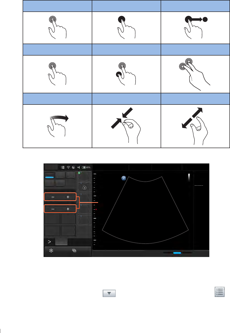
The system uses certain conventions throughout the interface to make it easy for you to learn and use:
Refer to the following table to control the system using gestures (See page )
Touch Touch and Hold Drag
Double-Tap Press and Tap Two-Finger Tap
x2
Flick Pinch Spread
To adjust the parameter value of a function, touch the plus/minus buttons (+/-)
2D Color PW
M CPA
Focus8.0
Dyn Range78
THI Full Screen
Dual Toggle
Freeze Acquire
Fn Key iScan TGC Home
2D
Menu
End Exam
Pen Res
Abdomen
12/5/2016 08:56 AM
C6-2
MI 0.72
TIS 0.03
76 Hz
16.0 cm
2D
Gen
Gn 43
DR 78
1/ 0/ 1
1/ 0/ 4
1
5
The plus/minus buttons (+/-)
Figure 1The plus/minus buttons (/-)
To type texts into a text field, touch the field and use the virtual keyboard Alternatively, you can add
pointing or input devices by connecting them to the USB ports on the system
To display a list, touch the down arrow To display the options, touch the menu icon
7
1 edii User Information Conventions
InnoSight Ultrasound System
P6992-4, EN, 16/12/6
To select/enable or deselect/disable a function, tap in the checkbox For example, check
Registered User uncheck Site Administrator
User Information Conventions
The User Manual uses certain conventions throughout the book to make it easier to find the information
you need
Control names and menu items or titles are spelled as they are on the system, and they appear in bold
text
The on-screen menu steps needed to perform a function are shown in a condensed form For example,
touch Menu > Settings > DICOM
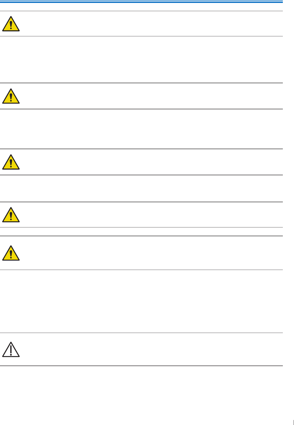
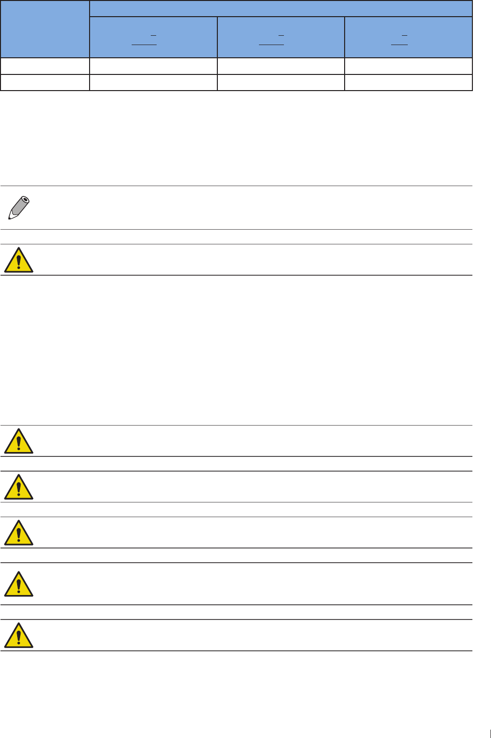
Refer to the following graphic symbols and numbering styles to alert you to important information:
This icon marks NOTES useful tips or additional information that help you get better use of
your product
This icon marks CAUTIONS notices describing actions or conditions that may damage your
product or cause injury, and consequently void your warranty or service contract or lose the
patient or system data
This icon marks WARNINGS instructions that must be followed Failure to observe can cause
damages to your product, or result in personal injuries, or even death
1
This numbering style is used for steps with callouts on graphics
1
This numbering style is used for steps with no callouts on graphics
1
This numbering style is used for callouts not associated with steps
System Warranty
The warranty is void if unauthorized personnel perform service or maintenance on the system To ensure
correct system performance and to obtain warranty service, please contact technical support For more
information, see Servicing your system on page 12 and Customer Service on page 3

InnoSight Ultrasound System
1
P6992-4, EN, 16/12/6
9
2 enin
2
P6992-4, EN, 16/12/6
2 Safety Information
Follow the procedures carefully and ensure that the power/electrical/environmental requirements
are satisfied Failure to observe the instructions or disregard the warnings may result in damages
to the system, personal injury, or even death of the operator or the patient
Observe the following precautions carefully
This system complies with Type BF general equipment and the EN661-1 standard, suitable for
continuous operation when connected as a system to a medical grade AC/DC power adapter or
operated from the tablet battery
Use only medical grade peripherals in the patient environment
Do not block or otherwise obstruct access to the AC plug at the wall Operators must be able to
quickly unplug the power cable at the wall in case of emergency
The system should only be used in a medical facility under the supervision of a trained physician
Only an authorized service technician should perform maintenance
Be extremely cautious when placing or moving the system
Always position the system on a stable surface where it cannot fall on the patient
Do not lift the system by the power cable or the transducer If either disconnects, the system
could fall on the patient
This system has been fully adjusted and tested prior to shipment from the factory Unauthorized
modifications will void your warranty
If this system or the transducer connected displays any signs of malfunction, turn off the system
immediately, disconnect it from the wall outlet, then contact technical support (See Customer
Service on page 3)
Do not use a power adapter other than the one supplied with the system Connecting the
system to an unknown power adapter is very dangerous and may lead to fire or explosion
Using cables, transducers, or accessories other than those specified for use with the system
may result in increased emissions or decreased immunity of the system
The power cable of the system should only be connected to a grounded power socket
Do not connect USB peripherals with an extended USB cable Extended connection may cause
unexpected usage fault
Only devices that comply with the EN661-1 standard, either electronically or mechanically, can be
connected to this system Recheck the leakage current and other safety performance indices of the
entire system to avoid potential system damage caused by leakage from a current superposition
Using accessories, transducers, peripherals, or cables not supplied with the system or
recommended by Philips can affect the system in the form of increased emissions or decreased
immunity to external EMI/EMC occurrences Non-specified peripherals, and cables in some cases,
can also increase leakage current or compromise the safety of the grounding scheme
This system does not incorporate any specialized protective measures in the event it is configured with
high-frequency operation devices The operator should use with caution in these types of applications
The system is in compliance with the Ingress Protection Marking ratings IP22
InnoSight Ultrasound System
Symbols 2 enin
1 P6992-4, EN, 16/12/6
Do not use this system under direct sunlight, near heat sources or in the presence of flammable
substances, otherwise an explosion may occur
When using this system for ultrasound examinations, use only the qualified ultrasound gel that complies
with system standards
Do not continuously scan the same part of a patient or expose the patient to prolonged
scanning, otherwise it may harm the patient
Do not stay at the same position for too long without taking a break while scanning patients to
prevent harm or neck injury
Follow the instructions on Chapter 4 Preparing the System in this User Manual for complete
instructions on the installation of the transducers, power supply units and all peripheral devices to the
system
Improper installation of peripherals to the system may cause damage to the system, peripherals ,
or personal injury to the operator or the patient
Do not use the system for any application until you have read, understood, and know all the safety
information, safety procedures, and emergency procedures contained in this chapter Operating
the system without a proper awareness of safe use could lead to fatal or other serious personal
injury
The system can contain environmentally hazardous materials such as, but not limited to: heavy metals,
general recyclable metals, and plastics This product should be recycled according to local and national
guidelines for recycling electronic equipment
When using additional peripheral equipment powered from an electrical source other than the
ultrasound system, the combination is considered to be a medical system It is your responsibility to
comply with IEC 661-1 and test the system to those requirements
Do not use non-medical peripherals, such as report printers, within 1 m ( ft) of a patient, unless
the non-medical peripherals receive power from an isolation transformer that meets medical safety
standards, as defined by standard IEC 661-1
Images printed on a report printer are intended only for reference and should not be used for diagnostic
purposes
For proper disposal of this system, contact your local Philips representative
Symbols
The following symbols provide information about the system’s labels and regulatory compliance
Do not use a brush on the system’s labels
System Label Icons
Symbols Descriptions
Product Model
Serial Number
11
2 enin Symbols
InnoSight Ultrasound System
P6992-4, EN, 16/12/6
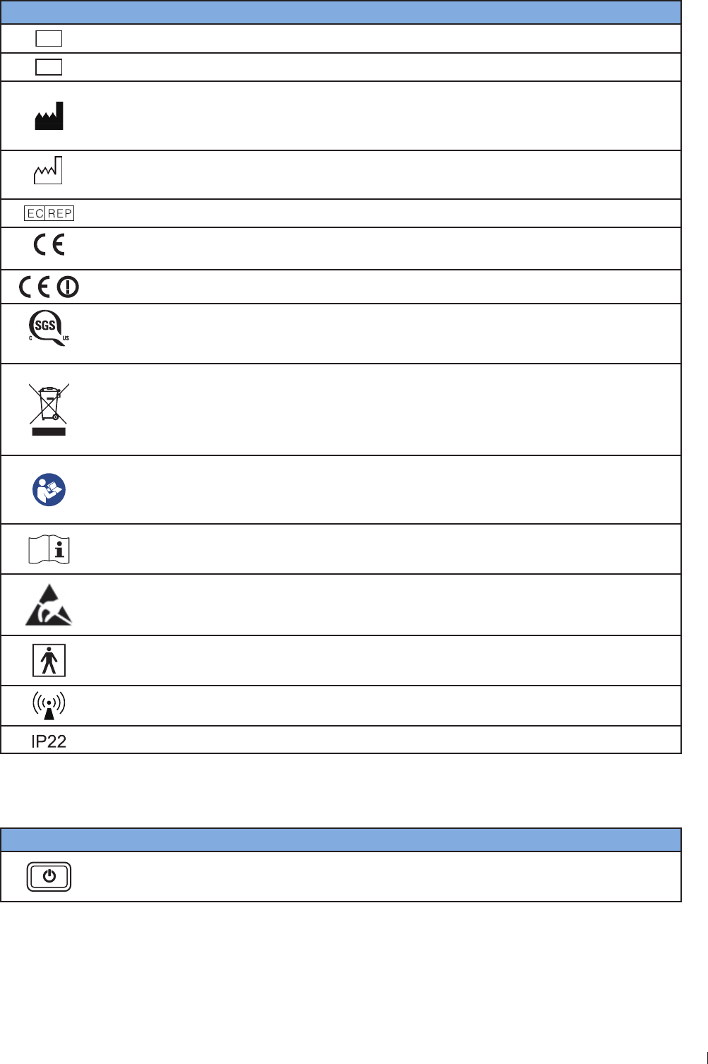
Symbols Descriptions
SVC
Philips Service Code
UDI
Unique Device Identification
Manufacturer Mark
Manufacturer
Qisda Corporation manufactures the system
201X-XX-XX
Manufacture Date
EU/EC European Authorized Representative
0120
CE Marking Certification with Notified Body Number 0120
Compliance to R&TTE Directive
710435
Notify Body Certificate
Final Disposal of Your System
Final disposal is when you dispose of the system in such a way that it can no longer be
used for its intended purposes
For more information, see Recycling, Reuse, and Disposal on page 3
Refer to the User Manual
Indicates that the user should read the User Manual for information on using this
equipment
Operating instructions
Indicates that the user should see the instructions for use for safety information
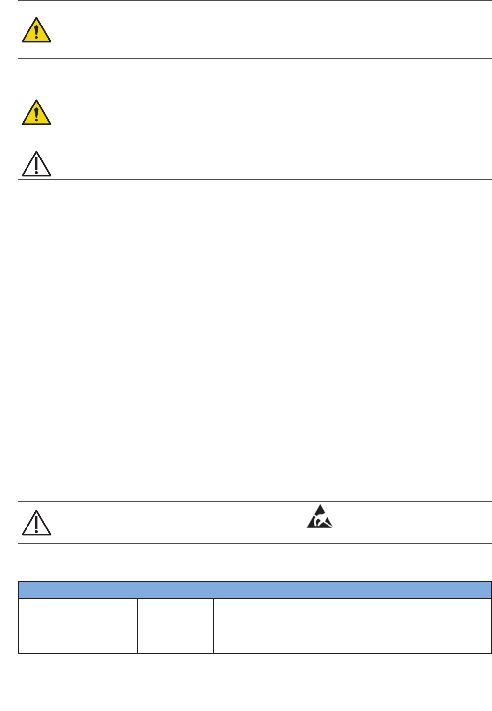
Identifies ESD (electrostatic-discharge) sensitivity of a connector that is not tested as
specified in IEC 661-1-2 Do not touch exposed connector pins Touching exposed pins
can cause electrostatic discharge, which can damage the product
Type BF Equipment Applied Part
The Ultrasound System provides protection against electric shock
Include RF transmitters, apply RF electromagnetic energy for diagnosis
Tablet IP Code, International Protection Marking
System Button
Symbols Descriptions
Power button
Press and hold the Power button to turn on/off the system
InnoSight Ultrasound System
Electrical Safety 2 enin
12 P6992-4, EN, 16/12/6
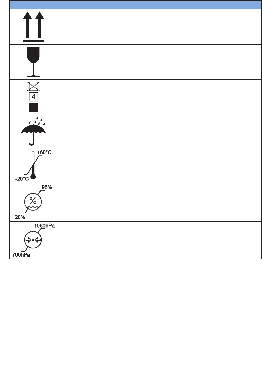
Shipping Label Icons
Symbols Descriptions
This Side Up
Fragile
Maximum Stacking Height
Sun and Rain
Temperature
The system must be stored in the original shipping container in environments
between -2C and 6C (-13F and 14F) The temperature while operating the
system should be kept between 1C and 4C (32F and 14F)
Humidity
The system must be stored in the original shipping container in environments with
2 to 9 relative humidity and non-condensing The humidity while operating the
system should be kept between 2 to relative humidity and non-condensing
Air Pressure
The system must be stored in the original shipping container in environments
between hPa (2 mmHg) and 16 hPa (9 mmHg) air pressure
Electrical Safety
Only trained medical personnel should operate this system This system complies with the following
standards:
13
2 enin Electrical Safety
InnoSight Ultrasound System
P6992-4, EN, 16/12/6
Electrical:
»IEC 661-1:2AMD1:212, EN 661-1:26A12:214, Medical electrical equipment - Part 1:
General requirements for basic safety and essential performance
»IEC 661-1-2:2 Medical electrical equipment - Part 1-2: General requirements for basic safety
and essential performance - Collateral standard: Electromagnetic compatibility - Requirements and
tests CISPR 11: 21 AMD1:216 Industrial, scientific and medical equipment - Radio-frequency
disturbance characteristics - Limits and methods of measurement
»IEC 661-2-3:2AMD1:21, Medical electrical equipment - Part 2-3: Particular requirements
for the basic safety and essential performance of ultrasonic medical diagnostic and monitoring
equipment
EMC/EMI:
»IEC 661-1-2:2/AC:21, CISPR 11 Group I Class B
Harmful liquid protection:
»For the main system: IP22
»For the transducer: IPx
»For the power adapter: IP21
»For maximum safety, observe the following guidelines strictly:
The system and patient-applied parts meet the standard IEC 661-1 Applied voltages exceeding
the standard, although unlikely, may result in electrical shock to the patient or operator
Shock hazards exist if the power adapter is damaged or is not properly grounded Use only the supplied
medical grade power adapter
Do not remove or try to circumvent the grounding wire If the protective grounding of the system
is questionable, disconnect the system from the power source and run it on its internal battery
Plug the system into a hospital-grade, three-hole outlet, and do not circumvent the power cord
To avoid the risk of electric shock, connect the system only to properly grounded wall (wall/mains)
outlets
Only authorized service technicians can make internal replacements of the system
Do not operate the system in the presence of flammable gases or anesthetics Explosion can
result The system is not compliant in AP/APG environments as defined by IEC 661-1
Do not use a transducer if the transducer or cable is damaged Contact technical support for
replacement of the damaged equipment (See Customer Service on page 3)
All peripheral devices connected to the system must comply with IEC 661 or IEC 69-1
To avoid risk of electrical shock hazards, always inspect the transducer before use Check the face,
housing, and cable before use Do not use if the face is cracked, chipped, or torn the housing is
damaged or the cable is abraded
Transducer cables have strain reliefs at terminations Inspect cables regularly to detect
damaged, frayed, or broken cables that might contact a patient
C9-4v are invasive transducers The operator should immediately stop using the C9-4v
transducer when its surface temperature reaches 43C
InnoSight Ultrasound System
Electrical Safety 2 enin
14 P6992-4, EN, 16/12/6
Battery Usage/Disposal
Do not disassemble the system
Use only the supplied battery Using an unapproved battery may cause the system to explode
and result in serious damage to your health or property
Do not replace, heat, crush, puncture, short external contacts, or incinerate the battery
Use only the supplied power adapter to charge the battery
Incorrect use of the battery may cause a leak of chemicals or explosion The leak of chemicals may
harm the skin If any chemicals leak from the device, use a dry cloth to wipe it clean and contact
your local Philips representative for help
Dispose of used batteries according to the instructions
Electrical Fast Transients (EFT)
The system complies with the IEC 661-1-2 3rd edition standard for susceptibility to electrical fast
transients (EFT) on the power line However, if the system experiences EFT on the power line, artifacts
(vertical lines, excessive noise in image, etc) may appear on the ultrasound image To eliminate these
artifacts caused by an EFT condition, the operator should either:
Disconnect the system from the power source by unplugging the power cord from the tablet, and run
the system on its internal battery
Or
Unplug the power cord from the wall and move to a different power source that is not experiencing this
condition
Electromagnetic Interference (EMI)
Medical electrical equipment such as the system requires special precautions regarding electromagnetic
compatibility, and must be installed and put into service according to the following electromagnetic tables
All Equipment
The system is intended for use in the electromagnetic environment specified below The customer
or operator of the InnoSight Diagnostic Ultrasound System should ensure that it is used in such an
environment
On connectors labeled with the ESD sensitivity symbol , do not touch the connector pins,
and always observe the preceding ESD precautions when handling or connecting transducers
Guidance and Manufacturer’s Declaration - Electromagnetic Emissions - All Equipment
Emissions test Compliance Electromagnetic environment - Guidance
RF Emissions CISPR 11 Group 1 The InnoSight Diagnostic Ultrasound System uses RF energy
only for its internal function Therefore, its RF emissions
are very low and are not likely to cause any interference in
nearby electronic equipment

1
2 enin Electrical Safety
InnoSight Ultrasound System
P6992-4, EN, 16/12/6
Emissions test Compliance Electromagnetic environment - Guidance
RF Emissions CISPR 11 Class B The InnoSight Diagnostic Ultrasound System is suitable for
use in all establishments, including domestic, and those
directly connected to the public low-voltage power supply
network that supplies buildings used for domestic purposes
Harmonics IEC 61-3-2 Class A or B
Flicker IEC 61-3-3 Complies
RF Emissions CISPR 14-1 Complies The InnoSight Diagnostic Ultrasound System is not suitable
for interconnection with other equipment
RF Emissions CISPR 1 Complies The InnoSight Diagnostic Ultrasound System is not suitable
for interconnection with other equipment
Guidance and Manufacturer’s Declaration - Electromagnetic Immunity - All Equipment
Immunity test IEC 60601 test
level
Compliance
level Electromagnetic environment - Guidance
ESD
IEC 61-4-2
6 kV Contact
kV Air
As specified Floors should be wood, concrete or ceramic
tile If floors are synthetic, the relative humidity
should be at least 3
EFT
IEC 61-4-4
2 kV Mains
1kV I/Os
As specified Mains power quality should be that of a typical
commercial or hospital environment
Surge IEC 61-4- 1 kV Differential
2 kV Common
As specified
Voltage dips/
Dropout IEC 61-
4-11
9 dip for
cycle
6 dip for
cycles
3 dip for 2
cycles
9 dip for
seconds
As specified Mains power quality should be that of a typical
commercial or hospital environment If the user
of the InnoSight Diagnostic Ultrasound System
requires continued operation during power
mains interruptions, it is recommended that
the InnoSight Diagnostic Ultrasound System be
powered from an uninterruptible power supply
or battery
Power frequency
/6 Hz
Magnetic field
IEC 61-4-
3 A/m As specified Power frequency magnetic fields should
be that of a typical commercial or hospital
environment
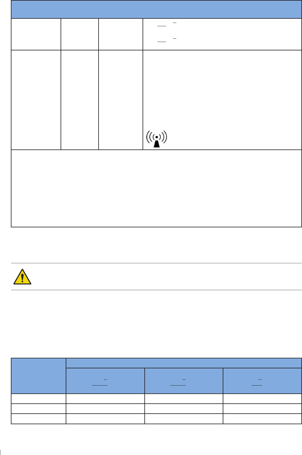
Guidance and Manufacturer’s Declaration - Electromagnetic Immunity - Non-life-supporting Equipment
Immunity test IEC 60601
test level
Compliance
level Electromagnetic environment - Guidance
Portable and mobile RF communications equipment
should be used no closer to any part of the InnoSight
Diagnostic Ultrasound System, including cables, than the
recommended separation distance calculated from the
equation applicable to the frequency of the transmitter
Recommended separation distance
Conducted RF
IEC 61-4-6
3 Vrms
1 Hz to
MHz
V1 3 Vrms d P
3
V1
InnoSight Ultrasound System
Electrical Safety 2 enin
16 P6992-4, EN, 16/12/6
Immunity test IEC 60601
test level
Compliance
level Electromagnetic environment - Guidance
Radiated RF
IEC 61-4-3
3 V/m
MHz to
2 GHz
E1 3 V/m d P
3
E1
MHz to MHz
d P
7
E1
MHz to 2 GHz
Where P is the maximum output power rating of the
transmitter in watts (W) according to the transmitter
manufacturer, and d is the recommended separation
distance in meters (m)
Field strengths from fixed RF transmitters, as determined
by an electromagnetic site surveya, should be less than
the compliance level in each frequency rangeb
Interference may occur in the vicinity of equipment
marked with the following symbol:
aField strengths from fixed transmitters, such as base stations for radio (cellular/cordless) telephones and
land mobile radios, amateur radio, AM and FM radio broadcast and TV broadcast cannot be predicted
theoretically with accuracy
To assess the electromagnetic environment due to fixed RF transmitters, an electromagnetic site survey
should be considered If the measured field strength in the location in which the InnoSight Diagnostic
Ultrasound System is used exceeds the applicable RF compliance level above, the system should be
observed to verify normal operation If abnormal performance is observed, additional measures may be
necessary, such as reorienting or relocating the system
bOver the frequency range 1 kHz to MHz, field strengths should be less than 3 V/m
To limit exposure to electromagnetic interference from nearby equipment that can degrade image quality,
you should operate the system under EMI conditions that minimize power supply transients, mechanical
interactions, vibration, and thermal, optical, and ionizing radiation
Using cables, transducers, and accessories other than those specified for use with the system
may result in increased emissions from, or decreased immunity of, the system
ME equipment has been tested for radiated RF immunity only at selected frequencies
Separation Distances
The InnoSight Diagnostic Ultrasound System is intended for use in the electromagnetic environment in
which radiated disturbances are controlled The customer or operator of the system can help prevent
electromagnetic interference by maintaining a minimum distance between portable and mobile RF
Communications Equipment and the system as recommended below, according to the maximum output
power of the communications equipment
Maximum
Output Power
of Transmitter
Watts (W)
Separation Distance According to Frequency of Transmitter Meters (m)
1 kHz to MHz
D
3P
V1
MHz to MHz
D
3P
E1
MHz to 2 GHz
D
P
E1
1 12 m 12 m 24 m
1 3 m 3 m 4 m
1 11 m 11 m 234 m
1
2 enin Mechanical Safety
InnoSight Ultrasound System
P6992-4, EN, 16/12/6
Maximum
Output Power
of Transmitter
Watts (W)
Separation Distance According to Frequency of Transmitter Meters (m)
1 kHz to MHz
D
3P
V1
MHz to MHz
D
3P
E1
MHz to 2 GHz
D
P
E1
1 369 m 369 m 3 m
1 116 m 116 m 2334 m
Tale 1Separation distances
For transmitters rated at a maximum output power not listed above, the recommended separation distance
d in meters (m) can be estimated using the equation applicable to the frequency of the transmitter,
where P is the maximum output power rate of the transmitter in watts (W) according to the transmitter
manufacturer
At MHz and MHz, the separation distance for the higher frequency range applies
These guidelines may not apply in all situations Electromagnetic propagation is affected by
absorption and reflection from structures, objects and people
Operation of the equipment below that value may cause inaccurate results
Surges to AC Power Mains
If the system is powered from AC mains that could experience surges above 1 kV (for example, from
extreme lightning conditions), additional surge suppression is recommended
Mechanical Safety
Observe the following precautions when using the system for mechanical safety
When attempting to overcome an obstacle, do not push the system from either side with
excessive force, which could cause the system to tip over
Position external peripheral devices away from the system Ensure that they are secure Do not
stack them on the system
When positioning the system, move it carefully to avoid pinching hands or extremities against
other objects, such as a bed rail
Be aware of the caster wheels on the system cart, especially when moving the system The system
cart could cause injury to you or others if it rolls over feet or into shins Use with caution when
going up or down the ramps
The brakes are intended as a convenience To increase cart security, use wheel chocks when the
system cart is parked

InnoSight Ultrasound System
Equipment Protection 2 enin
1 P6992-4, EN, 16/12/6
To avoid injury, we recommend against lifting the system cart
Never park the system cart on an incline If you park the system on a floor that is tilted 1 degrees
or more and set the brakes, one of the braked casters might not be touching the floor, which can
cause the system to move
When performing a needle biopsy, if the system is not mounted correctly on the system cart, or if
the system cart is not parked safely, unintended movement of the system resulting in movement
of the needle during use may cause injury to you or others
Do not roll the system over transducer cables or power cords
Equipment Protection
Observe the following precautions to protect your system
Excessive bending or twisting of cables on patient-applied parts may cause failure or intermittent
operation of the system Do not roll the system over cables, which may damage them
Do not submerge the cables of patient-applied parts in solution The cables are not liquid-tight
beyond the applied part/cable or cable/connector interfaces
Do not submerge the transducer beyond its binding line
Do not submerge the transducer connector in any liquid
For optimal performance, connect your system to a circuit dedicated solely for the system Do not
connect life-support devices to the same circuit as the system
Improper cleaning or sterilization of a patient-applied part may cause permanent damage For
cleaning and disinfection instructions, see Chapter 1 Transducer Care and Chapter 11 System
Maintenance
RF Safety
The system should be operated in a location that is no closer than listed in Non-Life-Supporting
Equipment to any part of RF communications equipment that may disturb its functions If abnormal
performance is observed, additional measures may be necessary, such as re-orienting or relocating the
equipment The system should be separated by at least the distances specified in the table referenced
above
The system is intended for use in an electromagnetic environment where radiated RF disturbances are
controlled The customer or the user of the system can help prevent electromagnetic interference by
maintaining a minimum distance between portable and mobile RF communications equipment (transmitters)
and the system according to the maximum output power of the communications equipment

19
2 enin Biological Safety
InnoSight Ultrasound System
P6992-4, EN, 16/12/6
Biological Safety
This product, as with all ultrasound equipment, should be used only for valid reasons and should be
used both for the shortest period of time and at the lowest power settings necessary (ALARA - As Low
As Reasonably Achievable) to produce diagnostically acceptable images The AIUM offers the following
guidelines:
Clinical Safety Quoted from AIUM
Approved March 26, 1997
Diagnostic ultrasound has been in use since the late 1950s. Given its known benefits and recognized
efficacy for medical diagnosis, including use during human pregnancy, the American Institute of
Ultrasound in Medicine herein addresses the clinical safety of such use.
There are no confirmed biological effects on patients or instrument operators caused by exposures
from present diagnostic ultrasound instruments. Although the possibility exists that such biological
effects may be identified in the future, current data indicate that the benefits to patients of the
prudent use of diagnostic ultrasound outweigh the risks, if any that may be present.
Heating
Elevating tissue temperature during obstetrical examinations creates medical concerns At the embryo
development stage, the rise in temperature and the length of time exposed to heat combine to determine
potential detrimental effects Exercise caution, particularly during Color imaging exams The Thermal
Index (TI) provides a statistical estimate of the potential temperature elevation (in centigrade) of tissue
temperature Two forms of TI are available: TIS, for soft tissue exposures and TIB, for instances when bone
lies near the beam focus
Cavitation
Cavitation may occur when sound passes through an area that contains a cavity, such as a gas bubble or air
pocket (in the lung or intestine, for example) During the process of cavitation, the sound wave may cause
the bubble to contract or resonate This oscillation may cause the bubbles to explode and damage the
tissue The Mechanical Index (MI) has been created to help operators accurately evaluate the likelihood of
cavitation and the related adverse effects
Safe Scanning Guideline
Ultrasound should only be used for medical diagnosis and only by trained medical personnel
Diagnostic ultrasound procedures should be done only by personnel fully trained in the use of
the system, in the interpretation of the results and images, and in the safe use of ultrasound
(including education as to potential hazards)
Operators should understand the likely influence of the machine controls, the operating
mode (eg 2D mode, Color or Spectral Doppler) and the transducer frequency on thermal and
cavitation hazards
Use a low output power default setting for each new patient Output should only be increased during
the examination if penetration is still required to achieve a satisfactory result, and after the Gain control
has been adjusted to its maximum value
Maintain the shortest examination time necessary to produce a useful diagnostic result
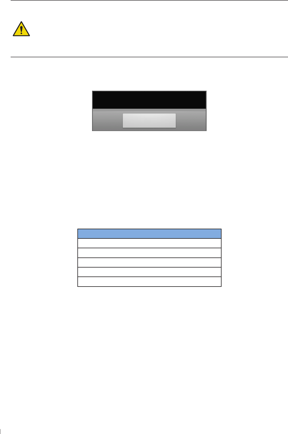
InnoSight Ultrasound System
Biological Safety 2 enin
20 P6992-4, EN, 16/12/6
Take particular care to reduce output and minimize exposure time of an embryo or fetus when
the temperature of the mother is already elevated
Take particular care to reduce the risk of thermal hazard during diagnostic ultrasound when
exposing an embryo less than eight weeks after gestation, or the head, brain or spine of any
fetus or neonate
Although applicable to any transducer, take particular care during trans-vaginal exams during
the first eight weeks of gestation
During continuous operation, the system temperature may become too high If the following system
message displays during a real-time scan, touch OK and the system displays frozen imaging screen To
resume scanning, wait until the system engine cools down
System temperature is high. Please cease
the current scan for a few minutes.
OK
Operators should continually monitor the on-screen thermal index (TI) and mechanical index (MI) values
and use control settings that keep these settings as low as possible while still achieving diagnostically
useful results In obstetric examinations, TIS (soft tissue thermal index) should be monitored during
scans carried out in the first eight weeks after gestation, and TIB (bone thermal index) thereafter
MI 3 Minor damage is likely to happen to neonatal lung or intestine If such exposure is
necessary, reduce the exposure time as much as possible
MI Risk of cavitation exists if an ultrasound contrast agent containing gas microspheres is
being used There is a theoretical risk of cavitation without the presence of ultrasound
contrast agents The risk increases with MI values above this threshold
TI The overall exposure time of an embryo or fetus should be restricted in accordance with
the following table as a reference
TI Maximum exposure time (minutes)
60
1 3
1 1
2 4
2 1
Tale 2Maximum exposure time recommended for an embryo or fetus
Diagnostic ultrasound has the potential for both false positive and false negative results Misdiagnosis
is far more dangerous than any effect that might result from the ultrasound exposure Therefore,
diagnostic ultrasound should be performed only by those with sufficient training and education
Non-diagnostic use of ultrasound equipment is not generally recommended Examples of non-diagnostic
uses of ultrasound equipment include repeated scans for operator training, equipment demonstration
using normal subjects, and the production of souvenir pictures or videos of a fetus For equipment of
which the safety indices are displayed over their full range of values, the TI should always be less than
and the MI should always be less than 3 Avoid frequent repeated exposure of any subject Scans
in the first trimester of pregnancy should not be carried out for the sole purpose of producing souvenir
videos or photographs, nor should their production involve increasing the exposure levels or extending
the scan times beyond those needed for clinical purposes

21
2 enin Operator Safety
InnoSight Ultrasound System
P6992-4, EN, 16/12/6
FDA Medical Alert on Latex
March 29, 1991, Allergic reactions to latex-containing medical devices
Because of reports of severe allergic reactions to medical devices containing latex (natural rubber), the
FDA is advising health care professionals to identify their latex sensitive patients and be prepared to treat
allergic reactions promptly Patient reactions to latex have ranged from contact urticaria to systemic Latex
is a component of many medical devices, including surgical and examination gloves, catheters, intubation
tubes, anesthesia masks, and dental dams
Reports to the FDA of allergic reactions to latex-containing medical devices have increased lately One brand
of latex cuffed enema tips was recently recalled after several patients died as a result of anaphylactoid
reactions during barium enema procedures More reports of latex sensitivity have also been found in the
medical literature Repeated exposure to latex both in medical devices and in other consumer products
may be part of the reason that the prevalence of latex sensitivity appears to be increasing For example,
it has been reported that 6 to of surgical personnel and 1 to 4 of spina bifida patients are latex
sensitive
Proteins in the latex itself appear to be the primary source of the allergic reactions Although it is not now
known how much protein is likely to cause severe reactions, the FDA is working with manufacturers of
latex-containing medical devices to make protein levels in their products as low as possible
FDA’s recommendations to health professionals in regard to this problem are as follows:
When taking general histories of patients, include questions about latex sensitivity For surgical and
radiology patients, spina bifida patients and health care workers, this recommendation is especially
important Questions about itching, rash or wheezing after wearing latex gloves or inflating a toy
balloon may be useful Patients with positive histories should have their charts flagged
If latex sensitivity is suspected, consider using devices made with alternative materials, such as plastic
For example, a health professional could wear a non-latex glove over the latex glove if the patient is
sensitive If both the health professional and the patient are sensitive, a latex middle glove could be
used (Latex gloves labeled Hypoallergenic may not always prevent adverse reactions)
Whenever latex-containing medical devices are used, especially when the latex comes in contact with
mucous membranes, be alert to the possibility of an allergic reaction
If an allergic reaction does occur and latex is suspected, advise the patient of a possible latex sensitivity
and consider an immunologic evaluation
Advise the patient to tell health professionals and emergency personnel about any known latex
sensitivity before undergoing medical procedures Consider advising patients with severe latex
sensitivity to wear a medical identification bracelet
The FDA is asking health professionals to report incidents of adverse reactions to latex or other materials
used in medical devices (See the October 199 FDA Drug Bulletin) To report an incident, contact the FDA
Problem Reporting Program, MedWatch, at 1--332-1, or on the Internet:
wwwfdagov/Safety/MedWatch/
For a single copy of a reference list on latex sensitivity, write to: LATE, FDA, HFZ-22, Rockville, MD 2
Operator Safety
The following issues and situations can affect operator safety when you are using an ultrasound system

InnoSight Ultrasound System
Operator Safety 2 enin
22 P6992-4, EN, 16/12/6
Repetitive Strain Injury
Repetitive ultrasound scanning has been associated with carpal tunnel syndrome (CTS) and related
musculoskeletal problems Some investigators have looked at a large population of sonographers with
different types of equipment An article, with feedback from a smaller geographical area, makes the
following recommendations:
Maintain your joints in optimum positions with a balanced posture while scanning
Allow frequent breaks to give soft tissue a chance to recuperate from awkward positions and repetitive
movement
Avoid gripping the transducer with excessive force
Repetitive Strain References
Pike, I, et al Prevalence of Musculoskeletal Disorders and Related Work and Personal Factors Among
Diagnostic Medical Sonographers ournal of Diagnostic Medical Sonographers, Vol 13,No : 219-22,
September 199
Necas, M Musculoskeletal Symptomatology and Repetitive Strain Injuries in Diagnostic Medical
Sonographer Journal of Diagnostic Medical Sonographers, 266-22, November/December 1996
Philips Transducers
Use only transducers that are approved by Philips for use with your Philips ultrasound system See Clinical
Applications and Transducers on page 31 for a list of the transducers that are compatible with your
system In the United States, the FDA 1(k) regulatory clearance for use of the product is applicable only
when Philips-manufactured transducers are connected to the system
Glutaraldehyde Exposure
The United States Occupational Safety and Health Administration (OSHA) has issued a regulation
covering levels of acceptable glutaraldehyde exposure in the working environment Philips does not sell
glutaraldehyde-based disinfectants with its products, but this type of disinfectant is recommended for the
disinfection of transducers used in TEE, intraoperative, endocavity, and biopsy procedures To reduce the
presence of glutaraldehyde fumes in the air, be sure to use a covered or ventilated soaking basin Such
systems are commercially available The most-current information about disinfection products and Philips
transducers can be found on the Philips Transducer Care website:
wwwPhilipscom/transducercare
Infection Control
Issues related to infection control affect the operator and the patient Follow the infection-control
procedures established in your facility for the protection of both the staff and the patient
Removing Blood and Infectious Material from the System
It is important to clean and maintain the ultrasound system and peripherals If the equipment has come in
contact with blood or infectious material, clean and disinfect the system and peripherals according to the
instructions in Chapter 11 System Maintenance
Disposable Drape
If you believe contamination of the system might occur during an exam, Philips recommends that you take
universal precautions and cover the system with a disposable drape Consult your facility’s rules regarding
equipment use in the presence of infectious disease
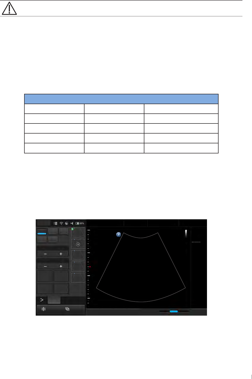
23
2 enin Waterproof and Dustproof Ratings
InnoSight Ultrasound System
P6992-4, EN, 16/12/6
Position the disposable drape so that it does not block the vents on the system, the monitors, or
the peripherals
Waterproof and Dustproof Ratings
The system has a degree of protection from ingress of water and particulate matter, but the tablet is not
approved for use where it would be exposed to liquids If it is used in environments where it might be
exposed to liquids, the tablet must be covered by a drape, such as a Civco 66-16 These environments
include, but are not limited to, outpatient and private office procedures such as biopsies, office visits, and
other traditional, non-invasive scanning
The following table lists the applied parts and their levels of protection
Component Use IP level
Ultrasound System Ultrasound system IP22
C6-2 transducer Ultrasound transducer IP (at transducer head)
L12-4 transducer Ultrasound transducer IP (at transducer head)
S4-2 transducer Ultrasound transducer IP (at transducer head)
C9-4v transducer Ultrasound transducer IP (at transducer head)
Tale 3Waterproof and dustproof ratings
Understanding the MI/TI Display
The system allows full software control of acoustic output When powering on the system or creating a new
exam, scan parameters should be set to default preset All of the default presets are compliant with FDA
requirements TI/MI information are displayed in real-time in the scan properties area
2D Color PW
M CPA
Focus8.0
Dyn Range78
THI Full Screen
Dual Toggle
Fn Key iScan TGC Home
2D
Menu
End Exam
Pen Res
Abdomen
12/5/2016 08:56 AM
C6-2
MI 0.72
TIS 0.03
16.0 cm
2D
Gen
Gn 43
DR 78
1/ 0/ 1
1/ 0/ 4
1
5
Figure 2MI/TI on-screen display format
In the following table, the MI or TI index is equal or greater than 1 for transducer/mode combinations
marked V

InnoSight Ultrasound System
Understanding the MI/TI Display 2 enin
24 P6992-4, EN, 16/12/6
Mode / Transducer C6-2 Curved Linear
Array 2-6 MHz
L12-4 Linear Array
4-12 MHz
S4-2 Phased Array
64 elements
2-4 MHz
C9-4v Micro
Curved Linear
Array 4-9 MHz
2D
2DM-Mode
THI, 2D
THI, 2DM-Mode
PW Doppler
2DColor V
THIColor, 2D V
Tale 4MI/TI generating from applicable transducer/mode combinations
Track-3 follows the Output Display Standard for systems which include fetal Doppler applications The
acoustic output will not be evaluated on an application-specific basis, but the global maximum de-rated
Ispta must be 2 mW/cm2 and either the global maximum MI must be 19, or the global maximum de-
rated Isppa must be 19 W/cm2 An exception is for ophthalmic use, in which case the TImax (TIS) is not
to exceed 1 Ispta3 mW/CM2, and MI 23 Track-3 gives the operator the freedom to increase the
output acoustic power for a specific exam, and still limit output acoustic power within the global maximum
de-rated Ispta 2 mW/cm2 under an Output Display Standard
The system design allows full software control of the acoustic output, entry of new patient identification
data or change from a non-foetal to a foetal application, and the system may switch to an appropriate
default setting upon powering on These default setting levels are established before shipping and may be
reconfigured by the operator
For any ultrasound systems, Track-3 provides an Output Indices Display Standard The ultrasound system
and its User Manual contain the information regarding an ALARA (As Low As Reasonably Achievable)
education program from the clinical end-user and the acoustic output indices, MI and TI The MI describes
the likelihood of cavitation, and the TI offers the predicted maximum temperature rise in tissue as a result
of the diagnostic examination In general, a temperature increase of 2C must be present consistently
at one spot for 2 hours to cause possible fetal abnormalities Avoiding a local temperature rise above 1C
should ensure that no thermally induced biologic effect occurs When referring to the TI for potential
thermal effect, a TI equal to 1 does not mean the temperature will rise 1C It only means an increased
potential for thermal effects can be expected as the TI increases A high index does not mean that bioeffects
are occurring, but only that the potential exists and there is no consideration in the TI for the scan duration,
so minimizing the overall scan time will reduce the potential for effects These operator control and display
features move the safety responsibility from the manufacturer to the operator So it is very important to
have the ultrasound systems display the acoustic output indices correctly and the well-educated operator
to interpret the value appropriately
RF: De-rating factor
In Situ intensity and pressure cannot currently be measured Therefore, the acoustic power measurement is
normally done in the water tank, and when soft tissue replaces water along the ultrasound path, a decrease
in intensity is expected The fractional reduction in intensity caused by attenuation is denoted by the de-
rating factor (RF),
RF 1 (-1 afz)
Where a is the attenuation coefficient in dB cm-1 MHz-1, f is the transducer center frequency, and z is the
distance along the beam axis between the source and the point of interest

2
2 enin Understanding the MI/TI Display
InnoSight Ultrasound System
P6992-4, EN, 16/12/6
De-rating factor RF for the various distances and frequencies with attenuation coefficient 3 dB cm-1 MHz-
1 in homogeneous soft tissue is listed in the following table An example is if the operator uses MHz
frequency, the power will be attenuated by at cm, or 3 x x -112 dB The De-rated
Intensity is also referred to as 3’ at the end (eg Ispta3)
Distance (cm) Frequency (MHz)
1 3 5 7.5
1 9332 12 9
21 66 12 34
3 12 3 34 2113
46 436 212 129
34 1
666 24 129 44
76166 2344 91 266
4 193 631 1
Tale 5
I’ I RFWhere I’ is the intensity in soft tissue, I is the time-averaged intensity measured in water
TI
TI is defined as the ratio of the In Situ acoustic power (W3) to the acoustic power required to raise tissue
temperature by 1C (Wdeg),
TI W3 / Wdeg
Three TIs corresponding to soft tissue (TIS) for abdominal bone (TIB) for fetal and neonatal cephalic and
cranial bone (TIC) for pediatric and adult cephalic, have been developed for applications in different exams
An estimate of the acoustic power in milliwatts necessary to produce a 1C temperature elevation in soft
tissue is:
Wdeg 21 / fc
For model 1 to 4, where fc is the center frequency in MHz
Wdeg 4 D
For model and 6, where (beam shape factor) is 1, D is the aperture diameter in cm at the depth of
interest
MI
Cavitation is more likely to occur at high pressures and low frequencies in pulse ultrasound wave in the
tissue, which contains a bubble or air pocket (for instance, the lung, intestine, or scan with gas contrast
agents) The threshold under optimum conditions of pulsed ultrasound is predicted by the ratio of the peak
pressure to the square root of the frequency
MI Pr’ / sqrt(fc)
Pr’ is the de-rated (3) peak rare-fractional pressure in Mpa at the point where PII is the maximum, and
fc is the center frequency in MHz PII is the Pulse Intensity Integral that the total energy per unit area
carried by the wave during the time duration of the pulse The peak rare-fractional pressure is measured in
hydrophone maximum negative voltage normalized by the hydrophone calibration parameter

InnoSight Ultrasound System
Transducer Surface Temperature Rise 2 enin
26 P6992-4, EN, 16/12/6
Display Guideline
Thermal Index (TI) consists of two indices: soft tissue (TIS) and bone (TIB) TIB is only displayed in non-
scanning modes, such as M-mode, PW mode and CW mode TIS is displayed in all scan modes The
index is continuously displayed over a range of 1 to 6 in increments of 1 Mechanical Index (MI) is
continuously displayed over a range of 1 to 19 in increments of 1
Display and Report in Different Modes
For 2D Mode
Display and report only MI and TIS
For Color Mode
Display and report only MI and TIS
For Doppler Mode
Display and report MI, TIS and TIB
Below is a simple guideline for the operator when TI exceeds one limit exposure time to 4(6-TI) minutes based
on the ‘National Council on Radiation Protection. Exposure Criteria for Medical Diagnostic Ultrasound: I.
Criteria Based on Thermal Mechanisms. Report No.113 1992’
Operator Control Features
The operator should be aware that certain operator controls may affect the acoustic output It is
recommended to use the default (or lowest) output power setting and compensate using Gain control to
acquire an image Other than the output power setting in the Soft Menu, which has the most direct impact
on the power the PRF (Pulse Repetition Frequency), image sector size, frame rate, depth, and focal position
also slightly affect the output power The default setting is normally around , occasionally 9, of the
allowable power, depending on the exam type
Transducer Surface Temperature Rise
The table below lists the measured surface temperature rise from ambient (23C 3C) of transducers used
on the system The temperatures were measured in accordance with EN 661-2-3 cl2111 and cl2113
with controls and settings positioned to give maximum temperatures
Test External use (°C) Non-external Use (°C)
C6-2 S4-2 L12-4 C9-4v
Simulated use 1 14 3 19
Still air 3 36 6 33
Tale 6Transducer surface temperature rise
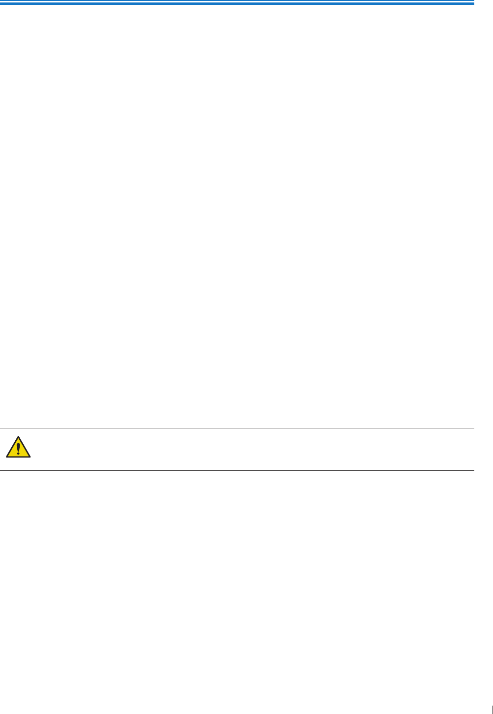
27
eie System Capabilities
3
P6992-4, EN, 16/12/6
3 Overview
Acquaint yourself with the system and its components in this chapter
System Capabilities
The InnoSight Diagnostic Ultrasound System is intended for Obstetric imaging, and OB/GYN, Gynecology
imaging, Cardiac imaging, Vascular imaging, and general imaging purpose, and related analysis The system
cart is ergonomically designed to be both highly mobile and adjustable for a range of users and operating
conditions The system can be used for 2D grayscale, M-Mode, Color, Doppler, PW, and CW imaging
depending on the transducer The system also supports duplex, and triplex imaging The system provides
measurement tools, analysis options, and DICOM network capabilities Refer to the following standard
features
Imaging
The following scan modes and features are available, if supported by the transducer for the application:
2D
M-mode
Anatomical M-mode
Color Doppler
Color Power Angio (CPA)
Directional CPA
Tissue Harmonic Imaging (THI)
Pulse Inversion THI
RES image processing
SonoCT Real-time Compound Imaging
High Q Automatic Doppler
The system does not support the biopsy guide function Do not use nor assemble any kind of
needle guide kits/brackets on the transducer supported to avoid transducer damage or hurting
the patient
Transducer Types
The available transducer types are a curved linear array transducer, a linear array transducer, a phased
array transducer, and a micro-curved linear array transducer Applications for specific transducers are listed
in Indications for Use and Supporting Transducers on page 34
Measurements
The system provides tools and controls for measuring distance, ellipse, angle, area and IMT
After you perform measurements, the system makes the pertinent calculations and organizes the
measurements, calculations, and patient information, which can be added into a patient report

InnoSight Ultrasound System
System Capabilities eie
28 P6992-4, EN, 16/12/6
Calculations
Calculations are organized in collections for the applications included in the system The system uses
measurement values to make calculations and create a patient report
Image Acquisition and Review
You can acquire and review single images and cineloop sequences Images and cineloop sequences can be
stored on USB devices, or sent over a wireless network to an archive server, or printed out from supported
external printer
Patient Data Protection
The data security feature, if enabled on your system, limits access to previously stored patient data and
images To gain access to such data, you must first log into the system using a password When you are
finished using the system, the system will log you off after a set period of time if automatic logoff is
enabled, or you can simply shut down the system, which logs you off automatically For more information
on protecting patient data, see Logging Into the System on page 1 and Configuring Security Policies
on page 12
Connectivity
The following network features are standard:
Image and waveform export to removable media
USB and Bluetooth connectivity to peripheral devices such as eyboard (not supplied with the system)
HDMI connectivity to secondary monitors
Printing to local/network printers
Wireless DICOM transfer
DICOM Networking
Patient data imported from MWL server
Image export to network storage servers
Peripherals (optional)
Peripheral devices include a system cart on which the system can be mounted and a BW image printer or
a color image printer (supported printers) for printing ultrasound images and studies For information on
installation of these peripheral devices, see Chapter 4 Preparing the System on page 39
Service
The InnoSight Ultrasound System is designed to be a reliable robust system In the event of a failure the
system has on board service features and diagnostics which will allow for easy diagnosis Some functionality
may require technical assistance See Servicing your system on page 12
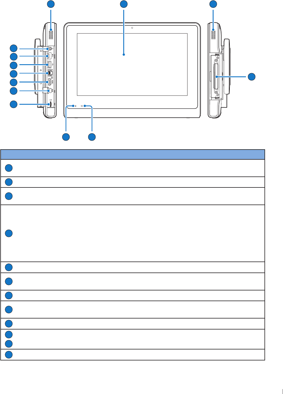
29
eie System Overview
InnoSight Ultrasound System
P6992-4, EN, 16/12/6
System Overview
Front and Side Views
3
54
6
8
10
7
11
12
12
2
9
No. Component Function
1
Touch screen Display system information and allow you to perform operations using
different gestures
2
Speakers Built-in speakers for playing sounds, which are software-controlled
3
Transducer
connection socket Connect a transducer to the system (See page 42)
4
Battery indicator
When the system is turned off and connected to power, the battery
indicator behaves in the following lighting patterns:
Steadily on orange when the battery is charging
Steadily on green after the battery is charged
When the system is turned on and connected to power, the battery
indicator lights off To monitor the battery level, see Battery Status
Icons on page 64
5
Power indicator Blink blue after the system enters Sleep mode (See page 64)
6
MicroSD card slot Insert a microSD card into the microSD card slot to exchange data from/
to the system (See page 39)
7
AU port For use by authorized service personnel only
8
HDMI port Connect the system to an HDMI (High-Definition Multimedia Interface)
device (See page )
9
Ethernet socket Connect the system to an Ethernet-based network (See page 6)
10
USB 2 port Connect the system to USB 2/3 devices, such as keyboards, pointing
devices, or portable storage devices
11
USB 3 port
12
Headphone jack Connect the system to an audio device, such as headphones or speakers
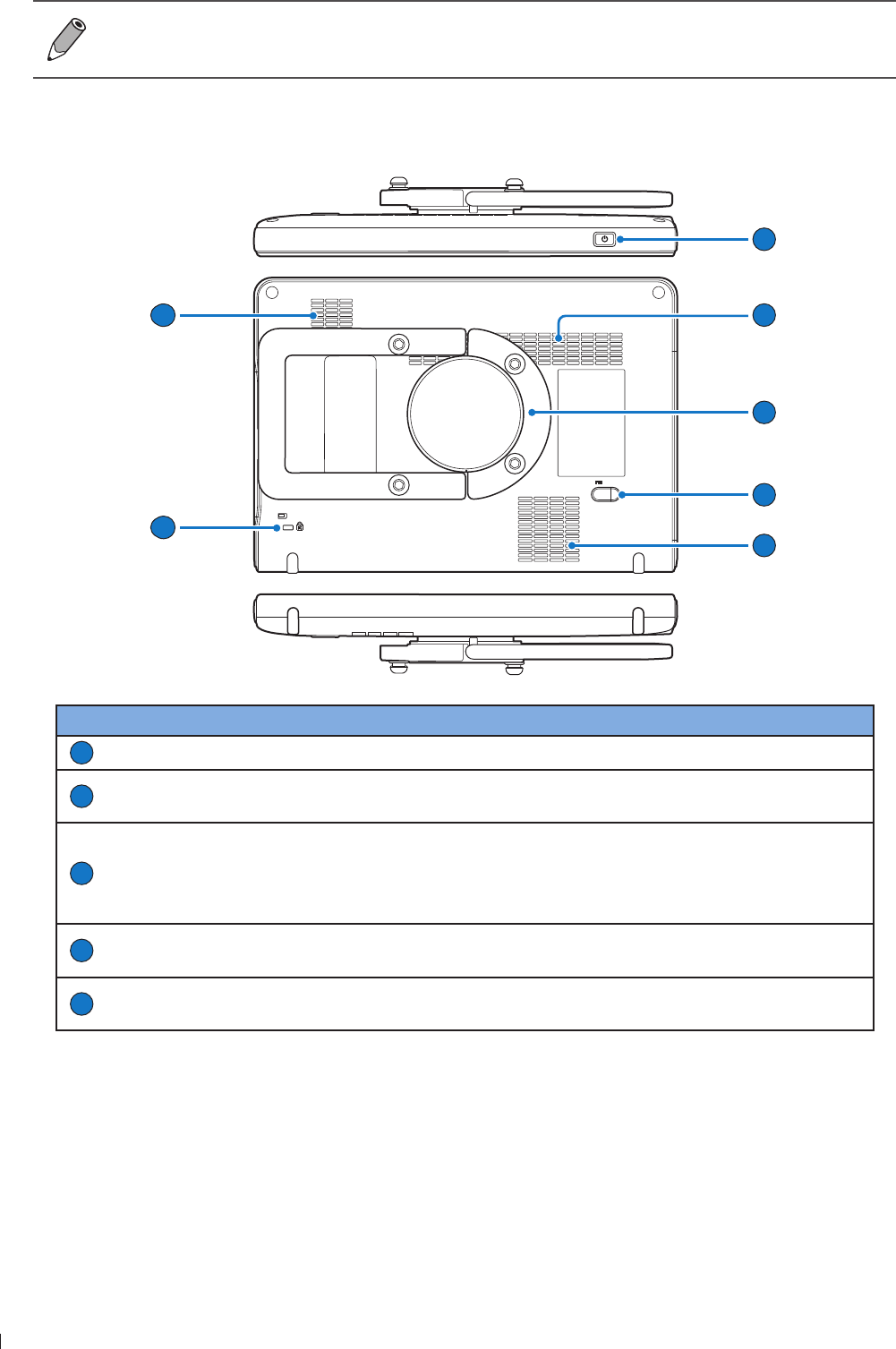
InnoSight Ultrasound System
System Overview eie
3 P6992-4, EN, 16/12/6
The system supports access to only one external storage device at a time If you connect more
than one external storage device, they function in the following priority order: USB 3 USB 2
microSD card
Rear and Top/Bottom Views
17
13
14
15
16
14
14
No. Component Function
13
Power button Press and hold the Power button to turn on/off the system
14
Ventilation slots Release excessive heat during operation to keep the system in a safe
operating temperature
15
Rotating stand
Pull the rotating stand out to sustain the system on a flat surface (See
Using the Stand on page 4)
Can be used as a handle to carry the system around (See Using the
System On The Go on page 43)
16
Power input socket Used to connect the system to power (See Charging the System on
page 41)
17
Anti-theft lock slot Used to lock the system securely to a solid surface to protect it from
theft
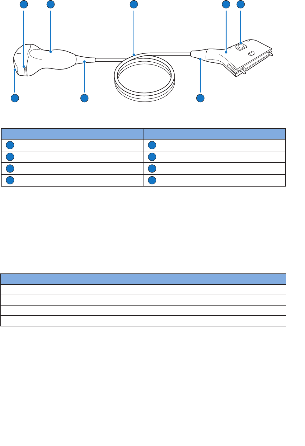
31
eie Transducer Overview
InnoSight Ultrasound System
P6992-4, EN, 16/12/6
Transducer Overview
2
8
3
7
5
1
6
4
Figure 3Transducer overview (Example transducer: C6-2)
No. Component No. Component
1
Orientation marker
2
Transducer handle
3
Transducer cable
4
Transducer connector
5
Release latch
6
Connector strain relief
7
Transducer strain relief
8
Transducer lens
Use only transducers that are approved by Philips for use with the system
Clinical Applications and Transducers
A clinical application, available for one or more transducers, optimizes the system for a specific application
A clinical application consists of exam-specific presets, and the corresponding measurement and calculation
packages
The clinical applications for each transducer available for the system are listed in the following table
Transducer Clinical Applications
C6-2 Abdomen, OB, GYN, Renal, Urology
L12-4 Carotid, Arterial, Venous,Thyroid, Breast, Bowel, MS, Nerve
S4-2 Cardiac
C9-4v OB, GYN, Prostate
For more information, see Indications for Use and Supporting Transducers on page 34
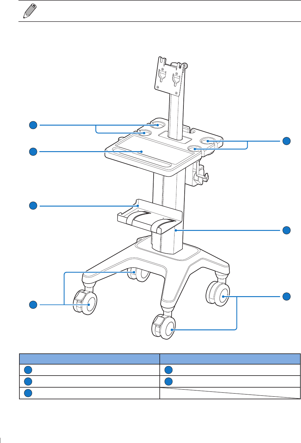
InnoSight Ultrasound System
System Cart Overview eie
32 P6992-4, EN, 16/12/6
System Cart Overview
The system cart is available for purchase as an optional item
Front View
1
1
2
4
3
3
5
No. Item No. Item
1
Transducer/gel holder
2
Cart pillar
3
Caster wheel with brake
4
Printer holder
5
Work table
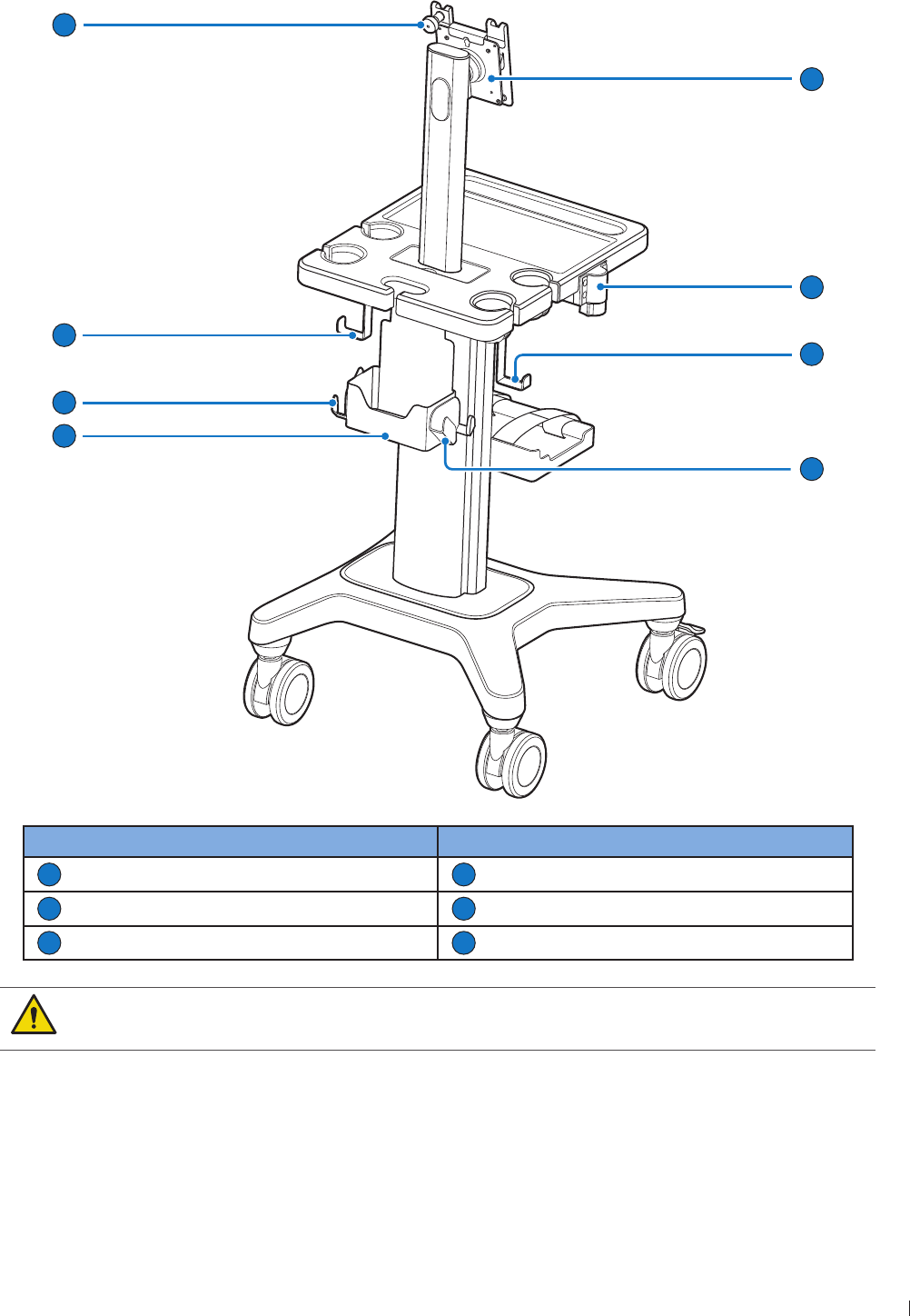
33
eie System Cart Overview
InnoSight Ultrasound System
P6992-4, EN, 16/12/6
Rear View
9
10
6
9
8
10
11
7
No. Item No. Item
6
nurled thumb knob
7
Mount plate
8
Height-adjustment button
9
Cable collector
10
Transducer hanger
11
Rear container
Observe the precautions and warnings listed in Mechanical Safety on page 1 and Moving
the System on page 49 before using the system cart to avoid injury and system failure

InnoSight Ultrasound System
Indications for Use and Supporting Transducers eie
34 P6992-4, EN, 16/12/6
Indications for Use and Supporting Transducers
InnoSight Diagnostic Ultrasound System is a general-purpose ultrasonic imaging instrument intended for
use by a qualified physician for evaluation of Abdomen, Cardiac, Small Organ (breast, testes, thyroid), heart
soft tissue, Peripheral Vascular, Musculoskeletal, Fetal and OB/GYN
The following tables provide Diagnostic Ultrasound Indications for Use Forms for the transducers offered
with the InnoSight Diagnostic Ultrasound System
DIAGNOSTIC ULTRASOUND INDICATIONS FOR USE FORM
System: InnoSight Diagnostic Ultrasound System
Intended Use: Diagnostic ultrasound imaging or fluid flow analysis of the human body as follows:
Clinical application Mode of operation
General
(Track 1 only)
Specific
(Track 1 and 3) 2D M-Mode PW
Doppler
CW
Doppler Color CPA Other
Combined
Tissue
Harmonic
Imaging
Ophthalmic Ophthalmic
Fetal imaging
and others
Fetal N N N N N Note 1 N
Abdominal N N N N N Note 1 N
Intra-operative
Specify
Intra-operative
Neuro
Laparoscopic
Pediatric
Small Organ
(breast, thyroid,
testes)
N N N N N Note 1 N
Neonatal Cephalic
Adult Cephalic
Trans-rectal N N N N N Note 1 N
Trans-vaginal N N N N N Note 1 N
Trans-urethral
Trans-esoph (non-
Card)
Musculoskeletal
(Conventional)
Musculoskeletal
(Superficial)
Intravascular
Other (OB/GYN) N N N N N Note 1 N
Cardiac
Cardiac Adult N N N N N N Note 1 N
Cardiac Pediatric
Intravascular
(Cardiac)
Trans-esoph
(Cardiac)
Intra-cardiac
Other (specify)
Peripheral
vessel
Peripheral Vessel N N N N N Note 1 N
Other (specify)

3
eie Indications for Use and Supporting Transducers
InnoSight Ultrasound System
P6992-4, EN, 16/12/6
N new indication P previously cleared by FDA E added under this appendix
Note 1: Combined modes include: 2DM-Mode 2DPW Doppler 2DColor 2DCPA 2DColorPW
Doppler and 2DCPAPW Doppler
DIAGNOSTIC ULTRASOUND INDICATIONS FOR USE FORM
System: InnoSight Diagnostic Ultrasound System
Transducer: C6-2 (Curved Linear Array 2-6 MHz)
Intended Use: Diagnostic ultrasound imaging or fluid flow analysis of the human body as follows:
Clinical application Mode of operation
General
(Track 1 only)
Specific
(Track 1 and 3) 2D M-Mode PW
Doppler
CW
Doppler Color CPA Other
Combined
Tissue
Harmonic
Imaging
Ophthalmic Ophthalmic
Fetal imaging
and others
Fetal N N N N N Note 1 N
Abdominal N N N N N Note 1 N
Intra-operative
Specify
Intra-operative
Neuro
Laparoscopic
Pediatric
Small Organ
(breast, thyroid,
testes)
Neonatal Cephalic
Adult Cephalic
Trans-rectal
Trans-vaginal
Trans-urethral
Trans-esoph (non-
Card)
Musculoskeletal
(Conventional)
Musculoskeletal
(Superficial)
Intravascular
Other (OB/GYN) N N N N N Note 1 N
Cardiac
Cardiac Adult
Cardiac Pediatric
Intravascular
(Cardiac)
Trans-esoph
(Cardiac)
Intra-cardiac
Other (specify)
Peripheral
vessel
Peripheral Vessel
Other (specify)
N new indication P previously cleared by FDA E added under this appendix
Note 1: Combined modes include: 2DM-Mode 2DPW Doppler 2DColor 2DCPA 2DColorPW
Doppler and 2DCPAPW Doppler

InnoSight Ultrasound System
Indications for Use and Supporting Transducers eie
36 P6992-4, EN, 16/12/6
DIAGNOSTIC ULTRASOUND INDICATIONS FOR USE FORM
System: InnoSight Diagnostic Ultrasound System
Transducer: L12-4 (Linear Array 4-12 MHz)
Intended Use: Diagnostic ultrasound imaging or fluid flow analysis of the human body as follows:
Clinical application Mode of operation
General
(Track 1 only)
Specific
(Track 1 and 3) 2D M-Mode PW
Doppler
CW
Doppler Color CPA Other
Combined
Tissue
Harmonic
Imaging
Ophthalmic Ophthalmic
Fetal imaging
and others
Fetal
Abdominal N N N N N Note 1 N
Intra-operative
Specify
Intra-operative
Neuro
Laparoscopic
Pediatric
Small Organ
(breast, thyroid,
testes)
N N N N N Note 1 N
Neonatal Cephalic
Adult Cephalic
Trans-rectal
Trans-vaginal
Trans-urethral
Trans-esoph (non-
Card)
Musculoskeletal
(Conventional) N N N N N Note 1 N
Musculoskeletal
(Superficial)
Intravascular
Other (OB/GYN)
Cardiac
Cardiac Adult
Cardiac Pediatric
Intravascular
(Cardiac)
Trans-esoph
(Cardiac)
Intra-cardiac
Other (specify)
Peripheral
vessel
Peripheral Vessel N N N N N Note 1 N
Other (specify)
N new indication P previously cleared by FDA E added under this appendix
Note 1: Combined modes include: 2DM-Mode 2DPW Doppler 2DColor 2DCPA 2DColorPW
Doppler and 2DCPAPW Doppler

3
eie Indications for Use and Supporting Transducers
InnoSight Ultrasound System
P6992-4, EN, 16/12/6
DIAGNOSTIC ULTRASOUND INDICATIONS FOR USE FORM
System: InnoSight Diagnostic Ultrasound System
Transducer: S4-2 (Phase Array 64 elements 2-4 MHz)
Intended Use: Diagnostic ultrasound imaging or fluid flow analysis of the human body as follows:
Clinical application Mode of operation
General
(Track 1 only)
Specific
(Track 1 and 3) 2D M-Mode PW
Doppler
CW
Doppler Color CPA Other
Combined
Tissue
Harmonic
Imaging
Ophthalmic Ophthalmic
Fetal imaging
and others
Fetal
Abdominal
Intra-operative
Specify
Intra-operative
Neuro
Laparoscopic
Pediatric
Small Organ
(breast, thyroid,
testes)
Neonatal Cephalic
Adult Cephalic
Trans-rectal
Trans-vaginal
Trans-urethral
Trans-esoph (non-
Card)
Musculoskeletal
(Conventional)
Musculoskeletal
(Superficial)
Intravascular
Other (OB/GYN)
Cardiac
Cardiac Adult N N N N N N Note 1 N
Cardiac Pediatric
Intravascular
(Cardiac)
Trans-esoph
(Cardiac)
Intra-cardiac
Other (specify)
Peripheral
vessel
Peripheral Vessel
Other (specify)
N new indication P previously cleared by FDA E added under this appendix
Note 1: Combined modes include: 2DM-Mode 2DPW Doppler 2DColor 2DCPA 2DColorPW
Doppler and 2DCPAPW Doppler

InnoSight Ultrasound System
Indications for Use and Supporting Transducers eie
3 P6992-4, EN, 16/12/6
DIAGNOSTIC ULTRASOUND INDICATIONS FOR USE FORM
System: InnoSight Diagnostic Ultrasound System
Transducer: C9-4v (Micro-curved Linear Array 4-9 MHz)
Intended Use: Diagnostic ultrasound imaging or fluid flow analysis of the human body as follows:
Clinical application Mode of operation
General
(Track 1 only)
Specific
(Track 1 and 3) 2D M-Mode PW
Doppler
CW
Doppler Color CPA Other
Combined
Tissue
Harmonic
Imaging
Ophthalmic Ophthalmic
Fetal imaging
and others
Fetal
Abdominal
Intra-operative
Specify
Intra-operative
Neuro
Laparoscopic
Pediatric
Small Organ
(breast, thyroid,
testes)
Neonatal Cephalic
Adult Cephalic
Trans-rectal N N N N N Note 1 N
Trans-vaginal N N N N N Note 1 N
Trans-urethral
Trans-esoph (non-
Card)
Musculoskeletal
(Conventional)
Musculoskeletal
(Superficial)
Intravascular
Other (OB/GYN) N N N N N Note 1 N
Cardiac
Cardiac Adult
Cardiac Pediatric
Intravascular
(Cardiac)
Trans-esoph
(Cardiac)
Intra-cardiac
Other (specify)
Peripheral
vessel
Peripheral Vessel
Other (specify)
N new indication P previously cleared by FDA E added under this appendix
Note 1: Combined modes include: 2DM-Mode 2DPW Doppler 2DColor 2DCPA 2DColorPW
Doppler and 2DCPAPW Doppler
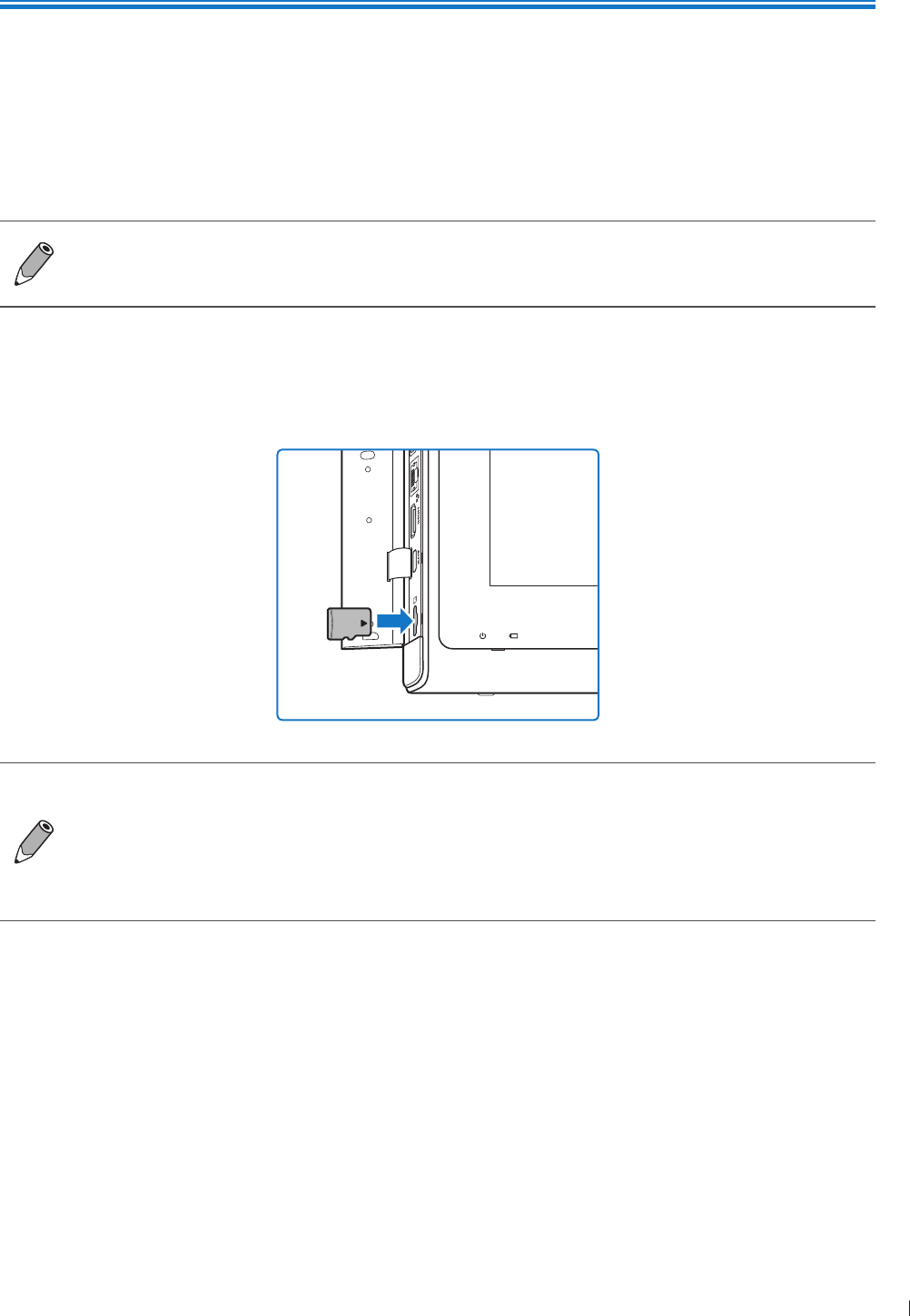
39
epinee Inserting a microSD Card
4
P6992-4, EN, 16/12/6
4 Preparing the System
Follow the information and procedures in this section to help you prepare the system for use
Inserting a microSD Card
Use the microSD card to import/export data to/from your system, such as patient information or user
settings
Supported microSD card format:
SDC (up to 12GB) SDHC Class 1 (up to 32GB)
The microSD card is not supplied with the system
1 Flip the port cover open
2 Align the microSD card with the mark next to the microSD card slot
3 Fully insert the microSD card into the card slot until it clicks into place
You can use the system’s service tools to back up system settings and patient data when the
system is connected to an external storage device For detailed instructions, see Backing Up
System Settings and Patient Data on page 14
The system supports access to only one external storage device at a time If you connect more
than one external storage device, they function in the following priority order: USB 3 USB
2 microSD card
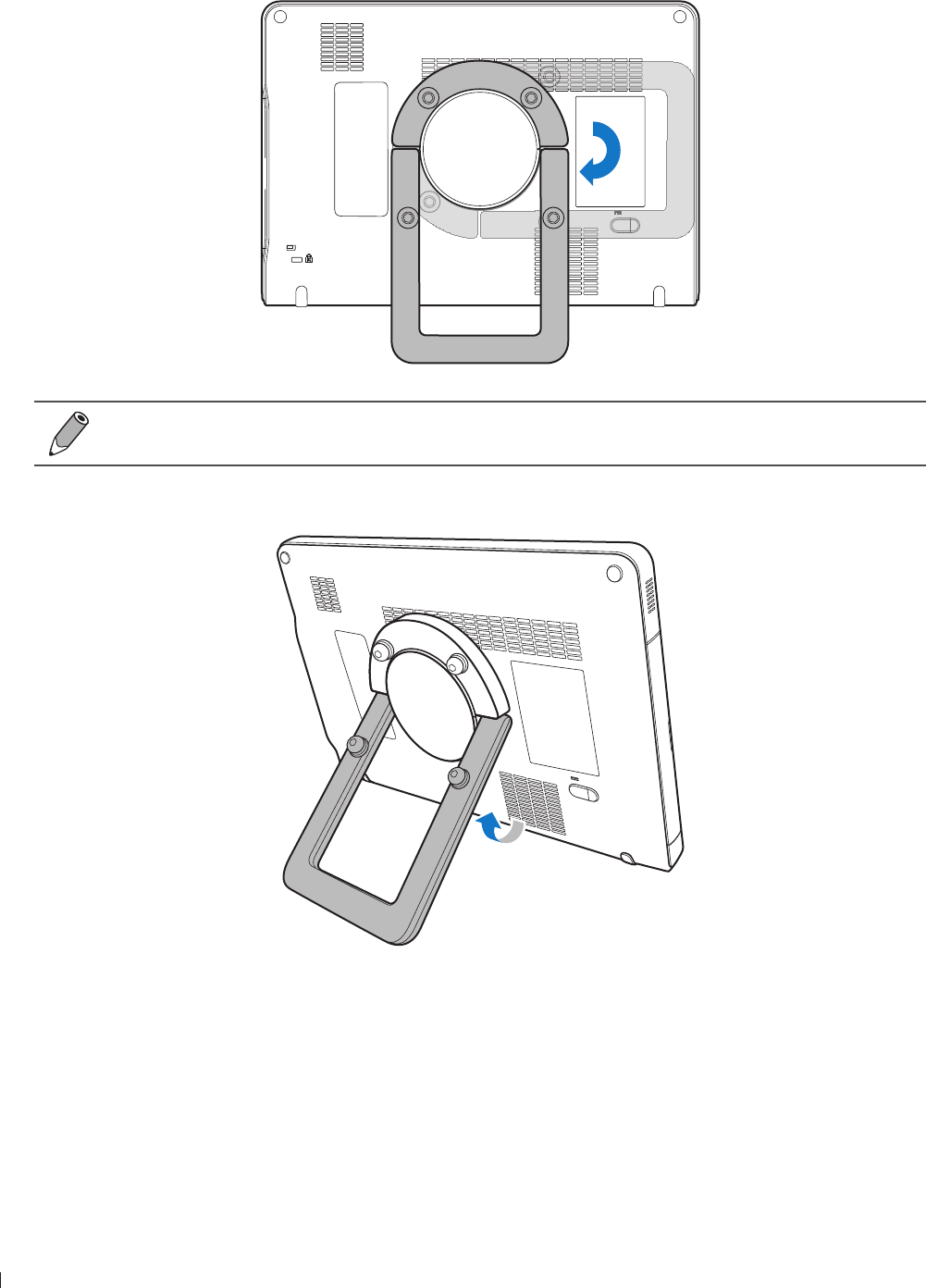
InnoSight Ultrasound System
Using the Stand epinee
40 P6992-4, EN, 16/12/6
Using the Stand
1 Rotate the rotating stand clockwise by 9 degrees
Lay the rotating stand completely flat before rotation
2 Gently pull out the rotating stand to the degree that suits your preferred viewing angle
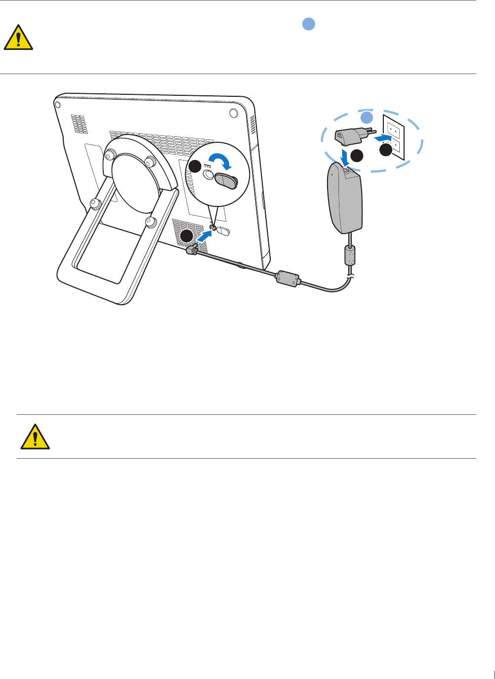
41
epinee Charging the System
InnoSight Ultrasound System
P6992-4, EN, 16/12/6
Charging the System
The system is only partially charged when first unpacked Charge the battery fully for hours before using
the system for the first time
Use only the supplied power adapter and AC plugs for charging
AC plug and electric outlet types vary by country/region
a
Do not try to repair or replace the battery or the power adapter Any attempt to disassemble
the system and the supplied accessories may cause damage to the system or result in personal
injury
2
1
4
3
a
1
1 Lift the protective rubber cover open
2 Connect the power adapter’s connector into the system’s power input socket
3 Insert the matching AC plug fully into the power adapter
4 Plug the AC plug of your power adapter into an electric outlet to start charging The battery indicator
lights up in solid orange
eep good ventilation during charging Do not cover the power adapter with paper or
objects that will reduce cooling
Do not interrupt the connection during charging to avoid possible damage
After the battery is fully charged (around 3 hours), the battery indicator turns green
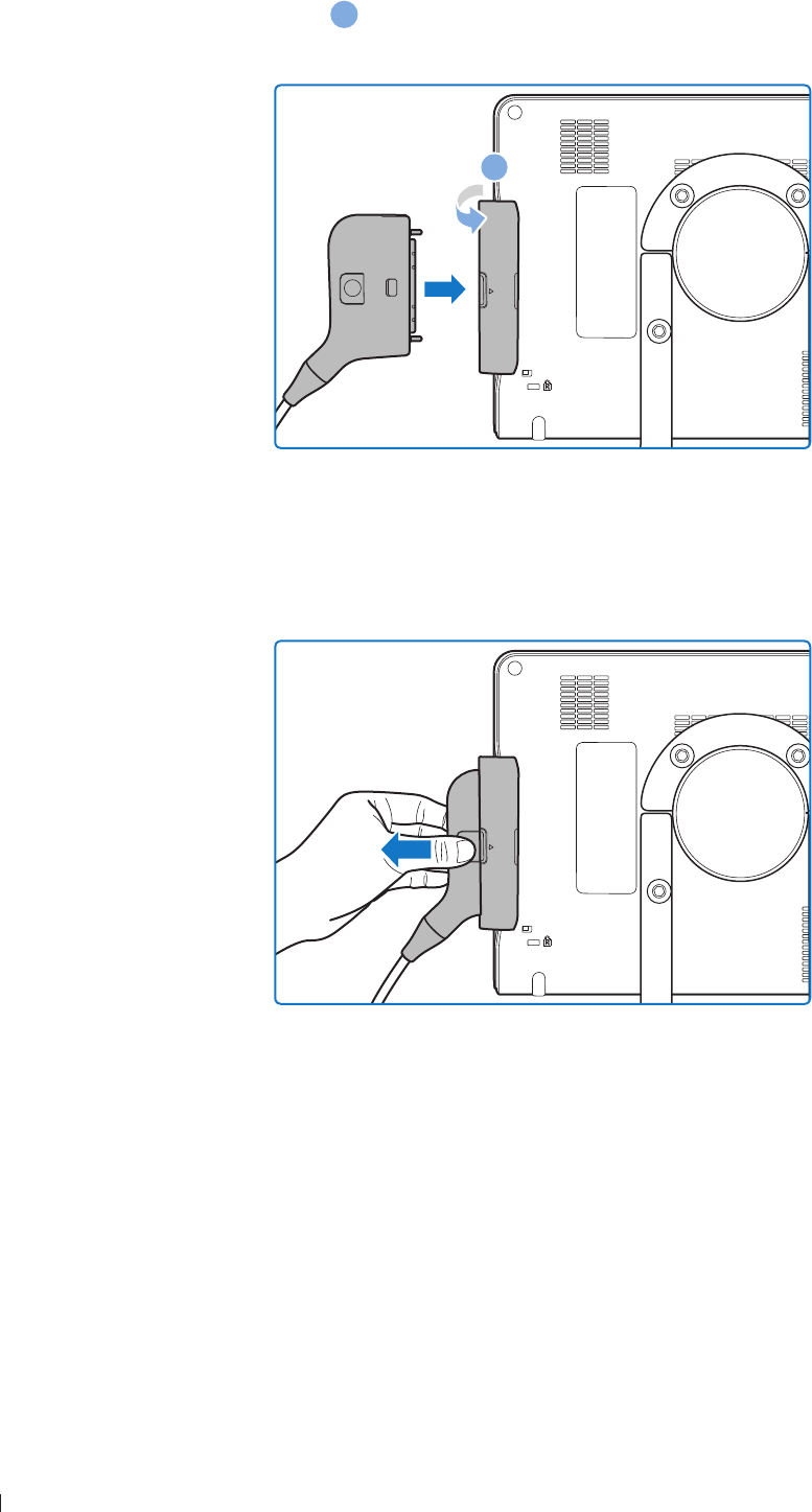
InnoSight Ultrasound System
Connecting the Transducer epinee
42 P6992-4, EN, 16/12/6
Connecting the Transducer
Flip the transducer cover open
a
and insert the transducer carefully into the transducer connection socket
until it is locked in place
a
Removing the Transducer
Press and hold the release latch, and carefully pull out the transducer
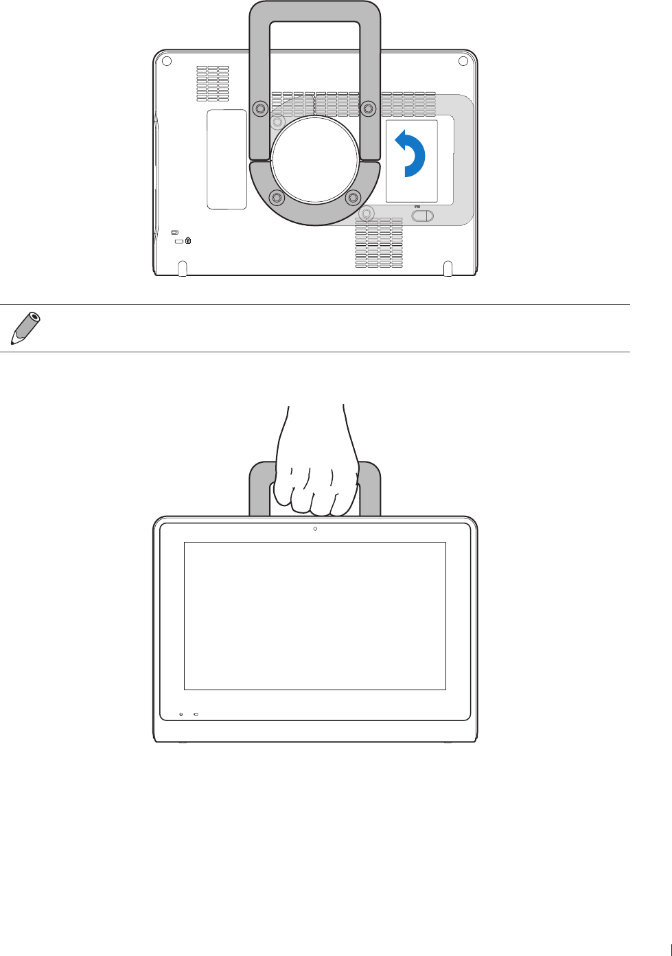
43
epinee Using the System On The Go
InnoSight Ultrasound System
P6992-4, EN, 16/12/6
Using the System On The Go
1 Rotate the rotating stand counterclockwise by 9 degrees
Lay the rotating stand completely flat before rotation
2 Use the rotating stand as a handle to carry the system around
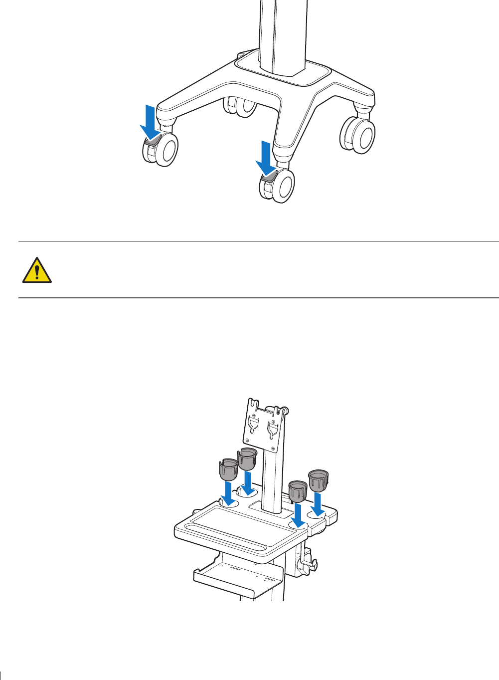
InnoSight Ultrasound System
Using the Wheel Brakes epinee
44 P6992-4, EN, 16/12/6
Using the Wheel Brakes
Use the brakes on the system cart wheels to help keep the cart stationary while in use
To engage the brakes, press down on the lever with your foot
To disengage the brakes, push the levers upward with your foot until they are fixed in place
Never park the system cart on an incline If you park the system on a floor that is tilted 1
degrees or more and set the brakes, one of the braked casters might not be touching the floor,
which can cause the system to move
Observe the precautions and warnings listed in Mechanical Safety on page 1
Placing the Transducer Holder
Place the transducer holders evenly onto the slots on the system cart and gently push them in until they are
fixed in place
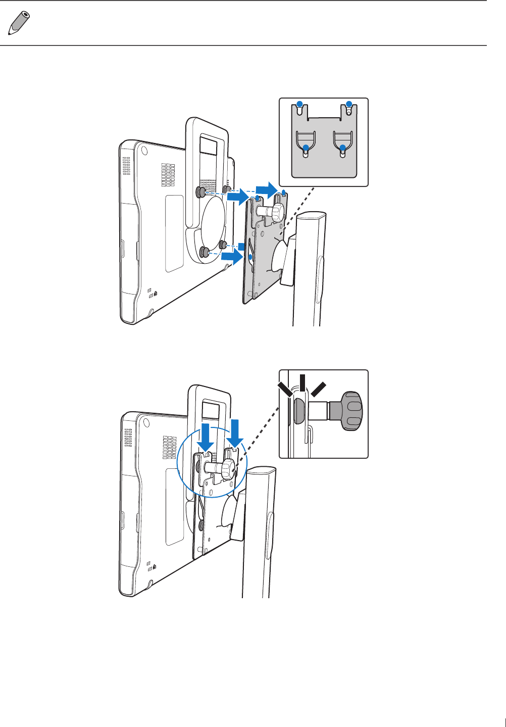
4
epinee Mounting the System to the System Cart
InnoSight Ultrasound System
P6992-4, EN, 16/12/6
Mounting the System to the System Cart
The system cart is available by separate purchase
Before mounting the system to the system cart, ensure that the caster wheels are locked in
place, and the rotating stand is fixed as a handle (See page 43)
1 Hold the system firmly and position it precisely to the front of the mount plate on the cart where the
four screws on the back of the system and the hole patterns of the plate meet
2 Attach the system fully onto the plate until you hear a click sound, indicating that it is locked in place
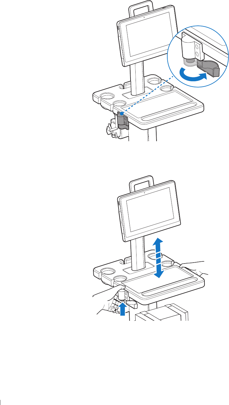
InnoSight Ultrasound System
Adjusting the System Cart Height epinee
46 P6992-4, EN, 16/12/6
Adjusting the System Cart Height
Adjust the height of the system cart to suit different operators and operating positions
1 Open the protective cover
2 Press and hold the height adjustment button to loosen the cart pillar Without releasing the button,
slide the cart pillar up and down until the desired height is reached
3 Release the button to lock the pillar in place
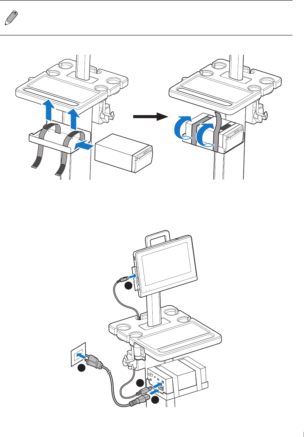
47
epinee Connecting an External Printer
InnoSight Ultrasound System
P6992-4, EN, 16/12/6
Connecting an External Printer
Before connecting the system to an external printer, turn off the system and disconnect the
power adapter from the power outlet
External printers are available by separate purchase For a list of supported printers, see
Supported External Printers on page
Before connection, secure your printer onto the printer holder with the straps
1 Insert one end of an USB cable into your printer’s USB port
2 Insert the other end of the USB cable into the system’s USB port
3 Insert the DC output connector of the power cord into the power socket of the printer
4 Plug the power cord into an power outlet
2
1
3
4
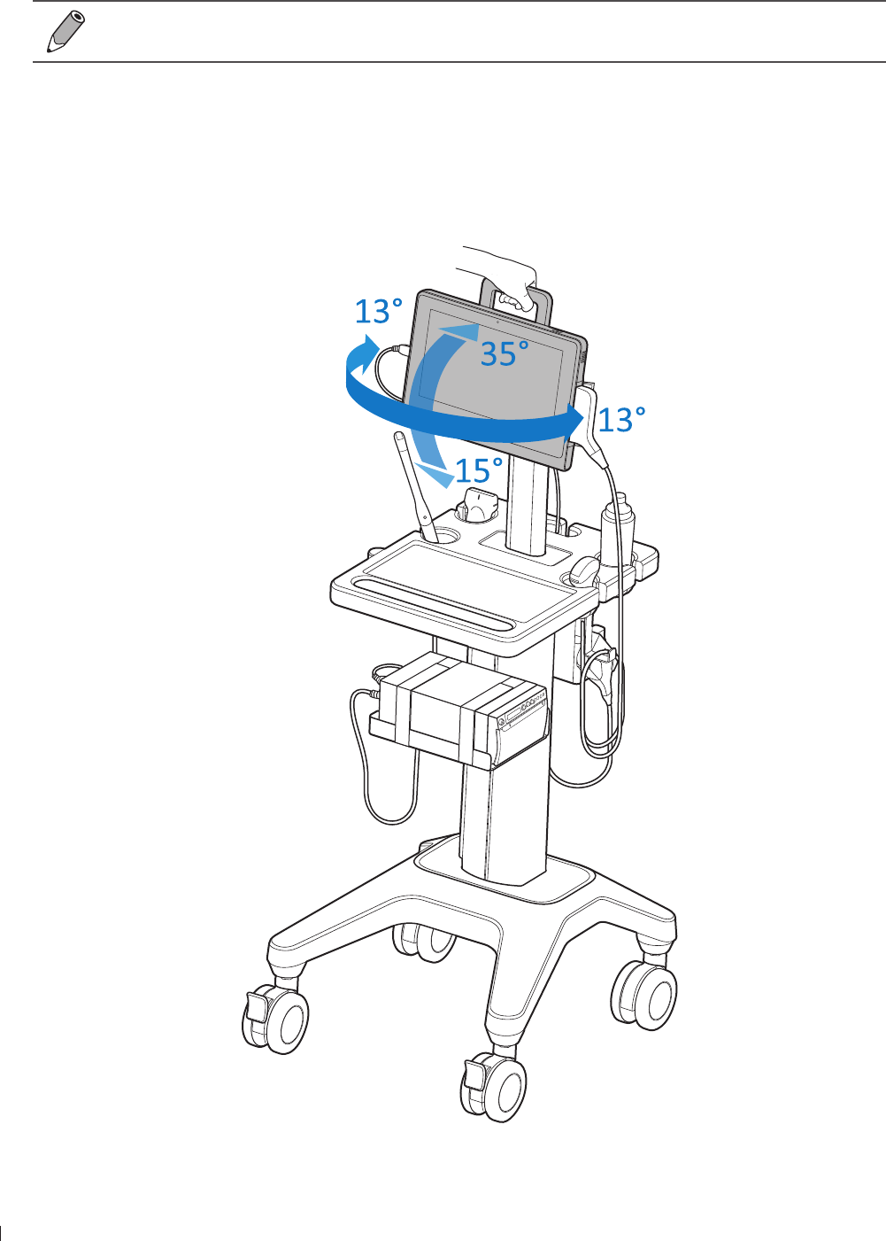
InnoSight Ultrasound System
Tilting the System epinee
4 P6992-4, EN, 16/12/6
Turn on the printer, then turn on the system The system installs the printer drivers automatically
6 After successful installation of the new printer drivers, on the system imaging screen, go to Menu
Settings Print and select the printer name The printer is now ready for use
See your printer documentation included in the sales package for detailed information on
connections and settings
Tilting the System
Your system, while mounted on the system cart, can be rotated and tilted to reach various viewing angles
Hold the rotating stand as a handle to rotate the system
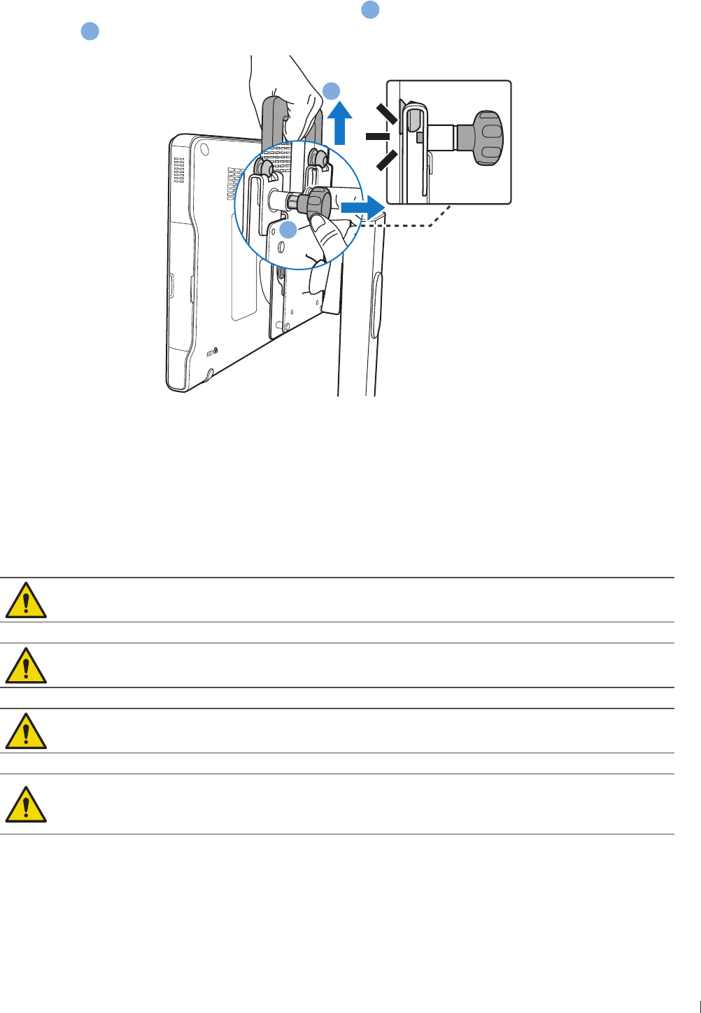
49
epinee Unmounting the System From the System Cart
InnoSight Ultrasound System
P6992-4, EN, 16/12/6
Unmounting the System From the System Cart
Pull out the knurled thumb knob to unlock the system
a
, and simultaneously lift the system from the
mount plate
b
a
b
Moving the System
Before moving the system mounted on the system cart, secure all cables, transducers, and accessories so
that they do not interfere with the caster wheels
Observe the precautions and warnings below and listed in Mechanical Safety on page 1 before moving
the system mounted on a cart
Ensure that the cables for all patient-applied parts are secure before moving the system
Position external peripheral devices away from the system Ensure that they are secure Do not
stack them on the system
When transporting the system in a vehicle, avoid exposing the monitor to direct sunlight Exposure
to direct sunlight can permanently damage the monitor
If system operation is abnormal after you move or transport the system, contact your Philips
representative immediately System components are installed securely and can withstand
considerable shock, but excessive shock can cause a system failure
1 Ensure the system is mounted and locked firmly on the system cart
2 Disengage the wheel brakes
3 Move the cart using the handle at the front of the cart
InnoSight Ultrasound System
Outputting the System Display to an HDMI-Enabled TV or Monitor epinee
P6992-4, EN, 16/12/6
Outputting the System Display to an HDMI-Enabled TV or Monitor
1 Insert one end of an HDMI cable to the system’s HDMI port Ensure that the arrow side faces up
2 Insert the other end of the HDMI cable to your HDMI-enabled TV’s or monitor’s HDMI port
3 Connect the TV or monitor to power
4 On the TV or monitor, select the proper input source
See the documentation of your HDMI-enabled television or monitor for detailed information on
connections and settings
Supported External Printers
You can connect an external printer to your system
For thermal printers:
Use only the printer listed here with your system
Printer type Printer manufacturer and model
number
Support USB
printing
Support network
printing
Black-and-white (thermal)
image printers Sony UP-9MD Yes No
For report printers:
To print out ultrasound images through USB ports, select printers equipped with PostScript3
language emulation
To print out ultrasound images through network connection, select printers that support network print
protocols of Raw Port/Port 91/Port 91 Direct Mode
Images printed on a report printer are intended only for reference and should not be used for
diagnostic purposes
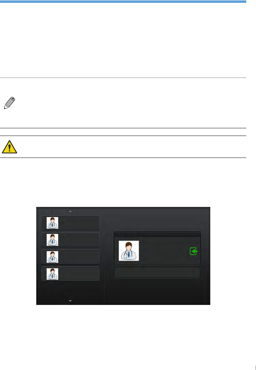
51
inee Turning On/Off the System
5
P6992-4, EN, 16/12/6
5 Using the System
Before performing an ultrasound exam, understand and learn the features of the system
Turning On/Off the System
Press and hold the Power button to turn on the system The system enters the user login screen after
system startup
Press and hold the Power button until the Power off menu appears on the screen, then touch OK to turn
off the system
If the system is turned off abnormally, powering on the system the next time will take longer
than usual for a system hardware check
If the system does not respond to any operations, press and hold the Power button to
forcefully turn off the system
As the number of files saved in the system storage increases, the time it takes to power on
the system will take longer than before Consider backing up files and freeing up disk space
regularly or when you are informed to do so (See Managing Disk Space on page 64)
If an error message occurs after system startup, follow the on-screen instructions to fix the
problem If the problem persists, contact technical support (See Customer Service on
page 3)
Logging Into the System
When data security is enabled, you must log into the system before you are able to view or load patient
files
USER1
USER2
USER3
USER4
Administrator Start as a guest
Selected User
Figure 4User login screen
InnoSight Ultrasound System
Logging Into the System inee
52 P6992-4, EN, 16/12/6
Creating a New Administrator Account
1 After system startup, the default user account with administrative privileges appears on the screen To
begin the first-time-logging-in process, touch the account name, enter the default password and touch
Login
Default User ID: SiteAdmin
Default Password: System’s serial number
To check your system’s serial number:
On the system imaging screen, touch Menu > Settings > About
Refer to the system label on the back of the system
Each time after a fresh installation or restoring the system to its factory state, the system
requires logging in using the default site administrator credentials
2 Enter your personal credentials to create a new site administrator account, and touch OK The default
site administrator account will then be deleted automatically
Logging into the administrator account enables full access to complete safety settings, but not
operations To perform exams and functions, the user logged in needs to be a registered user
To enable this role, check Registered User
3 Follow the instructions in each section to set up the security policies (See page 12) Touch Save to
save the settings
If you choose to start the system as a guest, only restricted operations can be performed To
return to the user login screen at any time, touch Menu > Security > Go to Login Screen
Adding a New User Account
Continue logged in as the administrator to have access to adding new users
1 Touch Menu > User Management
2 Touch Add User Enter personal credentials to create a new user account, and touch OK
If you wish to enable this user as a second administrator with access to security settings, check
Site Administrator
3 The user account is added with default security policies To add more users, repeat step 1-2
To protect user security, the next time the operator logs in as the new user, he or she is required
to change the password
Switching Users
If you are on the user settings screen, touch first to log off current user and enter the user
login screen
On the user login screen, touch the desired user from the user list on the left, the selected user with its user
ID appears on the right Touch , enter the password and touch Login
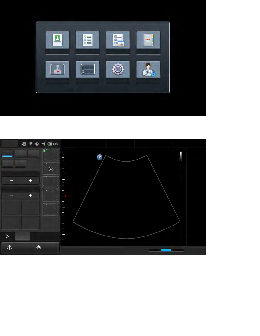
3
inee Launching the Main Screen
InnoSight Ultrasound System
P6992-4, EN, 16/12/6
Managing User Settings
The users without administrative privileges can modify personal credentials as well as limited security
settings
To modify personal credentials, touch Menu > Security > User Edit
To set an automated logout after a specified period of inactivity, touch Menu > Security >
Security Policies
Launching the Main Screen
After successfully logging in as a registered user, one of the following main screens appears
If no transducer is connected, the system enters the system menu screen
Patient Worklist Exam List Report
Preset Review Settings Security
No probe is connected.
If a transducer is connected, the system enters the real-time 2D imaging screen (default)
2D Color PW
M CPA
Focus8.0
Dyn Range78
THI Full Screen
Dual Toggle
Freeze Acquire
Fn Key iScan TGC Home
2D
Menu
End Exam
Pen Res
Abdomen
12/5/2016 08:56 AM
C6-2
MI 0.72
TIS 0.02
32 Hz
16.0 cm
2D
Gen
Gn 44
DR 78
1/ 0/ 1
3/ 0/ 6
3
5
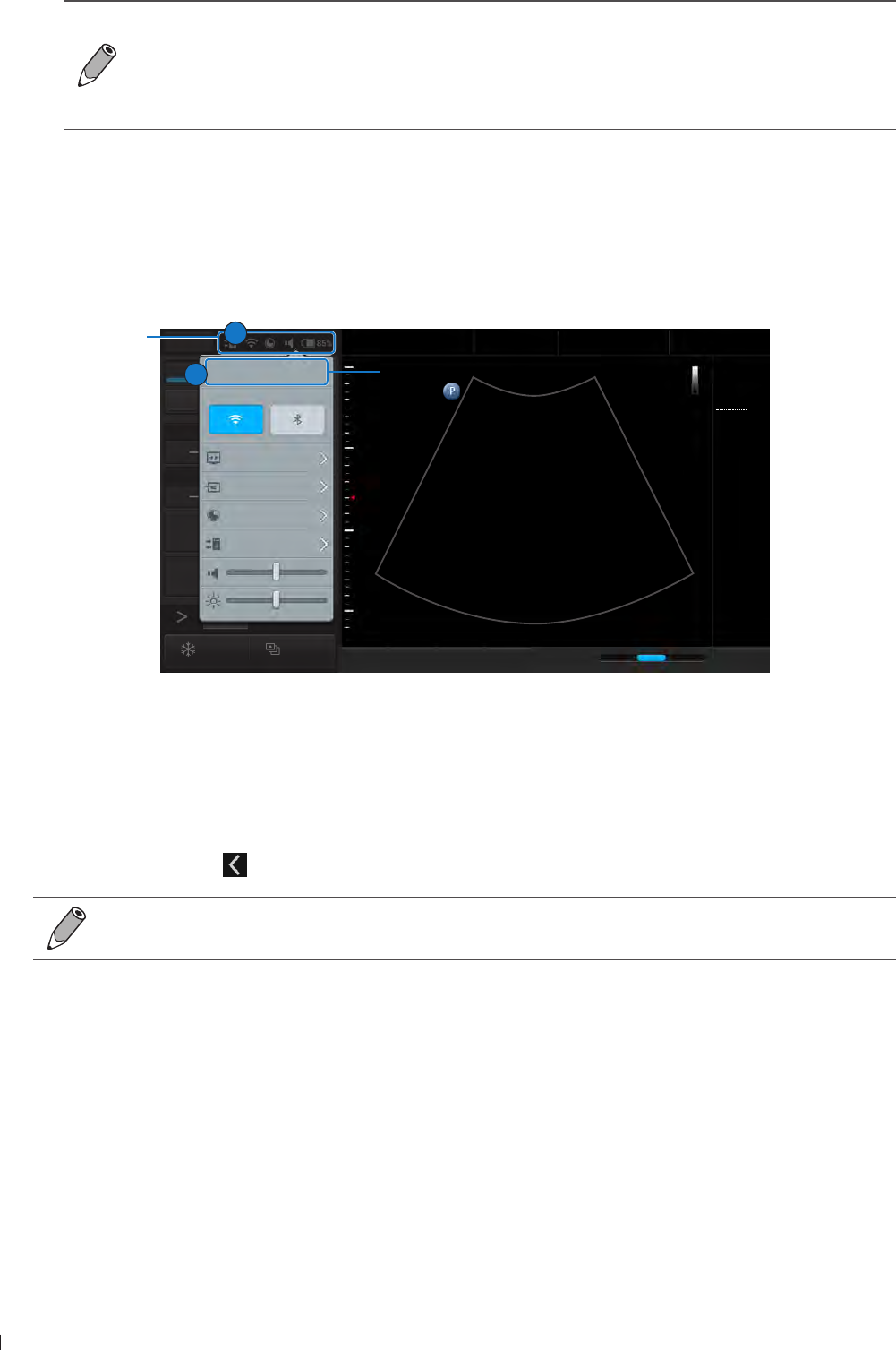
InnoSight Ultrasound System
Setting the System Time and Date inee
54 P6992-4, EN, 16/12/6
If a transducer is connected and the system displays the message No probe is connected,
remove then re-connect the transducer If the system still cannot detect the transducer, turn
off the system Wait for a few seconds and restart the system
You can choose the screen to enter after starting and logging in the system (with the
transducer connected) Go to Menu > Settings > Workflow > Screen after Enter Ultrasound
Setting the System Time and Date
Managing pertinent patient data and scanning results require accurate system time and date After
logging in the system for the first time, set current time and date based on your location The system then
maintains time and date settings even when the system is turned off and disconnected from power
2D Color PW
M CPA
Focus8.0
Dyn Range78
THI Full Screen
Dual Toggle
Freeze Acquire
Fn Key iScan TGC Home
2D
Menu
End Exam
Pen Res
Abdomen
12/5/2016 08:56 AM
C6-2
MI 0.72
TIS 0.02
32 Hz
16.0 cm
2D
Gen
Gn 44
DR 78
1/ 0/ 1
3/ 0/ 6
1
5
8:56 AM12/6/2016
Monday
Long press button to launch settings
page.
Cast Display Off
Lan Connected
Storage Usage 85%
DICOM Connected
Touch to set current time and date.
System
toolbar
2
1
Figure 5Setting the system time and date
1 Touch anywhere on the system toolbar to open the system tools menu (See page 61)
2 Touch the time date section Set time/Set date
To set the time, scroll to select the hours, minutes, and am or pm
To set the date, scroll to select the date, month and year
3 Touch Done Touch to leave the setting
Check and correct current system time and date based on your location every month to ensure
the accuracy
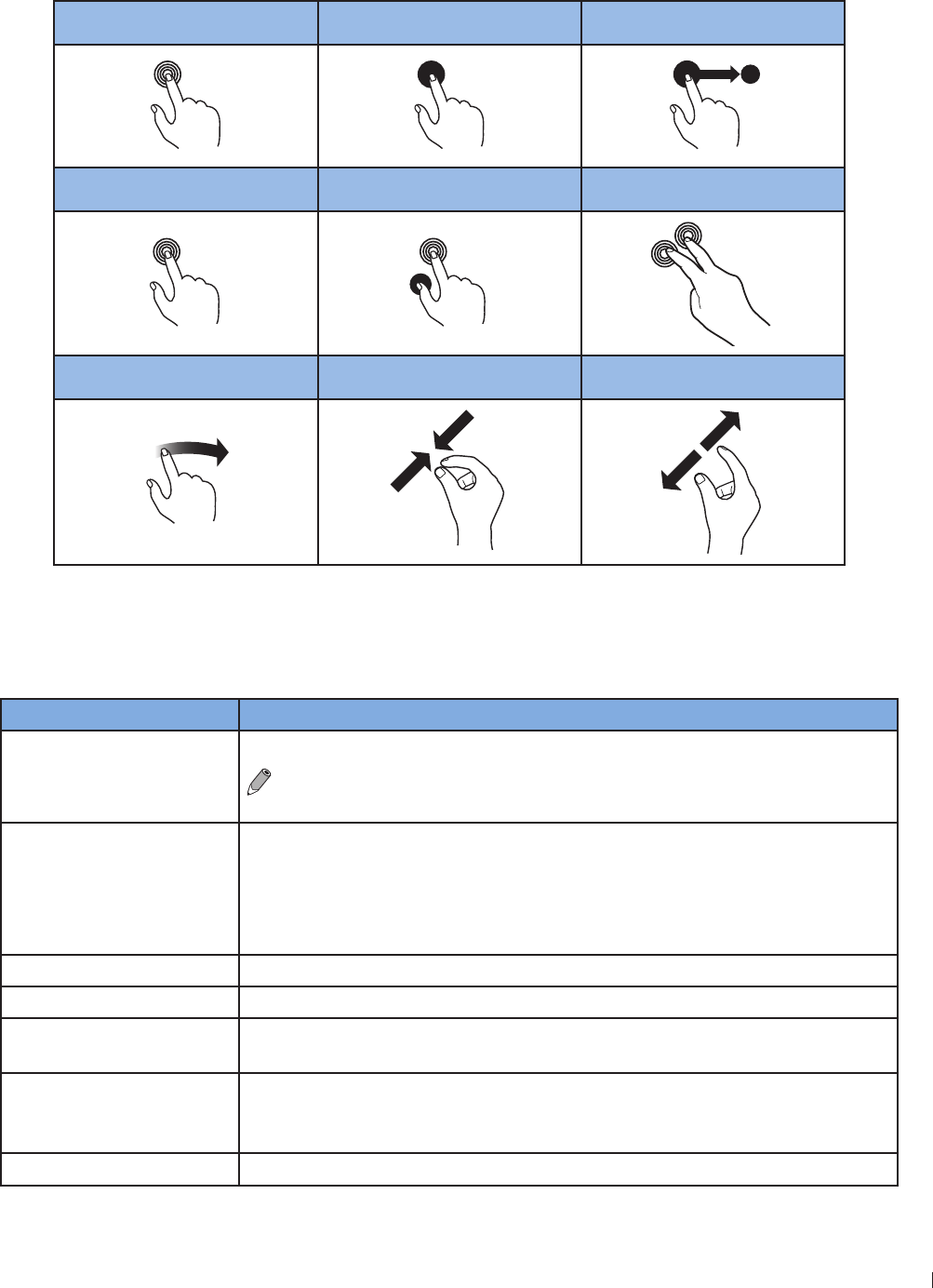
55
inee Controlling the System
InnoSight Ultrasound System
P6992-4, EN, 16/12/6
Controlling the System
The system requires operations with multi-touch controls by finger movements called gestures
Alternatively, you can add pointing or input devices by connecting them to the USB ports on the system
Touch Touch and Hold Drag
Double-Tap Press and Tap Two-Finger Tap
x2
Flick Pinch Spread
Figure 6Gestures
Gestures for Controlling the Real-time/Frozen Imaging Screens
Action Gesture
Toggle between Real-time
and frozen imaging screens
Double-tap on the scan area
To use this gesture, go to Menu > Settings > General >
(Enable freeze gesture) > Yes
Save a single image/cine
loop
(Available in full screen mode only)
Touch and hold on the scan area of the real-time/frozen imaging screens to
save a cine loop/single image
If you play an image loop on the frozen imaging screen, touch and hold on
the scan area saves a cine loop
Zoom/unzoom Spread two fingers apart/pinch two fingers together
Move the zoomed image Touch and hold the zoomed image, and drag to move the image
Move and resize ROI Touch inside the ROI and drag to move it Touch on the four corners of the
ROI and drag to resize it
Move the BDM/
annotation/arrow
indicators
Touch and hold the indicator, and drag to move it
Scroll the thumbnail list Flick vertically on the thumbnail area to scroll through the thumbnail list
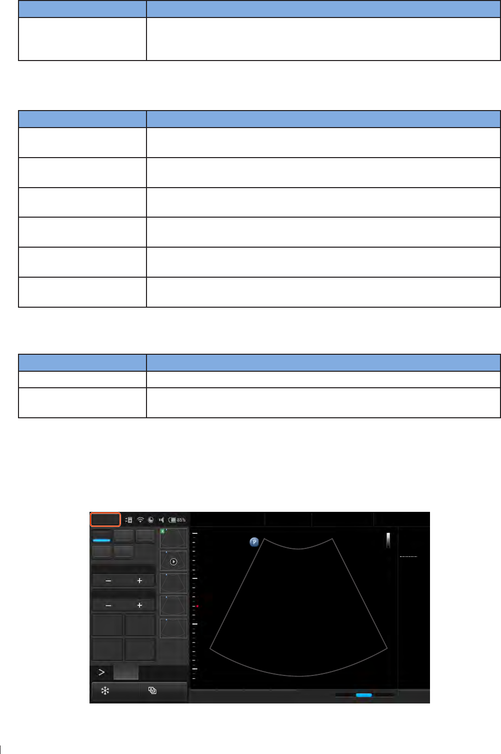
InnoSight Ultrasound System
Setting the System Language inee
56 P6992-4, EN, 16/12/6
Action Gesture
Display the second control
panel page/Return to the
first control panel page
On the control panel area, flick right to display the second page, flick left
to return to the first page (See Switching the Control Panel Pages on
page 62)
Gestures for Controlling the Real-time Imaging Screen
Action Gesture
Adjust depth Flick vertically on the scan area to increase (flick down) or decrease (flick up)
depth
Adjust gain Flick horizontally on the scan area/time series window to increase (flick right)
or decrease gain (flick left)
Adjust the sample volume
size
1 Touch and hold one finger on the scan line
2 Flick another finger up or down
Move the scan line/sample
volume Touch the scan line or sample volume, and drag to move it
Adjust the PW/CW
correction angle
1 Touch and hold one finger on the scan line
2 Flick another finger to the left or right
Adjust the PW/CW baseline 1 Touch and hold on the baseline
2 Flick vertically to change the baseline position
Gestures for Controlling the Frozen Imaging Screen
Action Gesture
Play/pause image loops (Available in full screen mode only) Two-finger tap on the scan area
Scroll frames (Available in full screen mode only) Flick horizontally on the scan area/time
series window to scroll through the image frames/waveforms
Setting the System Language
To set the system language you are using, touch Menu > Settings > General > Language, and the system
reboots automatically for the localized language to take effect
2D Color PW
M CPA
Focus8.0
Dyn Range78
THI Full Screen
Dual Toggle
Freeze Acquire
Fn Key iScan TGC Home
2D
Menu
End Exam
Pen Res
Abdomen
12/5/2016 08:56 AM
C6-2
MI 0.72
TIS 0.03
76 Hz
16.0 cm
2D
Gen
Gn 43
DR 78
1/ 0/ 1
1/ 0/ 4
1
5
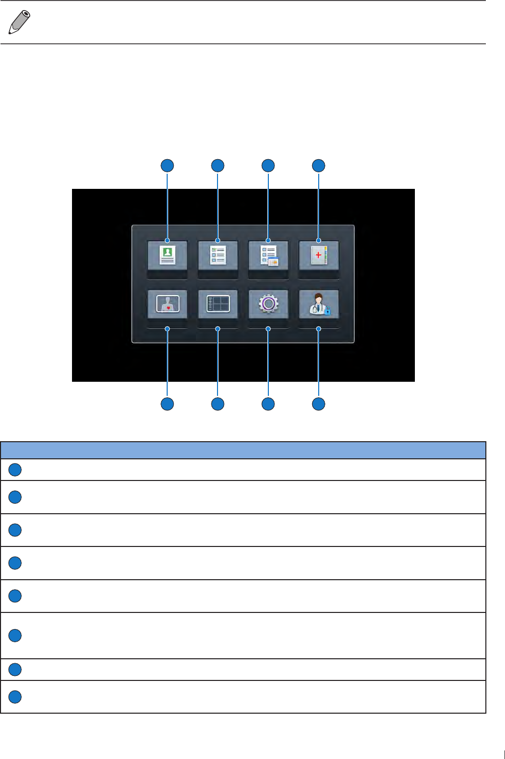
57
inee Identifying the Main Screen Layout
InnoSight Ultrasound System
P6992-4, EN, 16/12/6
If you are unsure of a function displayed in localized languages, switch the system language back
to English, and check again the function you want to use If the problem persists, contact technical
support (See Customer Service on page 3)
Identifying the Main Screen Layout
System Menu Screen
Touch Menu to display the following system menu screen Touch an icon to perform its function
Patient Worklist Exam List Report
Preset Review Settings Security
1
2
3
4
5
6
7
8
Figure 7System menu screen
No. Function Description
1
Patient Edit current or add new patient information
2
Worklist Load the DICOM Modality Worklist (MWL) that contains patient information as well
as the requested procedure electronically via the MWL query
3
Exam List View a list of patients with their exam results You can proceed with unfinished
exams/reviews, or export exams according to the selection criteria all at once
4
Report Display exam information including patient data, exam type, study specific data,
comments and saved ultrasound images
5
Security Manage users and permissions to control access to ePHI (Electronic Protected
Health Information) data on the system and the system features
6
Settings
Customize the system based on the operator’s habitual needs
Use the service tools to update software, backup/restore data or examine the
system functionality (See Servicing your system on page 12)
7
Review View, add annotations and measurements to, and export a saved exam
8
Preset Select the predefined preset compatible with the connected transducer for
optimized image control settings
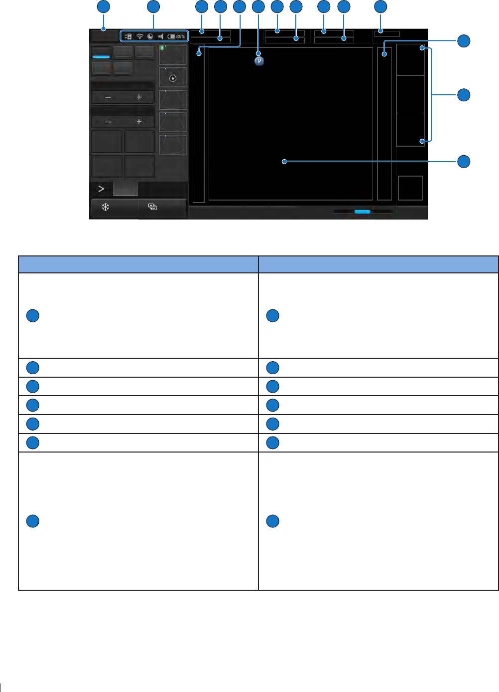
InnoSight Ultrasound System
Identifying the Main Screen Layout inee
58 P6992-4, EN, 16/12/6
Imaging Screen (Real-time)
With the transducer connected correctly, the system enters the real-time imaging screen each time after
pressing the Home button
2D Color PW
M CPA
Focus8.0
Dyn Range78
THI Full Screen
Dual Toggle
Freeze Acquire Fn Key iScan TGC Home
2D
Menu
End Exam
Pen Res
Transducer
MI
TIS
1
2
13
7
14
6
5
12
4
3
8
9
10
11
5
Figure 8Real-time imaging screen (example)
No. Function No. Function
1
System menu button
Enter the system menu screen
2
System toolbar
Display information about current battery
level, volume, system storage, and network
connection status Touch anywhere on the
system toolbar to open the system tool menu
for system configuration (See page 61)
3
Patient name
4
Patient ID
5
Depth scale
6
Transducer orientation icon (See page 3)
7
Patient age/gender/DOB (date of birth)
8
Application name
9
Current date and time
10
User name
11
Institution name
12
Grayscale/spectrum wedge
13
Scan properties display area
Display information about the current scan
14
Ultrasound imaging area
Display the 2D imaging window in all scan
modes By default, the top area is close to the
region located near the transducer surface
(near field) When scanning in M-Mode/
PW Doppler/Triplex modes, the Time Series
window displays under the 2D imaging
window The time increases from left to right
and re-starts from the left again The imaging
area displays as common usage
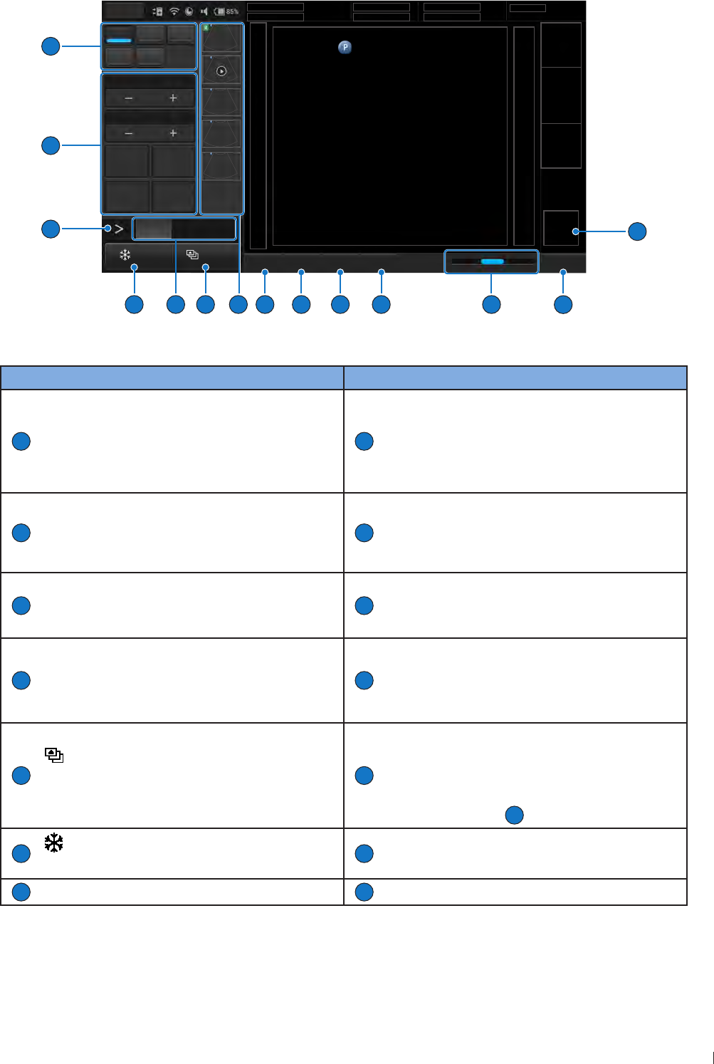
59
inee Identifying the Main Screen Layout
InnoSight Ultrasound System
P6992-4, EN, 16/12/6
2D Color PW
M CPA
Focus8.0
Dyn Range78
THI Full Screen
Dual Toggle
Freeze Acquire Fn Key iScan TGC Home
2D
Menu
End Exam
Pen Res
Transducer
MI
TIS
16
17
15
18
19
20
21
22
25
26
27
28
24
23
5
Figure 9Real-time imaging screen (example)
No. Function No. Function
15
ROI (region of interest) area
Use the Zoom function to zoom in and pan
across the current image
16
End Exam button
Close the current exam for the current
patient, and start a new exam for the next
patient All the value settings adjusted during
this exam will be stored automatically
17
Res (High Resolution): Drag the cursor to
the right for a clearer yet superficial image
Pen (Deep Penetration): Drag the cursor to
the left for a deeper yet less clear image
18
Home button
Return to the real-time imaging screen
19
TGC (Time Gain Compensation)
Slide any of the TGC sliders to adjust the gain
for the desired section of the 2D image
20
iScan button
Optimize the image quality during a real-time
scan
21
Fn Key button
Assign this button as a shortcut to perform a
function
22
Thumbnail area
Thumbnails of the scanned images/loops that
are saved Flick vertically to scroll through the
list
23
Acquire button
Save a default set of image frames as a loop
to the system hard drive
24
Scan mode (image control) buttons
When using duplex or triplex modes, touch
the scan mode (image control) buttons here
to display and adjust its corresponding image
control settings
27
25
Freeze button
Freeze the current scan
26
Open the next page of the image control
settings (See page 6)
27
Image control settings (See page 9)
28
Scan mode buttons
The system does not allow acquiring images/loops with no patient name and ID A temporary patient
name will be added if you proceed with saving
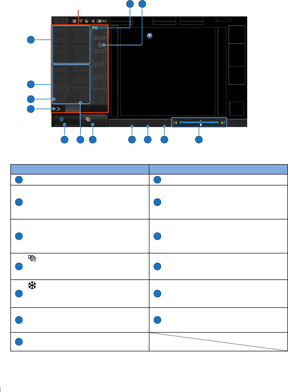
InnoSight Ultrasound System
Identifying the Main Screen Layout inee
60 P6992-4, EN, 16/12/6
Imaging Screen (Frozen)
During an exam, touch Freeze to review all the ultrasound images stored in the cine buffer frame by frame,
or play back these frames in a continuous loop You can also measure, calculate and add annotations to the
frozen images or loops
Control panel
Distance Depth
Ellipse Trace
Angle Calc
IMT Erase Meas
Annot Label
Arrow Body Mark
Erase Annot
Report Play
Freeze Acquire Fn Key Set Start Set End Home
Menu
End Exam
1 30
Transducer
MI
TIS
2D
10
4
6
7
9
3
5
2
12
11
5
1
8
13
Figure 10Frozen imaging screen (example)
No. Function No. Function
1
This image is added to a report
2
Image loop
3
The progress bar
Used to track the frames (in a continuous
image loop) just scanned and the number of
the current frame
4
Home button
Return to the real-time imaging screen
5
Set End button
During playback of the image loop, touch this
button to set the end point of the image loop
6
Set Start button
During playback of the image loop, touch this
button to set the start point of the image
loop
7
Acquire button
Save a frozen image from an image loop to
the system hard drive
8
Play button
Review the image loop just scanned Touch
repeatedly to start/pause the playback
9
Freeze button (Enabled)
Touch this button again to return to the real-
time scan
10
Open the next page of the image control
settings (See page 62)
11
Add annotations, including arrows, texts and
body marks, to the current image using the
virtual keyboard
12
Perform measurements and calculations on
the current image
13
Report button
Generate a report from the current scan
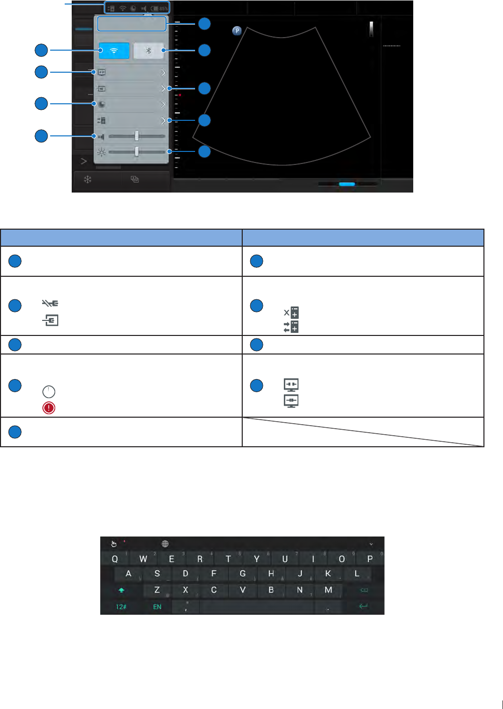
61
inee Identifying the Main Screen Layout
InnoSight Ultrasound System
P6992-4, EN, 16/12/6
System Tools
Touch anywhere on the system toolbar to open the system tools menu Touch an item to adjust its setting
2D Color PW
M CPA
Focus8.0
Dyn Range78
THI Full Screen
Dual Toggle
Freeze Acquire
Fn Key iScan TGC Home
2D
Menu
End Exam
Pen Res
Abdomen
12/5/2016 08:56 AM
C6-2
MI 0.72
TIS 0.03
76 Hz
16.0 cm
2D
Gen
Gn 43
DR 78
1/ 0/ 1
1/ 0/ 4
1
5
8:56 AM 12/5/2016
Monday
Long press button to launch
settings page.
Cast Display Off
Lan Connected
Storage Usage 85%
DICOM Connected
9
8
7
6
1
2
3
4
5
System
toolbar
Figure 11System tool menu
No. Function No. Function
1
Set current date and time (See page 4)
2
Enable/disable the Bluetooth function (See
page 66)
3
Manage the LAN connection (See page 6)
: LAN Disconnected
: LAN Connected
4
Check and manage outgoing queues to the
DICOM server (See page 66)
: DICOM Disconnected
: DICOM Connected
5
Adjust the brightness
6
Adjust the volume
7
Display the percentage of the system storage
used (See page 64)
: Storage usage empty
: Storage usage full
8
Cast the system screen to an external display
: Cast Display Off
: Cast Display On
9
Enable/disable the WiFi function (See
page 6)
Virtual eyboard
Whenever you need to enter text in a text field, simply touch the field, and a virtual keyboard appears on
the lower part of the screen
Touch a letter to enter text when finishing inputs, touch Done
Figure 12Virtual keyboard
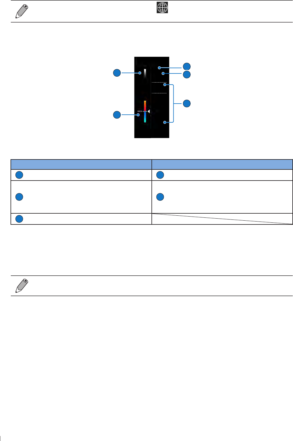
InnoSight Ultrasound System
Switching the Control Panel Pages inee
62 P6992-4, EN, 16/12/6
To switch the keyboard input language, touch on the virtual keyboard and select your target
language
Scan Properties Display
The imaging window includes a text display information about the current scan
1
C6-2
MI 1.04
TIS 0.28
12 Hz
12.0 cm
2D
Gen
Gn 41
Color
Gen
Gn 47
1/ 1/ 5
Filter 20.0Hz
15
-15
1
2
4
5
3
Figure 14Scan properties display (example)
No. Function No. Function
1
Transducer type
2
Thermal index/Mechanical index
3
Depending on the transducer connected and
the scan mode selected, corresponding scan
parameters are displayed (See Chapter
Using Image Controls on page 9)
4
Color/CPA wedge
5
Grayscale wedge
Switching the Control Panel Pages
Use the virtual buttons or gestures to switch the control panel pages
The functions available on the control panel vary, depending on the scan mode and the transducer
connected
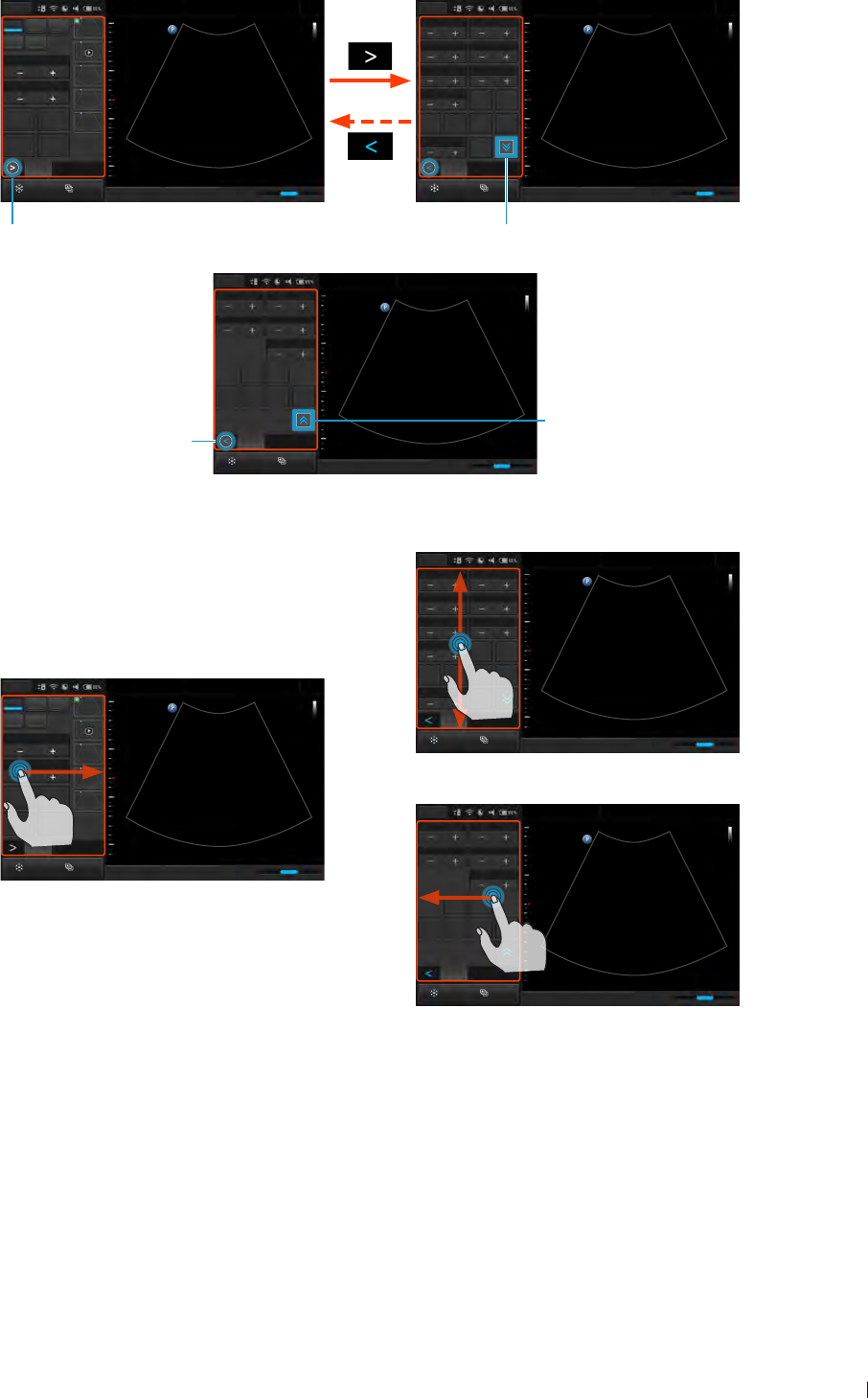
63
inee Managing the System Power
InnoSight Ultrasound System
P6992-4, EN, 16/12/6
Use buttons:
Menu Abdomen
12/5/2016 08:56 AM
Persist4XRES1
Gray Map1Chroma0
Focal Zone1Focal Span1
Steer
Trap Density
High
L/R U/D FQBeam
1
SonoCT
0
ENV Angle
ENV
2D
Freeze Acquire
Fn Key iScan TGC Home
Pen Res
1
2D Color PW
M CPA
Focus8.0
Dyn Range78
THI Full Screen
Dual Toggle
5
2D
Freeze Acquire
Fn Key iScan TGC Home
Pen Res
Menu Abdomen
12/5/2016 08:56 AM
1
Touch to open the next page (page 2)
Page 1
Touch to display more functions (page 3)
Page 2
Depth16.0 Gain39
Sector Width256 Sector Pos
Power80.0
Body
Mark Zoom
Annot Label Arrow Erase
Annol
Menu Abdomen
12/5/2016 08:56 AM
2D
Freeze Acquire
Pen Res
1
Fn Key iScan TGC Home
Touch to return to
the first page (page 1)
Touch to return to
the previous page
(page 2)
Page 3
Use gestures:
Depth16.0 Gain39
Sector Width256 Sector Pos
Power80.0
Body
Mark Zoom
Annot Label Arrow Erase
Annot
Menu Abdomen
12/5/2016 08:56 AM
2D
Freeze Acquire
Pen Res
1
Fn Key iScan TGC Home
Page 2, 3
Menu Abdomen
12/5/2016 08:56 AM
Persist4XRES1
Gray Map1Chroma0
Focal Zone1Focal Span1
Steer
Trap Density
High
L/R U/D FQBeam
1
SonoCT
0
ENV Angle
ENV
2D
Fn Key iScan TGC Home
Pen Res
1
Page 2, 3
2D Color PW
M CPA
Focus8.0
Dyn Range80
THI Full Screen
Dual Toggle
2D
Freeze Acquire
Fn Key iScan TGC Home
Pen Res
Menu Abdomen
12/5/2016 08:56 AM
1
5
Page 1
Managing the System Power
The system receives its power from the power adapter whenever it is connected to the system and starts
charging the battery, unless the battery is fully charged already Battery remains charging even when
the system is turned off, as long as the adapter is connected to the system and to AC power The system
can also operate on battery power The battery status icon (See page 64) along with the percentage of
battery power remaining are shown on the system toolbar (See page 61) Always monitor the power level
of the battery when you operate the system on battery power
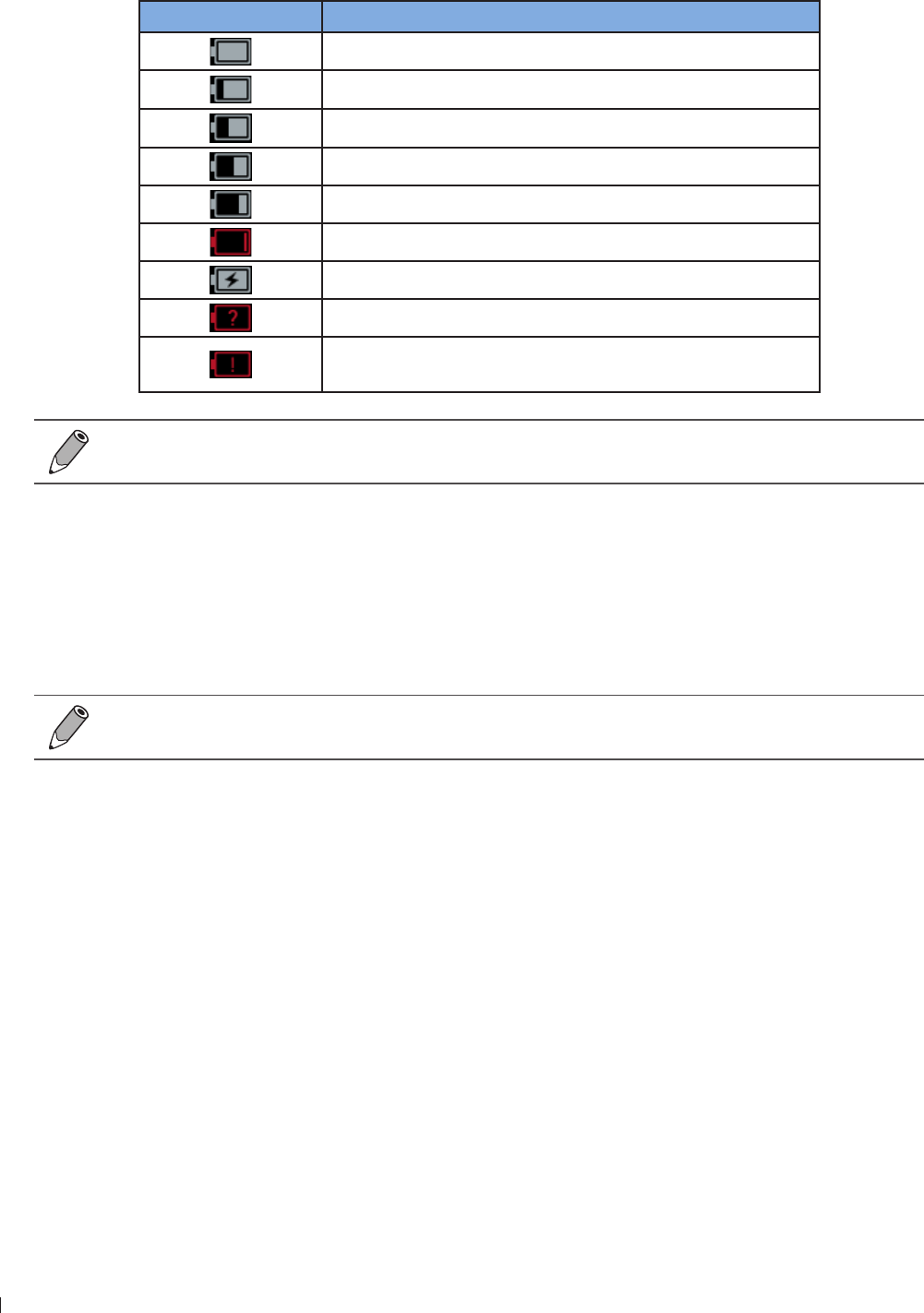
InnoSight Ultrasound System
Managing Disk Space inee
64 P6992-4, EN, 16/12/6
Battery Status Icons
The battery level is indicated by icons shown on the system toolbar
Battery status icon Meaning
The battery is fully charged
The battery is to 99 charged
The battery is 6 to 9 charged
The battery is 4 to 9 charged
The battery is 2 to 39 charged
The battery is critically low
The battery is charging
The battery cannot be identified
Battery temperature is too high or too low and the battery
stops charging
When the battery level reaches a critically low state, the system shuts down automatically
Sleep Mode
Sleep mode is a low-power mode that conserves battery power and allows quick startup of the system
It should be used only for short periods of time, such as when you transport the system between exam
locations
To enter/exit Sleep mode, press the Power button
If automatic logoff is enabled, the current user is logged off when the system enters Sleep mode
Managing Disk Space
Always beware of the amount of free space in the system storage If the disk space on the system drive is
full, the system cannot acquire images To check the system storage used, open the system tool menu and
watch the number of percentage next to Storage Usage
The system sends warning messages when its available disk space reaches any of the following level:
Low on disk space: The disk space available for storing images is low Delete some stored exams to
ensure that there will be enough room for new images
Critically low on disk space: The disk space available for storing images is critically low Immediately
delete some stored exams to free up your disk space
Disk Full: No disk space is available and no images can be saved You must delete stored exams in order
to have space for acquiring new images
To free up storage space, go to Menu > Settings > Exam, and delete stored exams in the appointed number
of weeks
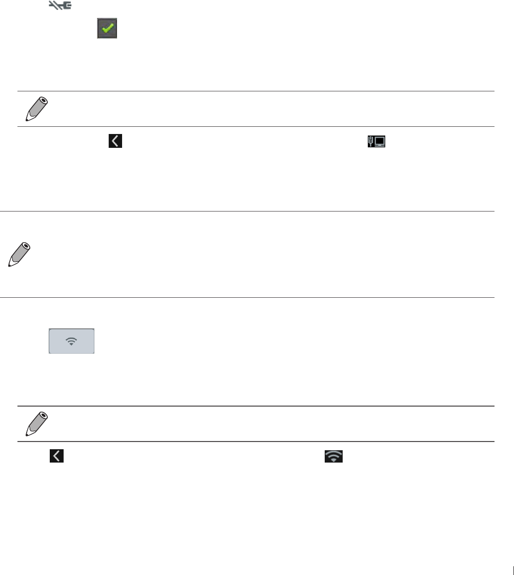
65
inee Network Configuration
InnoSight Ultrasound System
P6992-4, EN, 16/12/6
Network Configuration
The system network is configured from the system tool menu (See page 61) The configuration
information for the system includes the IP address, port number, and other attributes required for
transmitting images and other study data across a network The system network must be configured before
you use either the standard network support or the capabilities available through the DICOM networking
options
Connecting the System to the Network by Ethernet
1 Connect one end of the provided network connection cable to the wall receptacle for your network
2 Connect the other end of the cable to the Ethernet socket on the system
3 On the imaging screen, open the system tools menu (See page 61)
4 Touch to go to its settings
Check Ethernet to enable the Ethernet function If your system does not use Dynamic Host
Configuration Protocol (DHCP) to specify the addresses of domain name servers, continue to the next
step
6 Touch Ethernet configuration Touch Static IP and configure the DNS settings
Consult your network administrator about the appropriate settings
Touch Save Touch to leave the setting If the connection is successful, appears on the system
toolbar
Connecting the System to the Wireless Network
Wireless connection quality can be affected by many factors The system may experience a
connection interruption while a network job is in progress If this occurs, the job remains in the
job queue When the connection is restored, the system resumes the job automatically
The system supports the following wireless security standard: WEP, WPA/WPA2 and WPS It is
your responsibility to configure the wireless network security mechanisms that are compatible
with your network
1 Open the system tools menu (See page 61)
2 Touch to enable the wireless network function, then touch and hold this button to go to its
settings
3 On the available network list, select an access point on an existing wireless network with your DICOM
server, and enter the required settings
Consult your network administrator about the appropriate settings
4 Touch to leave the settings If the connection is successful, appears on the system toolbar
indicating the network strength
InnoSight Ultrasound System
DICOM Configuration inee
66 P6992-4, EN, 16/12/6
Connecting the System to a Bluetooth Device
You can connect the system to another pointing or input device via Bluetooth
Using features requiring a Bluetooth connection may consume more battery power
To extend battery life between charges, turn off Bluetooth when not using it
Maximum distance between two connected Bluetooth devices cannot exceed meters
1 Open the system tools menu (See page 61)
2 Touch to enable the Bluetooth function, then touch and hold this button to go to its settings
3 The system scans for and displays the IDs of available Bluetooth devices within range
To make your system visible to nearby devices, touch your system’s name so that it shows
Visible to all nearby Bluetooth devices
4 Touch the ID of the Bluetooth device to pair with it
Confirm the passkey that appears and touch Pair On the other Bluetooth device, accept the identical
passkey for pairing
6 Touch to leave the settings Once your system pairs with the device, appears on the system
toolbar, and they stay paired until you unpair them
Unpair a Bluetooth Device
Touch beside the connected device you want to unpair, and touch Unpair
DICOM Configuration
The system conforms to the Digital Imaging and Communications in Medicine (DICOM) standard DICOM
format is used for patient studies that are transferred among PACS, which make up a hospital information
management system, and for studies that are accessed by physicians at remote viewing stations
The DICOM networking option settings are usually obtained from a network administrator
Before DICOM configuration, ensure that the system is successfully connected to a wireless or
wired network
To configure DICOM settings, touch Menu > Settings > DICOM
Modality Interface
DICOM standard DICOM conformance statements for Philips products are available at this website:
wwwhealthcarephilipscom/main/about/connectivity/dicomconformancemainwpd
Adding Servers
1 Select a storage/worklist SCP and touch Edit
Storage SCP: Used to take responsibility for and provide receipt of content sent by the system
Worklist SCP: Contain scheduled patient procedure data and is used to import the data into the
patient information form
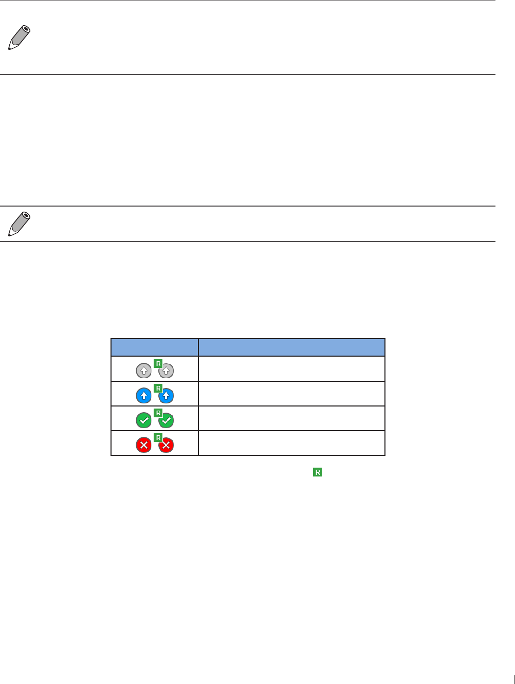
67
inee DICOM Configuration
InnoSight Ultrasound System
P6992-4, EN, 16/12/6
2 Assign a name to the server and enter it in the Name field
3 Enter the IP Address, Port and AE Title specified by your network administrator in the respective fields
4 To test the server connection, touch Test in the Echo Test section A verification message confirms a
successful connection within a few seconds
Repeat step 1-4 to add more servers based on your needs
If you add a second storage SCP, when you export an exam or an image/video to the DICOM
server, two tasks are created in the outgoing queues
To start exams by loading patient information in a worklist, you need to configure the worklist
SCP first
Consult your network administrator about the appropriate settings
Local Host
In the Local Host section, touch Edit
The system’s default Name and IP Address, if connected successfully to the network, display in the
respective fields
In the AE Title field, enter the application entity title of your system, which identifies you as the sender and
must be unique on its network
Consult your network administrator about the appropriate settings
Managing Outgoing Queue
When you export an exam or an image/video to the DICOM server, you can monitor its status in the
outgoing queue The system provides three ways of exporting the exam For more information, see
Exporting the Exam on page
Task status icon* Description
Upload is pending
Upload is processing
Upload is complete
Upload failed
If you export an exam as a report, the task status icon includes
In the Outgoing Queue section, touch Edit
To re-send the task to the DICOM server, touch Retry
To cancel the ongoing task, touch Stop
To clear all tasks from the outgoing queue, touch Clear all

InnoSight Ultrasound System
68 P6992-4, EN, 16/12/6

69
einnx Starting a New Exam
6
P6992-4, EN, 16/12/6
6 Performing an Exam
To perform an exam, complete the general procedure:
1 Start an exam It can be a new exam, or a previously saved/paused exam
To start a new patient exam, add a new patient (Patient screen)
To load a work list (Worklist screen)
To resume a previously saved/paused exam (Exam List screen)
2 Select an exam type and preset (Preset screen)
3 Start real-time imaging (Imaging screen (Real-time))
4 Set the transducer orientation (See page 3)
Select a scan mode (See page 3) and adjust image controls (See page 9)
6 When the desired anatomy is shown, freeze the image (Imaging screen (Frozen))
Add annotations (See page 6) and measurements (See page )
Save or print the image (See page 2)
9 (Optional) Review the images (See page 3), generate a report and export the exam (See page )
1 End the exam (See page )
Refer to the following sections for detailed instructions
Starting a New Exam
The system allows skipping entering patient information if you need to start the ultrasound exam
immediately However, the system will add a temporary name/ID automatically if you wish to save the
images and cine loops You can enter the patient screen to complete the patient information during or after
the exam
To avoid confusion and to generate reports, define the patient within the system before scanning
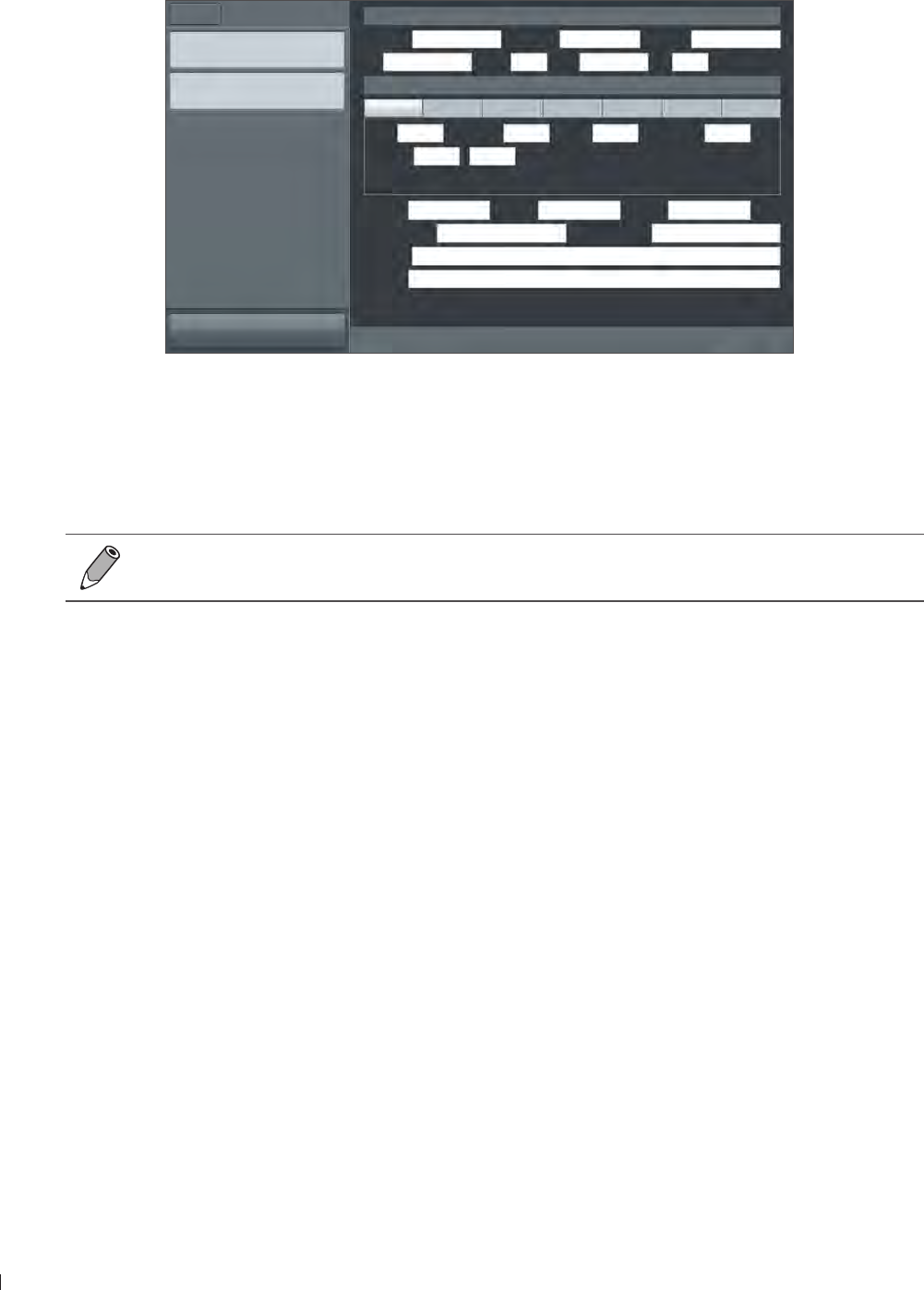
InnoSight Ultrasound System
Adding a New Patient einnx
70 P6992-4, EN, 16/12/6
Adding a New Patient
1 On the imaging screen, touch Menu > Patient
Patient information
Last Name Middle Name First Name
ID Gender DOB Age
Exam Information
Abdomen Cardiology GYN OB Small Part Urology Vascular
Height cm Weight kg BSA m2Heart Rate bpm
Blood Press / mmHg
Accession Institution Operator
Referring Physician Interpreting Physician
Description
Comment
New Patient
Start Exam
Menu Patient
Home Previous End Exam
Figure 15Patient screen
2 Touch New Patient Enter the patient information as much detailed as possible:
»Touch in a text entry field, and use the virtual keyboard to input contents
»Touch Next on the keyboard to go to the next field
»Touch Done on the keyboard The patient information is saved automatically
To create a valid patient profile, at least the patient’s Last Name and ID number should be
filled in
3 To start scanning the patient, touch Start Exam
Updating Patient Information
1 During real-time scanning, touch Menu > Patient Existing information of the current patient displays on
the patient screen
2 Enter the new information in the desired fields
3 The patient information is saved automatically Proceed with real-time scanning of this patient by
touching Start Exam
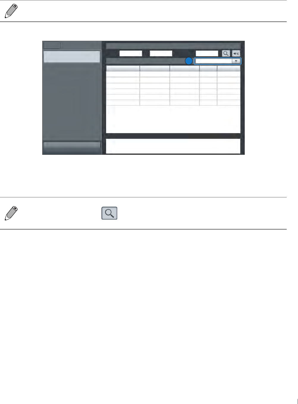
1
einnx Loading a Worklist
InnoSight Ultrasound System
P6992-4, EN, 16/12/6
Loading a Worklist
The system conforms with the Digital Imaging and Communications in Medicine (DICOM) standard, which
is the industrial standard for the communication and management of patient data between devices in the
hospital You can load patient information in a worklist via the DICOM server
For more information on configuring DICOM settings, see DICOM Configuration on page 66
1 On the imaging screen, touch Menu > Worklist
Name ID Accession# Gender DOB
Start Exam
Menu Worklist
Home Previous
Query Worklist
Name ID Accession#
Worklist: 0 2016.07.06 All
Details
2
Figure 16Worklist screen
2 Select the number of patients to scan on the worklist from the drop-down menu
3 Select a patient, then touch Start Exam to start scanning
To scan patients following a specific rule, enter the query criteria in any of the Name / ID /
Accession# fields, and touch to start the query Patients matching the query criteria will be
listed on the screen
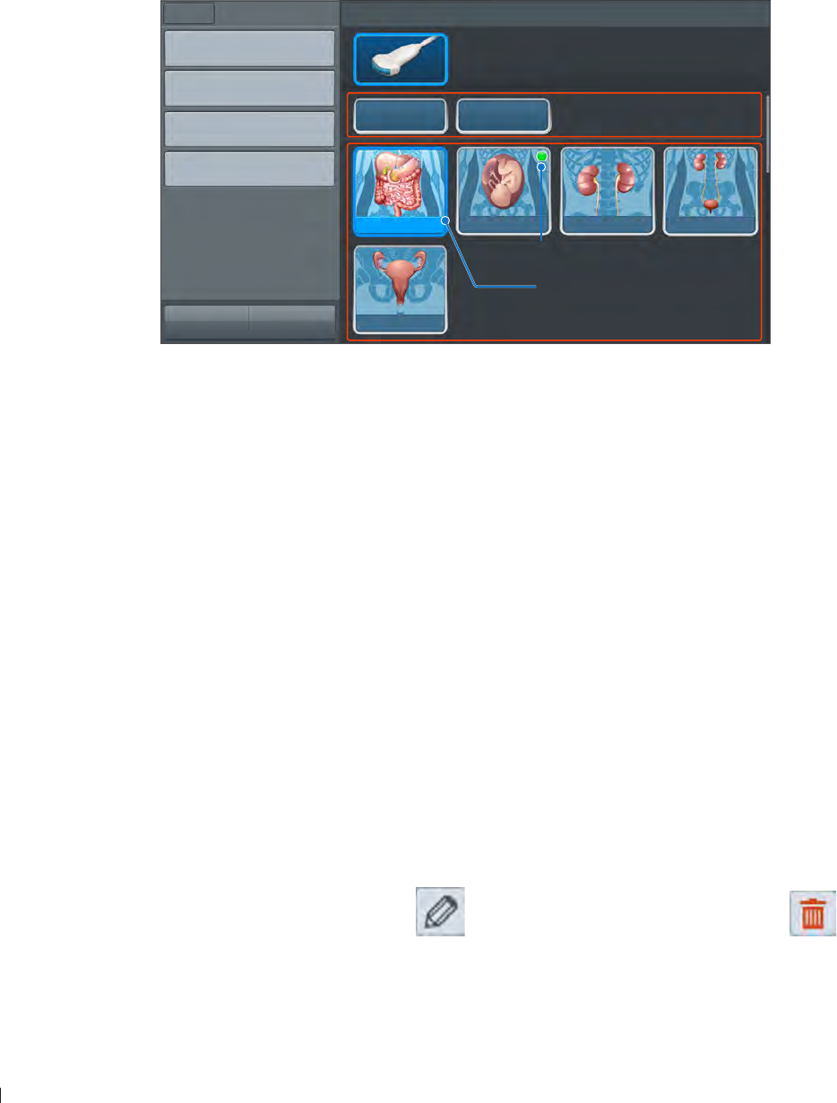
InnoSight Ultrasound System
Selecting a Preset einnx
72 P6992-4, EN, 16/12/6
Selecting a Preset
The system provides predefined presets for all supported transducers Choosing an exam loads optimized
presets for image control settings, based on the anatomy to be scanned, the transducer used, and the scan
mode The presets also specify the measurements appropriate for the exams You can directly use the
optimized presets, or adjust any of the image control settings as necessary for the specific patient and the
specific exam
1 On the imaging screen, touch Menu > Preset All the available presets compatible with the connected
transducer display on the preset screen
Create New
Management
Export
Import
Menu Preset
Home Previous
Select Preset
Custom1 Custom2
Abdomen OB Renal Urology
C6-2
GYN
Customized presets
Predefined presets
Default preset
Currently used preset
Figure 17Preset screen
2 Touch the preset to scan, and you will be redirected automatically to the real-time imaging screen
Customizing a Preset
1 On the preset screen, touch Create New
2 Enter a name for the customized (currently used) preset and touch Save
Modifying a Preset
If you have modified the parameters of an existing preset, whether default or customized, go to the preset
screen and touch Modify Current to save changes
Managing Presets
1 On the preset screen, touch Management
Touch Move, and drag to re-arrange the order of the presets
To set a frequently used preset as default, touch Set default > the desired preset
To hide an unwanted predefined preset, touch Hide & Show and touch Off on the preset
To further edit customized presets, touch on the preset to edit its name touch on the
unwanted preset to delete it
2 Touch Save to save changes
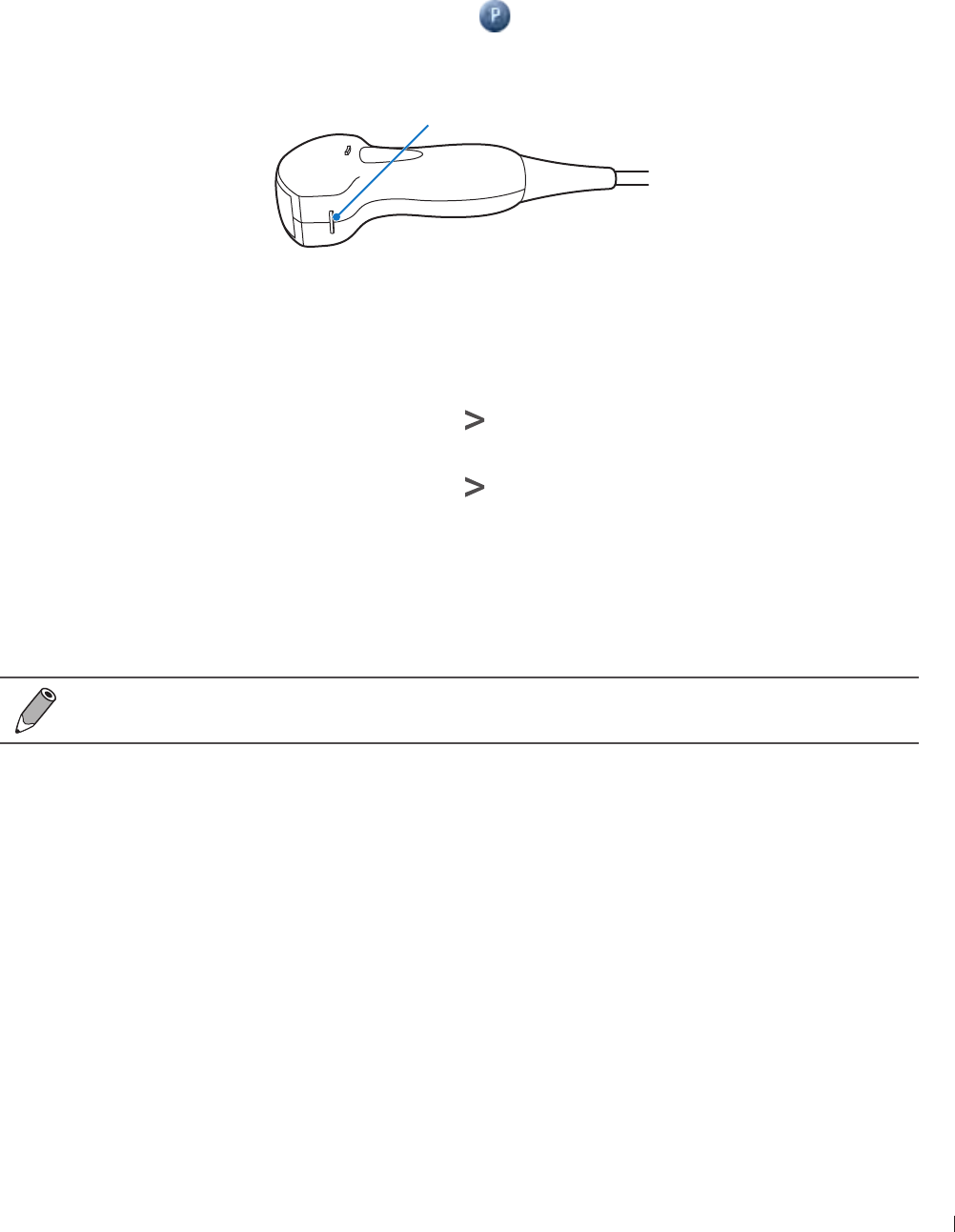
73
einnx Setting the Transducer Orientation
InnoSight Ultrasound System
P6992-4, EN, 16/12/6
Exporting and Importing Customized Presets
On the preset screen, touch Export/Import to export/import customized presets to/from your external
storage
Setting the Transducer Orientation
Upon entering all scan modes, the orientation marker ( ) displays at the default location (usually at the
top left side of the image), and suggests you the direction of holding the transducer The orientation marker
on the screen corresponds to the position of the orientation marking on the side of the transducer
Orientation marker
Figure 18Transducer orientation (Example transducer: C6-2)
You can change the left/right orientation of the image (real-time or frozen) in various imaging (single or
dual) without rotating the transducer head itself
To reverse left and right
On the imaging screen (real-time or frozen), touch > L/R
To reverse up and down
On the imaging screen (real-time or frozen), touch > U/D
Selecting/Switching a Scan Mode
On the real-time imaging screen, directly touch the scan mode buttons on the control panel to select/switch
the scan mode in use
To view a list of available scan modes, see Imaging on page 2
Adjusting the Displayed Image
On the real-time imaging screen, touch the corresponding scan mode (image control) button to select a
scan mode Use the image control settings to further optimize the image (See Chapter Using Image
Controls on page 9)
You can also perform the following operations to adjust the contents of the imaging window
Enlarging an Area of the Image
To further examine the anatomy by enlarging a region of the image (real-time or frozen), use the zoom
function
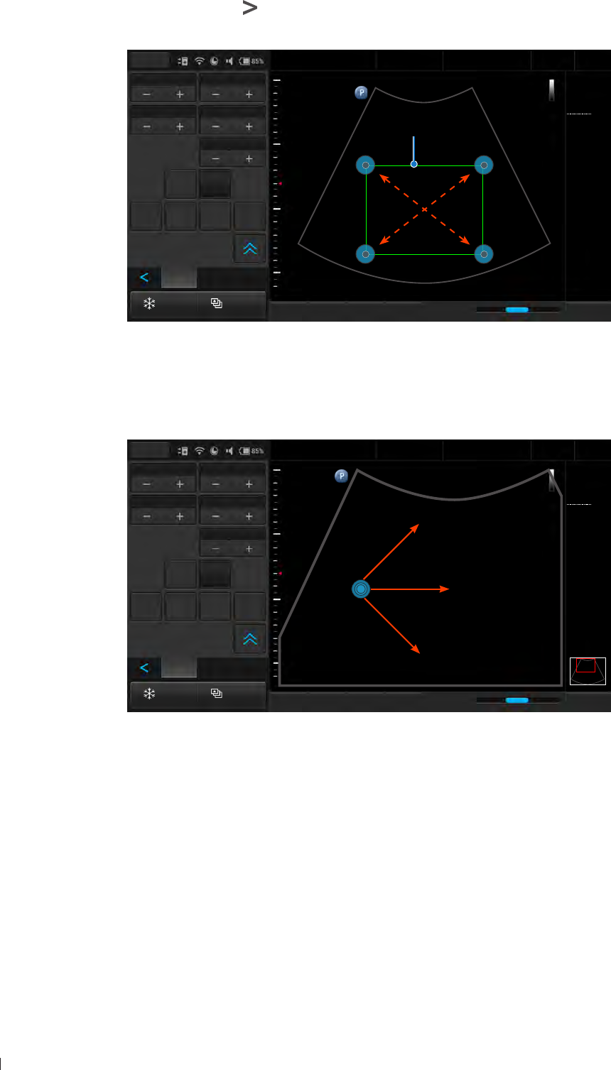
InnoSight Ultrasound System
Adjusting the Displayed Image einnx
74 P6992-4, EN, 16/12/6
1 On the imaging screen, touch > Zoom The ROI (Region of Interest) box appears on the center of the
image
Freeze Acquire
Fn Key iScan TGC Home
2D
Menu
End Exam
Pen Res
Abdomen
12/5/2016 08:56 AM
3
C6-2
MI 0.72
TIS 0.02
32 Hz
16.0 cm
2D
Gen
Gn 44
DR 78
1/ 0/ 1
3/ 0/ 6
ROI box
Depth Gain44
Sector Width256 Sector Pos
Power80.0
Body
Mark Zoom
Annot Label Arrow Erase
Annot
Figure 19Enlarge an ROI (normal image)
Touch and drag inside of the ROI box to move it to the area to enlarge Touch on any of the box’s four
corners and drag to resize the ROI box
2 Touch anywhere outside the ROI box to enlarge the selected area
Freeze Acquire
Fn Key iScan TGC Home
2D
Menu
End Exam
Pen Res
Abdomen
12/5/2016 08:56 AM
3
C6-2
MI 0.72
TIS 0.02
32 Hz
16.0 cm
2D
Gen
Gn 44
DR 78
1/ 0/ 1
3/ 0/ 6
Depth Gain44
Sector Width256 Sector Pos
Power80.0
Body
Mark Zoom
Annot Label Arrow Erase
Annot
Figure 20Enlarge an ROI (zoomed image)
3 To move the enlarged area, press and hold anywhere on the image, then drag to move it
Splitting the Imaging Screen
The system allows splitting the imaging screen into two sections to view two current scans for a patient
You can acquire one scan for the patient, enable dual screen, then acquire another scan from a different
angle, location or with a different scan mode This function is only available in 2D, 2DColor and 2DCPA
modes
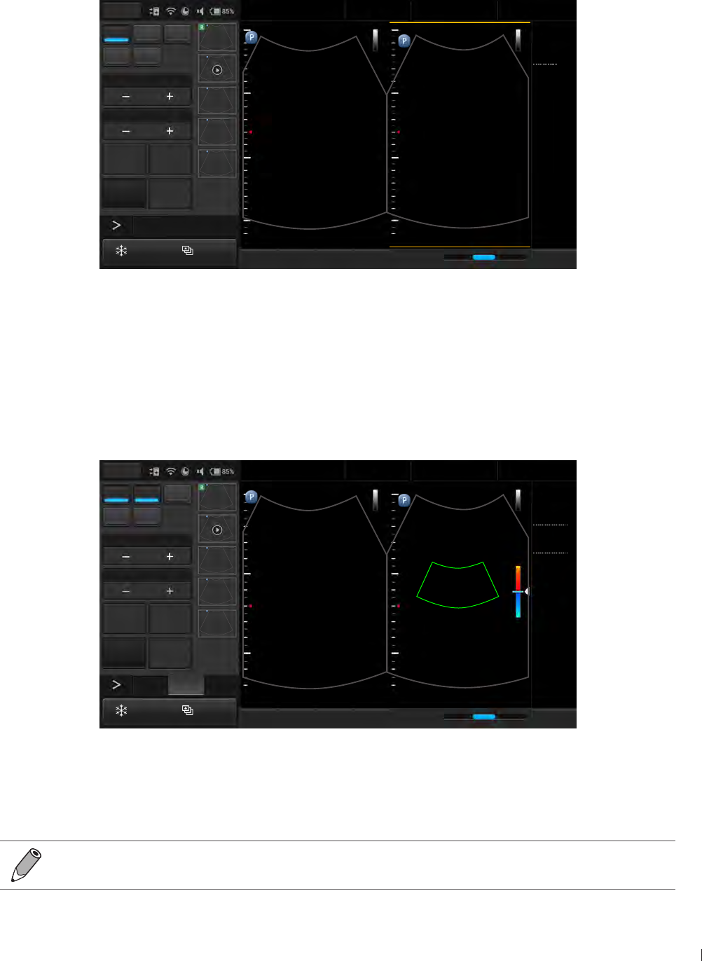
75
einnx Adjusting the Displayed Image
InnoSight Ultrasound System
P6992-4, EN, 16/12/6
When in 2D Mode:
On the imaging screen, touch Dual The system immediately freezes the current scan, and copies the
current settings for the image to the second screen Two yellow bars will be added to the top/bottom of the
currently active screen To toggle between screens, touch Toggle Only one screen can be active at a time
2D Color PW
M CPA
Focus8.0
Dyn Range78
THI Full Screen
Dual Toggle
Freeze Acquire
Fn Key iScan TGC Home
2D
Menu
End Exam
Pen Res
Abdomen
12/5/2016 08:56 AM
33
C6-2
MI 0.72
TIS 0.02
32 Hz
16.0 cm
2D
Gen
Gn 44
DR 78
1/ 0/ 1
3/ 0/ 6
5
Figure 21Dual screen: Frozen 2D mode (left) Real-time 2D mode (right) images
You can compare then apply any image control settings and use scan modes independently to either screen
For example, you can acquire a 2D scan, activate dual screen, then acquire a Color scan in the second
screen
When in 2DColor or 2DCPA Mode:
On the imaging screen, touch Dual The system copies the current settings for the image to the second
screen in 2D mode Both screens are in real-time but you get a clearer view under the ROI in 2D mode
2D Color PW
M CPA
Scale
Steer
Invert Full Screen
Dual Toggle
Freeze Acquire
Fn Key iScan TGC Home
2D Color
Menu
End Exam
Pen Res
Renal
12/5/2016 08:56 AM
C6-2
MI 0.89
TIS 0.16
13 Hz
16.0 cm
2D
Gen
Gn 44
Color
Gen
Gn 45
2/ 1/ 5
Filter 20.0Hz
33
15
-15
5
cm/s
Figure 22Dual screen: Real-time 2D mode (left) Real-time 2DColor mode (right) images
Touching Dual again freezes the 2D real-time scan and turns it into a frozen 2DColor or 2DCPA mode
image
To leave the dual screen, touch Dual
To enable dual screen when the scan is frozen, touch Compare
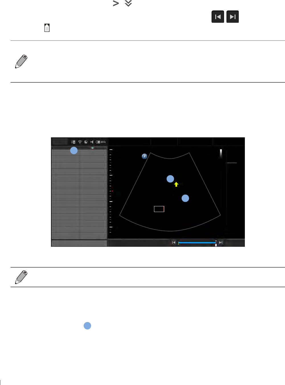
InnoSight Ultrasound System
Freezing an Image einnx
76 P6992-4, EN, 16/12/6
Freezing an Image
During a real-time scan, touch Freeze to freeze live ultrasound images recorded by frame and stored
temporarily in the cine buffer Depending on the mode selected, a certain number of frames are recorded
To play back saved images in a continuous cine loop, touch Play
To adjust the playback speed, touch > Loop Speed +/-
To view the saved images frame by frame or to find a specific frame, touch / or drag the frame
indicator horizontally
To restart a new real-time scan, touch Freeze again
If no frozen image or cine loop are saved, restarting real-time scanning erases the frame data
Make sure any needed images are saved or printed before acquiring new scan data
To change the screen to enter after you freeze the scan, on the system’s imaging screen, touch
Menu > Settings > Workflow > (Status after Freeze) > Select an option
Adding Annotations
On the frozen imaging screen, you can add annotations to the ultrasound images in order to explain the
anatomy
Left Right
Upper Lower
Medial Lateral
Anterior Posterior
SAG TRANS
PROX MID
LT Kidney RT Kidney
LT Lobe RT Lobe
Aorta Liver
CBD IVC
Duodenum Fluid
Appendix Pancreas
Gallbladder Spleen
Caudate Bowel
Close Delete Set home Go home Home
Menu
End Exam
Abdomen
12/5/2016 08:56 AM
1
1 56
C6-2
MI 0.72
TIS 0.02
32 Hz
16.0 cm
2D
Gen
Gn 44
DR 78
1/ 0/ 1
3/ 0/ 6
b
a
c
Tumor
Lower
Figure 23Add annotations
You can select whether to keep or erase the annotations added after you return to the live scan
by touching Menu > Settings > Workflow > Auto-clear Annotation after Unfreeze
Arrow
Touch Arrow An arrow appears at the text home position Drag the arrow to the desired location, and
release it to place the arrow
a
Text
1 Touch Annot A virtual keyboard and a text cursor (I-beam) appear at the text home position
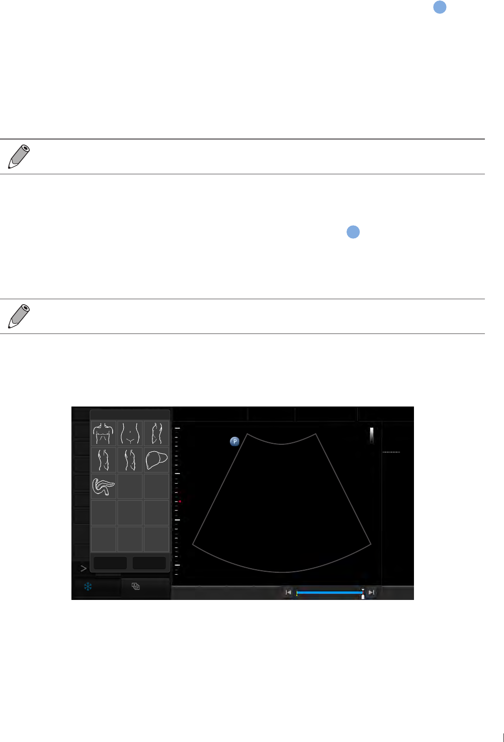
77
einnx Adding Annotations
InnoSight Ultrasound System
P6992-4, EN, 16/12/6
2 Type the texts directly Touch Done on the keyboard to finish inputs
3 Drag the text cursor to where you want the new texts to be, and release it to place the texts
b
Setting the Text Home Position
You can choose a specified position in the image display as the starting location, which is the text home
position
1 Move a set of existing texts to the desired text home position
2 Touch the texts directly, and touch Done to close the keyboard
3 Touch Set home
To restore the texts to the default text home position, simply touch the texts, close the keyboard,
then touch Go home
Label
1 Touch Label A predefined text menu appears at the control panel area
c
, and a text cursor (I-beam)
appears at the text home position
2 Select a text label to place it at the current cursor position, and touch Close
3 Drag the cursor/label to where you want the texts to be
The text labels are still editable Touch the label to display the virtual keyboard, and start editing
the texts Touch Done on the keyboard to finish editing
Body Mark
1 Touch Body Mark to display the body mark menu
Distance
Ellipse
Angle
IMT
Annot
Arrow
Report
Freeze Acquire
Fn Key Set start Set end Home
Menu
End Exam
1 56
Abdomen
12/5/2016 08:56 AM
1
C6-2
MI 0.72
TIS 0.03
33 Hz
16.0 cm
2D
Gen
Gn 43
DR 78
1/ 0/ 1
3/ 0/ 6
Body Mark (7)
Close Erase
Figure 24Add a body mark
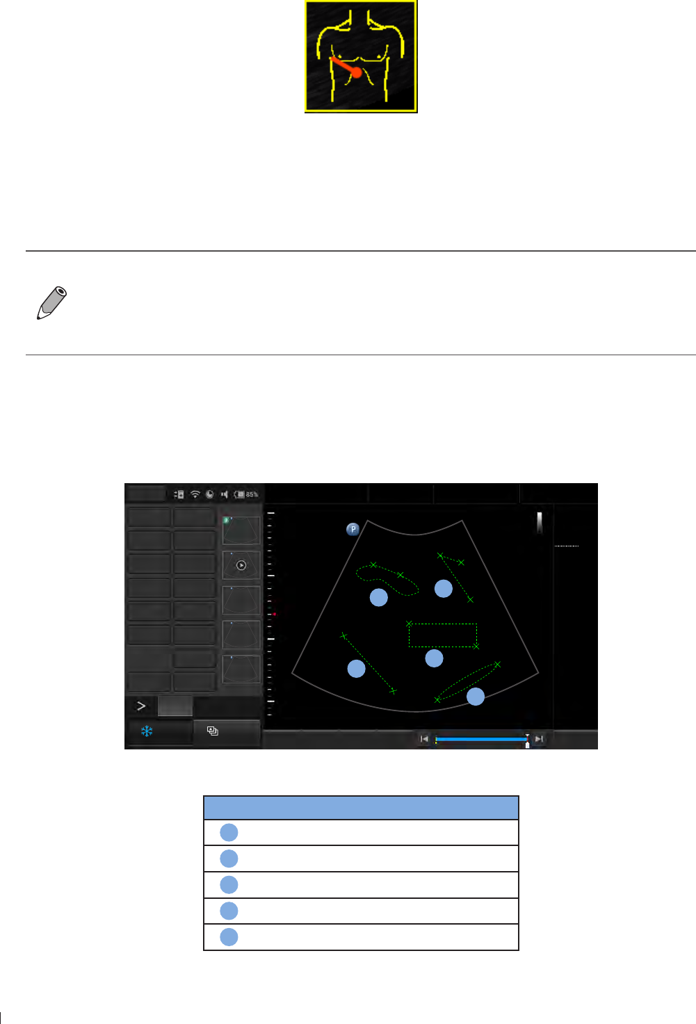
InnoSight Ultrasound System
Adding Measurements einnx
P6992-4, EN, 16/12/6
2 Select a body mark A pictogram of the body mark with a transducer indicator displays on the image
Figure 25Pictogram of the body mark (example)
3 Touch anywhere on the image, and drag the transducer indicator to the desired location on the body
mark
4 Touch anywhere on the image and move to rotate the transducer indicator
Touch and hold the pictogram, and drag it to the desired location on the image
To delete annotations, including texts and arrows, touch Erase Annot to erase the last
annotation added Repeat this action, if needed, to continue erasing annotations
To directly erase all annotations, touch and hold Erase Annot
To delete the body mark added, touch Body Mark > Erase
To set whether to show all or the last annotations, or to hide them all, touch Show Annot +/-
Adding Measurements
Measurements accompanying ultrasound images supplement other clinical procedures available to the
attending physician You can perform as many measurements as needed
1
Distance Depth
Ellipse Trace
Angle Calc
IMT Erase Meas
Annot Label
Arrow Body Mark
Erase Annot
Report Play
5
Freeze Acquire
Fn Key Set start Set end Home
Menu
End Exam
1 56
Abdomen
12/5/2016 08:56 AM
2D
1 Distance 87.5 mm
2 Ellipse
EA 119.8 mm2
EP 122.6 mm
Ea 61.2 mm
Eb 2.5 mm
3 Trace
TA 21.05 cm2
TB 2.78 cm
4 Angle 36.54
5 IMT
Max 1.02 mm
Min 0.81 mm
Avg 0.95 mm
Std 0.06 mm
C6-2
MI 0.72
TIS 0.03
76 Hz
16.0 cm
2D
Gen
Gn 54
DR 78
1/ 0/ 1
1/ 0/ 4
a
1
b
2
3
c
5
e
4
d
Figure 26Perform measurements
Item Measurement type Reference page
a
Distance (See page 9)
b
Ellipse (See page 9)
e
Trace (See page 9)
d
Angle (See page )
e
IMT (See page )
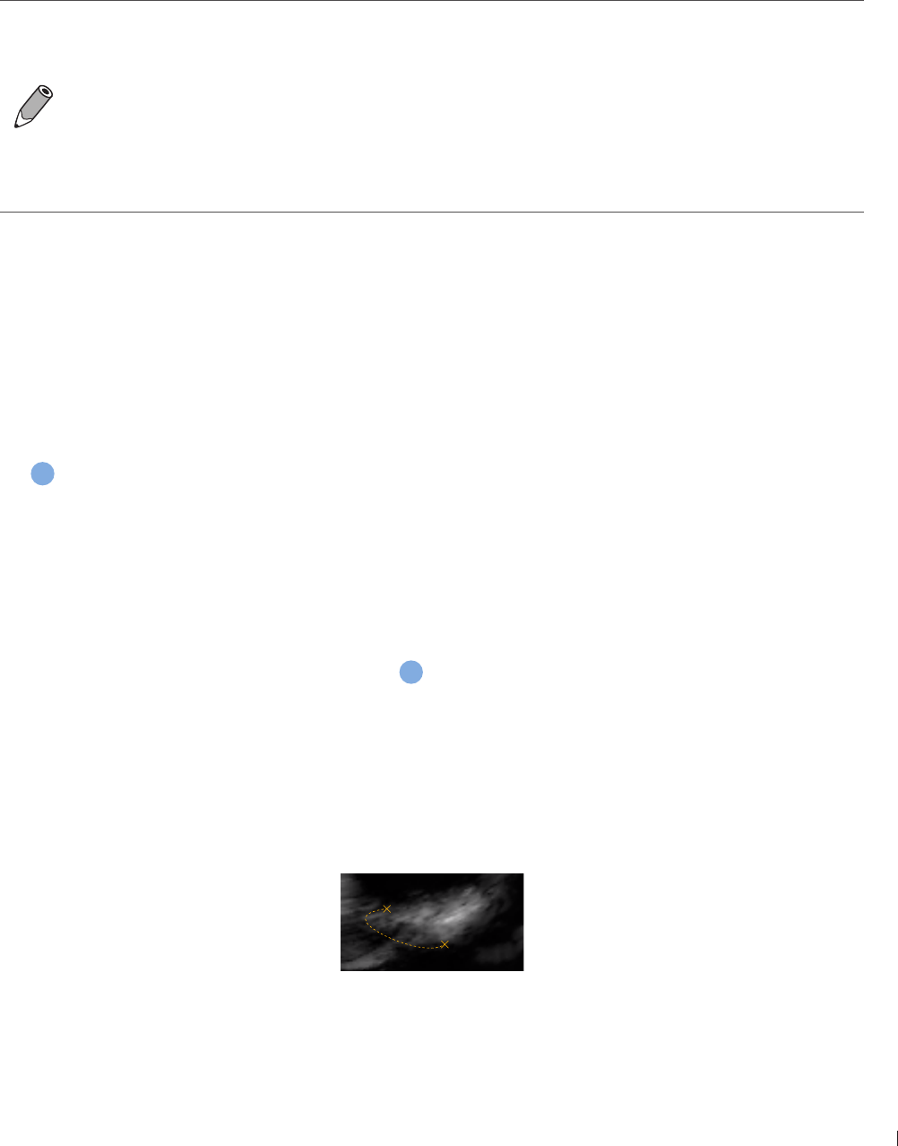
79
einnx Adding Measurements
InnoSight Ultrasound System
P6992-4, EN, 16/12/6
When you are measuring, the indicators/lines display in yellow, allowing you to adjust as many times
as needed When you are done with measuring, use any of the following methods to complete the
measurement The indicators/lines then turns green, and the measured results (values) appear on the top
left side of the imaging screen
Two-finger tap on the scan area
Proceed with the next measurement
Touch Acquire to save the ultrasound image
To re-position the measured results, touch Result Pos +/-
To set whether to show all or the last measured results, or to hide them all, touch Show Result
+/-
To delete measurements, touch Erase Meas to erase the last measurement added Repeat this
action, if needed, to continue erasing measurements
To directly erase all measurements, touch and hold Erase Meas
You can select whether to keep or erase the measurements added after you return to the live
scan by touching Menu > Settings > Workflow > Auto-clear Measurement after Unfreeze
Measuring in 2D/Color/CPA Modes
Distance
Measure a distance
1 Touch Distance A crosshair cursor appears on the image Drag the target cursor to where you want to
start measuring and release it
2 Drag the target cursor to where you want to finish measuring, then release it to complete measurement
a
Ellipse
Measure a circumference
1 Touch Ellipse A crosshair cursor appears on the image Drag the target cursor to one end of the area
you want to measure and release it to set the start point of measurement
2 Drag the target cursor to the other end of the desired area, and release it to set the end point of
measurement An oval area is then measured
b
Trace
Manually trace an irregular shape
1 Touch Trace A crosshair cursor appears on the image Drag the cursor to where you want to start
measuring and release it
2 Drag the cursor along the outline of the object to trace
Figure 28Trace an outline

InnoSight Ultrasound System
Adding Measurements einnx
P6992-4, EN, 16/12/6
3 When the tracing is nearly done, release the cursor and the system completes the loop by drawing a
line from the current cursor position to the starting point
c
Angle
Measure an angle
1 Touch Angle A crosshair cursor appears on the image Drag the target cursor to the desired location
and release it to set the start point of measurement
2 Drag the first target cursor along one side of the desired area, and release it to draw the first line
3 Drag the second target cursor along the other side of the area, and release it to draw the second line
The angle between the two lines is then formed
d
IMT
Measure IMT (Intimal Media Thickness) of the carotid artery, which is useful for detecting early signs of
arteriosclerosis
1 Touch IMT A crosshair cursor appears on the image Drag the target cursor to the desired location and
release it to set the start point of measurement
2 Drag the target cursor to the other end of the desired area, and release it to set the end point of
measurement
e
Calculation Package
Perform a set of predefined measurements based on the scan mode/calculation method you select
1 Touch Calc to open the calculation package menu
2 Touch a desired calculation method The items to measure display in a list of order under the selected
method
3 Touch the first item and the screen displays the corresponding cursor Drag it to perform measurement
4 After you have finished with the measurement, touch the second item The first item is checked
automatically with the measured result
Repeat step 3-4 to perform the rest of the measurements on the list
For measurement accuracy and precision in 2D measurement:
Linear distance measurement errors will be less than
Perimeter, and ellipse circumference measurement errors will be less than
Area measurement errors are related to the linear distance measurement and will be less than
1
Measuring in M-Mode
Distance
Measure the length between two horizontal lines that lean on two cursors The position of the vertical time
lines does not affect the distance measurement
1 Touch Distance A crosshair cursor with horizontal and vertical axes appears on the time series window
Drag the cursor to a desired start point on the vertical axis and release it
2 A second cursor appears Drag it to the end point on the vertical axis then release it to complete
measurement

1
einnx Adding Measurements
InnoSight Ultrasound System
P6992-4, EN, 16/12/6
Slope
Measure the length between the intersections of two cursors Slope can be positive or negative and
measures the rate of change between the two points defined by the intersections of the cursors in cm/sec
1 Touch Slope A crosshair cursor with horizontal and vertical axes appears on the time series window
Drag the cursor to a desired start point and release it
2 A second cursor appears Drag it to the end point then release it to complete measurement
The slope measurement is not restricted to either the horizontal or the vertical axis of the start
marker
Time
Measure the length between two vertical time lines created by two cursors The position of the horizontal
distance lines does not affect time measurements
1 Touch Time A crosshair cursor with horizontal and vertical axes appears on the time series window
Drag the cursor to a desired start point on the horizontal axis and release it
2 A second cursor appears Drag it to the end point on the horizontal axis then release it to complete
measurement
Heart Rate
Measure the length between two vertical lines created by two cursors in beat per minute (BPM) The
position of the horizontal distance lines does not affect the heart rate
1 Touch Heart Rate A crosshair cursor with horizontal and vertical axes appears on the time series
window Drag the cursor to a desired start point on the horizontal axis and release it
2 A second cursor appears Drag it to the end point on the horizontal axis then release it to complete
measurement
Measuring in Spectral Doppler Mode
Auto Trace
Trace the spectrum of Doppler waveforms
Touch High Q The trace for the Doppler spectrum will be performed automatically with measurements
calculated and displayed on the screen
Semi-Trace
Trace the Doppler spectrum with better accuracy in the measurement calculation
1 Touch Semi Trace A crosshair cursor with vertical axis appears on the time series window Drag the
cursor to a desired peak of the graph and release it
2 A second cursor appears Drag it to end diastole on the graph then release it
3 A third cursor appears Drag it to the second peak of the graph and release it
4 Touch anywhere on the screen to complete the trace
To obtain an accurate auto-trace and measurement result, a quality Spectral Doppler image with
clean noise background is required
InnoSight Ultrasound System
Saving and Printing the Image einnx
2 P6992-4, EN, 16/12/6
Trace
Manually trace the Doppler spectrum
1 Touch Semi Trace A crosshair cursor with vertical axis appears on the time series window Drag the
cursor to a desired peak of the graph and release it
2 A second cursor appears Drag it to end diastole on the graph then release it
3 A third cursor appears Drag it to the second peak of the graph and release it to complete the trace
Velocity
Measure the blood flow velocity
Display item Contents (units)
VFlow Velocity (mm/s)
PG Pressure gradient (mmHg)
Touch Velocity A crosshair cursor with vertical axis appears on the time series window Drag the cursor to
the measurement point, and release your finger to place it
General Measurement
Used to perform a set of basic Spectral Doppler measurements including peak systolic velocity, velocity
time integral, end diastolic velocity, pressure gradient and acceleration time
Display item Contents (units)
V1 Peak systolic velocity (mm/s)
V2 End diastole velocity (mm/s)
P1/P2 Pressure gradient (mmHg)
Accl Acceleration time (mm/s2)
Time Time (s)
1 Touch 2-Points A crosshair cursor with vertical axis appears on the time series window Drag the cursor
to a desired peak of the graph and release it
2 A second cursor appears Drag it to end diastole on the graph and release it The measured results
(values) appear on the screen
For measurement accuracy and precision in PW Doppler measurement:
Velocity measurement will be less than 12
The measured results of performing Trace, Semi-Trace and Auto Trace vary depending on the
transducer connected
Saving and Printing the Image
After adding annotations/measurements to the image, you can save or print the image
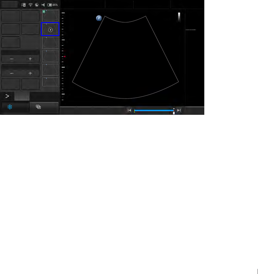
3
einnx Reviewing the Image
InnoSight Ultrasound System
P6992-4, EN, 16/12/6
Saving an Image Loop
On the real-time imaging screen, touch Acquire to save a default set of frames as an image loop The saved
image loop will be displayed in the thumbnail list
Saving an Image
On the frozen imaging screen, touch Acquire to save the current frame as an image The saved image will
be displayed in the thumbnail list
Printing an Image
On the frozen imaging screen, touch Print to print out the current image
Reviewing the Image
On the frozen imaging screen, flick vertically on the thumbnail list to view the thumbnails of all the saved
images/loops
To further examine one or a set of images/loops, touch the thumbnail of the desired image or image loop
to display the review screen
Add to
Report Report
Export exam Delete
Play
Multi-Select1*1
Multi-Compare1*1
Print Exam List
2/11
Fn Key Set Start Set End Home
Menu
End Exam
Abdomen
12/5/2016 08:56 AM
C6-2
MI 0.72
TIS 0.02
32 Hz
16.0 cm
2D
Gen
Gn 44
DR 78
1/ 0/ 1
3/ 0/ 6
3
2D
1 56
Figure 29Review the image
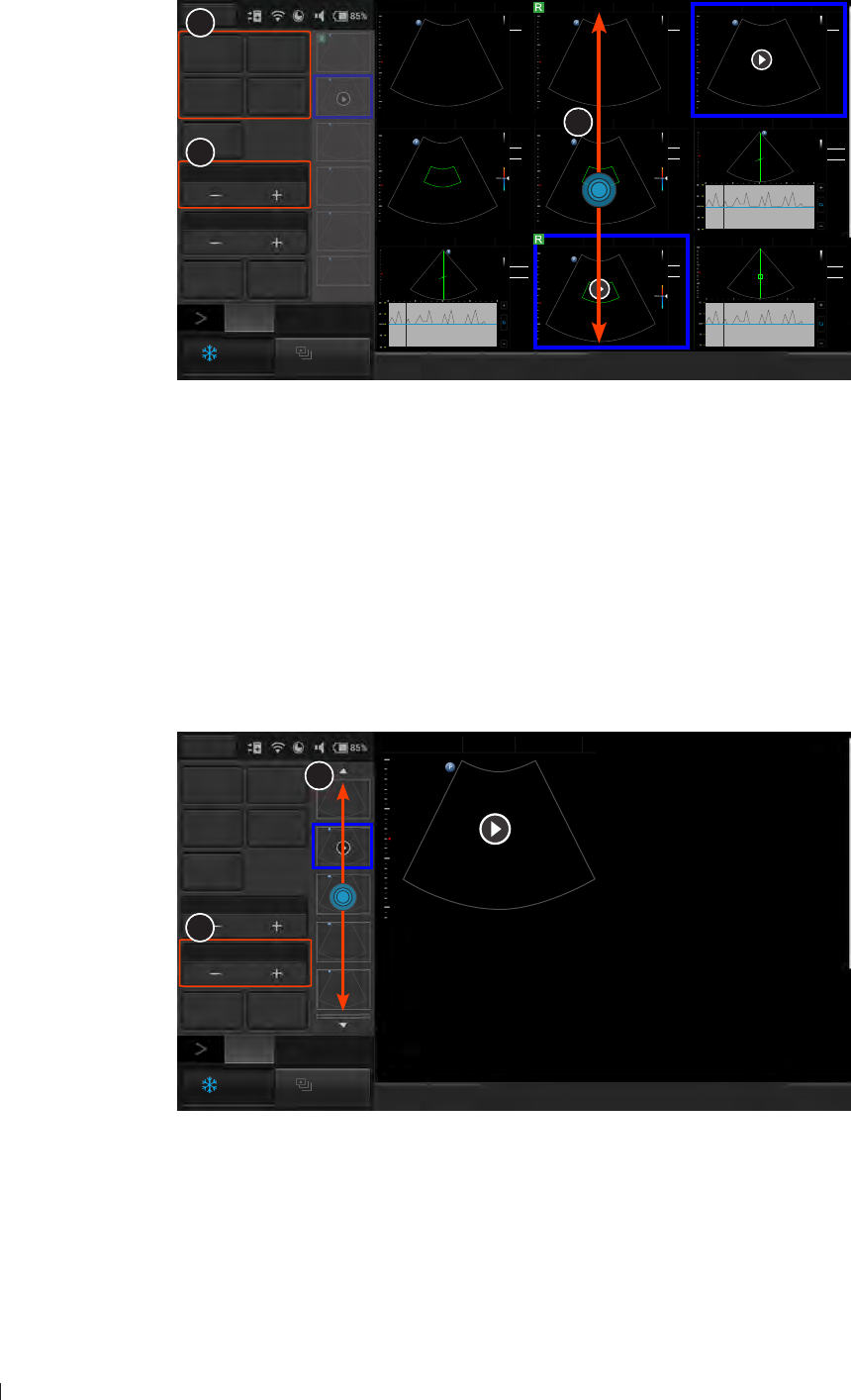
InnoSight Ultrasound System
Reviewing the Image einnx
4 P6992-4, EN, 16/12/6
Performing Multiple Selections
You can perform actions to more than one image/loop at a time
Fn Key Select All Deselect All Home
Menu
End Exam
Add to
Report Report
Export exam Delete
Play
3*3
1*1
Print Exam List
2D
Abdomen
12/5/2016 08:56 AM
C6-2
MI 0.72
TIS 0.03
18 Hz
16.0 cm
2D
Gen
Gn 39
DR 80
1/ 0/ 1
1/ 0/ 4
1
Cardiac
12/5/2016 08:56 AM
S4-2
MI 1.31
TIS 1.09
76 Hz
14.0 cm
2D
Gen
Gn 44
PW
Gen
Gn 50
Angle 60
6.91 cm
Filter 280.0Hz
1
Update
Abdomen
12/5/2016 08:56 AM
1
C6-2
MI 0.72
TIS 0.03
18 Hz
16.0 cm
2D
Gen
Gn 39
DR 80
1/ 0/ 1
1/ 0/ 4
Abdomen
12/5/2016 08:56 AM
1
C6-2
MI 0.72
TIS 0.03
18 Hz
16.0 cm
2D
Gen
Gn 39
DR 80
1/ 0/ 1
1/ 0/ 4
Renal
12/5/2016 08:56 AM
1
15
-15
C6-2
MI 1.04
TIS 0.34
12 Hz
12.0 cm
2D
Gen
Gn 41
Color
Gen
Gn 47
1/ 1/ 5
Filter
20.0Hz
Liver
12/5/2016 08:56 AM
1
15
-15
C6-2
MI 1.04
TIS 0.34
12 Hz
12.0 cm
2D
Gen
Gn 41
Color
Gen
Gn 47
1/ 1/ 5
Filter
20.0Hz
Abdomen
12/5/2016 08:56 AM
1
15
-15
C6-2
MI 1.04
TIS 0.34
12 Hz
12.0 cm
2D
Gen
Gn 41
Color
Gen
Gn 47
1/ 1/ 5
Filter
20.0Hz
Cardiac
12/5/2016 08:56 AM
1
Update
S4-2
MI 1.31
TIS 1.09
76 Hz
14.0 cm
2D
Gen
Gn 44
PW
Gen
Gn 50
Angle 60
6.91 cm
Filter 280.0Hz
Cardiac
12/5/2016 08:56 AM
1
Update
S4-2
MI 1.03
TIS 3.14
76 Hz
14.0 cm
2D
Gen
Gn 44
CW
Gen
Gn 50
Angle 0
7.0 cm
Filter 80.0Hz
2
1
3
2/11
Figure 30Perform multiple selections
1 Touch Multi-Select +
2 Flick vertically on the thumbnail window and touch to select up to 9 images/loops
To quickly select all images, touch Select All
To cancel all selections, touch Deselect All
3 Touch an action button For example, touch Delete to delete all selected images/loops
Comparing Images
You can compare the scanned images/loops by displaying selected ones on the screen
Add to
Report Gen Report
Export exam Delete
Play
1*1
2*2
Print Exam List
Please press thumbnail to add to review list
Fn Key Home
Menu
End Exam
Abdomen
12/5/2016 08:56 AM
Please press thumbnail to add to review list
11
Please press thumbnail to add to review list
2D
2
1
Figure 31Compare images
1 Touch the Multi-Compare +
2 Flick vertically on the thumbnail list, and touch to select up to 4 images/loops to display for comparison
3 Touch an action button
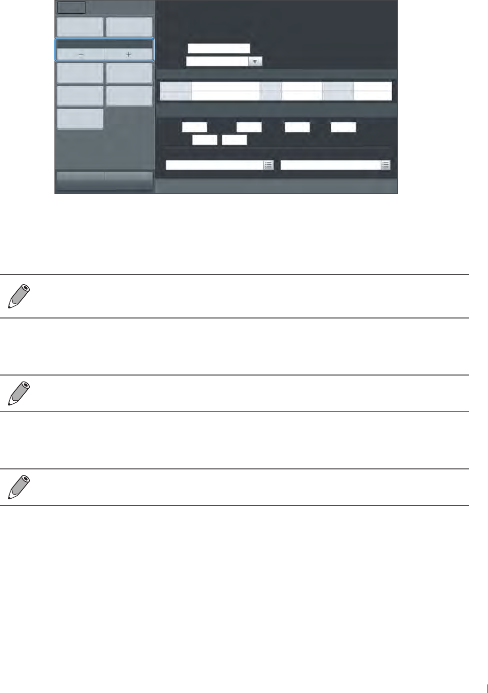
einnx Exporting the Exam
InnoSight Ultrasound System
P6992-4, EN, 16/12/6
Generating a Report
1 On the review screen, touch the thumbnails of the desired images and touch Add to Report
2 Touch Gen Report to display the following screen
Study date: 2015/09/03Liver
Institution:
Referring:
Interpreting:
Signature:
Template Cardiac
Patient information
Last Name M.I. First Name
ID DOB Age
Print Print Preview
1 column
Add Image Delete Image
Exam List Export
One Page Report
Menu Report
Home Previous End Exam
Study Specific Information
Height cm Weight kg BSA: M2HR bpm
Blood Press / mmHg
Prompts Findings
Figure 32Report screen
3 Fill in information about the patient and the study, if not complete, and add comments using the virtual
keyboard
4 Flick down to review the images added, and add comments to individual images, if needed
You can still add/remove images to/from the report without going back to the review screen
Touch Add Image to display the image editing screen Check/uncheck the desired images and
touch Add to Report
Touch Image Layout + to select the numbers of columns for placing the images on a report
6 To save the report, touch Export, select the file format and directory, enter the file name then touch
Save as file
To save the report, an external storage device must be connected to the system
To print out the entire report with scanned images, first touch Print Preview to preview the report,
then touch Print
To print out the report in texts only, touch One Page Report > Print
On the print review screen, you can choose different ways to preview the report
Exporting the Exam
You can export exams and images to an external storage or the DICOM server When exporting an exam, an
image or a cine loop, the system creates a uniquely named subdirectory for each exam, image or loop
1 The system provides three ways of exporting the exam:
On the review screen, touch Export exam
On the Exam List screen, check the completed exams, and touch Export Exam
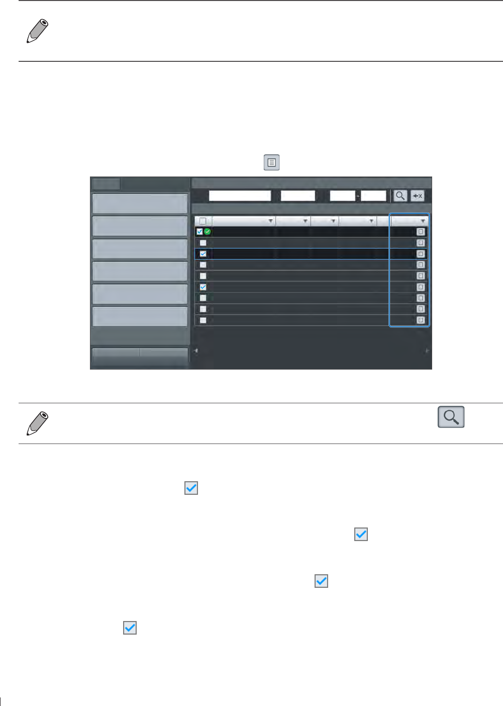
InnoSight Ultrasound System
Managing the Exam List einnx
6 P6992-4, EN, 16/12/6
On the report screen, touch Export
2 Touch Export exam to DICOM, Export exam to external storage or Export media image to external
storage
To set the default export directory, export to DICOM automatically after ending the exam and
more, touch Menu > Settings
For more information on configuring DICOM settings, see DICOM Configuration on
page 66
Managing the Exam List
You can check and update status of all the stored exams from the Exam list screen
On the imaging screen, touch Menu > Exam List Refer to the Status column to check the status of each
exam To review images/video clips of an exam, touch
Name ID Type Study date Image Status
New Exam
Continue
Complete
Delete Exam
Export Exam
Import
Menu Exam List
Home Previous
Search Exam
Name ID Date
Exam List
Exam Image & Clip
Complete
Pause
Processing
Figure 33Exam list screen
Alternatively, you can enter the query in any of the Name/ID/Date fields, and touch to start
the query Patients matching the query will be listed on the screen
Resuming an Exam
To resume an exam, check the exam and touch Continue to enter real-time scanning
Starting a New Exam
To start a new exam from a patient with an existing exam, check the exam and touch New Exam
Finishing Exams
To update the exam status as Complete, multi-check the exams and touch Complete
Deleting Exams
Multi-check the exams and touch Delete to delete exams

einnx Ending the Exam
InnoSight Ultrasound System
P6992-4, EN, 16/12/6
Exporting Exams
To export exams, multi-check the exams , touch Export Exam and select an export method The task
status icon (See page 6) next to the checkbox indicates the uploaded result of the exam
Importing Exams
Multi-check the exams and touch Import from an external storage
Ending the Exam
An exam is not complete if you proceed with a new exam without ending the previous one
To end the exam, touch End Exam on the imaging screen
To check the exam status, go to Menu > Exam List

InnoSight Ultrasound System
P6992-4, EN, 16/12/6
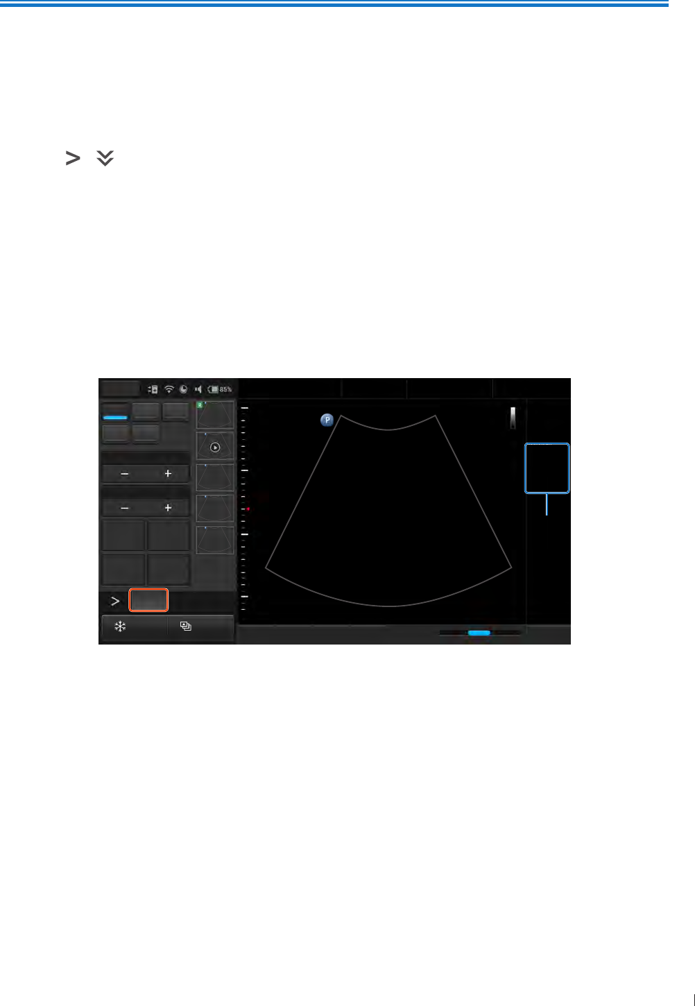
89
inen 2D Mode Image Controls
7
P6992-4, EN, 16/12/6
7 Using Image Controls
All of the information in this chapter pertains to real-time imaging Many of the controls and functions
change when you freeze the scan For information on using functions when the scan is frozen, see Adding
Annotations on page 6 and Adding Measurements on page
On the real-time imaging window:
Touch the scan mode (image control) buttons to select the scan mode (See Imaging Screen (Real-time)
on page )
Touch > to switch the control panel pages to go through the available functions (See Switching
the Control Panel Pages on page 62)
2D Mode Image Controls
Overview
The system delivers 2-dimensional digital imaging using 26-level gray map This scan mode delivers
excellent image uniformity, tissue contrast resolution, and steering flexibility in frequencies from 2 MHz to
1 MHz
TGC
2D PW
M
8.0
78
THI
Zoom
5
2D
C6-2
2D
1
Figure 342D mode real-time scan
Adjusting Gain
Adjust amplification of the returning echoes, which adjusts the amount of echo information displayed in an
image The overall brightness of the image can be elevated, but the noise may also be added to the image
with excessive increase in gain
Touch Gain +/- or flick horizontally on the scan area to adjust the gain value
Adjusting Frequency
Change the scan frequency to obtain higher resolution as frequency increases, or deeper penetration as
frequency decreases
To increase the frequency, touch Res To decrease the frequency, touch Pen

InnoSight Ultrasound System
2D Mode Image Controls inen
9 P6992-4, EN, 16/12/6
Adjusting Time Gain Compensation (TGC)
Adjust the gain which compensates for the attenuation (a reduction in sound amplitude) of the echo signals
in proportion to their depth (based on travel time)
Touch TGC to display the TGC sliders on the screen To increase/decrease the gain at the desired section
(depth) of the image, drag the corresponding slider to the right/left
Adjusting the Scan Depth
Adjust the field of view To view larger or deeper structures, increase the depth To enlarge the display of
structures near the skin line, decrease the depth The system automatically adjusts the frame rate (FPS) and
acoustic power indices (TI/MI) based on the scan depth
Touch Depth +/- or flick horizontally on the scan area to set the scan depth
Adjusting the Focus Depth, Focal Zone and Focal span
Focus optimizes the image by increasing the resolution for a specific area and is displayed by a red arrow
marker indicated at the depth ruler Depending on the transducer in use and the mode selected, multiple
focus depths can be added Increasing the number of focal zones decreases the frame rate If the frame
rate is not high enough, try decreasing the number of focal zones
Touch Focus +/- to adjust the depth value Touch Focal Zone +/- to select the desired number of focal
zones Touch Focal Span +/- to adjust the distance between the focal zones
Adjusting Dynamic Range
Control the range of acoustic levels displayed in the image, which affects the contrast of the image
Touch Dyn Range +/- to adjust the amount of compression
Using Tissue Harmonic Imaging (THI)
Reduce superficial artifact and provide better gray scale contract by processing an integer multiple of the
fundamental frequency, a harmonic wave
Touch THI to enable this function
Adjusting Persistence
Adjust the amount of frame averaging from real-time images or loops Higher persistence produces less
speckled and smoother image but reduces the temporal resolution
Touch Persist +/- to adjust the value
Adjusting Sharpness and Smoothing
Improve the sharpness of the image by enhancing the edge contrast and smoothening the tissue speckle
Touch XRES +/- to adjust the value
Adjusting Gray Map
Change how the amplitude is converted to brightness
Touch Gray Map +/- to adjust the value

91
inen 2D Mode Image Controls
InnoSight Ultrasound System
P6992-4, EN, 16/12/6
Adjusting Chroma Map
Adjust the chroma (color tone and saturation) value with different brightness
Touch Chroma +/- to adjust the tone
Adjusting Steer Angle
Optimize the viewing area by adjusting the steer angle This function works only with linear array
transducers
Touch Steer +/- to adjust the angle
Adjusting the Sector Width and Position
Adjust the ROI of the imaging area for image width and image position A smaller sector width increases the
frame rate
Touch Sector Width +/- to adjust the width Touch Sector Pos +/- to adjust the position
Adjusting Power
Adjust the acoustic output power value to the expected target
Touch Power +/- to adjust the value
Using Trapezoidal Imaging
Increase the range of view of the ultrasound image when using a linear transducer
Touch Trap to enable trapezoidal imaging
Adjusting Density
Adjust the density of the scan lines Higher density obtains better horizontal resolution with lower frame
rate, while lower density obtains higher frame rate
Touch Density repeatedly to select a desired line density
Using Compound Imaging
Reduce speckles and improve contrast resolution
Frequency compounding: Combine multiple images acquired from different frequencies Touch FQBeam
to enable frequency compounding
Spatial compounding: Combine multiple images acquired from different beam angles Touch SonoCT
repeatedly to enable and adjust spatial compounding
Using ENV (Enhanced Needle Visualization)
When performing a biopsy with the supported transducer, the system offers on-screen needle guides to
further enhance imaging of the needle Before using the ENV function, make sure the following conditions
are met:
2D mode is selected
An L12-4 transducer is connected to the system
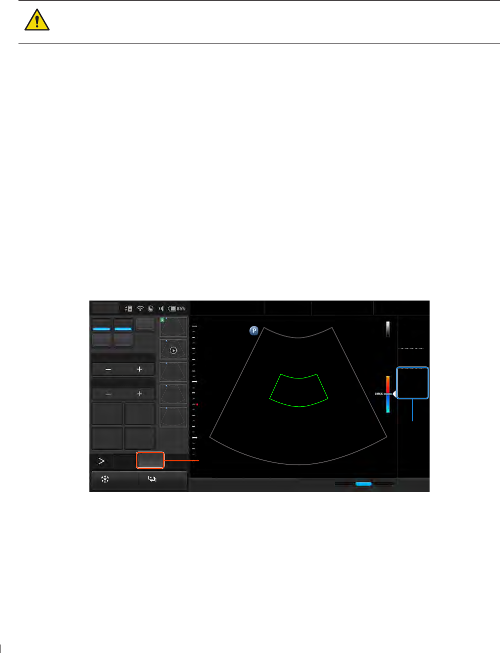
InnoSight Ultrasound System
Color/CPA Mode Image Controls inen
92 P6992-4, EN, 16/12/6
A patient profile is selected
Touch ENV to enable this function
A diverging dotted green line show in the Imaging window The point of the needle should be close to
vertical to the dotted line The part of the needle image that goes beyond the limit will not be brightened
and can’t be seen Tap ENV Angle repeatedly, if needed, to toggle between lines angled from upper left to
lower right and lines angled from upper right to lower left
The system does not support the biopsy guide function Do not use nor assemble any kind of
needle guide kits/brackets on the transducer supported to avoid transducer damage or hurting
the patient
Color/CPA Mode Image Controls
Overview
Color mode is used to detect the presence, direction, and relative velocity of blood flow by assigning color-
coded information to these parameters The color is depicted in a region of interest (ROI) that is overlaid on
the 2D image Non-inverted flow towards the transducer is assigned shades of red, and flow away from the
transducer displays in shades of blue
All forms of ultrasound-based imaging of red blood cells are derived from the received echo of the
transmitted signal The primary characteristics of this echo signal are its frequency and its amplitude (or
power) The frequency shift is determined by the movement of the red blood cells relative to the transducer
flow towards the transducer produces a higher-frequency signal and flow away from the transducer
produces a lower-frequency signal Amplitude depends on the amount of moving blood within the volume
sampled by the ultrasound beam Large frequency shift generated by rapid flow is displayed in lighter
colors, and smaller frequency shift in darker colors
2D PW
M
TGC
2D
C6-2
2D
1
15
-15
5
Figure 35Color mode real-time scan
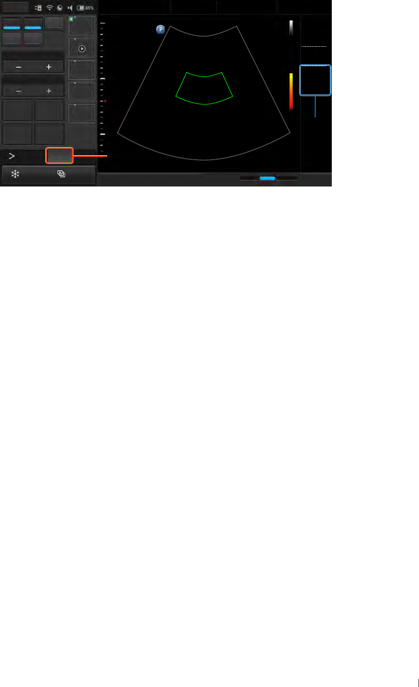
93
inen Color/CPA Mode Image Controls
InnoSight Ultrasound System
P6992-4, EN, 16/12/6
In CPA (Color Power Angio) mode, low flow rate in small vessels are clearly observed Colors are carried
out only to demonstrate the blood flow, but contain no velocity information, thus, offer no directional
information
2D PW
M
TGC
2D
C6-2
2D
1
5
Figure 36CPA mode real-time scan
Both Color and CPA modes can work with other scan modes to form duplex and triplex modes
Adjusting Pulse Repetition Frequency (PRF)
Adjust the velocity range of the color flow display The maximum velocity range depends on the transducer
in use and the location of the sample volume Set the PRF high enough to prevent aliasing, and low enough
to provide adequate detection of slow blood flow Upon adjusting the PRF value, the velocity scale shown
on the Color/CPA wedge and the Wall Filter setting are changed accordingly
Touch Scale +/- to adjust the value
Adjusting Wall Filter (WF)
Reduce or eliminate unwanted low-frequency, high-intensity signals generated by movements of blood
vessel walls or by rapid movement of the transducer Set the wall filter high enough to ensure that the
Color Doppler flash artifacts from tissue or wall motion are not displayed, but low enough to display slow
flow The adjustable range of the Wall Filter value is related to the current PRF value
Touch Wall Filter +/- to adjust the value
Applying the Smoothing Filter
Reduce color noise by applying a smoothing filter to the image
Touch Smoothing +/- to adjust the value
Adjusting the Color Priority
Define the amount of color displayed over bright echoes, and help confine color within the vessel walls
Touch Priority +/- to adjust the value
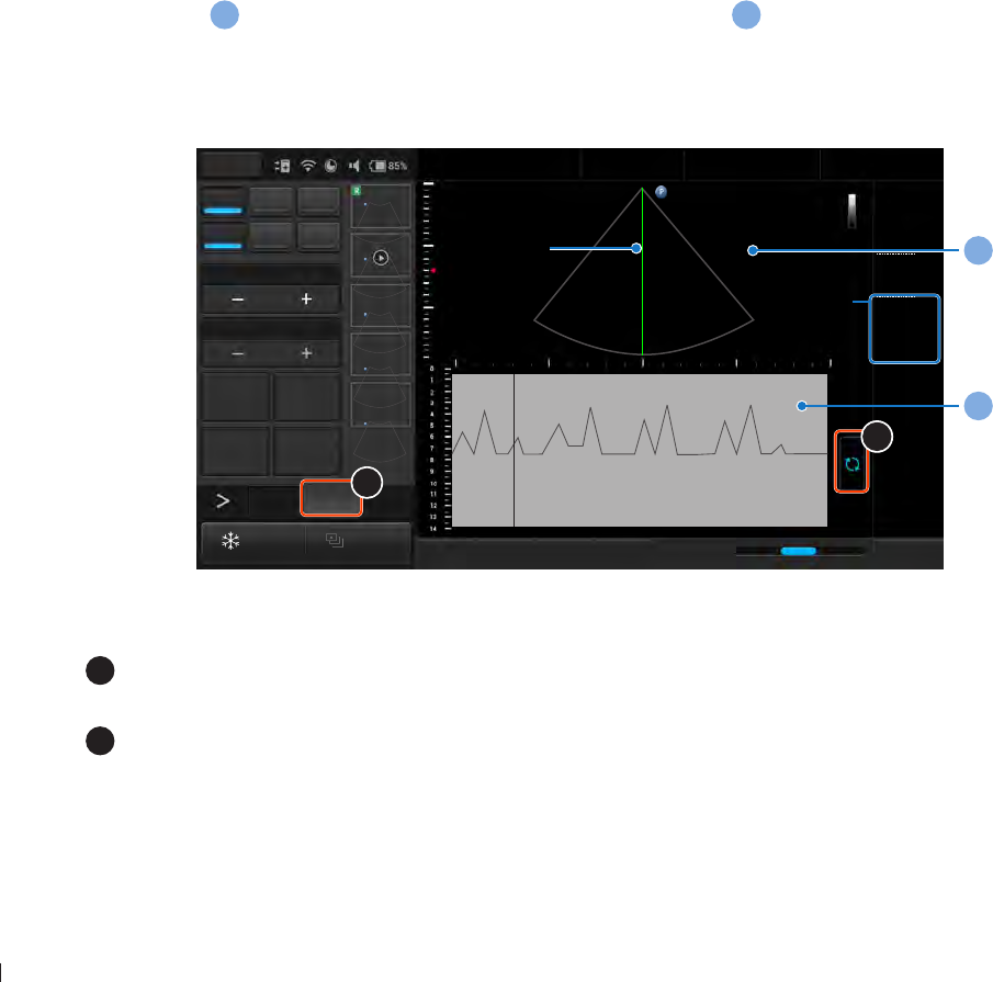
InnoSight Ultrasound System
M-Mode Image Controls inen
94 P6992-4, EN, 16/12/6
Inverting the Color Display
Invert the color display in relation to the blood flow direction in Color mode Normally, the color red
is assigned to positive frequency shifts (flow toward the transducer), and blue is assigned to negative
frequency shifts (flow away from the transducer) Use this function to reverse this color assignment and
invert the colors on the color wedge
Touch Invert to invert the color scale
Using Directional Power
Activate Directional Power in CPA mode for use in applications where sensitivity and directional information
are both required
Touch Directional to enable this function
M-Mode Image Controls
Overview
M-Mode imaging is used simultaneously with 2-dimensional (2D mode) imaging to determine patterns
of motion for objects within the ultrasound beam M-Mode displays scan data of the anatomy in the 2D
Imaging window
a
, and the motion scan in the Time Series window
b
The M-Mode cursor line (M-line)
appears vertically in the central area of the active 2D image, indicating the position of the M-Mode beam
Typically, this mode is used for viewing motion patterns of the heart
Drag the M-line to the target position to determine the presence of motion occurred along the singular line
2D PW
M CW
0
Zoom
5
TGC
2D M
2D
M
1
b
a
2
1
Figure 37M-Mode real-time scan
1
Touch Update to initiate the M-Mode trace which produces a scrolling display of
movement (along the vertical Y axis), plotted against time (along the horizontal axis)
2
Touch M to enable M-Mode image controls

9
inen Spectral Doppler Mode Image Controls
InnoSight Ultrasound System
P6992-4, EN, 16/12/6
Using Steer M
Allow steering the sample volume to any angle you choose by adding multiple M-lines, rather than sampling
in a strict vertical position This function is particularly useful in cardiological applications
1 Touch Steer M +
2 A crosshair cursor appears on the image Drag the cursor to where you want to start sampling and
release it
3 Drag the cursor to where you want to end sampling and release it
4 Touch Steer M + to add a second line Repeat step 2-3 to place it Up to 3 M-lines can be added
Adjusting Sweep Speed
Adjust how fast the timeline is scanned across the Time Series window
Touch Speed repeatedly to select a desired velocity
Selecting M Process
Select the detection method processing the M-Mode trace display The system provides retrieving average
or peak scan data from the M-Mode trace
Touch M Process repeatedly to select a desired method
Inverting the M-Mode Trace Display
Invert the M-Mode trace display in relation to brightness
Touch Video Invert to swap the colors on the M-Mode trace display
Spectral Doppler Mode Image Controls
Overview
Pulsed-Wave Doppler (PW) and Continuous Wave Doppler (CW) are collectively called Spectral Doppler
mode A Spectral Doppler scan produces a series of pulses used to study the motion of blood flow
selectively in the region of interest PW/CW modes display scan data of the anatomy in the 2D Imaging
window for monitoring the exact location of the sample volume, and the PW/CW data acquired in the Time
Series window The axis of the graph represents time, and the Y axis represents Doppler frequency shift
The shift in frequency between successive ultrasound pulses, caused mainly by moving red blood cells, can
be converted into velocity and flow if an appropriate angle between the insonating beam and blood flow is
known
PW mode examines blood flow data selectively in a small region along a desired ultrasound cursor (the
Spectral Doppler cursor), called the sample volume or sample gate A short line across the sample volume
is called the Flow Direction cursor This cursor line should be aligned to the blood flow direction when
measuring the flow velocity
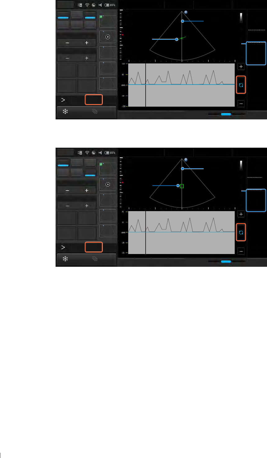
InnoSight Ultrasound System
Spectral Doppler Mode Image Controls inen
96 P6992-4, EN, 16/12/6
Drag the sample gate to the proper location
2D PW
M CW
5
Zoom
-60,0,60
5
TGC
2D PW
2D
PW
1
Figure 38PW Doppler mode real-time scan
CW mode examines the flow data along the Spectral Doppler cursor rather than a small region
2D PW
M CW
5
Zoom
5
TGC
2D CW
2D
CW
1
Figure 39CW Doppler mode real-time scan
Adjusting Baseline
Adjust the zero baseline up or down in the Time Series window
Touch Baseline +/- to adjust the value Touch and hold the baseline in Time Series window, then drag the
baseline vertically to move it
Adjusting Sample Volume (SV) Size
Adjust the SV size which controls the size of the Doppler region being examined in PW mode
To adjust the SV size:
Touch SV Size +/-
Touch and hold one finger on the scan line, then flick another finger up or down

97
inen Spectral Doppler Mode Image Controls
InnoSight Ultrasound System
P6992-4, EN, 16/12/6
Adjusting Correction Angle
Adjust the correction angle to obtain accurate velocity At angles greater than , the error in the velocity
calculation is usually too large to use
To toggle the angle between -6 and 6, touch Angle -60,0,60 repeatedly
To manually adjust the angle, touch and hold one finger on the scan line, then flick another finger to the
left or right
Updating the 2D Display
Select whether or not to continue scanning the anatomy while acquiring PW Doppler scan data
Touch Duplex to enable/disable this function

InnoSight Ultrasound System
Spectral Doppler Mode Image Controls inen
98 P6992-4, EN, 16/12/6

99
eiinndeie Customizing Your System
8
P6992-4, EN, 16/12/6
8 System Customization and Service
Customizing Your System
You can customize your system to streamline your workflow and increase efficiency Use the setup tools to
adjust sets of controls for defaults and other settings
On the system, touch Menu > Settings The setup tools are categorized into various sections Touch each
section to access the settings
General
Dock Control Panel at: Set the control panel at the left or right side of the screen
Enable freeze gesture: Enable double-tapping the screen to freeze the real-time scan
Language: Set the system language, and the system restarts automatically
Export Settings/Import Settings: Insert an external storage, touch Export/Import and select the storage
directory
Preset
Default preset/Preset list: Touch Edit, set the default preset and re-arrange the preset list on the Preset
screen, then touch Save (See Selecting a Preset on page 2)
Export preset/Import preset: Export/import customized presets to/from your external storage (See
Selecting a Preset on page 2)
Patient
Auto-create Patient Name and ID: Enable creating a set of patient name and ID every time you start a
new exam
Show Patient Information: If you want to protect patient privacy, disable this function to conceal
patient information during real-time scanning However, the system does not allow acquiring images/
loops without patient name
Show Study Information: If you want to protect physician privacy, disable this function to conceal
physician and institution information during real-time scanning
Patient Information Unit: Set the measurement unit for filling in patient information
Exam
Add logos and names for the institutions and physicians
Delete exams before: Set the number of weeks ago the exams are done, then touch Delete > OK
Workflow
Screen after Enter Ultrasound: Select the screen to enter after starting/logging in the system
Auto-freeze after Minutes: Set the number of minutes of waiting before the scan is frozen
automatically
Status after Freeze: Assign the first action to perform after freezing the scan

InnoSight Ultrasound System
Customizing Your System eiinndeie
1 P6992-4, EN, 16/12/6
Body mark
Auto-clear Body Mark after Unfreeze: Enable clearing the body mark added automatically after
returning to the real-time scan
Auto-add Body Mark after Live Scan: Enable adding a body mark each time you start a new scan
Annotation
Auto-clear Annotation after Unfreeze: Enable clearing all the annotations added automatically after
returning to the real-time scan
Measurement
Auto-clear Measurement after Unfreeze: Enable clearing all the measurements added automatically
after returning to the real-time scan
Continue Next Measurement: Enable initiating a second measurement automatically after the first one
is complete
Exam
Screen after End Exam: Select the screen to enter after touching End Exam
Export DICOM after End Exam: Enable exporting data via DICOM automatically after touching End
Exam
Print
Print while Save: Enable printing out the scanned image automatically after touching Save
Function ey
The system provides a function (configurable) key for quick access to your frequently used action
Function Key Actions: Touch Edit, assign a desired action to the function key, then touch Save
Function Key Display Name: Edit the name for the function key
Imaging
Auto Focus by following CROI/Auto CROI by following SV: Enable re-positioning ROI to the center of
the image automatically upon entering Color/CPA/PW/CW modes
Auto Zoom-in Image for PW/CW Mode/Auto Zoom-in Ratio: Enable zooming-in images automatically
with the assigned ratio upon entering PW/CW modes To change the zoom ratio, select a desired
percentage
Image format: Select the scanned image format
Cine Loop Length in Seconds (Length may vary depending on frame rate): Set the cine loop length for
each recording
PW Output Unit/CW Output Unit: Set the velocity display unit in PW/CW modes
Display Layout
M Mode Display Format/PW Mode Display Format/CW Mode Display Format: Set the aspect ratio
between the 2D imaging window and the time series window on the imaging screen
Annotation
Annotation Font Size/Arrow Size: Select a desired size

11
eiinndeie Customizing Your System
InnoSight Ultrasound System
P6992-4, EN, 16/12/6
Label List: Touch Edit, select an application and check/uncheck each label to re-arrange the label list,
then touch Save
Body Mark
Default Body Mark for Application: Touch Edit, select an application and touch a desired body mark to
set it as default, then touch Save
Body Mark List: Touch Edit, select an application and enable/disable each body mark to re-arrange the
body mark list, then touch Save
Measurement
User Defined Measurement List/User Defined Calculation List: Customize measurements/calculations
Touch Edit Select a scan mode to display its available measurements/calculations
»To add a new measurement/calculation, touch New, or use existing measurement types/equations
by selecting a measurement/calculation and touching Copy Edit the measurement/calculation name
and measurement types/equations using the Properties buttons, then touch Apply
»To edit or delete a customized measurement/calculation, select the measurement/calculation and
touch Edit or Delete
Configuration of Calculation List: Touch Edit and check/uncheck each item to re-arrange the calculation
list, then touch Save
Result Unit: Set the measurement unit
Caliper Size/Set Result Font Size: Select options
Show Measure Line: Enable showing the measuring lines while performing a measurement
Result Position: Set the position of the measured results
Show Result: Set whether to show all or the last measured results, or to hide them all
Report
Default Report Template: Set the default report template based on the application selected
Built-in Prompt String/Built-in Finding String/Built-in Comment String: Touch Edit, then edit or add
built-in strings used in the report
Report Display: Touch Edit, and select the display unit of the Calculation Package in the report
DICOM
Configure DICOM settings For more information, see DICOM Configuration on page 66
Networking
Display the network connection status of the system in the Information window
»Current Status: The IP address currently connected
»Detailed Status: All the IP addresses and MAC addresses connected
Configure the system network
»WLAN Configurations: See Connecting the System to the Wireless Network on page 6
»Ethernet Configurations: See Connecting the System to the Network by Ethernet on page 6

InnoSight Ultrasound System
Configuring Security Policies eiinndeie
12 P6992-4, EN, 16/12/6
Print
Image Printer/Report Printer: Assign the printer for use when printing images/reports
Network Printing: Configure printer settings
Image Color Invert: Print out the image with colors inverted
Configuring Security Policies
After creating user accounts, the administrator needs to enable the data security feature in order to protect
patient data
Before security configuration, log in as the administrator The ID/Name of the administrator are shown in
the Current User section
Security Policies
Applying Restriction Modes
Three restriction modes are available for selection
No restriction: All the system features are available to the guest users
Only Patient data is locked: All the system features except access to ePHI information are available to
guest users
Complete system is locked: None of the system features are available to guest users
Setting the Password Policy
Enhance the user login security by applying rules to setting the password, including restricting password
length, uniqueness and complexity
Setting the Account Lockout Policy
Determine the rules of locking a user account after invalid logon attempts
Enabling Auto Log Off
Set an automated logout after a specified period of inactivity
User Management
Modify personal credentials and change roles of the users
1 Touch User Management
2 In the User List section, to modify a user, touch to delete a user, touch
Servicing your system
If you encounter any problem using the system, need to update software, backup and restore data or use
the on board diagnostic tools, select the service tools Some functionality may require access keys which
are available from technical support

13
eiinndeie Servicing your system
InnoSight Ultrasound System
P6992-4, EN, 16/12/6
On the system, touch Menu > Settings > Service The service tools are categorized into the following
sections
Managing your system: Touch System Management System information, software update and backing
up and restoring data can be found here
Testing your system: Touch Test & Utilities Use the diagnostic tools here to test the system
functionality
Exporting system logs: Touch System Logs Test results of the system functionality can be found here
About your system: Touch About The system’s main version, serial number (default password for the
first-time-logging-in) and this User Manual can be found here
Reinstalling Software
This requires further assistance, contact technical support (See Customer Service on page 3) An
access key is required Once the access key is provided, the installation will require a USB flash drive
with the software ZIP file Please allow five to ten minutes for installation The system will restart after
completed All settings and patient data are preserved but it is good practice to ensure recent backups have
been performed
Touch System Management > (Software Maintenance) > (Reinstall Software) > Update
Ensure regular backups of patient data and settings It may be important in the event of a failure
to have current configuration data
Checking the Software Version
This may be required when contacting Technical Support
Touch System Management > (Software Maintenance) > (Software Version)
Checking the System’s Serial Number
The System Serial Number is the unique Philip’s Customer Identifier It may need to be edited with
assistance from technical support when a replacement tablet is received and no backup is available to
restore from
Touch System Management > (System Information) > (System Serial Number) > Edit
Checking the Tablet’s Serial Number
List the serial number of the tablet This is assigned and cannot be changed
Touch System Management > (System Information) > (Tablet Serial Number)
Checking the License Status
List current licenses and options that are installed It may need to be reinstalled with assistance from
technical support when a replacement tablet is received and no licenses are installed
Touch System Management > (System Information) > (License Status)
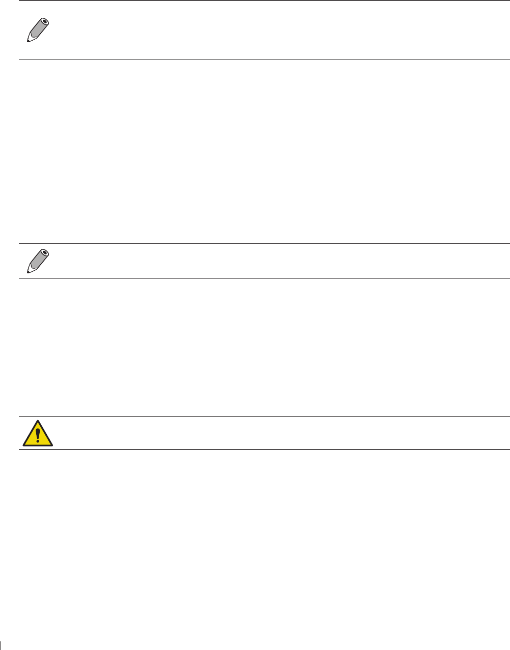
InnoSight Ultrasound System
Servicing your system eiinndeie
14 P6992-4, EN, 16/12/6
Resetting User Settings
Performing this action will reset all system settings of the current user and is irreversible Consider backing
up your settings to an external storage device first
Touch System Management > (System Configuration) > (Reset Configuration) > Reset
Backing Up System Settings and Patient Data
Before backing up system settings and patient data, ensure that the system is connected to an
external storage device
It is recommended that you perform regular backups on system settings and patient data to
prevent data loss
1 Touch System Management
2 In the System Configuration section, touch Backup in the following fields:
Backup System Settings & Patient Data: All the system settings, presets and exams are saved to the
external storage device The following file naming convention is applied to the backup file:
BackupYYYYMMDDHHMMSS
Backup Patient Data: All the exams are saved to the external storage device The following file
naming convention is applied to the backup file:
BackupPATIENTYYYYMMDD
Restoring System Settings and Patient Data
Before restoring system settings and patient data, ensure that the system is connected to an
external storage device containing stored system settings and patient data
1 Touch System Management
2 In the System Configuration section, touch Restore in the following fields, and select a backup file:
Restore System Settings & Patient Data: All the system settings, presets and exams are restored to
the system from the external storage device
Restore Patient Data: All the exams are restored to the system from the external storage device
Resetting Your System
This action is irreversible Consider backing up your up system settings and patient data to an
external storage device first
Performing this action will restore your system to its factory state and erase all your user settings and
patient data from the system storage
Touch System Management > (System Configuration) > (Factory Reset) > Erase
Testing the System
The system provides diagnostic tools to examine all the functionality of the system components However,
these operations may require assistance from technical support (See Customer Service on page 3)
Touch Test & Utilities > (System Test) > (Test mode)

1
eiinndeie Servicing your system
InnoSight Ultrasound System
P6992-4, EN, 16/12/6
Exporting System Logs
Before exporting system logs, ensure that the system is connected to an external storage device
After testing the system, the test results will be logged and available for review You can view all task
records concerning DICOM transmission from the System Logs window, or export the log file to an external
storage device and send it to your service contact (See Customer Service on page 3)
Touch System Logs > Export
Reading the User Manual
This User Manual is also available in an electronic format
Touch About > (User Manual) > Open File

InnoSight Ultrasound System
16 P6992-4, EN, 16/12/6
107
nde Transducer Maintenance
9
P6992-4, EN, 16/12/6
9 Transducers
The transducer is the most important factor in image quality Optimal imaging cannot be obtained without
the correct transducer The system is optimized for use based on your transducer selection
Transducer Maintenance
Transducers require proper care, cleaning, and handling Reasonable care includes inspection,cleaning, and
disinfection or sterilization, as necessary Inspect the transducer, cable, and lens before each use Check for
cracks or other damage that jeopardizes the integrity of the transducer Report any transducer damage to
your Philips representative, and discontinue use of the transducer
For all information on transducer cleaning and disinfection, see Chapter 1 Transducer Care on
page 111
For all information about the use of acoustic coupling gels, see Ultrasound Transmission Gels on
page 11
If you encounter poor image quality or transducer problems, see Troubleshooting on page 123
Some ultrasound coupling gels, as well as some solutions for pre-cleaning, disinfecting, and
sterilizing can damage a transducer Before using a gel or solution on a transducer, see Ultrasound
Transmission Gels on page 11 or Chapter 1 Transducer Care on page 111 You can also
contact your local Philips representative For contact information, see Customer Service on
page 3
Acoustic artifacts
The transducer adds its own signature to the echo information in the form of beam width effects, axial
resolution limitations, and frequency characteristics The control choices made by the sonographer that
affect amplification, signal processing, and echo signal display can lead to significant differences in the
displayed appearance of echo data Following is a brief discussion of acoustic artifacts An understanding
of the physical basis for the production of signals displayed on ultrasound images is helpful in minimizing
artifacts on images and interpreting the results of studies
An artifact is an echo displayed in a different position than its corresponding reflector in the body
Artifacts can also be caused by intervening tissue properties Artifacts can originate from external noise,
reverberations, multi-path reflections, or misadjusted equipment They can also come from the ultrasonic
beam geometry and unusual changes in beam intensity Artifacts and their manifestations are listed below,
and following are some definitions of various artifacts
Added objects displayed as speckle, section thickness, reverberation, mirror image, comet tail, or ring
down
Missing objects due to poor resolution
Incorrect object brightness due to shadowing or enhancement
Incorrect object location due to refraction, multi-path reflections, side lobes, grating lobes,speed error,
or range ambiguity
Incorrect object size due to poor resolution, refraction, or speed error
Incorrect object shape due to poor resolution, refraction, or speed error

InnoSight Ultrasound System
nde Acoustic artifacts
108 P6992-4, EN, 16/12/6
Acoustic saturation occurs when received signals reach a system’s high-amplitude limit At that point the
system becomes unable to distinguish or display signal intensities At the point of saturation, increased
input will not increase output
Aliasing occurs when the detected Doppler frequency exceeds the Nyquist limit It is characterized on the
spectral display by the Doppler peaks going off the display, top or bottom, and then continuing on the other
side of the baseline On the Color display an immediate change in color from one Nyquist limit to the other
is seen
Comet tail is a form of reverberation artifact produced when two or more strong reflectors are close
together and have a high propagation speed In this case, sound does not travel directly to a reflector and
back to the transducer and a strong linear echo appears at the reflector and extends deeper than the
reflector
Enhancement is an increased relative amplitude of echoes caused by an intervening structure of low
attenuation Focal enhancement, also known as focal banding, is the increased intensity in the focal region
that appears as a brightening of the echoes on the display
Mirror imaging artifact is most commonly seen around the diaphragm this artifact results from sound
reflecting off another reflector and back
Mirroring is the appearance of artifacts on a spectral display when there is improper separation of forward
and reverse signal processing channels Consequently, strong signals from one channel mirror into the
other
Multi-path positioning and refraction artifacts describe the situation in which the paths to and from a
reflector are different The longer the sound takes traveling to or from a reflector, the greater the axial
error in reflector positioning (increased range) Refraction and multi-path positioning errors are normally
relatively small and contribute to general degradation of the image rather than to gross errors in object
location
Propagation speed errors occur when the assumed value for propagation speed by the ultrasound system
is incorrect If the actual speed is greater than that assumed, the calculated distance to a reflector is too
small, and the reflector will be displayed too far from the transducer Speed error can cause a structure to
be displayed with incorrect size and shape
Range ambiguity can occur when reflections are received after the next pulse is transmitted In ultrasound
imaging, it is assumed that for each pulse produced, all reflections are received before the next pulse is sent
out The ultrasound system calculates the distance to a reflect or from the echo arrival time assuming that
all echoes were generated by the last emitted pulse The maximum depth to be imaged unambiguously by
the system determines its maximum pulse repetition frequency
Reverberation is the continuing reception of a particular signal because of reverberation rather than
reflection from a particular acoustic interface This phenomenon is analogous to the effect created by
mirrors positioned on opposite walls when an object, a head for instance, is placed between the mirrors
The image of the head is reflected back and forth infinitely between the two mirrors, creating the optical
illusion of multiple heads Reverberations are easily identifiable, because they are equally spaced on the
display
Scattering is the diffuse, low-amplitude sound waves that occur when acoustic energy reflects off tissue
interfaces smaller than a wavelength In diagnostic ultrasound, Doppler signals come primarily from
acoustic energy back-scattered from red blood cells
Shadowing is the reduction in echo amplitude from reflectors that lie behind a strongly reflecting or
attenuating structure This phenomenon occurs when scanning a lesion or structure with an attenuation
rate higher than that of the surrounding tissue The lesion causes a decrease in beam intensity, which
results in decreased echo signals from the structures beyond the lesion Consequently, a dark cloud behind
the lesion image forms on the display This cloud, or shadow, is useful as a diagnostic clue
Side lobes (from single-element transducers) and grating lobes (from array transducers) cause objects that
are not directly in front of the transducer to be displayed incorrectly in lateral position
109
nde Transducer Covers
InnoSight Ultrasound System
P6992-4, EN, 16/12/6
Speckle appears as tissue texture close to the transducer but does not correspond to scatterers in tissue It
is produced by ultrasound wave interference and results in general image degradation
Spectral broadening is a display phenomenon that occurs when the number of energy-bearing Fourier
frequency components increases at any given point in time As a consequence, the spectral display is
broadened Spectral broadening can indicate the disturbed flow caused by a lesion, and therefore it is
important diagnostically However, broadening can also result from interaction between flow and sample
volume size, in which case it is an artifact
Speed of sound artifacts occur if the sound propagation path to a reflector is partially through bone, and
the speed of sound is greater than in the average soft tissue Echo position registration artifacts will be
produced Reflectors appear closer to the transducer than their actual distance because of this greater
speed of sound, resulting in a shorter echo transit time than for paths not containing bone
Transducer Covers
To prevent contamination by blood-borne pathogens, sterile transducer covers are required for
intraoperative procedures in China, sterile covers are also required for transrectal and intravaginal
procedures the protective covers are mandatory in China and apan We recommend the use of qualified
covers
Latex and talc are commonly used in sheaths marketed to help with infection control in endocavity
and intraoperative imaging applications Examine the packaging to confirm latex and talc content
Studies have shown that patients can experience allergic reactions with natural rubber latex See
the FDA Medical Alert, March 29, 1991, reprinted in FDA Medical Alert on Latex on page 21
In intraoperative applications, sterilized transducers should be used with sterile gel and a
sterile transducer cover
Sterile transducer covers are disposable and must not be reused
Inspect transducer covers before and after use
Do not apply the transducer cover until you are ready to perform the procedure
If an installed transducer cover is cut or contaminated before use, the transducer should be
cleaned and disinfected or sterilized, and a new sterile cover installed
When using C9-4v endocavity transducers, the transducers must be protected with a transducer
sheath
If a sterile transducer cover becomes compromised during an intraoperative application involving
a patient with transmissible spongiform encephalopathy, such as Creutzfeldt-akob disease,
follow the guidelines of the US Centers for Disease Control and this document from the World
Health Organization: WHO/CDS/ APH/2/3, WHO Infection Control Guidelines for Transmissible
Spongiform Encephalopathies The transducers for your system cannot be decontaminated using
a heat process

InnoSight Ultrasound System
nde Transducer Storage
110 P6992-4, EN, 16/12/6
Transducer Storage
Use the appropriate guidelines for storing transducers for transport, and daily and long-term storage For
information on temperature and humidity requirements, see Appendix A: Specifications on page 12
Storage for Transport
If a carrying case is provided with your transducer, always use the carrying case to transport the transducer
from one site to another Follow these guidelines to properly store transducers for transport:
Make sure that the transducer is clean and disinfected before placing it in the case to avoid
contaminating the foam that lines the carrying case
Place the transducer in the case carefully to prevent kinking of the cable
Before closing the lid, make sure no part of the transducer is protruding from the case
Wrap the case in plastic material containing air-filled pockets (such as Bubble Wrap material), and pack
the wrapped case in a cardboard carton
Daily and Long-Term Storage
Follow these guidelines to protect your transducer:
Always store transducers in the transducer holders on your system cart or on a securely mounted wall
rack when you are not using them
Ensure the transducer holders are clean before storing transducers
Avoid storing transducers in areas of temperature extremes or in direct sunlight
Store transducers separately from other instruments to avoid inadvertent transducer damage
Before storing transducers, make sure they are thoroughly dry
111
1 ndee Transducer Care and Operator Safety
10
P6992-4, EN, 16/12/6
10 Transducer Care
All Philips transducers require proper care, cleaning, and handling This section contains information
and instructions to help you effectively clean, disinfect, and sterilize the transducers that are compatible
with your system Additionally, these instructions help avoid damage during cleaning, disinfection, and
sterilization, which could void your warranty
Reasonable care includes inspection, cleaning, and disinfection or sterilization, as necessary Transducers
must be cleaned after each use Inspect all parts of the transducer carefully before each use Check for
cracks or other damage that jeopardizes the integrity of the transducer
Transducer Care and Operator Safety
Observe the following warnings and cautions during all cleaning, disinfection, and sterilization procedures
and when using disinfectants More specific warnings and cautions are included within the care and
cleaning procedures and on the labels of the cleaning or disinfection solutions
Disinfectants are recommended because of their chemical compatibility with product materials,
not their biological effectiveness For the biological effectiveness of a disinfectant, see the
guidelines and recommendations of the disinfectant manufacturer, the US Food and Drug
Administration, and the US Centers for Disease Control
The level of disinfection required for a device is dictated by the type of tissue it will contact during
use Ensure the disinfectant type is appropriate for the type of transducer and the transducer
application For information on the levels of disinfection requirements, see Transducer Care
Methods on page 113 Also, see the disinfectant label instructions and the recommendations of
the Association for Professionals in Infection Control, the US Food and Drug Administration, and
the US Centers for Disease Control
Do not drop the transducer on the hard surface, as this will damage the transducer elements
and compromise the electrical safety of the transducer
Avoid kinking or pinching the transducer cable
Do not allow sharp objects, such as scissors, scalpels, or cauterizing knives, to touch
transducers or cables
Do not use damaged or flawed transducers
Do not expose transducers to direct heat such as strong sunlight or local heat sources Heat ages
the crystal and causes loss of sensitivity
Transducers are highly-sensitive instruments and are easily damaged due to improper
operations Use the transducers with extra care and avoid damages when not in use
Perform regular testing and periodic maintenance including inspection of the transducer
assembly for cracks that allow the ingress of conductive fluid
Do not immerse the transducer into liquids beyond its binding line, and never immerse the
transducer connector into any liquids
Use only the approved ultrasound coupling gels
Use only couplants specifically designed for ultrasound examinations Do not use mineral-oil or
vegetable-based couplants, which can damage transducers
InnoSight Ultrasound System
ndee Transducer Care and Operator Safety
112 P6992-4, EN, 16/12/6
If a pre-mixed solution is used, be sure to observe the solution expiration date
Transducers must be cleaned after each use Cleaning the transducer is an essential step
before effective disinfection or sterilization Be sure to follow the manufacturer’s instructions
when using disinfectants
When sterilizing a transducer, ensure that the sterilant solution’s strength and duration of
contact are appropriate for sterilization Be sure to follow the manufacturer’s instructions
Follow the recommendations of the disinfectant manufacturer
Attempting to clean or disinfect a transducer, cable, or connector by using a method other than
the procedures provided here can damage the device and voids the warranty
Do not use a surgeon’s brush when cleaning transducers Even the use of soft brushes can
damage transducers
Do not use a brush on the transducer label
Do not use paper products or products that are abrasive when cleaning the transducer They
damage the soft lens of the acoustic window of the transducer
During cleaning, disinfection, and sterilization, orient the connector and cable that must remain
dry higher than the wet parts, until all parts are dry This helps keep liquid from entering unsealed
areas of the transducer
When cleaning and disinfecting transducers, do not allow any fluid to enter electrical
connections or metal portions of the connector Damage due to fluids in these areas is not
covered by the warranty or your service contract
To keep fluids from entering the transducer, do not disconnect the cable from the transducer
during cleaning and disinfection
When using an enzymatic cleaner, be sure to use the proper concentration and rinse thoroughly
Before storing transducers, ensure that they are thoroughly dry If it is necessary to dry the
transducer lens or acoustic window after cleaning, use a soft cloth and a blotting motion, instead
of a wiping motion
Using non-recommended disinfectants, using incorrect solution strengths, or immersing a
transducer deeper or longer than recommended can damage or discolor the transducer and
void the transducer warranty
Use only liquid solutions to sterilize transducers Using autoclave, gas (EtO), or other methods
not approved by Philips will damage your transducer and void your warranty
Do not soak the transducer for extended periods of time Limit the time and depth that
transducers are soaked in disinfectant solution to the minimum time recommended by the
disinfectant manufacturer
For information on ordering transducer supplies, contact CIVCO Medical Solutions (See Supplies and
Accessories on page 3)
113
1 ndee Inspecting the Transducer
InnoSight Ultrasound System
P6992-4, EN, 16/12/6
Latex Product Alert
Transducer covers may contain natural rubber latex Those covers may cause allergic reactions in
some individuals
For information on allergic reactions to latex-containing medical devices, see FDA Medical Alert on Latex
on page 21
Inspecting the Transducer
Inspect the transducer’s acoustic lens, outer cover, the cable, and the transducer connector before each
use Check the transducer carefully and see if there are cracks, cuts, or any other damages which may admit
fluids Do not use the transducer if it is damaged
If the transducer is dropped, examine it immediately for signs of damage Perform a sample scan to make
sure it operates correctly Contact Philips for service or replacement if any abnormalities are found For
more information on transducer care, refer to the Philips Transducer Care website:
wwwPhilipscom/transducercare
To avoid any possibilities of hurting the patient, check if the transducer has a smooth edge and an
even surface before each use
Transducer Care Methods
Transducer care methods are based on the use of the transducer For more information on transducer care,
refer to the Philips Transducer Care website:
wwwPhilipscom/transducercare
Care Methods by Transducer Use
Transducer Use Example Classification Care Method
Contact intact skin Curved, linear, and
sector transducers Noncritical Low-level disinfection
Contacts mucous
membranes Endocavity transducer Semi-critical High-level disinfection
The care method for your transducer determines the appropriate disinfectant for your transducer
Transducer and Cable Cleaning
These general cleaning instructions are indicated for all supported transducers, cables, and connectors It
is important that you clean the transducer, cable, and connector according to the following procedures
Before cleaning a transducer, read Chapter 2 Safety Information on page 9 and Transducer Care and
Operator Safety on page 111 After cleaning, you must disinfect or sterilize transducers by following the
appropriate procedures

InnoSight Ultrasound System
ndee Low-Level Disinfecting of Transducers
114 P6992-4, EN, 16/12/6
Always use protective eyewear and gloves when cleaning and disinfecting any equipment
When cleaning and disinfecting transducers, do not allow any fluid to enter electrical
connections or metal portions of the connector Damage due to fluids in these areas is not
covered by the warranty or your service contract
Cleaning Instructions
1 After every patient exam, use a moist cloth to remove the ultrasound transmission gel from the
transducer
2 Disconnect the transducer from the system, and remove any accessories attached to or covering the
transducer
3 To remove all organic matter and other residue, use a pre-cleaner or detergent to assist in removing
protein residuals Enzymatic cleaners must be diluted prior to use per the manufacturer’s instructions
for dilution Enzymatic cleaners are generically approved for use
4 When cleaning the lens, use a blotting motion rather than a wiping motion
To remove remaining particulate and cleaning residue, use cleaning wipes according to the
manufacturer’s instructions You may rinse thoroughly with water up to the immersion point shown in
the figure following the procedure The transducer may be immersed up to the immersion point No
other part of the transducer, cable, or connector can be soaked or immersed in fluids
Immersion
point
Figure 40Immersion point for surface transducers (Example transducer-C6-2)
Do not immerse beyond this point, cm (2 in) from the strain relief this is the maximum allowable
immersion of the cable you are not required to immerse to this point if it is unnecessary
6 Wipe with a dry cloth if necessary To dry the lens, use a soft cloth and a blotting motion instead of a
wiping motion
Examine the device and cable for damage such as cracks, splitting, sharp edges, or projections If
damage is evident, discontinue use of the device and contact your Philips representative
If you use cleaning wipes, it may be unnecessary to rinse the transducer with water Always
follow the product label recommendations
Low-Level Disinfecting of Transducers
Low-level disinfection of transducers uses the spray or wipe method, with a low-level or intermediate-level
disinfectant
1 Clean the transducer and cable according to the procedures in Transducer and Cable Cleaning on
page 113 Observe all warnings and cautions
2 After cleaning, choose the low- or intermediate-level disinfection solutions compatible with your
transducer, cable, and connector For a list of disinfectants compatible with your transducer,

115
1 ndee High-Level Disinfecting of Transducers
InnoSight Ultrasound System
P6992-4, EN, 16/12/6
see Ultrasound Transmission Gels on page 11 Follow the label instructions for preparation,
temperature, solution strength and duration of contact Ensure that the solution strength and duration
of contact are appropriate for the intended clinical use of the device If a pre-mixed solution is used, be
sure to observe the solution expiration date
3 Wipe or spray the transducer, cable, strain relief, and connector with the disinfectant, following the
disinfectant label instructions for temperature, wipe durations, and duration of disinfectant contact
Ensure that the disinfectant solution does not enter the device or the connector Do not allow any type
of fluid to enter the connector Ensure that fluid does not enter through the strain relief, through the
connector, or through the electrical contacts Fluid in the connector may void the device warranty
4 Air dry or towel dry with a sterile cloth according to the instructions on the disinfectant label
Examine the transducer for damage, such as cracks, splitting, fluid leaks, or sharp edges or projections
If damage is evident, discontinue use of the transducer and contact your Philips representative
High-Level Disinfecting of Transducers
High-level disinfection of transducers typically uses an immersion method
1 Clean the transducer and cable according to the procedures in Transducer and Cable Cleaning on
page 113 Observe all warnings and cautions
2 After cleaning, choose the high-level disinfection solutions compatible with your transducer, cable, and
connector For a list of disinfectants compatible with your transducer, see Ultrasound Transmission
Gels on page 11 Follow the label instructions for preparation, temperature, solution strength and
duration of contact Ensure that the solution strength and duration of contact are appropriate for the
intended clinical use of the device If a pre-mixed solution is used, be sure to observe the solution
expiration date
3 Using an appropriate disinfectant for the transducer cable, wipe or spray the cable, strain relief,and
connector, following disinfectant label instructions for temperature, wipe durations, solution strengths,
and duration of disinfectant contact Ensure that the disinfectant solution does not enter the device or
the connector When disinfecting the transducer cable, wipe or spray only the outer surfaces do not
allow any type of fluid to enter through the strain relief or electrical contacts
4 Immerse the transducer into the appropriate disinfectant for your transducer as shown in the figure
following the procedure Follow the instructions on the disinfectant label for the duration of transducer
immersion Do not immerse transducers longer than the minimum time needed for your level of
disinfection The transducer may be immersed up to the immersion point shown in the figure following
the procedure No other part of the transducer or transducer cable can be soaked or immersed in fluids
Using the instructions on the disinfectant label, rinse the transducer up to the point of immersion Do
not soak or immerse any other part of the transducer or cable
6 Air dry or towel dry with a sterile cloth according to the instructions on the disinfectant label
Examine the transducer for damage, such as cracks, splitting, fluid leaks, or sharp edges or projections
If damage is evident, discontinue use of the transducer and contact your Philips representative
Ultrasound Transmission Gels
For proper transmission of the acoustic beam, use the ultrasound transmission gel supplied by or
recommended by Philips, or another glycol-, glycerol-, or water-based acoustic coupling medium
For intraoperative applications, use only the Sterile Aquasonic or Sterile Ultraphonic gel provided
with the transducer cover
InnoSight Ultrasound System
ndee Compatible Disinfectants and Cleaning Solutions
116 P6992-4, EN, 16/12/6
Do not use hand sanitizing gels
Do not apply the transducer gel until you are ready to perform the procedure Transducers should
not be left soaking in gel
Gels listed here are recommended because of their chemical compatibility with product materials
Some recommended gels include:
Aquasonic 1
Aquasonic Clear
Carbogel-ULT
ECG Gel (Nicom)
Nemidon Gel
Scan
Compatible Disinfectants and Cleaning Solutions
The following table lists the disinfectants and cleaning solutions compatible with the transducers available
for the system
The only parts of the transducer that may be cleaned with isopropyl alcohol are the transducer
housing and lens or acoustic window Ensure that the solution is only alcohol or less Do
not wipe any other part of a transducer with isopropyl alcohol (including cables, connectors, or
strain reliefs), as it can damage those parts of the transducer This damage is not covered by the
warranty or your service contract
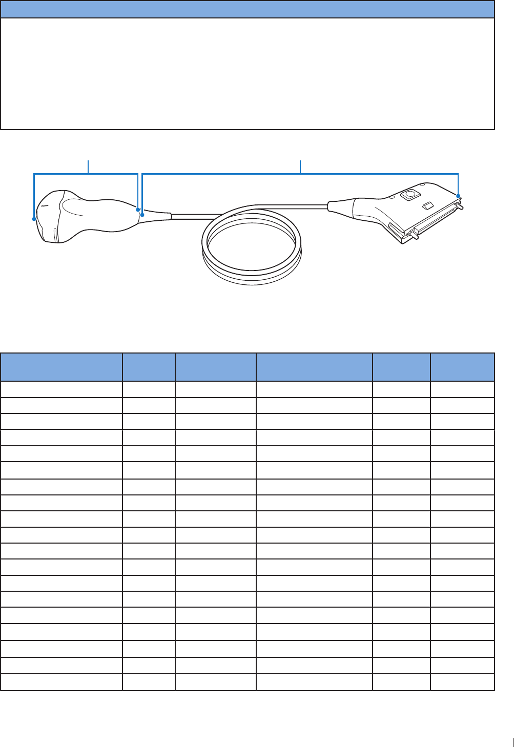
117
1 ndee Compatible Disinfectants and Cleaning Solutions
InnoSight Ultrasound System
P6992-4, EN, 16/12/6
Disinfectants and Cleaning Solutions Table Legend
Country of Origin Disinfectant Type Compatibility
AU Australia
CA Canada
DE Germany
ES Spain
FR France
P apan
U United ingdom
US United States
CL Cleaner
HLD High-level disinfectant
ILD Intermediate-level
disinfectant
LLD Low-level disinfectant
S Sterilant
C Approved for use on the cable
and connector (never immerse or
soak a connector)
T Approved for use on the
transducer
N Not approved for use
T (Transducer) C (Cable, connector and strain reliefs)
Figure 41Transducer parts (Example transducer: C6-2)
Disinfectants and Cleaning Solutions Compatibility
Solution Country of
Origin
Qualified Use Active Ingredient Disinfectant
Type
Compatibility
Isopropyl Alcohol All Spray/Wipe Alcohol LLD, ILD T
AbcoCide US SoakaGlutaraldehyde HLD, S T
AbcoCide 2 US SoakaGlutaraldehyde HLD, S T
Accel Wipes (all types) CA Wipe Hydrogen Peroxide LLD, ILD T
Acecide JP SoakaPeracetic Acid HLD, S N
Aidal Plus AU SoakaGlutaraldehyde HLD, S T
Alkaspray FR Spray/Wipe Alcohol, Alkylamine LLD, ILD T
Ampholysine Basique FR Spray/Wipe Biguanide/QUAT LLD, ILD T
Aniosept Activ FR SoakaPeracetic Acid HLD, S T
ANIOY DM FR SoakaPeracetic Acid HLD, S T
Anioxyde 1 FR SoakaPeracetic Acid HLD T
Antigermix E1 FR E1 System UV-C HLD N
Antigermix S1 FR S1 System UV-C HLD T
Banicide Plus US SoakaGlutaraldehyde HLD, S T
Bleach (6 NaOCl Max) All Spray/Wipe Sodium Hypochlorite LLD, ILD T
CaviWipes US Wipe Alcohol, QUAT LLD, ILD T
Cidex US SoakaGlutaraldehyde HLD, S T
Cidex US SoakaGlutaraldehyde HLD, S T
Cidex OPA US SoakaOrtho-phthalaldehyde HLD T

InnoSight Ultrasound System
ndee Compatible Disinfectants and Cleaning Solutions
11 P6992-4, EN, 16/12/6
Solution Country of
Origin
Qualified Use Active Ingredient Disinfectant
Type
Compatibility
Cidex PAE 14 FR SoakaGlutaraldehyde HLD, S T
Cidex Plus US SoakaGlutaraldehyde HLD, S T
Cleanisept Wipes DE Spray/Wipe QUAT LLD, ILD T
Clorox Healthcare Bleach
Germicidal Cleaner US Spray/Wipe Sodium Hypochlorite LLD, ILD T
Clorox Healthcare
Hydrogen Peroxide Cleaner
Disinfectants
US Spray/Wipe Hydrogen Peroxide LLD, ILD T
Combi-Instruments-N FR SoakaGlutaraldehyde-
formacetale blend HLD T
Descoton Extra DE SoakaGlutaraldehyde HLD, S T
Dispatch US Spray/Wipe Sodium Hypochlorite LLD, ILD T
Endosporine FR SoakaGlutaraldehyde HLD, S T
Enzol US Pre-cleaner Enzymes Cleaner T
Epizyme Rapid AU Pre-Cleaner Enzymes Cleaner T
Gigasept FF (neu) DE SoakaSuccinic dialdehyde HLD T
Gigasept PA DE SoakaPeracetic Acid HLD N
Gigasept PAA Concentrate DE SoakaPeracetic Acid HLD N
Incidin DE Spray/Wipe Alcohol LLD, ILD T
Incidur Spray DE Spray/Wipe Alcohol, QUAT, Aldehyde LLD, ILD T
Instruzyme FR Pre-cleaner Enzymes, QUAT,
Biguanide Cleaner T
lenzyme US Pre-cleaner Enzymes Cleaner T
orsolex Basic FR SoakaAldehyde Releasing HLD T
orsolex Extra FR SoakaAldehydes/QUAT HLD T
orsolex PAE FR SoakaGlutaraldehyde HLD, S T
MaxiCide Plus US SoakaGlutaraldehyde HLD, S T
MedDis U SoakaQUAT, Sulfamic Acid HLD T
Medistel U SoakaQUAT, Sulfamic Acid HLD T
Medizyme AU SoakaEnzymes Cleaner T
MetriCide US SoakaGlutaraldehyde HLD, S T
MetriCide 2 US SoakaGlutaraldehyde HLD, S T
MetriCide OPA Plus US SoakaOrtho-phthalaldehyde HLD T
MetriCide Plus 3 US SoakaGlutaraldehyde HLD, S T
MetriZyme US Pre-cleaner Enzymes Cleaner T
mikrozid PAA wipes DE Wipe Peracetic Acid LLD, ILD T
Mild Soap Solution All Pre-cleaner Surfactants/Soap Cleaner T
Milton AU Spray/Wipe Sodium Hypochlorite LLD, ILD T
NDP Med Concentrated
Plus ES SoakaN-Duopropenide,
Alkylamine HLD T
neodisher endo CLEAN/
neodisher endo SEPT PAC DE AER Cleaner/Peracetic Acid HLD N

119
1 ndee Compatible Disinfectants and Cleaning Solutions
InnoSight Ultrasound System
P6992-4, EN, 16/12/6
Solution Country of
Origin
Qualified Use Active Ingredient Disinfectant
Type
Compatibility
neodisher endo DIS active DE SoakaPeracetic Acid HLD T
Olympic Peracetic Acid U AER Peracetic Acid HLD N
Omnicide 14NS US SoakaGlutaraldehyde HLD, S T
Omnicide 2 US SoakaGlutaraldehyde HLD, S T
OPAL AU SoakaOrtho-phthalaldehyde HLD T
Opticide3 US Spray/Wipe Alcohol, QUAT LLD, ILD T
Oxivir (all types) US Wipe Hydrogen Peroxide LLD, ILD T
Oxygenon-I FR SoakaOxygen Generating HLD T
PeraSafe U SoakaPeracetic Acid HLD, S T
Perascope U SoakaPeracetic Acid HLD T
Perastel U AER/SoakaPeracetic Acid HLD T
PerCept (all types) CA Wipe Hydrogen Peroxide LLD, ILD T
Phagocide D FR SoakaGlutaraldehyde HLD, S T
Phagozyme ND FR Pre-cleaner Enzymes, QUAT Cleaner T
PI-Spray (Formerly T-Spray) US Spray/Wipe QUAT LLD, ILD T
PI-Spray II (Formerly
T-Spray II) US Spray/Wipe QUAT LLD, ILD T
ProCide-D US SoakaGlutaraldehyde HLD, S T
ProCide-D Plus US SoakaGlutaraldehyde HLD, S T
Prolystica 2 US Pre-cleaner Enzymes Cleaner T
Protex Disinfectant (All
Types) US Spray/Wipe QUAT LLD, ILD T
Quaternary Ammonium
(Active Max) All Spray/Wipe QUAT LLD, ILD T
Rapicide US SoakaGlutaraldehyde HLD, S T
Rapicide OPA US SoakaOrtho-phthalaldehyde HLD T
Rapicide PA US SoakaPeracetic Acid HLD T
Revital-Ox Resert L HLD US SoakaHydrogen Peroxide HLD T
Rivascop FR Spray/Wipe QUAT LLD, ILD T
Salvanios pH 1 FR Spray/Wipe QUAT LLD, ILD T
Sani-Cloth Active DE Wipe QUAT LLD, ILD T
Sani-Cloth AF US Wipe QUAT LLD, ILD T
Sani-Cloth AF3 US Wipe QUAT LLD, ILD T
Sani-Cloth Bleach US Wipe Sodium Hypochlorite LLD, ILD T
Sani-Cloth HB US Wipe QUAT LLD, ILD T
Sanicloth Plus US Wipe Alcohol, QUAT LLD, ILD T
Sekucid N FR SoakaGlutaraldehyde HLD, S T
Sekusept Aktiv DE SoakaPeracetic Acid HLD T
Sekusept Easy DE SoakaPeracetic Acid HLD T
Sekusept Plus DE SoakaGlucoprotamine HLD T
Soluscope P FR AER Peracetic Acid HLD N
Steranios 2 FR SoakaGlutaraldehyde HLD, S T

InnoSight Ultrasound System
ndee Compatible Disinfectants and Cleaning Solutions
120 P6992-4, EN, 16/12/6
Solution Country of
Origin
Qualified Use Active Ingredient Disinfectant
Type
Compatibility
Sterrad 1S US Reprocessor (S) Hydrogen Peroxide S N
TD- US TD-1
Reprocessor Glutaraldehyde HLD, S N
Tristel Duo U Foam/Wipe Chlorine Dioxide HLD T
Tristel Fuse for Instruments U Stella System Chlorine Dioxide HLD T
Tristel Multi-Shot U SoakaChlorine Dioxide HLD T
Tristel Sporicidal Wipes U Wipe Chlorine Dioxide HLD T
Tristel Trio Trace U
Pre-clean wipe,
sporicidal wipe,
rinse wipe
Enzymes Chlorine Dioxide HLD T
Trophon EPR AU Trophopn EPR
Reprocessor Hydrogen Peroxide HLD T
Vaposeptol FR Spray/Wipe Alcohol, Biguanide LLD, ILD T
Virox RTU CA Wipe Hydrogen Peroxide LLD, ILD T
Wavicide -1 US SoakaGlutaraldehyde HLD, S T
Wip’Anios FR Wipe Alcohol, QUAT LLD, ILD T
aNever immerse or soak a connector
121
11 einenne Cleaning the System
11
P6992-4, EN, 16/12/6
11 System Maintenance
Maintenance should be performed regularly and as needed
Cleaning the System
The system and peripherals are medical electrical equipments and require thorough cleaning If exposed to
constant and excessive environmental dust and humidity, both performance and reliability of these devices
will be suffered Clean the power adapter, ventilation slots, all connection ports/sockets and the touch
screen regularly or whenever you observe dust or other particles
For information on transducer cleaning and disinfection, see Chapter 1 Transducer Care
Before cleaning the system, perform the following operations to avoid the risk of electric shock
1 Turn off the system power
2 Disconnect the power adapter from the system and the power outlet
Running the system for a long period of time may generate excessive heat Do not clean the
system until it completely cools down
Cleaning the System/System Cart Surfaces
The system connection ports, external monitor port, power adapter port and other openings in the
enclosure are most likely to be affected by liquid spills and other materials such as excessive amounts
of gel These materials may seep into electrical components under the enclosure and cause intermittent
failures During preventive maintenance, look for potential problems, such as gaps or cracks
1 Gently wipe the system/cart surfaces with a lint-free, non-abrasive and dry cloth
2 Moisten the cloth with soapy water and gently wipe it across the surfaces in one direction
Moving the cloth back and forth on the touch screen will damage the screen
3 Remove any solid matter around the ventilation slots, connection ports, and power adapter port with a
cotton swab or toothpick to ensure that solids are not pushed into the system
4 If blood or other infectious material comes in contact with the system, cart or any cable, apply a small
amount of specific cleaning solutions or disinfectants (See page 122) to the cloth, and gently wipe it
across the surfaces in one direction Repeat the application and cleaning process several times until the
spots are dissolved
Remove any residue with a cloth moistened with sterile water
6 Wipe off any excess moisture then leave the surfaces completely dry before powering the system back
on
The compatibility of disinfection and cleaning solutions varies depending on the item on which they are
used The products in the following table are compatible with the external plastic and painted surfaces of
system and cart
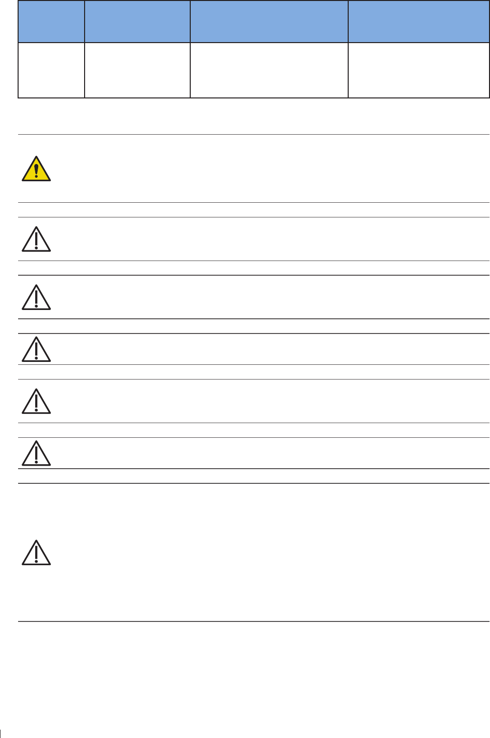
InnoSight Ultrasound System
Cleaning the System 11 einenne
122 P6992-4, EN, 16/12/6
Cleaning
solutions for
all surfaces
Cleaning solutions for
monitor screens
Disinfectants for system surfaces,
including the touch screen
Disinfectants for cart surfaces
Mild soap
solution
Mild soap solution
Cleaners designed
for touch screens
Purified water
isopropyl alcohol (IPA)
ethanol alcohol
isopropyl alcohol (IPA)
ethanol alcohol
Tale 7Disinfectants and cleaning solutions for system/system cart surfaces
If blood or other infectious material comes in contact with a transducer or transducer cable, do
not wipe with isopropyl alcohol until you have read the Chapter 1 Transducer Care section for
specific cleaning guidelines Isopropyl alcohol should not be used on some parts of the transducer
and should never be used on any parts of the transducer cable Additional cleaning agents are also
available for transducers
Do not use abrasive cleaners, or acetone, ME, paint thinner, or other strong solvents on the
system, peripherals, or transducers
Do not use Sani-Cloth AF4 or Super Sani-Cloth to disinfect the system
On display screens, do not use glass cleaners or products containing bleach Immediately wipe
away disinfectants or cleaners to prevent residue buildup
On display screens, use microfiber cloth do not use paper towels
System surfaces and transducers are resistant to ultrasound gel, alcohol, and disinfectants, but if
you use those substances, you must wipe them off to prevent permanent damage
Always use protective eyewear and gloves when cleaning and disinfecting any equipment
Attempting to disinfect a cable or connector by using a method other than the one included
here can damage the device and voids the warranty
Orient the parts that must remain dry higher than the wet parts until all parts are dry
Do not use strong solvents, common cleaning products, or abrasive cleansers, which will
damage the system surfaces
When cleaning the system surface with cleaning solutions or disinfectants, take care not to
wipe repeatedly or rub heavily on the Philips logo and model name The printing inks may start
to appear faded or stained
Do not touch the display with sharp objects or use paper towels to clean it, which may damage
it
When cleaning the system, take care not to get any solution inside the protective enclosure
Also take care not to scratch the face of the screen while cleaning it
Do not use cleaners containing bleach on the touch screen It may damage the surface

123
11 einenne Troubleshooting
InnoSight Ultrasound System
P6992-4, EN, 16/12/6
Cleaning the Power Adapter
Do not immerse the power adapter
eep moisture and liquid away from the power adapter Do not spill or spray liquid on the
adapter
1 Wipe the power adapter with a dry cloth
2 If spot cleaning is necessary, wipe with a cloth dampened with soapy water If disinfection is necessary,
wipe with an alcohol-moistened cloth
3 Remove any solid matter with a cotton swab or toothpick to ensure that solids are not pushed into the
adapter
4 Wipe off any excess moisture then leave the power adapter completely dry before plugging it into the
system or power outlet
Troubleshooting
Frequently asked questions and common problems that may occur while using the system are explained in
this section Observe the following table containing a list of symptoms and the actions to take to solve the
problems
If a problem persists after performing the following actions, contact technical support (See Customer
Service on page 3)
Symptom Possible cause and corrective action
The system does not
power on
Battery fully discharged. Connect the AC power adapter
Power adapter does not function correctly.
»Check if the power adapter has blue light illuminated
»Check if the AC plug is connected firmly and correctly to the power adapter
and matches the plug type of your country
»Check if the power adapter is connected firmly and correctly to the system
(See Charging the System on page 41)
The system can’t
charge or experience
short runtime between
charges
Power supply is damaged/battery reaches end of life.
»Allow the battery to charge overnight and check again the battery status
»Contact technical support
Unsure of a function
displayed in localized
languages
»Switch the system language back to English from Menu > Settings >
General > Language, and check again the function you want to use
»Contact technical support
The system can’t read/
write data from the
microSD card
One or two USB storage devices are connected to the system at the same
time.*
»Remove all the connected USB storage devices from the system
The microSD card is damaged.
»Insert the microSD card into a computer for inspection
»Use the diagnostic tools to test the functionality of the microSD (See Testing
the System on page 14) This requires assistance from technical support
The microSD card slot is damaged.
»Insert another microSD card into the system for inspection

InnoSight Ultrasound System
Troubleshooting 11 einenne
124 P6992-4, EN, 16/12/6
Symptom Possible cause and corrective action
The system can’t read/
write data from the USB
storage device
Two USB storage devices are connected to the system at the same time.*
»Ensure the USB storage device you wish to read/write data from is
connected to the system through the USB 3 port
The USB storage device is damaged.
»Insert the USB storage device into a computer for inspection
The USB ports are damaged.
»Insert another USB storage device into the system for inspection
No image or abnormal
display on the system
screen
The system screen is not functioning.
»Output the system display to an external monitor (See page ) and
check if images display normally on the external screen
»Contact technical support
Image Artifacts occur on
the imaging screen
Electrical interference occurs.
»Move system away from any electromagnetic sources
»Remove the power adapter and other external devices (if any) from the
system while keeping the transducer plugged for inspection
The transducer connected is damaged.
»Replace current transducer with another for inspection
»Use the diagnostic tools to test the functionality of the ultrasound engine
and the transducer (See Testing the System on page 14) This requires
assistance from technical support
Software installation
failed Check if the USB flash drives or the system’s USB ports are damaged
The system is
overheating
The system’s fans are not functioning.
»Use the diagnostic tools to test the functionality of the fan and the
temperature (See Testing the System on page 14) This requires
assistance from technical support
Ventilation slots are blocked.
»Place the system in a well-ventilated area
»Remove any dust particles or stains found on or nearby the ventilation
slots
The Power button does
not function
The system power reaches a critically low state and is not connected to power.
»Connect the system to power
»If the power button
The system encounters
unexpected shutdowns
several times
A system disk error occurred.
»Reinstall the software (See Reinstalling Software on page 13) This
requires assistance from technical support
Touch screen is
unresponsive or
misconfigured
Touch screen is damaged.
»Inspect the panel surface carefully for cracks, cuts or any other damages
Software malfunctions.
»Connect a pointing device to the system through the USB port, and check if
the pointer is displayed correctly on the screen
»Use the diagnostic tools to test the functionality of the touch screen (See
Testing the System on page 14) This requires assistance from technical
support

125
11 einenne Troubleshooting
InnoSight Ultrasound System
P6992-4, EN, 16/12/6
Symptom Possible cause and corrective action
No audio or noise
comes from the system
speakers
The system is muted.
Open the system tool menu and adjust the volume
The speakers are damaged.
»Contact technical support
HDMI does not function
The HDMI cable/port is damaged.
»Use another HDMI cable for connection
»Connect the system to a computer through HDMI connection for inspection
Bluetooth connection
failed
The Bluetooth settings are not correct.
»Turn off the Bluetooth function, then turn it back on
The Bluetooth module is not functioning.
»Connect another Bluetooth device to the system for inspection
DICOM connection
failed
The DICOM server is not responding or the DICOM settings are not correct.
»Go to Menu DICOM Storage SCP and touch Edit Test for verification
Ethernet does not
function
The Ethernet settings are not correct.
»Contact your network administrator
The Ethernet cable/socket is damaged.
»Use another Ethernet cable for connection
»Connect the system to a computer through Ethernet connection for
inspection
Wireless connection
failed
The wireless device is turned off or not functioning.
»Check the power of the wireless device
»Restart the wireless device
»Connect another wireless product to this device for inspection
The wireless network settings are not correct.
»Open the system tool menu and check if the wireless network function is
enabled
»Contact your network administrator
The system supports access to only one external storage device at a time If you connect more than
one external storage device, they function in the following priority order: USB 3 USB 2 microSD
card

InnoSight Ultrasound System
11
126 P6992-4, EN, 16/12/6

127
12 Appendix Appendix A: Specifications
12
P6992-4, EN, 16/12/6
12 Appendix
Appendix A: Specifications
Specifications are subject to change without prior notice
System
Item Specifications
Form factor Tablet
Weight 42 lb (246 kg): With the rotating stand and 4 locator pins
Dimensions
Length 12 (3196 mm)
Width 9 (2232 mm)
Height
(Thickness)
12 (31 mm): Without the rotating stand
2 (26 mm): With the rotating stand Without 4 locator pins
24 (623 mm): With the rotating stand and 4 locator pins
Materials Plastic, metal, rubber
Color White
Speaker 2 built-in speakers
Console Touch screen
Primary monitor 116 1366x6
Number of transducer
connectors 1 transducer
Stand 1 stand
Wall mount Standard VESA M4 screw when removing 4 locator pins
Holes: mm x mm/1mm x 1mm
Water resistant level IP22
CPU Qualcomm APQ4AB
User Interface Languages English, T/S Chinese, French, German, Spanish, Russian
Memory 16GB eMMC
Storage mSATA 12GB SSD support up to 12GB
Connectivity
HDMI x 1
Audio output x 1
Ethernet R4 x1
USB 2 x1
USB 3 x1
MicroSD slot x1
Transducer x1
Power Battery power/chargeable with up to 19V AC adapter
Battery Non-removable battery with 1 hour run-time

InnoSight Ultrasound System
Appendix A: Specifications 12 Appendix
12 P6992-4, EN, 16/12/6
Item Specifications
Accessories
Power adapter
Input: AC 1 24V, 6Hz, Max 1A
Output: 19Vdc, 34A
Transducer
S4-2, L12-4, C6-2, C9-4v
System cart
Support Tilt and Swivel oints, Height Adjustment, Instant dock and
undock function
Storage/transport
Temperature: -2 6C
Humidity 2 9 RH
Air pressure 16hPa
Environmental operating
conditions
Temperature: 1 4C
Humidity: 2 RH, no condensation
Air pressure: 16 hPa
Product life years
Battery
Model: QIC3
Battery type (non-removable): 3S2P Panasonic-3mAh, compliant with IEC62133 standard
Item Rate performance Remark
Battery Cell 3 mAh Panasonic
Typical capacity Above 614 mAh Rate discharge capacity after rate charge
Nominal capacity Above 33 mAh Rate discharge capacity after rate charge
Nominal voltage 1 V Mean operation voltage during rate discharge after
rate charge
Maximum charge voltage 126 V CV mode charging voltage
Voltage at end discharge 9 V Stop discharge when any cell reaches tc 2 2 V
Suggested charge current
(Standard) 12 A
Suggested charge current
(maximum) 3 A
Suggested continuous
discharge current 3 A 33 W
Suggested maximum
discharge current A W
END of charge condition 1 mA 1 min
Operating temperature
4C
1 4C
- 6C
Standard charging
In max charging
Standard discharging

129
12 Appendix Appendix A: Specifications
InnoSight Ultrasound System
P6992-4, EN, 16/12/6
Item Rate performance Remark
Storage temperature and
humidity range
-2 3C
-2 4C
-2 4C
-2 C
Within 1 year, 4 to RH
Within 6 months, 4 to RH
Within 1 month, 4 to RH
Within 1 week, 4 to RH
Power consumption
Normal mode
Sleep mode
Shutdown mode
62 A
12 A
42 A
Transducer
Transducer Elements Descriptions Applications
S4-2 64 Phased array transducer with a
maximum depth of 2 mm and a
user-controllable field-of-view
Adult abdominal
OB/GYN
Cardiac
Abdominal vascular
Fetal heart
Renal
C6-2 12 Curved array transducer with a
maximum depth of 2 mm and a
user-controllable field-of-view
Adult abdominal
OB/GYN
Fetal heart
Abdominal vascular
Renal
L12-4 12 Linear array transducer with a
maximum depth of 1 mm and a
user-controllable field-of-view
Dialysis access
Small parts
Musculoskeletal
Peripheral vascular
Medium depth arterial and
venous studies
Breast
C9-4v 12 Curved linear array transducer
with a maximum depth of 2 mm
and a user-controllable field-of-
view
OB/GYN
Fetal birth defects
Placenta previa
Cysts and fibroids
Ectopic pregnancy
Pelvic pain
Infertility
Power Adapter
Item Specifications
Brand PowerBox
Model EM 12-1
Input Universal AC 1 24V, 6Hz, Max 1A
Output 19VDC, 34A
Case Dimension 11 (L) x (W) x 4 (H) mm without AC plugs

InnoSight Ultrasound System
Appendix B: Connectivity and Security 12 Appendix
13 P6992-4, EN, 16/12/6
Item Specifications
Water resistant level IP21
Efficiency Eff (av)
Safety Approved according to IEC 661-1 Edition 3
EMC IEC 661-1-2, IEC 6124-3, EN 11 Class B
Protection OVP (Over Voltage Protection), SCP (Short Circuit Protection), OCP (Over
Current Protection)
Features
Highest output power on the market of wall plug adapters
Exchangeable AC-plugs for universal use
Suitable to power up medical systems up to BF class
Appendix B: Connectivity and Security
Introduction
To exchange ultrasound images and patient data, the system conforms with the Digital Imaging and
Communications in Medicine (DICOM) standard and can therefore be connected to Picture Archiving
and Communication System (PACS) and Modality Worklist (MWL) The former allows the system to store
the acquired examination data (static images or image loops) in PACS, while the latter allows the system
to query examination orders from the MWL server and start the examinations In order to achieve the
purposes above, the system offers two ways of connecting to the IT network, hard-wired LAN and wireless
LAN connections, for DICOM communication
To ensure the data security, use an IT network isolated from the external environment by a
firewall
Specifications
Hardware
211 a/b/g/n, Gigabit Ethernet
Software
The system is connected to PACS and MWL by DICOM standard
Read the system’s DICOM Conformance Statement for detailed instructions
Security
The system has no listening ports open to the WLAN interface So a network entity cannot initiate a
connection to the system from the WLAN However, the system can initiate a connection to servers on the
WLAN, Gigabit Ethernet and beyond Computer access to the system through the USB port is blocked
The system allows connection via Bluetooth with limited devices (HID) only
Use the following TCP/IP ports for outgoing communication to the WLAN and Gigabit Ethernet
131
12 Appendix Appendix B: Connectivity and Security
InnoSight Ultrasound System
P6992-4, EN, 16/12/6
Port for DICOM communication (typically port 14, 262 or 11112 to specify the port, on the
system’s imaging screen, touch Menu >Settings > DICOM
Port for HTTP web servers (not supported by the system)
Anti-virus software is not installed on the system
Information Flow
InnoSight
Worklist
server
PACS
server
Worklist query
Worklist response
DICOM storage/Echo request
Echo response
Figure 43Information flow
Read the system’s DICOM Conformance Statement for detailed instructions DICOM conformance
statements for Philips products are available at this website:
wwwhealthcarephilipscom/main/about/connectivity/dicomconformancemainwpd
IT Network Failure Recovery Measures
IT network connection stability depends on many factors Unreliable connection may later lead to failure
and cause the following hazardous situations
Any connection of the equipment, this system (InnoSight) or/and other systems, to the IT network risks the
unidentified data leakage of the patients, operators or third parties It is recommended to set up the device
in a secure network and behind the firewall The potential risks and suitable countermeasures are evaluated
and identified in the following table before connecting the equipment to an uncontrolled IT network
Therefore, you must evaluate and identify all potential risks as well as prepare suitable countermeasures
before connecting the equipment to an uncontrolled IT network For guidance addressing these risks, refer
to IEC 1-1:21

InnoSight Ultrasound System
Appendix B: Connectivity and Security 12 Appendix
132 P6992-4, EN, 16/12/6
IT Network
failure Impact on the equipment Hazard System countermeasures
IT network
becomes
unstable
Unable to transmit exam
data to a PACS Delay of
diagnosis
Exam data is stored in the system’s internal
storage After the IT network has resumed
stability, you can re-initiate the data transfer
Delay of transmission to a
PACS
Incorrect data
transmitted to a PACS Mis-diagnosis The system uses the TCP/IP and DICOM
protocols to ensure the integrity of the data
Unable to retrieve order
data from an MWL server Delay of exam You can initiate/create a new exam from the
system
Delay of retrieving order
data from an MWL server
Incorrect data from a
MWL server Incorrect exam The system uses the TCP/IP and DICOM
protocols to ensure the integrity of the data
Firewall has
broken down
Attack via network Manipulation of
the exam data
The system closes unnecessary network
ports
Infection by computer
virus
Exam data
leakage
The system forbids installation of any
software by any user
Tale 8IT network failure recovery measures
Even when the connection to an IT network is trusted, any change of the network settings requires
immediate checkup and possible measures taken Should any of the changes below occur, perform
additional evaluation to the IT network
Changes in the network configuration (IP address, router, proxy, and so on)
Connection of additional items
Disconnection of items
Equipment update
Equipment upgrade

133
12 Appendix Appendix C: System Acoustic Output Default Tables
InnoSight Ultrasound System
P6992-4, EN, 16/12/6
Appendix C: System Acoustic Output Default Tables
C6-2 Transducer
Exam Type Preset Mode TI Label Default TI Default MI
Abdominal Abdomen
2D
Color
CPA
M
PW
THIColor
THICPA
THIM
2DColorPW (Triplex)
2DCPAPW (Triplex)
Fetal OB
2D
Color
CPA
M
PW
THIColor
THICPA
THIM
2DColorPW (Triplex)
2DCPAPW (Triplex)

InnoSight Ultrasound System
Appendix C: System Acoustic Output Default Tables 12 Appendix
134 P6992-4, EN, 16/12/6
Exam Type Preset Mode TI Label Default TI Default MI
Urology
Renal
2D
Color
CPA
M
PW
THIColor
THICPA
THIM
2DColorPW (Triplex)
2DCPAPW (Triplex)
Urology
2D
Color
CPA
M
PW
THIColor
THICPA
THIM
2DColorPW (Triplex)
2DCPAPW (Triplex)
GYN GYN
2D
Color
CPA
M
PW
THIColor
THICPA
THIM
2DColorPW (Triplex)
2DCPAPW (Triplex)

13
12 Appendix Appendix C: System Acoustic Output Default Tables
InnoSight Ultrasound System
P6992-4, EN, 16/12/6
L12-4 Transducer
Exam Type Preset Mode TI Label Default TI Default MI
Cardiac Vascular
Carotid
2D
Color
CPA
M
PW
THIColor
THICPA
THIM
2DColorPW (Triplex)
2DCPAPW (Triplex)
Arterial
2D
Color
CPA
M
PW
THIColor
THICPA
THIM
2DColorPW (Triplex)
2DCPAPW (Triplex)
Venous
2D
Color
CPA
M
PW
THIColor
THICPA
THIM
2DColorPW (Triplex)
2DCPAPW (Triplex)

InnoSight Ultrasound System
Appendix C: System Acoustic Output Default Tables 12 Appendix
136 P6992-4, EN, 16/12/6
Exam Type Preset Mode TI Label Default TI Default MI
Small Organ
(breast, thyroid)
Thyroid
2D
Color
CPA
M
PW
THIColor
THICPA
THIM
2DColorPW (Triplex)
2DCPAPW (Triplex)
Breast
2D
Color
CPA
M
PW
THIColor
THICPA
THIM
2DColorPW (Triplex)
2DCPAPW (Triplex)
Abdominal Bowel
2D
Color
CPA
M
PW
THIColor
THICPA
THIM
2DColorPW (Triplex)
2DCPAPW (Triplex)
Muscle MS
2D
Color
CPA
M
PW
THIColor
THICPA
THIM
2DColorPW (Triplex)
2DCPAPW (Triplex)

13
12 Appendix Appendix C: System Acoustic Output Default Tables
InnoSight Ultrasound System
P6992-4, EN, 16/12/6
Exam Type Preset Mode TI Label Default TI Default MI
Nerve Nerve
2D
Color
CPA
M
PW
THIColor
THICPA
THIM
2DColorPW (Triplex)
2DCPAPW (Triplex)
S4-2 Transducer
Exam Type Preset Mode TI Label Default TI Default MI
Cardiac Cardiac
2D
Color
CPA
M
PW
THIColor
THICPA
THIM
2DColorPW (Triplex)
2DCPAPW (Triplex)

InnoSight Ultrasound System
Appendix C: System Acoustic Output Default Tables 12 Appendix
13 P6992-4, EN, 16/12/6
C9-4v Transducer
Exam Type Preset Mode TI Label Default TI Default MI
Trans-vaginal
Cardiac
OB
2D
Color
CPA
M
PW
THIColor
THICPA
THIM
2DColorPW (Triplex)
2DCPAPW (Triplex)
GYN
2D
Color
CPA
M
PW
THIColor
THICPA
THIM
2DColorPW (Triplex)
2DCPAPW (Triplex)
Trans-rectal Prostate
2D
Color
CPA
M
PW
THIColor
THICPA
THIM
2DColorPW (Triplex)
2DCPAPW (Triplex)

139
12 Appendix Appendix D: Acoustic Output Reporting Tables for Track 3
InnoSight Ultrasound System
P6992-4, EN, 16/12/6
Appendix D: Acoustic Output Reporting Tables for Track 3
We follow Track 3 of the FDA’s information for manufacturers seeking marketing clearance of diagnostic
ultrasound systems and transducers All table entries have been obtained at the same operating conditions
that give rise to the maximum index value Due to the complexities of the system user interface, it may be
difficult to exactly replicate the declared condition For more information, contact Philips
Definition of Terms Used in Acoustic Output Tables
Symbols used in the tables are described below:
: Acoustic attenuation coefficient is the coefficient intended to account for ultrasonic attenuation of tissue
between the source and a specified point
Aaprt: -12 dB output beam area is the area of the ultrasonic beam derived from the -12 dB output beam
dimensions
CMI: Normalizing coefficient 1 MPa MHz-1/2
Deq: Equivalent aperture diameter is the diameter of a circle whose area is the -12dB output beam area and
given by Deq Aaprt
4
d-6: Pulse beam width is the distance between two points, on a specified surface in a specified direction,
passing through the point of maximum pulse-pressure-squared integral (pi) in that surface, at which the
pulse-pressure-squared integral is a specified fraction of the maximum value in that surface
deq: Equivalent beam diameter is the value of the diameter of the acoustic beam at the distance z, in terms
of the equivalent beam area, and given by deq(z) Aeq(z)
4
fawf: Acoustic working frequency is the arithmetic mean of the most widely separated frequencies f1 and f2 at
which the amplitude of the pressure spectrum of the acoustic signal is 3 dB lower than the peak amplitude
Ipa: Pulse-average intensity is the ratio of the pulse-intensity integral Ipi to the pulse duration td
Ipa, : Attenuated pulse-average intensity is the value of the acoustic pulse-average intensity after
attenuation and at a specified point and given by Ipa, Ipa(z)1(awf/1)
Ipi: Pulse-intensity integral is the time integral of the instantaneous intensity at a particular point in an
acoustic field integrated over the acoustic pulse waveform
Ipi, : Attenuated pulse-intensity integral is the value of the pulse-intensity integral after attenuation, at a
specified point, and given by Ipi, Ipi10(awf/1)
Isppa, : Attenuated spatial-peak pulse-average intensity
Ispta: Spatial-peak temporal-average intensity
Ispta, : Attenuated spatial-peak temporal-average intensity
Ita(z): Temporal-average intensity is the time-average of the instantaneous intensity at a particular point in
an acoustic field
Ita, (z): Attenuated temporal-average intensity is the value of the temporal-average intensity after
attenuation, at a specified point, and given by Ita, (z) Ita(z)1(awf/1)
Izpta(z): Spatial-peak temporal-average intensity is the maximum value of the temporal-average intensity in a
specified plane at a specified distance z from the transducer
Izpta, (z): Attenuated spatial-peak temporal-average intensity is the value of the spatial-peak temporal-
average intensity after attenuation, at a specified distance z, and given by Izpta, (z) Izpta(z)1(awf/1)
MI: Mechanical index is given by MI CMI
Prafawf
-1/2
npps: Number of pulses per ultrasonic scan line

InnoSight Ultrasound System
Appendix D: Acoustic Output Reporting Tables for Track 3 12 Appendix
140 P6992-4, EN, 16/12/6
P: Output power is the time-average power radiated by an ultrasonic transducer into an approximately free
field under specified conditions in a specified medium, preferably water
P: Attenuated output power is the value of the acoustic output power after attenuation, at a specified
distance from the transducer, and given by p p10(awf/1)
pi: Pulse-pressure-squared integral is the time integral of the square of the instantaneous acoustic pressure
at a particular point in an acoustic field integrated over the acoustic pulse waveform
pii: Pulse-intensity integral
pii: Attenuated Pulse-intensity integral
pr: Peak-rarefactional acoustic pressure is the maximum of the modulus of the negative instantaneous
acoustic pressure in an acoustic field during an acoustic repetition period
pr, : Attenuated peak-rarefactional acoustic pressure is the value of the peak-rarefactional acoustic pressure
after attenuation, at a specified point, and given by pr, (z) pr(z)1(awf/2)
prr: Pulse repetition rate is the inverse of the time interval between two successive acoustic pulses
srr: Scan repetition rate
TI: Thermal index is the ratio of attenuated acoustic power at a specified point to the attenuated acoustic
power required to raise the temperature at that point in a specific tissue model by 1C
TIB: Bone thermal index is the thermal index for applications, such as fetal (second and third trimester) or
neonatal cephalic (through the fontanelle), in which the ultrasound beam passes through soft tissue, and a
focal region is in the immediate vicinity of bone
TIC: Cranial-bone thermal index is the thermal index for applications, such as pediatric and adult-cranial
applications, in which the ultrasound beam passes through bone near the beam entrance into the body
TIS: Soft-tissue thermal index is the thermal index related to soft tissues
td: Pulse duration is 12 times the interval between the time when the time integral of intensity in an
acoustic pulse at a point reaches 1 and when it reaches 9 of the pulse-intensity integral
X, Y: -12 dB output beam dimensions are dimensions of the ultrasonic beam (-12dB pulse beam width) in
specified directions normal to the beam alignment axis and at the transducer output face
z: Distance from the source to a specified point
zb: Depth for TIB
zbp: Break-point depth is the value equal to 1 times the equivalent aperture diameter and given by zbp
1Deq
zpii: Depth for peak pulse-intensity integral
zMI: Depth for MI
zpii, : Depth for peak attenuated pulse-intensity integral
zsii: Depth for peak sum of pulse-intensity integrals
zsii, : Depth for peak sum of attenuated pulse-intensity integrals
zs: Depth for TIS

141
12 Appendix Appendix D: Acoustic Output Reporting Tables for Track 3
InnoSight Ultrasound System
P6992-4, EN, 16/12/6
Acoustic Output Tables for InnoSight Transducers
Acoustic Output Reporting Table for Track 3 for the C6-2 Transducer
InnoSight Diagnostic Ultrasound System in 2D Mode
Index label MI
TIS
TIB TIC
Scan Non-scan
Aaprt 1cm2Aaprt > 1cm2
Global maximum index value 119 # # # (b)
Associated
acoustic
parameter
Pr3 (MPa) 21
W0(mW) 21 # # #
Min of W3(z1),
ITA3(z1) (mW) #
z1(cm) #
zbp (cm) #
zsp (cm) #
zPII3max (cm) 4
deq(zsp) (cm) #
fc(MHz) 3 3 # # # #
Dim of Aaprt
(cm) 2 # # # #
Y (cm) 13 # # # #
Other
information
PD (microsec) 4
PRF (Hz) 5900
prPIImax (MPa) 36
deqPIImax (cm) #
Focal length FLx (cm) 5 # # #
FLy (cm) # # #
Ipa3 MImax (W/cm2) 211
Operating
control
conditions
Control 1 2D 2D # # # #
Control 2 5 5 # # # #
Control 3 2 2 # # # #
Control 4 100 100 # # # #
No data are reported for this operating condition since the global maximum index value
is not reported for the reason listed
(a) This index is not required for this operating mode
(b) This transducer is not intended for transcranial or neonatal cephalic uses
(c) This formulation for TIS is less than that for an alternate formulation in this mode
(d) Control 1: Mode
(e) Control 2: Focal distance (cm)
(f) Control 3: PRF (Hz)
(g) Control 4: Power ()

InnoSight Ultrasound System
Appendix D: Acoustic Output Reporting Tables for Track 3 12 Appendix
142 P6992-4, EN, 16/12/6
Acoustic Output Reporting Table for Track 3 for the C6-2 Transducer
InnoSight Diagnostic Ultrasound System in THI Mode
Index label MI
TIS
TIB TIC
Scan Non-scan
Aaprt 1cm2Aaprt > 1cm2
Global maximum index value 14 16 # # # (b)
Associated
acoustic
parameter
Pr3 (MPa) 24
W0(mW) 3 # # #
Min of W3(z1),
ITA3(z1) (mW) #
z1(cm) #
zbp (cm) #
zsp (cm) #
zPII3max (cm) 5
deq(zsp) (cm) #
fc(MHz) 29 29 # # # #
Dim of Aaprt
(cm) 2 # # # #
Y (cm) 13 # # # #
Other
information
PD (microsec) 1
PRF (Hz) 5900
prPIImax (MPa) 39
deqPIImax (cm) #
Focal length FLx (cm) 5 # # #
FLy (cm) # # #
Ipa3 MImax (W/cm2) 32
Operating
control
conditions
Control 1 THI THI # # # #
Control 2 5 5 # # # #
Control 3 2 2 # # # #
Control 4 100 100 # # # #
No data are reported for this operating condition since the global maximum index value
is not reported for the reason listed
(a) This index is not required for this operating mode
(b) This transducer is not intended for transcranial or neonatal cephalic uses
(c) This formulation for TIS is less than that for an alternate formulation in this mode
(d) Control 1: Mode
(e) Control 2: Focal distance (cm)
(f) Control 3: PRF (Hz)
(g) Control 4: Power ()

143
12 Appendix Appendix D: Acoustic Output Reporting Tables for Track 3
InnoSight Ultrasound System
P6992-4, EN, 16/12/6
Acoustic Output Reporting Table for Track 3 for the C6-2 Transducer
InnoSight Diagnostic Ultrasound System in 2D+Color Mode
Index label MI
TIS
TIB TIC
Scan Non-scan
Aaprt 1cm2Aaprt > 1cm2
Global maximum index value 11 13 # # # (b)
Associated
acoustic
parameter
Pr3 (MPa) 2
W0(mW) 70 # # #
Min of W3(z1),
ITA3(z1) (mW) #
z1(cm) #
zbp (cm) #
zsp (cm) #
zPII3max (cm) 4
deq(zsp) (cm) #
fc(MHz) 249 249 # # # #
Dim of Aaprt
(cm) 22 # # # #
Y (cm) 13 # # # #
Other
information
PD (microsec) 142
PRF (Hz) 5000
prPIImax (MPa) 3
deqPIImax (cm) #
Focal length FLx (cm) 5 # # #
FLy (cm) # # #
Ipa3 MImax (W/cm2) 41
Operating
control
conditions
Control 1 Color 2D
Color # # # #
Control 2 5 5 # # # #
Control 3 5000 5000 # # # #
Control 4 100 100 # # # #
No data are reported for this operating condition since the global maximum index value
is not reported for the reason listed
(a) This index is not required for this operating mode
(b) This transducer is not intended for transcranial or neonatal cephalic uses
(c) This formulation for TIS is less than that for an alternate formulation in this mode
(d) Control 1: Mode
(e) Control 2: Focal distance (cm)
(f) Control 3: PRF (Hz)
(g) Control 4: Power ()

InnoSight Ultrasound System
Appendix D: Acoustic Output Reporting Tables for Track 3 12 Appendix
144 P6992-4, EN, 16/12/6
Acoustic Output Reporting Table for Track 3 for the C6-2 Transducer
InnoSight Diagnostic Ultrasound System in THI+Color Mode
Index label MI
TIS
TIB TIC
Scan Non-scan
Aaprt 1cm2Aaprt > 1cm2
Global maximum index value 12 166 # # # (b)
Associated
acoustic
parameter
Pr3 (MPa) 22
W0(mW) 95 # # #
Min of W3(z1),
ITA3(z1) (mW) #
z1(cm) #
zbp (cm) #
zsp (cm) #
zPII3max (cm) 4
deq(zsp) (cm) #
fc(MHz) 249 249 # # # #
Dim of Aaprt
(cm) 22 # # # #
Y (cm) 13 # # # #
Other
information
PD (microsec) 142
PRF (Hz) 5000
prPIImax (MPa) 4
deqPIImax (cm) #
Focal length FLx (cm) 5 # # #
FLy (cm) # # #
Ipa3 MImax (W/cm2) 44
Operating
control
conditions
Control 1 Color THI
Color # # # #
Control 2 5 5 # # # #
Control 3 5000 5000 # # # #
Control 4 100 100 # # # #
No data are reported for this operating condition since the global maximum index value
is not reported for the reason listed
(a) This index is not required for this operating mode
(b) This transducer is not intended for transcranial or neonatal cephalic uses
(c) This formulation for TIS is less than that for an alternate formulation in this mode
(d) Control 1: Mode
(e) Control 2: Focal distance (cm)
(f) Control 3: PRF (Hz)
(g) Control 4: Power ()

145
12 Appendix Appendix D: Acoustic Output Reporting Tables for Track 3
InnoSight Ultrasound System
P6992-4, EN, 16/12/6
Acoustic Output Reporting Table for Track 3 for the C6-2 Transducer
InnoSight Diagnostic Ultrasound System in 2D+M-Mode
Index label MI
TIS
TIB TIC
Scan Non-scan
Aaprt 1cm2Aaprt > 1cm2
Global maximum index value 14 # # 64 34 (b)
Associated
acoustic
parameter
Pr3 (MPa) 2
W0(mW) # # 2 #
Min of W3(z1),
ITA3(z1) (mW) 4
z1(cm) 6
zbp (cm) 29
zsp (cm)
zPII3max (cm) 6
deq(zsp) (cm) 43
fc(MHz) 31 # # 31 31 #
Dim of Aaprt
(cm) # # 22 22 #
Y (cm) # # 13 13 #
Other
information
PD (microsec) 41
PRF (Hz) 250
prPIImax (MPa) 46
deqPIImax (cm) 42
Focal length FLx (cm) # # 6 #
FLy (cm) # # #
Ipa3 MImax (W/cm2) 32
Operating
control
conditions
Control 1 M-Mode # # M-Mode M-Mode #
Control 2 6 # # 6 6 #
Control 3 250 # # 250 250 #
Control 4 100 # # 100 100 #
No data are reported for this operating condition since the global maximum index value
is not reported for the reason listed
(a) This index is not required for this operating mode
(b) This transducer is not intended for transcranial or neonatal cephalic uses
(c) This formulation for TIS is less than that for an alternate formulation in this mode
(d) Control 1: Mode
(e) Control 2: Focal distance (cm)
(f) Control 3: PRF (Hz)
(g) Control 4: Power ()

InnoSight Ultrasound System
Appendix D: Acoustic Output Reporting Tables for Track 3 12 Appendix
146 P6992-4, EN, 16/12/6
Acoustic Output Reporting Table for Track 3 for the C6-2 Transducer
InnoSight Diagnostic Ultrasound System in THI+M-Mode
Index label MI
TIS
TIB TIC
Scan Non-scan
Aaprt 1cm2Aaprt > 1cm2
Global maximum index value 14 # # 64 (b)
Associated
acoustic
parameter
Pr3 (MPa) 22
W0(mW) # # 54 #
Min of W3(z1),
ITA3(z1) (mW) 4
z1(cm)
zbp (cm) 29
zsp (cm)
zPII3max (cm)
deq(zsp) (cm) 69
fc(MHz) 31 # # 31 31 #
Dim of Aaprt
(cm) # # 22 22 #
Y (cm) # # 13 13 #
Other
information
PD (microsec) 41
PRF (Hz) 250
prPIImax (MPa) 4
deqPIImax (cm) 6
Focal length FLx (cm) # # 6 #
FLy (cm) # # #
Ipa3 MImax (W/cm2) 292
Operating
control
conditions
Control 1 THIM-
Mode # # THIM-
Mode
THIM-
Mode #
Control 2 6 # # 6 6 #
Control 3 250 # # 250 250 #
Control 4 100 # # 100 100 #
No data are reported for this operating condition since the global maximum index value
is not reported for the reason listed
(a) This index is not required for this operating mode
(b) This transducer is not intended for transcranial or neonatal cephalic uses
(c) This formulation for TIS is less than that for an alternate formulation in this mode
(d) Control 1: Mode
(e) Control 2: Focal distance (cm)
(f) Control 3: PRF (Hz)
(g) Control 4: Power ()

147
12 Appendix Appendix D: Acoustic Output Reporting Tables for Track 3
InnoSight Ultrasound System
P6992-4, EN, 16/12/6
Acoustic Output Reporting Table for Track 3 for the C6-2 Transducer
InnoSight Diagnostic Ultrasound System in PW Doppler Mode
Index label MI
TIS
TIB TIC
Scan Non-scan
Aaprt 1cm2Aaprt > 1cm2
Global maximum index value 26 # # 132 33 (b)
Associated
acoustic
parameter
Pr3 (MPa) 33
W0(mW) # # 52 #
Min of W3(z1),
ITA3(z1) (mW) 111
z1(cm) 4
zbp (cm) 3
zsp (cm) 43
zPII3max (cm) 4
deq(zsp) (cm) 16
fc(MHz) 2 # # 2 2 #
Dim of Aaprt
(cm) # # 2 2 #
Y (cm) # # 13 13 #
Other
information
PD (microsec) 1
PRF (Hz) 13
prPIImax (MPa) 4
deqPIImax (cm) 163
Focal length FLx (cm) # # 5 #
FLy (cm) # # #
Ipa3 MImax (W/cm2) 9
Operating
control
conditions
Control 1 PW # # PW PW #
Control 2 5 # # 5 5 #
Control 3 13 # # 13 13 #
Control 4 100 # # 100 100 #
No data are reported for this operating condition since the global maximum index value
is not reported for the reason listed
(a) This index is not required for this operating mode
(b) This transducer is not intended for transcranial or neonatal cephalic uses
(c) This formulation for TIS is less than that for an alternate formulation in this mode
(d) Control 1: Mode
(e) Control 2: Focal distance (cm)
(f) Control 3: PRF (Hz)
(g) Control 4: Power ()

InnoSight Ultrasound System
Appendix D: Acoustic Output Reporting Tables for Track 3 12 Appendix
14 P6992-4, EN, 16/12/6
Acoustic Output Reporting table for Track 3 for the L12-4 Transducer
InnoSight Diagnostic Ultrasound System in 2D Mode
Index label MI
TIS
TIB TIC
Scan Non-scan
Aaprt 1cm2Aaprt > 1cm2
Global maximum index value 11 # # # (b)
Associated
acoustic
parameter
Pr3 (MPa) 299
W0(mW) # # #
Min of W3(z1),
ITA3(z1) (mW) #
z1(cm) #
zbp (cm) #
zsp (cm) #
zPII3max (cm) 149
deq(zsp) (cm) #
fc(MHz) 66 66 # # # #
Dim of Aaprt
(cm) 6 # # # #
Y (cm) 4 # # # #
Other
information
PD (microsec) 194
PRF (Hz) 13
prPIImax (MPa) 4
deqPIImax (cm) #
Focal length FLx (cm) 2 # # #
FLy (cm) 19 # # #
Ipa3 MImax (W/cm2) 46
Operating
control
conditions
Control 1 2D 2D # # # #
Control 2 2 2 # # # #
Control 3 13661 13661 # # # #
Control 4 100 100 # # # #
No data are reported for this operating condition since the global maximum index value
is not reported for the reason listed
(a) This index is not required for this operating mode
(b) This transducer is not intended for transcranial or neonatal cephalic uses
(c) This formulation for TIS is less than that for an alternate formulation in this mode
(d) Control 1: Mode
(e) Control 2: Focal distance (cm)
(f) Control 3: PRF (Hz)
(g) Control 4: Power ()

149
12 Appendix Appendix D: Acoustic Output Reporting Tables for Track 3
InnoSight Ultrasound System
P6992-4, EN, 16/12/6
Acoustic Output Reporting Table for Track 3 for the L12-4 Transducer
InnoSight Diagnostic Ultrasound System in THI Mode
Index label MI
TIS
TIB TIC
Scan Non-scan
Aaprt 1cm2Aaprt > 1cm2
Global maximum index value 121 13 # # # (b)
Associated
acoustic
parameter
Pr3 (MPa) 33
W0(mW) 6 # # #
Min of W3(z1),
ITA3(z1) (mW) #
z1(cm) #
zbp (cm) #
zsp (cm) #
zPII3max (cm) 146
deq(zsp) (cm) #
fc(MHz) 3 3 # # # #
Dim of Aaprt
(cm) 6 # # # #
Y (cm) 4 # # # #
Other
information
PD (microsec) 34
PRF (Hz) 13
prPIImax (MPa) 46
deqPIImax (cm) #
Focal length FLx (cm) 2 # # #
FLy (cm) 19 # # #
Ipa3 MImax (W/cm2) 2
Operating
control
conditions
Control 1 THI THI # # # #
Control 2 2 2 # # # #
Control 3 13661 13661 # # # #
Control 4 100 100 # # # #
No data are reported for this operating condition since the global maximum index value
is not reported for the reason listed
(a) This index is not required for this operating mode
(b) This transducer is not intended for transcranial or neonatal cephalic uses
(c) This formulation for TIS is less than that for an alternate formulation in this mode
(d) Control 1: Mode
(e) Control 2: Focal distance (cm)
(f) Control 3: PRF (Hz)
(g) Control 4: Power ()

InnoSight Ultrasound System
Appendix D: Acoustic Output Reporting Tables for Track 3 12 Appendix
150 P6992-4, EN, 16/12/6
Acoustic Output Reporting Table for Track 3 for the L12-4 Transducer
InnoSight Diagnostic Ultrasound System in 2D+Color Mode
Index label MI
TIS
TIB TIC
Scan Non-scan
Aaprt 1cm2Aaprt > 1cm2
Global maximum index value 13 22 # # # (b)
Associated
acoustic
parameter
Pr3 (MPa) 231
W0(mW) 39 # # #
Min of W3(z1),
ITA3(z1) (mW) #
z1(cm) #
zbp (cm) #
zsp (cm) #
zPII3max (cm) 21
deq(zsp) (cm) #
fc(MHz) 5 5 # # # #
Dim of Aaprt
(cm) 3 # # # #
Y (cm) 4 # # # #
Other
information
PD (microsec) 9
PRF (Hz) 3
prPIImax (MPa) 33
deqPIImax (cm) #
Focal length FLx (cm) 2 # # #
FLy (cm) 19 # # #
Ipa3 MImax (W/cm2) 3
Operating
control
conditions
Control 1 Color 2DColor # # # #
Control 2 2 2 # # # #
Control 3 3 3 # # # #
Control 4 100 100 # # # #
No data are reported for this operating condition since the global maximum index value
is not reported for the reason listed
(a) This index is not required for this operating mode
(b) This transducer is not intended for transcranial or neonatal cephalic uses
(c) This formulation for TIS is less than that for an alternate formulation in this mode
(d) Control 1: Mode
(e) Control 2: Focal distance (cm)
(f) Control 3: PRF (Hz)
(g) Control 4: Power ()

151
12 Appendix Appendix D: Acoustic Output Reporting Tables for Track 3
InnoSight Ultrasound System
P6992-4, EN, 16/12/6
Acoustic Output Reporting Table for Track 3 for the L12-4 Transducer
InnoSight Diagnostic Ultrasound System in THI+Color Mode
Index label MI
TIS
TIB TIC
Scan Non-scan
Aaprt 1cm2Aaprt > 1cm2
Global maximum index value 11 241 # # # (b)
Associated
acoustic
parameter
Pr3 (MPa) 226
W0(mW) 39 # # #
Min of W3(z1),
ITA3(z1) (mW) #
z1(cm) #
zbp (cm) #
zsp (cm) #
zPII3max (cm) 21
deq(zsp) (cm) #
fc(MHz) 5 5 # # # #
Dim of Aaprt
(cm) 3 # # # #
Y (cm) 4 # # # #
Other
information
PD (microsec) 9
PRF (Hz) 2500
prPIImax (MPa) 33
deqPIImax (cm) #
Focal length FLx (cm) 2 # # #
FLy (cm) 19 # # #
Ipa3 MImax (W/cm2) 4
Operating
control
conditions
Control 1 Color THIColor # # # #
Control 2 2 2 # # # #
Control 3 2500 2500 # # # #
Control 4 100 100 # # # #
No data are reported for this operating condition since the global maximum index value
is not reported for the reason listed
(a) This index is not required for this operating mode
(b) This transducer is not intended for transcranial or neonatal cephalic uses
(c) This formulation for TIS is less than that for an alternate formulation in this mode
(d) Control 1: Mode
(e) Control 2: Focal distance (cm)
(f) Control 3: PRF (Hz)
(g) Control 4: Power ()

InnoSight Ultrasound System
Appendix D: Acoustic Output Reporting Tables for Track 3 12 Appendix
152 P6992-4, EN, 16/12/6
Acoustic Output Reporting Table for Track 3 for the L12-4 Transducer
InnoSight Diagnostic Ultrasound System in 2D+M-Mode
Index label MI
TIS
TIB TIC
Scan Non-scan
Aaprt 1cm2Aaprt > 1cm2
Global maximum index value 166 #126 #21 (b)
Associated
acoustic
parameter
Pr3 (MPa) 42
W0(mW) #41 41 #
Min of W3(z1),
ITA3(z1) (mW) #
z1(cm) #
zbp (cm) #
zsp (cm) 136
zPII3max (cm) 144
deq(zsp) (cm) 196
fc(MHz) 6 #6 #6 #
Dim of Aaprt
(cm) #1 #1 #
Y (cm) #4 #4 #
Other
information
PD (microsec) 2
PRF (Hz) 250
prPIImax (MPa)
deqPIImax (cm) 196
Focal length FLx (cm) # 2 # #
FLy (cm) #19 # #
Ipa3 MImax (W/cm2) 14
Operating
control
conditions
Control 1 M-Mode #M-Mode #M-Mode #
Control 2 2 # 2 # 2 #
Control 3 250 # 250 # 250 #
Control 4 100 # 100 # 100 #
No data are reported for this operating condition since the global maximum index value
is not reported for the reason listed
(a) This index is not required for this operating mode
(b) This transducer is not intended for transcranial or neonatal cephalic uses
(c) This formulation for TIS is less than that for an alternate formulation in this mode
(d) Control 1: Mode
(e) Control 2: Focal distance (cm)
(f) Control 3: PRF (Hz)
(g) Control 4: Power ()

13
12 Appendix Appendix D: Acoustic Output Reporting Tables for Track 3
InnoSight Ultrasound System
P6992-4, EN, 16/12/6
Acoustic Output Reporting Table for Track 3 for the L12-4 Transducer
InnoSight Diagnostic Ultrasound System in THI+M-Mode
Index label MI
TIS
TIB TIC
Scan Non-scan
Aaprt 1cm2Aaprt > 1cm2
Global maximum index value 16 #231 #312 (b)
Associated
acoustic
parameter
Pr3 (MPa) 4
W0(mW) # #
Min of W3(z1),
ITA3(z1) (mW) #
z1(cm) #
zbp (cm) #
zsp (cm) 14
zPII3max (cm) 146
deq(zsp) (cm) 24
fc(MHz) 6 #6 #6 #
Dim of Aaprt
(cm) #1 #1 #
Y (cm) #4 #4 #
Other
information
PD (microsec) 199
PRF (Hz) 250
prPIImax (MPa) 3
deqPIImax (cm) 24
Focal length FLx (cm) # 2 # #
FLy (cm) #19 # #
Ipa3 MImax (W/cm2) 96
Operating
control
conditions
Control 1 M-Mode #M-Mode #M-Mode #
Control 2 2 # 2 # 2 #
Control 3 250 # 250 # 250 #
Control 4 100 # 100 # 100 #
No data are reported for this operating condition since the global maximum index value
is not reported for the reason listed
(a) This index is not required for this operating mode
(b) This transducer is not intended for transcranial or neonatal cephalic uses
(c) This formulation for TIS is less than that for an alternate formulation in this mode
(d) Control 1: Mode
(e) Control 2: Focal distance (cm)
(f) Control 3: PRF (Hz)
(g) Control 4: Power ()

InnoSight Ultrasound System
Appendix D: Acoustic Output Reporting Tables for Track 3 12 Appendix
154 P6992-4, EN, 16/12/6
Acoustic Output Reporting Table for Track 3 for the L12-4 Transducer
InnoSight Diagnostic Ultrasound System in PW Doppler Mode
Index label MI
TIS
TIB TIC
Scan Non-scan
Aaprt 1cm2Aaprt > 1cm2
Global maximum index value 1 #4 #36 (b)
Associated
acoustic
parameter
Pr3 (MPa) 3
W0(mW) #16 16 #
Min of W3(z1),
ITA3(z1) (mW) #
z1(cm) #
zbp (cm) #
zsp (cm) 12
zPII3max (cm) 133
deq(zsp) (cm) 6
fc(MHz) 5 # 5 # 5 #
Dim of Aaprt
(cm) #41 #41 #
Y (cm) #4 #4 #
Other
information
PD (microsec) 9
PRF (Hz) 5000
prPIImax (MPa) 4
deqPIImax (cm) 6
Focal length FLx (cm) # 2 # #
FLy (cm) #19 # #
Ipa3 MImax (W/cm2) 9
Operating
control
conditions
Control 1 PW
Doppler #PW Doppler #PW
Doppler #
Control 2 2 # 2 # 2 #
Control 3 5000 # 5000 # 5000 #
Control 4 100 # 100 # 100 #
No data are reported for this operating condition since the global maximum index value
is not reported for the reason listed
(a) This index is not required for this operating mode
(b) This transducer is not intended for transcranial or neonatal cephalic uses
(c) This formulation for TIS is less than that for an alternate formulation in this mode
(d) Control 1: Mode
(e) Control 2: Focal distance (cm)
(f) Control 3: PRF (Hz)
(g) Control 4: Power ()

155
12 Appendix Appendix D: Acoustic Output Reporting Tables for Track 3
InnoSight Ultrasound System
P6992-4, EN, 16/12/6
Acoustic Output Reporting Table for Track 3 for the S4-2 Transducer
InnoSight Diagnostic Ultrasound System in 2D Mode
Index label MI
TIS
TIB TIC
Scan Non-scan
Aaprt 1cm2Aaprt > 1cm2
Global maximum index value 2 33 # # # #
Associated
acoustic
parameter
Pr3 (MPa) 43
W0(mW) 155 # # #
Min of W3(z1),
ITA3(z1) (mW) #
z1(cm) #
zbp (cm) #
zsp (cm) #
zPII3max (cm) 46
deq(zsp) (cm) #
fc(MHz) 23 23 # # # #
Dim of Aaprt
(cm) 163 # # # #
Y (cm) 12 # # # #
Other
information
PD (microsec) 3
PRF (Hz) 7600
prPIImax (MPa) 61
deqPIImax (cm) #
Focal length FLx (cm) 5 # # #
FLy (cm) 9 # # #
Ipa3 MImax (W/cm2)
Operating
control
conditions
Control 1 2D 2D # # # #
Control 2 5 5 # # # #
Control 3 633 633 # # # #
Control 4 100 100 # # # #
No data are reported for this operating condition since the global maximum index value
is not reported for the reason listed
(a) This index is not required for this operating mode
(b) This transducer is not intended for transcranial or neonatal cephalic uses
(c) This formulation for TIS is less than that for an alternate formulation in this mode
(d) Control 1: Mode
(e) Control 2: Focal distance (cm)
(f) Control 3: PRF (Hz)
(g) Control 4: Power ()

InnoSight Ultrasound System
Appendix D: Acoustic Output Reporting Tables for Track 3 12 Appendix
156 P6992-4, EN, 16/12/6
Acoustic Output Reporting Table for Track 3 for the S4-2 Transducer
InnoSight Diagnostic Ultrasound System in THI Mode
Index label MI
TIS
TIB TIC
Scan Non-scan
Aaprt 1cm2Aaprt > 1cm2
Global maximum index value 26 216 # # # #
Associated
acoustic
parameter
Pr3 (MPa) 44
W0(mW) 269 # # #
Min of W3(z1),
ITA3(z1) (mW) #
z1(cm) #
zbp (cm) #
zsp (cm) #
zPII3max (cm) 4
deq(zsp) (cm) #
fc(MHz) 21 21 # # # #
Dim of Aaprt
(cm) 163 # # # #
Y (cm) 12 # # # #
Other
information
PD (microsec) 91
PRF (Hz) 63
prPIImax (MPa) 66
deqPIImax (cm) #
Focal length FLx (cm) 5 # # #
FLy (cm) 9 # # #
Ipa3 MImax (W/cm2) 93
Operating
control
conditions
Control 1 THI THI # # # #
Control 2 5 5 # # # #
Control 3 6349 6349 # # # #
Control 4 100 100 # # # #
No data are reported for this operating condition since the global maximum index value
is not reported for the reason listed
(a) This index is not required for this operating mode
(b) This transducer is not intended for transcranial or neonatal cephalic uses
(c) This formulation for TIS is less than that for an alternate formulation in this mode
(d) Control 1: Mode
(e) Control 2: Focal distance (cm)
(f) Control 3: PRF (Hz)
(g) Control 4: Power ()

157
12 Appendix Appendix D: Acoustic Output Reporting Tables for Track 3
InnoSight Ultrasound System
P6992-4, EN, 16/12/6
Acoustic Output Reporting Table for Track 3 for the S4-2 Transducer
InnoSight Diagnostic Ultrasound System in 2D+Color Mode
Index label MI
TIS
TIB TIC
Scan Non-scan
Aaprt 1cm2Aaprt > 1cm2
Global maximum index value 39 3 # # # #
Associated
acoustic
parameter
Pr3 (MPa) 4
W0(mW) 4 # # #
Min of W3(z1),
ITA3(z1) (mW) #
z1(cm) #
zbp (cm) #
zsp (cm) #
zPII3max (cm) 42
deq(zsp) (cm) #
fc(MHz) 244 244 # # # #
Dim of Aaprt
(cm) 163 # # # #
Y (cm) 12 # # # #
Other
information
PD (microsec) 161
PRF (Hz) 5000
prPIImax (MPa) 69
deqPIImax (cm) #
Focal length FLx (cm) 5 # # #
FLy (cm) 9 # # #
Ipa3 MImax (W/cm2) 163
Operating
control
conditions
Control 1 Color Color # # # #
Control 2 5 5 # # # #
Control 3 5000 5000 # # # #
Control 4 100 100 # # # #
No data are reported for this operating condition since the global maximum index value
is not reported for the reason listed
(a) This index is not required for this operating mode
(b) This transducer is not intended for transcranial or neonatal cephalic uses
(c) This formulation for TIS is less than that for an alternate formulation in this mode
(d) Control 1: Mode
(e) Control 2: Focal distance (cm)
(f) Control 3: PRF (Hz)
(g) Control 4: Power ()

InnoSight Ultrasound System
Appendix D: Acoustic Output Reporting Tables for Track 3 12 Appendix
1 P6992-4, EN, 16/12/6
Acoustic Output Reporting Table for Track 3 for the S4-2 Transducer
InnoSight Diagnostic Ultrasound System in THI+Color Mode
Index label MI
TIS
TIB TIC
Scan Non-scan
Aaprt 1cm2Aaprt > 1cm2
Global maximum index value 33 46 # # # #
Associated
acoustic
parameter
Pr3 (MPa) 2
W0(mW) 63 # # #
Min of W3(z1),
ITA3(z1) (mW) #
z1(cm) #
zbp (cm) #
zsp (cm) #
zPII3max (cm) 3
deq(zsp) (cm) #
fc(MHz) 246 246 # # # #
Dim of Aaprt
(cm) 163 # # # #
Y (cm) 12 # # # #
Other
information
PD (microsec) 13
PRF (Hz) 6000
prPIImax (MPa)
deqPIImax (cm) #
Focal length FLx (cm) 5 # # #
FLy (cm) 9 # # #
Ipa3 MImax (W/cm2) 14
Operating
control
conditions
Control 1 Color THIColor # # # #
Control 2 5 5 # # # #
Control 3 6000 6000 # # # #
Control 4 100 100 # # # #
No data are reported for this operating condition since the global maximum index value
is not reported for the reason listed
(a) This index is not required for this operating mode
(b) This transducer is not intended for transcranial or neonatal cephalic uses
(c) This formulation for TIS is less than that for an alternate formulation in this mode
(d) Control 1: Mode
(e) Control 2: Focal distance (cm)
(f) Control 3: PRF (Hz)
(g) Control 4: Power ()

159
12 Appendix Appendix D: Acoustic Output Reporting Tables for Track 3
InnoSight Ultrasound System
P6992-4, EN, 16/12/6
Acoustic Output Reporting Table for Track 3 for the S4-2 Transducer
InnoSight Diagnostic Ultrasound System in 2D+M-Mode
Index label MI
TIS
TIB TIC
Scan Non-scan
Aaprt 1cm2Aaprt > 1cm2
Global maximum index value 1 # # 4 6 #
Associated
acoustic
parameter
Pr3 (MPa) 29
W0(mW) # # 34 #
Min of W3(z1),
ITA3(z1) (mW) 2
z1(cm) 5
zbp (cm) 236
zsp (cm) 4
zPII3max (cm) 5
deq(zsp) (cm) 5
fc(MHz) 246 # # 246 246 #
Dim of Aaprt
(cm) # # 163 163 #
Y (cm) # # 12 12 #
Other
information
PD (microsec) 2
PRF (Hz) 250
prPIImax (MPa) 43
deqPIImax (cm) 5
Focal length FLx (cm) # # 5 #
FLy (cm) # # 9 #
Ipa3 MImax (W/cm2)41
Operating
control
conditions
Control 1 M-Mode # # M-Mode M-Mode #
Control 2 5 # # 5 5 #
Control 3 250 # # 250 250 #
Control 4 100 # # 100 100 #
No data are reported for this operating condition since the global maximum index value
is not reported for the reason listed
(a) This index is not required for this operating mode
(b) This transducer is not intended for transcranial or neonatal cephalic uses
(c) This formulation for TIS is less than that for an alternate formulation in this mode
(d) Control 1: Mode
(e) Control 2: Focal distance (cm)
(f) Control 3: PRF (Hz)
(g) Control 4: Power ()

InnoSight Ultrasound System
Appendix D: Acoustic Output Reporting Tables for Track 3 12 Appendix
160 P6992-4, EN, 16/12/6
Acoustic Output Reporting Table for Track 3 for the S4-2 Transducer
InnoSight Diagnostic Ultrasound System in THI+M-Mode
Index label MI
TIS
TIB TIC
Scan Non-scan
Aaprt 1cm2Aaprt > 1cm2
Global maximum index value 13 # # 9 #
Associated
acoustic
parameter
Pr3 (MPa) 26
W0(mW) # # 3 #
Min of W3(z1),
ITA3(z1) (mW) 1
z1(cm) 4
zbp (cm) 236
zsp (cm) 4
zPII3max (cm) 4
deq(zsp) (cm) 64
fc(MHz) 241 # # 241 241 #
Dim of Aaprt
(cm) # # 163 163 #
Y (cm) # # 12 12 #
Other
information
PD (microsec) 3
PRF (Hz) 250
prPIImax (MPa) 3
deqPIImax (cm) 63
Focal length FLx (cm) # # 5 #
FLy (cm) # # 9 #
Ipa3 MImax (W/cm2) 33
Operating
control
conditions
Control 1 M-Mode # # M-Mode M-Mode #
Control 2 5 # # 5 5 #
Control 3 250 # # 250 250 #
Control 4 100 # # 100 100 #
No data are reported for this operating condition since the global maximum index value
is not reported for the reason listed
(a) This index is not required for this operating mode
(b) This transducer is not intended for transcranial or neonatal cephalic uses
(c) This formulation for TIS is less than that for an alternate formulation in this mode
(d) Control 1: Mode
(e) Control 2: Focal distance (cm)
(f) Control 3: PRF (Hz)
(g) Control 4: Power ()

161
12 Appendix Appendix D: Acoustic Output Reporting Tables for Track 3
InnoSight Ultrasound System
P6992-4, EN, 16/12/6
Acoustic Output Reporting Table for Track 3 for the S4-2 Transducer
InnoSight Diagnostic Ultrasound System in PW Doppler Mode
Index label MI
TIS
TIB TIC
Scan Non-scan
Aaprt 1cm2Aaprt > 1cm2
Global maximum index value 1 # # 13 26 #
Associated
acoustic
parameter
Pr3 (MPa) 292
W0(mW) # # 33 #
Min of W3(z1),
ITA3(z1) (mW) 116
z1(cm) 49
zbp (cm) 236
zsp (cm) 4
zPII3max (cm) 49
deq(zsp) (cm) 126
fc(MHz) 244 # # 244 244 #
Dim of Aaprt
(cm) # # 163 163 #
Y (cm) # # 12 12 #
Other
information
PD (microsec) 2
PRF (Hz) 4000
prPIImax (MPa) 43
deqPIImax (cm) 124
Focal length FLx (cm) # # 5 #
FLy (cm) # # 9 #
Ipa3 MImax (W/cm2)4
Operating
control
conditions
Control 1 PW
Doppler # # PW Doppler PW
Doppler #
Control 2 5 # # 5 5 #
Control 3 4000 # # 4000 4000 #
Control 4 100 # # 100 100 #
No data are reported for this operating condition since the global maximum index value
is not reported for the reason listed
(a) This index is not required for this operating mode
(b) This transducer is not intended for transcranial or neonatal cephalic uses
(c) This formulation for TIS is less than that for an alternate formulation in this mode
(d) Control 1: Mode
(e) Control 2: Focal distance (cm)
(f) Control 3: PRF (Hz)
(g) Control 4: Power ()

InnoSight Ultrasound System
Appendix D: Acoustic Output Reporting Tables for Track 3 12 Appendix
162 P6992-4, EN, 16/12/6
Acoustic Output Reporting Table for Track 3 for the S4-2 Transducer
InnoSight Diagnostic Ultrasound System in CW Doppler Mode
Index label MI
TIS
TIB TIC
Scan Non-scan
Aaprt 1cm2Aaprt > 1cm2
Global maximum index value 3 # # 316 93 #
Associated
acoustic
parameter
Pr3 (MPa) 46
W0(mW) # # 147 #
Min of W3(z1),
ITA3(z1) (mW) 31
z1(cm) 4
zbp (cm) 236
zsp (cm) 4
zPII3max (cm) 4
deq(zsp) (cm) 13
fc(MHz) 22 # # 22 22 #
Dim of Aaprt
(cm) # # 163 163 #
Y (cm) # # 12 12 #
Other
information
PD (microsec)
PRF (Hz) 4000
prPIImax (MPa) 6
deqPIImax (cm) 13
Focal length FLx (cm) # # 5 #
FLy (cm) # # 9 #
Ipa3 MImax (W/cm2) 94
Operating
control
conditions
Control 1 CW
Doppler # # CW Doppler CW
Doppler #
Control 2 5 # # 5 5 #
Control 3 4000 # # 4000 4000 #
Control 4 100 # # 100 100 #
No data are reported for this operating condition since the global maximum index value
is not reported for the reason listed
(a) This index is not required for this operating mode
(b) This transducer is not intended for transcranial or neonatal cephalic uses
(c) This formulation for TIS is less than that for an alternate formulation in this mode
(d) Control 1: Mode
(e) Control 2: Focal distance (cm)
(f) Control 3: PRF (Hz)
(g) Control 4: Power ()

163
12 Appendix Appendix D: Acoustic Output Reporting Tables for Track 3
InnoSight Ultrasound System
P6992-4, EN, 16/12/6
Acoustic Output Reporting Table for Track 3 for the C9-4v Transducer
InnoSight Diagnostic Ultrasound System in 2D Mode
Index label MI
TIS
TIB TIC
Scan Non-scan
Aaprt 1cm2Aaprt > 1cm2
Global maximum index value 66 # # # (b)
Associated
acoustic
parameter
Pr3 (MPa) 196
W0(mW) 1 # # #
Min of W3(z1),
ITA3(z1) (mW) #
z1(cm) #
zbp (cm) #
zsp (cm) #
zPII3max (cm) 2
deq(zsp) (cm) #
fc(MHz) 3 3 # # # #
Dim of Aaprt
(cm) 1 # # # #
Y (cm) # # # #
Other
information
PD (microsec) 23
PRF (Hz) 4
prPIImax (MPa) 33
deqPIImax (cm) #
Focal length FLx (cm) 3 # # #
FLy (cm) 3 # # #
Ipa3 MImax (W/cm2) 23
Operating
control
conditions
Control 1 2D 2D # # # #
Control 2 3 3 # # # #
Control 3 44 44 # # # #
Control 4 100 100 # # # #
No data are reported for this operating condition since the global maximum index value
is not reported for the reason listed
(a) This index is not required for this operating mode
(b) This transducer is not intended for transcranial or neonatal cephalic uses
(c) This formulation for TIS is less than that for an alternate formulation in this mode
(d) Control 1: Mode
(e) Control 2: Focal distance (cm)
(f) Control 3: PRF (Hz)
(g) Control 4: Power ()

InnoSight Ultrasound System
Appendix D: Acoustic Output Reporting Tables for Track 3 12 Appendix
164 P6992-4, EN, 16/12/6
Acoustic Output Reporting Table for Track 3 for the C9-4v Transducer
InnoSight Diagnostic Ultrasound System in 2D+Color Mode
Index label MI
TIS
TIB TIC
Scan Non-scan
Aaprt 1cm2Aaprt > 1cm2
Global maximum index value 99 39 # # # (b)
Associated
acoustic
parameter
Pr3 (MPa) 24
W0(mW) 21 # # #
Min of W3(z1),
ITA3(z1) (mW) #
z1(cm) #
zbp (cm) #
zsp (cm) #
zPII3max (cm) 2
deq(zsp) (cm) #
fc(MHz) 66 66 # # # #
Dim of Aaprt
(cm) 1 # # # #
Y (cm) # # # #
Other
information
PD (microsec)
PRF (Hz) 4000
prPIImax (MPa) 3
deqPIImax (cm) #
Focal length FLx (cm) 3 # # #
FLy (cm) 3 # # #
Ipa3 MImax (W/cm2) 43
Operating
control
conditions
Control 1 Color Color # # # #
Control 2 3 3 # # # #
Control 3 4 4 # # # #
Control 4 100 100 # # # #
No data are reported for this operating condition since the global maximum index value
is not reported for the reason listed
(a) This index is not required for this operating mode
(b) This transducer is not intended for transcranial or neonatal cephalic uses
(c) This formulation for TIS is less than that for an alternate formulation in this mode
(d) Control 1: Mode
(e) Control 2: Focal distance (cm)
(f) Control 3: PRF (Hz)
(g) Control 4: Power ()

165
12 Appendix Appendix D: Acoustic Output Reporting Tables for Track 3
InnoSight Ultrasound System
P6992-4, EN, 16/12/6
Acoustic Output Reporting Table for Track 3 for the C9-4v Transducer
InnoSight Diagnostic Ultrasound System in THI-Color Mode
Index label MI
TIS
TIB TIC
Scan Non-scan
Aaprt 1cm2Aaprt > 1cm2
Global maximum index value 11 3 # # # (b)
Associated
acoustic
parameter
Pr3 (MPa) 2
W0(mW) 4 # # #
Min of W3(z1),
ITA3(z1) (mW) #
z1(cm) #
zbp (cm) #
zsp (cm) #
zPII3max (cm) 199
deq(zsp) (cm) #
fc(MHz) 66 66 # # # #
Dim of Aaprt
(cm) 1 # # # #
Y (cm) # # # #
Other
information
PD (microsec) 6
PRF (Hz) 4000
prPIImax (MPa) 39
deqPIImax (cm) #
Focal length FLx (cm) 3 # # #
FLy (cm) 3 # # #
Ipa3 MImax (W/cm2)4
Operating
control
conditions
Control 1 THI-Color THI-Color # # # #
Control 2 3 3 # # # #
Control 3 4 4 # # # #
Control 4 100 100 # # # #
No data are reported for this operating condition since the global maximum index value
is not reported for the reason listed
(a) This index is not required for this operating mode
(b) This transducer is not intended for transcranial or neonatal cephalic uses
(c) This formulation for TIS is less than that for an alternate formulation in this mode
(d) Control 1: Mode
(e) Control 2: Focal distance (cm)
(f) Control 3: PRF (Hz)
(g) Control 4: Power ()

InnoSight Ultrasound System
Appendix D: Acoustic Output Reporting Tables for Track 3 12 Appendix
166 P6992-4, EN, 16/12/6
Acoustic Output Reporting Table for Track 3 for the C9-4v Transducer
InnoSight Diagnostic Ultrasound System in 2D+M-Mode
Index label MI
TIS
TIB TIC
Scan Non-scan
Aaprt 1cm2Aaprt > 1cm2
Global maximum index value 129 # # 2 123 (b)
Associated
acoustic
parameter
Pr3 (MPa) 31
W0(mW) # # 29 #
Min of W3(z1),
ITA3(z1) (mW) 32
z1(cm) 23
zbp (cm) 19
zsp (cm) 23
zPII3max (cm) 23
deq(zsp) (cm) 21
fc(MHz) 4 # # 4 4 #
Dim of Aaprt
(cm) # # 22 22 #
Y (cm) # # #
Other
information
PD (microsec) 229
PRF (Hz) 250
prPIImax (MPa) 46
deqPIImax (cm) 21
Focal length FLx (cm) # # 2 #
FLy (cm) # # 3#
Ipa3 MImax (W/cm2) 4
Operating
control
conditions
Control 1 M-Mode # # M-Mode M-Mode #
Control 2 2 # # 2 2 #
Control 3 250 # # 250 231 #
Control 4 100 # # 100 100 #
No data are reported for this operating condition since the global maximum index value
is not reported for the reason listed
(a) This index is not required for this operating mode
(b) This transducer is not intended for transcranial or neonatal cephalic uses
(c) This formulation for TIS is less than that for an alternate formulation in this mode
(d) Control 1: Mode
(e) Control 2: Focal distance (cm)
(f) Control 3: PRF (Hz)
(g) Control 4: Power ()

167
12 Appendix Appendix D: Acoustic Output Reporting Tables for Track 3
InnoSight Ultrasound System
P6992-4, EN, 16/12/6
Acoustic Output Reporting Table for Track 3 for the C9-4v Transducer
InnoSight Diagnostic Ultrasound System in THI+M-Mode
Index label MI
TIS
TIB TIC
Scan Non-scan
Aaprt 1cm2Aaprt > 1cm2
Global maximum index value 12 # # 6 134 (b)
Associated
acoustic
parameter
Pr3 (MPa) 29
W0(mW) # # 33 #
Min of W3(z1),
ITA3(z1) (mW) 33
z1(cm) 24
zbp (cm) 19
zsp (cm) 229
zPII3max (cm) 24
deq(zsp) (cm) 22
fc(MHz) 4 # # 4 4 #
Dim of Aaprt
(cm) # # 22 22 #
Y (cm) # # #
Other
information
PD (microsec) 229
PRF (Hz) 250
prPIImax (MPa) 46
deqPIImax (cm) 22
Focal length FLx (cm) # # 2 #
FLy (cm) # # 3#
Ipa3 MImax (W/cm2) 1
Operating
control
conditions
Control 1 THIM-
Mode # # THIM-
Mode
THIM-
Mode #
Control 2 2 # # 2 2 #
Control 3 250 # # 250 250 #
Control 4 100 # # 100 100 #
No data are reported for this operating condition since the global maximum index value
is not reported for the reason listed
(a) This index is not required for this operating mode
(b) This transducer is not intended for transcranial or neonatal cephalic uses
(c) This formulation for TIS is less than that for an alternate formulation in this mode
(d) Control 1: Mode
(e) Control 2: Focal distance (cm)
(f) Control 3: PRF (Hz)
(g) Control 4: Power ()

InnoSight Ultrasound System
Appendix D: Acoustic Output Reporting Tables for Track 3 12 Appendix
16 P6992-4, EN, 16/12/6
Acoustic Output Reporting Table for Track 3 for the C9-4v Transducer
InnoSight Diagnostic Ultrasound System in PW Doppler Mode
Index label MI
TIS
TIB TIC
Scan Non-scan
Aaprt 1cm2Aaprt > 1cm2
Global maximum index value 122 # # 134 9 (b)
Associated
acoustic
parameter
Pr3 (MPa) 36
W0(mW) # # 11 #
Min of W3(z1),
ITA3(z1) (mW) 4
z1(cm) 2
zbp (cm) 19
zsp (cm) 2
zPII3max (cm) 226
deq(zsp) (cm) 1
fc(MHz) 63 # # 63 63 #
Dim of Aaprt
(cm) # # 22 22 #
Y (cm) # # #
Other
information
PD (microsec) 9
PRF (Hz) 13
prPIImax (MPa) 49
deqPIImax (cm) 13
Focal length FLx (cm) # # 2 #
FLy (cm) # # 3#
Ipa3 MImax (W/cm2) 1
Operating
control
conditions
Control 1 PW
Doppler # # PW Doppler PW
Doppler #
Control 2 2 # # 2 2 #
Control 3 13 # # 13 13 #
Control 4 100 # # 100 100 #
No data are reported for this operating condition since the global maximum index value
is not reported for the reason listed
(a) This index is not required for this operating mode
(b) This transducer is not intended for transcranial or neonatal cephalic uses
(c) This formulation for TIS is less than that for an alternate formulation in this mode
(d) Control 1: Mode
(e) Control 2: Focal distance (cm)
(f) Control 3: PRF (Hz)
(g) Control 4: Power ()

169
12 Appendix Appendix D: FCC Statement
InnoSight Ultrasound System
P6992-4, EN, 16/12/6
Appendix D: FCC Statement
Federal Communications Commission (FCC) Statement
121
You are cautioned that changes or modifications not expressly approved by the party responsible for
compliance could void the user’s authority to operate the equipment
1 1(b)
This equipment has been tested and found to comply with the limits for a Class B digital device, pursuant
to part 1 of the FCC rules These limits are designed to provide reasonable protection against harmful
interference in a residential installation
This equipment generates, uses and can radiate radio frequency energy and, if not installed and used in
accordance with the instructions, may cause harmful interference to radio communications However, there
is no guarantee that interference will not occur in a particular installation If this equipment does cause
harmful interference to radio or television reception, which can be determined by turning the equipment
off and on, the user is encouraged to try to correct the interference by one or more of the following
measures:
Reorient or relocate the receiving antenna
Increase the separation between the equipment and receiver
Connect the equipment into an outlet on a circuit different from that to which the receiver is connected
Consult the dealer or an experienced radio/TV technician for help
This device complies with part 1 of the FCC Rules Operation is subject to the following two conditions:
1 This device may not cause interference and
2 This device must accept any interference, including interference that may cause undesired operation of
the device
RF Radiation Exposure Statement
1 This transmitter must not be co-located or operating in conjunction with any other antenna or
transmitter
2 This equipment complies with FCC RF radiation exposure limits set forth for an uncontrolled
environment This equipment should be installed and operated with a minimum distance of 2
centimeters between the radiator and your body
*CE
Statement regarding the disposal of InnoSight containing electronic components:
As a company, InnoSight is committed to sustainable business practices, which are aimed to preserve,
protect and improve the quality of the environment We apply these to product technologies, design
and the selection of the materials used in our products Adhering to corresponding environmental laws,
directives and guidelines are a core element of our sustainability principles Since the InnoSight concept is
equipped with electronic components, we will ensure that it complies with actual or planned directives and
laws, which are mandatory for electronic products and may require specific measures regarding labeling,
collection and recycling
NOTE: If not disposed of properly, batteries can be harmful Protect the environment by taking exhausted
batteries to authorized disposal stations
European Commission (CE) Statement
European Union Regulatory Notice

InnoSight Ultrasound System
Appendix D: FCC Statement 12 Appendix
170 P6992-4, EN, 16/12/6
This device bearing the CE marking is in compliance with the essential requirements and other relevant
provisions of Directive 24/1/EC, 214/3/EU, 211/6/EU, 212/19/EU and 93/42/EEC
This device complies with the following harmonized European standards:
EMC: EN22, EN24
Radio: EN332, EN3193, EN3149-1, EN3149-1, EN62311
Medical: IEC 661-1, EN661-1-2, IEC 661-1-6, IEC 661-2-3, IEC 6234, EN ISO1993-1, EN
ISO1993-, EN ISO1993-1, EN ISO 1491
ROHS: EN1
The following CE marking is valid for EU harmonized telecommunications products
0120

171
12 Appendix Appendix D: FCC Statement
InnoSight Ultrasound System
P6992-4, EN, 16/12/6

Distributed by Philips Ultrasound, Inc.
221 Bothell Everett Hwy,
Bothell, WA 921-431
USA
Manufacturer’s address
Qisda Corporation
No1, Shan-Ying Road
Shan-Ting Li, Gueishan Dist
Taoyuan City
Taiwan, ROC
EU Representative
Mednet Gmbh
Borkstrasse 1
4163 Muenster
Germany
0120
P6992-4, EN, 16/12/6
P/N: 43AH11