Qisda AT035N00 MULTIMEDIA ROUTER User Manual MZK WDPR ug
Qisda Corporation MULTIMEDIA ROUTER MZK WDPR ug
UserManual.wiki
>
Qisda
>
AT035N00 User Manual
Users Manual
Navigation menu
Upload a User Manual
Namespaces
Wiki Guide
HTML
PDF
Info
Views
User Manual
Discussion / Help
Navigation
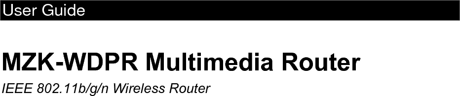
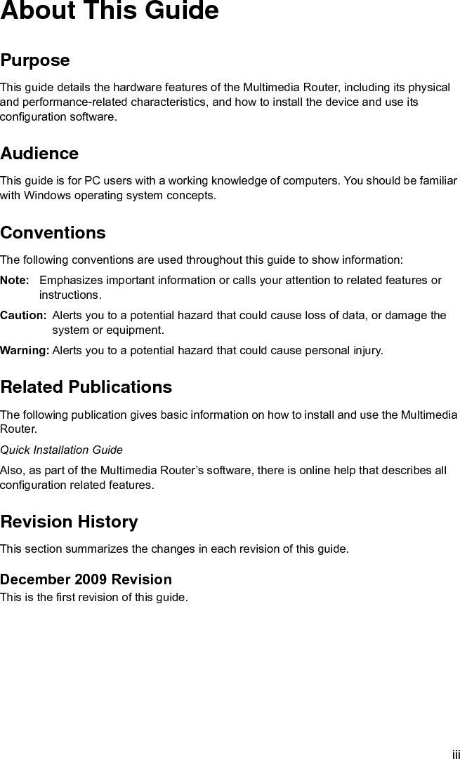


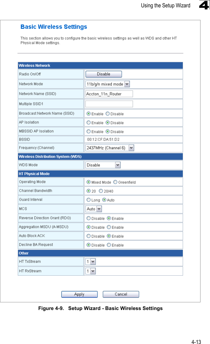
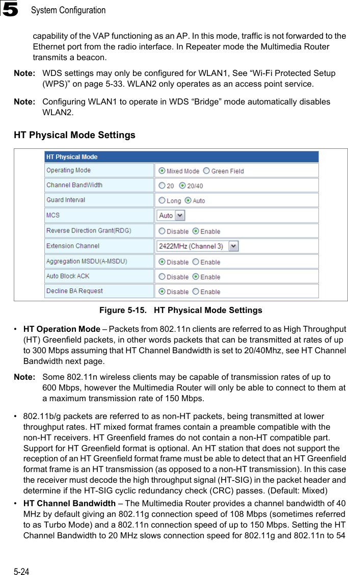
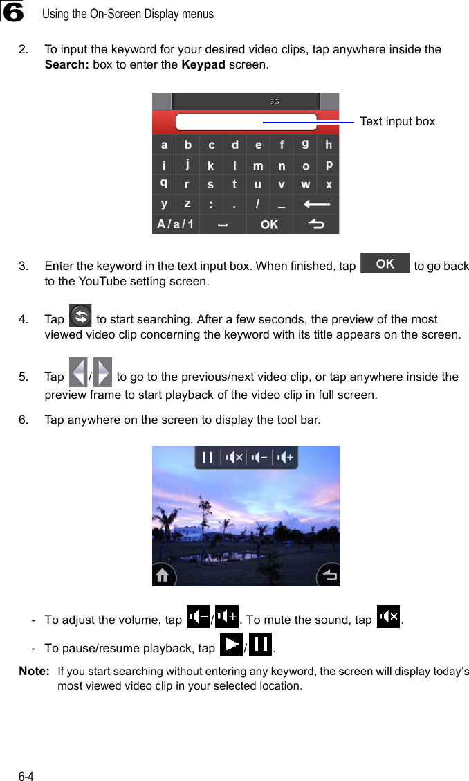
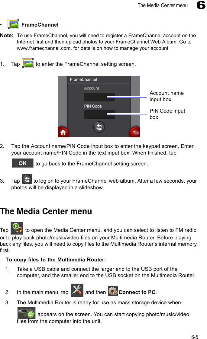
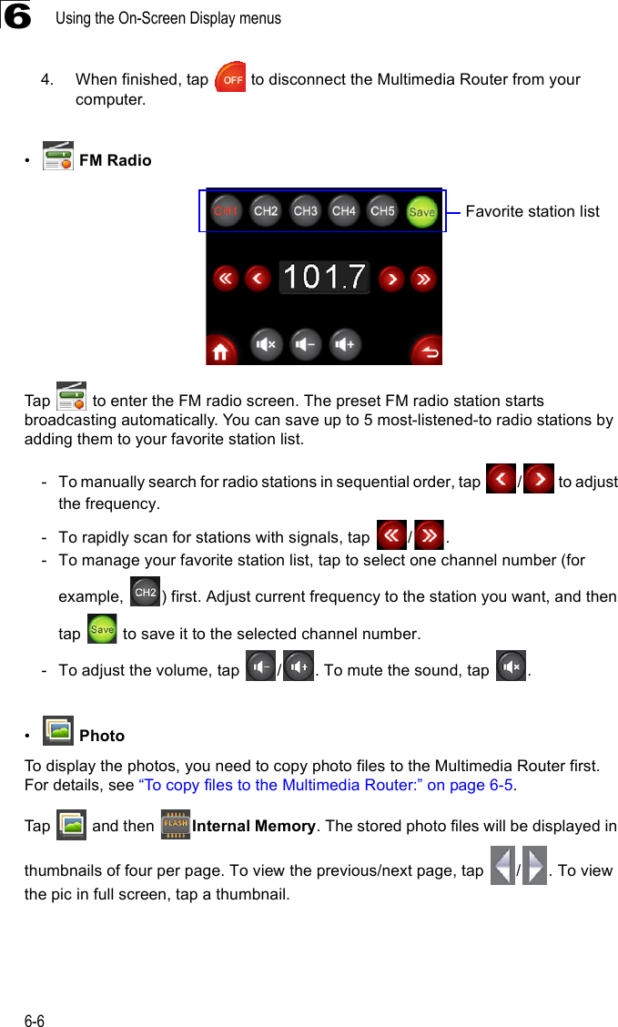
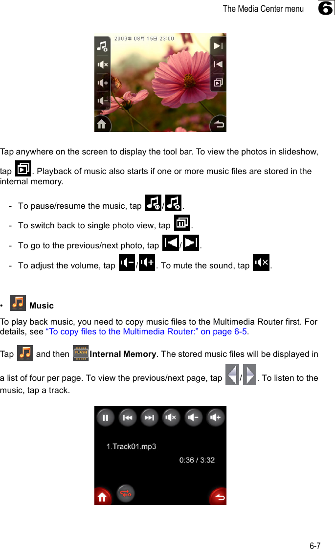
![Wireless Settings5-255Mbps and 74 Mbps respectively and ensures backward compliance for slower 802.11b devices. (Default: 20/40MHz)•Guard Interval – The guard interval between symbols helps receivers overcome the effects of multipath delays. When you add a guard time, the back portion of useful signal time is copied and appended to the front. (Default: Auto)•MCS – The Modulation and Coding Scheme (MCS) is a value that determines the modulation, coding and number of spatial channels. (Options: value [range] = 0~7 (1 Tx Stream), 8~15 (2 TxStream), 32 and auto (33). Default: auto)•Reverse Direction Grant (RDG) – When enables Reverse Direction Grant, the Multimedia Router can reduce the transmitted data packet collision by using the reverse direction protocol. During TXOP (Transmission Opportunity) period, the receiver could use remaining transmission time to transmit data to a sender. The RDG improves transmission performance and scalability in a wireless environment. •Extension Channel – When 20/40MHz channel bandwidth has been set, the extension channel option will be enabled. The extension channel will allow you to get extra bandwidth. (Options: 2417MHz/Channel 2, 2457MHz/Channel 10. Default: 2457MHz/Channel 10.)•Aggregate MSDU (A-MSDU) – This option enables Mac Service Data Unit (MSDU) aggregation. (Default: Disable)•Auto Block ACK – Select to block ACK (Acknowledge Number) or not during data transferring.•Decline BA Request – Select to reject peer BA-Request or not.Other HT SettingsFigure 5-16. HT Physical Mode Settings•HT TxStream – HT means High Throughput. The number of HT TxStream means how many antennas will transmit data simultaneously. (Options: 1 or 2. Default: 2)•HT RxStream – The number of HT RxStream means how many antennas will receive data simultaneously. (Options: 1 or 2. Default: 2)Advanced Wireless SettingsThe Advanced Setting page allows you to configure the more advanced radio settings, many of which are enabled by default.Click “Wireless Settings” followed by “Advanced”.](https://usermanual.wiki/Qisda/AT035N00/User-Guide-1209766-Page-61.png)