Qisda AT035N00 MULTIMEDIA ROUTER User Manual MZK WDPR ug
Qisda Corporation MULTIMEDIA ROUTER MZK WDPR ug
Qisda >
Users Manual

User Guide
Guide
MZK-WDPR Multimedia Router
IEEE 802.11b/g/n Wireless Router


i
Compliances
EC Conformance Declaration
Marking by the above symbol indicates compliance with the Essential Requirements of
the R&TTE Directive of the European Union (1999/5/EC). This equipment meets the
following conformance standards:
• EN 60950-1 (IEC 60950-1) - Product Safety
• EN 300 328 - Technical requirements for 2.4 GHz radio equipment
• EN 301 489-1, EN 301 489-17 - EMC requirements for radio equipment
This device is intended for use in the following European Community and EFTA countries:
Requirements for indoor vs. outdoor operation, license requirements and allowed
channels of operation apply in some countries as described below:
• In Italy the end-user must apply for a license from the national spectrum authority to
operate this device outdoors.
• In Belgium outdoor operation is only permitted using the 2.46 - 2.4835 GHz band:
Channel 13.
• In France outdoor operation is only permitted using the 2.4 - 2.454 GHz band: Channels
1 - 7.
FCC statement
This device complies with Part 15 of the FCC Rules. Operation is subject to the following
two conditions: (1) this device may not cause harmful interference, and (2) this device
must accept any interference received, including interference that may cause undesired
operation.
This equipment has been tested and found to comply with the limits for a Class B digital
device, pursuant to Part 15 Subpart B of the FCC Rules. These limits are designed to
provide reasonable protection against harmful interference in a residential installation.
This equipment generates, uses, and can radiate radio frequency energy, and if not
installed and used in accordance with the instructions, may cause harmful interference to
radio communications. However, there is no guarantee that interference will not occur in a
particular installation. If this equipment does cause harmful interference to radio or
television reception, which can be determined by turning the equipment off and on, the
user is encouraged to try to correct the interference by one or more of the following
measures:
• Austria • Belgium • Cyprus • Czech Republic • Denmark
• Estonia • Finland • France • Germany • Greece
• Hungary • Iceland • Ireland • Italy • Latvia
• Liechtenstein • Lithuania • Luxembourg • Malta • Netherlands
• Norway • Poland • Portugal • Slovakia • Slovenia
• Spain • Sweden • Switzerland • United Kingdom •

ii
• Reorient or relocate the receiving antenna.
• Increase the separation between the equipment and receiver.
• Connect the equipment into an outlet on a circuit different from that to which the receiver
is connected.
• Consult the dealer or an experienced radio/TV technician for help.
For product available in the USA/Canada market, only channel 1~11 can be operated.
Selection of other channels is not possible.
FCC Caution: Any changes or modifications not expressly approved by the party
responsible for compliance could void the user's authority to operate this equipment.
This device and its antenna(s) must not be co-located or operating in conjunction with any
other antenna or transmitter.
FCC Radiation Exposure Statement:
This equipment complies with FCC radiation exposure limits set forth for an uncontrolled
environment. This equipment should be installed and operated with minimum distance
20cm between the radiator & your body.

iii
About This Guide
Purpose
This guide details the hardware features of the Multimedia Router, including its physical
and performance-related characteristics, and how to install the device and use its
configuration software.
Audience
This guide is for PC users with a working knowledge of computers. You should be familiar
with Windows operating system concepts.
Conventions
The following conventions are used throughout this guide to show information:
Note: Emphasizes important information or calls your attention to related features or
instructions.
Caution: Alerts you to a potential hazard that could cause loss of data, or damage the
system or equipment.
Warning: Alerts you to a potential hazard that could cause personal injury.
Related Publications
The following publication gives basic information on how to install and use the Multimedia
Router.
Quick Installation Guide
Also, as part of the Multimedia Router’s software, there is online help that describes all
configuration related features.
Revision History
This section summarizes the changes in each revision of this guide.
December 2009 Revision
This is the first revision of this guide.

iv

Table of Contents
Chapter 1: Introduction 1-1
Package Checklist 1-1
Hardware Description 1-2
Power Socket 1-3
USB Port 1-3
PC Port 1-3
Chapter 2: Installation 2-1
Gateway Mode 2-1
Bridge Mode 2-2
Chapter 3: Network Planning 3-1
Internet Gateway Router 3-1
LAN Access Point 3-2
Wireless Bridge 3-3
Chapter 4: Initial Configuration 4-1
Using the Setup Wizard 4-2
DHCP 4-2
Static IP 4-4
PPPoE 4-5
L2TP 4-7
PPTP 4-8
3G 4-10
Chapter 5: System Configuration 5-1
Operation Mode configuration 5-4
Network Settings 5-4
WAN Setting 5-4
DHCP 5-5
PPPoE 5-8
L2TP 5-10
PPTP 5-12
3G 5-14
LAN Setting 5-16

Contents
Advanced Routing 5-18
Wireless Settings 5-20
Basic Settings 5-20
Advanced Wireless Settings 5-25
WLAN Security 5-30
Wi-Fi Protected Setup (WPS) 5-33
Station List 5-35
Firewall 5-35
MAC/IP/Port Filtering 5-36
Virtual Server Settings (Port Forwarding) 5-37
System Security 5-39
Content Filtering 5-40
Administration Settings 5-42
System Management 5-42
Upgrade Firmware 5-44
Configuration Settings 5-45
System Status 5-46
Statistics 5-48
DHCP Clients 5-49
System Log 5-49
Reboot 5-50
Chapter 6: Using the On-Screen Display menus 6-1
Using the menus 6-1
Updating the Firmware 6-2
Using the Keypad 6-2
The Internet menu 6-3
The Media Center menu 6-5
The Calendar menu 6-8
The Tools menu 6-10
Appendix A: Troubleshooting A-1
Appendix B: Specifications B-1
Glossary
Index

1-1
Chapter 1: Introduction
The Multimedia Router is an IEEE 802.11b/g/n wireless gateway router that connects
your Internet access device (cable or ADSL modem) to your PC or local area network, or
to its own secure wireless network.
The Multimedia Router is also equipped with a touch-sensitive screen, two speakers, and
128MB built-in memory that provide multimedia functions such as FM/Internet radio,
photo display, and audio/video playback. You can also view video clips from YouTube and
get access to your FrameChannel account once connected to the Internet.
Package Checklist
The Multimedia Router package includes:
• Multimedia Router
• RJ-45 Category 5 network cable
• AC power adapter
• Quick Installation Guide
• User Guide CD
• Warranty card
Inform your dealer if there are any incorrect, missing or damaged parts. If possible, retain
the carton, including the original packing materials. Use them again to repack the product
in case there is a need to return it.
Introduction
1-2
1
Hardware Description
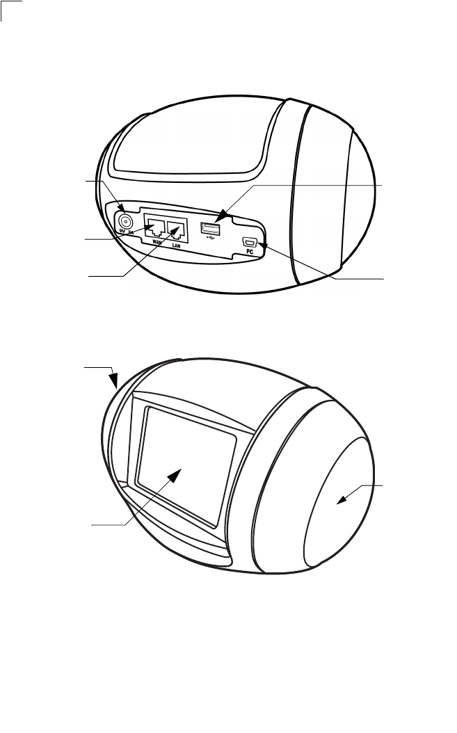
Figure 1-1. Rear Panel
Figure 1-2. Front Panel
Ethernet WAN
RJ-45 Port
Power Socket
Ethernet LAN
RJ-45 Port PC Port
USB Port
Speaker
Speaker
Touch-sensitive
screen

Hardware Description
1-3
1
Ethernet RJ-45 Ports
The Multimedia Router has the following RJ-45 ports:
• The RJ-45 LAN port is for connection to a PC or to a 10/100 Mbps.
• The RJ-45 WAN port is for connection to a DSL or cable modem, or to a LAN or other
device that provides your Internet access.
All RJ-45 ports auto-negotiate the operating speed to 10/100 Mbps, the mode to half/full
duplex, and the pin signals to MDI/MDI-X. Automatic MDI/MDI-X support enables you to
use straight-through cables for all network connections to PCs, switches, or hubs.
Power Socket
The Multimedia Router does not have a power switch. It is powered on when connected
to the AC power adapter, and the power adapter is connected to a power source. The
power adapter automatically adjusts to any voltage between 220-240 volts at 50Hz. No
voltage range settings are required.
USB Port
The USB port is for connection to a USB modem that provides wireless Internet access.
PC Port
The PC Port is for file transfer between the Multimedia Router and your PC.

Introduction
1-4
1

2-1
Chapter 2: Installation
The Multimedia Router has two basic operating modes that can be set through the
web-based management interface. For information on setting the mode suitable for your
network environment, see “Operation Mode configuration” on page 5-4.
•Gateway Mode — A gateway mode that connects a wired LAN and wireless clients to
an Internet access device, such as a cable or DSL modem. This is the factory set default
mode.
•Bridge Mode — An access point mode that extends a wired LAN to wireless clients.
•AP Client Mode — Appears only when you’ve selected the Bridge Mode in the Setup
Wizard. The wireless application interface is treated as WAN port, and the wireless ap
interface and the ethernet ports are LAN ports.
In addition to these basic operating modes, the wireless interface supports a Wireless
Distribution System (WDS) link to another Multimedia Router. These advanced
configurations are not described in this section. See “Network Planning” on page 3-1 for
more information.
In a basic configuration, how the Multimedia Router is connected depends on the
operating mode. The following sections describe connections for basic Gateway Mode
and Bridge Mode operation.
Gateway Mode
In its default Gateway Mode, the Multimedia Router forwards traffic between an Internet
connected cable or ADSL modem, and wired or wireless PCs or notebooks. The basic
connections are illustrated in the figure below.
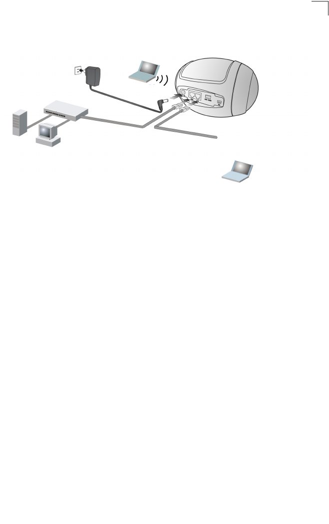
Figure 2-1. Gateway Mode Connection
Internet
Cable/DSL Modem
Connect WAN port to
cable/DSL modem
1.
Connect AC power
adapter to power
source
3. Set up wireless
devices
4.
Notebook PC
Connect LAN
port to PC
2.

Installation
2-2
2
To connect the Multimedia Router in Gateway Mode for use as an Internet gateway, follow
these steps:
1. Connect an Ethernet cable from the Multimedia Router’s WAN port to your Internet
connected cable or ADSL modem.
2. Connect an Ethernet cable from the Multimedia Router’s LAN port to your PC.
Alternatively, you can connect to a workgroup switch to support multiple users. The
Multimedia Router can support wired and wireless users.
3. Power on the Multimedia Router by connecting the AC power adapter and plugging
it into a power source.
Caution: Use ONLY the power adapter supplied with the Multimedia Router. Otherwise,
the product may be damaged.
4. Set up wireless devices by going to Tools > Network Setting > Router Setting
On-Screen Display (OSD) menu or by using the web interface. See “Initial
Configuration” on page 4-1 for more information on accessing the web interface. For
details on how to use the OSD menus, see “Using the On-Screen Display menus” on
page 6-1.
Bridge Mode
In Bridge Mode, the Multimedia Router operates as a wireless access point, extending a
local wired network to associated wireless clients (PCs or notebooks with wireless
capability). From any nearby location, you can then make a wireless connection to the
Multimedia Router and access the wired network resources, including local servers and
the Internet.
In Bridge Mode, the Multimedia Router does not support gateway functions on its WAN
port. Both the LAN port and the WAN port can be connected to a local Ethernet LAN.
Note: Bridge Mode is not the factory default mode and must be manually set using the
web management interface.
Bridge Mode
2-3
2
Figure 2-2. Bridge Mode Connection
To connect the Multimedia Router for use as an access point, follow these steps:
1. Connect an Ethernet cable from the Multimedia Router’s LAN and WAN ports to PCs
or a LAN switch.
2. Power on the Multimedia Router by connecting the AC power adapter and plugging
it into a power source.
Caution: Use ONLY the power adapter supplied with the Multimedia Router. Otherwise,
the product may be damaged.
3. Set up wireless devices by going to Tools > Network Setting > Network Setting
On-Screen Display (OSD) menu or by using the web interface. See “Initial
Configuration” on page 4-1 for more information on accessing the web interface. For
details on how to use the OSD menus, see “Using the On-Screen Display menus” on
page 6-1.
Server
Connect AC power
adapter to power
source
2.
Desktop PCs
LAN Switch
Set up wireless
devices
3.
Notebook PC
Connect LAN and WAN
ports to an Ethernet LAN
switch or PCs
1. Connect LAN port
to PC
2.

Installation
2-4
2
3-1
Chapter 3: Network Planning
The Multimedia Router is designed to be very flexible in its deployment options. It can be
used as an Internet gateway for a small network, or as an access point to extend an
existing wired network to support wireless users. It also supports use as a wireless bridge
to connect two wired LANs.
This chapter explains some of the basic features of the Multimedia Router and shows
some network topology examples in which the device is implemented.
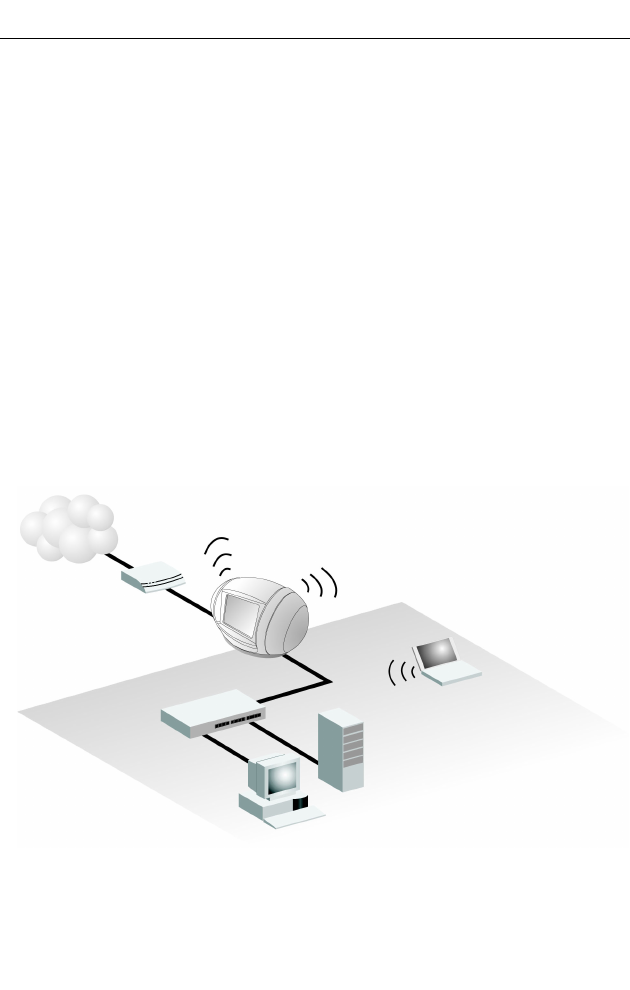
Internet Gateway Router
The Multimedia Router can connect directly to a cable or DSL modem to provide an
Internet connection for multiple users through a single service provider account. Users
can connect to the Multimedia Router either through a wired connection to a LAN port, or
though the device’s own wireless network. The Multimedia Router functions as an Internet
gateway when set to Gateway Mode.
An Internet gateway employs several functions that essentially create two separate
Internet Protocol (IP) subnetworks; a private internal network with wired and wireless
users, and a public external network that connects to the Internet. Network traffic is
forwarded, or routed, between the two subnetworks.
Figure 3-1. Operating as an Internet Gateway Router
Internet
service
provider
Cable/DSL
Modem
Multimedia
Router
Notebook PC
(IP: 192.168.2.x)
LAN Switch
Server
(IP: 192.168.2.x)
Desktop PC
(IP: 192.168.2.x)
WAN (IP assigned from ISP)
LAN: (IP: 192.168.2.x)
Network Planning
3-2
3
The private local network, connected to the LAN port or wireless interface, provides a
Dynamic Host Configuration Protocol (DHCP) server for allocating IP addresses to local
PCs and wireless clients, and Network Address Translation (NAT) for mapping the
multiple "internal" IP addresses to one "external" IP address.
The public external network, connected to the WAN port, supports DHCP client,
Point-to-Point Protocol over Ethernet (PPPoE), static IP for connection, L2TP and PPTP
to an Internet service provider (ISP) through a cable or DSL modem.
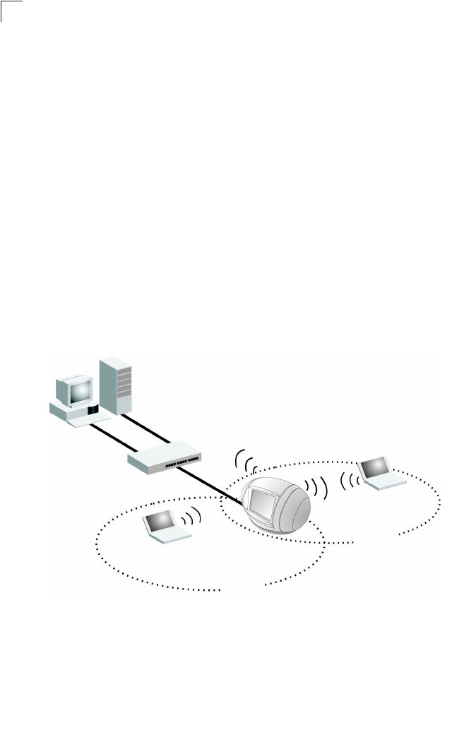
LAN Access Point
The Multimedia Router can provide an access point service for an existing wired LAN,
creating a wireless extension to the local network. The Multimedia Router functions as
purely an access point when set to Bridge Mode. When used in this mode, there are no
gateway functions between the WAN port and the LAN and wireless interface.
A Wi-Fi wireless network is defined by its Service Set Identifier (SSID) or network name.
Wireless clients that want to connect to a network must set their SSID to the same SSID
of the network service. The Multimedia Router supports two separate wireless interfaces,
that is two SSIDs or Virtual Access Points (VAPs). The two VAP interfaces can be
configured separately to support different security settings or other wireless functions.
Figure 3-2. Operating as an Access Point
Desktop PC
(IP: 192.168.2.x)
LAN Switch
Multimedia Router
Notebook PC
(IP: 192.168.2.x)
SSID 1
(public)
Server
(IP: 192.168.2.x)
Notebook PC
(IP: 192.168.2.x)
SSID 2
(private)
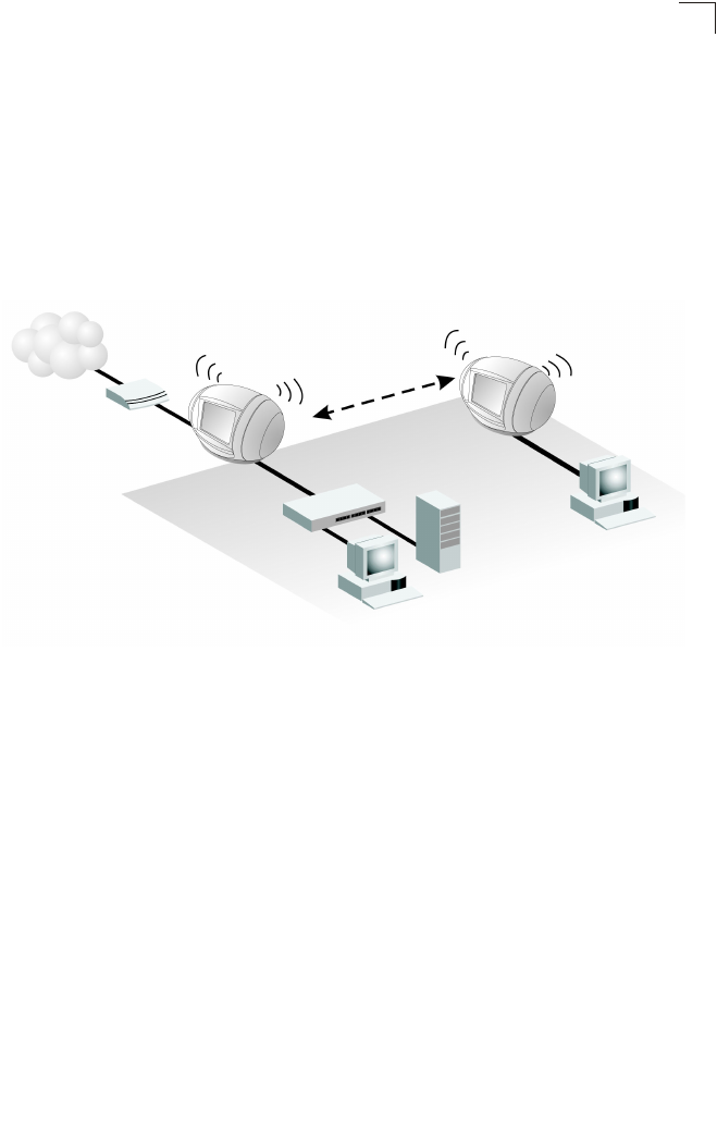
Wireless Bridge
3-3
3
Wireless Bridge
The IEEE 802.11 standard defines a Wireless Distribution System (WDS) for bridge
connections between access points. The Multimedia Router can use WDS to forward
traffic on links between units.
A single WDS bridge link can be specified for the WLAN1 interface. One end of a link
must be configured as the “WDS Parent” and the other as the “WDS Child.”
Note: The network domain of WDS child has to be the same as WDS parent.
Figure 3-3. Operating as a Wireless Bridge
Internet
service
provider
Cable/DSL
Modem Multimedia Router
(Gateway Mode)
Desktop PC
(IP: 192.168.2.x)
LAN Switch
Server
(IP: 192.168.2.x)
WAN
(IP from ISP)
WDS Parent
WDS Link
WDS Child
Multimedia Router
(Bridge Mode)
LAN
(IP: 192.168.2.x)
Desktop PC
(IP: 192.168.2.x)

Network Planning
3-4
3
4-1
Chapter 4: Initial Configuration
The Multimedia Router offers a user-friendly web-based management interface for the
configuration of all the unit’s features. Any PC directly attached to the unit can access the
management interface using a web browser, such as Internet Explorer (version 6.0 or
above).
This chapter describes the Multimedia Router’s configurative features, all of which may
be accessed through the web interface.
It is recommended to make initial configuration changes by connecting a PC directly to
the Multimedia Router's LAN port. The Multimedia Router has a default IP address of
192.168.2.1 and a subnet mask of 255.255.255.0. If your PC is set to “Obtain an IP
address automatically” (that is, set as a DHCP client), you can connect immediately to the
web interface. Otherwise, you must set your PC IP address to be on the same subnet as
the Multimedia Router (that is, the PC and Multimedia Router addresses must both start
192.168.2.x).
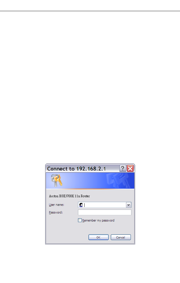
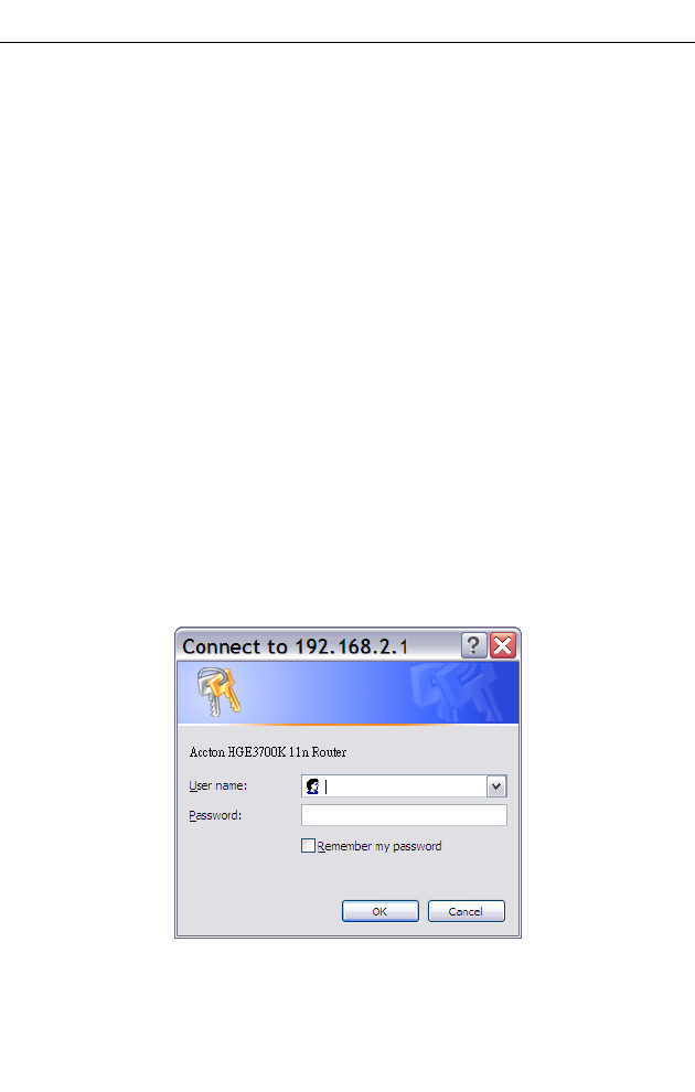
To access the configuration menu, follow these steps:
1. Use your web browser to connect to the management interface using the default IP
address of 192.168.2.1.
2. Log into the Multimedia Router management interface by entering the default
username “admin” and password “admin”, then click OK.
Note: It is strongly recommended to change the default user name and password the
first time you access the web interface. For information on changing user names
and passwords, See “Administrator Settings” on page 5-43.
Figure 4-1. Login Page
Initial Configuration
4-2
4
Using the Setup Wizard
There are only a few basic steps you need to set up the Multimedia Router and provide a
connection for network access for other wireless stations.
The Setup Wizard takes you through configuration procedures for the general network
settings. Follow these steps:
1. Launch the Setup Wizard – Click “Setup Wizard” on the left side of the screen to
enter the setup wizard page.
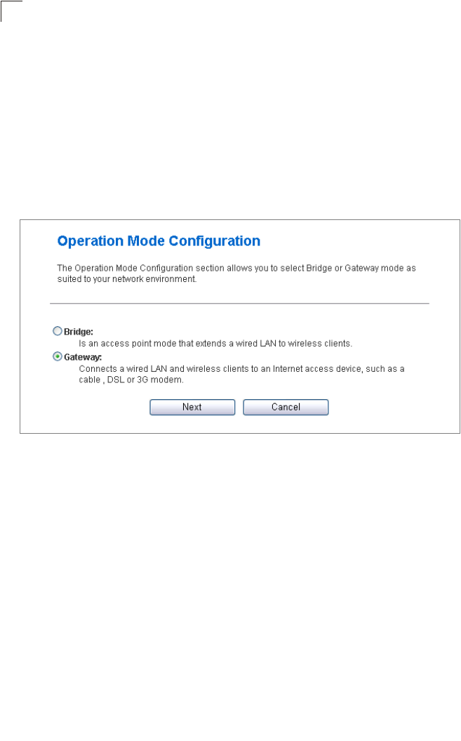
2. Operation Mode Configuration – Select the operation mode required for the
network environment. Click “Next” to continue the setup.
Figure 4-2. Setup Wizard - Operation Mode
3. WAN Configuration – Specifies the Internet connection parameters for the
Multimedia Router’s WAN port. Click Next after completing the setup.
WAN Connection Type — By default, the access point WAN port is configured with
DHCP enabled. After you have network access to the access point, you can use the web
browser interface to modify the initial IP configuration, if needed. The options are Static IP,
DHCP, PPPoE (ADSL), L2TP, PPTP and 3G. Each option changes the parameters
displayed below it. (Default: DHCP).
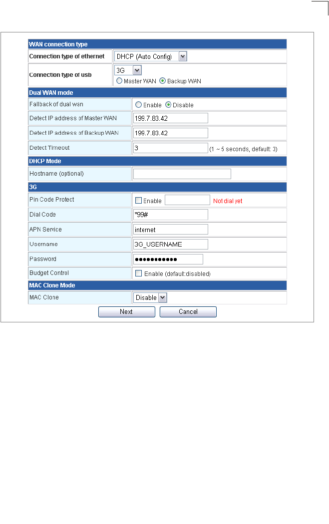
DHCP
Enables Dynamic Host Configuration Protocol (DHCP) for the WAN port. This setting
allows the Multimedia Router to automatically obtain an IP address from a DHCP server
normally operated by the Internet Service Provider (ISP).
Using the Setup Wizard
4-3
4
Figure 4-3. Setup Wizard - WAN DHCP
•Hostname – The hostname of the DHCP client.
•MAC Clone Mode – Some ISPs limit Internet connections to a specified MAC address
of one PC. This setting allows you to manually change the MAC address of the
Multimedia Router's WAN interface to match the PC's MAC address provided to your
ISP for registration. You can enter the registered MAC address manually by typing it in
the boxes provided. Otherwise, connect only the PC with the registered MAC address
to the Multimedia Router, then click the “Fill My MAC” (Default: Disable)
Note: If you are unsure of the PC MAC address originally registered by your ISP, call
your ISP and request to register a new MAC address for your account. Register
the default MAC address of the Multimedia Router.
Initial Configuration
4-4
4
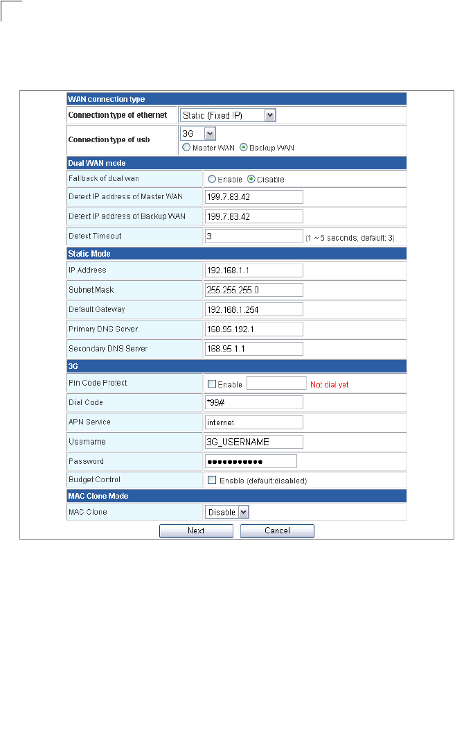
Static IP
Configures a static IP for the WAN port.
Figure 4-4. Setup Wizard - WAN Static IP
•IP Address – The IP address of the Multimedia Router. Valid IP addresses consist of
four decimal numbers, 0 to 255, separated by periods.
•Subnet Mask – The mask that identifies the host address bits used for routing to specific
subnets.
•Default Gateway – The IP address of the gateway router for the Multimedia Router,
which is used if the requested destination address is not on the local subnet.
•Primary DNS Server – The IP address of the Primary Domain Name Server on the
network. A DNS maps numerical IP addresses to domain names and can be used to
identify network hosts by familiar names instead of the IP addresses. If you have one or

Using the Setup Wizard
4-5
4
more DNS servers located on the local network, type the IP addresses in the text fields
provided. Otherwise, leave the addresses as all zeros (0.0.0.0).
•Secondary DNS Server – The IP address of the Secondary Domain Name Server on
the network.
•MAC Clone Mode – Some ISPs limit Internet connections to a specified MAC address
of one PC. This setting allows you to manually change the MAC address of the
Multimedia Router's WAN interface to match the PC's MAC address provided to your
ISP for registration. You can enter the registered MAC address manually by typing it in
the boxes provided. Otherwise, connect only the PC with the registered MAC address
to the Multimedia Router, then click the “Fill My MAC” (Default: Disable)
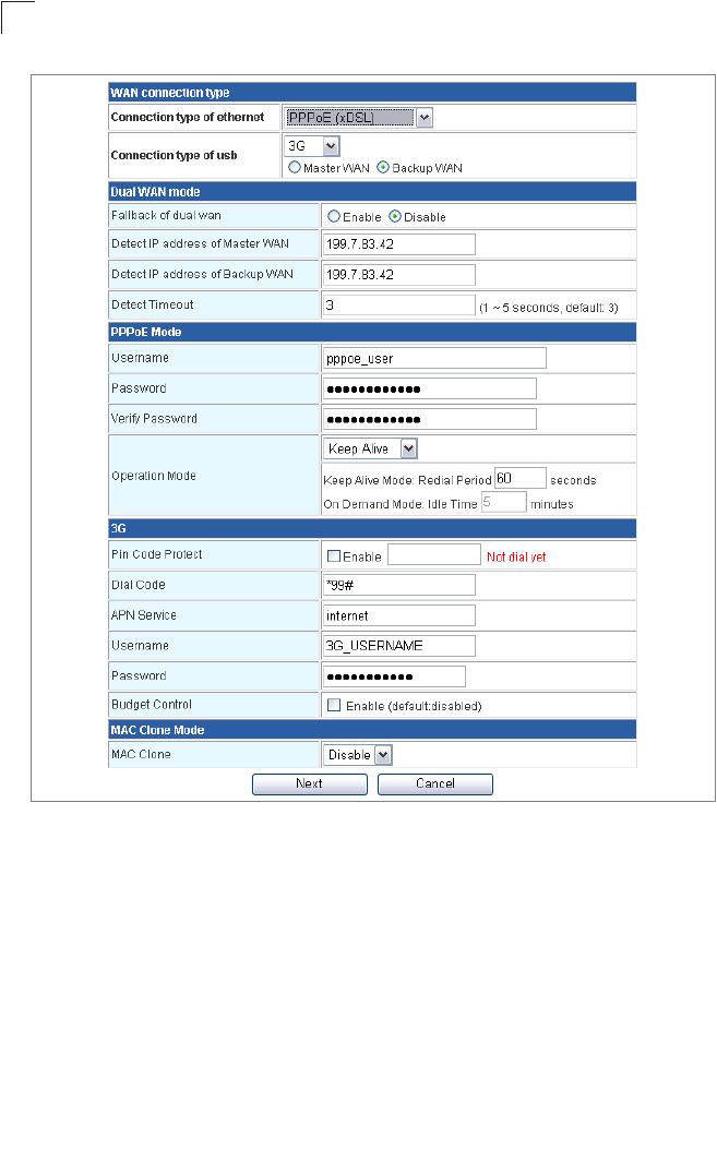
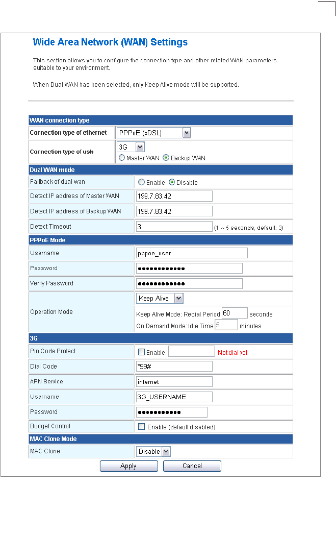
PPPoE
Enable the Multimedia Router IP address to be assigned automatically from an Internet
service provider (ISP) through an xDSL modem using Point-to-Point Protocol over
Ethernet (PPPoE).
Initial Configuration
4-6
4
Figure 4-5. Setup Wizard - WAN PPPoE
•PPPoE Username – Sets the PPPoE user name for the WAN port.
(Default: pppoe_user; Range: 1~32 characters)
•PPPoE Password – Sets a PPPoE password for the WAN port.
(Default: pppoe_password; Range: 1~32 characters)
•Verify Password – Prompts you to re-enter your chosen password.
•MAC Clone Mode – Some ISPs limit Internet connections to a specified MAC address
of one PC. This setting allows you to manually change the MAC address of the
Multimedia Router's WAN interface to match the PC's MAC address provided to your
ISP for registration. You can enter the registered MAC address manually by typing it in
the boxes provided. Otherwise, connect only the PC with the registered MAC address
to the Multimedia Router, then click the “Fill My MAC” (Default: Disable)
Using the Setup Wizard
4-7
4
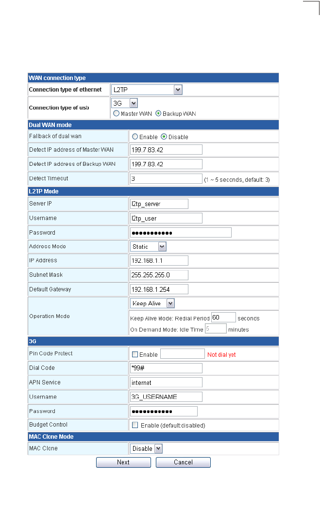
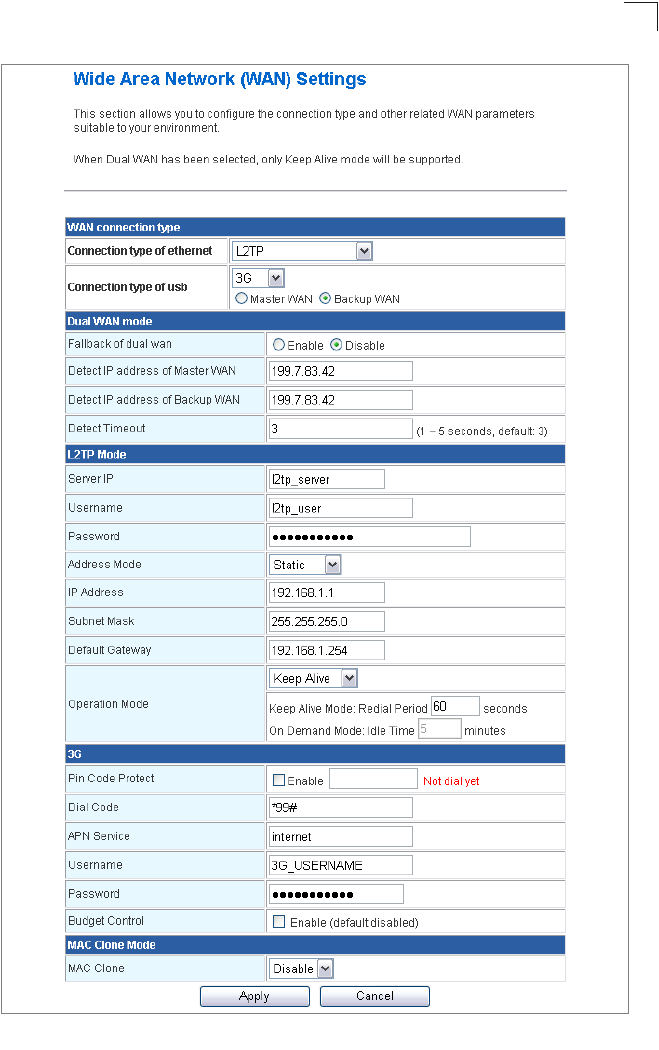
L2TP
Enables the Layer Two Tunneling Protocol (L2TP) for implementing virtual private
networks. The service is provided in many European countries.
Figure 4-6. Setup Wizard - WAN L2TP

Initial Configuration
4-8
4
•Server IP – Sets the L2TP server IP Address.
(Default: l2tp_server; Range: 1~32 characters)
•Username – Sets the L2TP user name for the WAN port.
(Default: l2tp_user; Range: 1~64 characters)
• Password – Sets a L2TP password for the WAN port. (Default: l2tp_password; Range:
1~32 characters)
•Verify Password – Prompts you to re-enter your chosen password.
•Address Mode – Sets a L2TP network mode. (Default: Static)
•IP Address – Sets the static IP address. (Default: 0.0.0.0, available when L2TP Network
Mode is set to static IP.)
•Subnet Mask – Sets the static IP subnet mask. (Default: 255.255.255.0, available when
L2TP Network Mode is set to static IP.)
•Default Gateway – The IP address of the gateway router for the Multimedia Router,
which is used if the requested destination address is not on the local subnet.
•MAC Clone Mode – Some ISPs limit Internet connections to a specified MAC address
of one PC. This setting allows you to manually change the MAC address of the
Multimedia Router's WAN interface to match the PC's MAC address provided to your
ISP for registration. You can enter the registered MAC address manually by typing it in
the boxes provided. Otherwise, connect only the PC with the registered MAC address
to the Multimedia Router, then click the “Fill My MAC” (Default: Disable)
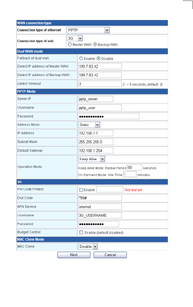
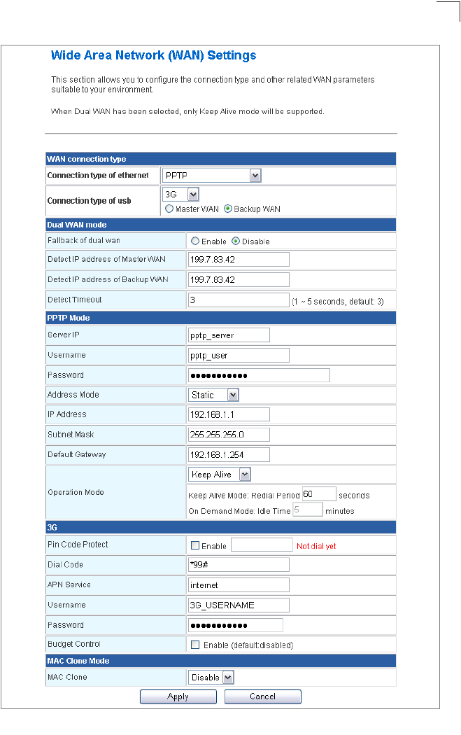
PPTP
Enables the Point-to-Point Tunneling Protocol (PPTP) for implementing virtual private
networks. The service is provided in many European countries.
Using the Setup Wizard
4-9
4
Figure 4-7. Setup Wizard - PPTP
•Server IP – Sets a PPTP server IP Address. (Default: pptp_server)
•Username – Sets the PPTP user name for the WAN port.
(Default: pptp_user; Range: 1~64 characters)
•Password – Sets a PPTP password for the WAN port. (Default: pptp_password; Range:
1~32 characters)

Initial Configuration
4-10
4
•Verify Password – Prompts you to re-enter your chosen password.
•Address Mode – Sets a PPTP network mode. (Default: Static)
•IP Address – Sets the static IP address. (Default: 0.0.0.0, available when PPTP
Network Mode is set to static IP.)
•Subnet Mask – Sets the static IP subnet mask. (Default: 255.255.255.0, available when
PPTP Network Mode is set to static IP.)
•Default Gateway – The IP address of the gateway router for the Multimedia Router,
which is used if the requested destination address is not on the local subnet.
•Operation Mode – Selects the operation mode as Keep Alive, On Demand or Manual.
(Default: Keep Alive)
-Keep Alive Mode: The Multimedia Router will periodically check your Internet
connection and automatically re-establish your connection when disconnected.
(Default: 60 seconds)
-On Demand Mode: The maximum length of inactive time the unit will stay connected
to the DSL service provider before disconnecting. This feature only works when
Connect Type is set to "Auto-Connect". (Default: 5 minutes)
•MAC Clone Mode – Some ISPs limit Internet connections to a specified MAC address
of one PC. This setting allows you to manually change the MAC address of the
Multimedia Router's WAN interface to match the PC's MAC address provided to your
ISP for registration. You can enter the registered MAC address manually by typing it in
the boxes provided. Otherwise, connect only the PC with the registered MAC address
to the Multimedia Router, then click the “Fill My MAC” (Default: Disable)
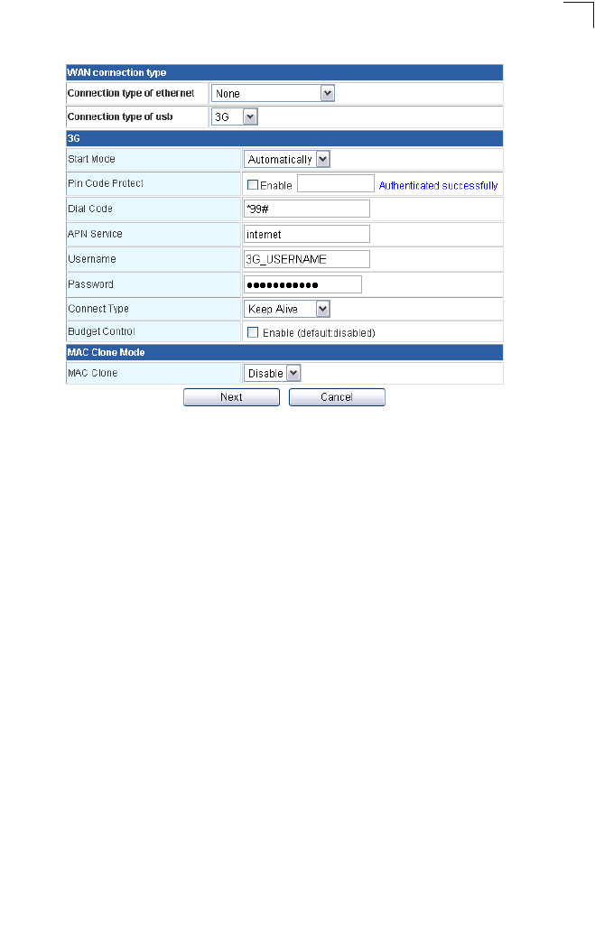
3G
Enables a 3G/3.5G wide-area wireless cellular link on the WAN port using an optional
USB modem.
Note: To use this option, you need to first connect a 3G/3.5G USB modem to the USB
port on the back of the unit and have registered an account with a cellular
operator.
An authenticated 3G connection displays the message “Authenticated successfully”
beneath the PIN code. An unauthenticated connection will display the message “Not dial
yet” beneath the PIN code. However if you have previously entered the correct PIN code
followed by an incorrect PIN code, your connection will wait ten seconds and
automatically default to the correct PIN code for authentication.
Using the Setup Wizard
4-11
4
Figure 4-8. Setup Wizard - 3G
•Pin Code Protect – Enables the use of a PIN code (personal identification number) to
encrypt access to the wireless 3G connection. Some service providers do not require
PIN code authentication. If the PIN code for your 3G/3.5G modem is disabled, disable
this function (Default: Enabled). Specifies a PIN code number that corresponds with that
set on your 3G/3.5G USB modem and displays the status of the 3G connection.
-Not dial yet: Indicates that the PIN code has not been entered or is incorrect.
-Authenticated successfully: Indicates that the 3G connection has
authenticated successfully.
•Dial Code: A dialled access code that connects the USB device to the service provider.
•APN Service: The name that uniquely identifies the cellular operator, access point
name (APN).
•3G Username: The username of the account registered with the service provider.
•3G Password: The password of the account registered with the service provider.
•Connect Type: Selects the connection type as Keep Alive or Auto Connect.
(Default: Auto Connect)
•3G Max Idle Time: The maximum length of inactive time the unit will stay connected to
the DSL service provider before disconnecting. This feature only works when Connect
Type is set to “Auto-Connect.” (Default: 300 seconds)
•Budget Control: You can set a monthly limit on time or the total data. For more details,
please refer to the following table.
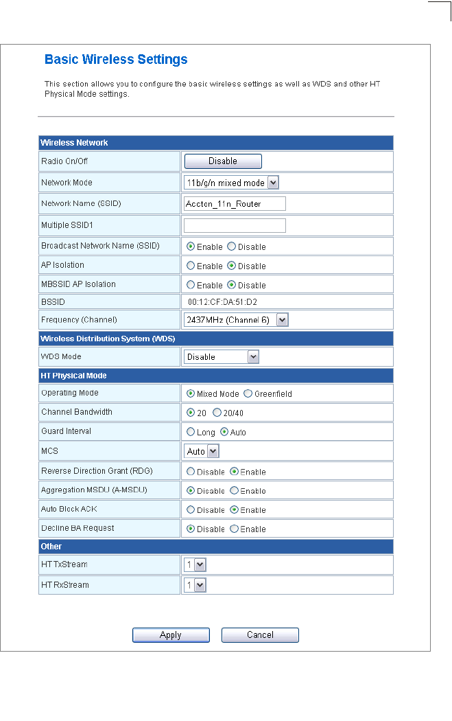
4. Basic Wireless Settings – Configures the SSID and sets the wireless security
policy. Click Apply after completing the setup.

Initial Configuration
4-12
4
By Time By Data
Budget Criterion Specify the amount of time (in
hours) that can be used per month
Specify how much Download/Upload data (in
MBytes) can be transmitted per month
Budget Policy Enable or disable the action “Drop
Current Cellular connection” if
over budget
Enable or disable the action “Disallow New
Cellular connection” if over budget
*Trigger by Limit
Budget
Set the specified % of time limit Set the specified % of time limit
Action taken when the
specified % of time or
data limit is exceeded
Send an E-mail alert Recur every certain minutes
Budget Counter Select the date which the AP/Router resets the budget every month
Using the Setup Wizard
4-13
4
Figure 4-9. Setup Wizard - Basic Wireless Settings

Initial Configuration
4-14
4
•Network Name (SSID) – The name of the wireless network service provided by the
VAP. Clients that want to connect to the network must set their SSID to the same as that
of the VAP interface. (Default: “Accton_11n_Router”; Range: 1-32 characters)
•Security Policy – Configures the security mode used by clients. See “WLAN Security”
on page 5-30.
5-1
Chapter 5: System Configuration
The Multimedia Router offers a user-friendly web-based management interface for the
configuration of all the unit’s features. Any PC directly attached to the unit can access the
management interface using a web browser, such as Internet Explorer (version 6.0 or
above).
This chapter describes the Multimedia Router’s configurable features, all of which may be
accessed through the web interface.
It is recommended to make initial configuration changes by connecting a PC directly to
the Multimedia Router's LAN port. The Multimedia Router has a default IP address of
192.168.2.1 and a subnet mask of 255.255.255.0. If your PC is set to “Obtain an IP
address automatically” (that is, set as a DHCP client), you can connect immediately to the
web interface. Otherwise, you must set your PC IP address to be on the same subnet as
the Multimedia Router (that is, the PC and Multimedia Router addresses must both start
192.168.2.x).
To access the configuration menu, follow these steps:
1. Use your web browser to connect to the management interface using the default IP
address of 192.168.2.1.
2. Log into the Multimedia Router management interface by entering the default
username “admin” and password “admin”, and then click OK.
Note: It is strongly recommended to change the default user name and password the
first time you access the web interface. For information on changing user names
and passwords, See “Administrator Settings” on page 5-43.
Figure 5-1. Login Page
System Configuration
5-2
5
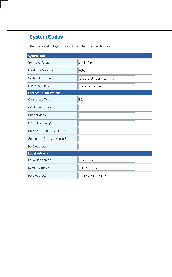
The System Information page displays the System, Internet Configuration, and Local
Network Settings.
Figure 5-2. System Information (Gateway Mode)
The information in this chapter is organized to reflect the structure of the web
management screens for easy reference.
The Configuration pages include the options in the table below. For details on
configuration for each feature, see the corresponding page number.
Note: The displayed pages and settings may differ depending on whether the unit is in
Gateway or Bridge Mode.

5-3
5
Table 5-1. Advanced Settings
Menu Description Mode Page
System Mode 5-4
Operation Mode Sets the operating modes Both 5-4
Network Settings 5-4
WAN Configures settings for the wide area network Gateway 5-4
LAN Sets the unit’s IP address and enables DNS Gateway 5-16
Advanced Routing Configures Static and Dynamic Routing settings Gateway 5-18
Wireless Settings 5-20
Basic Configures wireless transmission method, frequency and
SSID
Both 5-20
Advanced Configures advanced wireless transmission values Both 5-25
Security Configures radio security parameters for the VAP interface Both 5-30
WPS Configures WPS settings Both 5-33
Station List Displays the station list Both 5-35
Firewall 5-35
MAC/IP/Port
Filtering
Configures MAC/IP/Port filtering settings Gateway 5-36
Virtual Server Configures Virtual Server (Port Forwarding) settings Gateway 5-37
DMZ Configures the De-Militarized Zone settings Gateway 5-39
System Security Enables intrusion detection Gateway 5-39
Content Filtering Configures content filtering settings Gateway 5-40
Administration 5-42
System Configures administrator account, password, Date/Time,
Dynamic DNS Settings and Green AP settings.
Both 5-42
Upgrade Firmware Upgrades system software from a local file and enables
provisioning updates
Both 5-44
Configuration Backups and restores the configuration data and restores the
factory defaults
Both 5-45
Status Displays the current system status Both 5-46
Statistics Displays packet statistics Both 5-48
DHCP Clients Displays the DHCP clients table Both 5-49
System Log Displays the system message log Both 5-49
Reboot Reboots the Multimedia Router Both 5-50
System Configuration
5-4
5
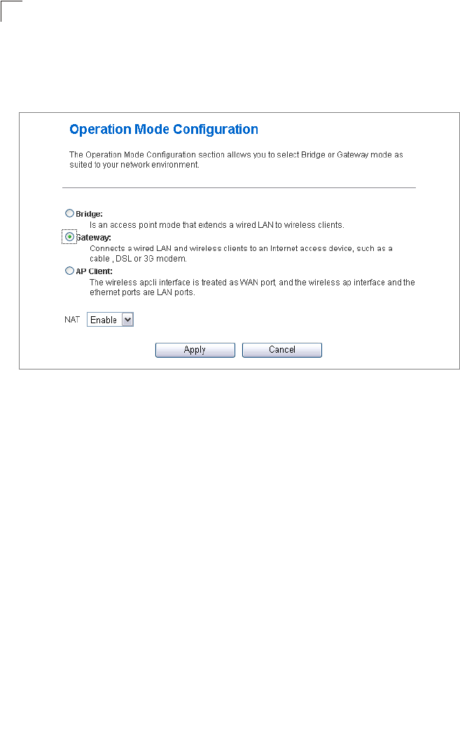
Operation Mode configuration
The Operation Mode Configuration pages allow you to set up the mode suitable for your
network environment.
Figure 5-3. System Information (Gateway Mode)
•Bridge Mode – An access point mode that extends a wired LAN to wireless clients.
•Gateway Mode – A gateway mode that connects a wired LAN and wireless clients to an
Internet access device, such as a cable or DSL modem. This is the factory set default
mode.
•AP Client Mode – Appears only when you’ve selected the Bridge Mode in the Setup
Wizard. The wireless application interface is treated as WAN port, and the wireless ap
interface and the ethernet ports are LAN ports.
Network Settings
The Network Settings pages allow you to manage basic system configuration settings.
Note: In Bridge mode, the Multimedia Router’s Network Settings options are
significantly reduced.
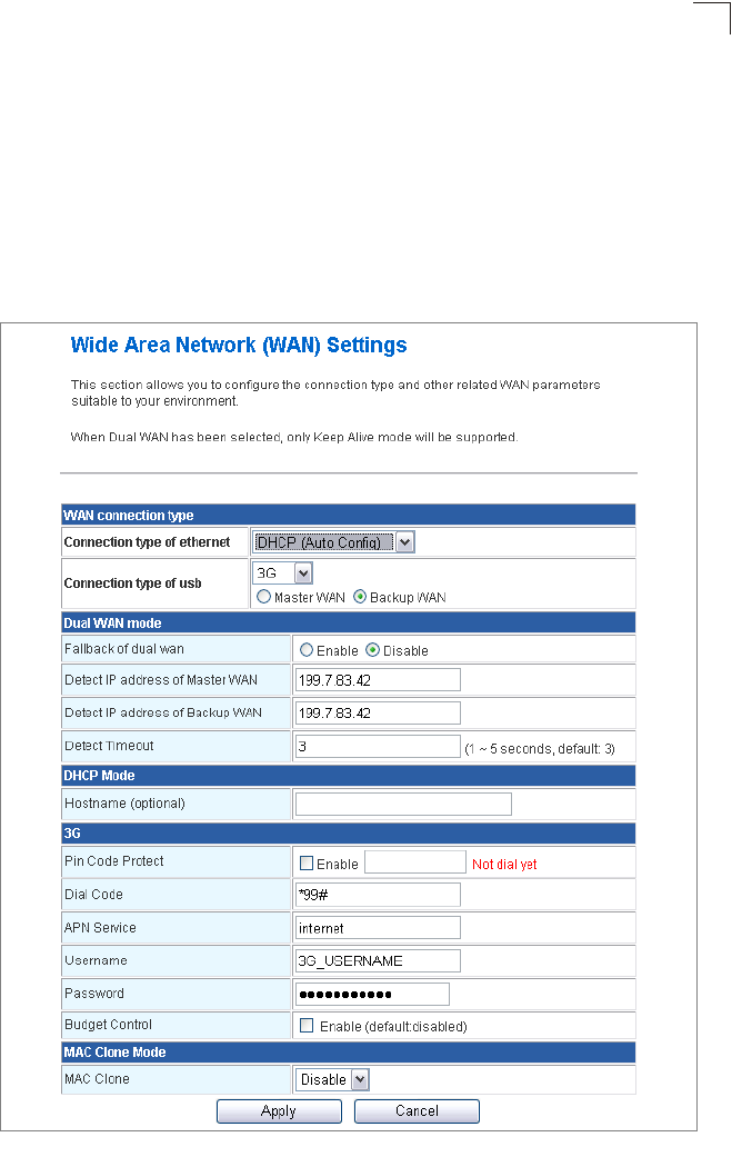
WAN Setting
Specifies the Internet connection parameters. Click on “Network Settings” followed by
“WAN”.
Network Settings
5-5
5
WAN Connection Type — By default, the access point WAN port is configured with
DHCP enabled. After you have network access to the access point, you can use the web
browser interface to modify the initial IP configuration, if needed. The options are Static IP,
DHCP, PPPoE (ADSL), L2TP, PPTP and 3G. Each option changes the parameters
displayed below it. (Default: DHCP).
DHCP
Enables Dynamic Host Configuration Protocol (DHCP) for the WAN port. This setting
allows the Multimedia Router to automatically obtain an IP address from a DHCP server
normally operated by the Internet Service Provider (ISP).
Figure 5-4. WAN Setting - DHCP

System Configuration
5-6
5
•Hostname (Optional) – The hostname of the DHCP client.
•MAC Clone Mode – Some ISPs limit Internet connections to a specified MAC address
of one PC. This setting allows you to manually change the MAC address of the
Multimedia Router's WAN interface to match the PC's MAC address provided to your
ISP for registration. You can enter the registered MAC address manually by typing it in
the boxes provided. Otherwise, connect only the PC with the registered MAC address
to the Multimedia Router, then click the “Fill My MAC” (Default: Disable)
Note: If you are unsure of the PC MAC address originally registered by your ISP, call
your ISP and request to register a new MAC address for your account. Register
the default MAC address of the Multimedia Router.
Network Settings
5-7
5
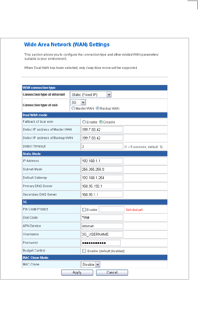
Static IP
Configures a static IP for the WAN port.
Figure 5-5. WAN Setting - Static IP
•IP Address – The IP address of the Multimedia Router. Valid IP addresses consist of
four decimal numbers, 0 to 255, separated by periods.

System Configuration
5-8
5
•Subnet Mask – The mask that identifies the host address bits used for routing to specific
subnets.
•Default Gateway – The IP address of the gateway router for the Multimedia Router,
which is used if the requested destination address is not on the local subnet.
•Primary DNS Server – The IP address of the Primary Domain Name Server on the
network. A DNS maps numerical IP addresses to domain names and can be used to
identify network hosts by familiar names instead of the IP addresses. If you have one or
more DNS servers located on the local network, type the IP addresses in the text fields
provided. Otherwise, leave the addresses as all zeros (0.0.0.0).
•Secondary DNS Server – The IP address of the Secondary Domain Name Server on
the network.
•MAC Clone Mode – Some ISPs limit Internet connections to a specified MAC address
of one PC. This setting allows you to manually change the MAC address of the
Multimedia Router's WAN interface to match the PC's MAC address provided to your
ISP for registration. You can enter the registered MAC address manually by typing it in
the boxes provided. Otherwise, connect only the PC with the registered MAC address
to the Multimedia Router, then click the “Fill My MAC” (Default: Disable)
PPPoE
Enable the Multimedia Router IP address to be assigned automatically from an Internet
service provider (ISP) through an xDSL modem using Point-to-Point Protocol over
Ethernet (PPPoE).
Network Settings
5-9
5
Figure 5-6. WAN Setting - PPPoE
•PPPoE Username – Sets the PPPoE user name for the WAN port.
(Default: pppoe_user; Range: 1~64 characters)

System Configuration
5-10
5
•PPPoE Password – Sets a PPPoE password for the WAN port.
(Default: pppoe_password; Range: 1~32 characters)
•Verify Password – Prompts you to re-enter your chosen password.
•Operation Mode – Selects the operation mode as Keep Alive, On Demand or Manual.
(Default: Keep Alive)
-Keep Alive Mode: The Multimedia Router will periodically check your Internet
connection and automatically re-establish your connection when disconnected.
(Default: 60 seconds)
-On Demand Mode: The maximum length of inactive time the unit will stay connected
to the DSL service provider before disconnecting. This feature only works when
Connect Type is set to “Auto-Connect.” (Default: 5 minutes)
•MAC Clone Mode – Some ISPs limit Internet connections to a specified MAC address
of one PC. This setting allows you to manually change the MAC address of the
Multimedia Router's WAN interface to match the PC's MAC address provided to your
ISP for registration. You can enter the registered MAC address manually by typing it in
the boxes provided. Otherwise, connect only the PC with the registered MAC address
to the Multimedia Router, then click the “Fill My MAC” (Default: Disable)
L2TP
Enables the Layer Two Tunneling Protocol (L2TP) for implementing virtual private
networks. The service is provided in many European countries.
Network Settings
5-11
5
Figure 5-7. WAN Setting - L2TP

System Configuration
5-12
5
•Server IP – Sets the L2TP server IP Address.
(Default: l2tp_server; Range: 1~32 characters)
•Username – Sets the L2TP user name for the WAN port.
(Default: l2tp_user; Range: 1~64 characters)
• Password – Sets a L2TP password for the WAN port. (Default: l2tp_password; Range:
1~32 characters)
•Verify Password – Prompts you to re-enter your chosen password.
•Address Mode – Sets a L2TP network mode. (Default: Static)
•IP Address – Sets the static IP address. (Default: 0.0.0.0, available when L2TP Network
Mode is set to static IP.)
•Subnet Mask – Sets the static IP subnet mask. (Default: 255.255.255.0, available when
L2TP Network Mode is set to static IP.)
•Default Gateway – The IP address of the gateway router for the Multimedia Router,
which is used if the requested destination address is not on the local subnet.
•Operation Mode – Selects the operation mode as Keep Alive, On Demand or Manual.
(Default: Keep Alive)
-Keep Alive Mode: The Multimedia Router will periodically check your Internet
connection and automatically re-establish your connection when disconnected.
(Default: 60 seconds)
-On Demand Mode: The maximum length of inactive time the unit will stay connected
to the DSL service provider before disconnecting. This feature only works when
Connect Type is set to “Auto-Connect.” (Default: 5 minutes)
•MAC Clone Mode – Some ISPs limit Internet connections to a specified MAC address
of one PC. This setting allows you to manually change the MAC address of the
Multimedia Router's WAN interface to match the PC's MAC address provided to your
ISP for registration. You can enter the registered MAC address manually by typing it in
the boxes provided. Otherwise, connect only the PC with the registered MAC address
to the Multimedia Router, then click the “Fill My MAC” (Default: Disable)
PPTP
Enables the Point-to-Point Tunneling Protocol (PPTP) for implementing virtual private
networks. The service is provided in many European countries.
Network Settings
5-13
5
Figure 5-8. WAN Setting - PPTP

System Configuration
5-14
5
•Server IP – Sets a PPTP server IP Address. (Default: pptp_server)
•Username – Sets the PPTP user name for the WAN port.
(Default: pptp_user; Range: 1~64 characters)
•Password – Sets a PPTP password for the WAN port. (Default: pptp_password; Range:
1~32 characters)
•Verify Password – Prompts you to re-enter your chosen password.
•Address Mode – Sets a PPTP network mode. (Default: Static)
•IP Address – Sets the static IP address. (Default: 0.0.0.0, available when PPTP
Network Mode is set to static IP.)
•Subnet Mask – Sets the static IP subnet mask. (Default: 255.255.255.0, available when
PPTP Network Mode is set to static IP.)
•Default Gateway – The IP address of the gateway router for the Multimedia Router,
which is used if the requested destination address is not on the local subnet.
•Operation Mode – Selects the operation mode as Keep Alive, On Demand or Manual.
(Default: Keep Alive)
-Keep Alive Mode: The Multimedia Router will periodically check your Internet
connection and automatically re-establish your connection when disconnected.
(Default: 60 seconds)
-On Demand Mode: The maximum length of inactive time the unit will stay connected
to the DSL service provider before disconnecting. This feature only works when
Connect Type is set to "Auto-Connect". (Default: 5 minutes)
•MAC Clone Mode – Some ISPs limit Internet connections to a specified MAC address
of one PC. This setting allows you to manually change the MAC address of the
Multimedia Router's WAN interface to match the PC's MAC address provided to your
ISP for registration. You can enter the registered MAC address manually by typing it in
the boxes provided. Otherwise, connect only the PC with the registered MAC address
to the Multimedia Router, then click the “Fill My MAC” (Default: Disable)
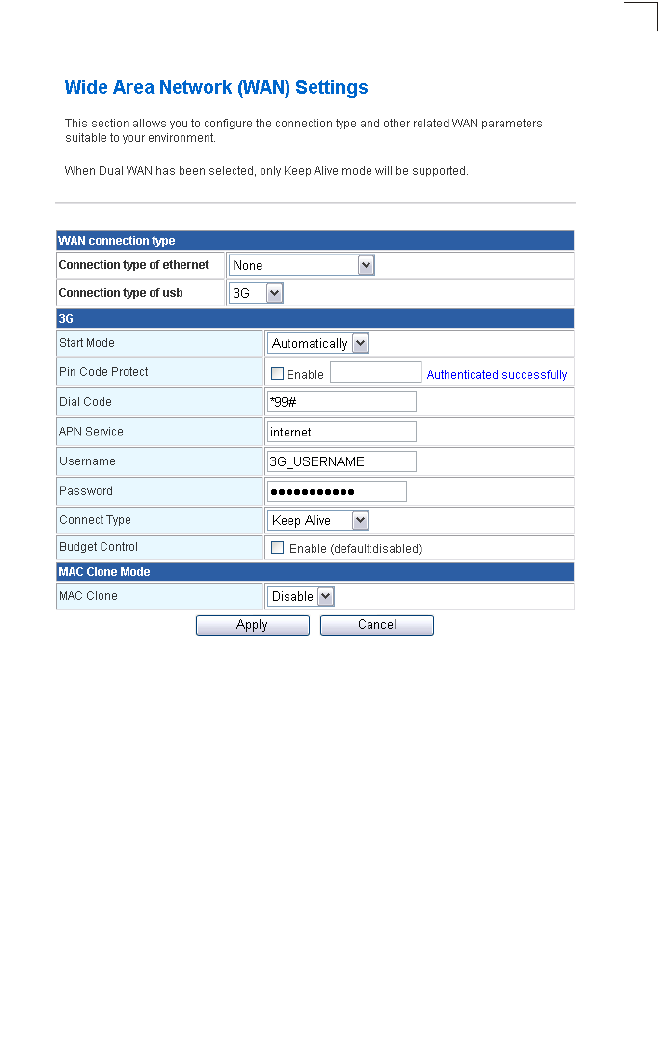
3G
3G technologies enable cellular network operators to offer users a wider range of more
advanced services while achieving greater network capacity through improved spectral
efficiency. Services include wide-area wireless voice telephony, video calls, and
broadband wireless data, all in a mobile environment.
Note: To use this option, you need to first connect a 3G/3.5G USB modem to the USB
port on the back of the unit and have registered an account with a cellular
operator.
Network Settings
5-15
5
Figure 5-9. WAN Setting - 3G
3G – Enables a 3G/3.5G wide-area wireless cellular link on the USB port using an
optional USB modem.
•Start Mode: Select the 3G start mode.
-Automatically: If 3G is selected as primary WAN, when you connect to the 3G
modem, enter the PIN code, and then the wireless router will connect to 3G
Internet service automatically.
-Manually: If the 3G start mode is set to “Manually”, then you can only connect
to the 3G Internet service by pressing the 3G button on the wireless AP/
Router or by using the web interface.
•Pin Code Protect – Enables the use of a PIN code (personal identification number) to
encrypt access to the wireless 3G connection. Some service providers do not require
PIN code authentication. If the PIN code for your 3G/3.5G modem is disabled, disable
this function (Default: Enabled). Specifies a PIN code number that corresponds with that
set on your 3G/3.5G USB modem and displays the status of the 3G connection.
-Not dial yet: Indicates that the PIN code has not been entered or is incorrect.

System Configuration
5-16
5
-Authenticated successfully: Indicates that the 3G connection has
authenticated successfully.
•Dial Code: A dialled access code that connects the USB device to the service provider.
•APN Service: The name that uniquely identifies the cellular operator, access point
name (APN).
•3G Username: The username of the account registered with the service provider.
•3G Password: The password of the account registered with the service provider.
•Connect Type: Selects the connection type as Keep Alive or Auto Connect.
(Default: Auto Connect)
•3G Max Idle Time: The maximum length of inactive time the unit will stay connected to
the DSL service provider before disconnecting. This feature only works when Connect
Type is set to “Auto-Connect.” (Default: 300 seconds)
•Budget Control: You can set a monthly limit on time or the total data. For more details,
please refer to the following table.
3. Basic Wireless Settings – Configures the SSID and sets the wireless security
policy. Click Apply after completing the setup.
LAN Setting
The Multimedia Router must have a valid IP address for management using a web
browser and to support other features. The unit has a default IP address of 192.168.2.1.
You can use this IP address or assign another address that is compatible with your
existing local network. Click on “Network Settings” followed by “LAN.”
By Time By Data
Budget Criterion Specify the amount of time (in
hours) that can be used per month
Specify how much Download/Upload data (in
MBytes) can be transmitted per month
Budget Policy Enable or disable the action “Drop
Current Cellular connection” if
over budget
Enable or disable the action “Disallow New
Cellular connection” if over budget
*Trigger by Limit
Budget
Set the specified % of time limit Set the specified % of time limit
Action taken when the
specified % of time or
data limit is exceeded
Send an E-mail alert Recur every certain minutes
Budget Counter Select the date which the AP/Router resets the budget every month
Network Settings
5-17
5
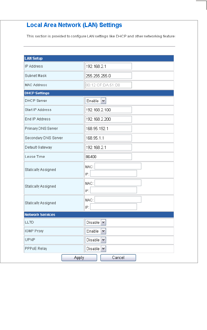
Figure 5-10. LAN Settings (Gateway Mode)
•LAN IP Address – Valid IP addresses consist of four decimal numbers, 0 to 255,
separated by periods. The default setting is 192.168.2.1.
•Subnet Mask – Indicate the local subnet mask. (Default: 255.255.255.0.)
•MAC Address – The shared physical layer address for the Multimedia Router’s LAN
port.
•DHCP Server – Select this option to obtain the IP settings for the access point from a
DHCP (Dynamic Host Configuration Protocol) server. The IP address, subnet mask,

System Configuration
5-18
5
default gateway, and Domain Name Server (DNS) address are dynamically assigned to
the access point by the network DHCP server. (Options: Enable/Disable)
•Start/End IP Address – Specify the start and end IP addresses of a range that the
DHCP server can allocate to DHCP clients. Note that the address pool range is always
in the same subnet as the unit’s IP setting. The maximum clients that the unit can
support is 253.
•Primary DNS Server – The IP address of Domain Name Servers on the network. A
DNS maps numerical IP addresses to domain names and can be used to identify
network hosts by familiar names instead of the IP addresses.
•Secondary DNS Server – The IP address of the Secondary Domain Name Server on
the network.
•Default Gateway – The default gateway is the IP address of the router for the
Multimedia Router, which is used if the requested destination address is not on the local
subnet.
•Lease Time – Select a time limit for the use of an IP address from the IP pool. When
the time limit expires, the client has to request a new IP address. The lease time is
expressed in seconds. (Default: 86400 seconds; Range: 60~864000 seconds)
•Statically Assigned – Up to three devices with specific MAC addresses can be
assigned static IP addresses. That is, the DHCP server always assigns these devices
the same IP addresses.
•LLTD – Link Layer Topology Discovery (LLTD) is a Microsoft proprietary discovery
protocol which can be used for both wired and wireless networks. (Options: Disable/
Enable, Default: Disable)
•IGMP Proxy – Enables IGMP proxy on the Multimedia Router. (Options: Disable/
Enable, Default: Disable)
•UPNP – Allows the device to advertise its UPnP capabilities. (Default: Disable)
•PPPoE Relay – When enabled, the Multimedia Router will forward PPPoE messages
to clients. Clients are then able to connect to the PPPoE service through the WAN port.
(Options: Disable/Enable, Default: Disable)
Advanced Routing
Routing setup allows a manual method to set up routing between networks. The network
administrator configures static routes by entering routes directly into the routing table.
Static routing has the advantage of being predictable and easy to configure.
Advanced Routing Settings
This screen is used to manually configure static routes to other IP networks, subnetworks,
or hosts. Click “Network Settings” followed by “Advanced Routing”. (Maximum 32 entries
are allowed.)
Network Settings
5-19
5
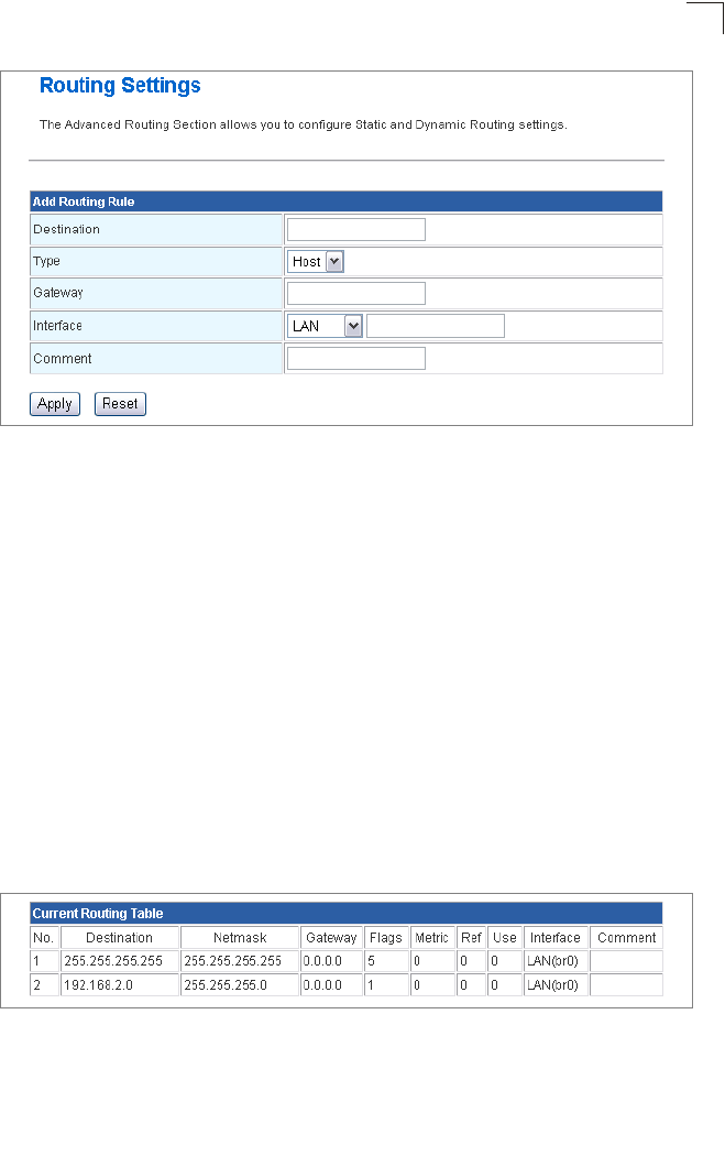
Figure 5-11. Advanced Route (Gateway Mode)
•Destination – A destination network or specific host to which packets can be routed.
•Type – Defines the type of destination. (Options: Host/Net, Default: Host)
•Gateway – The IP address of the router at the next hop to which matching frames are
forwarded.
•Interface – The selected interface to which a static routing subnet is to be applied.
•Comment – Enters a useful comment to help identify this route.
Routing Table
This page displays the information necessary to forward a packet along the best path
toward its destination. Each packet contains information about its origin and destination.
When a packet is received, a network device examines the packet and matches it to the
routing table entry providing the best match for its destination. The table then provides the
device with instructions for sending the packet to the next hop on its route across the
network.
Note: The Routing Table is only available when the Multimedia Router is set to Gateway
Mode.
Figure 5-12. Routing Table (Gateway Mode)
• Destination – Displays all destination networks or specific hosts to which packets can
be routed.
• Netmask – Displays the subnetwork associated with the destination.

System Configuration
5-20
5
•Gateway – Displays the IP address of the router at the next hop to which matching
frames are forwarded.
•Flags – Possible flags identify as below
- 0: reject route
- 1: route is up
- 3: route is up, use gateway
- 5: route is up, target is a host
- 7: route is up, use gateway, target is a host
•Metric – A number used to indicate the cost of the route so that the best route, among
potentially multiple routes to the same destination, can be selected.
•Ref – Number of references to this route.
•Use – Count of lookups for the route.
•Interface – Interface to which packets for this route will be sent.
• Comment – Displays a useful comment to identify the routing rules.
Wireless Settings
The IEEE 802.11n interfaces include configuration options for radio signal characteristics
and wireless security features.
The Multimedia Router can operate in five modes, mixed 802.11b/g/n, mixed 802.11b/g,
802.11b only and 802.11g only. Also note that 802.11g is backward compatible with
802.11b, and 802.11n is backward compatible with both 802.11b/g at slower data transmit
rates.
Each radio supports two virtual access point (VAP) interfaces, referred to as WLAN1 and
WLAN2. Each VAP functions as a separate access point, and can be configured with its
own Service Set Identification (SSID) and security settings. However, most radio signal
parameters apply to both VAP interfaces. The configuration options are nearly identical,
and are therefore both covered in this section of the manual.
Traffic to specific VAPs can be segregated based on user groups or application traffic.
Both VAPs can have up to 64 wireless clients, whereby the clients associate with these
VAPs the same as they would with a physical access point.
Note: The radio channel settings for the access point are limited by local regulations,
which determine the number of channels that are available. See “Specifications”
on page B-1 for additional information on the maximum number channels
available.
Basic Settings
The Basic Setting page allows you to enable the wireless interface, select which radio
mode to use, choose the transmit frequency and configure SSIDs.
Click on “Wireless Settings,” followed by “Basic”.
Note: There are several variables to consider when selecting a radio mode that make it
fully functional. Simply selecting the mode you want is not enough to ensure full
compatibility for that mode. Information on these variables may be found in the
Advanced Setting section.
Wireless Settings
5-21
5
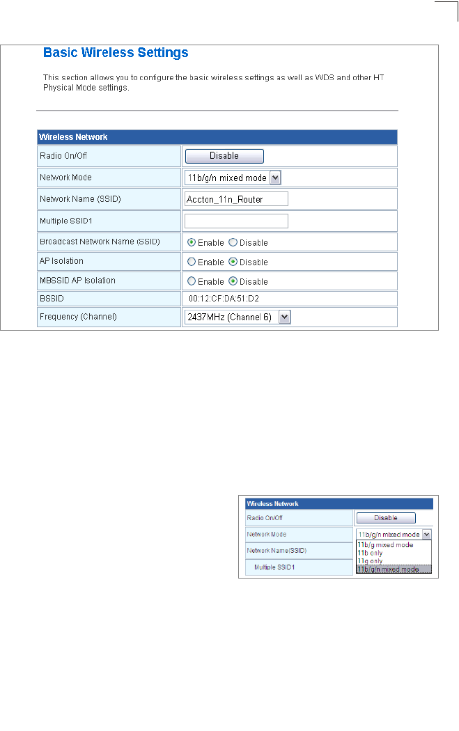
Figure 5-13. Basic Wireless Settings
•Radio On/Off – Enables or Disable the radio. (Default: Enable)
•Network Mode – Defines the radio mode for the VAP interface.
(Default: 802.11b/g/n Mixed)
Note: Enabling the Multimedia Router to communicate with 802.11b/g clients in both
802.11b/g/n Mixed and 802.11n modes also requires that HT Operation in the
Advanced Settings menu be set to Mixed. Setting HT Operation to Green Field is
exclusive for 802.11n client communication only and prevents 802.11 b/g
communication.
-802.11b/g Mixed: Both 802.11b and
802.11g clients can communicate with the
Multimedia Router (up to 108 Mbps), but
data transmission rates may be slowed to
compensate for 802.11b clients. Any
802.11n clients will also be able to
communicate with the Multimedia Router,
but they will be limited to 802.11g protocols and data transmission rates.
-802.11b only: All 802.11b, 802.11g, and 802.11n clients will be able to communicate
with the Multimedia Router, but the 802.11g and 802.11n clients will be limited to
802.11b protocols and data transmission rates (up to 11 Mbps).
-802.11g only: Both 802.11g and 802.11n clients will be able to communicate with the
Multimedia Router, but the 802.11n clients will be limited to 802.11g protocols and
data transmission rates (up to 54 Mbps). Any 802.11b clients will not be able to
communicate with the Multimedia Router.
System Configuration
5-22
5
-802.11b/g/n Mixed: All 802.11b/g/n clients can communicate with the Multimedia
Router (up to 300 Mbps), but data transmission rates may be slowed to compensate
for 802.11b/g clients.
•Network Name (SSID) – The name of the wireless network service provided by the
VAP. Clients that want to connect to the network must set their SSID to the same as that
of the VAP interface. (Default: “Accton_11n_Router”; Range: 1-32 characters)
-Multiple SSID – The number of wireless network interfaces (SSIDs) supported on the
device.
•Broadcast Network Name (SSID) – The Multimedia Router will broadcast its SSID.
•AP Isolation – The Multimedia Router will isolate wireless clients in order to protect
them. Normally for users who are at hotspots.
•MBSSID AP Isolation – The Multimedia Router will isolate wireless clients from
different SSID.
•BSSID – The identifier (MAC address) of a Multimedia Router in a Basic Service Set
(BSS) network.
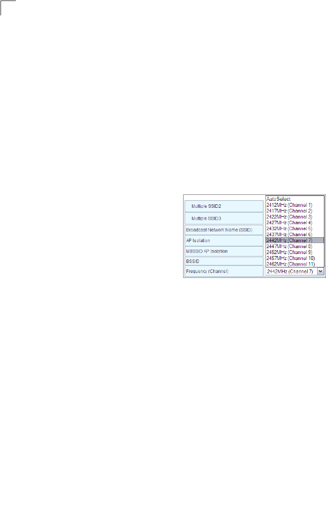
•WLAN Frequency – The radio channel that
the Multimedia Router uses to communicate
with wireless clients. When multiple access
points are deployed in the same area, set the
channel on neighboring access points at
least five channels apart to avoid
interference with each other. For example,
you can deploy up to three access points in
the same area using channels 1, 6, 11. Note
that wireless clients automatically set the channel to the same as that used by the
Multimedia Router to which it is linked. Selecting Auto Select enables the Multimedia
Router to automatically select an unoccupied radio channel.
Wireless Distribution System (WDS)
The WLAN1 radio interface can be configured to operate in a mode that allows it to
forward traffic directly to other access point units. To set up links between access point
units, you must configure the Wireless Distribution System (WDS) forwarding table by
specifying the wireless MAC address of all units to which you want to forward traffic.
Traffic forwarded to WDS links is automatically converted to 802.11 four-address format
frame. This uses the MAC addresses of the station and that of the AP connected to it on
the transmitting LAN, and the MAC addresses of the AP functioning as a wireless
repeater/bridge and that of the station connected to it on a neighboring LAN in the 802.11
frame header. Ethernet traffic follows a three-address format that is reconstructed for
WDS transmission. The Multimedia Router will reconstruct the frame format upon
receiving and transmission using the criteria of the receiving and forwarding port location
and whether it is Ethernet or wireless in type.
Note: The Multimedia Router does not support the spanning tree algorithm. WDS links
should be configured appropriately to avoid causing loops on the network.
Up to four WDS links can be specified for each unit in the WDS network.
The WDS link can be configured in the following combinations:
Wireless Settings
5-23
5
1. All units are configured as Gateway Mode
2. Units can be configured as Gateway Mode and Bridge Mode combinations.
(ex: 2 units for Gateway Mode and 2 units for Bridge Mode)
3. All units are configured as Bridge Mode
When both units are set to Gateway Mode, be sure to check these settings:
• Be sure each unit is configured with a different LAN IP address.
• Be sure that only one unit has Internet access on its WAN port.
• Be sure the DHCP server is enabled only on one unit. If one unit is providing Internet
access, enable the DHCP server on that unit.
Note: WDS Settings only apply to WLAN1. WLAN2 is pre-configured to Bridge mode
unless WLAN1 is configured to act as a bridge, in which case WLAN2 is disabled.
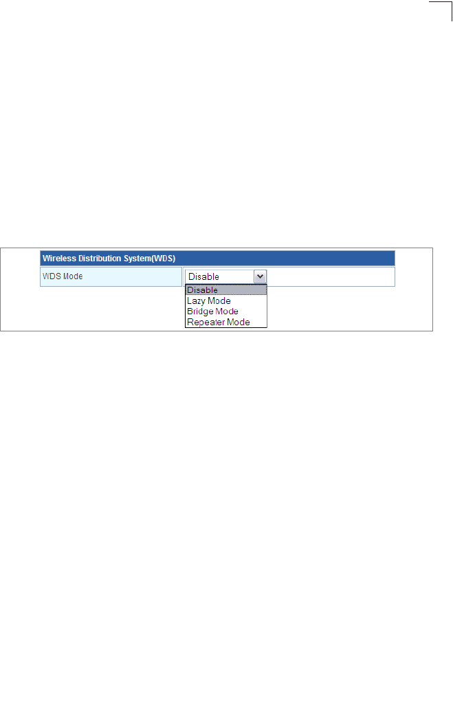
Figure 5-14. WDS Settings
WDS Setting — Configures WDS related parameters. Up to four MAC addresses can be
specified for each unit in the WDS network. WDS links may either be manually configured
(Bridge and Repeater modes) or auto-discovered (Lazy mode).
•WDS Mode – Selects the WDS mode of WLAN1. (Options: Disable/Lazy/Bridge/
Repeater. Default: Disable)
-Disable: WDS is disabled.
-Lazy: Operates in an automatic mode that detects and learns WDS peer addresses
from received WDS four-address format frame packets, without the need to configure
a WDS MAC list entry. This feature allows the Multimedia Router to associate with
other Multimedia Routers in the network and use their WDS MAC list. In Lazy mode
the Multimedia Router sends a beacon.
Note: At least one unit can not be configured in lazy mode.
-Bridge: Operates as a standard bridge that forwards traffic between WDS links (links
that connect to other AP/wireless bridges, or units in Repeater or Lazy mode) and an
Ethernet port. Only data destined for stations which are known to be on the peer
Ethernet link, multicast data or data with unknown destinations, need to be forwarded
through the WDS link. The Bridge mode does not transmit a beacon, unlike the other
three modes. In this mode the Multimedia Router may also function as a repeater.
Note: Enabling “Bridge” mode disables WLAN2.
-Repeater: Operates as a wireless repeater, extending the range for remote wireless
clients and connecting them to an AP connected to the wired network. WDS peers
must be registered with the Multimedia Router. Repeater mode also supports the dual
System Configuration
5-24
5
capability of the VAP functioning as an AP. In this mode, traffic is not forwarded to the
Ethernet port from the radio interface. In Repeater mode the Multimedia Router
transmits a beacon.
Note: WDS settings may only be configured for WLAN1, See “Wi-Fi Protected Setup
(WPS)” on page 5-33. WLAN2 only operates as an access point service.
Note: Configuring WLAN1 to operate in WDS “Bridge” mode automatically disables
WLAN2.
HT Physical Mode Settings
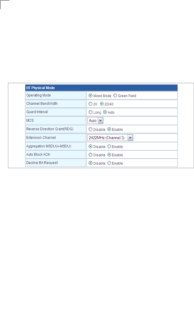
Figure 5-15. HT Physical Mode Settings
•HT Operation Mode – Packets from 802.11n clients are referred to as High Throughput
(HT) Greenfield packets, in other words packets that can be transmitted at rates of up
to 300 Mbps assuming that HT Channel Bandwidth is set to 20/40Mhz, see HT Channel
Bandwidth next page.
Note: Some 802.11n wireless clients may be capable of transmission rates of up to
600 Mbps, however the Multimedia Router will only be able to connect to them at
a maximum transmission rate of 150 Mbps.
• 802.11b/g packets are referred to as non-HT packets, being transmitted at lower
throughput rates. HT mixed format frames contain a preamble compatible with the
non-HT receivers. HT Greenfield frames do not contain a non-HT compatible part.
Support for HT Greenfield format is optional. An HT station that does not support the
reception of an HT Greenfield format frame must be able to detect that an HT Greenfield
format frame is an HT transmission (as opposed to a non-HT transmission). In this case
the receiver must decode the high throughput signal (HT-SIG) in the packet header and
determine if the HT-SIG cyclic redundancy check (CRC) passes. (Default: Mixed)
•HT Channel Bandwidth – The Multimedia Router provides a channel bandwidth of 40
MHz by default giving an 802.11g connection speed of 108 Mbps (sometimes referred
to as Turbo Mode) and a 802.11n connection speed of up to 150 Mbps. Setting the HT
Channel Bandwidth to 20 MHz slows connection speed for 802.11g and 802.11n to 54
Wireless Settings
5-25
5
Mbps and 74 Mbps respectively and ensures backward compliance for slower 802.11b
devices. (Default: 20/40MHz)
•Guard Interval – The guard interval between symbols helps receivers overcome the
effects of multipath delays. When you add a guard time, the back portion of useful signal
time is copied and appended to the front. (Default: Auto)
•MCS – The Modulation and Coding Scheme (MCS) is a value that determines the
modulation, coding and number of spatial channels. (Options: value [range] = 0~7 (1 Tx
Stream), 8~15 (2 TxStream), 32 and auto (33). Default: auto)
•Reverse Direction Grant (RDG) – When enables Reverse Direction Grant, the
Multimedia Router can reduce the transmitted data packet collision by using the reverse
direction protocol. During TXOP (Transmission Opportunity) period, the receiver could
use remaining transmission time to transmit data to a sender. The RDG improves
transmission performance and scalability in a wireless environment.
•Extension Channel – When 20/40MHz channel bandwidth has been set, the extension
channel option will be enabled. The extension channel will allow you to get extra
bandwidth. (Options: 2417MHz/Channel 2, 2457MHz/Channel 10. Default: 2457MHz/
Channel 10.)
•Aggregate MSDU (A-MSDU) – This option enables Mac Service Data Unit (MSDU)
aggregation. (Default: Disable)
•Auto Block ACK – Select to block ACK (Acknowledge Number) or not during data
transferring.
•Decline BA Request – Select to reject peer BA-Request or not.
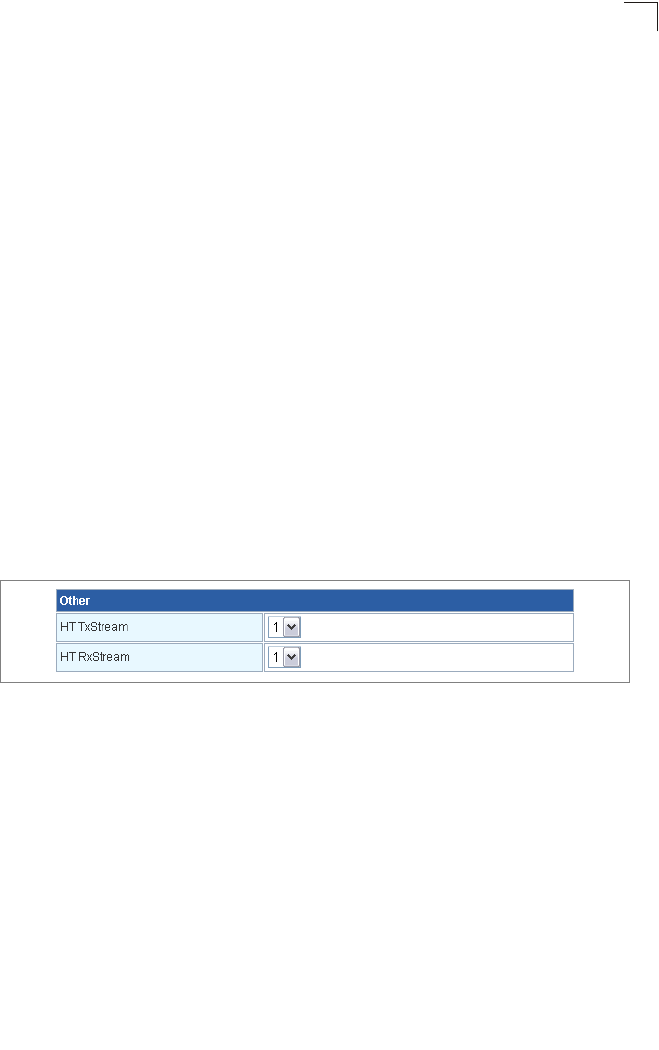
Other HT Settings
Figure 5-16. HT Physical Mode Settings
•HT TxStream – HT means High Throughput. The number of HT TxStream means how
many antennas will transmit data simultaneously. (Options: 1 or 2. Default: 2)
•HT RxStream – The number of HT RxStream means how many antennas will receive
data simultaneously. (Options: 1 or 2. Default: 2)
Advanced Wireless Settings
The Advanced Setting page allows you to configure the more advanced radio settings,
many of which are enabled by default.
Click “Wireless Settings” followed by “Advanced”.
System Configuration
5-26
5
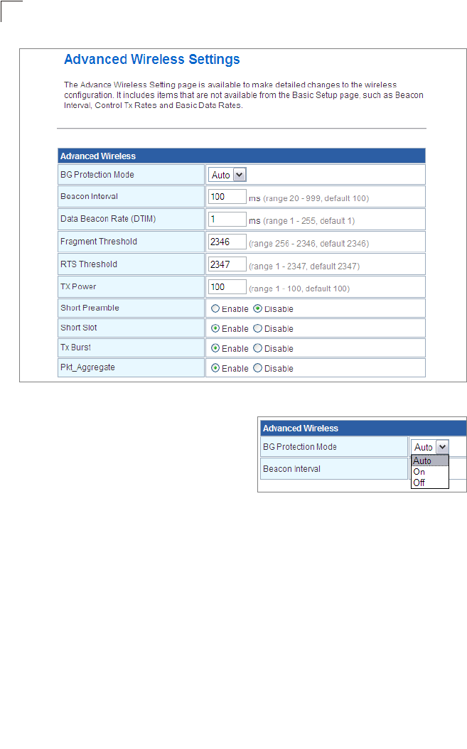
Figure 5-17. Advanced Wireless Settings
•BG Protection – Enables a backward
compatible protection system for
802.11b clients. There are three modes.
(Default: Auto):
-Auto: The Multimedia Router enables its
protection mechanism for 802.11b
clients when they are detected in the network. When 802.11b clients are not detected,
the protection mechanism is disabled.
-On: Forces the unit to always use protection for 802.11b clients, whether they are
detected in the network or not.
-Off: Forces the unit to never use protection for 802.11b clients. This prevents 802.11b
clients from connecting to the network.
Note: Enabling “On” b/g Protection can slow throughput for 802.11g/n clients by as
much as 50%.
•Beacon Interval – The rate at which beacon signals are transmitted from the access
point. The beacon signals allow wireless clients to maintain contact with the access
point. They may also carry power-management information. (Range: 20-999 TUs;
Default: 100 TUs)
•Data Beacon Rate (DTIM) – The rate at which stations in sleep mode must wake up to
receive broadcast/multicast transmissions. Known also as the Delivery Traffic Indication
Map (DTIM) interval, it indicates how often the MAC layer forwards broadcast/multicast
traffic, which is necessary to wake up stations that are using Power Save mode. The

Wireless Settings
5-27
5
default value of 2 indicates that the access point will save all broadcast/multicast frames
for the Basic Service Set (BSS) and forward them after every second beacon. Using
smaller DTIM intervals delivers broadcast/multicast frames in a more timely manner,
causing stations in Power Save mode to wake up more often and drain power faster.
Using higher DTIM values reduces the power used by stations in Power Save mode, but
delays the transmission of broadcast/multicast frames. (Range: 1-255 beacons; Default:
1 beacon)
•Fragment Threshold – Configures the minimum packet size that can be fragmented
when passing through the access point. Fragmentation of the PDUs (Package Data
Unit) can increase the reliability of transmissions because it increases the probability of
a successful transmission due to smaller frame size. If there is significant interference
present, or collisions due to high network utilization, try setting the fragment size to send
smaller fragments. This will speed up the retransmission of smaller frames. However, it
is more efficient to set the fragment size larger if very little or no interference is present
because it requires overhead to send multiple frames. (Range: 256-2346 bytes; Default:
2346 bytes)
•RTS Threshold – Sets the packet size threshold at which a Request to Send (RTS)
signal must be sent to a receiving station prior to the sending station starting
communications. The access point sends RTS frames to a receiving station to negotiate
the sending of a data frame. After receiving an RTS frame, the station sends a CTS
(clear to send) frame to notify the sending station that it can start sending data. If the
RTS threshold is set to 0, the access point always sends RTS signals. If set to 2347, the
access point never sends RTS signals. If set to any other value, and the packet size
equals or exceeds the RTS threshold, the RTS/CTS (Request to Send / Clear to Send)
mechanism will be enabled. The access points contending for the medium may not be
aware of each other. The RTS/CTS mechanism can solve this “Hidden Node Problem.”
(Range: 0-2347 bytes)
•TX Power – Adjusts the power of the radio signals transmitted from the access point.
The higher the transmission power, the farther the transmission range. Power selection
is not just a trade off between coverage area and maximum supported clients. You also
have to ensure that high-power signals do not interfere with the operation of other radio
devices in the service area.
•Short Preamble – Enables the length of the signal preamble that is used at the start of
a data transmission. (Default: Disable)
•Short Slot – Sets the basic unit of time the Multimedia Router’s uses for calculating
waiting times before data is transmitted. Enabling a short slot time can increase data
throughput on the Multimedia Router, but requires that all clients can support a short slot
time (that is, 802.11g-compliant clients must support a short slot time). (Default: Enable)
•Tx Burst – Enables data transmission bursting to boost throughput for high data
transmissions. (Default: Enable)
•Pkt_aggregation – Enables grouping together of some packets and sending them
together to boost bandwidth. (Default: Enable)
System Configuration
5-28
5
Configuring Wi-Fi Multimedia
Wireless networks offer an equal opportunity for all devices to transmit data from any type
of application. Although this is acceptable for most applications, multimedia applications
(with audio and video) are particularly sensitive to the delay and throughput variations that
result from this equal opportunity wireless access method. For multimedia applications to
run well over a wireless network, a Quality of Service (QoS) mechanism is required to
prioritize traffic types and provide an enhanced opportunity wireless access method. The
access point implements QoS using the Wi-Fi Multimedia (WMM) standard. Using WMM,
the access point is able to prioritize traffic and optimize performance when multiple
applications compete for wireless network bandwidth at the same time. WMM employs
techniques that are a subset of the developing IEEE 802.11e QoS standard and it enables
the access point to inter operate with both WMM enabled clients and other devices that
may lack any WMM functionality.
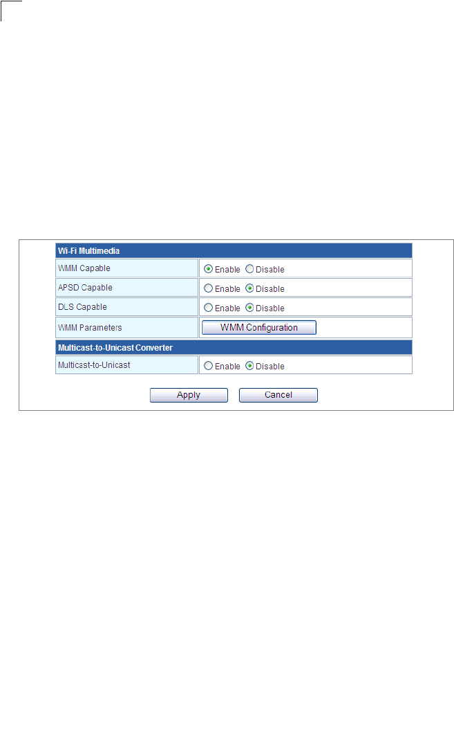
Figure 5-18. Wi-Fi Multimedia Settings
•WMM Capable – Wi-Fi Multimedia (WMM), also known as Wireless Multimedia
Extensions (WME), is a Wi-Fi Alliance interoperability certification. It provides basic
Quality of Service (QoS) features for IEEE 802.11 wireless network. Enabling WMM
support provides prioritization of Wi-Fi data packets on four categories voice, video, best
effort, and background. (Default: Enabled)
•APSD Capable – Auto Power Save Delivery is used for saving power consumption.
APSD allows a longer beacon interval until the traffic arrives. (Default: Disable., See
“Beacon Interval” on page 5-26)
•DLS Capable – The Direct Link Setup (DLS) allows all clients transfer data more
effectively. When enables DLS, the Multimedia Router will all clients on this unit to
establish directly connection and speed up the data transmission, especially for
multimedia data files. (Default: Disable)
•WMM Parameters – Display the WMM Parameters.
Wireless Settings
5-29
5
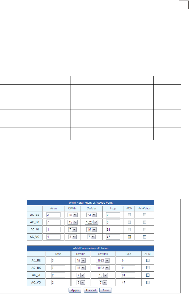
Access Categories – WMM defines four access categories (ACs): voice, video, best
effort, and background. These categories correspond to traffic priority levels and are
mapped to IEEE 802.1D priority tags (see Table 5-1). The direct mapping of the four ACs
to 802.1D priorities is specifically intended to facilitate inter operability with other wired
network QoS policies. While the four ACs are specified for specific types of traffic, WMM
allows the priority levels to be configured to match any network-wide QoS policy. WMM
also specifies a protocol that access points can use to communicate the configured traffic
priority levels to QoS-enabled wireless clients.
WMM Operation — WMM uses traffic priority based on the four ACs; Voice, Video, Best
Effort, and Background. The higher the AC priority, the higher the probability that data is
transmitted. When the access point forwards traffic, WMM adds data packets to four
independent transmit queues, one for each AC, depending on the 802.1D priority tag of
the packet. Data packets without a priority tag are always added to the Best Effort AC
queue. From the four queues, an internal “virtual” collision resolution mechanism first
selects data with the highest priority to be granted a transmit opportunity. Then the same
collision resolution mechanism is used externally to determine which device has access
to the wireless medium.
Figure 5-19. WMM Parameters
Table 5-1. WMM Access Categories
Access Category WMM Designation Description 802.1D Tags
AC_VO (AC3) Voice Highest priority, minimum delay. Time-sensitive
data such as VoIP (Voice over IP) calls.
7, 6
AC_VI (AC2) Video High priority, minimum delay. Time-sensitive data
such as streaming video.
5, 4
AC_BE (AC0) Best Effort Normal priority, medium delay and throughput.
Data only affected by long delays. Data from
applications or devices that lack QoS capabilities.
0, 3
AC_BK (AC1) Background Lowest priority. Data with no delay or throughput
requirements, such as bulk data transfers.
2, 1

System Configuration
5-30
5
WMM Acknowledge Policy – By default, all wireless data transmissions require the
sender to wait for an acknowledgement from the receiver. WMM allows the
acknowledgement wait time to be turned off for each Access Category (AC). Although this
increases data throughput, it can also result in a high number of errors when traffic levels
are heavy. (Default: Acknowledge)
WMM BSS Parameters – These parameters apply to the wireless clients.
WMM AP Parameters – These parameters apply to the access point.
•logCWMin (Minimum Contention Window) – The initial upper limit of the random backoff
wait time before wireless medium access can be attempted. The initial wait time is a
random value between zero and the CWMin value. Specify the CWMin value in the
range 0-15 microseconds. Note that the CWMin value must be equal or less than the
CWMax value.
•logCWMax (Maximum Contention Window) – The maximum upper limit of the random
backoff wait time before wireless medium access can be attempted. The contention
window is doubled after each detected collision up to the CWMax value. Specify the
CWMax value in the range 0-15 microseconds. Note that the CWMax value must be
greater or equal to the CWMin value.
•AIFS (Arbitration Inter-Frame Space) – The minimum amount of wait time before the
next data transmission attempt. Specify the AIFS value in the range 0-15 microseconds.
•TXOP Limit (Transmit Opportunity Limit) – The maximum time an AC transmit queue
has access to the wireless medium. When an AC queue is granted a transmit
opportunity, it can transmit data for a time up to the TxOpLimit. This data bursting greatly
improves the efficiency for high data-rate traffic. Specify a value in the range 0-65535
microseconds.
•Admission Control – The admission control mode for the access category. When
enabled, clients are blocked from using the access category. (Default: Disable)
WLAN Security
The Multimedia Router’s wireless interface is configured by default as an “open system,”
which broadcasts a beacon signal including the configured SSID. Wireless clients with a
configured SSID of “ANY” can read the SSID from the beacon, and automatically set their
SSID to allow immediate connection to the wireless network.
To improve wireless network security, you have to implement two main functions:
•Authentication – It must be verified that clients attempting to connect to the network
are authorized users.
•Traffic Encryption – Data passing between the unit and clients must be protected from
interception and eavesdropping.
For a more secure network, the Multimedia Router can implement one or a combination
of the following security mechanisms:
• Wired Equivalent Privacy (WEP)
The security mechanisms that may be employed depend on the level of security required,
the network and management resources available, and the software support provided on
wireless clients. Click on “Wireless Settings,” followed by “Security”.
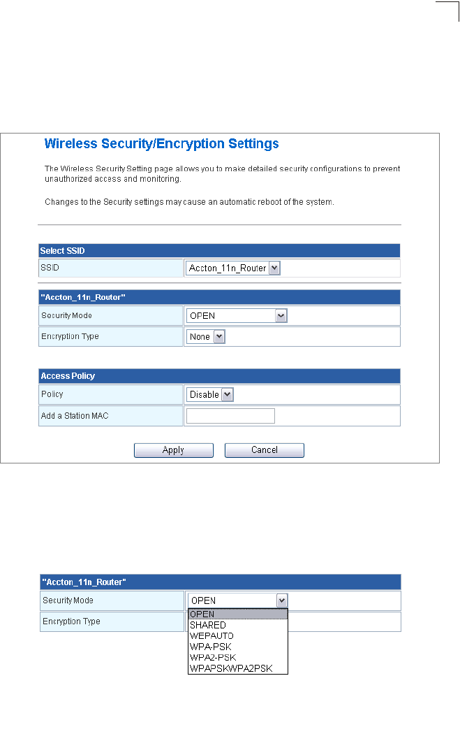
Wireless Settings
5-31
5
Security
The Multimedia Router supports two virtual access point (VAP) interfaces referred to as
WLAN1 and WLAN2. Each VAP functions as a separate access point, and can be
configured with its own security settings.
Click on “Wireless Settings,” followed by “Security”.
Figure 5-20. Wireless Security Settings
Security Settings — The security settings determine the security mode and enable WEP
keys.
•Security Mode – Configures the security mode used by clients.
(WLAN1/WLAN2 Defaults: Open)
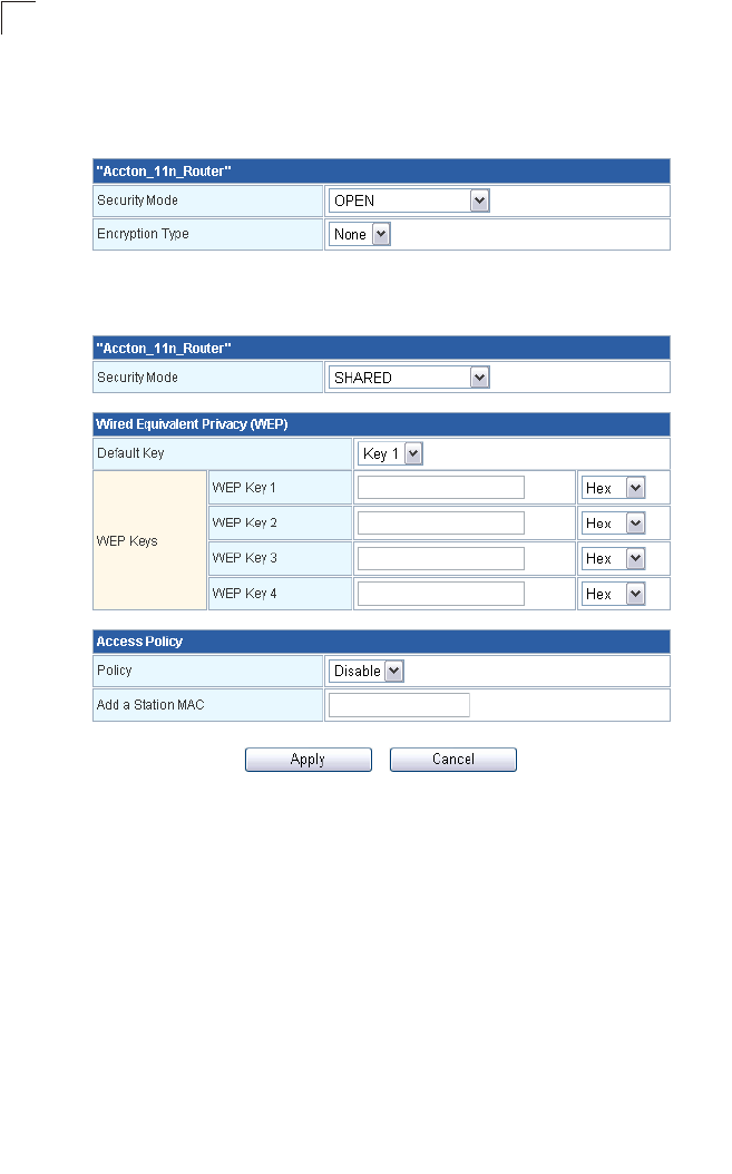
System Configuration
5-32
5
-Open: Open-system authentication accepts any client attempting to connect the
Multimedia Router without verifying its identity. In this mode the default encryption
type is "None".
-Shared: The shared-key approach uses Wired Equivalent Privacy (WEP) to verify
client identity by distributing a shared key to clients before attempting authentication.
-WEP Auto: Allows WLAN clients to associate using Open-WEP (uses WEP for
encryption only) or Shared-WEP (uses WEP for authentication and encryption). If
enabled, you must configure at least one key for the VAP interface and all its clients.
Wired Equivalent Privacy (WEP) provides a basic level of security, preventing
unauthorized access to the network and encrypting data transmitted between
wireless clients and the Multimedia Router. WEP uses static shared keys
(fixed-length hexadecimal or alphanumeric strings) that are manually distributed to
all clients that want to use the network.
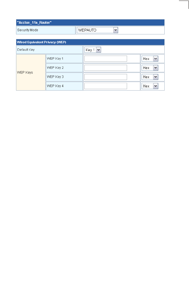
Wireless Settings
5-33
5
-WPA-PSK/WPA2-PSK: The WPA or WPA2 mode uses a common password phrase,
called a Pre-Shared Key, that must be manually distributed to all clients that want to
connect to the network. Specify a key as an easy-to-remember form of letters and
numbers. The WPA Preshared Key can be input as ASCII string (8-63 characters) or
Hexadecimal format (length is 64). All wireless clients must be configured with the
same key to communicate with the VAP interface.
Wi-Fi Protected Setup (WPS)
Wi-Fi Protected Setup (WPS) is designed to ease installation and activation of security
features in wireless networks. WPS has two basic modes of operation, Push-button
Configuration (PBC) and Personal Identification Number (PIN). The WPS PIN setup is
optional to the PBC setup and provides more security. The WPS button in the Tools >
Network Setting > Router Setting On-Screen Display (OSD) menu can be selected at any
time to allow a single device to easily join the network.
Note: WPS settings only apply to WLAN1.
The WPS Settings page includes configuration options for setting WPS device PIN codes
and activating the virtual WPS button.
Click on “Wireless Settings,” followed by ‘WPS”.
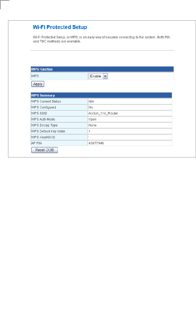
System Configuration
5-34
5
Figure 5-21. WPS Settings
WPS Function — Enables WPS, locks security settings, and refreshes WPS
configuration information.
•WPS – Enables WPS. (Default: Disable)
WPS Summary – Provides detailed WPS statistical information.
•WPS Current Status – Displays if there is currently any WPS traffic connecting to the
Multimedia Router. (Options: Start WSC Process; Idle; Default: Idle)
•WPS Configured – States if WPS for wireless clients has been configured for this
device. (Default: no)
•WPS SSID – The service set identifier for WLAN1. (Default: Accton_11n_Router)
•WPS Auth Mode – The method of authentication used. (Default: Open)
•WPS Encryp Type – The encryption type used for WLAN1. (Default: None)
•WPS Default Key Index – Displays the WEP default key (1~4).
•WPS Key (ASCII) – Displays the WPS security key (ASCII) which can be used to ensure
the security of the wireless network.
•AP PIN – Displays the PIN Code for the Multimedia Router. The default is exclusive for
each unit. (Default: 61461345)
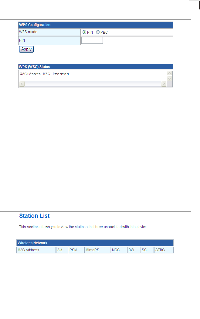
Firewall
5-35
5
Figure 5-22. WPS Progress Settings
WPS Configuration — Configures WPS settings for the Multimedia Router.
•WPS Mode – Selects between methods of broadcasting the WPS beacon to network
clients wanting to join the network:
-PIN: The Multimedia Router, along with other WPS devices, such as notebook PCs,
cameras, or phones, all come with their own eight-digit PIN code. When one device,
the WPS enrollee, sends a PIN code to the Multimedia Router, it becomes the WPS
registrar. After configuring PIN-Code information you must press “Apply” to send the
beacon, after which you have up to two minutes to activate WPS on devices that need
to join the network.
-PBC: This has the same effect as tapping the WPS button in Tools > Network Setting
> Router Setting On-Screen Display (OSD) menu. After checking this option and
clicking “Apply”, you have up to two minutes to activate WPS on devices that need to
join the network.
Station List
Display the station information which associated to this Multimedia Router.
Figure 5-23. Station List
Firewall
The Multimedia Router provides extensive firewall protection by restricting connection
parameters to limit the risk of intrusion and defending against a wide array of common
hacker attacks.
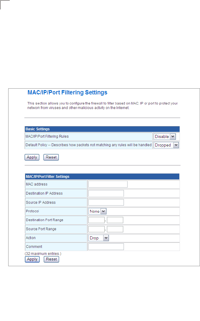
System Configuration
5-36
5
MAC/IP/Port Filtering
MAC/IP/Port filtering restricts connection parameters to limit the risk of intrusion and
defends against a wide array of common hacker attacks. IP/Port filtering allows the unit to
permit, deny or proxy traffic through its MAC addresses, IP addresses and ports.
The Multimedia Router allows you define a sequential list of permit or deny filtering rules
(up to 32). This device tests ingress packets against the filter rules one by one. A packet
will be accepted as soon as it matches a permit rule, or dropped as soon as it matches a
deny rule. If no rules match, the packet is either accepted or dropped depending on the
default policy setting.
Figure 5-24. MAC/IP/Port Filtering Settings
•MAC/IP/Port Filtering – Enables or disables MAC/IP/Port Filtering. (Default: Disable)
•Default Policy – When MAC/IP/Port Filtering is enabled, the default policy will be
enabled. If you set the default policy to “Dropped”, all incoming packets that don’t match
the rules will be dropped and vise versa. (Default: Disable)
•MAC Address – Specifies the MAC address to block or allow traffic from.
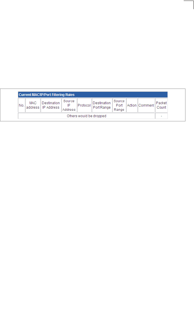
Firewall
5-37
5
•Destination IP Address – Specifies the destination IP address to block or allow traffic
from.
•Source IP Address – Specifies the source IP address to block or allow traffic from.
•Protocol – Specifies the destination port type, TCP, UDP or ICMP. (Default: None).
•Destination Port Range – Specifies the range of destination port to block traffic from
the specified LAN IP address from reaching.
•Source Port Range – Specifies the range of source port to block traffic from the
specified LAN IP address from reaching.
•Action – Specifies if traffic should be accepted or dropped. (Default: Accept)
Comment – Enter a useful comment to help identify the filtering rules.
Figure 5-25. MAC/IP/Port Filtering Rules
Current Filter Rules
The Current Filter Table displays the configured IP addresses and ports that are permitted
or denied access to and from the ADSL/Router.
•Select – Selects a table entry.
•MAC Address – Displays a MAC address to filter.
•Destination IP Address – Displays the destination IP address.
•Source IP Address – Displays the source IP address.
•Protocol – Displays the destination port type.
•Destination Port Range – Displays the destination port range.
•Source Port Range – Displays the source port range.
•Action – Displays if the specified traffic is accepted or dropped.
•Comment – Displays a useful comment to identify the routing rules.
Virtual Server Settings (Port Forwarding)
Virtual Server (sometimes referred to as Port Forwarding) is the act of forwarding a
network port from one network node to another. This technique can allow an external user
to reach a port on a private IP address (inside a LAN) from the outside through a
NAT-enabled router. (Maximum 32 entries are allowed.)
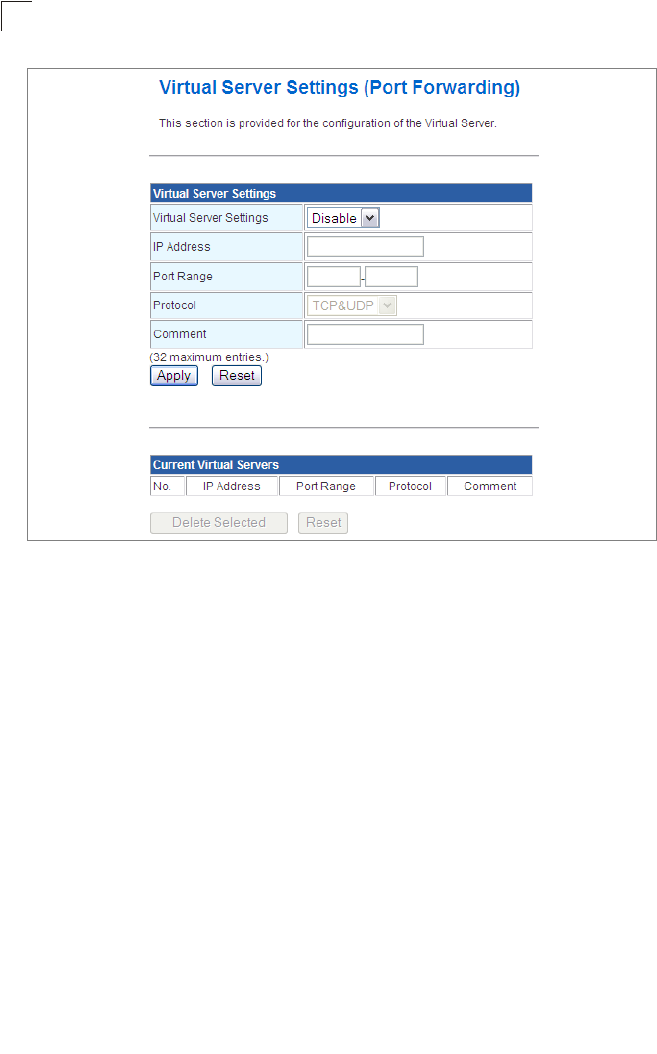
System Configuration
5-38
5
Figure 5-26. Virtual Server Settings (Port Forwarding)
•Virtual Server Setting – Selects between enabling or disabling port forwarding the
virtual server. (Default: Disable)
•IP Address – Specifies the IP address on the local network to allow external access to.
•Port Range – Specifies the port range through which traffic is forwarded.
•Protocol – Specifies a protocol to use for port forwarding, either TCP, UDP or both.
•Comment – Enter a useful comment to help identify the forwarded port service on the
network.
Current Virtual Servers
The Current Virtual Servers displays the entries that are allowed to forward packets
through the Multimedia Router’s firewall.
•Select – Selects an entry in the Current Virtual Servers.
•IP Address – Displays an IP address on the local network to allow external access to.
•Port Range – Displays the local port range.
•Protocol – Displays the protocol used for forwarding of this port.
•Comment – Displays a useful comment to identify the nature of the port to be forwarded.
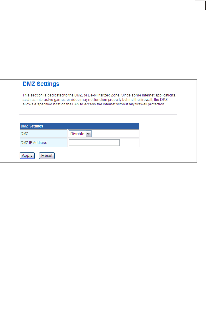
Firewall
5-39
5
DMZ
Enables a specified host PC on the local network to access the Internet without any
firewall protection. Some Internet applications, such as interactive games or video
conferencing, may not function properly behind the Multimedia Router's firewall. By
specifying a Demilitarized Zone (DMZ) host, the PC's TCP ports are completely exposed
to the Internet, allowing open two-way communication. The host PC should be assigned a
static IP address (which is mapped to its MAC address) and this must be configured as
the DMZ IP address.
Figure 5-27. DMZ Settings
•DMZ Settings – Sets the DMZ status to enabled, but changes do not take affect until
the Apply changes button has been pressed and changes are saved to the running
configuration. (Default: Disable)
•DMZ IP Address – Specifies an IP address on the local network allowed unblocked
access to the WAN.
System Security
The Multimedia Router includes the facility to manage it from a remote location. The unit
can also be sent a ping message from a remote location.
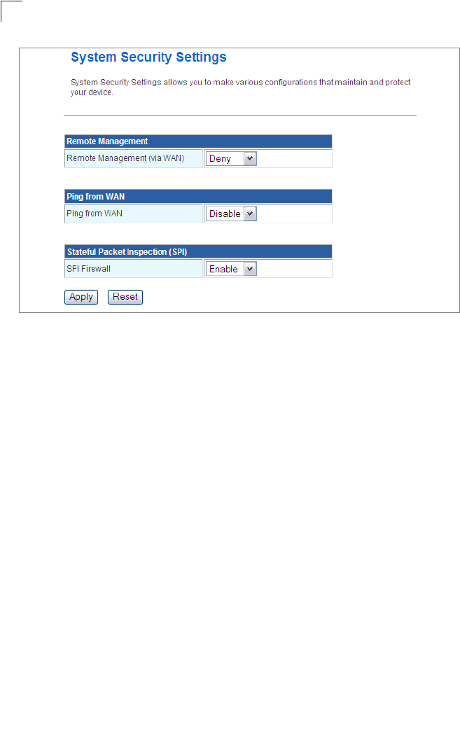
System Configuration
5-40
5
Figure 5-28. System Security Settings
•Remote Management – Denies or allows a remote access via WAN. (Default: Deny)
•Ping from WAN Filter – Sends a ping request on the WAN port to test for connectivity.
(Default: Disable)
•Stateful Packet Inspection (SPI) – The Stateful Packet Inspection (SPI) firewall
protects your network and computers against attacks and intrusions. A stateful packet
firewall looks at packet contents to check if the traffic may involve some type of security
risk. (Default: Enable)
Content Filtering
The Multimedia Router provides a variety of options for blocking Internet access based on
content, URL and host name.
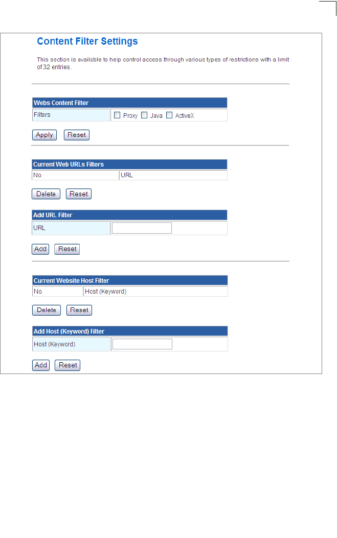
Firewall
5-41
5
Figure 5-29. Filter Settings
Webs Content Filter Settings — The Multimedia Router blocks access to specific
traffic such as proxies, Java Applets and ActiveX. Check the box for whichever service to
be blocked then click “Apply”.
•Filter – Selects Webs content filters. (Options: Proxy/Java/ActivX)
Current Web URLs Filters — By filtering inbound Uniform Resource Locators (URLs)
the risk of compromising the network can be reduced. URLs are commonly used to point
to websites. By specifying a URL or a keyword contained in a URL traffic from that site
may be blocked.
•Current URL Filters – Displays current URL filter.
•Add URL Filter – Adds a URL filter to the settings. For example, myhost.example.com.
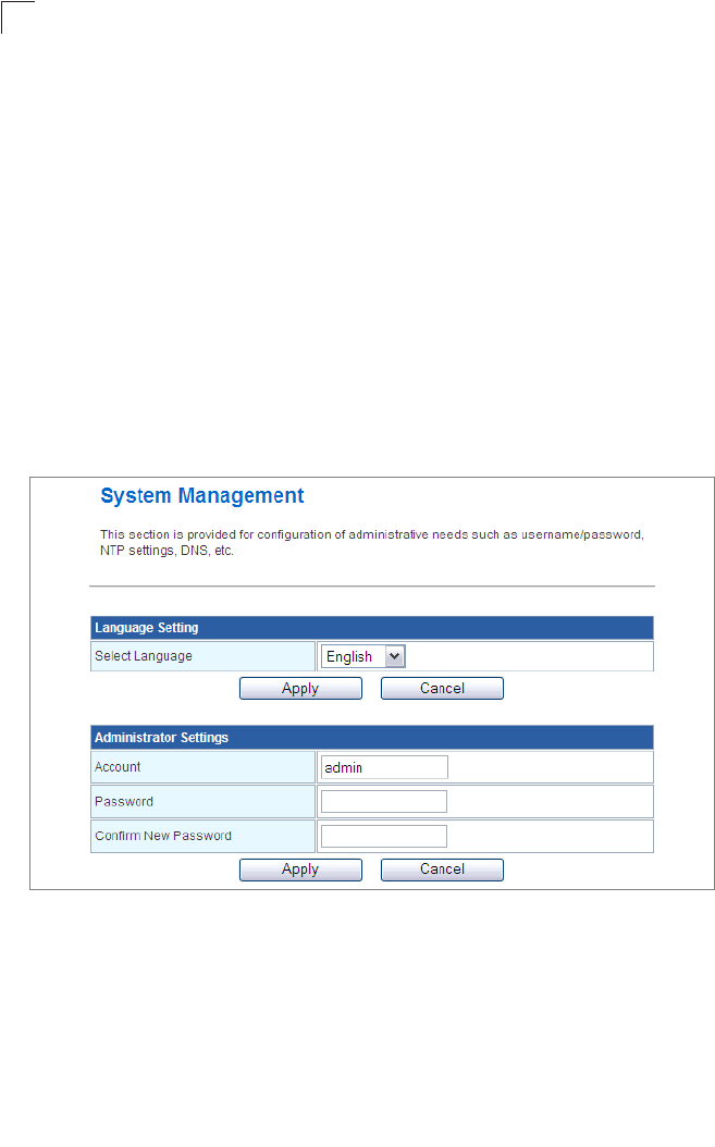
System Configuration
5-42
5
Current Website Host Filters — The Multimedia Router allows Internet content
access to be restricted based on web address keywords and web domains. A domain
name is the name of a particular web site. For example, for the address
www.FUNGAMES.com, the domain name is FUNGAMES.com. Enter the Keyword then
click “Add”.
•Current Host Filters – Displays current Host filter.
•Add Host (Keyword) Filter – Enters the keyword for a host filtering.
Administration Settings
The Multimedia Router’s Administration Settings menu provides the same configuration
options in both Gateway and Bridge Mode. These settings allow you to configure a
management access password, set the system time, upgrade the system software,
display the system status and statistics.
System Management
Figure 5-30. System Management Settings
Language Settings
You can change the language displayed in web interface. Chooses the appropriate
language of your choice from the drop-down list, then click “Apply”. (Options: English/
Traditional Chinese/Simplified Chinese. Default: English)
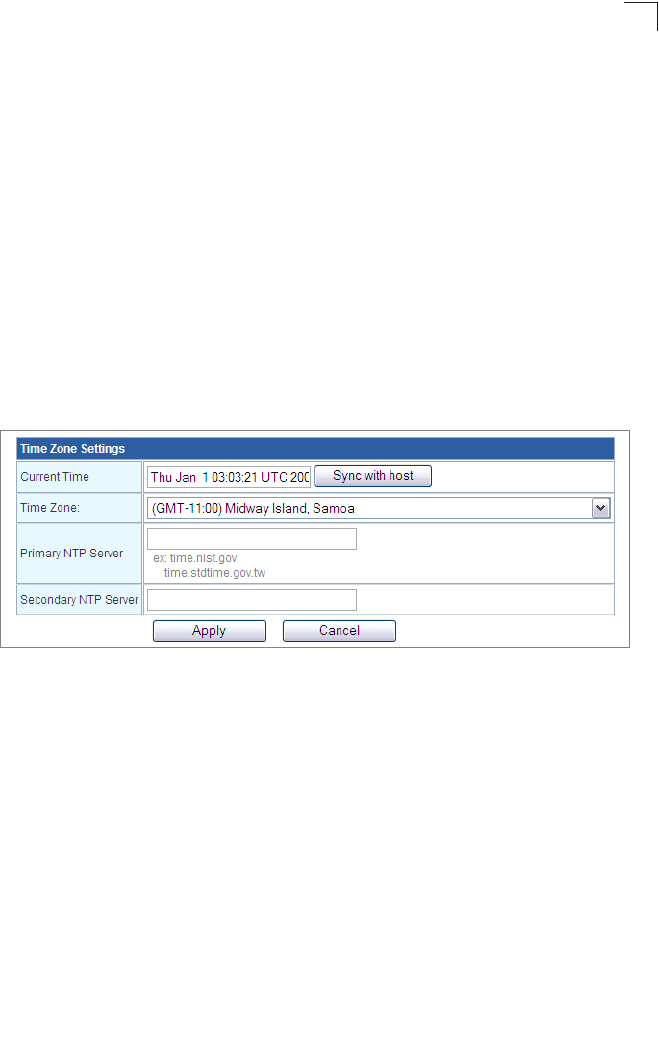
Administration Settings
5-43
5
Administrator Settings
To protect access to the management interface, you need to configure a new
Administrator’s user name and password as soon as possible. If a new user name and
password are not configured, then anyone having access to the Multimedia Router may
be able to compromise the unit's security by entering the default values. Once a new
Administrator has been configured, you can delete the default “admin” user name from
the system.
•Username – The name of the user. The default names preset for access to the unit is
“admin”. (Length: 3-16 characters, case sensitive)
•Password – The password for management access. The default password preset for
access to the unit is “admin” (Length: 3-16 characters, case sensitive)
•Confirm Password – Prompts you to enter the password again for verification.
Time Zone Settings
The System Management page allows you to manually configure time settings or enable
the use of an Network Time Protocol (NTP) server.
Figure 5-31. Time Zone Settings
•Date Time Set By – Allows you to manually configure time settings or select the use of
an NTP server.
•Time Zone – Specifies the time zone in Greenwich Mean Time (GMT).
•Primary/Secondary NTP Server – The IP address or URL of the NTP server to be
used.
Green AP Settings
The GreenAP feature is used for reducing the Multimedia Router's power consumption.
Before setting the Green AP duration, you need to configure the Time Zone Settings first,
then choose one of the options from Action drop-down list. The WiFi Tx Power indicates
how much antenna power you want to use. Less power means the Multimedia Router can
only cover a shorter range. The final step is to set the GreenAP duration. For example,
you might set the TxPower 25% during your sleeping hours, or TxPower OFF while you
are away.
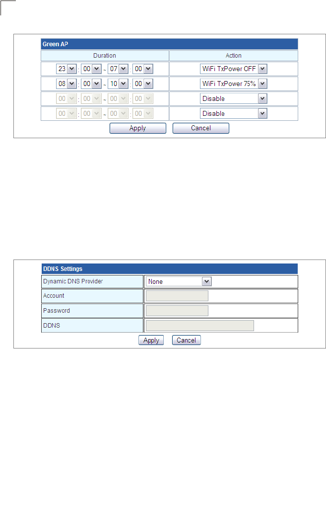
System Configuration
5-44
5
Figure 5-32. Green AP Settings
DDNS Settings
Dynamic DNS (DDNS) provides users on the Internet with a method to tie a specific
domain name to the unit’s dynamically assigned IP address. DDNS allows your domain
name to follow your IP address automatically by changing your DNS records when your
IP address changes.
The Multimedia Router provides access to three DDNS service providers, DynDns.org,
Non-IP.com and ZoneEdit.com. To set up an DDNS account, visit the websites of these
service providers at www.dyndns.org, www.non-ip.com, or www.zoneedit.com.
Figure 5-33. DDNS Setting (Gateway Mode)
•Dynamic DNS Provider – Specifies the DDNS service provider, DynDns.org,
Freedns.afraid.org, ZoneEdit.com or Non-IP.com. (Default: DynDns.org)
•DDNS Account – Specifies your username for the DDNS service.
•DDNS Password – Specifies your password for the DDNS service.
•Apply – Saves and sends the enabled DDNS configuration to the DDNS server.
•Cancel – Cancels the previous DDNS configuration information.
Upgrade Firmware
You can update the Multimedia Router firmware by using the Firmware Update facility.
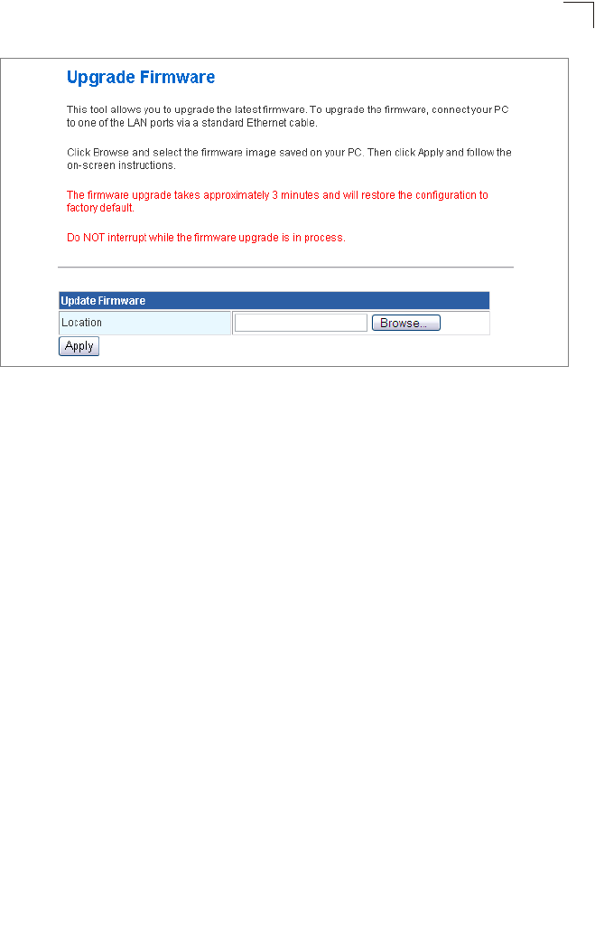
Administration Settings
5-45
5
Figure 5-34. Upgrade Firmware
Update Firmware — Allows you to upload new firmware manually by specifying a file
path. Make sure the firmware you want to use is on the local computer by clicking Browse
to search for the firmware to be used for the update.
•Browse – Opens a directory on the local hard drive for specifying the path of the file to
upload.
•Apply – Starts the upload procedure.
Configuration Settings
The Configuration Setting page allows you to save the Multimedia Router’s current
configuration or restore a previously saved configuration back to the device.
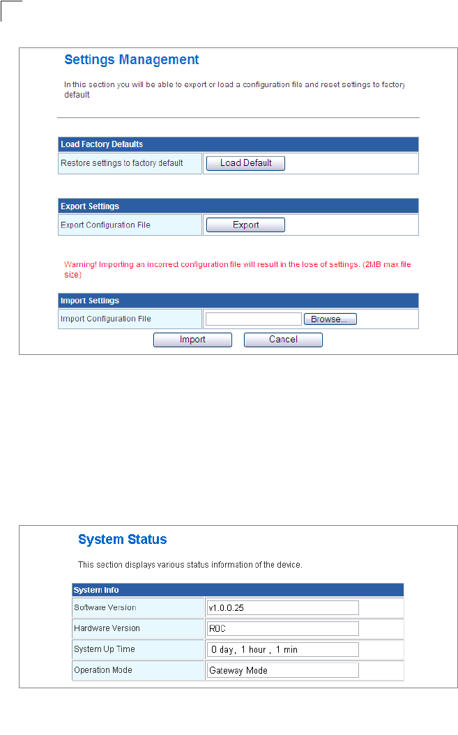
System Configuration
5-46
5
Figure 5-35. Configuration Settings
•Load Factory Defaults – Restores the factory defaults.
•Export – Saves the current configuration to a file locally.
•Import – Allows the user to load previously saved configuration files from a local source.
System Status
The System Information page displays basic system information and the displayed
settings are for status information only and are not configurable on this page. This
information is split into the three sections that follow.
Figure 5-36. System Information - Basic Information
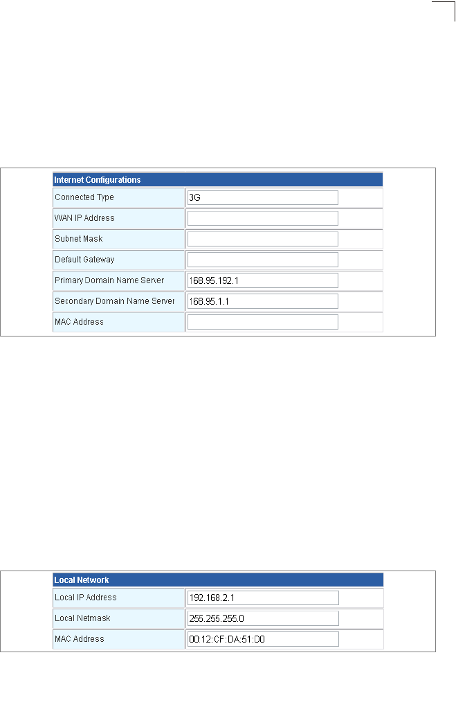
Administration Settings
5-47
5
System Info — Displays the basic system information in both Bridge and Gateway
Modes:
•Software Version – The version number of the current Multimedia Router software.
•Hardware Version – The version number of the current Multimedia Router hardware.
• System Up Time – Length of time the management agent has been up, specified in
hours and minutes.
•Operation Mode – Displays the hardware setting determined by the switch on the base
of the unit.
Figure 5-37. System Information - Internet Configuration (Gateway Mode)
Internet Configurations — Displays the basic WAN information:
•Connected Type – Displays the WAN connected mode. (Default: DHCP)
•WAN IP Address – IP address of the WAN port for this device.
•Subnet Mask – The mask that identifies the host address bits used for routing to the
WAN port.
•Default Gateway – The default gateway is the IP address of the router for the
Multimedia Router, which is used if the requested destination address is not on the local
subnet.
•Primary DNS Server / Secondary DNS Server – The IP address of Domain Name
Servers on the network. A DNS maps numerical IP addresses to domain names and can
be used to identify network hosts by familiar names instead of the IP addresses.
•MAC Address – The shared physical layer address for the Multimedia Router’s LAN
port.
Figure 5-38. System Information - Local Network (Gateway Mode)
Local Network — Displays the basic LAN information:
•Local IP Address – The IP address configured on the Multimedia Router.
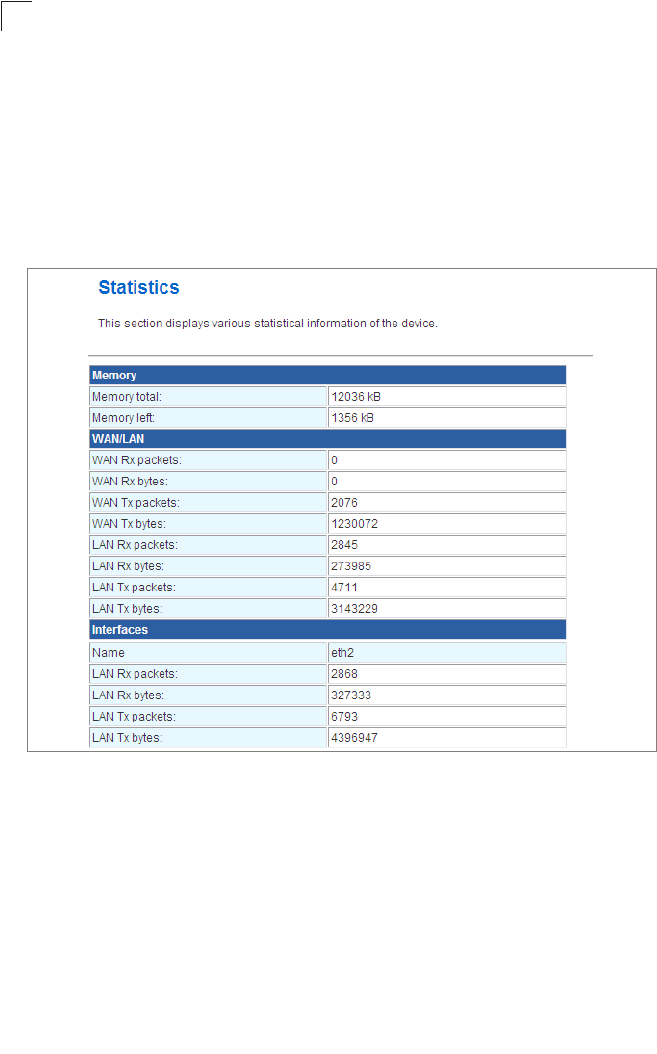
System Configuration
5-48
5
•Local Netmask – The mask that identifies the host address bits used for routing to the
LAN port.
•MAC Address – The shared physical layer address for the Multimedia Router’s LAN
port.
Statistics
The Multimedia Router Traffic Statistics - Interfaces window displays received and
transmitted packet statistics for all interfaces on the Multimedia Router.
Figure 5-39. Statistic
The following items are displayed on this page:
•Memory total – The total memory of this Multimedia Router.
•Memory left – The available memory of this Multimedia Router.
•Interface – Displays the interface on which traffic is being monitored.
•Rx packets – Displays the total number of packets received by the specified interface.
•Rx bytes – Displays the total number of bytes transmitted by the specified interface.
•Tx packets – Displays the total number of packets transmitted by the specified
interfaces.
•Tx bytes – Displays the total number of bytes transmitted by the specified interface.
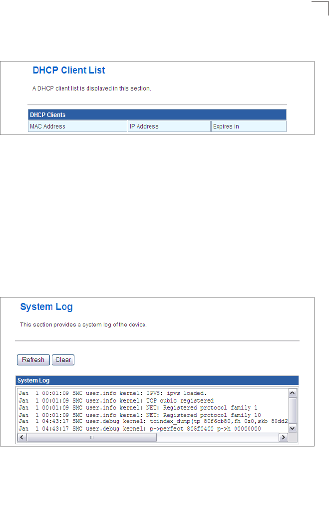
Administration Settings
5-49
5
DHCP Clients
Lists information about associated DHCP clients.
Figure 5-40. DHCP Client List (Gateway Mode)
•MAC Address – The MAC address of the DHCP client.
•IP Address – The IP address of the DHCP client.
•Expires in – The time after which the connection will expire and the DHCP client must
request a new IP address.
System Log
The Multimedia Router supports a logging process that controls error messages saved to
memory or sent to a Syslog server. The logged messages serve as a valuable tool for
isolating Multimedia Router and network problems. The System Log page displays the
latest messages logged in chronological order, from the newest to the oldest. Log
messages saved in the Multimedia Router’s memory are erased when the device is
rebooted.
Figure 5-41. System Logs
•Refresh – Sends a request to add the latest entries to the System Log Table.
•Clear – Removes the current system log messages from the System Log Table.

System Configuration
5-50
5
Reboot
•Reboot – Click the button to reboot the Multimedia Router.
Figure 5-42. System Reboot
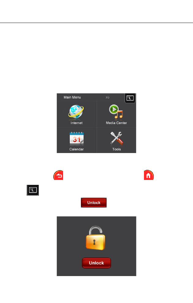
6-1
Chapter 6: Using the On-Screen Display
menus
The Multimedia Router is equipped with a set of user-friendly On-Screen Display
(OSD) menus which provide various functions when your are connected to the
Internet or disconnected.
Using the menus
When the Multimedia Router is powered on, you will hear a ring tone and the main
menu appears on the screen. There are 4 menus on the main menu: Internet, Media
Center, Calendar, and Tools.
To enter each menu and use every sub-menu inside, tap the screen. To go back to
the previous page, tap ; to go back to the main menu, tap .
Note: Tap to turn the screen off when no OSD operation is needed. If you wish to
turn the screen on again, tap .
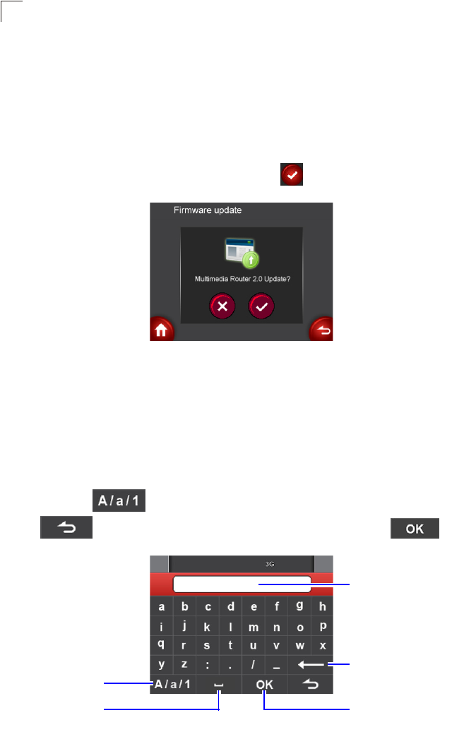
Using the On-Screen Display menus
6-2
6
Updating the Firmware
Upon connecting the Multimedia Router to the Internet, the unit will check
automatically if any updated firmware is ready for installation. Follow the steps below
to complete firmware update.
Note: Before updating firmware, make sure at least 128MB of free space is available in
the Multimedia Router’s internal memory.
1. When prompted to update the firmware, tap .
2. The Router Frame starts downloading and installing the latest firmware. During
installation, do not unplug the power adapter nor disconnect from Internet.
3. When finished, restart your Multimedia Router.
Using the Keypad
When the keypad screen is displayed, you can tap the corresponding letter on the
screen to enter the text. To switch among upper case/lower case/number input
methods, tap . To leave the keypad screen without saving any changes,
tap . To save input texts and go back to the last screen, tap .
Text input box
Shift among
upper/lower
case letters
and numbers.
Delete the letter
left of the cursor.
Enter a space.
Save input texts
and go back to
the last screen.
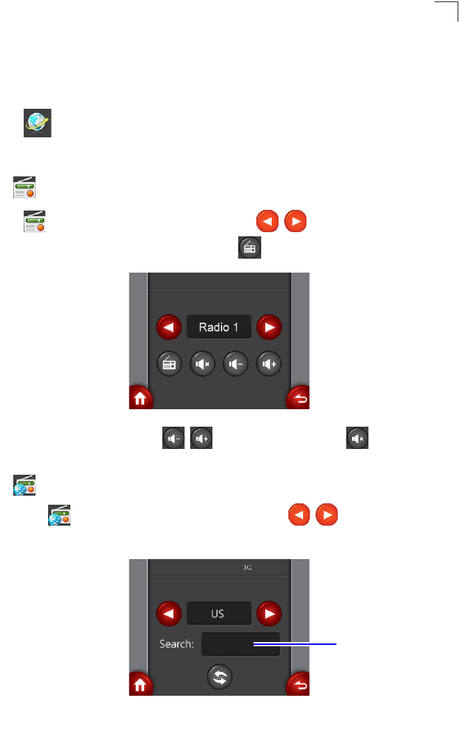
The Internet menu
6-3
6
The Internet menu
Note: Before using this menu, make sure the Multimedia Router is connected to the
Internet.
Tap to open the Internet menu, and you can select to access Internet radio,
video clips or photo albums.
• Internet Radio
Tap to enter the Internet Radio screen. Tap / to select a preset
Internet radio station to listen to and then tap to start playback.
- To adjust the volume, tap / . To mute the sound, tap .
• YouTube
1. Tap to enter the YouTube setting screen. Tap / to select the video
location.
Search: box
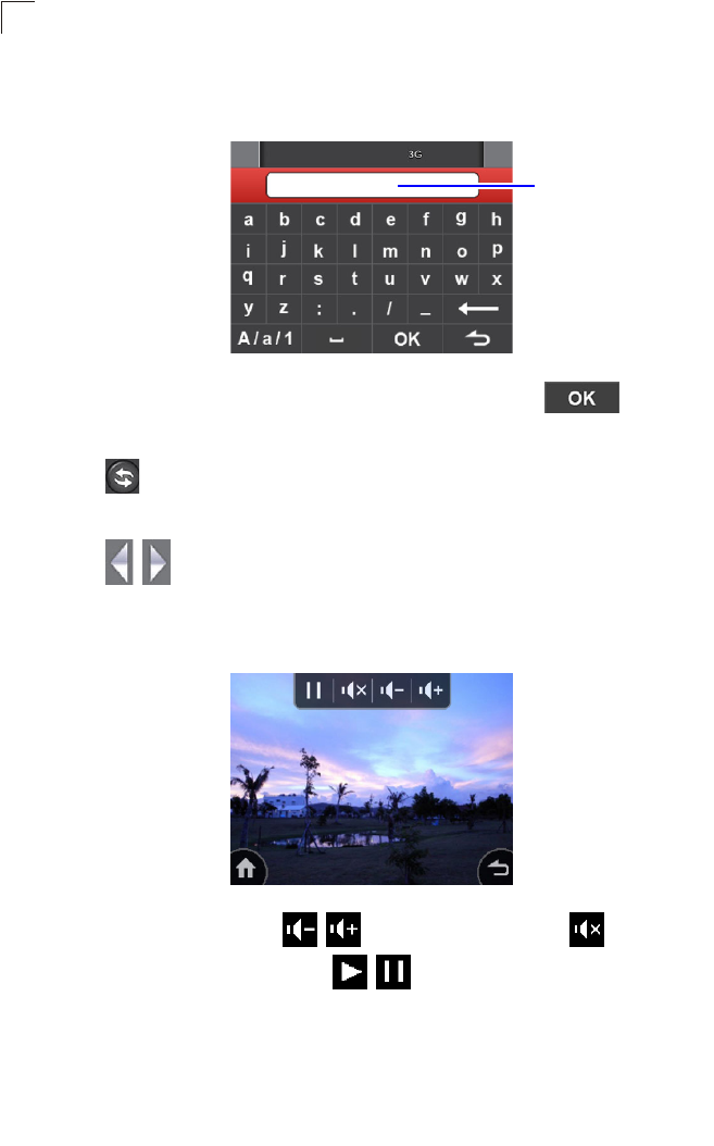
Using the On-Screen Display menus
6-4
6
2. To input the keyword for your desired video clips, tap anywhere inside the
Search: box to enter the Keypad screen.
3. Enter the keyword in the text input box. When finished, tap to go back
to the YouTube setting screen.
4. Tap to start searching. After a few seconds, the preview of the most
viewed video clip concerning the keyword with its title appears on the screen.
5. Tap / to go to the previous/next video clip, or tap anywhere inside the
preview frame to start playback of the video clip in full screen.
6. Tap anywhere on the screen to display the tool bar.
- To adjust the volume, tap / . To mute the sound, tap .
- To pause/resume playback, tap / .
Note: If you start searching without entering any keyword, the screen will display today’s
most viewed video clip in your selected location.
Text input box
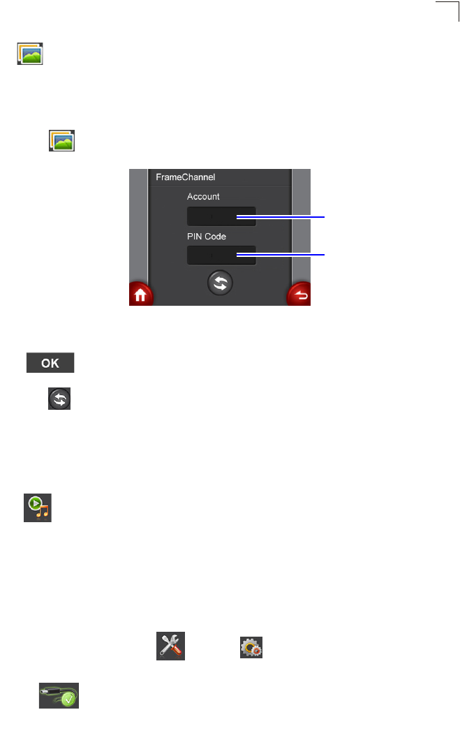
The Media Center menu
6-5
6
• FrameChannel
Note: To use FrameChannel, you will need to register a FrameChannel account on the
Internet first and then upload photos to your FrameChannel Web Album. Go to
www.framechannel.com. for details on how to manage your account.
1. Tap to enter the FrameChannel setting screen.
2. Tap the Account name/PIN Code input box to enter the keypad screen. Enter
your account name/PIN Code in the text input box. When finished, tap
.to go back to the FrameChannel setting screen.
3. Tap to log on to your FrameChannel web album. After a few seconds, your
photos will be displayed in a slideshow.
The Media Center menu
Tap to open the Media Center menu, and you can select to listen to FM radio
or to play back photo/music/video files on your Multimedia Router. Before playing
back any files, you will need to copy files to the Multimedia Router’s internal memory
first.
To copy files to the Multimedia Router:
1. Take a USB cable and connect the larger end to the USB port of the
computer, and the smaller end to the USB socket on the Multimedia Router.
2. In the main menu, tap and then Connect to PC.
3. The Multimedia Router is ready for use as mass storage device when
appears on the screen. You can start copying photo/music/video
files from the computer into the unit.
Account name
input box
PIN Code input
box

Using the On-Screen Display menus
6-6
6
4. When finished, tap to disconnect the Multimedia Router from your
computer.
• FM Radio
Tap to enter the FM radio screen. The preset FM radio station starts
broadcasting automatically. You can save up to 5 most-listened-to radio stations by
adding them to your favorite station list.
- To manually search for radio stations in sequential order, tap / to adjust
the frequency.
- To rapidly scan for stations with signals, tap / .
- To manage your favorite station list, tap to select one channel number (for
example, ) first. Adjust current frequency to the station you want, and then
tap to save it to the selected channel number.
- To adjust the volume, tap / . To mute the sound, tap .
• Photo
To display the photos, you need to copy photo files to the Multimedia Router first.
For details, see “To copy files to the Multimedia Router:” on page 6-5.
Tap and then Internal Memory. The stored photo files will be displayed in
thumbnails of four per page. To view the previous/next page, tap / . To view
the pic in full screen, tap a thumbnail.
Favorite station list
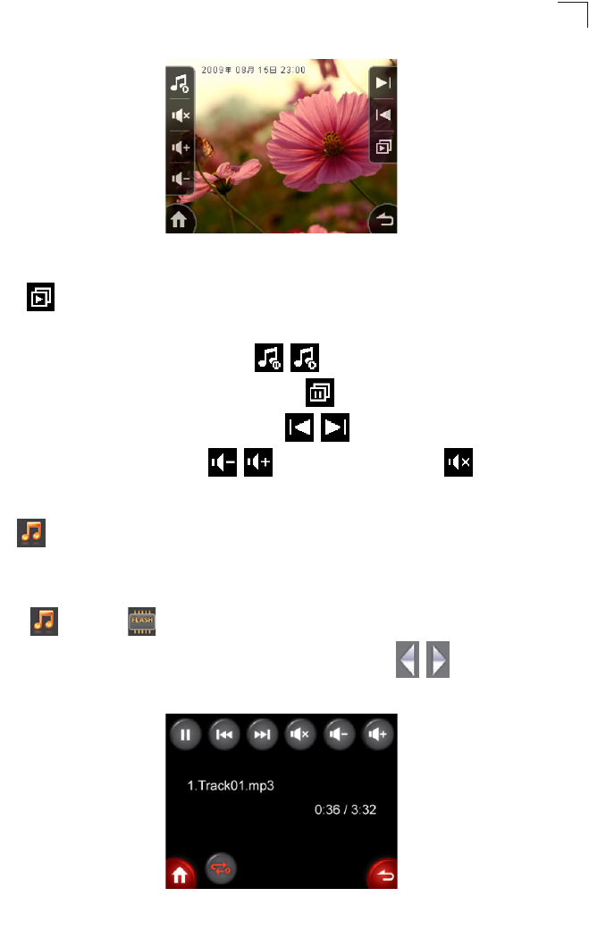
The Media Center menu
6-7
6
Tap anywhere on the screen to display the tool bar. To view the photos in slideshow,
tap . Playback of music also starts if one or more music files are stored in the
internal memory.
- To pause/resume the music, tap / .
- To switch back to single photo view, tap .
- To go to the previous/next photo, tap / .
- To adjust the volume, tap / . To mute the sound, tap .
• Music
To play back music, you need to copy music files to the Multimedia Router first. For
details, see “To copy files to the Multimedia Router:” on page 6-5.
Tap and then Internal Memory. The stored music files will be displayed in
a list of four per page. To view the previous/next page, tap / . To listen to the
music, tap a track.
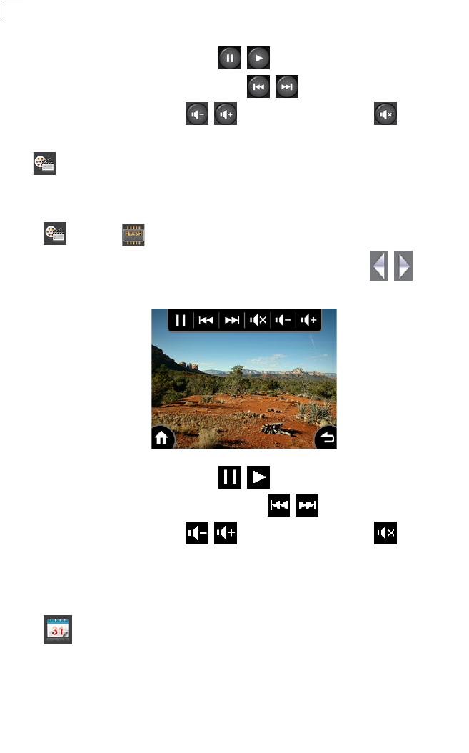
Using the On-Screen Display menus
6-8
6
- To pause/resume playback, tap / .
- To go to the previous/next photo, tap / .
- To adjust the volume, tap / . To mute the sound, tap .
• Video
To view video clips, you need to copy video files to the Router first. For details, see
“To copy files to the Multimedia Router:” on page 6-5.
Tap and then Internal Memory. The stored video files will be displayed in
thumbnails of four per page. To view the previous/next page, tap / . To view
the video, tap a thumbnail.
- To pause/resume playback, tap / .
- To go to the previous/next video clip, tap / .
- To adjust the volume, tap / . To mute the sound, tap .
The Calendar menu
Tap to open the Calendar menu, and you can view and set up calendar and
clock/alarm time.
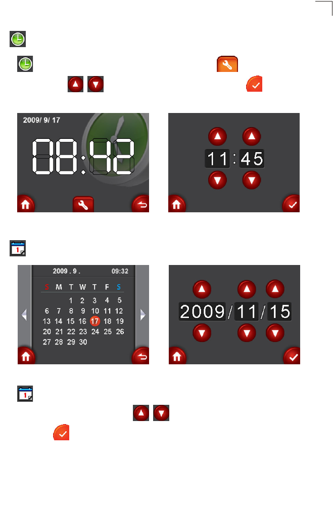
The Calendar menu
6-9
6
• Clock
Tap to view the current time. To adjust the time, tap to open the time
setting page. Tap / to adjust it to your local time, and tap to confirm the
settings.
• Calendar
Tap to view the current date. To adjust the date, tap anywhere on the calendar
to open the date setting page. Tap / to adjust it to the correct year/month/
date, and tap to confirm the settings.
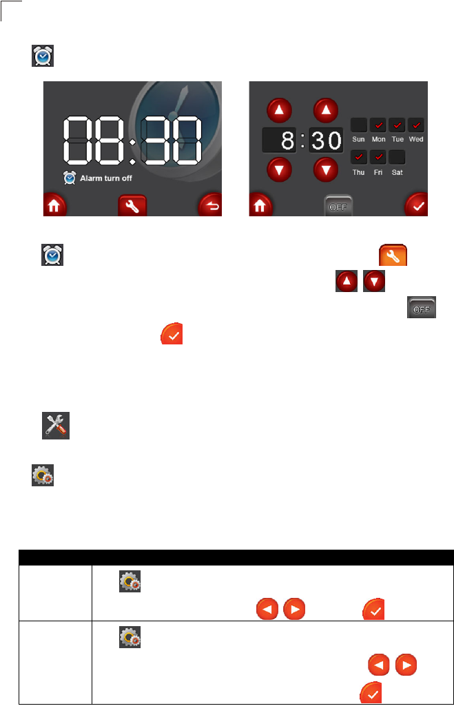
Using the On-Screen Display menus
6-10
6
• Alarm
Tap to view the current alarm settings. To adjust the settings, tap to open
the alarm setting page. You can set the alarm time by tapping / , and tap the
day(s) you need the alarm through Sunday to Saturday. When finished, tap to
activate the alarm, and tap to confirm the settings.
The Tools menu
Tap to open the Tools menu, and you can adjust settings about the
Multimedia Router and the network.
• Setup
The Setup menu contains the functions to be set according to your personal needs.
It also provides the option for you to reset all settings to factory preset values.
Table 6-1. Setup
Menu name •Description
Language Ta p Language to open the Language setting page. To change
the current OSD language, tap / , and then to confirm.
Brightness/
Contrast
Tap Brightness/Contrast to open the Brightness/Contrast
setting page. To adjust current backlight settings, tap / on
either side of the item you want to change, and tap to confirm.

The Tools menu
6-11
6
• Connect to PC
Ta p Connect to PC to use the Multimedia Router as the mass storage device.
For more details, see “To copy files to the Multimedia Router:” on page 6-5.
• Network Setting
You can set up basic 3G/WAN/WiFi settings as well as monitor the Internet connection
status of the Multimedia Router.
Network Setting
Tap Network Setting and then Network Setting.
Default
Setting
To return all the settings to the factory preset values, tap Default
Setting and then Execute to reset all settings.
Format To erase all data stored in the internal memory, tap Format and
then
Format to format the internal space of the Multimedia
Router.
LCD
Schedule
Tap LCD Schedule to open the LCD backlight schedule setting
page. You can save power by scheduling to reduce the screen
backlight level. Tap / to adjust the initial time of power-saving
mode, duration, percentage of the backlight level and whether to turn
on the schedule. When finished, tap to confirm selection.
Table 6-1. Setup
Menu name •Description
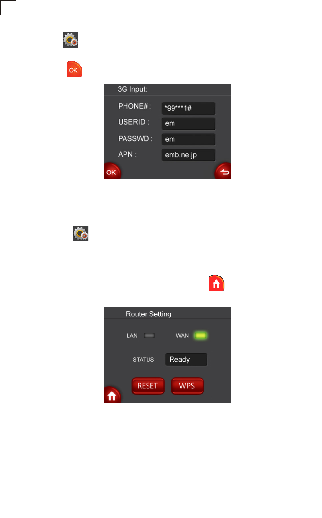
Using the On-Screen Display menus
6-12
6
-3G: Tap 3G setting if you use 3G as the Internet connection method. The 3G
connection setting info appears. Fill in the info using the on-screen keypad. When
done, tap .
Note:To use this option, you need to first connect a 3G/3.5G USB modem to the
USB port on the back of the unit and have registered an account with a
cellular operator. For more details on the 3G settings, see “3G” on page 5-14 .
-WAN: Tap WAN setting if you use WAN as the Internet connection
method.
1. By default, your multimedia router automatically detects and obtains an IP
address from a DHCP server. When connected to the Internet successfully, below
Network status page appears on the screen. Tap to leave and go back to the
main menu.
2. If the connection fails, the WAN connection type automatically sets to PPPoE.
Enter the PPPoE username and password for the WAN port using the on-screen
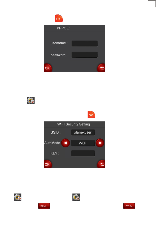
The Tools menu
6-13
6
keypad. When done, tap .
Note: To use this option, you need to first connect your multimedia router to an
Internet connected cable or ADSL modem, and wired or wireless PCs or
notebooks. See “Installation” on page 2-1 for detailed installation. For more
details on the WAN settings, see “WAN Setting” on page 5-4.
-WiFi: Tap WiFi Setting if you use WiFi as the Internet connection method.
Select the security mode and enter its SSID and password accordingly, if needed,
using the on-screen keypad. When done, tap .
Note:For more details on WiFi settings, see “Configuring Wi-Fi Multimedia” on page
5-28.
-
Router setting
Tap Network Setting and then Router Setting to enter the Network
status page. Tap to reboot the router when needed. Tap to
activate the WPS function. For detailed WPS instructions, see “Wi-Fi Protected
Setup (WPS)” on page 5-33.

Using the On-Screen Display menus
6-14
6
When the green light is on, it indicates that the LAN/WAN connection is successful.
Note: If you wish to use this function, your LAN IP address must be set to “192.168.1.1”
(default).
• System Information
To view the system information, tap System Information. The System
Information page appears. You can check the firmware version, and available
internal memory space of the Multimedia Router.

A-1
Appendix A: Troubleshooting
Check the following items before you contact local Technical Support.
1. If wireless clients cannot access the network, check the following:
• Be sure the access point and the wireless clients are configured with the same
Service Set ID (SSID).
• If authentication or encryption are enabled, ensure that the wireless clients are
properly configured with the appropriate authentication or encryption keys.
2. If the Multimedia Router cannot be configured using a web browser:
• Be sure to have configured the access point with a valid IP address, subnet
mask and default gateway.
• If you are connecting to the Multimedia Router through the wired Ethernet
interface, check the network cabling between the management station and the
Multimedia Router. If you are connecting to Multimedia Router from a wireless
client, ensure that you have a valid connection to the Multimedia Router.
3. If you forgot or lost the password:
• Set the Multimedia Router to its default configuration by pressing the reset
button on the bottom panel. Connect to the web management interface using
the default IP address 192.168.2.1. Then set up a new user name and
password to access the management interface.
4. If all other recovery measure fail, and the Multimedia Router is still not
functioning properly, take any of these steps:
• Reset the Multimedia Router’s hardware using the web interface or through a
power reset.
• Reset the Multimedia Router to its default configuration by pressing the reset
button on the back panel. Connect to the web management interface using the
default IP address 192.168.2.1, then setup a user name and password.

Troubleshooting
A-2
A

B-1
Appendix B: Specifications
Operating Frequency
802.11b/g/n:
2.412 ~ 2.462 GHz (USA, Canada Ch1- Ch11)
2.412 ~ 2.472 GHz (Europe Ch1- Ch13)
2.412 ~ 2.484 GHz (Japan Ch1- Ch13)
2.412 ~ 2.462 GHz (Taiwan Ch1-Ch11)
Data Rate
802.11b: 1, 2, 5.5, 11 Mbps per channel
802.11g: 6, 9, 12, 18, 24, 36, 48, 54 Mbps per channel
802.11n: MCS 0~7
Operating Channels
802.11b/g/n compliant:
11 channels (US, Canada)
13 channels (ETSI, Japan)
11 channels (Taiwan)
Modulation Type
CCK, DQPSK, DBPSK for DSSS
64QAM, 16QAM, QPSK, BPSK for OFDM
Frequency Range
FCC/NCC: 2412MHz ~ 2462MHz
CE: 2412MHz ~ 2472MHz
AC Power Adapter
Input: 110 or 240 VAC, 50-60 Hz
Output: 5V, 2A
Network Management
Web-browser
Temperature
Operating: 0 to 45 °C (32 to 113 °F)
Storage: 0 to 45 °C (32 to 113 °F)
Humidity
5% to 95% (non-condensing)
Compliances
FCC Part 15B Class B
EN 55022
EN 55024
EN61000-3-2
EN61000-3-3

Specifications
B-2
B
Radio Signal Certification
FCC Part 15C 15.247, 15.207 (2.4 GHz)
EN 300 328
EN 301 489-1
EN 301 489-17
Standards
IEEE 802.11b/g
IEEE 802.11n draft v2.0
Physical Size
193 x 119 x 130 mm (7.60 x 4.69 x 5.12 in)
Weight
< 450 g (15.87 oz)

Glossary-1
Glossary
10BASE-T
IEEE 802.3-2005 specification for 10 Mbps Ethernet over two pairs of Category 3 or better
UTP cable.
100BASE-TX
IEEE 802.3-2005 specification for 100 Mbps Fast Ethernet over two pairs of Category 5 or
better UTP cable.
Access Point
An internetworking device that seamlessly connects wired and wireless networks. Access
points attached to a wired network, support the creation of multiple radio cells that enable
roaming throughout a facility.
Advanced Encryption Standard (AES)
An encryption algorithm that implements symmetric key cryptography. AES provides very
strong encryption using a completely different ciphering algorithm to TKIP and WEP.
Authentication
The process to verify the identity of a client requesting network access. IEEE 802.11
specifies two forms of authentication: open system and shared key.
Backbone
The core infrastructure of a network. The portion of the network that transports
information from one central location to another central location where it is unloaded onto
a local system.
Beacon
A signal periodically transmitted from the access point that is used to identify the service
set, and to maintain contact with wireless clients.
Broadcast Key
Broadcast keys are sent to stations using dynamic keying. Dynamic broadcast key
rotation is often used to allow the access point to generate a random group key and
periodically update all key-management capable wireless clients.
Dynamic Host Configuration Protocol (DHCP)
Provides a framework for passing configuration information to hosts on a TCP/IP network.
DHCP is based on the Bootstrap Protocol (BOOTP), adding the capability of automatic
allocation of reusable network addresses and additional configuration options.

Glossary
Glossary-2
Encryption
Data passing between the access point and clients can use encryption to protect from
interception and evesdropping.
Ethernet
A popular local area data communications network, which accepts transmission from
computers and terminals.
File Transfer Protocol (FTP)
A TCP/IP protocol used for file transfer.
Hypertext Transfer Protocol (HTTP)
HTTP is a standard used to transmit and receive all data over the World Wide Web.
IEEE 802.11b
A wireless standard that supports wireless communications in the 2.4 GHz band using
Direct Sequence Spread Spectrum (DSSS). The standard provides for data rates of 1, 2,
5.5, and 11 Mbps.
IEEE 802.11g
A wireless standard that supports wireless communications in the 2.4 GHz band using
Orthogonal Frequency Division Multiplexing (OFDM). The standard provides for data
rates of 6, 9, 11, 12, 18, 24, 36, 48, 54 Mbps. IEEE 802.11g is also backward compatible
with IEEE 802.11b.
IEEE 802.11n
A wireless standard that supports wireless communications in the 2.4 GHz band using
Orthogonal Frequency Division Multiplexing (OFDM). The standard provides for data
rates of 27, 54, 81, 108, 162, 216, 243, 270, 300 Mbps. IEEE 802.11n is also backward
compatible with IEEE 802.11b/g.
Infrastructure
An integrated wireless and wired LAN is called an infrastructure configuration.
Local Area Network (LAN)
A group of interconnected computer and support devices.
MAC Address
The physical layer address used to uniquely identify network nodes.
Network Time Protocol (NTP)
NTP provides the mechanisms to synchronize time across the network. The time servers
operate in a hierarchical-master-slave configuration in order to synchronize local clocks
within the subnet and to national time standards via wire or radio.

Glossary-3
Glossary
Open System
A security option which broadcasts a beacon signal including the access point’s
configured SSID. Wireless clients can read the SSID from the beacon, and automatically
reset their SSID to allow immediate connection to the nearest access point.
Orthogonal Frequency Division Multiplexing (ODFM)
OFDM allows multiple users to transmit in an allocated band by dividing the bandwidth
into many narrow bandwidth carriers.
Repeater and Bridge
Repeater and bridge can provide an extended link to a remote access point from the
wired LAN. Access Point working in this mode could connect to another AP in Access
Point mode or Repeater and Bridge mode. Whenever there are two APs having wireless
link together (one in Access Point or Repeater and Bridge mode, another using Repeater
and Bridge mode), and also have wired link separately, these two APs are also working
as “bridging” for the two wired links.
Service Set Identifier (SSID)
An identifier that is attached to packets sent over the wireless LAN and functions as a
password for joining a particular radio cell; i.e., Basic Service Set (BSS).
Session Key
Session keys are unique to each client, and are used to authenticate a client connection,
and correlate traffic passing between a specific client and the access point.
Shared Key
A shared key can be used to authenticate each client attached to a wireless network.
Shared Key authentication must be used along with the 802.11 Wireless Equivalent
Privacy algorithm.
Simple Network Time Protocol (SNTP)
SNTP allows a device to set its internal clock based on periodic updates from a Network
Time Protocol (NTP) server. Updates can be requested from a specific NTP server, or can
be received via broadcasts sent by NTP servers.
Temporal Key Integrity Protocol (TKIP)
A data encryption method designed as a replacement for WEP. TKIP avoids the problems
of WEP static keys by dynamically changing data encryption keys.
Trivial File Transfer Protocol (TFTP)
A TCP/IP protocol commonly used for software downloads.
Virtual Access Point (VAP)
Virtual AP technology multiplies the number of Access Points present within the RF
footprint of a single physical access device. With Virtual AP technology, WLAN users

Glossary
Glossary-4
within the device’s footprint can associate with what appears to be different access points
and their associated network services. All the services are delivered using a single radio
channel, enabling Virtual AP technology to optimize the use of limited WLAN radio
spectrum.
Wi-Fi Protected Access
WPA employs 802.1X as its basic framework for user authentication and dynamic key
management to provide an enhanced security solution for 802.11 wireless networks.
Wired Equivalent Privacy (WEP)
WEP is based on the use of security keys and the popular RC4 encryption algorithm.
Wireless devices without a valid WEP key will be excluded from network traffic.
WPA Pre-shared Key (WPA-PSK)
WPA-PSK can be used for small office networks with a limited number of users that may
not need a high level of security. WPA-PSK provides a simple security implementation
that uses just a pre-shared password for network access.

Index-1
A
AC power adapter 1-3
administrator password 5-43
administrator username 5-43
Advanced Setting menu 5-25
AP mode 2-2
authentication mode 5-31
B
bridge 3-3, 5-23
C
channels, maximum B-1
clients, maximum B-1
contents, package 1-1
D
DDNS 5-44
DHCP client list 5-49
DHCP server address 5-47
E
Ethernet ports 1-3
F
firmware version 5-47
G
gateway address 4-10, 5-14, 5-19,
5-20, 5-47
H
host name 5-47
I
IEEE 802.11n 1-1
IP address 4-4, 5-7, 5-17, 5-47
L
LAN setting 5-16
M
MDI/MDI-X, automatic 1-3
N
NTP server 5-43
P
package checklist 1-1
power socket 1-3
PPPoE 4-8, 4-9, 5-12, 5-14
R
reboot 5-50
repeater 5-23
S
secondary DNS server 4-5, 5-8
subnet mask 4-4, 5-8, 5-17, 5-47
system Information 5-46
T
time zone 5-43
troubleshooting A-1
W
WAN setting 5-4
WDS settings 5-23
WEP 5-30, 5-32
WLAN setting 5-21
WPS 5-33
WPS, PBC 5-35
WPS, PIN 5-35
Index

Index-2

M
ultimedia Rout
er
M
ZK-WDPR
M
ZK-WDPR