Qisda UH100I Diagnostic Ultrasound System User Manual Part I
Qisda Corporation Diagnostic Ultrasound System Part I
Qisda >
Contents
- 1. User manual_Part I
- 2. User manual_Part II
User manual_Part I
UH100
Diagnostic Ultrasound System
User Manual

2
Copyright
Copyright
Copyright 2015 Qisda Corporation. All rights reserved. No part of this
publication may be reproduced, transmitted, transcribed, stored in a
retrieval system or translated into any language or computer language,
in any form or by any means, electronic, mechanical, magnetic, optical,
chemical, manual or otherwise, without the prior written permission of
Qisda Corporation.
All other logos, products, or company names mentioned in this
manual are the registered trademarks or copyrights of their respective
companies, and are used for informational purposes only.
Disclaimer
Qisda Corporation makes no representations or warranties, either
expressed or implied, with respect to the contents hereof and specifically
disclaims any warranties, merchantability or fitness for any particular
purpose. Further, Qisda Corporation reserves the right to revise this
publication and to make changes from time to time in the contents hereof
without obligation of Qisda Corporation to notify any person of such
revision or changes.
This User Manual aims to provide the most updated and accurate
information to customers, and thus all contents may be modified from
time to time without prior notice.
Limit of liability
All contents and services accessible through this device belong to third
parties and are protected by the laws on copyright, patents, trademarks
and/or other intellectual property laws. These contents and services
are provided solely for your personal use and not for commercial use.
You cannot use them without the explicit permission from the content
owner or service provider. Without limiting the foregoing, except with
the express authorization of the content owner or of the supplier of
the services concerned, you are forbidden to modify, copy, republish,
transfer, distribute, transmit, translate, sell, exploit or create derivatives,
in any manner and on any medium, regardless of the content or services
displayed by the intermediary of this device.
Qisda is not responsible for the content of the websites or of similar
resources, which are maintained and controlled by third parties, that
may be linked from this product. Providing links to those websites or
to similar resources does not mean that Qisda makes any warranty or
representation to their content by expression or by implication.

3
Contact information
Any third party content or service preinstalled in this product is provided
“as is”. Qisda does not, by expression or by implication, make any
warrant to the content or to the services provided by third parties. Qisda
does not warrant or guarantee that the content or services provided by
third parties are accurate, effective, most up-to-date, legal, or complete.
Under no circumstances shall Qisda be liable for the content or services
provided by third parties including their negligence.
Services provided by third parties may be terminated temporarily or
permanently. Qisda does not warrant or guarantee that any content or
services provided by third parties are in good condition at any time, and
is not liable for the termination of the said content and services.
In addition, Qisda is not involved in any transactions you conduct in the
websites or similar resources maintained by third parties.
You should contact the content or service providers for any questions,
concerns, or disputes.
Contact information
Manufacturer
Name: Qisda Corporation
Address: 1st, 5th, 7th Floors, No. 159, Shan-Ying Road, Shan-Ting Li,
Gueishan Dist., Taoyuan City, Taiwan, R.O.C.
EU Authorised Representative
Name: Mednet Gmbh
Address: Borkstrasse 10, 48163 Muenster, Germany
v0.16_en bn61426
15/09/30

4
Table of contents
Table of contents
Copyright ................................................................................................. 2
Disclaimer ............................................................................................... 2
Limit of liability ......................................................................................... 2
Contact information ................................................................................. 3
Chapter 1 Introduction ...............................................................8
About ultrasound ..................................................................................... 8
Medical purpose ...................................................................................... 8
Equipment list .......................................................................................... 9
About the User Manual ........................................................................... 9
Specifications ........................................................................................ 10
System ............................................................................................. 10
Battery .............................................................................................. 11
Transducer ....................................................................................... 12
Power adapter .................................................................................. 13
System warranty ................................................................................... 13
Chapter 2 Safety information ...................................................14
Warning symbols ................................................................................... 16
System label icons ........................................................................... 16
System button .................................................................................. 17
Transducer label icons ..................................................................... 17
Shipping label icons ......................................................................... 17
Electrical safety ..................................................................................... 18
Battery usage/disposal ..................................................................... 20
Electrical Fast Transients (EFT) ....................................................... 20
Electromagnetic Interference (EMI) ................................................. 20
Surges to mains power supply ......................................................... 24
Electromagnetic Interference (EMI) ................................................. 24
RF safety ............................................................................................... 25
Biological safety .................................................................................... 25
Heating ............................................................................................. 26
Cavitation ......................................................................................... 26
Safe scanning guideline ................................................................... 26
Temperature display for transducers intended for internal use ........ 28

5
Table of contents
Waterproof and dustproof ratings .......................................................... 28
Understand the MI/TI display ................................................................ 29
Tissue model .................................................................................... 32
TI ...................................................................................................... 33
MI ..................................................................................................... 33
Display and report in different modes .............................................. 34
Operator control features ................................................................. 34
Transducer surface temperature rise .................................................... 34
Intended use ......................................................................................... 35
Indications for use ................................................................................. 37
Chapter 3 Get Started ............................................................... 41
System overview ................................................................................... 41
Front and side views ........................................................................ 41
Rear and top/bottom views .............................................................. 42
Insert a microSD card (optional) ........................................................... 43
Use the stand ........................................................................................ 44
Charge the system ................................................................................ 45
Connect the transducer ......................................................................... 46
Remove the transducer ......................................................................... 46
Use the system on the go ..................................................................... 47
Wall-mount the system .......................................................................... 48
Output the system display to an HDMI-enabled TV or monitor ............. 48
Chapter 4 Basic operations .....................................................49
Turn on the system ............................................................................... 49
Identify the main screen layout ............................................................. 51
System menu screen ....................................................................... 51
Imaging screen (Real-time) .............................................................. 52
Imaging screen (Frozen) .................................................................. 54
Switch the control panel pages ........................................................ 56
Add a new patient ................................................................................. 57
To update patient information .......................................................... 57
Load a work list ..................................................................................... 58
Select a preset ...................................................................................... 59
To modify current presets ................................................................ 59

6
Table of contents
Set the transducer orientation ............................................................... 60
Adjust the displayed image ................................................................... 60
Enlarge an area of the image ........................................................... 61
Split the imaging screen ................................................................... 62
Freeze an image ................................................................................... 62
Add annotations and measurements .................................................... 63
Annotations ...................................................................................... 63
Arrow ................................................................................................ 63
Label ................................................................................................ 64
BDMK ............................................................................................... 64
Measurements ................................................................................. 65
Save and print the image ...................................................................... 66
Save an image ................................................................................. 66
Save a cine clip ................................................................................ 66
Print an image .................................................................................. 66
Review the image .................................................................................. 67
Perform multiple selections .............................................................. 67
Compare images .............................................................................. 68
Generate a report ............................................................................. 68
Export the exam .................................................................................... 69
End the exam ........................................................................................ 69
Chapter 5 Scan modes overview .............................................70
B mode overview ................................................................................... 70
B mode image controls .................................................................... 71
Color/Power Doppler mode overview .................................................... 72
Color/Power Doppler mode image controls ..................................... 73
M mode overview .................................................................................. 74
M mode image controls .................................................................... 74
Pulsed-Wave (PW) Doppler mode overview ......................................... 75
PW Doppler mode image controls ................................................... 75
Chapter 6 IT Network ................................................................ 77
Introduction ........................................................................................... 77
Specifications ........................................................................................ 77
Security ................................................................................................. 77
Information flow ..................................................................................... 78

7
Table of contents
IT network failure recovery measures ................................................... 78
Chapter 7 Maintenance ............................................................81
System maintenance ............................................................................. 81
Clean the ventilation slots and connection ports/sockets ................. 81
Clean the touchscreen ..................................................................... 81
Transducer precautions and maintenance ............................................ 81
Inspect the transducer ...................................................................... 82
Cleaning and disinfection ................................................................. 82
Transducer immersion level ............................................................. 83
Cleaning instructions ........................................................................ 83
Disinfection instructions ................................................................... 83
Chapter 8 Appendix .................................................................. 88

8
Introduction About ultrasound
1 Introduction
The Qisda UH100 Diagnostic Ultrasound System (hereinafter called
“system”) is an easy-to-use, portable ultrasound imaging instrument
intended for use by a qualified operator for ultrasound evaluation and
clinical analysis. The miniaturized ultrasound system runs on the tablet
computer using multi-touch operation. Commonly used applications
include: abdomen, cardiac, small organ (e.g., breast, testes, thyroid),
heart soft tissue, vascular, musculoskeletal (e.g., conventional and
superficial), pediatric, fetal, cephalic and Ob/Gyn.
About ultrasound
Ultrasound is a diagnostic imaging technology done by sending sound
waves into the body tissue using a transducer. Based on the various
degrees of sound echoing off different tissues, the ultrasound image is
formed and displayed. To make a correct diagnosis based on scans, the
ability of the operator and the quality of images are equally important.
The system is equipped with an ultrasound software that helps a trained
operator perform precise image adjustments and adequate control
settings applied during the exam.
The ultrasound software supports various scan modes to work with
various applications and purposes. For detailed instructions on the
functions each mode provides, please refer to the subsequent chapters.
Medical purpose
The system is a general purpose ultrasound system which transmits
and receives ultrasound signal from the transducer, then composites
and displays real-time echo images on the monitor. By moving the
transducer, the system displays the real-time anatomy structure of the
patient’s body on the screen. This valuable information helps operators
to diagnose and treat a variety of diseases and conditions.
The system in no way interprets these images or provides a medical
diagnosis of the patient being examined. It is intended for use by a
qualified physician for evaluation by ultrasound imaging or fluid flow
analysis of the human body.
9
Introduction Equipment list
Equipment list
Check the sales package for the following items. If any item is missing or
damaged, contact your place of purchase immediately.
Qisda Diagnostic Ultrasound System
Medical grade AC/DC power adapter
Ultrasound Operating Instructions CD containing the PDF file of the
User Manual (this document)
Power cord
One or more transducers
Using accessories, transducers, or power supply units other than
those specified may cause the warranty to void and result in
increased electromagnetic emissions, decreased EMI immunity of
the system, or even damages to the system and personal injuries.
Adapter types may vary by country/region.
About the User Manual
The User Manual provides important procedures and information on
how to operate the system correctly and safely. Please read the manual
carefully before using the system.
To access the User Manual in the interactive PDF file format:
» On the system’s imaging screen, touch Menu > Setting > About >
Help.
» Insert the supplied Ultrasound Operating Instructions CD, and then
read the PDF file (file name: UH100_Operators_Manual_EN.pdf).
Information contained in the User Manual is correct at the time of
release and subject to change without notice.
Screen images and icons in this manual are simulated for illustrative
purposes only. Actual displays may vary.
In this manual, the following graphic symbols and texts are used to
alert you to important information. Make sure you have read all the
notes and warnings mentioned in this User Manual.
Note: Useful tips or additional information that help you get better
use of the equipment.
Caution: Notices describing actions or conditions that may damage
the equipment or cause injury.
Warning: Instructions that must be followed. Failure to observe
can cause damages to the equipment, or result in personal injuries,
or even death.

10
Introduction Specifications
Specifications
Specifications are subject to change without prior notice.
System
Item Specifications
Form factor Tablet
Weight < 1.9kg
Dimension 12.58" (W) x 8.79" (H) x 1.25” (D)
319.6 mm (W) x 223.2 mm (H) x 31.8 mm (D)
Materials Plastic, metal, rubber
Color White
Loudspeaker Built-in loudspeakers x 2
Console Touchscreen
Primary monitor 11.6" 1366x768 mm
Number of transducer
connectors 1 transducer
Stand 1 stand
Wall mount Standard VESA screw
Holes: 75mm x 75mm/100mm x 100mm
Water resistant level IP22
CPU Qualcomm APQ8074
Languages English, T/S Chinese, French, German, Spanish,
Russian
Memory 16GB eMMC
Storage mSATA 128GB SSD ; support up to 512GB
Connectivity
HDMI x 1
Audio output x 1
Ethernet RJ45 x1
MIC x1
USB 2.0 x1
USB 3.0 x1
MicroSD slot x1
Transducer x1
Power Battery power/chargeable with up to 19V AC adapter
Battery Non-removable battery with 1.5 hour run-time

11
Introduction Specifications
Item Specifications
Accessories
Power adapter
Input: AC 100 ~ 240V, 50 ~ 60Hz, 1.6 ~ 0.7A
Output: +19Vdc, 3.43A
Transducer
P42A, L115A, C52A, E94A
Storage
Temperature: -25 ~ 60°C
Humidity 20% ~ 95% RH
Air Pressure 700 ~ 1060hPa
Environmental
operating conditions
Temperature: 10 ~ 40°C
Humidity: 20% ~ 85% RH, no condensation
Air Pressure: 700 ~ 1060 hPa
Product life 5 years
Battery
Model: QIC3000
Battery type (non-removable): 3S2P Panasonic-3070mAh BQ20Z70,
compliant with IEC62133 standard.
Item Rate performance Remark
Battery 3070 mAh Panasonic
Typical capacity Above 6140 mAh Rate discharge capacity after rate
charge
Nominal capacity Above 5833 mAh Rate discharge capacity after rate
charge
Nominal voltage 10.8 V Mean operation voltage during
rate discharge after rate charge
Maximum charge
voltage 12.6 V CV mode charging voltage
Voltage at end
discharge 9.0 V Stop discharge when any cell
reaches tc 2.7 ± 0.02 V
Suggested charge
current (Standard) 1.2 A
Suggested charge
current (maximum) 3.0 A
Suggested continuous
discharge current 3.0 A ≦ 33 W
Suggested maximum
discharge current 7.0 A ≦ 78 W
END of charge
condition 150 mA 1 min

12
Introduction Specifications
Item Rate performance Remark
Operating temperature
0 ~ 45°C
10 ~ 45°C
-0 ~ 60°C
Standard charging
In max. charging
Standard discharging
Storage temperature
and humidity range
-20 ~ 35°C
-20 ~ 40°C
-20 ~ 45°C
-20 ~ 50°C
Within 1 year, 45% to 85% RH
Within 6 months, 45% to 85% RH
Within 1 month, 45% to 85% RH
Within 1 week, 45% to 85% RH
Power consumption
Normal mode
Sleep mode
Shutdown mode
≦ 620 µA
≦ 120 µA
≦ 5.42 µA
Transducer
Transducer Elements Descriptions Applications
P42A 64
Phased-linear array
transducer with a
maximum depth of
200 mm and a user-
controllable field-of-view
» Adult abdominal
» OB/GYN
» Cardiac
» Abdominal vascular
» Fetal heart
» Renal
C52A 128
Curved linear array
transducer with a
maximum depth of
200 mm and a user-
controllable field-of-view
» Adult abdominal
» OB/GYN
» Fetal heart
» Abdominal vascular
» Renal
L115A 128
Linear wideband
array transducer with
a maximum depth of
150 mm and a user-
controllable field-of-view
» Dialysis access
» Small parts
» Musculoskeletal
» Peripheral vascular
» Medium depth arterial
and venous studies
» Breast
E94A 128
Linear wideband
array transducer with
a maximum depth of
200 mm and a user-
controllable field-of-view
» OB/GYN
» Fetal birth defects
» Placenta previa
» Cysts and fibroids
» Ectopic pregnancy
» Pelvic pain
» Infertility

13
Introduction System warranty
Power adapter
Item Specifications
Brand Adapter Technology Co., Ltd.
Model ATM065-P190
Input Universal AC 100 ~ 240V, 50 ~ 60Hz, 1.6 ~ 0.7A,
without any slide switch
Output +19Vdc, 3.43A
Case Dimension 119 (L) * 60 (W) * 36 (H) mm
Efficiency Eff (av) ≥ 87%
Safety
I.T.E. - PSE / BSMI (IEC 60601-1: 2005 + CORR. 1
(2006) + CORR. 2 (2007))
Medical - UL / cUL / T-mark
EMI CE / FCC Class B, Conduction and Radiation Met.
Protection OVP (Over Voltage Protection), SCP (Short Circuit
Protection), OCP (Over Current Protection)
Features
High frequency design, less power consumption.
Suitable for usage at Medical Equipment.
Meet DoE / ErP (Stage 2) / NRCan
System warranty
The system is warranted under normal usage for twelve months from
the date specified on your purchase invoice. The warranty is void if
unauthorized personnel perform service or maintenance on the system.
To ensure correct system performance and to obtain warranty service,
please contact Qisda Corporation for technical support.
14
Safety information System warranty
2 Safety information
Follow the procedures carefully and ensure that the power/electrical/
environmental requirements are satisfied. Failure to observe the
instructions or disregarding the warnings may result in damages to the
system, personal injury, or even death of the operator or the patient.
Please observe the following precautions carefully.
This system complies with Type BF general equipment and the
EN60601-1 standard, suitable for continuous operation when
connected as a system to a medical grade AC/DC power adapter or
operated from the tablet battery.
Use only medical-grade peripherals in the patient environment.
Refer to “Intended use” for a diagram of the patient environment.
Do not block or otherwise obstruct access to the power plug at
the wall. Operators must be able to quickly unplug the power
cord at the wall in case of emergency.
The system should only be used in a medical facility under the
supervision of a trained physician.
Do not use the system during an MRI exam or when using a
defibrillator.
Only an authorized service technician should perform maintenance.
Be extremely cautious when placing or moving the system.
Always position the system on a stable surface where it cannot
fall on the patient.
Do not lift the system by the power cable or the transducer. If
either disconnects, the system could fall on the patient.
Do not attempt to disassemble or modify the system. There are no
user serviceable parts inside this system. Necessary modifications
must be made only by the manufacturer or its designated agents.
This system has been fully adjusted and tested prior to shipment from
the factory. Unauthorized modifications will void your warranty.
If this system displays any signs of malfunction, turn off the system
immediately, disconnect it from the wall outlet, and then inform the
manufacturer or its designated agents for inspection or service.
Do not cut, bend, modify, place heavy objects, or step on the cable
of the power adapter. Otherwise the external insulation may be
damaged and result in short-circuit or fire.
Do not use an unknown power adapter other than the one supplied
with the system. Connecting the system to an unknown power adapter
is very dangerous and may lead to fire or explosion.
15
Safety information System warranty
The power cable of the system should only be connected to a
grounded power socket. Do not remove the ground cable for any
reason.
Do not connect USB peripherals with an extended USB cable.
Extended connection may cause unexpected usage fault.
Only devices that comply with the EN60601-1 standard, either
electronically or mechanically, can be connected to this system.
Recheck the leakage current and other safety performance indices
of the entire system to avoid potential system damage caused by
leakage from a current superposition.
This system does not incorporate any specialized protective
measures in the event it is configured with high-frequency operation
devices. The operator should use with caution in these types of
applications.
The system is in compliance with the Ingress Protection Marking
ratings IP22.
Do not use this system under direct sunlight, near heat sources or in
the presence of flammable substances, otherwise an explosion may
occur.
Do not use this system near strong electromagnetic sources, such as
a microwave oven. The electromagnetic interference may cause this
system to malfunction.
Do not allow any liquid to get inside this system. Water and moisture
may cause short-circuit to the electronic components and lead to
malfunctions.
Do not drop or apply shock/vibration to this system. Strong impacts
may damage the components inside.
When using this system for ultrasound examinations, use only the
qualified ultrasound gel that complies with system standards.
Do not continuously scan the same part of a patient or expose the
patient to prolonged scanning, otherwise it may harm the patient.
Do not stay at the same position for too long without taking a break
while scanning patients to prevent from harm or neck injury.
For proper disposal of this system, please contact your local service
department.
16
Safety information Warning symbols
Warning symbols
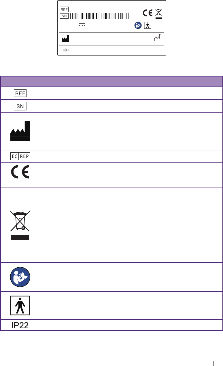
The following symbols provide information about the system’s labels and
regulatory compliance.
System label icons
X X X X X X X X X X
Diagnostic Ultrasound System
UH100
Power:19V 3.43A
FCC ID:VRSUH100N
Qisda Corporation
1, 5, 7F NO.159, Shan-Ying Road, Shan-Ting Li, Gueishan Dist.,
Taoyuan City,Taiwan, R.O.C.
Mednet Gmbh
Borkstrasse 10, 48163 Muenster, Germany Made in Taiwan
201X-XX
0120
IP22
Figure 1 System SPEC label for CE MDD Ver.20150925.01
Symbols Descriptions
Product model
Serial number
Manufacturer Mark
Manufacturer
Qisda Corporation manufactures the diagnostic ultrasound
system.
EU/EC European Authorised Representative
0120
CE marking certification with Notified Body number 0120
Dispose of Properly
Do not dispose of by dumping in garbage. Use a separate
collection for electrical and electronic equipment.
Products bearing this symbol are subject to the European
Community directive 2002/96/EC on waste electrical and
electronic equipment (WEEE), amended by directive 2003/108/
EC. For collection and disposal of the product, its components,
or its accessories, contact your local Qisda Corporation
representative.
Refer to the User Manual
This label indicates that the user should refer to the User
Manual for information on using this equipment.
Type BF Equipment Applied Part
The Qisda Diagnostic Ultrasound System provides protection
against electric shock.
IP Code, International Protection Marking
17
Safety information Warning symbols
Symbols Descriptions
201X-XX
Manufacturer date
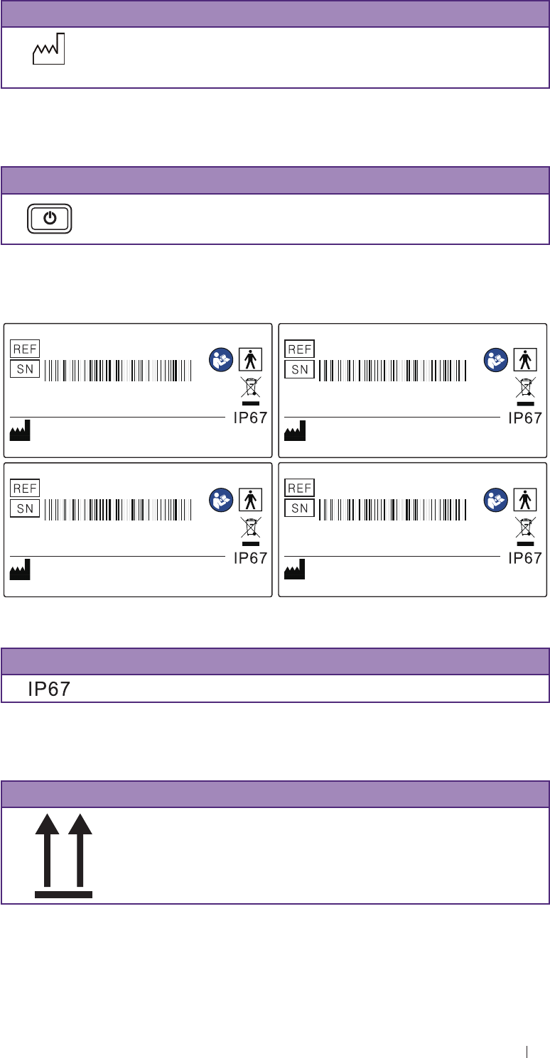
System button
Symbols Descriptions
Power button
Press and hold the Power button to turn on/off the system.
Transducer label icons
Ultrasound Transducer_Linear Array
L115A / 5~11MHZ
Qisda Corporation
1, 5, 7F NO.159, Shan-Ying Road, Shan-Ting Li,
Gueishan Dist.,Taoyuan City,Taiwan, R.O.C.
X X X X X X X X X X
Ultrasound Transducer_
Phased Array
P42A / 2~4MHz
Qisda Corporation
1, 5, 7F NO.159, Shan-Ying Road, Shan-Ting Li,
Gueishan Dist.,Taoyuan City,Taiwan, R.O.C.
X X X X X X X X X X
Ultrasound Transducer_
Curved Linear Array
C52A / 2~5MHz
Qisda Corporation
1, 5, 7F NO.159, Shan-Ying Road, Shan-Ting Li,
Gueishan Dist.,Taoyuan City,Taiwan, R.O.C.
X X X X X X X X X X
Ultrasound Transducer_
Endocavity Array
E94A / 4~9MHz
Caution: The surface heating limit of this transducer
shall be no more than 43˚C
Qisda Corporation
1, 5, 7F NO.159, Shan-Ying Road, Shan-Ting Li,
Gueishan Dist.,Taoyuan City,Taiwan, R.O.C.
X X X X X X X X X X
Figure 2 Transducer SPEC labels for CE MDD Ver.20150922.01
Symbols Descriptions
IP Code, International Protection Marking
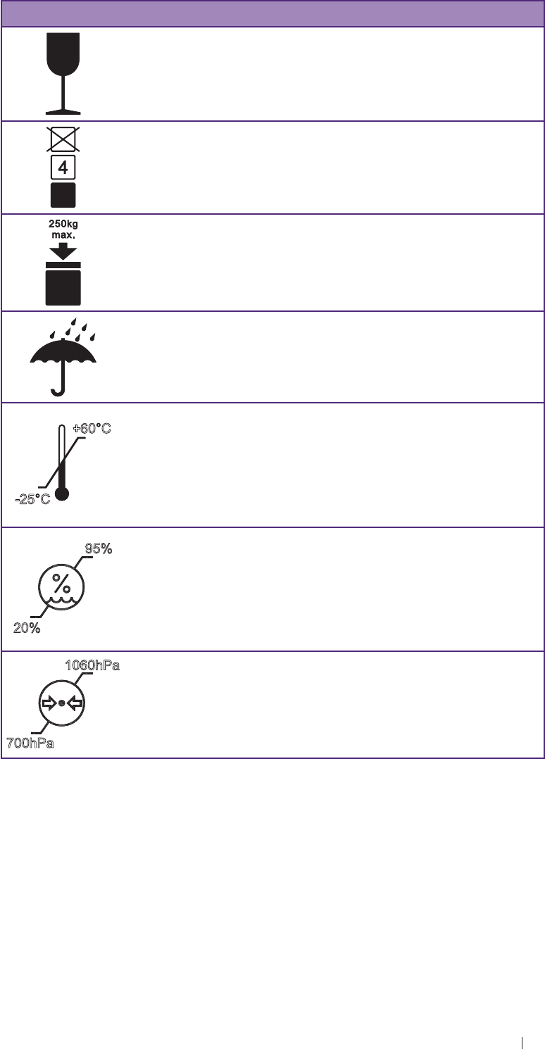
Shipping label icons
Symbols Descriptions
This Side Up
18
Safety information Electrical safety
Symbols Descriptions
Fragile
Maximum Stacking Height
Maximum Rated Load
Sun and Rain
-25°C
+60°C
Temperature
The Qisda Diagnostic Ultrasound System must be stored
in the original shipping container in environments between
-25°C and 60°C (-13°F and 140°F). The temperature while
operating the system should be kept between 10°C and
40°C (32°F and 104°F).
20%
95%
Humidity
The Qisda Diagnostic Ultrasound System must be stored
in the original shipping container in environments with 20%
to 95% relative humidity and non-condensing. The humidity
while operating the system should be kept between 20% to
85% relative humidity and non-condensing.
1060hPa
700hPa
Air Pressure
The Qisda Diagnostic Ultrasound System must be stored
in the original shipping container in environments between
700 hPa (525 mmHg) and 1060 hPa (795 mmHg) air
pressure.
Electrical safety
Only trained medical personnel should operate this system. This system
complies with the following standards:
19
Safety information Electrical safety
Electrical:
» IEC 60601-1:2005+AMD1:2012; EN 60601-1:2006+A11:2011+A
1:2013+A12:2014, Medical Electrical Equipment Part 1: General
Requirements For Safety, Class I, BF, continuous operation
» IEC 60601-2-37: 2007, Medical Electrical Equipment Part 2-37:
Particular Requirements For The Safety of Ultrasonic Medical
Diagnostic And Monitoring Equipment
EMC/EMI:
» IEC 60601-1-2:2007/AC:2010, CISPR 11 Group I Class B
Harmful liquid protection:
» For the main system: IP22
» For the transducer: IP67
» For maximum safety, observe the following guidelines strictly:
Shock hazards exist if the power adapter is damaged or is not
properly grounded. Use only the supplied medical grade power cord
and power adapter.
Do not remove or try to circumvent the grounding wire. If the
protective grounding of the system is questionable, disconnect the
system from the power source and run it on its internal battery.
Please plug the system into a hospital-grade, three-hole outlet, and
do not circumvent the power cord.
To avoid the risk of electric shock, the system must only be
connected to the mains power supply that incorporate protective
earth.
Only authorized service technicians can make internal replacements
of the system.
Do not operate the system in the presence of flammable gases.
Do not use a transducer if the transducer or cable is damaged.
Return damaged equipment to the Qisda dealer for replacement.
All peripheral devices connected to the system must comply with
IEC 60601 or IEC 60950-1.
Transducer cables have strain relief at terminations. Inspect cables
regularly to detect damaged, frayed, or broken cables that might
contact a patient.
E94A are invasive transducers. The operator should immediately
stop using the E94A transducer when its surface temperature
reaches 43°C.

20
Safety information Electrical safety
Battery usage/disposal
Do not disassemble the system.
Use only the supplied battery. Using an unapproved battery may
cause the system to explode and result in serious damage to your
health or property.
Do not replace, heat, crush, puncture, short external contacts, or
incinerate the battery.
Use only the supplied power adapter to charge the battery.
The system can contain environmentally hazardous materials such
as, but not limited to: heavy metals, general recyclable metals, and
plastics. This product should be recycled according to local and
national guidelines for recycling electronic equipment.
Incorrect use of the battery may cause a leak of chemicals or
explosion. The leak of chemicals may harm the skin. If any chemicals
leak from the device, use a dry cloth to wipe it clean and contact the
Qisda dealer for help.
Dispose of used batteries according to the instructions.
Electrical Fast Transients (EFT)
The system complies with the IEC 60601-1-2 3rd edition standard
for susceptibility to electrical fast transients (EFT) on the power line.
However, if the system experiences EFT on the power line, artifacts
(vertical lines, excessive noise in image, etc.) may appear on the
ultrasound image. To eliminate these artifacts caused by an EFT
condition, the operator should either:
Disconnect the system from the power source by unplugging the
power cord from the tablet, and run the system on its internal battery.
Or
Unplug the power cord from the wall and move to a different power
source that is not experiencing this condition.
Electromagnetic Interference (EMI)
Medical electrical equipment such as the system requires special
precautions regarding electromagnetic compatibility, and must be
installed and put into service according to the following electromagnetic
tables.

21
Safety information Electrical safety
All equipment
The UH100 is intended for use in the electromagnetic environment
specified below. The customer or operator of the UH100 should ensure
that it is used in such an environment.
Guidance and manufacturer’s declaration - Electromagnetic
emissions - All equipment
Emissions test Compliance Electromagnetic environment - Guidance
RF Emissions
CISPR 11 Group 1 The Qisda Diagnostic Ultrasound
System uses RF energy only for its
internal function. Therefore, its RF
emissions are very low and are not
likely to cause any interference in
nearby electronic equipment.
RF Emissions
CISPR 11 Class B The Qisda Diagnostic Ultrasound
System is suitable for use in all
establishments, including domestic, and
those directly connected to the public
low-voltage power supply network that
supplies buildings used for domestic
purposes.
Harmonics
IEC 61000-3-2 Class A or B
Flicker
IEC 61000-3-3 Complies
RF Emissions
CISPR 14-1 Complies The UH100 is not suitable for
interconnection with other equipment.
RF Emissions
CISPR 15 Complies The UH100 is not suitable for
interconnection with other equipment.
Guidance and manufacturer’s declaration - Electromagnetic
immunity - All equipment
Immunity test IEC 60601 test
level
Compliance
level
Electromagnetic
environment - Guidance
ESD
IEC 61000-4-2 ±6 kV Contact
±8 kV Air
As
specified Floors should be wood,
concrete or ceramic tile.
If floors are synthetic, the
relative humidity should be
at least 30%
EFT
IEC 61000-4-4 ±2 kV Mains
± 1kV I/Os
As
specified Mains power quality
should be that of a typical
commercial or hospital
environment.
Surge
IEC 61000-4-5 ±1 kV Differential
±2 kV Common
As
specified

22
Safety information Electrical safety
Immunity test IEC 60601 test
level
Compliance
level
Electromagnetic
environment - Guidance
Voltage dips/
Dropout
IEC 61000-4-11
>95% dip for 0.5
cycle
60% dip for
5 cycles
30% dip for
25 cycles
>95% dip for
5 seconds
As
specified Mains power quality
should be that of a typical
commercial or hospital
environment. If the user
of the UH100 requires
continued operation during
power mains interruptions,
it is recommended that the
UH100 be powered from
an uninterruptible power
supply or battery.
Power frequency
50/60 Hz
Magnetic field
IEC 61000-4-8
3 A/m As
specified Power frequency magnetic
fields should be that of
a typical commercial or
hospital environment.
Guidance and manufacturer’s declaration - Electromagnetic
immunity - Non-life-supporting equipment
Immunity test IEC 60601
test level
Compliance
level
Electromagnetic environment -
Guidance
Portable and mobile RF
communications equipment
should be used no closer to
any part of UH100, including
cables, than the recommended
separation distance calculated
from the equation applicable to
the frequency of the transmitter.
Recommended separation
distance
Conducted RF
IEC 61000-4-6
3 Vrms
150 KHz to
80 MHz
[V1] =
3 Vrms d = [ ] √P
3.5
V1
Radiated RF
IEC 61000-4-3
3 V/m
80 MHz to
2.5 GHz
[E1] =
3 V/m d = [ ] √P
3.5
E1 80 MHz to 800 MHz
d = [ ] √P
7
E1 800 MHz to 2.5 GHz

23
Safety information Electrical safety
Immunity test IEC 60601
test level
Compliance
level
Electromagnetic environment -
Guidance
Where P is the maximum output
power rating of the transmitter
in watts (W) according to the
transmitter manufacturer, and d
is the recommended separation
distance in meters (m).
Field strengths from fixed RF
transmitters, as determined
by an electromagnetic site
survey a, should be less than
the compliance level in each
frequency rangeb.
Interference may occur in the
vicinity of equipment marked with
the following symbol:
a Field strengths from fixed transmitters, such as base stations for radio
(cellular/cordless) telephones and land mobile radios, amateur radio, AM and
FM radio broadcast and TV broadcast cannot be predicted theoretically with
accuracy.
To assess the electromagnetic environment due to fixed RF transmitters,
an electromagnetic site survey should be considered. If the measured field
strength in the location in which UH100 is used exceeds the applicable
RF compliance level above, UH100 should be observed to verify normal
operation. If abnormal performance is observed, additional measures may be
necessary, such as reorienting or relocating UH100.
b Over the frequency range 150 kHz to 80 MHz, field strengths should be less
than 3 V/m.
Separation Distances
The UH100 is intended for use in the electromagnetic environment in
which radiated disturbances are controlled. The customer or operator of
the UH100 can help prevent electromagnetic interference by maintaining
a minimum distance between portable and mobile RF Communications
Equipment and the UH100 as recommended below, according to the
maximum output power of the communications equipment.

24
Safety information Electrical safety
Maximum
Output
Power of
Transmitter
Watts (W)
Separation Distance According to Frequency of Transmitter
Meters (m)
150 kHz to 80 MHz
3.5√P
V1
= D
80 MHz to 800 MHz
3.5√P
E1
= D
800 MHz to 2.5 GHz
7√P
E1
= D
0.01 0.12 m 0.12 m 0.24 m
0.1 0.37 m 0.37 m 0.74 m
1 1.17 m 1.17 m 2.34 m
10 3.69 m 3.69 m 7.38 m
100 11.67 m 11.67 m 23.34 m
Table 1 Separation distances
For transmitters rated at a maximum output power not listed above, the
recommended separation distance d in meters (m) can be estimated
using the equation applicable to the frequency of the transmitter, where
P is the maximum output power rate of the transmitter in watts (W)
according to the transmitter manufacturer.
At 80 MHz and 800 MHz, the separation distance for the higher
frequency range applies.
These guidelines may not apply in all situations. Electromagnetic
propagation is affected by absorption and reflection from structures,
objects and people.
Surges to mains power supply
If the system is powered from the mains power supply that could
experience surges above 1 kV (for example, from extreme lightning
conditions), additional surge suppression is recommended.
Electromagnetic Interference (EMI)
Medical electrical equipment such as the system requires special
precautions regarding electromagnetic compatibility, and must be
installed and put into service according to the electromagnetic tables.
To limit exposure to electromagnetic interference from nearby equipment
that can degrade image quality, you should operate the Qisda Diagnostic
Ultrasound System under EMI conditions that minimize power supply
transients, mechanical interactions, vibration, and thermal, optical, and
ionizing radiation.

25
Safety information RF safety
RF safety
The system should be operated in a location that is no closer than listed
in “Non-Life-Supporting Equipment” to any part of RF communications
equipment that may disturb its functions. If abnormal performance is
observed, additional measures may be necessary, such as re-orienting
or relocating the equipment. The system should be separated by at least
the distances specified in the table referenced above.
The system is intended for use in an electromagnetic environment where
radiated RF disturbances are controlled. The customer or the user of the
system can help prevent electromagnetic interference by maintaining
a minimum distance between portable and mobile RF communications
equipment (transmitters) and the system according to the maximum
output power of the communications equipment.
Biological safety
This product, as with all diagnostic ultrasound equipment, should be
used only for valid reasons and should be used both for the shortest
period of time and at the lowest power settings necessary (ALARA - As
Low As Reasonably Achievable) to produce diagnostically acceptable
images. The AIUM offers the following guidelines:
Clinical Safety Quoted from AIUM
Approved March 26, 1997
Diagnostic ultrasound has been in use since the late 1950s. Given its
known benefits and recognized efficacy for medical diagnosis, including
use during human pregnancy, the American Institute of Ultrasound in
Medicine herein addresses the clinical safety of such use.
There are no confirmed biological effects on patients or instrument
operators caused by exposures from present diagnostic ultrasound
instruments. Although the possibility exists that such biological effects
may be identified in the future, current data indicate that the benefits to
patients of the prudent use of diagnostic ultrasound outweigh the risks,
if any that may be present.

26
Safety information Biological safety
Heating
Elevating tissue temperature during obstetrical examinations creates
medical concerns. At the embryo development stage, the rise in
temperature and the length of time exposed to heat combine to
determine potential detrimental effects. Exercise caution, particularly
during Color Doppler imaging exams. The Thermal Index (TI) provides a
statistical estimate of the potential temperature elevation (in centigrade)
of tissue temperature. Three forms of TI are available: TIS, for soft tissue
exposures; TIB, for instances when bone lies near the beam focus; and
TIC, for the heating of bone situated close to the transducer.
Cavitation
Cavitation may occur when sound passes through an area that contains
a cavity, such as a gas bubble or air pocket (in the lung or intestine,
for example). During the process of cavitation, the sound wave may
cause the bubble to contract or resonate. This oscillation may cause the
bubbles to explode and damage the tissue. The Mechanical Index (MI)
has been created to help operators accurately evaluate the likelihood of
cavitation and the related adverse effects.
Safe scanning guideline
Ultrasound should only be used for medical diagnosis and only by
trained medical personnel.
Diagnostic ultrasound procedures should be done only by personnel
fully trained in the use of the system, in the interpretation of the
results and images, and in the safe use of ultrasound (including
education as to potential hazards).
Operators should understand the likely influence of the machine
controls, the operating mode (e.g. B mode, Color Doppler or
Spectral Doppler) and the transducer frequency on thermal and
cavitation hazards.
Use a low output power default setting for each new patient. Output
should only be increased during the examination if penetration is still
required to achieve a satisfactory result, and after the Gain control
has been adjusted to its maximum value.
Maintain the shortest examination time necessary to produce a useful
diagnostic result.
27
Safety information Biological safety
Take particular care to reduce output and minimize exposure
time of an embryo or fetus when the temperature of the mother is
already elevated.
Take particular care to reduce the risk of thermal hazard during
diagnostic ultrasound when exposing an embryo less than eight
weeks after gestation, or the head, brain or spine of any fetus or
neonate.
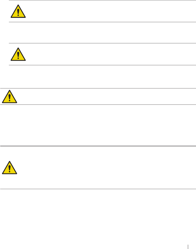
Do not use endocavity transducers if there is noticeable self-heating
of the transducer before insertion. If the following system message
displays during a real-time scan, cease the current scan.
Although applicable to any transducer, take particular care during
trans-vaginal exams during the first eight weeks of gestation.
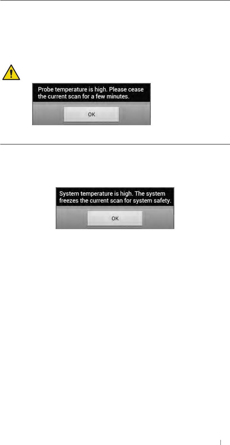
During continuous operation, the system temperature may become
too high. If the following system message displays during a real-time
scan, touch OK and the system enters frozen imaging screen. To
resume scanning, wait until the system engine cools down.
Operators should continually monitor the on-screen thermal index (TI)
and mechanical index (MI) values and use control settings that keep
these settings as low as possible while still achieving diagnostically
useful results. In obstetric examinations, TIS (soft tissue thermal
index) should be monitored during scans carried out in the first eight
weeks after gestation, and TIB (bone thermal index) thereafter. In
applications where the transducer is very close to bone (e.g. trans-
cranial applications), TIC (cranial thermal index) should be monitored.
MI> 0.3 Minor damage is likely to happen to neonatal lung or
intestine. If such exposure is necessary, reduce the
exposure time as much as possible.
MI> 0.7 Risk of cavitation exists if an ultrasound contrast agent
containing gas microspheres is being used. There is
a theoretical risk of cavitation without the presence of
ultrasound contrast agents. The risk increases with MI
values above this threshold.
TI> 0.7 The overall exposure time of an embryo or fetus should
be restricted in accordance with the following table as a
reference.

28
Safety information Waterproof and dustproof ratings
TI Maximum exposure time (minutes)
0.7 60
1.0 30
1.5 15
2.0 4
2.5 1
Table 2 Maximum exposure time recommended for an embryo or fetus
Diagnostic ultrasound has the potential for both false positive and
false negative results. Misdiagnosis is far more dangerous than any
effect that might result from the ultrasound exposure. Therefore,
diagnostic ultrasound should be performed only by those with
sufficient training and education.
Non-diagnostic use of ultrasound equipment is not generally
recommended. Examples of non-diagnostic uses of ultrasound
equipment include repeated scans for operator training, equipment
demonstration using normal subjects, and the production of souvenir
pictures or videos of a fetus. For equipment of which the safety
indices are displayed over their full range of values, the TI should
always be less than 0.5 and the MI should always be less than 0.3.
Avoid frequent repeated exposure of any subject. Scans in the first
trimester of pregnancy should not be carried out for the sole purpose
of producing souvenir videos or photographs, nor should their
production involve increasing the exposure levels or extending the
scan times beyond those needed for clinical purposes.
Temperature display for transducers intended for internal
use
For E94A transducers used for internal applications, e.g. the endocavity
transducers, the transducer tip temperature is displayed on the screen.
To protect the patient against the harm of excessive temperature, the
system automatically turns off the transducer when the transducer
temperature reaches a threshold temperature.
Waterproof and dustproof ratings
The system has a degree of protection from ingress of water and
particulate matter, but the tablet is not approved for use where it would
be exposed to liquids. If it is used in environments where it might be
exposed to liquids, the tablet must be covered by ad drape, such as s
a Civco #610-1037. These environments include, but are not limited to
outpatient and private office procedures such as biopsies, office visits,
and other traditional, non-invasive scanning.
29
Safety information Understand the MI/TI display
The following table lists the applied parts and their levels of protection.
Component Manufacturer Use IP level
Diagnostic
Ultrasound System Qisda
Corporation Ultrasound system IP22
C52A transducer Qisda
Corporation Ultrasound
transducer IP67 (at
transducer head)
L115A transducer Qisda
Corporation Ultrasound
transducer IP67 (at
transducer head)
P42A transducer Qisda
Corporation Ultrasound
transducer IP67 (at
transducer head)
E94A transducer Qisda
Corporation Ultrasound
transducer IP67 (at
transducer head)
Power adapter Adapter
Technology Co.,
Ltd.
Power source and
battery charger for
ultrasound system
Power cord
I-SHENG
ELECTRIC
WIRE & CABLE
CO. LTD.
AC line cord
Table 3 Waterproof and dustproof ratings
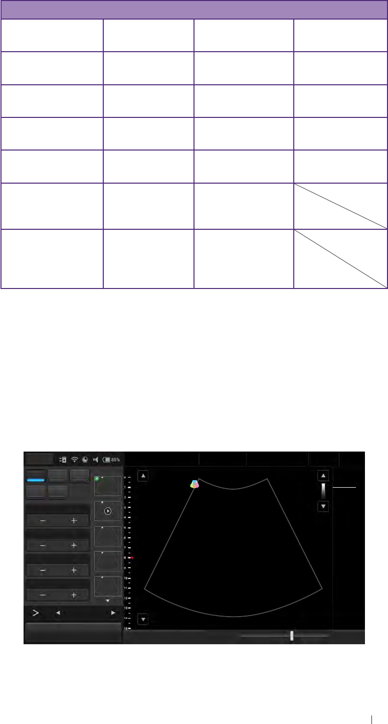
Understand the MI/TI display
The system allows full software control of acoustic output. When
powering on the system or create a new exam, scan parameters should
be set to default preset. All of the default presets are compliant with IEC
60601-2-37 track 3. Both scan parameters and TI/MI information are
real-time display in the scan properties area.
Menu Adam, Smith
1234567
27 01/01/1988
Liver
09/03/2015 02:56PM
Dr. Smith
Medical
Center
BColor PW TI 0.11
MI 0.92
CLA
M Power 0Gn 58
15.0cm 15FPS
1/ 1
M/ 80.0
60/ 0
0/ 4
B Gain 58
Depth 15.0
Focus 8.0
DYN Range 60
12
B Function
Freeze Save Image Fun.Key Tuning TGC Penetration Resolution End Exam
Figure 3 MI/TI on-screen display format

30
Safety information Understand the MI/TI display
For transducer/mode combinations marked “V”, the MI or TI index is
equal or greater than 1.0.
Mode /
Transducer
C52A Curved
Linear Array
2-5 MHz
L115A
Linear Array
5-11 MHz
P42A Phased
Array 80
elements
2-4 MHz
E94A Micro
Curved
Linear Array
4-9MHz
B‒‒‒‒
B/M ‒‒‒‒
THI, B (TBD) (TBD) (TBD) (TBD)
THI, B/M (TBD) (TBD) (TBD) (TBD)
PW ‒‒‒‒
CFM-B ‒ ‒ V‒
CFM-THI, B (TBD) (TBD) (TBD) (TBD)
Table 4 MI/TI generating from applicable transducer/mode combinations
Track-3 follows the Output Display Standard for systems which include
fetal Doppler applications. The acoustic output will not be evaluated on
an application-specific basis, but the global maximum de-rated Ispta
must be ≤ 720 mW/cm2 and either the global maximum MI must be
≤ 1.9, or the global maximum de-rated Isppa must be ≤ 190 W/cm2. An
exception is for ophthalmic use, in which case the TI=max (TIS, TIC) is
not to exceed 1.0; Ispta.3 ≤ 50 mW/CM2, and MI ≤ 0.23. Track-3 gives
the operator the freedom to increase the output acoustic power for a
specific exam, and still limit output acoustic power within the global
maximum de-rated Ispta ≤ 720 mW/cm2 under an Output Display
Standard.
The increments are for the display of thermal indices, if displayed is
no more than 0.2 for values of indices up to 2.0 and 0.5 for values of
indices above 2.0. The system design allows full software control of
the acoustic output, entry of new patient identification data or change
from a non-foetal to a foetal application, and the system may switch to
an appropriate default setting upon powering on. These default setting
levels are established before shipping and may be reconfigured by the
operator.

31
Safety information Understand the MI/TI display
For any diagnostic ultrasound systems, Track-3 provides an Output
Indices Display Standard. The diagnostic ultrasound systems and its
User Manual contain the information regarding an ALARA (As Low
As Reasonably Achievable) education program from the clinical end-
user and the acoustic output indices, MI and TI. The MI describes
the likelihood of cavitation, and the TI offers the predicted maximum
temperature rise in tissue as a result of the diagnostic examination. In
general, a temperature increase of 2.5°C must be present consistently at
one spot for 2 hours to cause possible fetal abnormalities. Avoiding a local
temperature rise above 1°C should ensure that no thermally induced
biologic effect occurs. When referring to the TI for potential thermal
effect, a TI equal to 1 does not mean the temperature will rise 1°C. It only
means an increased potential for thermal effects can be expected as the
TI increases. A high index does not mean that bioeffects are occurring,
but only that the potential exists and there is no consideration in the TI
for the scan duration, so minimizing the overall scan time will reduce
the potential for effects. These operator control and display features
move the safety responsibility from the manufacturer to the operator. So
it is very important to have the diagnostic ultrasound systems display
the acoustic output indices correctly and the well-educated operator to
interpret the value appropriately.
RF: De-rating factor
In Situ intensity and pressure cannot currently be measured. Therefore,
the acoustic power measurement is normally done in the water tank, and
when soft tissue replaces water along the ultrasound path, a decrease
in intensity is expected. The fractional reduction in intensity caused by
attenuation is denoted by the de-rating factor (RF),
RF = 10 (-0.1 a∙f∙z)
Where a is the attenuation coefficient in dB cm-1 MHz-1, f is the
transducer center frequency, and z is the distance along the beam axis
between the source and the point of interest.
De-rating factor RF for the various distances and frequencies with
attenuation coefficient 0.3 dB cm-1 MHz-1 in homogeneous soft tissue is
listed in the following table. An example is if the operator uses 7.5 MHz
frequency, the power will be attenuated by .0750 at 5 cm, or 0.3 x 7.5 x
5 = -11.25 dB. The De-rated Intensity is also referred to as ‘.3’ at the end
(e.g. Ispta.3).
Distance (cm) Frequency (MHz)
1 3 5 7.5
1 0.9332 0.8128 0.7080 0.5957
2 0.8710 0.6607 0.5012 0.3548
3 0.8128 0.5370 0.3548 0.2113

32
Safety information Understand the MI/TI display
Distance (cm) Frequency (MHz)
1 3 5 7.5
4 0.7586 0.4365 0.2512 0.1259
5 0.7080 0.3548 0.1778 0.0750
6 0.6607 0.2884 0.1259 0.0447
7 0.6166 0.2344 0.0891 0.0266
8 0.5754 0.1903 0.0631 0.0158
Table 5
I’ = I * RF Where I’ is the intensity in soft tissue, I is the time-
averaged intensity measured in water.
Tissue model
Tissue temperature elevation depends on power, tissue type, beam
width, and scanning mode. Six models are developed to mimic possible
clinical situations.
Thermal
models Composition Mode Specification Application
type
1 TIS Soft tissue Unscanned Large aperture
(> 1 cm2)Liver PW
2 TIS Soft tissue Unscanned Small aperture
(< 1 cm2)Pencil
transducer
3 TIS Soft tissue Scanned Evaluated at
surface Breast color
4 TIB Soft tissue
and bone Scanned Soft tissue at
surface Muscle color
5 TIB Soft tissue
and bone Unscanned Bone at focus Fetus head
PW
6 TIC Soft tissue
and bone Unscanned /
Scanned Bone at
surface Trans-cranial
Table 6
Soft tissue
Describes low fat content tissue that does not contain calcifications or
large gas-filled spaces.
Scanned (auto-scan)
Refers to the steering of successive burst through the field of view, e.g.
B and Color mode.

33
Safety information Understand the MI/TI display
Unscanned
Emission of ultrasonic pulses occurs along a single line of sight and is
unchanged until the transducer is moved to a new position. For instance,
the PW and M mode.
TI
TI is defined as the ratio of the In Situ acoustic power (W.3) to the
acoustic power required to raise tissue temperature by 1°C (Wdeg),
TI = W.3 / Wdeg
Three TIs corresponding to soft tissue (TIS) for abdominal; bone (TIB)
for fetal and neonatal cephalic; and cranial bone (TIC) for pediatric and
adult cephalic, have been developed for applications in different exams.
An estimate of the acoustic power in milliwatts necessary to produce a
1°C temperature elevation in soft tissue is:
Wdeg = 210 / fc
For model 1 to 4, where fc is the center frequency in MHz.
Wdeg = 40 · K · D
For model 5 and 6, where K (beam shape factor) is 1.0, D is the aperture
diameter in cm at the depth of interest.
MI
Cavitation is more likely to occur at high pressures and low frequencies
in pulse ultrasound wave in the tissue, which contains a bubble or
air pocket (for instance, the lung, intestine, or scan with gas contrast
agents). The threshold under optimum conditions of pulsed ultrasound
is predicted by the ratio of the peak pressure to the square root of the
frequency.
MI = Pr’ / sqrt(fc)
Pr’ is the de-rated (0.3) peak rare-fractional pressure in Mpa at the point
where PII is the maximum, and fc is the center frequency in MHz. PII is
the Pulse Intensity Integral that the total energy per unit area carried by
the wave during the time duration of the pulse. The peak rare-fractional
pressure is measured in hydrophone maximum negative voltage
normalized by the hydrophone calibration parameter.

34
Safety information Transducer surface temperature rise
Display guideline
For different operation modes, different indices must be displayed.
However, only one index needs to be shown at a time. Display is not
required if maximum MI is less than 1.0 for any setting of the operating
mode, or if maximum TI is less than 1.0 for any setting of the operating
mode. For TI, if the TIS and TIC are both greater than 1.0, the scanners
need not be capable of displaying both indices simultaneously. If the
index falls below 0.4, no display is needed. The display increments are
no greater than 0.2 for index value less than one and no greater than 1.0
for index values greater than one (e.g. 0.4, 0.6, 0.8, 1.2, 3).
Display and report in different modes
For B mode
Display and report only MI, and start from 0.4 if maximum MI > 1.0
For Color mode
Display and report only TIS or TIB, and start from 0.4 if maximum TI > 1.0
For Doppler mode
Display and report only TIS or TIB, and start from 0.4 if maximum TI > 1.0
Below is a simple guideline for the operator when TI exceeds one
limit exposure time to 4(6-TI) minutes based on the ‘National Council
on Radiation Protection. Exposure Criteria for Medical Diagnostic
Ultrasound: I. Criteria Based on Thermal Mechanisms. Report No.113
1992’.
Operator control features
The operator should be aware that certain operator controls may affect
the acoustic output. It is recommended to use the default (or lowest)
output power setting and compensate using Gain control to acquire
an image. Other than the output power setting in the Soft Menu, which
has the most direct impact on the power; the PRF (Pulse Repetition
Frequency), image sector size, frame rate, depth, and focal position also
slightly affect the output power. The default setting is normally around
70% of the allowable power, depending on the exam type.
Transducer surface temperature rise
The table below lists the measured surface temperature rise from
ambient (23°C ± 3°C) of transducers used on the system. The
temperatures were measured in accordance with EN 60601-2-37
cl.201.11 and cl.201.13 with controls and settings positioned to give
maximum temperatures.

35
Safety information Intended use
Test External use
(°C)
Non-external
Use (°C)
C52A P42A L115A E94A
Simulated use 1.5 1.4 3.0 1.9
Still air 7.3 3.6 6.5 3.3
Table 7 Transducer surface temperature rise
Intended use
The system is designed for use as a diagnostic tool and should only
be operated by someone who has received proper training in the use
and operation of a diagnostic ultrasound system. This system produces
images derived from sound echoes; those images must be interpreted by
a qualified medical professional. This system in no way interprets these
images or provides a medical diagnosis of the patient being examined.
The system has successfully completed compliance tests for IEC 60601-
1:2005 3rd ed., IEC 60601-1-2:2007 3rd ed., IEC 60601-2-37:2007
2nd ed. medical standards for the configuration as originally installed.
To maintain compliance with the stated safety and EMI standards,
we recommends use of medical grade peripherals only. Use of non-
medical grade peripherals will result in non-compliance of safety and
EMI standards. Non-conformance to these standards can produce risks
to the patient and operator of this equipment. We cannot be held liable
for changes to the system topology that no longer conform to the stated
safety and EMI standards. Changes to the system topology may make
it necessary to retest the complete system for compliance to these
standards. The User Manual refers to the potential for connecting the
system to peripherals such as VCRs, TVs, and printers. Note that we
have not performed compliance tests to the stated standards with these
types of devices connected to the system. Any peripheral device, such
as a network connection, etc. connected to the system must conform to
the IEC standards outlined above (i.e., IEC 60601-1:2005 3rd ed., IEC
60601-1-2:2007 3rd ed., and IEC 60601-2-37:2007 2nd ed.)
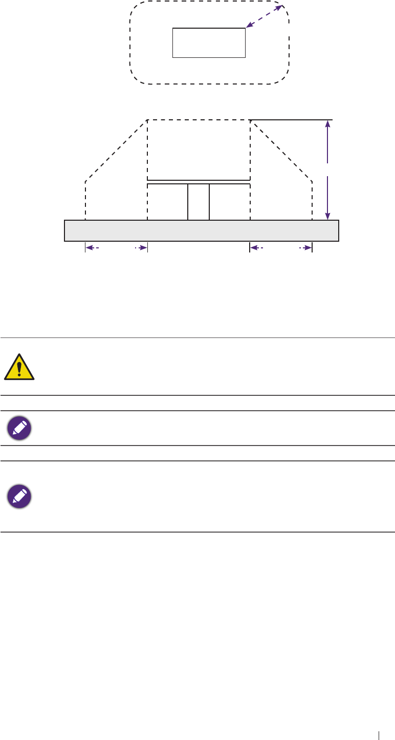
The system (without peripherals) is suitable for use within the patient
environment, as defined by the following:
The user should never simultaneously make contact with the
patient and the inside of any equipment where a protective cover
of any kind is removed. This includes the protective covers for the
transducer holders containing the ultrasound transducer and power
modules located at the patient table.
When using E94A endocavity transducers, the transducers must be
protected with a transducer sheath.
36
Safety information Intended use
The patient environment is defined as shown in the following figure.
Patient table
1.50 m
2.50 m
1.50 m
Overhead view
Side view
1.50 m
Figure 4 Patient environment
Portable and mobile RF communications equipment can affect medical
electrical equipment such as the system and should not be used in the
patient environment.
The system should not be used adjacent to or stacked with other
equipment. If adjacent or stacked use is necessary, the system should
be observed to verify normal operation in the configuration in which it
will be used.
If there is a certain frequency of image interference, there is a need of
isolation or filtering of the RF signal.
If the system is interfered by power or signal cable, the image
quality may be reduced or abnormally displayed. Such kind of
interfered images could easily be identified and differentiated from
the physiological characteristics of patient and longer clinical time
consumed but wouldn’t have any diagnostic accuracy issue.

37
Safety information Indications for use
Indications for use
The following tables provide Diagnostic Ultrasound Indications for Use
forms for the transducers offered with the Qisda Diagnostic Ultrasound
System.
DIAGNOSTIC ULTRASOUND INDICATIONS FOR USE FORM
System: UH100 Diagnostic Ultrasound System
Transducer: C52A (2-5 MHz Curved Linear Array R=50 mm)
Intended Use: Diagnostic ultrasound imaging or fluid flow analysis of the
human body as follows:
Clinical application Mode of operation
General
(Track 1
only)
Specific
(Track 1
and 3)
B M PWD Color
Doppler Power
Doppler Comb
Modes*
Tissue
Harmonic
Imaging
Fetal
imaging
and
others
Fetal X X X X X Note 1 X
Abdominal X X X X X Note 1 X
Small organ
(thyroid,
breast, etc.)
Pediatric
Neonatal
cephalic
Adult
cephalica
Musculo-
skeletal
(Conven.)
Musculo-
skeletal
(Superficial)
Other (Ob/
Gyn) X X X X X Note 1 X
Cardiac
Cardiac
adult
Cardiac
pediatric
Other
(specify)
Peripheral
vessel Peripheral
vessel
Other
(specify)
*Combined modes include: B/M; B/PW; B/Color Doppler; B/Power
Doppler; B/Color Doppler/PWD and B/Power Doppler/PWD

38
Safety information Indications for use
DIAGNOSTIC ULTRASOUND INDICATIONS FOR USE FORM
System: UH100 Diagnostic Ultrasound System
Transducer: L115A (5-11 MHz Linear Array)
Intended Use: Diagnostic ultrasound imaging or fluid flow analysis of the
human body as follows:
Clinical application Mode of operation
General
(Track 1
only)
Specific
(Track 1
and 3)
B M PWD Color
Doppler Power
Doppler Comb
Modes*
Tissue
Harmonic
Imaging
Fetal
imaging
and
others
Fetal
Abdominal
Small organ
(thyroid,
breast, etc.) X X X X X Note 1 X
Pediatric
Neonatal
cephalic
Adult
cephalica
Musculo-
skeletal
(Conven.) X X X X X Note 1 X
Musculo-
skeletal
(Superficial) X X X X X Note 1 X
Other (Ob/
Gyn)
Cardiac
Cardiac
adult
Cardiac
pediatric
Other
(specify)
Peripheral
vessel Peripheral
vessel X X X X X Note 1 X
Other
(specify)
*Combined modes include: B/M; B/PW; B/Color Doppler; B/Power
Doppler; B/Color Doppler/PWD and B/Power Doppler/PWD

39
Safety information Indications for use
DIAGNOSTIC ULTRASOUND INDICATIONS FOR USE FORM
System: UH100 Diagnostic Ultrasound System
Transducer: P42A (2-4 MHz Phased Array)
Intended Use: Diagnostic ultrasound imaging or fluid flow analysis of the
human body as follows:
Clinical application Mode of operation
General
(Track 1
only)
Specific
(Track 1
and 3)
B M PWD Color
Doppler Power
Doppler Comb
Modes*
Tissue
Harmonic
Imaging
Fetal
imaging
and
others
Fetal
Abdominal X X X X X Note 1 X
Small organ
(thyroid,
breast, etc.)
Pediatric
Neonatal
cephalic
Adult
cephalica
Musculo-
skeletal
(Conven.)
Musculo-
skeletal
(Superficial)
Other (Ob/
Gyn)
Cardiac
Cardiac
adult X X X X X Note 1 X
Cardiac
pediatric X X X X X Note 1 X
Other
(specify)
Peripheral
vessel Peripheral
vessel
Other
(specify)
*Combined modes include: B/M; B/PW; B/Color Doppler; B/Power
Doppler; B/Color Doppler/PWD and B/Power Doppler/PWD

40
Safety information Indications for use
DIAGNOSTIC ULTRASOUND INDICATIONS FOR USE FORM
System: UH100 Diagnostic Ultrasound System
Transducer: E94A (4-9 MHz Micro-curved Linear Array)
Intended Use: Diagnostic ultrasound imaging or fluid flow analysis of the
human body as follows:
Clinical application Mode of operation
General
(Track 1
only)
Specific
(Track 1
and 3)
B M PWD Color
Doppler Power
Doppler Comb
Modes*
Tissue
Harmonic
Imaging
Fetal
imaging
and
others
Fetal X X X X X Note 1 X
Abdominal
Small organ
(thyroid,
breast, etc.)
Pediatric
Neonatal
cephalic
Adult
cephalica
Trans-rectal X X X X X Note 1 X
Trans-
vaginal X X X X X Note 1 X
Trans-
urethral
Trans-
esophageal
(non-Card)
Musculo-
skeletal
(Conven.)
Musculo-
skeletal
(Superficial)
Other (Ob/
Gyn) X X X X X Note 1 X
Cardiac
Cardiac
adult
Cardiac
pediatric
Other
(specify)
Peripheral
vessel Peripheral
vessel
Other
(specify)
*Combined modes include: B/M; B/PW; B/Color Doppler; B/Power
Doppler; B/Color Doppler/PWD and B/Power Doppler/PWD
41
Get Started System overview
3 Get Started
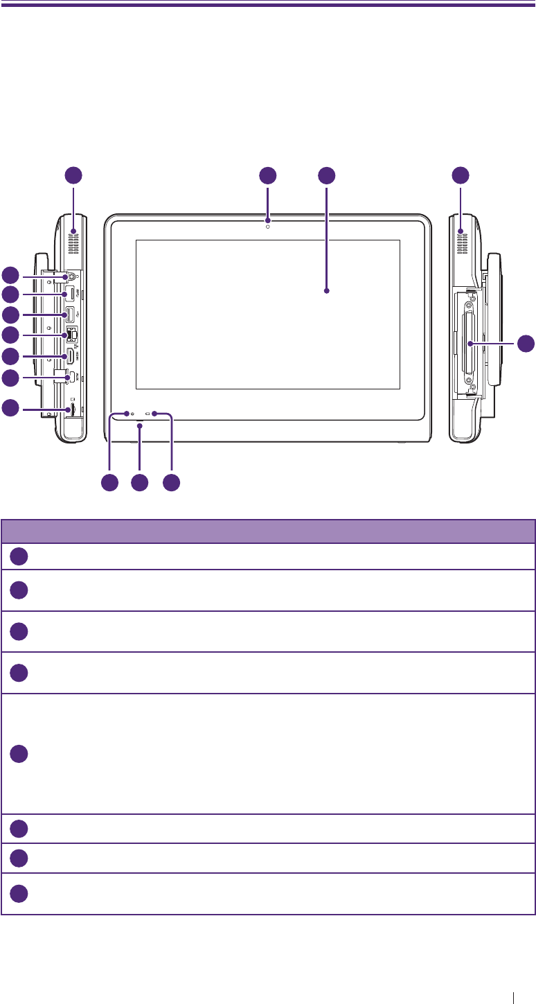
System overview
Front and side views
4
6 5
7
9
10
11
8
12
13
14
1233
No. Item Function
1
Camera lens Used to take pictures or record videos.
2
Touchscreen Display system information and allows you to
perform operations using different gestures.
3
Speakers Built-in speakers for playing sounds, which are
software-controlled.
4
Transducer
connection socket Connect a transducer to the system.
5
Battery indicator
When the system is connected to power:
Steadily on orange when the battery is charging.
Steadily on green after the battery is charged.
When the system is connected to power:
Steadily on orange when the battery is charging.
Steadily on green after the battery is charged.
6
Microphone Used for voice recording.
7
Power indicator Blink blue after the system enters Sleep mode.
8
MicroSD card slot Insert a microSD card into the microSD card slot to
access files stored in the card.
42
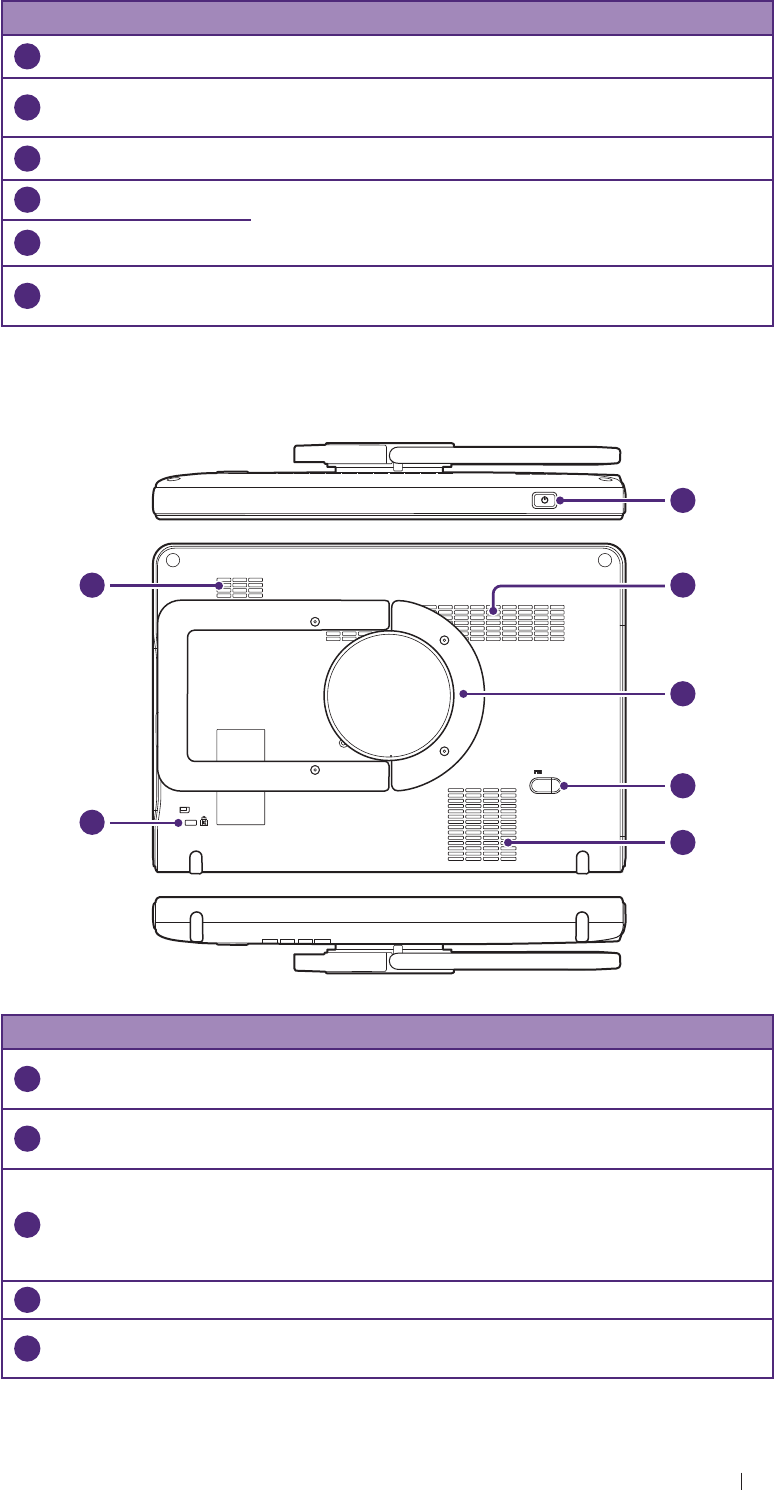
Get Started System overview
No. Item Function
9
AUX port Services only
10
HDMI port Connect the system to an HDMI (High-Definition
Multimedia Interface) device.
11
Ethernet socket Connect the system to an Ethernet-based network.
12
USB 2.0 port Connect the system to USB 2.0/3.0 devices, such
as keyboards, pointing devices, cameras or portable
storage devices.
13
USB 3.0 port
14
Headphone jack Connect the system to an audio device, such as
headphones or speakers.
Rear and top/bottom views
19
15
16
17
18
16
16
No. Item Function
15
Power button Press and hold the Power button to turn on/off the
system.
16
Ventilation slots Release excessive heat during operation to keep
the system in a safe operating temperature.
17
Rotating stand
Pull the rotating stand out to sustain the system
on a flat surface.
Can be used as a handle to carry the system
around.
18
Power input socket
19
Anti-theft lock slot Used to lock the system securely to a solid surface
to protect it from theft.
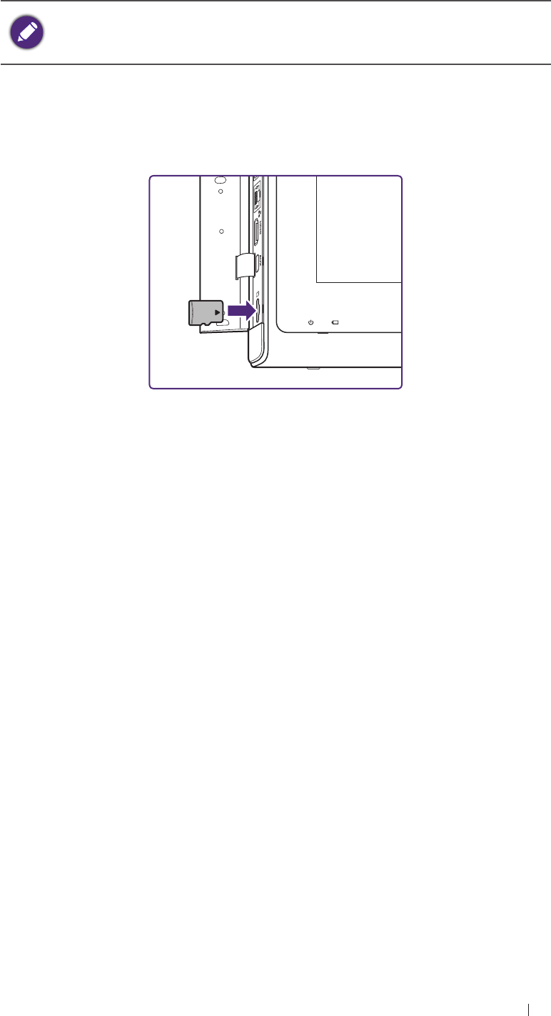
43
Get Started Insert a microSD card (optional)
Insert a microSD card (optional)
The system supports microSD cards (formatted in FAT32 only) up
to 64 GB in size.
The microSD card is available only by separate purchase.
1. Align the microSD card with the mark next to the microSD card slot.
2. Fully insert the microSD card into the card slot until it clicks into
place.
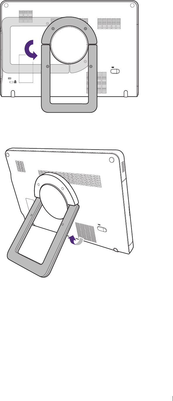
44
Get Started Use the stand
Use the stand
1. Rotate the rotating stand counterclockwise by 90 degree.
2. Gently pull out the rotating stand to the degree that suits your
preferred viewing angle.
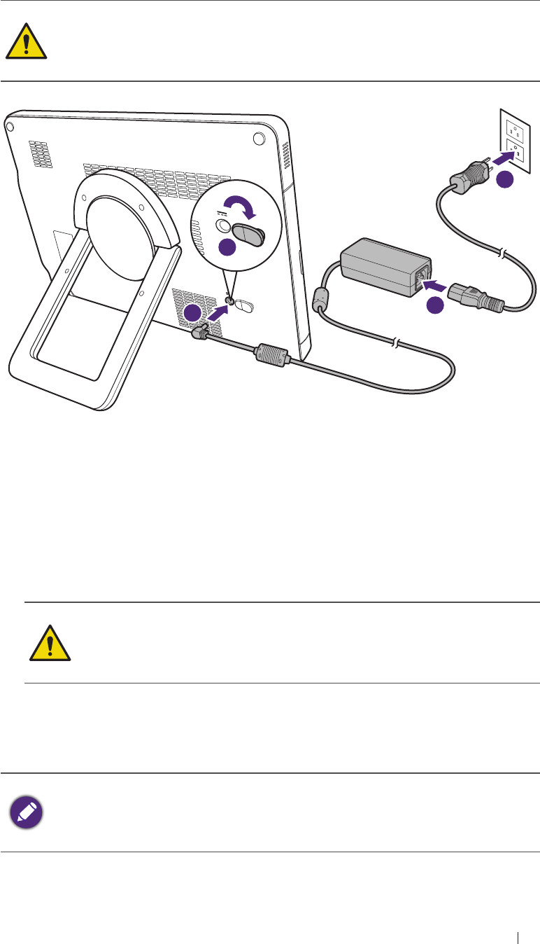
45
Get Started Charge the system
Charge the system
The system is only partially charged when first unpacked. Charge the
battery fully for 3 hours before using the system for the first time.
Use only the supplied power adapter and power cord for charing.
Do not try to repair or replace the battery or the power adapter. Any
attempt to disassemble the system and the supplied accessories
may cause damage to the system or result in personal injury.
3
1
2
4
1. Lift the protective rubber cover open.
2. Insert the supplied power cord’s connector into the power adapter.
3. Connect the power adapter’s connector into the system’s power input
socket.
4. Plug the power cord’s three-wire grounding plug into an electric outlet
to start charging. The battery indicator lights up in solid orange.
Keep good ventilation during charging. Do not cover the power
adapter with paper or objects that will reduce cooling.
Do not interrupt the connection during charging to avoid
possible damage.
5. After the battery is fully charged, the battery indicator turns green.
Remove the power adapter and the power cord from both the power
outlet and the system.
If the system is not in use for a long time, the battery will completely
run out and may not be powered on immediately even when it is
connected to power. When this occurs, fully charge the system for 3
hours before use.
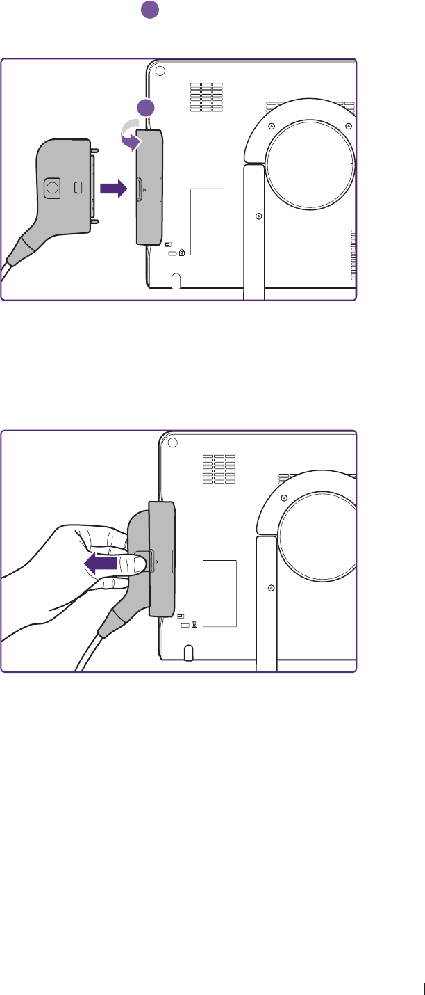
46
Get Started Connect the transducer
Connect the transducer
Flip the transducer cover open
a
and insert the transducer carefully into
the transducer connection socket until it is locked in place.
a
Remove the transducer
Press and hold the release latch, and carefully pull out the transducer.
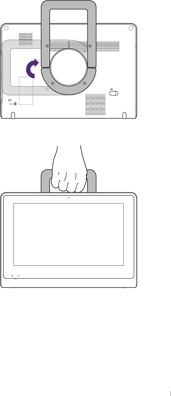
47
Get Started Use the system on the go
Use the system on the go
1. Rotate the rotating stand clockwise by 90 degree.
2. Use the rotating stand as a handle to carry the system around.
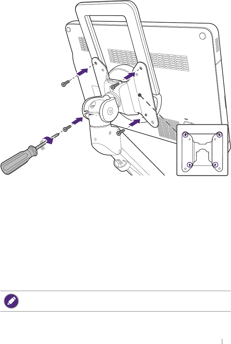
48
Get Started Wall-mount the system
Wall-mount the system
The hole pattern on the rear side of the system is compliant with VESA
standard. Therefore, the operator can install the system on any VESA
wall mounts, desktop or ceiling mounts.
1. Hold the system firmly and position it precisely to the front of the
mount plate where the hole patterns on both the back of the system
and the plate meet.
2. Hold an appropriate screwdriver and carefully drive four screws to
tighten the system with the mount plate.
100 mm
75 mm
Output the system display to an HDMI-enabled TV
or monitor
1. Insert one end of an HDMI cable to the system’s HDMI port. Ensure
that the arrow side faces up.
2. Insert the other end of the HDMI cable to your HDMI-enabled TV’s or
monitor’s HDMI port.
3. On the TV or monitor, select the proper input source.
Refer to the documentation of your HDMI-enabled television or
monitor for detailed connections and settings.

49
Basic operations Turn on the system
4 Basic operations
To conduct an ultrasound exam, complete the general procedure:
1. Connect the transducer (See page 46).
2. Turn on the system (See page 49).
3. Add a new patient (Patient screen), or load a work list (Work list
screen).
4. Select an exam type and preset (Preset screen).
5. Start real-time imaging (Imaging screen (Real-time)).
6. Set the transducer orientation (See page 60).
7. Select a scan mode and adjust image controls (See page 70).
8. When the desired anatomy is shown, freeze the image (See
page 62).
9. Add annotations or measurements (Imaging screen (Frozen)).
10. Save or print the image (See page 66).
11. (Optional) Review the images (See page 67), generate a report
and export the exam (See page 69).
12. End the exam (See page 69).
Please refer to the following sections for detailed instructions.
Turn on the system
Press and hold the Power button.
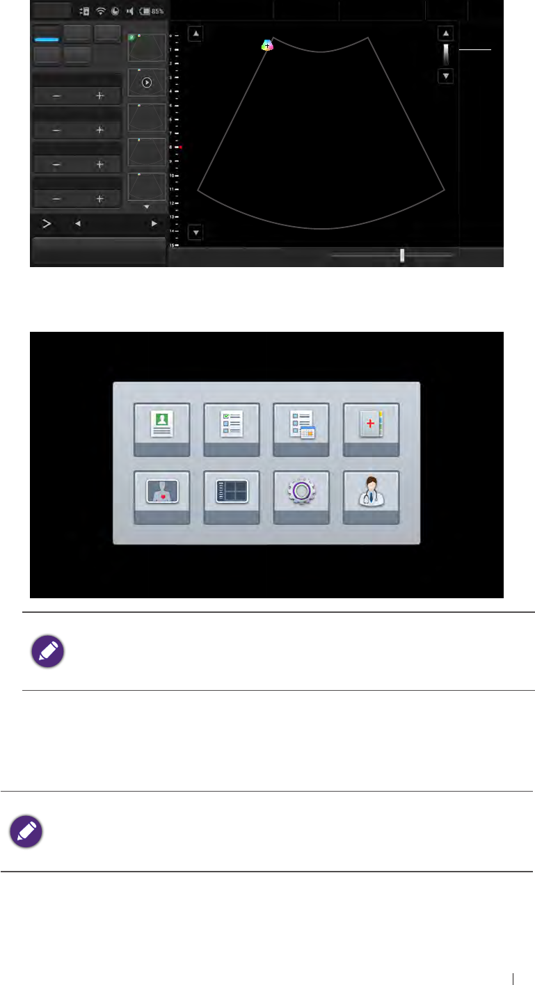
50
Basic operations Turn on the system
If a transducer is connected, the system enters the imaging screen in
B-mode after system startup.
Menu Adam, Smith
1234567
27 01/01/1988
Liver
09/03/2015 02:56PM
Dr. Smith
Medical
Center
BColor PW TI 0.11
MI 0.92
CLA
M Power 0Gn 58
15.0cm 15FPS
1/ 1
M/ 80.0
60/ 0
0/ 4
B Gain 58
Depth 15.0
Focus 8.0
DYN Range 60
12
B Function
Freeze Save Image Fun.Key Tuning TGC Penetration Resolution End Exam
If no transducer is connected, the system enters the system menu
screen after system startup.
No probe is connected
Patient Work list Exam history Report
Preset Review Setting User
If a transducer is connected and the system displays the message
“No probe is connected”, remove and then re-connect the
transducer. If the system still cannot detect the transducer, turn off
the system. Wait for a few seconds and restart the system.
To turn off the system
Press and hold the Power button until the pop-up menu appears on the
screen. Touch Power off > OK.
If the system does not respond to any operations, press and hold
the Power button to forcefully turn off the system.
If the system is turned off abnormally, powering on the system the
next time will take longer than usual for a system hardware check.
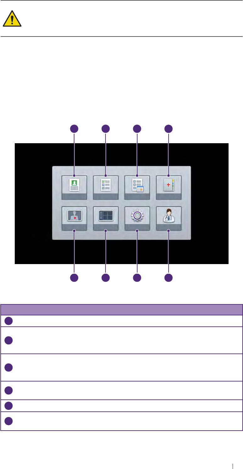
51
Basic operations Identify the main screen layout
Do not connect the system to any external drives until the startup
process completes to avoid damage or loss of data.
If an error message occurs after system startup, turn off the system
immediately and contact the service technician for help.
Identify the main screen layout
System menu screen
Touch Menu to display the following system menu screen. Touch an
icon to perform its function.
Patient Work list Exam history Report
Preset Review Setting User
1
2
3
4
5
6
7
8
Figure 5 System menu screen
No. Function Description
1
Patient Edit current or add new patient information.
2
Work list Load the DICOM Modality Worklist (MWL) that contains
patient information as well as the requested procedure
electronically via the MWL query.
3
Exam
history
View a list of patients with their exam results. The operator
can proceed with unfinished exams/reviews, or export exams
according to the selection criteria all at once.
4
Report Display exam information including patient data, exam type,
study specific data, comments and saved ultrasound images.
5
User Edit current or add new users.
6
Setting Set up and customize the system based on the operator’s
habitual needs.
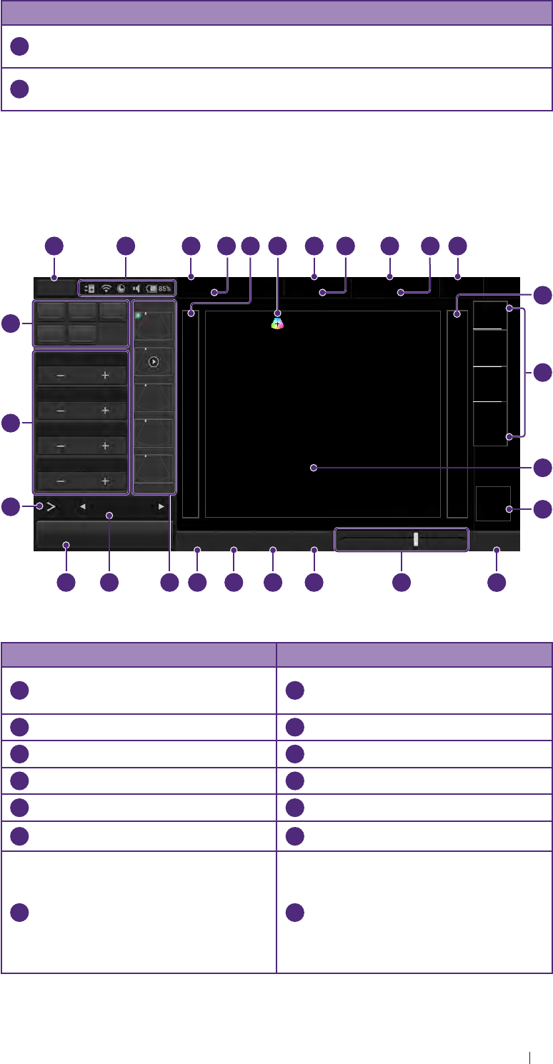
52
Basic operations Identify the main screen layout
No. Function Description
7
Review View, add annotations and measurements to, and export a
saved exam.
8
Preset Select the predefined preset compatible with the connected
transducer for optimized image control settings.
Imaging screen (Real-time)
With the transducer connected correctly, the system automatically enters
the real-time imaging screen after starting the ultrasound software.
10
1
2
4
6
7
8
9
3
5
13
16
17
15
18
19
20
21
22
23
11
12
14
24
25
26
27
Menu Adam, Smith
1234567
27 01/01/1988
Liver
09/03/2015 02:56PM
Dr. Johnson
Medical
Center
B Color PW TI
MI
Probe
M Power
B Gain
Depth
Focus
DYN Range
12
Mode Function
Freeze Save Image Fun.Key Tuning TGC PW Update Penetration Resolution End Exam
Figure 6 Real-time imaging screen (example)
No. Function No. Function
1
System menu button
Enter the system menu screen.
2
System toolbar
Display current system settings.
3
Patient name
4
Patient ID
5
Depth scale
6
Transducer orientation icon
7
Patient DOB (date of birth)
8
Application name
9
Date and time
10
Operator name
11
Institution name
12
Grayscale/spectrum wedge
13
Scan properties display area
Display information about the
current scan.
14
Ultrasound imaging area
Display the 2D imaging window
in all scan modes. When
scanning in M/PW/Triple modes,
the Time Series window displays
under the 2D imaging window.