Qisda UH100I Diagnostic Ultrasound System User Manual Part II
Qisda Corporation Diagnostic Ultrasound System Part II
Qisda >
Contents
- 1. User manual_Part I
- 2. User manual_Part II
User manual_Part II

53
Basic operations Identify the main screen layout
No. Function No. Function
15
ROI (region of interest) area
Use the zoom function to zoom
in and pan across the current
image.
16
End Exam button
Close the current exam for
the current patient, and start a
new exam for the next patient.
All the value settings adjusted
during this exam will be stored
automatically.
17
(High) Resolution: Move the
cursor to the right for a clearer
yet superficial image.
(Deep) Penetration: Move the
cursor to the left for a deeper
yet less clear image.
18
PW Update button
Start/stop the PW trace.
19
TGC (Time Gain Compensation)
Slide any of the 8 TGC sliders
to adjust the gain for the desired
section of the 2D image.
M Update button
Start/stop the M trace.
20
Tuning button
Optimize the image quality
during a real-time scan.
21
Function key
Assign this button as a shortcut
to perform a function.
22
Thumbnail list
Thumbnails of the scanned
images/clips that are saved
23
Touch the left/right arrow to
toggle through different sets
of image control settings when
using duplex or triple modes.
24
Freeze button
Freeze the current scan.
25
Open the next page of the image
control settings (See page 56).
26
Image control settings
(See page 70)
27
Mode selection buttons
54
Basic operations Identify the main screen layout
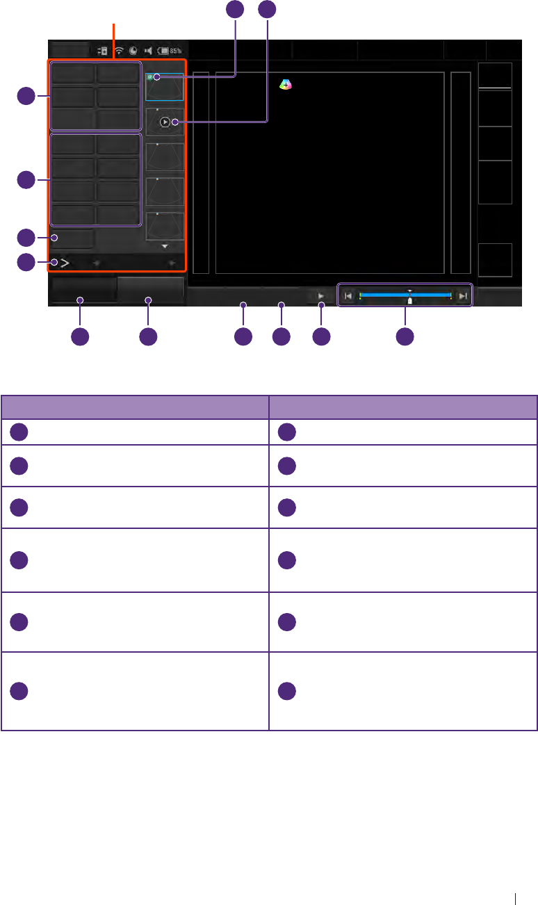
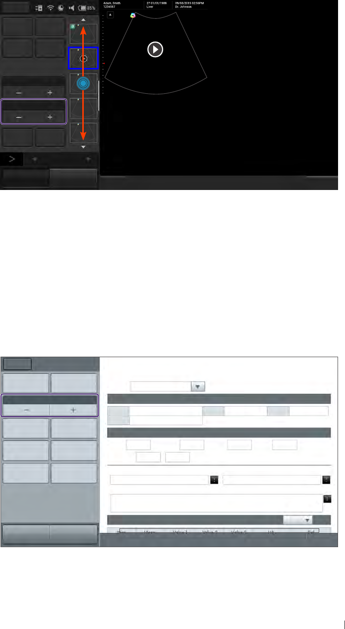
Imaging screen (Frozen)
During an exam, touch Freeze to review all the ultrasound images
stored in the cine buffer frame by frame, or play back these frames in
a continuous loop. The operator can also measure, calculate and add
annotations to the frozen images or clips.
Menu Adam, Smith
1234567
27 01/01/1988
Liver
09/03/2015 02:56PM
Dr. Johnson
Medical
Center
Distance Ellipse TI
MI
Probe
Trace Calc
Measure Del
Annot Label
Arrow Annot Del
BDMK Probe Pos
Rotate Erase BDMK
Print
12
B Function
Freeze Save Image Fun.Key Set Start Set End
1 490
End Exam
Control panel
10
4
6
7
8
9
3
5
12
1
2
11
Figure 7 Frozen imaging screen (example)
No. Function No. Function
1
This image is added to a report.
2
Cine clip
3
The progress bar
4
Play back the recent image
frame sequence.
5
Set the end point of the cine clip.
6
Set the start point of the cine
clip.
7
Save Image button
Save a frozen image or a clip to
the system hard drive.
8
Freeze button (Enabled)
Touch this button again to return
to the real-time scan.
9
Open the next page of the image
control settings. (See page 56)
10
Print out the image from the
thermal printer connected to the
system via the USB connector.
11
Add annotations, including
arrows, texts and body marks,
to the current image using the
virtual keyboard .
12
Perform measurements and
calculations on the current
image.
55
Basic operations Identify the main screen layout
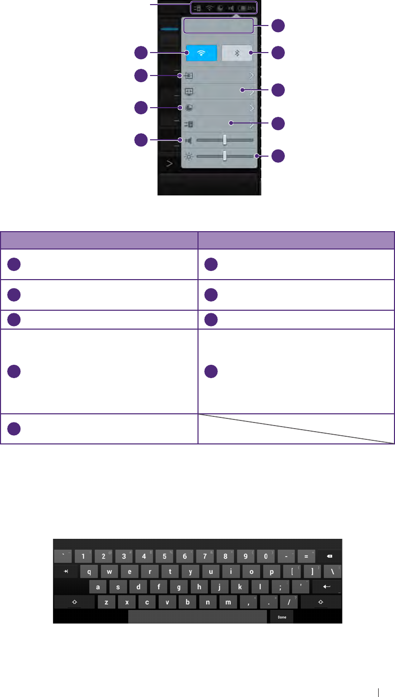
System tools
Touch anywhere on the system toolbar to open the system tools widget.
Touch an item to adjust its setting.
Menu
B14:56 2015. 08. 07
Tuesday
M
LAN on
Cast display off
Used 85%
Connecting
Freeze Save Image
1
2
4
6
7
8
9
3
5
System
toolbar
Figure 8 System tool widget
No. Function No. Function
1
Manually set current date and
time.
2
Enable/Disable the Bluetooth
function.
3
Cast the system screen to an
external display.
4
Check and manage outgoing
queues.
5
Adjust the brightness.
6
Adjust the volume.
7
Display the percentage of the
system storage used. Follow
the pop-up message to free up
storage space by deleting exams
done in the appointed number of
weeks.
8
Manage the Ethernet settings
9
Enable/Disable the WLAN
function.
Virtual keyboard
Whenever the operator needs to enter text in a text field, simply touch
the field, and a virtual keyboard appears on the lower part of the screen.
Touch a letter to enter text; when finishing inputs, touch Done.
Figure 9 Virtual keyboard
56
Basic operations Identify the main screen layout
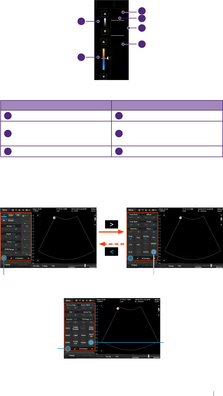
Scan properties display
The imaging window includes a text display information about the current
scan.
Medical
Center
TI 0.27
MI 1.04
CLA
0Gn 58
15.0cm 4FPS
1/ 1
M/ 80.0
Gn 45
M/ 80.0
1.0
20.0
1/ 3
15
-15
1
2
4
6
3
5
Figure 10 Scan properties display (example)
No. Function No. Function
1
Thermal index/Mechanical index
2
Transducer type
3
2D image control settings:
Gain/Depth/FPS/QBeam/PWR
4
Color image control settings:
Gain/PWR/PRF/Wall Filter/
Persistence
5
Color wedge
6
Grayscale wedge
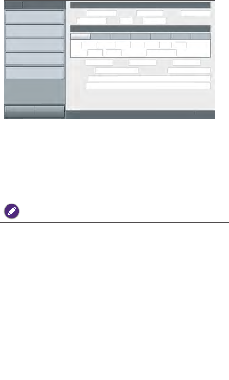
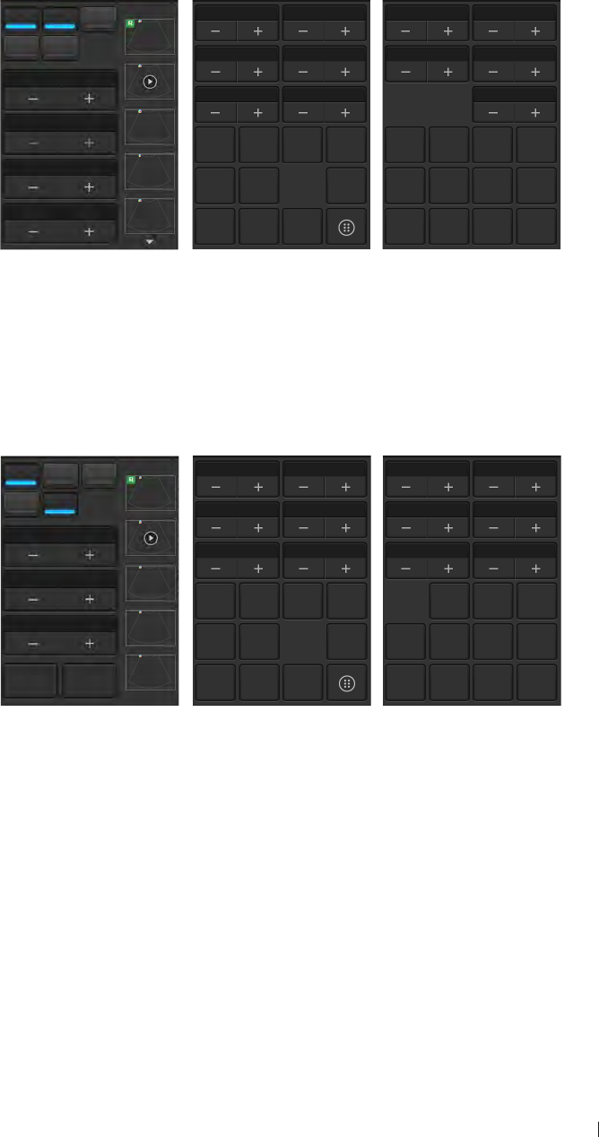
Switch the control panel pages
The functions available on the control panel vary, depending on the scan
mode and the transducer connected.
Touch to display more functions
(page 3).
Page 3
Touch to return to
the first page (page 1).
Touch to return to
the previous page
(page 2).
Touch to open the next page
(page 2).
Page 1 Page 2
57
Basic operations Add a new patient
Add a new patient
The system allows skipping entering patient information if the operator
needs to start the ultrasound exam immediately. However, the images
and cine loops cannot be saved. We recommend that the operator
defines the patient within the system before scanning to avoid mix-ups
and to generate reports.
1. On the imaging screen, touch Menu > Patient.
Menu Patient Patient Information
Edit Patient First name Middle Name Last Name
ID Gender DOB Age:
New Patient Exam History
Cardiology GY OB Abdomen Small Part Urology Vascular
Pause Exam Height cm Weight kg BSA: m2HR bpm
Blood Press /mmHg RA Press mmHg
Current Exam History
Accession Institution Operator
Save Referring physician Interpreting Physician
Description
Comment
Scan Previous End Exam
Figure 11 Patient screen
2. Touch New Patient. Enter the patient information as much detail as
possible:
» Touch in a text entry field, and use the virtual keyboard below to
input contents.
» Touch Next on the keyboard to go to the next field.
» Touch Done on the keyboard.
To create a valid patient profile, at least the patient’s First name
and ID number should be filled in.
3. Touch Save.
To start scanning the patient, touch Scan.
To update patient information
1. On the patient screen, touch Edit Patient.
2. Enter the new information in the appropriate fields.
58
Basic operations Load a work list
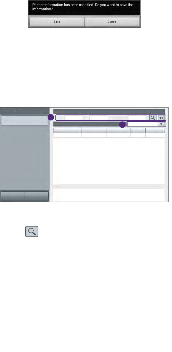
3. Touch anywhere on the screen, the following system message
appears. Touch Save to save changes.
Load a work list
The system conforms with the Digital Imaging and Communications
in Medicine (DICOM) standard, which is the industrial standard for the
communication and management of patient data between devices in the
hospital. The operator can load patient information in a work list via the
DICOM server.
1. On the imaging screen, touch Menu > Work list.
Menu Worklist Query Worklist
Start exam Name ID 234567|Accession#
Worklist: 1 2015.08.29 All
Name ID Accession# Gender DOB
Keane Fox 234567 123456 M 19991109
Details
Scan Previous
2
3
Figure 12 Work list screen
2. Enter the query criteria in any of the Name/ID/Accession# fields,
and touch to start the query. Patients matching the query will be
listed on the screen.
3. Select the number of patients to scan on the worklist from the drop-
down menu.
To start scanning, select a patient, and then touch Start exam.
59
Basic operations Select a preset
Select a preset
The system provides predefined presets for all supported transducers.
Choosing an exam loads optimized presets for image control settings,
based on the anatomy to be scanned, the transducer used, and the
scanning mode. The presets also specify the measurements appropriate
for the exams. The operator can directly use the optimized presets, or
adjust any of the image control settings as necessary for the specific
patient and the specific exam.
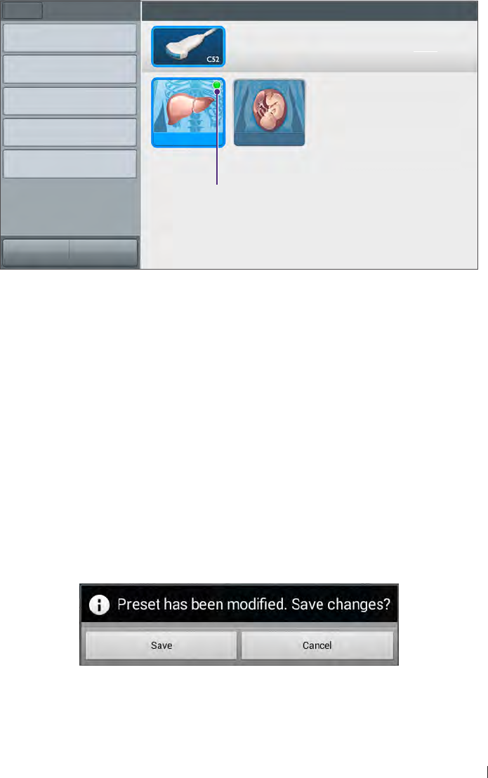
1. On the imaging screen, touch Menu > Preset. All the available
presets compatible with the connected transducer displays on the
preset screen.
Menu Preset Select Preset
Save current used preset as
Management
Export
Import Liver Obstetric
Preset Setup
Currently used preset
Scan Previous
Figure 13 Preset screen
2. Touch the exam/preset to scan, and the operator will be redirected
automatically to the real-time imaging screen.
To modify current presets
1. On the preset screen, touch Movement.
2. Touch Move, and drag to re-arrange the order of the presets. To hide
an unwanted preset, touch Hide & Show Preset, and touch Off on
the preset.
3. Touch anywhere on the screen, the following system message
appears. Touch Save to save changes.
60
Basic operations Set the transducer orientation
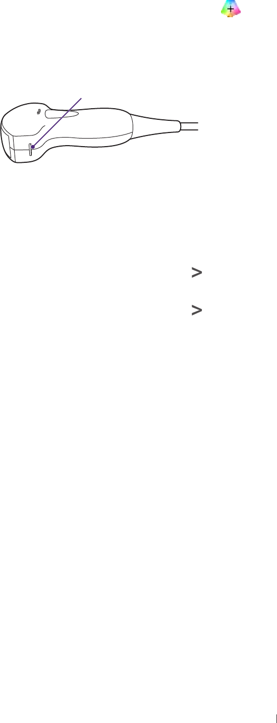
Set the transducer orientation
Upon entering all imaging modes, the orientation marker ( ) displays
at the default location (usually at the top left side of the image), and
suggests the operator the direction of holding the transducer. The
orientation marker on the screen corresponds to the position of the
orientation marking on the side of the transducer.
Orientation marker
Figure 14 Transducer orientation (Example transducer-C52A)
The operator can change the left/right orientation of the image (real-
time or frozen) in various imaging (single or dual) without rotating the
transducer head itself.
To reverse left and right
On the imaging screen (real-time or frozen), touch > L/R.
To reverse up and down
On the imaging screen (real-time or frozen), touch > U/D.
Adjust the displayed image
On the real-time imaging screen, touch the corresponding mode
selection button to select a scan mode. Use the image control settings to
further optimize the image. For explanations and usage of these settings
on specific modes, please refer to their respective chapters.
The operator can also perform the following operations to adjust the
contents of the imaging window.

61
Basic operations Adjust the displayed image
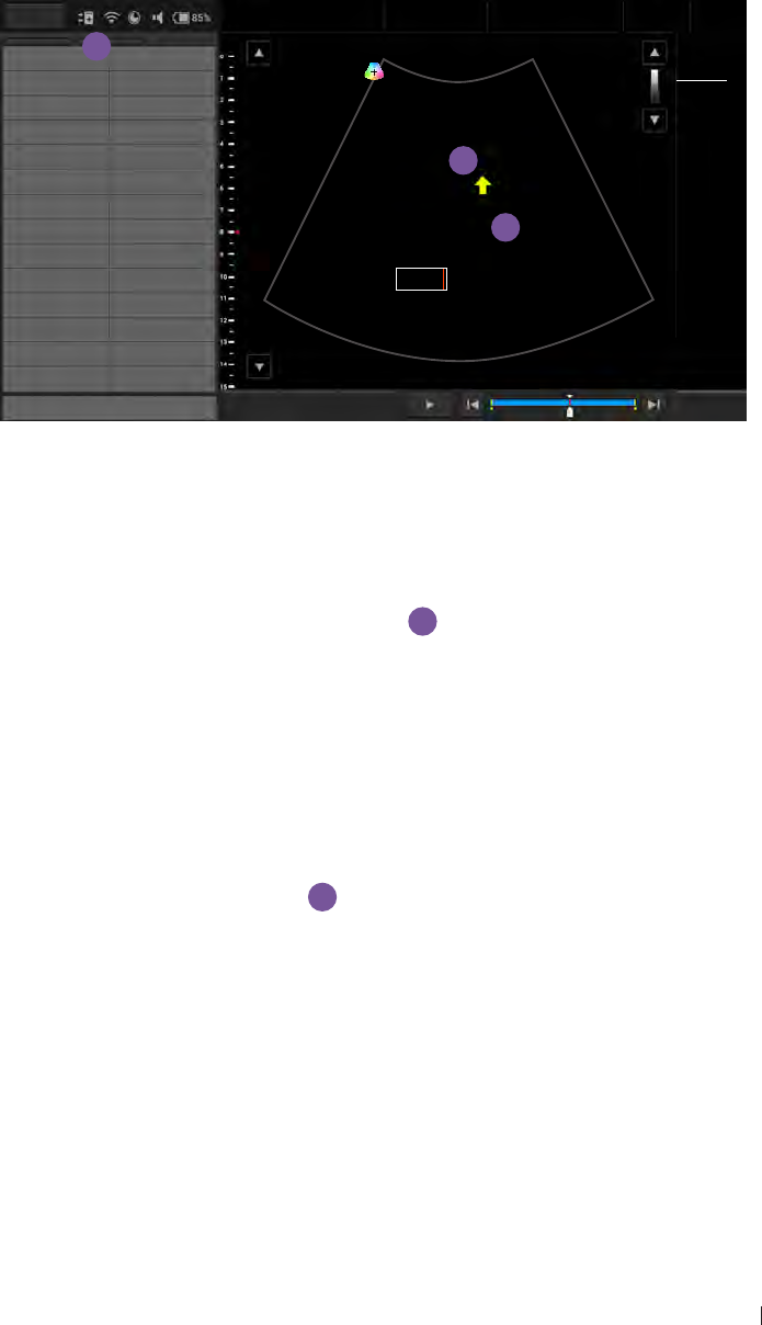
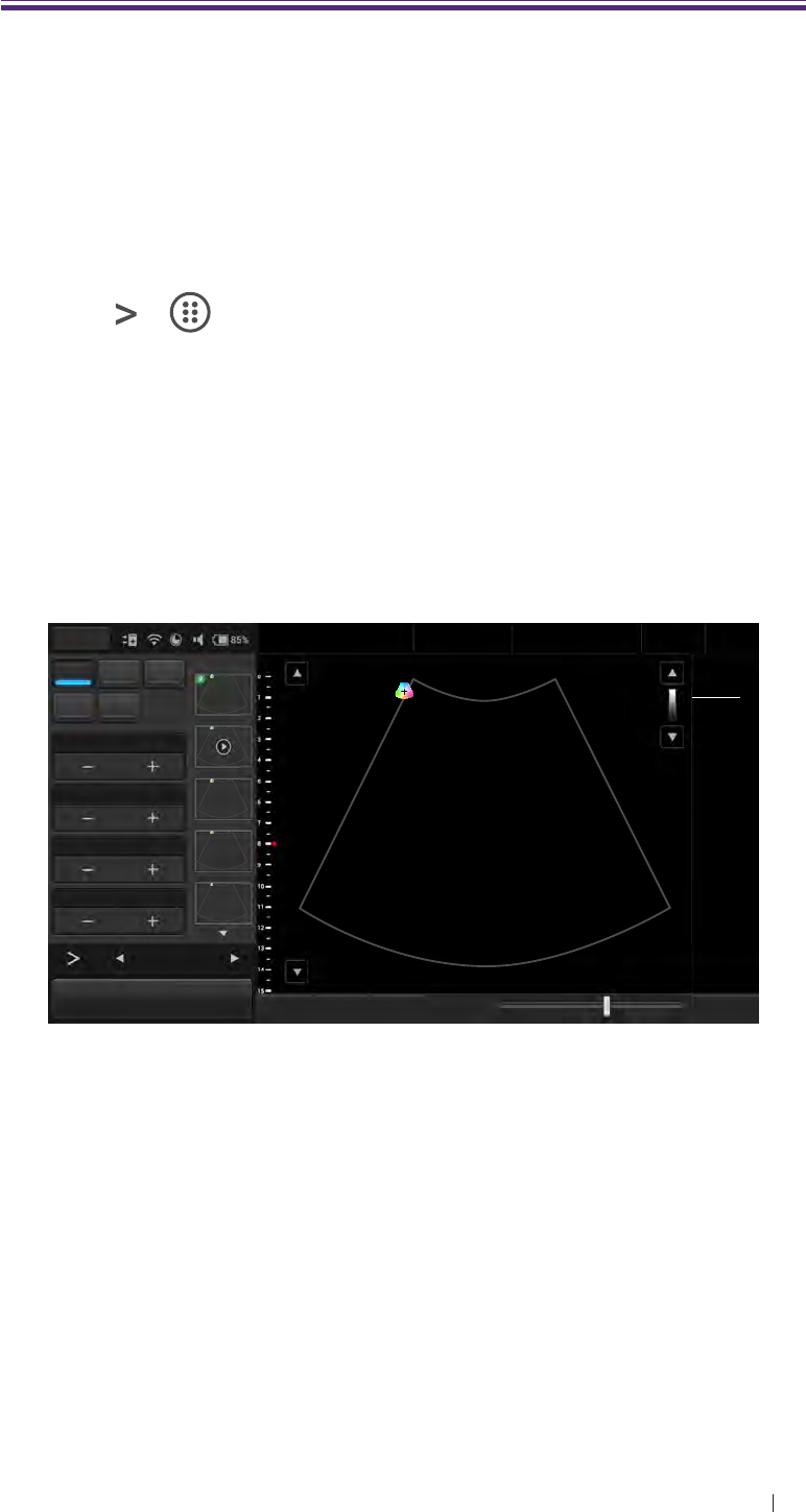
Enlarge an area of the image
To further examine the anatomy by enlarging a region of the image (real-
time or frozen), use the zoom function.
1. On the imaging screen, touch > > Zoom. The ROI (Region of
Interest) box appears on the center of the image.
Menu Adam, Smith
1234567
27 01/01/1988
Liver
09/03/2015 02:56PM
Dr. Johnson
Medical
Center
Chroma Map 0Sector Width 26 TI 0.11
MI 0.92
CLA
0Gn 58
15.0cm 15FPS
1/ 1
M/ 80.0
60/ 0
0/ 4
GSC 0Sector Pos ROI box
Acoustic 1540 TX Power 80.0
Zoom Image
Reverse Needle Erase
BDMK
Annot Label Arrow Annot
Del
BDMK Probe
Pos Rotate Close
Zoom View: 1.0x
B Function
Freeze Save Image Fun.Key Tuning TGC Penetration Resolution End Exam
Figure 15 Enlarge a ROI (normal image)
Touch and drag inside of the ROI box to move it to the area to
enlarge. Touch on any of the box’s four corners and drag to resize
the ROI box.
2. Touch anywhere outside the ROI box to enlarge selected area.
Menu Adam, Smith
1234567
27 01/01/1988
Liver
09/03/2015 02:56PM
Dr. Johnson
Medical
Center
Chroma Map 0Sector Width 26 TI 0.11
MI 0.92
CLA
0 Gn 58
15.0cm 15FPS
1/ 1
M/ 80.0
60/ 0
0/ 4
GSC 0Sector Pos
Acoustic 1540 TX Power 80.0
Zoom Image
Reverse Needle Erase
BDMK
Annot Label Arrow Annot
Del
BDMK Probe
Pos Rotate Close
Zoom View: 2.0x
B Function
Freeze Save Image Fun.Key Tuning TGC Penetration Resolution End Exam
Figure 16 Enlarge a ROI (zoomed image)
The operator can still move the enlarged area by touching and
dragging anywhere on the image.
62
Basic operations Freeze an image
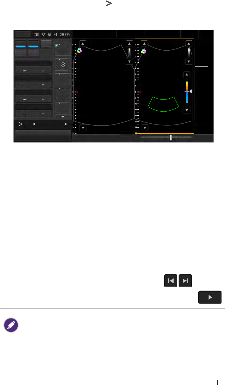
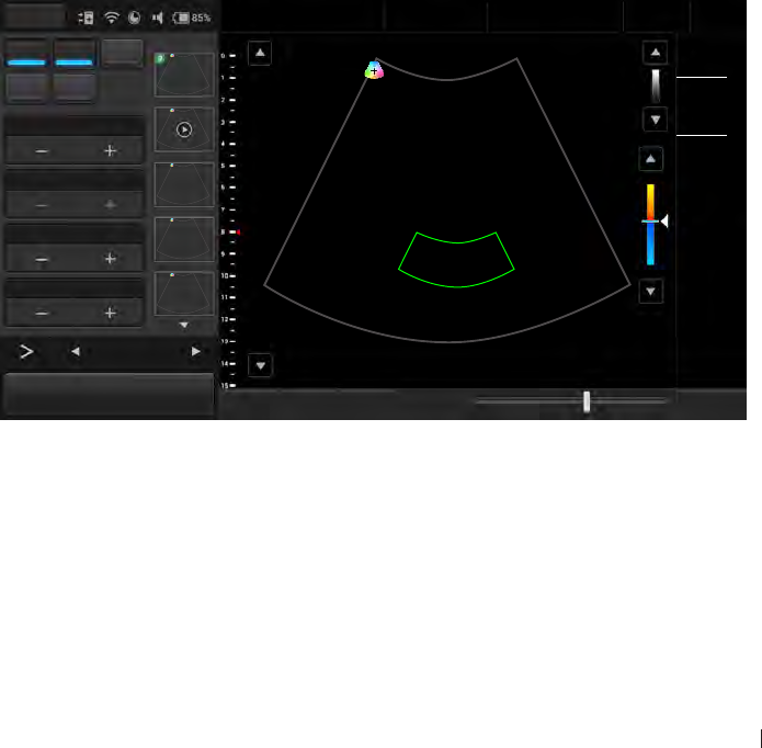
Split the imaging screen
The system allows splitting the imaging screen into two sections to view
two current scans for a patient. The operator can acquire one scan for
the patient, enable split screen, and then acquire another scan from a
different angle, location or with a different scan mode.
On the imaging screen, touch > Dual. The ultrasound software
immediately freezes the current scan, and copies the current settings for
the image to the second screen.
Menu Adam, Smith
1234567
27 01/01/1988
Liver
09/03/2015 02:56PM
Dr. Smith
Medical
Center
B Color PW TI 0.27
MI 1.04
CLA
M Power 0 0 Gn 58
15.0cm 4FPS
1/ 1
M/ 80.0
Color Gain 45
Gn 45
M/ 80.0
1.0
20.0
1/ 3
PRF 1.0 15
Steering 0
-15
WF 20.0
12
Color Function
Freeze Save Image Fun.Key Tuning TGC Penetration Resolution End Exam
Figure 17 Dual screen
To select a screen, touch Toggle. Only one screen can be active at a
time. The operator can then apply any image control settings and use
scan modes independently to either screen. For example, the operator
can acquire a 2D scan, activate dual screen, and then acquire a Color
Doppler scan in the second screen.
To leave the dual screen, touch Dual again.
Freeze an image
During a real-time scan, touch Freeze to freeze live ultrasound images
recorded by frame and stored temporarily in the cine buffer. Depending
on the mode selected, a certain number of frames are recorded.
To view the saved images frame by frame, touch / .
To play back saved images in a continuous cine loop, touch .
To re-start a new live scan, touch Freeze again.
If no frozen image or cine loop are saved, restart live scanning
erases the frame data. Make sure any needed images are saved
or printed before acquiring new scan data.
63
Basic operations Add annotations and measurements
Add annotations and measurements
On the frozen imaging screen, the operator can add annotations and
measurements to the ultrasound images in order to explain the anatomy.
If you return to the real-time imaging screen without saving the image, all
the annotations and measurements added will be cleared.
Annotations
b
a
c
Menu Adam, Smith
1234567
27 01/01/1988
Liver
09/03/2015 02:56PM
Dr. Johnson
Medical
Center
TI 0.11
MI 0.92
CLA
Left Right
Upper Lower 0Gn 58
15.0cm 15FPS
1/ 1
M/ 80.0
60/ 0
0/ 4
Medial Lateral
Anterior Posterior
SAG TRANS
PROX MID
LT Kidney RT Kidney Tumor
LT Lobe RT Lobe
Aorta Liver
CBD IVC Lower
Duodenum Fluid
Appendix Pancreas
Gallbladder Spleen
Caudate Bowel
Delete Set Home Go home
1 490
End Exam
Close
Figure 18 Add annotations
Arrow
Touch Arrow. An arrow appears at the text home position. Drag the
arrow to place it to the desired location
a
.
Text
1. Touch Annot. A virtual keyboard and a text cursor (I-beam) appear at
the text home position.
2. Type the texts directly. Touch Done on the keyboard to finish inputs.
3. Drag the text cursor to where you want the new texts to be, and
release it to place the texts
b
.
Set the text home position
The operator can choose a specified position in the image display as the
starting location, which is the text home position.
1. Touch Annot.
2. Drag the text cursor to the desired text home position.
3. Touch Set Home.
64
Basic operations Add annotations and measurements
Label
1. Touch Label. A predefined text menu and a text cursor (I-beam)
appears at the text home position
c
.
2. Select a text label to place it at the current cursor position, and touch
Close.
3. Drag the cursor/label to where you want the texts to be.
The text labels are still editable. Touch the label to display the virtual
keyboard, and start editing the texts. Touch Done on the keyboard to
finish editing.
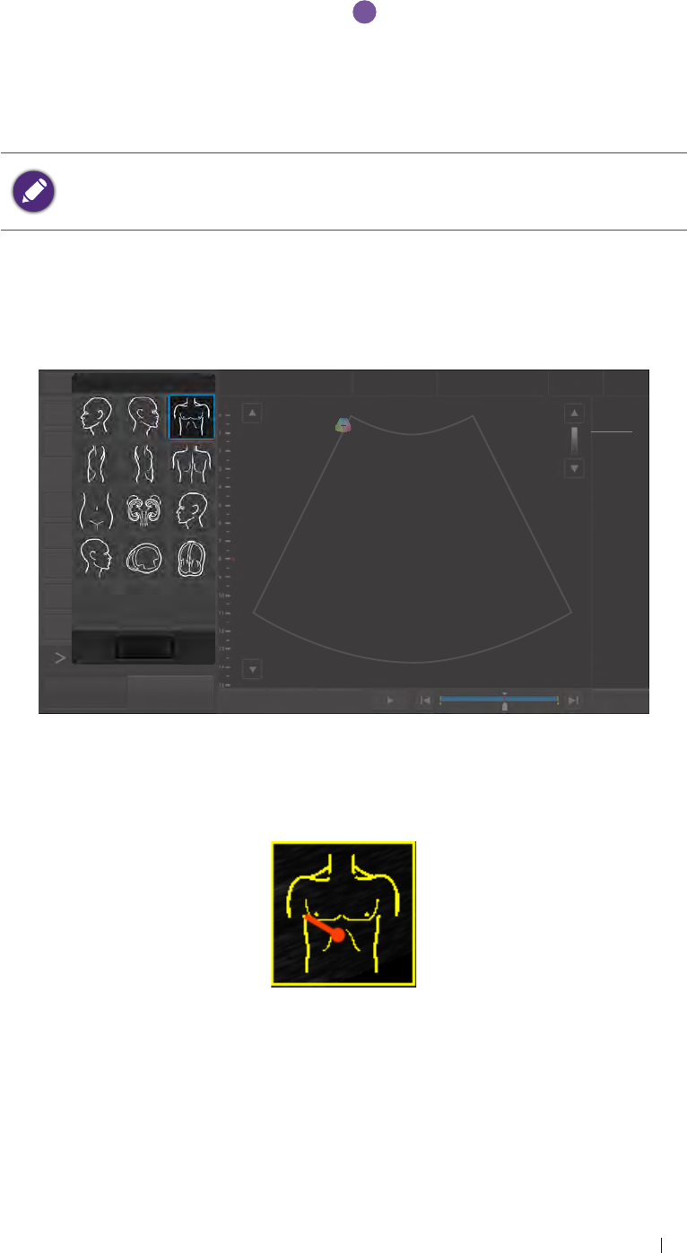
BDMK
1. Touch BDMK to display the body marker menu.
Menu Adam, Smith
1234567
27 01/01/1988
Liver
09/03/2015 02:56PM
Dr. Johnson
Medical
Center
Distance TI 0.11
MI 0.92
CLA
Trace 0Gn 58
15.0cm 15FPS
1/ 1
M/ 80.0
60/ 0
0/ 4
Annot
Arrow
BDMK
Rotate
Print
Freeze Save Image Fun.Key Set Start Set End
1 490
End Exam
Body Mark (12)
Close
Figure 19 Add a body mark
2. Select a body mark. A pictogram of the body mark with a transducer
indicator displays on the image.
Figure 20 Pictogram of the body mark (example)
3. Touch Probe Pos, Touch anywhere on the image and move to place
the body marker to the desired location on the body mark.
4. Touch Rotate. Touch anywhere on the image and move to rotate the
transducer indicator.
65
Basic operations Add annotations and measurements
5. Touch and hold the pictogram, and drag to move it to the desired
location on the image.
To delete annotations added, including texts and arrows, touch
Annot Del to delete the last added annotations.
To delete the body mark added, touch Erase BDMK.
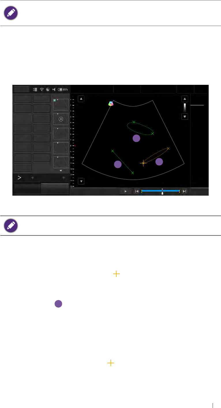
Measurements
Measurements accompanying ultrasound images supplement other
clinical procedures available to the attending physician. The operator
can perform as many measurements as needed.
a
c
b
Menu Adam, Smith
1234567
27 01/01/1988
Liver
09/03/2015 02:56PM
Dr. Johnson
Medical
Center
Distance Ellipse TI 0.11
MI 0.92
CLA
1 D 66.7 mm
2 TA 2641.5 mm2
TB 0.5 mm
3 EA 119.8 mm2
EP 122.6 mm
Ea 61.2 mm
Eb 2.5 mm
Trace Calc 0Gn 58
15.0cm 15FPS
1/ 1
M/ 80.0
60/ 0
0/ 4
Measure Del
Annot Label 2
Arrow Annot Del
BDMK Probe Pos
Rotate Erase BDMK
Print
51
B Function
Freeze Save Image Fun.Key Set Start Set End
1 490
End Exam
Figure 21 Perform measurements
To delete measurements added, touch Measure Del to delete the last
added measurements.
Distance
Used to measure a distance.
1. Touch Distance. A “cross” cursor appears on the image. Move the
target cursor to where you want to start measuring and release it.
2. Drag the target cursor to where you want to finish measuring, and
then release it
a
.
The measured results (values) appear on the top left corner of the
ultrasound image.
Trace
Used to trace an irregular shape.
1. Touch Trace. A “cross” cursor appears on the image. Move the
cursor to where you want to start measuring and release it.

66
Basic operations Save and print the image
2. Drag the cursor along the outline of the object to trace.
Figure 22 Trace an outline
3. When the tracing is nearly done, release your finger and the system
completes the loop by drawing a line from the current cursor position
to the starting point
b
.
The measured results (values) appear on the top left corner of the
ultrasound image.
Ellipse
Used to measure a circumference.
1. Touch Ellipse. A “cross” cursor appears on the image. Move the
target cursor to one end of the area you want to measure and release
it to set the start point of measurement.
2. Drag the target cursor to the other end of the desired area, and
release it to set the end point of measurement. An oval area is then
measured
c
.
The measured results (values) appear on the top left corner of the
ultrasound image.
Save and print the image
After adding needed annotations/measurements to the image, the
operator can save or print the image.
Save an image
On the frozen imaging screen, touch Save Image to save the current
frame as an image. The saved image will be displayed in the thumbnail
list.
Save a cine clip
To save the frames as a cine clip, touch and hold Save Image.
Print an image
To print out the image, touch Print.
67
Basic operations Review the image
Review the image
On the frozen screen, scroll up and down on the thumbnail list to view
the thumbnails of all the saved images/clips. To further examine one or a
set of images/clips, touch the thumbnail(s) of the needed image or cine
clip to display the review screen.
Menu Adam, Smith
1234567
27 01/01/1988
Liver
07/08/2015 02:56PM
Dr. Johnson
Medical
Center
Add to Report Gen Report
TI 0.11
MI 0.92
CLA
1Gn 60
9.0cm 28FPS
0/ 1
M/ 80.0
3/ 1
0/ 4
Export study Delete
Multi-Select 1*1
Multi-Image 1*1
Print Study List
3/12
B Function
Freeze Save Image Fun.Key Set Start Set End End Exam
Figure 23 Review the image
Perform multiple selections
The operator can perform actions to more than one image/clip at a time.
Menu
Add to
Report Gen Report
Export study Delete
Multi-Select 3*3
Multi-Image 1*1
Print Study List
12
B Function
Freeze Save Image Fun.Key Select All Deselect All End Exam
Figure 24 Perform multiple selections
1. Touch the + button under Multi-Select. Scroll up and down on the
thumbnail window and touch to select up to 9 images/clips.
To quickly select all images, touch Select All.
To cancel all selections, touch Deselect All.
68
Basic operations Review the image
2. Touch an action button. For example, touch Delete to delete all
selected images/clips.
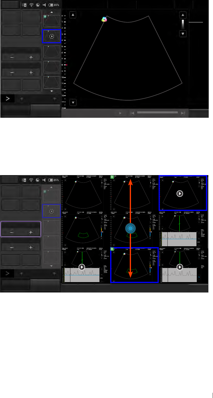
Compare images
To compare the scanned images/clips, touch the + button under Multi-
Image.
Menu
Add to
Report Gen Report
Export study Delete Please touch thumbnail to add to review list.
Multi-Select 1*1
Multi-Image 2*2
Print Study List
12
Please touch thumbnail to add to review list. Please touch thumbnail to add to review list.
B Function
Freeze Save Image Fun.Key End Exam
Figure 25 Compare images
Scroll up and down the thumbnail list, and touch to select up to 4
images/clips to display for comparison.
Generate a report
1. On the review screen, touch the thumbnails of the desired images
and touch Add to Report.
2. Touch Gen Report to display the following screen.
Menu Report Signature: / Study date: 2015/09/03 / Exam type: Cardiology
Institution: / Referring: / Interpreting:
Print Print Preview Template template_1
Patient information
Image Layout 1 column
Name DOB Age
ID
Add Image Rem Image Study Specific Information
Exam History Export
Height cm Weight kg BSA: m2HR bpm
Blood Press /mmHg RA Press mmHg
Save as Save Prompts Findings
Comments
Ultrasound Image
Scan Previous
End Exam
Figure 26 Report screen

69
Basic operations Export the exam
3. Fill in information about the patient and the study, if not complete, and
add comments using the virtual keyboard.
4. Scroll down to review the images added, and add comments to
individual images, if needed.
The operator can still add/remove images to/from the report without
going back to the review screen. Touch Add Image/Rem Image to
display the image editing screen. Check the desired images and
touch Add to Report or Remove from report.
5. Touch the + button under Image Layout to select the numbers of
columns for placing the images on a report.
6. Touch Print Preview to preview the report.
7. To print out the report, touch Print; to save the report, touch Save as,
select the file format and directory, and then touch Save.
Export the exam
The operator can export exams and images to an external storage or the
DICOM server. When exporting an exam, an image or a cine loop, the
system creates a uniquely named subdirectory for each exam, image or
loop.
The system provides three ways of exporting the exam:
On the review screen, touch Export study > Export to DICOM or
Export to external storage.
On the exam history screen, check the completed exams, and touch
Export Exam > Export to DICOM or Export to external storage.
On the report screen, touch Export > Export to DICOM or Export to
external storage.
To set the default export directory, exporting to DICOM automatically
after ending the exam and more, please go to Menu > Setting.
End the exam
An exam is not complete if the operator proceeds with a new exam
without ending the previous one.
To end the exam, touch End exam on the imaging screen.
To check the exam status, please go to Menu > Exam history.
70
Scan modes overview B mode overview
5 Scan modes overview
All of the information in this chapter pertains to real-time imaging. Many
of the controls and functions change when the operator freeze the scan.
For information on using functions when the scan is frozen, please refer
to “Annotations” and “Measurements”.
On the real-time imaging window:
Touch the mode selection buttons to select a scan mode (See
“Imaging screen (Real-time)”).
Touch > to switch the control panel pages to go through the
available functions (See “Switch the control panel pages”).
B mode overview
The system delivers 2-dimensional digital imaging using 256 digital
beam-forming channels. This imaging mode delivers excellent
image uniformity, tissue contrast resolution, and steering flexibility in
frequencies from 2 MHz to 15 MHz.
Menu Adam, Smith
1234567
27 01/01/1988
Liver
09/03/2015 02:56PM
Dr. Smith
Medical
Center
BColor PW TI 0.11
MI 0.92
CLA
M Power 0Gn 58
15.0cm 15FPS
1/ 1
M/ 80.0
60/ 0
0/ 4
B Gain 58
Depth 15.0
Focus 8.0
DYN Range 60
12
B Function
Freeze Save Image Fun.Key Tuning TGC Penetration Resolution End Exam
Figure 27 B mode real-time scan

71
Scan modes overview B mode overview
B mode image controls
Use the following 2D image controls during live scanning.
BColor PW
M Power
B Gain 58
Depth 15.0
Focus 8.0
DYN Range 60
12
Focal Zone 1QScan 1
Focal Span 1Persist 4
Steering 0Reject 4
Freq
MTrap Density
HTHI
L/R U/D QRange
0
QBeam
1
Dual Toggle Full Scr
Chroma Map 0Sector Width 256
GSC 0Sector Pos
Acoustic 1540 TX Power 80.0
Zoom Image
Reverse Needle Erase
BDMK
Annot Label Arrow Annot Del
BDMK Probe Pos Rotate Close
Figure 28 B mode image controls
Gain: adjust amplification of the returning echoes, which adjust the
amount of echo information displayed in an image.
Scan depth: adjust the field of view.
Focus depth: increase the resolution for a specific area.
Dynamic range: control the range of acoustic levels displayed in the
image, which affect the contrast of the image.
Focal zones: select the focal number which also affect the acoustic
power indices.
Focal span: adjust the distance between the focal zones.
QScan: allow scanning from different angles, which helps reinforce
the real structures of an ultrasound image by eliminating artifacts,
such as speckle, noise or refractive shadows.
Persistence: adjust the amount of averaging (real-time) images.
Reject: adjust the display priority of the 2D grayscale pixels.
Frequency: change the scan frequency. As frequency increases, the
resolution becomes higher while the penetration becomes lower.
Trapezoidal imaging: increase the range of view of the ultrasound
image.
Chroma map: adjust the chroma (color tone and saturation) value
with different brightness.
Gray scale curve (GSC): change how the amplitude is converted to
brightness.
Acoustic: set the minimum acoustic output power value while still
sufficient for diagnostically acceptable information.
QBeam: permit electronic steering of the ultrasound beam to acquire
scans of an ROI from several directions.
72
Scan modes overview Color/Power Doppler mode overview
Sector width and position: adjust the imaging area of both the sector
and the transducer to the ROI. A smaller sector width increases the
frame rate.
Image reverse: reverse the image orientation horizontally and
vertically.
Color/Power Doppler mode overview
Color Doppler mode is used to detect the presence, direction, and
relative velocity of blood flow by assigning color-coded information to
these parameters. The color is depicted in a region of interest (ROI) that
is overlaid on the 2D image. Non-inverted flow towards the transducer
is assigned shades of red, and flow away from the transducer displays
in shades of blue. The mean Doppler shift is then displayed against a
grayscale scan of the structures.
All forms of ultrasound-based imaging of red blood cells are derived from
the received echo of the transmitted signal. The primary characteristics
of this echo signal are its frequency and its amplitude (or power). The
frequency shift is determined by the movement of the red blood cells
relative to the transducer – flow towards the transducer produces a
higher-frequency signal than flow away from the transducer. Amplitude
depends on the amount of moving blood within the volume sampled
by the ultrasound beam. The operator can also apply a high frame rate
or high resolution to control the quality of the scan. Higher frequencies
generated by rapid flow are displayed in lighter colors, and lower
frequencies in darker colors.
Menu Adam, Smith
1234567
27 01/01/1988
Liver
09/03/2015 02:56PM
Dr. Smith
Medical
Center
B Color PW TI 0.27
MI 1.04
CLA
M Power 0Gn 58
15.0cm 4FPS
1/ 1
M/ 80.0
Color Gain 45
Gn 45
M/ 80.0
1.0
20.0
1/ 3
PRF 1.0 15
Steering 0
-15
WF 20.0
12
Color Function
Freeze Save Image Fun.Key Tuning TGC Penetration Resolution End Exam
Figure 29 Color Doppler mode real-time scan
In Power Doppler Mode, low flow rate in small vessels are clearly
observed. Colors are carried out only to demonstrate the blood flow, but
contain no velocity information, thus, offers no directional information.
73
Scan modes overview Color/Power Doppler mode overview
Both Color and Power Doppler modes can work with other scan modes
to form duplex and triplex modes.
Color/Power Doppler mode image controls
Use the following Color/Power Doppler mode image controls during live
scanning.
B Color PW
M Power
Color Gain 45
PRF 1.0
Steering 0
WF 20.0
12
Depth 15.0 QScan 1
Focus 8.0 Persist 3
Baseline 15 Reject 255
Freq
M
Flow
Invert
Density
HTHI
L/R U/D QBeam
1
Dual Toggle Full Scr
Color Map 1Sector Width 256
Threshold 4Sector Pos
TX Power 80.0
Zoom Image
Reverse Needle Erase
BDMK
Annot Label Arrow Annot
Del
BDMK Probe
Pos Rotate Close
Figure 30 Color Doppler mode image controls
Pulse Repetition Frequency (PRF): adjust the velocity range of the
display, which manifests as a scale.
Wall filter (WF): adjust the wall filter setting to reduce or eliminate
unwanted low-frequency, high-intensity signals generated by
movements of blood vessel walls.
BColor PW
MPower
Power Gain 50
PRF 0.8
WF 16.0
Dir Power Flow Invert
12
Depth 15.0 QScan 1
Focus 8.0 Persist 3
Steering 0 Reject 255
Freq
MZoom Density
HTHI
L/R U/D QBeam
1
Dual Toggle Full Scr
Color Map 1Sector Width 256
Threshold 4Sector Pos
Baseline 15 TX Power 80.0
Image
Reverse Needle Erase
BDMK
Annot Label Arrow Annot
Del
BDMK Probe
Pos Rotate Close
Figure 31 Power Doppler mode image controls
Dir Power: activate Directional DPI with the DPI indicator displaying
the direction of flow for use in applications where sensitivity and
directional information are both required.
74
Scan modes overview M mode overview
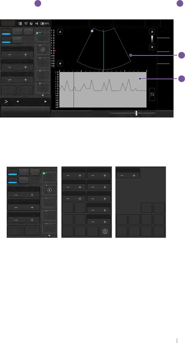
M mode overview
M mode imaging is used simultaneously with 2-dimensional (B
mode) imaging, to determine patterns of motion for objects within the
ultrasound beam. M mode displays scan data of the anatomy in the 2D
Imaging window
a
, and the motion scan in the Time Series window
b
.
Typically, this mode is used for viewing motion patterns of the heart.
b
a
Menu Adam, Smith
1234567
27 01/01/1988
Liver
09/03/2015 02:56PM
Dr. Johnson
Medical
Center
TI 0.14
MI 0.95
CLA
BColor PW
MPower 0Gn 58
15.0cm 13FPS
1/1
M/ 80.0
M Gain 50
Steer M 0
Gn 50
M/ 80.0
PEK
M Process PEK
Speed
1/2x Video Invert
12
M Function
Freeze Save Image Fun.Key Tuning M Update Penetration Resolution End Exam
Figure 32 M mode real-time scan
M mode image controls
Use the following M mode image controls during live scanning.
BColor PW
MPower
M Gain 50
Steer M 0
M Process PEK
Speed
1/2x Video Invert
12
Depth 15.0 DYN Range 1
Focus 8.0 Display V 1/2
Steering 0 Reject 4
Freq
MZoom TX Power 80.0
L/R U/D Line Pos 128
Dual Toggle Full Scr
Chroma Map 0
ECG Erase
BDMK
Annot Label Arrow Annot
Del
BDMK Probe
Pos Rotate Close
Figure 33 M mode image controls
M process: select the method for detection processing the M trace
display.
Steer M: adjust the M mode cursor line (M-line) position.
Sweep speed: adjust how fast the timeline is scanned across the
Time Series window.
Video invert: invert the M trace display in relation to brightness.
Scan lined position: adjust the scan line position.
75
Scan modes overview Pulsed-Wave (PW) Doppler mode overview
Display format: adjust the layout of the B+M mode ultrasound image.
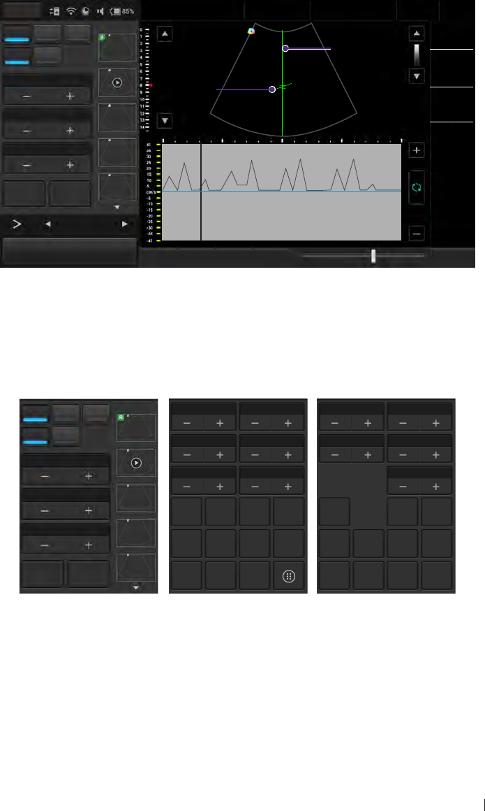
Pulsed-Wave (PW) Doppler mode overview
A pulsed-wave Doppler scan produces a series of pulses used to study
the motion of blood flow selectively in a small region along a desired
ultrasound cursor, called the Doppler Range Gate (RG) located on the
spectral Doppler cursor. A short line across the sample volume is called
the Flow Direction cursor. This cursor line should be aligned to the blood
flow direction when measuring the flow velocity.
Menu Adam, Smith
1234567
27 01/01/1988
Liver
09/03/2015 02:56PM
Dr. Johnson
Medical
Center
TI 0.28
MI 0.4
CLA
BColor PW
Spectral Doppler Cursor
M Power 0Gn 58
15.0cm 7FPS
1/1
M/ 80.0
PW Gain 50
Flow direction cursor
PRF 2.0
Gn 50
M/ 80.0
2.0
40.0
60 degree
8.08 cm
2.49 mm
Angle 60
Angle±60 2D Refresh
12 Update
PW Function
Freeze Save Image Fun.Key Tuning TGC PW Update Penetration Resolution End Exam
Figure 34 PW Doppler mode real-time scan
PW Doppler mode image controls
Use the following PW mode image controls during live scanning.
BColor PW
M Power
PW Gain 50
PRF 20
Angle 60
Angle±60 2D Refresh
12
Baseline 8DYN Range 4
WF 40.0 SV Size 2.49
Steering -20 Reject 4
Freq
M
Flow
Invert
Video
Invert
Output
cm/s
L/R U/D Speed
1.2x Sound
Dual Toggle Full Scr
Chroma Map 0Line Pos 128
Display V 1/2 SV Pos 8.08
TX Power 80.0
Zoom ECG Erase
BDMK
Annot Label Arrow Annot
Del
BDMK Probe
Pos Rotate Close
Figure 35 PW Doppler mode image controls
Baseline: adjust the zero baseline up or down in the Time Series
window.
Sample Volume (SV) size: adjust the SV size which controls the size
of the Doppler region being examined.

76
Scan modes overview Pulsed-Wave (PW) Doppler mode overview
Reject: adjust noise rejection which controls rejection of low-level
returned signals.
Sound: adjust the volume of the Doppler signal.
PW update: select whether or not to continue scanning the anatomy
(displayed in the 2D imaging window) while acquiring PW Doppler
scan data (displayed in the Time Series window).

77
IT Network Introduction
6 IT Network
Introduction
To exchange ultrasound images and patient data, the system conforms
with the Digital Imaging and Communications in Medicine (DICOM)
standard and can therefore be connected to Picture Archiving and
Communication System (PACS) and Modality Worklist (MWL). The
former allows the system to store the acquired examination data (static
images or cine clips) in PACS, while the latter allows the system to query
examination orders from the MWL server and start the examinations.
In order to achieve the purposes above, the system offers two ways
of connecting to the IT network, hard-wired LAN and wireless LAN
connections, for DICOM communication.
To ensure the data security, use an IT network isolated from the
external environment by a firewall.
Specifications
Hardware
802.11 a/b/g/n, Gigabit Ethernet
Software
The system is connected to PACS and MWL by DICOM standard.
Please refer to the system’s DICOM Conformance Statement for
detailed instructions.
The system connects to the network time server at startup when
available.
Security
The system has no listening ports open to the WLAN interface. So a
network entity cannot initiate a connection to the system from the WLAN.
However, the system can initiate a connection to servers on the WLAN,
Gigabit Ethernet and beyond.
Use the USB port ONLY to export data to a USB memory stick.
Computer access to the system through the USB port is blocked.
The system allows connection via Bluetooth with limited devices (HID)
only.

78
IT Network Information flow
Use the following TCP/IP ports for outgoing communication to the WLAN
and Gigabit Ethernet.
Port for DICOM communication (typically port 104, 2762 or 11112;
to specify the port, on the system’s imaging screen, touch Menu >
Setting > DICOM.)
Port 80 for HTTP web servers (not supported by the system)
Anti-virus software is not installed on the system
Information flow
From\To Worklist server UH100 PACS
Worklist server X DICOM worklist
responses X
UH100 DICOM worklist
queries X1. Study data
(DICOM Storage)
2. Ping/Echo request
PACS X Ping and Echo
response X
Table 8 Information flow
Please refer to the system’s DICOM Conformance Statement for
detailed instructions.
IT network failure recovery measures
IT network connection stability depends on many factors. Unreliable
connection may later lead to failure and cause the following hazardous
situations.

79
IT Network IT network failure recovery measures
IT Network
failure
Impact on the
equipment Hazard System countermeasures
IT network
becomes
unstable
Unable to transmit
exam data to a
PACS Delay of
diagnosis
Exam data is stored in the
system’s internal storage.
After the IT network has
resumed stability, the
operator can re-initiate the
data transfer.
Delay of
transmission to a
PACS
Incorrect data
transmitted to a
PACS Misdiagnosis
The system uses the TCP/
IP and DICOM protocols to
ensure the integrity of the
data.
Unable to retrieve
order data from an
MWL server. Delay of
exam
The operator can initiate/
create a new exam from the
system
Delay of retrieving
order data from an
MWL server.
Incorrect data from
a MWL server Incorrect
exam
The system uses the TCP/
IP and DICOM protocols to
ensure the integrity of the
data.
Firewall
has broken
down
Attack via network Manipulation
of the exam
data
The system closes
unnecessary network ports.
Infection by
computer virus Exam data
leakage
The system forbids
installation of any software
by any user.
Table 9 IT network failure recovery measures
Any connection of the equipment, this system (UH100) or/and other
systems, to the IT network risks the unidentified data leakage of the
patients, operators or third parties. Therefore, the operator must
evaluate and identify all potential risks as well as prepare suitable
countermeasures before connecting the equipment to an uncontrolled
IT network. For guidance addressing these risks, please refer to IEC
80001-1:2010.
Even when the connection to an IT network is trusted, any change of the
network settings requires immediate checkup and possible measures
taken. Should any of the changes below occur, perform additional
evaluation to the IT network.
Changes in the network configuration (IP address, router, proxy, and
so on)
Connection of additional items

80
IT Network IT network failure recovery measures
Disconnection of items
Equipment update
Equipment upgrade
81
Maintenance System maintenance
7 Maintenance
System maintenance
To maintain the best performance of the system and extend its life,
please clean the ventilation slots, all connection ports/sockets and the
touchscreen regularly or whenever the operator observes dust or other
particles.
Before cleaning the system, perform the following operations to avoid
the risk of electric shock.
1. Turn off the system power.
2. Unplug the power cord from both the system and the power outlet.
Running the system for a period of time may generate excessive heat.
Do not clean the system until it completely cools down.
Clean the ventilation slots and connection ports/sockets
Use a suitable dust blower or a can of compressed air to blow off the
dust accumulated in and around the slots/sockets.
Clean the touchscreen
1. Gently wipe the screen with a lint-free, non-abrasive and dry cloth.
2. If any smear or spots remain, apply a small amount of monitor
specific cleaning solution to the cloth, and gently wipe it across the
screen in one direction. Repeat the application and cleaning process
several times until the spots are dissolved.
Moving the cloth back and forth will damage the screen.
3. Wipe off any excess moisture and then leave the screen completely
dry before powering the system back on.
Transducer precautions and maintenance
The transducers provided with the system are durable and have reliable
performance. Inspect these precision instruments daily and handle with
care. Please observe the following precautions:
82
Maintenance Transducer precautions and maintenance
Do not drop the transducer on the hard surface, as this will damage
the transducer elements and compromise the electrical safety of the
transducer.
Avoid kinking or pinching the transducer cable.
Use only the approved ultrasound coupling gels.
Do not immerse the transducer into liquids beyond its binding line,
and must not immerse the transducer connector into any liquids at all
times.
Do not use damaged or flawed transducers.
Use only couplants specifically designed for ultrasound examinations.
Do not use mineral-oil or vegetable-based couplants, which can
damage transducers.
Do not expose transducers to direct heat such as strong sunlight
or local heat sources. Heat ages the crystal and causes loss of
sensitivity.
Transducers are highly-sensitive instruments and are easily
damaged due to improper operations. Use the transducers with
extra care and avoid damages when not in use.
A recommendation calling the operator’s attention to the need for
regular testing and periodic maintenance including inspection of the
transducer assembly for cracks that allow the ingress of conductive
fluid shall be provided.
Inspect the transducer
Inspect the transducer’s acoustic lens, outer cover, the cable, and
the transducer connector before each use. Check the transducer
carefully and see if there are cracks, cuts, or any other damages
which may admit fluids. Do not use the transducer if it is damaged.
If the transducer is dropped accidentally, examine it immediately for
signs for damage. Perform a sample scan to make sure it operates
correctly. Contact the Qisda dealer for service or replacement if any
abnormalities are found.
To avoid any possibilities of hurting the patient, check if the transducer
has a smooth edge and an even surface before each use.
Cleaning and disinfection
Clean the transducer and the transducer handle after use.
For surface transducers, disinfect the transducer periodically.
Keep a log of maintenance (inspection, cleaning and disinfection)
and malfunction.
83
Maintenance Transducer precautions and maintenance
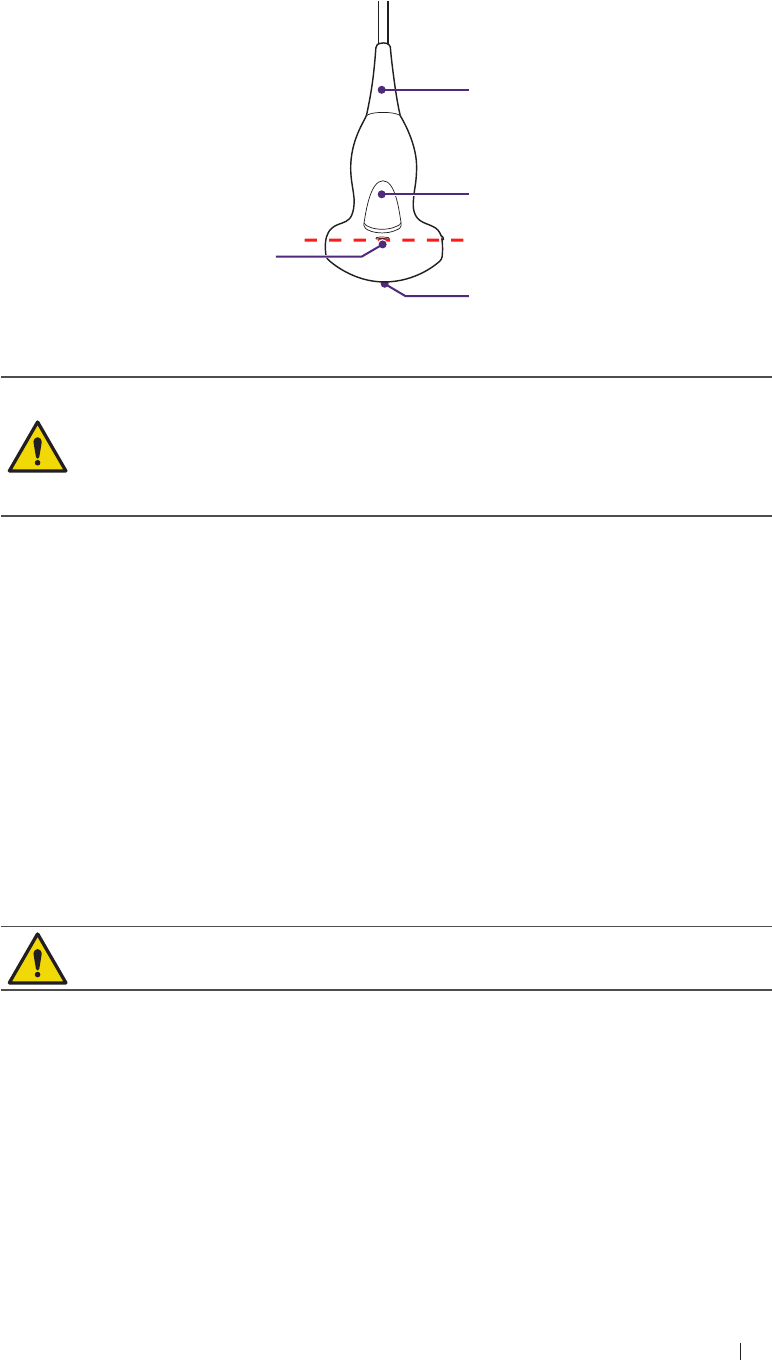
Transducer immersion level
When using surface transducers, do not immerse the transducer beyond
its immersion line.
Cable sheath
Transducer
handle
Scan head
Immersion
line
Figure 3 Surface transducer (Example transducer-C52A)
Do not use solutions containing alcohol, mineral oil for cleaning or
disinfecting transducers.
Wear medical sterile gloves to prevent potential disease
transmission. Wear protective goggle if necessary.
Do not apply solutions containing ethyl oxides on the transducer.
Cleaning instructions
1. Disconnect the transducer from the system.
2. Remove all the coupling gel and clean the transducer with soft cloth
and flowing potable water.
3. If the transducer surface carries too much residue, remove all visible
residue with wet cloth soaked in mild soap water. Use wet soft cloth
to scrub the surface if dried residue exists. Remove all soap water
residue with damp cloth soaked in potable water.
4. Air dry or dry with a soft cloth.
Take extra care when cleaning the transducer surface. Avoid causing
damages to the transducer by excessive and forceful cleaning.
Disinfection instructions
The level of disinfection is directly related to the duration of contact with
the germicide. Legally marketed liquid chemical germicides (e.g. Cidex)
are highly recommended. Prepare use the germicides following the
manufacturer’s instructions.

84
Maintenance Transducer precautions and maintenance
The following statement from AIUM outlines instructions for cleaning the
intracavitary transducer:
AIUM Guidelines for Cleaning and Preparing Endocavitary Ultrasound
Transducers between Patients
Approved June 4, 2003
The purpose of this document is to provide guidance regarding the
cleaning and disinfection of transvaginal and transrectal ultrasound
transducers.
All sterilization / disinfection represents a statistical reduction in the
number of microbes present on a surface. Meticulous cleaning of the
instrument is the essential key to an initial reduction of the microbial /
organic load by at least 99%. This cleaning is followed by a disinfecting
procedure to ensure a high degree of protection from infectious disease
transmission, even if a disposable barrier covers the instrument during
use.
Medical instruments fall into different categories with respect to potential
for infection transmission. The most critical levels of instruments are
those that are intended to penetrate skin or mucous membranes. These
require sterilization. Less critical instruments (often called “semi-critical”
instruments) that simply come into contact with mucous membranes
such as fiber optic endoscopes require high-level disinfection rather than
sterilization.
Although endocavity ultrasound transducers might be considered even
less critical instruments because they are routinely protected by single
use disposable transducer covers, leakage rates of 0.9 % to 2 % for
condoms and 8 % to 81 % for commercial transducer covers have been
observed in recent studies. For maximum safety, one should therefore
perform high-level disinfection of the transducer between each use and
use a transducer cover or condom as an aid in keeping the transducer
clean.
There are four generally recognized categories of disinfection and
sterilization.
Sterilization is the complete elimination of all forms or microbial life
including spores and viruses.
Disinfection, the selective removal of microbial life, is divided into three
classes:
High-level disinfection includes destruction / removal of all
microorganisms except bacterial spores.
Mid-level disinfection includes inactivation of Mycobacterium
Tuberculosis, bacteria, most viruses, fungi, and some bacterial
spores.

85
Maintenance Transducer precautions and maintenance
Low-Level Disinfection includes destruction of most bacteria, some
viruses and some fungi. Low-level disinfection will not necessarily
inactivate Mycobacterium Tuberculosis or bacterial spores.
The following specific recommendations are made for the use of
endocavity transducers. Operators should also review the Centers
for Disease Control and Prevention document on sterilization and
disinfection of medical devices to be certain that their procedures
conform to the CDC principles for disinfection of patient care equipment.
Procedures for cleaning
1. After removing the transducer cover, use running water to remove
any residual gel or debris from the transducer.
2. Use a damp gauze pad or other soft cloth and a small amount of mild
non-abrasive liquid soap (household dishwashing liquid is ideal) to
thoroughly cleanse the transducer.
3. Use a small brush especially for crevices and areas of angulations
depending on the design of your particular transducer.
4. Rinse the transducer thoroughly with running water, and then dry the
transducer with a soft cloth or paper towel.
Procedures for disinfection
1. Follow the above cleaning procedures to clean the transducer first
with a detergent/water solution, and ensure all visible residues are
removed from the transducer.
2. Use high-level disinfectant to ensure further statistical reduction in
microbial load. Because of the potential invisible disruption of the
transducer sheath, additional high level disinfection with chemical
agents is necessary.
Examples of such high level disinfectants include but are not limited to:
2.4% to 3.2% Glutaraldehyde products (a variety of available
proprietary products including “Cidex”, “Metricide”, or “Procide”)
Non-glutaraldehyde agents including Cidex OPA (o-phthalaldehyde),
Cidex PA (hydrogen peroxide & peroxyacetic acid).
7.5% Hydrogen Peroxide solution
Common household bleach (5.25% sodium hypochlorite) diluted to
yield 500 parts per million chlorine (10 cc in one liter of tap water).
This agent is effective, but generally not recommended by transducer
manufacturers because it can damage metal and plastic parts.

86
Maintenance Transducer precautions and maintenance
Other agents such as quaternary ammonium compounds are
not considered high level disinfectants and should not be used.
Isopropanol is not a high level disinfectant when used as a wipe
and transducer manufacturers generally do not recommend soaking
transducers in the liquid.
The FDA has published a list of approved sterilant and high level
disinfectants for use in processing reusable medical and dental
devices. Consult the list to find agents that may be useful for
transducer disinfection.
3. Operators should follow the instructions of proprietary products to
prepare, store and use the disinfectant. Regarding the compatibility
of these agents with transducers, consult the manufacturers. Many
of the chemical disinfectants are potentially toxic and many require
adequate precautions, such as proper ventilation, personal protective
devices (gloves, face/eye protection, etc.) and rinsing before reusing
the transducer.
Transducer sheath
When using E94A endocavity transducers, the transducers must be
protected with a transducer sheath. If condoms are used, they should
be non-lubricated and non-medicated. Operators should be aware that
condoms have been shown to be less prone to leakage than commercial
transducer covers, and have a six-fold enhanced AQL (acceptable
quality level) when compared to standard examination gloves. They
have an AQL equal to that of surgical gloves. Operators should be
aware of latex-sensitivity issues and have available nonlatex-containing
barriers.
Aseptic technique
For the protection of the patient and the health care worker, all
endocavitary examinations should be performed by the operator
wearing gloves properly throughout the ultrasound diagnostic process.
Gloves should be used to remove the condom or other barrier from the
transducer and to wash the transducer as mentioned above. As the
transducer sheath is removed, care should be taken not to contaminate
the transducer with secretions from the patient. At the completion of the
procedure, hands should be thoroughly washed with soap and water.
Do not use high pressure steam to disinfect the transducer.
Do not use thermal disinfection. Temperatures higher than 66°C or
150°F will damage the transducer.

87
Maintenance Transducer precautions and maintenance
Obvious disruption in condom integrity does not require modification
of this protocol. These guidelines take into account possible
transducer contamination due to a disruption in the barrier sheath.
In summary, routine high-level disinfection of the endocavity
transducer between patients, plus the use of a transducer cover
or condom during each examination is required to properly protect
patients from infection during endocavitary examinations.
Ensure that all visible residues have been removed.
Prepare the germicide solutions according to the manufacturer’s
instructions. Please also follow the manufacturer’s instructions for
storage and disposal of the germicide.
Immerse the transducer head into the germicide for time interval
specified by the germicide manufacturer. The immersion level
should be kept below the binding line. Note that you may need to
rotate and shake the transducer in order to remove the air bubbles
between the transducer surface and germicide solution.
After removing the transducer from the germicide solution, rinse it
thoroughly with clean, potable water to remove all visible germicide.
Dry the transducer with a soft cloth.

Appendix Acoustic output Reporting for Track 3
1 Appendix
Acoustic output Reporting for Track 3
Qisda Corporation follows Track 3 of the FDA’s information for
manufacturers seeking marketing clearance of diagnostic ultrasound
systems and transducers. Track 3 does not require evaluation of
acoustic output on an application-specific basis, but the global maximum
derated ISPTA must not exceed 720 mW/cm2 and the global maximum
MI must not exceed 1.9.
8
88

Appendix Acoustic output Reporting for Track 3
Acoustic output tables for UH100 Transducers
Acoustic output reporting table for Track 3 for the C52A transducer
UH100 Diagnostic Ultrasound System in B mode
Index label MI
TIS TIB
TIC
Scan Non-scan
Aaprt ≤ 1 cm2Aaprt > 1 cm2
Global maximum index value 0.0282 0.088 # # # (b)
Associated
acoustic
parameter
Pr.3 (MPa) 0.053
W0(mW) 24.4 # # #
Min of W.3(z1),
ITA.3(z1)] (mW) #
z1(cm) #
zbp (cm) #
zsp (cm) #
z@PII.3max (cm) 5.9
deq(zsp) (cm) #
fc(MHz) 3.5 3.5 # # # #
Dim of Aaprt
X (cm) 2.25 # # # #
Y (cm) 1.1 # # # #
Other
information
PD (microsec) 0.37
PRF (Hz) 5900
pr@PIImax (MPa) 0.109
deq@PIImax (cm) #
Focal length FLx (cm) 7 # # #
FLy (cm) 7 # # #
Ipa.3 at MImax (W/cm2) 0.09
Operating
control
conditions
Control 1 B B # # # #
Control 2 7 cm 7 cm # # # #
Control 3 5917 5917 # # # #
Control 4 100% 100% # # # #
# No data are reported for this operating condition since the global
maximum index value is not reported for the reason listed.
(a) This index is not required for this operating mode.
(b) This transducer is not intended for transcranial or neonatal
cephalic uses.
(c) This formulation for TIS is less than that for an alternate
formulation in this mode.
(d) Control 1: Mode
(e) Control 2: Focal distance
(f) Control 3: PRF
(g) Control 4: Power
89

Appendix Acoustic output Reporting for Track 3
Acoustic output reporting table for Track 3 for the C52A transducer
UH100 Diagnostic Ultrasound System in CFM-B mode
Index label MI
TIS TIB
TIC
Scan Non-scan
Aaprt ≤ 1 cm2Aaprt > 1 cm2
Global maximum index value 0.132 0.138 # # # (b)
Associated
acoustic
parameter
Pr.3 (MPa) 0.209
W0(mW) 58 # # #
Min of W.3(z1),
ITA.3(z1)] (mW) #
z1(cm) #
zbp (cm) #
zsp (cm) #
z@PII.3max (cm) 4.6
deq(zsp) (cm) #
fc(MHz) 2.5 2.5 # # # #
Dim of Aaprt
X (cm) 2.25 # # # #
Y (cm) 1.1 # # # #
Other
information
PD (microsec) 1.5
PRF (Hz) 5000
pr@PIImax (MPa) 0.303
deq@PIImax (cm) #
Focal length FLx (cm) 5 # # #
FLy (cm) 7 # # #
Ipa.3 at MImax (W/cm2) 2.96
Operating
control
conditions
Control 1 CFM CFM # # # #
Control 2 5 cm 5 cm # # # #
Control 3 5 KHz 5 KHz # # # #
Control 4 100% 100% # # # #
# No data are reported for this operating condition since the global
maximum index value is not reported for the reason listed.
(a) This index is not required for this operating mode.
(b) This transducer is not intended for transcranial or neonatal
cephalic uses.
(c) This formulation for TIS is less than that for an alternate
formulation in this mode.
(d) Control 1: Mode
(e) Control 2: Focal distance
(f) Control 3: PRF
(g) Control 4: Power
90

Appendix Acoustic output Reporting for Track 3
Acoustic output reporting table for Track 3 for the C52A transducer
UH100 Diagnostic Ultrasound System in B/M mode
Index label MI
TIS TIB
TIC
Scan Non-scan
Aaprt ≤ 1 cm2Aaprt > 1 cm2
Global maximum index value 0.133 # # 0.0199 0.077 (b)
Associated
acoustic
parameter
Pr.3 (MPa) 0.246
W0(mW) # # 37 #
Min of W.3(z1),
ITA.3(z1)] (mW) 1.23
z1(cm) 5
zbp (cm) 2.66
zsp (cm) 4.5
z@PII.3max (cm) 5
deq(zsp) (cm) 3.4
fc(MHz) 3.4 # # 3.4 3.4 #
Dim of Aaprt
X (cm) # # 2.25 2.25 #
Y (cm) # # 1.1 1.1 #
Other
information
PD (microsec) 1.2
PRF (Hz) 250
pr@PIImax (MPa) 0.47
deq@PIImax (cm) 3.2
Focal length FLx (cm) # # 7 #
FLy (cm) # # 7 #
Ipa.3 at MImax (W/cm2) 3.4
Operating
control
conditions
Control 1 M # # M M #
Control 2 7 cm # # 7 cm 7 cm #
Control 3 250 # # 250 250 #
Control 4 100% # # 100% 100% #
# No data are reported for this operating condition since the global
maximum index value is not reported for the reason listed.
(a) This index is not required for this operating mode.
(b) This transducer is not intended for transcranial or neonatal
cephalic uses.
(c) This formulation for TIS is less than that for an alternate
formulation in this mode.
(d) Control 1: Mode
(e) Control 2: Focal distance
(f) Control 3: PRF
(g) Control 4: Power
91

Appendix Acoustic output Reporting for Track 3
Acoustic output reporting table for Track 3 for the C52A transducer
UH100 Diagnostic Ultrasound System in PW mode
Index label MI
TIS TIB
TIC
Scan Non-scan
Aaprt ≤ 1 cm2Aaprt > 1 cm2
Global maximum index value 0.127 # # 0.209 0.52 (b)
Associated
acoustic
parameter
Pr.3 (MPa) 0.241
W0(mW) # # 165 #
Min of W.3(z1),
ITA.3(z1)] (mW) 12.1
z1(cm) 5
zbp (cm) 2.66
zsp (cm) 4.2
z@PII.3max (cm) 5
deq(zsp) (cm) 2.22
fc(MHz) 3.6 # # 3.6 3.6 #
Dim of Aaprt
X (cm) # # 2.25 2.25 #
Y (cm) # # 1.1 1.1 #
Other
information
PD (microsec) 1.08
PRF (Hz) 3000
pr@PIImax (MPa) 0.43
deq@PIImax (cm) 2.1
Focal length FLx (cm) # # 7 #
FLy (cm) # # 7 #
Ipa.3 at MImax (W/cm2) 2.84
Operating
control
conditions
Control 1 PW # # PW PW #
Control 2 7 cm # # 7 cm 7 cm #
Control 3 3000 # # 3000 3000 #
Control 4 100% # # 100% 100% #
# No data are reported for this operating condition since the global
maximum index value is not reported for the reason listed.
(a) This index is not required for this operating mode.
(b) This transducer is not intended for transcranial or neonatal
cephalic uses.
(c) This formulation for TIS is less than that for an alternate
formulation in this mode.
(d) Control 1: Mode
(e) Control 2: Focal distance
(f) Control 3: PRF
(g) Control 4: Power
92

Appendix Acoustic output Reporting for Track 3
Acoustic output reporting table for Track 3 for the L115A
transducer
UH100 Diagnostic Ultrasound System in B mode
Index label MI
TIS TIB
TIC
Scan Non-scan
Aaprt ≤ 1 cm2Aaprt > 1 cm2
Global maximum index value 0.055 0.07 # # # (b)
Associated
acoustic
parameter
Pr.3 (MPa) 0.142
W0(mW) 1.4 # # #
Min of W.3(z1),
ITA.3(z1)] (mW) #
z1(cm) #
zbp (cm) #
zsp (cm) #
z@PII.3max (cm) 1.79
deq(zsp) (cm) #
fc(MHz) 6.7 6.7 # # # #
Dim of Aaprt
X (cm) 0.6 # # # #
Y (cm) 0.6 # # # #
Other
information
PD (microsec) 0.183
PRF (Hz) 9800
pr@PIImax (MPa) 0.209
deq@PIImax (cm) #
Focal length FLx (cm) 1.5 # # #
FLy (cm) 1.9 # # #
Ipa.3 at MImax (W/cm2) 1.13
Operating
control
conditions
Control 1 B B # # # #
Control 2 1.5 cm 1.5 cm # # # #
Control 3 9804 9804 # # # #
Control 4 100% 100% # # # #
# No data are reported for this operating condition since the global
maximum index value is not reported for the reason listed.
(a) This index is not required for this operating mode.
(b) This transducer is not intended for transcranial or neonatal
cephalic uses.
(c) This formulation for TIS is less than that for an alternate
formulation in this mode.
(d) Control 1: Mode
(e) Control 2: Focal distance
(f) Control 3: PRF
(g) Control 4: Power
93

Appendix Acoustic output Reporting for Track 3
Acoustic output reporting table for Track 3 for the L115A
transducer
UH100 Diagnostic Ultrasound System in CFM-B mode
Index label MI
TIS TIB
TIC
Scan Non-scan
Aaprt ≤ 1 cm2Aaprt > 1 cm2
Global maximum index value 0.107 0.188 # # # (b)
Associated
acoustic
parameter
Pr.3 (MPa) 0.237
W0(mW) 32 # # #
Min of W.3(z1),
ITA.3(z1)] (mW) #
z1(cm) #
zbp (cm) #
zsp (cm) #
z@PII.3max (cm) 2.57
deq(zsp) (cm) #
fc(MHz) 4.9 4.9 # # # #
Dim of Aaprt
X (cm) 3.8 # # # #
Y (cm) 0.6 # # # #
Other
information
PD (microsec) 0.81
PRF (Hz) 3000
pr@PIImax (MPa) 0.37
deq@PIImax (cm) #
Focal length FLx (cm) 1.5 # # #
FLy (cm) 1.9 # # #
Ipa.3 at MImax (W/cm2) 5.6
Operating
control
conditions
Control 1 CFM CFM # # # #
Control 2 3 cm 3 cm # # # #
Control 3 3 KHz 3 KHz # # # #
Control 4 100% 100% # # # #
# No data are reported for this operating condition since the global
maximum index value is not reported for the reason listed.
(a) This index is not required for this operating mode.
(b) This transducer is not intended for transcranial or neonatal
cephalic uses.
(c) This formulation for TIS is less than that for an alternate
formulation in this mode.
(d) Control 1: Mode
(e) Control 2: Focal distance
(f) Control 3: PRF
(g) Control 4: Power
94

Appendix Acoustic output Reporting for Track 3
Acoustic output reporting table for Track 3 for the L115A
transducer
UH100 Diagnostic Ultrasound System in B/M mode
Index label MI
TIS TIB
TIC
Scan Non-scan
Aaprt ≤ 1 cm2Aaprt > 1 cm2
Global maximum index value 0.13 # 0.36 # 0.047 (b)
Associated
acoustic
parameter
Pr.3 (MPa) 0.35
W0(mW) # 10.7 10.7 #
Min of W.3(z1),
ITA.3(z1)] (mW) #
z1(cm) #
zbp (cm) #
zsp (cm) 2.01
z@PII.3max (cm) 2.11
deq(zsp) (cm) 1.85
fc(MHz) 7.1 # 7.1 # 7.1 #
Dim of Aaprt
X (cm) # 0.71 # 0.71 #
Y (cm) # 0.6 # 0.6 #
Other
information
PD (microsec) 0.68
PRF (Hz) 250
pr@PIImax (MPa) 0.58
deq@PIImax (cm) 1.82
Focal length FLx (cm) # 1.5 # #
FLy (cm) # 1.9 # #
Ipa.3 at MImax (W/cm2) 7.7
Operating
control
conditions
Control 1 M # # M M #
Control 2 3 cm # # 3 cm 3 cm #
Control 3 250 # # 250 250 #
Control 4 100% # # 100% 100% #
# No data are reported for this operating condition since the global
maximum index value is not reported for the reason listed.
(a) This index is not required for this operating mode.
(b) This transducer is not intended for transcranial or neonatal
cephalic uses.
(c) This formulation for TIS is less than that for an alternate
formulation in this mode.
(d) Control 1: Mode
(e) Control 2: Focal distance
(f) Control 3: PRF
(g) Control 4: Power
95

Appendix Acoustic output Reporting for Track 3
Acoustic output reporting table for Track 3 for the L115A
transducer
UH100 Diagnostic Ultrasound System in PW mode
Index label MI
TIS TIB
TIC
Scan Non-scan
Aaprt ≤ 1 cm2Aaprt > 1 cm2
Global maximum index value 0.1 # 1.18 # 0.38 (b)
Associated
acoustic
parameter
Pr.3 (MPa) 0.27
W0(mW) # 34 34 #
Min of W.3(z1),
ITA.3(z1)] (mW) #
z1(cm) #
zbp (cm) #
zsp (cm) 2.06
z@PII.3max (cm) 2.15
deq(zsp) (cm) 0.71
fc(MHz) 7.3 # 7.3 # 7.3 #
Dim of Aaprt
X (cm) # 0.41 # 0.41 #
Y (cm) # 0.6 # 0.6 #
Other
information
PD (microsec) 1.03
PRF (Hz) 4000
pr@PIImax (MPa) 0.46
deq@PIImax (cm) 0.69
Focal length FLx (cm) # 1.5 # #
FLy (cm) # 1.9 # #
Ipa.3 at MImax (W/cm2) 6.4
Operating
control
conditions
Control 1 PW # PW # PW #
Control 2 3 cm # 3 cm # 3 cm #
Control 3 4000 # 4000 # 4000 #
Control 4 100% # 100% # 100% #
# No data are reported for this operating condition since the global
maximum index value is not reported for the reason listed.
(a) This index is not required for this operating mode.
(b) This transducer is not intended for transcranial or neonatal
cephalic uses.
(c) This formulation for TIS is less than that for an alternate
formulation in this mode.
(d) Control 1: Mode
(e) Control 2: Focal distance
(f) Control 3: PRF
(g) Control 4: Power
96

Appendix Acoustic output Reporting for Track 3
Acoustic output reporting table for Track 3 for the P42A transducer
UH100 Diagnostic Ultrasound System in B mode
Index label MI
TIS TIB
TIC
Scan Non-scan
Aaprt ≤ 1 cm2Aaprt > 1 cm2
Global maximum index value 0.149 0.39 # # # (b)
Associated
acoustic
parameter
Pr.3 (MPa) 0.235
W0(mW) 44 # # #
Min of W.3(z1),
ITA.3(z1)] (mW) #
z1(cm) #
zbp (cm) #
zsp (cm) #
z@PII.3max (cm) 5.7
deq(zsp) (cm) #
fc(MHz) 2.48 2.48 # # # #
Dim of Aaprt
X (cm) 1.92 # # # #
Y (cm) 1.4 # # # #
Other
information
PD (microsec) 0.53
PRF (Hz) 5600
pr@PIImax (MPa) 0.35
deq@PIImax (cm) #
Focal length FLx (cm) 6 # # #
FLy (cm) 8 # # #
Ipa.3 at MImax (W/cm2) 2.14
Operating
control
conditions
Control 1 B B # # # #
Control 2 6 cm 6 cm # # # #
Control 3 5555 5555 # # # #
Control 4 100% 100% # # # #
# No data are reported for this operating condition since the global
maximum index value is not reported for the reason listed.
(a) This index is not required for this operating mode.
(b) This transducer is not intended for transcranial or neonatal
cephalic uses.
(c) This formulation for TIS is less than that for an alternate
formulation in this mode.
(d) Control 1: Mode
(e) Control 2: Focal distance
(f) Control 3: PRF
(g) Control 4: Power
97

Appendix Acoustic output Reporting for Track 3
Acoustic output reporting table for Track 3 for the P42A transducer
UH100 Diagnostic Ultrasound System in CFM-B mode
Index label MI
TIS TIB
TIC
Scan Non-scan
Aaprt ≤ 1 cm2Aaprt > 1 cm2
Global maximum index value 0.205 1.74 # # # (b)
Associated
acoustic
parameter
Pr.3 (MPa) 0.32
W0(mW) 207 # # #
Min of W.3(z1),
ITA.3(z1)] (mW) #
z1(cm) #
zbp (cm) #
zsp (cm) #
z@PII.3max (cm) 5.1
deq(zsp) (cm) #
fc(MHz) 2.48 2.48 # # # #
Dim of Aaprt
X (cm) 1.92 # # # #
Y (cm) 1.4 # # # #
Other
information
PD (microsec) 1.46
PRF (Hz) 2000
pr@PIImax (MPa) 0.49
deq@PIImax (cm) #
Focal length FLx (cm) 6 # # #
FLy (cm) 8 # # #
Ipa.3 at MImax (W/cm2) 5.5
Operating
control
conditions
Control 1 CFM CFM # # # #
Control 2 7 cm 7 cm # # # #
Control 3 2 KHz 2 KHz # # # #
Control 4 100% 100% # # # #
# No data are reported for this operating condition since the global
maximum index value is not reported for the reason listed.
(a) This index is not required for this operating mode.
(b) This transducer is not intended for transcranial or neonatal
cephalic uses.
(c) This formulation for TIS is less than that for an alternate
formulation in this mode.
(d) Control 1: Mode
(e) Control 2: Focal distance
(f) Control 3: PRF
(g) Control 4: Power
98

Appendix Acoustic output Reporting for Track 3
Acoustic output reporting table for Track 3 for the P42A transducer
UH100 Diagnostic Ultrasound System in B/M mode
Index label MI
TIS TIB
TIC
Scan Non-scan
Aaprt ≤ 1 cm2Aaprt > 1 cm2
Global maximum index value 0.242 # # 0.043 0.207 (b)
Associated
acoustic
parameter
Pr.3 (MPa) 0.38
W0(mW) # # 67 #
Min of W.3(z1),
ITA.3(z1)] (mW) 3.6
z1(cm) 4.8
zbp (cm) 2.77
zsp (cm) 4.6
z@PII.3max (cm) 4.8
deq(zsp) (cm) 3.2
fc(MHz) 2.48 # # 2.48 2.48 #
Dim of Aaprt
X (cm) # # 1.92 1.92 #
Y (cm) # # 1.4 1.4 #
Other
information
PD (microsec) 1.49
PRF (Hz) 250
pr@PIImax (MPa) 0.56
deq@PIImax (cm) 3.12
Focal length FLx (cm) # # 6 #
FLy (cm) # # 8 #
Ipa.3 at MImax (W/cm2) 9.5
Operating
control
conditions
Control 1 M # # M M #
Control 2 7 cm # # 7 cm 7 cm #
Control 3 250 # # 250 250 #
Control 4 100% # # 100% 100% #
# No data are reported for this operating condition since the global
maximum index value is not reported for the reason listed.
(a) This index is not required for this operating mode.
(b) This transducer is not intended for transcranial or neonatal
cephalic uses.
(c) This formulation for TIS is less than that for an alternate
formulation in this mode.
(d) Control 1: Mode
(e) Control 2: Focal distance
(f) Control 3: PRF
(g) Control 4: Power
99

Appendix Acoustic output Reporting for Track 3
Acoustic output reporting table for Track 3 for the P42A transducer
UH100 Diagnostic Ultrasound System in PW mode
Index label MI
TIS TIB
TIC
Scan Non-scan
Aaprt ≤ 1 cm2Aaprt > 1 cm2
Global maximum index value 0.248 # # 0.77 2 (b)
Associated
acoustic
parameter
Pr.3 (MPa) 0.39
W0(mW) # # 340 #
Min of W.3(z1),
ITA.3(z1)] (mW) 65
z1(cm) 4.8
zbp (cm) 2.77
zsp (cm) 4.5
z@PII.3max (cm) 4.8
deq(zsp) (cm) 1.72
fc(MHz) 2.48 # # 2.48 2.48 #
Dim of Aaprt
X (cm) # # 1.92 1.92 #
Y (cm) # # 1.4 1.4 #
Other
information
PD (microsec) 1.53
PRF (Hz) 4000
pr@PIImax (MPa) 0.59
deq@PIImax (cm) 1.69
Focal length FLx (cm) # # 6 #
FLy (cm) # # 8 #
Ipa.3 at MImax (W/cm2) 10.9
Operating
control
conditions
Control 1 PW # # PW PW #
Control 2 7 cm # # 7 cm 7 cm #
Control 3 4000 # # 4000 4000 #
Control 4 100% # # 100% 100% #
# No data are reported for this operating condition since the global
maximum index value is not reported for the reason listed.
(a) This index is not required for this operating mode.
(b) This transducer is not intended for transcranial or neonatal
cephalic uses.
(c) This formulation for TIS is less than that for an alternate
formulation in this mode.
(d) Control 1: Mode
(e) Control 2: Focal distance
(f) Control 3: PRF
(g) Control 4: Power
100

Appendix Acoustic output Reporting for Track 3
Acoustic output reporting table for Track 3 for the E94A transducer
UH100 Diagnostic Ultrasound System in B mode
Index label MI
TIS TIB
TIC
Scan Non-scan
Aaprt ≤ 1 cm2Aaprt > 1 cm2
Global maximum index value 0.109 0.069 # # # (b)
Associated
acoustic
parameter
Pr.3 (MPa) 0.266
W0(mW) 4.1 # # #
Min of W.3(z1),
ITA.3(z1)] (mW) #
z1(cm) #
zbp (cm) #
zsp (cm) #
z@PII.3max (cm) 2.47
deq(zsp) (cm) #
fc(MHz) 6 6 # # # #
Dim of Aaprt
X (cm) 1.75 # # # #
Y (cm) 0.6 # # # #
Other
information
PD (microsec) 0.216
PRF (Hz) 7000
pr@PIImax (MPa) 0.44
deq@PIImax (cm) #
Focal length FLx (cm) 3.5 # # #
FLy (cm) 2.6 # # #
Ipa.3 at MImax (W/cm2) 3.9
Operating
control
conditions
Control 1 B B # # # #
Control 2 3.5 cm 3.5 cm # # # #
Control 3 6973 6973 # # # #
Control 4 100% 100% # # # #
# No data are reported for this operating condition since the global
maximum index value is not reported for the reason listed.
(a) This index is not required for this operating mode.
(b) This transducer is not intended for transcranial or neonatal
cephalic uses.
(c) This formulation for TIS is less than that for an alternate
formulation in this mode.
(d) Control 1: Mode
(e) Control 2: Focal distance
(f) Control 3: PRF
(g) Control 4: Power
101

Appendix Acoustic output Reporting for Track 3
Acoustic output reporting table for Track 3 for the E94A transducer
UH100 Diagnostic Ultrasound System in CFM-B mode
Index label MI
TIS TIB
TIC
Scan Non-scan
Aaprt ≤ 1 cm2Aaprt > 1 cm2
Global maximum index value 0.113 0.195 # # # (b)
Associated
acoustic
parameter
Pr.3 (MPa) 0.284
W0(mW) 13.2 # # #
Min of W.3(z1),
ITA.3(z1)] (mW) #
z1(cm) #
zbp (cm) #
zsp (cm) #
z@PII.3max (cm) 2.02
deq(zsp) (cm) #
fc(MHz) 6.3 6.3 # # # #
Dim of Aaprt
X (cm) 1.75 # # # #
Y (cm) 0.6 # # # #
Other
information
PD (microsec) 0.48
PRF (Hz) 3010
pr@PIImax (MPa) 0.43
deq@PIImax (cm) #
Focal length FLx (cm) 2.5 # # #
FLy (cm) 2.6 # # #
Ipa.3 at MImax (W/cm2) 7.6
Operating
control
conditions
Control 1 CFM CFM # # # #
Control 2 2.5 cm 2.5 cm # # # #
Control 3 3 KHz 3 KHz # # # #
Control 4 100% 100% # # # #
# No data are reported for this operating condition since the global
maximum index value is not reported for the reason listed.
(a) This index is not required for this operating mode.
(b) This transducer is not intended for transcranial or neonatal
cephalic uses.
(c) This formulation for TIS is less than that for an alternate
formulation in this mode.
(d) Control 1: Mode
(e) Control 2: Focal distance
(f) Control 3: PRF
(g) Control 4: Power
102

Appendix Acoustic output Reporting for Track 3
Acoustic output reporting table for Track 3 for the E94A transducer
UH100 Diagnostic Ultrasound System in B/M mode
Index label MI
TIS TIB
TIC
Scan Non-scan
Aaprt ≤ 1 cm2Aaprt > 1 cm2
Global maximum index value 0.15 # # 0.049 0.034 (b)
Associated
acoustic
parameter
Pr.3 (MPa) 0.37
W0(mW) # # 4 #
Min of W.3(z1),
ITA.3(z1)] (mW) 1.64
z1(cm) 1.96
zbp (cm) 1.73
zsp (cm) 1.82
z@PII.3max (cm) 1.96
deq(zsp) (cm) 3.4
fc(MHz) 6.3 # # 6.3 6.3 #
Dim of Aaprt
X (cm) # # 1.75 1.75 #
Y (cm) # # 0.6 0.6 #
Other
information
PD (microsec) 0.62
PRF (Hz) 250
pr@PIImax (MPa) 0.55
deq@PIImax (cm) 1.14
Focal length FLx (cm) # # 2.5 #
FLy (cm) # # 2.6 #
Ipa.3 at MImax (W/cm2) 12.3
Operating
control
conditions
Control 1 M # # M M #
Control 2 2.5 cm # # 2.5 cm 2.5 cm #
Control 3 250 # # 250 250 #
Control 4 100% # # 100% 100% #
# No data are reported for this operating condition since the global
maximum index value is not reported for the reason listed.
(a) This index is not required for this operating mode.
(b) This transducer is not intended for transcranial or neonatal
cephalic uses.
(c) This formulation for TIS is less than that for an alternate
formulation in this mode.
(d) Control 1: Mode
(e) Control 2: Focal distance
(f) Control 3: PRF
(g) Control 4: Power
103

Appendix Acoustic output Reporting for Track 3
Acoustic output reporting table for Track 3 for the E94A transducer
UH100 Diagnostic Ultrasound System in PW mode
Index label MI
TIS TIB
TIC
Scan Non-scan
Aaprt ≤ 1 cm2Aaprt > 1 cm2
Global maximum index value 0.153 # 0.84 # 0.32 (b)
Associated
acoustic
parameter
Pr.3 (MPa) 0.38
W0(mW) # 28.1 28.1 #
Min of W.3(z1),
ITA.3(z1)] (mW) #
z1(cm) #
zbp (cm) #
zsp (cm) 1.82
z@PII.3max (cm) 1.93
deq(zsp) (cm) 0.86
fc(MHz) 6.3 # 6.3 # 6.3 #
Dim of Aaprt
X (cm) # 1.14 # 1.14 #
Y (cm) # 0.6 # 0.6 #
Other
information
PD (microsec) 0.62
PRF (Hz) 3000
pr@PIImax (MPa) 0.56
deq@PIImax (cm) 0.84
Focal length FLx (cm) # 2.5 # #
FLy (cm) # 2.6 # #
Ipa.3 at MImax (W/cm2) 11.4
Operating
control
conditions
Control 1 PW # # PW PW #
Control 2 2.5 cm # # 2.5 cm 2.5 cm #
Control 3 3000 # # 3000 3000 #
Control 4 100% # # 100% 100% #
# No data are reported for this operating condition since the global
maximum index value is not reported for the reason listed.
(a) This index is not required for this operating mode.
(b) This transducer is not intended for transcranial or neonatal
cephalic uses.
(c) This formulation for TIS is less than that for an alternate
formulation in this mode.
(d) Control 1: Mode
(e) Control 2: Focal distance
(f) Control 3: PRF
(g) Control 4: Power
104
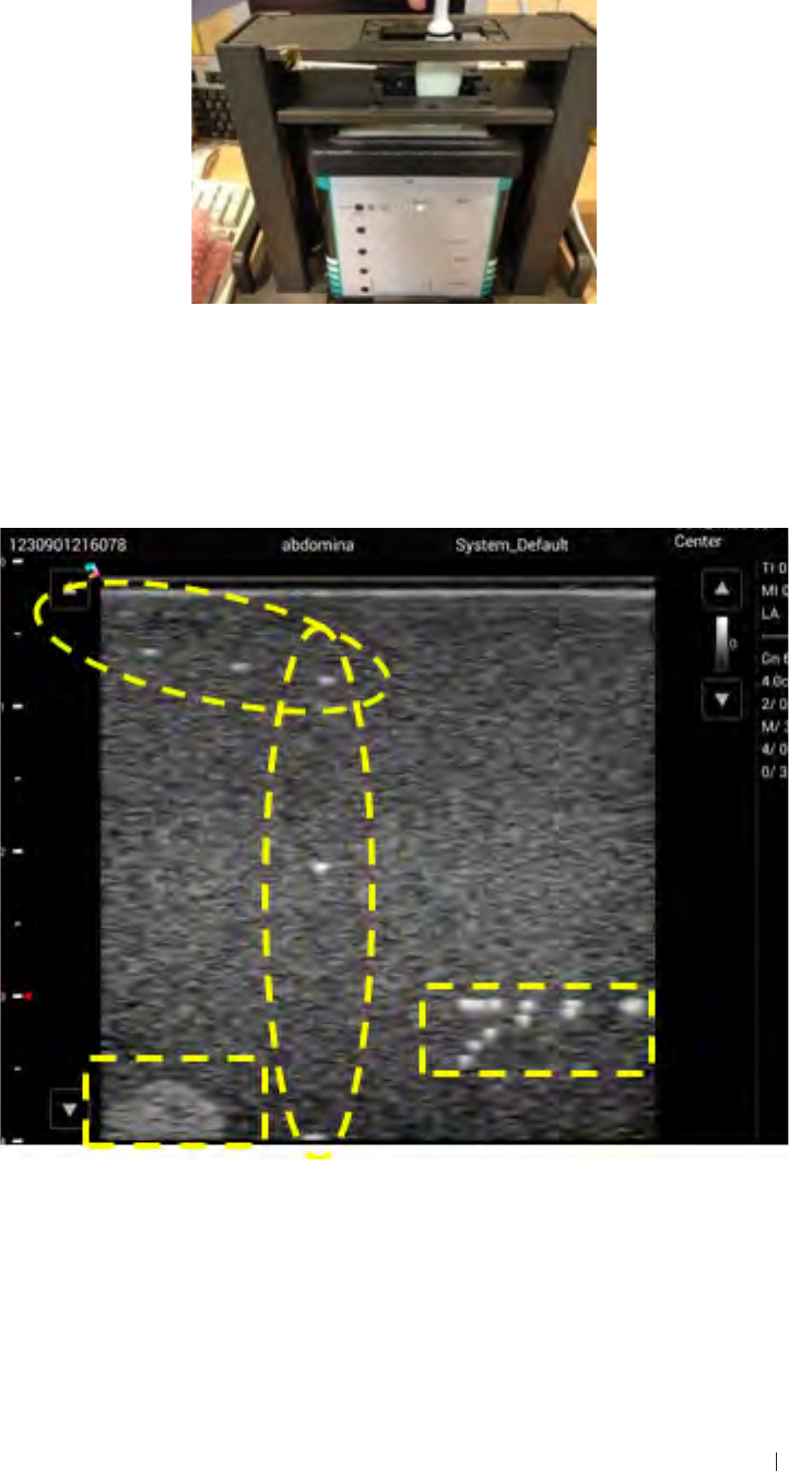
Appendix Ultrasound validation
Ultrasound validation
1. Set up the phantom for validation. Make sure the notch is filled with
some water.
2. Insert the transducer for ultrasound validation.
3. Initiate the ultrasound software. Confirm Ultrasound software has
scanned images as below photos. You can see the bright dot on
Phantom, and the background should be the same speckle without
any particular dark lines or streaks.
105
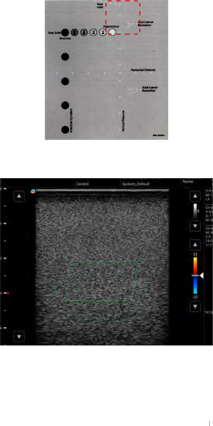
Appendix Ultrasound validation
The actual scan area of the phantom is shown as the image below.
4. Touch Color to switch to Color Doppler mode and keep the
transducer stationary. Confirm there is no stationary color image
signal in the Green block area as the photo below.
106
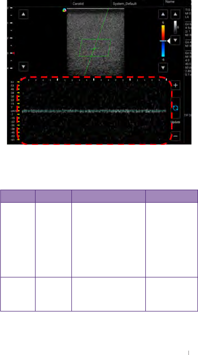
Appendix Troubleshooting
5. Touch PW to switch to PW Doppler mode and keep the transducer
stationary. Confirm the picture is evenly distributed without any
particular waveform signal as the photo below.
6. Remove the transducer.
Troubleshooting
Item Error
description Possible root cause Possible swap parts
System -
Power on System can’t
power on 1. SOM board damage
2. Carrier board damage
3. Screen off / Screen cable
damage
4. Battery no power (can
charge Battery) / Battery
damage (can use adapter
to check)
5. Disconnect gauge cable
6. Disconnect bottom cable /
bottom board damage
1. SOM board
2. Carrier board
3. LCD / LCD cable
4. Battery
5. Connect gauge
cable
6. Bottom cable/
board
System -
Charging System can’t
charge 1. Power supply damage
2. Adapter damage
3. Carrier board damage
4. Gauge cable / connector
damage
1. Power supply
2. Adapter
3. Carrier board
4. Gauge cable /
connector
107

Appendix Troubleshooting
Item Error
description Possible root cause Possible swap parts
System -
eMMC Can’t read
and write date
from eMMC
SOM board damage SOM board
System -
SD card Can’t read
and write data
from SD card
1. SOM board damage
2. Carrier board damage 1. SOM board
2. Carrier board
System -
USB 2.0 Can’t read
and write data
from USB 2.0
1. SOM board damage
2. Carrier board damage 1. SOM board
2. Carrier board
System -
USB 3.0 Can’t read
and write data
from USB 3.0
1. SOM board damage
2. Carrier board damage 1. SOM board
2. Carrier board
System -
mSATA Can’t read
and write data
from mSATA
1. SOM board damage
2. Carrier board damage
3. mSATA module damage
1. SOM board
2. Carrier board
3. mSATA
System -
System fan System fan
can’t work 1. System fan damage
2. Carrier board damage 1. System fan
2. Carrier board
System -
Engine fan Engine fan
can’t work 1. Engine fan damage
2. Carrier board damage 1. Engine fan
2. Carrier board
System -
Ethernet Ethernet not
function 1. SOM board damage
2. Carrier board damage 1. SOM board
2. Carrier board
System -
OTG OTG not
function 1. SOM board damage
2. Carrier board damage 1. SOM board
2. Carrier board
System -
LCD LCD screen
abnormal or
no display
1. LCD damage
2. LCD cable damage
3. SOM board damage
4. Carrier board damage
1. LCD module
2. LCD cable
3. SOM board
4. Carrier board
System -
Touch Touch not
function or
abnormal
1. Touch module damage
2. Touch control board
damage
3. Touch cable disconnect
or damage
4. SOM board damage
5. Carrier board damage
1. LCD (including
touch module)
2. Touch control
board
3. Touch cable
4. SOM board
5. Carrier board
System -
Camera Camera
not function
or display
abnormally
1. Camera PCBA damage
2. Camera cable disconnect
or damage
3. SOM board damage
4. Carrier board damage
1. Camera PCBA
2. Camera cable
3. SOM board
4. Carrier board
System -
HDMI HDMI not
function or
abnormal
1. HDMI cable damage
2. SOM board damage
3. Carrier board damage
1. LCD cable
2. SOM board
3. Carrier board
System -
MIC Recording
no sound or
unclear
1. The received voice hole
of Mic is covered by
something
2. SOM board damage
3. Carrier board damage
1. Remove anything
that covered the
hole of mic
2. SOM board
3. Carrier board
108

Appendix FCC statement
Item Error
description Possible root cause Possible swap parts
System -
Speaker
Speaker no
sound or
noise when
playing sound
1. Speaker damage
2. SOM board damage
3. Carrier board damage
1. Speaker
2. SOM board
3. Carrier board
System -
Headset
Headset no
sound or
noise when
playing sound
1. Headset damage
2. SOM board damage
3. Carrier board damage
1. Headset
2. SOM board
3. Carrier board
System -
Power button
Power button
not function 1. Power button damage
2. SOM board damage
3. Carrier board damage
1. Power button
2. SOM board
3. Carrier board
System -
RTC RTC not
function 1. Coin cell damage
2. SOM board damage
3. Carrier board damage
1. Coin cell
2. SOM board
3. Carrier board
System -
Temperature Temperature
does not
show or
abnormal
1. SOM board damage
2. Carrier board damage 1. SOM board
2. Carrier board
System -
LED LED indicator
not function 1. SOM board damage
2. Carrier board damage 1. SOM board
2. Carrier board
System -
Wi-Fi Wireless not
response or
no connection
1. Antenna cable disconnect
or damage
2. Antenna board damage
3. SOM board damage
1. Antenna cable
2. Antenna board
3. SOM board
System -
Bluetooth Bluetooth not
response or
no connection
1. Antenna cable disconnect
or damage
2. Antenna board damage
3. SOM board damage
1. Antenna cable
2. Antenna board
3. SOM board
Engine Can’t open
ultrasound
app
1. SOM board damage
2. Carrier board damage
3. USB 3.0 cable (for
engine) damage
4. Power cable (for engine)
damage
1. SOM board
2. Carrier board
3. USB 3.0 cable
4. Power cable
FCC statement
Federal Communications Commission (FCC) Statement
15.21
You are cautioned that changes or modifications not expressly approved
by the part responsible for compliance could void the user’s authority to
operate the equipment.
15.105(b)
109

Appendix FCC statement
This equipment has been tested and found to comply with the limits for
a Class B digital device, pursuant to part 15 of the FCC rules. These
limits are designed to provide reasonable protection against harmful
interference in a residential installation.
This equipment generates uses and can radiate radio frequency energy
and, if not installed and used in accordance with the instructions, may
cause harmful interference to radio communications. However, there is
no guarantee that interference will not occur in a particular installation.
If this equipment does cause harmful interference to radio or television
reception, which can be determined by turning the equipment off and on,
the user is encouraged to try to correct the interference by one or more
of the following measures:
Reorient or relocate the receiving antenna.
Increase the separation between the equipment and receiver.
Connect the equipment into an outlet on a circuit different from that to
which the receiver is connected.
Consult the dealer or an experienced radio/TV technician for help.
This device complies with part 15 of the FCC Rules. Operation is subject
to the following two conditions:
1. This device may not cause interference and
2. This device must accept any interference, including interference that
may cause undesired operation of the device.
RF Radiation Exposure Statement:
1. This Transmitter must not be co-located or operating in conjunction
with any other antenna or transmitter.
2. This equipment complies with FCC RF radiation exposure limits set
forth for an uncontrolled environment. This equipment should be
installed and operated with a minimum distance of 20 centimeters
between the radiator and your body.
*CE
Statement regarding the disposal of UH100 products containing
electronic components:
110

Appendix FCC statement 111
As a company, UH100 is committed to sustainable business practices,
which are aimed to preserve, protect and improve the quality of
the environment. We apply these to product technologies, design
and the selection of the materials used in our products. Adhering to
corresponding environmental laws, directives and guidelines are a core
element of our sustainability principles. Since the UH100 concept is
equipped with electronic components, we will ensure that it complies
with actual or planned directives and laws, which are mandatory for
electronic products and may require specific measures regarding
labeling, collection and recycling.
NOTE: If not disposed of properly, batteries can be harmful. Protect
the environment by taking exhausted batteries to authorized disposal
stations.
European Commission (CE) Statement
European Union Regulatory Notice
This device bearing the CE marking is compliance with the essential
requirements and other relevant provisions of Directive 2004/108/EC,
2014/53/EU, 2011/65/EU, 2012/19/EU and 93/42/EEC.
This device complies with the following harmonized European standards,
EMC: EN55022, EN55024
Radio: EN300328,EN301893,EN301489-1,EN301489-17, EN62311
Medical: IEC 60601-1, EN60601-1-2, IEC 60601-1-6, IEC 60601-2-37,
IEC 62304, EN ISO10993-1, EN ISO10993-5, EN ISO10993-10, EN ISO
14971
ROHS: EN50581
The following CE marking is valid for EU harmonized telecommunications
products.