Qixiang Electron Science and Technology 8RSERIES FM HANDHELD TRANSCEIVER User Manual
Qixiang Electron Science& Technology Co., Ltd FM HANDHELD TRANSCEIVER
UserManual.wiki
>
Qixiang Electron Science and Technology
>
8RSERIES User Manual
User Manual
Navigation menu
Upload a User Manual
Namespaces
Wiki Guide
HTML
PDF
Info
Views
User Manual
Discussion / Help
Navigation


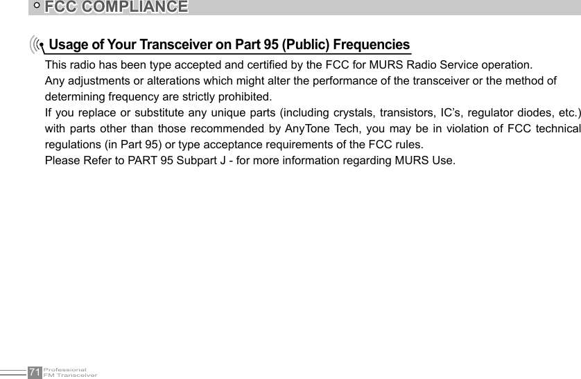
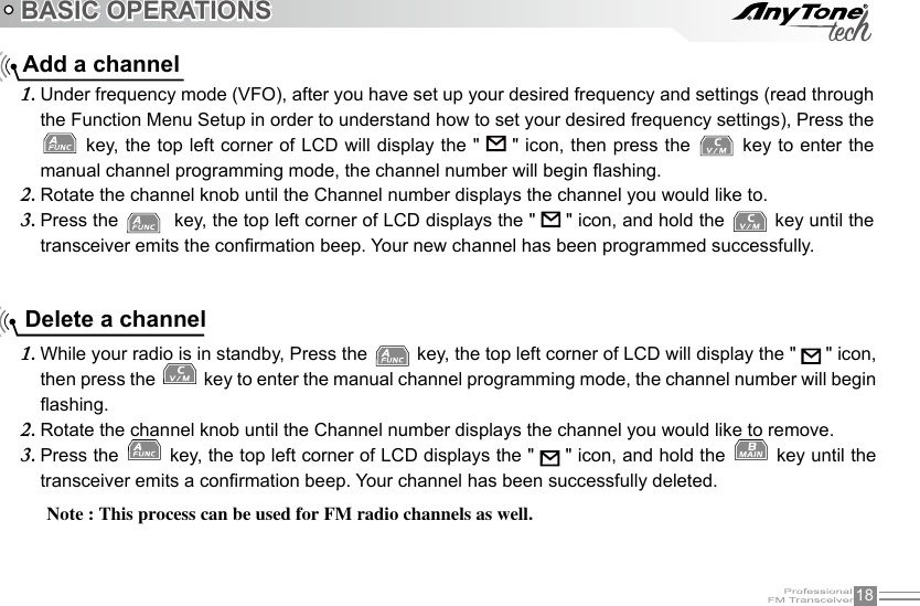
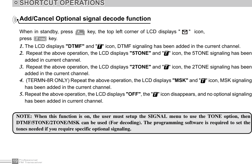
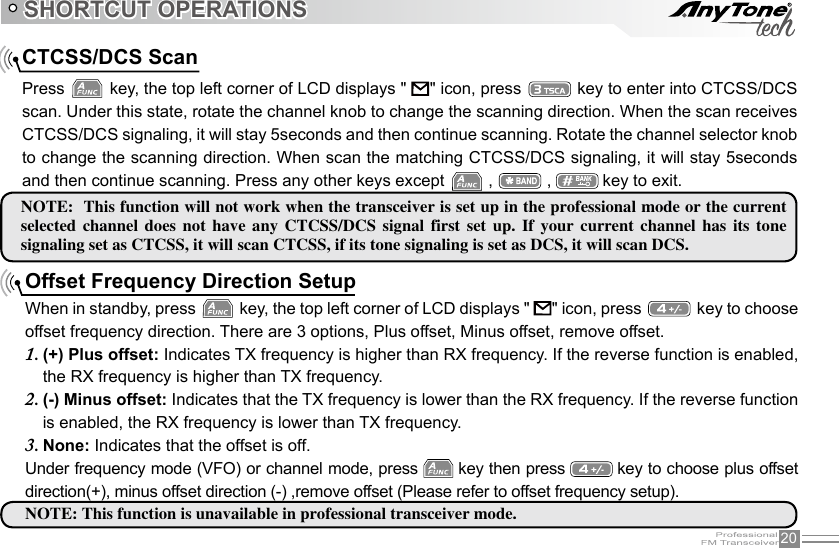
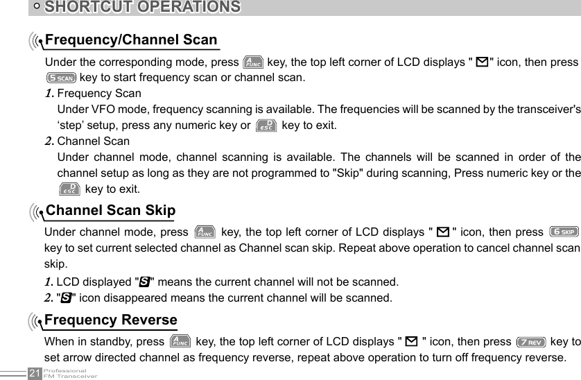
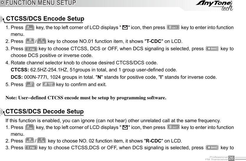
![IITABLE OF CONTENTSReceiving ...................................................................................................................................................................................................14Transmitting .............................................................................................................................................................................................. 15Emergency Alarm .................................................................................................................................................................................. 15Side Key [PF1] Setup and Use .......................................................................................................................................................15Side Key [PF2] Setup and Use .......................................................................................................................................................17Add a channel ......................................................................................................................................................................................... 18Delete a channel .................................................................................................................................................................................... 18SHORTCUT OPERATIONS ..................................................................................................................................................................... 19Add/Cancel Optional signal decode function ...........................................................................................................................19CTCSS/DCS Scan ................................................................................................................................................................................ 20Offset Frequency Direction Setup ................................................................................................................................................. 20Frequency/Channel Scan .................................................................................................................................................................. 21Channel Scan Skip ...............................................................................................................................................................................21Frequency Reverse .............................................................................................................................................................................. 21TX Power selection ...............................................................................................................................................................................22Talk Around function ............................................................................................................................................................................. 22DTMF code Transmit and Enquiry ................................................................................................................................................ 22Keypad lock .............................................................................................................................................................................................. 23Single-band Switching ......................................................................................................................................................................... 24CTCSS/DCS Encode and Decode................................................................................................................................................ 24MSK (Text) Signal Sending (TERMN-8R ONLY) ................................................................................................................... 25Function Menu Setup ................................................................................................................................................................................ 26CTCSS/DCS Encode Setup ............................................................................................................................................................. 26CTCSS/DCS Decode Setup ............................................................................................................................................................. 26CTCSS/DCS Encode/Decode Synchronous Setup .............................................................................................................. 275TONE encode group selection ..................................................................................................................................................... 28](https://usermanual.wiki/Qixiang-Electron-Science-and-Technology/8RSERIES/User-Guide-2851242-Page-8.png)

![12 Turn the Radio On & OFFNOTE: Press the side key programmed as Squelch Off to monitor the background noise. You can turn the [POWER]/[VOLUME] knob to control the volume. NOTE:INDIVIDUAL CHANNEL SQUELCH LEVEL: While holding the Key Set as 'SQELCH OFF', turn the [Selector Knob] to adjust squelch level for current channel (this will set the squelch level on the individual channel). Turn [Selector Knob] to adjust squelch level for current channel.BASIC OPERATIONSWhen the radio is off turn [POWER]/ [VOLUME] clockwise to turn on the transceiver.When the radio is on,turn [POWER]/ [VOLUME] counterclockwise to turn off the transceiver.When the radio is on, turn [POWER] / [VOLUME] to adjust volume. The volume increases when you turn the knob clockwise and decreases when you turn the knob counterclockwise.Adjusting Volume](https://usermanual.wiki/Qixiang-Electron-Science-and-Technology/8RSERIES/User-Guide-2851242-Page-22.png)
![14Frequency AdjustingWhen the transceiver is in VFO frequency mode rotate the channel knob to adjust the frequency, or you can input the frequency by the keypad.Rotate the channel knob clockwise to increase the frequency, rotate it counterclockwise to decrease the frequency. The frequency amount changed depends on the chosen frequency step. It will add or reduce the frequency by the chosen step value.VFO mode: if you want input frequency 151.820MHz, please press [1], [5], [1], [8], [2], [0] on the keypad.BASIC OPERATIONSEnter the desired frequency by increments.1. Enter the desired frequency by keypad.2. ReceivingWhen your transceiver receives a transmission, the LED light will light up (it will light green if the main band is receiving and will light blue if the sub band is receiving) and the arrow icon will ash, and if the volume is up high enough you will also hear the transmission.NOTE: You may not receive the call if your transceiver is set at a high squelch level. If the current channel is programmed with a mandatory decode (RX) tone (CTCSS, DCS, etc), the selected tone also must be presentfor the call to be heard.](https://usermanual.wiki/Qixiang-Electron-Science-and-Technology/8RSERIES/User-Guide-2851242-Page-24.png)
![15BASIC OPERATIONSTransmittingAccording to how the [PF1] or the [PF2] key is setup in the programming software, hold the key programmed as Sqelch Off to monitor the channel to ensure it is not in use, Then press the [PTT] key and talk into the microphone. Keep the distance between your mouth and the microphone about 1-2 inches. Speak in your normal voice (don't whisper and don't yell into the mic) for the best audio clarity.NOTE: When pressing and holding the PTT key, the radio will transmit (and will be indicated by the red LED light). Release the [PTT] key to receive calls.Emergency AlarmWhen the transceiver is in standby, press and hold the [ALARM] key until the LCD displays "ALARM". The emergency alarm has now started. This transceiver has 4 Alarm modes. You can set up which mode works best for you in the programming software. Power off the transceiver to exit Alarm. Side Key [PF1] Setup and Use[PF1] key can be customized to suit your needs, the available options are below:](https://usermanual.wiki/Qixiang-Electron-Science-and-Technology/8RSERIES/User-Guide-2851242-Page-25.png)
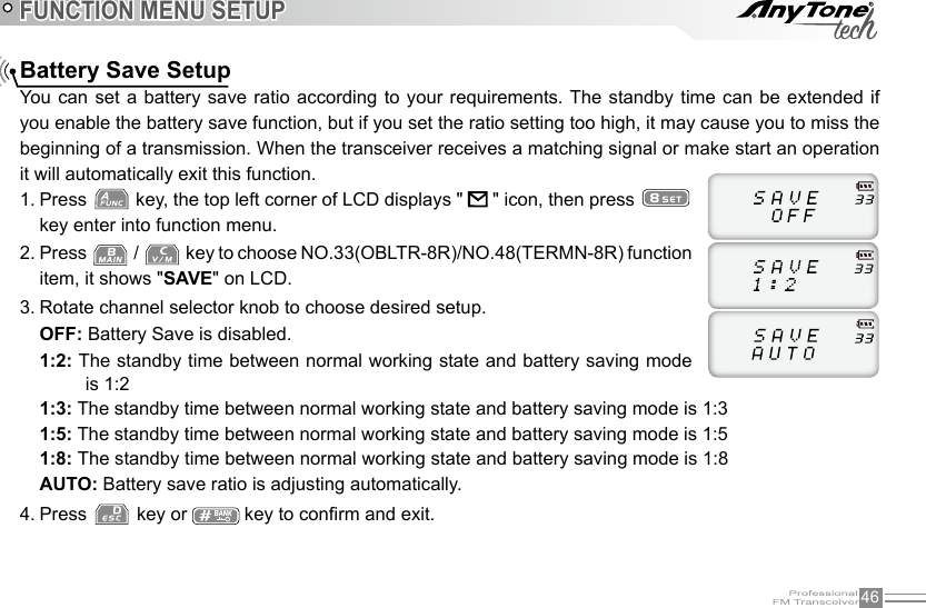
![16BASIC OPERATIONSVOLT:1. Battery capacity inquiry: Under standby, press [PF1] key, LCD displays current battery capacity, press this key again to exit.CALL:2. Transmit the prestored DTMF/5TONE/2TONE/MSK Encode signal in channel.FHSS (TERMN-8R Only): 3. Frequency hopping function. Press the [PF1] key to activate the frequency hopping function,The LCD display will "FHSS", and the transceiver will communicate on the frequency in the pre-set hopping frequency range (set by software).NOTE: The Receiver and the Sender must have the same hopping frequency, and must setup the MSK decode signaling. Using FHSS may cause interference to sub band receive depending on frequency or setting of Menu 51 (sub-band mute).ALARM:4. Activated by a long press of the [PF1]/[PF2] key. The LCD will display "ALARM" and the transceiver will enable the preset alarm function.SUBPTT: 5. Press [PF1]key, transceiver will transmit on the sub-band frequency (use this function to enable "Dual PTT").MONI:6. SDepending how you set up the programming software this will activate 'Squelch off' or 'Squelch off Momentary'. Press the [PF1] key, which will open the squelch, you will hear any noise on the frequency. (If you have it set to 'Squelch off' you must press the [PF1]key again to re-enable the squelch - if you have it set to 'Squelch off Momentary' the squelch will only be open as long as you have the [PF1] key pressed).Transmit tone pulse frequency: 7. Press and hold [PTT] key, then press [PF1] key to transmit selected tone pulse frequency. NOTE: The tone pulse frequency can be set to 1750Hz, 1450Hz, 1000Hz or 2100Hz .Clone Mode: 8. Press and hold the [PF1] key as you turn on the transceiver, to begin and activate the cloning function (see the 'Cloning Cable' Section in this manual for more details)`](https://usermanual.wiki/Qixiang-Electron-Science-and-Technology/8RSERIES/User-Guide-2851242-Page-26.png)
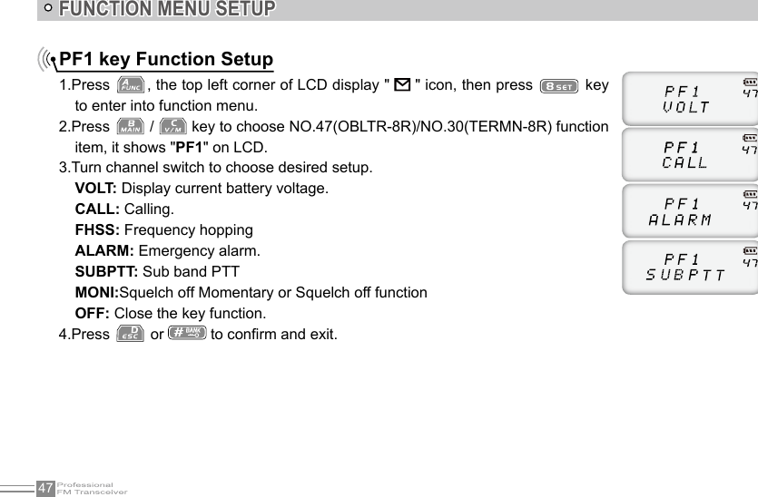
![17 Side Key [PF2] Setup and UseBASIC OPERATIONSThe [PF2] key can be customized to suit your needs, the available options are below:VOLT:1. Battery capacity inquiry: Under standby, press [PF2] key, LCD displays current battery capacity, press this key again to exit.CALL:2. Transmit the prestored DTMF/5TONE/2TONE/MSK Encode signal in channel.FHSS (TERMN-8R Only): 3. Frequency hopping function. Press the [PF2] key to activate the frequency hopping function,The LCD display will "FHSS", and the transceiver will communicate on the frequency in the pre-set hopping frequency range (set by software).Note : The Receiver and the Sender must have the same hopping frequency, and must setup the MSK decode signaling. Using FHSS may cause interference to sub band receive depending on frequency or setting of Menu 51 (sub-band mute).ALARM:4. Activated by a long press of the [PF1]/[PF2] key. The LCD will display "ALARM" and the transceiver will enable the preset alarm function.SUBPTT: 5. Press [PF2] key, transceiver will transmit on the sub-band frequency (use this function to enable "Dual PTT").MONI:6. Depending how you set up the programming software this will activate 'Squelch off' or 'Squelch off Momentary'. Press the [PF2] key, which will open the squelch, you will hear any noise on the frequency. (If you have it set to 'Squelch off' you must press the [PF2]key again to re-enable the squelch - if you have it set to 'Squelch off Momentary' the squelch will only be open as long as you have the [PF2] key pressed).General Function Setup: 7. Press and hold the [PF2] key as you turn on the transceiver, to enter the general function setup (see the 'Display Mode Setup' or the 'PART 95' Sections in this manual for more details).](https://usermanual.wiki/Qixiang-Electron-Science-and-Technology/8RSERIES/User-Guide-2851242-Page-27.png)
![23SHORTCUT OPERATIONSKeypad lockKeypad lock operation can be done by software programming or radio keypad.1) Radio keypad operationRotate channel selector knob to choose desired group and DTMF data, press 2. [PTT] key to transmit selected DTMF signaling. If the current group has no entered DTMF data, the LCD will display the current group number and "EMPTY".When the current group displays 3. "EMPTY", Press key, the top left corner of the LCD will display " " icon, then press and hold 0 key until you hear a responsive beep to get the transceiver to enter into the DTMF edit state. The LCD now displays "___________", now you can enter desired DTMF data by keypad.When nished editing, press side key [PF2] to save DTMF signaling.4. NOTE: When keypad lock is turned on by software programming the keypad lock operation is invalid. Press key, the top left corner of LCD displays " " icon, then press and hold key until you hear a responsive beep and the LCD displays " " icon. This means the keypad is now locked. Repeat the above procedure and the " " icon will disappears. The keypad lock function is now off and the keypad is responsive again.2) Software ProgrammingON: Keypad lock option tick on.OFF: Keypad lock option tick off.](https://usermanual.wiki/Qixiang-Electron-Science-and-Technology/8RSERIES/User-Guide-2851242-Page-33.png)
![24SHORTCUT OPERATIONS Single-band SwitchingTo avoid interference from the sub channels when the main channel is in use, you can use the single band function to turn off the sub channel band quickly.Continuous pressing of will cycle LCD display to show Main + Sub-Band / Sub-Band Only / Main-Band Only. CTCSS/DCS Encode and decode Press 1. key then press [PF2] to enter into setup.Press [PF2] key to choose CTCSS, DCS or OFF, if you choose DCS, press 2. key to select positive or negative code.Rotate the channel knob to choose your desired CTCSS/DCS encode and decode.3. Press 4. key or key to conrm and exit.](https://usermanual.wiki/Qixiang-Electron-Science-and-Technology/8RSERIES/User-Guide-2851242-Page-34.png)
![25SHORTCUT OPERATIONS MSK (Text) Signal Sending (TERMN-8R ONLY)When in standby, press 1. key then press [PF1] key to enter the MSK signal edit function, the LCD will display "_MSG_".Turn the channel knob to choose the desired alpha numeric character.2. Press [PF1] to go to the next character input. Press [PF2] key to go back to the previous character 3. input. You can press the numeric keys to quickly input 0-9, and the next character will automatically be chosen.Once you have chosen your message, press 4. key, the LCD will display "CAL ID" which will allow you to input the receiver's ID then press key or [PTT] key to send your message.Alternatively after you have composed your message, press the 5. key, and the LCD will display "CAL ID" then press / key and you can choose: Call All "CA AL" or Group Calling " CAL GR" (which you will need to input the group ID) and then press key or [PTT] key to send.NOTE:Please refer to the MSK ENCODE/DECODE Setup Options to learn more about the basic setup - found in the ADVANCED FUNCTION OPERATIONS.](https://usermanual.wiki/Qixiang-Electron-Science-and-Technology/8RSERIES/User-Guide-2851242-Page-35.png)
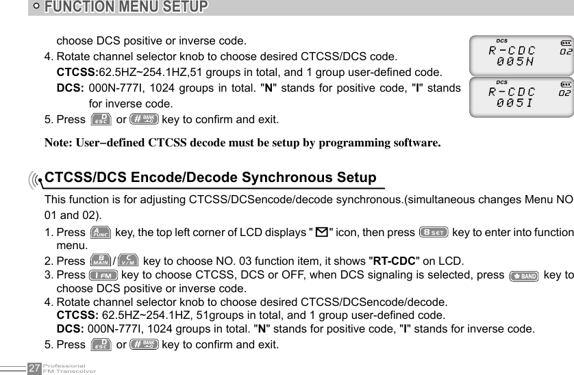
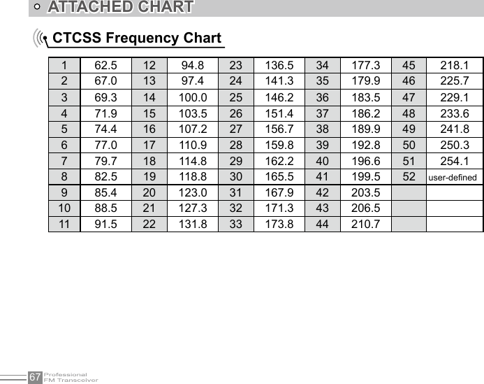
![28Note: User-defined CTCSS decode must be setup by programming software.FUNCTION MENU SETUP5TONE encode must be programmed by software, only the groups that have edited 5TONE can be selected. When 5TONE encode has a name, transceiver will display name, otherwise will display "CALL XX". 5TONE encode group selection1. Press key, the top left corner of LCD displays " " icon, then press key to enter into function menu.2. Press / key to choose NO.04(OBLTR-8R)/NO.05(TERMN-8R) function item, it shows "5T-ENC" on LCD.3. Rotate channel selector knob to choose desired 5TONE encode group.CALL00~CALL99, 100 groups in total for optional.4. Press [PTT] key to transmit selected 5TONE encode, press key or key to conrm and exit.2TONE encode group selection1. Press key, the top left corner of LCD displays " " icon, then press key to enter into function menu.](https://usermanual.wiki/Qixiang-Electron-Science-and-Technology/8RSERIES/User-Guide-2851242-Page-38.png)
![29FUNCTION MENU SETUP2TONE encode must be programmed by software, only the groups that have edited 2TONE can be selected. When 2TONE encode has a name, transceiver will display name, otherwise will display "CALL XX". Optional signaling setupDTMF, 2TONE (Paging), 5TONE, MSK (TERMN-8R Only) functions are similar to CTCSS/DCS, it has special call functions, such as ANI, PTT ID, All call, Alarm, remotely kill, remotely stun and remotely waken, etc. (MSK gives the capabilities of Message sending and FHSS - TERMN-8R Only) .1. Press key, the top left corner of LCD displays " " icon, then press key to enter into function menu.2. Press / key to choose NO.06(OBLTR-8R)/NO.08(TERMN-8R) function item, it shows "TONDEC" on LCD.3. Rotate channel selector knob to choose desired optional signaling.2. Press / key to choose NO.05(OBLTR-8R)/NO.04(TERMN-8R) function item, it shows "2T-ENC" on LCD.3. Rotate channel selector knob to choose desired 2TONE encode group.4. Press [PTT] key to transmit selected 2TONE encode, press key or key to conrm and exit.](https://usermanual.wiki/Qixiang-Electron-Science-and-Technology/8RSERIES/User-Guide-2851242-Page-39.png)
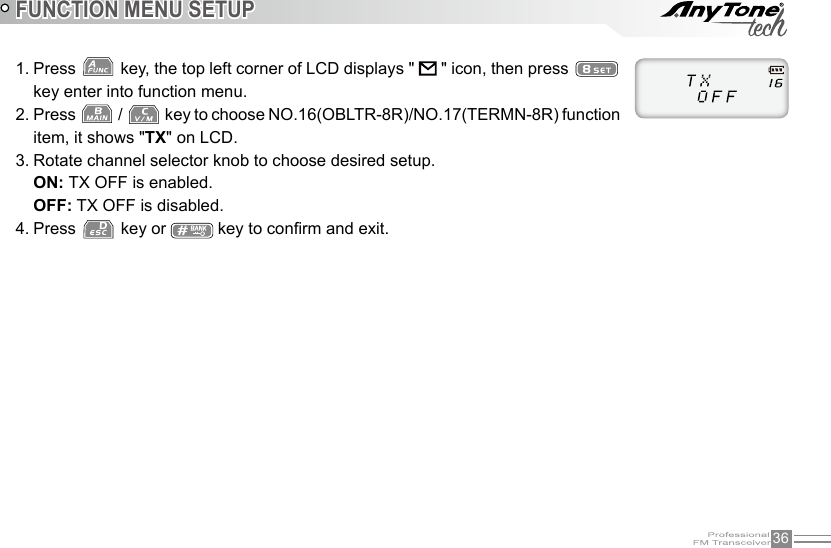
![35FUNCTION MENU SETUPBusy Channel LockoutBCLO function is used to prohibit transmitting on a busy channel, it can prevent disturbing other transceivers operating on the same frequency. If you press PTT, the radio will beep as warning and go back to a receiving state.1. Press key, the top left corner of LCD displays " " icon, then press key enter into function menu.2. Press / key to choose NO.15(OBLTR-8R)/NO.16(TERMN-8R) function item, it shows "RPLOCK" on LCD.3. Rotate channel selector knob to choose desired setup.BUSY: Carrier wave lock, transmitting is prohibited when received matching frequency and tone wave.REPEAT: Signal lock, transmitting is prohibited when received matching carrier (frequency) (CTCSS and DCS tones are ignored in this setting).OFF: No BCLO function.4. Press key or key to conrm and exit.TX OFFWhen this function is on, the [PTT] key is not allowed on the current channel. Current channel of transceiver only works as a receiver and not a transmitter.](https://usermanual.wiki/Qixiang-Electron-Science-and-Technology/8RSERIES/User-Guide-2851242-Page-45.png)
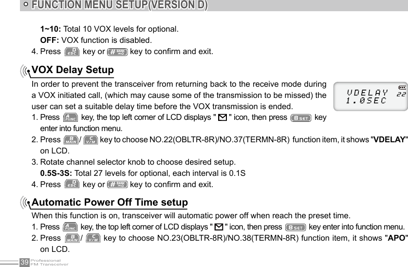
![38FUNCTION MENU SETUPTime-Out-Timer (TOT)The purpose of Time-out-Timer is to restrict the transceiver from accidental long-term transmissions. If the transmission time goes beyond the preset time limit, the transceiver is forced to stop transmitting and warn the user and make a beep sound.1. Press key, the top left corner of LCD displays " " icon, then press key enter into function menu.2. Press / key to choose NO.20(OBLTR-8R)/NO.35(TERMN-8R) function item, it shows "TOT" on LCD.3. Rotate channel selector knob to choose desired setup.OBLTR-8R: 1~27 minutes, total 27minutes of TOT for optional, each interval is 1minute.TERMN-8R:10-270S,total 27 levels for options each level step 10seconds.4. Press key or key to conrm and exit.Voice Operated Transmission (VOX) SetupWhen this function is enabled, the transmitting can be started by your voice (generally used with an earpiece), When it is enabled there is no need to press the [PTT] key.1. Press key, the top left corner of LCD displays " " icon, then press key enter into function menu.2. Press / key to choose NO.21(OBLTR-8R)/NO.36(TERMN-8R) function item, it shows "VOX" on LCD.3. Rotate channel selector knob to choose desired setup.](https://usermanual.wiki/Qixiang-Electron-Science-and-Technology/8RSERIES/User-Guide-2851242-Page-48.png)
![49ADVANCED FUNCTION OPERATIONSDisplay Mode SetupThere are three kinds of display (user) modes.Press [PF2] key as you turn on the radio, continue holding the [PF2] key until the 1. transceiver emits a beep.Press 2. / key to choose No.01 function item, it shows "DSP" on LCD.Rotate channel switch to choose desired setup.3. FREQ: Frequency+Channel mode, transceiver displays current channel number + frequency, press key to switch into VFO mode.CH: Channel mode (for commercial use), 1~24 items of function menu will be disabled, the user can only operate some functions. The VFO Mode is disabled. With this mode, radio can be used as commercial radio.NAME: Channel+Name Tag mode, transceiver displays current channel number +channel name, press key to switch into VFO mode.Press 4. key or key to conrm and exit.Resume Factory DefaultYou can make all the settings of transceiver return back to the factory default settings when the transceiver does not work normally (possible due to bad settings)](https://usermanual.wiki/Qixiang-Electron-Science-and-Technology/8RSERIES/User-Guide-2851242-Page-59.png)
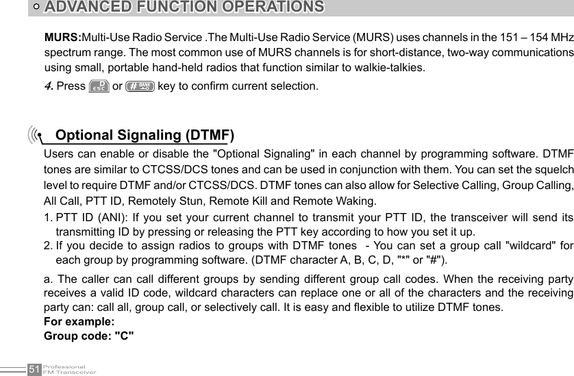
![50ADVANCED FUNCTION OPERATIONSThere are three kinds of modes for optional. NORMAL ,and MURS.NORMAL:Normal channel modePress [PF2] key as you turn on the radio, continue holding the [PF2] key until the transceiver emits a 1. beep.Press 2. / key to choose No.03 function items, it shows "PART95" on LCD.Rotate channel switch to choose desired setup3. Public Usage Frequency Mode (FCC Part 95)Press [PF2] key to turn on radio, hold [PF2] key until transceiver emits beep.1. Press 2. / key to choose No.02 function item, it shows "RESTOR" on LCD.Rotate channel switch to choose desired setup.3. OFF: No operations.FACT: Resume all items to factory default, including channel and background settings.INIT: Resume background settings to factory default, channel operations are keeping.Press 4. key to exit current selection.Press 5. key to conrm current selection.](https://usermanual.wiki/Qixiang-Electron-Science-and-Technology/8RSERIES/User-Guide-2851242-Page-60.png)
![53ADVANCED FUNCTION OPERATIONS2TONE CallingTwo-tone sequential, also known as 1+1, is a selective calling method (2 Tones received to set off the pager function). Many companies have their own names for two-tone sequential options.General Electric Mobile Radio ® called it Type 99. Motorola ® called it Quik-Call II. For example, the encoder sends a single tone followed by 50 to 1,000 milliseconds of silence and then a second tone.[3] Decoders look for a valid rst tone followed by a valid second tone. If no valid second tone is decoded within 2 seconds, the decoder resets and waits for another valid rst tone.To set up the 2TONE needed to encode (send) or decode (receive) you need to set it up through programming software. You can set up to 32 Encode options and 16 Decode. NOTE:To set your radio to open for calls only after receiving a 2TONE sequence - set up the channel decode option as needed - and then apply it to the frequency needed. YOU WILL NEED TO SET THE SQUELCH MODE AS"OPTIONAL SIGNALING"to receive the call. Refer to"Function Menu Setup - Squelch mode setup"for more details.NOTE:Radios must be set up to 'Decode' optional signaling (2TONE), otherwise they will ignore the 2TONE tones being received.](https://usermanual.wiki/Qixiang-Electron-Science-and-Technology/8RSERIES/User-Guide-2851242-Page-63.png)
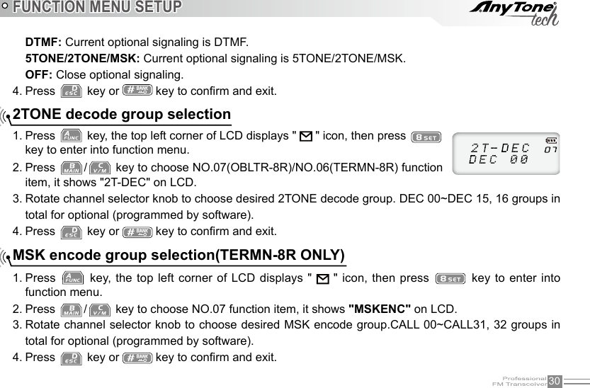
![59ADVANCED FUNCTION OPERATIONSCloning CableThis feature will copy the programmed data and parameters from the master unit to slave units. It copies the parameters and memory program settings.Connection: Use optional CP04 cloning cable, connect Read/write frequency port on both master and slave, setting and programing as the requirement below.BANKBANKBANDBAND[Settings: Master side]Press the [PF1] side key to Power on, the display shows "CLONE", the master unit enters into copy 1. mode . Press [PF1] key, the display appears "CLONE XX" XX stands for the data amount 2. being cloned. When the data transfer is completed, slave unit restarts, the master unit displays 3. "CLONE 04".Master unit will remain in the cloning mode to prepare for the next cloning session, 4. if you reboot the master radio - it will exit the cloning mode and return back to the normal mode.](https://usermanual.wiki/Qixiang-Electron-Science-and-Technology/8RSERIES/User-Guide-2851242-Page-69.png)
![60ADVANCED FUNCTION OPERATIONS[Settings: Slave side]In the standby mode, when the slave receives the data, the display shows "CLONE XX" XX stands for 1. the data being cloned.When data reception is complete, the slave unit returns to normal mode and 2. restarts automatically.Turn off the slave's power, remove the cable, insert another slave that you want 3. to copy.If the data is not successfully transmitted, turn off the master and slave, check if the cable connections are correct, and then repeat the whole process again.](https://usermanual.wiki/Qixiang-Electron-Science-and-Technology/8RSERIES/User-Guide-2851242-Page-70.png)
![66TROUBLE SHOOTING GUIDECan not power on or frequent power off Check if the battery is making good contact and is locked in place.The transmitting audio gets low or intermittentCheck if the MIC hole is plugged. If you cannot diagnose the issue -contact local dealer for repair. Receiving is intermittent with too much noiseA. Out of communication range or obstructed by tall buildings.B. The 450 filter is broken, Contact local dealer for repair.Loudspeaker is quieter or has crackling soundCheck whether the loudspeaker is broken, or if there is powder or dust in the loudspeaker. Contact local dealer for repair.Receive voice from the other party but can not transmit Check [PTT] key.Receiving indicator with green light but no soundA. Low volume, please turn the VOLUME knob clockwise.B.Loudspeaker is broken, Contact local dealer for repair.C.Earphone jack is broken, Contact local dealer for repairD.Volume switch is broken.](https://usermanual.wiki/Qixiang-Electron-Science-and-Technology/8RSERIES/User-Guide-2851242-Page-76.png)