Qixiang Electron Science and Technology D878UV Digital DMR and analog UHF/VHF Two Way Radio User Manual
Qixiang Electron Science& Technology Co., Ltd Digital DMR and analog UHF/VHF Two Way Radio
user manual

A2.180930
www.anytone.net
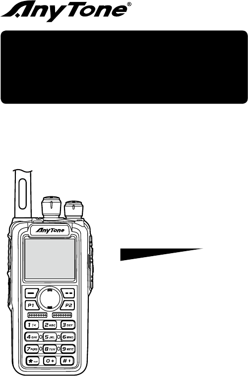
AT-D878UV
Operating Manual
Digital DMR and Analog
UHF/VHF Two Way Radio
DMR
DIGITAL MOBILE RADIO ASSOCIATION

THANK YOU!
Thank you very much for choosing our Dual Band Digital DMR
and Analog two way radio.
This radio adopts the latest advances in technology, providing reliable
communication in today’s demanding communication environment.
This radio offers both DMR digital and analog communication, introduces
innovative DMR digital processing system to achieve SMS, high-audio
quality and digital encryption. It offers great stability, and reliability, together
with long distance communication as well as fashionable design and
compact exterior lines. AT-D878UV has Text Messaging, Recording, Voice
Message, Digital Encryption, Emergency Alarm, Man Down Alarm, Work
Alone GPS, APRS Location Reporting, Roaming, Vibration, Analog DTMF,
2TONE, 5TONE, CTCSS/DCS encode/decode functions.
CONTENTS
1.UNPACKING AND CHECKING THE EQUIPMENT ........................ 1
1.1 Supplied Accessories ................................................................. 1
1.2 Standard Accessories ................................................................ 2
1.3 Optional Accessories ................................................................. 2
2.BATTERY INFORMATION .............................................................. 3
2.1 Charging the Battery Pack ......................................................... 3
2.2 Charger Supplied ....................................................................... 3
2.3 Use Caution with the Li-ion Battery ............................................ 3
2.4 How to Charge ........................................................................... 4
2.5 Normal Charging Tips ................................................................ 5
2.6 How to Store the Battery ............................................................ 6
3. PREPARATION .............................................................................. 7
3.1 Installing / Removing the Battery ............................................... 7
3.2 Installing / Removing the Antenna ............................................. 7
3.3 Installing / Removing the Belt Clip ............................................. 8
3.4 Installing the Additional Speaker/Microphone (Optional) ........... 8
4. Radio Overview............................................................................. 9
4.1 Status Indications ..................................................................... 10
4.2 Programmed Key ..................................................................... 10
4.3 Hot Key Setting for PF1, PF2, PF3, P1, P2 ............................. 12
4.4 Combination key function ......................................................... 12
5.BASIC OPERATIONS ................................................................... 13
5.1 Power on the Radio ................................................................. 13
5.2 Adjust Volume .......................................................................... 13
5.3 Main band/Sub band switch ..................................................... 13
5.4 VFO/Channel switch ................................................................ 13
5.5 Set up VFO frequency ............................................................. 13
5.6 Select a Channel ...................................................................... 13
5.7 New channel ............................................................................ 14
5.8 Delete Channel ........................................................................ 14
5.9 Receiving and Responding to a Radio Call ............................. 14
5.10 Making a Call ......................................................................... 15
5.11 Monitor ................................................................................... 15
5.12 Emergency Alarm ................................................................... 15
5.13 Man Down Alarm .................................................................... 15
5.14 Battery Voltage Test ............................................................... 16
6. ADVANCED FEATURES ............................................................. 17
6.1 Access Advanced Features for Private Call ............................. 17
6.2 Set up Advanced Features for Private Call .............................. 17
7.MAIN MENU FUNCTIONS ............................................................ 19
7.1 Talk Group ................................................................................ 19
7.2 SMS ......................................................................................... 19
7.3 Call Log .................................................................................... 19
7.4 Zone ......................................................................................... 19
7.5 Scan ......................................................................................... 20
7.6 Roaming ................................................................................... 21
7.7 Settings .................................................................................... 22
7.7.1 Radio Set ................................................................................... 22
7.7.2 Chan Set.................................................................................... 26
7.7.3 Device Info................................................................................. 31
7.8 Record ..................................................................................... 31
7.9 GPS Positioning Function(Optional with installed GPS) .......... 32
7.10 APRS Location Reporting(Supported by GPS) ...................... 33
7.11 Digital Monitor ........................................................................ 34
7.12 Bluetooth function (Optional with installed Bluetooth) ............ 35
8.RESET........................................................................................... 36
9.TROUBLE SHOOTING GUIDE ..................................................... 37
10.PROGRAMMING GUIDE ............................................................ 38
11.ON-LINE SERVICE AND SUPPORT .......................................... 40
SAFETY ........................................................................................... 41
EU DECLARATION OF CONFORMITY .......................................... 43
12.TECHNICAL SPECIFICATIONS ................................................. 44
1AT-D878UV Digital DMR and Analog UHF/VHF Two Way Radio
1. UNPACKING AND CHECKING THE EQUIPMENT
Unpack the radio carefully. We recommend that you identify the items listed
in the following table before discarding the packing materials. If any items
are missing or have been damaged during shipment, please contact the
carrier or the dealers immediately.
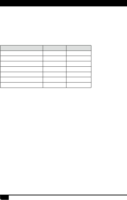
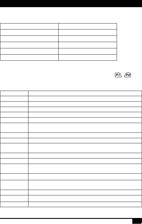
1.1 Supplied Accessories
Item Number Quantity
Antenna 1
Li-ion Battery Pack 1
Battery Charger 1
AC Adaptor 1
Belt Clip 1
Hand Strap 1
Instruction Manual 1
1. Unpacking and Checking the Equipment
2
AT-D878UV Digital DMR and Analog UHF/VHF Two Way Radio
1. Unpacking and Checking the Equipment
1. UNPACKING AND CHECKING THE EQUIPMENT
1.2 Standard Accessories
Antenna*1
QA-11UV
Li-ion Battery Pack
QB-44HL(3100mAh)
Charger
QBC-45L
AC Adaptor
QPS-17
Belt Clip
BC-05
Wrist strap Instruction Manual
* Note: For frequency band of antenna, please refer to label indicated in
the bottom of the antenna.
* Note: Car Charger and QBC-45L Charger should be used together.
Li-ion Battery Pack
QB-44HL(3100mAh)
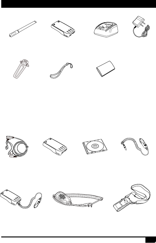
1.3 Optional Accessories
Programming
Software
Earphone
EJX-023
Car Charger
CPL-01
Battery Eliminator
CPL-02
Speaker Microphone
QHM-024
Leather Case
PT-878

3AT-D878UV Digital DMR and Analog UHF/VHF Two Way Radio
2.2 Charger Supplied
2.3 Use Caution with the Li-ion Battery
The Li-ion battery pack is not charged at the factory; please charge it
before use.
Charging the battery pack for the first time after purchase or extended
storage (more than 2 months) may not bring the battery pack to its normal
maximum operating capacity. Best operation will require fully charging/
discharging the battery two or three times before the operating capacity will
reach its best performance. The battery pack life may be depleted when
its operating time decreases even though it has been fully and correctly
charged. If this is the case, replace the battery pack.
Please use the specied charger provided by AnyTone. Other models may
cause explosion and personal injury. After installing the battery pack, and
if the radio displays low battery with a red ashing lamp or voice prompt,
please charge the battery.
a. Do not short the battery terminals or throw the battery into a re. Never
attempt to remove the casing from the battery pack, as AnyTone cannot
be held responsible for any accident caused by modifying the battery.
b. The ambient temperature should be between 5℃-40℃ (40˚F - 105˚F)
while charging the battery. Charging outside this range may not fully
charge the battery.
c. Please turn off the radio before inserting it into the charger. It may
otherwise interfere with correct charging.
d. To avoid interfering with the charging cycle, please do not cut off the
power or remove the battery during charging until the green light is on.
e. Do not recharge the battery pack if it is fully charged. This may shorten
the life of the battery pack or damage the battery pack.
f. Do not charge the battery or the radio if it is damp. Dry it before charging
to avoid damage.
2.1 Charging the Battery Pack
2. BATTERY INFORMATION
4
AT-D878UV Digital DMR and Analog UHF/VHF Two Way Radio
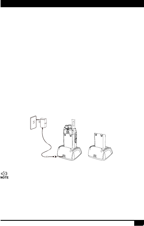
2.4 How to Charge
WARNING:
»When keys, ornamental chain or other electric metals contact the
battery terminal, the battery may become damage or injure a human.
If the battery terminals are short circuited it will generate a lot of heat.
Take care when carrying and using the battery. Remember to put the
battery or radio into an insulated container. Do not put it into a metal
container.
a. Plug the AC adaptor into the AC outlet, and then plug the cable of the
AC adaptor into the DC jack located on the back of the charger. The
indicator light blinks orange and is then ready to charge a battery.
b. Plug the battery or the radio into the charger. Make sure the battery
terminals are good in contact with charging terminals. The indicator light
turns to red--- charging begins.
c. It takes approximately 2-5 hours to fully charge the battery. When the
lamp lights green, the charging is completed. Remove the battery or the
radio unit with its battery from socket
»when charging a radio (with battery) the indicating lamp will
not turn into green to show the fully charged status if the radio
is powered on. Only when the radio is switched off will the lamp
indicate normal operation. The radio consumes energy when it
is power-on, and the charger cannot detect the correct battery
voltage when the battery has been fully charged. So the charger
will charge the battery in constant voltage mode and fail to
indicate correctly when the battery has been fully charged.
2. BATTERY INFORMATION
5AT-D878UV Digital DMR and Analog UHF/VHF Two Way Radio
STATUS LED
Self-Test When Power on Red (for 1 second)
No Battery Green
Charge Normally Red
Fully Charged Green
Trouble Red blinks fast for a long time
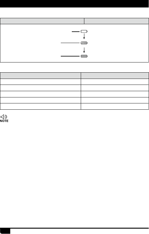
f. LED Indicator:
Charging Status Indicator Status
Standby (Self-examine lights red
1second when power on) None
Charging
(Charge in a constant current) Lights red for about 3 hours
Fully charged
(Charge in a constant voltage) Lights green
»Trouble means battery too warm, battery short-circuited or
charger short-circuited.
2.5 Normal Charging Tips
a. Self-Test: When powering on the charger, the red light turns on and then
turns off and stays off, which means the charger has passed it self- test
and it is ready to charge the battery. If the light remains orange or the
red light blinks, it means the charger cannot pass it self-test and cannot
charge the battery.
b. Trickle Pre-Charging: If red light blinks when the battery is inserted
into the charger, it means that the battery voltage is low and the charger
is trickle-charging the battery (Pre-Charging Mode). The charger will
automatically turn into normal charging when the battery reaches a
certain electric charge, and if the red light stops blinking, it means the
battery voltage has reached a certain level, and the charger will charge
the battery in normal mode.
e. Charging Process
2. BATTERY INFORMATION

6
AT-D878UV Digital DMR and Analog UHF/VHF Two Way Radio
»Trickle charging (Pre-Charging Mode) time cannot last beyond
30 minutes. If the indicating lamp still blinks red after 30-minute
trickle-charging, it means that the charger cannot charge the
battery correctly. Please check whether the battery or charger is
damaged.
»Do not short circuit the battery terminals.
»Never attempt to remove the casing from the battery pack.
»Never store the battery in unsafe surroundings, as a short may
cause an explosion.
»Do not put the battery in a hot environment or throw it into a re,
as it may cause an explosion.
2.6 How to Store the Battery
a. If the battery needs to be stored, keep it in status of 80% discharged.
b. It should be kept in low temperature and dry environment.
c. Keep it away from hot places and direct sunlight.
2. BATTERY INFORMATION
7AT-D878UV Digital DMR and Analog UHF/VHF Two Way Radio
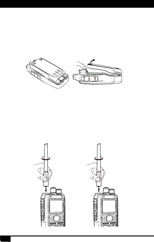
3.2 Installing / Removing the Antenna
a. Installing the Antenna: Screw the antenna into the connector on the
top of the transceiver by holding the antenna at its base and turning it
clockwise until secure.
b. Removing the Antenna: Turn the antenna counter-clockwise to remove
it.
3.1 Installing / Removing the Battery
a. Match the two bottom grooves of the battery pack with the corresponding
guides on the back of the radio and then push it.
b. To remove the battery pack, slide the release latch at the top away from
the battery and remove the pack away from the transceiver.
3. PREPARATION
8
AT-D878UV Digital DMR and Analog UHF/VHF Two Way Radio
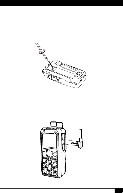
3.4
Installing the Additional Speaker/Microphone (Optional)
Pry open the rubber MIC-Headset jack cover and then insert the Speaker /
Microphone plug into the double jack.
3.3 Installing / Removing the Belt Clip
a. Installing the Belt Clip: Place the belt clip above the corresponding holes
on the back of the radio, and screw it into place clockwise with the two
supplied screws.
b. Removing the Belt Clip: Unscrew counter-clockwise to remove the belt
clip.
3. PREPARATION
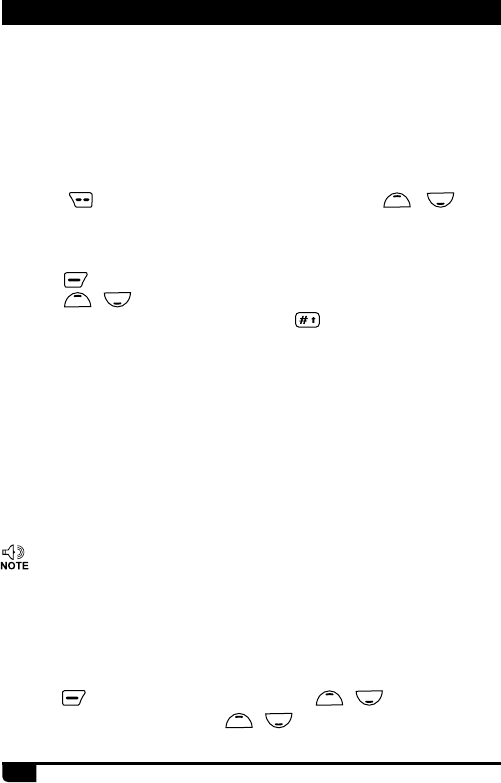
9AT-D878UV Digital DMR and Analog UHF/VHF Two Way Radio
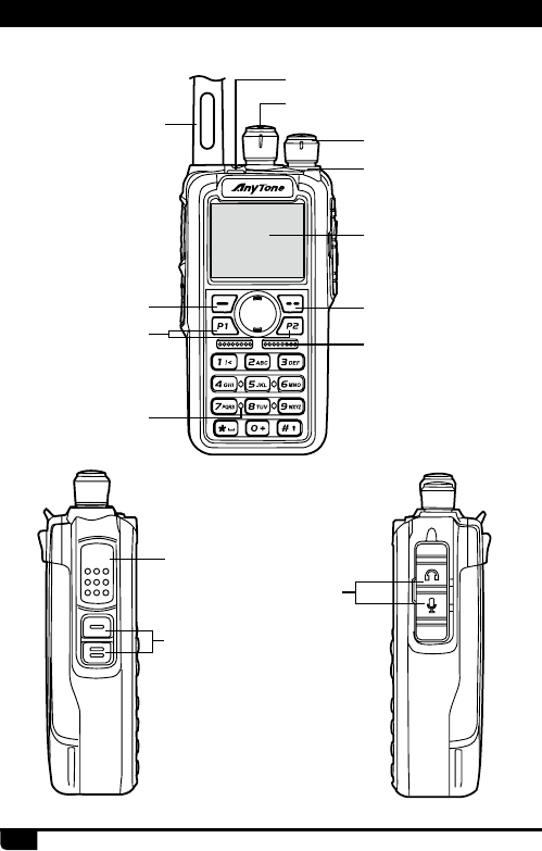
Emergency Alarm Key (PF3)
Antenna
Menu key
P1 key/ P2 key
MIC Input
Speaker/Mic Jacks
Channel Switch
POWER/VOL
LED Status Indicator
LCD
Exit Key
Speaker
PTT Button
[PF1] top Key
[PF2] bottom Key
4. RADIO OVERVIEW
PTT
10
AT-D878UV Digital DMR and Analog UHF/VHF Two Way Radio
4. RADIO OVERVIEW
The top LED will help you to identify the current radio status.
4.1 Status Indications
LED Indication Status
Flashes Red Low battery voltage
Constant Red Transmitting
Constant Green Analog Receiving
Constant Cyan Digital Receiving
Flashes Green Scan
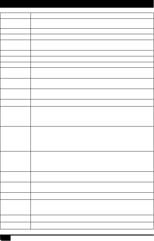
4.2 Programmed Key
It is possible to set different functions for [PF1], [PF2], [PF3], , keys.
Method 1: In radio Menu - Settings - Radio Set - Key - PF1, PF2, PF3, P1,P2.
Method 2: In PC software - Public - Optional Setting - Key function.
OFF No Function
Volt Check the current battery capacity voltage
Tx Power Switch the power between super high, high, middle and low power.
TalkAround Switch between Talk Around and Repeater mode
Reverse Turn on/off the frequency reverse function.
Digi Encrypt Choose the digital encryption group for digital channel
Call In Analog mode, send the DTMF/5TONE/2TONE encode. This
function is only valid for analog channel.
VOX Set up the VOX level
VFO / MR Switch between VFO mode and memory channel mode.
Sub PTT Sub channel PTT, press to start the call on sub channel (NOTE: On
PF1 - PF2 - PF3 Keys Only)
Scan Scan on/off
FM Radio FM radio on/off
Alarm Long press the key to start alarm, short press again to exit the
alarm.
Record Switch Enable/disable the recording function
Record Start/stop recording. When stop recording, the radio will remind
repeat or send the record.
SMS In digital mode, press to enter into SMS messages
Dial Start the manually dial
GPS Info Check the GPS position information
11 AT-D878UV Digital DMR and Analog UHF/VHF Two Way Radio
4. RADIO OVERVIEW
Monitor Monitor the weak signal or the signal with unmatched ID.
Main CH Switch Choose channel A or channel B as the main channel
Hot Key 1~6 Selects Hot Keys 1-6 Note: Hot key setup details on next page
Work Alone Turn on/off the work alone function.
Nuisance
Delete During scanning, press the key to skip the unwanted channel
Digi Monitor In DMR mode, press the key to turn on/off digital monitor
Sub CH Hide Turn on/ off the sub channel
Prior Zone Switch to Priority Zone
Program Scan "Press the key to start the scan in VFO channel scan start and end
frequency must be programmed in CPS."
Enhance Sound In digital channel, switch the microphone tone to normal or
enhanced mode.
LastCall Reply In digital channel, press the key to access the last call and press
PTT to call back.
Switch ChType Switch the channel type(Analog, Digital, Ana+Dgi, Dgi+Ana)
Ranging
When the radio receives a call and the suspension time is on, press
the key programmed as" Ranging" to obtain the caller's position and
distance. (Both party need GPS positioned, or will receive only GPS
information)
Roaming
In standby, press the key programmed as "Roaming" to search and
lock on the repeater with strongest signal. (Note: After lock on a
repeater, the radio will return to last frequency only after channel
or frequency is changed. The repeater frequency list must pre-
programmed in CPS.)
Channel
Ranging
In standby, if the call contact type for a channel is "Single call" ,
press the key programmed as " Channel Ranging" to turn on this
function. The radio will automatically start ranging function when turn
to this channel.
Max VOL Set In standby, press the key programmed as" Max Volume", will enable
users to set the maximum RX volume.
Slot Set Choose Slot for current channel, this function is only valid in repeater
mode.
Aprs Type Choose Aprs Type for current channel.
Zone Select
In standby, press the programmed "Zone Select" key, it will allow
you input the zone number and then press conrm key will switch to
the zone.
Roaming Set Sets Roaming Function
APRS Set Sets APRS Function
12
AT-D878UV Digital DMR and Analog UHF/VHF Two Way Radio
4.3 Hot Key Setting for PF1, PF2, PF3, P1, P2
4.4 Combination Key Function
+ number key operation:
Press key and hold until the LCD display “Next Please Press Dial Key”,
press the number key, it will perform the programmed function.
Combination key function shall be setup in PC software-Public-Hot key.
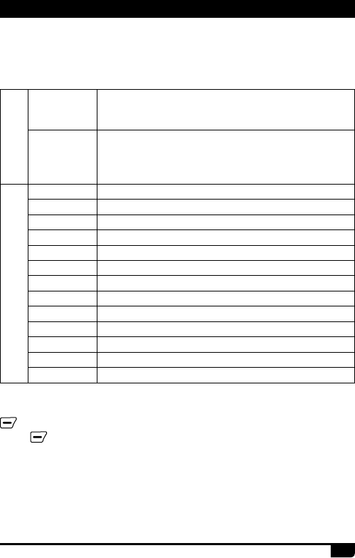
Call
Analog
Should edit the analog quick call rst, then choose analog in
the hot key set. Press the key to transmit 2Tone/5Tone/DTMF
to start the analog quick call.
Digital
It allows to select a contact from the digital contact list, press
the key to switch the channel to the contact temporary. It will
switch back to the original contact after the group/personal
call hold time.
Menu
SMS Quick access to Messages in the menu
New Msg Quick access to New Msg in the Menu - Messages
Hot Text Quick access to Quick Text in the Menu - Messages
Received SMS Quick access to Inbox in the Menu - Messages
Send SMS Quick access to Out box in the Menu - Messages
Contact list Quick access to Contact list in the Menu - Contacts
Manual dial Quick access to Manual Dial in the Menu - Contacts
Call Log Quick access to Call Log in the Menu
Dialed Calls Quick access to Dialed Calls in the Menu - Call Log
Received Calls Quick access to Answered Calls in the Menu - Call Log
Missed Calls Quick access to Missed Calls in the Menu - Call Log
Zone Quick access to Zone in the Menu
Radio set Quick access to Radio Set in the Menu - Settings
4. RADIO OVERVIEW
Enter radio Menu-Settings-Radio Set-PF1, PF2,PF3,P1,P2,sub menu.
Users can choose settings for Hot Keys 1-6.
Hot Key function details must be setup in PC software – Public - Hot key.
13 AT-D878UV Digital DMR and Analog UHF/VHF Two Way Radio
5.1 Power on the Radio
5.2 Adjust Volume
5.3 Main Band/Sub Band Switch
5.4 VFO/Channel Switch
5.5 Set Up VFO Frequency
Turn on the radio by turning the [Power/Volume] switch clockwise till a click
is heard, and the LCD displays will show a start-up message, and you will
hear a beep after 7 seconds.
Rotate the [Power/Volume] knob to adjust the volume. Turn clockwise to
increase the volume and counterclockwise to decrease the volume. The
LCD display will show the volume status during an adjustment.
Press the key to switch the main channel to the other channel
if there is 2 channels shown on the display. The channel with bold
characters is the main channel.
Press the key to switch between VFO and channel display.
Turn the radio to VFO mode , then press the key to switch to the
main band, the VFO frequency can only be set up when the channel is in
the main “bold text” channel.
Operation 1: Input the VFO frequency directly by the keyboard.
Operation 2: Turn the channel selector to adjust the VFO frequency steps.
5. BASIC OPERATIONS
5.6 Select a Channel
Press key to switch the radio between VFO and Channel mode, select
Channel mode.
Operation 1: Turn the channel switch to select a channel.
Operation 2: Input the channel numbers by the keyboard. For example, if
you want switch to channel 99, input 0+0+9+9 a total of 4 digits, and it will
switch to channel 99.
A channel can either be Analog or Digital.
For the analog channels the Push-To-Talk button is always available, and
on the Digital Channels the parameters can be set up by the users / system
operators by individual channel to allow talk permit.
There are four possible settings that can be selected in the CPS channel:
(1) Always Allow: The user can transmit all the time.
(2) Channel Free: The radio can transmit only if the channel is free.

14
AT-D878UV Digital DMR and Analog UHF/VHF Two Way Radio
5. BASIC OPERATIONS
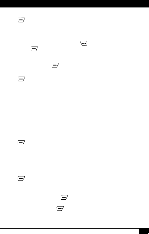
5.7 New channel
5.8 Delete Channel
(1) Press (Menu) to enter main Menu.
(2) Select "Settings".
(3) Select "Chan Set".
(4) Select "New Chan".
(5) Input the channel number by keypad, press to conrm.
(6) Select a zone from zone list, then Conrm To Save. The radio will start
channel saving, and saving is completed when it displays "Saved".
(7) Now select the new channel in the radio and go to Channel Settings
menu to set up all the new channel's parameters.
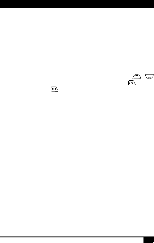
Fast saving a new channel:
Note: Hold (Menu) until displays "Next Please Press Dial Key", then
press [P1] key to start a new channel from above step 5.
(1) In channel (MR) mode, press (Menu) to enter main Menu.
(2) Select "Settings".
(3) Select "Chan Set".
(4) Select "Delete Chan" to delete current channel.
Fast delete a channel:
Note: Hold (Menu) until displays "Next Please Press Dial Key", then
press [P2] key to delete current channel.
5.9 Receiving and Responding to a Radio Call
When the radio is in the digital mode, it can receive and respond to a call
with the same frequency/color code/ slot. When receiving a call:
a. If the radio is programed with callers DMR ID number in the digital
contact list, when receiving a call, the radio will ring or vibrate briey.
b. The blue LED lights up.
c. The left top corner of LCD shows the RSSI icon, and the LCD display
will show DMR ID/name/city/state/country/call type and incoming icon
based on what is in the contact list.
(3) Different Color Code: The radio can transmit if the channel is free, but
the color code is mismatch.
(4) Same Color Code: The radio can transmit only if the channel is free and
the color code matches.
15 AT-D878UV Digital DMR and Analog UHF/VHF Two Way Radio
5. BASIC OPERATIONS
d. When the call is ended, it will display “Call end”, and you can press [PTT]
to respond the call.
5.10 Making a Call
Method 1: from the Channel switch.
Turn the channel switch to choose a programmed channel.
Method 2: from the Talk Group.
(1) Turn the channel switch to choose a programmed channel;
(2) Press (exit) key to enter the TG List, press the / key to
choose a TG.
Method 3: from the keypad.
(1) Turn the channel switch to choose a programmed channel.
(2) Press (Menu) key to Talk Group, press select to enter TG.
(3) Press / key to Manual Dial, press Select.
(4) Input the ID number by keypad, press key to switch group ID or
Private DMR ID.
Hold the radio vertical 2.5-5cm from your mouth, press the [PTT] key to
start the call, the red LED lights up, the receiver ID/name/city/state/country/
call type and call out icon will be display on the LCD.
Release [PTT] key to receive the reply.
»When in analog mode, if no signal, it will emit noise when press the
Monitor Key. ** The Rx icon is seen when monitor is activated.
5.11 Monitor
In standby, press the [PF2] key to enter Monitor. When receiving matched
carrier but the signaling / ID is unmatched or the signal is too weak, this
function allows monitor the weak signal and signal with unmatched ID.
Press the [PF2] key again to shut off speaker and return to standby.
5.12 Emergency Alarm
Press Emergency Alarm key [PF3] to turn alarm function, then press this
key again to return.
a. Press (Menu) to enter main Menu, press / key to Settings.
b. Select Radio Set, press, press / key to Man Down.
c. Select Man Down On to turn on the function.
5.13 Man Down Alarm

16
AT-D878UV Digital DMR and Analog UHF/VHF Two Way Radio
5. BASIC OPERATIONS
5.14 Battery Voltage Test
Press the key programed as Voltage function to check the current battery
voltage, press this key again to return.
When the function is on, the radio will start an alarm if the radio is falling to
the ground. Raise the radio to stop the alarm.
Note: When GPS is on and positioning successfully, it will auto send out
the GPS information when the radio starts the alarm.

17 AT-D878UV Digital DMR and Analog UHF/VHF Two Way Radio
6.1 Access Advanced Features for Private Call
6.2 Set Up Advanced Features for Private Call
Method 1: To Access a Private Call from Contact list
a. Press the (Exit) key to enter the Talk Group, press the / key
to a private call ID name.
b. Press Select to View Contact, press Select to see the contact
information.
c. Press Option to access the advanced features.
(1) Call Alert
Select Call Alert, it will send out a call alert, the target radio will sound a
beep or vibrate when receiving the call alert, and it will return a success
call or failed call message to the transmit radio.
(2) Remote Ranging
Select Remote Ranging, and it will send out a signal for the target radio
will turn on its microphone and transmit when receiving the signaling, it will
send back the voice to the transmit radio. With this feature you can monitor
the sound activity near the target radio remotely.
(3) Get GPS info
Select Get GPS info, and it will send out a signal to the target radio which
will start the GPS positioning and send a message of its GPS position to
the transmit radio.
(4) Check Radio
Select Check Radio, and it will send out a radio check to the target radio
which will send back a message if it is available or not available to the
transmit radio. With this feature, you can determine if another radio is
active and powered on in the system.
Method 2: Access from Manual Dial
a. Press the (Menu) key to enter Talk Group, press / key to
Manual Dial.
b. Press Select to enter Manual Dial.
c. Input the Private ID, press Option to access the advanced features.
6. ADVANCED FEATURES

18
AT-D878UV Digital DMR and Analog UHF/VHF Two Way Radio
(5) Kill
Select Kill, and it will send out a kill signaling to the target radio which will
be killed (No display, no operation) when receiving the signaling and it will
send back a kill successful message to the transmit radio.
(6) Wake
Select Wake, and it will send out a wake signaling to the killed radio and
the target radio will return to standby when it receives this signaling and
send back a Wake successful message to the transmit radio.
(7) Ranging
When caller and receiver both GPS positioned, if the caller turn on ranging
function and the receiver is within communication range, Tx radio will
detect the distance and direction between two radios at xed interval, and
then show the information on the display of Tx radio.
6. ADVANCED FEATURES

19 AT-D878UV Digital DMR and Analog UHF/VHF Two Way Radio
7. MAIN MENU FUNCTIONS
7.2 SMS
7.3 Call Log
7.4 Zone
New Msg: Create a new message and send to a contact.
InBox: Shows all the received messages, and allows forward or delete the
message.
OutBox: Shows all the sent messages, and allows resend, forward or
delete of the message.
Quick Text: Pre-saved messages, and allows to send, edit or delete the
message.
Draft: Draft messages, and allows send, edit or deleting of the message.
Last Call: The Last Call List show the last caller ID and time information.
It allows you save the last caller as a new contact if it is not in your contact.
Sent: The Sent List shows sent messages until selected and deleted.
Answered: Shows all the answered calls, and allows deleting the call
record or saving the ID as a new contact.
Missed: Shows all the missed calls, and allows deleting the call record or
saving the ID as a new contact.
7.1 Talk Group
TG List: Will display the talk group list which had been programmed in the
PC software. This list is used as a look-up table to display the contact TG
information when receiving a call.
New Contact: Allows to create a new TG.
Manual Dial: Input the group ID or private ID to access a TG quickly.
Talker Alias: Allows Alias Tx Set / Alias Rx Set.
7.4.1 Select a Zone
A Zone is a group of channels grouped together. The D878UV DMR radio
has 250 Zones. A Zone can have the maximum of 160 analog and/or digital
channels.
Operation 1: Press / directly to switch the zone, the LCD will
display the selected zone number or name.
Operation 2:
(1) Press (Menu) to enter main Menu.
(2) Select "Zone".
(3) Select a zone from the zone list, radio will change to selected zone.
20
AT-D878UV Digital DMR and Analog UHF/VHF Two Way Radio
7. MAIN MENU FUNCTIONS
7.5 Scan
In the PC software – Public – Scan list, it allows to save 250 scan lists, and
to program the required scan lists and write it into radio.
Switch the radio to channel mode, as the scan list is only valid in the
channel mode.
7.5.1 Turn On Scan
a. Press (Menu) to enter the main Menu.
b. Select "SCAN".
c. Select "Scan ON/OFF".
d. Select "ON", the radio will start scan, press any key to stop scan.
7.4.2 Add Zone
7.4.3 Delete Zone
(1) Press (Menu) to enter main Menu.
(2) Select "Zone".
(3) Select "Add Zone".
1. Select "Edit name"
Input zone name by keypad, press key to delete. After edit right
name, press to conrm and store.
2. Select "Edit Chan"
Select "Add Chan" then Select a channel from the list.
3. Select "Save": press key to store new zone.
(1) Press (Menu) to enter main Menu.
(2) Select "Zone".
(3) Select a Zone from zone list.
(4) Select Delete Zone to delete current zone.
7.5.2 Scan List Operation
a. Press (Menu) to enter the main Menu.
b. Select "SCAN".
c. Select "Scan List".
d. Select a scan list and press to enter scan list sub menu.
Select Add Scan List to enter Sub Menu
1) Select Cu Chan, and press to add current channel to active list.
2) Add Channel into Scan List
Select "Add Chan", then select "channel X" to add it into scan list.

21 AT-D878UV Digital DMR and Analog UHF/VHF Two Way Radio
7.5.3 Add Scan List
a. Press (Menu) to enter the main Menu.
b. Select "SCAN".
c. Select "Scan List".
d. Select "Add Scan List"
e. Select "Add Chan", to add wanted channels into new scan list.
f. Select "Edit Name", input the name and conrm.
g. Select "Store List" to save new list.
3) Edit Scan List Name
Select "Edit Name". Input or revise the name and press conrm to store.
4) Store List
5) Delete Channel from Scan List
Select "Channel X", then select "Delete CH" to remove it from scan list.
7.6 Roaming
Roaming fucntion enable users to search the roaming channel list by a
programmed time interval and lock on the repeater with strongest signal.
(1) Roaming On/Off
Allow you turn on the roaming manually. After the roaming is nished, it will
return to the off state. ** Manually Roaming is a onetime action only.
(2) Roaming Zone
Select Roam Test Zone: select a Roaming Zone from the list to set it as
active zone. You can also scroll down the list of Zones and select Add
Channel to add a new channel to the current Roaming Zone and set the
parameters.
Select Add Channel: Add a new roaming channel to the current zone.
New Roam Ch: Allows you modify the RX frequency/TX frequency/CC/
TS/CH name for the roaming channel. Also allow you remove the roaming
channel from the zone.
Edit Name: Edit the zone name.
Select Zone: Select the roaming zone for current channel.
Delete Zone: Delete the roaming zone from the current channel.
(3) Auto Roaming settings
Set the fixed time waiting interval to begin automatic roaming when the
repeater cannot be found, roaming will begin at the end of this time.
Fixed Time Set: The roaming will be started at preset xed time or set to off
.
7. MAIN MENU FUNCTIONS

22
AT-D878UV Digital DMR and Analog UHF/VHF Two Way Radio
(4) Repeater Check - Off / On
Turn on this function will allow the radio to check the repeater status, the
"Repeater is out of range" icon shows if the repeater is not in range.
7.7 Settings
7.7.1 Radio Set
(1) Beep
Beep On: The radio will beep when you press the keypad
Beep Off: No beep when you press the keypad.
(2) Back Light
LCD backlight intensity is adjustable in 5 steps
(3) Light Time
Always: The backlight is always on.
5S-5Min adjustable.
Note: This function is valid when turn off the power save.
(4) Ch. Name
CH name: The radio will work in channel mode and display the channel
name, and then the programmed VFO/ MR key is not valid.
Frequency: The radio will work in VFO mode and display the frequency,
which allows the programmed VFO/MR key to switch the VFO and Memory
channels.
(5) Key Lock
Manual Lock: Long press the key to lock the keypad. Press Func key,
then press the key to unlock the keypad.
Auto Lock: Radio will auto lock the keypad when standby for a while. Press
[Func] key, then press the key to unlock the keypad
(6) Auto Power Off
Allow to set automatic power off when not used for a period of 10 minutes,
30minutes, 1 hour or 2 hours of inoperation.
Off: Turn off the function.
Start Roaming:
Fixed Time: Starts timed roaming
Out of Range: The roaming will be started when the radio cannot nd a
repeater - "The repeater is out of range" icon will appear 3 times, then the
radio will perform roaming one time, and return to roaming off automatically.
7. MAIN MENU FUNCTIONS

23 AT-D878UV Digital DMR and Analog UHF/VHF Two Way Radio
(7) TX Timer
30S-240S: The TX will be limited in the set time. When this time is reached,
the radio will auto stop transmission.
OFF: Turn off the TX time limit, and there is no limit for the transmission time.
(8) Max Vol Level
Indoor: Very low volume, suitable for the indoor use.
Level 1-8: Set up the maximum volume level.
(9) Ear Max Vol
Indoor: Very low volume, suitable for indoor use.
Level 1-8: Set up the maximum vlomue level for earphone. When the radio
connect with earphone, it will auto change to earphone maximum volume.
(10) Enhanced Sound
It will allow you set up the microphone audio pitch.
Normal: Low pitch.
Enhance: High pitch.
(11) Language
Choose the Chinese or English.
(12) Menu Exit Time
5S-60S: When enter the menu, the radio will stay at the menu in the set
time. When the time is reached, the radio will auto exit the menu.
(13) Start Display
Picture: The radio will display an AnyTone picture when powered on.
Character: The radio will display the characters set up in PC software when
powered on.
Customer's Pic: The radio will display the picture uploaded by PC software.
In CPS -Tool -Boot Image, it will allow you upload a Power-on Picture.
(14) Background
Defualt Picture: In standby, the radio will display default picture.
Customer's Pic: The radio will display the picture uploaded by PC
software. In CPS-Tool-Standby BK Picture, it will allow you upload a
standby background picture.
(15) ChanFont Color
White: In standby, the channel and other information will display color in white.
Black: In standby, the channel and other information will display color in black.
(16) Main Ch
Channel A: The upper displayed channel will be set to be the main channel.
7. MAIN MENU FUNCTIONS

24
AT-D878UV Digital DMR and Analog UHF/VHF Two Way Radio
Channel B: The lower displayed channel will be set to become the main
channel.
(17) Sub Ch Off
Sub Channel On: Turns on the sub channel, and the radio will display both
channel.
Sub Channel Off: Turns off the sub channel, and the radio will display the
main channel only
(18) SMS Prompt
Different prompt options when receive a new message.
(19) Call Ring
Different prompt options when receive a new call.
(20) Freq Step
2.5K,5K,6.25K,10K,12.5K,20K,25K,30K,50K, total of 9 frequency steps.
(21) Ana SQ Level
Adjusts the squelch level to receive signal with different signal strength,
and a total of 5 levels offered. This function is only valid for analog channel.
(22) Power Save
Turn on the function to extend the battery life.
Save 1:1, work 30ms, dormant 30ms.
Save 2:1, work 60ms, dormant 30ms
When turn on the power save, it may not receive the message in time.
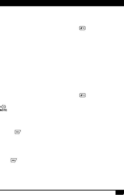
(23) TBST Sel
TBST frequency is used to activate some dormant repeaters, 1000Hz,
1450Hz,1750Hz, 2100Hz a total of 4 options are offered.
Press PTT and PF1 key together to transmit the TBST tone.
(24) VOX
Enable the VOX, you can speak into the microphone to start transmitting
instead of pressing the [PTT] key. A total of 3 levels are provided.
(25) VOX Delay
When the VOX is enabled, set up the VOX delay to help to extend the
transmission time to avoid stopping a transmission too early. 0.5s-3s, a
total of 26 times offered.
(26) Scan Mod
SCM TO: When scanning and stopping for a signal, stays at the channel
5s before resuming the scan.
7. MAIN MENU FUNCTIONS

25 AT-D878UV Digital DMR and Analog UHF/VHF Two Way Radio
SCM CO: When scanning and stopping for signal, stays at the channel
until the signal disappears, and resumes scan 2s later.
SCM SE: When scanning and stopping for a signal, will terminate the scan.
This function is only valid for a VFO scan.
(27) Mic Level
Allows to adjust the Microphone gain, level 1 is the lowest, level and 5 is
highest gain.
(28) DTMF Speed
Offers DTMF encode speed which will help the receiver decode
successfully, 50~500ms are the options.
(29) FM Radio
Turn on or off the FM radio.
(30) FM Radio Moni
Radio Mon On: When FM radio is used, you can still receive or transmit on
the channel.
Radio Mon Off: When FM radio is used, the radio will not permit a
transmission or reception.
(31) Man Down Alarm
When the function is on, the radio will start alarm if the radio is falling to the
ground. Raise the radio to stop the alarm.
When GPS is on and positioning successfully, it will auto send out the GPS
information when the radio starts the alarm.
(32) Start Up Pwd
On: Set up the password for start up. You need to input the password to
power on the radio.
Off: No password is required for the radio power on start up.
The password shall be set up in CPS-Optional Setting-Power on-Power-on
Password Char.
(33-34) AuRepeater A or B (For VFO A or B)
Turn on the Auto Repeater function, the TX frequency in VFO mode will
auto increase or reduce frequency base on the set up offset frequency in
CPS.
Off: Turn off the function.
Positive: TX frequency= RX frequency + Offset frequency.
7. MAIN MENU FUNCTIONS
26
AT-D878UV Digital DMR and Analog UHF/VHF Two Way Radio
Negative: TX frequency= RX frequency - Offset frequency.
(35-44) Key PF1, PF2, PF3, P1, P2
You can program these keys for different functions.(Refer to page 10 & 11)
(45) SMS Format
M-SMS: Allows SMS text communication with Motorola DMR radio.
H-SMS: Allows SMS text communication with Hytera DMR radio.
(46) Time Zone
Set up the time zone of your location.
(47) Date Time
Time Set: Allows to set up the date and time manually. Use the /
key to set the current year. Move to the month by pushing the key. Set
the month, and use the key to move forward each step. Once done,
click the Menu key to save the date and time.
GPS Check: When GPS is positioning successfully, enter this menu, select
GPS check to do the date & time correction automatically.
7.7.2 Chan Set
Channel set menu Route: Main Menu- Settings - Chan Set. The channel
set menu will change accordingly to the channel type. When the channel
type is digital, it will automatical hide the analog menus..
※Chan Set (Digital Channel)
(1) New Chan
Allows creat a new channel and save current set up to the new channel.
a. Select "New Chan", then input new channel number and conrm.
b. Input channel name and conrm.
c. Select a zone and confirm. The new channel will be saved to the
selected zone.
(2) Delete Chan
Allows to delete current channel.
a. Select "Delete Chan",the radio will remind " Delete? "
b. press conrm, the current channel will deleted.
Note: After delete one channel, the radio will move to next channel.
(3) Channel Type
A-Analog : Set up to analog channel
7. MAIN MENU FUNCTIONS

27 AT-D878UV Digital DMR and Analog UHF/VHF Two Way Radio
D- Digital : Set up to digital channel
A+D TX A: Mixed analog, allow receive analog and digital signal, TX is
analog.
D+A TX D: Mixed digital, allow receive analog and digital signal, TX is
digital.
(4) TX Power
Set up the TX power for current channel.
(5) Offset
Press / to adjust offset frequency.
(6) Band Width
Only narrow band 12.5KHz for digital channel.
(7) RX Freq
Input the RX frequency by keypad, click the Menu key to save, press P2
key to return.
(8) TX Freq
Input the TX frequency by keypad, click the Menu key to save, press [P2]
key to return.
(9) Talk Around
When the TX radio and RX radio both are set up with Talk Around on, they
can communicate directly without a repeater. The analog channel will use
the RX frequency as TX/RX frequency, the RX CTCSS/DCS decode as TX
CTCSS/DCS encode.
(10) Name
Allow reset the channel name, this function is only valid in channel mode.
(11) TX Allow
Always: Always allow transmit
Channel Free: Allow transmit when the channel is free
Different CC: Allow transmit when receive matched signal but different color
code.
Same CC: Allow transmit when receive matched signal and same color code.
(12) TX Prohibit
TX ON: Will allow transmit on the current channel.
TX OFF: Will not allow transmit on the current channel.
7. MAIN MENU FUNCTIONS

28
AT-D878UV Digital DMR and Analog UHF/VHF Two Way Radio
(13) Radio ID
In Digital channel, it will show the DMR ID which must be programmed in
the PC software – Digital – DMR ID list- DMR ID. Allows edit and select an
ID for the channel, each channel allows one ID.
In Analog channel, it will show the radio self ID which is programmed in PC
software – Analog –Analog Address Book – Number.
(14) Color Code
The digital channel should have the same color code for communication as
dened by the repeater to be used; which can be programmed in the PC
software or dened in the Menu.
(15) Time Slot
Set up Slot 1 or Slot 2 for the current channel.
(16) Digi Encrypt
With the digital encryption, the communication will be condential. A total
of 32 digital encryptions is offered, and it can be programmed in the PC
software or dened in the Menu.
(17) Encrypt Type
Choose normal encryption or enhanced encryption type.
(18) RX Group List
It will allow edit the RX Group List and assign a new RX Group List to the
channel.
Select Cur List: Select the current RX Group List.
Add Group: Add a TG to the current RX Group List.
Remove Group: Remove a TG from the current RX Group List.
(19) Work Alone
In the PC software – Public – Alarm settings – Work Alone, you have to set
up the response time, warn time and response method initially.
Turn on the work alone function for the current channel. When the radios
predetermined time has been reached for the alone working time, the radio
will beep a sound and show “Work Alone Predict”. The user has to conrm
by pushing the programmed work alone key to confirm continuing work
alone, otherwise, the radio will start its alarm and send the alarm on the
channel when reaching its preset response time.
7. MAIN MENU FUNCTIONS

29 AT-D878UV Digital DMR and Analog UHF/VHF Two Way Radio
(20) CH Ranging
In standby, if the call contact type for a channel is "Private call", The radio
will automatically start ranging function when turned to this channel. The
other radio's location will be showed on screen at intervals.
(21) APRS Receive
Turn APRS Receive, if both radio GPS is positioned, the radio will display
the other radio's distance and position when radio is receiving.
(22) DMR Mode
Simplex: Enable to communicate by repeater frequencies directly with
another radio with opposite TX/RX frequncies.
Repeater: Enable talk with other radio by repeat frequency throught
repeaters.
Double Slot: When TX/RX frequency is same, turn on this function to
communicate by the slot set in simplex mode.
Note: If DMR mode not choosed Doulbe Slot, the radio will work on Slot in
repeat mode. if choose Double Slot, it is necessary to Double choose a slot
by time slot setting.
(23) Slot Suit
Turn on Slot suit, the radio will receive calling from both slot, and will be
able to call back in corresponding slot.
※Chan Set (Avaiable in Analog Channel only)
When the channel type is analog, it will automatically hide the digital menu,
The below listed menus are for analog channel only, unlisted menus are
are the same as the digital channel, please refer to Chan Set (Digital
Channel).
(4) TCDT
Set up the CTCSS/DCS code for the TX.
(5) RCDT
Set up the CTCSS/DCS code for the RX.
(6) RTCDT
Set up the CTCSS/DCS code for both TX and RX
CTCSS code: 62.5Hz~254.1Hz, a total of 51 groups
DCS code: 000N~7771, a total of 1024 groups.
(7) Optional Signal
7. MAIN MENU FUNCTIONS

30
AT-D878UV Digital DMR and Analog UHF/VHF Two Way Radio
Allows the setup of DTMF/5TONE/2TONE encode and decode for the
Analog channels.
(10) Squelch mode
When the analog channel is set up for both CTCSS/DCS decoding and
optional signaling, you can set up the RX condition in this menu.
SQ: You can hear the call once the channel receive matched carrier.
CDT: You can hear the call when receive matched CTCSS/DCS signal.
TONE: You can hear the call when receives a matched signaling.
C&T: You can hear the call when receives a matched CTCSS/DCS and
matched signaling.
C|T: You can hear the call when receives a matched CTCSS/DCS or.
(11) Band Width
Choose wide band or narrow band for the analog channel.
(12) Reverse
When this function is enabled, the RX frequency, TX frequency and
CTCSS/DCS encode/decode will be reversed.
(17) Busy Lock
Always: Always allows transmissions
RL: Will not allow transmit when receiving matched carrier but unmatched
CTCSS/DCS.
BU: Will not allow transmit when receiving matched carrier.
(19) OWN ID
When the analog channel set up with optional signal, you can check the
radio ID number in this menu. The ID number should be set up in PC
software – Analog – Analog Address Book.
(20) DTMF Enc
Set a DTMF ID as the default call ID for the current channel.
Press the PTT key to transmit the selected DTMF ID.
Edit the DTMF ID in Menu or with the PC programing software.
(21-22) 2Tone Enc
Set a 2Tone as the default call ID for the current channel.
Press the PTT key to transmit the selected 2Tone.
Edit the 2Tone in the PC programing software before it can be selected.
7. MAIN MENU FUNCTIONS

31 AT-D878UV Digital DMR and Analog UHF/VHF Two Way Radio
(23-24) 5Tone Enc
Set a 5Tone as the default call ID for the current channel.
Press the [PTT] key to transmit the selected 5Tone.
Edit the 5Tone in the PC programing software before it can be selected.
7.7.3 Device Info
Show the Radio ID, Radio name, serial number, model name, frequency
range, rmware version, radio data version, latest program date, picture
version, language version etc.
9. MAIN MENU
7.8.1 Turn On/ Off the Recording
7.8 Record
7.8.2 Play the Record
a. Press (Menu) enter main Menu, press / key to Record.
b. Select Talk Record, then
•Select Record Switch, select on or off to turn on or off the recording.
a. Press (Menu) to enter main Menu, press / key to Record.
b. Select Record List to enter Record list, select a Record list to enter the
Record le.
c. Select a Record to see the Detailed Information.
d. Press Select to choose the record option.
1) Record Play, it will play one record at a time, you can press / key to
switch the recording without return to previous menu.
2) Loop Playback, it will play all records in circle.
The voice record is designed for security use purpose. Each call will
be saved as a separated recording ile with DMR ID and time details.
The standard voice 10hours record allows in DMR mode only. The
optional 500 hours voice record allow in both DMR or analog mode.
7.8.3 Send the Record
a. Press (Menu) to enter main Menu, press / key to Record.
b. Select Record List to enter Record list, select a Record list to enter the
Record le.
7. MAIN MENU FUNCTIONS
32
AT-D878UV Digital DMR and Analog UHF/VHF Two Way Radio
»The Recording function is only valid in digital channel.
7.8.4 Recording Manually
In the PC software, Public – Optional Setting – Key function, program a key
as Record.
a. Press the programmed Record key, and the radio will start the recording,
and speak into the microphone.
b. Select Record Play, and the radio will play the record.
c. Select Record Send, and the radio will display Contact list or Manual
Dial.
d. Select Contact list to choose a contact, and press select to send the
Record.
e. Select Manual Dial, input the DMR ID, press key to switch group ID
or private ID, press select to send the Record.
c. Select a Record to see the detail information.
d. Select Record Send, and it will display the Contact list or Manual Dial.
e. Select Contact list to choose a contact, press select to send the Record.
f. Select Manual Dial, input the DMR ID, press key to switch group ID
or private ID, press select to send the Record.
7.9.1 Turn on GPS
7.9 GPS Positioning Function(optional with installed GPS)
7.9.2 GPS Info
a. Press (Menu) to enter the main Menu.
b. Select "GPS".
c. Select "GPS On".
Method 1: Check GPS info from Menu
Press (Menu) key to enter Main Menu, select "GPS", then select "GPS
Info".
Method 2: Check GPS info from programmed key
In the PC software, Public – Optional Setting – Key function, program a key
as "GPS Info", then press the programmed key to check the GPS info.
7. MAIN MENU FUNCTIONS
33 AT-D878UV Digital DMR and Analog UHF/VHF Two Way Radio
7.9.3 Send GPS Information
a. When the GPS is positioning successfully, the GPS icon shows a red
color. Follow the above step to check the GPS info, press edit key to
Text edit.
b. Press Conrm, and it will display Send or Save. If you select Save, the
GPS info will be saved as a draft message.
c. Choose Send and it will display Contact list or Manual Dial.
d. Select Contact list to choose a contact, press select to send the GPS
info. or
e. Select Manual Dial, input the DMR ID, press key to switch group ID
or private ID, press to send the GPS info.
»If the GPS is not positioning, it will display “No Fixed Position”,
and the GPS icon shows a grey color. Move the radio to an open
window or outdoors, and it will take a few minutes to connect to
the GPS Satellites.
7.10 APRS Location Reporting(Supported by GPS)
(1) Upload Type
None: No APRS.
Sel A Aprs: Select analog APRS.
Sel D Aprs: Select DMR APRS.
(2) Ana APRS
PTT Upload: Set the PTT transmit method.
● Off: Not transmit APRS.
● Tx Start: Transmit analog APRS when press the PTT.
● TX End: Transmit analog APRS when release the PTT.
Upload Power: Set the transmit power.
Upload frequency: Set the transmit frequency.
Upload text: Set the text to be shown on aprs.
(3) Digi APRS
PTT Upload: Set the PTT transmit method.
● Off: Not transmit APRS.
● On: Transmit DMR APRS when release the PTT.
7. MAIN MENU FUNCTIONS

34
AT-D878UV Digital DMR and Analog UHF/VHF Two Way Radio
(4) Digi APRS Info
The received APRS information will be saved in radio for look back use.
Click on "Digi APRS Info" will show the received APRS information.
Click on "Delete All" will clear the information.
(5) Intervals Set
This function allows you to set the analog APRS or DMR APRS auto
transmit at xed times.
(6) Upload Beacon
GPS Beacon: The APRS will transmit the GPS data, only if the GPS is set
to on rst, then GPS must also successfully lock on the satellites.
Fixed Beacon: The APRS will transmit the xed beacon data. Someone
can transmit the xed beacon without setting the GPS on. The xed beacon
location information should be set in CPS rstly.
Note: More setup are available by PC software only. CPS-Tools-Options-
APRS, you have to check on the APRS box rst to get APRS menu add to
the left Digital menu.
(APRS is a registered trademark of Bob Bruinga, WB4APR)
7.11 Digital Monitor
a. Press (Menu) key to enter main menu, press / key to
choose Digi Moni function.
b. Press Select to enter Digi Moni menu, press / key to choose a
sub menu.
1) DigiMoni Switch
off: Turn off Digital Monitor
Single Slot: Monitor the current TS
Double Slot: Monitor TS1 and TS2
2) DigiMoni Cc
Any Cc: Monitor any color code
Same Cc: Monitor the same color code
Report Channel: Allow user to select a channel to transmit the DMR
APRS, please set the 8 report channels in CPS-APRS-Digi page rst.
Upload Slot: Allow user to select a slot to transmit the DMR APRS.
● Channel Slot: It uses the slot of current channel
● Slot 1: Use slot 1
● Slot 2: Use slot 2
7. MAIN MENU FUNCTIONS
35 AT-D878UV Digital DMR and Analog UHF/VHF Two Way Radio
7.11.1 Response and Save a call in Digital Monitor Mode
During Digital Monitor, when receive a call with unmatched ID, press
key, the screen will display "Monitor Response Setup Successfully", press
[PTT] key will reponse to the call.
Press key, the radio will remind you choose a Zone, press /
key to choose a Zone, press select key to save the new channel to the
Zone.
3) DigiMoni Id
Any Id: Monitor any TG
Same Id: Monitor the same TG
4) Slot Hold
Off: Turn off the slot hold
On: Turn on the slot hold
Recommend to turn on slot hold when monitor double slot TS1 and TS2, when
the signal is disappear in one slot, instead of switching to the other slot at once,
the radio will hold on some seconds and wait for the audio drop.
c. Press Select to enter the sub menu and set up.
7. MAIN MENU FUNCTIONS
7.12 Bluetooth function (Optional with installed Bluetooth)
1) BHT Switch
It will allow select “Bluetooth ON” or “Bluetooth OFF”, select “Bluetooth ON” to
turn on the bluetooth function.
2) BHT Match
It will allow select “Enter Match” or “Exit Match”, select “Enter Match” to start the
bluetooth pairing.
3) Device Name
It will show the bluetooth information and version.
4) MIC while BHT
When bluetooth function is on, the radio microphone is default off. This function
will allow you turn on the radio microphone.
5) Speaker while BHT
When bluetooth function is on, the radio speaker is default off. This function will
allow you turn on the radio speaker.
6) BHT MIC Gain
This function will allow you select different MIC gain level for bluetooth headset.
7) BHT SPK Gain
This function will allow you select different speaker gain level for bluetooth
headset.

36
AT-D878UV Digital DMR and Analog UHF/VHF Two Way Radio
a. Power off the radio rstly.
b. Then power it on while holding the [PTT] and the [PF1] button below the
PTT at the same time.
c. The radio will start up with a note on the display – “Are you sure you
want to initialize radio?”
Press Exit to exit the reset and power on the radio.
Press Conrm to proceed the reset, it will come with a screen display
note – Initialize Radio.
d. After a re-start the radio will display the setting of time zone and the
date and the time. Use the up-down key to set the current year. Move to
the month by pushing the P1 key. Set the month, and use the P1 key to
move forward each step. Once done, click the Conrm key to save the
date and time.
Please remember set up the time zone to avoid the date/time error.
Make sure the codeplug is saved to PC before your do the update and
reset.
8. RESET

37 AT-D878UV Digital DMR and Analog UHF/VHF Two Way Radio
Problems Solutions
The radio cannot be switched
on or no display after being
switched on.
A. Battery pack may not be installed
properly. Remove the battery pack
and install it again.
B. Battery power may be insufcient.
Recharge or replace the battery
pack.
The battery doesn't last very
long after charging.
The battery is defective; please replace it
with a new battery pack.
Cannot talk to or hear other
members in your group.
Other voices from
non-group members are heard
on the channel.
Analog: Change the CTCSS/DCS
Tone, and make sure to change the tone
on all radios in your group.
1. Make sure the frequency and
CTCSS are the same as other
members.
2. Make sure you are within range,
and not too far away from your
member.
3. Make sure you are set in correct
digital mode, and frequency.
4. In digital mode, make sure set
correct code and encrypt group is
used in current channel.
5. n digital mode, make sure set
correct receiving contacts and
receiving group is used.
9. TROUBLE SHOOTING GUIDE

38
AT-D878UV Digital DMR and Analog UHF/VHF Two Way Radio
10. PROGRAMMING GUIDE
Multiple Radio ID’s
Amateur DMR-MARC
Anytone AT-D878UV radios ship from the manufacturer “Keypad” locked
per FCC rules.
You can press the (Menu) key and the (star) key to unlock the
keypad for the rst time of use. You will need the programming cable to
connect your radio to your computer for programming.
The programming software and codeplug programming guide are available
for download from Anytone website:
http://www.anytone.net/about/about8.html
When programming this radio for the first time, it is recommended you
first READ the radio with the software and then save this file for future
reference as it contains the default programming and settings. In addition,
after you READ this radio with software, rst make your programming and
frequency changes, then send this edited le back to your radio.
The AT-D878UV radio will allow multiple DMR Radio ID numbers to be
used with the radio. This feature will allow one radio to be used for example
as a Commercial Radio with its own DMR ID, and at the same time also be
used as an Amateur radio with another DMR ID.
In PC software, Digital/ Radio ID List, you can enter your Department Unit
Number or Amateur Radio callsign.
For the best Amateur DMR experience obtain a subscriber ID from one of
many available Amateur Radio sources. A U.S. Amateur can obtain a DMR
ID From:
https://www.radioid.net/cgi-bin/trbo-database/register.cgi
For DMR repeaters in your area please see: www.repeaterbook.com
World DMR repeater network map:
https://www.repeaterbook.com/index.php/repeater-database
World DMR repeater network with veried Talkgroups by activity:
https://brandmeister.network/?page=lh

39 AT-D878UV Digital DMR and Analog UHF/VHF Two Way Radio
The AT-D878UV DMR radios contain a separate database memory for
importing and displaying Amateur DMR individual IDs, call sign and user
name in comma-delimited format (.csv)
Please reference in the programming guide for import and export database
operations detailed.
User List Contact Database: https://ham-digital.org/status/
Worldwide Amateur Contact Database
10. PROGRAMMING GUIDE

40
AT-D878UV Digital DMR and Analog UHF/VHF Two Way Radio
The Anytone website provides additional information about obtaining
service or support for the Anytone line of two-way radios and accessories.
Visit: www.anytone.net
Warning Notes
Every effort has been made to ensure that the information in this document
is complete, accurate, and up to-date. Anytone Radio assumes no
responsibility for the results of errors beyond its control. The manufacturer
of this equipment also cannot guarantee that changes in the equipment
made by non-authorized users will not affect the information in it.
FCC Licensing Information
This Anytone radio operates on Commercial / Land Mobile frequencies
which require a license from the Federal Communications Commission
(FCC) for business, personal, education and recreational use. To obtain
forms, call the FCC forms hotline at: 1-800-418-3676 or go to http://www.
fcc.gov
For questions concerning commercial licensing, contact the FCC at
1-888-CALL-FCC (1-888-225-5322).
11. ON-LINE SERVICE AND SUPPORT

41 AT-D878UV Digital DMR and Analog UHF/VHF Two Way Radio
The Anytone AT-D878UV DMR handheld transceiver has been carefully
designed to provide you with years of safe, reliable operation. As with
all electrical equipment, however, there are a few basic precautions you
should take to avoid hurting yourself or damaging the radio:
• Read the instructions in this handbook carefully. Be sure to save it for
future reference.
• Read and follow all warning and instruction labels on the radio and
owner’s manual.
• Do not carry the transceiver by the antenna. This may damage the
antenna or antenna terminal. Grasp the handheld by its base (not the
antenna) when you need to place or remove it.
• Do not keep the radio with the antenna very close to, or touching exposed
parts of the body, while transmitting. Anytone radios will perform best, if
you speak 2-4 inches away from the microphone and the radio is vertical.
• Be sure the “PTT” key is not pressed when you do not need to transmit.
• Do not operate the radio near unshielded electrical blasting caps or in an
explosive atmosphere.
• Do not transmit without the antenna fitted on the radio. Though it is
provided with a protection, it may damage the TX output nal stage.
• Respect the environment conditions. The radio is designed to be used in
heavy environments, however avoid exposing it to extremely hot or cold
temperature (out of the range between –20°C to +55°C). Do not expose
the transceiver to excessive vibrations as well as dusty or rainy locations.
• Never try to disassemble or service the radio by yourself (aside from the
routine maintenance described in this handbook). It may cause damage
to the radio transceiver and void your warranty requiring extensive repair
work. Always contact your local dealer for assistance.
• Use only authorized accessories. Using non Anytone radio brand
accessories may seriously damage your handheld transceiver and void
your warranty.
• Do not spill liquid of any kind into your radio. If the transceiver gets wet,
immediately dry it by a soft and clean cloth.
• Switch the radio off before you clean it. Follow the directions described in
the paragraph “Care and maintenance”.
SAFETY

42
AT-D878UV Digital DMR and Analog UHF/VHF Two Way Radio
• Handle the battery properly. Never place the LI-ion battery in your pocket
or purse with loose coins. This could result in short circuiting the battery.
• Be certain that your power source matches the rating listed for the
supplied battery charger (AC adapter). If you are not sure, check with your
authorized Anytone dealer.
• Avoid damaging the power cable of the battery charger. Do not step on
or place anything on it as this could result in a damaged charger power
cord. This product complies with the requirements of the Council Directives
89/336/EEC and 73/23/EEC on the approximation of the laws of the
member states relating to electromagnetic compatibility and low voltage.
Your wireless hand-held portable transceiver contains a low power
transmitter. When the Push-to-Talk (PTT) button is pressed it sends out
radio frequency (RF) signals. The device is authorized to operate at a duty
factor not to exceed 50% TX and 50% RX.
In August 1996, the Federal Communications Commission (FCC) adopted
RF exposure guidelines with safety levels for hand-held wireless devices.
To maintain compliance with the FCC’s RF exposure guidelines, this
transmitter and its antenna must maintain a separation distance of least 2
inches from your face. Speak in a normal voice, with the antenna pointed
up and away from the face at the required separation distance. The belt
clip is for storage purposes only.
AVOID TRANSMITING ON HIGH POWER WHILE RADIO IS ATTACHED
TO YOUR BELT. To transmit, hold the device away from your body and
ensure the antenna is at least 2 inches from your body when transmitting.
WARNING
SAFETY
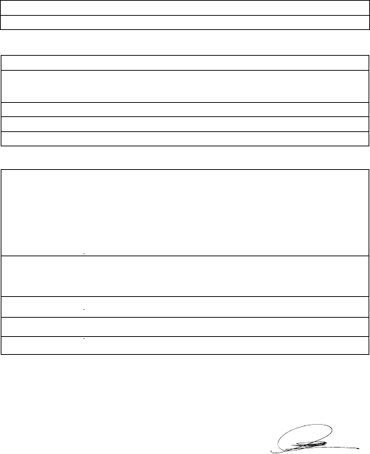
EU DECLARATION OF CONFORMITY
In accordance with EU Directives and Regulations, the undersigned
hereby declare that the following equipment is in conformity with the
essential requirements of the RE Directive 2014/53/EU.
The notified body Bay Area Compliance Labs Corp.(BACL) (EU
Identification Number: 1313) performed a conformity assessment
according to Annex III, Module B. Signed on behalf of Qixiang Electron
Science & Technology Co., Ltd.
1. INFORMATION ON THE EQUIPMENT
Product: Digital DMR and Analog UHF/VHF Two Way Radio
Model Name: AT-D878UV
2. INFORMATION ON THE MANUFACTURER
Manufacturer: Qixiang Electron Science & Technology Co., Ltd.
Address:Qixiang Building,Tangxi Industrial Zone,Luojiang
District,Quanzhou,Fujian, China
Name: Ken XU (General Manager)
Tel: +86 595 22656926
Mail: ken6833@qxdz.cn
3. INFOMRATION ON THE STANDARDS
RF
EMC EN 301 489-1/-5/-15/-17/-19
EN 550 32, EN 550 35
EN 610 00-3-2, EN 610 00-3-3
EN 300 086
EN 300 219
EN 300 113
EN 301 783
EN 303 413
EN 303 345
EN 300 328
LVD/Safety
MPE
EN 609 50-1
EN 624 79, EN 506 63
SAR EN 505 66
Date: 2018-Sep-19
Signature:
44
AT-D878UV Digital DMR and Analog UHF/VHF Two Way Radio
EU DECLARATION OF CONFORMITY
In accordance with EU Directives and Regulations, the undersigned
hereby declare that the following equipment is in conformity with the
essential requirements of the RE Directive 2014/53/EU.
The notified body Bay Area Compliance Labs Corp.(BACL) (EU
Identification Number: 1313) performed a conformity assessment
according to Annex III, Module B. Signed on behalf of Qixiang Electron
Science & Technology Co., Ltd.
1. INFORMATION ON THE EQUIPMENT
Product: Digital DMR and Analog UHF/VHF Two Way Radio
Model Name: AT
-
D878UV
2. INFORMATION ON THE MANUFACTURER
Manufacturer:
Qixiang Electron Science & Technology Co., Ltd.
Address:
Qixiang Building,Tangxi Industrial Zone,Luojiang
District,Quanzhou,Fujian, China
Name:
Ken XU (General Manager)
Tel:
+86 595 22656926
Mail:
ken6833@qxdz.cn
3. INFOMRATION ON THE STANDARDS
RF
EMC EN 301 489-1/-5/-15/-17/-19
EN 550 32, EN 550 35
EN 610 00-3-2, EN 610 00-3-3
EN 300 086
EN 300 219
EN 300 113
EN 301 783
EN 303 413
EN 303 345
EN 300 328
LVD/Safety
MPE
EN 609 50-1
EN 624 79, EN 506 63
SAR EN 505 66
Date: 2018-Sep-19
Signature:
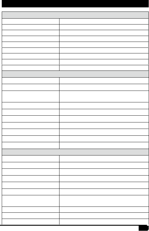
12. TECHNICAL SPECIFICATIONS
General
Frequency Range 136-174MHz (V) , 400-480MHz (U)
Channel Capacity 4000 channels
Channel Spacing 12.5KHz (Narrow Band)
Phase-locked Step 5KHz, 6.25KHz
Operating Voltage 7.4V DC ±20%
Frequency Stability ±2.5ppm
Operating Temperature -10℃~ +40℃
Size 129×61×39mm (with battery pack)
Weight 282g (with battery pack, antenna)
Receiving Part
Narrow band
Sensitivity(12dB SINAD) ≤0.35μV
Digital Sensitivity 0.3uV/-117.4dBm (BER 5%)
0.7uV/-110dBm (BER 1%)
Adjacent Channel Selectivity ≥60dB
Spurious Emission ≤-57dB
Spurious Rejection ≥70dB
Blocking 84db
Hum & Noise ≥40dB
Audio Distortion ≤5%
Audio Power Output 1000mW/16Ω
Transmitting Part
Narrow band
Power Output VHF: 7/5/2.5/1W, UHF: 6/5/2.5/1W
Modulation ±2.5KHz@12.5KHz
Adjacent Channel Power ≥60dB
Hum & Noise ≥36dB
Spurious Emission ≤-36dBm
4FSK Digital Modulation 12.5KHz(data)7K60FXD
12.5KHz(data+voice)7K60FXE
Audio Distortion ≤5%
Error rate ≤3%
FM Modulation 12.5KHz 11K0F3E
European Users should note that operation of this unit in Transmit mode
requires the operator to have a valid Amateur Radio Licence from their
respective Countries Amateur Radio Licencing Authority for the Frequencies
and Transmitter Power levels that this Radio transmits on. Failure to comply
may be unlawful and liable for prosecution. At this subject, refer to the “EU”
specication guide 2014/53/EU.
Products with the symbol (crossed-out wheeled bin) cannot be
disposed as household waste. Electronic and Electric Equipment
should be recycled at a facility capable of handling these items and
their waste by products.
In EU countries, please contact your local equipment supplier
representative or service center for information about the waste
collection system in your country.
This transceiver works on frequencies which are
not generally permitted. As for the actual usage,
the user has to possess an amateur radio licence.
Usage is allowed only in the frequency bands
which are allocated for amateur radios.
Disposal of your Electronic and Electric Equipment
List of national codes
AT BE BG CY CZ DE
DK ES EE FI FR GB
GR HR HU IE IT LT
LU LV MT NL PL PT
RO SK SI SE CH IS
LI NO ----
Attention in case of use

SAFETY TRAINING INFORMATION
our Qixiang Electron Science& Technology Co., Ltd radio generators RF electromagnetic
during transmit mode.This radio is designed for and classified as"Occupational Use Only",
meaning it must be used only during the course of employment by individuals aware of the
hazards,and the ways To Minimize Such hazards. This radio is NOT intended for use by the"General Population"
in an uncontrolled environment. This radio has been tested and complies with the FCC RF exposure limits for
"Occupational Use Only".Inaddition, our Qixiang Electron Science& Technology Co., Ltd radio complies with the
following Standards and Guidelines with regard to RF energy and electromagnetic energy levels and evaluation
of such levels for exposure to humans:
--IEEE Std. 1528:2013 and KDB447498, Evaluating Compliance with FCC Guidelines for Human
Exposure to Radio Frequency Electromagnetic Fields.
--American National Standards Institute (C95.1-1992), IEEE Standard for Safety Levels with Respect to
Human Exposure to Radio Frequency Electromagnetic Fields, 3 kHz to 300 GHz.
--American National Standards Institute (C95.3-1992), IEEE Recommended Practice for the Measurement
of Potentially Hazardous Electromagnetic Fields- RF and Microwave.
The information listed above provides the user with the information needed to make him or
her aware of RF exposure, and what to do to asÿsure that this radio operates with the FCC RF
exposure limits of this radio.
Electromagnetic Interference/Compatibility
During transmissions, Qixiang Electron Science& Technology Co., Ltd radio generates RF energy that can
possibly cause interference with other devices or systems. To avoid such interference, turn off the radio in
areas where signs are posted to do so. DO NOT operate the transmitter in areas that are sensitive to
electromagnetic radiation such as hospitals, aircraft, and blasting sites.
Occupational/Controlled Use
The radio transmitter is used in situations in which persons are exposed as consequence of their employment
provided those persons are fully aware of the potential for exposure and can exercise control over their exposure.
Attention:
This radio complieswith IEEE and ICNIRP exposure limits for occupational/controlled RF exposure
emvironment at operating duty factors of up to 50% and is authorized by the FCC for occupational use only. An
appropriate warning lable is affixed to all units. In order to comply with RF exposure requirements, a minimum
distance of 2.5cm must be maintained when held-to-face, and body-worn operations are restricted to the approved
original acessories (belt clip)
This product is compliance to FCC RF Exposure requirements and refers to FCC website
https://apps.fcc.gov/oetcf/eas/reports/GenericSearch.cfm search for FCC ID:T4KD878UV to gain further
information include SAR Values.
FCC NOTICES
a minimum distance of 0cm,Don't use this device when antenna shows obvious
danages.

EQUIPMENT NOTICES
Changes or modifications not expressly approved by the party responsible for compliance
could void the user’s authority to operate the equipment.
This equipment has been tested and found to comply with the limits for a Class B digital
device, pursuant to Part 15 of the FCC Rules. These limits are designed to provide
reasonable protection against harmful interference in a residential installation. This
equipment generates, uses and can radiate radio frequency energy and, if not installed and
used in accordance with the instructions, may cause harmful interference to radio
communications. However, there is no guarantee that interference will not occur in a
particular installation.
If this equipment does cause harmful interference to radio or television reception, which can
be determined by turning the equipment off and on, the user is encouraged to try to correct
the interference by one or more of the following measures:
-- Reorient or relocate the receiving antenna.
-- Increase the separation between the equipment and receiver.
-- Connect the Equipment into an outlet on a circuit different from that to which the receiver
is connected.
-- Consult the dealer or an experienced radio/TV technician for help.
This device complies with part 15 of the FCC rules. Operation is subject to the following two
conditions:
(1) This device may not cause harmful interference, and
(2) This device must accept any interference received, including interference that may cause
undesired operations.