Qixiang Electron Science and Technology QZQX3318 Two Way Radio User Manual
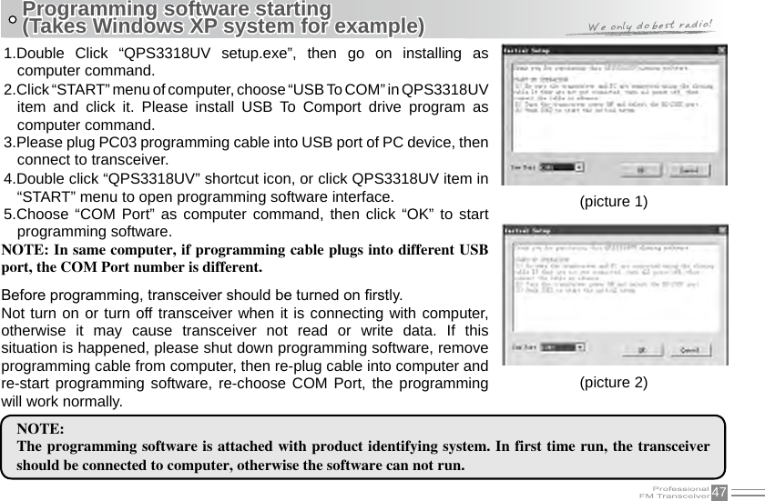
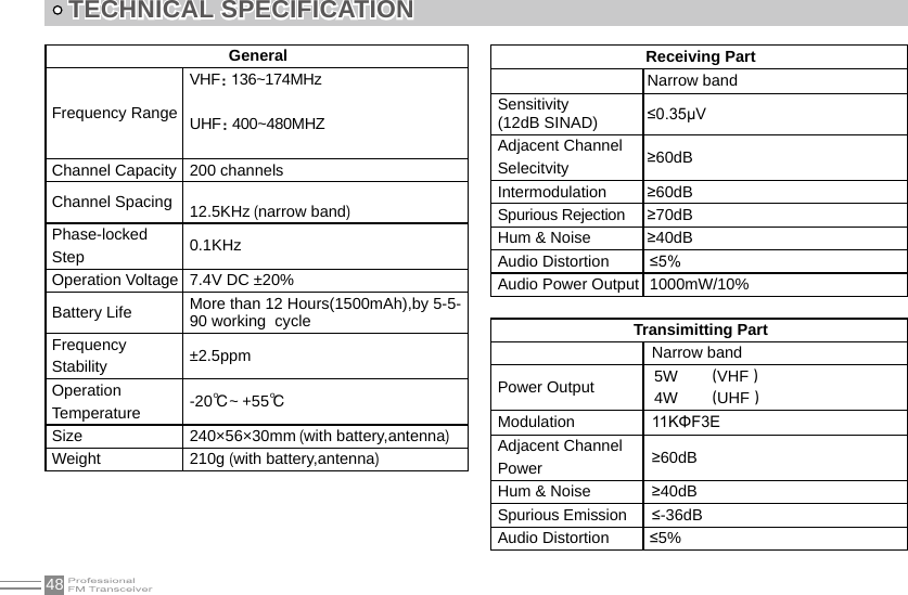
Qixiang Electron Science& Technology Co., Ltd Two Way Radio
UserManual.wiki
>
Qixiang Electron Science and Technology
>
QZQX3318 User Manual
user manual
Navigation menu
Upload a User Manual
Namespaces
Wiki Guide
HTML
PDF
Info
Views
User Manual
Discussion / Help
Navigation

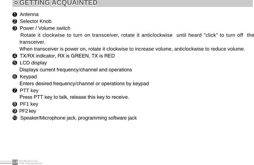
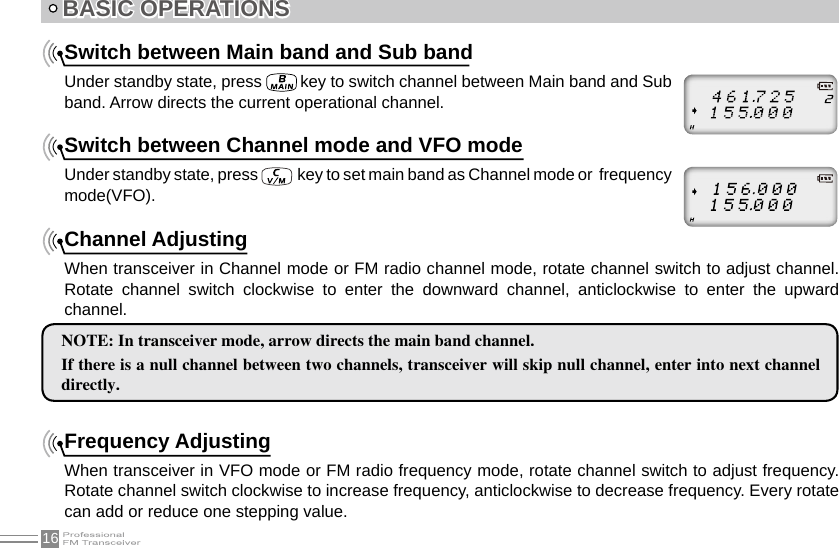
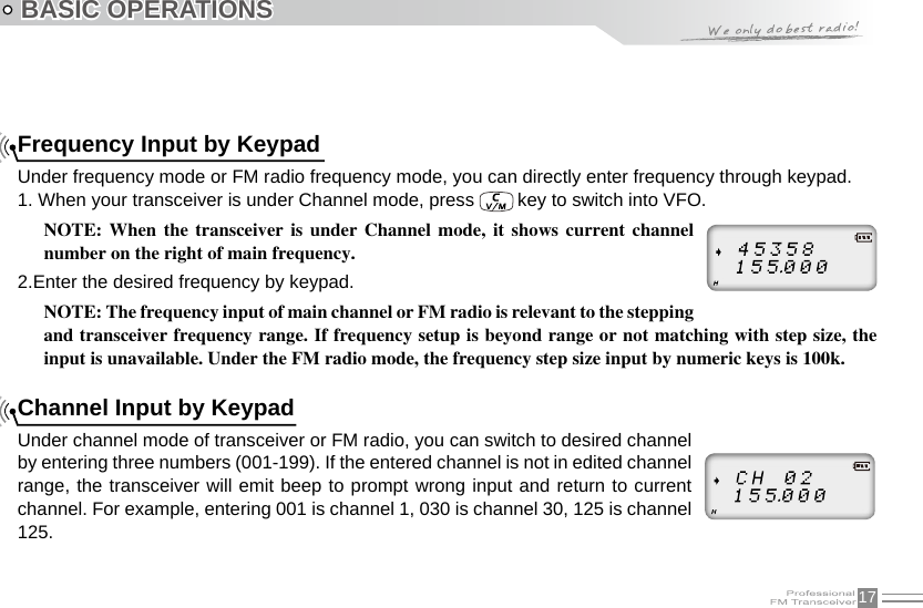
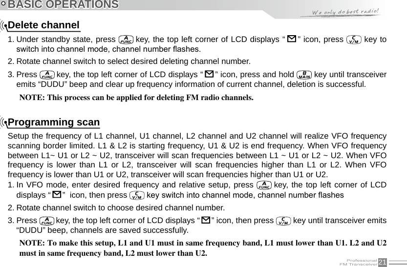
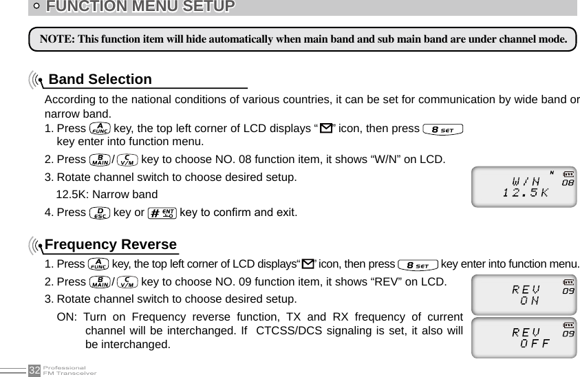
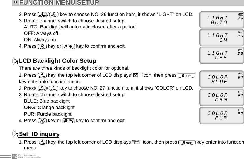
![IITABLE OF CONTENTSSwitch between Main band and Sub band ...............................................................................................................................16Switch between Channel mode and VFO mode ....................................................................................................................16Channel Adjusting ................................................................................................................................................................................. 16Frequency Adjusting .............................................................................................................................................................................16Frequency Input by Keypad .............................................................................................................................................................17Channel Input by Keypad .................................................................................................................................................................. 17FM Channel Searching .......................................................................................................................................................................18Squelch Off Momentary / Squelch Off .........................................................................................................................................18Receiving ...................................................................................................................................................................................................18Transmitting ..............................................................................................................................................................................................19Emergency Alarm ..................................................................................................................................................................................19Side Key [PF1] function instruction ...............................................................................................................................................19Side key [PF2] function instruction................................................................................................................................................20Edit channel ..............................................................................................................................................................................................20Delete channel ........................................................................................................................................................................................21Programming scan ................................................................................................................................................................................21SHORTCUT OPERATIONS ..............................................................................................................................................................22Turn On/ Off FM Radio........................................................................................................................................................................ 22Add/Cancel Optional signal decode function ...........................................................................................................................22CTCSS/DCS Scan ................................................................................................................................................................................23Offset Frequency Direction Setup ................................................................................................................................................. 23Frequency/Channel Scan .................................................................................................................................................................. 24Channel Scan Skip ...............................................................................................................................................................................24Frequency Reverse ..............................................................................................................................................................................25TX Power selection ...............................................................................................................................................................................25](https://usermanual.wiki/Qixiang-Electron-Science-and-Technology/QZQX3318/User-Guide-2261952-Page-6.png)
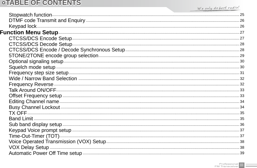
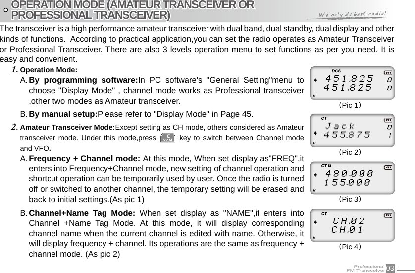
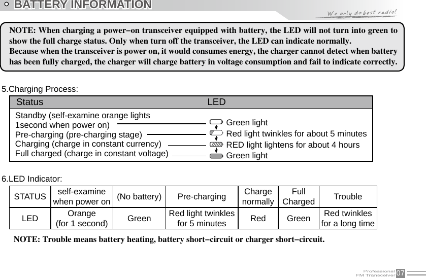
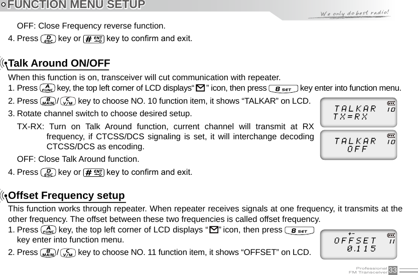
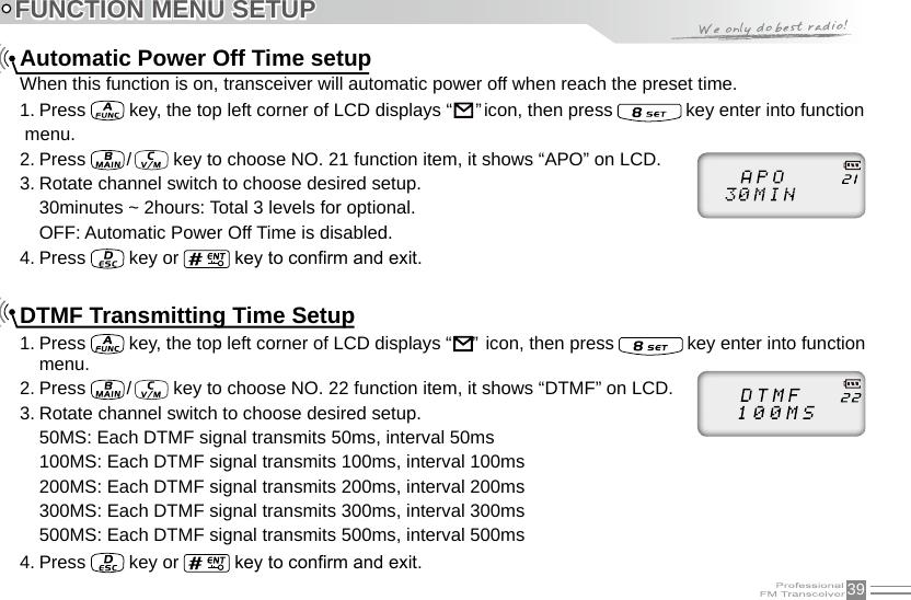
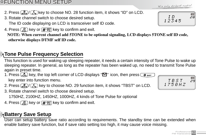
![15 Turn the Radio On & OFFNOTE:Press the side key programmed as Squelch Off Momentary to monitor the background noise. Turn [POWER]/ [VOLUME] to control the volume.The volume you need can be adjusted more correctly when communicating with the other party.BASIC OPERATIONSUnder power-off state, please turn [POWER]/ [VOLUME] clockwise to turn on the transceiver.Under power-on state, please turn [POWER]/ [VOLUME] anticlockwise to turn off the transceiver.Under power-on state, turn [POWER] / [VOLUME] to adjust volume. Clockwise-up, anticlockwise -down.When adjusting the volume, user can press the key programmed as Squelch Off to monitor current volume rstly.Adjusting Volume](https://usermanual.wiki/Qixiang-Electron-Science-and-Technology/QZQX3318/User-Guide-2261952-Page-23.png)
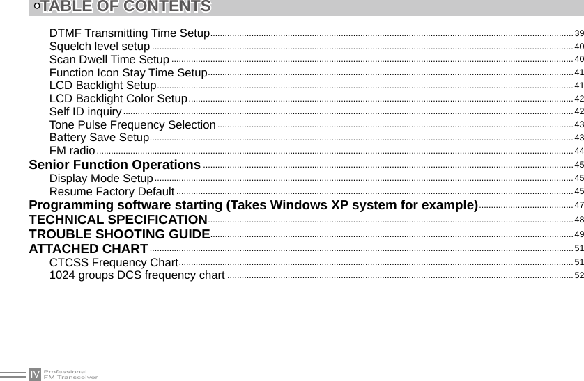
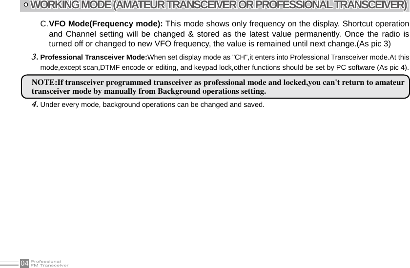
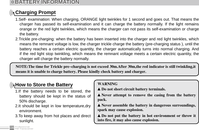
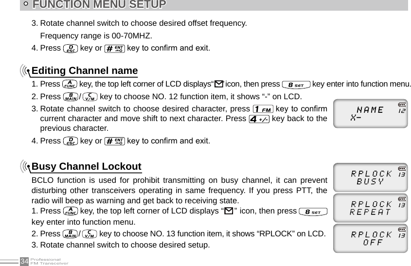
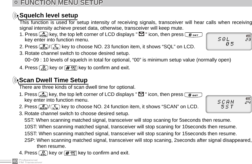
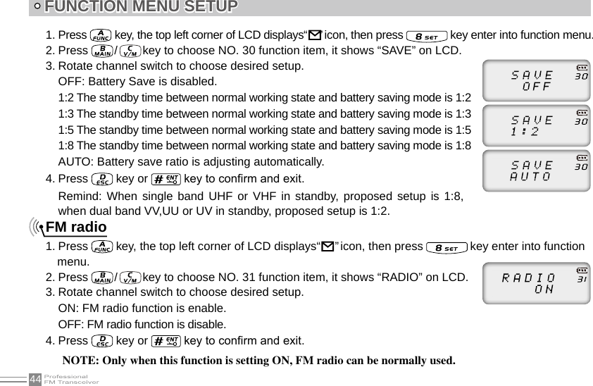
![18 BASIC OPERATIONSFM Channel SearchingWhen transceiver in FM radio mode, press key, LCD displays FUNC icon, then press to start FM searching. When one station is sought, LCD displays current station frequency, you can listen to current station. Squelch Off Momentary / Squelch OffSide key [PF2] can be setup for Squelch off Momentary or Squelch off function by programming software.1.Squelch off: Press [PF2] key, squelch circuit is not mute, back-ground noise can be heard. Press [PF2] key again, squelch circuit is mute.2.Squelch off Momentary: Press and hold [PF2] key, squelch circuit is not mute, back-ground noise can be heard. Release [PF2] key, squelch circuit is mute.NOTE: The above functions are only available after [PF2] key setup in programming software.ReceivingWhen your transceiver is called by other party, the green LED light will be on and the arrow icon will ash, you can hear the calling.NOTE: You may not receive the calling when your transceiver is set at high squelch level. If current channel is programmed with decode signal, only the same signaling call can be heard .](https://usermanual.wiki/Qixiang-Electron-Science-and-Technology/QZQX3318/User-Guide-2261952-Page-26.png)
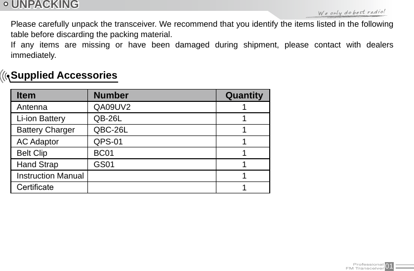
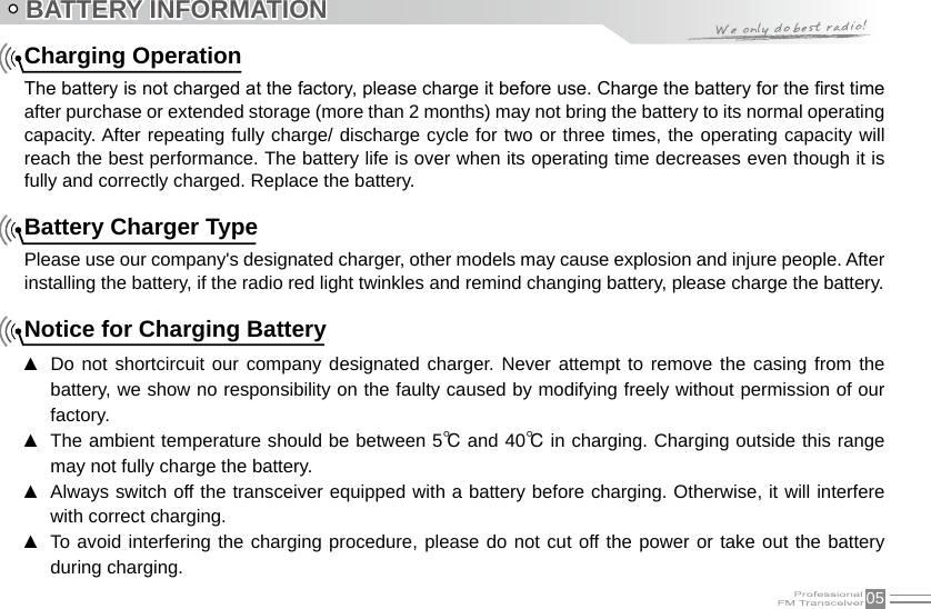
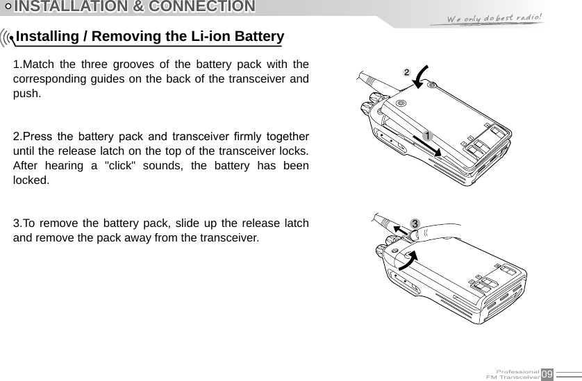
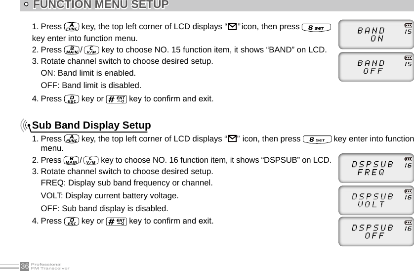
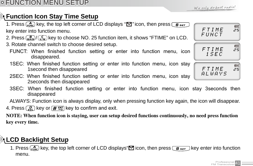
![19BASIC OPERATIONSTransmittingAccording to [PF2] key setup in programming software, hold [PF2] key to monitor the channel to ensure it is not busy, press PTT key and talk to speaker.Please keep the distance between mouse and speaker to be 2.5-5CM, speak in normal tone to get the best acoustic delity.NOTE: When press and hold PTT key, transceiver is transmitting if the red LED light is on, release PTT key to receive calls. Emergency AlarmUnder standby state, press and hold alarm key until LCD displays “ALARM”, Emergency alarm function is started. This transceiver has 4 Alarm modes for optional, can be setup in programming software. Power off transceiver to exit Alarm.Side Key [PF1] function instruction1. Battery capacity inquiry: Under standby, press [PF1] key, LCD displays current battery capacity, press this key again to exit.2. Transmit tone pulse frequency: Press and hold PTT key, then press [PF1] key to transmit selected tone pulse frequency.NOTE: The tone pulse frequency can be set to 1750Hz, 1450Hz, 1000Hz or 2100Hz in programming software.](https://usermanual.wiki/Qixiang-Electron-Science-and-Technology/QZQX3318/User-Guide-2261952-Page-27.png)
![20BASIC OPERATIONSSide key [PF2] function instruction1. Squelch off: Press [PF2] key, squelch circuit is not mute, back-ground noise can be heard. Press [PF2] key again, squelch circuit is mute.2. Squelch off Momentary: Press and hold [PF2] key, squelch circuit is not mute, back-ground noise can be heard. Release [PF2] key, squelch circuit is mute.3. Transmit DTMF/5TONE signaling: Press and hold [PTT] key, then press [PF2] key to transmit selected DTMF/5TONE signaling.NOTE: The optional signaling of current channel is DTMF or no optional signaling, the operation will transmit DTMF signaling, otherwise will transmit 5TONE signaling.4. Press and hold [PF2] key to turn on transceiver, until transceiver emits “DU” beep, transceiver enter into general functions setup.Edit channel1. Under frequency mode (VFO), enter desired frequency and settings, press key, the top left corner of LCD displays “ ” icon, press key to switch into channel mode, channel number ashes.2. Rotate channel switch to select desired editing channel number.3. Press key, the top left corner of LCD displays “ ” icon, press and hold key until transceiver emits “DUDU” beep, channel is stored successfully.](https://usermanual.wiki/Qixiang-Electron-Science-and-Technology/QZQX3318/User-Guide-2261952-Page-28.png)
![26SHORTCUT OPERATIONSWhen timing is pause, press key to continue timing.3. Press [PF1], [PF2] or key to exit stop watch function.NOTE: During timing, press key to stop timing and displays current data, press this key again to clear timer.DTMF code Transmit and Enquiry1. Press key, the top left corner of LCD displays “ ” icon, then press key, LCD displays DTMF data and group number (total 16groups) of current group.2. Rotate channel switch to choose desired group and DTMF data, press PTT key to transmit selected DTMF signaling . If current group not edit DTMF data, LCD displays “EMPTY”.3. When current group displays “EMPTY”, press key, the top left corner of LCD displays “ ” icon, press and hold key until transceiver emits “DU” beep, transceiver enters into DTMF edit state, LCD displays “___________”, now you can enter desired DTMF data by keypad.4. When nished editing, press side key [PF2] to save DTMF signaling.Keypad lockIn order to prevent wrong operation, user can make use of keypad lock function.Under standby state, press key, the top left corner of LCD displays “ ” icon, then press and hold key until transceiver emits “DU” beep, LCD displays “ ” icon, keypad is locked. Repeat above operation, “ ” icon disappears, key lock function is cancelled.](https://usermanual.wiki/Qixiang-Electron-Science-and-Technology/QZQX3318/User-Guide-2261952-Page-34.png)
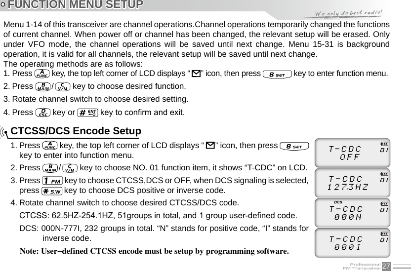
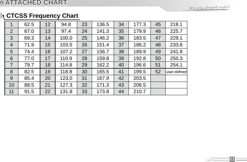
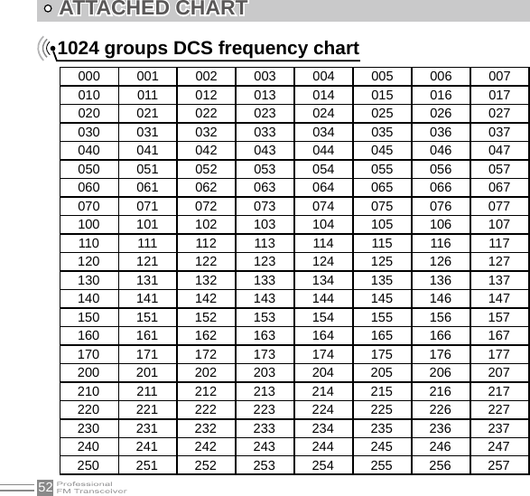
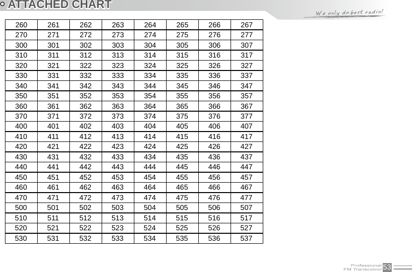
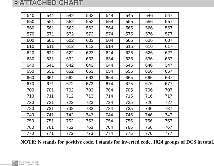
![293. Press key to choose CTCSS,DCS or OFF, when DCS signaling is selected, press key to choose DCS positive or inverse code.4. Rotate channel switch to choose desired CTCSS/DCSencode/decode.CTCSS: 62.5HZ~254.1HZ, 51groups in total, and 1 group user-dened code.DCS: 000N-777I, 232 groups in total. “N” stands for positive code, “I” stands for inverse code.5. Press or key to conrm and exit.FUNCTION MENU SETUP5TONE encode must be programmed by software, only the groups with editing 5TONE can be selected. When 5TONE encode is editing with name, transceiver will display name, otherwise will display “ CALL XX ”. Default configuration is 5TONE, 2TONE can be customized according to different market requirements.5TONE/2TONE encode group selection1. Press key, the top left corner of LCD displays “ ” icon, then press key to enter into function menu.2. Press / key to choose NO. 04 function item, it shows “5T-ENC”/”2T-ENC” on LCD.3. Rotate channel switch to choose desired 5TONE encode group.CALL00~CALL99, 100 groups in total for optional.4. Press [PTT] key to transmit selected 5TONE encode, press key or key to conrm and exit.](https://usermanual.wiki/Qixiang-Electron-Science-and-Technology/QZQX3318/User-Guide-2261952-Page-37.png)
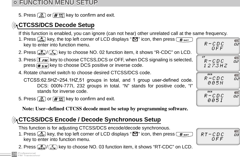
![35FUNCTION MENU SETUPBUSY: Carrier wave lock, transmitting is prohibited when received matching carrier wave.REPEAT: Signaling lock, transmitting is prohibited when received matching carrier but with unmatching CTCSS/DCS.OFF: Close BCLO function.4. Press key or key to conrm and exit.TX OFFWhen this function is on, [PTT] key is unavailable. Current channel of transceiver only works under receiving mode.1. Press key, the top left corner of LCD displays “ ” icon, then press key enter into function menu.2. Press / key to choose NO. 14 function item, it shows “TX” on LCD.3. Rotate channel switch to choose desired setup.ON: TX OFF is enabled.OFF: TX OFF is disabled.4. Press key or key to conrm and exit.Band LimitWhen this function is on, inputting frequency or Scanning frequency under VFO is limited in current VFO frequency band.](https://usermanual.wiki/Qixiang-Electron-Science-and-Technology/QZQX3318/User-Guide-2261952-Page-43.png)
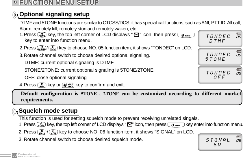
![38Voice Operated Transmission (VOX) SetupWhen this function is on, the transmitting can be started by voice, no need to press [PTT] key.1. Press key, the top left corner of LCD displays “ ” icon, then press key enter into function menu.2. Press / key to choose NO. 19 function item, it shows “VOX” on LCD.3. Rotate channel switch to choose desired setup.1~10 : Total 10 VOX levels for optional. OFF: VOX function is disabled.4. Press key or key to conrm and exit.VOX Delay SetupIf transceiver returns to receive mode instantly after VOX calling, it may cause calling voice missing. To avoid this problem, user can set a suitable delay time.1. Press key, the top left corner of LCD displays “ ” icon, then press key enter into function menu.2. Press / key to choose NO. 20 function item, it shows “VDELAY” on LCD.3. Rotate channel switch to choose desired setup.0.5S-3S: Total 27 levels for optional, each interval is 0.1S4. Press key or key to conrm and exit.FUNCTION MENU SETUP](https://usermanual.wiki/Qixiang-Electron-Science-and-Technology/QZQX3318/User-Guide-2261952-Page-46.png)
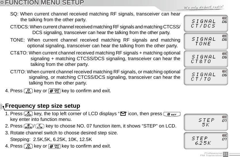
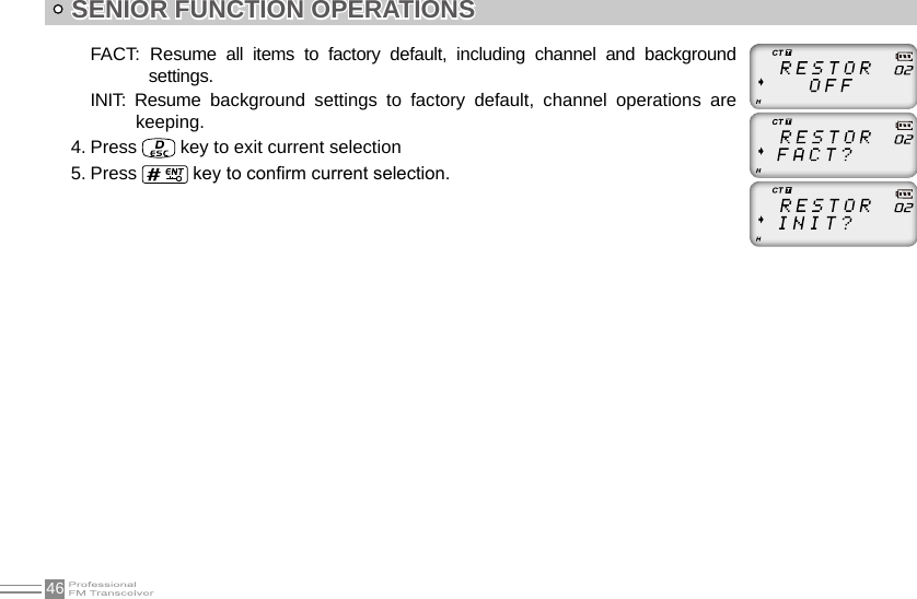
![45SENIOR FUNCTION OPERATIONSDisplay Mode SetupThere are three kinds of display modes for optional.1. Press [PF2] key to turn on radio, hold [PF2] key until transceiver emits beep.2. Press / key to choose No. 01 function item, it shows “DSP” on LCD.3. Rotate channel switch to choose desired setup.FREQ: Frequency + Channel mode, transceiver displays current channel name + frequency, press key to switch into VFO mode.CH: Channel mode, 1~21 items of function menu will hide automatically, user can only operate some functions. It is unable to switch into VFO by pressing key. This model can be used for Amateur mode.NAME: Channel + Name Tag mode, transceiver displays current channel number + channel name, press key to switch into VFO mode.4. Press key or key to conrm and exit.Resume Factory DefaultYou can make all the settings of transceiver return to the factory default settings when transceiver can not work normally because of wrong operation or error setup.1. Press [PF2] key to turn on radio, hold [PF2] key until transceiver emits beep.2. Press / key to choose No. 02 function item, it shows “RESTOR” on LCD.3. Rotate channel switch to choose desired setup.OFF: No operations.](https://usermanual.wiki/Qixiang-Electron-Science-and-Technology/QZQX3318/User-Guide-2261952-Page-53.png)
![50Can not power on or frequent power off Check weather the battery touch is out of sharp or broken.The receiving sound gets low or intermittentCheck weather the MIC is stoppage. Otherwise, please contact with local dealers to repair it.Receiving intermittent with in big noiseA.Out of communication range or obstruct by tall buildings or in big noise.B.450 filter is broken, Please contact with local dealers to repair.Loudspeaker become lower or with“ka ka”sound after using a certain timeCheck whether the loudspeaker is broken, Iron powder or sundries is in the loudspeaker. Please contact with local dealers to repair.Receive voice from the other party but can not transmit Check [PTT] key.Receiving indicator with green light but no soundA.Low volume, please clockwise to turn on.B.Loudspeaker is broken, please contact with local dealers to repair.C.Earphone jack is broken, please contact with local dealers to repair.D.Volume switch is broken.TROUBLE SHOOTING GUIDE](https://usermanual.wiki/Qixiang-Electron-Science-and-Technology/QZQX3318/User-Guide-2261952-Page-58.png)