Qixiang Electron Science and Technology QZQX3318 Two Way Radio User Manual
Qixiang Electron Science& Technology Co., Ltd Two Way Radio
user manual

A1.0-12/07
A1.0-13/03
DUAL BAND HANDHELD RADIO
INSTRUCTION MANUAL
TWO WAY RADIO
FCC ID:T4K-QZQX3318
THANK YOU!
transceiver introduces innovative DSP digital signal processing technology, high degree integration, it is
including kinds of professional function, best stability and great reliability as well as exterior smooth lines,
novel, fashionable, sturdy and durable.
The transceiver is including plenty of TX, RX channels, as well as UU,VV and UV standby modes which
is able to realize cross band function (Version C), 51 groups of CTCSS encode/decode and 1 group of
user-defined CTCSS encode/decode, 1024 groups of DCS encode/decode, 5TONE/2TONE encode/
decode(optional), DTMF encode/decode, built-in FM radio functions, etc..
It is a meticulous build functional and Multi frequency band radio for radio amateur.
Versions
To meet different requirements of users, we provide A,B,C,D four versions with different frequency bands,
convenient for user optional.
Version A: Dual frequency, dual standby, dual display, dual band, single receive channel.
Version B: Dual frequency, dual standby, dual display, tri band, 350-390MHz is able to combine with UHF or
VHF be dual frequency to receive signal at same time.
Version C: Dual frequency, dual standby, dual display, dual band, dual receive channel, main band and sub
band can receive signal at same time.
Version D: Dual frequency, dual standby, dual display, multi band, dual receive channel, air band and
4 band FM.
MODELS APPLY TO THIS MANUAL
PROGRAM CAUTIONS
When programming the transceiver, read the factory initial data first, then rewrite the frequency and
signaling etc., other wise errors may occur because of different frequency band etc.
transceiver will provide you with reliable, clear and efficient communication service. The
The
3318UV FM transceiver
3318UV(Version A,C,D) programming software: QPS3318UV
3318UV(Version B) programming software: QPS3318UV_B

CAUTIONS
performing your obligation under warranty and understanding the safety of transceiver usage.
1.Keep the transceiver and accessories away from children.
2.Please do not try to open or modify the transceiver without permission, non-professionals operation may also cause
damage.
3.Please use assorted battery and charger to avoid damage.
4.Please use assorted antenna to ensure the communication distance.
5.Please avoid exposing the radio under the sunshine for a long time or storing it in too hot places. High temperature will
shorten the life of electronic devices.
6.Please avoid storing the radio in the dusty, dirty and damp areas.
7.Please keep the radio dry. Do not wash radio with ardent chemicals and detergents.
8.Do not transmit without antenna.
9.When using this transceiver, we recommend transmitting for 1 minute then receiving for 4 minutes. continuously
transmitting for long time or working in high power will heat the back of the transceiver. Do not place the transceiver's hot
back close to any plastics.
10.If any abnormal smell or smoke coming from the transceiver, please turn off the power instantly and take off the battery
and its case. Then contact local
dealers.
NOTE:
All the above tips apply for your
transceivers' accessories. If any device can not operate
normally, please contact with local
dealers.
If you use any accessories made by other companies,
company does not guarantee the
operability and safety of the transceiver.
transceiver is excellent designed with advanced technology. The following tips will be helpful for you in
The

I
TABLE OF CONTENTS
UNPACKING ................................................................................................................................................................................................01
Supplied Accessories .........................................................................................................................................................................01
STANDARD ACCESSORIES/ADDITIONAL ACCESSORIES ...............................................................................02
Standard Accessories ..........................................................................................................................................................................02
Additional Accessories ........................................................................................................................................................................ 02
OPERATION MODE (AMATEUR TRANSCEIVER OR PROFESSIONAL TRANSCEIVER) .........03
WORKING MODE (AMATEUR TRANSCEIVER OR PROFESSIONAL TRANSCEIVER) ..............04
BATTERY INFORMATION .................................................................................................................................................................05
Charging Operation ..............................................................................................................................................................................05
Battery Charger Type........................................................................................................................................................................... 05
Notice for Charging Battery ..............................................................................................................................................................05
How to Charge ........................................................................................................................................................................................06
Charging Prompt ....................................................................................................................................................................................08
How to Store the Battery ....................................................................................................................................................................08
INSTALLATION & CONNECTION ...............................................................................................................................................09
Installing / Removing the Li-ion Battery ......................................................................................................................................09
Installing / Removing the Antenna................................................................................................................................................. 10
Installing / Removing the Belt Clip ................................................................................................................................................ 10
Installing Optional Speaker / Microphone .................................................................................................................................. 11
GETTING ACQUAINTED ...................................................................................................................................................................12
LCD Display .............................................................................................................................................................................................12
BASIC OPERATIONS ...........................................................................................................................................................................15
Turn the Radio On & OFF .................................................................................................................................................................15
Adjusting Volume ...................................................................................................................................................................................15

II
TABLE OF CONTENTS
Switch between Main band and Sub band ...............................................................................................................................16
Switch between Channel mode and VFO mode ....................................................................................................................16
Channel Adjusting ................................................................................................................................................................................. 16
Frequency Adjusting .............................................................................................................................................................................16
Frequency Input by Keypad .............................................................................................................................................................17
Channel Input by Keypad .................................................................................................................................................................. 17
FM Channel Searching .......................................................................................................................................................................18
Squelch Off Momentary / Squelch Off .........................................................................................................................................18
Receiving ...................................................................................................................................................................................................18
Transmitting ..............................................................................................................................................................................................19
Emergency Alarm ..................................................................................................................................................................................19
Side Key [PF1] function instruction ...............................................................................................................................................19
Side key [PF2] function instruction................................................................................................................................................20
Edit channel ..............................................................................................................................................................................................20
Delete channel ........................................................................................................................................................................................21
Programming scan ................................................................................................................................................................................21
SHORTCUT OPERATIONS ..............................................................................................................................................................22
Turn On/ Off FM Radio........................................................................................................................................................................ 22
Add/Cancel Optional signal decode function ...........................................................................................................................22
CTCSS/DCS Scan ................................................................................................................................................................................23
Offset Frequency Direction Setup ................................................................................................................................................. 23
Frequency/Channel Scan .................................................................................................................................................................. 24
Channel Scan Skip ...............................................................................................................................................................................24
Frequency Reverse ..............................................................................................................................................................................25
TX Power selection ...............................................................................................................................................................................25

III
TABLE OF CONTENTS
Stopwatch function................................................................................................................................................................................25
DTMF code Transmit and Enquiry ................................................................................................................................................26
Keypad lock .............................................................................................................................................................................................. 26
Function Menu Setup ..........................................................................................................................................................................27
CTCSS/DCS Encode Setup ............................................................................................................................................................. 27
CTCSS/DCS Decode Setup .............................................................................................................................................................28
CTCSS/DCS Encode / Decode Synchronous Setup ...........................................................................................................28
5TONE/2TONE encode group selection ....................................................................................................................................29
Optional signaling setup ..................................................................................................................................................................... 30
Squelch mode setup ............................................................................................................................................................................ 30
Frequency step size setup ................................................................................................................................................................31
Wide / Narrow Band Selection .......................................................................................................................................................32
Frequency Reverse ..............................................................................................................................................................................32
Talk Around ON/OFF............................................................................................................................................................................33
Offset Frequency setup ...................................................................................................................................................................... 33
Editing Channel name ......................................................................................................................................................................... 34
Busy Channel Lockout ........................................................................................................................................................................34
TX OFF .......................................................................................................................................................................................................35
Band Limit .................................................................................................................................................................................................35
Sub band display setup ...................................................................................................................................................................... 36
Keypad Voice prompt setup ............................................................................................................................................................. 37
Time-Out-Timer (TOT)......................................................................................................................................................................... 37
Voice Operated Transmission (VOX) Setup ............................................................................................................................. 38
VOX Delay Setup .................................................................................................................................................................................. 38
Automatic Power Off Time setup ...................................................................................................................................................39

IV
TABLE OF CONTENTS
DTMF Transmitting Time Setup ......................................................................................................................................................39
Squelch level setup .............................................................................................................................................................................. 40
Scan Dwell Time Setup ......................................................................................................................................................................40
Function Icon Stay Time Setup .......................................................................................................................................................41
LCD Backlight Setup ............................................................................................................................................................................41
LCD Backlight Color Setup ...............................................................................................................................................................42
Self ID inquiry ..........................................................................................................................................................................................42
Tone Pulse Frequency Selection ...................................................................................................................................................43
Battery Save Setup ...............................................................................................................................................................................43
FM radio .....................................................................................................................................................................................................44
Senior Function Operations .........................................................................................................................................................45
Display Mode Setup .............................................................................................................................................................................45
Resume Factory Default .................................................................................................................................................................... 45
Programming software starting (Takes Windows XP system for example) ....................................... 47
TECHNICAL SPECIFICATION .......................................................................................................................................................48
TROUBLE SHOOTING GUIDE ......................................................................................................................................................49
ATTACHED CHART ............................................................................................................................................................................... 51
CTCSS Frequency Chart ...................................................................................................................................................................51
1024 groups DCS frequency chart ...............................................................................................................................................52
01
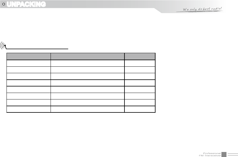
UNPACKING
Please carefully unpack the transceiver. We recommend that you identify the items listed in the following
table before discarding the packing material.
If any items are missing or have been damaged during shipment, please contact with dealers
immediately.
Supplied Accessories
Item Number Quantity
Antenna QA09UV2 1
Li-ion Battery QB-26L 1
Battery Charger QBC-26L 1
AC Adaptor QPS-01 1
Belt Clip BC01 1
Hand Strap GS01 1
Instruction Manual 1
Certicate 1
02
STANDARD ACCESSORIES/ADDITIONAL ACCESSORIES
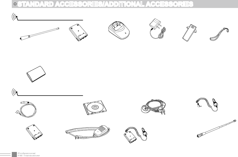
Standard Accessories
Additional Accessories
Antenna*1
QA09UV2
145/435MHz
*1.Note: For frequency band of antenna, please refer to label
indicated in the bottom of the antenna.
Li-ion Battery
QB-26L(1500mAh)
Spare Li-ion Battery
QB-26HL(1500mAh)
Instruction
Manual
USB Programming
Cable PC03
Programming
Software
QPS3318UV
Earphone
HS03
Handheld Microphone
QHM22
Battery Charger
QBC-26L
AC Adaptor
(12V/500mA)
QPS-01
Belt Clip
BC01
Battery Pack
for Car Charger
CPS01 Telescopic antenna
QA10UV
Car
Charger
CPL03
Hand Strap
GS01
03
The transceiver is a high performance amateur transceiver with dual band, dual standby, dual display and other
kinds of functions. According to practical application,you can set the radio operates as Amateur Transceiver
or Professional Transceiver. There are also 3 levels operation menu to set functions as per you need. It is
easy and convenient.
Operation Mode:
1.
By programming software:A. In PC software's "General Setting"menu to
choose "Display Mode" , channel mode works as Professional transceiver
,other two modes as Amateur transceiver.
By manual setup:B. Please refer to "Display Mode" in Page 45.
Amateur Transceiver Mode:
2. Except setting as CH mode, others considered as Amateur
transceiver mode. Under this mode,press key to switch between Channel mode
and VFO.
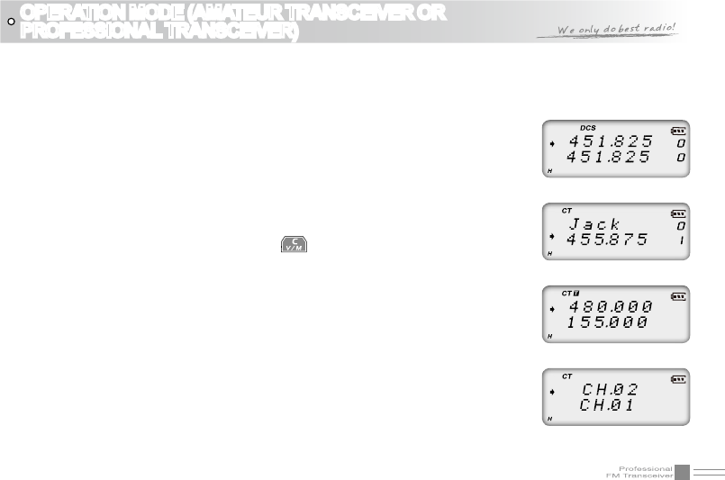
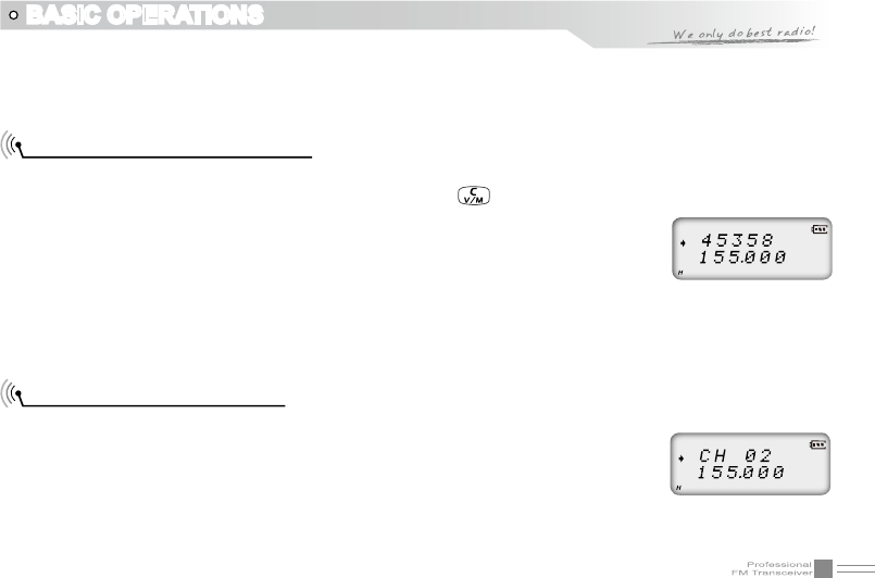
Frequency + Channel mode: A. At this mode, When set display as"FREQ",it
enters into Frequency+Channel mode, new setting of channel operation and
shortcut operation can be temporarily used by user. Once the radio is turned
off or switched to another channel, the temporary setting will be erased and
back to initial settings.(As pic 1)
Channel+Name Tag Mode:B. When set display as "NAME",it enters into
Channel +Name Tag Mode. At this mode, it will display corresponding
channel name when the current channel is edited with name. Otherwise, it
will display frequency + channel. Its operations are the same as frequency +
channel mode. (As pic 2)
OPERATION MODE (AMATEUR TRANSCEIVER OR
PROFESSIONAL TRANSCEIVER)
(Pic 1)
(Pic 2)
(Pic 3)
(Pic 4)
04
WORKING MODE (AMATEUR TRANSCEIVER OR PROFESSIONAL TRANSCEIVER)
VFO Mode(Frequency mode): C. This mode shows only frequency on the display. Shortcut operation
and Channel setting will be changed & stored as the latest value permanently. Once the radio is
turned off or changed to new VFO frequency, the value is remained until next change.(As pic 3)
Professional Transceiver Mode:
3. When set display mode as "CH",it enters into Professional Transceiver mode.At this
mode,except scan,DTMF encode or editing, and keypad lock,other functions should be set by PC software (As pic 4).
NOTE:If transceiver programmed transceiver as professional mode and locked,you can't return to amateur
transceiver mode by manually from Background operations setting.
Under every mode, background operations can be changed and saved.
4.
05
BATTERY INFORMATION
Charging Operation
The battery is not charged at the factory, please charge it before use. Charge the battery for the rst time
after purchase or extended storage (more than 2 months) may not bring the battery to its normal operating
capacity. After repeating fully charge/ discharge cycle for two or three times, the operating capacity will
reach the best performance. The battery life is over when its operating time decreases even though it is
fully and correctly charged. Replace the battery.
Battery Charger Type
Please use our company's designated charger, other models may cause explosion and injure people. After
installing the battery, if the radio red light twinkles and remind changing battery, please charge the battery.
Notice for Charging Battery
Do not shortcircuit our company designated charger. Never attempt to remove the casing from the ▲
battery, we show no responsibility on the faulty caused by modifying freely without permission of our
factory.
The ambient temperature should be between 5 ▲℃ and 40℃ in charging. Charging outside this range
may not fully charge the battery.
Always switch off the transceiver equipped with a battery before charging. Otherwise, it will interfere ▲
with correct charging.
To avoid interfering the charging procedure, please do not cut off the power or take out the battery ▲
during charging.
06
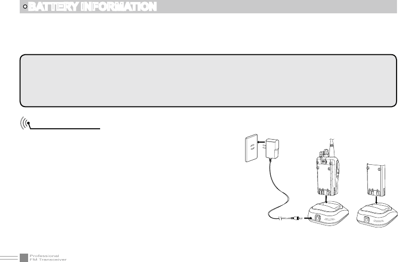
How to Charge
1.Plug the AC adaptor into the AC outlet, then plug the
cable of AC adaptor into the DC jack, the indicator
lights orange for 1s and turns into GREEN---waits to
charge.
2.Slide the battery or transceiver with battery into
the charger; make sure the battery terminals are in
contact with the charging terminals well. LED turns
into twinkling RED ---pre-charging begins.
3.Pre-charging for about 5 minutes, LED twinkles stop
then charging begins.
4.It takes about 4 hours to fully charge the battery, when
LED turns into GREEN— full charged
BATTERY INFORMATION
WARNING:
When keys or ornamental chains and other electric metals contact with the battery terminals, the battery
may cause damage or hurt bodies. If the battery terminal short circuit, it will generate a lot of heat, please
be careful when you bring or use the battery, please put battery or radio into insulated container. Do not put
it into metal container.
Do not recharge the battery if it is already fully charged. This may shorten the life of the battery or ▲
damage the battery.
Do not charge the battery or transceiver if it is damp. Dry it before charging to avoid danger. ▲
Ac Input
07
NOTE: When charging a power-on transceiver equipped with battery, the LED will not turn into green to
show the full charge status. Only when turn off the transceiver, the LED can indicate normally.
Because when the transceiver is power on, it would consumes energy, the charger cannot detect when battery
has been fully charged, the charger will charge battery in voltage consumption and fail to indicate correctly.
BATTERY INFORMATION
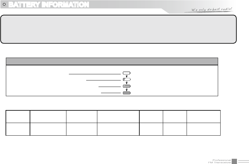
Status LED
STATUS self-examine
when power on (No battery) Pre-charging Charge
normally Full
Charged Trouble
LED Orange
(for 1 second) Green Red light twinkles
for 5 minutes Red Green Red twinkles
for a long time
5.Charging Process:
6.LED Indicator:
NOTE: Trouble means battery heating, battery short-circuit or charger short-circuit.
Standby (self-examine orange lights
1second when power on)
Pre-charging (pre-charging stage)
Charging (charge in constant currency)
Full charged (charge in constant voltage)
Green light
Red light twinkles for about 5 minutes
RED light lightens for about 4 hours
Green light
08
How to Store the Battery
1.If the battery needs to be stored, the
battery should be kept in the status of
50% discharge.
2.It should be kept in low temperature,dry
environment.
3.To keep away from hot places and direct
sunlight.
Charging Prompt
1.Self- examination: When charging, ORANGE light twinkles for 1 second and goes out. That means the
charger has passed its self-examination and it can charge the battery normally. If the light remains
orange or the red light twinkles, which means the charger can not pass its self-examination or charge
the battery.
2.Trickle pre-charging: when the battery has been inserted into the charger and red light twinkles, which
means the remnant voltage is low, the charger trickle charge the battery (pre-charging status ), until the
battery reaches a certain electric quantity, the charger automatically turns into normal charging. And
if the red light stop twinkling, which means the remnant voltage meets a certain electric quantity, the
charger will charge the battery normally.
BATTERY INFORMATION
NOTE:The time for Trickle pre-charging is not exceed 30m.After 30m,the red indicator is still twinkling,it
means it is unable to charge battery. Please kindly check battery and charger.
WARNING
▲Do not short circuit battery terminals.
▲Never attempt to remove the casing from the battery
pack.
▲Never assemble the battery in dangerous surroundings,
spark may cause explosion.
▲Do not put the battery in hot environment or throw it
into fire, it may also cause explosion.
09
INSTALLATION & CONNECTION
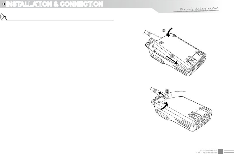
1.Match the three grooves of the battery pack with the
corresponding guides on the back of the transceiver and
push.
2.Press the battery pack and transceiver rmly together
until the release latch on the top of the transceiver locks.
After hearing a "click" sounds, the battery has been
locked.
3.To remove the battery pack, slide up the release latch
and remove the pack away from the transceiver.
Installing / Removing the Li-ion Battery
10
INSTALLATION & CONNECTION
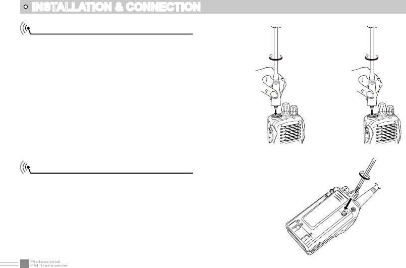
Installing / Removing the Antenna
■ Installing the Antenna:
Screw the antenna into the connector on the top of
the transceiver by holding the antenna base and
turning it clockwise until secure.
■ Removing the Antenna:
Turn the antenna anticlockwise to remove it.
Installing / Removing the Belt Clip
■ Installing the Belt Clip:
Place the belt clip to the corresponding grooves
on the back of the transceiver, and then Clockwise
screw it.
■ Removing the Belt Clip:
Anticlockwise turn screws to remove the belt clip.
11
INSTALLATION & CONNECTION
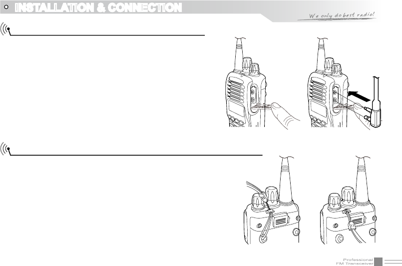
Installing Optional Speaker / Microphone
■ Installing the Antenna:
Screw the antenna into the connector on the top of
the transceiver by holding the antenna at its base
and turning it clockwise until secure.
■ Removing the Antenna:
Anticlockwise turn the antenna to remove it.
Installing / Removing the Belt ClipInstalling the Antenna
■ Installing the Belt Clip:
Place the belt clip to the corresponding grooves on the
back of the transceiver, and then clockwise screw it.
■ Removing the Belt Clip:
Anticlockwise turn screws to remove the belt clip.
12
GETTING ACQUAINTED
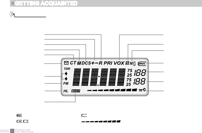
LCD Display
On LCD display screen, you will see various icons which stand for the selected functions and sometimes
you may forget the meaning of them. Here you will nd the following table extremely useful.
Frequency
Reverse
Offset Frequency
DCS
Optional Signaling
CTCSS
FUNC Icon
The arrow points to
main channel
FM radio
TX Power
Busy Channel
VOX Function
Scan Skip
Narrow band
Battery Capacity
Function Menu
Number, Channel
Number
FM Channel Number
channel Number
Keypad Lock
NOTE:
Battery capacity indicator(full) No power,replace battery pack or charge battery
Real time display receiving signal
strength/Power Indicator
Battery capacity remnant
13
GETTING ACQUAINTED
1
3
2
7
4
8
5
9
6
10

14
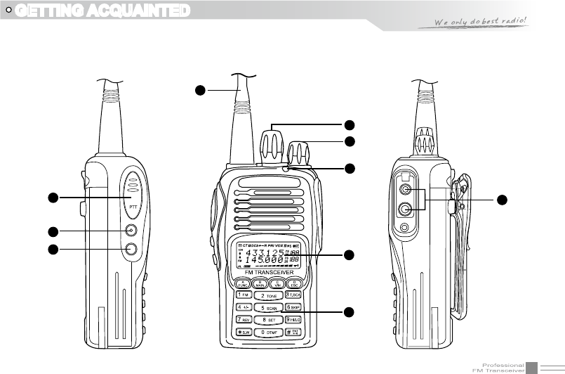
GETTING ACQUAINTED
1 Antenna
2 Selector Knob
3 Power / Volume switch
Rotate it clockwise to turn on transceiver, rotate it anticlockwise until heard "click" to turn off the
transceiver.
When transceiver is power on, rotate it clockwise to increase volume, anticlockwise to reduce volume.
4 TX/RX indicator, RX is GREEN, TX is RED
5 LCD display
Displays current frequency/channel and operations
6 Keypad
Enters desired frequency/channel or operations by keypad
7 PTT key
Press PTT key to talk, release this key to receive.
8 PF1 key
9 PF2 key
10 Speaker/Microphone jack, programming software jack
15
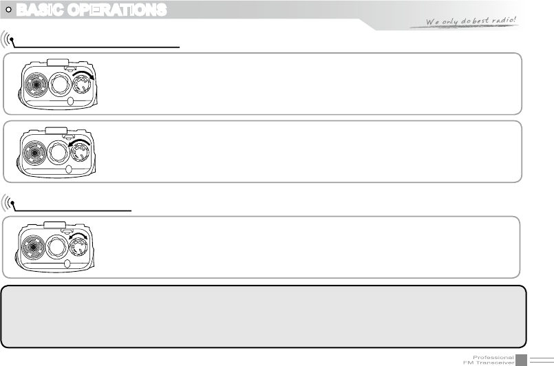
Turn the Radio On & OFF
NOTE:
Press the side key programmed as Squelch Off Momentary to monitor the background noise. Turn [POWER]/
[VOLUME] to control the volume.The volume you need can be adjusted more correctly when communicating
with the other party.
BASIC OPERATIONS
Under power-off state, please turn [POWER]/ [VOLUME] clockwise to turn on the
transceiver.
Under power-on state, please turn [POWER]/ [VOLUME] anticlockwise to turn off
the transceiver.
Under power-on state, turn [POWER] / [VOLUME] to adjust volume. Clockwise-
up, anticlockwise -down.
When adjusting the volume, user can press the key programmed as Squelch Off
to monitor current volume rstly.
Adjusting Volume
16
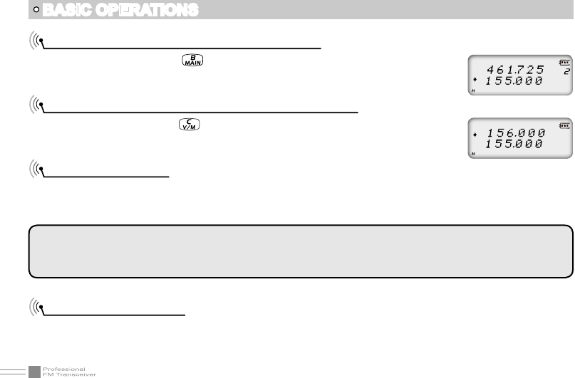
Switch between Main band and Sub band
Under standby state, press key to switch channel between Main band and Sub
band. Arrow directs the current operational channel.
Switch between Channel mode and VFO mode
Under standby state, press key to set main band as Channel mode or frequency
mode(VFO).
Channel Adjusting
When transceiver in Channel mode or FM radio channel mode, rotate channel switch to adjust channel.
Rotate channel switch clockwise to enter the downward channel, anticlockwise to enter the upward
channel.
Frequency Adjusting
When transceiver in VFO mode or FM radio frequency mode, rotate channel switch to adjust frequency.
Rotate channel switch clockwise to increase frequency, anticlockwise to decrease frequency. Every rotate
can add or reduce one stepping value.
NOTE: In transceiver mode, arrow directs the main band channel.
If there is a null channel between two channels, transceiver will skip null channel, enter into next channel
directly.
BASIC OPERATIONS
17
BASIC OPERATIONS
Frequency Input by Keypad
Under frequency mode or FM radio frequency mode, you can directly enter frequency through keypad.
1. When your transceiver is under Channel mode, press key to switch into VFO.
NOTE: When the transceiver is under Channel mode, it shows current channel
number on the right of main frequency.
2.Enter the desired frequency by keypad.
NOTE: The frequency input of main channel or FM radio is relevant to the stepping
and transceiver frequency range. If frequency setup is beyond range or not matching with step size, the
input is unavailable. Under the FM radio mode, the frequency step size input by numeric keys is 100k.
Channel Input by Keypad
Under channel mode of transceiver or FM radio, you can switch to desired channel
by entering three numbers (001-199). If the entered channel is not in edited channel
range, the transceiver will emit beep to prompt wrong input and return to current
channel. For example, entering 001 is channel 1, 030 is channel 30, 125 is channel
125.
18
BASIC OPERATIONS
FM Channel Searching
When transceiver in FM radio mode, press key, LCD displays FUNC icon, then
press to start FM searching. When one station is sought, LCD displays
current station frequency, you can listen to current station.
Squelch Off Momentary / Squelch Off
Side key [PF2] can be setup for Squelch off Momentary or Squelch off function by programming software.
1.Squelch off: Press [PF2] key, squelch circuit is not mute, back-ground noise can be heard. Press [PF2]
key again, squelch circuit is mute.
2.Squelch off Momentary: Press and hold [PF2] key, squelch circuit is not mute, back-ground noise can be
heard. Release [PF2] key, squelch circuit is mute.
NOTE: The above functions are only available after [PF2] key setup in programming software.
Receiving
When your transceiver is called by other party, the green LED light will be on and the arrow icon will ash,
you can hear the calling.
NOTE: You may not receive the calling when your transceiver is set at high squelch level. If current channel
is programmed with decode signal, only the same signaling call can be heard .
19
BASIC OPERATIONS
Transmitting
According to [PF2] key setup in programming software, hold [PF2] key to monitor the channel to ensure it
is not busy, press PTT key and talk to speaker.
Please keep the distance between mouse and speaker to be 2.5-5CM, speak in normal tone to get the
best acoustic delity.
NOTE: When press and hold PTT key, transceiver is transmitting if the red LED light is on, release PTT key
to receive calls.
Emergency Alarm
Under standby state, press and hold alarm key until LCD displays “ALARM”, Emergency alarm function is
started. This transceiver has 4 Alarm modes for optional, can be setup in programming software. Power
off transceiver to exit Alarm.
Side Key [PF1] function instruction
1. Battery capacity inquiry: Under standby, press [PF1] key, LCD displays current battery capacity, press
this key again to exit.
2. Transmit tone pulse frequency: Press and hold PTT key, then press [PF1] key to transmit selected tone
pulse frequency.
NOTE: The tone pulse frequency can be set to 1750Hz, 1450Hz, 1000Hz or 2100Hz in programming software.
20
BASIC OPERATIONS
Side key [PF2] function instruction
1. Squelch off: Press [PF2] key, squelch circuit is not mute, back-ground noise can be heard. Press [PF2]
key again, squelch circuit is mute.
2. Squelch off Momentary: Press and hold [PF2] key, squelch circuit is not mute, back-ground noise can
be heard. Release [PF2] key, squelch circuit is mute.
3. Transmit DTMF/5TONE signaling: Press and hold [PTT] key, then press [PF2] key to transmit selected
DTMF/5TONE signaling.
NOTE: The optional signaling of current channel is DTMF or no optional signaling, the operation will transmit
DTMF signaling, otherwise will transmit 5TONE signaling.
4. Press and hold [PF2] key to turn on transceiver, until transceiver emits “DU” beep, transceiver enter into
general functions setup.
Edit channel
1. Under frequency mode (VFO), enter desired frequency and settings, press key, the top left corner
of LCD displays “ ” icon, press key to switch into channel mode, channel number ashes.
2. Rotate channel switch to select desired editing channel number.
3. Press key, the top left corner of LCD displays “ ” icon, press and hold key until transceiver
emits “DUDU” beep, channel is stored successfully.
21
BASIC OPERATIONS
Delete channel
1. Under standby state, press key, the top left corner of LCD displays “ ” icon, press key to
switch into channel mode, channel number ashes.
2. Rotate channel switch to select desired deleting channel number.
3. Press key, the top left corner of LCD displays “ ” icon, press and hold key until transceiver
emits “DUDU” beep and clear up frequency information of current channel, deletion is successful.
NOTE: This process can be applied for deleting FM radio channels.
Programming scan
Setup the frequency of L1 channel, U1 channel, L2 channel and U2 channel will realize VFO frequency
scanning border limited. L1 & L2 is starting frequency, U1 & U2 is end frequency. When VFO frequency
between L1~ U1 or L2 ~ U2, transceiver will scan frequencies between L1 ~ U1 or L2 ~ U2. When VFO
frequency is lower than L1 or L2, transceiver will scan frequencies higher than L1 or L2. When VFO
frequency is lower than U1 or U2, transceiver will scan frequencies higher than U1 or U2.
1. In VFO mode, enter desired frequency and relative setup, press key, the top left corner of LCD
displays “ ” icon, then press key switch into channel mode, channel number ashes
2. Rotate channel switch to choose desired channel number.
3. Press key, the top left corner of LCD displays “ ” icon, then press key until transceiver emits
“DUDU” beep, channels are saved successfully.
NOTE: To make this setup, L1 and U1 must in same frequency band, L1 must lower than U1. L2 and U2
must in same frequency band, L2 must lower than U2.
22
SHORTCUT OPERATIONS
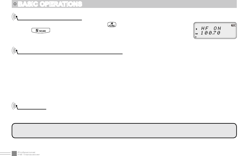
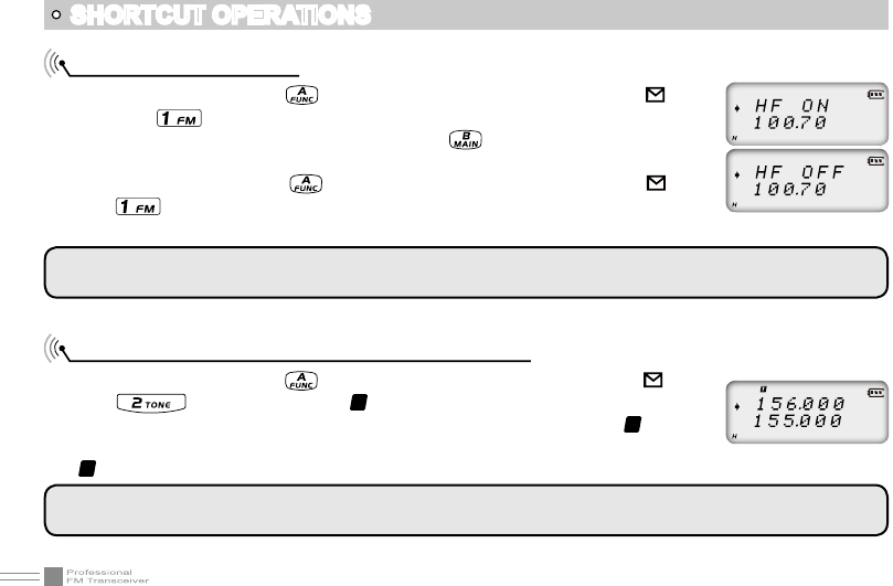
Turn On/ Off FM Radio
Under standby state, press key, the top left corner of LCD displays “ ” icon,
then press key, LCD displays “HF ON” and current FM radio frequency, FM
radio function is on. When FM radio is on, press key, LCD displays “HF OFF”,
FM radio is mute.
When FM radio is on, press key, the top left corner of LCD displays “ ” icon,
press key to turn off FM radio and return to transceiver state.
NOTE: To use FM radio function, user must set RADIO function on 31th menu to be ON, otherwise can not
use FM radio function normally.
Add/Cancel Optional signal decode function
Under standby state, press key, the top left corner of LCD displays “ ” icon,
press key, LCD displays “
T
” icon, it means current channel add DTMF
signal decode function. Repeat above operation, LCD still displays “
T
“ icon, it
means current channel add 5TONE signal decode function. Repeat above operation,
“
T
” icon disappears, optional signal decode function is cancelled.
NOTE: When this function is on, user must setup 11th menu to be TONE option, then DTMF/5TONE can be
used.
NOTE: Re-start transceiver also can exit FM radio function.
23
SHORTCUT OPERATIONS
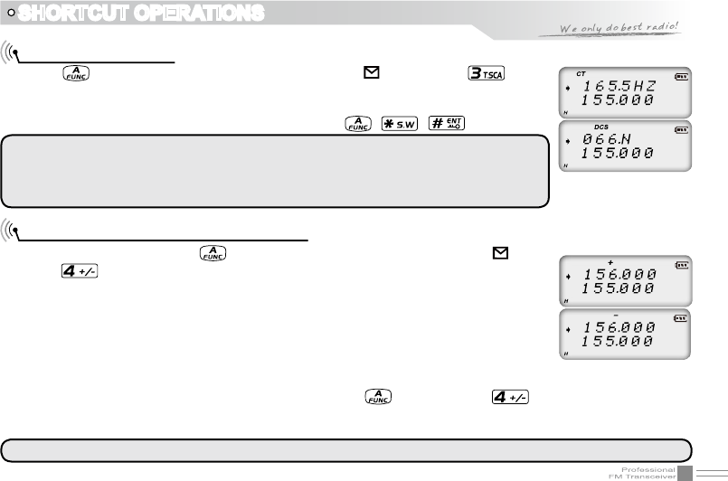
CTCSS/DCS Scan
Press key, the top left corner of LCD displays “ ” icon, press key to
enter into CTCSS/DCS scan. Under this state, rotate channel switch to change scan
direction. When scan the matching CTCSS/DCS signaling, it will stay 5seconds and
then go on scanning. Press any other keys except , , key to exit.
NOTE: This function is invalid when transceiver works in professional mode or the
arrow directed channel no setting CTCSS/DCS signaling.
In current channel, if signaling set as CTCSS, it will scan CTCSS, if sets as DCS, will
scan DCS.
Offset Frequency Direction Setup
Under standby state, press key, the top left corner of LCD displays “ ” icon,
press key to choose offset frequency direction. There are 3 options, Positive
offset, Minus offset, shut off offset.
1. (+) Positive offset: Indicates TX frequency is higher than RX frequency. When
enable reverse function, the RX frequency is higher than TX frequency.
2. (-) Minus offset: Indicates TX frequency is lower than RX frequency. When enable
reverse function, the RX frequency is lower than TX frequency.
3. None: Indicates shut offset off.
Under frequency mode (VFO) or channel mode, press key then press key to choose positive
offset direction(+), minus offset direction (-) , shut offset off one by one (Please refer to offset frequency
setup).
NOTE: This function is unavailable in professional transceiver mode.
24
SHORTCUT OPERATIONS
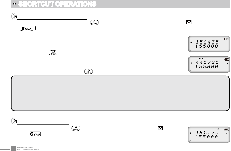
Frequency/Channel Scan
Under corresponding mode, press key, the top left corner of LCD displays “ ” icon, then press
key to start frequency scan or channel scan.
1. Frequency Scan
Under VFO mode, frequency scan is available. This function is used for monitoring
signal of various communication frequency by transceiver ‘step’ setup, press
numeric key or key to exit.
2. Channel Scan
Under channel mode, this function is used for monitoring signal of each channel in
this mode. Press numeric key or key to exit.
NOTE:
Frequency scan is of all bands scan, it scans upwards as your STEPPING setting.
In channel scan, the skipped channel is not in the line of scanning. Scan upwards as per channel no.
(please refer to channel scan skip).
Frequency/channel scan can change scan direction by rotating channel switch, when find a matching carrier
wave and signaling, the transceiver will stay 5 seconds then go on scanning. (Please refer to scan setup)
Channel Scan Skip
Under channel mode, press key, the top left corner of LCD displays “ ” icon, then
press key to set current arrow directed channel as Channel scan skip. Repeat above
operation to cancel channel scan skip.
▼
▼
▼
25
SHORTCUT OPERATIONS
1. LCD displayed “
S
” means the current channel will not be scanned.
2. “
S
” icon disappeared means the current channel will be scanned.
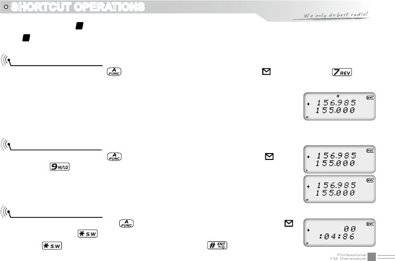
Frequency Reverse
Under standby state, press key, the top left corner of LCD displays “ ” icon, then press key to
set arrow directed channel as frequency reverse, repeat above operation to turn off frequency reverse.
1. When LCD displays “R” icon, it means current arrow directed channel open the
frequency reverse function, the TX frequency and RX frequency is interchanged,
if CTCSS/DCS signaling is set, it will also interchange.
2. When “R” icon disappears, it means reverse function is close.
TX Power selection
Under standby state, press key, the top left corner of LCD displays “ ” icon,
then press key to choose High/Low power for current arrow directed channel.
1. When LCD displays “L” icon, it means low power is chose.
2. When LCD displays “H” icon, it means high power is chose.
Stopwatch function
1. Under standby state, press key, the top left corner of LCD displays “ ”
icon, then press to enter into stopwatch function.
2. Press key to start timing. Under this state, press key to pause timing.
26
SHORTCUT OPERATIONS
When timing is pause, press key to continue timing.
3. Press [PF1], [PF2] or key to exit stop watch function.
NOTE: During timing, press key to stop timing and displays current data, press this key again to clear timer.
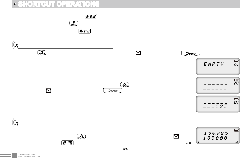
DTMF code Transmit and Enquiry
1. Press key, the top left corner of LCD displays “ ” icon, then press key, LCD displays
DTMF data and group number (total 16groups) of current group.
2. Rotate channel switch to choose desired group and DTMF data, press PTT key
to transmit selected DTMF signaling . If current group not edit DTMF data, LCD
displays “EMPTY”.
3. When current group displays “EMPTY”, press key, the top left corner of LCD
displays “ ” icon, press and hold key until transceiver emits “DU”
beep, transceiver enters into DTMF edit state, LCD displays “___________”, now
you can enter desired DTMF data by keypad.
4. When nished editing, press side key [PF2] to save DTMF signaling.
Keypad lock
In order to prevent wrong operation, user can make use of keypad lock function.
Under standby state, press key, the top left corner of LCD displays “ ” icon,
then press and hold key until transceiver emits “DU” beep, LCD displays “ ”
icon, keypad is locked. Repeat above operation, “ ” icon disappears, key lock function is cancelled.
27
Menu 1-14 of this transceiver are channel operations.Channel operations temporarily changed the functions
of current channel. When power off or channel has been changed, the relevant setup will be erased. Only
under VFO mode, the channel operations will be saved until next change. Menu 15-31 is background
operation, it is valid for all channels, the relevant setup will be saved until next change.
The operating methods are as follows:
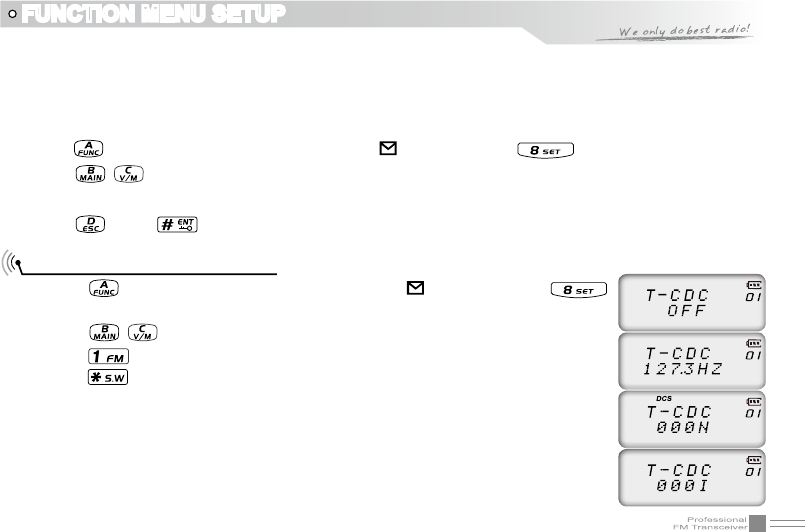
1. Press key, the top left corner of LCD displays “ ” icon, then press key to enter function menu.
2. Press / key to choose desired function.
3. Rotate channel switch to choose desired setting.
4. Press key or key to conrm and exit.
FUNCTION MENU SETUP
Note: User-defined CTCSS encode must be setup by programming software.
CTCSS/DCS Encode Setup
1. Press key, the top left corner of LCD displays “ ” icon, then press
key to enter into function menu.
2. Press / key to choose NO. 01 function item, it shows “T-CDC” on LCD.
3. Press key to choose CTCSS,DCS or OFF, when DCS signaling is selected,
press key to choose DCS positive or inverse code.
4. Rotate channel switch to choose desired CTCSS/DCS code.
CTCSS: 62.5HZ-254.1HZ, 51groups in total, and 1 group user-dened code.
DCS: 000N-777I, 232 groups in total. “N” stands for positive code, “I” stands for
inverse code.
28
FUNCTION MENU SETUP
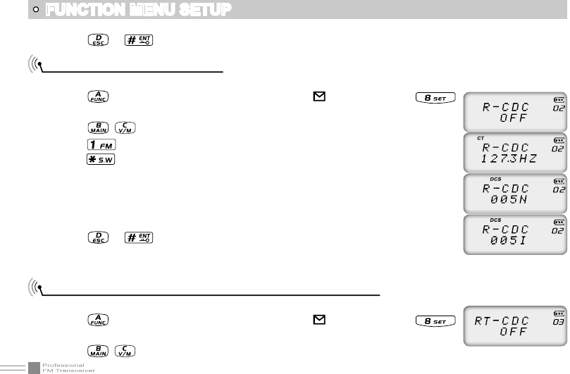
CTCSS/DCS Decode Setup
If this function is enabled, you can ignore (can not hear) other unrelated call at the same frequency.
1. Press key, the top left corner of LCD displays “ ” icon, then press
key to enter into function menu.
2. Press / key to choose NO. 02 function item, it shows “R-CDC” on LCD.
3. Press key to choose CTCSS,DCS or OFF, when DCS signaling is selected,
press key to choose DCS positive or inverse code.
4. Rotate channel switch to choose desired CTCSS/DCS code.
CTCSS:62.5HZ~254.1HZ,51 groups in total, and 1 group user-dened code.
DCS: 000N-777I, 232 groups in total. “N” stands for positive code, “I”
stands for inverse code.
5. Press or key to conrm and exit.
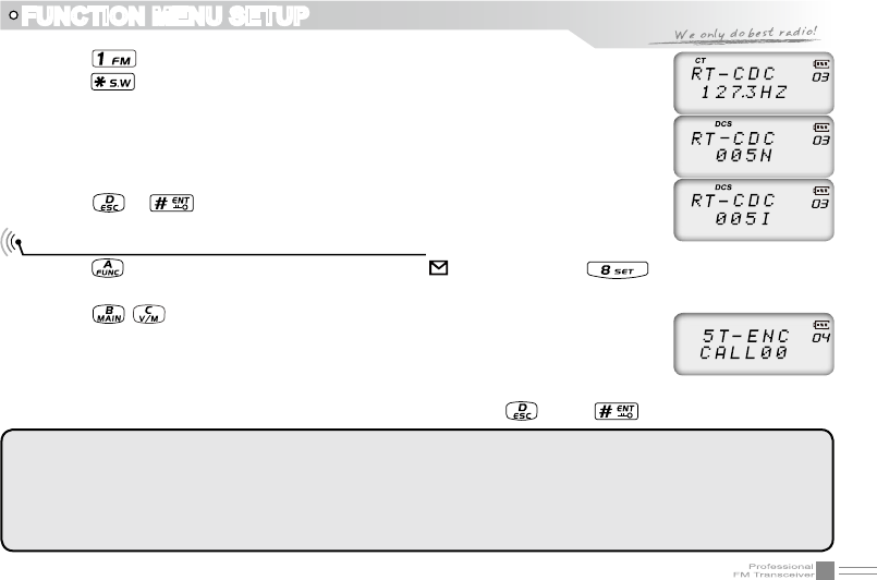
CTCSS/DCS Encode / Decode Synchronous Setup
This function is for adjusting CTCSS/DCS encode/decode synchronous.
1. Press key, the top left corner of LCD displays “ ” icon, then press
key to enter into function menu.
2. Press / key to choose NO. 03 function item, it shows “RT-CDC” on LCD.
5. Press or key to conrm and exit.
Note: User-defined CTCSS decode must be setup by programming software.
29
3. Press key to choose CTCSS,DCS or OFF, when DCS signaling is selected,
press key to choose DCS positive or inverse code.
4. Rotate channel switch to choose desired CTCSS/DCSencode/decode.
CTCSS: 62.5HZ~254.1HZ, 51groups in total, and 1 group user-dened code.
DCS: 000N-777I, 232 groups in total. “N” stands for positive code, “I”
stands for inverse code.
5. Press or key to conrm and exit.
FUNCTION MENU SETUP
5TONE encode must be programmed by software, only the groups with editing 5TONE can be
selected. When 5TONE encode is editing with name, transceiver will display name, otherwise
will display “ CALL XX ”.
Default configuration is 5TONE, 2TONE can be customized according to different market
requirements.
5TONE/2TONE encode group selection
1. Press key, the top left corner of LCD displays “ ” icon, then press key to enter into function
menu.
2. Press / key to choose NO. 04 function item, it shows “5T-ENC”/”2T-ENC”
on LCD.
3. Rotate channel switch to choose desired 5TONE encode group.
CALL00~CALL99, 100 groups in total for optional.
4. Press [PTT] key to transmit selected 5TONE encode, press key or key to conrm and exit.
30
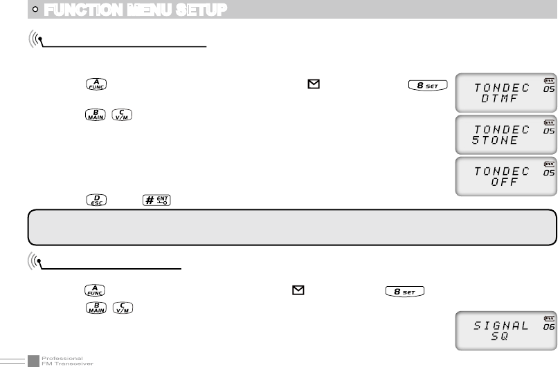
Squelch mode setup
This function is used for setting squelch mode to prevent receiving unrelated singals.
1. Press key, the top left corner of LCD displays “ ” icon, then press key enter into function menu.
2. Press / key to choose NO. 06 function item, it shows “SIGNAL” on LCD.
3. Rotate channel switch to choose desired squelch mode.
Optional signaling setup
DTMF and 5TONE functions are similar to CTCSS/DCS, it has special call functions, such as ANI, PTT ID, All call,
Alarm, remotely kill, remotely stun and remotely waken, etc..
1. Press key, the top left corner of LCD displays “ ” icon, then press
key to enter into function menu.
2. Press / key to choose NO. 05 function item, it shows “TONDEC” on LCD.
3. Rotate channel switch to choose desired optional signaling.
DTMF: current optional signaling is DTMF
5TONE/2TONE: current optional signaling is 5TONE/2TONE
OFF: close optional signaling
4. Press key or key to conrm and exit.
FUNCTION MENU SETUP
Default configuration is 5TONE , 2TONE can be customized according to different market
requirements.
31
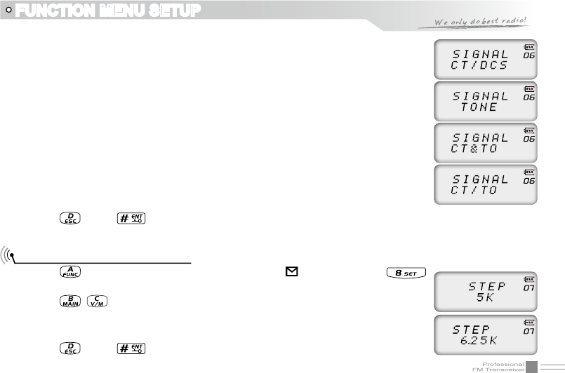
SQ: When current channel received matching RF signals, transceiver can hear
the talking from the other party.
CT/DCS: When current channel received matching RF signals and matching CTCSS/
DCS signaling, transceiver can hear the talking from the other party.
TONE: When current channel received matching RF signals and matching
optional signaling, transceiver can hear the talking from the other party.
CT&TO: When current channel received matching RF signals + matching optional
signaling + matching CTCSS/DCS signaling, transceiver can hear the
talking from the other party.
CT/TO: When current channel received matching RF signals, or matching optional
signaling, or matching CTCSS/DCS signaling, transceiver can hear the
talking from the other party.
4. Press key or key to conrm and exit.
Frequency step size setup
1. Press key, the top left corner of LCD displays “ ” icon, then press
key enter into function menu.
2. Press / key to choose NO. 07 function item, it shows “STEP” on LCD.
3. Rotate channel switch to choose desired step size.
4. Press key or key to conrm and exit.
FUNCTION MENU SETUP
Stepping: 2.5K,5K, 6.25K, 10K, 12.5K
32
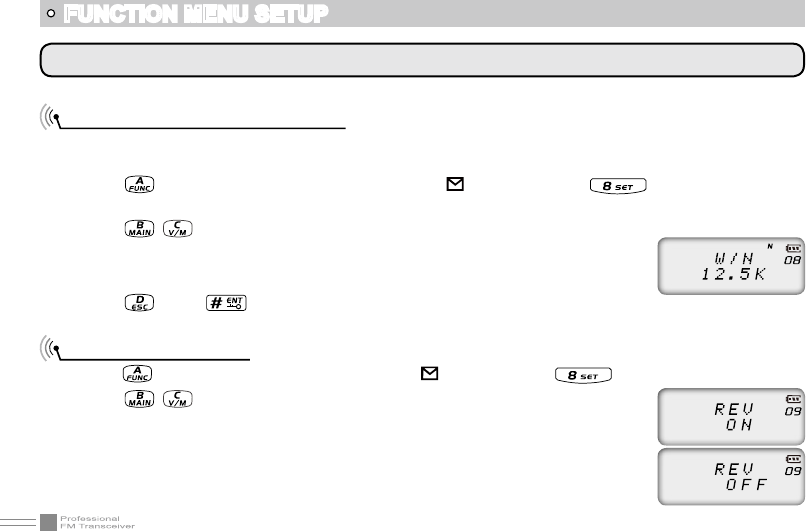
According to the national conditions of various countries, it can be set for communication by wide band or
narrow band.
1. Press key, the top left corner of LCD displays “ ” icon, then press
key enter into function menu.
2. Press / key to choose NO. 08 function item, it shows “W/N” on LCD.
3. Rotate channel switch to choose desired setup.
4. Press key or key to conrm and exit.
Frequency Reverse
1. Press key, the top left corner of LCD displays“ ” icon, then press key enter into function menu.
2. Press / key to choose NO. 09 function item, it shows “REV” on LCD.
3. Rotate channel switch to choose desired setup.
ON: Turn on Frequency reverse function, TX and RX frequency of current
channel will be interchanged. If CTCSS/DCS signaling is set, it also will
be interchanged.
FUNCTION MENU SETUP
NOTE: This function item will hide automatically when main band and sub main band are under channel mode.
Band Selection
12.5K: Narrow band
33
OFF: Close Frequency reverse function.
4. Press key or key to conrm and exit.
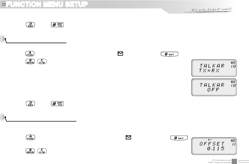
Talk Around ON/OFF
When this function is on, transceiver will cut communication with repeater.
1. Press key, the top left corner of LCD displays“ ” icon, then press key enter into function menu.
2. Press / key to choose NO. 10 function item, it shows “TALKAR” on LCD.
3. Rotate channel switch to choose desired setup.
TX-RX: Turn on Talk Around function, current channel will transmit at RX
frequency, if CTCSS/DCS signaling is set, it will interchange decoding
CTCSS/DCS as encoding.
OFF: Close Talk Around function.
4. Press key or key to conrm and exit.
Offset Frequency setup
This function works through repeater. When repeater receives signals at one frequency, it transmits at the
other frequency. The offset between these two frequencies is called offset frequency.
1. Press key, the top left corner of LCD displays “ ” icon, then press
key enter into function menu.
2. Press / key to choose NO. 11 function item, it shows “OFFSET” on LCD.
FUNCTION MENU SETUP
34
FUNCTION MENU SETUP
3. Rotate channel switch to choose desired offset frequency.
Frequency range is 00-70MHZ.
4. Press key or key to conrm and exit.
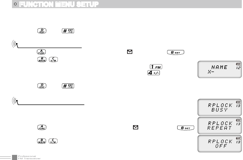
Editing Channel name
1. Press key, the top left corner of LCD displays“ ” icon, then press key enter into function menu.
2. Press / key to choose NO. 12 function item, it shows “-” on LCD.
3. Rotate channel switch to choose desired character, press key to conrm
current character and move shift to next character. Press key back to the
previous character.
4. Press key or key to conrm and exit.
Busy Channel Lockout
BCLO function is used for prohibit transmitting on busy channel, it can prevent
disturbing other transceivers operating in same frequency. If you press PTT, the
radio will beep as warning and get back to receiving state.
1. Press key, the top left corner of LCD displays “ ” icon, then press
key enter into function menu.
2. Press / key to choose NO. 13 function item, it shows “RPLOCK” on LCD.
3. Rotate channel switch to choose desired setup.
35
FUNCTION MENU SETUP
BUSY: Carrier wave lock, transmitting is prohibited when received matching carrier wave.
REPEAT: Signaling lock, transmitting is prohibited when received matching carrier but with unmatching
CTCSS/DCS.
OFF: Close BCLO function.
4. Press key or key to conrm and exit.
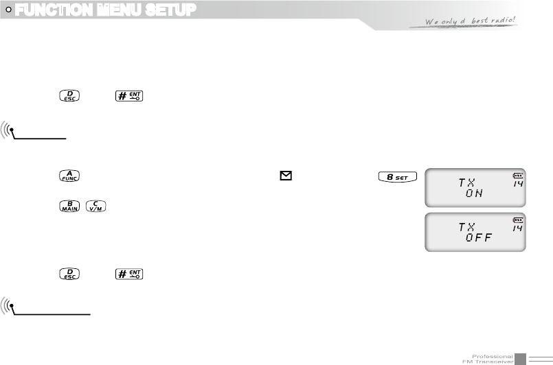
TX OFF
When this function is on, [PTT] key is unavailable. Current channel of transceiver only works under
receiving mode.
1. Press key, the top left corner of LCD displays “ ” icon, then press
key enter into function menu.
2. Press / key to choose NO. 14 function item, it shows “TX” on LCD.
3. Rotate channel switch to choose desired setup.
ON: TX OFF is enabled.
OFF: TX OFF is disabled.
4. Press key or key to conrm and exit.
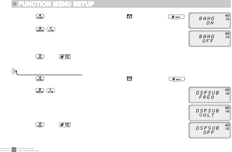
Band Limit
When this function is on, inputting frequency or Scanning frequency under VFO is limited in current VFO
frequency band.
36
1. Press key, the top left corner of LCD displays “ ” icon, then press
key enter into function menu.
2. Press / key to choose NO. 15 function item, it shows “BAND” on LCD.
3. Rotate channel switch to choose desired setup.
ON: Band limit is enabled.
OFF: Band limit is disabled.
4. Press key or key to conrm and exit.
Sub Band Display Setup
1. Press key, the top left corner of LCD displays “ ” icon, then press key enter into function
menu.
2. Press / key to choose NO. 16 function item, it shows “DSPSUB” on LCD.
3. Rotate channel switch to choose desired setup.
FREQ: Display sub band frequency or channel.
VOLT: Display current battery voltage.
OFF: Sub band display is disabled.
4. Press key or key to conrm and exit.
FUNCTION MENU SETUP
37
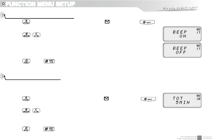
Keypad Voice Prompt Setup
1. Press key, the top left corner of LCD displays “ ” icon, then press key enter into function
menu.
2. Press / key to choose NO. 17 function item, it shows “BEEP” on LCD.
3. Rotate channel switch to choose desired setup.
ON: Keypad Voice Prompt is enabled.
OFF: Keypad Voice Prompt is disabled.
4. Press key or key to conrm and exit.
Time-Out-Timer (TOT)
The purpose of Time-out-Timer is to restrict transceiver for continuous long-term transmission. When the
continuous transmission time is beyond the preset time, transceiver is forced to stop transmitting and make
a beep sound.
1. Press key, the top left corner of LCD displays “ ” icon, then press
key enter into function menu.
2. Press / key to choose NO. 18 function item, it shows “TOT” on LCD.
3. Rotate channel switch to choose desired setup.
1~27 minutes, total 27minutes of TOT for optional, each interval is 1minute.
4. Press key or key to conrm and exit.
FUNCTION MENU SETUP
38
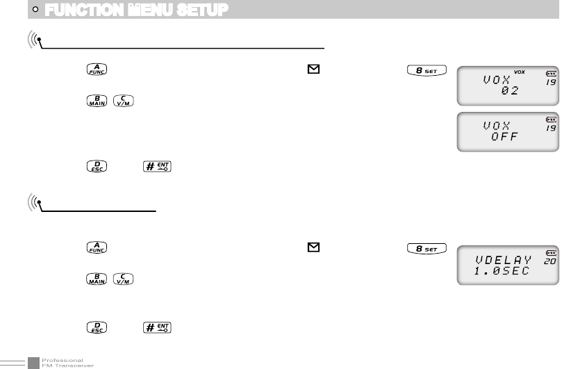
Voice Operated Transmission (VOX) Setup
When this function is on, the transmitting can be started by voice, no need to press [PTT] key.
1. Press key, the top left corner of LCD displays “ ” icon, then press
key enter into function menu.
2. Press / key to choose NO. 19 function item, it shows “VOX” on LCD.
3. Rotate channel switch to choose desired setup.
1~10 : Total 10 VOX levels for optional.
OFF: VOX function is disabled.
4. Press key or key to conrm and exit.
VOX Delay Setup
If transceiver returns to receive mode instantly after VOX calling, it may cause calling voice missing. To
avoid this problem, user can set a suitable delay time.
1. Press key, the top left corner of LCD displays “ ” icon, then press
key enter into function menu.
2. Press / key to choose NO. 20 function item, it shows “VDELAY” on LCD.
3. Rotate channel switch to choose desired setup.
0.5S-3S: Total 27 levels for optional, each interval is 0.1S
4. Press key or key to conrm and exit.
FUNCTION MENU SETUP
39
FUNCTION MENU SETUP
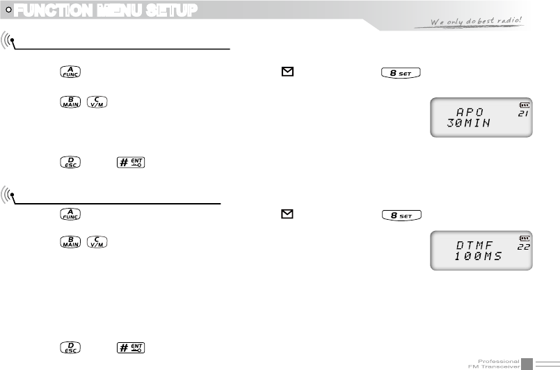
Automatic Power Off Time setup
When this function is on, transceiver will automatic power off when reach the preset time.
1. Press key, the top left corner of LCD displays “ ” icon, then press key enter into function
menu.
2. Press / key to choose NO. 21 function item, it shows “APO” on LCD.
3. Rotate channel switch to choose desired setup.
30minutes ~ 2hours: Total 3 levels for optional.
OFF: Automatic Power Off Time is disabled.
4. Press key or key to conrm and exit.
DTMF Transmitting Time Setup
1. Press key, the top left corner of LCD displays “ ” icon, then press key enter into function
menu.
2. Press / key to choose NO. 22 function item, it shows “DTMF” on LCD.
3. Rotate channel switch to choose desired setup.
50MS: Each DTMF signal transmits 50ms, interval 50ms
100MS: Each DTMF signal transmits 100ms, interval 100ms
200MS: Each DTMF signal transmits 200ms, interval 200ms
300MS: Each DTMF signal transmits 300ms, interval 300ms
500MS: Each DTMF signal transmits 500ms, interval 500ms
4. Press key or key to conrm and exit.
40
FUNCTION MENU SETUP
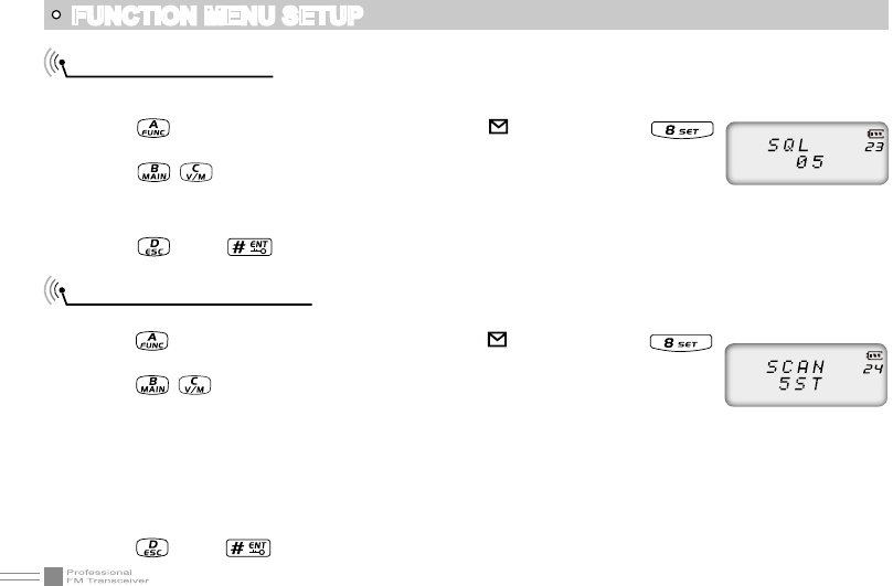
Squelch level setup
This function is used for setup intensity of receiving signals, transceiver will hear calls when receiving
signal intensity achieve preset data, otherwise, transceiver will keep mute.
1. Press key, the top left corner of LCD displays " " icon, then press
key enter into function menu.
2. Press / key to choose NO. 23 function item, it shows “SQL” on LCD.
3. Rotate channel switch to choose desired setup.
00~09 : 10 levels of squelch in total for optional, “00” is minimum setup value (normally open)
4. Press key or key to conrm and exit.
Scan Dwell Time Setup
There are three kinds of scan dwell time for optional.
1. Press key, the top left corner of LCD displays " " icon, then press
key enter into function menu.
2. Press / key to choose NO. 24 function item, it shows “SCAN” on LCD.
3. Rotate channel switch to choose desired setup.
5ST: When scanning matched signal, transceiver will stop scaning for 5seconds then resume.
10ST: When scanning matched signal, transceiver will stop scaning for 10seconds then resume.
15ST: When scanning matched signal, transceiver will stop scaning for 15seconds then resume.
2SP: When scanning matched signal, transceiver will stop scaning, 2seconds after signal disappeared,
then resume.
4. Press key or key to conrm and exit.
41
FUNCTION MENU SETUP
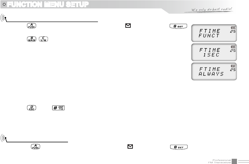
Function Icon Stay Time Setup
1. Press key, the top left corner of LCD displays “ ” icon, then press
key enter into function menu.
2. Press / key to choose NO. 25 function item, it shows “FTIME” on LCD.
3. Rotate channel switch to choose desired setup.
FUNCT: When nished function setting or enter into function menu, icon
disappeared.
1SEC: When nished function setting or enter into function menu, icon stay
1second then disappeared
2SEC: When nished function setting or enter into function menu, icon stay
2seconds then disappeared
3SEC: When nished function setting or enter into function menu, icon stay 3seconds then
disappeared
ALWAYS: Function icon is always display, only when pressing function key again, the icon will disappear.
4. Press key or key to conrm and exit.
NOTE: When function icon is staying, user can setup desired functions continuously, no need press function
key every time.
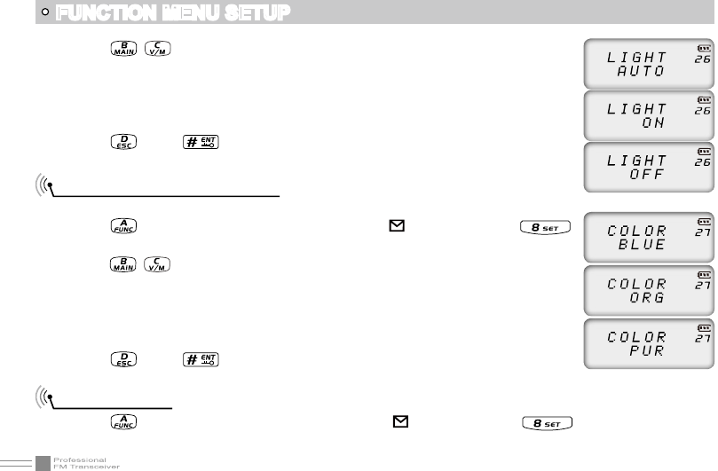
LCD Backlight Setup
1. Press key, the top left corner of LCD displays“ ” icon, then press key enter into function
menu.
42
FUNCTION MENU SETUP
2. Press / key to choose NO. 26 function item, it shows “LIGHT” on LCD.
3. Rotate channel switch to choose desired setup.
AUTO: Backlight will automatic closed after a period.
OFF: Always off.
ON: Always on.
4. Press key or key to conrm and exit.
LCD Backlight Color Setup
There are three kinds of backlight color for optional.
1. Press key, the top left corner of LCD displays“ ” icon, then press
key enter into function menu.
2. Press / key to choose NO. 27 function item, it shows “COLOR” on LCD.
3. Rotate channel switch to choose desired setup.
BLUE: Blue backlight
ORG: Orange backlight
PUR: Purple backlight
4. Press key or key to conrm and exit.
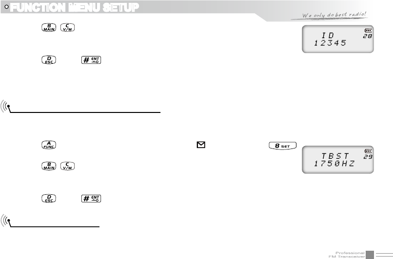
Self ID inquiry
1. Press key, the top left corner of LCD displays “ ” icon, then press key enter into function
menu.
43
FUNCTION MENU SETUP
2. Press / key to choose NO. 28 function item, it shows “ID” on LCD.
3. Rotate channel switch to choose desired setup.
The ID code displaying on LCD is transceiver self ID code.
4. Press key or key to conrm and exit.
NOTE: When current channel add 5TONE to be optional signaling, LCD displays 5TONE self ID code,
otherwise displays DTMF self ID code.
Tone Pulse Frequency Selection
This function is used for waking up sleeping repeater, it needs a certain intensity of Tone Pulse to wake up
sleeping repeater. In general, as long as the repeater has been waked up, no need to transmit Tone Pulse
again in preset time.
1. Press key, the top left corner of LCD displays “ ” icon, then press
key enter into function menu.
2. Press / key to choose NO. 29 function item, it shows “TBST” on LCD.
3. Rotate channel switch to choose desired setup.
1750HZ, 2100HZ, 1450HZ, 1000HZ, 4 kinds of Tone Pulse for optional
4. Press key or key to conrm and exit.
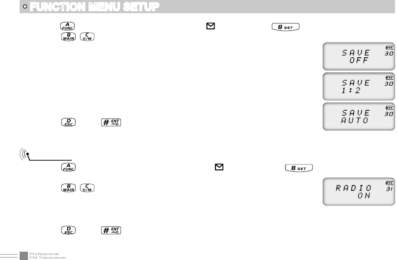
Battery Save Setup
User can setup battery save ratio according to requirements. The standby time can be extended when
enable battery save function, but if save ratio setting too high, it may cause voice missing.
44
FUNCTION MENU SETUP
1. Press key, the top left corner of LCD displays“ ” icon, then press key enter into function menu.
2. Press / key to choose NO. 30 function item, it shows “SAVE” on LCD.
3. Rotate channel switch to choose desired setup.
OFF: Battery Save is disabled.
1:2 The standby time between normal working state and battery saving mode is 1:2
1:3 The standby time between normal working state and battery saving mode is 1:3
1:5 The standby time between normal working state and battery saving mode is 1:5
1:8 The standby time between normal working state and battery saving mode is 1:8
AUTO: Battery save ratio is adjusting automatically.
4. Press key or key to conrm and exit.
FM radio
1. Press key, the top left corner of LCD displays“ ” icon, then press key enter into function
menu.
2. Press / key to choose NO. 31 function item, it shows “RADIO” on LCD.
3. Rotate channel switch to choose desired setup.
ON: FM radio function is enable.
OFF: FM radio function is disable.
4. Press key or key to conrm and exit.
NOTE: Only when this function is setting ON, FM radio can be normally used.
Remind: When single band UHF or VHF in standby, proposed setup is 1:8,
when dual band VV,UU or UV in standby, proposed setup is 1:2.
45
SENIOR FUNCTION OPERATIONS
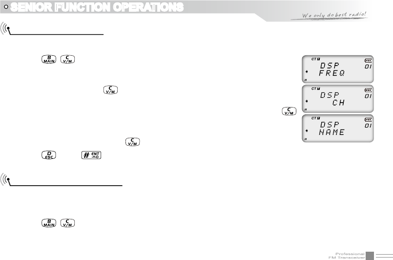
Display Mode Setup
There are three kinds of display modes for optional.
1. Press [PF2] key to turn on radio, hold [PF2] key until transceiver emits beep.
2. Press / key to choose No. 01 function item, it shows “DSP” on LCD.
3. Rotate channel switch to choose desired setup.
FREQ: Frequency + Channel mode, transceiver displays current channel name +
frequency, press key to switch into VFO mode.
CH: Channel mode, 1~21 items of function menu will hide automatically, user can
only operate some functions. It is unable to switch into VFO by pressing
key. This model can be used for Amateur mode.
NAME: Channel + Name Tag mode, transceiver displays current channel number
+ channel name, press key to switch into VFO mode.
4. Press key or key to conrm and exit.
Resume Factory Default
You can make all the settings of transceiver return to the factory default settings when transceiver can not
work normally because of wrong operation or error setup.
1. Press [PF2] key to turn on radio, hold [PF2] key until transceiver emits beep.
2. Press / key to choose No. 02 function item, it shows “RESTOR” on LCD.
3. Rotate channel switch to choose desired setup.
OFF: No operations.
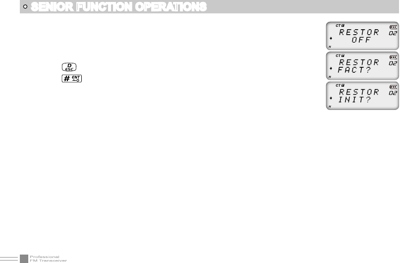
46
SENIOR FUNCTION OPERATIONS
FACT: Resume all items to factory default, including channel and background
settings.
INIT: Resume background settings to factory default, channel operations are
keeping.
4. Press key to exit current selection
5. Press key to conrm current selection.
47
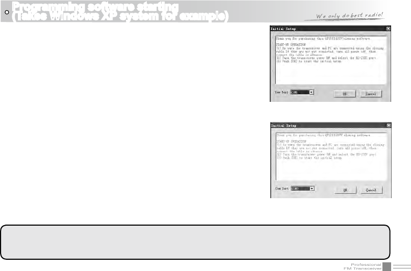
Programming software starting
(Takes Windows XP system for example)
(picture 1)
(picture 2)
1.Double Click “QPS3318UV setup.exe”, then go on installing as
computer command.
2.Click “START” menu of computer, choose “USB To COM” in QPS3318UV
item and click it. Please install USB To Comport drive program as
computer command.
3.Please plug PC03 programming cable into USB port of PC device, then
connect to transceiver.
4.Double click “QPS3318UV” shortcut icon, or click QPS3318UV item in
“START” menu to open programming software interface.
5.Choose “COM Port” as computer command, then click “OK” to start
programming software.
NOTE: In same computer, if programming cable plugs into different USB
port, the COM Port number is different.
Before programming, transceiver should be turned on rstly.
Not turn on or turn off transceiver when it is connecting with computer,
otherwise it may cause transceiver not read or write data. If this
situation is happened, please shut down programming software, remove
programming cable from computer, then re-plug cable into computer and
re-start programming software, re-choose COM Port, the programming
will work normally.
NOTE:
The programming software is attached with product identifying system. In first time run, the transceiver
should be connected to computer, otherwise the software can not run.
48
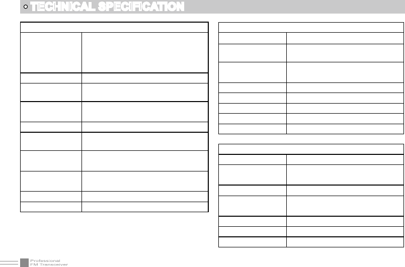
General
Frequency Range
VHF:136~174MHz
UHF:400~480MHZ
Channel Capacity 200 channels
Channel Spacing 12.5KHz (narrow band)
Phase-locked
Step 0.1KHz
Operation Voltage 7.4V DC ±20%
Battery Life More than 12 Hours(1500mAh),by 5-5-
90 working cycle
Frequency
Stability ±2.5ppm
Operation
Temperature -20℃~ +55℃
Size 240×56×30mm (with battery,antenna)
Weight 210g (with battery,antenna)
TECHNICAL SPECIFICATION
Receiving Part
Narrow band
Sensitivity
(12dB SINAD) ≤0.35μV
Adjacent Channel
Selecitvity ≥60dB
Intermodulation ≥60dB
Spurious Rejection ≥70dB
Hum & Noise ≥40dB
Audio Distortion ≤5%
Audio Power Output 1000mW/10%
Transimitting Part
Narrow band
Power Output (VHF)
(UHF)
Modulation 11KΦF3E
Adjacent Channel
Power ≥60dB
Hum & Noise ≥40dB
Spurious Emission ≤-36dB
Audio Distortion ≤5%
5W
4W
49
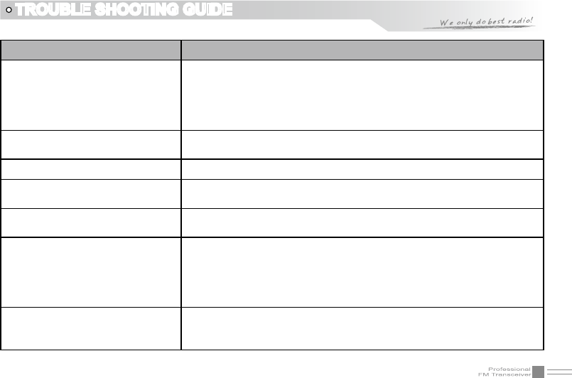
TROUBLE SHOOTING GUIDE
Problem Corrective Action
No power
A.The battery may be exhausting. Recharge or replace the battery.
B.The battery may not be installed correctly. Remove the battery
and install it again.
C.The power switch is broken; send it to local dealers to repair.
D.Battery touch is broken; send it to local dealers to repair.
Battery power dies shortly after
charging. The battery life is finished. Replace the battery pack with a new one.
Transceiver cannot scan The channels are not in scan list. (Professionals set it.)
All band noisy after programmed Turn on squelch when programmed. Non-professionals are advised
not rammed to adjust this function.
No sound after using earphone.
for a while Earphone jack is broken. Please contact with local dealers to repair.
Communication distance
becomes short, and Low
sensitivity
A.Check whether the antenna is in good conduction and the antenna
base do not come adrift.
B.Antenna connector is broken or not or with sundries.Whether it
has set in low power output. (Please contact with local dealers to
repair.)
Cannot talk or hear other
members in your group
A.Different frequency or channel, please change it.
B.Different CTCSS / DCS /DTMF, please reset it.
C.Out of communication range.
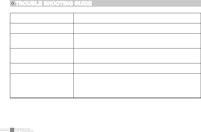
50
Can not power on or frequent
power off Check weather the battery touch is out of sharp or broken.
The receiving sound gets low or
intermittent
Check weather the MIC is stoppage. Otherwise, please contact with
local dealers to repair it.
Receiving intermittent with in big
noise
A.Out of communication range or obstruct by tall buildings or in big
noise.
B.450 filter is broken, Please contact with local dealers to repair.
Loudspeaker become lower or
with“ka ka”sound after using a
certain time
Check whether the loudspeaker is broken, Iron powder or sundries is
in the loudspeaker. Please contact with local dealers to repair.
Receive voice from the other
party but can not transmit Check [PTT] key.
Receiving indicator with green
light but no sound
A.Low volume, please clockwise to turn on.
B.Loudspeaker is broken, please contact with local dealers to repair.
C.Earphone jack is broken, please contact with local dealers to
repair.
D.Volume switch is broken.
TROUBLE SHOOTING GUIDE
51
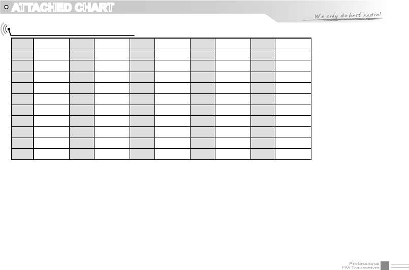
ATTACHED CHART
CTCSS Frequency Chart
1 62.5 12 94.8 23 136.5 34 177.3 45 218.1
2 67.0 13 97.4 24 141.3 35 179.9 46 225.7
3 69.3 14 100.0 25 146.2 36 183.5 47 229.1
4 71.9 15 103.5 26 151.4 37 186.2 48 233.6
5 74.4 16 107.2 27 156.7 38 189.9 49 241.8
6 77.0 17 110.9 28 159.8 39 192.8 50 250.3
7 79.7 18 114.8 29 162.2 40 196.6 51 254.1
8 82.5 19 118.8 30 165.5 41 199.5 52
9 85.4 20 123.0 31 167.9 42 203.5
10 88.5 21 127.3 32 171.3 43 206.5
11 91.5 22 131.8 33 173.8 44 210.7
user-dened
52
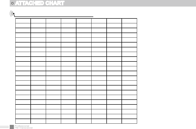
ATTACHED CHART
1024 groups DCS frequency chart
000 001 002 003 004 005 006 007
010 011 012 013 014 015 016 017
020 021 022 023 024 025 026 027
030 031 032 033 034 035 036 037
040 041 042 043 044 045 046 047
050 051 052 053 054 055 056 057
060 061 062 063 064 065 066 067
070 071 072 073 074 075 076 077
100 101 102 103 104 105 106 107
110 111 112 113 114 115 116 117
120 121 122 123 124 125 126 127
130 131 132 133 134 135 136 137
140 141 142 143 144 145 146 147
150 151 152 153 154 155 156 157
160 161 162 163 164 165 166 167
170 171 172 173 174 175 176 177
200 201 202 203 204 205 206 207
210 211 212 213 214 215 216 217
220 221 222 223 224 225 226 227
230 231 232 233 234 235 236 237
240 241 242 243 244 245 246 247
250 251 252 253 254 255 256 257
53
ATTACHED CHART
260 261 262 263 264 265 266 267
270 271 272 273 274 275 276 277
300 301 302 303 304 305 306 307
310 311 312 313 314 315 316 317
320 321 322 323 324 325 326 327
330 331 332 333 334 335 336 337
340 341 342 343 344 345 346 347
350 351 352 353 354 355 356 357
360 361 362 363 364 365 366 367
370 371 372 373 374 375 376 377
400 401 402 403 404 405 406 407
410 411 412 413 414 415 416 417
420 421 422 423 424 425 426 427
430 431 432 433 434 435 436 437
440 441 442 443 444 445 446 447
450 451 452 453 454 455 456 457
460 461 462 463 464 465 466 467
470 471 472 473 474 475 476 477
500 501 502 503 504 505 506 507
510 511 512 513 514 515 516 517
520 521 522 523 524 525 526 527
530 531 532 533 534 535 536 537
54
540 541 542 543 544 545 546 547
550 551 552 553 554 555 556 557
560 561 562 563 564 565 566 567
570 571 572 573 574 575 576 577
600 601 602 603 604 605 606 607
610 611 612 613 614 615 616 617
620 621 622 623 624 625 626 627
630 631 632 633 634 635 636 637
640 641 642 643 644 645 646 347
650 651 652 653 654 655 656 657
660 661 662 663 664 665 666 667
670 671 672 673 674 675 676 677
700 701 702 703 704 705 706 707
710 711 712 713 714 715 716 717
720 721 722 723 724 725 726 727
730 731 732 733 734 735 736 737
740 741 742 743 744 745 746 747
750 751 752 753 754 755 756 757
760 761 762 763 764 765 766 767
770 771 772 773 774 775 776 777
ATTACHED CHART
NOTE: N stands for positive code. I stands for inverted code. 1024 groups of DCS in total.

SAFETYTRAININGINFORMATION
YourQixiangElectronScience&TechnologyCo.,LtdradiogeneratesRFelectromagnetic
energyduringtransmitmode.Thisradioisdesignedforandclassifiedas“OccupationalUse
Only”,meaningitmustbeusedonlyduringthecourseofemploymentbyindividualsaware
ofthehazards,andthewaystominimizesuchhazards.ThisradioisNOTintendedforuseby
the“GeneralPopulation”inanuncontrolledenvironment.
ThisradiohasbeentestedandcomplieswiththeFCCRFexposurelimitsfor“OccupationalUseOnly”.Inaddition,
yourQixiangElectronScience&TechnologyCo.,LtdradiocomplieswiththefollowingStandardsandGuidelines
withregardtoRFenergyandelectromagneticenergylevelsandevaluationofsuchlevelsforexposuretohumans:
FCC OET Bulletin 65 Edition 97-01 Supplement C, Evaluating Compliance with FCC Guidelines for Human Exposure to
Radio Frequency Electromagnetic Fields.
American National Standards Institute (C95.1-1992), IEEE Standard for Safety Levels with Respect to Human Exposure
to Radio Frequency Electromagnetic Fields, 3 kHz to 300 GHz.
American National Standards Institute (C95.3-1992), IEEE Recommended Practice for the Measurement of Potentially
Hazardous Electromagnetic Fields– RF and Microwave.
Theinformationlistedaboveprovidestheuserwiththeinformationneededtomakehimor
herawareofRFexposure,andwhattodotoas‐surethatthisradiooperateswiththeFCCRF
exposurelimitsofthisradio.
ElectromagneticInterference/Compatibility
Duringtransmissions,yourQixiangElectronScience&TechnologyCo.,LtdradiogeneratesRFenergythatcan
possiblycauseinterferencewithotherdevicesorsystems.Toavoidsuchinterference,turnofftheradioinareas
wheresignsarepostedtodoso.DONOToperatethetransmitterinareasthataresensitivetoelectromagnetic
radiationsuchashospitals,aircraft,andblastingsites.
Occupational/ControlledUse
Theradiotransmitterisusedinsituationsinwhichpersonsareexposedasconsequenceoftheiremployment
providedthosepersonsarefullyawareofthepotentialforexposureandcanexercisecontrolovertheirexposure.
Attention:
This radio complieswith IEEE and ICNIRP exposure limits for occupational/controlled RF exposure emvironment at operating duty
factors of up to 50% and is authorized by the FCC for occupational use only. An appropriate warning lable is affixed to all units.
In order to comply with RF exposure requirements, a minimum distance of 2.5cm must be maintained when held-to-face, and
body-worn operations are restricted to the approved original acessories (belt clip).
Do not use this device when antenna shows obvious damages!