Qixiang Electron Science and Technology UV8D TWO WAY RADIO User Manual 15 UV8 UserMan
Qixiang Electron Science& Technology Co., Ltd TWO WAY RADIO 15 UV8 UserMan
UserManual.wiki
>
Qixiang Electron Science and Technology
>
UV8D User Manual
15_UV8 UserMan.pdf
Navigation menu
Upload a User Manual
Namespaces
Wiki Guide
HTML
PDF
Info
Views
User Manual
Discussion / Help
Navigation

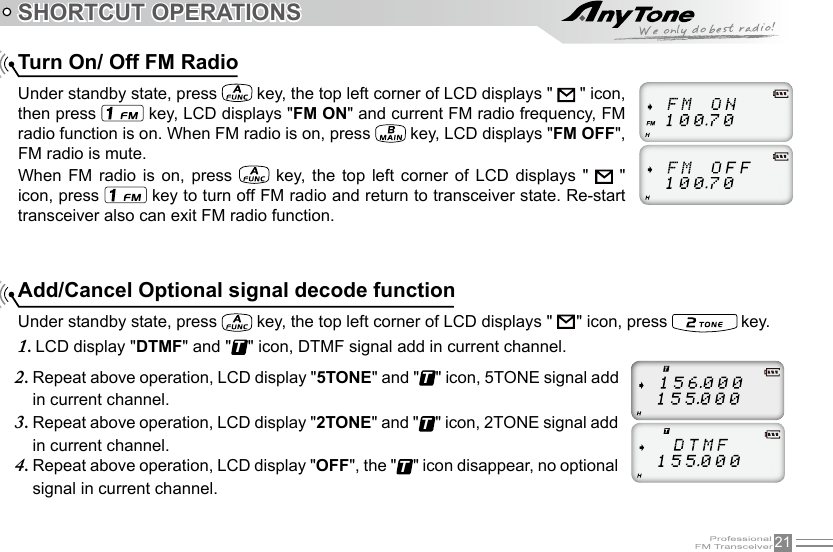
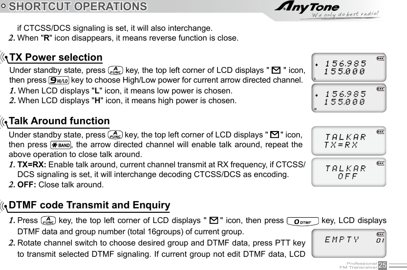
![IITABLE OF CONTENTSChannel Adjusting ................................................................................................................................................................................. 15Frequency Adjusting ............................................................................................................................................................................. 15Frequency Input by Keypad ............................................................................................................................................................. 16Channel Input by Keypad .................................................................................................................................................................. 16Squelch Off Momentary / Squelch Off .........................................................................................................................................16Receiving ................................................................................................................................................................................................... 17Transmitting ..............................................................................................................................................................................................17Emergency Alarm .................................................................................................................................................................................. 18Side Key [PF1] function instruction ............................................................................................................................................... 18Side key [PF2] function instruction................................................................................................................................................ 19Edit channel .............................................................................................................................................................................................. 19Delete channel ........................................................................................................................................................................................ 19SHORTCUT OPERATIONS ..................................................................................................................................................................... 21Turn On/ Off FM Radio........................................................................................................................................................................ 21Add/Cancel Optional signal decode function ........................................................................................................................... 21CTCSS/DCS Scan ................................................................................................................................................................................ 22Offset Frequency Direction Setup ................................................................................................................................................. 23Frequency/Channel Scan .................................................................................................................................................................. 23Channel Scan Skip ............................................................................................................................................................................... 24Frequency Reverse .............................................................................................................................................................................. 24TX Power selection ............................................................................................................................................................................... 25Talk Around function ............................................................................................................................................................................. 25DTMF code Transmit and Enquiry ................................................................................................................................................ 25Keypad lock .............................................................................................................................................................................................. 26Single-band Switching ......................................................................................................................................................................... 27CTCSS/DCS Encode and Decode................................................................................................................................................ 27](https://usermanual.wiki/Qixiang-Electron-Science-and-Technology/UV8D/User-Guide-2983245-Page-6.png)
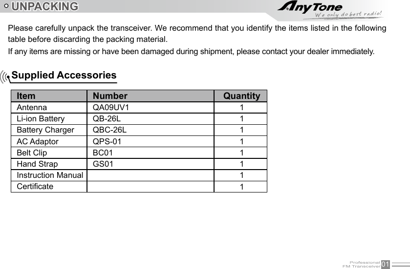
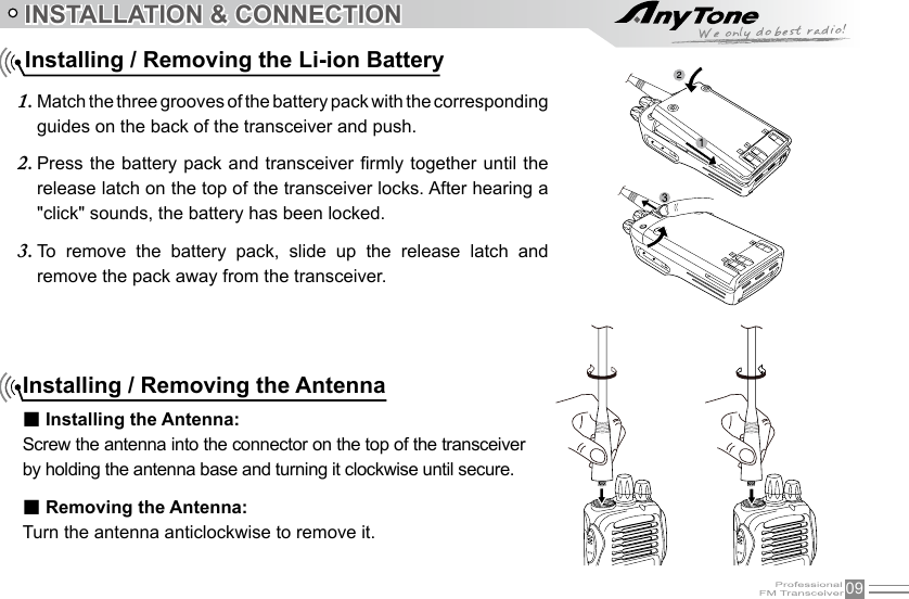
![14 Turn the Radio On & OFFNOTE:Press the side key of Squelch Off to monitor the background noise. Turn [POWER] / [VOLUME] to adjust the volume. Turn [Selector Knob] to adjust squelch level for current channel.BASIC OPERATIONSUnder power-off state, turn [POWER]/ [VOLUME] clockwise to turn on the transceiver.Under power-on state, turn [POWER]/ [VOLUME] anticlockwise to turn off the transceiver.Under power-on state, turn [POWER] / [VOLUME] to adjust volume. Clockwise-up, anticlockwise -down.When adjusting the volume, user can press the key of Squelch Off to monitor volume level.Adjusting Volume](https://usermanual.wiki/Qixiang-Electron-Science-and-Technology/UV8D/User-Guide-2983245-Page-21.png)
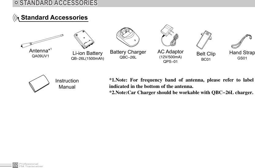
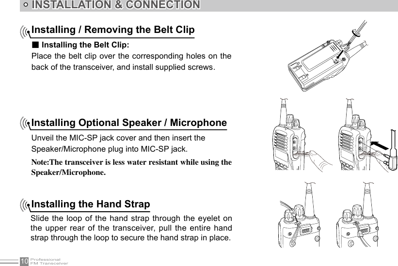
![16BASIC OPERATIONSFrequency Input by KeypadUnder frequency mode or FM radio frequency mode, you can directly enter frequency through keypad.When your transceiver is under Channel mode, press 1. key to switch into VFO.NOTE: When the transceiver is under Channel mode, it shows current channel number on the right of main frequency.Enter the desired frequency by keypad.2. NOTE: The frequency input of main channel or FM radio is relevant to the stepping and transceiver frequency range. If frequency setup is beyond range or not matching with step size, the input is unavailable. Under the FM radio mode, the frequency step size input by numeric keys is 100k.NOTE: Channel step:2.5K, 5K, 6.25K, 10K, 12.5K, 20K, 25K in total 7 for optional. Channel Input by KeypadUnder channel mode of transceiver or FM radio, you can switch to desired channel by entering three numbers (000-199). If the entered channel is not a saved channel, the transceiver will emit beep to prompt wrong input and return to current channel. For example, entering 001 is channel 1, 030 is channel 30, 125 is channel 125.Squelch Off Momentary / Squelch OffSide key [PF2] can be setup for Squelch off Momentary or Squelch off function.](https://usermanual.wiki/Qixiang-Electron-Science-and-Technology/UV8D/User-Guide-2983245-Page-23.png)
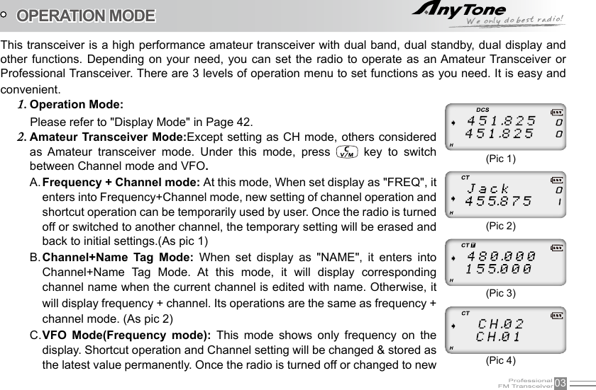
![17BASIC OPERATIONSTransmittingAccording to [PF2] key setup, hold [PF2] key to monitor the channel to ensure it is not busy, press PTT key and talk to speaker.Please keep the distance between mouth and speaker to be 2.5-5CM, speak in normal tone to get the best acoustic delity.ReceivingWhen your transceiver is called by other party, green or blue LED light will be on, LCD backlight will be on at the same time, and the arrow icon will ash, you can hear the calling.NOTE: You may not receive the calling when your transceiver is set at high squelch level. If current channel is set with decode signal, only the same signaling call can be heard.Squelch off: Press [PF2] key, squelch circuit is not mute, back-ground noise can be heard. Press [PF2] 1. key again, squelch circuit is mute.Squelch off Momentary: Press and hold [PF2] key, squelch circuit is not mute, back-ground noise can be 2. heard. Release [PF2] key, squelch circuit is mute.NOTE: When press and hold PTT key, transceiver is transmitting if the red LED light is on, release PTT key to receive calls.NOTE: The above functions are only available after [PF2] key setup. When in channel mode, opening squelch will show the frequency of the channel.](https://usermanual.wiki/Qixiang-Electron-Science-and-Technology/UV8D/User-Guide-2983245-Page-24.png)
![18BASIC OPERATIONSEmergency AlarmUnder standby state, press and hold [PF1] key (when it is ALARM function) until LCD displays "ALARM", Emergency alarm function is started. This transceiver has 4 Alarm modes. Power off transceiver to exit Alarm.Side Key [PF1] function instruction[PF1] key can be setup in Function Menu 45 for below functions:VOLT:1. Battery capacity inquiry: Under standby, press [PF1] key, LCD displays current battery capacity, press this key again to exit.CALL:2. Transmit the prestored DTMF/5TONE Encode signal in channel.ALARM:3. Long pressing [PF1] key, LCD display "ALARM", transceiver will enable the preset alarm function.SUBPTT: 4. Press [PF1] key, transceiver will transmit on sub-band frequency.Transmit tone pulse frequency: 5. Press and hold PTT key, then press [PF1] key to transmit selected tone pulse frequency.NOTE: The tone pulse frequency can be set to 1750Hz, 1450Hz, 1000Hz or 2100Hz.Please refer to function menu No.32 Tone plus frequency setup (Page 33).](https://usermanual.wiki/Qixiang-Electron-Science-and-Technology/UV8D/User-Guide-2983245-Page-25.png)
![19 BASIC OPERATIONSSide key [PF2] function instructionSquelch off: Press [PF2] key, squelch circuit is not mute, back-ground noise can be heard. Press [PF2] 1. key again, squelch circuit is mute.Squelch off Momentary: Press and hold [PF2] key, squelch circuit is not mute, back-ground noise can 2. be heard. Release [PF2] key, squelch circuit is mute.Transmit DTMF/5TONE/2TONE signaling: Press and hold [PTT] key, then press [PF2] key to transmit 3. selected DTMF/5TONE/2TONE signaling.Press and hold [PF2] key to turn on transceiver, until transceiver emits "DU" beep, transceiver enter into 4. general functions setup.Delete channelUnder standby state, press 1. key, the top left corner of LCD displays " " icon, press key to switch into channel mode, channel number ashes. Edit channelUnder frequency mode (VFO), enter desired frequency and settings, press 1. key, the top left corner of LCD displays " " icon, press key to switch into channel mode, channel number ashes.Rotate channel switch to select desired editing channel number.2. Press 3. key, the top left corner of LCD displays " " icon, press and hold key until transceiver emits "DUDU" beep, channel is stored successfully.](https://usermanual.wiki/Qixiang-Electron-Science-and-Technology/UV8D/User-Guide-2983245-Page-26.png)
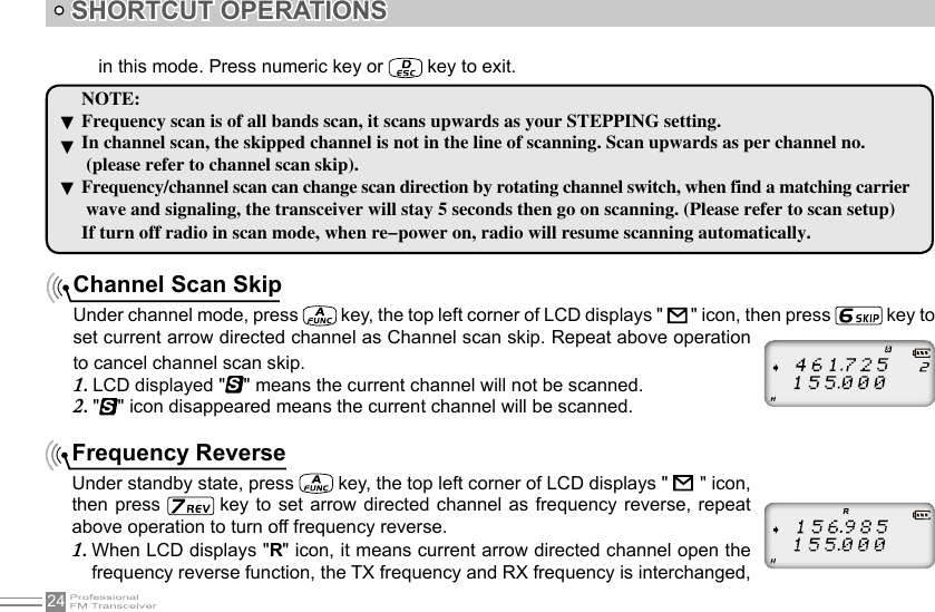
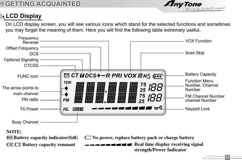
![26SHORTCUT OPERATIONSKeypad lockIn order to prevent wrong operation, user can make use of keypad lock function.When keypad lock is turned on, only channel selector is available for changing channels, all other keys are locked. Keypad lock operation can be done through radio itself. Under standby state, press key, the top left corner of LCD displays " " icon, then press and hold key until transceiver emits "DU" beep, LCD displays " " icon, keypad is locked. Repeat above operation, " " icon disappears, key lock function is cancelled. displays "EMPTY".When current group displays "3. EMPTY", press key, the top left corner of LCD displays " " icon, press and hold key until transceiver emits "DU" beep, transceiver enters into DTMF edit state, LCD displays "___________", now you can enter desired DTMF data by keypad.When nished editing, press side key [PF2] to save DTMF signaling.4.](https://usermanual.wiki/Qixiang-Electron-Science-and-Technology/UV8D/User-Guide-2983245-Page-33.png)
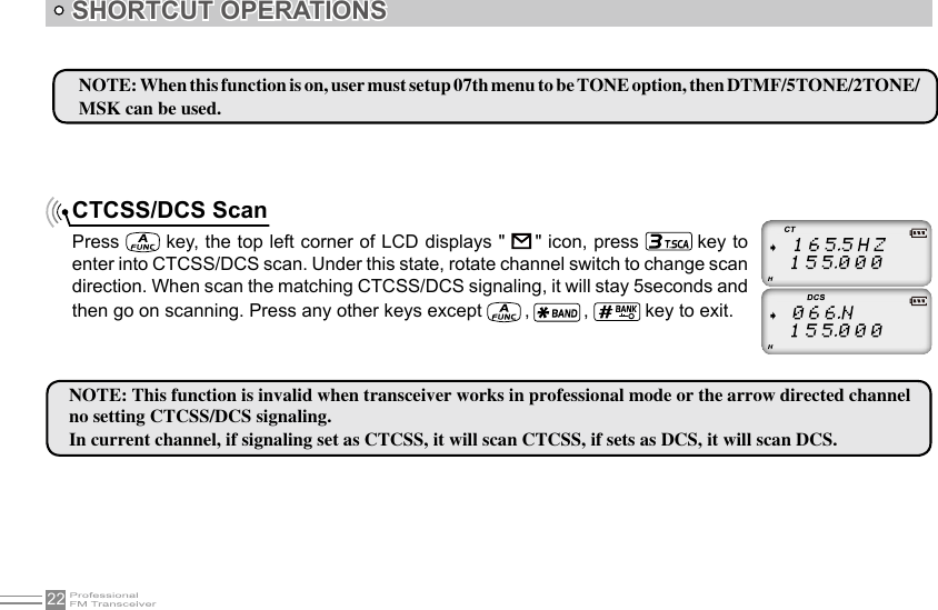
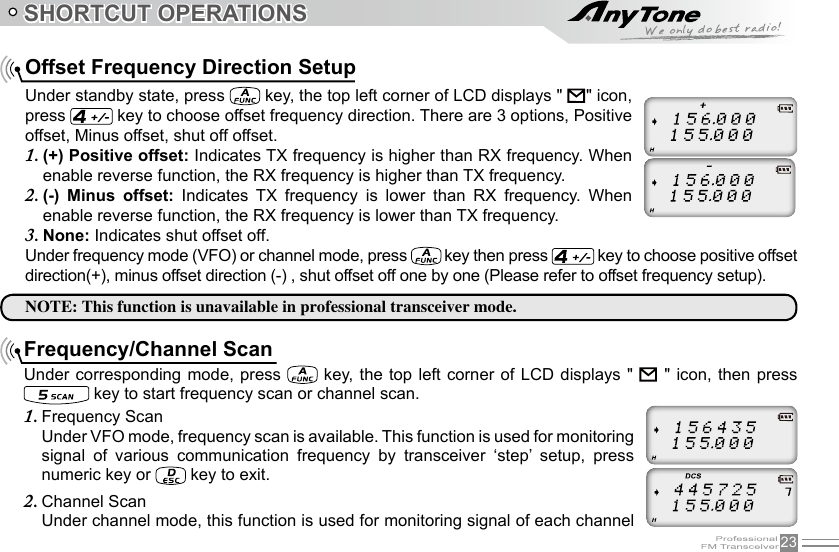
![27SHORTCUT OPERATIONS Single-band Switching CTCSS/DCS encode and decode To reduce interference from the sub-band when only the main-band is needed. You can use the single-band switching function to turn off the sub-band quickly. Continuous pressing of will cycle LCD display to show Main + Sub-Band / Sub-Band Only / Main-Band Only.Press 1. key then press [PF2] to enter into setup.Press [PF2] key to choose CTCSS, DCS or OFF, when choose DCS, press 2. key to select positive or negative code.Rotate Channel selector to choose desired CTCSS/DCS encode and decode.3. Press 4. key or key to conrm and exit.](https://usermanual.wiki/Qixiang-Electron-Science-and-Technology/UV8D/User-Guide-2983245-Page-34.png)
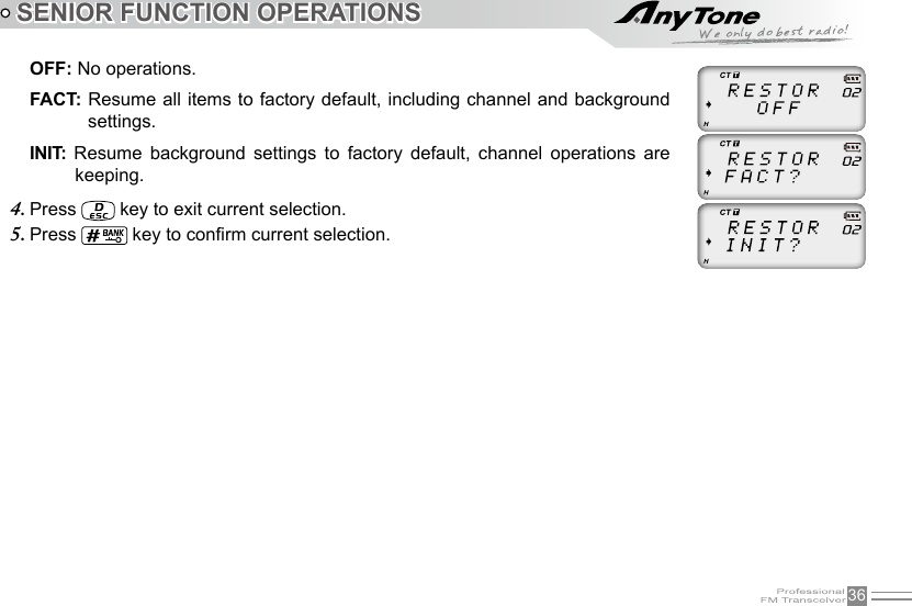
![35SENIOR FUNCTION OPERATIONSDisplay Mode SetupThere are three kinds of display modes for optional.Press [PF2] key to turn on radio, hold [PF2] key until transceiver emits beep.1. Press 2. / key to choose No.01 function item, it shows "DSP" on LCD.Rotate channel switch to choose desired setup.3. FREQ: Frequency+Channel mode, transceiver displays current channel name + frequency, press key to switch into VFO mode.CH: Channel mode, 1~24 items of function menu will hide automatically, user can only operate some functions. It is unable to switch into VFO by pressing key. This model can be used for Amateur mode.NAME: Channel+Name Tag mode, transceiver displays current channel number +channel name, press key to switch into VFO mode.Press 4. key or key to conrm and exit.Resume Factory DefaultYou can make all the settings of transceiver return to the factory default settings when transceiver can not work normally because of wrong operation or error setup.Press [PF2] key to turn on radio, hold [PF2] key until transceiver emits beep.1. Press 2. / key to choose No.02 function item, it shows "RESTOR" on LCD.Rotate channel switch to choose desired setup.3.](https://usermanual.wiki/Qixiang-Electron-Science-and-Technology/UV8D/User-Guide-2983245-Page-42.png)
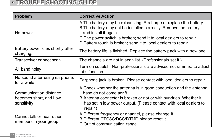
![42Can not power on or frequent power off Check weather the battery touch is out of sharp or broken.The receiving sound gets low or intermittentCheck weather the MIC is stoppage. Otherwise, please contact with local dealers to repair it.Receiving intermittent with in big noiseA.Out of communication range or obstruct by tall buildings or in big noise.B.450 lter is broken, Please contact with local dealers to repair.Loudspeaker become lower or with"ka ka"sound after using a certain timeCheck whether the loudspeaker is broken, Iron powder or sundries is in the loudspeaker. Please contact with local dealers to repair.Receive voice from the other party but can not transmit Check [PTT] key.Receiving indicator with green light but no soundA.Low volume, please clockwise to turn on.B.Loudspeaker is broken, please contact with local dealers to repair.C.Earphone jack is broken, please contact with local dealers to repair.D.Volume switch is broken.TROUBLE SHOOTING GUIDE](https://usermanual.wiki/Qixiang-Electron-Science-and-Technology/UV8D/User-Guide-2983245-Page-49.png)