Qual Tron QTIEMIDSMMCT MMCT – MIDS Multi Frequency Transmitter User Manual MMCT MMCR Manual 24 Aug 2006
Qual-Tron, Inc. MMCT – MIDS Multi Frequency Transmitter MMCT MMCR Manual 24 Aug 2006
UserManual.wiki
>
Qual Tron
>
QTIEMIDSMMCT User Manual
User Manual
Navigation menu
Upload a User Manual
Namespaces
Wiki Guide
HTML
PDF
Info
Views
User Manual
Discussion / Help
Navigation
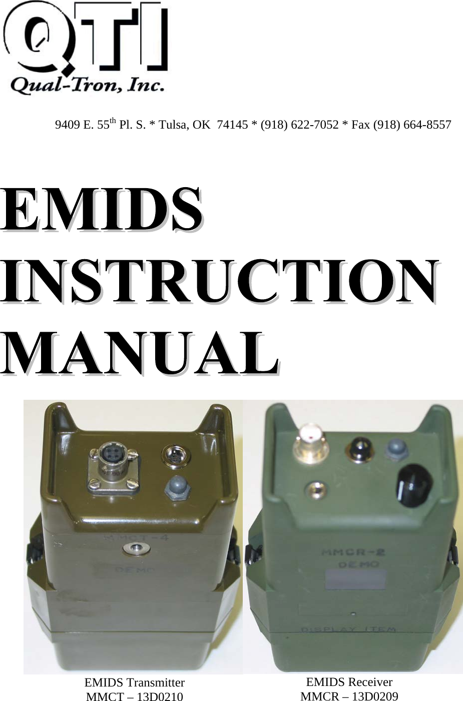
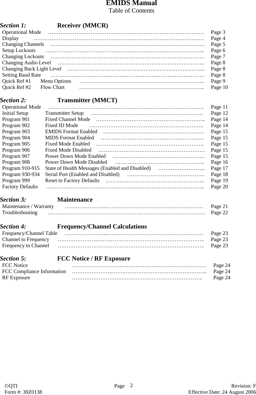
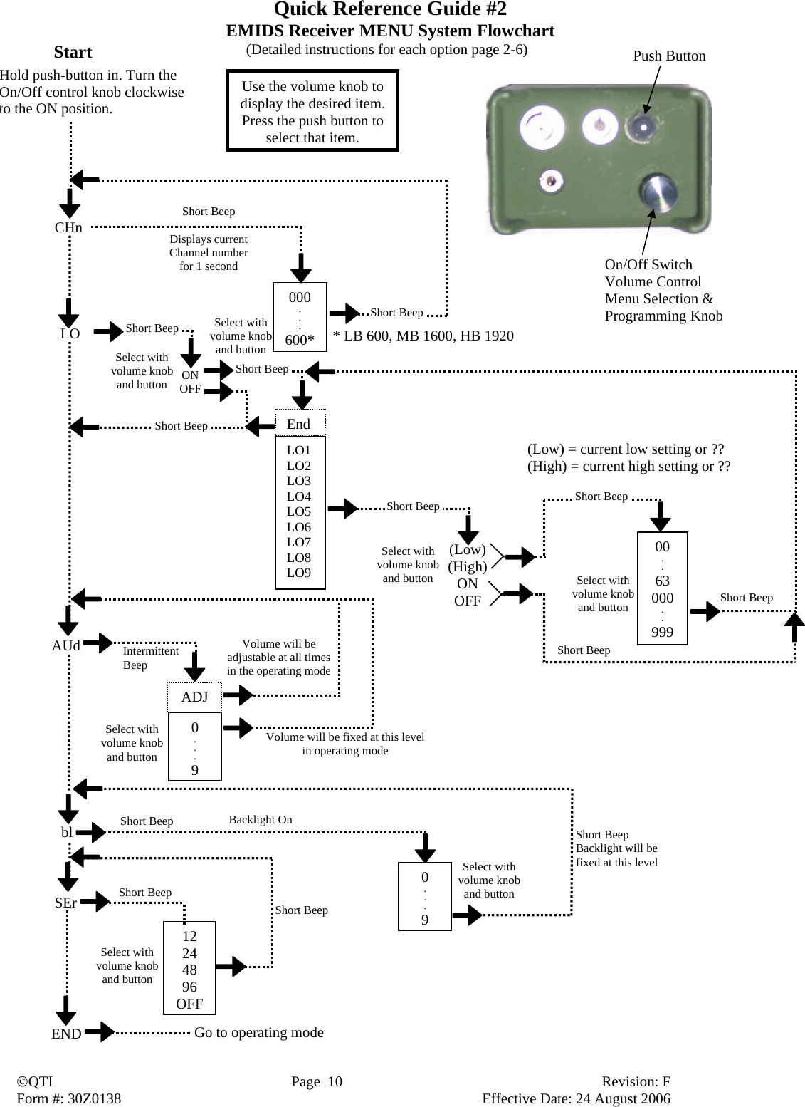
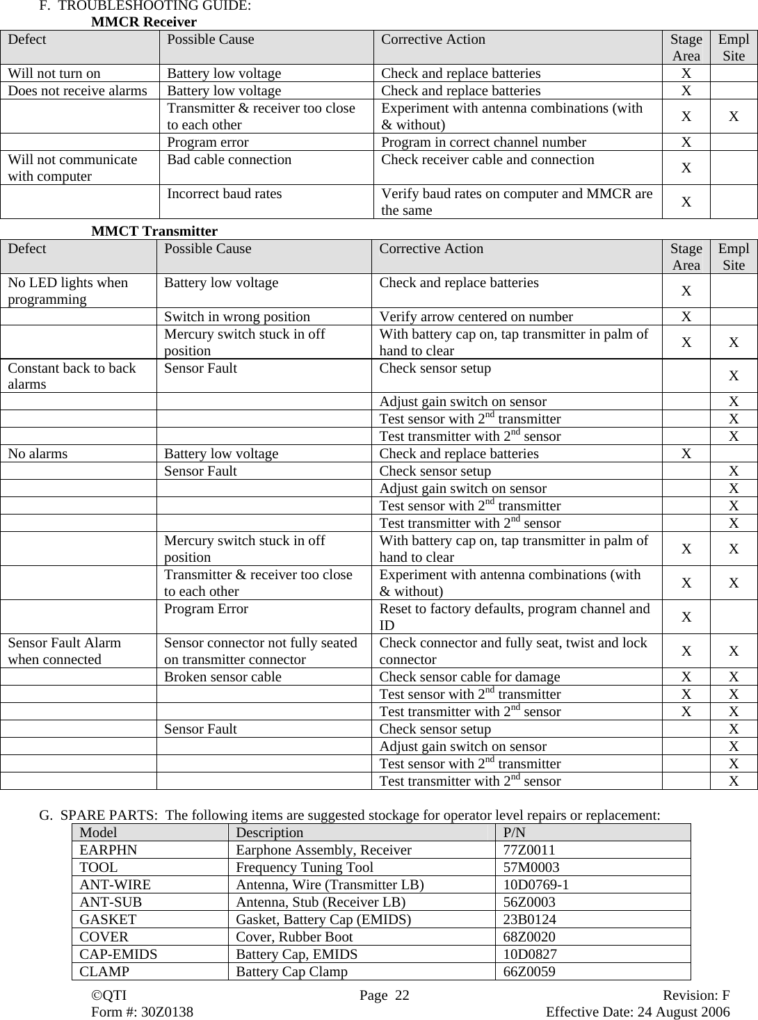
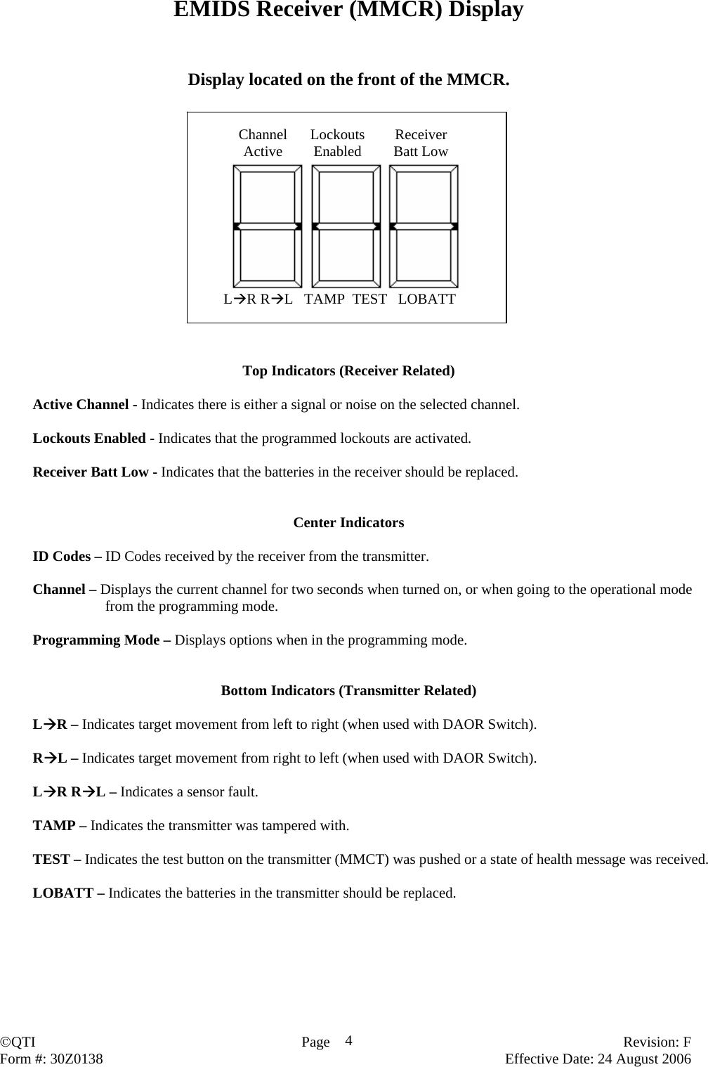
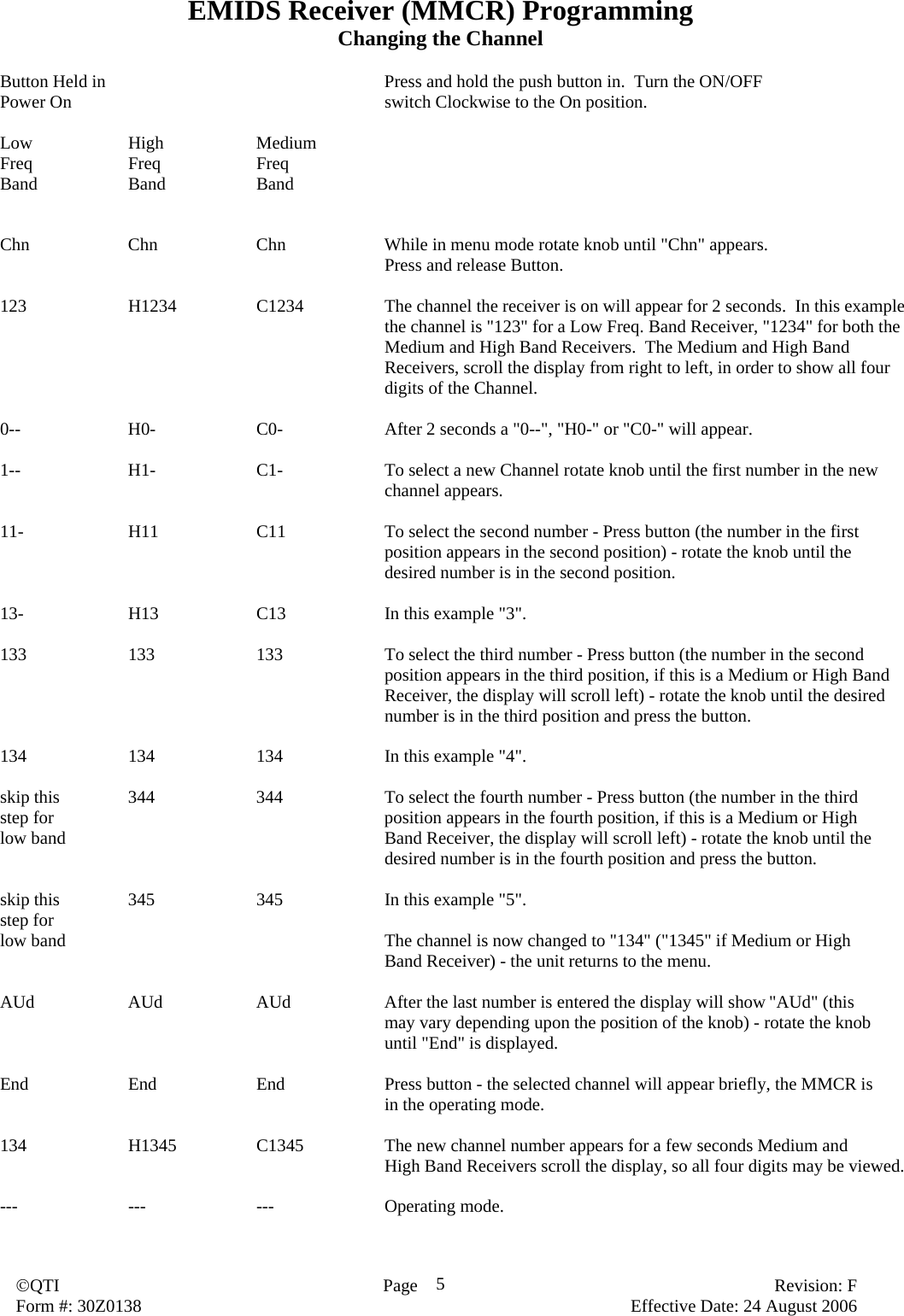
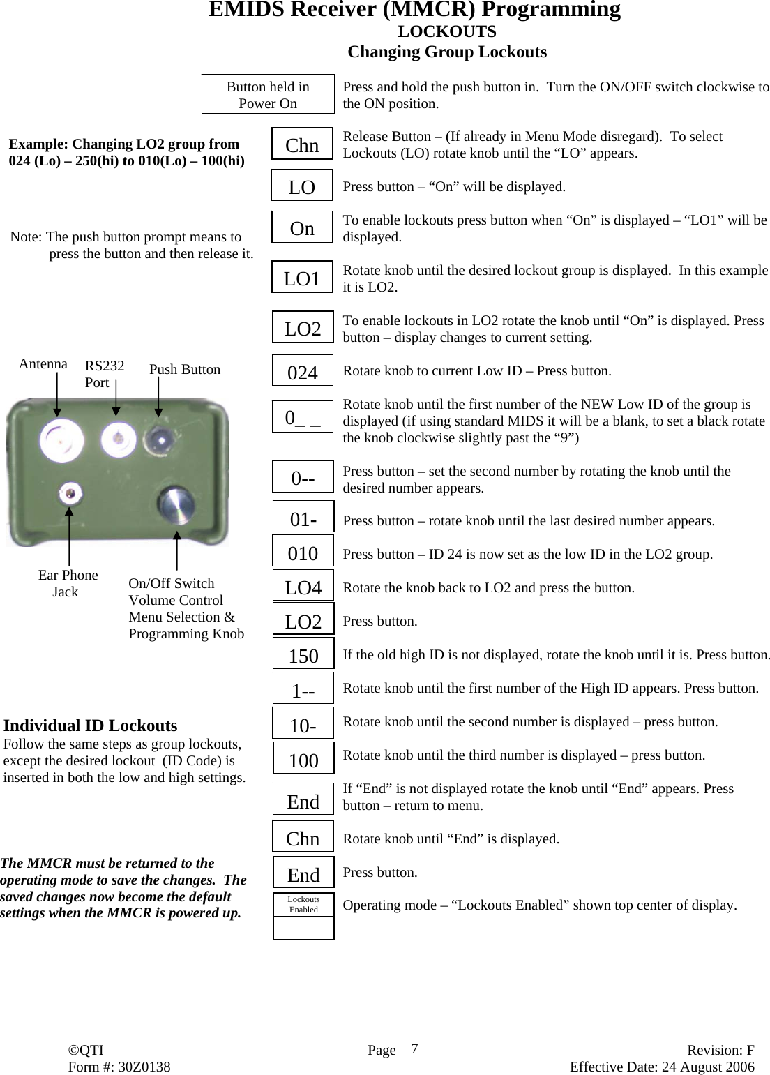
![©QTI Page Revision: F Form #: 30Z0138 Effective Date: 24 August 2006 3Section 1: EMIDS Receiver Operational Mode A receiver during normal operation will receive and decode any messages on a selectable channel. The message will be displayed as two-digit (MIDS message) or three-digit (EMIDS message). Status indicators will also be displayed with any EMIDS message received. This information may also be sent through the RS232 serial port to a remote computer/terminal. FEATURES: Displays either MIDS or EMIDS messages. Stores the last 10 messages received in memory for later recall. Available in three frequency ranges Low, Mid, and High: Low Band: 138.025-153.000 MHz @ 25 kHz steps Mid Band: 154.005-162.000 MHz @ 5.0 kHz steps High Band: 162.00625-174.000 MHz @ 6.25 kHz steps May operate on one of up to 1920 channels depending on frequency range. Low Band: 600 channels (001-600) Mid Band: 1600 channels (001-1600) High Band: 1920 channels (001-1920) ID codes may be locked out as individual ID codes or as a group of sequential codes (duty gate during hours of operation), up to 9 groups can be locked out. (Either MIDS or EMIDS). Audio level can be adjustable during operation, set to a fixed level, or turned off. A short audio tone (EMIDS only) indicates a status only message, a long audio tone indicates active alarm message. Backlight level may be off or fixed to one of nine levels. Serial interface with selectable baud rates. Many of the features may be controlled by a computer/terminal. Potted and sealed electronic components. Injection molded lexan plastic housing. Metal battery cap clamps with heat welded screw inserts. Frequency matched antenna. Sealed battery compartment. RS232 data port for interfacing with a computer. (Setup receiver as a base station receiver. Receiver MIDSComm software and receiver cable required.) Receiver Menu The Menu is accessed from the Off state. Hold the push button down and rotate the On/Off Volume knob clockwise. The receiver will turn On, and be in the Menu mode. CHn – sets the received channel number LO – sets the lockouts AUd – sets the level of the audio bl – sets the backlight level SEr – sets the serial port parameters ON/OFF Volume Control During Normal Operation the volume knob is used to turn the receiver on and off, and to adjust the audio level of the piezo (if adjustable audio is selected). During Menu Mode the volume knob is used to display the desired menu item. Push Button During Normal Operation the push button will light the backlight for 4 seconds on the first push (if the backlight is enabled), on the next push of the button (while backlight is on) the contents of memory [0] will be displayed, the next push of the button (while memory [0] is still displayed) will display memory [1] and so on through memory [9]. Memory [0] will always contain the last message received. To clear the current display, push the button and hold it in, while tilting the receiver slightly past horizontal. During the Menu Mode the push button is used to select the desired menu item. Antenna Push Button RS232 Port Ear Phone Jack On/Off Switch Volume Control Menu Selection & Programming Knob](https://usermanual.wiki/Qual-Tron/QTIEMIDSMMCT/User-Guide-776171-Page-3.png)
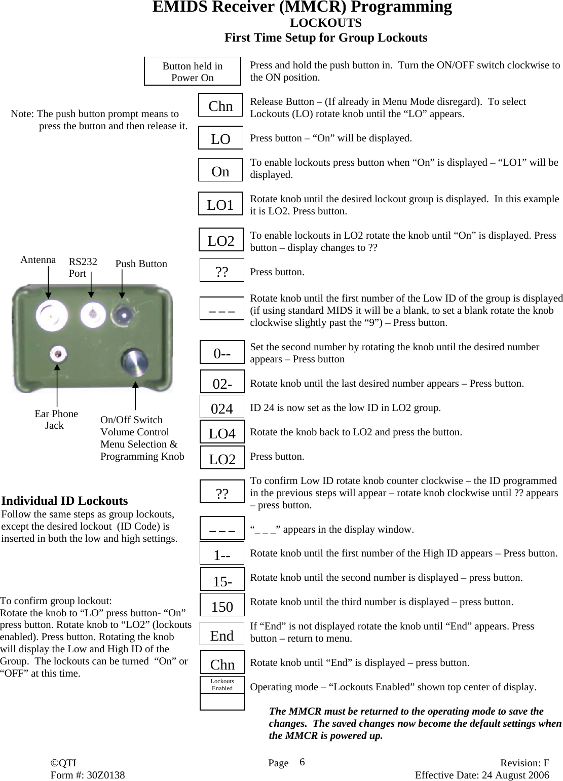
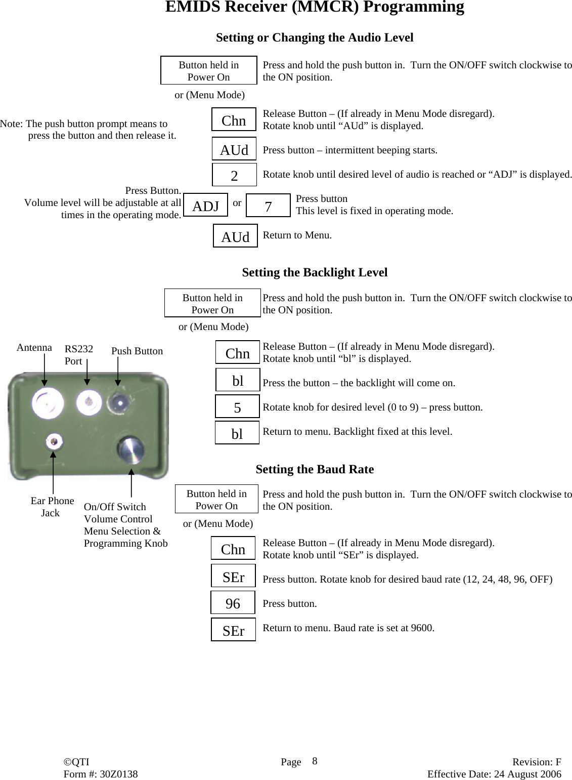
![©QTI Page Revision: F Form #: 30Z0138 Effective Date: 24 August 2006 9End Menu End Returns to operating mode Baud Rate SEr If a baud rate is selected Return to Menu. If “OFF” is selected return to Operating mode. 12 24 48 96 OFF to select option O P T I O N S Backlight Level bl Return to Menu to select option 0 1 2 3 4 5 6 7 8 9 O P T I O N S Audio Level AUd Return to Menu to select option ADJ 0 1 2 3 4 5 6 7 8 9 O P T I O N S If ADJ is selected - The audio will be adjustable in operating mode. If a number is selected - The audio level is fixed at that level in operating mode. Push Button On/Off Switch Volume Control Menu Selection & Programming Knob To access Menu: Receiver Off- Hold button in and rotate the volume on/off control to the “On” position. The receiver will power up in the Menu Mode Quick Reference Guide #1 Receiver Menu Options Detailed instructions for each option on pages 2-6 Legend Press Push-button Rotate Volume On/Off Knob Change Channel CHn Returns to Menu1st Number in new Chn ---2nd Number in new Chn 0--3rd Number in new Chn 04-4th Number in new Chn (if required) 045 456 O P T I O N S Change or Set Lockouts LO Return to Menu to select option On Off Return to Menu End LO1 LO2 LO3 LO4 LO5 LO6 LO7 LO8 LO9Return to Menu to select option Low High ON OFF End LO1 LO2 LO3 LO4 LO5 LO6 LO7 LO8 LO9 00 . . 63 000 . . 999 M I D S E M I D SSet or change three numbers for Low ID and three for High ID of the locked group. [To use with Standard MIDS (00-63), a blank is required before the two digits. (clockwise rotation slightly past the 9.)] End End Saves Changes Return to Menu To select lockout group when displayed to display lockout group](https://usermanual.wiki/Qual-Tron/QTIEMIDSMMCT/User-Guide-776171-Page-9.png)