Qual Tron QTIEMIDSMMCT MMCT – MIDS Multi Frequency Transmitter User Manual MMCT MMCR Manual 24 Aug 2006
Qual-Tron, Inc. MMCT – MIDS Multi Frequency Transmitter MMCT MMCR Manual 24 Aug 2006
User Manual
9409 E. 55th Pl. S. * Tulsa, OK 74145 * (918) 622-7052 * Fax (918) 664-8557
EMIDS Transmitter
MMCT – 13D0210 EMIDS Receiver
MMCR – 13D0209
©QTI Page Revision: F
Form #: 30Z0138 Effective Date: 24 August 2006
2
EMIDS Manual
Table of Contents
Section 1: Receiver (MMCR)
Operational Mode ……………………………………………………………………………. Page 3
Display …………………………………………………………………………………… Page 4
Changing Channels …………………………………………………………………………… Page 5
Setup Lockouts ……………………………………………………………………………... Page 6
Changing Lockouts …………………………………………………………………………… Page 7
Changing Audio Level ……………………………………………………………………….. Page 8
Changing Back Light Level …………………………………………………………………... Page 8
Setting Baud Rate …………………………………………………………………………… Page 8
Quick Ref #1 Menu Options …………………………………………………………….. Page 9
Quick Ref #2 Flow Chart …………………………………………………………….. Page 10
Section 2: Transmitter (MMCT)
Operational Mode ……………………………………………………………………………. Page 11
Initial Setup Transmitter Setup ……………………………………………………… Page 12
Program 901 Fixed Channel Mode …………………………………………………….. Page 14
Program 902 Fixed ID Mode ……………………………………………………….. Page 14
Program 903 EMIDS Format Enabled ………………………………………………… Page 15
Program 904 MIDS Format Enabled …………………………………………………. Page 15
Program 905 Fixed Mode Enabled ……………………………………………………. Page 15
Program 906 Fixed Mode Disabled …………………………………………………… Page 15
Program 907 Power Down Mode Enabled ……………………………………………. Page 15
Program 908 Power Down Mode Disabled …………………………………………... Page 16
Program 910-915 State of Health Messages (Enabled and Disabled) ……………………... Page 17
Program 930-934 Serial Port (Enabled and Disabled) …………………………………….. Page 18
Program 999 Reset to Factory Defaults ……………………………………………….. Page 19
Factory Defaults …………………………………………….……………………………….. Page 20
Section 3: Maintenance
Maintenance / Warranty …………………...…….………………………………………… Page 21
Troubleshooting …………………………………………….………………………………. Page 22
Section 4: Frequency/Channel Calculations
Frequency/Channel Table …………………...…….………………………………………… Page 23
Channel to Frequency …………………...…….…………………………………………….. Page 23
Frequency to Channel ……………………………………………………………………….. Page 23
Section 5: FCC Notice / RF Exposure
FCC Notice ……………………….………………………………………… Page 24
FCC Compliance Information …………………..…….……………………………………….. Page 24
RF Exposure ……………………………………………………………….. Page 24

©QTI Page Revision: F
Form #: 30Z0138 Effective Date: 24 August 2006
3
Section 1: EMIDS Receiver Operational Mode
A receiver during normal operation will receive and decode any messages on a selectable channel. The message will be
displayed as two-digit (MIDS message) or three-digit (EMIDS message).
Status indicators will also be displayed with any EMIDS message received. This information may also be sent through the
RS232 serial port to a remote computer/terminal.
FEATURES:
Displays either MIDS or EMIDS messages.
Stores the last 10 messages received in memory for later recall.
Available in three frequency ranges Low, Mid, and High:
Low Band: 138.025-153.000 MHz @ 25 kHz steps
Mid Band: 154.005-162.000 MHz @ 5.0 kHz steps
High Band: 162.00625-174.000 MHz @ 6.25 kHz steps
May operate on one of up to 1920 channels depending on frequency range.
Low Band: 600 channels (001-600)
Mid Band: 1600 channels (001-1600)
High Band: 1920 channels (001-1920)
ID codes may be locked out as individual ID codes or as a group of sequential
codes (duty gate during hours of operation), up to 9 groups can be locked out.
(Either MIDS or EMIDS).
Audio level can be adjustable during operation, set to a fixed level, or turned off.
A short audio tone (EMIDS only) indicates a status only message, a long audio
tone indicates active alarm message.
Backlight level may be off or fixed to one of nine levels.
Serial interface with selectable baud rates. Many of the features may be
controlled by a computer/terminal.
Potted and sealed electronic components.
Injection molded lexan plastic housing.
Metal battery cap clamps with heat welded screw inserts.
Frequency matched antenna.
Sealed battery compartment.
RS232 data port for interfacing with a computer. (Setup receiver as a base
station receiver. Receiver MIDSComm software and receiver cable required.)
Receiver Menu
The Menu is accessed from the Off state. Hold the push button down and rotate the On/Off Volume knob
clockwise. The receiver will turn On, and be in the Menu mode.
CHn – sets the received channel number
LO – sets the lockouts
AUd – sets the level of the audio
bl – sets the backlight level
SEr – sets the serial port parameters
ON/OFF Volume Control
During Normal Operation the volume knob is used to turn the receiver on and off, and to adjust the audio level of the
piezo (if adjustable audio is selected).
During Menu Mode the volume knob is used to display the desired menu item.
Push Button
During Normal Operation the push button will light the backlight for 4 seconds on the first push (if the backlight is
enabled), on the next push of the button (while backlight is on) the contents of memory [0] will be displayed, the next push
of the button (while memory [0] is still displayed) will display memory [1] and so on through memory [9]. Memory [0]
will always contain the last message received. To clear the current display, push the button and hold it in, while tilting the
receiver slightly past horizontal.
During the Menu Mode the push button is used to select the desired menu item.
Antenna Push Button
RS232
Port
Ear Phone
Jack On/Off Switch
Volume Control
Menu Selection &
Programming Knob

©QTI Page Revision: F
Form #: 30Z0138 Effective Date: 24 August 2006
4
EMIDS Receiver (MMCR) Display
Display located on the front of the MMCR.
Top Indicators (Receiver Related)
Active Channel - Indicates there is either a signal or noise on the selected channel.
Lockouts Enabled - Indicates that the programmed lockouts are activated.
Receiver Batt Low - Indicates that the batteries in the receiver should be replaced.
Center Indicators
ID Codes – ID Codes received by the receiver from the transmitter.
Channel – Displays the current channel for two seconds when turned on, or when going to the operational mode
from the programming mode.
Programming Mode – Displays options when in the programming mode.
Bottom Indicators (Transmitter Related)
LÆR – Indicates target movement from left to right (when used with DAOR Switch).
RÆL – Indicates target movement from right to left (when used with DAOR Switch).
LÆR RÆL – Indicates a sensor fault.
TAMP – Indicates the transmitter was tampered with.
TEST – Indicates the test button on the transmitter (MMCT) was pushed or a state of health message was received.
LOBATT – Indicates the batteries in the transmitter should be replaced.
Channel
Active Lockouts
Enable
d
LÆR RÆL TAMP TEST LOBATT
Receiver
Batt Low
©QTI Page Revision: F
Form #: 30Z0138 Effective Date: 24 August 2006
5
EMIDS Receiver (MMCR) Programming
Changing the Channel
Button Held in Press and hold the push button in. Turn the ON/OFF
Power On switch Clockwise to the On position.
Low High Medium
Freq Freq Freq
Band Band Band
Chn Chn Chn While in menu mode rotate knob until "Chn" appears.
Press and release Button.
123 H1234 C1234 The channel the receiver is on will appear for 2 seconds. In this example
the channel is "123" for a Low Freq. Band Receiver, "1234" for both the
Medium and High Band Receivers. The Medium and High Band
Receivers, scroll the display from right to left, in order to show all four
digits of the Channel.
0-- H0- C0- After 2 seconds a "0--", "H0-" or "C0-" will appear.
1-- H1- C1- To select a new Channel rotate knob until the first number in the new
channel appears.
11- H11 C11 To select the second number - Press button (the number in the first
position appears in the second position) - rotate the knob until the
desired number is in the second position.
13- H13 C13 In this example "3".
133 133 133 To select the third number - Press button (the number in the second
position appears in the third position, if this is a Medium or High Band
Receiver, the display will scroll left) - rotate the knob until the desired
number is in the third position and press the button.
134 134 134 In this example "4".
skip this 344 344 To select the fourth number - Press button (the number in the third
step for position appears in the fourth position, if this is a Medium or High
low band Band Receiver, the display will scroll left) - rotate the knob until the
desired number is in the fourth position and press the button.
skip this 345 345 In this example "5".
step for
low band The channel is now changed to "134" ("1345" if Medium or High
Band Receiver) - the unit returns to the menu.
AUd AUd AUd After the last number is entered the display will show "AUd" (this
may vary depending upon the position of the knob) - rotate the knob
until "End" is displayed.
End End End Press button - the selected channel will appear briefly, the MMCR is
in the operating mode.
134 H1345 C1345 The new channel number appears for a few seconds Medium and
High Band Receivers scroll the display, so all four digits may be viewed.
--- --- --- Operating mode.

©QTI Page Revision: F
Form #: 30Z0138 Effective Date: 24 August 2006
6
EMIDS Receiver (MMCR) Programming
LOCKOUTS
First Time Setup for Group Lockouts
Press and hold the push button in. Turn the ON/OFF switch clockwise to
the ON position.
Release Button – (If already in Menu Mode disregard). To select
Lockouts (LO) rotate knob until the “LO” appears.
Press button – “On” will be displayed.
To enable lockouts press button when “On” is displayed – “LO1” will be
displayed.
Rotate knob until the desired lockout group is displayed. In this example
it is LO2. Press button.
To enable lockouts in LO2 rotate the knob until “On” is displayed. Press
button – display changes to ??
Press button.
Rotate knob until the first number of the Low ID of the group is displayed
(if using standard MIDS it will be a blank, to set a blank rotate the knob
clockwise slightly past the “9”) – Press button.
Set the second number by rotating the knob until the desired number
appears – Press button
Rotate knob until the last desired number appears – Press button.
ID 24 is now set as the low ID in LO2 group.
Rotate the knob back to LO2 and press the button.
Press button.
To confirm Low ID rotate knob counter clockwise – the ID programmed
in the previous steps will appear – rotate knob clockwise until ?? appears
– press button.
“_ _ _” appears in the display window.
Rotate knob until the first number of the High ID appears – Press button.
Rotate knob until the second number is displayed – press button.
Rotate knob until the third number is displayed – press button.
If “End” is not displayed rotate the knob until “End” appears. Press
button – return to menu.
Rotate knob until “End” is displayed – press button.
Operating mode – “Lockouts Enabled” shown top center of display.
The MMCR must be returned to the operating mode to save the
changes. The saved changes now become the default settings when
the MMCR is powered up.
Button held in
Power On
Chn
LO2
On
LO
_ _ _
LO1
LO2
??
0--
02
-
024
LO4
Lockouts
Enabled
Chn
End
??
150
15
-
1
--
Note: The push button prompt means to
press the button and then release it.
Individual ID Lockouts
Follow the same steps as group lockouts,
except the desired lockout (ID Code) is
inserted in both the low and high settings.
To confirm group lockout:
Rotate the knob to “LO” press button- “On”
press button. Rotate knob to “LO2” (lockouts
enabled). Press button. Rotating the knob
will display the Low and High ID of the
Group. The lockouts can be turned “On” or
“OFF” at this time.
Antenna Push Button
RS232
Port
Ear Phone
Jack On/Off Switch
Volume Control
Menu Selection &
Programming Knob
_ _ _

©QTI Page Revision: F
Form #: 30Z0138 Effective Date: 24 August 2006
7
EMIDS Receiver (MMCR) Programming
LOCKOUTS
Changing Group Lockouts
Press and hold the push button in. Turn the ON/OFF switch clockwise to
the ON position.
Release Button – (If already in Menu Mode disregard). To select
Lockouts (LO) rotate knob until the “LO” appears.
Press button – “On” will be displayed.
To enable lockouts press button when “On” is displayed – “LO1” will be
displayed.
Rotate knob until the desired lockout group is displayed. In this example
it is LO2.
To enable lockouts in LO2 rotate the knob until “On” is displayed. Press
button – display changes to current setting.
Rotate knob to current Low ID – Press button.
Rotate knob until the first number of the NEW Low ID of the group is
displayed (if using standard MIDS it will be a blank, to set a black rotate
the knob clockwise slightly past the “9”)
Press button – set the second number by rotating the knob until the
desired number appears.
Press button – rotate knob until the last desired number appears.
Press button – ID 24 is now set as the low ID in the LO2 group.
Rotate the knob back to LO2 and press the button.
Press button.
If the old high ID is not displayed, rotate the knob until it is. Press button.
Rotate knob until the first number of the High ID appears. Press button.
Rotate knob until the second number is displayed – press button.
Rotate knob until the third number is displayed – press button.
If “End” is not displayed rotate the knob until “End” appears. Press
button – return to menu.
Rotate knob until “End” is displayed.
Press button.
Operating mode – “Lockouts Enabled” shown top center of display.
Button held in
Power On
Chn
LO
LO2
On
LO1
024
0
_
_
LO2
0--
01
-
010
LO4
150
Lockouts
Enabled
Chn
End
100
10
-
1
--
End
The MMCR must be returned to the
operating mode to save the changes. The
saved changes now become the default
settings when the MMCR is powered up.
Individual ID Lockouts
Follow the same steps as group lockouts,
except the desired lockout (ID Code) is
inserted in both the low and high settings.
Antenna Push Button
RS232
Port
Ear Phone
Jack On/Off Switch
Volume Control
Menu Selection &
Programming Knob
Note: The push button prompt means to
press the button and then release it.
Example: Changing LO2 group from
024 (Lo) – 250(hi) to 010(Lo) – 100(hi)
©QTI Page Revision: F
Form #: 30Z0138 Effective Date: 24 August 2006
8
EMIDS Receiver (MMCR) Programming
Setting or Changing the Audio Level
Press and hold the push button in. Turn the ON/OFF switch clockwise to
the ON position.
Release Button – (If already in Menu Mode disregard).
Rotate knob until “AUd” is displayed.
Press button – intermittent beeping starts.
Rotate knob until desired level of audio is reached or “ADJ” is displayed.
Press button
This level is fixed in operating mode.
Return to Menu.
Setting the Backlight Level
Press and hold the push button in. Turn the ON/OFF switch clockwise to
the ON position.
Release Button – (If already in Menu Mode disregard).
Rotate knob until “bl” is displayed.
Press the button – the backlight will come on.
Rotate knob for desired level (0 to 9) – press button.
Return to menu. Backlight fixed at this level.
Setting the Baud Rate
Press and hold the push button in. Turn the ON/OFF switch clockwise to
the ON position.
Release Button – (If already in Menu Mode disregard).
Rotate knob until “SEr” is displayed.
Press button. Rotate knob for desired baud rate (12, 24, 48, 96, OFF)
Press button.
Return to menu. Baud rate is set at 9600.
Antenna Push Button
RS232
Port
Ear Phone
Jack On/Off Switch
Volume Control
Menu Selection &
Programming Knob
Button held in
Power On
or (Menu Mode)
Chn
AU
d
2
7
ADJ
AU
d
Button held in
Power On
or (Menu Mode)
Chn
b
l
5
b
l
Button held in
Power On
or (Menu Mode)
Chn
SEr
96
SEr
Note: The push button prompt means to
press the button and then release it.
Press Button.
Volume level will be adjustable at all
times in the operating mode. or
©QTI Page Revision: F
Form #: 30Z0138 Effective Date: 24 August 2006
9
End Menu
End
Returns to
operating
mode
Baud Rate
SEr
If a baud rate is
selected Return to
Menu. If “OFF” is
selected return to
O
p
eratin
g
mode.
12
24
48
96
OFF
to select
option
O
P
T
I
O
N
S
Backlight
Level
bl
Return to
Menu
to select
option
0
1
2
3
4
5
6
7
8
9
O
P
T
I
O
N
S
A
ud
i
o
L
eve
l
AUd
Return to
Menu
to select
option
ADJ
0
1
2
3
4
5
6
7
8
9
O
P
T
I
O
N
S
If ADJ is selected -
The audio will be
adjustable in
operating mode.
If a number is
selected - The audio
level is fixed at that
level in operating
mode.
Push Button
On/Off Switch
Volume Control
Menu Selection &
Programming Knob
To access Menu:
Receiver Off- Hold button in and rotate
the volume on/off control to the “On”
position. The receiver will power up in
the Menu Mode
Quick Reference Guide #1
Receiver Menu Options
Detailed instructions for each option on pages 2-6
Legend
Press Push-button
Rotate Volume On/Off Knob
Change
Channel
CHn
Returns to
Menu
1s
t
Number
in new Chn
---
2n
d
Number
in new Chn
0
--
3
r
d
Number
in new Chn
04
-
4th Number
in new Chn
(if required)
045
456
O
P
T
I
O
N
S
Change or Set
Lockouts
LO
Return to Menu
to select
option
On
Off Return to
Menu
End
LO1
LO2
LO3
LO4
LO5
LO6
LO7
LO8
LO9
Return to
Menu
to select
option
Low
High
ON
OFF End
LO1
LO2
LO3
LO4
LO5
LO6
LO7
LO8
LO9
00
.
.
63
000
.
.
999
M
I
D
S
E
M
I
D
S
Set or change three numbers
for Low ID and three for
High ID of the locked group.
[To use with Standard MIDS
(00-63), a blank is required
before the two digits.
(clockwise rotation slightly
p
ast the 9.
)]
End
End
Saves Chan
g
es
Return to Menu
To select
lockout group
when dis
p
la
y
e
d
to display
lockout
group
©QTI Page 10 Revision: F
Form #: 30Z0138 Effective Date: 24 August 2006
Quick Reference Guide #2
EMIDS Receiver MENU System Flowchart
(Detailed instructions for each option page 2-6)
Select with
volume knob
and button
AU
d
ADJ
0
.
.
.
9
Select with
volume knob
and button
Volume will be
adjustable at all times
in the operating mode
Volume will be fixed at this level
in operating mode
Intermittent
Bee
p
SE
r
12
24
48
96
OFF
END
Short Beep
Short Beep
Go to operating mode
b
l Short Beep Backlight On
0
.
.
.
9
Select with
volume knob
and button
Short Beep
Backlight will be
fixed at this level
00
.
.
63
000
.
.
999
(Low)
(High)
ON
OFF
Select with
volume knob
and button
Short Beep
Select with
volume knob
and button Short Beep
Short Beep
Short Beep En
d
Short Beep
* LB 600, MB 1600, HB 1920
Push Button
On/Off Switch
Volume Control
Menu Selection &
Programming Knob
Start
Hold push-button in. Turn the
On/Off control knob clockwise
to the ON position.
Use the volume knob to
display the desired item.
Press the push button to
select that item.
CHn Short Beep
Displays current
Channel number
for 1 second
000
.
.
.
600*
Select with
volume knob
and button
Short Beep
LO1
LO2
LO3
LO4
LO5
LO6
LO7
LO8
LO9
LO Short Beep
Select with
volume knob
and button
(Low) = current low setting or ??
(High) = current high setting or ??
Short Beep
ON
OFF
©QTI Page 11 Revision: F
Form #: 30Z0138 Effective Date: 24 August 2006
Section 2: EMIDS Transmitter (MMCT) Operational Mode
Channel: Low Band: 25 kHz spacing (600 channels)
Mid Band: 5 kHz spacing (1600 channels)
High Band: 6.25 kHz spacing (1920 channels)
ID Code: 0-999 per RF Channel
Antenna: ¼ wire whip
RF Output: Nominal 1 Watt
Frequency Range: Low Band: 138.025-153.000 MHz
Mid Band: 154.005-162.000 MHz
High Band: 162.00625-174.000 MHz
Power Supply: 4 commercial 9 volt (MN1604)
Battery Life: 4-6 months @ 25° C
Sensor: Any MIDS sensor can be used with this
transmitter. With special instructions
additional sensors can also be used.
Pin Connection: A: Ground
B: +9 VDC
C: Tx Trigger
D: ID Code Control (Do not use)
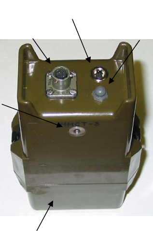
Description
Normal operation for the transmitter is to receive, process and transmit via RF frequencies, data from various types of attached
ground sensors. The transmitter frequency is selectable via synthesizer control circuits providing a selection of up to 1920 RF
channels, depending on frequency range, to choose from:
Low Band Mid Band High Band
Channel 001 = 138.025 MHz Channel 001 = 154.005 MHz Channel 001 = 162.00625 MHz
Channel 600 = 153.000 MHz Channel 1600 = 162.000 MHz Channel 1920 = 174.000 MHz
Design Features:
ID Code Selection 001-999
Internal power ON – normal operation – antenna up
Internal power OFF – non operating – battery cap up
Internal power ON – align (sensor set) – battery cap down
Transmit ID Code Alarms
Transmit State-Of-Health-Messages
Directional information (L>R, R>L)
Sensor fault (when both are on at the same time)
Tamper
Test
Low Battery
Three switches for programming operation functions
A Tri colored LED used to confirm programming process functions
A sealed battery compartment
An RS-232 data port for interfacing with a computer
Potted and sealed electronic components
Injection molded plastic housing
Metal battery cap clamps with heat welded screw inserts
Frequency matched antenna
During normal operation the transmitter may be triggered by an external sensor through its sensor connection. A message will
then be transmitted on a selected channel. A message may also be initiated with the push button on the top unit. The unit may
be put in the align mode by placing it with the battery cap down. Power is turned off by placing the unit with the battery cap
up. Power will remain on for five minutes after it is initially applied.
Sensor
Connecto
r
RS232 Test
Button
Antenna
Connecto
r
Battery Cap
©QTI Page 12 Revision: F
Form #: 30Z0138 Effective Date: 24 August 2006
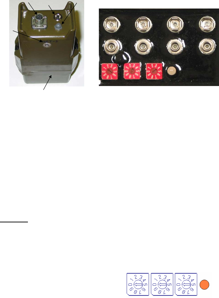
Section 2: EMIDS Transmitter (MMCT) Operational Mode
MMCT Battery Compartment
9 volt Battery connectors
Rotary Switches Tri-Colored LED
Initial Transmitter Set Up
Set up of the transmitter consists of selecting the desired channel number, the desired ID number and the desired modes of
operation. This is accomplished with the three rotary switches in the battery compartment and the push button on the top of
the transmitter. These rotary switches are used to set up the transmitter. After set up they are used to inform the transmitter
the ID number or the channel number depending on the mode of operation selected. A tri-colored LED is provided to give the
operator feed back during the set up of the transmitter.
LED Amber – the unit is waiting for an entry
LED Green – indicates that the set up was accepted
LED Red – indicates an incorrect entry
Items required:
Power Source: One (1) to four (4) 9-volt MN1604 Duracell “copper top” batteries.
Tool: One R3322 Small Xcelite or equivalent screwdriver.
Receiver: One MMCR – to confirm transmitter operations.
The following is a list of programming codes and their functions. After the setup is complete, the rotary switches should
not be left in the position 000. The position 000 is reserved for programming mode only, this causes the unit to go into
programming mode for one minute to allow entry of the set up codes. After the one-minute is up, the unit goes back to the
normal operating mode. Entry of a set up code after the one minute will result in the transmission of a test message, no
programming will occur.
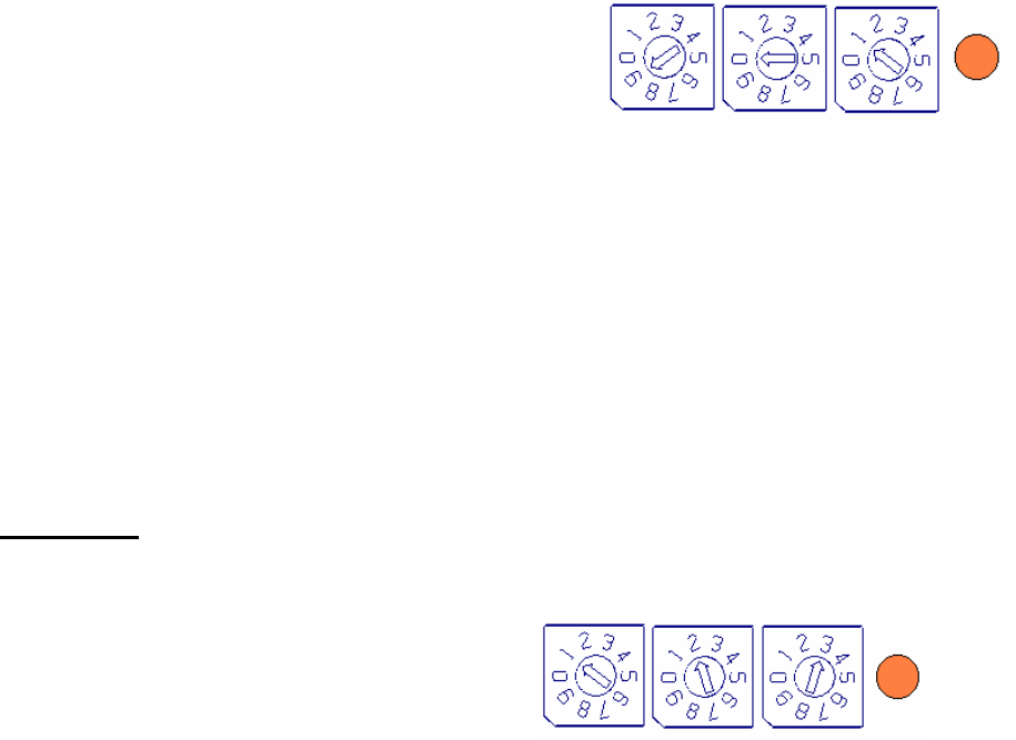
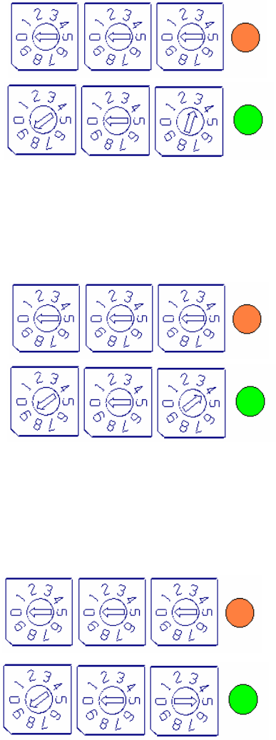
STEP ONE: Initial Channel Set-Up
NOTE: The channel number may be 001-600 for LB, 001-1600 for MB, or 001-1920 for HB. Channel number 000 should
not be used.
1. Remove the battery cap and install 1-4 new 9-volt batteries (see battery compartment above) (When power is first applied,
the unit will stay on for five minutes whatever its position.)
2. Hold the transmitter to view the switches – the transmitter should be in a level position with the antenna terminal up.
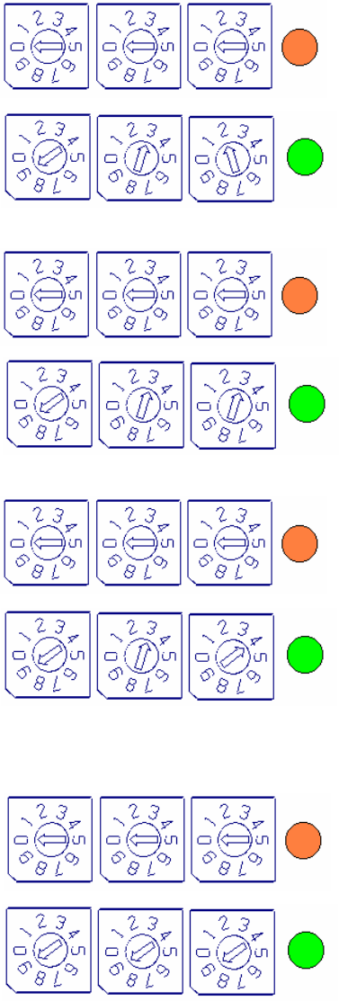
3. Set each switch to the “0” position. Press and release the
test button (on top of the transmitter) once – the LED should
be amber. The unit is now in the programming mode, and
the next selection must be made within one minute.
Sensor
Connecto
r
RS232
Test
Button
Antenna
Connecto
r
Battery Cap
Amber
©QTI Page 13 Revision: F
Form #: 30Z0138 Effective Date: 24 August 2006
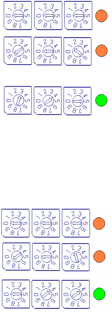
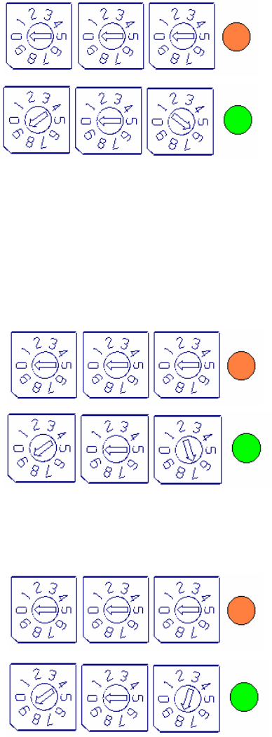
EMIDS Transmitter (MMCT) Programming
4. Set the switches to “901” for Low Band channels 001-600,
Set the switches to “920” for High Band channels 001-999,
Set the switches to “921” for High Band channels 1000-1920,
Set the switches to “950” for Mid Band channels 001-999, or
Set the switches to “951” for Mid Band channels 1000-1600.
5. Press and release the test button.
6. Set the three switches to the desired channel number. (For MB and HB channels over 999, use only the last three digits).
7. Press and release the test button. (The LED will change to Green when correct or to Red for incorrect switch positions or
if delays in meeting time limits to make changes).
8. If the LED is Green, press and release the test button to transmit a test message to the receiver and confirm operation of
both units.
9. If the LED is Red, start the procedure over starting at step 3 and continue through step 8 until a Green LED is obtained,
then test.
STEP TWO Initial ID Code Set-Up
NOTE: The ID Code may be 001-999 in the EMIDS mode, or 01-63 in the MIDS mode.
1. Set Switches to the three number ID code for each
transmitter/sensor used for the specific application.
(In this example, 123)
2. For ease of identifying transmitters, before deployment, apply a piece of tape to the transmitter (not the battery cap) and
mark the ID code on the tape.
3. To test the tamper alarm, lay the transmitter flat with the antenna port up for five minutes, then pick up the transmitter,
observe the tamper alarm on the receiver to verify it displayed a warning that the transmitter has been disturbed.
4. Important: While the battery cap is off, keep the transmitter free of dirt and water. Clean the gasket area before installing
the battery cap.
5. Replace battery cap and snap clamps shut. Make sure black rubber plug is installed to protect the RS-232 data port.
6. The antenna and sensor may now be installed or they may be attached at the deployment site. The transmitter should lay
as flat as possible to prevent it from being turned off or activating tamper switches.
LED
Blinks
Remains
Amber
©QTI Page 14 Revision: F
Form #: 30Z0138 Effective Date: 24 August 2006
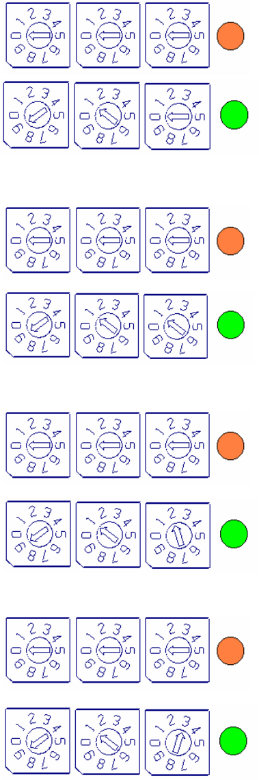
EMIDS Transmitter (MMCT) Programming
Program 901: Fixed Channel Mode (Changing the channel after initial set-up)
Program 901 is used for Low Frequency Band transmitters, Channels 001-600.
For High Frequency Band transmitters, Channels 001-999, use Program 920.
For High Frequency Band transmitters, Channels 1000-1920, use Program 921.
For Medium Frequency Band transmitters, Channels 001-999, use Program 950.
For Medium Frequency Band transmitters, Channels 1000-1600, use Program 951.
1. Set the switches to “000” – Press and release the test
button, the LED should turn to Amber. The unit is now in
the programming mode.
2. Set the switches to “901” for LB channels 001-600 (or
other corresponding program number as described above)
– Press and release the test button, the LED should blink
once and return to Amber. The unit is ready to accept the
channel number.
3. Set the switches to the desired channel number. (In this
example “345”). Press and release the test button, the LED
should turn Green for two seconds. Channel “345” is
selected.
NOTE 1: If the LED is Red at the end of step 3, an error has occurred. Repeat the procedure, otherwise no
programming will occur.
NOTE 2: The channel number may be 001- 600 for LB, 001-1600 for MB, or 001-1920 for HB. Channel number 000
should not be used.
Program 902: Fixed ID Mode (Changes and locks in transmitter identification code)
NOTE: The ID number may be 001-999. In the EMIDS Mode, or 01-63 in the MIDS Mode.
1. Set the switches to “000” – Press and release the test
button, the LED should turn to Amber. The unit is now in
the programming mode.
2. Set the switches to “902” – Press and release the test
button, the LED should blink once and return to Amber.
The unit is ready to accept the ID number.
3. Set the switches to the desired ID number. (In this example
“044”). Press and release the test button, the LED should
turn Green for two seconds. ID Code “044” is set.
For ease of identifying transmitters, before deployment, apply a piece of tape to the transmitter (not the battery cap) and mark
the ID code on the tape.
Amber
Blinks
Remains
Amber
Green - OK
Red - Error
Amber
Green - OK
Red - Error
Blinks
Remains
Amber
©QTI Page 15 Revision: F
Form #: 30Z0138 Effective Date: 24 August 2006
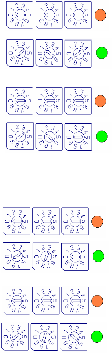
EMIDS Transmitter (MMCT) Programming
Program 903: EMIDS Format Enabled (Used when EMIDS (MMCT) transmitters are deployed)
The EMIDS format allows the use of all the added features of the EMIDS transmitter. (See page two for details).
1. Set the switches to “000” – Press and release the test
button. The LED should turn to Amber. The unit is
now in the programming mode.
2. Set the switches to “903” – Press and release the test
button, the LED should turn to Green for two
seconds. This will enable the EMIDS format.
Program 904: MIDS Format Enabled (Used when standard MIDS transmitters (MXMT) are deployed)
The MIDS format allows the EMIDS transmitter to emulate a standard MIDS transmitter. This mode only transmits two
digit ID codes and status messages are not transmitted. This is done to reduce false alarms when using MIDS transmitters
(MXMT).
1. Set the switches to “000” – Press and release the test
button. The LED should turn to Amber. The unit is
now in the programming mode.
2. Set the switches to “904” – Press and release the test
button, the LED should turn to Green for two
seconds. This will enable the MIDS format.
Program 905: Fixed Mode Enabled (Locks in the channel number and the ID code)
The fixed mode allows both the channel number and the ID number to be fixed. This prevents unauthorized tampering
from changing the channel or ID number of the transmitter. The channel number will be the last channel number entered
in the fixed channel mode. The ID number will be the last ID number entered in the fixed ID mode.
This information should be entered before entering the fixed mode of operation.
1. Set the switches to “000” – Press and release the test
button. The LED should turn to Amber. The unit is
now in the programming mode.
2. Set the switches to “905” – Press and release the test
button, the LED should turn to Green for two
seconds. This will enable the Fixed mode.
Amber
Amber
Amber
Turns
Green
for 2 Sec
Turns
Green
for 2 Sec
Turns
Green
for 2 Sec
©QTI Page 16 Revision: F
Form #: 30Z0138 Effective Date: 24 August 2006
EMIDS Transmitter (MMCT) Programming
Program 906: Fixed Mode Disabled
1. Set the switches to “000” – Press and release the test
button. The LED should turn to Amber. The unit is
now in the programming mode.
2. Set the switches to “906” – Press and release the test
button, the LED should turn to Green for two
seconds. The Fixed Mode is disabled.
Program 907: Power Down Mode Enabled
Warning: If the serial port is being used, this mode should be disabled to prevent the loss of communications
when the power down mode is activated.
The Power Down Mode puts the transmitter into a sleep mode five minutes after the transmitter is turned on. The
transmitter will revert to normal mode when triggered by a sensor. This mode will extend battery life, and should
be enabled when the unit is placed in the field.
1. Set the switches to “000” – Press and release the test
button. The LED should turn to Amber. The unit is
now in the programming mode.
2. Set the switches to “907” – Press and release the test
button, the LED should turn to Green for two
seconds. The Power Down Mode is enabled.
Program 908: Power Down Mode Disabled
Program 908 should be entered whenever the serial port is being used to program transmitters
1. Set the switches to “000” – Press and release the test
button. The LED should turn to Amber. The unit is
now in the programming mode.
2. Set the switches to “908” – Press and release the test
button, the LED should turn to Green for two
seconds. The Power Down Mode is disabled.
Amber
Amber
Amber
Turns
Green
for 2 Sec
Turns
Green
for 2 Sec
Turns
Green
for 2 Sec
©QTI Page 17 Revision: F
Form #: 30Z0138 Effective Date: 24 August 2006
EMIDS Transmitter (MMCT) Programming
Program 910 to 915: State of Health Messages
A State-of-Health message, depending on the program, will be transmitted. This message confirms that the transmitter is
working properly. “Test” will be displayed on the receiver display along with the ID code of the transmitter.
Every Hour (910)
1. Set the switches to “000” – Press and release the test
button. The LED should turn to Amber. The unit is
now in the programming mode.
2. Set the switches to “910” – Press and release the test
button, the LED should turn to Green for two
seconds. A State of Health Message will be sent
every hour.
Every Two Hours (911)
1. Set the switches to “000” – Press and release the test
button. The LED should turn to Amber. The unit is
now in the programming mode.
2. Set the switches to “911” – Press and release the test
button, the LED should turn to Green for two
seconds. A State of Health Message will be sent
every two hours.
Every Six Hours (912)
1. Set the switches to “000” – Press and release the test
button. The LED should turn to Amber. The unit is
now in the programming mode.
2. Set the switches to “912” – Press and release the test
button, the LED should turn to Green for two
seconds. A State of Health Message will be sent
every six hours.
Every Twelve Hours (913)
1. Set the switches to “000” – Press and release the test
button. The LED should turn to Amber. The unit is
now in the programming mode.
2. Set the switches to “913” – Press and release the test
button, the LED should turn to Green for two
seconds. A State of Health Message will be sent
every twelve hours.
Amber
Turns
Green
for 2 Sec
Amber
Turns
Green
for 2 Sec
Amber
Turns
Green
for 2 Sec
Amber
Turns
Green
for 2 Sec
©QTI Page 18 Revision: F
Form #: 30Z0138 Effective Date: 24 August 2006
EMIDS Transmitter (MMCT) Programming
State of Health Messages (cont.)
Every Twenty-Four Hours (914)
1. Set the switches to “000” – Press and release the test
button. The LED should turn to Amber. The unit is
now in the programming mode.
2. Set the switches to “914” – Press and release the test
button, the LED should turn to Green for two
seconds. A State of Health Message will be sent
every twenty-four hours.
State of Health Messages Disabled (915)
1. Set the switches to “000” – Press and release the test
button. The LED should turn to Amber. The unit is
now in the programming mode.
2. Set the switches to “915” – Press and release the test
button, the LED should turn to Green for two
seconds. A State of Health Message are disabled.
Program 930 to 934: Serial Port Baud Rates
These programs are used to set the baud rate of the serial port.
Warning: If the serial port is activated, the power down option must be disabled. (See Program 908)
Baud Rate 9600 (930)
1. Set the switches to “000” – Press and release the test
button. The LED should turn to Amber. The unit is
now in the programming mode.
2. Set the switches to “930” – Press and release the test
button, the LED should turn to Green for two
seconds. Baud rate is set at 9600.
Baud Rate 4800 (931)
1. Set the switches to “000” – Press and release the test
button. The LED should turn to Amber. The unit is
now in the programming mode.
2. Set the switches to “931” – Press and release the test
button, the LED should turn to Green for two
seconds. Baud rate is set at 4800.
Amber
Turns
Green
for 2 Sec
Amber
Turns
Green
for 2 Sec
Amber
Turns
Green
for 2 Sec
Amber
Turns
Green
for 2 Sec
©QTI Page 19 Revision: F
Form #: 30Z0138 Effective Date: 24 August 2006
EMIDS Transmitter (MMCT) Programming
Serial Port Baud Rates (cont.)
Baud Rate 2400 (932)
1. Set the switches to “000” – Press and release the test
button. The LED should turn to Amber. The unit is
now in the programming mode.
2. Set the switches to “932” – Press and release the test
button, the LED should turn to Green for two
seconds. Baud rate is set at 2400.
Baud Rate 1200 (933)
1. Set the switches to “000” – Press and release the test
button. The LED should turn to Amber. The unit is
now in the programming mode.
2. Set the switches to “933” – Press and release the test
button, the LED should turn to Green for two
seconds. Baud rate is set at 1200.
Serial Port Disabled (934)
1. Set the switches to “000” – Press and release the test
button. The LED should turn to Amber. The unit is
now in the programming mode.
2. Set the switches to “934” – Press and release the test
button, the LED should turn to Green for two
seconds. The serial port is turned off to conserve
battery life.
Program 999: Reset to Factory Defaults
1. Set the switches to “000” – Press and release the test
button. The LED should turn to Amber. The unit is
now in the programming mode.
2. Set the switches to “999” – Press and release the test
button, the LED should turn to Green for two
seconds. The transmitter is reset to the factory
defaults.
Amber
Turns
Green
for 2 Sec
Amber
Turns
Green
for 2 Sec
Amber
Turns
Green
for 2 Sec
Amber
Turns
Green
for 2 Sec
©QTI Page 20 Revision: F
Form #: 30Z0138 Effective Date: 24 August 2006
EMIDS Transmitter (MMCT) Programming
Reset to Factory Defaults
The factory Reset allows the transmitter to be programmed to a known condition.
Factory Defaults
Fixed Channel Mode Enabled Channel # 000
Fixed ID Mode Disabled
EMIDS Format Enabled
MIDS Format Disabled
Fixed Mode Disabled
Power Down Mode Enabled
Serial Port Disabled
State-of-Health 24 Hours

©QTI Page 21 Revision: F
Form #: 30Z0138 Effective Date: 24 August 2006
Section 3: Maintenance
Recommended Battery: QTI recommends four (4) batteries based on past experience and the ability to peak rapidly.
Duracell Coppertop Alkaline MN1604
Duracell Procell Alkaline PC1604
Kodak Alkaline 6LR61
Ultralife Lithium U9VL-J (MMCR Only)
MAINTENANCE:
A. OPERATOR MAINTENANCE:
The EMIDS equipment has been designed as low cost low maintenance equipment. All components are potted
and sealed which reduces the amount of maintenance required. The only required operator maintenance is to inspect the
equipment for damage and keep the equipment clean of dirt, grime, and caked on mud.
• Outside Case Maintenance: Remove large clumps of mud with a brush or by hand. Use a dry soft cloth to remove
any remaining residue or dirt. NOTE: Do not submerge the equipment in water. This could result in damage.
• Display Maintenance: Remove excess dirt with soft brush and blow material away. Then clean the display surface
with a damp cloth.
• Connector Inspection: Check connector cavities for dirt and obstructions. If present, remove obstructions.
• Battery Cap Inspection: Remove the battery cap and inspect the gasket and sealing surface. Replace the gasket if
cracked or damaged. Remove any dirt or grime from both mating surfaces with a damp cloth. Lubricate the gasket
with a silicon based lubricant to keep it soft and prevent cracking.
• Battery Terminals: Inspect battery terminals for bent terminals. If bent, straighten with needle nose pliers. Note:
Do not work the terminal back and forth as this might cause the terminal to break.
B. DEPOT MAINTENANCE: Upper echelon maintenance will be performed by the supplier of the equipment. If the
equipment is beyond the user capability to repair, it can be returned to the supplier for test and evaluation. Upon
completion of the inspection, the supplier will notify the user if the unit can be repaired. If the equipment is not covered
by the warranty, an estimate will be provided for repair costs. If the equipment is not repairable, the supplier will specify
replacement costs. (Note: See warranty below for return procedures.)
C. EQUIPMENT STORAGE: Upon return to the facility, clean equipment as noted in operator maintenance above.
Remove batteries from all equipment to prevent possible damage. If batteries are left in the equipment, transmitters will
continue to send fault alarms every 10 minutes causing a continuous drain on the batteries and possibly resulting in
damaged or ruptured batteries. After cleaning, return the equipment to the storage cases. Store in a dry, room temperature
environment.
D. WARRANTY:
Qual-Tron, Inc. guarantees all products to be free from defects in materials and workmanship for 12 months from the date
of purchase. Damage due to misuse, accidents, lightning strikes, unauthorized service, environmental conditions beyond
the equipment specifications, acts of war or damage other than fair, wear and tear is excluded from this warranty.
E. RETURN PROCEDURES:
For support and service, please contact the following. To return any material, contact Qual-Tron, Inc. to receive a Return
Material Authorization (RMA) number. Once an RMA number has been assigned, ship the material to the address below
and reference the RMA number on the packing slip. Qual-Tron will return the equipment as quickly as possible to the
user.
QUAL-TRON, INC.
Attn: Sales Ph: 918-622-7052
9409 E. 55th Place Fax: 918-664-8557
Tulsa, OK 74145 email: sales@qual-tron.com

©QTI Page 22 Revision: F
Form #: 30Z0138 Effective Date: 24 August 2006
F. TROUBLESHOOTING GUIDE:
MMCR Receiver
Defect Possible Cause Corrective Action Stage
Area Empl
Site
Will not turn on Battery low voltage Check and replace batteries X
Does not receive alarms Battery low voltage Check and replace batteries X
Transmitter & receiver too close
to each other Experiment with antenna combinations (with
& without) X X
Program error Program in correct channel number X
Will not communicate
with computer Bad cable connection Check receiver cable and connection X
Incorrect baud rates Verify baud rates on computer and MMCR are
the same X
MMCT Transmitter
Defect Possible Cause Corrective Action Stage
Area Empl
Site
No LED lights when
programming Battery low voltage Check and replace batteries X
Switch in wrong position Verify arrow centered on number X
Mercury switch stuck in off
position With battery cap on, tap transmitter in palm of
hand to clear X X
Constant back to back
alarms Sensor Fault Check sensor setup X
Adjust gain switch on sensor X
Test sensor with 2nd transmitter X
Test transmitter with 2nd sensor X
No alarms Battery low voltage Check and replace batteries X
Sensor Fault Check sensor setup X
Adjust gain switch on sensor X
Test sensor with 2nd transmitter X
Test transmitter with 2nd sensor X
Mercury switch stuck in off
position With battery cap on, tap transmitter in palm of
hand to clear X X
Transmitter & receiver too close
to each other Experiment with antenna combinations (with
& without) X X
Program Error Reset to factory defaults, program channel and
ID X
Sensor Fault Alarm
when connected Sensor connector not fully seated
on transmitter connector Check connector and fully seat, twist and lock
connector X X
Broken sensor cable Check sensor cable for damage X X
Test sensor with 2nd transmitter X X
Test transmitter with 2nd sensor X X
Sensor Fault Check sensor setup X
Adjust gain switch on sensor X
Test sensor with 2nd transmitter X
Test transmitter with 2nd sensor X
G. SPARE PARTS: The following items are suggested stockage for operator level repairs or replacement:
Model Description P/N
EARPHN Earphone Assembly, Receiver 77Z0011
TOOL Frequency Tuning Tool 57M0003
ANT-WIRE Antenna, Wire (Transmitter LB) 10D0769-1
ANT-SUB Antenna, Stub (Receiver LB) 56Z0003
GASKET Gasket, Battery Cap (EMIDS) 23B0124
COVER Cover, Rubber Boot 68Z0020
CAP-EMIDS Battery Cap, EMIDS 10D0827
CLAMP Battery Cap Clamp 66Z0059

©QTI Page 23 Revision: F
Form #: 30Z0138 Effective Date: 24 August 2006
Section 4: Frequency/Channel Calculations
Frequency Ranges
Frequency Frequency
Range Min Max
Channel
Steps Max
Channels
Low 138 MHz 153 MHz 25 kHz 600
Mid 154 MHz 162 MHz 5 kHz 1600
High 162 MHz 174 MHz 6.25 kHz 1920
Channel to Frequency Calculation
Channel * Channel Step + Min Frequency = Frequency for Channel
Examples:
- Low Band Channel 20
- 20 * 0.025 +138 =138.5 MHz
- Mid Band Channel 300
- 300 * 0.005 + 154 = 155.5 MHz
Frequency to Channel Calculation
(Frequency – Min Frequency) / Channel Step = Channel for Frequency
Examples:
- Low Band 151.5 MHz
- (151.5 – 138) / 0.025 = Channel 540
- High Band 172.5 MHz
- (172.5 – 162) / 0.00625 = Channel 1680
©QTI Page 24 Revision: F
Form #: 30Z0138 Effective Date: 24 August 2006
Section 5: FCC Notice / RF Exposure
FCC Notices (U.S. Only)
This equipment has been tested and found to comply with the limits for a Class B digital device pursuant to Part 15 of the
FCC Rules. These limits are designed to provide reasonable protection against harmful interference when the equipment
is operated in a residential installation. This equipment generates, uses and can radiate radio frequency energy and if not
installed and used in accordance with the manufacturer’s instruction manual, may cause interference with radio
communications. However there is no guarantee that interference will not occur in a particular installation. If this
equipment does cause harmful interference to radio or television reception, which can be determined by turning the
equipment off and on, you are encouraged to try to correct the interference by one or more of the following measures:
- Reorient or relocate the receiving antenna.
- Increase the separations between the equipment and receiver
- Connect the equipment into an outlet on a circu8it different from that to which the receiver is connected
- Consult the dealer or experience radio/TV technician for help.
FCC Compliance Information
The following information is provided on the device or devices covered in this document in compliance with FCC
regulations:
• Model Number: QTIEMIDSMMCT, QTIEMIDSMMCR
• Company Name:
Qual-Tron, Inc.
9409 E. 55th Pl. S.
Tulsa, OK 74145-8157 USA
918-622-7052
RF Exposure – MPE / SAR
“For body worn operation”, the MMCR has been tested and meets the FCC RF exposure guidelines when used with the
Qual-Tron, Inc. accessories (to include batteries) supplied or designated for this product, and provided at least 10 cm
separation between device including its antenna and the user’s body is maintained. Use of other accessories may not
ensure compliance with FCC RF exposure guidelines.
In order to comply with FCC RF Exposure requirements, the MMCT device must be installed and operated in such a way
that a minimum separation distance of 20cm is always maintained between the antenna and all persons during normal
operations.