Qual Tron QTIMIDSMCDT 138-153 MHZ DATA RADIO User Manual MIDS Manual
Qual-Tron, Inc. 138-153 MHZ DATA RADIO MIDS Manual
UserManual.wiki
>
Qual Tron
>
QTIMIDSMCDT User Manual
Instruction Manual
Navigation menu
Upload a User Manual
Namespaces
Wiki Guide
HTML
PDF
Info
Views
User Manual
Discussion / Help
Navigation
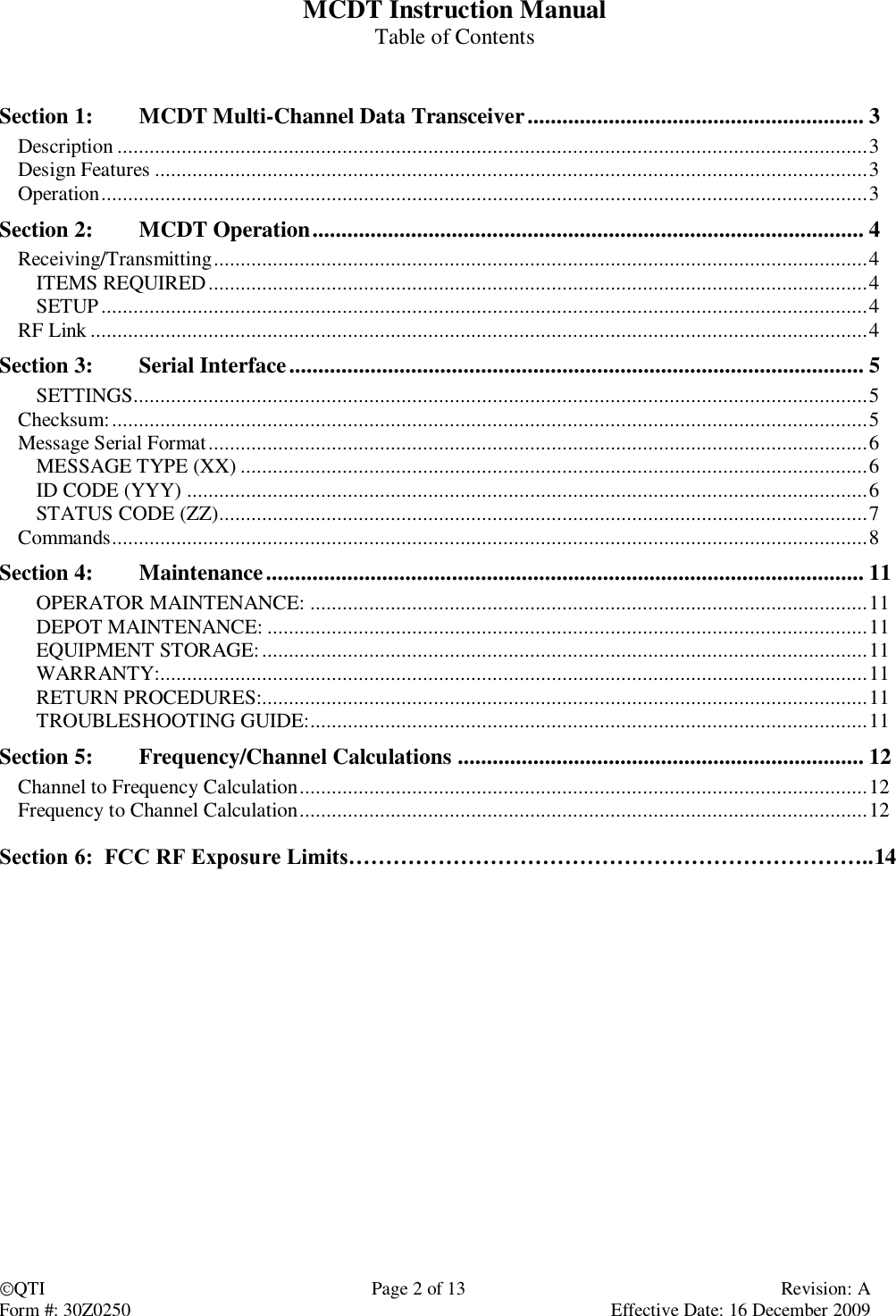
![QTI Page 3 of 13 Revision: A Form #: 30Z0250 Effective Date: 16 December 2009 Section 1: MCDT Multi-Channel Data Transceiver Description The Multi-Channel Data Transceiver (MCDT) is available as a modular modem to OEM users who want to design it into their own equipment. Equipped with RS-485 communications, the MCDT can be set up using a personal computer. The MCDT is capable of transmitting or receiving SEIWG-5 data messages, including a status code and distinct ID, over a radio frequency. This frequency is selectable via synthesizer control circuits, providing a selection of up to 1920 RF channels, depending on the model’s frequency range. The MCDT comes in Low-Band, Medium-Band, and High-Band models, having the following frequency ranges: Low Band Medium Band High Band Channel 001 = 138.025 MHz Channel 001 = 154.005 MHz Channel 001 = 162.00625 MHz Channel 600 = 153.000 MHz Channel 1600 = 162.000 MHz Channel 1920 = 174.000 MHz Antenna: MMCX plug to accept user-supplied antenna Power Supply: User-supplied, 4.8V to 16.5VDC nominal, 18 VDC absolute maximum Connections: Current Draw approximations: Mode Current Comments Sleep 33uA RS485 command will wake unit up Active 7.0mA Receiver Off / Microprocessor On Transmission(1Watt) 57ms @ 1.5A Pulse Current Provided by Super Caps Transmission(2Watt) 57ms @ 3A Pulse Current Provided by Super Caps Receiver On 12.6mA Receiver On – Waiting for valid RF message Receiver Active 16.9mA RF message received – Microprocessor On Design Features ID Code Selection 000-999 for EMIDS, 000-063 for all other formats Directional, sensor fault, low battery, tamper, and test status codes for EMIDS format Able to receive and transmit MIDS 20-bit, MMIDS / EMIDS 29-bit messages, TRSS, or REMBASS MMCX antenna port matched to 50 ohms Conformal-coated and shielded circuit assembly Operation Connections to the MCDT can be made using a ribbon cable connected to J1 or using flying leads soldered directly to the VIAS. See Connections table above to determine pin outs. Using the settings provided in Section 3: Serial Interface, open a serial communication program such as HyperTerminal and supply power to the MCDT. Upon establishing a connection to the MCDT, the computer screen will display “BL<LF><CR>” for one second and then display the version information. This indicates a ready status. The “BL” (Boot Loader) response provides for one (1) second the opportunity to enter the programming mode. Sending a “P” will enter the firmware upgrade mode and erase the firmware of the device. Therefore, the user is advised not to send any characters to the unit, especially not the character “P”, to the unit before the version information is received. Function J1 (10-pin FTS-105) Via Vin [Input] 4.8 to 16.5 VDC 1, 2 E1 GND 8, 9, 10 E8 RS485 – A+ [I/O] 5 E4 RS485 – B– [I/O] 4 E5 Transmit Drive [Output] Active low 3 E3 VCC [Out] 5.4VDC 6 E2 Wakeup [I/O] Active low 7 E6](https://usermanual.wiki/Qual-Tron/QTIMIDSMCDT/User-Guide-1263988-Page-3.png)
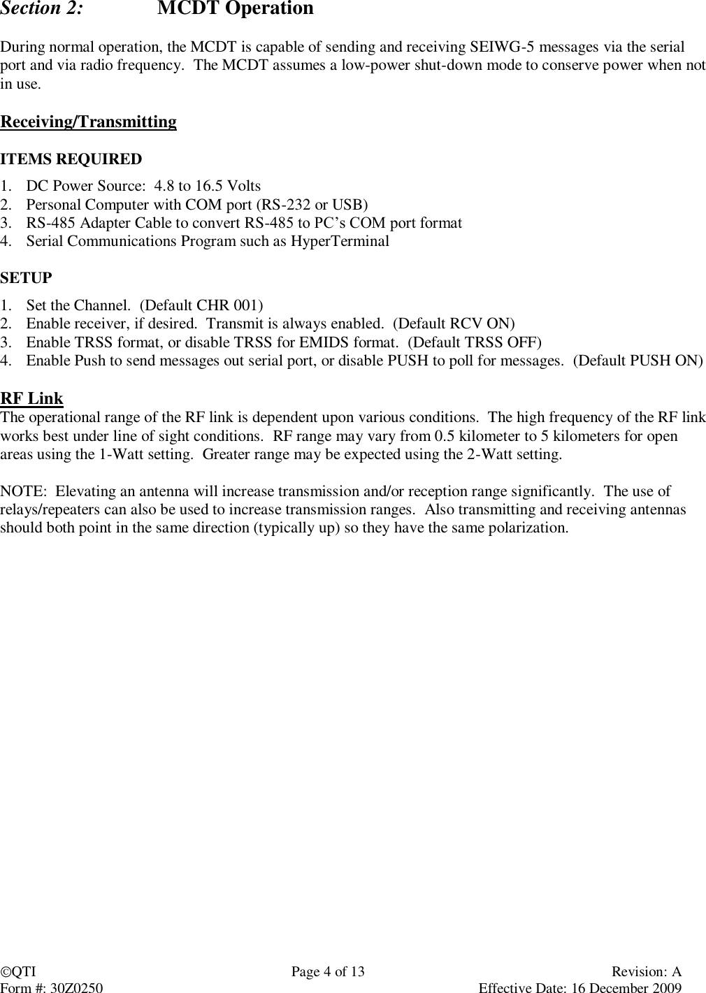
![QTI Page 5 of 13 Revision: A Form #: 30Z0250 Effective Date: 16 December 2009 Section 3: Serial Interface The MCDT defaults to a low-power shut down mode. Upon receiving an RF message, the MCDT will send the message via the serial port and then return to shut-down immediately. The user may initiate serial communication by sending the MCDT two ASCII characters. After 1 minute of inactivity on the serial port, the MCDT returns to low-power shut down mode. If the user disables the PUSH setting and the MCDT has a new message on hold in the buffer, the shut-down mode will be prevented because this condition pulls the Wakeup [I/O] line low. The MCDT communicates over RS-485. Send a command followed by a carriage return (<CR>). Settings are retained only until power is turned off unless the SAV command is used to store them to the unit’s flash memory. When sending commands and queries, a two-digit hexadecimal checksum (cs) can be used to check data integrity. This is done by preceding the command with “#” and following the command with the checksum value and a carriage return. If a checksum is not desired, simply do not include the # or checksum (cs) value. SETTINGS 38400 baud, fixed No parity 8 bit 1 stop bit No flow control Checksum: To use checksum begin the command with “#” and end the command with the calculated checksum (cs) value followed by the carriage return <CR>. A command with an invalid checksum is ignored and no reply is sent. The checksum is a 2 digit hexadecimal calculated as the 2’s compliment of the sum of the command string. Using the checksum also allows and requires using the serial ID. The universal ID is X, so all units will acknowledge these commands. The unit will respond with its specific ID Example: Sample syntax: Action With Checksum Without Checksum Get channels: #XCHN04<CR> CHN<CR> Returns: #AChnR 2 ChnX 456B0<CR> CHNR 2 CHNX 456<CR> Set channels to 2: #XCHN 2B2<CR> CHN 2<CR> Returns: #ACHNR 2 CHNX 21D<CR> CHNR 2 CHNX 2<CR> Note: “A” is just a sample serial ID, and may be different. Example checksum calculator char CRC2sComp( char *buffr, int end) {//creates 2's complement int c; int calcSum = 0; for( c = 0; c <= end; c ++ ) calcSum += buffr[c]; calcSum ^= 0xFF; //1's complement calcSum += 1; //now 2's complement return (char)(calcSum); }](https://usermanual.wiki/Qual-Tron/QTIMIDSMCDT/User-Guide-1263988-Page-5.png)