Qual Tron QTIMIDSMCDT 138-153 MHZ DATA RADIO User Manual MIDS Manual
Qual-Tron, Inc. 138-153 MHZ DATA RADIO MIDS Manual
Instruction Manual

QTI Revision: B
Form #: 30Z0250 Effective Date: 08 April 2010
9409 E. 55th Pl. S. * Tulsa, OK 74145 * (918) 622-7052 * Fax (918) 664-8557
M
MC
CD
DT
T
I
IN
NS
ST
TR
RU
UC
CT
TI
IO
ON
N
M
MA
AN
NU
UA
AL
L
MCDT Multi-Channel Data Transceiver
P/N 10D1037
All rights reserved. No part of this book may be reproduced or utilized in any form or by any means, electronic or
mechanical, without the prior written permission of Qual-Tron, Inc.

QTI Page 2 of 13 Revision: A
Form #: 30Z0250 Effective Date: 16 December 2009
MCDT Instruction Manual
Table of Contents
Section 1: MCDT Multi-Channel Data Transceiver .......................................................... 3
Description ............................................................................................................................................ 3
Design Features ..................................................................................................................................... 3
Operation ............................................................................................................................................... 3
Section 2: MCDT Operation ............................................................................................... 4
Receiving/Transmitting .......................................................................................................................... 4
ITEMS REQUIRED ........................................................................................................................... 4
SETUP ............................................................................................................................................... 4
RF Link ................................................................................................................................................. 4
Section 3: Serial Interface ................................................................................................... 5
SETTINGS ......................................................................................................................................... 5
Checksum: ............................................................................................................................................. 5
Message Serial Format ........................................................................................................................... 6
MESSAGE TYPE (XX) ..................................................................................................................... 6
ID CODE (YYY) ............................................................................................................................... 6
STATUS CODE (ZZ) ......................................................................................................................... 7
Commands ............................................................................................................................................. 8
Section 4: Maintenance ....................................................................................................... 11
OPERATOR MAINTENANCE: ........................................................................................................ 11
DEPOT MAINTENANCE: ................................................................................................................ 11
EQUIPMENT STORAGE: ................................................................................................................. 11
WARRANTY:.................................................................................................................................... 11
RETURN PROCEDURES:................................................................................................................. 11
TROUBLESHOOTING GUIDE: ........................................................................................................ 11
Section 5: Frequency/Channel Calculations ...................................................................... 12
Channel to Frequency Calculation .......................................................................................................... 12
Frequency to Channel Calculation .......................................................................................................... 12
Section 6: FCC RF Exposure Limits……………………………………………………………..14
QTI Page 3 of 13 Revision: A
Form #: 30Z0250 Effective Date: 16 December 2009
Section 1: MCDT Multi-Channel Data Transceiver
Description
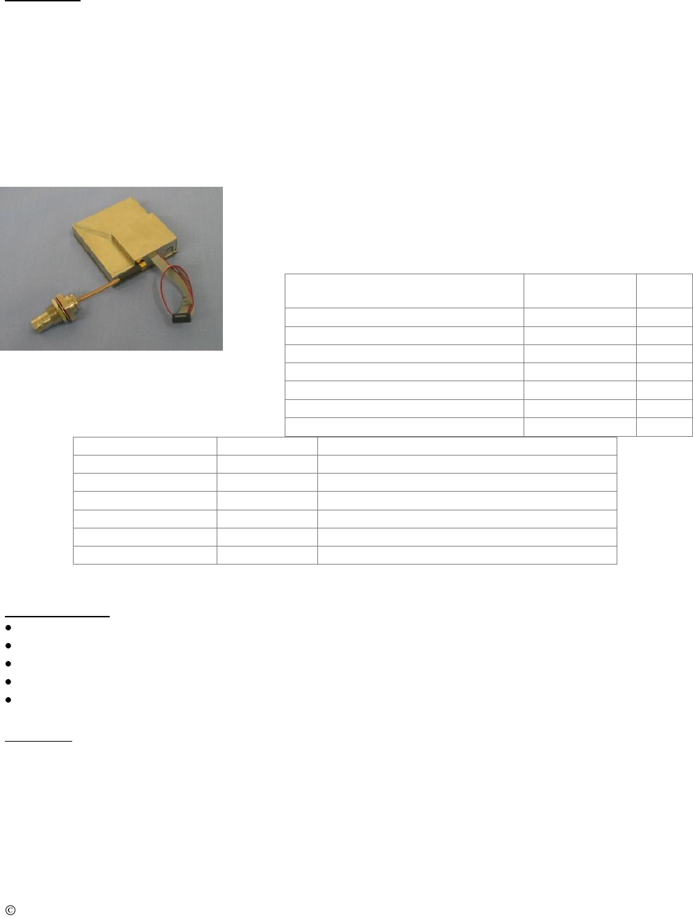
The Multi-Channel Data Transceiver (MCDT) is available as a modular modem to OEM users who want to
design it into their own equipment. Equipped with RS-485 communications, the MCDT can be set up using a
personal computer. The MCDT is capable of transmitting or receiving SEIWG-5 data messages, including a
status code and distinct ID, over a radio frequency. This frequency is selectable via synthesizer control
circuits, providing a selection of up to 1920 RF channels, depending on the model’s frequency range. The
MCDT comes in Low-Band, Medium-Band, and High-Band models, having the following frequency ranges:
Low Band
Medium Band
High Band
Channel 001 = 138.025 MHz
Channel 001 = 154.005 MHz
Channel 001 = 162.00625 MHz
Channel 600 = 153.000 MHz
Channel 1600 = 162.000 MHz
Channel 1920 = 174.000 MHz
Antenna: MMCX plug to accept user-supplied antenna
Power Supply: User-supplied, 4.8V to 16.5VDC nominal,
18 VDC absolute maximum
Connections:
Current Draw approximations:
Mode
Current
Comments
Sleep
33uA
RS485 command will wake unit up
Active
7.0mA
Receiver Off / Microprocessor On
Transmission(1Watt)
57ms @ 1.5A
Pulse Current Provided by Super Caps
Transmission(2Watt)
57ms @ 3A
Pulse Current Provided by Super Caps
Receiver On
12.6mA
Receiver On – Waiting for valid RF message
Receiver Active
16.9mA
RF message received – Microprocessor On
Design Features
ID Code Selection 000-999 for EMIDS, 000-063 for all other formats
Directional, sensor fault, low battery, tamper, and test status codes for EMIDS format
Able to receive and transmit MIDS 20-bit, MMIDS / EMIDS 29-bit messages, TRSS, or REMBASS
MMCX antenna port matched to 50 ohms
Conformal-coated and shielded circuit assembly
Operation
Connections to the MCDT can be made using a ribbon cable connected to J1 or using flying leads soldered
directly to the VIAS. See Connections table above to determine pin outs. Using the settings provided in Section
3: Serial Interface, open a serial communication program such as HyperTerminal and supply power to the
MCDT. Upon establishing a connection to the MCDT, the computer screen will display “BL<LF><CR>” for
one second and then display the version information. This indicates a ready status.
The “BL” (Boot Loader) response provides for one (1) second the opportunity to enter the programming mode.
Sending a “P” will enter the firmware upgrade mode and erase the firmware of the device. Therefore, the user
is advised not to send any characters to the unit, especially not the character “P”, to the unit before the version
information is received.
Function
J1
(10-pin FTS-105)
Via
Vin [Input] 4.8 to 16.5 VDC
1, 2
E1
GND
8, 9, 10
E8
RS485 – A+ [I/O]
5
E4
RS485 – B– [I/O]
4
E5
Transmit Drive [Output] Active low
3
E3
VCC [Out] 5.4VDC
6
E2
Wakeup [I/O] Active low
7
E6

QTI Page 4 of 13 Revision: A
Form #: 30Z0250 Effective Date: 16 December 2009
Section 2: MCDT Operation
During normal operation, the MCDT is capable of sending and receiving SEIWG-5 messages via the serial
port and via radio frequency. The MCDT assumes a low-power shut-down mode to conserve power when not
in use.
Receiving/Transmitting
ITEMS REQUIRED
1. DC Power Source: 4.8 to 16.5 Volts
2. Personal Computer with COM port (RS-232 or USB)
3. RS-485 Adapter Cable to convert RS-485 to PC’s COM port format
4. Serial Communications Program such as HyperTerminal
SETUP
1. Set the Channel. (Default CHR 001)
2. Enable receiver, if desired. Transmit is always enabled. (Default RCV ON)
3. Enable TRSS format, or disable TRSS for EMIDS format. (Default TRSS OFF)
4. Enable Push to send messages out serial port, or disable PUSH to poll for messages. (Default PUSH ON)
RF Link
The operational range of the RF link is dependent upon various conditions. The high frequency of the RF link
works best under line of sight conditions. RF range may vary from 0.5 kilometer to 5 kilometers for open
areas using the 1-Watt setting. Greater range may be expected using the 2-Watt setting.
NOTE: Elevating an antenna will increase transmission and/or reception range significantly. The use of
relays/repeaters can also be used to increase transmission ranges. Also transmitting and receiving antennas
should both point in the same direction (typically up) so they have the same polarization.

QTI Page 5 of 13 Revision: A
Form #: 30Z0250 Effective Date: 16 December 2009
Section 3: Serial Interface
The MCDT defaults to a low-power shut down mode. Upon receiving an RF message, the MCDT will send
the message via the serial port and then return to shut-down immediately. The user may initiate serial
communication by sending the MCDT two ASCII characters. After 1 minute of inactivity on the serial port,
the MCDT returns to low-power shut down mode. If the user disables the PUSH setting and the MCDT has a
new message on hold in the buffer, the shut-down mode will be prevented because this condition pulls the
Wakeup [I/O] line low.
The MCDT communicates over RS-485. Send a command followed by a carriage return (<CR>). Settings are
retained only until power is turned off unless the SAV command is used to store them to the unit’s flash
memory. When sending commands and queries, a two-digit hexadecimal checksum (cs) can be used to check
data integrity. This is done by preceding the command with “#” and following the command with the
checksum value and a carriage return. If a checksum is not desired, simply do not include the # or checksum
(cs) value.
SETTINGS
38400 baud, fixed
No parity
8 bit
1 stop bit
No flow control
Checksum:
To use checksum begin the command with “#” and end the command with the calculated checksum (cs) value
followed by the carriage return <CR>. A command with an invalid checksum is ignored and no reply is sent.
The checksum is a 2 digit hexadecimal calculated as the 2’s compliment of the sum of the command string.
Using the checksum also allows and requires using the serial ID. The universal ID is X, so all units will
acknowledge these commands. The unit will respond with its specific ID
Example: Sample syntax:
Action
With Checksum
Without Checksum
Get channels:
#XCHN04<CR>
CHN<CR>
Returns:
#AChnR 2 ChnX 456B0<CR>
CHNR 2 CHNX 456<CR>
Set channels to 2:
#XCHN 2B2<CR>
CHN 2<CR>
Returns:
#ACHNR 2 CHNX 21D<CR>
CHNR 2 CHNX 2<CR>
Note: “A” is just a sample serial ID, and may be different.
Example checksum calculator
char CRC2sComp( char *buffr, int end)
{//creates 2's complement
int c;
int calcSum = 0;
for( c = 0; c <= end; c ++ )
calcSum += buffr[c];
calcSum ^= 0xFF; //1's complement
calcSum += 1; //now 2's complement
return (char)(calcSum);
}

QTI Page 6 of 13 Revision: A
Form #: 30Z0250 Effective Date: 16 December 2009
Message Serial Format
Decoded message is sent via RS-485:
RXM XX YYY ZZ<CR>, where XX = Message Type, YYY = ID code, and ZZ = status code; all values are
hexadecimal.
MESSAGE TYPE (XX)
The message type consists of two (2) hexadecimal characters. The first character shows the parity; the most
significant bit will be set if the parity is bad. The second character identifies the type.
Examples of parity:
Good parity 0X (0000xxxx in binary)
Bad parity 8X (1000xxxx in binary)
List of types:
MIDS X7
EMIDS/TRSS XD (EMIDS format if TRSS mode OFF (default) / TRSS format if TRSS ON)
REMBASS X6
NOTE: Because EMIDS and TRSS have the same message type, the message format is distinguished based on
whether TRSS mode is enabled (TRSS format) or disabled (EMIDS format).
The MCDT can receive MIDS and REMBASS messages at any time without setting the unit to a particular
mode. In addition, the unit can receive either EMIDS or TRSS messages, but the user must specify which for
the MCDT to expect since these two have the same message type.
ID CODE (YYY)
The unit ID code consists of three (3) hexadecimal characters, but only EMIDS messages use all three. MIDS,
TRSS and REMBASS are limited to ID codes 000-03F (63). EMIDS uses 000-3E7 (999).

QTI Page 7 of 13 Revision: A
Form #: 30Z0250 Effective Date: 16 December 2009
STATUS CODE (ZZ)
Status Codes depend upon the message format. MIDS has no status code, and these characters should always
be 00. EMIDS status codes are listed in the following table:
STATUS
CODE
ALARM
TAMP/TEST
LOBATT
R>L
L>R
MEANING
00
0
0
0
0
0
RESERVED
01
0
0
0
0
1
RESERVED
02
0
0
0
1
0
RESERVED
03
0
0
0
1
1
FAULT
04
0
0
1
0
0
RESERVED
05
0
0
1
0
1
RESERVED
06
0
0
1
1
0
RESERVED
07
0
0
1
1
1
FAULT, LOBATT
08
0
1
0
0
0
TEST
09
0
1
0
0
1
RESERVED
0A
0
1
0
1
0
RESERVED
0B
0
1
0
1
1
TEST, FAULT
0C
0
1
1
0
0
TEST, LOBATT
0D
0
1
1
0
1
RESERVED
0E
0
1
1
1
0
RESERVED
0F
0
1
1
1
1
TEST, FAULT, LOBATT
10
1
0
0
0
0
ALARM
11
1
0
0
0
1
ALARM, L>R
12
1
0
0
1
0
ALARM, R>L
13
1
0
0
1
1
ALARM, FAULT
14
1
0
1
0
0
ALARM, LOBATT
15
1
0
1
0
1
ALARM, L>R, LOBATT
16
1
0
1
1
0
ALARM, R>L, LOBATT
17
1
0
1
1
1
ALARM, FAULT,
LOBATT
18
1
1
0
0
0
TAMP
19
1
1
0
0
1
RESERVED
1A
1
1
0
1
0
RESERVED
1B
1
1
0
1
1
TAMP, FAULT
1C
1
1
1
0
0
TAMP, LOBATT
1D
1
1
1
0
1
RESERVED
1E
1
1
1
1
0
RESERVED
1F
1
1
1
1
1
TAMP, FAULT, LOBATT
Status Code Table

QTI Page 8 of 13 Revision: A
Form #: 30Z0250 Effective Date: 16 December 2009
Commands
?…….. Brings up the help menu
The current help menu (without checksums) appears as follows:
Commands
---------
HELP/?:
Show this menu
CHR:
Get/Set rcv Chan
CHX:
Get/Set xmit Chan
MSG:
Get rcvd msg
PWR:
Get/Set xmt pwr level
PSH:
Get/Set push mode
RCV:
Get/Set receive mode
RSS:
Get receive signal strength
RST:
Reset
SAV:
Save Current Parameters
SLP:
Sleep
SRN:
Get unit serial num
TMP:
Read Temp
TRS:
Turn TRSS Format On/Off
TXM:
Xmit msg, type, ID, stat
VER:
Show versions
CHR…Get/Set the receive channel. (Follow with SAV command.)
Low Band: 0-600
Med Band: 0-1600
High Band: 0-1920
Get the channel:
CHR<CR>
Returns:
CHR Z<CR>
Set the channel:
CHR Z<CR>
Returns:
CHR Z SET<CR>
Or CHR Z ERR<CR> if invalid value given
CHX…Get/Set the transmit channel. (Follow with SAV command.)
Low Band: 0-600
Med Band: 0-1600
High Band: 0-1920
Get the channel:
CHX<CR>
Returns:
CHX Z<CR>
Set the channel:
CHX Z<CR>
Returns:
CHX Z SET<CR>
Or CHX Z ERR<CR> if invalid value given
MSG….. Recall a previous message.
0-9 with 0 being most recent message, and 9 being the oldest message
Get a message:
MSG X<CR>
Returns:
RXM TT III SS<CR>, where TT is the message type,III is the ID, and
SS is the status code
NEW…..Read New messages. Use when PUSH is OFF. (This command is not listed under Help menu.)

QTI Page 9 of 13 Revision: A
Form #: 30Z0250 Effective Date: 16 December 2009
Poll for a new message:
NEW<CR>
Returns:
RXM TT III SS<CR>, where TT is the message type,III
is the ID, and SS is the status code
Returns if no new message:
RXM<CR>
PSH….Get/Set to push new messages out the serial port.
1 = ON (New messages pushed out the serial port when received)
0 = OFF (must poll for new messages)
Get PUSH mode:
PSH<CR>
Returns:
PSH Z<CR>
Set PUSH mode:
PSH Z<CR>
Returns:
PSH Z<CR>
PWR…Get/Set the transmitter power level.
1 = 1 watt transmit power at least
2 = 2 watt transmit power at least
Get power level:
PWR<CR>
Returns:
PWR Z<CR>
Set power level:
PWR Z<CR>
Returns:
PWR Z<CR>
RCV ….. Get/Set receive mode.
1 = ON (receiver enabled)
0 = OFF (receiver disabled)
Get receive mode:
RCV<CR>
Returns:
RCV Z<CR>
Set receive mode:
RCV Z<CR>
Returns:
RCV Z<CR>
RSS….. Get the receive signal strength.
Returns a value from 0- 10230
Get RSSI:
RSS<CR>
Returns:
RSS Z<CR>
Conversion
dBm = 0.0106 * Z – 150dBm
RST…… Reset the unit. No return string.
Reset the unit:
RST<CR>
Returns:
SAV …... Save the current parameters in flash memory. Use this to store any parameter changes.
Save current settings:
SAV<CR>
Returns:
SAV MCDT DATA<CR>
SLP……. Shut down the serial port immediately to conserve power.
Enter low power mode:
SLP<CR>
Returns:
SLP<CR>
SRN…. Get the unit serial number.
The serial number is a string up to 20 characters long.
dBm
RSS value
-91
5284
-101
4523
-111
3570
-121
2591

QTI Page 10 of 13 Revision: A
Form #: 30Z0250 Effective Date: 16 December 2009
Get serial number:
SRN<CR>
Returns:
SRN Z<CR>
TEMP… Get the board temperature in degrees Celsius, with a tenth degree precision.
Get temperature:
TMP<CR>
Returns:
TMP Z.Z<CR>
TRS…..Get/Set TRSS message format.
1 = ON (TRSS message format enabled, EMIDS disabled)
0 = OFF (TRSS message format disabled, EMIDS enabled)
Get TRSS format:
TRS<CR>
Returns:
TRS Z<CR>
Set TRSS format:
TRS 1<CR>
Returns:
TRS 1<CR>
Set EMID format:
TRS 0<CR>
Returns:
TRS 0<CR>
TXM…... Transmit Message; explained in Transmitting section below.
Send RF message:
TXM TT III SS<CR>, where TT is the message type,
III is the ID, and SS is the status code
Returns:
TXM XX YYY ZZ<CR>
VER…... Get the firmware version.
Get version:
VER<CR>
Returns:
MCDT VV.VVV B<CR>, where MCDT is the model
VV.VVV is the version, and B is the frequency band

QTI Page 11 of 13 Revision: A
Form #: 30Z0250 Effective Date: 16 December 2009
Section 4: Maintenance
OPERATOR MAINTENANCE:
The MCDT has been designed as low cost low maintenance equipment. All components are conformal coated
which reduces the amount of maintenance required. The only required operator maintenance is to inspect the
equipment for damage and keep the equipment clean of dirt, grime, and caked on mud.
NOTE: Do not submerge the equipment in water. This could result in damage.
DEPOT MAINTENANCE:
Upper echelon maintenance will be performed by the supplier of the equipment. If the equipment is beyond the
user capability to repair, it can be returned to the supplier for test and evaluation. Upon completion of the
inspection, the supplier will notify the user if the unit can be repaired. If the equipment is not covered by the
warranty, an estimate will be provided for repair costs. If the equipment is not repairable, the supplier will specify
replacement costs. (Note: See warranty below for return procedures.)
EQUIPMENT STORAGE:
Upon return to the facility, clean equipment as noted in operator maintenance above. Remove batteries from all
equipment to prevent possible damage. If batteries are left in the equipment, transmitters will continue to send fault
alarms every 10 minutes causing a continuous drain on the batteries and possibly resulting in damaged or ruptured
batteries. After cleaning, return the equipment to the storage cases. Store in a dry, room temperature environment.
WARRANTY:
Qual-Tron, Inc. guarantees all products to be free from defects in materials and workmanship for 12 months from
the date of purchase. Damage due to misuse, accidents, lightning strikes, unauthorized service, environmental
conditions beyond the equipment specifications, acts of war or damage other than fair, wear and tear is excluded
from this warranty.
RETURN PROCEDURES:
For support and service, please contact the following. To return any material, contact Qual-Tron, Inc. to receive a
Return Material Authorization (RMA) number. Once an RMA number has been assigned, ship the material to the
address below and reference the RMA number on the packing slip. Qual-Tron will return the equipment as quickly
as possible to the user.
QUAL-TRON, INC.
Attn: Sales Ph: 918-622-7052
9409 E. 55th Place Fax: 918-664-8557
Tulsa, OK 74145 email: sales@qual-tron.com
TROUBLESHOOTING GUIDE:
Defect
Possible Cause
Corrective Action
Stage
Area
Empl
Site
Will not turn on
Battery low voltage
Check power supply
X
Does not
receive/transmit
alarms
Battery low voltage
Check power supply
X
Transmitter & receiver too
close to each other
Experiment with antenna combinations
(with & without)
X
X
Frequency
Verify transmitter and receiver are on
the same frequency
X
Receiver not enabled
Verify receive mode is on
X
Wrong message format
Check TRSS mode
X

QTI Page 12 of 13 Revision: A
Form #: 30Z0250 Effective Date: 16 December 2009
Section 5: Frequency/Channel Calculations
Frequency Ranges
Frequency
Range
Frequency
Channel
Steps
Max
Channels
Min
Max
Low
138 MHz
154 MHz
25 kHz
600
Mid
154 MHz
162 MHz
5 kHz
1600
High
162 MHz
174 MHz
6.25 kHz
1920
Channel to Frequency Calculation
Channel * Channel Step + Min Frequency = Frequency for Channel
Examples:
- Low Band Channel 20
- 20 * 0.025 +138 =138.5 MHz
- Mid Band Channel 300
- 300 * 0.005 + 154 = 155.5 MHz
Frequency to Channel Calculation
(Frequency – Min Frequency) / Channel Step = Channel for Frequency
Examples:
- Low Band 151.5 MHz
- (151.5 – 138) / 0.025 = Channel 540
- High Band 172.5 MHz
- (172.5 – 162) / 0.00625 = Channel 1680

QTI Page 13 of 13 Revision: A
Form #: 30Z0250 Effective Date: 16 December 2009
Section 6: FCC RF Exposure Limits:
This device complies with the MPE requirements by providing a safe separation distance of 30 cm
between the antenna, including any radiating structure, and any persons when normally operated.
CAUTION:
The antenna(s) used for this transmitter must not be co-located or operating in conjunction with
any other antenna or transmitter. This device is approved with emissions having a source-based time-
averaging duty factor not exceeding 50%.
Operating at a lower duty cycle than 50% will allow proportionately shorter exposure distance
than 30 cm.