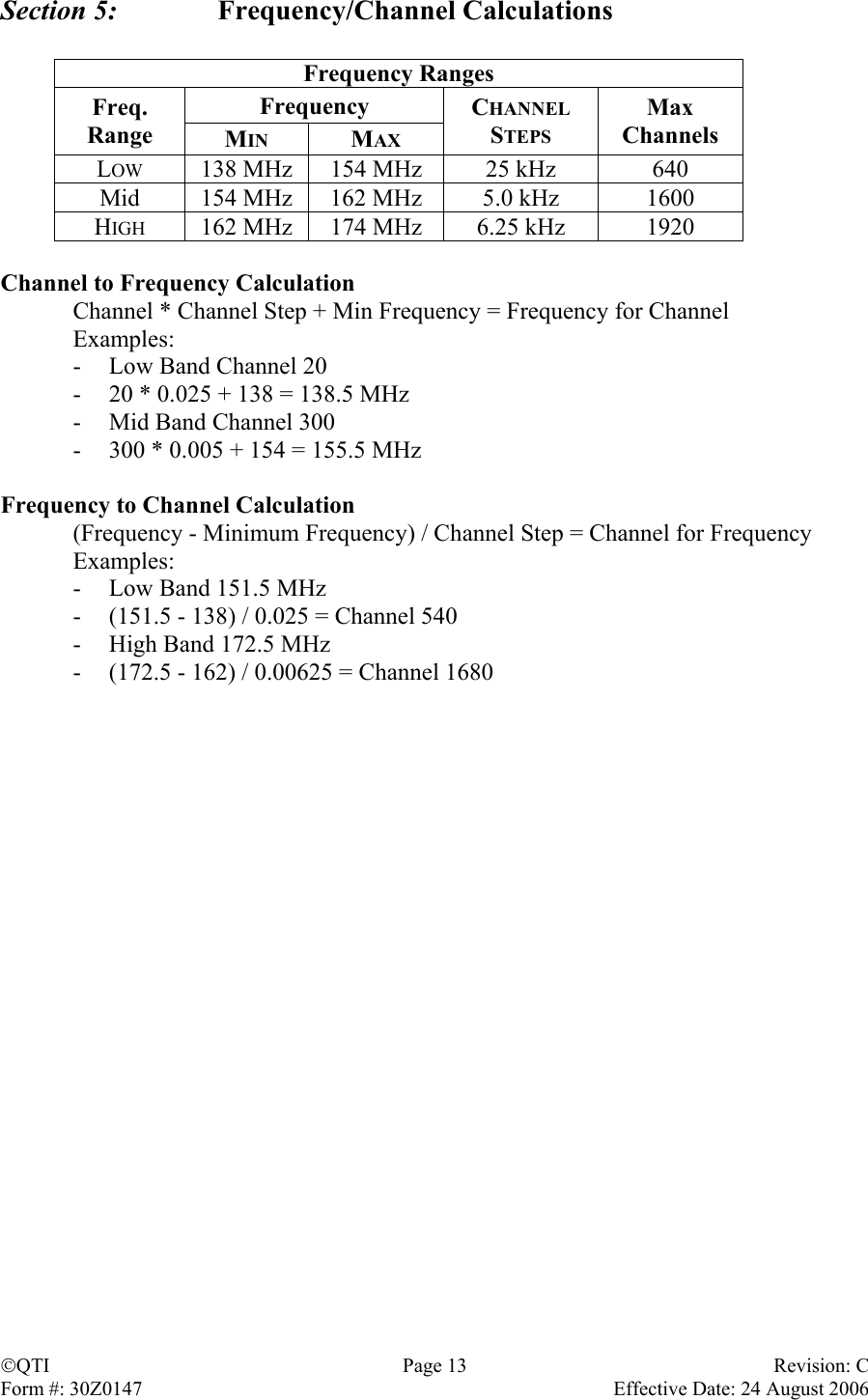
Qual Tron QTIMIDSMXMT MXMT – MIDS Single Channel Fixed Frequency Relay User Manual MIDS Manual

Qual-Tron, Inc. MXMT – MIDS Single Channel Fixed Frequency Relay MIDS Manual

Manual

  9409 E. 55th Pl. S. *  Tulsa, OK  74145  *  (918) 622-7052  *  Fax (918) 664-8557   MMIIDDSS  IINNSSTTRRUUCCTTIIOONN  MMAANNUUAALL    Receivers MPDM-MIDS Hand Held Receiver  (P/N 13D0109-1) and MRCR-MIDS Remote  Control Receiver (P/N 13D0148)Transmitters MRCT-MIDS Remote Control Transmitter (P/N 13D0160, 13D0812) and MXMT-MIDS Transmitter (P/N 13D0159)  All rights reserved.  No part of this book may be reproduced or utilized in any form or by any means, electronic or mechanical, without the prior written permission of Qual-Tron, Inc.   QTI     Revision: C Form #: 30Z0147    Effective Date: 24 August 2006
MIDS Manual Table of Contents  Section 1:    MIDS Transmitter (MXMT) Description …………………………………………………………………………………… Page 3 Features …………………………………………………………………………………… Page 3 Operation …………………………………………………………………………………… Page 4 RF Link  ……………………………………………………………………………………  Page 5 Emplacement Considerations  …………………………………………………………………  Page 5  Section 2:    MIDS Remote Control Transmitter (MRCT) Description …………………………………………………………………………………… Page 6 Features …………………………………………………………………………………… Page 6 Operation …………………………………………………………………………………… Page 7 RF Link  ……………………………………………………………………………………  Page 8 Emplacement Considerations  …………………………………………………………………  Page 8  Section 3:    MIDS Hand Held Receiver (MPDM) Description …………………………………………………………………………………… Page 9 Features …………………………………………………………………………………… Page 9 Operation …………………………………………………………………………………… Page 10 RF Link  ……………………………………………………………………………………  Page 10  Section 4:    MID Remote Control Receiver (MRCR) Description …………………………………………………………………………………… Page 11 Features …………………………………………………………………………………… Page 11 Operation …………………………………………………………………………………… Page 12 RF Link  ……………………………………………………………………………………  Page 12  Section 5:   Frequency/Channel Calculations Channel to Frequency  …………………………………………………………………………  Page 13 Frequency to Channel  …………………………………………………………………………  Page 13   Section 6:    FCC Notice / RF FCC Notice  …………………………………………………………………  Page 14 FCC Compliance Information RF Exposure – MPE/SAR ………………………………………………………………… ………………………………………………………………… Page 14 Page 14                  QTI Page 2 Revision: C Form #: 30Z0147    Effective Date: 24 August 2006
Section 1:  MIDS Transmitter (MXMT)   Description The MIDS Transmitter (MXMT) is used to transmit a digitally encoded ID number, via narrow band VHF (138-174 MHz) RF frequencies, when activated by various types of attached ground sensors.  The transmitter is factory pre-set to a single (customer specified) channel.  See frequency range below.  Channel:  Factory Pre-Set Single Channel Sensor Connector Battery CapAntenna  ID Codes:  00-63 (Even numbers only for   normal use, all numbers for  special applications.)  Antenna:  Wire Whip, ¼ Wave  Frequency Range: 138-174 MHz  Power Supply:  1-2 each 9 V DC Batteries  (MN1604)  Battery Life:  4-6 months in temperate climate  Sensor:  Any Qual-Tron sensor  Pin Connections:  A: Ground   B: +9 VDC   C: Tx Trigger   D: ID Code Control (do not use)  Design Features •  ID code selection (Switches inside battery compartment) •  Internal power ON – Normal operation – Antenna up •  Internal power OFF – Non operating – Battery cap down •  Internal power ON – Sensor alignment – Battery cap up •  Transmit ID code alarms •  Sensor Fault alarms •  Sealed battery compartment •  Four pin Mil-Type (sensor) connector •  Potted and sealed electronic components •  Injection molded lexan plastic housing •  Metal battery cap clamps with heat welded screw inserts •  Frequency matched antenna  QTI Page 3 Revision: C Form #: 30Z0147    Effective Date: 24 August 2006
Operation ID Code Set-Up – The ID is the number transmitted when the attached sensor is activated. The ID number transmitted is the sum of the switches, 8A + B.  These switches should be set with the screwdriver provided to prevent damage to the plastic slots.  Use only even number ID codes between 00-62.  Example:  ID Code 30   (A) x8 position = 3; (B) x1 position = 6;       = (8 x 3) + (1 x 6)       =     24    +    6  =  30  (ID number 30 will be transmitted)  ID Switch Setting Chart ID X8 x1 ID x8 x1 ID x8 x1 ID x8 x1 00  0  0  16  2  0  32  4  0  48  6  0 02 0  2 18 2  2 34 4  2 50 6  2 04  0  4  20  2  4  36  4  4  52  6  4 06 0  6 22 2  6 38 4  6 54 6  6 08  1  0  24  3  0  40  5  0  56  7  0 10 1  2 26 3  2 42 5  2 58 7  2 12  1  4  28  3  4  44  5  4  60  7  4 14 1  6 30 3  6 46 5  6 62 7  6  Note:  For all applications use even ID codes only.  When a sensor fault occurs (if the   connection between the transmitter and sensor is broken for any reason), the   transmitter will activate and transmit the next higher odd ID number.   Example:  If the normal ID code is 20, then 21 would be transmitted when   a sensor fault occurs.  This would advise the user of a special problem,   which needs immediate attention. QTI Page 4 Revision: C Form #: 30Z0147    Effective Date: 24 August 2006
The MXMT has four modes of operation.  These modes are controlled by internal tilt switches. Normal Operation – The MXMT may be put in normal mode by placing it with the antenna up.  While in normal mode the MXMT is triggered by an externally connected sensor.  Sensor Alignment – The MXMT may be put in alignment mode by placing it with the battery cap up.  The alignment mode is used with the infrared sensors (Break beam and Passive IR).  When the sensors are aligned, the LED on the sensor will illuminate when a target is detected.  (Note: LED will not illuminate in normal operation mode.) Open/Input – The MXMT may be put in open/input by placing it with the antenna up and disconnecting the sensor. An alarm is sent when a sensor is disconnected, sensor cable is cut, or the sensor is out of alignment.  The ID code transmitted is the next higher odd ID code. This ID code message will repeat every 10 minutes until the condition is corrected. Power Off – Power is turned off by placing the unit with the battery cap down.  This mode is used to transport the transmitter to the deployment location with no transmission.  Sensor Connection The MXMT can be used with all Qual-Tron sensors.  Simply attach any sensor using the mil-type connector (align-twist-lock) to the connector on the MXMT.  Set up the sensor according to its instruction manual.  Sensors that are compatible with the MXMT: •  Break Wire •  Magnetic •  Active IR Break Beam •  Passive IR •  Passive IR Long Range •  Seismic •  Day/Night •  Sensor Timed Relay •  Others for Special Application  RF Link The operational range of the RF link is dependent upon various conditions.  The high frequency of the RF link works best under line of sight conditions.  Transmission can range from a few hundred yards to several miles, depending on terrain. Non line-of-sight can play a part in decreasing the transmission range.  The transmission range can be extended with the use of relays, or by elevating the antenna at either the transmitter or receiver position.  Emplacement Considerations The MXMT can be buried under one inch of compacted soil.  Use caution not to bend the antenna when burying. QTI Page 5 Revision: C Form #: 30Z0147    Effective Date: 24 August 2006
Section 2:    MIDS Remote Control Transmitter (MRCT)   Description The MIDS Remote Control Transmitter is used as a training and test unit.  The MRCT has changeable ID code switches mounted on the side of the receiver.  The MRCT can be set to ID codes 00-63.  The switches are set to the desired ID code, and the transmit-button is pressed.  The hand held receiver receives the ID code that was set on the MRCT.  A special operation format is available for control of cameras, lights, gates, and other devices to be activated.  Channel:  Factory Pre-Set Single  Channel  ID Codes:  00-63  Antenna:  ¼ wave stub or ½ wave Rod   Frequency Range: 138-174 MHz  Power Supply:  2 each 9 V DC Batteries  (MN1604)  Battery Life:  4-6 months in temperate  climate   Antenna Connector Transmit Button ID Code Switches Battery CapDesign Features •  Easy to set ID code •  Command turn on for remote location items •  Training system for operators and deployed operations •  Allows for quick test of receivers and relays •  Sealed battery compartment •  Potted and sealed electronic components •  Injection molded lexan plastic housing •  Metal battery cap clamps with heat welded screw inserts •  Frequency matched antenna  QTI Page 6 Revision: C Form #: 30Z0147    Effective Date: 24 August 2006
Operation  MODELS MRCT-2 or Later Models ID Code Set-Up – The ID code is the number transmitted, once each time, when the MRCT transmit button is depressed.  The ID code is set using the switches located on the side of the transmitter.  The numbers can be changed by pressing either the ‘+’ button below or ‘-’ button above the displayed number.  The number displayed in the switch window will be the ID code transmitted.   Example:  ID Code 34  1st switch  = 3;   2nd switch = 4;   ID number 34 would be transmitted and displayed     on the MIDS Receiver/Monitor   NOTE: When switch ID’s 64-99 are transmitted they will  result in a received ID code of 63.    Transmit ButtonMODELS MRCT & MRCT-1 ID Code Set-Up – The ID code is the number transmitted, once each time, when the MRCT transmit button is depressed.  The ID code transmitted must be determined based on the table below.  The ID code is set using the switches located on the side of the transmitter.  These switches are set by pressing either the ‘+’ button below or ‘-’ button above the displayed number.  Example:  ID Code 28   x8 switch  = 3;   x1 switch = 4;     = (8 x 3) + (1 x 4)     =     24    +     4  = 28   ID number 28 would be transmitted and displayed x1 switchx8 switch    on the MIDS Receiver/Monitor    Transmit ButtonQTI Page 7 Revision: C Form #: 30Z0147    Effective Date: 24 August 2006
 ID Switch Setting Chart ID  x8 x1 ID  x8 x1 ID  x8 x1 ID  x8 x1 00  0 or 8  0 or 8  16  2  0 or 832  4  0 or 848  6  0 or 801  0 or 8 1 or 9  17  2 1 or 933  4 1 or 949  6 1 or 902  0 or 8  2  18  2  2  34  4  2  50  6  2 03  0 or 8 3  19  2 3 35  4 3 51  6 3 04  0 or 8  4  20  2  4  36  4  4  52  6  4 05  0 or 8 5  21  2 5 37  4 5 53  6 5 06  0 or 8  6  22  2  6  38  4  6  54  6  6 07  0 or 8 7  23  2 7 39  4 7 55  6 7 08  1 or 9  0 or 8  24  3  0 or 840  5  0 or 856  7  0 or 809  1 or 9 1 or 9  25  3 1 or 941  5 1 or 957  7 1 or 910  1 or 9  2  26  3  2  42  5  2  58  7  2 11  1 or 9 3  27  3 3 43  5 3 59  7 3 12  1 or 9  4  28  3  4  44  5  4  60  7  4 13  1 or 9 5  29  3 5 45  5 5 61  7 5 14  1 or 9  6  30  3  6  46  5  6  62  7  6 15  1 or 9 7  31  3 7 47  5 7 63  7 7  The MRCT selector switches use octal numbering system.  1-7 are their shown value.  The number ‘8’ has a value of ‘0’ and the number ‘9’ has a value of ‘1’.  RF Link The operational range of the RF link is dependent upon various conditions.  The high frequency of the RF link works best under line of sight conditions.  Transmission can range from hundreds of yards to several miles, depending on terrain.  The transmission range can be extended with the use of relays, or by elevating the antenna at either the transmitter or receiver position.  Emplacement Considerations The MRCT is a hand held unit only. QTI Page 8 Revision: C Form #: 30Z0147    Effective Date: 24 August 2006
Section 3:    MIDS Hand Held Receiver (MPDM)   Description The Mini Portable Display Monitor (MPDM) is used to receive and display the ID code number transmitted by an activated transmitter.  Only one of 64 IDs can be displayed at a time.  When a sensor is activated, its ID replaces that of the previous ID displayed.  Since the MPDM can only display one ID at a time, it is intended to be used real time, for immediate response or action.  Battery Cap Display Annunciator Earphone JackAntenna Connector Backlight     Channel:  Factory Pre-Set Single Channel  Frequency Range:  138-174 MHz  Antenna:  ¼ wave stub or ½ wave rod  Power Supply:  2 each 9 V DC Batteries  (MN1604)  Battery Life:  96+ hours with continuous   Operation      Design Features •  Adjustable audio level •  Backlight, for night time use •  ID lockout switches (selects which IDs are to be displayed) •  New ID indicator •  Receiver low battery indicator •  Sealed battery compartment •  Earphone jack, (when earphone is connected internal sonalert is muted) •  Recall last 10 received ID codes •  Potted and sealed electronic components •  Injection molded lexan plastic housing •  Metal battery cap clamps with heat welded screw inserts •  Frequency matched antenna   Caution:  This receiver does not provide date and time information for received ID codes.  User must maintain a written log for use in determining history of ID codes received.QTI Page 9 Revision: C Form #: 30Z0147    Effective Date: 24 August 2006
Operation Determine which IDs are to be received and displayed by the MPDM.  Set the lockout switches accordingly.  A lockout switch set to the ‘ON’ position will allow the ID codes in the corresponding range to be displayed, and a lockout switch set to the ‘OFF’ position will not allow the ID codes in the corresponding range to be displayed.  Lockout Switches Switch  ID Codes  Switch  ID Codes 1  00-09  5  40-49 2 10-19  6 50-59 3  20-29  7  60-63 4 30-39      The annunciator knob is used to turn the power on and off and to adjust the volume.  The backlight can be activated at any time by pressing the backlight button.    Display   New ID code Low battery ID codes are displayed on the LCD screen.  When a new ID code is received the MPDM will beep, the ID code will be displayed, and the left decimal point and the backlight will activate for three seconds.  The ID code will remain on the display until cleared or another ID code is received.  By pressing the push button switch, the last ten ID codes can be displayed one at a time.  To reset the display, tilt the unit forward until the antenna is pointed downward and push the button.  The display will show ’00’.  The middle decimal point will activate only when the receiver battery is low.  RF Link The operational range of the RF link is dependent upon various conditions.  The high frequency of the RF link works best under line of sight conditions.  Using the standard stub antenna will result in RF ranges varying from 0.5 kilometer to 5-10 kilometers.  The use of relays can increase these ranges. QTI Page 10 Revision: C Form #: 30Z0147    Effective Date: 24 August 2006
Section 4:    MIDS Remote Control Receiver (MRCR)  Description The MIDS Remote Control Receiver (MRCR) is used to provide a contact open/closure upon receipt of a user specified ID.  This provides a means to interface MIDS equipment with user provided auxiliary equipment (camera, video, tape recorder, etc).  An external connector and cable assembly is provided for access to the relay contacts and to provide a means for selecting the relay operating time.  The relay operates for ½ second and can be extended up to 5 seconds.  For longer relay times an MSTR switch should be used in conjunction with the MRCR.  Battery Cap Test ButtonAntenna Connector Auxiliary  Cable Connector ON/OFF  Channel:  Factory Pre-Set Single Channel  Antenna:  ¼ wave stub or ½ wave rod  Frequency Range:  138-174 MHz  Power Supply:  2 each 9 V DC Batteries  (MN1604)  Battery Life:  96+ hours with continuous  operation  Pin Connector:  A: Ground   B: Power +9V  C: Capacitor   D: Relay Contact NO   E: Relay Contact Common  F: Relay Contact NC   Design Features •  Push button test •  Remote operation of external equipment •  5 different cable choices -  Auxiliary equipment  cable, flying leads, 10 feet -  Y-cable, 4-pin male connector and flying leads, 18 inches -  Y-cable, (2) 4-pin male NC/NO connectors, 18 inches -  Y-cable, (2) 4-pin male NC/NC connectors, 18 inches -  MSTR cable, 4-pin female connector, 5 feet •  Variable relay operating times -  From 0.5 to 5 seconds -  With MSTR: 0.25 seconds to 2 hours, switch setting •  Potted and sealed electronic components •  Injection molded lexan plastic housing •  Metal battery cap clamps with heat welded screw inserts •  Frequency matched antenna  QTI Page 11 Revision: C Form #: 30Z0147    Effective Date: 24 August 2006
Operation Set the ID code on the MRCR, using the ten-position switches, to match that of the sensor/transmitter that it is to monitor.  If either switch is set to 8 or 9, then the MRCR will operate upon receipt of any ID code.  Connect the MRCR to the external equipment using the auxiliary equipment cable.  Turn the MRCR on using the toggle switch.  Test the unit by pressing the test button.  The external equipment should operate if the MRCR is functioning and properly connected.  ID Switch Setting Chart ID x8 x1 ID x8 x1 ID x8 x1 ID x8 x1 00  0  0  21  2  5  40  5  0  61  7  5 01 0  1 22 2  6 41 5  1 62 7  6 02  0  2  23  2  7  42  5  2  63  7  7 03  0  3 ALL 2  8  43  5  3 ALL 7  8 04  0  4  ALL  2  9  44  5  4  ALL  7  9 05 0  5 24 3  0 45 5  5 ALL 8  0 06  0  6  25  3  1  46  5  6  ALL  8  1 07 0  7 26 3  2 47 5  7 ALL 8  2 ALL  0  8  27  3  3  ALL  5  8  ALL  8  3 ALL 0  9  28  3  4 ALL 5  9 ALL 8  4 08  1  0  29  3  5  48  6  0  ALL  8  5 09 1  1 30 3  6 49 6  1 ALL 8  6 10  1  2  31  3  7  50  6  2  ALL  8  7 11  1  3 ALL 3  8  51  6  3 ALL 8  8 12  1  4  ALL  3  9  52  6  4  ALL  8  9 13 1  5 32 4  0 53 6  5 ALL 9  0 14  1  6  33  4  1  54  6  6  ALL  9  1 15 1  7 34 4  2 55 6  7 ALL 9  2 ALL  1  8  35  4  3  ALL  6  8  ALL  9  3 ALL 1  9  36  4  4 ALL 6  9 ALL 9  4 16  2  0  37  4  5  56  7  0  ALL  9  5 17 2  1 38 4  6 57 7  1 ALL 9  6 18  2  2  39  4  7  58  7  2  ALL  9  7 19  2  3 ALL 4  8  59  7  3 ALL 9  8 20  2  4  ALL  4  9  60  7  4  ALL  9  9   RF Link The operational range of the RF link is dependent upon various conditions.  The high frequency of the RF link works best under line of sight conditions.  Using the standard stub antenna will result in RF ranges varying from 0.5 kilometer to 5-10 kilometers for open areas.   The use of relays can increase these ranges.  QTI Page 12 Revision: C Form #: 30Z0147    Effective Date: 24 August 2006
Section 5:   Frequency/Channel Calculations  Frequency Ranges Frequency Freq. Range  MIN MAX CHANNEL STEPS Max Channels LOW  138 MHz  154 MHz  25 kHz  640 Mid  154 MHz  162 MHz  5.0 kHz  1600 HIGH  162 MHz  174 MHz  6.25 kHz  1920  Channel to Frequency Calculation   Channel * Channel Step + Min Frequency = Frequency for Channel  Examples: -  Low Band Channel 20 -  20 * 0.025 + 138 = 138.5 MHz -  Mid Band Channel 300 -  300 * 0.005 + 154 = 155.5 MHz  Frequency to Channel Calculation   (Frequency - Minimum Frequency) / Channel Step = Channel for Frequency  Examples: -  Low Band 151.5 MHz -  (151.5 - 138) / 0.025 = Channel 540 -  High Band 172.5 MHz -  (172.5 - 162) / 0.00625 = Channel 1680 QTI Page 13 Revision: C Form #: 30Z0147    Effective Date: 24 August 2006
Section 6:  FCC Notice / RF Exposure  FCC Notices (U.S. Only)  This equipment has been tested and found to comply with the limits for a Class B digital device pursuant to Part 15 of the FCC Rules.  These limits are designed to provide reasonable protection against harmful interference when the equipment is operated in a residential installation.  This equipment generates, uses and can radiate radio frequency energy and if not installed and used in accordance with the manufacturer’s instruction manual, may cause interference with radio communications.  However there is no guarantee that interference will not occur in a particular installation.  If this equipment does cause harmful interference to radio or television reception, which can be determined by turning the equipment off and on, you are encouraged to try to correct the interference by one or more of the following measures: -  Reorient or relocate the receiving antenna. -  Increase the separations between the equipment and receiver -  Connect the equipment into an outlet on a circu8it different from that to which the receiver is connected -  Consult the dealer or experience radio/TV technician for help.  FCC Compliance Information  The following information is provided on the device or devices covered in this document in compliance with FCC regulations: •  Model Number:  QTIMIDSMXMT,  QTIMIDSMPDM •  Company Name:   Qual-Tron, Inc. 9409 E. 55th Pl. S. Tulsa, OK 74145-8157 USA 918-622-7052  RF Exposure – MPE / SAR  “For body worn operation”, the MPDM has been tested and meets the FCC RF exposure guidelines when used with the Qual-Tron, Inc. accessories (to include batteries) supplied or designated for this product, and provided at least 10 cm separation between device including its antenna and the user’s body is maintained.  Use of other accessories may not ensure compliance with FCC RF exposure guidelines. QTI Page 14 Revision: C Form #: 30Z0147    Effective Date: 24 August 2006

Navigation menu