Quanta Computer M3AWEB WLAN Module User Manual Trilogy 3 MPCI
Quanta Computer Inc WLAN Module Trilogy 3 MPCI
UserManual.wiki
>
Quanta Computer
>
M3AWEB User Manual
Manual
Navigation menu
Upload a User Manual
Namespaces
Wiki Guide
HTML
PDF
Info
Views
User Manual
Discussion / Help
Navigation
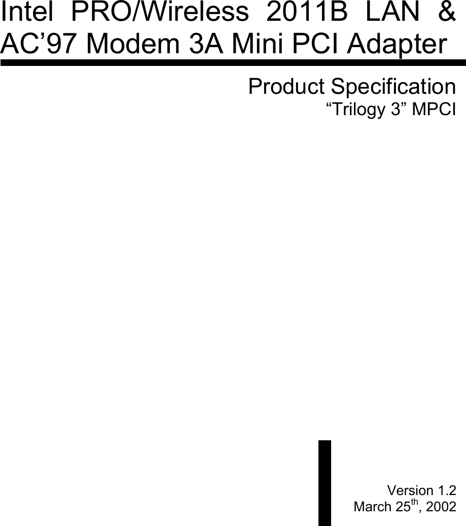

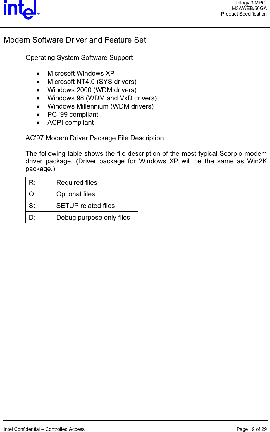
![Trilogy 3 MPCI M3AWEB/56GA Product Specification Table 2. [ltsetup.ini] [INSTALL_OPTIONS] Section defines all the installation options. ;File version 1.37 Setup program version Debug=N Debug=Y will enable debug mode operation. WDMDriver=N WDMDriver=Y will install WDM driver for Win98SE instead of VxDs. ReBoot=N For W9x/ME/2K/XP, ReBoot=Y will prompt user to reboot the system after installing the driver. (NT4 will always ask to reboot the system.) CleanUpRegistry=Y Enable clean up the registry keys specified in [CLEANUPPATH] section. CopyFilesW2K=N In W2K, copy files only, does not refresh the system. (Should not be documented later.) ;SilentInstall=Y Enable silent install mode. ;CabsFlag=Y Enable ltremove to set SourcePath to \Windows\options\cabs for WinME. It is set to \windows\options\install by default. ;CatFlag=Y Enable to use SetupCopyOemInf to copy W2K INF files. CabExtract=N Enable cab file extraction feature upon installing modem driver. [COPY_FILES_9X] ;FILE0=filename1, $windows\system FILE1=ltremove.exe Section allows copying specific files (to specific locations) other than default driver/INF/exe in Win9x. [COPY_FILES_NT] FILE0=ltmsg.exe FILE1=ltremove.exe ;FILE2=filename1, $windows\system32 Section allows copying specific files (to specific locations) other than default driver/INF/exe in NT4. [COPY_FILES_Win2K] ;FILE0=ltmsg.exe FILE1=ltremove.exe ;FILE2=filename, $windows\system32 Section allows copying specific files (to specific locations) other than default driver/INF/exe in W2K/XP. [DELETE_FILES_9X] FILE0=ageresoftmodem.htm, $windows Section allows deleting specific files upon uninstallation of the modem driver in Win9x. [DELETE_FILES_NT] FILE0=ageresoftmodem.htm, $windows Section allows deleting specific files upon uninstallation of the modem driver in NT4. [DELETE_FILES_Win2K] FILE0=ageresoftmodem.htm, $windows Section allows deleting specific files upon uninstallation of the modem driver in W2K/XP. [LAUNCH_FILES_9X] FILE0=lthomol.exe Section allows launching specified executable (at specific directory location) upon installation of the Intel Confidential – Controlled Access Page 22 of 29](https://usermanual.wiki/Quanta-Computer/M3AWEB/User-Guide-275640-Page-22.png)
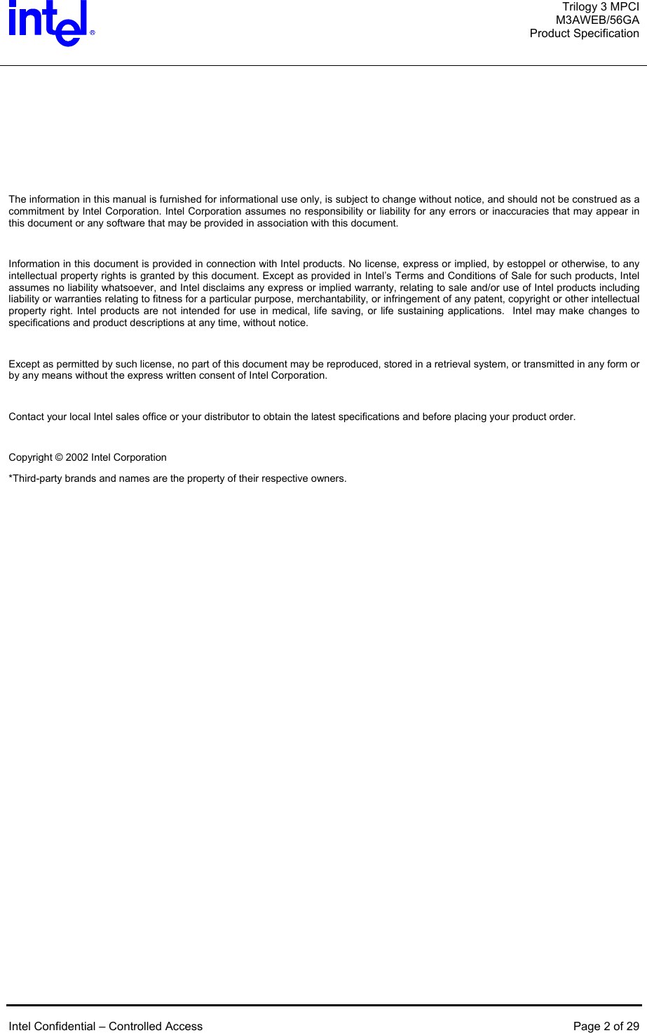
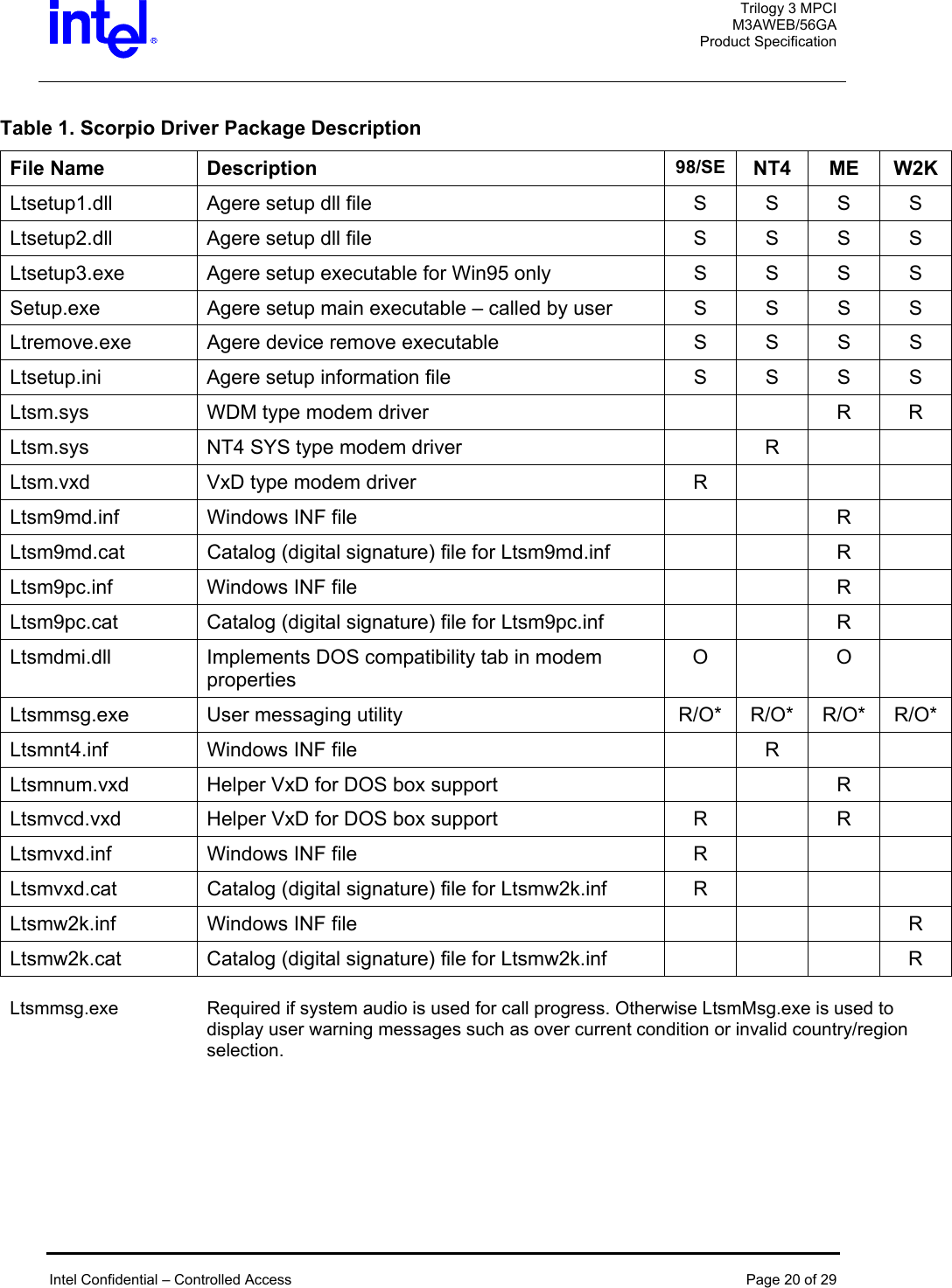
![Trilogy 3 MPCI M3AWEB/56GA Product Specification ;FILE1=filename arg1 arg2, $windows\system specific directory location) upon installation of the modem driver in Win9x. [LAUNCH_FILES_NT] FILE0=lthomol.exe ;FILE1=filename arg1 arg2, $windows\system32 Section allows launching specified executable (at specific directory location) upon installation of the modem driver in NT4. [LAUNCH_FILES_Win2K] FILE0=lthomol.exe ;FILE1=filename arg1 arg2, $windows\system32 Section allows launching specified executable (at specific directory location) upon installation of the modem driver in W2K/XP. [IDS_TO_BE_INSTALLED] id0=10B9&DEV_5450 id1=1039&DEV_7013 id2=8086&DEV_2446 id3=8086&DEV_2486 id4=8086&DEV_7196 id5=1106&DEV_3068 Specify the motherboard chipset IDs (PCI vendor ID and device ID) which the modem is installed to (up to 20 IDs). [CLEANUPPATH] Path0="Software\\Lucent\\SoftModem" Specify the registry path to be clean up upon uninstallation of modem driver. [REGDELKEYS] Path0="Software\\Lucent" Specify the registry keys for modem uninstallation. [CABNAME] Cabname=agrsm.cab Specify the cab file being extracted by setup. [CABPATH] ;path="C:\ageresoftmodemhelp” Path="C:\Program Files\agere\scorpio" ;path="C:\cabxtracts" Specify the directory location where the cab file is being extracted. Setup will create the sub directory by itself assuming parent directory already exists in the system. (i.e. \scorpio should be created under existing directory C:\Program Files\agere ) Intel Confidential – Controlled Access Page 23 of 29](https://usermanual.wiki/Quanta-Computer/M3AWEB/User-Guide-275640-Page-23.png)
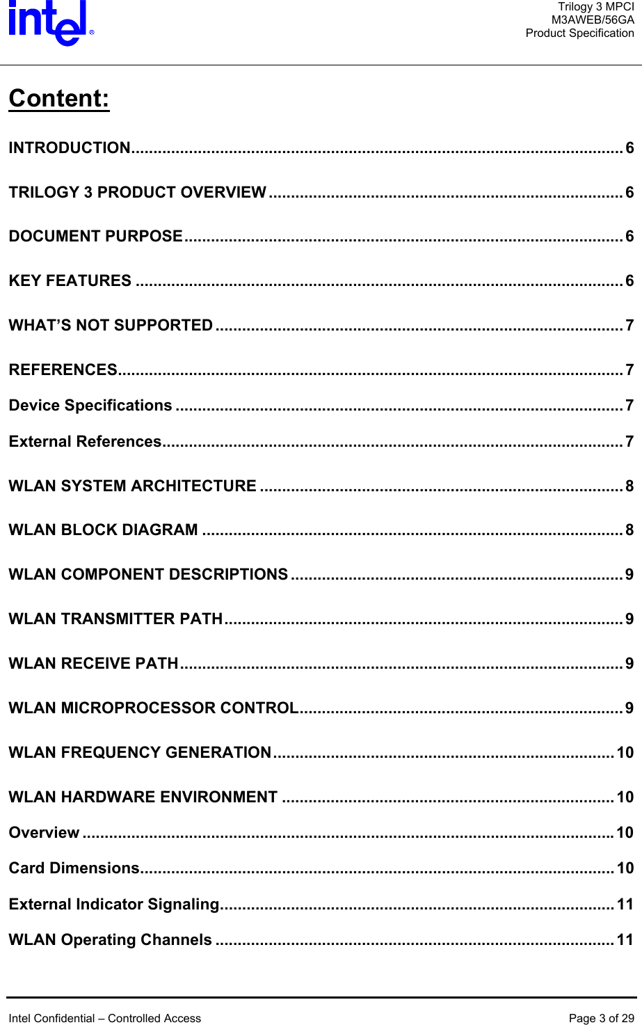
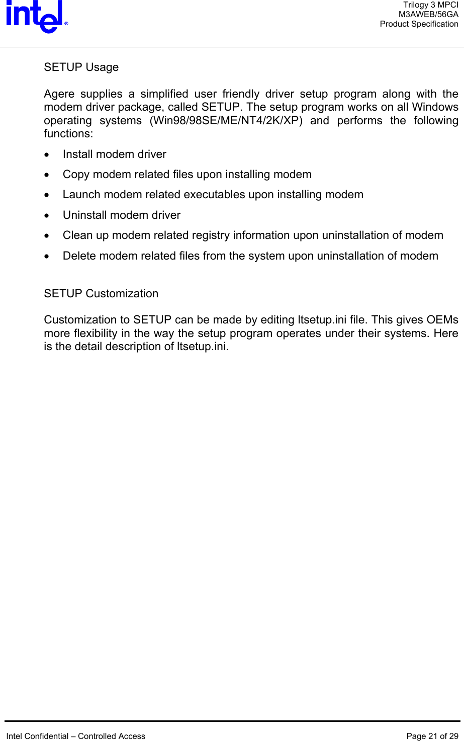
![Trilogy 3 MPCI M3AWEB/56GA Product Specification LTHOMOL.exe (Homologation support utility) Agere Scorpio modem offers worldwide support over 60 country/region modes. This homologation capability is enabled by the certain modem hardware (DAA - analog front-end design) and the software (Device driver). The device driver configures various parameters and sets the modem to function under certain telecommunication regulation and laws to pass PTT approvals. This capability allows PC OEMs and retail manufactures to market their products in more countries/regions. It will also enables end-users to have more mobility of the modem usage in laptop PC environments. While over 100 homologation parameters have their default values configured in the modem driver, LTHOMOL.exe adds the capability to modify/update the parameters that matches with the certain modem hardware to be installed. ;This section allows to patch existing country settings or add new country. ;format is Snnn=defaultValue,minValue,maxValue ;minValue and maxValue are ignored for debug registers (>=500) ;[B5] Country/Region code ;S0=4,4,8 Parameter S0 ;S516=0x21 Parameter S516 ; ;This section allows to disable support for specific countries. : ;[Disable_Country] ;0A ;0F ;B6 For the detail of the country/region codes and homologation parameters settings, please refer to Lucent Technologies Homologation Parameter Values for the LU97 Soft Modem Chip Set manual (Jan/2001). Intel Confidential – Controlled Access Page 25 of 29](https://usermanual.wiki/Quanta-Computer/M3AWEB/User-Guide-275640-Page-25.png)
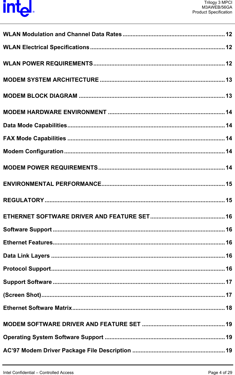
![Trilogy 3 MPCI M3AWEB/56GA Product Specification LTSMMSG.exe (User messaging & system audio support utility) LTSMMSG.exe is a stand-alone program that offers you to show pop-up windows to indicate users for certain critical events occurred, while users are using the modem function. This program supports all Windows operating systems. Selection of Un-homologated Country Messaging If the user selects some country which the modem is not homologated, either from Regional Settings and/or Modem, Dialing Properties, My Location in Control Panel, this warning message will show up. Modem is not approved in the selected country. Selecting a country other than the one in which you are currently located may cause your modem to be configured in a way that violates the telecommunication regulations/laws of that country. In addition, your modem may not function properly if the correct country selection is not made. Only select the country in which you are located. Country/region setting of the modem will remain the same as it was before if an un-homologated country/region is selected. In addition the modem function itself will not be blocked by this program. To enable this feature the following line is needed in the INF file(s) for each operating system. [PortMod.AddReg] HKLM,SOFTWARE\Microsoft\Windows\CurrentVersion\Run,LTSMMSG,,LTSMMSG.exe (Launch LTSMMSG.exe upon Windows boot-up.) Intel Confidential – Controlled Access Page 26 of 29](https://usermanual.wiki/Quanta-Computer/M3AWEB/User-Guide-275640-Page-26.png)
![Trilogy 3 MPCI M3AWEB/56GA Product Specification Over Current Protection (OCP) Messaging When the user is on the road or even at home and accidentally plugs modem into RJ-11 jack that is a digital PBX line, the modem will not go off hook to protect the modem hardware to be damaged by high voltage/current line condition. Upon off hook event, the following warning message will show up. “The modem is plugged into a digital PBX line and will not work.” The modem hardware has to equip the over current protection circuit to support this feature. To enable this feature the following line is needed in the INF file(s) for each operating system. [PortMod.AddReg] HKLM,SOFTWARE\Microsoft\Windows\CurrentVersion\Run,LTSMMSG,,LTSMMSG.exe (Launch LTSMMSG.exe upon Windows boot-up.) Intel Confidential – Controlled Access Page 27 of 29](https://usermanual.wiki/Quanta-Computer/M3AWEB/User-Guide-275640-Page-27.png)
![Trilogy 3 MPCI M3AWEB/56GA Product Specification System Audio Support LTSMMSG.exe also serves as a Windows user mode ring-3 application which samples audio data stream generated by the driver and transfers the data onto the system audio device. This will allow the system to support call progress tone monitor function without using PWM (Pulse Width Modulation) speaker function that is previously supported. This new feature eliminates the external components (circuit) required for PWM speaker support and will help reducing the BOM (Bill of Material) and the size of the modem hardware. To enable this feature the following line is needed in the INF file(s) for each operating system. (Example of system audio support in Intel Solano2 system) [Lucent_Modems] %INTEL_AMR.Modem% = INTEL_AMR_SA.Modem, PCI\VEN_8086&DEV_2446&SUBSYS_12345678 (INTEL_AMR_SA.Modem entry enables system audio support in Intel system.) [ControlFlags] ExcludeFromSelect = PCI\VEN_8086&DEV_2446&SUBSYS_12345678 (Match the ID string with above [Lucent_Modems] ID entry.) [PortMod.AddReg] HKLM,SOFTWARE\Microsoft\Windows\CurrentVersion\Run,LTSMMSG,,LTSMMSG.exe HKLM,SOFTWARE\Lucent\SoftModem,CallProgressPlayThreshold,1,a0,1f,00,00 (Launch LTSMMSG.exe upon Windows boot-up and specify the audio sample playback latency.) If the PC OEM requires just the system audio support, the following line will disable user messaging functions in the INF file(s) for each operating system. [PortMod.AddReg] HKLM,SOFTWARE\Lucent\SoftModem,SoftModemMsgDisable,1,FF,FF,FF,FF This system audio support is officially implemented from version 3.1.90 release and onward. Intel Confidential – Controlled Access Page 28 of 29](https://usermanual.wiki/Quanta-Computer/M3AWEB/User-Guide-275640-Page-28.png)