Quanta Computer M3AWEB WLAN Module User Manual Trilogy 3 MPCI
Quanta Computer Inc WLAN Module Trilogy 3 MPCI
Manual

Intel PRO/Wireless 2011B LAN &
AC’97 Modem 3A Mini PCI Adapter
Product Specification
“Trilogy 3” MPCI
Version 1.2
March 25th, 2002

Trilogy 3 MPCI
M3AWEB/56GA
Product Specification
The information in this manual is furnished for informational use only, is subject to change without notice, and should not be construed as a
commitment by Intel Corporation. Intel Corporation assumes no responsibility or liability for any errors or inaccuracies that may appear in
this document or any software that may be provided in association with this document.
Information in this document is provided in connection with Intel products. No license, express or implied, by estoppel or otherwise, to any
intellectual property rights is granted by this document. Except as provided in Intel’s Terms and Conditions of Sale for such products, Intel
assumes no liability whatsoever, and Intel disclaims any express or implied warranty, relating to sale and/or use of Intel products including
liability or warranties relating to fitness for a particular purpose, merchantability, or infringement of any patent, copyright or other intellectual
property right. Intel products are not intended for use in medical, life saving, or life sustaining applications. Intel may make changes to
specifications and product descriptions at any time, without notice.
Except as permitted by such license, no part of this document may be reproduced, stored in a retrieval system, or transmitted in any form or
by any means without the express written consent of Intel Corporation.
Contact your local Intel sales office or your distributor to obtain the latest specifications and before placing your product order.
Copyright © 2002 Intel Corporation
*Third-party brands and names are the property of their respective owners.
Intel Confidential – Controlled Access
Page 2 of 29

Trilogy 3 MPCI
M3AWEB/56GA
Product Specification
Content:
INTRODUCTION............................................................................................................... 6
TRILOGY 3 PRODUCT OVERVIEW ................................................................................ 6
DOCUMENT PURPOSE................................................................................................... 6
KEY FEATURES .............................................................................................................. 6
WHAT’S NOT SUPPORTED ............................................................................................ 7
REFERENCES.................................................................................................................. 7
Device Specifications ..................................................................................................... 7
External References........................................................................................................ 7
WLAN SYSTEM ARCHITECTURE .................................................................................. 8
WLAN BLOCK DIAGRAM ............................................................................................... 8
WLAN COMPONENT DESCRIPTIONS ........................................................................... 9
WLAN TRANSMITTER PATH.......................................................................................... 9
WLAN RECEIVE PATH.................................................................................................... 9
WLAN MICROPROCESSOR CONTROL......................................................................... 9
WLAN FREQUENCY GENERATION............................................................................. 10
WLAN HARDWARE ENVIRONMENT ........................................................................... 10
Overview ........................................................................................................................10
Card Dimensions........................................................................................................... 10
External Indicator Signaling......................................................................................... 11
WLAN Operating Channels .......................................................................................... 11
Intel Confidential – Controlled Access
Page 3 of 29

Trilogy 3 MPCI
M3AWEB/56GA
Product Specification
WLAN Modulation and Channel Data Rates ............................................................... 12
WLAN Electrical Specifications ...................................................................................12
WLAN POWER REQUIREMENTS................................................................................. 12
MODEM SYSTEM ARCHITECTURE ............................................................................. 13
MODEM BLOCK DIAGRAM .......................................................................................... 13
MODEM HARDWARE ENVIRONMENT ........................................................................ 14
Data Mode Capabilities................................................................................................. 14
FAX Mode Capabilities ................................................................................................. 14
Modem Configuration ...................................................................................................14
MODEM POWER REQUIREMENTS.............................................................................. 14
ENVIRONMENTAL PERFORMANCE............................................................................ 15
REGULATORY ............................................................................................................... 15
ETHERNET SOFTWARE DRIVER AND FEATURE SET.............................................. 16
Software Support .......................................................................................................... 16
Ethernet Features.......................................................................................................... 16
Data Link Layers ...........................................................................................................16
Protocol Support...........................................................................................................16
Support Software .......................................................................................................... 17
(Screen Shot).................................................................................................................17
Ethernet Software Matrix.............................................................................................. 18
MODEM SOFTWARE DRIVER AND FEATURE SET ...................................................19
Operating System Software Support .......................................................................... 19
AC’97 Modem Driver Package File Description ......................................................... 19
Intel Confidential – Controlled Access
Page 4 of 29

Trilogy 3 MPCI
M3AWEB/56GA
Product Specification
SETUP Usage ................................................................................................................21
SETUP Customization ..................................................................................................21
Multilanguage Support ................................................................................................. 24
LTHOMOL.exe (Homologation support utility)........................................................... 25
LTSMMSG.exe (User messaging & system audio support utility) ...........................26
Selection of Un-homologated Country Messaging.................................................... 26
Over Current Protection (OCP) Messaging ................................................................ 27
System Audio Support ................................................................................................. 28
QUALITY ........................................................................................................................29
Product design requirements ...................................................................................... 29
Environmental requirements ....................................................................................... 29
Statistical tool................................................................................................................ 29
Product manufacturing requirements......................................................................... 29
Product qualification .................................................................................................... 29
Post-launch product health through end of life ......................................................... 29
Intel Confidential – Controlled Access
Page 5 of 29

Trilogy 3 MPCI
M3AWEB/56GA
Product Specification
Introduction
The primary purpose of this document is to communicate the Intel PRO/Wireless LAN &
AC’97 Modem MPCI Adapter features and specifications to a technical audience.
Trilogy 3 is an Intel codename that references a third generation of wireless LAN
products that are OEMed-in from Symbol Corporation, or based on Intersil Prism 2.5
reference designs. The WLAN and Modem sections of the adapter are completely
separate – including power and interface pins, allowing a WLAN-only version via de-
population of modem components.
Trilogy 3 Product Overview
Trilogy 3 products transfer data at ethernet speeds (11Mbps instantaneous data rate)
over the air between two or more users or between a user and the wired network. The
WLAN is not a single product; it is a digital radio system with product components that
can be configured to meet a multitude of customer requirements. The Trilogy 3 Access
Point (AP) links to a wired LAN via a wired ethernet connection. Wireless NICs
communicate to the wired LAN through the AP. Multiple Access Points are deployed in
a cellular layout plan similar in concept to the cellular telephone base station layout.
Document Purpose
This document defines the functional characteristics of the Trilogy 3 MPCI Adapter. All
of the basic functionality is provided by Intersil as part of their 802.11 DS implementation
for the Intersil PRISM 2.5 radio using the Intersil ISL3874A microcontroller. In particular,
the host interface access mechanisms, packet send, receive, queuing, timer services,
and buffer management are already implemented and do not require further
development. Therefore, this document primarily addresses the radio configuration and
firmware enhancements required for the Trilogy 3 product.
Key Features
• Direct Sequence 802.11b physical layer
• 802.11b High data rate capability – 11 MBPS, 5.5 MBPS, 2 and 1 MBPS
• 3.3 volt Mini PCI Type 3A card (3.3V Aux – Modem)
• 16 bit host interface using PCI IO mode for 802.11b section
• In-line WEP algorithm
• Enhanced power save algorithm for 802.11b section
• Robust roaming and dynamic rate switching for 802.11b section
• Wi-Fi certified 802.11b section
• Microsoft WHQL certified
• Modem Auto-configuration
• Modem v.90 Compliant (software-upgradeable to v.92)
• Hayes Compatible AT modem command set
• Modem Wake On Ring
Intel Confidential – Controlled Access
Page 6 of 29

Trilogy 3 MPCI
M3AWEB/56GA
Product Specification
What’s Not Supported
• The 802.11b firmware does not currently support a low power mode of operation
(< 20 ma). For Idle mode, it removes power to as many circuits as possible, but
the current level of firmware implementation prevents the ISL3874A controller
from using a 32 KHz low power oscillator for sleep mode. Since the controller
and clock will always be active the driver does not require wake-up/resume
operations (although the adapter will consume as little power as possible when
there are no receive, transmit, internal (roam) or host activities in progress.)
• Wake-On-LAN operation is not supported for the 802.11b section of this product.
This is due to the fact that the Intersil chipset does not support 3.3VAUX
detection.
• A hardware “Radio-Disable” switch is not supported for the 802.11b section;
however a software-implemented function is provided to disable radio
transmissions.
• There is no output pin to display 802.11b Activity status via an LED. Displaying
Activity Status is not supported with the current revision of the Intersil chipset and
firmware at this time. Future plans for support of this feature in Intel’s 802.11b
MPCI product are TBD as of Revision 1.2 of this document.
References
Device Specifications
• ISL 3874A Direct Sequence Spread Spectrum Integrated MAC and
Baseband Processor, Intersil Semiconductor, May, 2001
• HFA 3783 I/Q Modem and Synthesizer, Intersil, November, 2000
• ISL 3685 RF/IF Converter and Synthesizer, Intersil, January, 2001
• ISL 3984 RF Power Amplifier and Detector, Intersil, December, 2000
• CY62136V - 128K by 16 Static RAM, Cypress Semiconductor Corporation,
September, 2000
• SST 39VF010 128K by 8 bit CMOS FLASH, Silicon Storage Technology, Inc.,
2000
• CSP1037 AC-Link Soft Modem Data Sheet, Rev. 1, October 2001, Agere
Systems Inc.
External References
• Wireless LAN Medium Access Control (MAC) and Physical Layer (PHY)
Specifications, ISO/IEC 8802-11:1999(E)
• Higher-Speed Physical Layer Extension in the 2.4 GHz Band, IEEE Std
802.11b-1999
• Audio Codec ’97, Rev. 2.2, September, 2000, Intel Corporation
• Mini PCI Specification, Rev. 1.0, October 25, 1999, PCI Special Interest
Group
Intel Confidential – Controlled Access
Page 7 of 29
Trilogy 3 MPCI
M3AWEB/56GA
Product Specification
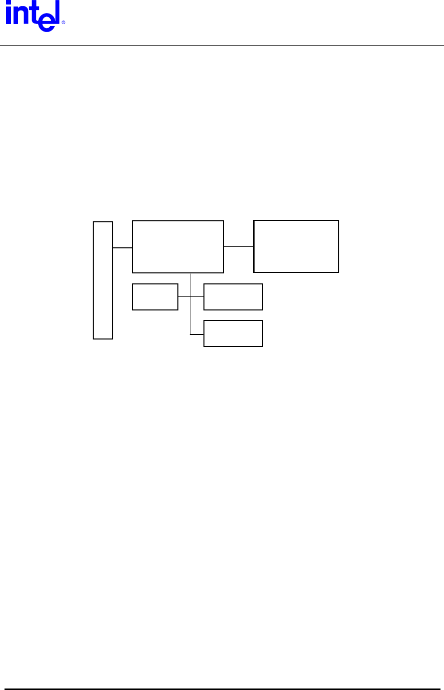
WLAN System Architecture
The WLAN section of the adapter consists of a 2.4 GHz radio with direct sequence
transmit and receive circuitry using Intersil 3874A Integrated MAC and Base Band
Processor and ISL3685/HFA3783 Intersil radio chipset. The controller circuitry consists
of the Intersil ISL3874A MAC controller with PCI interface, Flash and SRAM.
Crystal oscillators are used to drive the controller and transmit/receive circuits. Power
control circuits are used to selectively enable radio circuitry. Power on reset is
accomplished via a Maxim 6326 Reset IC, and with resistors to select default
configuration parameters and to put circuits into the off state until the firmware has
enabled the outputs from the controller.
Radio
Prism 2.5 Based
SRAM
ISL3874A
Micro- Controller
FLASH Clock
Mini PCI Host I/F
WLAN Block Diagram
The ISL3874A microcontroller section executes under firmware control to process radio,
timer and host events/operations. This chip executes RISC-type instructions in one clock
using a 3-stage pipeline. The chip supports up to 8 active contexts. Context switching
occurs when higher priority events cause an “instant” switch to the appropriate higher
priority context. Contexts can be configured as “foreground” or “background”, where
foreground contexts always have priority, and background contexts operate in a round-
robin fashion. When there are no eligible contexts, the device consumes very little
power. Up to 64 K words of control store and 8 M bytes of RAM buffers are accessible
by the CPU address registers.
All firmware executes from the control store address space in the SRAM in order to
provide the required throughput for 11 MBPS data rates. The 256 KB SRAM supports
low memory variables and host interface, as well as a linked list of send/receive buffers
and host configuration buffers. The upper half of SRAM is used to store the executable
control store code.
The Host PCI interface accesses memory/registers via the ISL3874A controller;
Command/Status registers and Buffer Access Paths are provided to support a simple,
fast interface mechanism. The radio card includes the Direct Sequence send/receive
circuitry, RF synthesizers, reference oscillator, and power switching circuits.
Intel Confidential – Controlled Access
Page 8 of 29

Trilogy 3 MPCI
M3AWEB/56GA
Product Specification
WLAN Component Descriptions
The Intel PRO/Wireless 2011B LAN Mini PCI uses the Intersil Corp. Prism 2.5 Chipset to
implement the spreading, modulation, demodulation and de-spreading. The RF up- and
down-conversion approach is the common superhetrodyne architecture with integrated
chip set (ISL3685/HFA3783) manufactured by Intersil. The channel frequency, fc, is
created (transmit) or converted (receive) by mixing with a low side LO frequency, flo, to
the 374 MHz IF (fc= flo + 374 MHz). The 374 MHz IF is converted to/from baseband
using the Intersil I/Q modulator demodulator HFA3783 IC.
WLAN Transmitter Path
The Intersil ISL3874A baseband processor section creates the transmit waveform and
outputs the signal on the TX I/Q lines. The Intersil HFA3783 up-converts the transmit
baseband signal to 374 MHz. To control the side lobes the transmit signal is passed
through a SAW filter (374 MHz center, 22 MHz BW). The signal is then amplified and
mixed up to the channel frequency using Intersil ISL3685 IC. The LO frequency is
lowside (fc – 374M). The signal is then band-pass filtered, amplified, and low-pass
filtered (2.4 to 2.5 GHz passband) to create the required output power while keeping
spurious and harmonic emissions in spec. Two switches are incorporated at the output
to provide for antenna diversity and receive/transmit switching.
WLAN Receive Path
The receive signal passes through the front-end diversity and transmit/receive switches.
The signal is band-pass filtered and then amplified by Intersil ISL3685 and then down-
converted to 374 MHz. The LO frequency is lowside (fc – 374M). The receive signal is
passed through the SAW to provide adjacent channel selectivity. The Intersil HFA3783
creates the baseband I/Q signals and the signal is de-spread and demodulated in the
Intersil ISL3874A.
WLAN Microprocessor Control
The Intersil ISL3874A micro-controller section along with flash and SRAM memory
control the transmitter and receiver. The micro-controller section is derived from the
Intersil HFA3842 and is clocked at 14.67 MHz by a PLL-divided 44 MHz crystal. The
micro-controller along with the embedded firmware runs the 802.11 Media Access
Control (MAC) layer control. The MAC control sends and receives packets and transfers
data to and from the PCI interface to the host computer. The host computer in which the
Mini-PCI is embedded can be a handheld, notebook or fixed computer.
Intel Confidential – Controlled Access
Page 9 of 29
Trilogy 3 MPCI
M3AWEB/56GA
Product Specification
WLAN Frequency Generation
The first and second LO are generated by two external VCOs. The first LO feeds the
Intersil ISL3685 to generate the channel frequency minus 374 MHz. The second LO
which feeds the Intersil HFA3783 is 2 times 374 MHz (748 MHz). A 44 MHz crystal is the
reference for the synthesizers. The synthesizers are controlled by the ISL3874A micro-
controller section.
WLAN Hardware Environment
Overview
The Intel PRO/Wireless 2011B LAN Mini PCI Adapter can be used in handheld,
notebook or fixed computers to provide wireless network access. The Adapter
communicates over the air between two or more users or between a user and the
wired network.
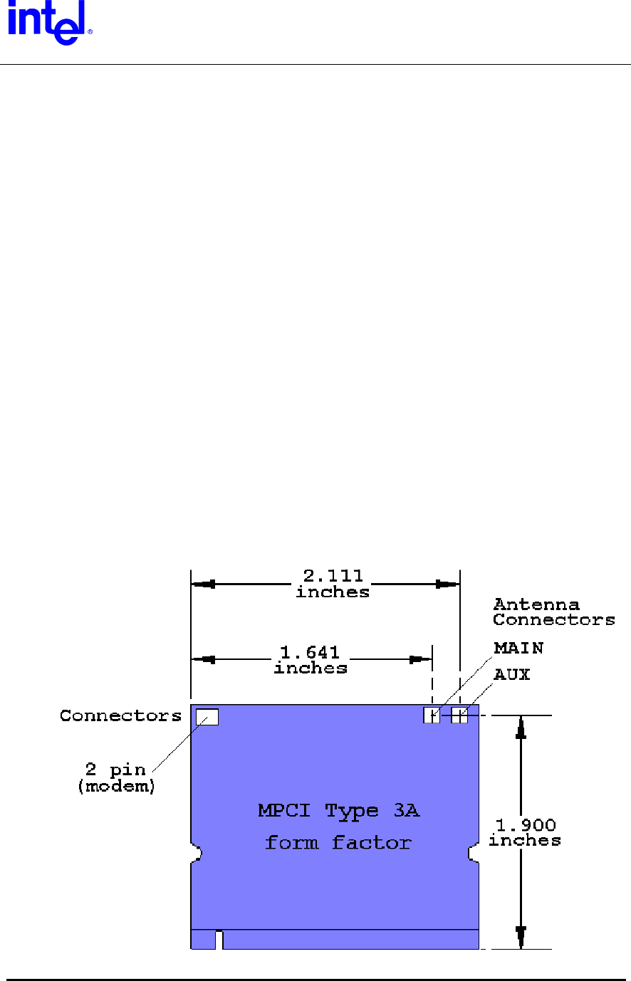
Card Dimensions
The Intel PRO/Wireless 2011B LAN Mini PCI Adapter complies with the
dimensional specifications of a Mini PCI Type 3A card. The maximum
dimensions are: height 50.95 mm (2.006 inches,) width 59.75 mm (2.352 inches,)
and thickness 4.9 mm (0.193 inches.)
Intel Confidential – Controlled Access
Page 10 of 29

Trilogy 3 MPCI
M3AWEB/56GA
Product Specification
The 2-pin modem connector meets the physical requirements of and is located
per the Mini-PCI specification. Antenna connectors are located as shown in the
above drawing. They are Hirose type U.FL-R-SMT.
External Indicator Signaling
Signals are provided to drive up to 2 external LAN Status LEDs. These signals
are available in one of two different configurations via the bottom System
Connector (SC) pins. All signals, whether positive or negative drive, can supply
6mA of current.
System Connector
Pinouts by Configuration
Signal
Name
Functional
Description
Drive
Polarity Standard Option B
Power Power applied to
Adapter
Positive NA 12+/(No -)
Link
Flashing: Scanning
On Solid: Associated
Negative
11+/13-
NA
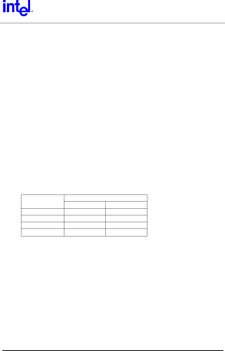
WLAN Operating Channels
The FCC (US), IC (Canada), and ETSI (Europe) specify operation from 2.4 GHz
to 2.4835 GHz.
The channels used are:
Channel
Center
Frequency
(MHz)
Start
Frequency
(MHz)
End
Frequency
(MHz)
1 2412 2400 2424
2 2417 2405 2429
3 2422 2410 2434
4 2427 2415 2439
5 2432 2420 2444
6 2437 2425 2449
7 2442 2430 2454
8 2447 2435 2459
9 2452 2440 2464
10 2457 2445 2469
11 2462 2450 2474
12 2467 2455 2479
13 2472 2460 2484
14 2483 2471 2495*
Highlights denote 3 most commonly used (non-overlapping) Ch’s in the U.S.
*Japan specifies 2.483 to 2.495 for Channel 14.
Intel Confidential – Controlled Access
Page 11 of 29
Trilogy 3 MPCI
M3AWEB/56GA
Product Specification
WLAN Modulation and Channel Data Rates
Four modulation formats and data rates are specified by the IEEE 802.11b
specification. The basic access rate is based on 1 Mbit/s Differential Binary
Phase Shift Keying (DBPSK) modulation. The enhanced access rate is based on
2 Mbit/s Differential Quaternary Phase Shift Keying (DQPSK). The extended
Direct Sequence specification defines two additional data rates. These rates are
based on the Complementary Code Keying (CCK) modulation scheme for 5.5
Mbit/s and 11 Mbit/s.
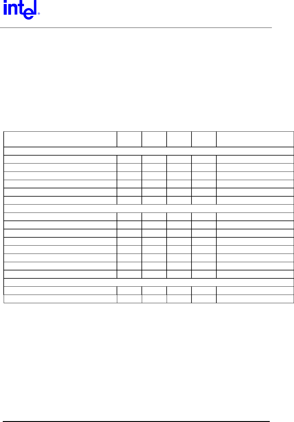
WLAN Electrical Specifications
Description MAX TYP MIN Unit Comments
Functional
3.3v 802.11 Sleep Current 100 65 mA Sleep portion only
3.3v Transmit Current 385 300 mA
3.3v Receive Current 350 200 mA
3.3V Idle Current 200 150 mA 11b Sleep mode avg.
Frequency Tolerance 0C to 55C +25 -25 PPM
Frequency Tolerance -10C to 70C -25 +25 PPM
Receiver
Sensitivity, 11 Mbps, 25C -85 -82 dBm 8% PER 1024 Octets
Sensitivity, 5.5 Mbps, 25C -88 -85 dBm 8% PER 1024 Octets
Sensitivity, 2 Mbps, 25C -91 -88 dBm 8% PER 1024 Octets
Sensitivity, 1 Mbps, 25C -94 -91 dBm 8% PER 1024 Octets
Sensitivity, 11 Mbps, -10C to 70C -82 -80 dBm 8% PER 1024 Octets
Sensitivity, 5.5 Mbps, -10C to 70C -85 -83 dBm 8% PER 1024 Octets
Sensitivity, 2 Mbps, -10C to 70C -88 -86 dBm 8% PER 1024 Octets
Sensitivity, 1 Mbps, -10C to 70C -91 -89 dBm 8% PER 1024 Octets
Transmitter
Power Level, 25C 15.4 dBm Max. Power - Default
Power Level, -10C to +70C 14 dBm Max. Power - Default
WLAN Power Requirements
The Adapter is able to work with the standard Mini-PCI 3.3V +/- 5% power source. The
Adapter’s current consumption depends on the operating state. The operating state is
controlled by the Adapter’s driver software and the Adapter’s CPU. The pulse
characteristics, and peak inrush current depend on the capacitance and resistance of
the host power supply. The Adapter presents a capacitive load of approximately 20 uF.
Noise on the 3.3 V power supply should be below 50 mV RMS.
Intel Confidential – Controlled Access
Page 12 of 29
Trilogy 3 MPCI
M3AWEB/56GA
Product Specification
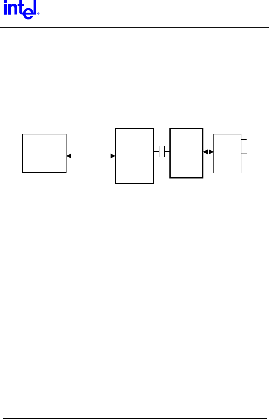
Modem System Architecture
The 56K soft modem design is based on the Agere CSP1037 Scorpio chip set. This
chip set includes an integrated direct access arrangement (DAA) that provides a
programmable line interface to meet international telephone line requirements.
Unlike Controller or Controller-less modems, the AC’97 soft modem uses host CPU
computing power to process the incoming/outgoing data instead of having a dedicated
DSP local to the modem.
Isolation Barrier
Host Side Line Side Hook- Tip
Mini PCI AC’97 Device Device Switch
Host I/F Signals and Ring
SCP-16T CSP1037 DC
-16T Term.
Modem Block Diagram
Host Side (SCP-16T) has the AC’97 link protocol built-in for communication to the Host.
It is responsible to process data coming in and going out to the Line Side chip as well as
commands to control the Line Side for on-hook, off-hook, dial, ring detect. The host side
can be configured via Host Interface strapping pins as an AC’97 Primary (ID 00) or
Secondary (ID’s 01 or 10) Codec. For the (default) Primary mode, an on-board
24.576MHz oscillator is provided which is converted to the required internal and external
clock frequencies by a PLL within the Host Side chip. An analog Call-Progress signal is
provided at one of two Host Interface pins. Power for the digital portion of the Host Side
is provided by the host system’s 3.3VAUX supply. Power for the analog portion is
provided by a charge pump, which is driven by the data-stream of the isolation barrier.
The Scorpio chip set achieves an isolation barrier through low-cost, high-voltage
capacitors in conjunction with Agere’s proprietary signal processing techniques. These
techniques eliminate any signal degradation due to capacitor mismatches, common-
mode interference, or noise coupling. All transmit, receive, control, and ring detect data
are communicated through this barrier.
Line Side (CSP1037-16T) communicates data with the Host Side across the capacitive
barrier. The Line Side chip performs D/A and A/D conversion, provides the DAA
functions such as AC and DC impedance control, ring detection, and loop current
monitoring. This chip also controls the analog input/output to Tip/Ring via discrete
components. Power for the Line Side is derived from the telephone line.
The hook-switch and DC termination circuits of the DAA are implemented with discrete
transistors and passive components, controlled by the Line Side chip.
Intel Confidential – Controlled Access
Page 13 of 29
Trilogy 3 MPCI
M3AWEB/56GA
Product Specification
Modem Hardware Environment
Data Mode Capabilities
• V.90 Compliant (software-upgradeable to v.92)
• ITU-T V.34 extended rates: 33600 bits/s - 2400 bits/s
• V.32terbo, V.32bis, and fallbacks
• TIA/EIA 602 standard for AT command set
• V.42 error correction (LAPM and MNP)
• V.42bis and MNP Class 5 data compression
• V.25 & V.25ter
• V.8bis signaling
• Bell 103J
• Bell 212A
FAX Mode Capabilities
• ITU-T V.17, V.29, V.27ter, and V.21 Ch 2
• TIA/EIA 578 Class 1 FAX
Modem Configuration
The AC’97 Primary / Secondary Codec addressing configuration is the
responsibility of the OEM via motherboard strapping of the System Connector
(SC) ID pins.
SC Conn. Pin Strapping
AC’97 Address
Mode ID 1 (Pin 109) ID0 (Pin 108)
Primary (00) High or Open High or Open
Secondary 01 High or Open Low
Secondary 10 Low High or Open
Secondary 11 Not Supported Not Supported
An analog audio Call Progress signal is provided at (only) one pin of the SC.
Whichever pin is not used for this function will be a NC (Open-circuit).
Standard Audio Output pin: 111 (MOD_AUDIO_MON)
Optional pin (Option C): 116 (SYS_AUDIO_IN)
Modem Power Requirements
The Adapter requires the standard Mini-PCI 3.3VAUX +/- 5% power source. The
Adapter’s current consumption depends on the operating state. The operating state is
controlled by the Adapter’s driver software and the Adapter’s CPU. The pulse
characteristics, and peak inrush current depend on the capacitance and resistance of
the host power supply. The Adapter presents a capacitive load of approximately 10 uF.
Noise on the 3.3 VAUX power supply should be below 50 mV RMS.
Intel Confidential – Controlled Access
Page 14 of 29
Trilogy 3 MPCI
M3AWEB/56GA
Product Specification
Environmental Performance
Environment Limits
Storage Temperature -30 ºC to +80 ºC
Operating Temperature 0 ºC to 65 ºC Nominal Temperature Range
-10 ºC to +70 ºC Extended Temperature Range
Humidity 95%, Non-Condensing
Altitude Altitude: up to 2.4 km
ESD +/-15 kV, Air / +/-8 kV, Contact / +/-2 kV, Pin
Power Supply Noise &
Interference
70 mV rms from 50 Hz to 70 Hz and 50 mV rms 70 Hz
to 400 MHz,
Vibration, Shock, Torque, Drop,
Dust, Rain & Drip.
TBD
Regulatory
Regulatory agency approval requirements for this product are FCC, CE, and UL. (Other
regulatory requirements on a per country/application basis).
Certifications
U.S./Canada: FCC Part 15 Class B US
Unintentional Emissions. FCC Part 15.247,
15.205, 15.209
Canada DOC RSS-210 Canadian Spread
Spectrum
Europe: ETS 300 328, ETS 300 826, CE
Marked
Japan: RCR STD-33
Safety Compliance
USA/Canada: UL1950/CSA 22.2
Europe: CE Marked
Standard for Operation: Conforms to 802.11b specifications
Standard for Interoperability: Wireless Ethernet Compatibility Alliance (WECA)
Intel Confidential – Controlled Access
Page 15 of 29

Trilogy 3 MPCI
M3AWEB/56GA
Product Specification
Ethernet Software Driver and Feature Set
The software driver set is a major software release designed to support the features of
the 80211b Ethernet controller used on the Intel M3AWEB/56GA Mini-PCI Combo Card
product. The level of driver support is described in the following sections.
Software Support
• Microsoft NT4.0
• Windows 2000
• Windows 98 and 98SE
• Windows Millennium
• Windows XP
Ethernet Features
• 802.11b 11 Mbps,5.5 Mbps,2 Mbps,1 Mbps.
• Supports ad hoc peer-to-peer networking and communication to wired
networks via WiFi compliant access points.
• Supports on board dual diversity switch.
• IEEE 802.11b compliant with 128-bit/40-bit WEP encryption.
• 14 channels in the 2.4 GHz band
Data Link Layers
• IEEE 802.2 LLC
Protocol Support
• TCP/IP
• Novell IPX/SPX and Microsoft compatible
• Microsoft NetBEUI
Intel Confidential – Controlled Access
Page 16 of 29
Trilogy 3 MPCI
M3AWEB/56GA
Product Specification
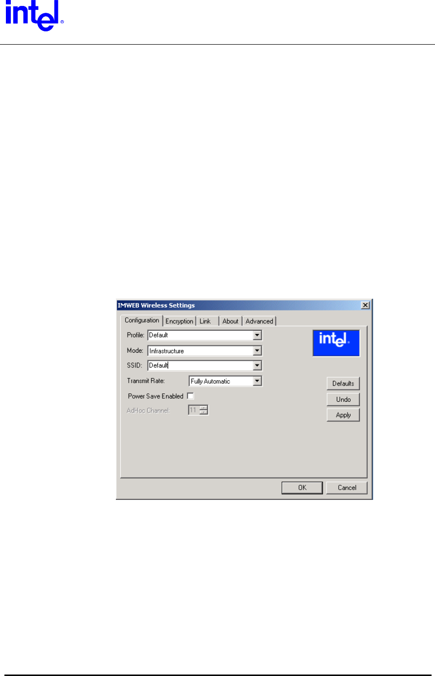
Support Software
IMWEBSTA.EXE
IMWEBsta.exe is the system tray utility that launches the configuration
software utility for this product. The software allows a user to do the following
actions:
• Configure the SSID (Service Set Identifier)
• Specify operating mode (Infrastructure, 802.11 Ad-Hoc)
• Specify Transmit Rate (Auto, 1-2 Mb, 5.5 Mb, 11 Mb, Fully Automatic)
• Disable or modify encryption settings (Disabled, 64bit, 128 bit)
• View link status (Link Quality, Signal Strength, Throughput, Tx Rate)
• View current Channel
• View current associations
• Rescan option. Forces the radio to rescan all available channels
• View current Network driver version
• View current firmware version
• Enable/Disable Radio
(Screen Shot)
This utility is supported under Microsoft Windows 98, Windows 98SE, Windows
ME, Windows NT4, Windows 2000, and Windows XP operating systems. Under
Windows XP, the appearance of the system tray utility can change. Certain menu
options will not be available in Windows XP if the zero config service (aka .1x) is
active.
Intel Confidential – Controlled Access
Page 17 of 29

Trilogy 3 MPCI
M3AWEB/56GA
Product Specification
Ethernet Software Matrix
File Name Type
IMWEBsta.exe Tray Application
(Common)
IMWEBIOC.dll Driver API Agent
(Common)
IMWEBIOC.vxd Virtual Device Driver
( Win98/98SE)
IMWEBCFG.cpl Control Panel Ext
(NT5)
IMWEBCFG.cpl Control Panel Ext
(NT4)
IMWEBCFG.dll NDI App Extension
(Win16)
IMWEBRes.dll Resource Dll
(Win32)
IMWEBR16.dll Resource DLL (Win16)
IMWEBN5.sys NDIS5.0 Driver
IMWEBN4.sys NDIS4.0 Driver
NetIMWEB.inf Win Info File
(Win2K,98,98SE,Me,XP)
Oemsetup.inf Win Info File
(NT4)
Setup.exe InstallShield Installer
Intel Confidential – Controlled Access
Page 18 of 29

Trilogy 3 MPCI
M3AWEB/56GA
Product Specification
Modem Software Driver and Feature Set
Operating System Software Support
• Microsoft Windows XP
• Microsoft NT4.0 (SYS drivers)
• Windows 2000 (WDM drivers)
• Windows 98 (WDM and VxD drivers)
• Windows Millennium (WDM drivers)
• PC ‘99 compliant
• ACPI compliant
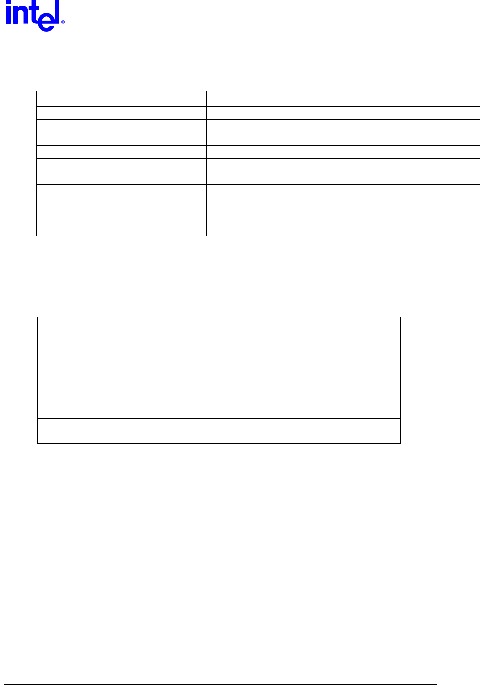
AC’97 Modem Driver Package File Description
The following table shows the file description of the most typical Scorpio modem
driver package. (Driver package for Windows XP will be the same as Win2K
package.)
R: Required files
O: Optional files
S: SETUP related files
D: Debug purpose only files
Intel Confidential – Controlled Access
Page 19 of 29

Trilogy 3 MPCI
M3AWEB/56GA
Product Specification
Table 1. Scorpio Driver Package Description
File Name Description 98/SE NT4 ME W2K
Ltsetup1.dll Agere setup dll file S S S S
Ltsetup2.dll Agere setup dll file S S S S
Ltsetup3.exe Agere setup executable for Win95 only S S S S
Setup.exe Agere setup main executable – called by user S S S S
Ltremove.exe Agere device remove executable S S S S
Ltsetup.ini Agere setup information file S S S S
Ltsm.sys WDM type modem driver R R
Ltsm.sys NT4 SYS type modem driver R
Ltsm.vxd VxD type modem driver R
Ltsm9md.inf Windows INF file R
Ltsm9md.cat Catalog (digital signature) file for Ltsm9md.inf R
Ltsm9pc.inf Windows INF file R
Ltsm9pc.cat Catalog (digital signature) file for Ltsm9pc.inf R
Ltsmdmi.dll Implements DOS compatibility tab in modem
properties
O O
Ltsmmsg.exe User messaging utility R/O* R/O* R/O* R/O*
Ltsmnt4.inf Windows INF file R
Ltsmnum.vxd Helper VxD for DOS box support R
Ltsmvcd.vxd Helper VxD for DOS box support R R
Ltsmvxd.inf Windows INF file R
Ltsmvxd.cat Catalog (digital signature) file for Ltsmw2k.inf R
Ltsmw2k.inf Windows INF file R
Ltsmw2k.cat Catalog (digital signature) file for Ltsmw2k.inf R
Ltsmmsg.exe Required if system audio is used for call progress. Otherwise LtsmMsg.exe is used to
display user warning messages such as over current condition or invalid country/region
selection.
Intel Confidential – Controlled Access
Page 20 of 29

Trilogy 3 MPCI
M3AWEB/56GA
Product Specification
SETUP Usage
Agere supplies a simplified user friendly driver setup program along with the
modem driver package, called SETUP. The setup program works on all Windows
operating systems (Win98/98SE/ME/NT4/2K/XP) and performs the following
functions:
• Install modem driver
• Copy modem related files upon installing modem
• Launch modem related executables upon installing modem
• Uninstall modem driver
• Clean up modem related registry information upon uninstallation of modem
• Delete modem related files from the system upon uninstallation of modem
SETUP Customization
Customization to SETUP can be made by editing ltsetup.ini file. This gives OEMs
more flexibility in the way the setup program operates under their systems. Here
is the detail description of ltsetup.ini.
Intel Confidential – Controlled Access
Page 21 of 29

Trilogy 3 MPCI
M3AWEB/56GA
Product Specification
Table 2. [ltsetup.ini]
[INSTALL_OPTIONS] Section defines all the installation options.
;File version 1.37 Setup program version
Debug=N Debug=Y will enable debug mode operation.
WDMDriver=N WDMDriver=Y will install WDM driver for Win98SE
instead of VxDs.
ReBoot=N For W9x/ME/2K/XP, ReBoot=Y will prompt user to
reboot the system after installing the driver. (NT4
will always ask to reboot the system.)
CleanUpRegistry=Y Enable clean up the registry keys specified in
[CLEANUPPATH] section.
CopyFilesW2K=N In W2K, copy files only, does not refresh the
system. (Should not be documented later.)
;SilentInstall=Y Enable silent install mode.
;CabsFlag=Y Enable ltremove to set SourcePath to
\Windows\options\cabs for WinME. It is set to
\windows\options\install by default.
;CatFlag=Y Enable to use SetupCopyOemInf to copy W2K INF
files.
CabExtract=N Enable cab file extraction feature upon installing
modem driver.
[COPY_FILES_9X]
;FILE0=filename1, $windows\system
FILE1=ltremove.exe
Section allows copying specific files (to specific
locations) other than default driver/INF/exe in
Win9x.
[COPY_FILES_NT]
FILE0=ltmsg.exe
FILE1=ltremove.exe
;FILE2=filename1, $windows\system32
Section allows copying specific files (to specific
locations) other than default driver/INF/exe in NT4.
[COPY_FILES_Win2K]
;FILE0=ltmsg.exe
FILE1=ltremove.exe
;FILE2=filename, $windows\system32
Section allows copying specific files (to specific
locations) other than default driver/INF/exe in
W2K/XP.
[DELETE_FILES_9X]
FILE0=ageresoftmodem.htm, $windows
Section allows deleting specific files upon
uninstallation of the modem driver in Win9x.
[DELETE_FILES_NT]
FILE0=ageresoftmodem.htm, $windows
Section allows deleting specific files upon
uninstallation of the modem driver in NT4.
[DELETE_FILES_Win2K]
FILE0=ageresoftmodem.htm, $windows
Section allows deleting specific files upon
uninstallation of the modem driver in W2K/XP.
[LAUNCH_FILES_9X]
FILE0=lthomol.exe
Section allows launching specified executable (at
specific directory location) upon installation of the
Intel Confidential – Controlled Access
Page 22 of 29

Trilogy 3 MPCI
M3AWEB/56GA
Product Specification
;FILE1=filename arg1 arg2,
$windows\system
specific directory location) upon installation of the
modem driver in Win9x.
[LAUNCH_FILES_NT]
FILE0=lthomol.exe
;FILE1=filename arg1 arg2,
$windows\system32
Section allows launching specified executable (at
specific directory location) upon installation of the
modem driver in NT4.
[LAUNCH_FILES_Win2K]
FILE0=lthomol.exe
;FILE1=filename arg1 arg2,
$windows\system32
Section allows launching specified executable (at
specific directory location) upon installation of the
modem driver in W2K/XP.
[IDS_TO_BE_INSTALLED]
id0=10B9&DEV_5450
id1=1039&DEV_7013
id2=8086&DEV_2446
id3=8086&DEV_2486
id4=8086&DEV_7196
id5=1106&DEV_3068
Specify the motherboard chipset IDs (PCI vendor ID
and device ID) which the modem is installed to (up
to 20 IDs).
[CLEANUPPATH]
Path0="Software\\Lucent\\SoftModem"
Specify the registry path to be clean up upon
uninstallation of modem driver.
[REGDELKEYS]
Path0="Software\\Lucent"
Specify the registry keys for modem uninstallation.
[CABNAME]
Cabname=agrsm.cab
Specify the cab file being extracted by setup.
[CABPATH]
;path="C:\ageresoftmodemhelp”
Path="C:\Program Files\agere\scorpio"
;path="C:\cabxtracts"
Specify the directory location where the cab file is
being extracted. Setup will create the sub directory
by itself assuming parent directory already exists in
the system. (i.e. \scorpio should be created under
existing directory C:\Program Files\agere )
Intel Confidential – Controlled Access
Page 23 of 29

Trilogy 3 MPCI
M3AWEB/56GA
Product Specification
Multilanguage Support
SETUP also offers multi language support. It automatically picks up the language
used in the system and displays the messages in each language. The supported
languages include:
English Dutch German Norwegian
Chinese (Simplified) Finnish Italian Portuguese (Brazilian)
Chinese (Traditional) French (Canadian) Japanese Spanish
Danish French (French) Korean Swedish
Intel Confidential – Controlled Access
Page 24 of 29

Trilogy 3 MPCI
M3AWEB/56GA
Product Specification
LTHOMOL.exe (Homologation support utility)
Agere Scorpio modem offers worldwide support over 60 country/region modes.
This homologation capability is enabled by the certain modem hardware (DAA -
analog front-end design) and the software (Device driver). The device driver
configures various parameters and sets the modem to function under certain
telecommunication regulation and laws to pass PTT approvals. This capability
allows PC OEMs and retail manufactures to market their products in more
countries/regions. It will also enables end-users to have more mobility of the
modem usage in laptop PC environments. While over 100 homologation
parameters have their default values configured in the modem driver,
LTHOMOL.exe adds the capability to modify/update the parameters that matches
with the certain modem hardware to be installed.
;This section allows to patch existing country settings or add new
country.
;format is Snnn=defaultValue,minValue,maxValue
;minValue and maxValue are ignored for debug registers (>=500)
;[B5] Country/Region code
;S0=4,4,8 Parameter S0
;S516=0x21 Parameter S516
;
;This section allows to disable support for specific countries.
:
;[Disable_Country]
;0A
;0F
;B6
For the detail of the country/region codes and homologation parameters settings,
please refer to Lucent Technologies Homologation Parameter Values for the
LU97 Soft Modem Chip Set manual (Jan/2001).
Intel Confidential – Controlled Access
Page 25 of 29

Trilogy 3 MPCI
M3AWEB/56GA
Product Specification
LTSMMSG.exe (User messaging & system audio support utility)
LTSMMSG.exe is a stand-alone program that offers you to show pop-up
windows to indicate users for certain critical events occurred, while users are
using the modem function. This program supports all Windows operating
systems.
Selection of Un-homologated Country Messaging
If the user selects some country which the modem is not homologated, either
from Regional Settings and/or Modem, Dialing Properties, My Location in Control
Panel, this warning message will show up.
Modem is not approved in the selected country.
Selecting a country other than the one in which you are currently
located may cause your modem to be configured in a way that
violates the telecommunication regulations/laws of that country.
In addition, your modem may not function properly if the correct
country selection is not made. Only select the country in which you
are located.
Country/region setting of the modem will remain the same as it was before if an
un-homologated country/region is selected. In addition the modem function itself
will not be blocked by this program.
To enable this feature the following line is needed in the INF file(s) for each
operating system.
[PortMod.AddReg]
HKLM,SOFTWARE\Microsoft\Windows\CurrentVersion\Run,LTSMMSG,,LTS
MMSG.exe
(Launch LTSMMSG.exe upon Windows boot-up.)
Intel Confidential – Controlled Access
Page 26 of 29

Trilogy 3 MPCI
M3AWEB/56GA
Product Specification
Over Current Protection (OCP) Messaging
When the user is on the road or even at home and accidentally plugs modem into
RJ-11 jack that is a digital PBX line, the modem will not go off hook to protect the
modem hardware to be damaged by high voltage/current line condition. Upon off
hook event, the following warning message will show up.
“The modem is plugged into a digital PBX line and will not work.”
The modem hardware has to equip the over current protection circuit to support
this feature.
To enable this feature the following line is needed in the INF file(s) for each
operating system.
[PortMod.AddReg]
HKLM,SOFTWARE\Microsoft\Windows\CurrentVersion\Run,LTSMMSG,,LTS
MMSG.exe
(Launch LTSMMSG.exe upon Windows boot-up.)
Intel Confidential – Controlled Access
Page 27 of 29

Trilogy 3 MPCI
M3AWEB/56GA
Product Specification
System Audio Support
LTSMMSG.exe also serves as a Windows user mode ring-3 application which
samples audio data stream generated by the driver and transfers the data onto
the system audio device. This will allow the system to support call progress tone
monitor function without using PWM (Pulse Width Modulation) speaker function
that is previously supported. This new feature eliminates the external
components (circuit) required for PWM speaker support and will help reducing
the BOM (Bill of Material) and the size of the modem hardware.
To enable this feature the following line is needed in the INF file(s) for each
operating system. (Example of system audio support in Intel Solano2 system)
[Lucent_Modems]
%INTEL_AMR.Modem% = INTEL_AMR_SA.Modem,
PCI\VEN_8086&DEV_2446&SUBSYS_12345678
(INTEL_AMR_SA.Modem entry enables system audio support in Intel system.)
[ControlFlags]
ExcludeFromSelect = PCI\VEN_8086&DEV_2446&SUBSYS_12345678
(Match the ID string with above [Lucent_Modems] ID entry.)
[PortMod.AddReg]
HKLM,SOFTWARE\Microsoft\Windows\CurrentVersion\Run,LTSMMSG,,LTSMMSG.
exe
HKLM,SOFTWARE\Lucent\SoftModem,CallProgressPlayThreshold,1,a0,1f,00,00
(Launch LTSMMSG.exe upon Windows boot-up and specify the audio sample
playback latency.)
If the PC OEM requires just the system audio support, the following line will
disable user messaging functions in the INF file(s) for each operating system.
[PortMod.AddReg]
HKLM,SOFTWARE\Lucent\SoftModem,SoftModemMsgDisable,1,FF,FF,FF,FF
This system audio support is officially implemented from version 3.1.90 release
and onward.
Intel Confidential – Controlled Access
Page 28 of 29

Trilogy 3 MPCI
M3AWEB/56GA
Product Specification
Intel Confidential – Controlled Access
Page 29 of 29
Quality
Product design requirements
• This product will meet the validation requirements as documented in the Intel
qualification methodology specification, 25-GS-3000.
Environmental requirements
• This product will meet the environmental and reliability test profiles for boards and
systems per the Intel environmental standards handbook (specification 662394-04)
Statistical tool
• Specification 25-GS-3010 will be used to determine various build quantities to ensure
qualification and product health post-launch.
Product manufacturing requirements
• This product will meet the validation requirements as documented in the Intel
qualification methodology specification, 25-GS-3000.
• Product cosmetics must meet Intel’s workmanship standards. Document number
61957.
Product qualification
• This product will meet and / or exceed the requirements as outlined in the Intel
product qualification methodology specification, 25-GS-3000
Post-launch product health through end of life
• The number of defects found will not exceed 1500 DPM as measured by out-going
quality monitor (OQM)
Federal Communication Commission Interference Statement
This equipment has been tested and found to comply with the limits for a Class B digital device,
pursuant to Part 15 of the FCC Rules. These limits are designed to provide reasonable
protection against harmful interference in a residential installation. This equipment generates,
uses and can radiate radio frequency energy and, if not installed and used in accordance with
the instructions, may cause harmful interference to radio communications. However, there is no
guarantee that interference will not occur in a particular installation. If this equipment does cause
harmful interference to radio or television reception, which can be determined by turning the
equipment off and on, the user is encouraged to try to correct the interference by one of the
following measures:
- Reorient or relocate the receiving antenna.
- Increase the separation between the equipment and receiver.
- Connect the equipment into an outlet on a circuit different from that to which the receiver is
connected.
- Consult the dealer or an experienced radio/TV technician for help.
FCC Caution: To assure continued compliance, (example - use only shielded interface cables
when connecting to computer or peripheral devices) any changes or modifications not expressly
approved by the party responsible for compliance could void the user's authority to operate this
equipment.
This device complies with Part 15 of the FCC Rules. Operation is subject to the following two
conditions: (1) This device may not cause harmful interference, and (2) this device must accept
any interference received, including interference that may cause undesired operation.
Statement Needed to be Shown on End Product
Since this module is installed inside the end product, the end product should be affixed a label on
visible area showing that this product contain a RF module, and also its FCC ID.
IMPORTANT NOTE:
FCC Radiation Exposure Statement:
This equipment complies with FCC radiation exposure limits set forth for an uncontrolled
environment. This equipment should be installed and operated with minimum distance 20cm
between the radiator & your body.
This transmitter must not be co-located or operating in conjunction with any other antenna or
transmitter.

This device is intended only for OEM integrators under the following conditions:
1) The antenna must be installed such that 20 cm is maintained between the antenna and users, and
2) The transmitter module may not be co-located with any other transmitter or antenna.
As long as the 2 conditions above are met, further transmitter testing will not be required. However,
the OEM integrator is still responsible for testing their end-product for any additional compliance
requirements required with this module installed (for example, digital device emissions, PC peripheral
requirements, etc.).
IMPORTANT NOTE: In the event that these conditions can not be met (for example certain laptop
configurations or co-location with another transmitter), then the FCC authorization is no longer
considered valid and the FCC ID can not be used on the final product. In these circumstances, the
OEM integrator will be responsible for re-evaluating the end product (including the transmitter) and
Obtaining a separate FCC authorization.
End Product Labelling
This transmitter module is authorized only for use in devices where the antenna may be installed such
that 20 cm may be maintained between the antenna and users (for example access points, routers,
wireless ASDL modems, and similar equipment). The final end product must be labeled in a visible
area with the following: “ Contains TX FCC ID: HFSM3AWEB ”.
Manual Information That Must be Included
The users manual for end users must include the following information in a prominent location “
IMPORTANT NOTE: To comply with FCC RF exposure compliance requirements, the antenna used for
this transmitter must be installed to provide a separation distance of at least 20 cm from all persons and
must not be co-located or operating in conjunction with any other antenna or transmitter.”
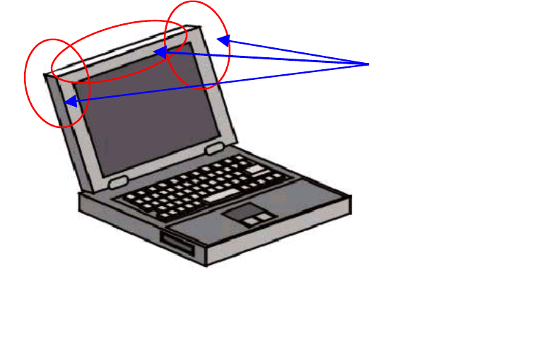
Statement for Warning & Configuration
1. This device is only for OEM integrator.
2. The use of this device is limited to notebook.
3. Antenna should be the antenna used in FCC’s authorization for ID: HFSM3AWEB
and it should be the integral part of the notebook with the installation configuration
shown in the following diagram.
Allowed Antenna
Locations