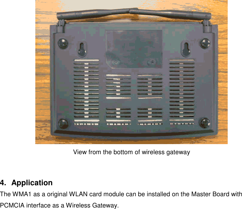
Quanta Computer MSBUQCI Wireless PCMCIA Card Module User Manual Revised Mamual

Quanta Computer Inc Wireless PCMCIA Card Module Revised Mamual

Revised Mamual

WMA1PCMCIA Type II Wireless LAN CardUser Manual
Federal Communication Commission Interference StatementThis equipment has been tested and found to comply with the limits for a Class B digital device,pursuant to Part 15 of the FCC Rules. These limits are designed to provide reasonableprotection against harmful interference in a residential installation. This equipment generates,uses and can radiate radio frequency energy and, if not installed and used in accordance withthe instructions, may cause harmful interference to radio communications. However, there isno guarantee that interference will not occur in a particular installation. If this equipment doescause harmful interference to radio or television reception, which can be determined by turningthe equipment off and on, the user is encouraged to try to correct the interference by one of thefollowing measures:- Reorient or relocate the receiving antenna.- Increase the separation between the equipment and receiver.- Connect the equipment into an outlet on a circuit different from that to which the receiver isconnected.- Consult the dealer or an experienced radio/TV technician for help.FCC Caution: To assure continued compliance, (example - use only shielded interface cableswhen connecting to computer or peripheral devices) any changes or modifications notexpressly approved by the party responsible for compliance could void the user's authority tooperate this equipment.This device complies with Part 15 of the FCC Rules. Operation is subject to the following twoconditions: (1) This device may not cause harmful interference, and (2) this device mustaccept any interference received, including interference that may cause undesired operation.Statement Needed to be Shown on End ProductSince this module is installed inside the end product, the end product should be affixed a labelon visible area showing that this product contain a RF module, and also its FCC ID.IMPORTANT NOTE:FCC Radiation Exposure Statement:This equipment complies with FCC radiation exposure limits set forth for an uncontrolledenvironment. This equipment should be installed and operated with minimum distance 20cmbetween the radiator & your body.This transmitter must not be co-located or operating in conjunction with any other antenna ortransmitter.
Manufacturer's Disclaimer StatementThe information in this document is subject to change without notice and does not represent acommitment on the part of the vendor. No warranty or representation, either expressed orimplied, is made with respect to the quality, accuracy or fitness for any particular purpose ofthis document.The manufacturer reserves the right to make changes to the content of this document and/orthe products associated with it at any time without obligation to notify any person ororganization of such changes. In no event will the manufacturer be liable for direct, indirect,special, incidental or consequential damages arising out of the use or inability to use thisproduct or documentation, even if advised of the possibility of such damages. This documentcontains materials protected by copyright. All rights are reserved. No part of this manual maybe reproduced or transmitted in any form, by any means or for any purpose without expressedwritten consent of its authors. Product names appearing in this document are mentioned foridentification purchases only. All trademarks, product names or brand names appearing in thisdocument are registered property of their respective owners.Printed in Taiwan
1. INTRODUCTION........................................................................................................................ 51.1 Overview.........................................................................................51.2 Features..........................................................................................52. DEVICE DESCRIPTION............................................................................................................ 52.1 Appearance before installed on the Master Board...................................52.2 Appearance after installed on the Master Board......................................63. INSTALLATION THE CARD ................................................................................................... 64. APPLICATION............................................................................................................................ 95. HARDWARE TECHNICAL SPECIFICATION OF WIRELESS LAN............................... 10STANDARD COMPLIANCE........................................................................................................ 10
1. Introduction1.1 OverviewThis user manual describes the feature of the PCMCIA wireless LAN card (modelname: WMA1), as well as the physical card installation.WMA1 complies with full IEEE 802.11b standards with bit rate up to 11Mbps and theinterface complies with PCMCIA specifications.The WMA1 module can be installed on a variety of gateway (or router) master boardsas various wireless gateways (or routers).1.2 Features* Fully IEEE 802.11b and Wi-Fi compatible* Working range up to 300 meters in an open environment* Seamless roaming under 802.11b WLAN infrastructure* Automatically Support basic rate at 11M/5.5M/2M/1M fall backfunctionality* WEP 64/128 bits encryption provided* Supply User-friendly installation: hardware auto-detection and softwareeasy-setup without manual configuration.* The powerful utility operates and communicates other WLAN devices* Direct Sequence Spread Spectrum (DSSS) technology provides robust,interference-resistant and wireless communication security.* Compatible with any computer under the OS of Microsoft Windowsseries: Windows 98/ME/2000/XP2. Device Description2.1 Appearance before installed on the Master BoardThe WMA1 wireless LAN card Module allows for placement on the Master board (Quanta BGSeries) using the attached bracket and screws. The installation steps are mentioned in section3.
Appearance of the WMA1 card and attached components (bracket and screws)2.2 Appearance after installed on the Master BoardAppearance of the complete WMA1 installation3.  Installation the CardTo physically install the WMA1 onto the PCMCIA interface Master Board, please follow thesteps below:
Step 1: Slide the WMA1 PCMCIA Wireless LAN Card Module over the Quanta Gatewaymaster board.Appearance of the WMA1 card and attached components (bracket and screws)Appearance of the Quanta Gateway Master BoardStep 2: Directly align the WMA1 card pins to the mapping PCMCIA interface port and thenplug-in it.Step 3: Use the screwdriver to mount the screws and the attached bracket onto the Master
board.Step 4: Mount the external antenna to WMA1.Appearance of the complete WMA1 installationStep 5: Put the gateway cover on and the installation is all set.Appearance of the front panel of wireless gateway
View from the bottom of wireless gateway4. ApplicationThe WMA1 as a original WLAN card module can be installed on the Master Board withPCMCIA interface as a Wireless Gateway.
5.  Hardware Technical Specification of Wireless LANStandard ComplianceIEEE 802.11b standard and WECA interoperability certified FCC part 15,sec.15. 247/USACE/ETSI 300.328,300.826/EurpoeTELEC/JapanElectrical SpecificationParameter name Value RemarkSupply voltage range 3.0V~3.6V DC Bus poweredAverage current: 290 mA typical 2% transmit, 98% receivewithout power saving modeAVERAGE CURRENT: 75 mA typical 2% transmit, 8% receive90% standby with power savingmodeContinuous transmit mode 315 mA maxContinuous receive mode: 270 mA maxStandby mode: 51 mA max with power saving modeForm FactorComply with PCMCIA Type II    Form Factor.Connectivity SpecificationComply with the PCMCIA Standard(release 2.0)Environmental SpecificationParameter name Value RemarkTemperature Range 0~55ºC OperationTemperature Range -20~65ºC StorageRelative Humidity 95% maxVibration 15G 10 to 2000Hz, non-operating
Parameter name Value RemarkEMI FCC class BESD 1500V Non-operatingFrequency AllocationRegulatory Domain Operating frequencyrange No. of operatingchannelsNorth America 2412~2462MHZ 11channel(3 non-overlapping)Europe 2412~2472MHZ 13channel(3 non-overlapping)Japan 2412~2484MHZ 14channelsModulation/Data rateData Rate Modulation1M bps DBPSK2M bps DQPSK5.5M bps CCK11M bps CCKAntenna SpecificationAntenna Type: 2 PCB Antenna for Space DiversityReceive SensitivityModulation/Rate Sensitivity Spec(dBm, Typ.) Allowed PERDBPSK (1M bps) -87dBm 8% PER or lessDQPSK (2M bps) -85dBm 8% PER or lessCCK (5.5M bps) -84dBm 8% PER or lessCCK (11M bps) -82dBm 8% PER or less
Dynamic RangeParameter name Value RemarkDynamic Range 82 dB Maximum Input level is –5dBmSystem Linearity((((Input))))Input third orderintercept point Value RemarkIIP3 -17 dBm Min. @-28dBm inputIIP3 13 dBm Min. @-1dBm inputAdjacent Channel RejectionReceive Adjacent Channel Rejection shall be tested with a 25MHz Separation and the desiredchannel input power is –80dBm.GeneralSpecification Value RemarkAdjacent channelrejection 35dB. PER<8%  @25MHz jammer offsetTransmitter Power OutputParameter name Value RemarkTXP 13±1dBm Preliminary measuredMeasured at antenna port!  1st side lobe < -30dBc!  2nd side lobe < -50dBcTXP Range(ALCon)0dB typical
TX Carrier Suppression25dB Min.Preamble LengthShort/LongMultipath Fading Equalization"  80 ns rms at 11Mbps"  160 ns rms at 5.5Mbps"  280 ns rms at 1M or 2M bps

Navigation menu