Quanta Computer MSBUQCI Wireless PCMCIA Card Module User Manual Revised Mamual
Quanta Computer Inc Wireless PCMCIA Card Module Revised Mamual
Revised Mamual
WMA1
PCMCIA Type II Wireless LAN Card
User Manual
Federal Communication Commission Interference Statement
This equipment has been tested and found to comply with the limits for a Class B digital device,
pursuant to Part 15 of the FCC Rules. These limits are designed to provide reasonable
protection against harmful interference in a residential installation. This equipment generates,
uses and can radiate radio frequency energy and, if not installed and used in accordance with
the instructions, may cause harmful interference to radio communications. However, there is
no guarantee that interference will not occur in a particular installation. If this equipment does
cause harmful interference to radio or television reception, which can be determined by turning
the equipment off and on, the user is encouraged to try to correct the interference by one of the
following measures:
- Reorient or relocate the receiving antenna.
- Increase the separation between the equipment and receiver.
- Connect the equipment into an outlet on a circuit different from that to which the receiver is
connected.
- Consult the dealer or an experienced radio/TV technician for help.
FCC Caution: To assure continued compliance, (example - use only shielded interface cables
when connecting to computer or peripheral devices) any changes or modifications not
expressly approved by the party responsible for compliance could void the user's authority to
operate this equipment.
This device complies with Part 15 of the FCC Rules. Operation is subject to the following two
conditions: (1) This device may not cause harmful interference, and (2) this device must
accept any interference received, including interference that may cause undesired operation.
Statement Needed to be Shown on End Product
Since this module is installed inside the end product, the end product should be affixed a label
on visible area showing that this product contain a RF module, and also its FCC ID.
IMPORTANT NOTE:
FCC Radiation Exposure Statement:
This equipment complies with FCC radiation exposure limits set forth for an uncontrolled
environment. This equipment should be installed and operated with minimum distance 20cm
between the radiator & your body.
This transmitter must not be co-located or operating in conjunction with any other antenna or
transmitter.
Manufacturer's Disclaimer Statement
The information in this document is subject to change without notice and does not represent a
commitment on the part of the vendor. No warranty or representation, either expressed or
implied, is made with respect to the quality, accuracy or fitness for any particular purpose of
this document.
The manufacturer reserves the right to make changes to the content of this document and/or
the products associated with it at any time without obligation to notify any person or
organization of such changes. In no event will the manufacturer be liable for direct, indirect,
special, incidental or consequential damages arising out of the use or inability to use this
product or documentation, even if advised of the possibility of such damages. This document
contains materials protected by copyright. All rights are reserved. No part of this manual may
be reproduced or transmitted in any form, by any means or for any purpose without expressed
written consent of its authors. Product names appearing in this document are mentioned for
identification purchases only. All trademarks, product names or brand names appearing in this
document are registered property of their respective owners.
Printed in Taiwan

1. INTRODUCTION........................................................................................................................ 5
1.1 Overview
.........................................................................................5
1.2 Features
..........................................................................................5
2. DEVICE DESCRIPTION............................................................................................................ 5
2.1 Appearance before installed on the Master Board
...................................5
2.2 Appearance after installed on the Master Board
......................................6
3. INSTALLATION THE CARD ................................................................................................... 6
4. APPLICATION............................................................................................................................ 9
5. HARDWARE TECHNICAL SPECIFICATION OF WIRELESS LAN............................... 10
STANDARD COMPLIANCE
........................................................................................................ 10
1. Introduction
1.1 Overview
This user manual describes the feature of the PCMCIA wireless LAN card (model
name: WMA1), as well as the physical card installation.
WMA1 complies with full IEEE 802.11b standards with bit rate up to 11Mbps and the
interface complies with PCMCIA specifications.
The WMA1 module can be installed on a variety of gateway (or router) master boards
as various wireless gateways (or routers).
1.2 Features
* Fully IEEE 802.11b and Wi-Fi compatible
* Working range up to 300 meters in an open environment
* Seamless roaming under 802.11b WLAN infrastructure
* Automatically Support basic rate at 11M/5.5M/2M/1M fall back
functionality
* WEP 64/128 bits encryption provided
* Supply User-friendly installation: hardware auto-detection and software
easy-setup without manual configuration.
* The powerful utility operates and communicates other WLAN devices
* Direct Sequence Spread Spectrum (DSSS) technology provides robust,
interference-resistant and wireless communication security.
* Compatible with any computer under the OS of Microsoft Windows
series: Windows 98/ME/2000/XP
2. Device Description
2.1 Appearance before installed on the Master Board
The WMA1 wireless LAN card Module allows for placement on the Master board (Quanta BG
Series) using the attached bracket and screws. The installation steps are mentioned in section
3.
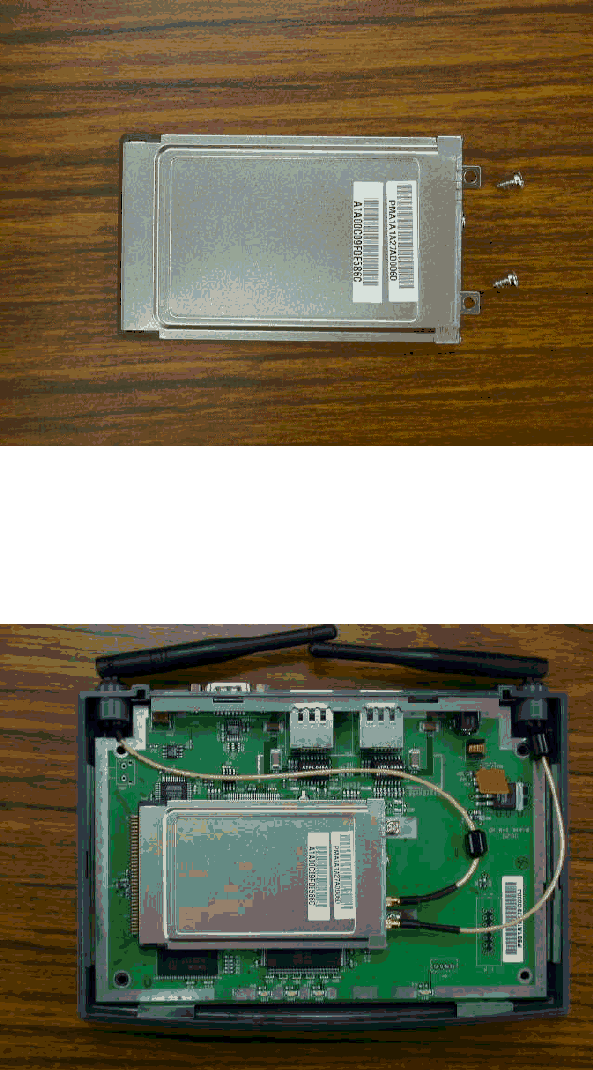
Appearance of the WMA1 card and attached components (bracket and screws)
2.2 Appearance after installed on the Master Board
Appearance of the complete WMA1 installation
3. Installation the Card
To physically install the WMA1 onto the PCMCIA interface Master Board, please follow the
steps below:
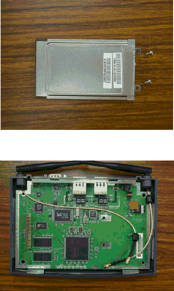
Step 1: Slide the WMA1 PCMCIA Wireless LAN Card Module over the Quanta Gateway
master board.
Appearance of the WMA1 card and attached components (bracket and screws)
Appearance of the Quanta Gateway Master Board
Step 2: Directly align the WMA1 card pins to the mapping PCMCIA interface port and then
plug-in it.
Step 3: Use the screwdriver to mount the screws and the attached bracket onto the Master
board.
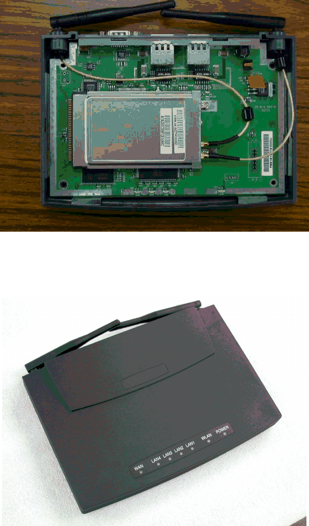
Step 4: Mount the external antenna to WMA1.
Appearance of the complete WMA1 installation
Step 5: Put the gateway cover on and the installation is all set.
Appearance of the front panel of wireless gateway
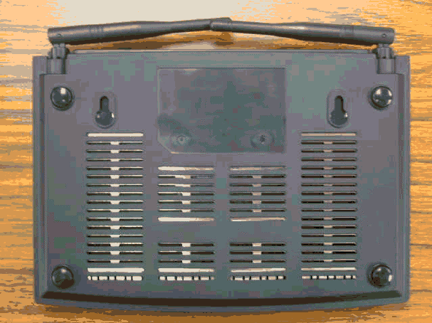
View from the bottom of wireless gateway
4. Application
The WMA1 as a original WLAN card module can be installed on the Master Board with
PCMCIA interface as a Wireless Gateway.
5. Hardware Technical Specification of Wireless LAN
Standard Compliance
IEEE 802.11b standard and WECA interoperability certified FCC part 15,sec.15. 247/USA
CE/ETSI 300.328,300.826/Eurpoe
TELEC/Japan
Electrical Specification
Parameter name Value Remark
Supply voltage range 3.0V~3.6V DC Bus powered
Average current: 290 mA typical 2% transmit, 98% receive
without power saving mode
AVERAGE CURRENT: 75 mA typical 2% transmit, 8% receive
90% standby with power saving
mode
Continuous transmit mode 315 mA max
Continuous receive mode: 270 mA max
Standby mode: 51 mA max with power saving mode
Form Factor
Comply with PCMCIA Type II Form Factor.
Connectivity Specification
Comply with the PCMCIA Standard(release 2.0)
Environmental Specification
Parameter name Value Remark
Temperature Range 0~55ºC Operation
Temperature Range -20~65ºC Storage
Relative Humidity 95% max
Vibration 15G 10 to 2000Hz, non-operating
Parameter name Value Remark
EMI FCC class B
ESD 1500V Non-operating
Frequency Allocation
Regulatory Domain Operating frequency
range No. of operating
channels
North America 2412~2462MHZ 11channel
(3 non-overlapping)
Europe 2412~2472MHZ 13channel
(3 non-overlapping)
Japan 2412~2484MHZ 14channels
Modulation/Data rate
Data Rate Modulation
1M bps DBPSK
2M bps DQPSK
5.5M bps CCK
11M bps CCK
Antenna Specification
Antenna Type: 2 PCB Antenna for Space Diversity
Receive Sensitivity
Modulation/Rate Sensitivity Spec(dBm, Typ.) Allowed PER
DBPSK (1M bps) -87dBm 8% PER or less
DQPSK (2M bps) -85dBm 8% PER or less
CCK (5.5M bps) -84dBm 8% PER or less
CCK (11M bps) -82dBm 8% PER or less

Dynamic Range
Parameter name Value Remark
Dynamic Range 82 dB Maximum Input level is –5dBm
System Linearity(
((
(Input)
))
)
Input third order
intercept point Value Remark
IIP3 -17 dBm Min. @-28dBm input
IIP3 13 dBm Min. @-1dBm input
Adjacent Channel Rejection
Receive Adjacent Channel Rejection shall be tested with a 25MHz Separation and the desired
channel input power is –80dBm.
General
Specification Value Remark
Adjacent channel
rejection 35dB. PER<8% @25MHz jammer offset
Transmitter Power Output
Parameter name Value Remark
TXP 13±1dBm Preliminary measured
Measured at antenna port
! 1st side lobe < -30dBc
! 2nd side lobe < -50dBc
TXP Range(ALC
on)
0dB typical
TX Carrier Suppression
25dB Min.
Preamble Length
Short/Long
Multipath Fading Equalization
" 80 ns rms at 11Mbps
" 160 ns rms at 5.5Mbps
" 280 ns rms at 1M or 2M bps